Zamil DY-KY series.pdf
23
Concealed Fan Coil Units DY18/KY018 thru DY60/KY060 1.5 TR thru 5 TR 5 kW thru 17.5 kW Cool & Heat pump models
-
Upload
jojo-abordo-fernandez -
Category
Documents
-
view
945 -
download
118
Transcript of Zamil DY-KY series.pdf

Concealed Fan Coil UnitsDY18/KY018 thru DY60/KY060
1.5 TR thru 5 TR5 kW thru 17.5 kW
Cool & Heat pump models

Company BusinessZamil Air Conditioners was founded in 1974 as one of the first air conditioning business to be established in Saudi Arabiaand today is a leading international manufacturer of air conditioning systems and is No. 1 in the Middle East.
Zamil Air conditioners manufactures both consumer and central air conditioners and has sales operations in over 55countries in the Middle East, Europe, Africa and Asia.
The company’s operations are structured into four Strategic Business Units (SBUs) supporting five in-house product andservice brands as well as a number of international brands under the OEM sales.
The five in-house brands are Classic, Cooline, CoolCare, Clima Tech and Geoclima.
The four SBUs are:1. Consumer Business Unit supporting Classic, Cooline, GE and OEM brands for consumers.2. Unitary & Applied Business Unit supporting Classic, Cooline, GE and OEM brands for commercial and industrial
customers.3. Zamil CoolCare providing engineering & project management services, HVAC maintenance, retrofit services and parts.4. Geoclima srl is an independent business supporting other SBUs for their requirement of Chillers & Double skin AHU’s.
The first three SBUs - Consumer Products, Unitary & Applied Products and CoolCare Service direct their businessoperations from the corporate headquarters at Dammam, Saudi Arabia.
Geoclima has its engineering & production departments located at Monfalcone, Italy and has a design center in Austria.
All the four SBUs, while operating independently, supplement each other’s activities in a way that makes synergy work atits best and achieve the corporate goals of maximizing customer satisfaction.
Factories and ProductionsZamil Air Conditioners has two manufacturing plants in Dammam, Saudi Arabia and has one speciality production facilityin Italy operated by Geoclima.
The company can produce up to 550,000 Room Air Conditioners, 300,000 Mini-Split systems and 50,000 Central AirConditioning systems per year.
Quality & Product CertificatesThe Quality systems and policies at Zamil Air Conditioners comply with the required ISO 9001:2000 certification.
Zamil Air Conditioners is the first company in Saudi Arabia to receive the SASO (Saudi Arabia’s Standard Organization)Certificate for Room Air Conditioners. ZAC's products are also certified with:1. CE (Council of European Community)2. UL (Underwriters Laboratory)3. Eurovent4. ASME5. ETL
Other awards include the prestigious Engineering Excellence Award of General Electric and the inaugural Prince Mohammedbin Fahd Al Saud Award for Factory Safety.
Our ProductsIn addition to the consumer products such as the Room Air Conditioners (RAC) and the Mini Splits, Zamil Air Conditionersmanufacturers a host of residential, commercial and industrial air conditioners. This broad range extends from the Con-cealed Units up to 5 tons, the Ducted Splits up to 30 tons, the Packaged Units up to 90 tons, the Single and Double SkinAir Handling Units up to 70,630 CFM and the Water Chillers up to 660 tons cooling capacity.
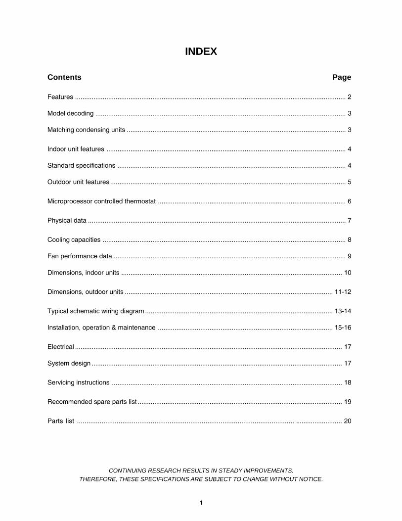
Contents Page
Features ................................................................................................................................................... 2
Model decoding ........................................................................................................................................ 3
Matching condensing units ....................................................................................................................... 3
Indoor unit features .................................................................................................................................. 4
Standard specifications ............................................................................................................................ 4
Outdoor unit features ................................................................................................................................ 5
Microprocessor controlled thermostat ...................................................................................................... 6
Physical data ............................................................................................................................................ 7
Cooling capacities .................................................................................................................................... 8
Fan performance data .............................................................................................................................. 9
Dimensions, indoor units ........................................................................................................................ 10
Dimensions, outdoor units ................................................................................................................. 11-12
Typical schematic wiring diagram ...................................................................................................... 13-14
Installation, operation & maintenance ............................................................................................... 15-16
Electrical ................................................................................................................................................. 17
System design ........................................................................................................................................ 17
Servicing instructions ............................................................................................................................. 18
Recommended spare parts list ............................................................................................................... 19
Parts list ................................................................................................................... ......................... 20
INDEX
CONTINUING RESEARCH RESULTS IN STEADY IMPROVEMENTS.THEREFORE, THESE SPECIFICATIONS ARE SUBJECT TO CHANGE WITHOUT NOTICE.
1

FEATURESHYBRID DESIGN BETWEEN MINI SPLITS AND CENTRAL UNITS
INDOOR UNIT :
* COMPACT DESIGN WITH LOW PROFILE
* HEIGHT RANGES FROM 9.6" TO 14.5"
* UNITS ARE FOR DUCTED APPLICATIONS
* LOW SOUND LEVELS
* DRAW THRU AIRFLOW CONFIGURATION
* 3 SPEED MOTORS
* REAR RETURN AIR FILTER
* EASY MAINTENANCE AND INSTALLATION
* G-90 GALVANIZED HEAVY GAUGE PANELS
* DIGITAL MICRO PROCESSOR CONTROL
* WIRED LCD DISPLAY THERMOSTAT
OUTDOOR UNIT :* G-90 GALVANIZED HEAVY GAUGE PANELS
* PAINT: ELECTROSTATIC POWDER COAT COOL GRAY COLOR
* HIGH EFFICIENCY TROPICAL DESIGN
* POWERFUL COMPRESSOR
* 24 VOLT CONTROL
* OPERATES UP TO 550C AMBIENT TEMPERATURE
* EXTERNAL SERVICE VALVES WITH GAUGE PORTS
* LOW PRESSURE SWITCH
* OPTIONAL COPPER OR COATED ALUMINUM FINS
* COIL GUARD PROTECTION
* SIDE AIR DISCHARGE
INDOOR UNIT - 'DY' SERIES
OUTDOOR UNIT - 'KY' SERIES(MODELS: KY042 - KY060)
2

MODEL DECODING
1 & 2BASIC
3, 4 & 5NOMINALCOOLINGCAPACITY
(MBH)
7REFRIGERA-
TION CIRCUIT
6ELECTRICAL
SUPPLY( V-Ph-Hz )
9MODE
11CONDENSER
COIL
KYCONDENSING
UNIT
018
024
030
036
042
048
060
S : SINGLEC : 208/230-1-60
H : 208/230-3-60*M : 380-3-60* (4 WIRE)
F : 460-3-60*
C : COOL ONLY
H : HEAT PUMP
A : ALUMINUM FIN
B :COATEDALUMINUMFIN
C : COPPER FIN
8COMPRESSOR
TYPE
R : HERMETICRECIPRO-CATING
13OPTIONS
10CONDENSER
MOTOR
N : STANDARD
L : LOWAMBIENT
12ACCESSORIES
N : STANDARDUNIT
F : STANDARDUNIT WITHFILTERDRIER &SIGHTGLASS
N : STANDARD UNIT
B : SECONDGENERATIONUNIT (FOR KY030ONLY)
* Applicable for KY030 - KY060 models only.
INDOOR UNIT
OUTDOOR UNIT
1 & 2BASIC (SERIES)
3 & 4COOLING CAPAC-ITY (x 1000 BTUH)
5ELECTRICAL
SUPPLY (V-Ph-Hz)
8FIN
7ACCESSORIES
11OPTION
DYDUCTED SPLITFAN COIL UNIT
18
24
30
36
42
48
60
C : 208/230-1-60 D : ALUMINUM FINSWITH ORIFICE
E : COATED FINSWITH ORIFICE
F : COPPER FINSWITH ORIFICE
*A : ALUMINUM FINSWITH CAPILLARY
*B : COATEDALUMINUM FINSWITH CAPILLARY
*C : COPPER FINSWITH CAPILLARY
N : STANDARD N : STANDARDUNIT
6REFRIGERATION
SYSTEM
C : COOL ONLY
H : HEAT PUMP
10FILTER
N : NONE
A : ALUMINUM
C : SYNTHETIC
9COIL
CONNECTION
R : RH SIDE(FACING AIRDISCHARGE)
* These options are for matching DY18/DY24/DY30 heat pump units with KY018/KY024/KY030 condensing units and also for matching DY36 to DY60 heat pump units withCX036 to CX060 condensing units.
INDOOR UNIT MODE
DY18COOL DY18CCNDRAN KY018CSRCNANN
HEAT PUMP DY18CHNARAN KY018CSRHNANN
DY24COOL DY24CCNDRAN KY024CSRCNANN
HEAT PUMP DY24CHNARAN KY024CSRHNANN
DY30COOL DY30CCNDRAN KY030CSRCNANB
HEAT PUMP DY30CHNARAN KY030CSRHNANB
DY36COOL DY36CCNDRAN KY036HSRCNANN
HEAT PUMP DY36CHNDRAN KY036HSRHNANN
DY42COOL DY42CCNDRAN KY042HSRCNANN
HEAT PUMP DY42CHNDRAN KY042HSRHNANN
DY48COOL DY48CCNDRAN KY048HSRCNANN
HEAT PUMP DY48CHNDRAN KY048HSRHNANN
DY60COOL DY60CCNDRAN KY060HSRCNANN
HEAT PUMP DY60CHNDRAN KY060HSRHNANN
MATCHING INDOOR/OUTDOOR UNITS
(FAN COIL UNIT)
NOTE: Refer to indoor/outdoor model decoding for other available voltages.
OUTDOOR UNITSINDOOR UNITS
3

INDOOR UNIT FEATURESCOMPACT DIMENSIONSLow height units are ideal to fit into tight spaces. Maximum height of unit ranges from 9.6" to 14.5" (24cm to 37cm).
EASY INSTALLATION WITH FLARE NUT CONNECTIONSNo need for complicated brazing for connecting the refrigerant piping.
EASY MAINTENANCE / ONE SIDE ACCESSFilters can be easily removed by lifting/sliding. Piping and controls are on one side for easy access.
DIGITAL & MICROPROCESSOR CONTROL WITH LCD DISPLAY THERMOSTATProgrammable wired thermostat loaded with all required functions and features for safe and smooth operation.
QUIET, PULSE FREE AIR SUPPLYCentrifugal fans that are statically and dynamically balanced, handle upto 0.5" w.g. (125pa) external static pressureallowing you to keep the unit away from your comfort zone.
MATCHED WITH RELIABLE CONDENSING UNITSFor optimum performance in cooling and heat pump applications.
STANDARD SPECIFICATIONSUNIT CONSTRUCTIONThese ducted indoor fan coil unit consists of a coil, motor/blower assembly, aluminum filter and a drain pan securelymounted on heavy gauge galvanized steel housing. Steel sheet panels are zinc coated and galvanized by the hot dipprocess of lock-forming quality conforming to ASTM A 653 commercial weight G-90.This unit is designed for those concealed overhead installations which require supply ductwork. A 1.5" duct collar isprovided into the front panel for supply air duct connection. Return air is from the rear side.Access to the blower assembly is provided through the removable bottom panel from where the complete fan/motor deckcan be removed for servicing. The panels are insulated with 5/16" thick polyethylene acoustic and thermal insulation.1/2" (13mm) thick washable type aluminum filter is provided.
BLOWER ASSEMBLYThe direct drive blower motor assembly is easily accessible for complete servicing after removal of fan deck from the unit.The blower wheels are large in diameter and are of the forward curved design. Constructed of steel, they are staticallyand dynamically balanced for quiet and smooth performance.
MOTORSMotors are permanent split capacitor type with three speed tapped windings. The bearings are of sleeve type.
COILSAll cooling coils are of corrugated fin & tube type, constructed of enhanced copper tubes and mechanically bonded toaluminum fins. As an option to aluminum fins, coated aluminum fins or corrugated copper fins may be provided. Tubesupport sheets are of galvanized steel, formed to provide structural strength. Coils are provided with the orifice type refrig-erant metering device on all models (except DY18/DY24/DY30 heat pump models). This provides for ease of serviceability.Unlike capillaries there is no need for de-brazing/brazing required for site replacements of the orifice pistons. Accuratelysized pistons can be easily fitted for non-standard applications (e.g. high rise buildings). Also this metering device elimi-nates the need for check valves in reverse cycle heat pump applications. All coils are factory tested at 350 psig.
DRAIN PANThe condensate drain pan is fabricated of 18 gauge galvanized steel. The drain pan is powder coat painted and the outersurface is thermally insulated. Since water never touches the metal pan, then possibility of corrosion is eliminated.
Quiet Operation Digital Thermostat Compact Dimensions High Cooling Capacity Easy Installation
4

OUTDOOR UNIT FEATURESA. GENERALThe Zamil side discharge condensing units incorporate the latest innovative technology to provide quiet, reliable perfor-mance. The wrap-around coil not only adds to the aesthetical appeal, it also gives optimum heat transfer efficiency.The access panels provide access to the compressor and to the electrical control box. Removal of top panel gives accessto fan motor and coil.These condensing units can be combined with a wide variety of evaporator coils and blower packages to provide quietand dependable comfort.These units are availed as standard cool only models, and also as heat pump versions as an option for added comfortduring cold season.
B. UNIT ENCLOSUREAll panels are of heavy gauge (G-90) galvanized steel sheet and completely weatherized for outdoor installation. Steelsheet panels are zinc coated and galvanized by the hot dip process of lock-forming quality conforming to ASTM A 653commercial weight G-90, followed by baked on electrostatic polyester dry powder coat.
C. COMPRESSORCompressors are fully hermetic type and are provided with all the standard controls necessary for proper and safeoperation. These compressors have improved internal pressure relief valve which provides high pressure protection tothe refrigerant system and rubber vibration isolators for quiet and efficient operation.
D. AIR COOLED CONDENSER1. The condenser coils are of the enhanced fin & tube type, constructed of enhanced copper tubes and mechanically
bonded to aluminum fins. All copper tube return bends have 0.022" (0.56mm) wall thickness. As an option to aluminumfins, coated aluminum fins or corrugated copper fins may be provided. Tube support sheets are of galvanized steel,formed to provide structural strength. Tubes are circuited to ensure minimum pressure drop and maximum heattransfer. Each coil is completely dehydrated, charged and sealed at the factory upon completion of pressure tests.
2. The fans are propeller type and direct-driven, front discharge & provided with fan guards.
3. Units are equipped with totally enclosed fan motors for greater reliability and dependable performance for many years.Inherent thermal protection is automatic reset type.
4. For heat pump version units, fixed orifice expansion device is inherent within the condensing units on KY036 - KY060(except KY018, KY024 & KY030 heat pump models where capillary is provided in the indoor units).
E. SERVICE VALVESBoth suction and liquid service valves are brass, back seating type with flare connections. Valves are externally locatedso refrigerant tube connections can be made quickly and easily. Each valve has a gauge pressure port for ease ofchecking refrigerant operating pressures.
F. LOW PRESSURE SWITCHAuto reset SPST switch activated by refrigerant pressure - locks out the compressor, if the refrigerant pressure fallsbelow 25 PSIG. Also provides additional protection against evaporator freeze up due to loss of indoor airflow.
Low Noise Level Powerful Reciprocating Compressor High Energy Efficiency Ratio
5

FEATURES BENEFITS
Wired remote controller with Liquid Crystal Display (LCD) Unit operation controlled remotely with a large LCD display.
FAN/HEAT/AUTO/COOL/DRY mode of operation 5 modes of operation with automatic shift between COOL & HEAT when on AUTO.
Three speed fan with AUTO mode Cover the whole range of CFM/capacity requirements.
SLEEP mode To raise/lower temperature setting by a maximum of 20F during night time foradded comfort and energy.
Auto Restart Thermostat settings are preserved in the memory in case of power interruptionand will be retrieved to operate the unit accordingly when power is restored.
Real Time Clock Display the day and time in AM/PM format.
7 Day Programmable Timer To select up to 7 days in advance when to start and when to stop operation.
Hot Start No cold air blow in the room at start-up on HEAT mode.
Cold Stop Use of the remaining thermal energy stored in evaporator coil after unit stop (HEAT mode).
De-icing To avoid freezing of indoor coil during COOL cycle.
Electronic Defrost cycle Prevent freezing of outdoor coil during HEAT cycle.
Child Lock To restrict the number of persons tampering with the control.
Room Temperature Display Both room & set point temperatures can be displayed in either 0C or 0F.
ON/OFF status LED indicator To inform on the status of operation.
MICROPROCESSOR CONTROLLED THERMOSTAT
6

7
MODEL INDOOR UNIT DY 18 DY 24 DY 30 DY 36 DY 42 DY 48 DY 60
OUTDOOR UNIT KY 018 KY 024 KY 030 KY 036 KY 042 KY 048 KY 060PERFORMANCECooling capacity at high fan speed, BTUH/kW 18000/5.27 23000/6.74 30000/8.8 36200/10.6 44100/12.9 50000/14.6 58000/16.9
Total unit power input, kW/EER 2.2/8.0 2.8/7.9 3.6/7.9 4.1/8.4 5.0/8.4 5.7/8.4 7.3/7.5
Heating capacity at high speed, BTUH/kW 19000/5.56 23750/6.96 31000/9.09 36000/10.55 42300/12.38 46000/13.46 59000/17.27
Total unit power input, kW/COP 2.1/2.7 2.7/2.6 3.3/2.8 3.8/2.8 4.4/2.8 4.4/3.1 6.1/2.8
Evaporator airflow, CFM (high/medium/low) 650/550/450 750/650/550 1050/850/650 1250/1050/850 1400/1250/1000 1600/1350/1100 1950/1600/1350
Sound pressure level, dBA (high/medium/low) 36/34/33 42/36/35 44/41/37 44/41/37 46/44/40 37/34/31 41/37/34
INDOOR UNITPower supply (V-Ph-Hz) 208/230-1-60
Blower quantity 2 2 2 2 2 2 2
Watts - RPM 180 - 1270 220 - 1490 458 - 1400 480 - 1400 564 - 1500 695 - 1240 819 - 1400Blower motor
FLA 1.3 1.3 3.6 3.6 3.6 4.8 4.8
Face area, ft2 2.2 2.2 3 3 3 4.4 4.4
Evaporator coil Tube dia, inch 3/8 3/8 3/8 3/8 3/8 3/8 3/8
No. of rows/FPI 3/14 3/14 3/14 3/14 4/14 4/14 4/14
Suction - Liquid line, inch 5/8 - 3/8 5/8 - 3/8 3/4 - 3/8 3/4 - 3/8 3/4 - 3/8 3/4 -1/2 3/4 -1/2
Return air filter (1/2" thick) size, inch & quantity 8 x 16.5 (2) 8 x 16.5 (2) 9.5 x18.5 (2) 9.5 x 18.5 (2) 9.5 x 18.5 (2) 11 x 22.75 (2) 11 x 22.75 (2)
Weight, Kg. 40 40 52 52 55 65 65
Minimum circuit ampacity, Amps 1.6 1.6 4.5 4.5 4.5 6 6
Maximum fuse size, Amps 15 15 15 15 15 15 15
OUTDOOR UNIT 208/230-1-60 9.7/60 13/73 13.2/85 16.7/84 19.4/109 24.6/132 30.7/135
Compressor 208/230-3-60 N.A. N.A. 11.8/67 11.8/67 13.1/80 16/97 19.6/105
RLA/LRA 380-3-60 N.A. N.A. 5.6/39 5.6/39 8.2/50 8.2/50 10.4/55
460-3-60 N.A. N.A. 5.4/29.2 5.4/29.2 5.9/42 8.2/50 10.4/55
208/230-1-60 12.8/20 25.2/35 17.4/30 22.5/40 27.5/45 33.9/60 41.5/70
MCA/MOCP 208/230-3-60 N.A. N.A. 15.7/25 16.4/25 19.6/30 23.2/40 27.7/45
(Outdoor unit)380-3-60 N.A. N.A. 8/15 8.5/15 13.4/20 13.4/20 16.2/25
460-3-60 N.A. N.A. 7.7/15 8.3/15 10.6/15 13.4/20 13.4/20
Condenser airflow, CFM 1400 1400 1800 2200 4200 4200 4200
Condenser Fan HP - RPM 1/10 - 875 1/10 - 875 1/8 - 1000 1/4 - 1000 1/4 - 1000 (2) 1/4 - 1000 (2) 1/4 - 1000 (2)motor FLA 0.6 0.6 0.94 1.6 1.6 1.6 1.6
Face area, ft2 5.6 5.6 5.6 8 10.5 10.5 10.5
Condenser coil Tube dia, inch 5/16 5/16 5/16 3/8 3/8 3/8 3/8
No. of rows/FPI 2/16 2/16 3/16 2/14 2/14 2/14 2/14
Refrigerant (R-22) charge, oz. 62 76 83 128 141 135 127
Suction - Liquid line, inch 5/8 - 3/8 5/8 - 3/8 3/4 - 3/8 3/4 - 3/8 7/8 - 3/8 7/8 - 1/2 7/8 - 1/2
Dimensions, mm (depth x width x height) 800 x 325 x 685 800 x 325 x 685 800 x 325 x 685 965 x 390 x 726 965 x 390 x 1158 965 x 390 x 1158 965 x 390 x 1158
Weight, Kg. 65 66 72 101 115 120 130
PHYSICAL DATA
NOTE: 1. Cooling capacities & power input data @ 800F (26.70C) DB/670F (19.40C) WB indoor & 950F (350C) ambient temperatures.2. Heating capacities & power input data @ 700F (21.10C) DB/600F (15.60C) WB indoor & 470F (8.30C) outdoor temperatures.3. Sound pressure level @ 9 feet distance and 0.15 ESP.4. Pipe sizes are for runs up to 25 feet (7.6 meters) to indoor unit.

TC
85SC kW TC
95SC kW TC
105
SC kW TC
115
SC kW TC
125
SC kW
CO
OLI
NG
CA
PAC
ITIE
S
CO
ND
ENSE
REN
TER
ING
AIR
TEM
P. (0 F
)
MO
DEL
NU
MB
ER (I
ND
OO
R U
NIT
/OU
TDO
OR
UN
IT)
DY1
8/K
Y018
DY2
4/K
Y024
DY3
0/K
Y030
DY3
6/K
Y036
DY4
2/K
Y042
DY4
8/K
Y048
DY6
0/K
Y060
EVA
POR
ATO
R A
IRFL
OW
, CFM
/DR
650/
0.11
275
0/0.
120
1050
/0.1
2712
50/0
.145
1400
/0.0
9016
00/0
.070
1950
/0.0
85EV
APO
RAT
OR
EN
TER
ING
AIR
, WB
E (0 F
)
LEG
END
:TC
–To
tal C
apac
ity (1
000
Btu
h) G
ross
SC
–S
ensi
ble
Hea
t Cap
acity
(100
0 B
tuh)
kW–
Tota
l uni
t pow
er in
put
DR
–W
et B
ulb
depr
essi
on ra
tio
DB
E–
Dry
Bul
b Te
mp.
(0 F) o
f Air
Ent
erin
g C
oil
WB
E–
Wet
Bul
b Te
mp.
(0 F) o
f Air
Ent
erin
g C
oil
DB
L–
Dry
Bul
b Te
mp.
(0 F) o
f Air
Leav
ing
Coi
l
WB
L–
Wet
Bul
b Te
mp.
(0 F) o
f Air
Leav
ing
Coi
l
NO
TES:
1. C
apac
ities
abo
ve a
re b
ased
on
DB
E =
800 F
. For
hig
her o
r low
er D
BE
, add
follo
win
g C
orre
ctio
n Fa
ctor
= 1
.08
x C
FM (1
– D
R) (
DB
E –
80)
.
2. T
o ca
lcul
ate
leav
ing
cond
ition
s, fo
llow
this
pro
cedu
re: D
BL
= D
BE
– (S
ensi
ble
Cap
acity
(Btu
h) /
1.08
x C
FM);
WB
L =
DB
L –
[DR
(DB
E –
WB
E)].
3. M
ultip
ly c
oolin
g ca
paci
ties
by 0
.95
for h
eat p
ump
units
.
MU
LTIP
LIER
S FO
R L
OW
ER C
FM%
of r
ated
airf
low
100%
95%
90%
85%
80%
75%
70%
60%
TC1
0.98
0.96
0.93
0.91
0.89
0.87
0.83
SC
10.
965
0.93
0.90
0.87
0.84
50.
820.
78
kW1
0.99
20.
985
0.97
0.96
50.
960.
940.
93
6267
7262
6772
6267
7262
6772
6267
7262
6772
6267
72
17.9
819
.78
21.7
122
.19
24.4
226
.67
30.3
033
.40
36.8
035
.46
39.0
742
.94
42.7
647
.22
51.9
648
.80
54.1
059
.79
57.3
562
.73
68.3
3
17.8
314
.88
11.6
821
.07
17.5
213
.85
29.2
024
.30
19.3
034
.31
28.4
822
.56
41.1
534
.21
27.1
047
.99
39.9
031
.65
56.5
647
.04
36.7
9
1.9
22.
12.
532.
72.
883.
253.
43.
553.
523.
723.
94.
284.
514.
744.
925.
25.
516.
486.
87.
11
16.3
118
.01
19.7
820
.88
23.0
225
.15
27.5
030
.40
33.4
032
.84
36.2
539
.87
39.9
044
.12
48.6
445
.04
50.0
155
.38
53.0
257
.99
63.1
2
15.9
914
.50
11.2
420
.56
17.0
213
.35
27.0
023
.80
18.7
032
.19
27.9
421
.92
39.5
633
.51
26.3
445
.02
38.8
930
.56
52.9
545
.80
35.4
3
2.09
2.2
2.31
2.61
2.8
2.98
3.53
3.7
3.86
3.89
4.11
4.32
4.74
5.01
5.27
5.37
5.7
6.05
6.93
7.31
7.66
16.1
217
.81
19.6
119
.51
21.5
223
.53
27.3
030
.20
33.3
032
.14
35.4
939
.12
38.8
643
.03
47.4
944
.41
49.3
954
.76
51.9
256
.89
61.9
5
16.0
514
.20
11.0
218
.74
16.0
212
.46
26.8
023
.20
18.2
031
.97
27.1
021
.24
38.1
232
.73
25.6
743
.65
38.0
229
.85
51.1
844
.80
34.5
7
2.18
2.3
2.43
2.81
3.0
3.2
3.6
3.79
3.97
3.87
4.1
4.32
4.84
5.11
5.4
5.37
5.7
6.06
7.02
7.41
7.78
13.9
915
.50
17.1
217
.22
19.0
220
.85
25.8
028
.50
31.4
030
.28
33.4
936
.96
36.7
840
.79
45.0
841
.97
46.6
851
.86
49.2
053
.93
58.7
5
13.7
913
.20
10.0
716
.96
15.5
011
.89
25.3
022
.60
17.6
030
.20
26.4
020
.55
36.0
031
.79
24.7
841
.38
37.0
928
.94
48.5
243
.72
33.5
1
2.26
2.4
2.54
2.9
3.1
3.3
3.78
3.98
4.19
4.16
4.41
4.66
5.01
5.31
5.62
5.55
5.9
6.29
7.2
7.6
8.01
12.0
413
.39
14.8
215
.10
16.7
118
.33
24.0
026
.70
29.5
028
.43
31.4
834
.75
34.5
938
.42
42.4
839
.46
43.9
848
.90
45.9
750
.47
55.0
5
11.8
112
.38
9.29
14.8
015
.00
11.3
223
.50
21.9
016
.90
28.3
825
.67
19.8
233
.94
31.0
123
.97
38.8
936
.06
27.9
245
.33
42.3
932
.26
2.36
2.5
2.65
3.1
3.3
3.5
3.96
4.19
4.41
4.33
4.61
4.89
5.38
5.71
6.07
5.82
6.21
6.63
7.56
8.01
8.45
8

0.0 0.05 0.1 0.15 0.2 0.25 0.3 0.4 0.5
HIGH 650 640 591 566 542 508 475 406 334
DY18 MEDIUM 552 528 514 478 452 421 390 333 255
LOW 470 445 420 395 375 345 - - -
HIGH 750 729 698 670 643 613 584 510 427
DY24 MEDIUM 660 642 591 566 542 508 475 406 334
LOW 552 528 504 478 452 421 - - -
HIGH 1050 987 960 934 908 886 864 804 741
DY30 MEDIUM 852 827 802 775 748 727 706 650 594
LOW 637 614 592 575 559 533 - - -
HIGH 1250 1209 1184 1153 1122 1083 1044 966 894
DY36 MEDIUM 1050 987 960 934 908 886 864 804 741
LOW 852 827 802 775 748 727 - - -
HIGH 1400 1362 1324 1291 1258 1218 1178 1102 1009
DY42 MEDIUM 1225 1192 1160 1130 1100 1064 1028 958 877
LOW 995 975 955 928 902 876 - - -
HIGH 1600 1590 1571 1538 1505 1466 1426 1331 1245
DY48 MEDIUM 1366 1338 1310 1277 1244 1199 1153 1070 970
LOW 1100 1065 1030 992 954 912 - - -
HIGH 1950 1900 1840 1780 1728 1690 1651 1558 1463
DY60 MEDIUM 1631 1601 1571 1538 1505 1466 1426 1331 1245
LOW 1366 1338 1310 1277 1244 1199 - - -
FAN PERFORMANCE DATACFM @ EXTERNAL STATIC PRESSURE (Inches of water)BLOWER
MOTORSPEED
MODELNUMBER
NOTE: Values include losses for dry coil and filters.
9

DIMENSIONS - INDOOR UNITS
DY18 - DY60
MODELA B C D E F G H I
DY 18 904 (35.6) 610 (24) 244 (9.6) 960 (37.8) 521 (20.5) 769 (30.3) 183 (7.2) 841 (33.1) 206 (8.1)
DY 24 904 (35.6) 610 (24) 244 (9.6) 960 (37.8) 521 (20.5) 769 (30.3) 183 (7.2) 841 (33.1) 206 (8.1)DY 30 1011 (39.8) 762 (30) 318 (12.5) 1067 (42) 640 (25.2) 858 (33.8) 241 (9.5) 945 (37.2) 259 (10.2)DY 36 1011 (39.8) 762 (30) 318 (12.5) 1067 (42) 640 (25.2) 858 (33.8) 241 (9.5) 945 (37.2) 259 (10.2)DY 42 1011 (39.8) 762 (30) 318 (12.5) 1067 (42) 640 (25.2) 858 (33.8) 241 (9.5) 945 (37.2) 259 (10.2)DY 48 1194 (47) 762 (30) 368 (14.5) 1245 (49) 625 (24.6) 894 (35.2) 266 (10.5) 1155 (45.5) 292 (11.5)DY 60 1194 (47) 762 (30) 368 (14.5) 1245 (49) 625 (24.6) 894 (35.2) 266 (10.5) 1155 (45.5) 292 (11.5)
DIMENSIONS
NOTE: All dimensions are in mm (dimensions in brackets are in inches).
1. Blower & motor assembly 2. Evaporator coil 3. Control box 4. Filter rack 5. Unit mounting brackets (4 Nos.) 6. Duct connection
10
FRONT VIEW
TOP VIEW END VIEWEND VIEW
3/4" NPT(14TPI)DRAIN TUBE.
13 (0
.50")
2
5
D
H
A4I
3
38 (1
.50")
89 (3.50")
1
6
C G
F
EB

800(31.5)
366(
14.4)
END VIEW
TYPE CONN. 9.5 (3
8") FLARE
48(1.890)
14 (0
.551)
83 (3
.268
)
49 (1.929)
TYPE CONN. 16 (58") FLARE
FRONT VIEW
685(
27)
AIR OUT
AIR IN
AIR
IN
DETAIL - A
SEE DETAIL -A
20 (0.788)
(TYPICAL AT FOUR PLACES)
70(2.755)
15(0
.590)
POWER & CONTROL WIRE ENTRY
LIQUID VALVE
SUCTION VALVE
TOP VIEW
325 (
12.79
5)
406
(15.9
84)
442 (17.402)
DIMENSIONS - OUTDOOR UNITS
11
KY018, KY024 & KY030AI
R IN
AIR OUT
AIR IN
POWER & CONTROL WIRE ENTRY
SEE DETAIL -A (TYPICAL AT FOUR PLACES)DETAIL - A
19 (34") FLARE
9.5 (38") FLARE TYPE CONN.
END VIEW
TYPE CONN.
ACCESS PANEL
TOP VIEW
FRONT VIEW
965(38)
435(
17.16
)
16(0.63)
19(0.75)
727(
28.63
)
133 (5.25) 698(27.5)
390(
15.38
)
82 (3
.25)
152 (
6.0)
89 (3.5)
431(
17)
70(2.76)15
(0.59
)
20 (0.79)
KY036
NOTE: All dimensions are in mm (dimensions in brackets are in inches).

DIMENSIONS - OUTDOOR UNITS
KY042, KY048 & KY060
NOTE: All dimensions are in mm (dimensions in brackets are in inches).
12
AIR
IN
AIR IN
WIRE ENTRYPOWER & CONTROL
SEE DETAIL-A (TYPICAL AT FOUR PLACES)DETAIL - A
TOP VIEW
ACCESS PANEL
AIR OUT
9.5 (38") FLARE
22 (78") FLARE
TYPE CONN.
TYPE CONN.
END VIEWFRONT VIEW
1158
(45.
63)
863(
34)
79(3.13)
16(0.63)
27(1.06)
965(38)
435(
17.1
6)
133 (5.25)
390(
15.38
)
698(27.5)
15(0
.6)
70(2.76)
20 (0.79)
82.(3
.25)
146 (
5.75)

60** * * * *DY 36
DY 60
DY 48
DY 42 * ** * ** ** * *
* * *
** *
**
IN HERTZ
FREQUENCY
APPLICABLE
ATB
COM
* *
SPEED
WIRE COLOR
DY 18
DY 30
DY 24
MODEL
ORN
FM SPEED CONNECTIONSMED-LOWMED-HI MEDHI
VIO
* ** * *
* ** * ** * *
BLK
*
* **
BLU
COMLOW LOWEST
*
RED GRY YEL
ID
LOWN2
N1
HIG
H
LIVE
MED
CN4
COMPCOM
Refer to table below forSpeed Connections.
15
39A
*
L2/N L1 GND
230VAC
TO FUSE DISCONNECT SWITCH
* * *
60
INDOOR DE-ICE SENSOR
3) WHT TX
2) BLK GND
CABLE CONNECTIONS AT LCD
1) RED 5V
CONTROL PANEL TB
LCD CONTROL PANEL
COND.UNIT6
1TO
CAPBRN
BRN
60
60
60
60
60
4) YEL TX RCV
TYPICAL SCHEMATIC WIRING DIAGRAMCOOL MODELS
INTERCONNECTING DETAILS BETWEEN INDOOR & OUTDOOR UNITNOTE: Route wires according to diagram below & ignore all other terminal connection on outdoor unit.
13
NOTES1. POWER SUPPLY, REFER TO UNIT NAMEPLATE.
2. USE COPPER CONDUCTOR WIRES ONLY.
3. MOTORS ARE THERMALLY PROTECTED.
4. REFER TO INTERCONNECTING WIRING DIA-GRAM BEFORE INSTALLATION
5. DO NOT ROUTE ATB1(5) FROM CONDENSINGUNIT
LEGEND
ATB AUXILIARY TERMINAL BLOCK
CAP CAPACITOR
COMP COMPRESSOR
COM COMMON
ECB ELECTRONIC CONTROL BOARD
FL FUSE LINK
FM FAN MOTOR
GND LUG GROUND
HF HIGH FAN
L1 LINE 1
L2 LINE 2 OR NEUTRAL
LF LOW FAN
MF MEDIUM FAN_ _ _ FIELD WIRING
FACTORY WIRING
DY SERIESINDOOR UNIT INDOOR UNIT
DY SERIES
KY SERIESOUTDOOR UNITOUTDOOR UNIT
KY SERIES
6
ATB
ATB5 6
161
ATB
15 4/61NATB L

CAP
ATB
NOTE:
OUTDOOR DE-ICE SENSOR
TO THE TUBE PROVIDED ON THE RETURN BEND OF THE OUTDOOR COIL.
FIX THE OUTDOOR DE-ICE SENSOR
15
DY 18
WIRE COLOR
SPEED
MODEL
DY 30
DY 36
DY 42
DY 48
DY 60
DY 24
FM SPEED CONNECTIONSMED
* ** *
* * ** * *
* * *
* * *
** *
* ** * *
** *
* * ** * *
BLK
* * *
HI
VIO BLU
* * *
MED-HI
*
**
ORN
MED-LOW
RED GRY
LOWESTLOW
MED
N1
N2
LOW
HIG
HLIVE
4WV
CN4ECB
OF/OOF/I
ID
COMPCOM
OD
21B
21A
21
39A
TO FUSE DISCONNECT SWITCH
230VACL2/N GNDL1
COM
Speed Connections.Refer to table below for
* **
* * *
CABLE CONNECTIONS AT LCD
60
60
IN HERTZ
APPLICABLE
FREQUENCYYEL
COM
3) WHT TX
CONTROL PANEL TB
2) BLK GND
1) RED 5V
LCD CONTROL PANEL
INDOOR DE-ICE SENSOR
COND.UNIT
37A
T3A/N
6
8
1
TO
BRNBRN
60
60
60
60
60
4) YEL TX RCV
TYPICAL SCHEMATIC WIRING DIAGRAMHEAT PUMP MODELS
INTERCONNECTING DETAILS BETWEEN INDOOR & OUTDOOR UNITNOTE: Route wires according to diagram below & ignore all other terminal connection on outdoor unit. Also routeoutdoor coil sensor wire from indoor to outdoor sensor holder
LEGEND
ATB AUXILIARY TERMINAL BLOCK
CAP CAPACITOR
COMP COMPRESSOR
COM COMMON
ECB ELECTRONIC CONTROL BOARD
FL FUSE LINK
FM FAN MOTOR
GND LUG GROUND
HF HIGH FAN
L1 LINE 1
L2 LINE 2 OR NEUTRAL
LF LOW FAN
MF MEDIUM FAN
OF OUTDOOR FAN
4WV/RV FOUR WAY/REVERSING VALVE_ _ _ FIELD WIRING
FACTORY WIRING
14
NOTES1. POWER SUPPLY, REFER TO UNIT NAMEPLATE.
2. USE COPPER CONDUCTOR WIRES ONLY.
3. MOTORS ARE THERMALLY PROTECTED.
4. REFER TO INTERCONNECTING WIRING DIA-GRAM BEFORE INSTALLATION
5. DO NOT ROUTE ATB1(5) FROM CONDENSINGUNIT
6. T3A/N & 37A ARE TERMINAL MARKINGS FORJP4 ON CONDENSER FAN MOTOR CONNEC-TION. T3A/N IS T1 ON SINGLE PHASE CON-DENSER UNITS.
T3A IS T1 ON 1PH CONDENSER UNITS
COMP
5
S R
C
O/L
PN
K
OUTDOOR UNIT
ATB L
KY SERIES
N 1
DY SERIESINDOOR UNIT
ATB 61 8
INDOOR UNITDY SERIES
KY SERIESOUTDOOR UNIT
5
37A
NOTE:
4/6 8
ATB 1
COMP35A
FM
CAP
36A
6 8
T3A 37A
T3A/N 37A ATB 1 T3A/N86 37A
BLK
T3A
FM

INSTALLATION - INDOOR UNITThe complete shipment should be inspected for damage. Any damage, visible or concealed, should be reported immedi-ately to the delivery man or driver and noted on the shipping invoice.
Place unit in position and make sure that unit is level. This is important to assure proper drainage and operation. Slotsprovided in the mounting brackets should be used for installing the units.
Be sure that foreign material is not allowed to fall into or collect in the drain pan. Special care must be taken to preventpaint, plaster, insulation or other foreign material from being deposited on the motor or blower wheels.
ELECTRICALPlease ensure power supply (V-Ph-Hz) to the unit is as per unit nameplate requirements.
Caution: Operation of the unit on improper power supply will result in damage to the unit.
Warning: Before installation or servicing, always TURN OFF all power to the unit. There may be more than one discon-nect switch. Ensure all of them are turned off.
Ground & Power wiresConnect power wires as per wiring diagram. Connect ground wire to the ground lug inside the control box.
Control wiring between outdoor & indoor unitsUse 16 gauge color-coded wire between the indoor and outdoor units (control wiring). Then match the auxiliary terminalblock (ATB) numbers (indoor and outdoor units) to interconnect the two units.
Note: 1. Field wiring to comply with local Safety and Fire codes.
2. Use copper wires of proper rating for all field wiring.
3. Install adequate branch disconnect switch as per NEC size requirements to handle unit starting current. Locate disconnect switch within sight and readily accessible from the unit.
MAINTENANCE
COIL: Coil may be cleaned by removing case and brushing between fins with a stiff wire brush. Brushing should befollowed by cleaning with vacuum cleaner. The coil may also be cleaned by using a high pressure air, if compressed airsource is available. It should be pointed out that if air filters are used and periodically cleaned, the coils will not be cloggedup prematurely.
DRAIN PIPE: Drain pipe should be checked before summer operation of unit is begun. If it is clogged, steps should betaken to clear the debris so that condensate will flow out easily. A standard pipe cleaner for 1/2" ID pipe may be used.Periodic checks of the drain pipe should be taken during summer operation, as there is a possibility of it becomingclogged with dirt.
FILTER CLEANING: Remove access panel, slide filter out of filter rack, and clean as follows:Tap filter on solid surface to dislodge heavy particles. Wash under stream of hot water. If filter has been put to excep-tional service, a mild solution of Sal-Soda, Tri-Sodium Phosphate or any other commercial solvent can be used. Set filteron end with slots in frame down, which allows it to drain. Filters should dry thoroughly before reuse.
REPLACEMENT PARTS: When writing for replacement parts, refer to model number and serial number on the nameplate of the unit.
15

AIR
IN
AIR OUT
AIR IN
610mm (24") CLEARANCE MINIMUM
203mm (8") FOR KY018, 024 & 030
254mm (10") FOR KY036 AND ABOVE
914mm (36") CLEARANCE MINIMUM
254m
m (1
0") F
OR
KY0
36 A
ND
AB
OV
E
203m
m (8
") F
OR
KY0
18, 0
24 &
030
INSTALLATION & START-UP INSTRUCTIONS - OUTDOOR UNITSAFETY CONSIDERATIONSImproper installation, service, maintenance or use can cause explosion, fire, electrical shock or other conditions which maycause personal injury or property damage. Check with your nearest Zamil dealer/sales office for information or assistance.
Warning: Before installation or servicing the system, always turn off main power supply. Electrical shock can causepersonal injury or death.
INSTALLATIONSTEP-1:Check equipment and job siteUnpack unit and move to final location taking care not to damage the unit. Remove screws holding the unit to woodenpallet and remove wooden pallet.
STEP- 2:Location of unitPlace the unit with minimum clearance as shown in figure below to enable space for installation, service and optimumperformance of the unit. Be sure that the discharge air from the condenser is not restricted. Double the clearance whenmultiple units are installed at one location. Units may be installed using mounting pads on the floor, concrete slabs, steelframes with adequate strength.
STEP-3:Piping connectionsOutdoor units should be connected to indoor units using field-supplied piping of refrigerant grade and correct size. Theliquid and suction line diameters can be determined from the physical data table. For piping requirements beyond 25 ft(7.62 m), obtain information from your nearest Zamil dealer/sales office.If either refrigerant piping or indoor coil is exposed to atmospheric conditions, it must be dehydrated to 500 microns toeliminate moisture contamination in the system.It is advisable to size piping according to recommended ASHRAE methods. Install piping according to refrigerationstandard practice. Run refrigerant pipes as directly as possible, avoiding unnecessary turns and bends. Install refrigerantpipes carefully to prevent damaging the suction pipe insulation and vibration transmission to the structure.
Outdoor unit connected to factory matched indoor unitOutdoor unit contains correct system refrigerant charge for operation with matched indoor unit as given on cooling capacitytable and when connected with up to 25 ft (7.62 m) of field-supplied piping. Check refrigerant charge for maximum efficiency.
16

17
ELECTRICALSTEP 1: INSTALLATIONA) Please ensure power supply to the unit is as per unit nameplate (Volts/Ph/Hz) requirements.Caution: Operation of the unit on improper power supply will result in damage to the unit.Note: Use copper wires of proper rating for all field wiring.
Warning: Before servicing or installation of the unit, always TURN OFF all power to the unit. There may be more thanone disconnect switch. Ensure all of them are turned off. Electrical shock can cause personal injury or death.
B) Ground & power wiresConnect power wires to terminal block per wiring diagram.Connect ground wire to the ground lug inside the control box.
C) Control wiring between outdoor & indoor unitUse 16 gauge color-coded wire between the indoor and outdoor units (control wiring).
STEP 2: START-UP1. Energize crankcase heater for a minimum of 12 hours prior to the system start-up. To energize crankcase heater only,
set thermostat to "off" position and close electrical disconnect switch to the outdoor unit.2. Fully open liquid/suction service valves.3. Close electrical disconnect switch to energize the system.4. Set room thermostat to desired temperature.
SYSTEM DESIGNTHE CONDENSING UNIT SYSTEM HAS BEEN DESIGNED BASED ON THE FOLLOWING:
• Intended for outdoor installation with free air intake and discharge.
• Minimum outdoor operating air temperature during cooling without low ambient operation option is 550F (12.70C).
• Maximum outdoor operating air temperature during cooling mode is 1300F (550C).
• For reliable operation, unit should be level on horizontal plane.
• For interconnecting refrigerant pipe lengths greater than 25 feet (7.6 meters), check with your local Zamil sales office.
• Use only copper wire for electric connection at unit. Aluminum and clad aluminum are not acceptable for the type ofconnector provided.

SERVICING INSTRUCTIONS
NOTES:1. Required indoor unit access clearances are shown as hatched area.2. Free sevice access should be available from the bottom of the unit for removing & servicing the blower/motor deck.3. Servicing instructions:
a) Remove the bottom panel.b) Support the blower deck while unscrewing the 4 blower deck holding bolts and bring down the blower deck.
18
50 CM
50 CM
30 CM
Bottom panel
95 CM
Blower deck holding bolt
Blower deck
Access for blowers & motor

19
PERCENTAGE OF SPARE PARTS
ONE YEAR SUPPLY TWO YEAR SUPPLY
100 UNITS 1000 UNITS 100 UNITS 1000 UNITS
ITEM
Compressor 2% 1% 3% 2%
Capacitor 3 2 5 4
Condenser Fan Motor 2 1 3 2
Evaporator Blower Motor 1 0.5 2 1
Contactor Compressor 2 1 3 2
Contactor Fan Motors 2 1 3 2
HPS/LPS/Other controls 2 1 3 2
Filter Drier 2 1 3 2
Transformer (24V. Secondary) 1 0.5 2 1
Propeller Fan 1 0.5 2 1
Blower Wheel 0.5 0.25 1 0.5
Thermostat (Wall) 1 1 2 1
Heater-Crankcase 3 1 4 2
Filter 2 1 4 4
RECOMMENDED SPARE PARTS
NOTE: When ordering spare parts, please quote the complete model number on the unit nameplate.

PARTS LISTMODEL NUMBER DY18 DY24 DY30 DY36 DY42 DY48 DY60
FAN DECK ASSEMBLY 700-384-88 700-384-88 700-384-89 700-384-89 700-384-89 700-384-90 700-384-90
BLOWER MOTOR 800-547-65 800-547-65 800-547-66 800-547-66 800-547-66 800-547-67 800-547-67
FILTER 800-249-39 800-249-39 800-249-38 800-249-38 800-249-38 800-249-36 800-249-36
ORIFICE DISTRIBUTOR 800-194-10 800-194-10 800-194-14 800-194-14 800-194-14 800-194-16 800-194-16
ORIFICE PISTON 800-195-13 800-195-13 800-195-15 800-195-16 800-195-17 800-195-20 800-195-22
THERMOSTAT, COOL 800-654-01 800-654-01 800-654-01 800-654-01 800-654-01 800-654-01 800-654-01
THERMOSTAT, HEAT PUMP 800-654-03 800-654-03 800-654-03 800-654-03 800-654-03 800-654-03 800-654-03
INDOOR UNITS
OUTDOOR UNITS
MODEL NUMBER KY036C KY036H KY036M KY036F KY042C KY042H
COMPRESSOR 800-684-01 800-684-04 800-684-14 800-684-07 800-684-02 800-684-05
FAN MOTOR 800-545-12 800-545-12 800-545-12 800-545-96 800-545-12 800-545-12
FAN MOTOR CAPACITOR 800-353-15 800-353-15 800-353-15 800-353-15 800-353-15 800-353-15
CONDENSER FAN 800-941-41 800-941-41 800-941-41 800-941-41 800-941-41 800-941-41
COMPRESSOR CONTACTOR 800-097-00 800-095-00 800-095-00 800-095-00 800-097-00 800-095-00
LOW PRESSURE SWITCH 800-557-00 800-557-00 800-557-00 800-557-00 800-557-00 800-557-00
MODEL NUMBER KY042M KY042F KY048C KY048H KY048M KY048F
COMPRESSOR 800-684-09 800-684-08 800-684-03 800-684-06 800-684-09 800-684-09
FAN MOTOR 800-545-12 800-545-96 800-545-12 800-545-12 800-545-12 800-545-96
FAN MOTOR CAPACITOR 800-353-15 800-353-15 800-353-15 800-353-15 800-353-15 800-353-15
CONDENSER FAN 800-941-41 800-941-41 800-941-41 800-941-41 800-941-41 800-941-41
COMPRESSOR CONTACTOR 800-095-00 800-095-00 800-097-00 800-095-00 800-095-00 800-095-00
LOW PRESSURE SWITCH 800-557-00 800-557-00 800-557-00 800-557-00 800-557-00 800-557-00
MODEL NUMBER KY060C KY060H KY060M KY060F
COMPRESSOR 800-672-59 800-672-51 800-672-52 800-672-52
FAN MOTOR 800-545-12 800-545-12 800-545-12 800-545-96
FAN MOTOR CAPACITOR 800-353-15 800-353-15 800-353-15 800-353-15
CONDENSER FAN 800-941-41 800-941-41 800-941-41 800-941-41
COMPRESSOR CONTACTOR 800-736-23 800-097-00 800-095-00 800-095-00
LOW PRESSURE SWITCH 800-557-00 800-557-00 800-557-00 800-557-00
MODEL NUMBER KY018C KY024C KY030C KY030H KY030M KY030F
COMPRESSOR, COOL ONLY 800-675-79 800-675-80 800-675-89 800-684-04 800-684-14 800-684-07
COMPRESSOR, HEAT PUMP 800-675-86 800-675-87 800-675-90 800-684-04 800-684-14 800-684-07
FAN MOTOR 800-555-32 800-555-32 800-555-37 800-545-97 800-545-97 800-545-96
FAN MOTOR CAPACITOR - - 800-353-15 800-353-15 800-353-15 800-353-15
CONDENSER FAN 800-224-19 800-224-19 800-224-55 800-941-41 800-941-41 800-941-41
COMPRESSOR CONTACTOR 800-736-01 800-736-01 800-097-00 800-095-00 800-095-00 800-095-00
LOW PRESSURE SWITCH 800-557-00 800-557-00 800-557-00 800-557-00 800-557-00 800-557-00
20

PL-AP-DYS-10-2M-E