ZAHRA Product Catalogue
76
ZAHRA MASTER CONTROL RELAY ZAHRA-Germany
description
Catalogue
Transcript of ZAHRA Product Catalogue
ZAHRAM A S T E R C O N T R O L R E L A Y
ZAHRA-Germany
ZAHRAM A S T E R C O N T R O L R E L A Y
ZAHRA-Germany
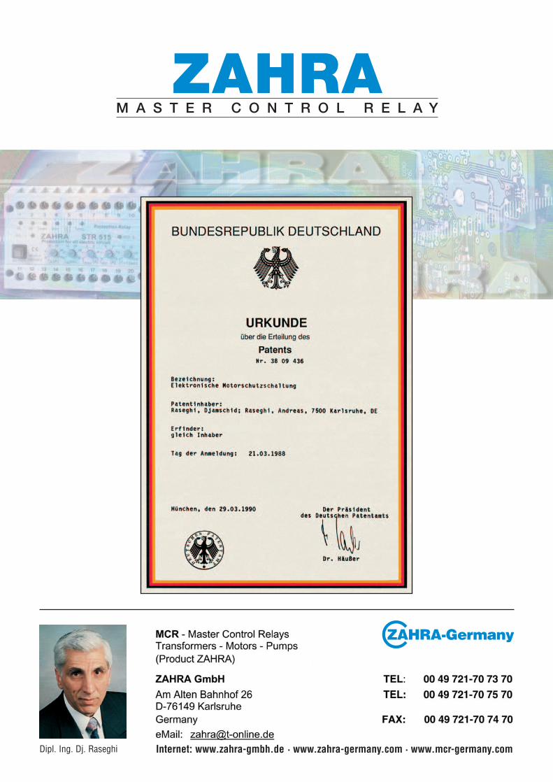
Dipl. Ing. Dj. Raseghi Internet: www.zahra-gmbh.de · www.zahra-germany.com · www.mcr-germany.com
MCR
Master Control Relay / Transformers – Motors – Pumps –Control Relay (Product ZAHRA)
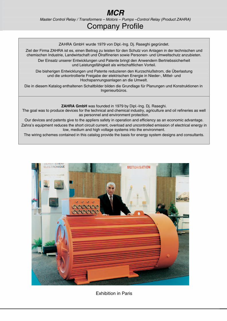
Company Profile
ZAHRA GmbH wurde 1979 von Dipl.-Ing. Dj. Raseghi gegründet.
Ziel der Firma ZAHRA ist es, einen Beitrag zu leisten für den Schutz von Anlagen in der technischen und chemischen Industrie, Landwirtschaft und Ölraffinerien sowie Personen- und Umweltschutz anzubieten.
Der Einsatz unserer Entwicklungen und Patente bringt den Anwendern Bertriebssicherheit und Leistungsfähigkeit als wirtschaftlichen Vorteil.
Die bisherigen Entwicklungen und Patente reduzieren den Kurzschlußstrom, die Überlastung und die unkontrollierte Freigabe der elektrischen Energie in Nieder-, Mittel- und
Hochspannungsanlagen an die Umwelt.
Die in diesem Katalog enthaltenen Schaltbilder bilden die Grundlage für Planungen und Konstruktionen in Ingenieurbüros.
ZAHRA GmbH was founded in 1979 by Dipl.-Ing. Dj. Raseghi. The goal was to produce devices for the technical and chemical industry, agriculture and oil refineries as well
as personnel and environment protection. Our devices and patents give to the appliers safety in operation and efficiency as an economic advantage.
Zahra’s equipment reduces the short circuit current, overload and uncontrolled emission of electrical energy in low, medium and high voltage systems into the environment.
The wiring schemes contained in this catalog provide the basis for energy system designs and consultants.
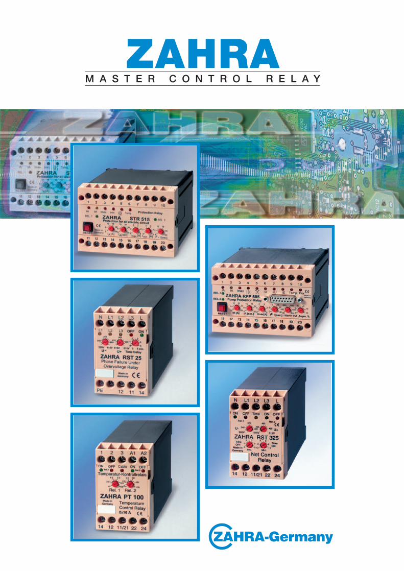
RST 25 RST 35 RST 38
PT 100 STR 515
Exhibition in Paris

MCR – Master Control Relay / Transformers – Motors – Pumps –Control Relays (ZAHRA Products)
Yesterday and today
The usage of simple bimetal relay can never guarantee full protection for electrical systems, because their exact adjustment is impossible and their function depends strongly on the ambient temperature. Countless desasters and economical damages are caused worldwide by these types of relays specially in the low and middle voltage range. The adjustment of bimetal fuses in the low voltage range is at the edge of adjustability, but on from middle voltage ranges totally impossible.
The founder of ZAHRA GmbH has already published technical briefs about this problem in 1988 in a number of technical magazines in Western Germany. It should be remembered, that, tough bimetal relays are cheap by nature, the desastrous economical effects in cases of malfunction in the moment of protection is required (either by misadjustment or by mechanical wear) and stand by no means in relation to their low acquisition price.
The usage of modern protection relays, either on an analog or digital basis, is therefore a must for equipping new and re-equipping existing systems.
The main difference between electromechanical and fully electronic protection relays lies in the fact, that electronic devices use current transformers for the low voltage range and voltage transformers for the middle voltage range, of which both provide a high degree of precision and reliability.
The founder of ZAHRA GmbH, Mr. Dipl.-Ing. Djamschid Raseghi, started his researches about electronical relays back in 1962. These devices were at that point already capable of monitoring phase failure, phase sequence, over- and undervoltage. At the same time, he introduced a special circuit to detect induced reverse voltage and ( feedback voltage ). Three years later, this system was adapted to supervise the function of transformers, motors and pumps. By this means, the monitoring of currents became split into two separate phases, i.e. the startup current and normal operation current, which increased the system’s safety dramatically. His researches were acclaimed all over Europe. With the progress of technology and the increasing usage of semiconductor and digital technologies, he was able to enhance his supervision devices, so that they became able to detect short circuits shortly before they occur. From the beginning his aims were the utmost protection for persons and systems, specially in cases of desasters and fire. Even more aspects found their way into the already existing system, so earth faults, earth leakage faults, cable breaks and neutral wire breaks could be detected. Protection devices of today are required to detect such errors as early as possible, preferably before they really occur, special techniques are needed to ensure such excellent protection. Also, the operating and maximum current, according to (I 2 t), must be considered. This can be very easily adjusted at ZAHRA devices, in contrary to bimetal relays. Our products are exposed at the Hannover Fair since 1985 and have found extraordinary good resonance worldwide from the beginning. ZAHRA holds a number of patents and since 1988, ZAHRA devices were also manufactured for external companies, e.g. ABB, AEG, Bender, Bohncke, Müller Weingarten, Sermes and SIBA and were also produced in license by Dold and by MES Dubai for the Emirate markets. Feedback from our customers is thoroughly positive and ZAHRA devices operate today in a vast number of applications on all continents. Some special applications, e.g. special pump systems, require concepts different to the star/delta model, because the star/delta model can cause severe damages. In these cases, the voltage of 3 x 400V is up-transformed to 3 x 1000V and over a startup transformer with applied 70 % of the nominal voltage to the consumer. Later this startup transformer is shorted. ZAHRA devices are, among others, compatible to SPC and PLC systems. By today’s technology little changes in the design of the CT’s enable the production of primary relays, that are self-supplied. ZAHRA is a worldwide pioneer in this field and introduces with this catalog the new OCR and RPG series, which realize this concept.

MCR – Master Control Relay / Transformers – Motors – Pumps –Protection Relay
Gestern und heute
Die Verwendung von einfachen Bimetallauslösern kann niemals einen Vollschutz für elektrische Anlagen gewährleisten, weil deren genaue Einstellung schwierig ist und ihre Funktion stark von der Umgebungstemperatur abhängt. Die Unfälle und wirtschaftlichen Schäden, die durch diese Auslösertypen weltweit im Niederspannungs- und insbesondere Mittelspannungsbereich bewirkt werden, sind unzählig. Eine Einstellung von Bimetallauslösern unter Spannung bei Niederspannung ist gerade noch möglich, aber schon bei mittleren Spannungen nicht mehr realisierbar.
Der Gründer der Firma ZAHRA hat bereits 1988 in mehreren technischen Zeitschriften der Bundesrepublik Deutschland über diese Problematik ausführliche Artikel verfasst. Es sollte nicht vergessen werden, dass Bimetallauslöser der Anschaffung nach zwar preisgünstig sind, sich jedoch die enormen wirtschaftlichen Schäden bei Ausfall im Fehlerfall durch Falscheinstellungen oder mechanischem Verschleiß keinesfalls mehr rechnen lassen. Der Einsatz moderner Schutzrelais - auf analoger oder digitaler Basis - ist daher ein Muss für die Ausrüstung neuer und die Umrüstung älterer Anlagen. Der Hauptunterschied zwischen elektromechanischen Bimetall- und vollelektronischen Schutzrelais liegt darin, dass die elektronischen Modelle im Niederspannungsbereich Stromwandler und im Mittelspannungsbereich Spannungswandler verwenden, die eine sehr hohe Zuverlässigkeit bieten.
Der Gründer der Firma ZAHRA GmbH, Herr Dipl.-Ing. Djamschid Raseghi, begann mit seinen Forschungen über elektronische Relais bereits 1962, welche schon zum damaligen Zeitpunkt Phasenausfall, Phasenfolge, Unter- und Überspannung erkennen und melden konnten und stellte zeitgleich auch eine spezielle Schaltung zur Erkennung induzierter Rückspannung vor.
Drei Jahre später erweiterte er dieses System zur Überwachung von Transformatoren, Elektromotoren und Pumpen und trennte die Überwachung in zwei Phasen auf, der separaten Überwachung des Anlauf- und Nennstroms, um den Kurzschlussstrom in jedem Fall zu reduzieren. Diese Technologie fand in Europa durchgehend positive Resonanz. Mit dem Fortschritt der Technik und dem zunehmenden Einsatz von Halbleiter- und digitalen Technologien war es ihm möglich, die Schaltung soweit zu verfeinern, dass sie in der Lage war, sich anbahnende Kurzschlüsse bereits vor ihrem eigentlichen Auftreten zu erkennen.
Sein Ziel war von Anfang an der größtmögliche Schutz von Personen und Anlagen, insbesondere im Katastrophen- und Brandfall. Hinzu kam, dass weitere Aspekte in das bereits vorhandene System mit einflossen, wie etwa die Erkennung von Nullleiterbrüchen, Fehlerströmen, Leitungsbrüchen, Erdschlüssen und Schutzleiterunterbrechungen. An heutige Schutzgeräte ist die Anforderung gestellt, derartige Systemfehler möglichst vorzeitig, also vor dem Zeitpunkt ihres Auftretens zu erkennen, was besondere Schaltungstechnologien erfordert. Außerdem muss der (bei ZAHRA-Geräten im Gegensatz zu Bimetallauslösern sehr einfach einstellbare) Nenn- bzw. Maximalstrom nach thermischen Charakteristiken (I
2t) berücksichtigt werden.
Unsere Produkte werden seit 1985 auf der Hannover-Messe ausgestellt und haben seitdem breites Interesse gefunden. ZAHRA besitzt hierzu eine Reihe von Patenten, und seit 1988 wurden ZAHRA-Geräte auch für Fremdfirmen wie etwa ABB, AEG, Bender, Bohncke, Müller Weingarten, Sermes und SIBA produziert und unter anderem von Dold in Lizenz und von MES Dubai für den Emirate-Markt hergestellt. Die Resonanz ist durchgehend positiv, und ZAHRA-Geräte werden heute in einer sehr großen Anzahl von Anwendungen eingesetzt. Unter anderem ist es erforderlich, bei einigen besonderen Applikationen, etwa bestimmten Pumpensystemen, von der klassischen Stern-/Dreieck-Technik Abstand zu nehmen, weil sie in manchen Fällen Schäden verursachen kann. In diesen Fällen wird die Spannung von 3 x 400V auf 3 x 1000V hochtransformiert, und über einen Anlasstrafo mit 70 % der Nennspannung hochgefahren, wobei danach dieser Anlasstrafo unterbrechungslos überbrückt wird.
ZAHRA - Geräte sind auch für SPC- und PLC-Systeme bestens geeignet. Mit heutiger Technik lassen sich durch kleine Entwurfsänderungen an den Stromwandlern Primärrelais realisieren, die keine Fremdspeisung mehr benötigen.
ZAHRA ist auf diesem Sektor weltweit Pionier und hat diesbezüglich neue Geräte unter der Typenbezeichnung OCR und RPG im Programm.
MCR – Master Control Relay / Transformers – Motors – Pumps –Control Relay (Product ZAHRA)
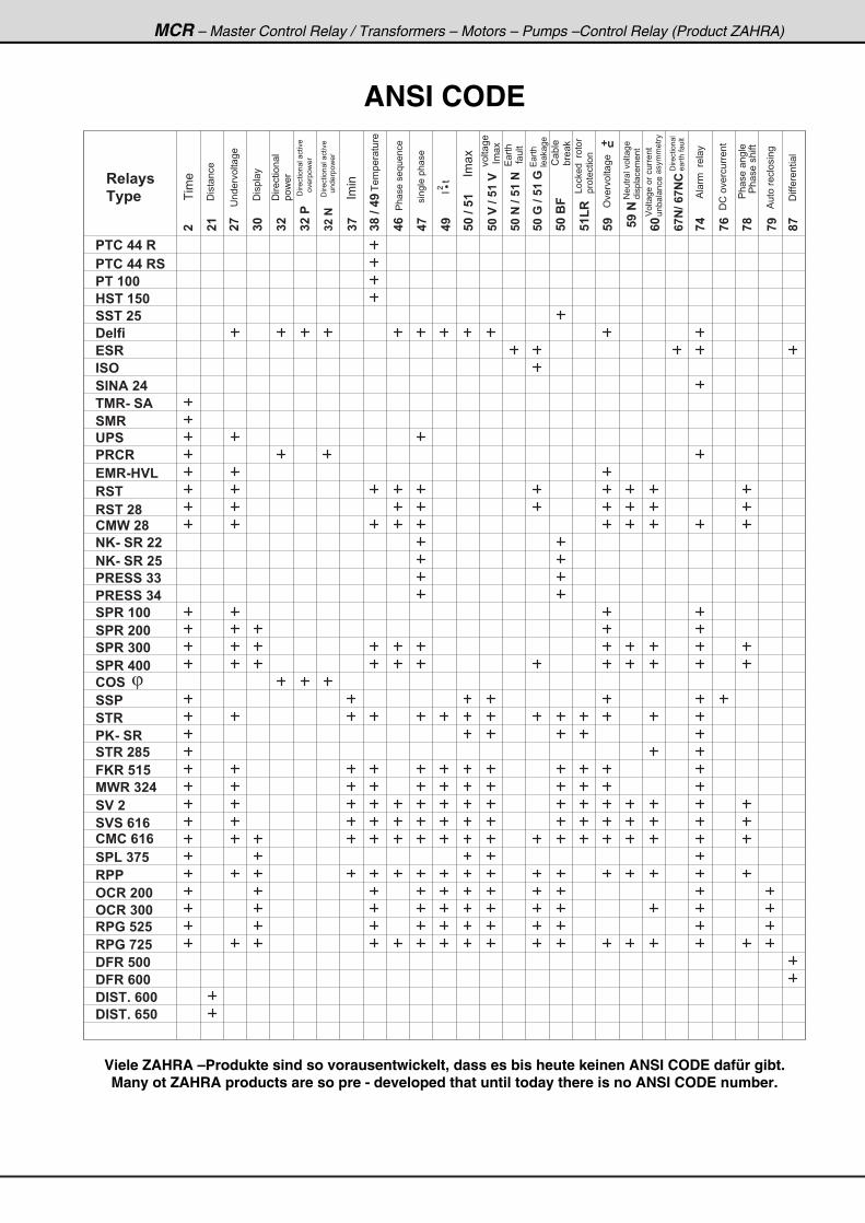
ANSI CODE
� ��
��
��
��
����
����
��
�����
�
��
��
������
����������
����������
����������
�����
��
�
��� ���
��
�
��
�
� � � � � �
� � � �
� � � � � � � �
� � � � � � � � �
� � � � � �
� � � � � � �
� � � � � �
� � � �
! � �
" � #
� " � $ � � �
� � � �
� % � & � � $
� % �
' � �
! % � & � � (
� � �
� � ! � � � � �
� � ! � � � � �
� � � � � � �
� � � � � � �
� � � � � � �
� � � � � � �
� # � � �
% ) � � � � �
� � � �
� � � � �
� � ( � � � �
� � � � �
� % ) � �
� * & � � � � � �
� * & � � � � � �
� � �
� * & � � �
� � �
� � � � � �
� � �
# � � � � � �
# � � � � � �
� � � � � � �
� � � � � � �
� � � � � � �
� � � � � �
� " � � + � � �
� " � � + � � �
� % � � �
�����
� * � � � � �
�
��(�
�����
�
������� ��
� �
��������� ��
���
�
���� ���
����� �
�������� �
����
�������� �� ����
�������� �� ����
����
����� ���
�� �����������
�� �
��� ��
��� ��
� ��
�� ���
� ���
�� ��
! "��
"�
#��� ����� ��
����� ������
$��� ����������
��" � ���
%� ����� �
�!��������
�� ��� ����
%������������
��������� �
�������� �
� ���� ���
������
��������
&�� �������
���������
�� ��������
'���� ��
� �
�������
Viele ZAHRA –Produkte sind so vorausentwickelt, dass es bis heute keinen ANSI CODE dafür gibt. Many ot ZAHRA products are so pre - developed that until today there is no ANSI CODE number.
MCR Master Control Relays / Transformers – Motors – Pumps –Control Relays (Product ZAHRA)
© Copyright 1979, 2003 by Zahra GmbH, Germany. All rights reserved. This document may not, in whole or in part, be copied, photocopied, reproduced, translated, transmitted or reduced to any electronic or printed medium whithout prior consent in writing from Zahra GmbH
Table Of Contents
Relay Page Relay Page
1. Breaker- and Fuse Control Schaltkontakt - Kontrollrelais FCR 3, PFCR 63, FCR 345 .......................... 1-2
2. Temperature Control Temperatur - Überwachungsrelais PTC 44 R & PTC 44 RS with PTC sensor PT 100 & HST 150 with PT100 sensor .......... 3-4
3. Balance Control Balance - Kontrollrelais BLC 24................................................................5
4. Standstill Relay / Stillstandsrelais
SCR 45...............................................................5
5. Star/ Delta - Stern- / Dreieck - Relais SDR 24, CMC 616........................................6, 43
6. Rotation Direction Fixing Automatisches Wendepolrelais RCR 25...............................................................6
7. Loop Current - Schleifenstromrelais SST 25 ..............................................................7
8. Level Control & Dry Run Pegelregler und Trockenlaufschutzrelais PLC 34, DRY 22, NKR 420, NKR 620 ......... 7-10
9. Filling & Emptying Niveaukontrollrelais NKR 420, NKR 620 ...................................... 8-10
10. Pump Control Pumpenschutzrelais Delfi 22,Delfi 44,Delfi 45,Delfi 88, Delfi 150 ... 10-12 RPP 385, RPP 485, RPP 685 ........................ 45-47 STR 313, STR 515, STR 525,STR 616 ......... 39-40
11. RPP Indicator for RPP 685 & RPP 688..... Anzeigemodul.........................................50
12. Earth Leakage & Fault Erdschlussrelais ESR 26, ESR 36, ESR 88, ESR 100, ESR 200, ESR 400, ESR 600, ISO 25, ISO 35 .......... 13-17
13. Isolation Control Relay Isolationsüberwachungsrelais
ISO 25, ISO 35..............................................17
14. Alarm Relay -Alarmrelais SINA 24.........................................................18
15. Time Relay – Zeitrelais TIC 24, AXI 24, TMR 235, TMR 236, TMR 240, SA 24, SMR 24 ......................... 18-19
16. Undervoltage Control Untersp.relais UPS 230, UPS 400 ............ 19
17. Reverse-Power Control Relay Rückleistungsrelais PRCR 88, PRCR 35, PRCR 620 ................20-21
18. Power Failure Control (Line Control ) Netzausfallkontrollrelais EMR 45, HVL 240 - RST 325 .................... 22, 27
19. Phase Failure/ Sequence, Under & Overvoltage, Asymmetry, Temperature, Earth Leakage, Dry Run, Motor Protection and VT Control Relay Phasenausfall, Phasenfolge, Unter - und Überspannung, Erdschluss , Trockenlauf – Assymmetrierelais und Sp.Wandler - Kontrollrelais
RST 22, RST 25, RST 26, RST 28, RST 33, RST 35, RST 38, RST 46, RST 88, RST 285, RST 325, CMW 28, STR 285 ............22-28, 37
20. Cable Break & Phase Failure, CT Control Relay (current principle) Leitungsbruch - , Phasenausfall -, Stromwandler - Kontrollrelais (Stromprinzip)
NK-SR 22 (working current principle) with relay output NO ............................................ 29 NK-SR 25 (holding-current principle) with relay output NC............................................. 29 PK-SR........................................................... 38 OCR Series .............................................51-56 RPG 525, RPG 725.................................57-59 STR Series ..............................................36-40
21. Cable Break & Phase Failure, CT Control Relay (current principle) & Instantaneous Trip Leitungsbruch -, Phasenausfall -, Stromwandler - Kontrollrelais (Stromprinzip) PRESS 33 (working current principle) with relay output NO................................................ 30 PRESS 44 (holding-current principle) with relay output NC................................................ 30
22. Press Control - Presskontrollrelais PRESS 33, PRESS 44 .................................... 30 MWR 324......................................................... 41
MCR Master Control Relays / Transformers – Motors – Pumps –Control Relays (Product ZAHRA)
© Copyright 1979, 2003 by Zahra GmbH, Germany. All rights reserved. This document may not, in whole or in part, be copied, photocopied, reproduced, translated, transmitted or reduced to any electronic or printed medium whithout prior consent in writing from Zahra GmbH
Table Of Contents
Relay Page Relay Page
23. Power Factor Control - Cos Relais Cos 20, Cos 25, Cos 400 .............. 34-35
24. Torque Monitoring Relay Wirkleistungs - Kontrollrelais Delfi Series.............................................. 10-12 Cos 20, Cos 25, Cos 400 .............. 34-35
25. Under-&Overvoltage Control Unter - und Überspannungsrelais
DC: SPR 100, SPR 200 (digital) ..........................31 AC: SPR 300 (digital), SPR 400 (digital) ....... 32-33
26. Under- & Overcurrent Control Unter - und Überstromrelais
SSP Series, STR 15, STR 25, STR 35, STR 45, PK-SR, FKR 515, STR 313, STR 515, STR 525, STR 616, MWR 324 ....................................... 35-41 OCR 244, OCR 245, OCR 285, OCR 288, OCR 344, OCR 345, OCR 385, OCR 388 ..... 51-56
27. Transformer/ Motor/ Pump Control FKR 515, STR 313, STR 515, STR 525, STR 616, MWR 324, SV2, SVS 616, CMC 616, OCR... 38-56
28. Energy Management Control Spitzenlastüberwachungsrelais
SPL 375 ........................................................44
29. Master Board Control- Relaismodul MBC 8, MBC 18............................................... 50
30. Multifunction Protection Relay with Teleswitching Multifunktions – Schutzrelais mit Fernsteuerung CMC 616 - RPP 685 – RPP 688 – ...... 43, 47, 48
31. Primary Relay Without Power Supply Primärrelais ohne Eigenversorgung RPG 525, RPG 725 ....................................57-58
32. Differential Relay - Differentialrelais DFR 500, DFR 600, LDR 600 60-61
33. Distance Relay - Distanzrelais Distance 600, Distance 650 ....................62-63
34. Standard ZAHRA CT’s Stromwandler ZW 315, ZW 412.............................................. 64
35. Special ZAHRA CT’s Spezial ZAHRA Stromwandler CT 20, CT 60, CT 150 ..................................... 64
36. Inrush Curve Anlaufkurve ................................................ 65
37. Trip Characteristics Auslösekennlinien .............................66
ZAHRA Prod ucts h ave a guaran tee of 5 years and are in accor dance with VDE 0110 and IEC 949.
Every ZAHRA device is delivered with an extensive operation manual with application examples. We also produce customized relays and adapters for your specific application, as we have done. for our clients Mercedes Benz and e.g 25 T press systems in the past. Many models can be delivered with active or
passive output relays.
ZAHRA-Pro dukte h aben eine Garan tiezeit v on 5 Jahren und en tsprech en VDE 0110 so wie IEC 949.
Mit jedem Gerät wird eine ausführliche, informative Gebrauchsanweisung mit Schaltbeispielen mitgeliefert. Außer den Standardmodellen liefern wir auch kundenspezifische Relais und Anpassungen
für Ihre Anforderungen, wie wir das auch für Mecedes Benz mit z:B: 25 T – Pressanlagen in der Vergangenheit getan haben. Zahlreiche Geräte können mit aktiven oder passiven Ausgangsrelais
geliefert werden.
Relay Page Relay Page
23. Power Factor Control - Cos Relais Cos 20, Cos 25, Cos 400 .............. 34-35
24. Torque Monitoring Relay Wirkleistungs - Kontrollrelais Delfi Series.............................................. 10-12 Cos 20, Cos 25, Cos 400 .............. 34-35
25. Under-&Overvoltage Control Unter - und Überspannungsrelais
DC: SPR 100, SPR 200 (digital) ..........................31 AC: SPR 300 (digital), SPR 400 (digital) ....... 32-33
26. Under- & Overcurrent Control Unter - und Überstromrelais
SSP Series, STR 15, STR 25, STR 35, STR 45, PK-SR, FKR 515, STR 313, STR 515, STR 525, STR 616, MWR 324 ....................................... 35-41 OCR 244, OCR 245, OCR 285, OCR 288, OCR 344, OCR 345, OCR 385, OCR 388 ..... 51-56
27. Transformer/ Motor/ Pump Control FKR 515, STR 313, STR 515, STR 525, STR 616, MWR 324, SV2, SVS 616, CMC 616, OCR... 38-56
28. Energy Management Control Spitzenlastüberwachungsrelais
SPL 375 ........................................................44
29. Master Board Control- Relaismodul MBC 8, MBC 18............................................... 50
30. Multifunction Protection Relay with Teleswitching Multifunktions – Schutzrelais mit Fernsteuerung CMC 616 - RPP 685 – RPP 688 – ...... 43, 47, 48
31. Primary Relay Without Power Supply Primärrelais ohne Eigenversorgung RPG 525, RPG 725 ....................................57-58
32. Differential Relay - Differentialrelais DFR 500, DFR 600, LDR 600 60-61
33. Distance Relay - Distanzrelais Distance 600, Distance 650 ....................62-63
34. Standard ZAHRA CT’s Stromwandler ZW 315, ZW 412.............................................. 64
35. Special ZAHRA CT’s Spezial ZAHRA Stromwandler CT 20, CT 60, CT 150 ..................................... 64
36. Inrush Curve Anlaufkurve ................................................ 65
37. Trip Characteristics Auslösekennlinien .............................66
MCR – Master Control Relay / Transformers – Motors – Pumps –Protection Relay
FCR 33
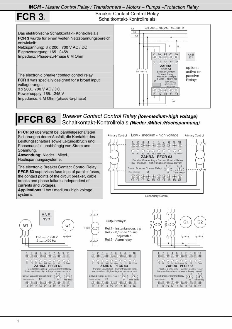
Breaker Contact Control Relay Schaltkontakt-Kontrollrelais
Das elektronische Schaltkontakt- Kontrollrelais FCR 3 wurde für einen weiten Netzspannungsbereich entwickelt: Netzspannung: 3 x 200...700 V AC / DC Eigenversorgung: 165...245V Impedanz: Phase-zu-Phase 6 M Ohm
The electronic breaker contact control relay FCR 3 was specially designed for a broad input voltage range: 3 x 200…700 V AC / DC. Power supply: 165…245 V Impedance: 6 M Ohm (phase-to-phase)
& (
& �
& )
) � � � � * * + + + + + , * % ! � - � . * + + + / * � 0 1* �
& #
� � � � � � � 2 �
� � � � � �
� � � � �
3 � � � 2
( / %
% # 4 �
� 5 5 5 �
& ( ' #
, $ � � $
6 � � � ! � � � � �
� � � � � $
7 � � � � � � $ � � � � � 2
) � � � � * * � + + � , * * � $ � % !
� � � � � � � � � � � 2 �
( / 8 � + + + � � . 8 � $ � % !
3 � � � 2 ( / %
& ( & � & ) % ( % �
� ( � � � ) ( ( ( .
& � & ) ' 9 9
7 � � � � � � : � � � �
! � � � � � � 3 � � �
PFCR 63 Breaker Contact Control Relay (low-medium-high voltage) Schaltkontakt-Kontrollrelais (Nieder-/Mittel-/Hochspannung)
PFCR 63 überwacht bei parallelgeschalteten Sicherungen deren Ausfall, die Kontakte des Leistungsschalters sowie Leitungsbruch und Phasenausfall unabhängig von Strom und Spannung. Anwendung: Nieder-, Mittel-, Hochspannungssysteme.
The electronic Breaker Contact Control Relay PFCR 63 supervises fuse trips of parallel fuses, the contact points of the circuit breaker, cable breaks and phase failures independent of currents and voltages. Applications: Low / medium / high voltage systems.
& � � � - � � � � � � � � � - � � � � � � � � � � �
4 � � � � � � � ! � � � � �
� � � � � ! � � � � �� � � � � ! � � � � �
( � ) . 8 / , ; < ( *
( ( ( � ( ) ( . ( 8 ( / ( , ( ; ( < � *
7 � � � � � � : � � � �
* 8
( .
� )
9 ( 9 ) 3 � � + (
! � � � � � � 6 � � � ! � � � � � � 3 � � �
9 �
, $ � � $ � � � � � � � � �
3 � � + � % � � 9 . 9 8
* 8
( .
� )
� 3 � � � � � � � � �
� � � � � � ! � � � � � � � � � � - � ! � � � � � ! � � � � � � 3 � � �
� � � � 9 /
� � � � - � � � � � � � � - � � � � � � � � � � � � � � � � � � � � � � �
: (
( ( * + + + + + + + + + ( * * * � $
) + + + + + + + + + . * * � 0 1
� ���(
� ����
: (� ' � � � � � � � � � � 2
3 � � + ( � - � � � � � � � � � � � � � � � �
3 � � + � � - � * = ( � � � � � � ( 8 � � � �
� � � � � � � � � � � � � � > � � � " � � +
3 � � + ) � - � % � � � � � �
� � � �
: �
: (
% # 4 �
� 5 5 5 �
( � ) . 8 / , ; < ( *
( ( ( � ( ) ( . ( 8 ( / ( , ( ; ( < � *
7 � � � � � � : � � � �
* 8
( .
� )
9 ( 9 ) 3 � � + (
! � � � � � � 6 � � � ! � � � � � � 3 � � �
9 �
, $ � � $ � � � � � � � � �
3 � � + � % � � 9 . 9 8
* 8
( .
� )
� 3 � � � � � � � � �
� � � � � � ! � � � � � � � � � � - � ! � � � � � ! � � � � � � 3 � � �
� � � � 9 /
� � � � - � � � � � � � � - � � � � � � � � � � � � � � � � � � � � � � �
1
MCR – Master Control Relay / Transformers – Motors – Pumps –Control Relay (Product ZAHRA)
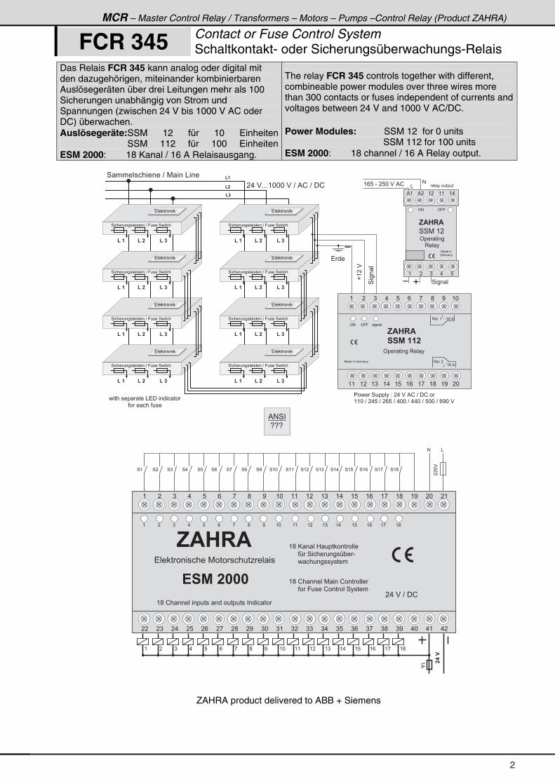
FCR 345 Contact or Fuse Control System Schaltkontakt- oder Sicherungsüberwachungs-Relais
Das Relais FCR 345 kann analog oder digital mit den dazugehörigen, miteinander kombinierbaren Auslösegeräten über drei Leitungen mehr als 100 Sicherungen unabhängig von Strom und Spannungen (zwischen 24 V bis 1000 V AC oder DC) überwachen. Auslösegeräte:SSM 12 für 10 Einheiten SSM 112 für 100 EinheitenESM 2000: 18 Kanal / 16 A Relaisausgang.
The relay FCR 345 controls together with different, combineable power modules over three wires more than 300 contacts or fuses independent of currents and voltages between 24 V and 1000 V AC/DC. Power Modules: SSM 12 for 0 units SSM 112 for 100 units ESM 2000: 18 channel / 16 A Relay output.
4��� �
( �
( �
( �
-
�(��$
� � � � � � � � � � � & � � � � � � � � � �
� � � � � � � � � � �
4 � � � � � � � � � � � � ? � 7 � � � & � � �
� � �
4 � � � ��
-
( / 8 � - � � 8 * � $ � % ! � � � � � � � � � �
#
&
' # ' 9 9
' � � � � � �
3 � � �
, $ � � $ �
% ( ( � ( (% � ( .
( ) . 8�
7 � � � � �
: � � � �
( � �( � � ( � �
4 � � � � � � � � � � � � � � � � ? � 9 � � � � 4 � � � � �
� � � � � � �
� . � $ + + + ( * * * � $ � ? � % ! � ? � � !
( � �( � � ( � �
4 � � � � � � � � � � � � � � � � ? � 9 � � � � 4 � � � � �
� � � � � � �
( � �( � � ( � �
4 � � � � � � � � � � � � � � � � ? � 9 � � � � 4 � � � � �
� � � � � � �
( � �( � � ( � �
4 � � � � � � � � � � � � � � � � ? � 9 � � � � 4 � � � � �
� � � � � � �
( � �( � � ( � �
4 � � � � � � � � � � � � � � � � ? � 9 � � � � 4 � � � � �
� � � � � � �
( � �( � � ( � �
4 � � � � � � � � � � � � � � � � ? � 9 � � � � 4 � � � � �
� � � � � � �
( � �( � � ( � �
4 � � � � � � � � � � � � � � � � ? � 9 � � � � 4 � � � � �
� � � � � � �
( � �( � � ( � �
4 � � � � � � � � � � � � � � � � ? � 9 � � � � 4 � � � � �
� � � � � � �
4 4 7 � ( � �
' #
, $ � � $ �
� � % � � � �
' 9 9
3 � � + � �
( / � %
3 � � + � ( ( / � %
� � � � �
7 � � � � � � : � � � �
' � � � � � � � 3 � � �
� � � � � 4 � � � � � � 2 � � . � $ � % ! � ? � � ! � �
( ( * � ? � � . 8 � ? � � / 8 � ? � . * * � ? � . . * � ? � 8 * * � ? � / < * � $
( � ) . 8 / , ; < ( * ( ( ( � ( ) ( . ( 8 ( / ( , ( ;
����
(%
' � � � � �
� � � � �
� � � � � 4 � � � � �
( � ) . 8 / , ; < ( * ( ( ( � ( ) ( . ( 8 ( / ( , ( ; ( < � * � (
� � � ) � . � 8 � / � , � ; � < ) * ) ( ) � ) ) ) . ) 8 ) / ) , ) ; ) < . * . ( . �
! � % � � � � �
� � � � � � � � � � � � 7 � � � � � � � � 1 � � � �
( ; � @ � � � 0 � � � � � � � � � �
� � � � � � A � 4 � � � � � � � � A " � -
� � � � � � � � � � � � � � � � � � �
( ; � ! � � � � � � 7 � � � ! � � � � � � �
� � � � � � � � 9 � � � � ! � � � � � � 4 � � � � �
� . � $ � ? � � !
( � ) . 8 / , ; < ( * ( ( ( � ( ) ( . ( 8 ( / ( , ( ;
( ; � ! � � � � � � � � � � � � � � � � � � � � � � � � � � � � � � �
( � ) . 8 / , ; < ( *
( ( ( � ( ) ( . ( 8 ( / ( , ( ; ( < � *
, $ � � $
4 ( 4 � 4 ) 4 . 4 8 4 / 4 , 4 / 4 < 4 ( * 4 ( ( 4 ( � 4 ( ) 4 ( . 4 ( 8 4 ( / 4 ( , 4 ( ;
# &
��*$
% # 4 �
� 5 5 5 �
ZAHRA product delivered to ABB + Siemens
2
MCR – Master Control Relay / Transformers – Motors – Pumps –Protection Relay
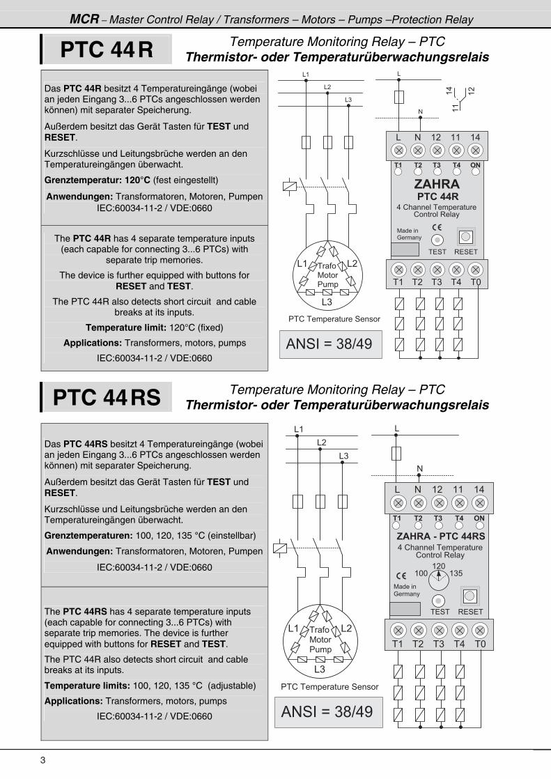
PTC 44 R Temperature Monitoring Relay – PTC Thermistor- oder Temperaturüberwachungsrelais
Das PTC 44R besitzt 4 Temperatureingänge (wobei an jeden Eingang 3...6 PTCs angeschlossen werden können) mit separater Speicherung.
Außerdem besitzt das Gerät Tasten für TEST und RESET.
Kurzschlüsse und Leitungsbrüche werden an den Temperatureingängen überwacht.
Grenztemperatur: 120°C (fest eingestellt)
Anwendungen: Transformatoren, Motoren, PumpenIEC:60034-11-2 / VDE:0660
The PTC 44R has 4 separate temperature inputs (each capable for connecting 3...6 PTCs) with
separate trip memories.
The device is further equipped with buttons for RESET and TEST.
The PTC 44R also detects short circuit and cable breaks at its inputs.
Temperature limit: 120°C (fixed)
Applications: Transformers, motors, pumps
IEC:60034-11-2 / VDE:0660
&
#
& (
& �
& )
& ( & �
& )
& # ( � ( ( ( .
� �� �
, $ � � $
� �� �
� ( � ) � . � *� �
7 � � � � �
: � � � �
# �
� � � � � � � �
� � �
7 � � �
� � � �
((
(.
(�
� � ! � � � � � � � � � � 4 � � � �
� � 4 � 3 � 4 � �
. � ! � � � � � � � � � � � � � � �
! � � � � � � 3 � � �
% # 4 � � B � ) ; ? . <
PTC 44 RS Temperature Monitoring Relay – PTC Thermistor- oder Temperaturüberwachungsrelais
Das PTC 44RS besitzt 4 Temperatureingänge (wobei an jeden Eingang 3...6 PTCs angeschlossen werden können) mit separater Speicherung.
Außerdem besitzt das Gerät Tasten für TEST und RESET.
Kurzschlüsse und Leitungsbrüche werden an den Temperatureingängen überwacht.
Grenztemperaturen: 100, 120, 135 °C (einstellbar)
Anwendungen: Transformatoren, Motoren, Pumpen
IEC:60034-11-2 / VDE:0660
The PTC 44RS has 4 separate temperature inputs (each capable for connecting 3...6 PTCs) with separate trip memories. The device is further equipped with buttons for RESET and TEST.
The PTC 44R also detects short circuit and cable breaks at its inputs.
Temperature limits: 100, 120, 135 °C (adjustable)
Applications: Transformers, motors, pumps
IEC:60034-11-2 / VDE:0660
&
#
& (
& �
& )
& ( & �
& )
& # ( � ( ( ( .
� �� �
, $ � � $ � & � � � � � � � � �
. � ! � � � � � � � � � � � � � � �
! � � � � � � 3 � � �
� �� �
� ( � ) � . � *� �
7 � � � � �
: � � � �
# �
� � 4 �
( ) 8( * *
( � *
� � �
7 � � �
� � � �
� � ! � � � � � � � � � � 4 � � � �
3 � 4 � �
% # 4 � � B � ) ; ? . <
3
MCR – Master Control Relay / Transformers – Motors – Pumps –Control Relay (Product ZAHRA)
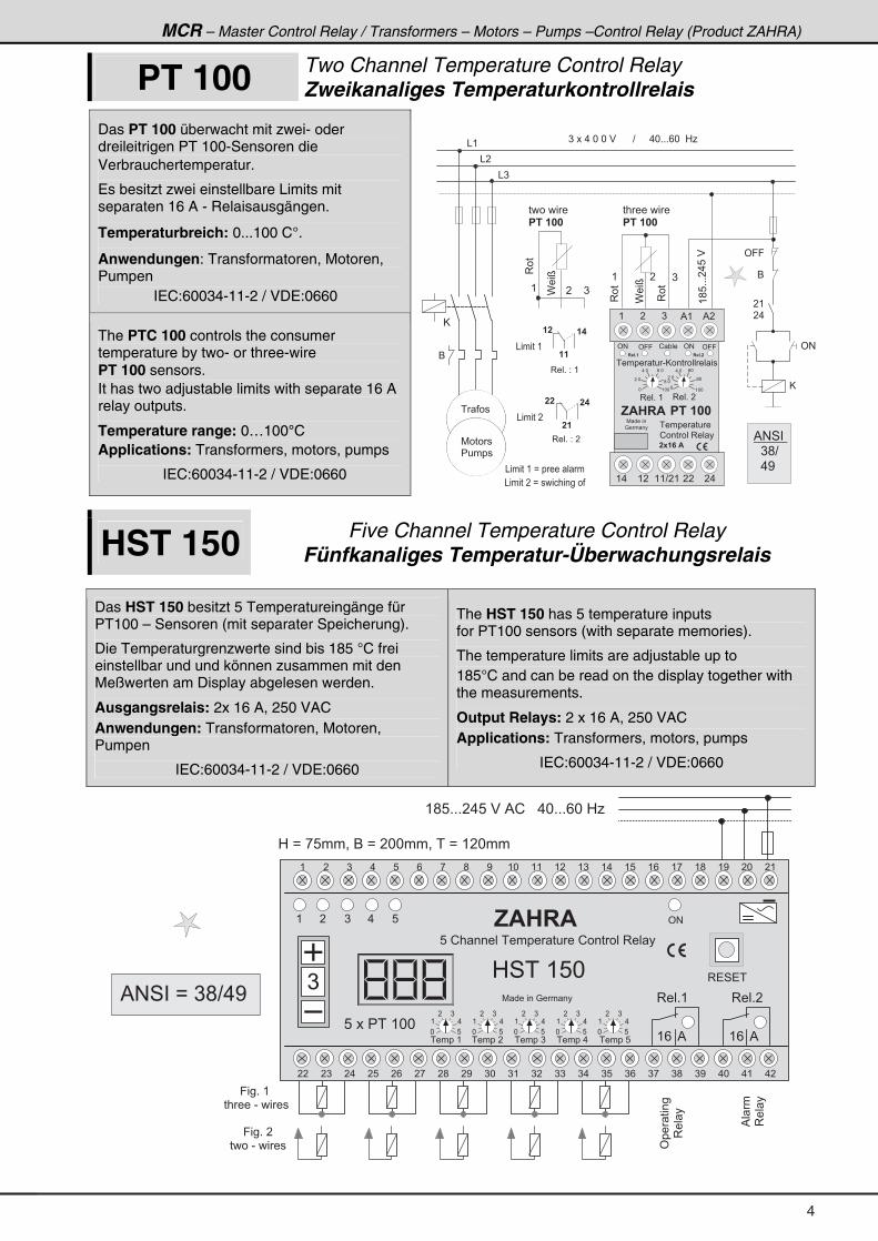
PT 100 Two Channel Temperature Control Relay Zweikanaliges Temperaturkontrollrelais
Das PT 100 überwacht mit zwei- oder dreileitrigen PT 100-Sensoren die Verbrauchertemperatur.
Es besitzt zwei einstellbare Limits mit separaten 16 A - Relaisausgängen.
Temperaturbreich: 0...100 C°.
Anwendungen: Transformatoren, Motoren, Pumpen
IEC:60034-11-2 / VDE:0660
The PTC 100 controls the consumer temperature by two- or three-wire PT 100 sensors. It has two adjustable limits with separate 16 A relay outputs.
Temperature range: 0…100°C Applications: Transformers, motors, pumps
IEC:60034-11-2 / VDE:0660
& (
& �
& )
6
) � � � . � * � * � $ � � � � � � ? � � � � � . * + + + / * � � 0 1 �
' 9 9
6
� (
� .
' #
@
� �
� � � �
3 � � + � 2 � (
� �
� � � �
3 � � + � 2 � �
& � � � � � (
& � � � � � �
� � � � � � � � �
� � � � � �
)
( �
3��
3��
C��D
( �
)
3��
C��D
� � � � � � � �
� � � � � �
(;8+++�.8�$
@
( . ( � ( ( ? � ( � � � .
� � � � � � � - @ � � � � � � � � � �
( ) % ( % �
' # ' 9 9! " � �
*
� *
. * / *
; *
3 � � + � ( 3 � � + � �
� � � � � � � � �
! � � � � � � 3 � � �
� - � � $
, $ � � $ � � � � � �
7 � � � � � �
: � � � �
( * * ( * **
� *
. * / *
; *
' 9 9 ' #
� � � + � � � � + �
�
� � � �
7 � � � �
� � � � �
& � � � � � ( � B � � � � � � �
& � � � � � � � B � � � � � � � � � � � �
% # 4 � �
� � ) ; ?
� � . <
HST 150 Five Channel Temperature Control Relay Fünfkanaliges Temperatur-Überwachungsrelais
Das HST 150 besitzt 5 Temperatureingänge für PT100 – Sensoren (mit separater Speicherung).
Die Temperaturgrenzwerte sind bis 185 °C frei einstellbar und und können zusammen mit den Meßwerten am Display abgelesen werden.
Ausgangsrelais: 2x 16 A, 250 VAC Anwendungen: Transformatoren, Motoren, Pumpen
IEC:60034-11-2 / VDE:0660
The HST 150 has 5 temperature inputs for PT100 sensors (with separate memories).
The temperature limits are adjustable up to 185°C and can be read on the display together with the measurements.
Output Relays: 2 x 16 A, 250 VAC Applications: Transformers, motors, pumps
IEC:60034-11-2 / VDE:0660
( � ) . 8 ' #
3 � � + (
3 � 4 � �
3 � � + �
( / % ( / %
'�� ����
3�� �
%� �
3�� �
, $ � � $
0 4 � � ( 8 *
8 � ! � � � � � � � � � � � � � � � ! � � � � � � 3 � � �
)
� � � � � (
( ; 8 + + + � . 8 � $ � % ! � � � . * + + + / * � 0 1
0 � B � , 8 � � = � 6 � B � � * * � � = � � � B � ( � * � �
9 � � + � (
� � � � � � - � � � � �
9 � � + � � �
� � � � - � � � � �
* 8
( .
� )
* 8
( .
� )
* 8
( .
� )
* 8
( .
� )
* 8
( .
� )
8 � � � � � � ( * *
7 � � � � � � : � � � �
� � � ) � . � 8 � / � , � ; � < ) * ) ( ) � ) ) ) . ) 8 ) / ) , ) ; ) < . * . ( . �
( � ) . 8 / , ; < ( * ( ( ( � ( ) ( . ( 8 ( / ( , ( ; ( < � * � (
� � � � � � � � � � � ) � � � � � . � � � � � 8
% # 4 � � B � ) ; ? . <
4
MCR – Master Control Relay / Transformers – Motors – Pumps –Protection Relay
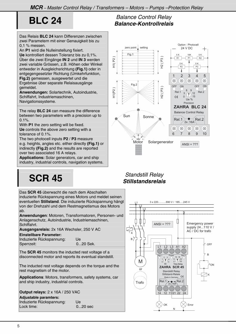
BLC 24 Balance Control Relay Balance-Kontrollrelais
Das Relais BLC 24 kann Differenzen zwischen zwei Parametern mit einer Genauigkeit bis zu 0,1 % messen. An P1 wird die Nulleinstellung fixiert. Ue kontrolliert dessen Toleranz bis zu 0,1%. Über die zwei Eingänge IN 2 und IN 3 werden zwei variable Grössen, z.B. Höhen oder Winkel entweder in Ausgleichsrichtung (Fig.1) oder in entgegengesetzter Richtung (Umkehrfunktion, Fig.2) gemessen, ausgewertet und die Ergebnise über separate Relaisausgänge gemeldet. Anwendungen: Solartechnik, Autoindustrie, Schiffahrt, Industriemaschinen, Navigationssysteme.
The relay BLC 24 can measure the difference between two parameters with a precision up to 0.1%. With P1 the zero setting will be fixed. Ue controls the above zero setting with a tolerance of 0.1%. The two photocell inputs P2 / P3 measure e.g. heights, angles etc. either directly (Fig.1) or indirectly (Fig.2) and the results are reported over two associated 16 A relays. Applications: Solar generators, car and ship industry, industrial controls, navigation systems.
� . � $ � � !
3 (
8 � @8 � @
8 � @8 � @
( * @
0(H���I
0��H��)�I
0(H����I
0��H��)�I
1 � � � � � � � � � � � � � � � � � � � �
9 � � + (
( ) .� 8
� � � J
3 � � + ( 3 � � + �
' #' 9 9 ' # ' 9 9
� � � � � � � �
, $ � � $ � � � ( � � � �
6 � � � � � ! � � � � � � 3 � � �
3 � � + ( 3 � � + �
� � � � ( / %
� �
3 �� (
� )
* ( 8
) ( �
/ <
9 � � + �
' � � � � � � 2 � � � � � � � � � �
4 � �4 � � � �
4 � � � � � � � � 7 � � �
/ , ; < ( *
% # 4 � � B � 5 5 5
SCR 45 Standstill Relay Stillstandsrelais
Das SCR 45 überwacht die nach dem Abschalten induzierte Rückspannung eines Motors und meldet seinen eventuellen Stillstand. Die induzierte Rückspannung hängt von der Drehzahl und dem Restmagnetismus des Motors ab. Anwendungen: Motoren, Transformatoren, Personen- und Anlagenschutz, Autoindustrie, Industriemaschinen, Schiffahrt. Ausgangsrelais: 2x 16A Wechsler, 250 V AC Einstellbare Parameter: Induzierte Rückspannung: Ue Sperrzeit: 0...20 Sek.
The SCR 45 monitors the inducted rest voltage of a disconnected motor and reports its eventual standstill. The inducted rest voltage depends on the torque and the rest magnetism of the motor.
Applications: Motors, transformers, safety systems, car and ship industry, industrial controls. Output relays: 2 x 16A / 250 VAC Adjustable paramters: Induzierte Rückspannung: Ue Lock time: 0...20 sec
& (
& �
& )
#
' 9 9
6
' #
6
) � � � � � * + + + + + + + + + + + / < * � $ � ? � � ( ; 8 + + + + + � . 8 � $
@
@
3 � � + �
4 � � � � � � � � - 3 � � � �
, $ � � $ � � � � � � � �
' � � . � � � � � � �
4 � � � � � � � � � 3 � � �
& ( & ) % (& � % �
3 � � + ( � � � �
7
#
' @
* 8
( .
� )
* ) *
/ � .
( � ( ;
( . ( � ( ( ? � ( � � � .
3 � � + ( 3 � � + �
7 � � � � � � : � � � �
� � � � ( / %� � �
� � � � � � � � � � � � � �
� � � � � � � � . + + + ( ( * � $ � ? �
% ! � ? � � ! � � � � � � �
� �
% # 4 � � B � 5 5 5 �
�
5
MCR – Master Control Relay / Transformers – Motors – Pumps –Control Relay (Product ZAHRA)
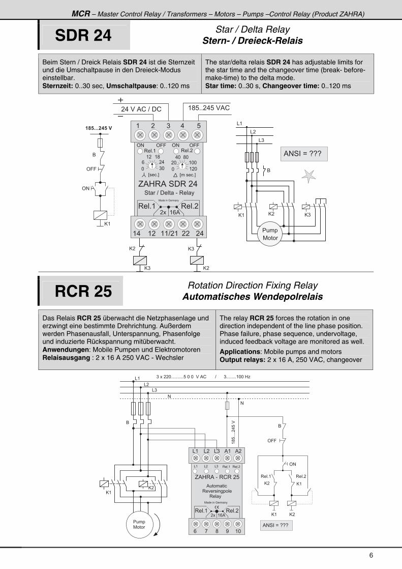
SDR 24 Star / Delta Relay Stern- / Dreieck-Relais
Beim Stern / Dreick Relais SDR 24 ist die Sternzeit und die Umschaltpause in den Dreieck-Modus einstellbar. Sternzeit: 0..30 sec, Umschaltpause: 0..120 ms
The star/delta relais SDR 24 has adjustable limits for the star time and the changeover time (break- before-make-time) to the delta mode. Star time: 0..30 s, Changeover time: 0..120 ms
@ ) @ �
@ �
( ; 8 + + � . 8 � $ % !� . � $ � % ! � ? � � ! �
@ ( @ )
6
& (
& �
& )
� � � �
@ �
� � + + + � � � � �
' 9 9
6
' #
@ (
� E � � � + F � E � � � � � + F
4 � � ? � � � � � � - � 3 � � �
( � ) . 8
G % 0 3 % � 4 � 3 � � . � �
' # ' # ' 9 9' 9 9
3 � � + ( 3 � � + �
@ )
* ) *
/ � .
( � ( ;
* ( � *
� * ( * *
. * ; *
( . ( � ( ( ? � ( � � � .
3 � � + ( 3 � � + �
7 � � � � � � : � � � �
� � � � ( / %
7 � � �
% # 4 � � B � 5 5 5 �
RCR 25 Rotation Direction Fixing Relay Automatisches Wendepolrelais
Das Relais RCR 25 überwacht die Netzphasenlage und erzwingt eine bestimmte Drehrichtung. Außerdem werden Phasenausfall, Unterspannung, Phasenfolge und induzierte Rückspannung mitüberwacht. Anwendungen: Mobile Pumpen und Elektromotoren Relaisausgang : 2 x 16 A 250 VAC - Wechsler
The relay RCR 25 forces the rotation in one direction independent of the line phase position. Phase failure, phase sequence, undervoltage, induced feedback voltage are monitored as well.
Applications: Mobile pumps and motors Output relays: 2 x 16 A, 250 VAC, changeover
& (
& �
& )
#
' 9 9
6
' #
) � � � � � * + + + + + + + + + + 8 � * � * � � $ � % ! � � � � � � � ? � � � � � � ) + + + + + + + + ( * * � 0 1
@ (
3 � � + �
G % 0 3 % � - � 3 ! 3 � � 8
& ( & ) % (& � % �
& (
/ ; < ( *,
7 � � � � � � : � � � �
& � & ) 3 � � + (
#
6
% � � � � � � �
3 � � � � � � � � � �
@ �
@ ( @ �
3 � � + ( 3 � � + �
@ (@ �
(;8++++�.8�$
3 � � + ( 3 � � + �
� � � � ( / %
3 � � �
� � � �
7 � � � % # 4 � � B � 5 5 5 �
6
MCR – Master Control Relay / Transformers – Motors – Pumps –Protection Relay
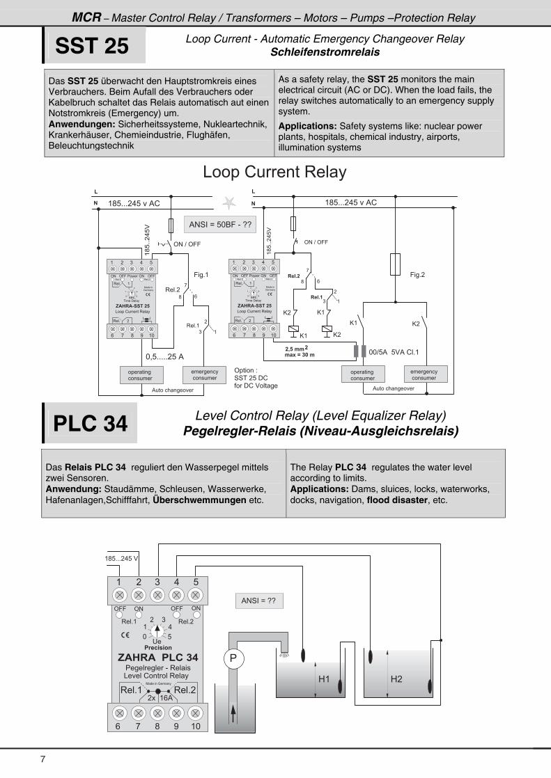
SST 25 Loop Current - Automatic Emergency Changeover Relay Schleifenstromrelais
Das SST 25 überwacht den Hauptstromkreis eines Verbrauchers. Beim Aufall des Verbrauchers oder Kabelbruch schaltet das Relais automatisch aut einen Notstromkreis (Emergency) um. Anwendungen: Sicherheitssysteme, Nukleartechnik, Krankerhäuser, Chemieindustrie, Flughäfen, Beleuchtungstechnik
As a safety relay, the SST 25 monitors the main electrical circuit (AC or DC). When the load fails, the relay switches automatically to an emergency supply system.
Applications: Safety systems like: nuclear power plants, hospitals, chemical industry, airports, illumination systems
@ (@ �
@ (
(;8++�.8$�
' # � ? � ' 9 9
(
�
� � � + �
�
)
/
,
� � � + �
(
;
@ �
@ ( @ �
* * ? 8 % � � 8 $ % � ! � + (. � - � / � � � � .
� 0 � � . .�
' � � � � � � 2
4 4 � � � 8 � � !
� � � � ! � $ � � � � �
( ; 8 + + + � . 8 � � % !
(;8++�.8$�
' # � ? � ' 9 9
(
�
3 � � + (
�
)
/
,
% � � � � � � � � � � �
9 � � + (
3 � � + �
(
;
� � � � � � �
� � � � � � � �
* = 8 + + + + + � 8 � %
� � � � � � � �
� � � � � � � �
( ; 8 + + + � . 8 � � % !
� � � � � � � �
� � � � � � � �
% � � � � � � � � � � �
& � � � � ! � � � � � 3 � � �
9 � � + �
� � � � � � �
� � � � � � � �
% # 4 � � B � 8 * 6 9 � - � 5 5
' 9 9 � � � � ' 9 9
/ ; <, ( *
' #
7 � � � � �
: � � � �
( ) .� 8
' #
� � � +
� � � � � � � � �
, $ � � $ & � � � � � �
3 � � +
3 � � +
(
�
3 � � + ( 3 � � + �
& � � � � ! � � � � � 3 � � �
* 8
( .
� )
' 9 9 � � � � ' 9 9
/ ; <, ( *
' #
7 � � � � �
: � � � �
( ) .� 8
' #
� � � +
� � � � � � � � �
, $ � � $ & � � � � � �
3 � � +
3 � � +
(
�
3 � � + ( 3 � � + �
& � � � � ! � � � � � 3 � � �
* 8
( .
� )
PLC 34 Level Control Relay (Level Equalizer Relay) Pegelregler-Relais (Niveau-Ausgleichsrelais)
Das Relais PLC 34 reguliert den Wasserpegel mittels zwei Sensoren. Anwendung: Staudämme, Schleusen, Wasserwerke, Hafenanlagen,Schifffahrt, Überschwemmungen etc.
The Relay PLC 34 regulates the water level according to limits. Applications: Dams, sluices, locks, waterworks, docks, navigation, flood disaster, etc.
( ) .� 8
� �
3 � � + ( 3 � � + �
' #' 9 9 ' # ' 9 9
� 1 � 2 � 3 4
, $ � � $ � � � ( � � � �
� � � � � � � � � � - � 3 � � � �
& � � � � ! � � � � � � 3 � � �
/ , ; < ( *
( ; 8 + + + � . 8 � $
�
* 8
( .
� )
3 � � + ( 3 � � + �
7 � � � � � � : � � � �
� � � � ( / %
0 ( 0 �
% # 4 � � B � 5 5 �
7
MCR – Master Control Relay / Transformers – Motors – Pumps –Control Relay (Product ZAHRA)
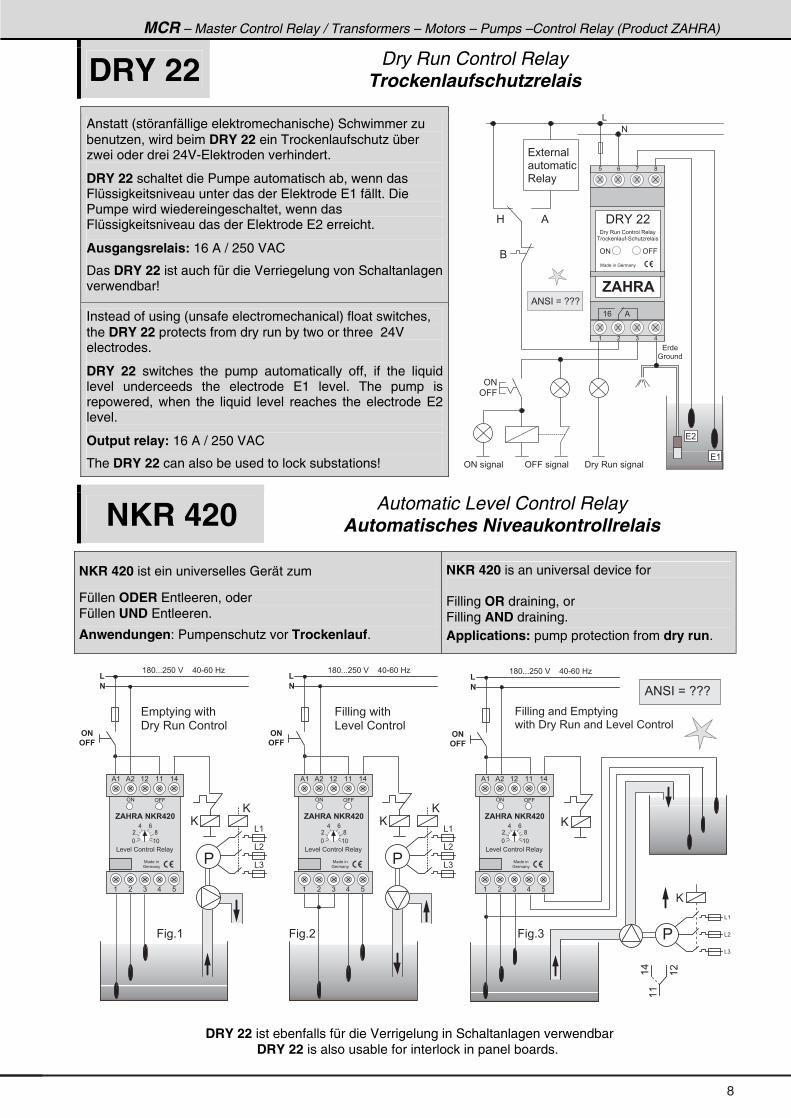
DRY 22 Dry Run Control Relay Trockenlaufschutzrelais
Anstatt (störanfällige elektromechanische) Schwimmer zu benutzen, wird beim DRY 22 ein Trockenlaufschutz über zwei oder drei 24V-Elektroden verhindert.
DRY 22 schaltet die Pumpe automatisch ab, wenn das Flüssigkeitsniveau unter das der Elektrode E1 fällt. Die Pumpe wird wiedereingeschaltet, wenn das Flüssigkeitsniveau das der Elektrode E2 erreicht.
Ausgangsrelais: 16 A / 250 VAC
Das DRY 22 ist auch für die Verriegelung von Schaltanlagen verwendbar!
Instead of using (unsafe electromechanical) float switches, the DRY 22 protects from dry run by two or three 24V electrodes.
DRY 22 switches the pump automatically off, if the liquid level underceeds the electrode E1 level. The pump is repowered, when the liquid level reaches the electrode E2 level.
Output relay: 16 A / 250 VAC
The DRY 22 can also be used to lock substations!
� �
� (
&
#
� � �
: � � � �
� � � � � �
� � � � � � �
3 � � �
6
0 %
' # � � � � � � ' 9 9 � � � � � � � � � 3 � � � � � � � �
� � , $ � � $
� 3 K � � �
' # ' 9 9
� � � 3 � � � ! � � � � � � 3 � � �
� � � � � � � � - 4 � � � � 1 � � � �
7 � � � � � � : � � � �
8 / , ;
( / %
( � ) .
' #
' 9 9
% # 4 � � B � 5 5 5
NKR 420 Automatic Level Control Relay Automatisches Niveaukontrollrelais
NKR 420 ist ein universelles Gerät zum
Füllen ODER Entleeren, oder Füllen UND Entleeren.
Anwendungen: Pumpenschutz vor Trockenlauf.
NKR 420 is an universal device for Filling OR draining, or Filling AND draining. Applications: pump protection from dry run.
(
�
( ; * + + + � 8 * � $ � � � � . * - / * � 0 1
� � � � � � � � � � � � � �
� � � 3 � � � ! � � � � �
@
@& (
& �
& )
9 � � � � � � � � � � � � � � � � � �
� � � � � � � � 3 � � � � � � & � � � � ! � � � � �
&
&
&
(
�
)
# �
# � �
(
�
( ; * + + + � 8 * � $ � � � � . * - / * � 0 1
@
# �
# � �
@
(
�
( ; * + + + � 8 * � $ � � � � . * - / * � 0 1
9 � � � � � � � � � � � �
& � � � � ! � � � � �
@
@& (
& �
& )
# �
# � �
�
((
(.
(�
9 � � + ( 9 � � + � 9 � � + )
' # ' 9 9
, $ � � $ � � * � � � �
7 � � � � �
: � � � �
& � � � � ! � � � � � � 3 � � �
% ( ( � ( (% � ( .
( ) .� 8
* ( *
� ;
. /
' # ' 9 9
, $ � � $ � � * � � � �
7 � � � � �
: � � � �
& � � � � ! � � � � � � 3 � � �
% ( ( � ( (% � ( .
( ) .� 8
* ( *
� ;
. /
' # ' 9 9
, $ � � $ � � * � � � �
7 � � � � �
: � � � �
& � � � � ! � � � � � � 3 � � �
% ( ( � ( (% � ( .
( ) .� 8
* ( *
� ;
. /
�
�
% # 4 � � B � 5 5 5 �
DRY 22 ist ebenfalls für die Verrigelung in Schaltanlagen verwendbar DRY 22 is also usable for interlock in panel boards.
8
MCR – Master Control Relay / Transformers – Motors – Pumps –Protection Relay
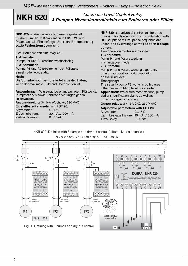
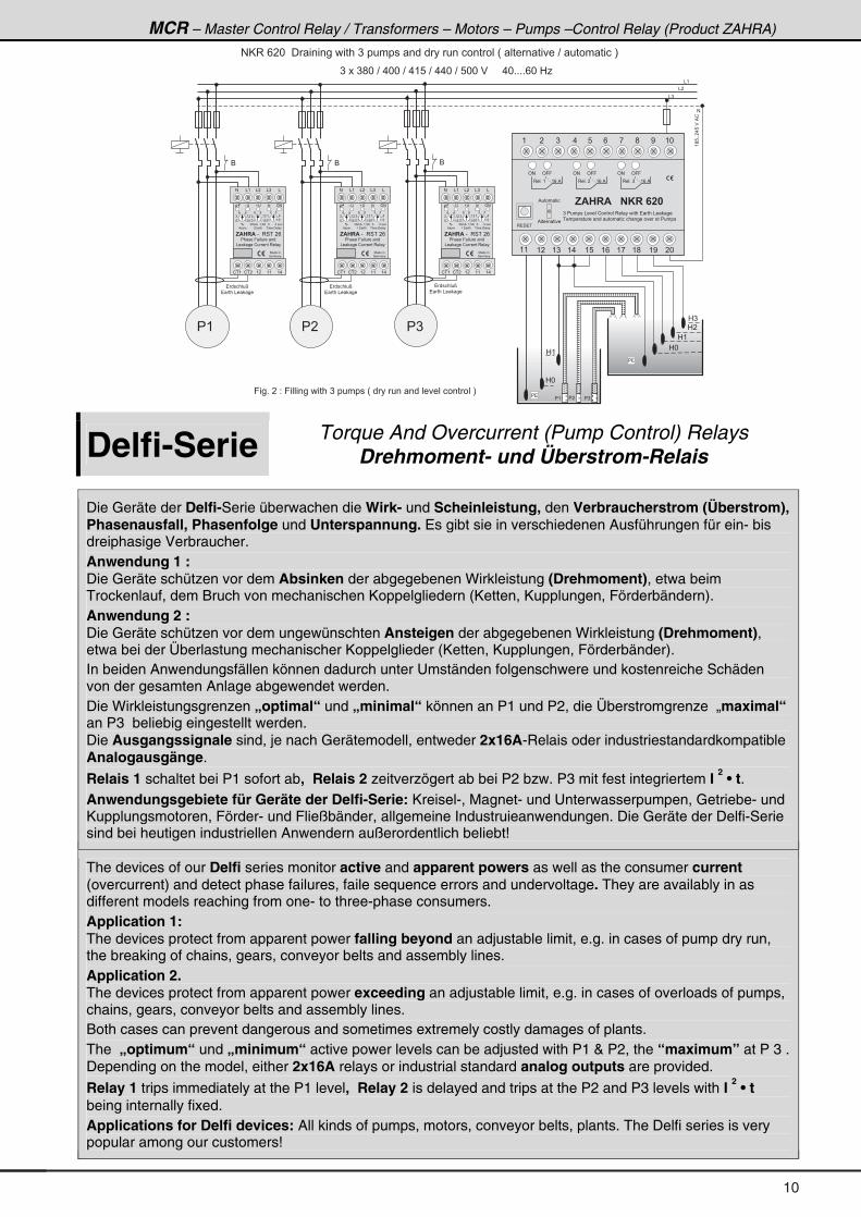
NKR 620 Automatic Level Control Relay 3-Pumpen-Niveaukontrollrelais zum Entleeren oder Füllen
NKR 620 ist eine universelle Steuerungseinheit für drei Pumpen. In Kombination mit RST 26 wird Phasenausfall, Phasenfolge, Unter- und Überspannung sowie Fehlerstrom überwacht. Zwei Betriebsarten sind möglich: 1. Alternativ Pumpe P1 und P2 arbeiten wechselseitig. 2. Automatisch Pumpe P1 und P2 arbeiten je nach Füllstand einzeln oder kooperativ. Notfall: Die Sicherheitspumpe P3 arbeitet in beiden Fällen, wenn der maximale Füllstand überschritten ist. Anwendungen: Wasseraufbereitungsanlagen, Klärwerke, Pumpstationen sowie Schutzeinrichtungen gegen Hochwasser. Ausgangsrelais: 3x 16A Wechsler, 250 VAC Einstellbare Parameter mit RST 26: Asymmetrie: 0...15% Erdschlußstrom: 30 mA...1500 mA Zeitverzögerung: 0...5 Sek.
NKR 620 is a universal control unit for three pumps. This device monitors in combination with RST 26 phase failure, phase sequence and under- and overvoltage as well as earth leakage current. Two operation modes are provided: 1. Alternative Pump P1 and P2 are working in changeover mode. 2. Automatic Pump P1 and P2 are working separately or in a coorperative mode depending on the filling level. Emergency: The security pump P3 works in both cases if the maximum filling level is exceeded. Application: Water treatment stations, pump stations, purification plants as well as protection against flooding. Output relays: 3 x 16A C/O, 250 V /AC Adjustable parameters with RST 26: Asymmetry: 0...15% Earth Leakage Failure: 30 mA...1500 mA Time Delay: 0...5 sec.
# @ 3 � / � * � � � � � � � � � � � � � � ) � � � � � � � � � � � � � � � � � � � � � � � H � � � � � � � � � ? � � � � � � � � � I
� (
6
� � � � � � � D
� � � � & � � �
& (
& �
& )
(;8++�.8�$�%!
C � � � 1 � � � � D
� � � � � � � � � �
�(
��
�)
0 *
0 (
0 �
0 )
� �9 � � + � ( � � � � � � � � � � � � ) � � � � � � � � � � � � � � � � � � � � � �
) � � � ) ; * � ? � . * * � ? � . ( 8 � ? � . . * � ? � 8 * * � $ � � � � � . * + + + + / * � 0 1
6
� � � � � � � D
� � � � & � � �
6
� � � � � � � D
� � � � & � � �
� � � )
' #
3 � 4 � �
, $ � � $ � � � � * � � � �
' 9 9
3 � � + � ( ( / � %
' # ' 9 9
3 � � + � � ( / � %
' # ' 9 9
3 � � + � ) ( / � %
) � � � � � � � & � � � � ! � � � � � � 3 � � � � � � � � � � � � � & � � �
� � � � � � � � � � � � � � � � � � � � � � � � � � � � � � � � � � � � �% � � � � � � �
% � � � � � � �
( � ) . 8 / , ; < ( *
( ( ( � ( ) ( . ( 8 ( / ( , ( ; ( < � *
% # 4 � � B � 5 5 5 �
5 ) * � % ( = 8 % * 8 � � � �
� � � � � ' #-
& � � � � ! � � � � � 3 � � �
, $ � � $ � - � � 3 4 � � � /
7 � � � � �
: � � � �
% � � � + � � � � � � � � � � � � � �
� � � � � 9 � � � � � � �
# & � & )& ( &
! � ( ( �! � � ( .( (
( 8
) ( �
/ <
* ( 8
) ( �
/ ;
* 8
( .
� )
*
5 ) * � % ( = 8 % * 8 � � � �
� � � � � ' #-
& � � � � ! � � � � � 3 � � �
, $ � � $ � - � � 3 4 � � � /
7 � � � � �
: � � � �
% � � � + � � � � � � � � � � � � � �
� � � � � 9 � � � � � � �
# & � & )& ( &
! � ( ( �! � � ( .( (
( 8
) ( �
/ <
* ( 8
) ( �
/ ;
* 8
( .
� )
*
5 ) * � % ( = 8 % * 8 � � � �
� � � � � ' #-
& � � � � ! � � � � � 3 � � �
, $ � � $ � - � � 3 4 � � � /
7 � � � � �
: � � � �
% � � � + � � � � � � � � � � � � � �
� � � � � 9 � � � � � � �
# & � & )& ( &
! � ( ( �! � � ( .( (
( 8
) ( �
/ <
* ( 8
) ( �
/ ;
* 8
( .
� )
*
9
MCR – Master Control Relay / Transformers – Motors – Pumps –Control Relay (Product ZAHRA)
� �
0 *
0 (
� �
0 *
0 (
0 �
0 )
� )� �� (
& (
& �
& )
#
(;8++�.8�$�%!
9 � � + � � � 2 � 9 � � � � � � � � � � � � ) � � � � � � � H � � � � � � � � � � � � � � � � � � � � � � I
) � � � ) ; * � ? � . * * � ? � . ( 8 � ? � . . * � ? � 8 * * � $ � � � � � . * + + + + / * � 0 1
6
� � � � � � � D
� � � � & � � �
6
� � � � � � � D
� � � � & � � �
6
� � � � � � � D
� � � � & � � �
# @ 3 � / � * � � � � � � � � � � � � � � ) � � � � � � � � � � � � � � � � � � � � � � � H � � � � � � � � � ? � � � � � � � � � I
� ( � � � )
' #
3 � 4 � �
, $ � � $ � � � � * � � � �
' 9 9
3 � � + � ( ( / � %
' # ' 9 9
3 � � + � � ( / � %
' # ' 9 9
3 � � + � ) ( / � %
) � � � � � � � & � � � � ! � � � � � � 3 � � � � � � � � � � � � � & � � �
� � � � � � � � � � � � � � � � � � � � � � � � � � � � � � � � � � � � �% � � � � � � �
% � � � � � � �
( � ) . 8 / , ; < ( *
( ( ( � ( ) ( . ( 8 ( / ( , ( ; ( < � *
( 8
) ( �
/ <
* ( 8
) ( �
/ ;
* 8
( .
� )
*
5 ) * � % ( = 8 % * 8 � � � �
� � � � � ' #-
& � � � � ! � � � � � 3 � � �
, $ � � $ � - � � 3 4 � � � /
7 � � � � �
: � � � �
% � � � + � � � � � � � � � � � � � �
� � � � � 9 � � � � � � �
# & � & )& ( &
! � ( ( �! � � ( .( (
( 8
) ( �
/ <
* ( 8
) ( �
/ ;
* 8
( .
� )
* ( 8
) ( �
/ <
* ( 8
) ( �
/ ;
* 8
( .
� )
*
5 ) * � % ( = 8 % * 8 � � � �
� � � � � ' #-
& � � � � ! � � � � � 3 � � �
, $ � � $ � - � � 3 4 � � � /
7 � � � � �
: � � � �
% � � � + � � � � � � � � � � � � � �
� � � � � 9 � � � � � � �
# & � & )& ( &
! � ( ( �! � � ( .( (
( 8
) ( �
/ <
* ( 8
) ( �
/ ;
* 8
( .
� )
*
Delfi-Serie Torque And Overcurrent (Pump Control) Relays Drehmoment- und Überstrom-Relais
Die Geräte der Delfi-Serie überwachen die Wirk- und Scheinleistung, den Verbraucherstrom (Überstrom), Phasenausfall, Phasenfolge und Unterspannung. Es gibt sie in verschiedenen Ausführungen für ein- bis dreiphasige Verbraucher. Anwendung 1 : Die Geräte schützen vor dem Absinken der abgegebenen Wirkleistung (Drehmoment), etwa beim Trockenlauf, dem Bruch von mechanischen Koppelgliedern (Ketten, Kupplungen, Förderbändern). Anwendung 2 : Die Geräte schützen vor dem ungewünschten Ansteigen der abgegebenen Wirkleistung (Drehmoment), etwa bei der Überlastung mechanischer Koppelglieder (Ketten, Kupplungen, Förderbänder). In beiden Anwendungsfällen können dadurch unter Umständen folgenschwere und kostenreiche Schäden von der gesamten Anlage abgewendet werden. Die Wirkleistungsgrenzen „optimal“ und „minimal“ können an P1 und P2, die Überstromgrenze „maximal“ an P3 beliebig eingestellt werden. Die Ausgangssignale sind, je nach Gerätemodell, entweder 2x16A-Relais oder industriestandardkompatible Analogausgänge.
Relais 1 schaltet bei P1 sofort ab, Relais 2 zeitverzögert ab bei P2 bzw. P3 mit fest integriertem I 2 • t.
Anwendungsgebiete für Geräte der Delfi-Serie: Kreisel-, Magnet- und Unterwasserpumpen, Getriebe- und Kupplungsmotoren, Förder- und Fließbänder, allgemeine Industruieanwendungen. Die Geräte der Delfi-Serie sind bei heutigen industriellen Anwendern außerordentlich beliebt!
The devices of our Delfi series monitor active and apparent powers as well as the consumer current (overcurrent) and detect phase failures, faile sequence errors and undervoltage. They are availably in as different models reaching from one- to three-phase consumers. Application 1: The devices protect from apparent power falling beyond an adjustable limit, e.g. in cases of pump dry run, the breaking of chains, gears, conveyor belts and assembly lines. Application 2. The devices protect from apparent power exceeding an adjustable limit, e.g. in cases of overloads of pumps, chains, gears, conveyor belts and assembly lines. Both cases can prevent dangerous and sometimes extremely costly damages of plants. The „optimum“ und „minimum“ active power levels can be adjusted with P1 & P2, the “maximum” at P 3 . Depending on the model, either 2x16A relays or industrial standard analog outputs are provided.
Relay 1 trips immediately at the P1 level, Relay 2 is delayed and trips at the P2 and P3 levels with I 2 • t
being internally fixed. Applications for Delfi devices: All kinds of pumps, motors, conveyor belts, plants. The Delfi series is very popular among our customers!
10
MCR – Master Control Relay / Transformers – Motors – Pumps –Protection Relay
Delfi 22 Delfi 44
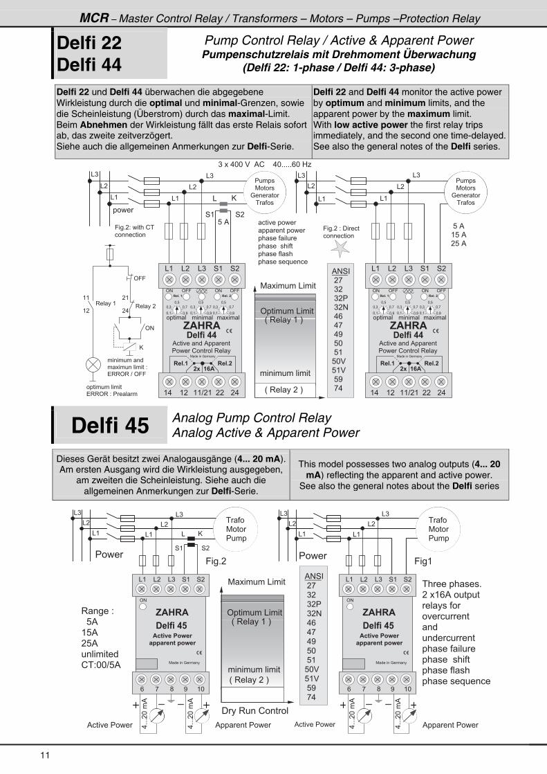
Pump Control Relay / Active & Apparent Power Pumpenschutzrelais mit Drehmoment Überwachung
(Delfi 22: 1-phase / Delfi 44: 3-phase)
Delfi 22 und Delfi 44 überwachen die abgegebene Wirkleistung durch die optimal und minimal-Grenzen, sowie die Scheinleistung (Überstrom) durch das maximal-Limit. Beim Abnehmen der Wirkleistung fällt das erste Relais sofort ab, das zweite zeitverzögert. Siehe auch die allgemeinen Anmerkungen zur Delfi-Serie.
Delfi 22 and Delfi 44 monitor the active power by optimum and minimum limits, and the apparent power by the maximum limit. With low active power the first relay trips immediately, and the second one time-delayed.See also the general notes of the Delfi series.
� � � � � � � � �
� � � � � � � � � �
� � � � � � � � � �
� � � � � � � � � � �
� � � � � � � � �
� � � � � � � � � � � � �
& @
& )
& �
& (
4 ( 4 �
& )
& �
& (
9 � � + � 2 � � � � � � ! �
� � � � � � � � � �
& )& )
& (
& �
& (
& �
' � � � � � � � & � � � �
7 � � � � � � & � � � �
� � � �
� � � � � � � � � � � � �
H � 3 � � � � ( � I
� � � � �
7 � � � �
: � � � � �
� � � �
� ) � � � . * * � $ � � % ! � � � � . * + + + + + / * � 0 1
9 � � + � � 2 � � � � � �
� � � � � � � � � �
� � � � � � � � � � � � �
� 3 3 ' 3 � 2 � � � � �
� � � � � � � � � �
� � � � � � � � � � � � � 2
� 3 3 ' 3 � ? � ' 9 9
8 � %� 8 � %
( 8 � % �
� 8 � %
3 � � � � �
� (
� .
' 9 9
' #
( (
( �
3 � � � � (
@
% # 4 �
� � , �
� ) �
� ) � �
� ) � #
� . /
� . ,
� . <
� 8 *
� 8 (
8 * $
8 ( $
� 8 <
� , . �
' # ' 9 9 ' 9 9' #
& ( & � & ) 4 ( 4 �
� � � � � � � � � � � �
, $ � � $
% � � � � � � � � % � � � � �
� � � � � ! � � � � � � 3 � � �
� � � � � � �
( . ( � ( ( ? � ( � � � .
* = )
* = 8
* = ,
* = <* = (
* = )
* = 8
* = ,
* = <* = (
* = )
* = 8
* = ,
* = <* = (
� � � + �
7 � � � � � � : � � � �
� - � � � $
� � � + �
� � � � �
� � � + � �� � � + � �
� � � � �
7 � � � �
: � � � � �
� � � �
H � 3 � � � � � � I
Delfi 45 Analog Pump Control Relay Analog Active & Apparent Power
Dieses Gerät besitzt zwei Analogausgänge (4... 20 mA).Am ersten Ausgang wird die Wirkleistung ausgegeben,
am zweiten die Scheinleistung. Siehe auch die allgemeinen Anmerkungen zur Delfi-Serie.
This model possesses two analog outputs (4... 20 mA) reflecting the apparent and active power.
See also the general notes about the Delfi series
.+++�*��%
& @
& )
& �
& (
� � � �
4 ( 4 �
& )
& �
& (
� � � � 9 � � + �
& )
� � � 3 � � � ! � � � � �
.+++�*��%
% � � � � � � � � � % � � � � � � � � � � .+++�*��%
.+++�*��%
& �
& (
& )
& �
& (
% � � � � � � � � � % � � � � � � � � � �
' #
& ( & � & ) 4 ( 4 �
, $ � � $
� � � � � � �
/ , ; < ( *
7 � � � � � � : � � � �
$ 2 6 9 � � � 3 : � 1
� � � � 1 � 4 6 � � 3 : � 1
9 � � (
� � �
7 � � �
� � � �
� � �
7 � � �
� � � �
� � � � � � � � � � +
� � � ( / % � � � � � � � �
� � � � � � �
� � � � � � �
� � �
� � � � � � � � �
� � � � � � � � � �
� � � � � � � � � � �
� � � � � � � � �
� � � � � � � � � � � � �
3 � � � � 2 �
� � 8 %
( 8 %
� 8 %
� � � � � � � � �
! � 2 * * ? 8 %
' #
& ( & � & ) 4 ( 4 �
, $ � � $
� � � � � � �
/ , ; < ( *
7 � � � � � � : � � � �
$ 2 6 9 � � � 3 : � 1
� � � � 1 � 4 6 � � 3 : � 1
' � � � � � � � & � � � �
H � 3 � � � � � � I
� � � � � � � � � � � � �
H � 3 � � � � ( � I
7 � � � � � � & � � � �
% # 4 �
� � , �
� ) �
� ) � �
� ) � #
� . /
� . ,
� . <
� 8 *
� 8 (
8 * $
8 ( $
� 8 <
� , . �
11
� � � � � � � � �
� � � � � � � � � �
� � � � � � � � � �
� � � � � � � � � � �
� � � � � � � � �
� � � � � � � � � � � � �
& @
& )
& �
& (
4 ( 4 �
& )
& �
& (
& )& )
& (
& �
& (
& �
� � � �
� � � � �
7 � � � �
: � � � � �
� � � �
� ) � � � . * * � $ � � % ! � � � � . * + + + + + / * � 0 1
� � � � �
7 � � � �
: � � � � �
� � � �
� � � � � � � � � � � �
� 3 3 ' 3 � 2 � � � � �
� � � � � � � � � �
� � � � � � � � � � � � � 2
� 3 3 ' 3 � ? � ' 9 9
8 � %
8 � %
( 8 � % �
� 8 � %
3 � � � � �
� (
� .
' 9 9
' #
( (
( �
3 � � � � (
@
' # ' 9 9 ' 9 9' #
& ( & � & ) 4 ( 4 �
� � � � � � � � � � � �
, $ � � $
% � � � � � � � � % � � � � �
� � � � � ! � � � � � � 3 � � �
� � � � �
( . ( � ( ( ? � ( � � � .
� � � + � �� � � + � �
* = )
* = 8
* = ,
* = <* = (
* = )
* = 8
* = ,
* = <* = (
* = )
* = 8
* = ,
* = <* = (
� � � + �
7 � � � � � � : � � � �
� - � � � $
� � � + �
� � � � �
' # ' 9 9 ' 9 9' #
& ( & � & ) 4 ( 4 �
� � � � � � � � � � � �
, $ � � $
% � � � � � � � � % � � � � �
� � � � � ! � � � � � � 3 � � �
� � � � �
( . ( � ( ( ? � ( � � � .
* = )
* = 8
* = ,
* = <* = (
* = )
* = 8
* = ,
* = <* = (
* = )
* = 8
* = ,
* = <* = (
� � � + �
7 � � � � � � : � � � �
� - � � � $
� � � + �
� � � � �
' � � � � � � � & � � � �
7 � � � � � � & � � � �
� � � � � � � � � � � � �
H � 3 � � � � ( � I
9 � � + � 2 � � � � � � ! �
� � � � � � � � � �
9 � � + � � 2 � � � � � �
� � � � � � � � � �
� � � + � �� � � + � �
% # 4 �
� � , �
� ) �
� ) � �
� ) � #
� . /
� . ,
� . <
� 8 *
� 8 (
8 * $
8 ( $
� 8 <
� , . �
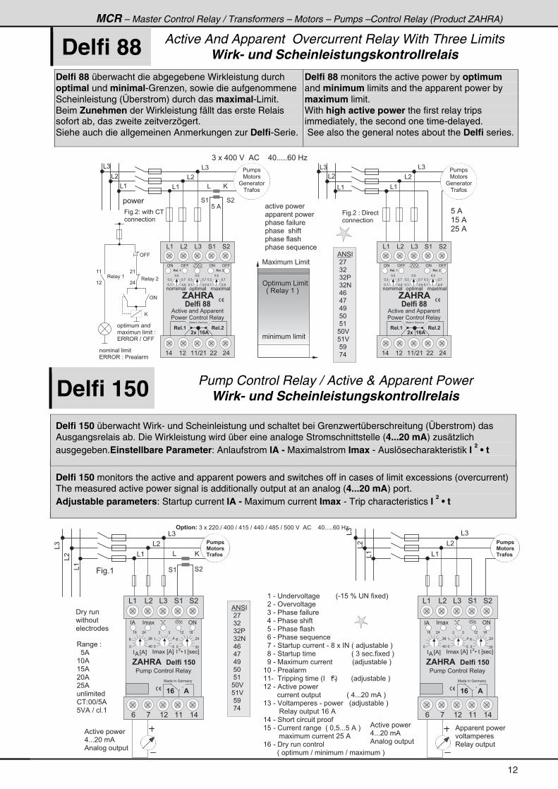
Delfi 150 Pump Control Relay / Active & Apparent Power Wirk- und Scheinleistungskontrollrelais
Delfi 150 überwacht Wirk- und Scheinleistung und schaltet bei Grenzwertüberschreitung (Überstrom) das Ausgangsrelais ab. Die Wirkleistung wird über eine analoge Stromschnittstelle (4...20 mA) zusätzlich ausgegeben.Einstellbare Parameter: Anlaufstrom IA - Maximalstrom Imax - Auslösecharakteristik I
2 • t
Delfi 150 monitors the active and apparent powers and switches off in cases of limit excessions (overcurrent) The measured active power signal is additionally output at an analog (4...20 mA) port. Adjustable parameters: Startup current IA - Maximum current Imax - Trip characteristics I
2 • t
& @
& )
& �
& (
4 ( 4 �
& )
& �
& (
9 � � + (
&(
&�
&)
&(
&�
&)
' #
, $ � � $ � � � � � � � � � �
7 � � � � � � : � � � �
� � � � � ! � � � � � � 3 � � �
& ( & ) 4 (& � 4 �
/ ( � ( ( ( .,
� � � � E % F%
* . *
; ) /
( / � .
� � � � E % F
* 8
( .
� )
* ) *
/ � .
( � ( ;
� � � L � � � E � � � F�
� � �� %
� � $
� � ( � - � � � � � � � � � � � � � � � � � � H - ( 8 � J � � # � � � � � � I
� � � � - � ' � � � � � �
� � ) � - � � � � � � � � � � �
� � . � - � � � � � � � � � � �
� � 8 � - � � � � � � � � � �
� � / � - � � � � � � � � � � � � � �
� � , � - � 4 � � � � � � � � � � � - � ; � � � � # � H � � > � � � " � � � I
� � ; � - � 4 � � � � � � � � � � � � � � � � � � � � � � � � � � � H � ) � � � � + � � � � � � I
� � < � - � 7 � � � � � � � � � � � � � � � � � � � � � H � > � � � " � � � I
( * � - � � � � �
( ( - � � � � � � � � � � � � � � � H � � � � � � I � � � � � � � H � > � � � " � � � I
( � � - � % � � � � � � � � � �
� � � � � � � � � � � � � � � � � � � � � � � � � � � � � � � � H � . + + + � * � � % � I
( ) � - � $ � � � � � � � � � - � � � � � � � � H � > � � � " � � � I
� � � � � � � � 3 � � � � � � � � � � � ( / � %
( . � - � 4 � � � � � � � � � � � � � � �
( 8 � - � ! � � � � � � � � � � H � * = 8 + + + 8 � % � I
� � � � � � � � � � � � � � � � � � � � � � 8 � %
( / � - � � � � � � � � � � � � �
� � � � � � � H � � � � � � � � � ? � � � � � � � � � ? � � � � � � � � I
�
�
% � � � � � � � � �
. + + + � * � � %
% � � � � � � � � � � �
# � 6 3 4 7 � ) � � � � � * + ? � . * * � ? � . ( 8 � ? � . . * � ? � . ; 8 � ? � 8 * * � $ � � % ! � � � � . * + + + + + / * � 0 1
3 � � � � 2 �
� � 8 %
( * %
( 8 %
� * %
� 8 %
� � � � � � � � �
! � 2 * * ? 8 %
8 $ % � ? � � � + (
� 8 . � �
% 3 6 3 1 �
� 1 � � 3 �
� 8 . � �
% 3 6 3 1 �
� 1 � � 3 �
% � � � � � � � � �
. + + + � * � � %
% � � � � � � � � � � �
% � � � � � � � � � �
� � � � � � � �
3 � � � � � � � � � �
� � � � �
� � � � � � �
� � � � � � � � � �
' #
, $ � � $ � � � � � � � � � �
7 � � � � � � : � � � �
� � � � � ! � � � � � � 3 � � �
& ( & ) 4 (& � 4 �
/ ( � ( ( ( .,
� � � � E % F%
* . *
) /
( / � .
� � � � E % F
* 8
( .
� )
* ) *
/ � .
( � ( ;
� � � L � � � E � � � F�
� � �� %
� � $
% # 4 �
� � , �
� ) �
� ) � �
� ) � #
� . /
� . ,
� . <
� 8 *
� 8 (
8 * $
8 ( $
� 8 <
� , . �
MCR – Master Control Relay / Transformers – Motors – Pumps –Control Relay (Product ZAHRA)
Delfi 88 Active And Apparent Overcurrent Relay With Three Limits Wirk- und Scheinleistungskontrollrelais
Delfi 88 überwacht die abgegebene Wirkleistung durch optimal und minimal-Grenzen, sowie die aufgenommene Scheinleistung (Überstrom) durch das maximal-Limit. Beim Zunehmen der Wirkleistung fällt das erste Relais sofort ab, das zweite zeitverzögert. Siehe auch die allgemeinen Anmerkungen zur Delfi-Serie.
Delfi 88 monitors the active power by optimum and minimum limits and the apparent power by maximum limit. With high active power the first relay trips immediately, the second one time-delayed. See also the general notes about the Delfi series.
12
MCR – Master Control Relay / Transformers – Motors – Pumps –Protection Relay
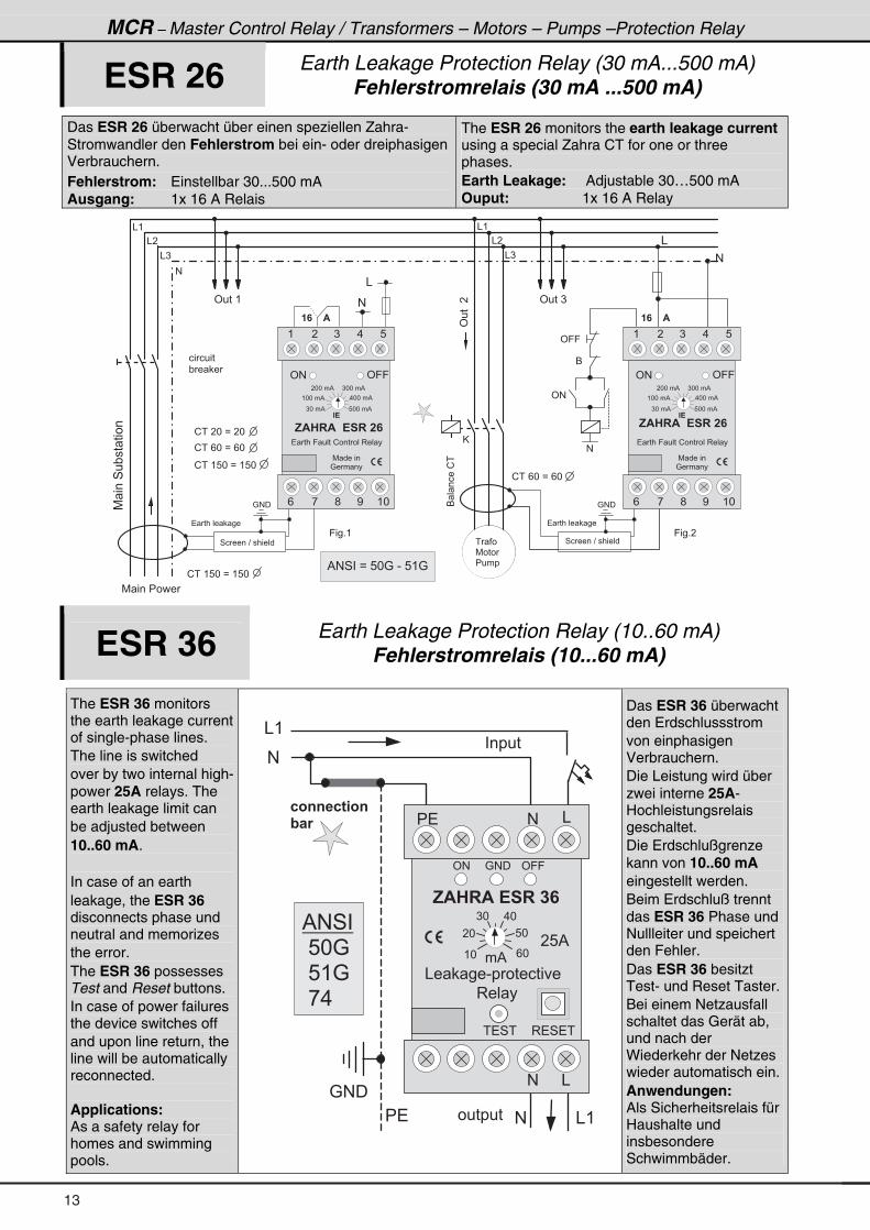
ESR 26 Earth Leakage Protection Relay (30 mA...500 mA) Fehlerstromrelais (30 mA ...500 mA)
Das ESR 26 überwacht über einen speziellen Zahra-Stromwandler den Fehlerstrom bei ein- oder dreiphasigen Verbrauchern. Fehlerstrom: Einstellbar 30...500 mA Ausgang: 1x 16 A Relais
The ESR 26 monitors the earth leakage current using a special Zahra CT for one or three phases. Earth Leakage: Adjustable 30…500 mA Ouput: 1x 16 A Relay
� 7 � � � � � � �
& (
& �
& )
#
7 ���4�"�� ����
! � � � * � B � � *
! � � / * � B � / *
! � � ( 8 * � B � ( 8 *
6 � ����!�
#
� � � � � $
� � � � � � � �
9 � � + (
' � � � (
&
4 � � � � � ? � � � � � � �
: # �
� � � � � �
" � �
! � � ( 8 * � B � ( 8 *
& (
& �
& )#
� � � � � � � �
9 � � + �
' � � � )
&
4 � � � � � ? � � � � � � �
: # �
! � � / * � B � / *
' 9 9
6
' #
@
� � � � � $
#
'�����
� � �
7 � � �
� � � �% # 4 � � B � 8 * : � - � 8 ( : �
/ <;, ( *
( ) .� 8
' 9 9' #
7 � � � � �
: � � � �
, $ � � $ � � ! � � � �
� � � � 9 � � � � ! � � � � � � 3 � � �
) * � � % 8 * * � � %
( * * � � %
� * * � � % ) * * � � %
. * * � � %
" !
/ <;, ( *
( ) .� 8
' 9 9' #
7 � � � � �
: � � � �
, $ � � $ � � ! � � � �
� � � � 9 � � � � ! � � � � � � 3 � � �
) * � � % 8 * * � � %
( * * � � %
� * * � � % ) * * � � %
. * * � � %
" !
ESR 36 Earth Leakage Protection Relay (10..60 mA) Fehlerstromrelais (10...60 mA)
The ESR 36 monitors the earth leakage current of single-phase lines. The line is switched over by two internal high-power 25A relays. The earth leakage limit can be adjusted between 10..60 mA. In case of an earth leakage, the ESR 36 disconnects phase und neutral and memorizes the error. The ESR 36 possesses Test and Reset buttons. In case of power failures the device switches off and upon line return, the line will be automatically reconnected. Applications: As a safety relay for homes and swimming pools.
& (
� � � � �
� � � � � �
#
� �
: # �
& (#
2 3 4 4 � 2 6 3 4
@ � 1� � &
' 9 9
� %
8 *
. *) *
� *
( * / *
& � � � - � � � � � � � � �
' #
3 � � �
3 � 4 � �� � 4 �
#
&#
� 8 %
, $ � � $ � ! � � � �
: # �
% # 4 �
� 8 * :
� 8 ( :
� , . �
Das ESR 36 überwacht den Erdschlussstrom von einphasigen Verbrauchern. Die Leistung wird über zwei interne 25A-Hochleistungsrelais geschaltet. Die Erdschlußgrenze kann von 10..60 mA eingestellt werden. Beim Erdschluß trennt das ESR 36 Phase und Nullleiter und speichert den Fehler. Das ESR 36 besitzt Test- und Reset Taster. Bei einem Netzausfall schaltet das Gerät ab, und nach der Wiederkehr der Netzes wieder automatisch ein. Anwendungen: Als Sicherheitsrelais für Haushalte und insbesondere Schwimmbäder.
13
MCR – Master Control Relay / Transformers – Motors – Pumps –Control Relay (Product ZAHRA)
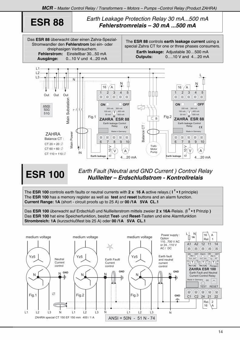
ESR 88 Earth Leakage Protection Relay 30 mA...500 mA Fehlerstromrelais – 30 mA ...500 mA
Das ESR 88 überwacht über einen Zahra-Spezial-Stromwandler den Fehlerstrom bei ein- oder
dreiphasigen Verbrauchern. Fehlerstrom: Einstellbar 30...50 mA Ausgänge: 0...10 V und 4...20 mA
The ESR 88 controls earth leakage current using a special Zahra CT for one or three phases consumers.
Earth leakage: Adjustable 30…500 mA Outputs: 0….10 V and 4…20 mA
�7 �������
& (
& �
& )
#
' � � ' � �
� #
7 ���4�"�� ����
6 � � � � � ! � � 2
! � � � * � B � � *
! � � / * � B � / *
! � � ( ( * � B � ( ( *
! � 1 6 ; � � � � < � = �
#
( / � � � � � %
&
6 � ����!��2
#
( / � � � � � %
! � 1 6 ; � � � � < � = �
9 � � + (
' � �
%
*+++(*�$
. + + + + � * � � %
%$
G % 0 3 %
$
. + + + + � * � � %
*+++(*�$
/ <;, ( *
( ) .� 8
# � �# �
7 � � � � � � : � � � �
, $ � � $ � � ! � � �
� � � � � � � � � ! � � � � � �
3 � � �
) * � � % 8 * * � � %
( * * � � %
� * * � � % ) * * � � %
. * * � � %
" !
� � �
7 � � �
� � � �
% # 4 � �
� 8 * : �
� 8 ( : �
9 � � + �
/ <;, ( *
( ) .� 8
# � �# �
7 � � � � � � : � � � �
, $ � � $ � � ! � � �
� � � � � � � � � ! � � � � � �
3 � � �
) * � � % 8 * * � � %
( * * � � %
� * * � � % ) * * � � %
. * * � � %
" !
6
ESR 100 Earth Fault (Neutral and GND Current ) Control Relay Nullleiter – Erdschlußstrom - Kontrollrelais
The ESR 100 controls earth faults or neutral currents with 2 x 16 A active relays.( I 2 • t principle)
The ESR 100 has a memory register as well as test and reset buttons and an alarm function. Current Range: 1A (short - circuit proofs up to 25 A) or 00 /1A 5VA CL.1
Das ESR 100 überwacht auf Erdschluß und Nullleiterstrom mittels zweier 2 x 16A-Relais. (I 2 • t Prinzip )
Das ESR 100 hat eine Speicherfunktion, besitzt Test- und Reset-Tasten und eine Alarmfunktion Strombreich: 1A (kurzschlußfest bis 25 A) oder 00 /1A 5VA CL.1
3 � 4 � �� � 4 �
, $ � � $ � ! � � � � � �
( .( (( �% �% (
� �� (� .! �! (
3 � � + � � � (
( / � � � � � %
( / � � � � � %
3 � � + � � � �
& #
#
� � � � 9 � � � � � � � # � � � �
! � � � � � ! � � � � � � 3 � � � �
7 � � � � � � : � � � � �
� � � � � � � � � � � � � 2 �
' � � � � � �
( ( * + + + , * * � $ � % !
� � � . + + + ( ( * � $
% ! � ? � � � !
� $
#
� � � � 9 � � � � �
! � � � �
� � � � � �
� � � � � � � �
� � � � � � � � �
� � � � �
� � � � � �
� � �
' # ' 9 9 ' 9 9' #
� � � + � �� � � + � �
* (
* = �
� � � + � � > $ ?
) *
/
( � ( ;
� .
*
" � � � � 6 � > � � 2 � ?� L�
* = .
* = ;
* = /
* (
* = �
� � � + � � > $ ?
* = . * = /
* = ;
% � �
� � �
#
� � �
#
# � � � � �
! � � � �
� � � � � �
� � � � � � � � � � � �
� � �
#
G % 0 3 % � � � � � � � � ! � � ( 8 * � � 9 � ( 8 * � � � � � . * * � ? � ( � %
�
% # 4 � � B � 8 * # � � - � � 8 ( � # � - � , .
#
& ( & � & )
K 1 8
& ( & � & )
9 � � + �
K 1 8
& ( & � & )
K 1 8
9 � � + )9 � � + (
# # #
� � � � � � � � � � � � � � � � � � � � � � � �
14
A
MCR – Master Control Relay / Transformers – Motors – Pumps –Protection Relay
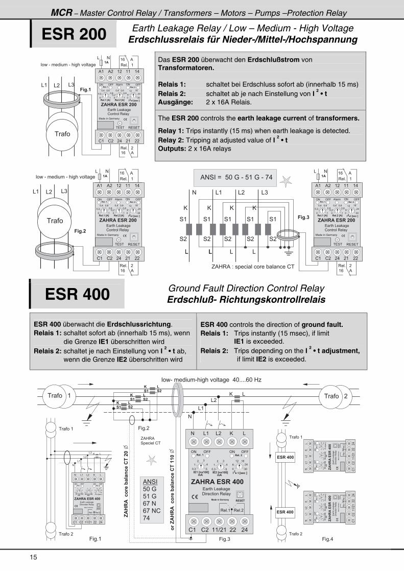
ESR 200 Earth Leakage Relay / Low – Medium - High Voltage Erdschlussrelais für Nieder-/Mittel-/Hochspannung
Das ESR 200 überwacht den Erdschlußstrom von Transformatoren. Relais 1: schaltet bei Erdschluss sofort ab (innerhalb 15 ms) Relais 2: schaltet ab je nach Einstellung von I
2 • t
Ausgänge: 2 x 16A Relais.
& � & )& (
� = + �
� � � � - � � � � � � � � - � � � � � � � � � � �
� � �
3 � 4 � �� � 4 �
, $ � � $ � ! � � � � � �
( .( (( �% �% (
� �� (� .! �! (
3 � � + � � � (
( / � � � � � %
( / � � � � � %
3 � � + � � � �
& #
� � � � & � � �
! � � � � � � 3 � � � �
7 � � � � � � : � � � � �
� $
' # ' 9 9 ' 9 9' #
� � � + � �� � � + � �
* (
* = �
� � � + � � > $ ?
) *
/
( � ( ;
� .
*
" � � � � 6 � > � � 2 � ?� L�
* = .
* = ;
* = /
* (
* = �
� � � + � � > $ ?
* = . * = /
* = ;
% � �
The ESR 200 controls the earth leakage current of transformers.
Relay 1: Trips instantly (15 ms) when earth leakage is detected. Relay 2: Tripping at adjusted value of I
2 • t
Outputs: 2 x 16A relays
� � � � - � � � � � � � � - � � � � � � � � � � �
� = + �
@
4 �
@
&
@
&
4 (
4 �
4 (
4 �
4 (
&&
& � & )& (
4 �
4 (� = + �
� � �
& � & )& (
% # 4 � � B � � 8 * � : � - � 8 ( � : � - � , .
@
&&
#
4 �
4 (
G % 0 3 % � 2 � � � � � � � � � � � � " � � � � � ! �
3 � 4 � �� � 4 �
, $ � � $ � ! � � � � � �
( .( (( �% �% (
� �� (� .! �! (
3 � � + � � � (
( / � � � � � %
( / � � � � � %
3 � � + � � � �
& #
� � � � & � � �
! � � � � � � 3 � � � �
7 � � � � � � : � � � � �
� $
' # ' 9 9 ' 9 9' #
� � � + � �� � � + � �
* (
* = �
� � � + � � > $ ?
) *
/
( � ( ;
� .
*
" � � � � 6 � > � � 2 � ?� L�
* = .
* = ;
* = /
* (
* = �
� � � + � � > $ ?
* = . * = /
* = ;
% � �
ESR 400 Ground Fault Direction Control Relay Erdschluß- Richtungskontrollrelais
ESR 400 überwacht die Erdschlussrichtung. Relais 1: schaltet sofort ab (innerhalb 15 ms), wenn
die Grenze IE1 überschritten wird Relais 2: schaltet je nach Einstellung von I
2 • t ab,
wenn die Grenze IE2 überschritten wird
ESR 400 controls the direction of ground fault. Relais 1: Trips instantly (15 msec), if limit
IE1 is exceeded. Relais 2: Trips depending on the I
2 • t adjustment,
if limit IE2 is exceeded.
@ &
& (
& �
#
� � � - � � � � � � � - � � � � � � � � � � � � . * + + + + / * � 0 1
� � � � � � (
@ &
& (
& �
#
& )
� � � � (
� � � � �
9 � � + ( 9 � � + )
� � � � (
� � � � �
! � � � � � �
9 � � + .
,$��$��231��@���42�������
! � � � � � �
� � � � � � �
G % 0 3 %
4 � � � � � � � ! �
9 � � + �
* (
� � � �
* (
� � � �
* (
� � � �
31�,$��$��231��@���42����������
% # 4 � �
8 * � :
8 ( � :
/ , � #
/ , � # !
, .
# & � @& ( &
! ( ! � ( ( ? � ( � � � .
3 � � + ( 3 � � + �
* = ) 8
(
� )
.
" ! � � > 4 - � � � ?
. $
* = ) 8
(
� )
.
* ) *
/
( � ( ;
� .
" � � � � � 6 � > � � 2 � ?� L�
" ! � � > 4 - � � � ?
. $
� ! � ! �% � B � � 4 � � � 1 . � 4 �
' # ' 9 9 ' 9 9' #
� � � + � �� � � + � �
� � � � & � � � �
� � � � � � � � � 3 � � �
, $ � � $ � ! � � � � � �
#&�
@&(
&
!(
!�
((?�(
��
�.
3��+(
3��+�
*=)
8
(
�)
.
"!��>4-���?
.$
*=)
8
(
�)
.
*)*
/
(�
(;
�.
"�����6�>��2�?
�L�
"!��>4-���?
.$
%�B�� 4���1.�4�
'#
'99
'99
'#
���+��
���+��
� ���&� ���
���������3�� �
,$��$�!������
#&�
@&(
&
!(
!�
((?�(
��
�.
3��+(
3��+�
*=)
8
(
�)
.
"!��>4-���?
.$
*=)
8
(
�)
.
*)*
/
(�
(;
�.
"�����6�>��2�?
�L�
"!��>4-���?
.$
�!�!�
%�B�� 4���1.�4�
'#
'99
'99
'#
���+��
���+��
� ���&� ���
���������3�� �
,$��$�!������
�!�!�
15
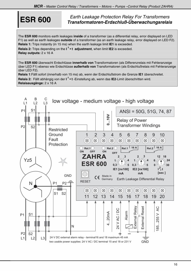
MCR – Master Control Relay / Transformers – Motors – Pumps –Control Relay (Product ZAHRA)
ESR 600 Earth Leakage Protection Relay For Transformers Transformatoren-Erdschluß-Überwachungsrelais
The ESR 600 monitors earth leakages inside of a transformer (as a differential relay, error displayed on LED F1) as well as earth leakages outside of a transformer (as an earth leakage relay, error displayed on LED F2). Relais 1: Trips instantly (in 15 ms) when the earth leakage limit IE1 is exceeded.
Relais 2: Trips depending on the I 2 • t adjustment, when limit IE2 is exceeded.
Relay outputs: 2 x 16 A
The ESR 600 überwacht Erdschlüsse innerhalb von Transformatoren (als Differenzrelais mit Fehleranzeige über LED F1) ebenso wie Erdschlüsse außerhalb von Transformatoren (als Erdschlußrelais mit Fehleranzeige über LED F2). Relais 1:Fällt sofort (innerhalb von 15 ms) ab, wenn der Erdschlußstrom die Grenze IE1 überschreitet.
Relais 2: Fällt abhängig von der I 2 • t -Einstellung ab, wenn das IE2-Limit überschritten wird.
Relaisausgänge: 2 x 16 A
(;8+++�88�$��%!
�.�$�%!�?��!
����� ��3����
: # �
� �
� (
4 �
� �
4 �
4 (
� �
� (
4 �
4 (
� (
4 (
& ( & � & )
% 6 !
3 � � � � � � � �
: � � � �
9 � � � �
� � � � � � � � �
3 � � � � � � � � � � �
� � � � � � � � C � � � � � � �
� � � � � � � � � � - � � � � � � � � � � � � � � - � � � � � � � � � � �
� . � $ � � ! � � � � � � � � � � � � � � � - � � � � � � � ( / � � � � ( ; � � � � � � � � . 8 � � %
����� ��3�� �
%� �
� � � � � � " � � � � � � � � � � � � � � � � 2 � � . � $ � % ! � ? � � ! � � � � � � � � ( 8 � � � � ( ; � � � � ) ( � $
.+++�*�%
�+++���
& ( & � & )
#
, $ � � $
� ! � � � � �
7 � � � � �
� : � � � �
3 � 4 � �
� 0 �
� �
�
" ! � � > 4 - � � � ?
�
� �
�
� �
� � �
� �
" ! � � > 4 - � � � ?
� � � + �
# � # � �
�
�
� 0 � � �
� � � � & � � � � � � � � � � � � � � � 3 � � �
� � � + �
# �
# � �
� � � + �� � � + �� � $ � � $
" � � � � 6 �
> � � 2 � ?
A
�
. $ . $
( � ) . 8 / , ; < ( *
( ( ( � ( ) ( . ( 8 ( / ( , ( ; ( < � *
% # 4 � � B � 8 * : = � 8 ( : = � , . = � ; ,
: # �
K 1 8
#
16
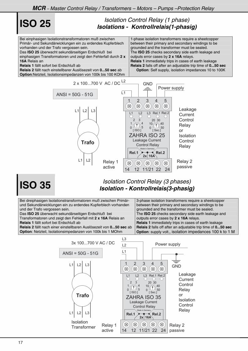
MCR – Master Control Relay / Transformers – Motors – Pumps –Protection Relay
ISO 25 Isolation Control Relay (1 phase) Isolations - Kontrollrelais(1-phasig)
Bei einphasigen Isolationstransformatoren muß zwischen Primär- und Sekundärwicklungen ein zu erdendes Kupferblech vorhanden und der Trafo vergossen sein. Das ISO 25 überwacht sekundärseitigen Erdschluß bei einphasigen Transformatoren und zeigt den Fehlerfall durch 2 x 16A Relais an Relais 1 fällt sofort bei Erdschluß ab Relais 2 fällt nach einstellbarer Auslösezeit von 0...50 sec ab Option:Netzteil, Isolationsimpedanzen von 100k bis 100 KOhm
1-phase isolation transformers require a sheetcopper between their primary and secondary windings to be grounded and the transformer must be sealed. The ISO 25 checks secondary side earth leakage and outputs error cases by 2 x 16A relays. Relais 1 immediately trips in cases of earth leakage Relais 2 falls off after an adjustable trip time of 0...50 sec
Option: Self supply, isolation impedances 10 to 100K
� � � � ( * * + + + , * * � $ � � % ! � ? � � ! : # �
& (
& �
� � � � � � � � � � �
3 � � � � (
� � � �
3 � � � � �
� � � � �
& � � � �
! � � � � �
! � � � � �
3 � � �
�
� � � � � � � �
! � � � � � �
3 � � �
& ( & �
� 1 � � 3
& ( & � & )
� E � � 4 ' + F � E � 4 � � + F
& � � � � ! � � � �
( � ) . 8
G % 0 3 % � � 4 ' � � 8 � �
3 � � + ( 3 � � + �
* 8
( .
� )
* 8 *
( * . *
� * ) *
( . ( � ( ( ? � ( � � � .
7 � � � � � � : � � � �
! � � � � � � 3 � � �
� � � + � � � � + �
� - � � � $
& ( & � & )
% # 4 � � B � 8 * : � - � 8 ( : �
ISO 35 Isolation Control Relay (3 phases) Isolation - Kontrollrelais(3-phasig)
Bei dreiphasigen Isolationstransformatoren muß zwischen Primär- und Sekundärwicklungen ein zu erdendes Kupferblech vorhanden und der Trafo vergossen sein. Das ISO 25 überwacht sekundärseitigen Erdschluß bei Transformatoren und zeigt den Fehlerfall mit 2 x 16A Relais an Relais 1 fällt sofort bei Erdschluß ab Relais 2 fällt nach einer einstellbaren Auslösezeit von 0...50 sec ab Option: Netzteil, Isolationsimpedanzen von 100k bis 1 MOhm
3-phase isolation transformers require a sheetcopper between their primary and secondary windings to be grounded and the transformer must be sealed. The ISO 25 checks secondary side earth leakage and outputs error cases by 2 x 16A relays. Relais 1 immediately trips in cases of earth leakage Relais 2 falls off after an adjustable trip time of 0...50 sec Option: supply volt., isolation impedances 100 k to 1 M
) � � ( * * + + + , * * � $ � % ! � ? � � !
: # �
& (
& �
& )
� � � � � � � � � � �
3 � � � � (
� � � �
3 � � � � �
� � � � �
& ( & � & )
� 1 � � 3
& � � � �
! � � � � �
! � � � � �
3 � � �
�
� � � � � � � �
! � � � � � �
3 � � �
& ( & � & )
� � � � � � � �
� � � � � � �
� E � � 4 ' + F � E � 4 � � + F
& � � � � ! � � � �
( � ) . 8
G % 0 3 % � � 4 ' � ) 8 � �
3 � � + ( 3 � � + �
* 8
( .
� )
* 8 *
( * . *
� * ) *
( . ( � ( ( ? � ( � � � .
7 � � � � � � : � � � �
! � � � � � � 3 � � �
� � � + � � � � + �
� - � � � $
& ( & � & )
% # 4 � � B � 8 * : � - � 8 ( : �
17
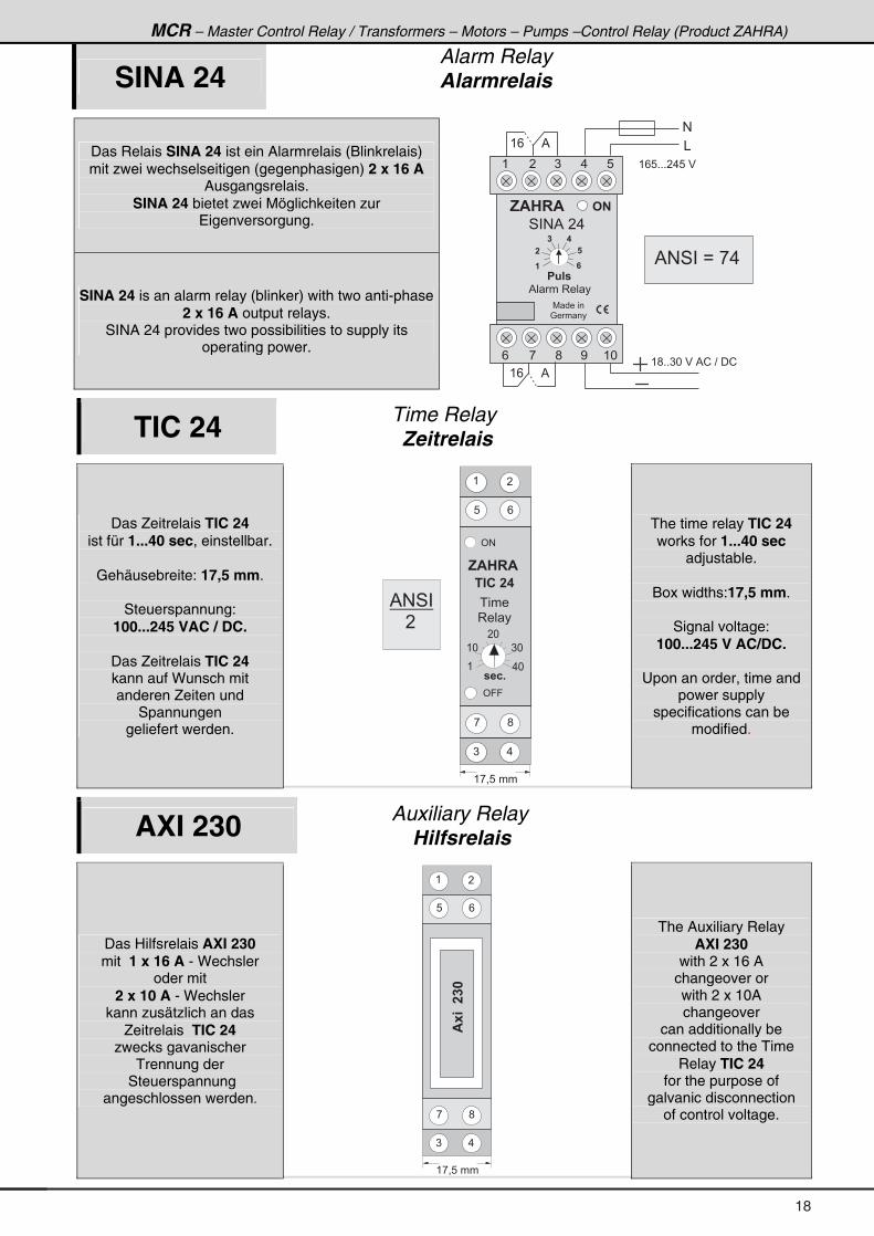
MCR – Master Control Relay / Transformers – Motors – Pumps –Control Relay (Product ZAHRA)
SINA 24 Alarm Relay Alarmrelais
Das Relais SINA 24 ist ein Alarmrelais (Blinkrelais) mit zwei wechselseitigen (gegenphasigen) 2 x 16 A
Ausgangsrelais. SINA 24 bietet zwei Möglichkeiten zur
Eigenversorgung.
SINA 24 is an alarm relay (blinker) with two anti-phase 2 x 16 A output relays.
SINA 24 provides two possibilities to supply its operating power.
#
( / � � � � � %
/ <;, ( *
( ) .� 8
# �
7 � � � � �
: � � � �
, $ � � $
% � � � 3 � � �
�
� 8 � �
( / � � � � � %
&
( / 8 + + + � . 8 � $
( ; + + ) * � $ � % ! � ? � � !
�
� �
�
4 � # % � � .
% # 4 � � B � , .
TIC 24 Time Relay Zeitrelais
Das Zeitrelais TIC 24 ist für 1...40 sec, einstellbar.
Gehäusebreite: 17,5 mm.
Steuerspannung:
100...245 VAC / DC.
Das Zeitrelais TIC 24 kann auf Wunsch mit anderen Zeiten und
Spannungen geliefert werden.
' #
' 9 9
, $ � � $
� " � � � �
( �
/8
, ;
.)
( , = 8 � � �
� � 2 +
( . *
( * ) *
� *
� � � �
3 � � �
% # 4 �
� � � �
The time relay TIC 24 works for 1...40 sec
adjustable.
Box widths:17,5 mm.
Signal voltage: 100...245 V AC/DC.
Upon an order, time and
power supply specifications can be
modified.
AXI 230 Auxiliary Relay Hilfsrelais
Das Hilfsrelais AXI 230 mit 1 x 16 A - Wechsler
oder mit 2 x 10 A - Wechsler
kann zusätzlich an das Zeitrelais TIC 24
zwecks gavanischer Trennung der
Steuerspannung angeschlossen werden.
( �
/8
, ;
.)
$- �����
( , = 8 � � �
The Auxiliary Relay AXI 230
with 2 x 16 A changeover or with 2 x 10A changeover
can additionally be connected to the Time
Relay TIC 24 for the purpose of
galvanic disconnection of control voltage.
18
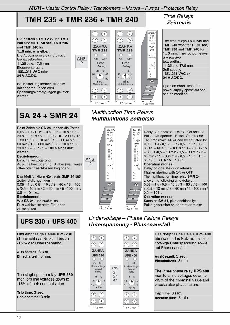
MCR – Master Control Relay / Transformers – Motors – Pumps –Protection Relay
TMR 235 + TMR 236 + TMR 240 Time Relays Zeitrelais
Die Zeitrelais TMR 235 und TMR 240 sind für 1...50 sec, TMR 236 und TMR 240 für 1...6 min. einstellbar. Die Ausgangsrelais sind passiv. Gehäusebreiten: 11,25 bzw. 17,5 mm. Eigenversorgung: 165...245 VAC oder 24 V AC/DC. Bei Bestellung können Modelle mit anderen Zeiten oder Spannungsversorgungen geliefert werden.
( 8
( /
( ;
% (
% �
% )
- -
- -
( ( = � 8 � � �
' #
' 9 9
� % �
, $ � � $
8
(*
*=8
� � �
' # ' 9 9
, $ � � $
� % � � � �
( �
/8
, ;
.)
� � � +
� � � �
3 � � �
( , = 8 � � �
( /
� 8
) .
' # ' 9 9
, $ � � $
� % � � � � �
( �
/8
, ;
.)
� � � +
( 8 *
( * . *
� * ) *
� � � �
3 � � �
( , = 8 � � �
7 � � � � � � : � � � �
7 � � � � � �
: � � � �
7 � � � � � � : � � � �
% # 4 �
� � � �
The time relays TMR 235 und TMR 240 work for 1...50 sec, TMR 236 and TMR 240 for 1...6 min. Their output relays are passive. Box widths: 11,25 and 17,5 mm. Self supply: 165...245 VAC or 24 V AC/DC. Upon an order, time and power supply specifications can be modified.
SA 24 + SMR 24 Multifunction Time Relays Multifunktions-Zeitrelais
Beim Zeitrelais SA 24 können die Zeiten 0,05 – 1 s / 0,15 – 3 s / 0,5 – 10 s / 1,5 – 30 s/3 – 60 s / 5 – 100 s / 10 – 200 s / 15 – 300 s /0,5 – 10 min / 1,5 – 30 min / 3 – 60 min / 15 – 300 min / 0,5 – 10 h / 1,5 – 30 h / 3 – 60 h / 5 – 100 h eingestellt werden. Betriebsmodi: Einschaltverzögerung, Ausschaltverzögerung, Blinker (wahlweise offen oder geschlossen beginnend) Das Multifunktions-Zeitrelais SMR 24 läßt Zeiteinstellungen von 0,05 – 1 s / 0,5 – 10 s / 3 – 60 s / 5 – 100 s /0,5 – 10 min / 3 – 60 min / 5 –100 min / 0,5 – 10 h zu. Betriebsmodi: Wie SA 24, und zusätzlich: Puls wahlweise beim Ein- oder Ausschalten
( 8
( /
( ;
% (
% �
% )
- -
- -
( ( = � 8 � � �
' #
' 9 9
� $ � � �
( 8
( /
( ;
% (
% �
% )
- -
- -
( ( = � 8 � � �
' #
' 9 9
8
(*
*=8
� % �
, $ � � $ , $ � � $
� �
(
�
)
.
(
�
)
.
8
/
8
(*
*=8
% # 4 �
� � � �
Delay- On operate - Delay - On release Pulse- On operate - Pulse- On release The time relay SA 24 can be adjusted for 0,05 – 1 s / 0,15 – 3 s / 0,5 – 10 s / 1,5 – 30 s/3 – 60 s / 5 – 100 s / 10 – 200 s / 15 – 300 s /0,5 – 10 min / 1,5 – 30 min / 3 – 60 min / 15 – 300 min / 0,5 – 10 h / 1,5 – 30 h / 3 – 60 h / 5 – 100 h. Operation modes: Delay on operate or on release Flasher starting with ON or OFF The multifunction time relay SMR 24 allows the following time delays : 0,05 – 1 s / 0,5 – 10 s / 3 – 60 s / 5 – 100 s /0,5 – 10 min / 3 – 60 min / 5 –100 min / 0,5 – 10 h . Operation modes: Same as SA 24, plus additionally: Pulse generation on operate or relase.
UPS 230 + UPS 400 Undervoltage – Phase Failure Relays Unterspannung - Phasenausfall
Das einphasige Relais UPS 230 überwacht das Netz auf bis zu -15%-iger Unterspannung. Auslösezeit: 3 sec. Einschaltzeit: 3 min.
Das dreiphasige Relais UPS 400 überwacht das Netz auf bis zu -15%-ige Unterspannung sowie auf Phasenausfall. Auslösezeit: 3 sec. Einschaltzeit: 3 min.
The single-phase relay UPS 230 monitors line voltages down to -15% of their nominal value. Trip time: 3 sec. Reclose time: 3 min.
' # ' 9 9
, $ � � $
' � � � � � �
( �
/8
, ;
.)
( , = 8 � � �
� � � � � � � � �
! � � � � �
3 � � �
& ' � 5
( 8 (
( � )
< /
' # ' 9 9
, $ � � $
' � � � � � �
( �
/8
, ;
.)
( , = 8 � � �
� � � � � � � � �
! � � � � �
3 � � �
& ' � 5
( 8 (
( � )
< /
% # 4 �
� � � �
� � � ,
� � . , �
The three-phase relay UPS 400 monitors line voltages down to -15% of their nominal value and checks also phase failure. Trip time: 3 sec. Reclose time: 3 min.
19
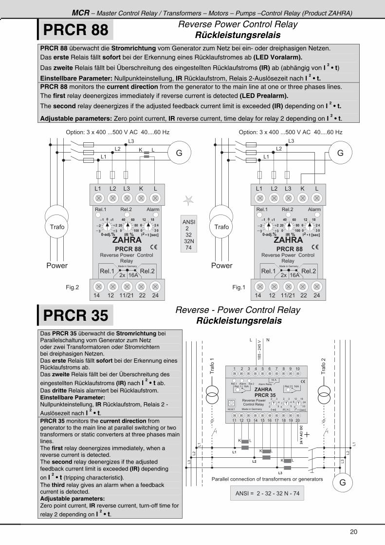
MCR – Master Control Relay / Transformers – Motors – Pumps –Control Relay (Product ZAHRA)
PRCR 88 Reverse Power Control Relay Rückleistungsrelais
PRCR 88 überwacht die Stromrichtung vom Generator zum Netz bei ein- oder dreiphasigen Netzen. Das erste Relais fällt sofort bei der Erkennung eines Rücklaufstromes ab (LED Voralarm).
Das zweite Relais fällt bei Überschreitung des eingestellten Rücklaufstroms (IR) ab (abhängig von I 2 • t)
Einstellbare Parameter: Nullpunkteinstellung, IR Rücklaufstrom, Relais 2-Auslösezeit nach I 2 • t.
PRCR 88 monitors the current direction from the generator to the main line at one or three phases lines. The first relay deenergizes immediately if reverse current is detected (LED Prealarm).
The second relay deenergizes if the adjusted feedback current limit is exceeded (IR) depending on I 2 • t.
Adjustable parameters: Zero point current, IR reverse current, time delay for relay 2 depending on I 2 • t.
@ &
& (
& �
& )
� � � �
9 � � + �
' � � � � � 2 � ) � � � . * * � + + + 8 * * � $ � % ! � � . * + + + + / * � 0 1
� � �
:& (
& �
& )
� � � �
9 � � + (
:
� � �
& ( & ) @& � &
3 � � + ( 3 � � + � % � �
, $ � � $
� � � � �
3 � � � � � � � � � � � ! � � � � � �
3 � � �
( . ( � ( ( ? � ( � � � .
3 � � + (
7 � � � � � � : � � � �
� � � � ( / %
� & � B C + 5
�
�
��
�
" � � 5
�
� �
� � �
� � �
� � �
� �
" � � � A � 6 � > � � 2 ?�
� � ��
�
�
3 � � + �
' � � � � � 2 � ) � � � . * * � + + + 8 * * � $ � % ! � � . * + + + + / * � 0 1
& ( & ) @& � &
3 � � + ( 3 � � + � % � �
, $ � � $
� � � � �
3 � � � � � � � � � � � ! � � � � � �
3 � � �
( . ( � ( ( ? � ( � � � .
3 � � + (
7 � � � � � � : � � � �
� � � � ( / %
� & � B C + 5
�
�
��
�
" � � 5
�
� �
� � �
� � �
� � �
� �
" � � � A � 6 � > � � 2 ?�
� � ��
�
�
3 � � + �
% # 4 �
� � �
� � ) �
� ) � #
� � , .
PRCR 35 Reverse - Power Control Relay Rückleistungsrelais
Das PRCR 35 überwacht die Stromrichtung bei Parallelschaltung vom Generator zum Netz oder zwei Transformatoren oder Stromrichtern bei dreiphasigen Netzen. Das erste Relais fällt sofort bei der Erkennung eines Rücklaufstroms ab. Das zweite Relais fällt bei der Überschreitung des
eingestellten Rücklaufstroms (IR) nach I 2 • t ab.
Das dritte Relais alarmiert bei Rücklaufstrom. Einstellbare Parameter: Nullpunkteinstellung, IR Rücklaufstrom, Relais 2 -
Auslösezeit nach I 2 • t.
PRCR 35 monitors the current direction from generator to the main line at parallel switching or two transformers or static converters at three phases main lines. The first relay deenergizes immediately, when a reverse current is detected. The second relay deenergizes if the adjusted feedback current limit is exceeded (IR) depending
on I 2 • t (tripping characteristic).
The third relay gives an alarm when a feedback current is detected. Adjustable parameters: Zero point current, IR reverse current, turn-off time for
relay 2 depending on I 2 • t.
( � ) . 8 / , ; < ( *
( ( ( � ( ) ( . ( 8 ( / ( , ( ; ( < � *
� ���( (;8�-��.8�$
& #
�����$����
&(
( �
&�
( �
( �
&)
&
&(
&�
&)
:� � � � � � � � � � � � � � � � � � � � � � � � � � � � � � � � � � � � � �
� ����
@
&@
&@
3 � � + ( ( / % 3 � � + � ( / %
( / � %
% � � � 3 � � �
7 � � � � � � : � � � �
*) *
/ � .
( � ( ;
*8
(.
� )
� � � � L � � � E � � � F�
3 � � + ( 3 � � + �
* 8
(.
� )
3 � 4 � �
% � �
, $ � � $
� � � � � � �
* - � > � 3 � E � % � F
3 � � � � � � � � �
� ! � � � � � � 3 � � �
% # 4 � � B � � � � - � ) � � - � ) � � # � - � , .
20
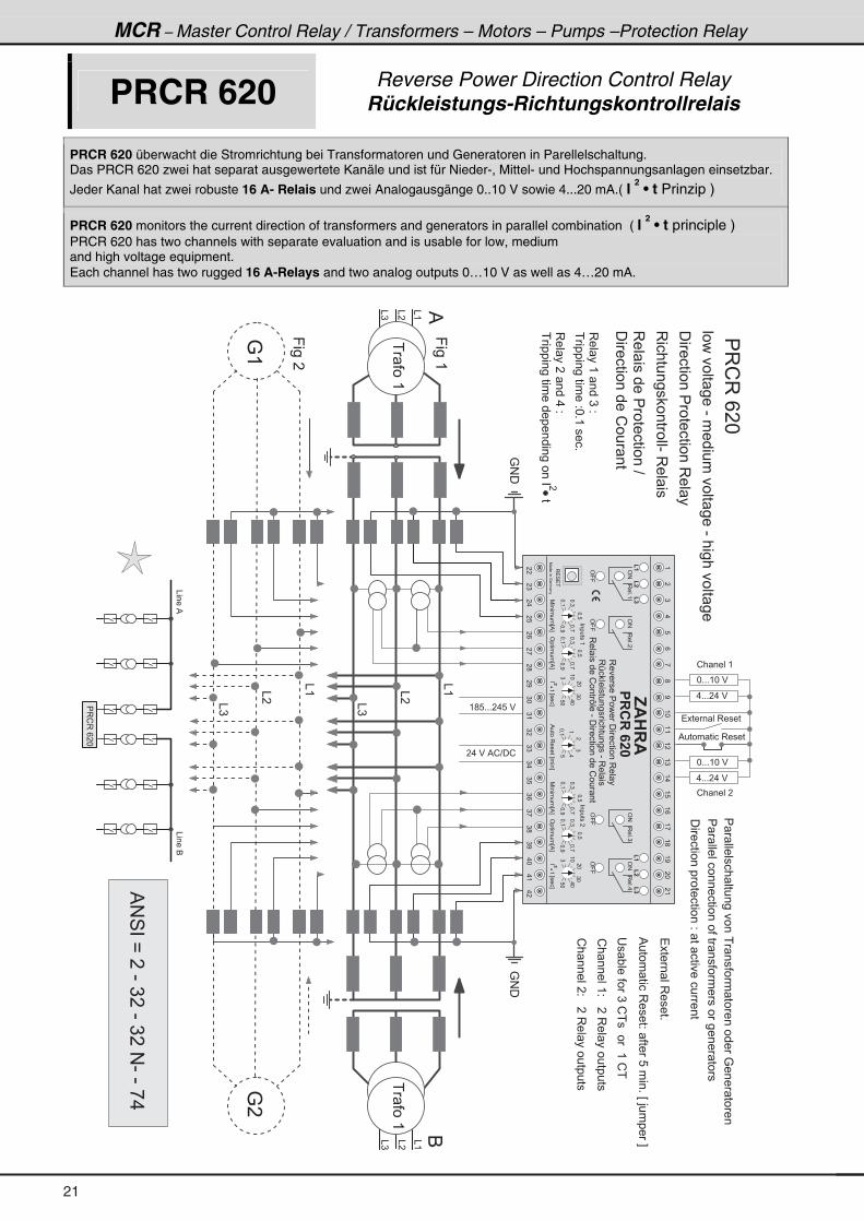
@
MCR – Master Control Relay / Transformers – Motors – Pumps –Protection Relay
PRCR 620 Reverse Power Direction Control Relay Rückleistungs-Richtungskontrollrelais
PRCR 620 überwacht die Stromrichtung bei Transformatoren und Generatoren in Parellelschaltung. Das PRCR 620 zwei hat separat ausgewertete Kanäle und ist für Nieder-, Mittel- und Hochspannungsanlagen einsetzbar.
Jeder Kanal hat zwei robuste 16 A- Relais und zwei Analogausgänge 0..10 V sowie 4...20 mA.( I 2 • t Prinzip )
PRCR 620 monitors the current direction of transformers and generators in parallel combination ( I 2 • t principle )
PRCR 620 has two channels with separate evaluation and is usable for low, medium and high voltage equipment. Each channel has two rugged 16 A-Relays and two analog outputs 0…10 V as well as 4…20 mA.
&�
&(
&)
:#�
:#�
* + + + ( * � $
. + + + � . � $
* + + + ( * � $
! � � � � � (
! � � � � � �
� � � � � � � 3 � � � �
% � � � � � � � � 3 � � � �
. + + + � . � $
( ; 8 + + + � . 8 � $
� . � $ � % ! ? � !
� ������� ���������� ����� ���������:��� ����
� �������������������� �������������� ���
����� ��3����+
%���� ����3����2� ����8����+�E�>�����F
�� "������)�!�������(�!�
!� �����(2�����3�� ���������
!� ������2�����3�� ���������
�������������������3�� �
9���(
�3!3�/�*
3�������� ������-�3�� ��
3�� ����������������?
������������!�� ��
3�� ��(� ���)�2�
�����������
��2*+(����+
3�� ���� ���.�2�
�����������
����������������������
�������������������2� �� ����������
� ���(
� ���(
&�
&(
&)
:(
:�
9����
������� ���-����������� ���-��������� ��
�3!3�/�*
&����%
&����6
&(
&�
&)
%
&(
&�
&)
6
�
%#4��B���-�)��-�)��#-�-�,.
3��+(
(�
).
8/
,;
<(*
((
(�
()
(.
(8
(/
(,
(;
(<
�*
�(
(�
(�
(�
(�
(�
,$��$
(�
��
�)
�.
�8
�/
�,
�;
�<
)*
)(
)�
))
).
)8
)/
),
);
)<
.*
.(
.�
����� ��
7 ������:�� ��
�������(
�L
�
7����
��E%F
3�4�� 3��+(
'#
'99
3��+�
'#
'99
3��+)
'#
'99
3��+.
'#
'99
'����
��E%F
*=)
*=8
*=,
*=<
*=(
*=)
*=8
*=,
*=<
*=(
(*
�*
.*
8*
)
�������E���F
)*
�L
�
7����
��E%F'����
��E%F
*=)
*=8
*=,
*=<
*=(
*=)
*=8
*=,
*=<
*=(
(*
�*
.*
8*
)
�������E���F
)*
��������
3�������������������3�� ��
3A� ������������������-�3�� ��
(
�
.8*=(
%����3�����E���F
)
3�� ������!���M���-�������������!�� ��
21
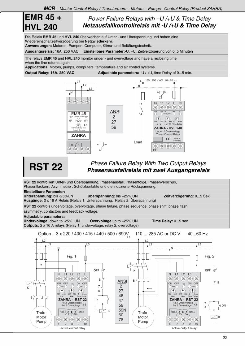
22
MCR – Master Control Relay / Transformers – Motors – Pumps –Control Relay (Product ZAHRA)
EMR 45 +
HVL 240 Power Failure Relays with –U /+U & Time Delay
Netzausfallkontrollrelais mit -U /+U & Time Delay
Die Relais EMR 45 und HVL 240 überwachen auf Unter - und Überspannung und haben eine Wiedereinschaltzeitverzögerung bei Netzwiederkehr. Anwendungen: Motoren, Pumpen, Computer, Klima- und Belüftungstechnik.
Ausgangsrelais: 16A, 250 VAC. Einstellbare Parameter:-U, +U, Zeitverzögerung von 0..5 Minuten
The relays EMR 45 and HVL 240 monitor under - and overvoltage and have a reclosing time when the line returns again. Applications: Motors, pumps, computers, temperature and air control systems
Output Relay: 16A. 250 VAC Adjustable parameters: -U / +U, time Delay of 0...5 min.
� � � � � � � � � � � � . 4
� � � � ' # �
� � � � � � ! � � � � � � 3 � � � �
, $ � � $ � & � � � ( � � � �
7 � � � � �
: � � � �
� � � � - � ? � ' � - � � � � �
( . ( � &( ( #
� �
' # �
� � � � � � � � �
' � > � � � ? � . � � � � � � �' � > � � � ?
� �
( �
( (
( .
( ; 8 + + + � 8 * � $ � % ! � � � . * � - � / * � 0 1 �
& � �
#
& (
, $ � � $
� 7 3 � . 8� � � � � $ � � � � � � ? � � � � � � � 3 � � �
7 � � � � � � : � � � �
8 / , ;
( / %
( � ) .
' # ' 9 9� � � �
& �
& )
' # � � � � � � � � � � � E � � � F
* 8
( .
� )
((
(.
(�
�
( )
% # 4 �
� � � �
� � ,
� 8 < �
RST 22 Phase Failure Relay With Two Output Relays Phasenausfallrelais mit zwei Ausgangsrelais
RST 22 kontrolliert Unter- und Überspannung, Phasenausfall, Phasenfolge, Phasenverschub, Phasenflackern, Asymmetrie , Schützkontakte und die induzierte Rückspannung. Einstellbare Parameter: Unterspannung: bis -25%UN Überspannung: bis +25% UN Zeitverzögerung: 0...5 Sek Ausgänge: 2 x 16 A Relais (Relais 1: Unterspannung, Relais 2: Überspannung)
RST 22 controls undervoltage, overvoltage, phase failure, phase sequence, phase shift, phase flash, asymmetry, contactors and feedback voltage. Adjustable parameters: Undervoltage: down to -25% UN Overvoltage up to +25% UN Time Delay: 0...5 sec Outputs: 2 x 16 A relays (Relay 1: undervoltage, relay 2: overvoltage)
& (
& �
& )
#
6
& (
& �
& )
#
6
,
;' #
6
9 � � + � (
@
@
@
� � �
7 � � �
� � � �
� � �
7 � � �
� � � �
� � � � ' � � � � � � 2 � � ) � � � � � * � ? � . * * � ? � . ( 8 � ? � . . * � ? � 8 * * � ? � / < * $ � � � � � ( ( * � + + + � � ; 8 � % ! � � � � ! � $ � � � � � � . * + + + / * � 0 1
6
# � � # � �
,
;
9 � � + � �
@
& ) & )
� � � � � � � � � � � � � � � � � � � � � � � � � � � � � �
% # 4 �
� � � �
� � ,
� . /
� . ,
� 8 <
� 8 < #
� / *
� , ;
) * * . ( 8 . ( 8 8 * * � 8 � � � �
' 9 9 ' # ' 9 9
, $ � � $ � & � � � � � � � �
� � � � � � � � �
# & � & )& ( &
'
' #
� � � + � � � � + �
3 � � + � � ' � � � � � �
3 � � + ( � � � � � � � � � �
/ ; < ( *,
3 � � + ( 3 � � + �
7 � � � � � � : � � � �
� � � � ( / %
'
) * * . ( 8 . ( 8 8 * * � 8 � � � �
' 9 9 ' # ' 9 9
, $ � � $ � & � � � � � � � �
� � � � � � � � �
# & � & )& ( &
'
' #
� � � + � � � � + �
3 � � + � � ' � � � � � �
3 � � + ( � � � � � � � � � �
/ ; < ( *,
3 � � + ( 3 � � + �
7 � � � � � � : � � � �
� � � � ( / %
'
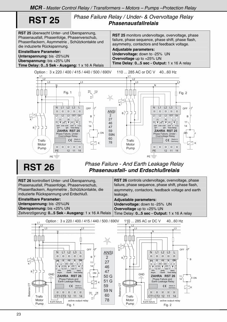
MCR – Master Control Relay / Transformers – Motors – Pumps –Protection Relay
RST 25 Phase Failure Relay / Under- & Overvoltage RelayPhasenausfallrelais
RST 25 überwacht Unter- und Überspannung, Phasenausfall, Phasenfolge, Phasenverschub, Phasenflackern, Asymmetrie , Schützkontakte und die induzierte Rückspannung. Einstellbare Parameter: Unterspannung: bis -25%UN Überspannung: bis +25% UN Time Delay: 0...5 Sek - Ausgang: 1 x 16 A Relais
RST 25 monitors undervoltage, overvoltage, phase failure, phase sequence, phase shift, phase flash, asymmetry, contactors and feedback voltage. Adjustable parameters: Undervoltage: down to -25% UN Overvoltage up to +25% UN Time Delay: 0...5 sec - Output: 1 x 16 A relay
& (
& �
& )
#
6
& (
& �
& )
#
6
9 � � + � (
@
� � �
7 � � �
� � � �
� � �
7 � � �
� � � �
9 � � + � �
& ) & )
((
(.
(�
� � � � ' � � � � � � 2 � � ) � � � � � * � ? � . * * � ? � . ( 8 � ? � . . * � ? � 8 * * � ? � / < * $ � � � � � ( ( * � + + + � � ; 8 � % ! � � � � ! � $ � � � � . * + + + / * � 0 1
� �
6
' 9 9
( (
( .
@
' #
6
' 9 9
( (
( .
@
' #
� �
% # 4 �
� � � �
� � ,
� . /
� . ,
� 8 <
� 8 < #
� / *
� , ; �
� � ( � ( ( ( .
� � �
� � �� � �
� �
� � �� � �
� �
�
� �
�
7 � � � � �
: � � � �
' � � � � � � � 3 � � �
, $ � � $ � � � � � � � �
� � � � � 9 � � � � = � � � � � � -
& ( & � & ) ' 9 9 ' #
' D � . � � � � � � �'
� � � � � � � � � � � � � � � � � � � � � 2 +
# & ( & � & ) &
� � ( � ( ( ( .
� � �
� � �� � �
� �
� � �� � �
� �
�
� �
�
7 � � � � �
: � � � �
' � � � � � � � 3 � � �
, $ � � $ � � � � � � � �
� � � � � 9 � � � � = � � � � � � -
& ( & � & ) ' 9 9 ' #
' D � . � � � � � � �'
� � � � � � � � � � � � � � � � � � � � � 2 +
# & ( & � & ) &
@
RST 26 Phase Failure - And Earth Leakage Relay Phasenausfall- und Erdschlußrelais
RST 26 kontrolliert Unter- und Überspannung, Phasenausfall, Phasenfolge, Phasenverschub, Phasenflackern, Asymmetrie , Schützkontakte, die induzierte Rückspannung und Erdschluß. Einstellbare Parameter: Unterspannung: bis -25%UN Überspannung: bis +25% UN Zeitverzögerung: 0...5 Sek - Ausgang: 1 x 16 A Relais
RST 26 controls undervoltage, overvoltage, phase failure, phase sequence, phase shift, phase flash, asymmetry, contactors, feedback voltage and earth leakage. Adjustable parameters: Undervoltage: down to -25% UN Overvoltage up to +25% UN Time Delay: 0...5 sec - Output: 1 x 16 A relay
& (
& �
& )
#
6
& (
& �
& )
#
6
( (
( .' #
6
9 � � + � (
@
@
� � �
7 � � �
� � � �
6
' 9 9 ' 9 9
( (
( .
((
(�
(.
� � � � � � � � � � � � � � �
@
& ) & )
� � � - � � � � �
6 � ����!�
: # �
� � �
7 � � �
� � � �
: # �
� � � � � � � � � � � � � � �� � � - � � � � �
6 � ����!�
� � � � ' � � � � � � 2 � � ) � � � � � * � ? � . * * � ? � . ( 8 � ? � . . * � ? � 8 * * � ? � / < * $ � � � � � ( ( * � + + + � � ; 8 � % ! � � � � ! � $ � � � � � � . * + + + / * � 0 1
9 � � + � �
% # 4 �
� � � �
� � ,
� . /
� . ,
8 * � :
8 ( � :
8 <
8 < � #
� / *
� , ;
� � 5 > . $ ? � > � � 2 ?
' D ' " ! # �-
7 � � � � �
: � � � �
$ � � . + " � ! � 1 6 ; � . � � � � � � �
� � � � � 9 � � � � � � �
# & � & )& ( &
! � ( ( � ( (! � � ( .
( 8
) ( �
/ <
) * 8 * *
( * * . * *
� * * ) * *
* 8
( .
� )
*
, $ � � $ � � � � � � � �
� � � � & � � � � 3 � � �
� � 5 > . $ ? � > � � 2 ?
' D ' " ! # �-
7 � � � � �
: � � � �
$ � � . + " � ! � 1 6 ; � . � � � � � � �
� � � � � 9 � � � � � � �
# & � & )& ( &
! � ( ( � ( (! � � ( .
( 8
) ( �
/ <
) * 8 * *
( * * . * *
� * * ) * *
* 8
( .
� )
*
, $ � � $ � � � � � � � �
� � � � & � � � � 3 � � �
@
' #
23
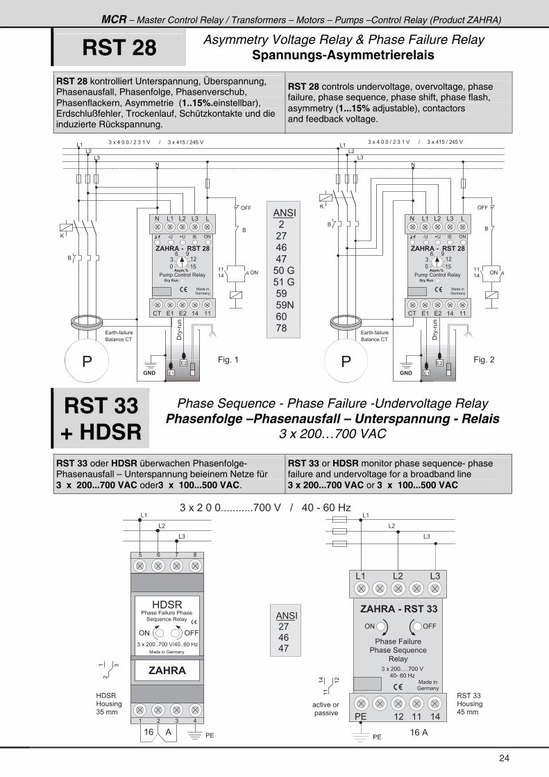
MCR – Master Control Relay / Transformers – Motors – Pumps –Control Relay (Product ZAHRA)
RST 28 Asymmetry Voltage Relay & Phase Failure Relay Spannungs-Asymmetrierelais
RST 28 kontrolliert Unterspannung, Überspannung, Phasenausfall, Phasenfolge, Phasenverschub, Phasenflackern, Asymmetrie (1..15%.einstellbar), Erdschlußfehler, Trockenlauf, Schützkontakte und die induzierte Rückspannung.
RST 28 controls undervoltage, overvoltage, phase failure, phase sequence, phase shift, phase flash, asymmetry (1...15% adjustable), contactors and feedback voltage.
& (
& �
& )
) � � � . � * � * � ? � � � ) � ( � $ � � � � � � ? � � � � � ) � � � . ( 8 � ? � � . 8 � $& (
& �
& )
#
' 9 9
6
( (
( .' #
) � � � . � * � * � ? � � � ) � ( � $ � � � � � � ? � � � � � ) � � � . ( 8 � ? � � . 8 � $
��-��
� �
� (
� � � - � � � � �
6 � � � � � ! �
� �9 � � + � �
6
� � � - � � � � �
6 � � � � � ! �
#
' 9 9
6
( (
( .' #
��-��
� �
� (� � �
9 � � + � (
6
� � �
% # 4 �
� � � �
� � ,
� . /
� . ,
8 * � :
8 ( � :
� 8 <
� 8 < #
� / *
� , ;
- � � � ' #
, $ � � $ � & � � � � � � �
� � � � � ! � � � � � � 3 � � �
! � � � ( .� ( ( (
$ � � . + 5
� �
7 � � � � �
: � � � �
� 1 � � � 8 4
# & � & )& ( &
* ( 8
) ( �
/ <
- � � � ' #
, $ � � $ � & � � � � � � �
� � � � � ! � � � � � � 3 � � �
! � � � ( .� ( ( (
$ � � . + 5
� �
7 � � � � �
: � � � �
� 1 � � � 8 4
# & � & )& ( &
* ( 8
) ( �
/ <
@
@
RST 33 + HDSR
Phase Sequence - Phase Failure -Undervoltage Relay Phasenfolge –Phasenausfall – Unterspannung - Relais
3 x 200…700 VAC
RST 33 oder HDSR überwachen Phasenfolge- Phasenausfall – Unterspannung beieinem Netze für 3 x 200...700 VAC oder3 x 100...500 VAC.
RST 33 or HDSR monitor phase sequence- phase failure and undervoltage for a broadband line 3 x 200...700 VAC or 3 x 100...500 VAC
) � � � � � * � * + + + + + + + + + + + , * * � $ � � � ? � � � . * � - � / * � 0 1
, $ � � $
0 � 4 3
' # ' 9 9
7 � � � � � � : � � � �
( � ) .
8 / , ;
( / %
& (
& �
& )
� �
, $ � � $ � & � � � � � � �
& ( & � & )
� � ( � ( ( ( .
7 � � � � �
: � � � �
' # ' 9 9
) � � � � * * + + + + + , * * � $
. * - � / * � 0 1
((
(.
(�
� �
�
( )
( / � %
� � � � � 9 � � � �
� � � � � 4 � � � � � � �
3 � � �
� � � � � 9 � � � � � � � � �
4 � � � � � � � � 3 � � �
) � � � � * * + + , * * � $ ? . * + + / * � 0 1
� � � � � �
� � � � � �
0 � 4 3
0 � � � � � �
) 8 � � �
3 4 � � ) )
0 � � � � � �
. 8 � � �
% # 4 �
� � ,
� . /
� . ,
& (
& �
& )
24
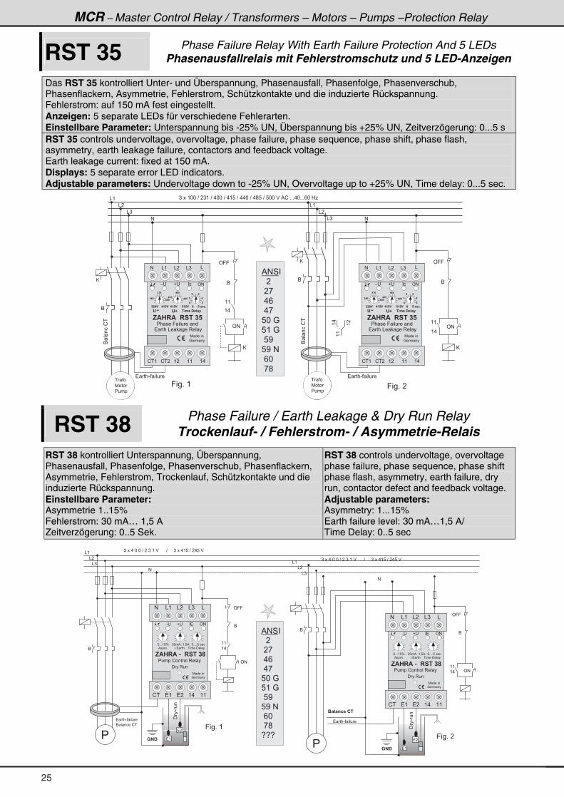
MCR – Master Control Relay / Transformers – Motors – Pumps –Protection Relay
RST 35 Phase Failure Relay With Earth Failure Protection And 5 LEDs Phasenausfallrelais mit Fehlerstromschutz und 5 LED-Anzeigen
Das RST 35 kontrolliert Unter- und Überspannung, Phasenausfall, Phasenfolge, Phasenverschub, Phasenflackern, Asymmetrie, Fehlerstrom, Schützkontakte und die induzierte Rückspannung. Fehlerstrom: auf 150 mA fest eingestellt. Anzeigen: 5 separate LEDs für verschiedene Fehlerarten. Einstellbare Parameter: Unterspannung bis -25% UN, Überspannung bis +25% UN, Zeitverzögerung: 0...5 s RST 35 controls undervoltage, overvoltage, phase failure, phase sequence, phase shift, phase flash, asymmetry, earth leakage failure, contactors and feedback voltage. Earth leakage current: fixed at 150 mA. Displays: 5 separate error LED indicators. Adjustable parameters: Undervoltage down to -25% UN, Overvoltage up to +25% UN, Time delay: 0...5 sec.
& (
& �
& )
#
) � � � ( * * � ? � � ) ( � ? � . * * � ? � . ( 8 � ? � . . * � ? � . ; 8 � ? � 8 * * � $ � % ! � + + + . * + + + / * � 0 1
#
' 9 9
6
( (
( .
' #
' 9 9
6
( (
( .
' #
9 � � + � (
� � � - � � � � �
@ @
& (
& �
& )
6 � ���!�
((
(.
(�
9 � � + � �
� � �
7 � � �
� � � �
6 � ���!�
� � � - � � � � �
� � �
7 � � �
� � � �
( � ( ( ( .
� � �
� � �� � �
� �
� � �� � �
� �
�
� �
�
7 � � � � �
: � � � �
, $ � � $ � � � � � � � �
' #
' D � . � � � � � � �'
� � � � � � � � � � � � � � � � � � � � � 2 +
# & ( & � & ) &
� � � � & � � � � 3 � � �
� � � � � 9 � � � � � � �
� � � � �-
! � ( ! � � ( � ( ( ( .
� � �
� � �� � �
� �
� � �� � �
� �
�
� �
�
7 � � � � �
: � � � �
, $ � � $ � � � � � � � �
' #
' D � . � � � � � � �'
� � � � � � � � � � � � � � � � � � � � � 2 +
# & ( & � & ) &
� � � � & � � � � 3 � � �
� � � � � 9 � � � � � � �
� � � � �-
! � ( ! � �
6
6
@
@
% # 4 �
� � � �
� � ,
� . /
� . ,
8 * � :
8 ( � :
� 8 <
8 < � #
� / *
� , ;
RST 38 Phase Failure / Earth Leakage & Dry Run Relay Trockenlauf- / Fehlerstrom- / Asymmetrie-Relais
RST 38 kontrolliert Unterspannung, Überspannung, Phasenausfall, Phasenfolge, Phasenverschub, Phasenflackern, Asymmetrie, Fehlerstrom, Trockenlauf, Schützkontakte und die induzierte Rückspannung. Einstellbare Parameter: Asymmetrie 1..15% Fehlerstrom: 30 mA… 1,5 A Zeitverzögerung: 0..5 Sek.
RST 38 controls undervoltage, overvoltage phase failure, phase sequence, phase shift phase flash, asymmetry, earth failure, dry run, contactor defect and feedback voltage. Adjustable parameters: Asymmetry: 1...15% Earth failure level: 30 mA…1,5 A/ Time Delay: 0..5 sec
& (
& �
& )
#
) � � � . � * � * � ? � � � ) � ( � $ � � � � � � ? � � � � � ) � � � . ( 8 � ? � � . 8 � $
& (
& �
& )
#
6
( (
( .
' #
' 9 9
6
( (
( . ' #
) � � � . � * � * � ? � � � ) � ( � $ � � � � � � ? � � � � � ) � � � . ( 8 � ? � � . 8 � $
9 � � + � (
��-��
� �
� (
�
� � � - � � � � �� � � - � � � � �
6
6 � � � � � ! �
� � � � 4 2 � � � �
� � �
��-��
� �
� (
�
� � �
9 � � + � �
' 9 9
6
* + + + ( 8 J ) * � % + + ( = 8 % * + + + + 8 � � � �
- � � � ' #
, $ � � $ � & � � � � � � �
� � � � � � � � �
� � � � � ! � � � � � � 3 � � �
! � � � ( .� ( ( (
% � � � + � � � � �
� �
7 � � � � �
: � � � �
� � � 3 � �
# & � & )& ( &
* + + + ( 8 J ) * � % + + ( = 8 % * + + + + 8 � � � �
- � � � ' #
, $ � � $ � & � � � � � � �
� � � � � � � � �
� � � � � ! � � � � � � 3 � � �
! � � � ( .� ( ( (
% � � � + � � � � �
� �
7 � � � � �
: � � � �
� � � 3 � �
# & � & )& ( &
% # 4 �
� � � �
� � ,
� . /
� . ,
8 * � :
8 ( � :
� 8 <
8 < � #
� / *
� , ;
5 5 5 �
25
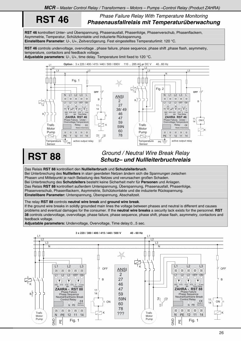
MCR – Master Control Relay / Transformers – Motors – Pumps –Control Relay (Product ZAHRA)
RST 46 Phase Failure Relay With Temperature Monitoring Phasenausfallrelais mit Temperaturüberwachung
RST 46 kontrolliert Unter- und Überspannung, Phasenausfall, Phasenfolge, Phasenverschub, Phasenflackern, Asymmetrie, Temperatur, Schützkontakte und induzierte Rückspannung. Einstellbare Parameter: U-, U+, Zeitverzögerung. Fest eingestelltes Temperaturlimit: 120 °C.
RST 46 controls undervoltage, overvoltage , phase failure, phase sequence, phase shift ,phase flash, asymmetry, temperature, contactors and feedback voltage. Adjustable parameters: U-, U+, time delay. Temperature limit fixed to 120 °C.
� � � � � � � �
� 4 � � � � � �
& (
& �
& )
#
6
& (
& �
& )
#
6
( (
( .' #
6
9 � � + � (
@
� � �
7 � � �
� � � �
� � � � # � 6 3 4 � 2 � � ) � � � � � * � ? � . * * � ? � . ( 8 � ? � . . * � ? � 8 * * � ? � / < * $ � � � � � ( ( * � + + + � � ; 8 � % ! � � � � ! � $ � � � � � � . * + + + / * � 0 1
6
# � � # � �
( (
( .
((
(�
(.
� � � � � � � � � � � � � � �
9 � � + � �
@
� � � � � � � � � � � � � � �
& ) & )
� �
� � �
7 � � �
� � � �
� � � � � � � �
� 4 � � � �
% # 4 �
� � � � �
� � � � ,
� ) ; ? � . <
� � � . /
� � � . ,
� � � 8 <
� � 8 < #
� � � / *
� � � , ;� � ( � ( ( ( .
� � �
� � �� � �
� �
� � �� � �
� �
�
� �
�
7 � � � � � : � � � �
' � � � � � � = � � � � � � � �
, $ � � $ � � � � � � �
� � � � � 9 � � � � = � � � � � � � - �
& ( & � & ) ' 9 9 ' #
' D � . � � � � � � �'
� � � � � � � � � � � � � � � � � � � � � 2 +
# & ( & � & ) &
�
3 � � �
� � ( � ( ( ( .
� � �
� � �� � �
� �
� � �� � �
� �
�
� �
�
7 � � � � � : � � � �
' � � � � � � = � � � � � � � �
, $ � � $ � � � � � � �
� � � � � 9 � � � � = � � � � � � � -
& ( & � & ) ' 9 9 ' #
' D � . � � � � � � �'
� � � � � � � � � � � � � � � � � � � � � 2 +
# & ( & � & ) &
�
3 � � �
@
@
RST 88 Ground / Neutral Wire Break Relay Schutz– und Nullleiterbruchrelais
Das Relais RST 88 kontrolliert den Nullleiterbruch und Schutzleiterbruch. Bei Unterbrechung des Nullleiters in starr geerdeten Netzen ändern sich die Spannungen zwischen Phasen und Mittelpunkt je nach Belastung des Netzes und verursachen großen Schaden. Bei Unterbrechung des Schutzleiters besteht keine Sicherheit mehr für Personen und Anlagen. Das Relais RST 88 kontrolliert außerdem Unterspannung, Überspannung, Phasenausfall, Phasenfolge, Phasenverschub, Phasenflackern, Asymmetrie, Schützkontakte und die induzierte Rückspannung. Einstellbare Parameter: Unterspannung, Überspannung, Abschaltzeit.
The relay RST 88 controls neutral wire break and ground wire break. If the ground wire breaks in solidly grounded main lines the voltage between phases and neutral is different and causes problems and eventual damages for the consumer. If the neutral wire breaks a security lack exists for the personnel. RST 38 controls undervoltage, overvoltage, phase failure, phase sequence, phase shift, phase flash, asymmetry, contactors and feedback voltage. Adjustable parameters: Undervoltage, Overvoltage, Time delay:0...5 sec.
& (
& �
& )
#
6
� � - � � � � � � � � � � � � � � � � � � � � � � � � � � � � � � � � � � � � � � � � � � � � � & � � � � E
' 9 9
6
( (
( .
' #
' 9 9
6
( (
( .' #
9 � � + � (
@
@ @
��
:#�
9 � � + � (
��
:#�
& (
& �
& )
#
((
(.
(�
� � �
7 � � �
� � � �
� � �
7 � � �
� � � �
) 8 * . ( 8 . ( 8 . , 8 * 8 � � � �
& � ' 9 9 ' #
� � � � � 4 � � � � � � �
, $ � � $ � & � � � � � �
7 � � � � �
: � � � �
� � � � � � � � �
� � � � � 9 � � � �
& � & )& (
# ( � ( ( ( .
' & ' D
& )& (
� �
# � � � � ? � � � � � � � 6 �
! � � � � � � 3 � � �
� �#
) 8 * . ( 8 . ( 8 . , 8 * 8 � � � �
& � ' 9 9 ' #
� � � � � 4 � � � � � � �
, $ � � $ � & � � � � � �
7 � � � � �
: � � � �
� � � � � � � � �
� � � � � 9 � � � �
& � & )& (
# ( � ( ( ( .
' & ' D
& )& (
� �
# � � � � ? � � � � � � � 6 �
! � � � � � � 3 � � �
� �#
@
% # 4 �
� � � �
� � ,
� . /
� . ,
� 8 <
� 8 < #
� / *
� , ;
5 5 5
26
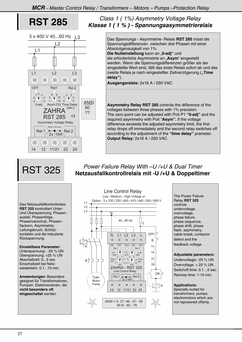
MCR – Master Control Relay / Transformers – Motors – Pumps –Protection Relay
RST 285 Class 1 ( 1%) Asymmetry Voltage Relay Klasse 1 ( 1 % ) - Spannungsasymmetrierelais
Das Spannungs - Asymmetrie- Relais RST 285 misst die Spannungsdifferenzen zwischen drei Phasen mit einer Absolutgenauigkeit von 1%. Die Nulleinstellung kann an „0-adj“ und die erforderliche Asymmetrie an „Asym“ eingestellt werden. Wenn die Spannungsdifferenzen größer als der eingestellte Wert sind, fällt das erste Relais sofort ab und das zweite Relais je nach eingestellter Zeitverzögerung („Time delay“). Ausgangsrelais: 2x16 A / 250 VAC
& (
& �
& )) � � � . * * � $ � . * + + + / * � 0 1
& ( & � & )
' 9 9 3 � � ( 3 � � + �
G % 0 3 %
3 4 � � � ; 8
* - � > +
) )
� �
( (*
% � � � + E J F � � � � � � � � �
( ( 8
) ( �
/ <
* 8
( .
� )
( . ( � ( ( ? � ( � � � .
3 � � + (
7 � � � � � � : � � � �
� � � � ( / %
E � � � + F
% � � � � � � � � $ � � � � � � 3 � � �
3 � � + �
% # 4 �
� / * �
� 5 5
� �
Asymmetry Relay RST 285 controls the difference of the voltages between three phases with 1% precision. The zero point can be adjusted with Poti P1 “0-adj” and the required asymmetry with Poti “Asym”. If the voltage difference exceeds the adjusted asymmetry limit, the first relay drops off immediately and the second relay switches off according to the adjustment of the “time delay” prameter. Output Relay: 2x16 A / 250 VAC
RST 325 Power Failure Relay With –U /+U & Dual Timer Netzausfallkontrollrelais mit -U /+U & Doppeltimer
Das Netzausfallkontrollrelais RST 325 kontrolliert Unter- Und Überspannung, Phasen- ausfall, Phasenfolge, Phasenverschub, Phasen- flackern, Asymmetrie, Leitungsbruch, Schütz- kontakte und die induzierte Rückspannung. Einstellbare Parameter: Unterspannung: -25 % UN Überspannung: +25 % UN Abschaltzeit: 0...5 sec. Einschaltzeit bei Netz- wiederkehr: 0.1...10 min. Anwendungen: Besonders geeignet für Transformatoren, Pumpen, Elektromotoren, die nicht besonders oft eingeschaltet werden .
& (
& �
& )
#
6
' � � � � � � 2 � ) � � � ( * * � ? � � � * � ? � . * * � ? � . ( 8 � ? � . . * � ? � 8 * * � ? � / < * � $ �
' 9 9
6
( (
( .
' #
@
� (
� .
&
� � �
7 � � �
� � � �
& � � � � ! � � � � � � 3 � � �
& � � � - � 7 � � � � � � - � 0 � � � � $ � � � � � � �
. * + + + / * � 0 1
% # 4 � � B � � - � � , - � . / � - � . , - � � 8 < �
� � � � � � � � � � � � � 8 < � # � - � / * � - � , ;
& � � � � ! � � � � � � 3 � � �
3 � � + (
7 � � � � � � : � � � �
� � � � ( / %
' # ' 9 9 ' 9 9' #
� � � + � �
) * * . ( 8 8 * *
* 8 �
G % 0 3 % � - � 3 4 � � ) � 8
# & � & )& (
� �
* = (
� � �� � �( * �
� � � �
' #
� � � �
' 9 9
E � � F
(
�
�
)
.
. /
;
� � � �
3 � � + �
&
( . ( � ( ( ? � ( � � � .
� � � + � �
@
The Power Failure Relay RST 325 controls undervoltage, overvoltage, phase failure, phase sequence, phase shift, phase flash, asymmetry, cable break, contactor defect and the feedback voltage. Adjustable parameters: Undervoltage: -25 % UN Overvoltage: + 25 % UN Switchoff time: 0.1…5 sec.Reclose time: 1-10 min. Applications: Specially suited for transformers, pumps, electromotors which are not repowered oftenly.
27
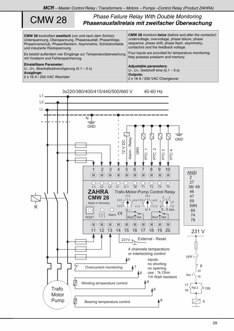
MCR – Master Control Relay / Transformers – Motors – Pumps –Control Relay (Product ZAHRA)
CMW 28 Phase Failure Relay With Double Monitoring Phasenausfallrelais mit zweifacher Überwachung
CMW 28 kontrolliert zweifach (vor und nach dem Schütz) Unterspannung, Überspannung, Phasenausfall, Phasenfolge, Phasenverschub, Phasenflackern, Asymmetrie, Schützkontakte und induzierte Rückspannung.
Es besitzt außerdem vier Eingänge zur Temperaturüberwachung mit Voralarm und Fehlerspeicherung.
Einstellbare Parameter: U-, U+, Abschaltzeitverzögerung (0.1 – 5 s) Ausgänge: 2 x 16 A / 250 VAC Wechsler
CMW 28 monitors twice (before and after the contactor) undervoltage, overvoltage, phase failure, phase sequence, phase shift, phase flash, asymmetry, contactors and the feedback voltage.
Four inputs are provided for temperature monitoring; they possess prealarm and memory. Adjustable parameters: U-, U+, Switchoff time (0.1 – 5 s) Outputs: 2 x 16 A / 250 VAC Changeover
@
: # �
& (
& �
& )
#
� ) ( $
' � � � � � � � � � � � � � � � � ,
/
6 � � � � � � � � � � � � � � � � � � � �
/
<
C � � � � � � � � � � � � � � � � � � � � � �
/
;
) � � � * ? ) ; * ? . * * ? . ( 8 ? . . * ? 8 * * ? / / * � $ � � � � � � � � � . * - / * � 0 1
��!��(
%� ��-�3�� �
:#�
' 9 9
6
( ,
( ;' #
@
3 � � + �
3 � � + (
( <
� *
� ) ( � $
� � � � � � 2
� � � � � � � � � � �
� � � � � � � � � �
� � � � 2 � ( � ' � � �
( ? . � C � � � � � � � � � �
: # �
� � � � � � � - � 3 � � � �
(��$��!
� � �
7 � � �
� � � �
7 � � � � � � : � � � � +
( � ) . 8 / , ; < ( *
( ( ( � ( ) ( . ( 8 ( / ( , ( ; ( < � *
& (
3 � 4 � �
, $ � � $
* 8
(
� )
.
* + + + 8 � � � � +� � - � � �
3 � � ( + ( / %3 � � � + ( / %
) � *
) . *
) , *
. ( 8
. * * . ) 8
. / 8
8 ( 8
. ; 8
& � & ) � � - � � � � ( � � � ) � .
% � �
� � � - 7 � � � - � � � � � ! � � � � � � 3 � � �
��!���
��!�)
��!�.
. � � � � � � � � � � � � � � � � �
� � � � � � � � � � � � � � � � � � �
� % ) � �
% # 4 �
� � � �
� � � ,
� ) ; ? � . <
� � . /
� � . ,
� � 8 <
� � 8 < #
� � � / *
� � � , .
� � � , ;
28
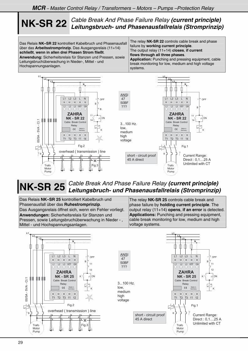
MCR – Master Control Relay / Transformers – Motors – Pumps –Protection Relay
NK-SR 22 Cable Break And Phase Failure Relay (current principle) Leitungsbruch- und Phasenausfallrelais (Stromprinzip)
Das Relais NK–SR 22 kontrolliert Kabelbruch und Phasenausfall über das Arbeitsstromprinzip. Das Ausgangsrelais (11+14) schließt, wenn in allen drei Phasen Strom fließt. Anwendung: Sicherheitsrelais für Stanzen und Pressen, sowie Leitungsbruchüberwachung in Nieder-, Mittel - und Hochspannungsanlagen.
The relay NK-SR 22 controls cable break and phase failure by working current principle. The output relay (11+14) closes, if current flows through all three phases. Application: Punching and pressing equipment, cable break monitoring for low, medium and high voltage systems.
� �
� �
� �
�
� � � � � � � � � � � �
� � � � � � � � � � � � � � � � � � �
� � � � � � � � � � � � � �
�
� �
� �
� �
�
�
� � �
�
� � �
�� ���!��"��!�����
�
# � � � � � � � $ % �
� & � �
� � � � � �
� � �
' & � � � � �
� � �
� � �
7 � � �
� � � �
& ' � � � � � � ( � � � � ) � ) ) & � � * � � � �
� � # � � �
7 � � �
� � � �
) � & � � � ! � � � � � � � + � & & , �
- � � � � � � � � �
. � . # � � � � /
. � . # .. � /
. �
� � � # � �� � � -
0 � � � �
1 � � � � 2
� � � �
� � � � � � �
� 3 � � � � � � � 4 � � & � � � & �
� � � 2
. � . # � � � � /
. � . # .. � /
. �
� � � # � �� � � -
0 � � � �
1 � � � � 2
� � � �
� � � � � � �
� 3 � � � � � � � 4 � � & � � � & �
� � � 2
� /
5
� �
� � �
�
� �
� -
� /
5
� -
% # 4 �
� . ,
8 * 6 9
� 5 5 5
NK-SR 25 Cable Break And Phase Failure Relay (current principle) Leitungsbruch- und Phasenausfallrelais (Stromprinzip)
Das Relais NK–SR 25 kontrolliert Kabelbruch und Phasenausfall über das Ruhestromprinzip. Das Ausgangsrelais öffnet sich, wenn ein Fehler vorliegt. Anwendungen: Sicherheitsrelais für Stanzen und Pressen, sowie Leitungsbruchüberwachung in Nieder - , Mittel - und Hochspannungsanlagen.
The relay NK-SR 25 controls cable break and phase failure by holding current principle. The output relay (11+14) opens, if an error is detected.Applications: Punching and pressing equipment, cable break monitoring for low, medium and high voltage systems.
� �
� �
� �
�
� � � � � � � � � � � �
� � � � � � � � � � � � � � � � � � �
� � � � � � � � � � � � � �
�
� �
� �
� �
�
�
� � �
�
� � �
�� ���!��"��!�����
� �
� �
# � � � � � � � $ % �
� & � �
� � � � � �
� � �
' & � � � � �
� � �
� � �
7 � � �
� � � �
& ' � � � � � � ( � � � � ) � ) ) & � � * � � � �
� � # � � �
7 � � �
� � � �
) � & � � � ! � � � � � � � + � & & , �
- � � � � � � � � �
. � . # � � � � /
. � . # .. � /
. �
� � � # � �� � � �
0 � � � �
1 � � � � 2
� � � �
� � � � � � �
� 3 � � � � � � � 4 � � & � � � & �
� � � 2
. � . # � � � � /
. � . # .. � /
. �
� � � # � �� � � �
0 � � � �
1 � � � � 2
� � � �
� � � � � � �
� 3 � � � � � � � 4 � � & � � � & �
� � � 2
� /
5
5
� � �
�
� �
� �
� /
5
5
% # 4 �
� . ,
8 * 6 9
� 5 5 5
29
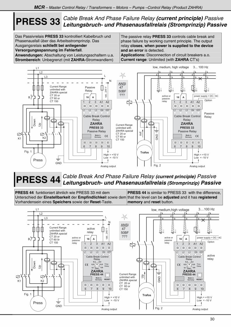
MCR – Master Control Relay / Transformers – Motors – Pumps –Control Relay (Product ZAHRA)
PRESS 33 Cable Break And Phase Failure Relay (current principle) Passive Leitungsbruch- und Phasenausfallrelais (Stromprinzip) Passive
Das Passivrelais PRESS 33 kontrolliert Kabelbruch und Phasenausfall über das Arbeitsstromprinzip. Das Ausgangsrelais schließt bei anliegender Versorgungsspannung im Fehlerfall. Anwendungen: Abschaltung von Leistungsschaltern u.a. Strombereich: Unbegrenzt (mit ZAHRA-Stromwandlern)
The passive relay PRESS 33 controls cable break and phase failure by working current principle. The output relay closes, when power is supplied to the device and an error is detected. Applications: Disconnection of circuit breakers a.o. Current range: Unlimited (with ZAHRA CT’s)
! � � � � � 3 � � � �
� � � � � � � � � � � � � �
G % 0 3 % � � � � � � �
! � � � * � �
! � � / * � �
! � � ( 8 *
& (
& �
& )
6
@ (@ �
: # �
� � � � � � $
����
��
(;8+++�.8�$
&
#
9 � � + � (
% # 4 �
� . ,
8 * 6 9
� 5 5 5
0 � � � � B � � ( * � $
& � � � � B � - ( * � $
� 1 � � 3 �
! � � � � � 3 � � � �
� � � � � � � � � � � � � �
G % 0 3 % � � � � � � �
! � � � * � �
! � � / * � �
! � � ( 8 * :#�
� � � � � � $
���
� � � � �
3 � � �
0 � � � � B � � ( * � $
& � � � � B � - ( * � $
% � � � � � � � � � � � % � � � � � � � � � � �9 � � + � �
� � � � � � � � � � � � B � � ! � ? � % !
' � � � � �
� � � � � �
� � � � �
� � �
� � � �
/ , ; < ( *
( ) % ( % �
& ( ' 9 9& )
, $ � � $
% � B � � 4 �
� � 1 . � 4 �
& � ' #
�
� � ! � � � � �
! " � � � 6 � � ! � � � � �
� 3 � � � �
� � � � � � 3 � � �
� � � = � � � � � � � = � � � � � � � � � � � � � � � � ) + + + � ( * * � 0 1
/ , ; < ( *
( ) % ( % �
& ( ' 9 9& )
, $ � � $
% � B � � 4 �
� � 1 . � 4 �
& � ' #
�
� � ! � � � � �
! " � � � 6 � � ! � � � � �
� 3 � � � �
� � � � � � 3 � � �
� � � � � �
3 � � �
PRESS 44 Cable Break And Phase Failure Relay (current principle) Passive Leitungsbruch- und Phasenausfallrelais (Stromprinzip) Passive
PRESS 44 funktioniert ähnlich wie PRESS 33 mit dem Unterschied der Einstellbarkeit der Empfindlichkeit sowie dem Vorhandensein eines Speichers sowie der Reset-Taste.
PRESS 44 is similar to PRESS 33 with the difference, that the level can be adjusted and it has registered memory and reset button.
� � � � = � � � � � � � = � � � � � � � � � � �
! � � � � � 3 � � � �
� � � � � � � � � � � � � �
G % 0 3 % � � � � � � �
! � � � * � �
! � � / * � *
! � � ( 8 *
& (
& �
& )
6
@ ( @ �
: # �
� � � � � � $
����
��
(;8+++�.8�$
&
#
9 � � + � (
� � � �
� � �
0 � � � � B � � ( * � $
& � � � � B � - ( * � $
� 1 � � 3 �
! � � � � � 3 � � � �
� � � � � � � � � � � � � �
G % 0 3 % � � � � � � �
! � � � � * � �
! � � � / * � �
! � � ( 8 *
:#�
� � � � � � $
��
� � � �
� � �
0 � � � � B � � ( * � $
& � � � � B � - ( * � $
% � � � � � � � � � � � % � � � � � � � � � � �9 � � + � �
) + + + + ( * * � 0 1
� � � � � � � � � � � � B � � ! � ? � % !
' � � � � �
� � � � � �
� � � � �
� � �
� � � � � �
� � � � �
� � �
� � � �
/ , ; < ( *
( ) % ( % �
& ( ' 9 9& )
4 � � +
, $ � � $
% � B � � 4 �
� � 1 . � 4 �
� 0 �
& � ' #
�
� 0 �� 0 �
� 0 �
� 0 � � 0
� � � �
� � � �
� � ! � � � � �
� ! � ! �
! " � � � 6 � � ! � � � � �
3 � � � �
/ , ; < ( *
( ) % ( % �
& ( ' 9 9& )
4 � � +
, $ � � $
% � B � � 4 �
� � 1 . � 4 �
� 0 �
& � ' #
�
� 0 �� 0 �
� 0 �
� 0 � � 0
� � � �
� � � �
� � ! � � � � �
� ! � ! �
! " � � � 6 � � ! � � � � �
3 � � � �
% # 4 �
� . ,
8 * 6 9
� 5 5 5
30
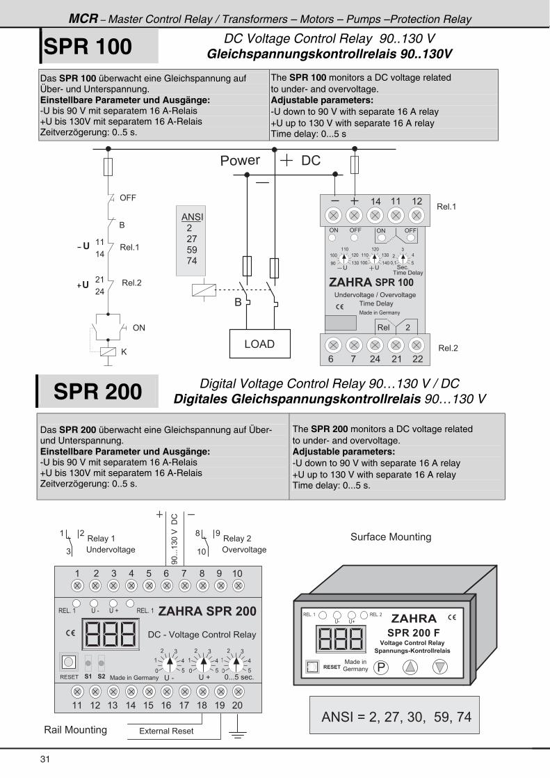
MCR – Master Control Relay / Transformers – Motors – Pumps –Protection Relay
SPR 100 DC Voltage Control Relay 90..130 V Gleichspannungskontrollrelais 90..130V
Das SPR 100 überwacht eine Gleichspannung auf Über- und Unterspannung. Einstellbare Parameter und Ausgänge: -U bis 90 V mit separatem 16 A-Relais +U bis 130V mit separatem 16 A-Relais Zeitverzögerung: 0..5 s.
The SPR 100 monitors a DC voltage related to under- and overvoltage. Adjustable parameters: -U down to 90 V with separate 16 A relay +U up to 130 V with separate 16 A relay Time delay: 0...5 s
' #
� � � �
' # ' 9 9 ' 9 9' #
( . ( ( ( �
4 � � +��
, $ � � $
� � � � � � � � � � ? � ' � � � � � �
� � � � � � �
( * *
( ( *
( � *
( ) *< *
( ( *
( � *
( ) *
( . *( * *
�
)
.
8* = (
7 � � � � � � : � � � �
' 9 9
6
( .
( (
@
� .
� (
� � � � � � � � �
� � � � � � � � �
3 � � + ( �
3 � � + � �
� . � ( � �
& ' % �
6
'
'
/ ,
3 � � � � � � � � � �
� !
3 � � + ( �
3 � � + � �
% # 4 �
� � �
� � � ,
� � 8 <
� � , .
SPR 200 Digital Voltage Control Relay 90…130 V / DC Digitales Gleichspannungskontrollrelais 90…130 V
Das SPR 200 überwacht eine Gleichspannung auf Über- und Unterspannung. Einstellbare Parameter und Ausgänge: -U bis 90 V mit separatem 16 A-Relais +U bis 130V mit separatem 16 A-Relais Zeitverzögerung: 0..5 s.
The SPR 200 monitors a DC voltage related to under- and overvoltage. Adjustable parameters: -U down to 90 V with separate 16 A relay +U up to 130 V with separate 16 A relay Time delay: 0...5 s.
3 � � � � (
( �
) � � � � � � � � �
<*+++()*�$���!
7 � � � � � �
: � � � �
, $ � � $
� � � � � � � � �
� ! � ! �
� 3 � 6 � = � � � 3 4 6 1 3 � � � � � � �
� � � 4 4 8 4 = � & * 3 4 6 1 3 � � 1 � � � �
3 � & + � �3 � & + � (
� - � �
�
� � � � � � � 3 � � � �3 � � � 7 � � � � � � �
4 � � � � � 7 � � � � � � �3 � � � � �
; <
( *' � � � � � �
( � ) . 8 / , ; < ( *
( ( ( � ( ) ( . ( 8 ( / ( , ( ; ( < � *
3 � 4 � �
, $ � � $ � � � � � � � �
� � -
� ! � - � $ � � � � � � ! � � � � � � 3 � � �
* 8
(
� )
.
* + + + 8 � � � � +� � �
* 8
(
� )
.
* 8
(
� )
.
� � � �
3 � & + � ( 3 � & + � (� � - � � �
7 � � � � � � : � � � �
% # 4 � � B � � = � � , = � ) * = � � 8 < = � , . � �
31
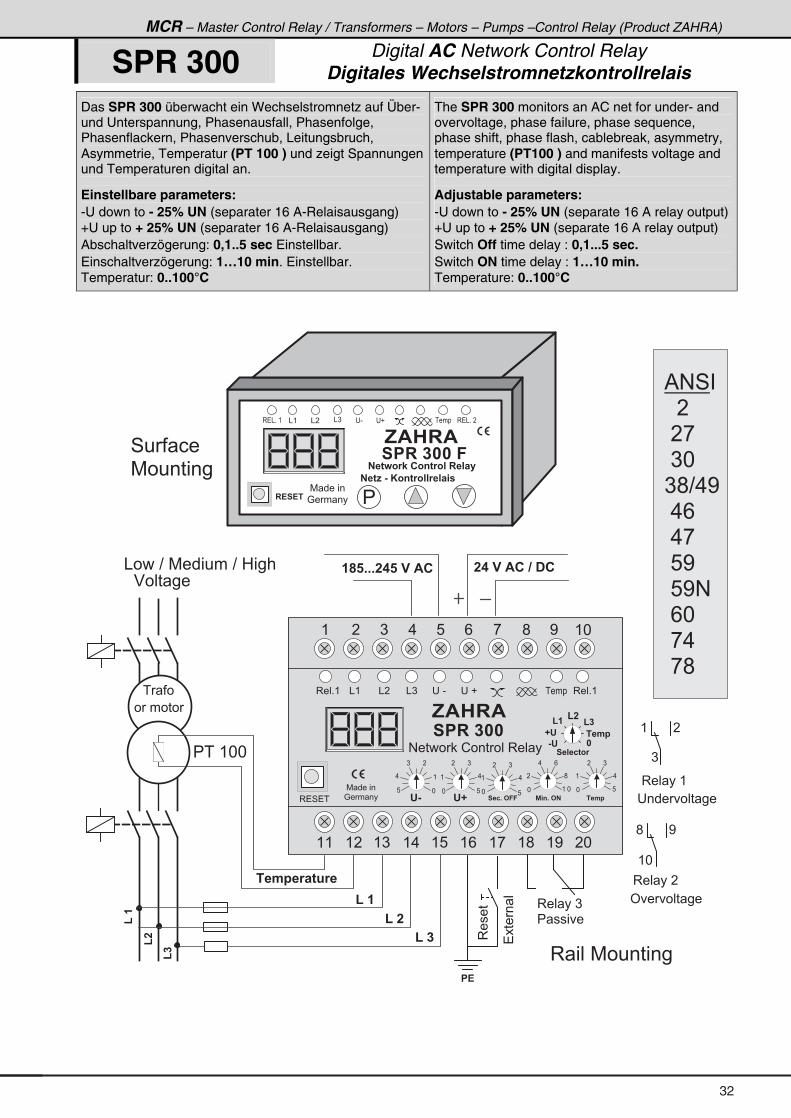
MCR – Master Control Relay / Transformers – Motors – Pumps –Control Relay (Product ZAHRA)
SPR 300 Digital AC Network Control Relay Digitales Wechselstromnetzkontrollrelais
Das SPR 300 überwacht ein Wechselstromnetz auf Über- und Unterspannung, Phasenausfall, Phasenfolge, Phasenflackern, Phasenverschub, Leitungsbruch, Asymmetrie, Temperatur (PT 100 ) und zeigt Spannungen und Temperaturen digital an.
Einstellbare parameters: -U down to - 25% UN (separater 16 A-Relaisausgang) +U up to + 25% UN (separater 16 A-Relaisausgang) Abschaltverzögerung: 0,1..5 sec Einstellbar. Einschaltverzögerung: 1…10 min. Einstellbar. Temperatur: 0..100°C
The SPR 300 monitors an AC net for under- and overvoltage, phase failure, phase sequence, phase shift, phase flash, cablebreak, asymmetry, temperature (PT100 ) and manifests voltage and temperature with digital display.
Adjustable parameters: -U down to - 25% UN (separate 16 A relay output)+U up to + 25% UN (separate 16 A relay output) Switch Off time delay : 0,1...5 sec. Switch ON time delay : 1…10 min. Temperature: 0..100°C
(��
( � �
( � �
( � �
(�
(�
7 � � � � � �
: � � � �
, $ � � $
� � � � � � � � �
� ! � ! �
� � 6 : 3 1 < � � 3 4 6 1 3 � � � � � � �
� � 6 E � & � * 3 4 6 1 3 � � 1 � � � �
& ( & � & ) � - � �
�
� !
� � + + + � � � � � � $ �
3 � & + � (
� � � � � $ � � � � �
����� ��
� � . � � 1 � 6 8 1 �
� � � � 3 � & + � �
3 � � � 7 � � � � � � �
4 � � � �
7 � � � � � � �
� � �
& � � � ? � 7 � � � � � � ? � 0 � � �
$ � � � � �
� � � � � �
� � � ( * *
3 � � � � (
( �
)
� � � � � � � � �
3 � � � � �
; <
( *
' � � � � � �
�3���� 3 � � � � )
� � � � � �
( � ) . 8 / , ; < ( *
( ( ( � ( ) ( . ( 8 ( / ( , ( ; ( < � *
& ( & � & ) � � - � � �3 � � + ( 3 � � + (� � � �
7 � � � � �
: � � � �3 � 4 � � ' &
8 *
. (
) �
' D
* 8
( .
� )
* 8
( .
� )
� � 2 + � # � �
* ( *
� ;
. /
% 4 + � # �
* 8
( .
� )
� � . �
, $ � � $
� � � � � � �
( �( �( �
� � � � 2 6 3 1
& '
D ' � � . �
�
# � � � � � ! � � � � � � 3 � � �
% # 4 �
� � � �
� � ,
� ) *
) ; ? . <
� . /
� . ,
� 8 <
� 8 < #
� / *
� , .
� , ;
32
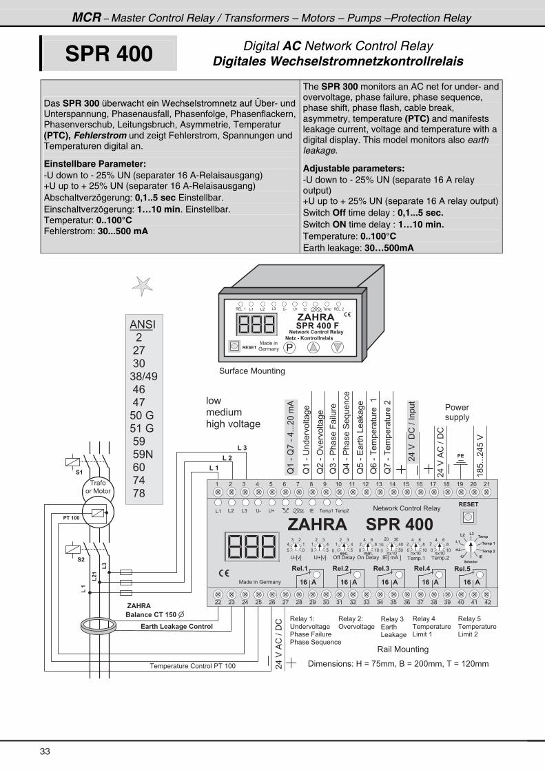
MCR – Master Control Relay / Transformers – Motors – Pumps –Protection Relay
SPR 400 Digital AC Network Control Relay Digitales Wechselstromnetzkontrollrelais
Das SPR 300 überwacht ein Wechselstromnetz auf Über- und Unterspannung, Phasenausfall, Phasenfolge, Phasenflackern, Phasenverschub, Leitungsbruch, Asymmetrie, Temperatur (PTC), Fehlerstrom und zeigt Fehlerstrom, Spannungen und Temperaturen digital an.
Einstellbare Parameter: -U down to - 25% UN (separater 16 A-Relaisausgang) +U up to + 25% UN (separater 16 A-Relaisausgang) Abschaltverzögerung: 0,1..5 sec Einstellbar. Einschaltverzögerung: 1…10 min. Einstellbar. Temperatur: 0..100°C Fehlerstrom: 30...500 mA
The SPR 300 monitors an AC net for under- and overvoltage, phase failure, phase sequence, phase shift, phase flash, cable break, asymmetry, temperature (PTC) and manifests leakage current, voltage and temperature with a digital display. This model monitors also earth leakage.
Adjustable parameters: -U down to - 25% UN (separate 16 A relay output) +U up to + 25% UN (separate 16 A relay output)Switch Off time delay : 0,1...5 sec. Switch ON time delay : 1…10 min. Temperature: 0..100°C Earth leakage: 30…500mA
(��
( � �
( � �
( � �
� �
� � � � � � � � � ! � � � � � � � � � ( * *
! � 1 6 ; � ( � � < � = � � � 3 4 6 1 3 �
� �
(��
(�
� � �
, $ � � $
� � � � 4 2 � � � � � � � �
� � � � � �
� !
3 � � � � ( 2
� � � � � � � � �
� � � � � 9 � � � �
� � � � � 4 � � � � � � �
3 � � � � � 2
' � � � � � �
3 � � � � )
� � � �
& � � �
3 � � � � .
� � � � � � � �
& � � � � � (
3 � � � � 8
� � � � � � � �
& � � � � � �
3 � � � 7 � � � � � � �
( � ) . 8 / , ; < ( * ( ( ( � ( ) ( . ( 8 ( / ( , ( ; ( < � * � (
� � � ) � . � 8 � / � , � ; � < ) * ) ( ) � ) ) ) . ) 8 ) / ) , ) ; ) < . * . ( . �
� ! � ! �
, $ � � $ � � � � � � �
� - E F � � E F ' � � � � � � � � E � � % � F � � � � + (
� � � � � � � � � � 2 � 0 � B � , 8 � � = � 6 � B � � * * � � = � � � B � ( � * � �
8 *
. (
) �
* 8
( .
� )
* ( *
� ;
. /
) 8 *
( * . *
� * ) *
* ( *
� ;
. /
� � � + � � � � + �
� $ � $
� � � + �
� $
� � � + �
� $
� � � + �
� $
& � & ) � - � �& ( � � � � � � ( � � � � �
(;8+++�.8�$
�.�$�%!�?��!
. 4 +
* ( *
� ;
. /
# � � � � � ! � � � � � � 3 � � �
( �
( �
( �
� � � � 2 6 3 1
& '
D '
� � . �
� � . � � �
� � . � � �
" !
4 � � � � � 7 � � � � � � �
N(�-�������� ��
N��-�'���� ��
N)�-��� ���9 ����
N.�-��� ���4�������
N8�-�� ���&� ���
N/�-������ �����(
N,�-������ �����
� � 7 � � �
� � � �
� � � � � � �
� � � � � � � � � �
�.�$�%!�?��!
� � � � + �
� � � �
� � � � � �
�.�$���!�?������
N(�-�N,�-�.+++�*��%
7 � � � � � � : � � � �
7 � � � � � �
: � � � �
, $ � � $
� � � � � � � � �
� ! � ! �
� � 6 : 3 1 < � � 3 4 6 1 3 � � � � � � �
� � 6 E � & � * 3 4 6 1 3 � � 1 � � � �
& ( & � & ) � - � �
�
3 � & + � ( � � � � 3 � & + � �
� � ( * � � ( * � � ( *
' � � � � � � �
* = ( 8
( .
� )
� � 2 +
% # 4 �
� � � �
� � ,
� ) *
) ; ? . <
� . /
� . , �
8 * � :
8 ( � :
� 8 <
� 8 < #
� / *
� , .
� , ;
33
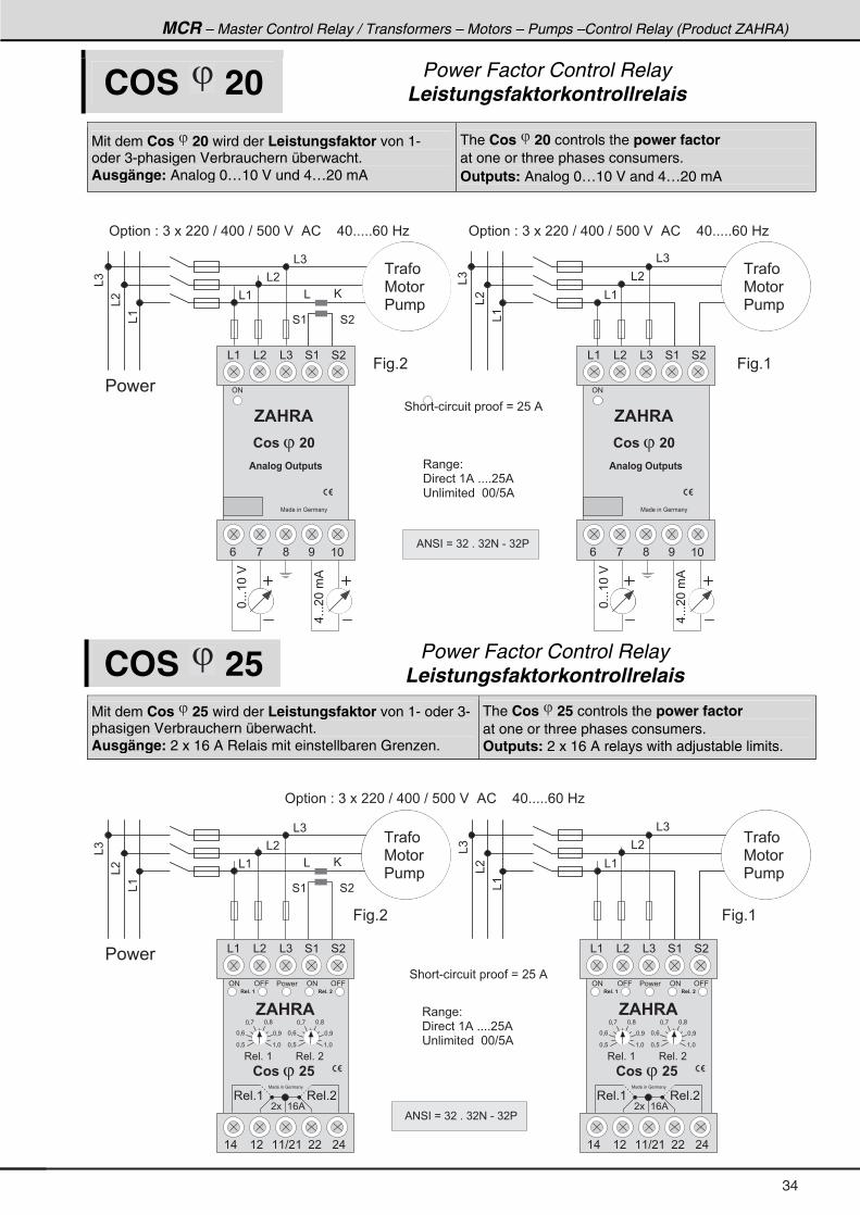
MCR – Master Control Relay / Transformers – Motors – Pumps –Control Relay (Product ZAHRA)
COS 20 Power Factor Control Relay Leistungsfaktorkontrollrelais
Mit dem Cos 20 wird der Leistungsfaktor von 1- oder 3-phasigen Verbrauchern überwacht. Ausgänge: Analog 0…10 V und 4…20 mA
The Cos 20 controls the power factor at one or three phases consumers. Outputs: Analog 0…10 V and 4…20 mA
& @
& )
& �
& (
� � � �
4 ( 4 �
& )
& �
& (
&(
&�
&)
&(
&�
&)
' � � � � � � 2 � ) � � � � � * � ? � . * * � ? � 8 * * � $ � � % ! � � � � . * + + + + + / * � 0 1
� � �
7 � � �
� � � �
� � �
7 � � �
� � � �
' � � � � � � 2 � ) � � � � � * � ? � . * * � ? � 8 * * � $ � � % ! � � � � . * + + + + + / * � 0 1
3 � � � 2
� � � � � � ( % � + + + + � 8 %
� � � � � � � � � � � * * ? 8 %
*+++(*�$
.+++�*��%
4 � � � - � � � � � � � � � � � � B � � 8 � %
*+++(*�$
.+++�*��%
9 � � + �
' #
& ( & � & ) 4 ( 4 �
, $ � � $
/ , ; < ( *
7 � � � � � � : � � � �
$ 4 � � 3 = � # 8 6 � 8 6 �
� 3 � � � � � � � � �
' #
& ( & � & ) 4 ( 4 �
, $ � � $
/ , ; < ( *
7 � � � � � � : � � � �
$ 4 � � 3 = � # 8 6 � 8 6 �
� 3 � � � � � � � � �
9 � � + (
% # 4 � � B � ) � � + � ) � # � - � ) � �
COS 25 Power Factor Control Relay Leistungsfaktorkontrollrelais
Mit dem Cos 25 wird der Leistungsfaktor von 1- oder 3-phasigen Verbrauchern überwacht. Ausgänge: 2 x 16 A Relais mit einstellbaren Grenzen.
The Cos 25 controls the power factor at one or three phases consumers. Outputs: 2 x 16 A relays with adjustable limits.
& @
& )
& �
& (
� � � �
4 ( 4 �
& )
& �
& (
9 � � + �
&(
&�
&)
&(
&�
&)
' � � � � � � 2 � ) � � � � � * � ? � . * * � ? � 8 * * � $ � � % ! � � � � . * + + + + + / * � 0 1
� � �
7 � � �
� � � �
� � �
7 � � �
� � � �
3 � � � 2
� � � � � � ( % � + + + + � 8 %
� � � � � � � � � � � * * ? 8 %
4 � � � - � � � � � � � � � � � � B � � 8 � %
' # ' 9 9 ' 9 9' #
& ( & � & ) 4 ( 4 �
, $ � � $
� � � + � �� � � + � �
3 � � + � (
* = 8 ( = *
* = <
* = ;* = ,
* = /
3 � � + � �
* = 8 ( = *
* = <
* = ;* = ,
* = /
( . ( � ( ( ? � ( � � � .
3 � � + ( 3 � � + �
7 � � � � � � : � � � �
� � � � ( / %
� � � �
� 3 � � � � � � � � �
' # ' 9 9 ' 9 9' #
& ( & � & ) 4 ( 4 �
, $ � � $
� � � + � �� � � + � �
3 � � + � (
* = 8 ( = *
* = <
* = ;* = ,
* = /
3 � � + � �
* = 8 ( = *
* = <
* = ;* = ,
* = /
( . ( � ( ( ? � ( � � � .
3 � � + ( 3 � � + �
7 � � � � � � : � � � �
� � � � ( / %
� � � �
� 3 � � � � � � � � �
9 � � + (
% # 4 � � B � ) � � + � ) � # � - � ) � �
34
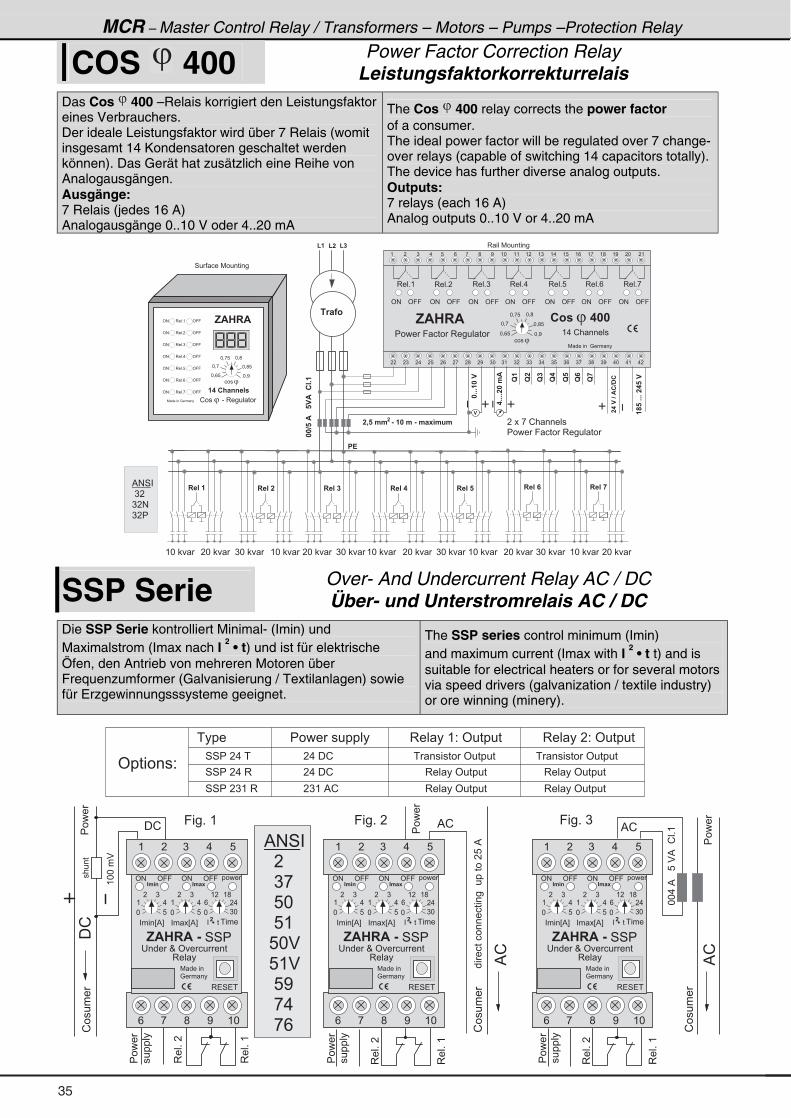
MCR – Master Control Relay / Transformers – Motors – Pumps –Protection Relay
COS 400 Power Factor Correction Relay
Leistungsfaktorkorrekturrelais
Das Cos 400 –Relais korrigiert den Leistungsfaktor eines Verbrauchers. Der ideale Leistungsfaktor wird über 7 Relais (womit insgesamt 14 Kondensatoren geschaltet werden können). Das Gerät hat zusätzlich eine Reihe von Analogausgängen. Ausgänge: 7 Relais (jedes 16 A) Analogausgänge 0..10 V oder 4..20 mA
The Cos 400 relay corrects the power factor of a consumer. The ideal power factor will be regulated over 7 change-over relays (capable of switching 14 capacitors totally). The device has further diverse analog outputs. Outputs: 7 relays (each 16 A) Analog outputs 0..10 V or 4..20 mA
( � ) . 8 / , ; < ( * ( ( ( � ( ) ( . ( 8 ( / ( , ( ; ( < � * � (
� � � ) � . � 8 � / � , � ; � < ) * ) ( ) � ) ) ) . ) 8 ) / ) , ) ; ) < . * . ( . �
� 0 � � . . � � & � � � � . � & � . � - . 8 .
( � ( � ( �
������$���
���+++�������
����$�����$����+�
3 � � + ( 3 � � + � 3 � � + ) 3 � � + . 3 � � + 8 3 � � + / 3 � � + ,
' # ' 9 9 ' # ' 9 9 ' # ' 9 9 ' # ' 9 9 ' # ' 9 9 ' # ' 9 9 ' # ' 9 9
� !
� � � � � � � � � �� � � � � � � � �� � � � �� � � � �� � � � �
� 1 � � 3
� � � � , � ! � � � � � �
� � � � � 9 � � � � 3 � � � � � � �
( * � � * � ) * � ( * � � * � ) * � ( * � � * � ) * � � � ( * � ) * � ( * � � * �
� � � � � 9 � � � � 3 � � � � � �
�
7 � � � � � � � : � � � �
* = / 8 * = <
* = ; 8
* = ;* = , 8
* = ,
� 3 � � � � � � � � � ��
� � � �
F�
F
F�
F�
F�
F�
F�
� * �
7 � � � � � � : � � � �
' # ' 9 93 � � + (
' # ' 9 93 � � + �
' # ' 9 93 � � + )
' # ' 9 93 � � + .
' # ' 9 93 � � + 8
' # ' 9 93 � � + /
' # ' 9 93 � � + ,
, $ � � $
* = / 8 * = <
* = ; 8
* = ;* = , 8
* = ,
� � � �
! � � � � � � � - � 3 � � � � � � �
� � � � ; � 4 4 � � �
( . � ! � � � � � �
, $ � � $
3 � � � 7 � � � � � � �
4 � � � � � 7 � � � � � � �
�+++����
�++++���.$
�
% # 4 �
� ) �
) � #
) � �
SSP Serie Over- And Undercurrent Relay AC / DC Über- und Unterstromrelais AC / DC
Die SSP Serie kontrolliert Minimal- (Imin) und Maximalstrom (Imax nach I
2 • t) und ist für elektrische
Öfen, den Antrieb von mehreren Motoren über Frequenzumformer (Galvanisierung / Textilanlagen) sowie für Erzgewinnungsssysteme geeignet.
The SSP series control minimum (Imin) and maximum current (Imax with I
2 • t t) and is
suitable for electrical heaters or for several motors via speed drivers (galvanization / textile industry) or ore winning (minery).
%!
�������������������������8�%
�!
9 � � + � (
�����
����
3��+�(
3��+��
3��+�(
3��+��
**.�%���8�$%��!�+(
!�����
(**��$
� � � � � � � � � � � � � � � � � 3 � � � � ( 2 � ' � � � � � � 3 � � � � � 2 � ' � � � � � �
' � � � � � � 2
!�����
� ! % !
����
������
3��+�(
3��+��
% !
!�����
9 � � + � � 9 � � + � )
����
����
����
������
����
������
4 4 � � � . � �
4 4 � � � . � 3
4 4 � � � ) ( � 3
� � . � � !
� � . � � !
� � ) ( � % ! � 3 � � � � ' � � � � �
� 3 � � � � ' � � � � �
� � � � � � � � � ' � � � � �
� 3 � � � � ' � � � � �
� 3 � � � � ' � � � � �
� � � � � � � � � ' � � � � �
%!
% # 4 �
� � �
� � ) ,
� � 8 *
� � 8 (
� 8 * $
� 8 ( $
� � 8 <
� � , .
� � , /
( � ) . 8
' 9 9' #
, $ � � $ � & � 4 4 �
� � � � � O � ' � � � � � � �
3 � � �
' 9 9' # � � � �
" . 4 " . � -
/ ; < ( *,
3 � 4 � �
7 � � � � �
: � � � �
* ) *
/ � .
( � ( ;
* 8
( .
� )
* 8
( .
� )
� � � � �� � � � � ��
� � � � E % F � � � E % F
( � ) . 8
' 9 9' #
, $ � � $ � & � 4 4 �
� � � � � O � ' � � � � � � �
3 � � �
' 9 9' # � � � �
" . 4 " . � -
/ ; < ( *,
3 � 4 � �
7 � � � � �
: � � � �
* ) *
/ � .
( � ( ;
* 8
( .
� )
* 8
( .
� )
� � � � �� � � � � ��
� � � � E % F � � � E % F
( � ) . 8
' 9 9' #
, $ � � $ � & � 4 4 �
� � � � � O � ' � � � � � � �
3 � � �
' 9 9' # � � � �
" . 4 " . � -
/ ; < ( *,
3 � 4 � �
7 � � � � �
: � � � �
* ) *
/ � .
( � ( ;
* 8
( .
� )
* 8
( .
� )
� � � � �� � � � � ��
� � � � E % F � � � E % F
35
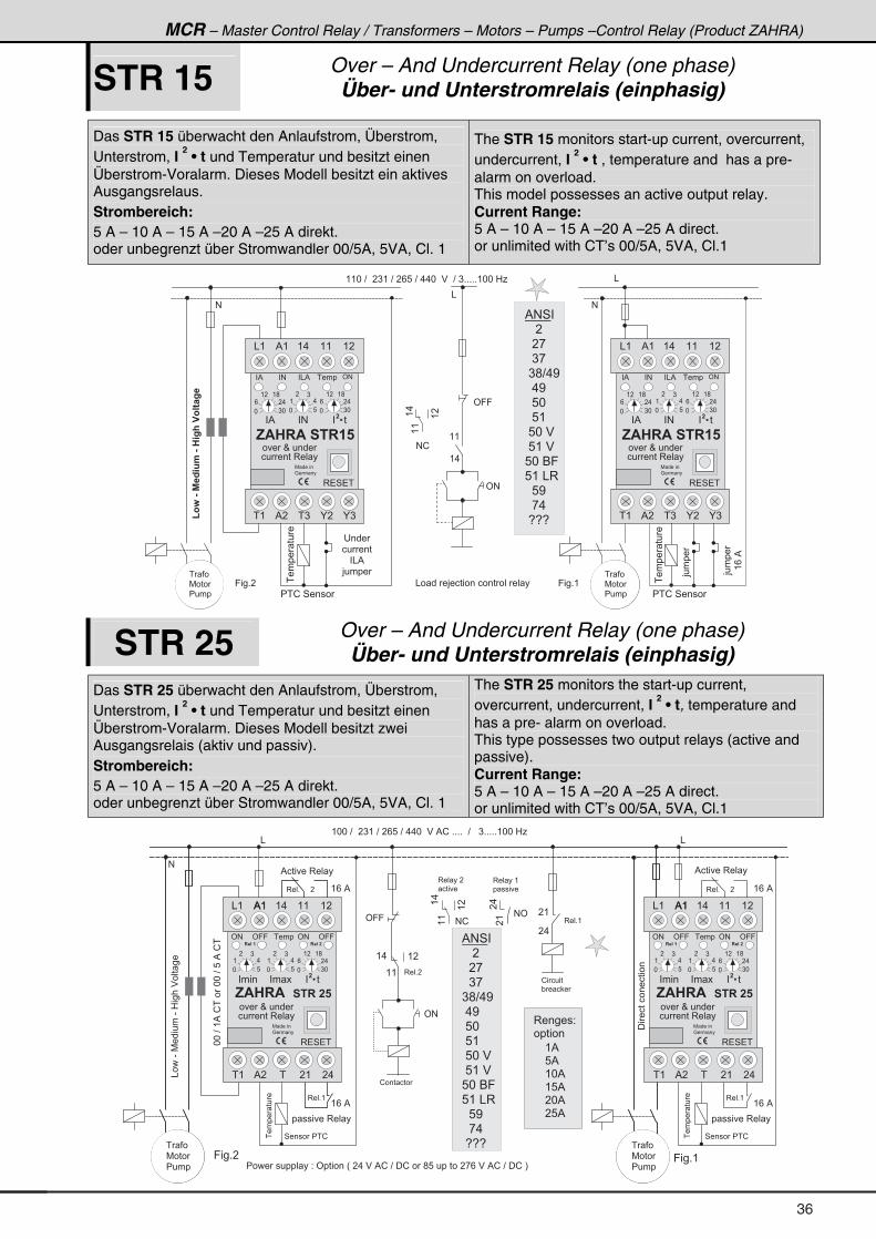
MCR – Master Control Relay / Transformers – Motors – Pumps –Control Relay (Product ZAHRA)
STR 15 Over – And Undercurrent Relay (one phase) Über- und Unterstromrelais (einphasig)
Das STR 15 überwacht den Anlaufstrom, Überstrom, Unterstrom, I
2 • t und Temperatur und besitzt einen
Überstrom-Voralarm. Dieses Modell besitzt ein aktives Ausgangsrelaus. Strombereich: 5 A – 10 A – 15 A –20 A –25 A direkt. oder unbegrenzt über Stromwandler 00/5A, 5VA, Cl. 1
The STR 15 monitors start-up current, overcurrent, undercurrent, I
2 • t , temperature and has a pre-
alarm on overload. This model possesses an active output relay. Current Range: 5 A – 10 A – 15 A –20 A –25 A direct. or unlimited with CT’s 00/5A, 5VA, Cl.1
#
9 � � + �
' 9 9
( (
( .
' #
&����� ���
� � � �
� � � � �
� & %
> � � � �
( ( * � ? � � � ) ( � ? � � / 8 � ? � . . * � � $ � � ? � ) + + + + + ( * * � 0 1
>����
� � ! � 4 � � � �
>����
(/�%
����� ���
((
(.
(�
& � � � � > � � � � � � � � � � � � � � � � �
# !
(3:�&�%�B 8.�&�� =;��3�6�=�
� � �
7 � � �
� � � �
9 � � + (
� � �
7 � � �
� � � �
% # 4 �
� � � �
� � � ,
� � ) ,
� ) ; ? . <
� � . <
� � 8 *
� � 8 (
� 8 * � $
� 8 ( � $
8 * � 6 9
8 ( � & 3
� � 8 <
� � , .
� 5 5 5
& ( % ( ( . ( ( ( �
� #� %
, $ � � $ � � � � � �
� � � O � � � � �
� � � � � � 3 � � �
� % � � � � ��
� � � �� & % ' #
� ( � ) K � K )% �
3 � 4 � �
� #
7 � � � � �
: � � � �
* ) *
/ � .
( � ( ;
* ) *
/ � .
( � ( ;
* 8
( .
� )
& ( % ( ( . ( ( ( �
� #� %
, $ � � $ � � � � � �
� � � O � � � � �
� � � � � � 3 � � �
� % � � � � ��
� � � �� & % ' #
� ( � ) K � K )% �
3 � 4 � �
� #
7 � � � � �
: � � � �
* ) *
/ � .
( � ( ;
* ) *
/ � .
( � ( ;
* 8
( .
� )
&
#
� � ! � 4 � � � �
STR 25 Over – And Undercurrent Relay (one phase) Über- und Unterstromrelais (einphasig)
Das STR 25 überwacht den Anlaufstrom, Überstrom, Unterstrom, I
2 • t und Temperatur und besitzt einen
Überstrom-Voralarm. Dieses Modell besitzt zwei Ausgangsrelais (aktiv und passiv). Strombereich: 5 A – 10 A – 15 A –20 A –25 A direkt. oder unbegrenzt über Stromwandler 00/5A, 5VA, Cl. 1
The STR 25 monitors the start-up current, overcurrent, undercurrent, I
2 • t, temperature and
has a pre- alarm on overload. This type possesses two output relays (active and passive). Current Range: 5 A – 10 A – 15 A –20 A –25 A direct. or unlimited with CT’s 00/5A, 5VA, Cl.1
#
' 9 9
' #
&
( * * � ? � � � ) ( � ? � � / 8 � ? � . . * � � $ � % ! � + + + + � � ? � � � ) + + + + + ( * * � 0 1
((
(.
(�
# !
&���-�7������-�0����$��� ��
3 � � + � � � � � �
3 � � � � � 2
� � � � � �
( %
8 %
( * %
( 8 %
� * %
� 8 %
# '
�(
�.
&
����� ���
4 � � � � � � � !
3 � � + � � � � � �
3 � � + (
% � � � � � 3 � � � �
� � � � � � 3 � � �
( (
( . ( �
3 � � � � �
� � � �
3 � � � � (
� � � � �
����� ���
4 � � � � � � � !
9 � � + �
3 � � + (
! � � � � � �
3 � � + (
3 � � + �
! � � � � �
" � � �
� � � � � � 3 � � �
% � � � � � 3 � � � �
( / � %
( / � %
( / � %
( / � %
� � �
7 � � �
� � � �
**�?�(%�!����**�?�8�%�!�
���������������
� � � � � � � � � � � � 2 � ' � � � � � � H � � . � $ � % ! � ? � � ! � � � ; 8 � � � � � � � � , / � $ � % ! � ? � � ! � I
� � �
7 � � �
� � � �
9 � � + (
% ( ( .& ( ( ( ( �
' 9 9' #
, $ � � $ � � � � � � � �
� � � � � � � � ��
� � � �
3 � 4 � �
� � �
7 � � � � �
: � � � �
* ) *
/ � .
( � ( ;
* 8
( .
� )
� � � � � � � � � �
* 8
( .
� )
% (
� ( � � ( � .% �
' 9 9' #
� � � O � � � � �
� � � � � � 3 � � �
% ( ( .& ( ( ( ( �
' 9 9' #
, $ � � $ � � � � � � � �
� � � � � � � � ��
� � � �
3 � 4 � �
� � �
7 � � � � �
: � � � �
* ) *
/ � .
( � ( ;
* 8
( .
� )
� � � � � � � � � �
* 8
( .
� )
% (
� ( � � ( � .% �
' 9 9' #
� � � O � � � � �
� � � � � � 3 � � �
� .
� (
% # 4 �
� � � �
� � � ,
� � ) ,
) ; ? . <
� . <
� 8 *
� 8 (
� 8 * � $
� 8 ( � $
8 * � 6 9
8 ( � & 3
� � 8 <
� � , .
� 5 5 5
36
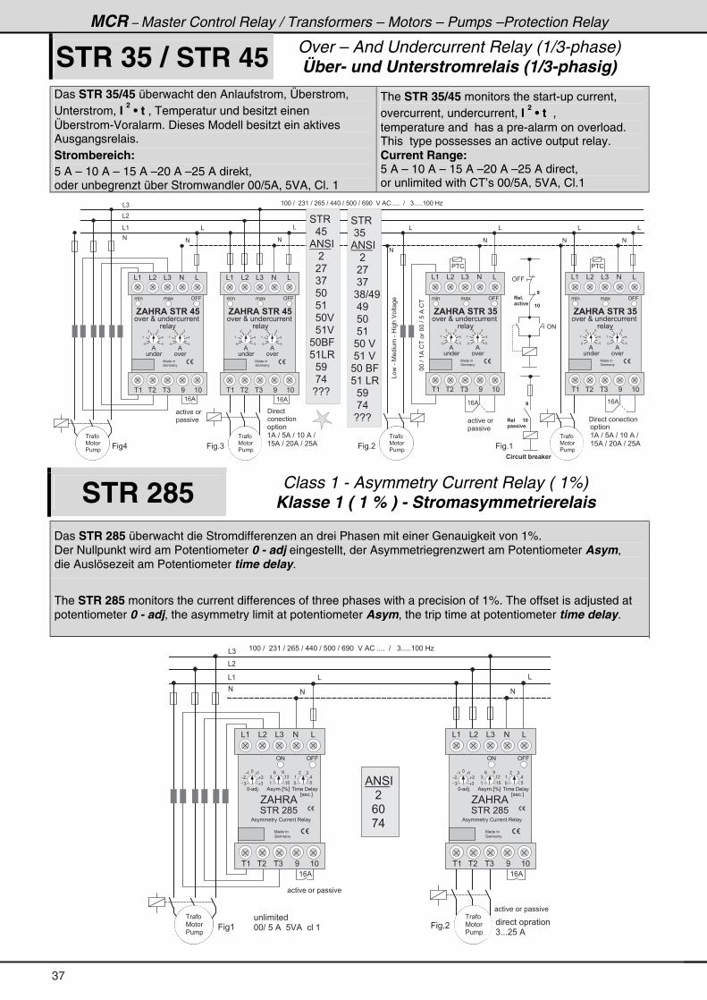
MCR – Master Control Relay / Transformers – Motors – Pumps –Protection Relay
STR 35 / STR 45 Over – And Undercurrent Relay (1/3-phase) Über- und Unterstromrelais (1/3-phasig)
Das STR 35/45 überwacht den Anlaufstrom, Überstrom, Unterstrom, I
2 • t , Temperatur und besitzt einen
Überstrom-Voralarm. Dieses Modell besitzt ein aktives Ausgangsrelais. Strombereich: 5 A – 10 A – 15 A –20 A –25 A direkt, oder unbegrenzt über Stromwandler 00/5A, 5VA, Cl. 1
The STR 35/45 monitors the start-up current, overcurrent, undercurrent, I
2 • t ,
temperature and has a pre-alarm on overload. This type possesses an active output relay. Current Range: 5 A – 10 A – 15 A –20 A –25 A direct, or unlimited with CT’s 00/5A, 5VA, Cl.1
#
' 9 9
' #
( * * � ? � � � ) ( � ? � � / 8 � ? � . . * � ? � 8 * * � ? � / < * � � $ � % ! � + + + + � � ? � � � ) + + + + + ( * * � 0 1
&���-�7������-�0����$��� ��
9 � � + (
#
� � � +
� 2 6 9 �
� 1 2 8 6 � @ 1 � � < � 1
**�?�(%�!����**�?�8�%�!�
� � � � � � � � � � � � � � �
&
�
� �
� � �
� � � � 9 � +
9 � � + �
&
#
&
#
&
#
&
�
� �
9 � � + )
#
&& (
& �
& )
#
9 � � .
� � �
7 � � �
� � � �
� � �
7 � � �
� � � �
� � �
7 � � �
� � � �
� � �
7 � � �
� � � �
� � ! � � !
( / % ( / %( / %( / %
� � � � � �
� � � � � � � � � � � �
� � � � �
& ( # &
, $ � � $ � � � � � � �
� � � �
7 � � � � �
: � � � �
& )& �
� ( � ) < ( *� �
*
(
� )
.
8 *
(
� )
.
8
%
� �
%
� � � ' 9 9� �
� � � O � � � � � � � � � �
� � � �
& ( # &
, $ � � $ � � � � � � �
� � � �
7 � � � � �
: � � � �
& )& �
� ( � ) < ( *� �
*
(
� )
.
8 *
(
� )
.
8
%
� �
%
� � � ' 9 9� �
& ( # &
� � � �
7 � � � � �
: � � � �
)�
� ( ( � ( ( ( .
*
(
� )
.
8 *
(
� )
.
8
$
� �
$
� � � ' 9 9� �
, $ � � $ � � � � � � �
� � � O � � � � � � � � � � �
� � � �
& ( # &
� � � �
7 � � � � �
: � � � �
& )& �
� ( � ) < ( *� �
*
(
� )
.
8 *
(
� )
.
8
%
� �
%
� � � ' 9 9� �
, $ � � $ � � � � � � �
& ( # &
� � � �
7 � � � � �
: � � � �
)�
� ( ( � ( ( ( .
*
(
� )
.
8 *
(
� )
.
8
$
� �
$
� � � ' 9 9� �
, $ � � $ � � � � � � �
� � � O � � � � � � � � � � �
� � � �
& ( # &
� � � �
7 � � � � �
: � � � �
& )& �
� ( � ) < ( *� �
*
(
� )
.
8 *
(
� )
.
8
%
� �
%
� � � ' 9 9� �
, $ � � $ � � � � � � �
� � � O � � � � � � � � � �
� � � �
� � � O � � � � � � � � � �
� � � �
� � � O � � � � � � � � � �
� � � �
� � � � � �
( % � ? � 8 % � ? � ( * � % � ? �
( 8 % � ? � � * % � ? � � 8 %
� � � � � �
� � � � � � � � �
� � � � � �
( % � ? � 8 % � ? � ( * � % � ? �
( 8 % � ? � � * % � ? � � 8 %
4 � 3
� ) 8
% # 4 �
� � � �
� � � ,
� � ) ,
� ) ; ? . <
� � . <
� � 8 *
� � 8 (
� 8 * � $
� 8 ( � $
8 * � 6 9
8 ( � & 3
� � 8 <
� � , .
� 5 5 5
4 � 3
� � . 8
% # 4 �
� � � �
� � � ,
� � ) ,
� � 8 *
� � 8 (
� � 8 * $
� � 8 ( $
8 * 6 9
8 ( & 3
� � 8 <
� � , .
� 5 5 5
STR 285 Class 1 - Asymmetry Current Relay ( 1%) Klasse 1 ( 1 % ) - Stromasymmetrierelais
Das STR 285 überwacht die Stromdifferenzen an drei Phasen mit einer Genauigkeit von 1%. Der Nullpunkt wird am Potentiometer 0 - adj eingestellt, der Asymmetriegrenzwert am Potentiometer Asym, die Auslösezeit am Potentiometer time delay.
The STR 285 monitors the current differences of three phases with a precision of 1%. The offset is adjusted at potentiometer 0 - adj, the asymmetry limit at potentiometer Asym, the trip time at potentiometer time delay.
( * * � ? � � � ) ( � ? � � / 8 � ? � . . * � ? � 8 * * � ? � / < * � � $ � % ! � + + + + � � ? � � � ) + + + + + ( * * � 0 1
#
&
9 � � + �
#
&& (
& �
& )
#
9 � � (
� � �
7 � � �
� � � �
� � �
7 � � �
� � � �
( / %
� � � � � � � � � � � �
% # 4 �
� � � �
� � / *
� � , .
& ( # &
7 � � � � �
: � � � �
& )& �
� ( � ) < ( *� �
' 9 9' #
� � � � � � � � � � � �
� � � � � � � � � � � �
) + + + � 8 � %
� � � � � � � � �
* * ? � 8 � % � � 8 $ % � � � � � (
G % 0 3 %
4 � 3 � � ; 8
* - � > +
) )
� �
( (*
% � � � + E J F � � � � � � � � �
( ( 8
) ( �
/ <
* 8
( .
� )
E � � � + F
% � � � � � � � � ! � � � � � 3 � � �
( / %
& ( # &
7 � � � � �
: � � � �
& )& �
� ( � ) < ( *� �
' 9 9' #
G % 0 3 %
4 � 3 � � ; 8
* - � > +
) )
� �
( (*
% � � � + E J F � � � � � � � � �
( ( 8
) ( �
/ <
* 8
( .
� )
E � � � + F
% � � � � � � � � ! � � � � � 3 � � �
37
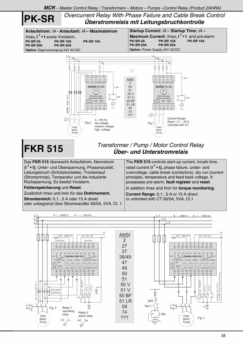
MCR – Master Control Relay / Transformers – Motors – Pumps –Control Relay (Product ZAHRA)
PK-SR Overcurrent Relay With Phase Failure and Cable Break ControlÜberstromrelais mit Leitungsbruchkontrolle
Anlaufstrom: IA - Anlaufzeit: tA – Maximalstrom Imax, I
2 • t sowie Voralarm.
PK-SR 5A PK-SR 10A PK-SR 15A PK-SR 20A PK-SR 25A Option: Eigenversorgung 24V AC/DC
Startup Current: IA – Startup Time: tA – Maximum Current: Imax, I
2 • t and pre-alarm
PK-SR 5A PK-SR 10A PK-SR 15A PK-SR 20A PK-SR 25A Option: Power Supply 24V AC/DC
( �
( �
( �
�
( �
( �
& )
�
( (
( .
' 9 9
( (
( .
' #' #
' 9 9
! � � � � � 3 � � � 2
� � � � � � 2 � * = ( + + + + � 8 � %
� � � � � � � � � � � � � � � ! �
9 � � + �
**?8%�-�8$%�-�!�+(
) + + + ( * * � 0 1 +
� � � � � � � � �
� � � � � � � � � � � �
� � � � � - � � � � � � �
� � �
7 � � �
� � � �
� � �
7 � � �
� � � �
9 � � + (
& � & ) ' 9 9
, $ � � $ � � @ - 4 3
P " � � � � � � � � �
' � � � � � � � 3 � � �
' #
& ( & ) && � #
& (
� � �
* 8
( .
� )
� ( � ) ( (� � ( .
7 � � � � �
: � � � �
& � & ) ' 9 9
, $ � � $ � � @ - 4 3
P " � � � � � � � � �
' � � � � � � � 3 � � �
' #
& ( & ) && � #
& (
� � �
* 8
( .
� )
� ( � ) ( (� � ( .
7 � � � � �
: � � � �
% # 4 �
� � � �
� � 8 *
� � 8 (
� 8 * � $
� 8 ( � $
8 * � 6 9
8 ( � & 3
� � 8 <
� � , .
� 5 5 5
FKR 515 Transformer / Pump / Motor Control Relay Über- und Unterstromrelais
Das FKR 515 überwacht Anlaufstrom, Nennstrom (I
2 • t), Unter- und Überspannung, Phasenausfall,
Leitungsbruch (Schützkontakte), Trockenlauf (Stromprinzip), Temperatur und die induzierte Rückspannung. Es besitzt Voralarm. Fehlerspeicherung und Reset. Zusätzlich Imax und Imin für das Drehmoment. Strombereich: 0,1...5 A oder 15 A direkt oder unbegrenzt über Stromwandler 00/5A, 5VA, Cl. 1
The FKR 515 controls start-up current, inrush time, rated current (I
2 • t), phase failure, under- and
overvoltage, cable break (contactors), dry run (current principle), temperature and feed back voltage. It possesses pre-alarm, fault register and reset. In addition Imax and Imin for torque monitoring.
Current Range: 0,1...5 A or 15 A direct. or unlimited with CT 00/5A, 5VA, Cl.1
& � (
& � �
& � )
& � (
& � �
& � )
9 � � + � �
� . � $ � � � ! � ? � % !( ; 8 + + + - � � . 8 $ � % !
�
�
�
� = 8 � � � Q
� � ( * � �
8 � - � - � - � / * * * � $ � � � � � � � � 8 � - � - � - � - � ( * * � 0 18 � - � - � - � / / * � $ � � � � � � � � 8 � - � - � - � - � ( * * � 0 1
' 9 9
' #
@
�
)
3 � � + (
**�?�8�%��8�$%��@�+�(
@
&
@
&
@
&
@
� . � $ � � � ! � ? � % !( ; 8 + + + - � � . 8 $ � % !
� �
3 � � � � (
� � � � � � �
� � �
)
� (
3 � � � � �
� � � � � �
(*
< ;
9 � � + � (
� � �
7 � � �
� � � �
����� �-�3�4��
��!�(
��!�
� � �
7 � � �
� � � �
@
� �
����� �-�3�4��
��!�(
��!�
% � � � 3 � � �' � � � � � � 3 � � �
R��
������(8�%
,=8�@C
�����������������
( � ) . 8 / , ; < ( *
( ( ( � ( ) ( . ( 8 ( / ( , ( ; ( < � *
7 � � � � �
: � � � �
3 � & + � (
& ( & ) � % � ? � � # � � � +
3 � 4 � �
� � � � � � � � - = � � � � � � - = � 7 � � � � - = � � � � � � � � � � � 3 � � �
& �
, $ � � $ � � * � � � � �
� � � � � � ( +� % � � � +
* ) *
/� .
( � ( ;
* 8
(
.
� )
� � � � E % F%
� � # � � E % F � � � � � � � E % F� �� � � L � � � E � � � F
�� � � � E � � � F%
* 8
(.
� )
) *
� .
*
/
( � ( ;
*
/
� .
( � ( ;
) * * 8
(.
� )
� � � � � � � E % F� � �
3 � & + � �
� �
@
% # 4 �
� � � �
� � � ,
� � ) ,
) ; ? . <
� � . ,
� � . <
� � 8 *
� � 8 (
� 8 * � $
� 8 ( � $
8 * � 6 9
8 ( � & 3
� � 8 <
� � , .
� 5 5 5
38
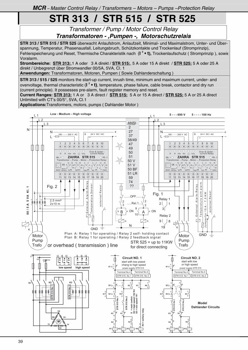
MCR – Master Control Relay / Transformers – Motors – Pumps –Protection Relay
STR 313 / STR 515 / STR 525
Transformer / Pump / Motor Control Relay Transformatoren - ,Pumpen -, Motorschutzrelais
STR 313 / STR 515 / STR 525 überwacht Anlaufstrom, Anlaufzeit, Minimal- und Maximalstrom, Unter- und Über-spannung, Temperatur, Phasenausfall, Leitungsbruch, Schützkontakte und Trockenlauf (Stromprinzip), Fehlerspeicherung und Reset, Thermische Charakteristik nach (I 2 • t), Trockenlaufschutz ( Stromprinzip ), sowie Voralarm. Strombereiche: STR 313:,1 A oder 3 A direkt / STR 515:, 5 A oder 15 A direkt / STR 525: 5 A oder 25 A direkt / Unbegrenzt über Stromwandler 00/5A, 5VA, Cl. 1 Anwendungen: Transformatoren, Motoren, Pumpen ( Sowie Dahlanderschaltung )
STR 313 / 515 / 525 monitors the start-up current, inrush time, minimum and maximum current, under- and overvoltage, thermal characteristic (I 2 • t), temperature, phase failure, cable break, contactor and dry run (current principle). It possesses pre-alarm, fault register memory and reset. Current Ranges: STR 313: 1 A or 3 A direct / STR 515: 5 A or 15 A direct / STR 525: 5 A or 25 A direct Unlimited with CT’s 00/5°, 5VA, Cl.1 Applications:Transformers, motors, pumps ( Dahlander Motor )
& � (
& � �
& � )
& � (
& � �
& � )
9 � � + � �
@
@
�
�
�
� = 8 � � �
� � ( * � �
( 3 : � & � % � B 8 . � & � � = ; � 9 3 � 6 � = �� � & � & � & � � � � � � � � � � � � � � � & � & � & � & � � � � � � E
� � � � � % 2 � 3 � � � � ( � � � � � � � � � � � � ? � 3 � � � � � � � � � � - � � � � � � � � � � � � � � �
� � � � � 6 2 � 3 � � � � ( � � � � � � � � � � � � ? � 3 � � � � � � � � � � " � � � � � � �
������$�����$��*�+��
@
&
@
&
@
&
4 � 3 � 8 � 8 � B � � � � � � � ( ( @ C
� � � � � � � � � � � � � � � � � � �
� . � $ � � � ! � ? � % !( ; 8 � - � - � - � - � � 8 * � $ � � % !
����� ���%� �
-3�� �
���
�� ����4����
����� ��3����
� . � $ � � � ! � ? � % !( ; 8 � - � - � - � - � � 8 * � $ � � % !
&
#
#
&
#
: # �
3 � � � � (
)
� (
3 � � � � �
( *
< ;@
�
)
+ + + + + + + + ' 9 9 + + + + + + +
%
<
( *
+ + + + + 3 � � + ( + + + +
@
@
�
)
' #' #
#
7 � � �
� � � �
� � �
7 � � �
� � � �
� � �
: # �
����� ���%� �
-3�� �
���
�� ��������� � �
����� ��3����
R��
�����(8�%�-��,=8�@C
9 � � + � (
& � � & ' � � � � � � ( � � � � ) � ) ) & � � * � � � �
6
% # 4 �
� � �
� � , �
� ) ,
) ; ? . <
� . ,
� . <
� 8 *
� 8 (
8 * � $
8 ( � $
8 * � 6 9
8 ( � & 3
� 8 <
� , .
� � 5 5 � �
( � ) . 8 / , ; < ( *
( ( ( � ( ) ( . ( 8 ( / ( , ( ; ( < � *
7 � � � � �
: � � � �
3 � & + � (
*) *
/ � .
( � ( ;
*8
(.
� )
� � � � E % F%
� � � � � � � � E % F� �
� � � � � � � � E % F� � �
� � � � E � � � F%
� % � � � � � � � � � � � +
* 8
(.
� )
* ) *
/ � .
( � ( ;
* ) *
/ � .
( � ( ;
3 � 4 � �
� � � � � � � � - = � � � � � � - = � 7 � � � � - = � � � � � � � � � � � 3 � � �
' � � O � � � � � � - �
� � � � � � 3 � � �
3 � & + � �
� %
, $ � � $ � � � � � � � � � �
� � � � � � E � � � F�
� � � � � � E � � � F�
�
%
* � * � * �
* � * � * �
* � * �
* � * �
* �* �
* �* �* �
� �
� �
� �
$�
$�
$�
$�
$�
$�
$�
$�
��
��
$�
��
��
��
��
��
��
��
��
��
��
��
��
��
��
��
��
��
��
��
��
��
��
��
��
* �
� ' � �
� )
� '� )
� '
����/�.� 4��: 62;
���/�; =;�����B��*�G*�
���/��3:�����B��*��
*��/��- � �1��1����
4 � 3 � 8 ( 8 + � # � � (
� � � � � � � # � + .
� � � � � � � � � � � � 4 � 3 � 8 ( 8
� � � � � � � # � + .
��
��
���������3+�
���������3+�
���������3��
� 1 2 8 6 � � # + � �� ' � � � )
� ' � � � )
(�
(�
(�
� ' � � � )
� ' � � � )
(�
(�
(�
� 3 : � � � � � B ; = ; � � � � � B
( �
( �
( �� � � � � � � � � � � � � � � � � �
� � � � � � � � � � � � � � � � � �
4 � 3 � 8 ( 8 + � # � � �
* � * �
* � * �
* � * �
* � * �
� �
� �
� �
$�
$�
$�
$�
$�
$�
��
��
��
��
��
��
��
��
��
��
��
��
��
��
��
��
��
��
��
��
��
��
* �
4 � 3 � 8 ( 8 + � # � � (
� � � � � � � # � + .
� � � � � � � � � � � � 4 � 3 � 8 ( 8
� � � � � � � # � + .
��
��
���������3+�
���������3+�
� � � � � � � � � � � � �
� � � � � � � � � � � �
4 � 3 � 8 ( 8 + � # � � �
���������3��
� � ; � � 4 B � 1 � � 1 2 8 6 �
% 3 B � �
� 1 2 8 6 � � # + � �
39
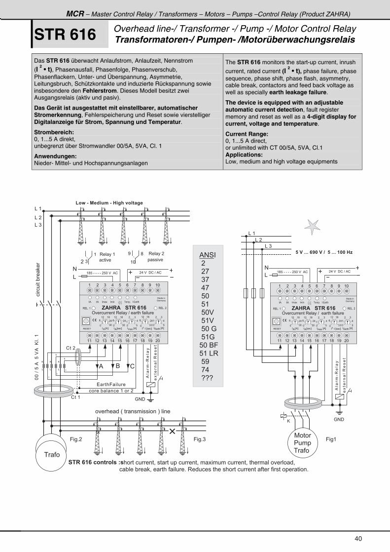
MCR – Master Control Relay / Transformers – Motors – Pumps –Control Relay (Product ZAHRA)
STR 616 Overhead line-/ Transformer -/ Pump -/ Motor Control RelayTransformatoren-/ Pumpen- /Motorüberwachungsrelais
Das STR 616 überwacht Anlaufstrom, Anlaufzeit, Nennstrom
(I 2 • t), Phasenausfall, Phasenfolge, Phasenverschub,
Phasenflackern, Unter- und Überspannung, Asymmetrie, Leitungsbruch, Schützkontakte und induzierte Rückspannung sowie insbesondere den Fehlerstrom. Dieses Modell besitzt zwei Ausgangsrelais (aktiv und pasiv).
Das Gerät ist ausgestattet mit einstellbarer, automatischer Stromerkennung, Fehlerspeicherung und Reset sowie vierstelliger Digitalanzeige für Strom, Spannung und Temperatur.
Strombereich: 0, 1...5 A direkt, unbegrenzt über Stromwandler 00/5A, 5VA, Cl. 1
Anwendungen: Nieder- Mittel- und Hochspannungsanlagen
The STR 616 monitors the start-up current, inrush
current, rated current (I 2 • t), phase failure, phase
sequence, phase shift, phase flash, asymmetry, cable break, contactors and feed back voltage as well as specially earth leakage failure.
The device is equipped with an adjustable automatic current detection, fault register memory and reset as well as a 4-digit display for current, voltage and temperature.
Current Range: 0, 1...5 A direct, or unlimited with CT 00/5A, 5VA, Cl.1 Applications: Low, medium and high voltage equipments
& � (
& � �
& � )
@
� � � � + + + � � � � � � � � � � + + + � � � � � � E
� . � $ � � � ! � ? � % !( ; 8 � - � - � - � - � � 8 * � $ � � % !
#
&
7 � � �
� � � �
� � �
��%� �
-3�� �
����� ��3����
( � ) . 8 / , ; < ( *
( ( ( � ( ) ( . ( 8 ( / ( , ( ; ( < � *
7 � � � � �
: � � � �
3 � & + � (
* 8
( .
� )
� � � � E % F%
� � � � � � � � E % F� �
� � � � E � � � F%
� % � � � � � � � � � � � +
* 8
(.
� )
* ) *
/ � .
( � ( ;
* ) *
/ � .
( � ( ;
3 � 4 � �
3 � & + � �
� %
, $ � � $ � � � � � � � �
� � � � �
� � � � � � � � � E % F� � �
' � � � � � � � 3 � � � � ? � � � � � � � � � � �
*) *
/ � .
( � ( ;
� � � � � � E � � � F�
: # �
�
�
�
**�?�8�%��8�$%��@�+�(
@
&
@
&
@
&
��%� �
-3�� �
����� ��3����
� . � $ � � � ! � ? � % !( ; 8 � - � - � - � - � � 8 * � $ � � % !
&
#
3 � � � � (
)�
(
( *
< ;
& ' � � � � � � ( � � � � ) � ) ) & � � * � � � �
� � � �
3 � � � � �
� � � � �
( 3 : � & � % � B 8 . � & � � = ; � 9 3 � 6 � = �
& � (
& � �
& � )
� � � 9 � � � �
� � �
� � � � � � 2 3 4 6 1 3 � � � 7 � � � � � � � � � � = � � � � � � � � � � � � � = � � � � � � � � � � � � � = � � � � � � � � � � � � =
� � � � � � � � � � � � � � � � � � � � � � � � � � � � � � � � " � � � " � = � � � � � � � � � � + � 3 � � � � � � � � � � � � � � � � � � � � � � � � � � � � � � � � � � � � � � +
�������"� �
� � �
% 6 !
( � ) . 8 / , ; < ( *
( ( ( � ( ) ( . ( 8 ( / ( , ( ; ( < � *
7 � � � � �
: � � � �
3 � & + � (
* 8
( .
� )
� � � � E % F%
� � � � � � � � E % F� �
� � � � E � � � F%
� % � � � � � � � � � � � +
* 8
(.
� )
* ) *
/ � .
( � ( ;
* ) *
/ � .
( � ( ;
3 � 4 � �
3 � & + � �
� %
, $ � � $ � � � � � � � �
� � � � �
� � � � � � � � � E % F� � �
' � � � � � � � 3 � � � � ? � � � � � � � � � � �
*) *
/ � .
( � ( ;
� � � � � � E � � � F�
� � � � " � � � � � ( � � � �
! � � (
! � � �
� � # � �
: # �
% # 4 �
� � �
� � , �
� ) ,
� . ,
� 8 *
� 8 (
� 8 * $
� 8 ( $
� 8 * � :
� 8 ( :
8 * � 6 9
8 ( � & 3
� 8 <
� , .
� 5 5 5 � �
40
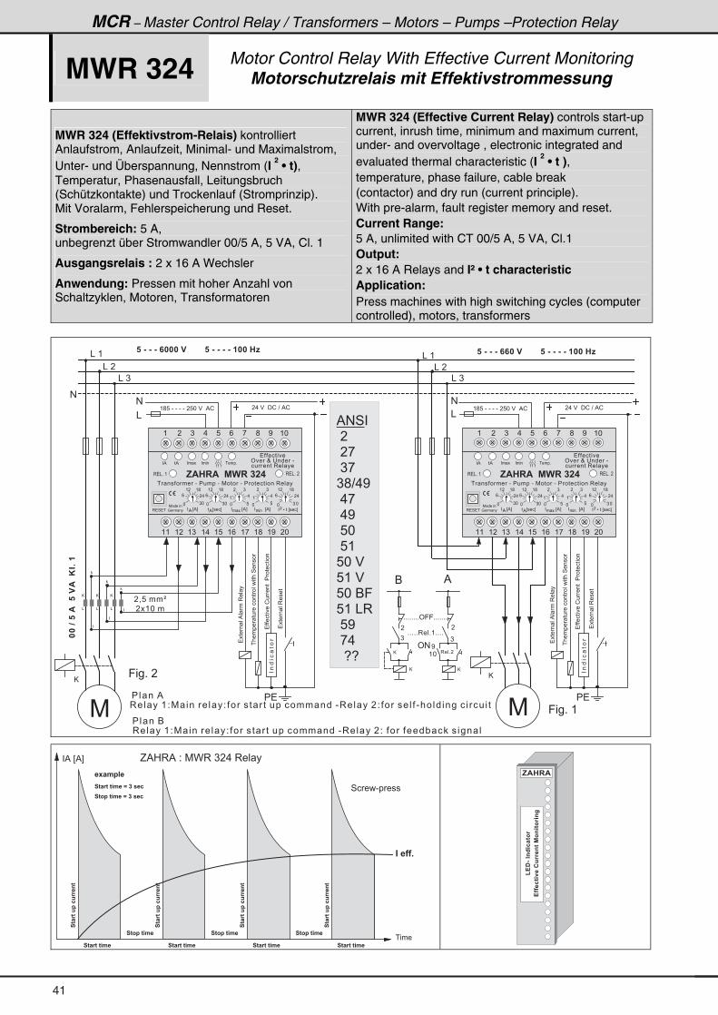
MCR – Master Control Relay / Transformers – Motors – Pumps –Protection Relay
MWR 324 Motor Control Relay With Effective Current Monitoring Motorschutzrelais mit Effektivstrommessung
MWR 324 (Effektivstrom-Relais) kontrolliert Anlaufstrom, Anlaufzeit, Minimal- und Maximalstrom, Unter- und Überspannung, Nennstrom (I
2 • t),
Temperatur, Phasenausfall, Leitungsbruch (Schützkontakte) und Trockenlauf (Stromprinzip). Mit Voralarm, Fehlerspeicherung und Reset.
Strombereich: 5 A, unbegrenzt über Stromwandler 00/5 A, 5 VA, Cl. 1
Ausgangsrelais : 2 x 16 A Wechsler
Anwendung: Pressen mit hoher Anzahl von Schaltzyklen, Motoren, Transformatoren
MWR 324 (Effective Current Relay) controls start-up current, inrush time, minimum and maximum current, under- and overvoltage , electronic integrated and evaluated thermal characteristic (I
2 • t ),
temperature, phase failure, cable break (contactor) and dry run (current principle). With pre-alarm, fault register memory and reset. Current Range: 5 A, unlimited with CT 00/5 A, 5 VA, Cl.1 Output: 2 x 16 A Relays and I² • t characteristic Application: Press machines with high switching cycles (computer controlled), motors, transformers
& � (
& � �
& � )
& � (
& � �
& � )
7
9 � � + � �
7
@@
�
�
�
� = 8 � � � Q
� � ( * � �
� � & � & � & � � � � � � � � � � � � � � � � & � & � & � & � � � � � � E� � & � & � & � � � � � � � � � � � � � � & � & � & � & � � � � � � E
@
6
�
)
+ + + + + + + + ' 9 9 + + + + + + +
' #
@
%
�
)
<
( *3 � � + �
+ + + + + 3 � � + ( + + + +
@
� � � � %
������$�����$��*�+��
@
&
@
&
@
&
� . � $ � � � ! � ? � % !( ; 8 � - � - � - � - � � 8 * � $ � � % !
����� ��
���������!���������������
����� ��
����� ��%� ��3�� �
� �
����� ��%� ��3�� �
������ ����������������4����
����� ��3����
� . � $ � � � ! � ? � % !( ; 8 � - � - � - � - � � 8 * � $ � � % !
&
#
#
&
#
� �
������ ����������������4����
���������!���������������
����� ��3����
� 3 � � � � ( 2 7 � � � � � � 2 � � � � � � � � � � � � � � � � � - 3 � � � � � 2 � � � � � � � - � � � � � � � � � � � � � �
9 � � + � (
� � � � 6
� 3 � � � � ( 2 7 � � � � � � 2 � � � � � � � � � � � � � � � � � - 3 � � � � � 2 � � � � � � � � " � � � � � � �
( � ) . 8 / , ; < ( *
( ( ( � ( ) ( . ( 8 ( / ( , ( ; ( < � *
7 � � � � �
: � � � �
3 � & + � (
*) *
/ � .
( � ( ;
*8
(.
� )
� � � � E % F%
� � � � � � � � E % F� �
� � � � � � � � E % F� � � � � � � L � � � E � � � F
�� � � � E � � � F%
� % � % � � � � � � � � � � � +
* 8
(.
� )
* ) *
/ � .
( � ( ;
* ) *
/ � .
( � ( ;
3 � 4 � �
� � � � � � � � - � � � � � � - � 7 � � � � - � � � � � � � � � � � 3 � � �
� � � � � � � �
' � � O � � � � � � - �
� � � � � � 3 � � � �
3 � & + � �, $ � � $ � � % ) � � � � �
% # 4 �
� � �
� � , �
� ) ,
) ; ? . <
� . ,
� . <
� 8 *
� 8 (
8 * � $
8 ( � $
8 * � 6 9
8 ( � & 3
� 8 <
� , .
� � 5 5 � �
�6�16�8��2811�46
� 6 3 � � 6 . �
� � � �
� % � E % F
4 � � � - � � � �
" � � � � +
G % 0 3 % � 2 � 7 C 3 � ) � . � 3 � � �
� 6 � 1 6 � 6 . �
�6�16�8��2811�46
� 6 3 � � 6 . �
� 6 � 1 6 � 6 . �
�6�16�8��2811�46
� 6 3 � � 6 . �
� 6 � 1 6 � 6 . �
�6�16�8��2811�46
� 6 � 1 6 � 6 . �
" � � � � +
� 6 � 1 6 � 6 . � � / � � � � � 2
� 6 3 � � 6 . � � / � � � � � 2
� - � . � � �
, $ � � $
!���26 9���811�46�%34 631 4=
(!�&�"4B 2�631
41
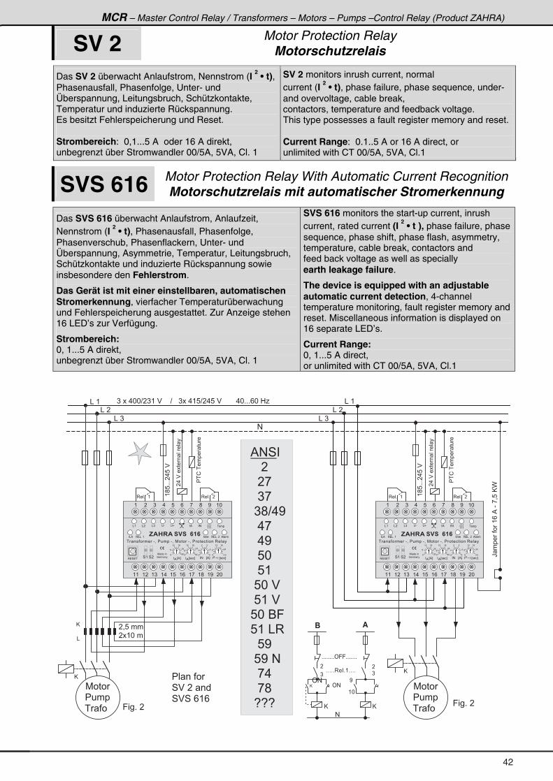
MCR – Master Control Relay / Transformers – Motors – Pumps –Control Relay (Product ZAHRA)
SV 2 Motor Protection Relay Motorschutzrelais
Das SV 2 überwacht Anlaufstrom, Nennstrom (I 2 • t),
Phasenausfall, Phasenfolge, Unter- und Überspannung, Leitungsbruch, Schützkontakte, Temperatur und induzierte Rückspannung. Es besitzt Fehlerspeicherung und Reset. Strombereich: 0,1...5 A oder 16 A direkt, unbegrenzt über Stromwandler 00/5A, 5VA, Cl. 1
SV 2 monitors inrush current, normal current (I
2 • t), phase failure, phase sequence, under-
and overvoltage, cable break, contactors, temperature and feedback voltage. This type possesses a fault register memory and reset. Current Range: 0.1..5 A or 16 A direct, or unlimited with CT 00/5A, 5VA, Cl.1
SVS 616 Motor Protection Relay With Automatic Current Recognition Motorschutzrelais mit automatischer Stromerkennung
Das SVS 616 überwacht Anlaufstrom, Anlaufzeit, Nennstrom (I
2 • t), Phasenausfall, Phasenfolge,
Phasenverschub, Phasenflackern, Unter- und Überspannung, Asymmetrie, Temperatur, Leitungsbruch, Schützkontakte und induzierte Rückspannung sowie insbesondere den Fehlerstrom.
Das Gerät ist mit einer einstellbaren, automatischen Stromerkennung, vierfacher Temperaturüberwachung und Fehlerspeicherung ausgestattet. Zur Anzeige stehen 16 LED’s zur Verfügung.
Strombereich: 0, 1...5 A direkt, unbegrenzt über Stromwandler 00/5A, 5VA, Cl. 1
SVS 616 monitors the start-up current, inrush current, rated current (I
2 • t ), phase failure, phase
sequence, phase shift, phase flash, asymmetry, temperature, cable break, contactors and feed back voltage as well as specially earth leakage failure.
The device is equipped with an adjustable automatic current detection, 4-channel temperature monitoring, fault register memory and reset. Miscellaneous information is displayed on 16 separate LED’s.
Current Range: 0, 1...5 A direct, or unlimited with CT 00/5A, 5VA, Cl.1
& � (
& � �
& � )
) � � � . * * ? � ) ( � $ � � � � ? � � � ) � � . ( 8 ? � . 8 � $ � � � � � � � . * + + + / * � 0 1
@
& � )
& � �
& � (
@
&
R �������(/�%�-�,=8�@C
� = 8 � � �
� � ( * � �
#
(;8+++�.8�$�
��!������ ���
(;8+++�.8�$�
�.�$������ ���� �
3 � � + � � ( 3 � � + � � �
@
�
�
)
+ + + + + + + + ' 9 9 + + + + + + +
$
<
( *
+ + + + + 3 � � + ( + + + +
@
@
�
)
' #
' #
#
��!������ ���
�.�$������ ���� �
3 � � + � � ( 3 � � + � � �
9 � � + � �
7 � � �
� � � �
� � �
7 � � �
� � � �
� � �
� � � � � �
4 $ � � � � �
4 $ 4 � / ( /9 � � + � �
( � ) . 8 / , ; < ( *
( ( ( � ( ) ( . ( 8 ( / ( , ( ; ( < � *
7 � � � � �
: � � � �
3 � & + � �3 � & + � (
* ) *
/� .
( � ( ;
� � � � E % F%
� # � � � E % F � � � � L � � � E � � � F�
� � � � E � � � F%
& ( & � & ) � -
* 8
(.
� )
*) *
/� .
( � ( ;
* ) *
/
� .
( � ( ;
, $ � � $ � � � � � �
3 � 4 � �4 ( 4 �
� % � # � � � �� �
� � � � % � �� & %
� � � � � � � � - = � � � � � � - = � 7 � � � � - = � � � � � � � � � � � 3 � � �
@
% # 4 �
� � � �
� � � ,
� � ) ,
� ) ; ? . <
� � . ,
� � . <
� � 8 *
� � 8 (
� 8 * � $
� 8 ( � $
8 * � 6 9
8 ( � & 3
� � 8 <
� 8 < � #
� � , .
� � , ;
� 5 5 5
42
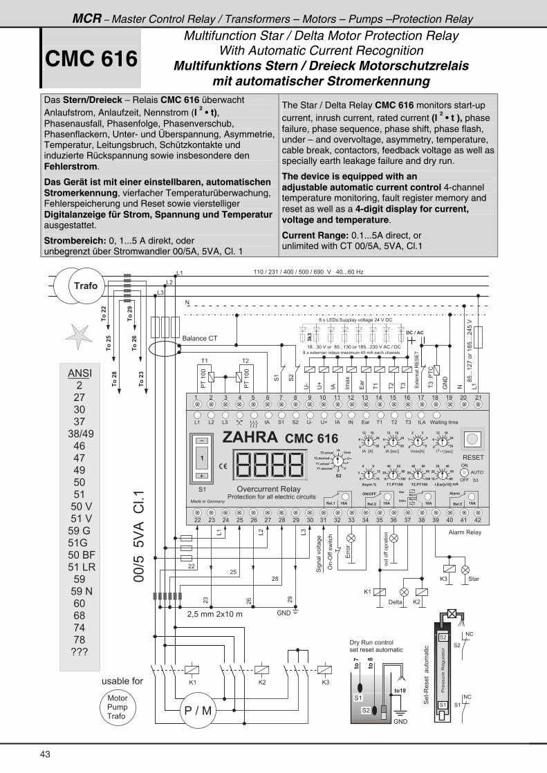
MCR – Master Control Relay / Transformers – Motors – Pumps –Protection Relay
CMC 616 Multifunction Star / Delta Motor Protection Relay
With Automatic Current Recognition Multifunktions Stern / Dreieck Motorschutzrelais
mit automatischer Stromerkennung
Das Stern/Dreieck – Relais CMC 616 überwacht Anlaufstrom, Anlaufzeit, Nennstrom (I
2 • t),
Phasenausfall, Phasenfolge, Phasenverschub, Phasenflackern, Unter- und Überspannung, Asymmetrie, Temperatur, Leitungsbruch, Schützkontakte und induzierte Rückspannung sowie insbesondere den Fehlerstrom.
Das Gerät ist mit einer einstellbaren, automatischen Stromerkennung, vierfacher Temperaturüberwachung, Fehlerspeicherung und Reset sowie vierstelliger Digitalanzeige für Strom, Spannung und Temperatur ausgestattet.
Strombereich: 0, 1...5 A direkt, oder unbegrenzt über Stromwandler 00/5A, 5VA, Cl. 1
The Star / Delta Relay CMC 616 monitors start-up current, inrush current, rated current (I
2 • t ), phase
failure, phase sequence, phase shift, phase flash, under – and overvoltage, asymmetry, temperature, cable break, contactors, feedback voltage as well as specially earth leakage failure and dry run.
The device is equipped with an adjustable automatic current control 4-channel temperature monitoring, fault register memory and reset as well as a 4-digit display for current, voltage and temperature.
Current Range: 0.1...5A direct, or unlimited with CT 00/5A, 5VA, Cl.1
�)�2��!
���(**
4(
# &(
;8+++(�,���(;8++++�.8�$
% � � � 3 � � �
@ (
( ( * � ? � � ) ( � ? � . * * � ? � 8 * * � ? � / < * � � $ � � � . * + + + / * � 0 1& (
& �
& )
#
� = 8 � � � � � � ( * � �
**?8��8$%��!�+(
: # �
6 � � � � � ! �
�-�
���
�(�
���
�)�
� �
�%�
�� ��
:#�4�
����� ��3�4��
��
� � � �
@ (
���������� ����
� (
���(**
� �
@ � @ )
� � ? � 7
� 1 � � 3
�3���
� �
�)
�/
�<
&(
&�
&)
( ; + + + ) * � $ � � � � ; 8 + + + ( ) * � � � ( ; 8 + + + � ) * � $ � % ! � ? � � !
; � � � & � � � + 4 � � � � � � � � � � � � � . � $ � � !
; � � � � � � � � � � � � � � � � � � � � � � . 8 � � % � � � � � � � � � � � �
6 3 � �
� �: # �
4 (
4 �
63��
63�
� � � 3 � � � � � � � � �
� � � � � � � � � � � � � � � �
� � � � $ �
�<�
7 � � �
� � � �
� � �
� � " � � � � �
& ( & � & ) � - � � � % � # � ( � � � )4 ( 4 � � & %
, $ � � $ � % � � �
3 � 4 � �
' � � � � � � � 3 � � �4 (
�
� � � � � � � � � � � � �
� � � � � � � � � � � � � � � � � � � � � � � � � � � � � � �
� �
4 )' 9 9
' #
% � � '
� � � + � � � � + � � � � + �
$ � � 1 .
� % � � E % F � � � � L � � � E � � � F�
�� �
� �
� � �
" $
" . � -
'
� � + B � � 1 � B
'
'
� � + � 2 6 8 � �
� � + B � � 1 � B
� � + � 2 6 8 � �� % � E � � � F
�� �
� �
� � �
� � � E % F
��
��
� �
�� �
� �
� � �
� � + � � � � �
� � � �
� � �
� � �
�
� � � �
� � � �
� �
" + ! � 1 > - � � ? . $
# � # � �
� $ � $ � $ � $
� � + � � � � �
� � � �
� � �
� � �
$ � � . + 5
� � �
�� �
�
C � � � � � � � � � �� � %
( � ) . 8 / , ; < ( * ( ( ( � ( ) ( . ( 8 ( / ( , ( ; ( < � * � (
� � � ) � . � 8 � / � , � ; � < ) * ) ( ) � ) ) ) . ) 8 ) / ) , ) ; ) < . * . ( . �
� 8
� ;
4��� ����� ��
'�-'���������
@ �
4 � @ )
� � � + �
� � � + �
� 6 � 1
� � � 6 �
4��-3������ ���� ����
��������3���� ��
4 �
4 (
# !
# !
4 (
4 �
�3���
�3���
�3��
�3��
�3���% # 4 �
� � � �
� � � ,
� � ) *
� � ) ,
) ; ? . <
� � . /
� � . ,
� � . <
� � 8 *
� � 8 (
� 8 * � $
� 8 ( � $
8 < � :
8 ( :
8 * � 6 9
8 ( � & 3
� � 8 <
� 8 < � #
� � / *
� � / ;
� � , .
� � , ;
� 5 5 5
43
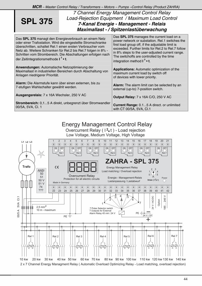
MCR – Master Control Relay / Transformers – Motors – Pumps –Control Relay (Product ZAHRA)
SPL 375 7 Channel Energy Management Control Relay
Load-Rejection Equipment / Maximum Load Control 7-Kanal Energie - Management - Relais Maximallast - / Spitzenlastüberwachung
Das SPL 375 managt den Energieverbrauch an einem Netz oder einer Trafostation. Wird die eingestellte Stromschranke überschritten, schaltet Rel.1 einen ersten Verbraucher vom Netz ab. Weitere Schranken für Rel.2 bis Rel.7 folgen in 8% - Schritten vom Strombereich. Die Abschaltungen erfolgen nach der Zeitintegrationsmethode I
2 • t.
Anwendungen: Automatische Netzoptimierung der Maximallast in industriellen Bereichen durch Abschaltung von Anlagen niedrigerer Priorität. Alarm: Die Alarmstufe kann über einen externen, bis zu 7-stufigen Wahlschalter gewählt werden. Ausgangsrelais: 7 x 16A Wechsler, 250 V AC Strombereich: 0,1...5 A direkt, unbegrenzt über Stromwandler00/5A, 5VA, Cl. 1
Das SPL 375 manages the current load on a power network or substation. Rel.1 switches the first load group off, if the adjustable limit is exceeded. Further limits for Rel.2 to Rel.7 follow in 8% steps to the user-adjusted current range. The switchoffs are controlled by the time integration method I
2 • t.
Applications: Automatic optimization of the maximum current load by switch off of devices with lower priority. Alarm: The alarm limit can be selected by an external (up-to) 7-position switch. Output Relay: 7 x 16A C/O, 250 V AC Current Range: 0.1...5 A direct. or unlimited with CT 00/5A, 5VA, Cl.1
� = 8 � � �
( * � � � - � � � � � � �
(
�
).
8
/
,
( � ( � ( �
�.�$�?�%!?�!
(;8�+++��.8�$�
**?8�%���8$%��!�+(
� �
& � � � $ � � � � � = � 7 � � � � � � $ � � � � � = � 0 � � � � $ � � � � �
� �
3 � � � ( 3 � � � ,3 � � � /3 � � � 83 � � � .3 � � � )3 � � � �
� 1 � � 3
� � � � , � ! � � � � � � � � � � � � 7 � � � � � � � 3 � � � � H � % � � � � � � � � ' � � � � � ' � � � � � 1 � � � � 3 � � � � - � & � � � � � � � � � � = � � � � � � � � > � � � � � � I
( * � � � * � � ) * � � . * � � 8 * � � / * � � , * � � ; * � � < * � � ( * * � � ( ( * � � ( � * � � ( ) * � � ( . * � �
, � ' � � � � � � � � � � � � � � � �
% � � � 3 � � � � . 8 � � % � ? � � . � $
� . � $ � ? � � !
, � � � � � � � 4 � � � � � � � � � � � � �
�
' � � � � � � � 3 � � � � H � � � � � � � � I � - � & � � � � > � � � � � ��
� � � � � � 7 � � � � � � � � ! � � � � � � 3 � � �
� � � ) � . � 8 � / � , � ; � < ) * ) ( ) � ) ) ) . ) 8 ) / ) , ) ; ) < . * . ( . �
' # ' 9 9
, $ � � $ � & � � � ( � � � �
' � � � � � � � 3 � � �
� � � � � � � � � � � � �
� � � � � � � � � � � � � � � � � � � � � � � � � � � � � � �� � � �
3 � � + (
" . � - � H � " � � � 6 � I
%
* 8
( .
� )
�
� � � � � � 7 � � � � � � � � 3 � � �
& � � � � � � � � � � � ? � ' � � � � � � > � � � � � �
� � � � � � � - � 7 � � � � � � � - 3 � � � �
& � � � � � � � � � � ? � & � � " � � �
' # ' 9 9
3 � � + �
' # ' 9 9
3 � � + )
' # ' 9 9
3 � � + .
' # ' 9 9
3 � � + 8
' # ' 9 9
3 � � + /
' # ' 9 9
3 � � + ,
'�����
% # 4 �
� � � 8 *
� � � 8 (
� 8 * � $
� 8 ( � $
� � , .
� 5 5 5
( � ) . 8 / , ; < ( * ( ( ( � ( ) ( . ( 8 ( / ( , ( ; ( < � * � (
44
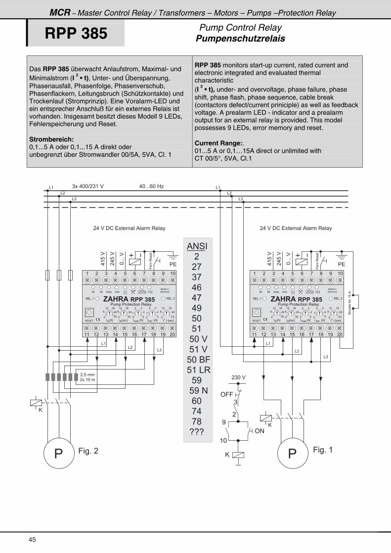
*
(
MCR – Master Control Relay / Transformers – Motors – Pumps –Protection Relay
RPP 385 Pump Control Relay Pumpenschutzrelais
Das RPP 385 überwacht Anlaufstrom, Maximal- und Minimalstrom (I
2 • t), Unter- und Überspannung,
Phasenausfall, Phasenfolge, Phasenverschub, Phasenflackern, Leitungsbruch (Schützkontakte) und Trockenlauf (Stromprinzip). Eine Voralarm-LED und ein entsprecher Anschluß für ein externes Relais ist vorhanden. Insgesamt besitzt dieses Modell 9 LEDs, Fehlerspeicherung und Reset.
Strombereich: 0,1...5 A oder 0,1...15 A direkt oder unbegrenzt über Stromwandler 00/5A, 5VA, Cl. 1
RPP 385 monitors start-up current, rated current and electronic integrated and evaluated thermal characteristic (I
2 • t), under- and overvoltage, phase failure, phase
shift, phase flash, phase sequence, cable break (contactors defect/current priniciple) as well as feedback voltage. A prealarm LED - indicator and a prealarm output for an external relay is provided. This model possesses 9 LEDs, error memory and reset. Current Range:. 01...5 A or 0,1…15A direct or unlimited with CT 00/5°, 5VA, Cl.1
� �
9���3����
*+++�$
�.8�$
.(8�$
& (
& �
& )
� = 8 � � �
� � � ( * � �
� . � $ � � ! � � � � � � � � % � � � 3 � � �
) � � . * * ? � ) ( � $ � � � � � � � � � � � � � � � � � � � � � � � � . * + + + / * � 0 1
� �
�
@
� �
9���3����
*+++�$
�.8�$
.(8�$
& (
& �
& )
� . � $ � � ! � � � � � � � � % � � � 3 � � �
� �
@
6A� ���A�(8�%
& (
& �
& )
& (
& �
& )
9 � � + � � 9 � � + � (
' 9 9
' #
)
�
<
( *
@
� ) * � $
�
% # 4 �
� � � �
� � � ,
� � ) ,
� � . /
� � . ,
� � . <
� � 8 *
� � 8 (
� 8 * � $
� 8 ( � $
8 * � 6 9
8 ( � & 3
� � 8 <
� 8 < � #
� � / *
� � , .
� � , ;
� 5 5 5
7 � � � � �
: � � � �
3 � & + � (
*) *
/ � .
( � ( ;
*8
(.
� )
� � � � E % F%
� � � � � � � � E % F� �
� � � � � � � � E % F� � �
� � � � E � � � F%
� % � � � � � � �
* 8
(.
� )
* ) *
/ � .
( � ( ;
* ) *
/ � .
( � ( ;
3 � 4 � �
3 � & + � �
� %
� � � � � � E � � � F�
� �
, $ � � $ � � � � � � �� � � � � � � � � � � � � � � 3 � � �
( � ) . 8 / , ; < ( *
( ( ( � ( ) ( . ( 8 ( / ( , ( ; ( < � *
7 � � � � �
: � � � �
3 � & + � (
*) *
/ � .
( � ( ;
*8
(.
� )
� � � � E % F%
� � � � � � � � E % F� �
� � � � � � � � E % F� � �
� � � � E � � � F%
� % � � � � � � �
* 8
(.
� )
* ) *
/ � .
( � ( ;
* ) *
/ � .
( � ( ;
3 � 4 � �
3 � & + � �
� %
� � � � � � E � � � F�
� �
, $ � � $ � � � � � � �� � � � � � � � � � � � � � � 3 � � �
( � ) . 8 / , ; < ( *
( ( ( � ( ) ( . ( 8 ( / ( , ( ; ( < � *
45
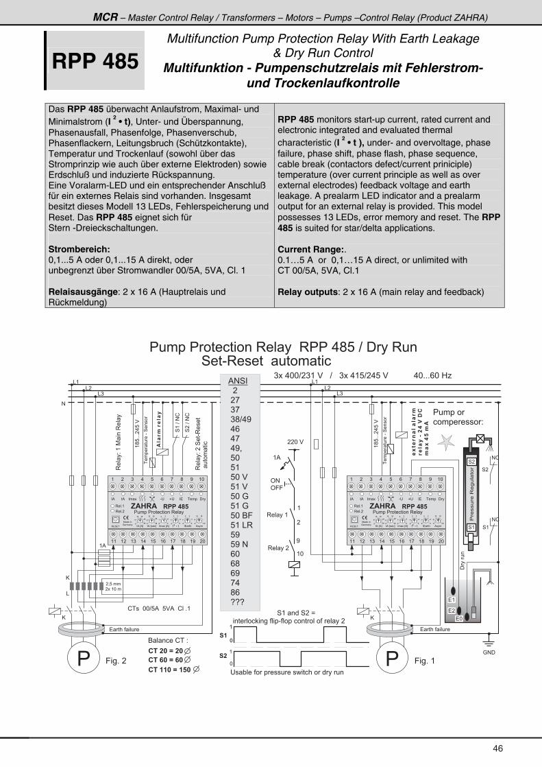
MCR – Master Control Relay / Transformers – Motors – Pumps –Control Relay (Product ZAHRA)
RPP 485 Multifunction Pump Protection Relay With Earth Leakage
& Dry Run Control Multifunktion - Pumpenschutzrelais mit Fehlerstrom-
und Trockenlaufkontrolle Das RPP 485 überwacht Anlaufstrom, Maximal- und Minimalstrom (I
2 • t), Unter- und Überspannung,
Phasenausfall, Phasenfolge, Phasenverschub, Phasenflackern, Leitungsbruch (Schützkontakte), Temperatur und Trockenlauf (sowohl über das Stromprinzip wie auch über externe Elektroden) sowie Erdschluß und induzierte Rückspannung. Eine Voralarm-LED und ein entsprechender Anschluß für ein externes Relais sind vorhanden. Insgesamt besitzt dieses Modell 13 LEDs, Fehlerspeicherung und Reset. Das RPP 485 eignet sich für Stern -Dreieckschaltungen. Strombereich: 0,1...5 A oder 0,1...15 A direkt, oder unbegrenzt über Stromwandler 00/5A, 5VA, Cl. 1 Relaisausgänge: 2 x 16 A (Hauptrelais und Rückmeldung)
RPP 485 monitors start-up current, rated current and electronic integrated and evaluated thermal characteristic (I
2 • t ), under- and overvoltage, phase
failure, phase shift, phase flash, phase sequence, cable break (contactors defect/current priniciple) temperature (over current principle as well as over external electrodes) feedback voltage and earth leakage. A prealarm LED indicator and a prealarm output for an external relay is provided. This model possesses 13 LEDs, error memory and reset. The RPP 485 is suited for star/delta applications. Current Range:. 0.1…5 A or 0,1…15 A direct, or unlimited with CT 00/5A, 5VA, Cl.1 Relay outputs: 2 x 16 A (main relay and feedback)
(;8+++�.8�$
& (
� = 8 � � �
� � � ( * � �
) � � . * * ? � ) ( � $ � � � ? � � � ) � � . ( 8 ? � . 8 � $ � � � � � � � � � � � . * + + + / * � 0 1
9 � � + � �
(;8+++�.8�$
� � � � � � � � �
�����
@
&
����� ����-�4����
$��1.
�1����
����� ����-�4����
6 � � � � � ! � � 2
� � � � � � / � � �
� � � � � / � �
� � � � � � � / � � � �
� � � � � � � � �
& �
& )
& (
& �
& )
#
�-6�14������1.
1�����&��������
.�-����.
$
( %
! � � � � * * ? 8 % � � 8 $ % � � ! � � + (
� �: # �
� (
� *
� �
4 � � - 3 � � � � � � � � � � � � � �
� � � � � � � � � � � � � � � 3 � � � � � 3 � � � . ; 8 � ? � � � � 3 � � �
' # �
' 9 9
( %
3 � � � � (
3 � � � � �
(
�
<
( *
3�� �2�(�7 ���3�� �
3�� �2���4��-3����
� ���� ���
9 � � + � (
� � " � � � � � � � � � � � � � � � � � � � � � � � � � � �
��������3���� ��
4 �
4 (
� � � � � � �
� � � � � � � � � 2
# !
# !
4 (
4 �
4��?�#!
4(�?�#!
� � * � $
� � � � � � � � � � � � � � � � � � � � � � � � 4 ( � � � � 4 � � B
� � � � � � � � � � � � � � � � - � � � � � � � � � � � � � � � � � � � �
*
(
*
(
� �
� �
� % � % � � �
7 � � � � �
: � � � �
, $ � � $ � � � � � � � � �
� � �
� � �
� �
��
� �
� � � A
� �
��
� �
�� �
� �
� � �
� � � � � � � � � � � � � � � 3 � � �
- � � � � � � � � � � �
�
� �
� � �
� � �
��
��
�
3 � � + (
3 � � + �
( ( ( � ( ) ( . ( 8 ( / ( , ( ; ( < � *
( � ) . 8 / , ; < ( *
3 � 4 � �
�
� � � � � � �� % � E % F � % � E � � � F � � � � E % F � � � � % � � �
@
�
@
�
% # 4 � �
� � �
� � ,
� ) ,
� ) ; ? . <
� . /
� . ,
� . < =
� 8 *
� 8 (
� 8 * � $
� 8 ( � $
� 8 * � :
� 8 ( � :
� 8 * � 6 9
� 8 ( � & 3
� 8 <
� 8 < � #
� / *
� / ;
� / <
� , .
� ; /
� 5 5 5
46
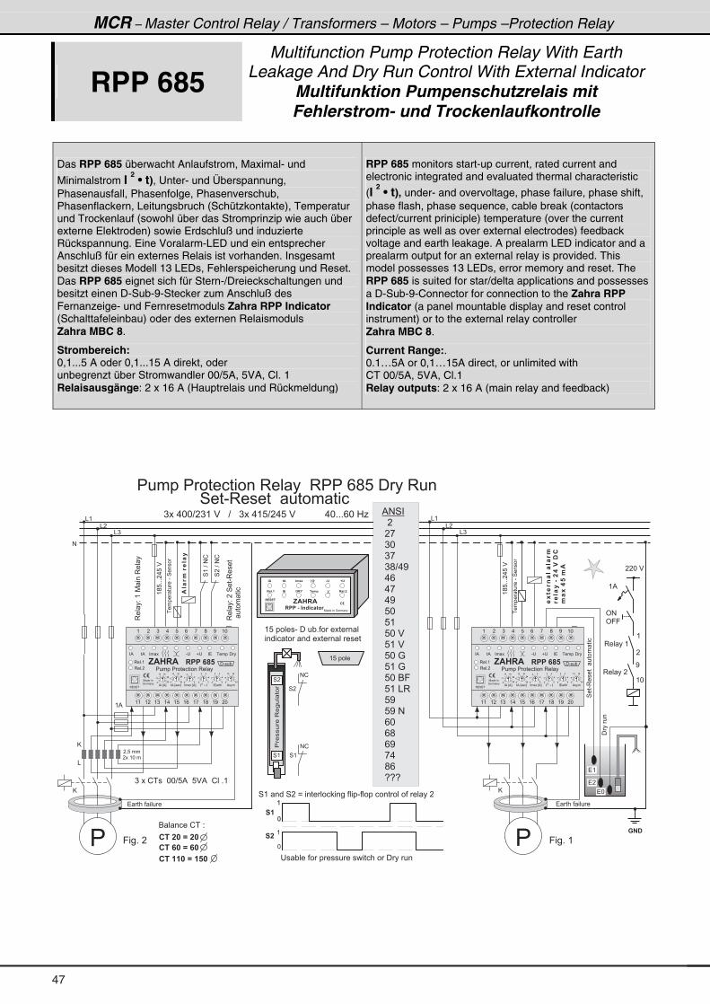
MCR – Master Control Relay / Transformers – Motors – Pumps –Protection Relay
RPP 685 Multifunction Pump Protection Relay With Earth
Leakage And Dry Run Control With External IndicatorMultifunktion Pumpenschutzrelais mit Fehlerstrom- und Trockenlaufkontrolle
Das RPP 685 überwacht Anlaufstrom, Maximal- und
Minimalstrom I 2 • t), Unter- und Überspannung,
Phasenausfall, Phasenfolge, Phasenverschub, Phasenflackern, Leitungsbruch (Schützkontakte), Temperatur und Trockenlauf (sowohl über das Stromprinzip wie auch über externe Elektroden) sowie Erdschluß und induzierte Rückspannung. Eine Voralarm-LED und ein entsprecher Anschluß für ein externes Relais ist vorhanden. Insgesamt besitzt dieses Modell 13 LEDs, Fehlerspeicherung und Reset. Das RPP 685 eignet sich für Stern-/Dreieckschaltungen und besitzt einen D-Sub-9-Stecker zum Anschluß des Fernanzeige- und Fernresetmoduls Zahra RPP Indicator (Schalttafeleinbau) oder des externen Relaismoduls Zahra MBC 8.
Strombereich: 0,1...5 A oder 0,1...15 A direkt, oder unbegrenzt über Stromwandler 00/5A, 5VA, Cl. 1 Relaisausgänge: 2 x 16 A (Hauptrelais und Rückmeldung)
RPP 685 monitors start-up current, rated current and electronic integrated and evaluated thermal characteristic
(I 2 • t), under- and overvoltage, phase failure, phase shift,
phase flash, phase sequence, cable break (contactors defect/current priniciple) temperature (over the current principle as well as over external electrodes) feedback voltage and earth leakage. A prealarm LED indicator and a prealarm output for an external relay is provided. This model possesses 13 LEDs, error memory and reset. The RPP 685 is suited for star/delta applications and possesses a D-Sub-9-Connector for connection to the Zahra RPP Indicator (a panel mountable display and reset control instrument) or to the external relay controller Zahra MBC 8.
Current Range:. 0.1…5A or 0,1…15A direct, or unlimited with CT 00/5A, 5VA, Cl.1 Relay outputs: 2 x 16 A (main relay and feedback)
(;8+++�.8�$
& (
� = 8 � � �
� � � ( * � �
) � � . * * ? � ) ( � $ � � � ? � � � ) � � . ( 8 ? � . 8 � $ � � � � � � � � � � � . * + + + / * � 0 1
9 � � + � �
(;8+++�.8�$
� � � � � � � � �
�����
@
&
����� ����-�4����
$��1.
�1����
����� ����-�4����
� � � � � � � � �
& �
& )
& (
& �
& )
#
�-6�14������1.
1�����&��������
.�-����.
$
( %
) � � � ! � � � � * * ? 8 % � � 8 $ % � � ! � � + (
� �� � �
� (
� *
� �
4 � � - 3 � � � � � � � � � � � � � �
� � � � � � � � � � � � � � � 3 � � � � � 3 � � � / ; 8 � � � � 3 � � �
3�� �2�(�7 ���3�� �
3�� �2���4��-3����
� ���� ���
9 � � + � (
4��?�#!
4(�?�#!
4��-3������ ���� ����
( 8 � � � � �
( 8 � � � � � � - � � � � " + � � � � � � � � �
� � � � � � � � � � � � � � � � � � � � � � �
( � ) . 8 / , ; < ( *
( ( ( � ( ) ( . ( 8 ( / ( , ( ; ( < � *
� % � % � � �
7 � � � � �
: � � � �
� � �
� � �
� �
��
� �
� � � A
� �
��
� �
�� �
� �
� � �
� � � � � � � � � � � � � � � 3 � � �
- � � � � � � � � � � �
�
� �
� � �
� � �
��
��
�
3 � � + (
3 � � + �
3 � 4 � �
�
� � � � � � �� % � E % F � % � E � � � F � � � � E % F � � � � % � � �
, $ � � $ � � � � � � � � � - � � "
7 � � � � � � : � � � �
, $ � � $
� � � � & � " 4 B 2 � 6 3 1
� ! � ! �
" $ 6 $ " . � - & ' D '
� � � + � " ! � � J � � . � � � � + �
6 � � � � � ! � � 2
� � � � � � / � � �
� � � � � / � �
� � � � � � � / � � � �
' # �
' 9 9
( %
3 � � � � (
3 � � � � �
(
�
<
( *
��������3���� ��
4 �
4 (
# !
# !
4 (
4 �
� � * � $
� � " � � � � � � � � � � � � � � � � � � � � � � � � � � �
4 ( � � � � 4 � � B � � � � � � � � � � � � � � � � - � � � � � � � � � � � � � � � � � � � �
*
(
*
(
� �
� �
@
�
@
�
% # 4 � �
� � �
� � ,
� ) *
� ) ,
� ) ; ? . <
� . /
� . ,
� . <
� 8 *
� 8 (
� 8 * � $
� 8 ( � $
� 8 * � :
� 8 ( � :
� 8 * � 6 9
� 8 ( � & 3
� 8 <
� 8 < � #
� / *
� / ;
� / <
� , .
� ; /
� 5 5 5
*
(
47
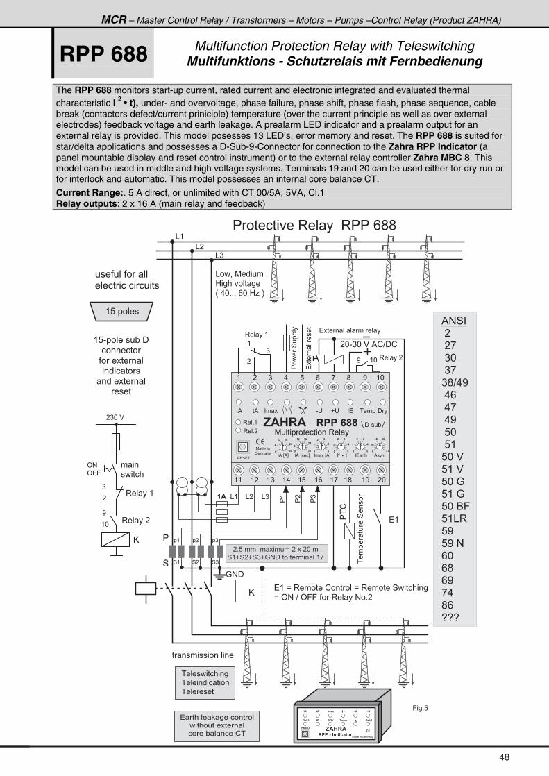
MCR – Master Control Relay / Transformers – Motors – Pumps –Control Relay (Product ZAHRA)
RPP 688 Multifunction Protection Relay with Teleswitching Multifunktions - Schutzrelais mit Fernbedienung
The RPP 688 monitors start-up current, rated current and electronic integrated and evaluated thermal characteristic I
2 • t), under- and overvoltage, phase failure, phase shift, phase flash, phase sequence, cable
break (contactors defect/current priniciple) temperature (over the current principle as well as over external electrodes) feedback voltage and earth leakage. A prealarm LED indicator and a prealarm output for an external relay is provided. This model posesses 13 LED’s, error memory and reset. The RPP 688 is suited for star/delta applications and possesses a D-Sub-9-Connector for connection to the Zahra RPP Indicator (a panel mountable display and reset control instrument) or to the external relay controller Zahra MBC 8. This model can be used in middle and high voltage systems. Terminals 19 and 20 can be used either for dry run or for interlock and automatic. This model possesses an internal core balance CT.
Current Range:. 5 A direct, or unlimited with CT 00/5A, 5VA, Cl.1 Relay outputs: 2 x 16 A (main relay and feedback)
& (
@
�����4�����
�
4
& �
& )
& ( & )
4 )
�(
��
�)
4 �4 (
& �
: # �
� $
3 � � � � �< ( *
� � � � � � � � � 3 � � � � � 3 � � � / ; ;
� * - ) * � $ � % ! ? � !
� � � � � � � � � � � � � � �
����� ����4����
��!
& � � = � 7 � � � � � � =
0 � � � � � � � � �
H � . * + + + � / * � 0 1 � I
� (
� ( � B � 3 � � � � � � ! � � � � � � B � 3 � � � � � � 4 � � � � � � � � �
B � ' # � ? � ' 9 9 � � � � 3 � � � � # � + �
)
�
<
( *
' #
' 9 9
3 � � � � (
3 � � � � �
� ) * � $
� � �
� � � � � �
@
� � � � � � � � � � � � �
� � � � � � � � � � � � � � �
3 � � � � (
� � � � � � � � � � � � � � �
� � � � � � � � � � � � � � �
� � � � " � � � � � ! �
( 8 � � � � � �
( 8 - � � � � � � � " � � �
� � � � � � � �
� � � � � � � � � �
� � � � � � � �
� � � � � � � � � �
� � � �
� � � � � � � � � � � � �
� � � � � � � � � � � � �
� � � � � � � �
� � � � � � � � � � � � �
����� ������
9 � � + 8
� + 8 � � � � � � � � � � � � � � � � � * � �
4 ( � 4 � � 4 ) � : # � � � � � � � � � � � � ( ,
7 � � � � � � : � � � �
, $ � � $
� � � � & � " 4 B 2 � 6 3 1
� ! � ! �
" $ 6 $ " . � - & ' D '
� � � + � " ! � � J � � . � � � � + �
� )� �� (
( � ) . 8 / , ; < ( *
( ( ( � ( ) ( . ( 8 ( / ( , ( ; ( < � *
� % � % � � �
7 � � � � �
: � � � �
� � �
� � �
� �
��
� �
� � � A
� �
��
� �
�� �
� �
� � �
- � � � � � � � � � � �
�
� �
� � �
� � �
��
� �
�
3 � � + (
3 � � + �
3 � 4 � �
�
� � � � � � �� % � E % F � % � E � � � F � � � � E % F � � � � % � � �
� - � � ", $ � � $ � � � � � � �
7 � � � � � � � � � � � � � � 3 � � �
�
(
)
% # 4 �
� �
� � ,
� ) *
� ) ,
) ; ? . <
� . /
� . ,
� . <
� 8 *
� 8 (
8 * � $
8 ( � $
8 * � :
8 ( � :
8 * � 6 9
8 ( & 3
8 <
8 < � #
/ *
/ ;
/ <
, .
; /
5 5 5
48
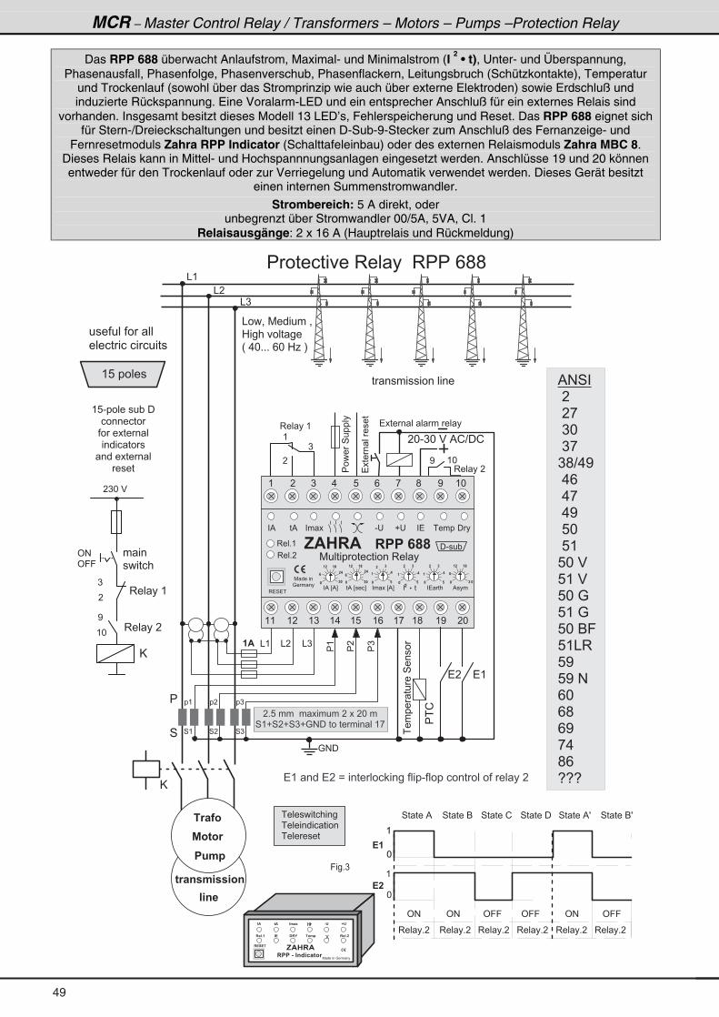
MCR – Master Control Relay / Transformers – Motors – Pumps –Protection Relay
Das RPP 688 überwacht Anlaufstrom, Maximal- und Minimalstrom (I 2 • t), Unter- und Überspannung,
Phasenausfall, Phasenfolge, Phasenverschub, Phasenflackern, Leitungsbruch (Schützkontakte), Temperatur und Trockenlauf (sowohl über das Stromprinzip wie auch über externe Elektroden) sowie Erdschluß und induzierte Rückspannung. Eine Voralarm-LED und ein entsprecher Anschluß für ein externes Relais sind
vorhanden. Insgesamt besitzt dieses Modell 13 LED’s, Fehlerspeicherung und Reset. Das RPP 688 eignet sich für Stern-/Dreieckschaltungen und besitzt einen D-Sub-9-Stecker zum Anschluß des Fernanzeige- und
Fernresetmoduls Zahra RPP Indicator (Schalttafeleinbau) oder des externen Relaismoduls Zahra MBC 8. Dieses Relais kann in Mittel- und Hochspannnungsanlagen eingesetzt werden. Anschlüsse 19 und 20 können entweder für den Trockenlauf oder zur Verriegelung und Automatik verwendet werden. Dieses Gerät besitzt
einen internen Summenstromwandler.
Strombereich: 5 A direkt, oder unbegrenzt über Stromwandler 00/5A, 5VA, Cl. 1
Relaisausgänge: 2 x 16 A (Hauptrelais und Rückmeldung)
� 1 � � 3
% 3 6 3 1
� 8 . �
6 1 � 4 � . � � 3 4
� 4 �
��!
� ( � � � � � � � B � � � � � � � � � � � � � � � � - � � � � � � � � � � � � � � � � � � � �
9 � � + )
*
(
*
(
! �
! �
3 � � � + �
' # ' # ' 9 9 ' 9 9 ' # ' 9 9
7 � � � � � � : � � � �
, $ � � $
� � � � & � " 4 B 2 � 6 3 1
� ! � ! �
" $ 6 $ " . � - & ' D '
� � � + � " ! � � J � � . � � � � + �
& (
@
�����4�����
�
4
& �
& )
& ( & )
4 )
�(
��
�)
4 �4 (
& �
: # �
� $
3 � � � � �
< ( *
� � � � � � � � � 3 � � � � � 3 � � � / ; ;
� * - ) * � $ � % ! ? � !
����� ����4����
& � � = � 7 � � � � � � =
0 � � � � � � � � �
H � . * + + + � / * � 0 1 � I
� (
� � � � � � � � � � � � �
� � � � � � � � � � � � � � �
3 � � � � (
�
(
)
( 8 � � � � � �
( 8 - � � � � � � � " � � �
� � � � � � � �
� � � � � � � � � �
� � � � � � � �
� � � � � � � � � �
� � � �
� � � � � � � � � � � � �
����� ������
� + 8 � � � � � � � � � � � � � � � � � * � �
4 ( � 4 � � 4 ) � : # � � � � � � � � � � � � ( ,
� )� �� (
( � ) . 8 / , ; < ( *
( ( ( � ( ) ( . ( 8 ( / ( , ( ; ( < � *
� % � % � � �
7 � � � � �
: � � � �
� � �
� � �
� �
��
� �
� � � A
� �
��
� �
�� �
� �
� � �
- � � � � � � � � � � �
�
� �
� � �
� � �
��
� �
�
3 � � + (
3 � � + �
3 � 4 � �
�
� � � � � � �� % � E % F � % � E � � � F � � � � E % F � � � � % � � �
� - � � ", $ � � $ � � � � � � �
7 � � � � � � � � � � � � � � 3 � � �
� �
� � � � � � � � � � � � � � �
� � � � � � � � � � � � �
� � � � � � � � � � � � �
� � � � � � � �
3 � � � + � 3 � � � + � 3 � � � + � 3 � � � + � 3 � � � + �
4 � � � � % 4 � � � � 6 4 � � � � ! 4 � � � � � 4 � � � � % T 4 � � � � 6 T
)
�
<
( *
' #
' 9 9
3 � � � � (
3 � � � � �
� ) * � $
� � �
� � � � � �
@
% # 4 �
� �
� � ,
� ) *
� ) ,
) ; ? . <
� . /
� . ,
� . <
� 8 *
� 8 (
8 * � $
8 ( � $
8 * � :
8 ( � :
8 * � 6 9
8 ( & 3
8 <
8 < � #
/ *
/ ;
/ <
, .
; /
5 5 5
49
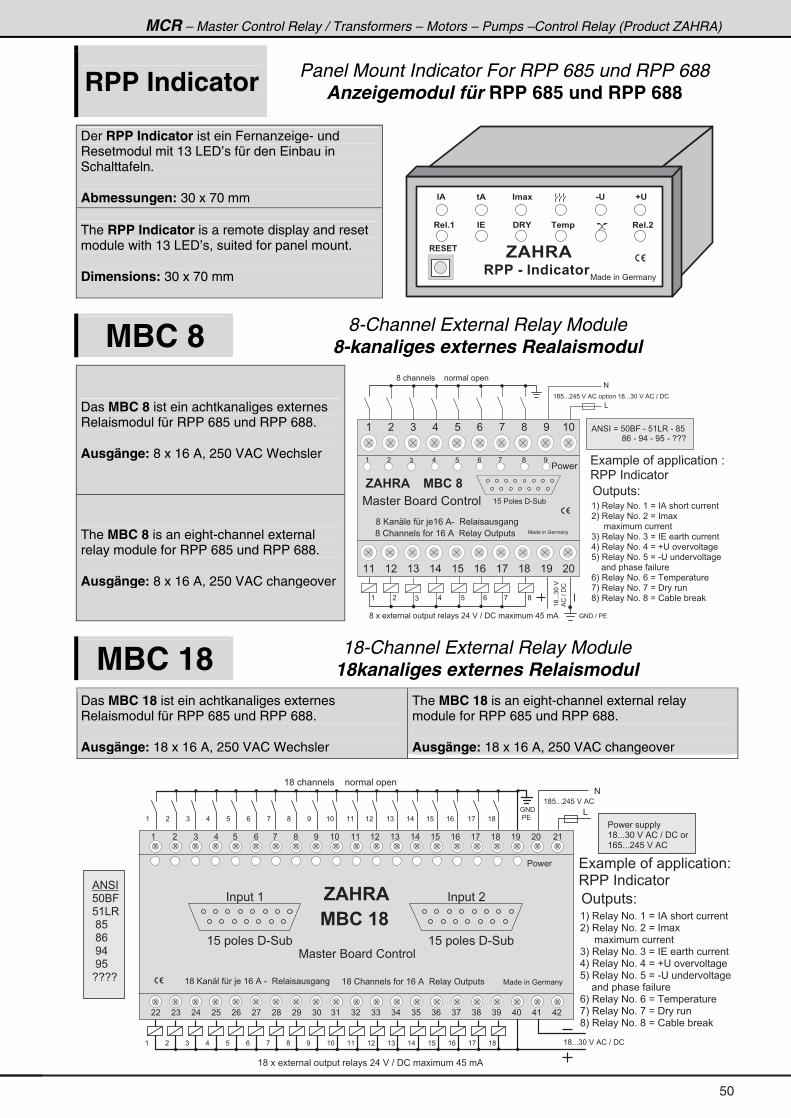
MCR – Master Control Relay / Transformers – Motors – Pumps –Control Relay (Product ZAHRA)
RPP Indicator Panel Mount Indicator For RPP 685 und RPP 688 Anzeigemodul für RPP 685 und RPP 688
Der RPP Indicator ist ein Fernanzeige- und Resetmodul mit 13 LED’s für den Einbau in Schalttafeln. Abmessungen: 30 x 70 mm
The RPP Indicator is a remote display and reset module with 13 LED’s, suited for panel mount. Dimensions: 30 x 70 mm 7 � � � � � � : � � � �
, $ � � $
� � � � & � " 4 B 2 � 6 3 1
� ! � ! �
" $ 6 $ " . � - & ' D '
� � � + � " ! � � J � � . � � � � + �
MBC 8 8-Channel External Relay Module 8-kanaliges externes Realaismodul
Das MBC 8 ist ein achtkanaliges externes Relaismodul für RPP 685 und RPP 688. Ausgänge: 8 x 16 A, 250 VAC Wechsler
The MBC 8 is an eight-channel external relay module for RPP 685 und RPP 688. Ausgänge: 8 x 16 A, 250 VAC changeover
( � ) . 8 / , ;
( I � 3 � � � � # � + � ( � B � � % � � � � � � � � � � �
� I � 3 � � � � # � + � � � B � � � � �
� � � � � � � � � � � � � � � � �
) I � 3 � � � � # � + � ) � B � � � � � � � � � � � � �
. I � 3 � � � � # � + � . � B � � � � � � � � � � �
8 I � 3 � � � � # � + � 8 � B � - � � � � � � � � � � �
� � � � � � � � � � � � � � � � �
/ I � 3 � � � � # � + � / � B � � � � � � � � �
, I � 3 � � � � # � + � , � B � � � � � �
; I � 3 � � � � # � + � ; � B � ! " � � � " � �
( ; 8 + + + � . 8 � $ � % ! � � � � � � � � ( ; + + + ) * � $ � % ! � ? � � !
#
&
(;+++)*�$�
%!�?��!
; � � � � � � � � � � � � � � � � � � � � � �
: # � � ? � � � �; � � � � � � � � � � � � � � � � � � � � � � � . � $ � ? � � ! � � � � � � � � . 8 � � %
( � ) . 8 / , ; < ( *
( ( ( � ( ) ( . ( 8 ( / ( , ( ; ( < � *
7 � � � � 6 � � � ! � � � � �
; � @ � S � � � � A � > � ( / � % - � � 3 � � � � � � � � �
; � ! � � � � � � � � � � ( / � % � � 3 � � � � ' � � � � � �
� � � �
% � � �
7 � � � � � � : � � � �
( 8 � � � � � � � � - 4 � "
, $ � � $
( � ) . 8 / , ; < � � � � � � � � � � � � � � � � � � � � 2
3 � � � � � � � � � �
' � � � � � � 2
% # 4 � � B � 8 * 6 9 � - � 8 ( & 3 � - � ; 8
� � � � � � � � � � � � � ; / � - � < . � - � < 8 � - � 5 5 5
MBC 18 18-Channel External Relay Module 18kanaliges externes Relaismodul
Das MBC 18 ist ein achtkanaliges externes Relaismodul für RPP 685 und RPP 688. Ausgänge: 18 x 16 A, 250 VAC Wechsler
The MBC 18 is an eight-channel external relay module for RPP 685 und RPP 688. Ausgänge: 18 x 16 A, 250 VAC changeover
( � ) . 8 / , ; < ( * ( ( ( � ( ) ( . ( 8 ( / ( , ( ; ( < � * � (
� � � ) � . � 8 � / � , � ; � < ) * ) ( ) � ) ) ) . ) 8 ) / ) , ) ; ) < . * . ( . �
7 � � � � 6 � � � ! � � � � �
( ; � @ � S � � � A � > � � ( / � % � - � � 3 � � � � � � � � � ( ; � ! � � � � � � � � � � ( / � % � � 3 � � � � ' � � � � � �
, $ � � $
% � � � �
7 � � � � � � : � � � �
: # �
� � � �
� � � � � � �
( 8 � � � � � � � � - 4 � "
( � ) . 8 / , ; < ( * ( ( ( � ( ) ( . ( 8 ( / ( , ( ;
� � � � � � (
( 8 � � � � � � � � - 4 � "
( � ) . 8 / , ; < ( * ( ( ( � ( ) ( . ( 8 ( / ( , ( ;
( ; 8 + + + � . 8 � $ � % !
( ; � � � � � � � � � � � � � � � � � � � � � �
� ( ; + + + ) * � $ � % ! � ? � � !
( ; � � � � � � � � � � � � � � � � � � � � � � � . � $ � ? � � ! � � � � � � � � . 8 � � %
#
&
� � � �
( I � 3 � � � � # � + � ( � B � � % � � � � � � � � � � �
� I � 3 � � � � # � + � � � B � � � � �
� � � � � � � � � � � � � � � � �
) I � 3 � � � � # � + � ) � B � � � � � � � � � � � � �
. I � 3 � � � � # � + � . � B � � � � � � � � � � �
8 I � 3 � � � � # � + � 8 � B � - � � � � � � � � � � �
� � � � � � � � � � � � � � � � �
/ I � 3 � � � � # � + � / � B � � � � � � � � �
, I � 3 � � � � # � + � , � B � � � � � �
; I � 3 � � � � # � + � ; � B � ! " � � � " � �
� � � � � � � � � � �
( ; + + + ) * � $ � % ! � ? � � ! � �
( / 8 + + + � . 8 � $ � % !
� � � � � � � � � � � � � � � � � � � 2
3 � � � � � � � � � �
' � � � � � � 2
% # 4 �
8 * 6 9
8 ( & 3
� ; 8
� ; /
� < .
� < 8
5 5 5 5
50
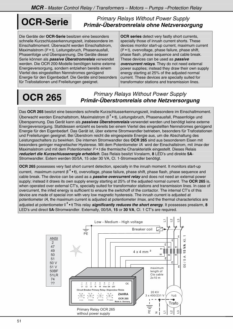
MCR – Master Control Relay / Transformers – Motors – Pumps –Protection Relay
OCR-Serie Primary Relays Without Power Supply Primär-Überstromrelais ohne Netzversorgung
Die Geräte der OCR-Serie besitzen eine besonders schnelle Kurzschlusserkennungszeit, insbesondere im Einschaltmoment. Überwacht werden Einschaltstrom, Maximalstrom (I² • t), Leitungsbruch, Phasenausfall, Phasenfolge und Überspannung. Die Geräte dieser Serie können als passive Überstromrelais verwendet werden. Die OCR 200-Modelle benötigen keine externe Energieversorgung, sondern entziehen bereits einem Viertel des eingestellten Nennstromes genügend Energie für den Eigenbedarf. Die Geräte sind besonders für Trafostationen und Freileitungen geeignet.
OCR series detect very fastly short currents, specially those of inrush current shorts. These devices monitor start-up current, maximum current (I² • t), overvoltage, phase failure, phase shift, phase flash, phase sequence and cable break. These devices can be used as passive overcurrent relays. They do not need external power supplies; instead they draw their own supply energy starting at 25% of the adjusted normal current. These devices are specially suited for transformator stations and transmission lines.
OCR 265 Primary Relays Without Power Supply Primär-Überstromrelais ohne Netzversorgung
Das OCR 265 besitzt eine besonders schnelle Kurzschlusserkennungszeit, insbesondere im Einschaltmoment. Überwacht werden Einschaltstrom, Maximalstrom (I
2 • t), Leitungsbruch, Phasenausfall, Phasenfolge und
Überspannung. Das Gerät kann als passives Überstromrelais verwendet werden und benötigt keine externe Energieversorgung. Stattdessen entzieht es bereits bei einem Viertel des eingestellten Nennstromes genügend Energie für den Eigenbedarf. Das Gerät ist, über externe Stromwandler betrieben, besonders für Trafostationen und Freileitungen geeignet. Bei Überstrom reicht die eingespeiste Energie aus, um die Abschaltung des Leistungsschalters zu bewirken. Die internen Stromwandler des OCR 265 sind aus besonderem Eisen mit besonders geringer magnetischer Hysterese. Mit dem Potentiometer IA wird der Einschaltstrom, mit Imax der Maximalstrom und mit dem Potentiometer I² • t die thermische Charakteristik eingestellt. Dieses Relais reduziert die Kurzschlussenergie erheblich. Das Relais besitzt Voralarm, 8 LED’s und direkte 5A-Stromwandler. Extern werden 00/5A, 15 oder 30 VA, Cl. 1-Stromwandler benötigt.
OCR 265 possesses very fast short current detection, specially in the inrush moment. It monitors start-up current, maximum current (I
2 • t), overvoltage, phase failure, phase shift, phase flash, phase sequence and
cable break. The device can be used as a passive overcurrent relay and does not need an external power supply; instead it draws its own supply energy starting at 25% of the adjusted normal current. The OCR 265 is, when operated over external CT’s, specially suited for transformator stations and transmission lines. In case of overcurrent, the infed energy is sufficient to ensure the switchoff of the contactor. The internal CT’s of this device are made of special iron with very low magnetic hysteresis. The inrush current is adjusted at potentiometer IA, the maximum current is adjusted at potentiometer Imax, and the thermal characteristics are adjusted at potentiometer I
2 • t This relay significantly reduces the short energy. It possesses prealarm, 8
LED’s und direct 5A-Stromwandler. Externally, 00/5A, 15 or 30 VA, Cl. 1 CT’s are required.
**�?�8�%������$��@�+�(
� � � � � � �
� � � � � � � � �
! � � � � " � � �
� � ( * � �
. � � � . � � � � Q
6 � � � � � � �
� �
&(
��
��
��
��
��
��
� �
� �
� �
� �
� �� �
&�
&)
&(
&�
&)
#
� � �
& � � � - � 7 � � � � � � - � 0 � � � � � � � � �
� * � @ $
) � � � . * * ? � ) ( � $ �
� � � � � 3 � � � � ' ! 3 � � / 8
� � � � � � � � � � � � � � � � � � �
% # 4 �
� � �
� . ,
� . <
� 8 *
� 8 (
8 * � $
8 ( � $
8 * 6 9
8 ( & 3
� , .
� 5 5
, $ � � $
� � 1 2 8 6 � � 1 � � < � 1 � � 1 . � 1 � � � � � � � & � � � C 3 4 2 6 � 8 1 � � � � � �
( �
" $ 6 $
� % � � E % F
�� �
� �
� � �
)
" . � -
. 8 /
% � B � � 4 � � � � 1 . � 4 �
# � � � � �
# � # � �
,
( �( �( �
;
� � � � L � � � E � � � F�
�� �
� �
� � �
� � � � � � � � E % F� �
��
��
� �
��
K 1 8
� % � E � � � F
�� �
� �
� � �
51

MCR – Master Control Relay / Transformers – Motors – Pumps –Control Relay (Product ZAHRA)
OCR 285 Primary Relays Without Power Supply Primär-Überstromrelais ohne Netzversorgung
������$�����$��*�+��
(��
(��
(��
*
�=8���Q
� ���������������(*��
0������� ����-�7��������� ���-�&������� ���H�.*+++�/*�01�I
!������2�4� �����������-�4� ��������
��-�'�������E�������F
� ���&� ���H��������
��I�%�������������� ���������������
��
��
��
��
��
��
��
��
��
��
��
��
�
.���(/�%�H#'I�'������3�� ��� ���(��&���=����������������'#�?�'99����%�����������
� ��
7 ������:�� ��
,$��$
#�����
#9�12811�46������
: 6;386��3:�1��8����
&(
&�
&)
�%
��
�%
�
�� �
#��
#�
��2�3��1��: 62;
4� �����������2�%�>��� "��� ����;����#��� ����� ��������� ��
4����������2�%�>��� "��� ����;����#��� ����� ��������� ��
4����������2�%�>��� "��� ����/����#��� ������� �����H� ���� ����I
����
3��+(3��+�
3��+)3��+.
�'#�O�'99
3��+(
3��+.
'99
'#
!����'99
#�
!����'#
3�� ��)
3������
!����'99
'99
3��+�
� ���������
9��+��
�'#�O�'99
'99
� ���������
!����'99
3��+(
3��+�
9��+�(
3 ���7�������
4�� ���7�������
��������������������
����������"� �+
��������������������
����������"� �+
�������������-��������
���� �� ��������������H�(8������I
�
3�� ���
/8
.
3�� ��(2
���� �� �����
4���������
3�� ���2
'�������
�E��������F�
3�� ��)2
%����������
3�� ��.2�
� ����� ��
3�� ��(
)�
(
3�� ��)
<;
,
3�� ��.
(;
(<
�*
3�� ��)�
����3������
!����'#
'#
3��+.
'�������3�� ��
(�
).
8/
,;
<(*
((
(�
()
(.
(8
(/
(,
(;
(<
�*
7 �����
:�� ��
��������E%F
� �
����E���F
%
*8
(.
�)
*)*
/�.
(�
(;
*)*
/
�.
(�
(;
,$��$
#�����
'�������3�� ���������������4�����
&�
&)�
��
&(
)8*
(*
.*
�*
)*
*8
(.
�)
�����L���E���F
�
�%�
�%�
�� ��
3��+)
'99
'#
3������
3��+(3��+�
����L���E���F
����E%F
����E%F
%
*.*
;)�
(/
�.
3��+.
��!
%#4��B��=�.,=�.<=��8*?�8(=��8*�$?�8(�$=8*:
�������������8(:=�8*�69=�8(�69=�,.=�,<�
Das OCR 285 unterscheidet sich vom OCR 265 durch 4 Ausgangsrelais (16 A Wechsler) mit den Funktionen: (1) Kurzschlusserkennung, (2) Überstrom, (3) Wiedereinschaltung, (4) Fehlerstrom
The OCR 285 differs from OCR 265 by the presence of 4 output relays (16 A changeover) with the dedicated functions: (1) short current, (2) overcurrent, (3) autorecloser, (4) earth fault
52
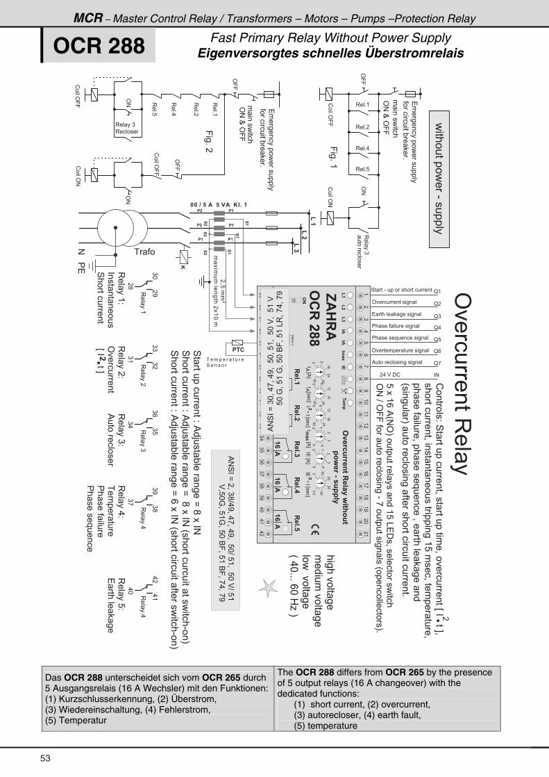
MCR – Master Control Relay / Transformers – Motors – Pumps –Protection Relay
OCR 288 Fast Primary Relay Without Power Supply Eigenversorgtes schnelles Überstromrelais
� � � � � � � � � � � � � �
' � � � � � � � � � � � �
4 � � � - � � � � � � � � � � � � � � � �
� � � � � � � � � � � � � � � �
� � � � � � � � � � � � � � � � � � �
' � � � � � � � � � � � � � � �
% � � � � � � � � � � � � � � � � � �
N (
� � � � � � $ � � � � � $ � � * � + � �
(��
(��
(��
*
�=8���Q
� ���������������(*��
� �
� �
� �
� �
� �
� �
��
��
��
��
��
��
� � � � � � � �
4 � � � �
4� �����������2�%�>��� "��� ����B�;����#
4����������2�%�>��� "��� ����B��;����#�H������������ ��������-��I
4����������2�%�>��� "��� ����B�/����#�H������������ ����������-��I
3�� ��(
�<
�
3�� ��(2
���� �� ������
4���������
3�� ���2
'�������
�E��������F�
3�� ��)2
%����������
3�� ��.2�
����� ���
�� ���� ����
�� �����������
3�� ��82�
� ����� ��
)*
�;
3�� ���
)�
))
)(
3�� ��)
)8
)/
).
3�� ��.
);
)<
),
3�� ��.
.(
.�
.*
'99
!����'99
3 � � + (
3 � � + �
3 � � + .
3 � � + 8
!����'#
'#
9��+�(
3��+(
3��+8
3��+.
'99
'#
!����'99
'#
!����'#
3 � � � � )
3 � � � � � �
!����'99
'99
3��+�
9��+��
�������� ���
���������� ��
�������� ���
H�.*+++�/*�01�I
!������2�4� ����������=��� ��������
�=���������E�������F=�
����������=����� �� ��������������(8�����=������ ���=�
�� ���� ����=��� ������������=�� ����� ��� ���
H������ I� ������������� ���������������������+�
8���(/�%H#'I���������� ��� ���(8�&���=����������������
'#�?�'99���� �������������-�,������������ ���H�������������I+
� � �
� � �
�
� . � $ � � !
N �
N )
N .
N 8
N /
N ,
� #
�������������-��������
�'#�O�'99
� ���������
�'#�O�'99
� ���������
3�� ��)�
����������
��������������������
����������"� �+
��������������������
����������"� �+
'�������3�� ��
(�
).
8/
,;
<(*
((
(�
()
(.
(8
(/
(,
(;
(<
�*
�(
��
�)
�.
�8
�/
�,
�;
�<
)*
)(
)�
))
).
)8
)/
),
);
)<
.*
.(
.�
(�
(�
(�
"$
6$
,$��$
#����
#9�12811�46�������: 6;386�
�3:�1�&��8����
���+�
���+�
� $
� $
���+�
� $
���+�
� $
���+�
� $
".�-
"!
��.�
7 �����
:�� ��
��������E%F
.�-
����E���F
%
*8
(.
�)
*)*
/�.
(�
(;
*)*
/
�.
(�
(;
)8*
(*
.*
�*
)*
*8
(.
�)
�����L���E���F
�
#��
��2�3��1��: 62;
����L���E���F
����E%F
����E%F
%
*.*
;)�
(/
�.
#�
#��
%#4��B�)*=�.,=�.<=��8*=�8(=��8*�$=��8(�$
������������8*�:=�8(�:=�8*�69=�8(�&3=�,.=�,<�
%#4��B��=�);?.<=�.,=�.<=��8*?�8(=��8*�$?�8(
�������������$=8*:=�8(:=�8*�69=�8(�69=�,.=�,<�
Das OCR 288 unterscheidet sich vom OCR 265 durch 5 Ausgangsrelais (16 A Wechsler) mit den Funktionen: (1) Kurzschlusserkennung, (2) Überstrom, (3) Wiedereinschaltung, (4) Fehlerstrom, (5) Temperatur
The OCR 288 differs from OCR 265 by the presence of 5 output relays (16 A changeover) with the dedicated functions:
(1) short current, (2) overcurrent, (3) autorecloser, (4) earth fault, (5) temperature
53
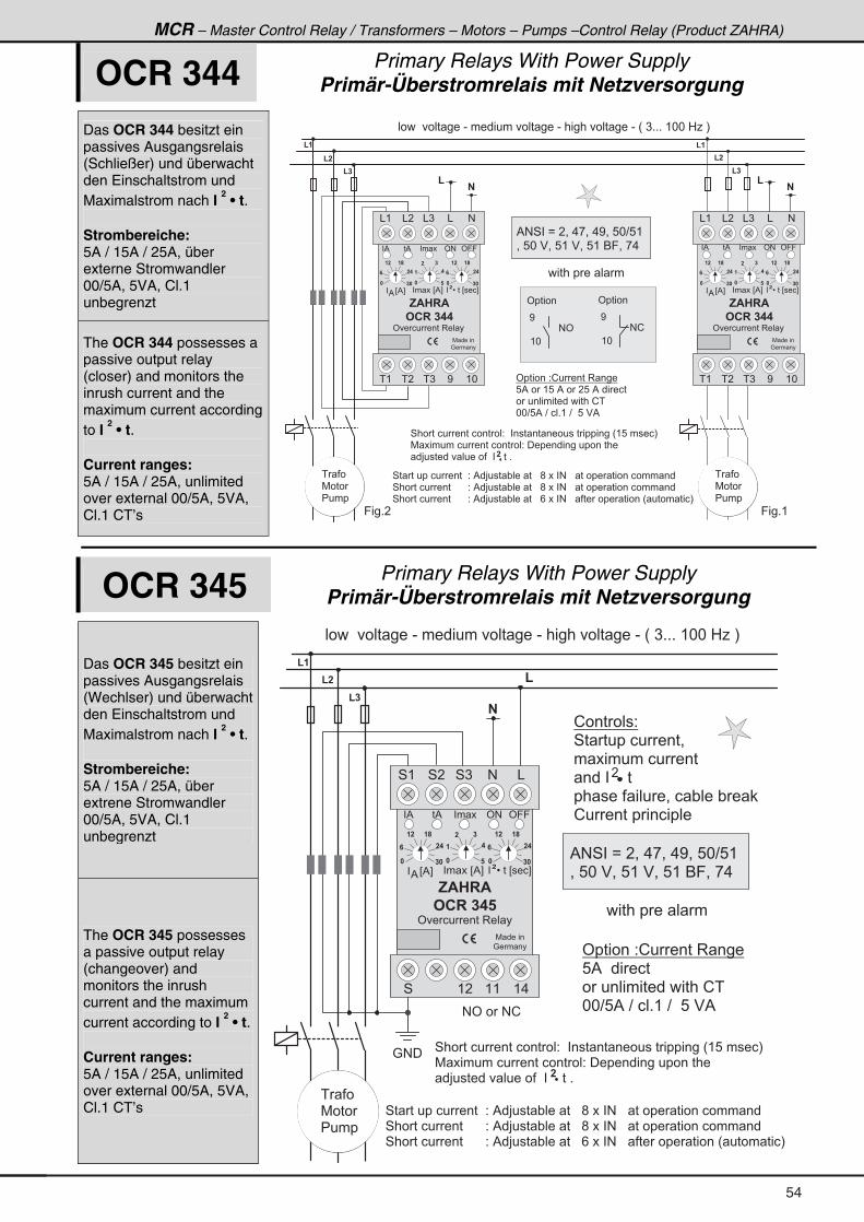
MCR – Master Control Relay / Transformers – Motors – Pumps –Control Relay (Product ZAHRA)
OCR 344 Primary Relays With Power Supply Primär-Überstromrelais mit Netzversorgung
Das OCR 344 besitzt ein passives Ausgangsrelais (Schließer) und überwacht den Einschaltstrom und Maximalstrom nach I
2 • t.
Strombereiche: 5A / 15A / 25A, über externe Stromwandler 00/5A, 5VA, Cl.1 unbegrenzt
The OCR 344 possesses a passive output relay (closer) and monitors the inrush current and the maximum current according to I
2 • t.
Current ranges: 5A / 15A / 25A, unlimited over external 00/5A, 5VA, Cl.1 CT’s
4 � � � � � � � � � � � � � 2 � % � > � � � " � � � � � � � ; � � � � # � � � � � � � � � � � � � � � � � � �
4 � � � � � � � � � � � � � � � 2 � % � > � � � " � � � � � � � ; � � � � # � � � � � � � � � � � � � � � � � � �
4 � � � � � � � � � � � � � � � 2 � % � > � � � " � � � � � � � / � � � � # � � � � � � � � � � � � � � � H � � � � � � � I
�
<
( *
4 � � � � � � � � � � � � � � � � 2 � � � � � � � � � � � � � � � � � � � � � � H ( 8 � � � � � I
7 � � � � � � � � � � � � � � � � � � 2 � � � � � � � � � � � � � � � � � � � �
� > � � � � � � � � � � � � � � � � � � � � + �
( �
( �
( �
( �
( �
9 � � + �
( �
�
(
' � � � � � � 2 ! � � � � � 3 � � � �
8 % � � � ( 8 � % � � � � 8 � % � � � � � � �
� � � � � � � � � � � � � � � � � ! �
* * ? 8 % � ? � � � + ( � ? � � 8 � $ %
' � � � � �
� � � � � � � � � � � � - � � � � � � � � � � � � � � - � � � � � � � � � � � � - � H � ) + + + � ( * * � 0 1 � I
# '
<
( *
' � � � � �
# !
9 � � + (
� � �
7 � � �
� � � �
� � �
7 � � �
� � � �
% # 4 � � B � � = � . , = � . < = � 8 * ? 8 (
= � 8 * � $ = � 8 ( � $ = � 8 ( � 6 9 = � , . �
, $ � � $
# � � � � � �
7 � � � � �
: � � � �
' � � � � � � � 3 � � �
& ( & ) && � #
� ( � ) < ( *� �
� � � � E % F%
� � �
� �
� � �
� � � � E % F
� �
� �
� �
� � �
� �
� � �
� � � L � � � E � � � F�
� � � � � � � � � �
, $ � � $
# � � � � � �
7 � � � � �
: � � � �
' � � � � � � � 3 � � �
& ( & ) && � #
� ( � ) < ( *� �
� � � � E % F%
� � �
� �
� � �
� � � � E % F
� �
� �
� �
� � �
� �
� � �
� � � L � � � E � � � F�
�
(
' #� % ' 9 9� % � � � ' #� % ' 9 9� % � � �
OCR 345 Primary Relays With Power Supply Primär-Überstromrelais mit Netzversorgung
Das OCR 345 besitzt ein passives Ausgangsrelais (Wechlser) und überwacht den Einschaltstrom und Maximalstrom nach I
2 • t.
Strombereiche: 5A / 15A / 25A, über extrene Stromwandler 00/5A, 5VA, Cl.1 unbegrenzt
The OCR 345 possesses a passive output relay (changeover) and monitors the inrush current and the maximum current according to I
2 • t.
Current ranges: 5A / 15A / 25A, unlimited over external 00/5A, 5VA, Cl.1 CT’s
! � � � � � � 2
4 � � � � � � � � � � =
� � � � � � � � � � � � �
� � � � � � � � � �
� � � � � � � � � � = � � " � � � " �
! � � � � � � � � � � � � �
4 � � � � � � � � � � � � � 2 � % � > � � � " � � � � � � � ; � � � � # � � � � � � � � � � � � � � � � � � �
4 � � � � � � � � � � � � � � � 2 � % � > � � � " � � � � � � � ; � � � � # � � � � � � � � � � � � � � � � � � �
4 � � � � � � � � � � � � � � � 2 � % � > � � � " � � � � � � � / � � � � # � � � � � � � � � � � � � � � H � � � � � � � I
�
4 � � � � � � � � � � � � � � � � 2 � � � � � � � � � � � � � � � � � � � � � � H ( 8 � � � � � I
7 � � � � � � � � � � � � � � � � � � 2 � � � � � � � � � � � � � � � � � � � �
� > � � � � � � � � � � � � � � � � � � � � � + �
�
( �
( �
( �
�
(
' #
, $ � � $ �
# � � � � � �
7 � � � � �
: � � � �
' � � � � � � � 3 � � �
4 ( 4 ) #4 � &
4 ( � ( ( ( .
� %
� � � � E % F%
� � �
� �
� � �
� � � � E % F
� �
� �
� �
� � �
� �
� � �
� � � L � � � E � � � F�
' 9 9� % � � �
' � � � � � � 2 ! � � � � � 3 � � � �
8 % � � � � � � � �
� � � � � � � � � � � � � � � � � ! �
* * ? 8 % � ? � � � + ( � ? � � 8 � $ %
: # �
# ' � � � # !
� � � � � � � � � � � � - � � � � � � � � � � � � � � - � � � � � � � � � � � � - � H � ) + + + � ( * * � 0 1 � I
� � �
7 � � �
� � � �
� � � � � � � � � �
% # 4 � � B � � = � . , = � . < = � 8 * ? 8 (
= � 8 * � $ = � 8 ( � $ = � 8 ( � 6 9 = � , . �
54
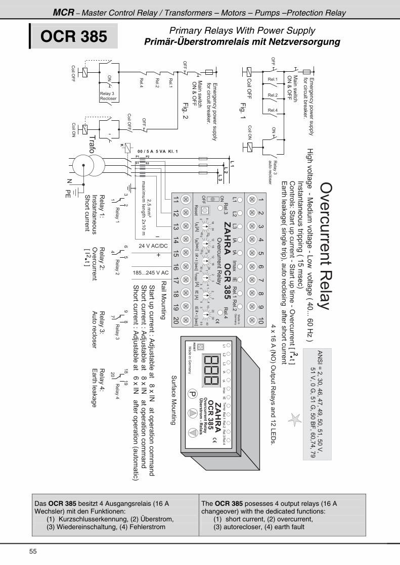
MCR – Master Control Relay / Transformers – Motors – Pumps –Protection Relay
OCR 385 Primary Relays With Power Supply Primär-Überstromrelais mit Netzversorgung
� � � � � � $ � � � � � $ � � * � + � �
(��
(��
(��
*
�=8���Q
� ���������������(*��
� �� �
� � � �
� ��
7 ������:�� ��
,$��$
#�����
#9�12811�46������
M@�1�613.�&����� �
&(
&�
&)
�%
��
�%
�
�� �
4� �����������2�%�>��� "��� ����;����#��� ����� ��������� ��
4����������2�%�>��� "��� ����;����#��� ����� ��������� ��
4����������2�%�>��� "��� ����/����#��� ������� �����H ���� ���I
����
3��+(3��+�
3��+)3��+.
4�� ���7�������
�!�!�
� . � $ � % ! ? � !
( ; 8 + + + � . 8 � $ � % !
0������� ����-�7��������� ���-�&������� ���H�.*+++�/*�01�I
!������2�4� �����������-�4� ��������
��-�'�������E�������F
� ����� ��H�����������I=� �������������� ���������������
�
.���(/�%�H#'I�'������3�� ��� ���(��&���+
���� �� ��������������H�(8�����I
�'#�O�'99
3��+(
3��+.
'99
'#
!����'99
!����'#
3 � � � � )
3 � � � � � �
!����'99
'99
3��+�
7 ���������
9��+��
'99
7 ���������
9��+�(
��������������������
����������"� �+
��������������������
����������"� �+
3 ���7�������
�
3�� ���
.
3�� ��(2
���� �� �����
4���������
3�� ���2
'�������
�E��������F�
3�� ��)2
%����������
)�
3�� ��)
,
3�� ��.
�*
(
/8
<;
(;
(<
3�� ��.2�
� ����� ��
3�� ��(
�'#�O�'99
!����'99
3�� ��)�
����������
3 � � + (
3 � � + �
3 � � + .
!����'#
'#
'�������3�� ��
%#4��B��=�)*=�./=�.,=�.<=�8*=�8(=�8*�$=
����������8(�$=�*�:=�8(�:=�8*�69=�/*=,.=�,<
(�
).
8/
,;
<(*
((
(�
()
(.
(8
(/
(,
(;
(<
�*
7 �����
:�� ��
��������E%F
� �
����E���F
%
*8
(.
�)
*)*
/�.
(�
(;
*)*
/
�.
(�
(;
,$��$
#�����
'�������3�� ��
&�
&)�
��
&(
)8*
(*
.*
�*
)*
*8
(.
�)
�����L���E���F
�
�%�
�%�
�� ��
3��+)
'99
'#
3����
3��+(3��+�
����L���E���F
����E%F
����E%F
%
*.*
;)�
(/
�.
3��+.
#��
Das OCR 385 besitzt 4 Ausgangsrelais (16 A Wechsler) mit den Funktionen:
(1) Kurzschlusserkennung, (2) Überstrom, (3) Wiedereinschaltung, (4) Fehlerstrom
The OCR 385 posesses 4 output relays (16 A changeover) with the dedicated functions:
(1) short current, (2) overcurrent, (3) autorecloser, (4) earth fault
55
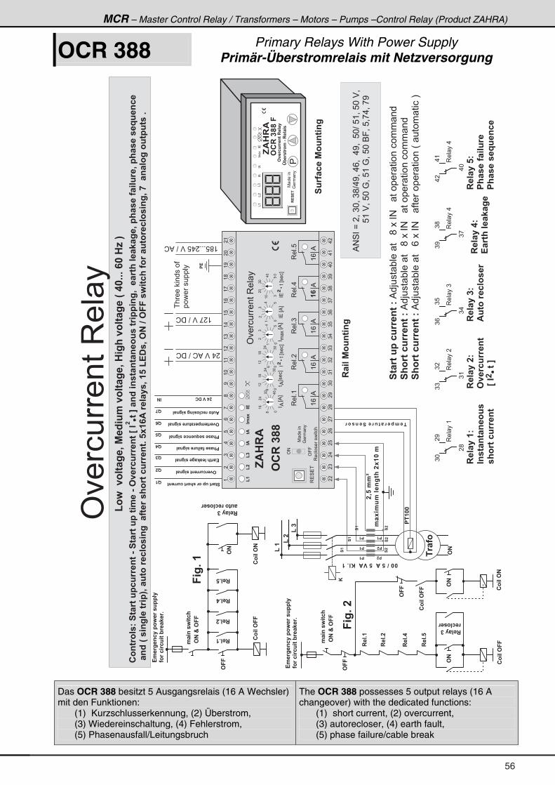
MCR – Master Control Relay / Transformers – Motors – Pumps –Control Relay (Product ZAHRA)
OCR 388 Primary Relays With Power Supply Primär-Überstromrelais mit Netzversorgung
������$�����$��*�+��
(��
(��
(��
�0��..K
.�- .8.���4=6;��-���.
��
��
��
��
��
��
��
��
��
��
��
��
��.��1�681����4�31
�1��3
(3:��93�6�=�0�%�B 8.�93�6�=�0�� =;�93�6�=��H���+++� ���E�I
�34613��7��6�16�8�2811�46�&��6�16�8��6 .��&�#9�12811�46�>�"���6�?��4B� 4�6�46�4�38��61 �� 4=0����16;����<�=�0��;������ �81�0��;������L8�42�
��4B�H�� 4=���61 �I0��863�1�2�3� 4=����6�1��;316�2811�46+��-� $�1�����0����(!��0�#���#����: 62;��31��8631�2�3� 4=0�����4��3=�386�86��+
�
�����
�!
(;8+++�.8�$�?�%!
(�,�$�?��!
����� �������
�����������
�.�$�%!�?��!
7 ������
:�� ��
,$��$
#������
�!�!�
#9�12811�46������
M@�1�613.�&����� �
&(
&�
&)
�%
�%
�
�81��2��%3846 4=
�#��N�#��
���+�
���+�
���+�
#�� #�
�3 ��#��
#�
�3 ��#�
�������
1�2�3��1
�3 ��#��
#��
���+�
.� 4��: 62;
� =+��
3�� ��(
�<
�
�������7
#9�12811�46�
�>�"����6�?�
�������7
$863�1�2�3��1
�������7�
�;������ �81�
�;������L8�42�
�������7�
!�16;����<�=�
)*
�;
3�� ���
)�
))
)(
3�� ��)
)8
)/
).
3�� ��.
);
)<
),
3�� ��.
.(
.�
.*
�6�16�8��2811�46�7�%�>��� "��� ����;����#��� ����� ��������� ��
�;316�2811�46�7�%�>��� "��� ����;����#��� ����� ��������� ��
�;316�2811�46�7�%�>��� "��� ����/����#��� ������� �����H� ���� ����I
�#��N�#��
#��
.� 4��: 62;
�3 ��#��
��������
�863�1�2�3��1
���+�
���+�
���+�
���+�
�3 ��#�
#�
� =+��
�� ��%3846 4=
�� �
��
!�16;����<�=��� =4��
#9�12811�46�� =4��
�6�16�8��31��;316�2811�46
�;������ �81��� =4��
�;������L8�42��� =4��
#9�16�.��1�681��� =4��
$863�1�2�3� 4=�� =4��
F�
�������
F�
F�
F�
F�
F
F�
"�
!.�1=�42���3:�1��8����
�31�2 128 6�@1��<�1+
!.�1=�42���3:�1��8����
�31�2 128 6�@1��<�1+
�������7
"4�6�46�4�38��
�;316�2811�46�
'�������3�� �
(�
).
8/
,;
<(*
((
(�
()
(.
(8
(/
(,
(;
(<
�*
�(
��
�)
�.
�8
�/
�,
�;
�<
)*
)(
)�
))
).
)8
)/
),
);
)<
.*
.(
.�
(�
(�
(�
"$
6$
,$��$
#����
'�������3�� �
3��+.
3��+8
� %
(/%
3��+)
(/%
3��+�
(/%
3��+(
(/%
".�-
"!
7 �����
:�� ��
��������E%F
� �
����E���F
%
*8
(.
�)
*)*
/�.
(�
(;
*)*
/
�.
(�
(;
)8*
(*
.*
�*
)*
*8
(.
�)
�����L���E���F
�
����L���E���F
����E%F
����E%F
%
*.*
;)�
(/
�.
3�4��
'99
'#
3�������������
*
#�
%#4��B��=�)*=�);?.<=�./=��.<=��8*?�8(=�8*�$=
������������8(�$=�8*�:=�8(�:=�8*�69=�8=,.=�,<
Das OCR 388 besitzt 5 Ausgangsrelais (16 A Wechsler) mit den Funktionen:
(1) Kurzschlusserkennung, (2) Überstrom, (3) Wiedereinschaltung, (4) Fehlerstrom, (5) Phasenausfall/Leitungsbruch
The OCR 388 possesses 5 output relays (16 A changeover) with the dedicated functions:
(1) short current, (2) overcurrent, (3) autorecloser, (4) earth fault, (5) phase failure/cable break
56
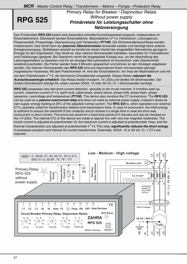
MCR – Master Control Relay / Transformers – Motors – Pumps –Protection Relay
RPG 525 Primary Relay for Breaker / Disjoncteur Relais
Without power supply Primärrelais für Leistungsschalter ohne
Netzversorgung
Das Primärrelais RPG 525 besitzt eine besonders schnelle Kurzschlusserkennungszeit, insbesondere im Einschaltmoment. Überwacht werden Einschaltstrom, Maximalstrom (I² • t), Fehlerstrom, Leitungsbruch, Phasenausfall, Phasenfolge, Überspannung und Temperatur (PT100). Die Stromwandleranschlüsse werden mitüberwacht. Das Gerät kann als passives Überstromrelais verwendet werden und benötigt keine externe Energieversorgung. Stattdessen entzieht es bereits bei einem Viertel des eingestellten Nennstroms genügend Energie für den Eigenbedarf. Das Gerät ist, über externe Stromwandler betrieben, besonders für Trafostationen und Freileitungen geeignet. Bei Überstrom reicht die eingespeiste Energie aus, um die Abschaltung des Leistungsschalters zu bewirken und ihn ein einziges Mal automatisch im Kurzschluß- oder Überstromfall wiedereinzuschalten. Die Fehler werden feste 5 Minuten gespeichert und können an den Anzeigen abgelesen werden. Die internen Stromwandler des RPG 525 sind aus besonderem Eisen mit besonders geringer magnetischer Hysterese. Mit dem Potentiometer IA wird der Einschaltstrom, mit Imax der Maximalstrom und mit mit dem Potentiometer I
2 • t die thermische Charakteristik eingestellt. Dieses Relais reduziert die
Kurzschlussenergie erheblich. Das Relais besitzt Voralarm, 14 LEDs und direkte 5A-Stromwandler. Der direkte Strombereich beträgt 5A, extern werden 00/5A, 15 oder 30 VA, Cl. 1-Stromwandler benötigt.
RPG 525 possesses very fast short current detection, specially in the inrush moment. It monitors start-up current, maximum current (I² • t), earth fault, cable break, phase failure, phase shift, phase flash, phase sequence, overvoltage and temperature (PT100). The device also monitors the CT connections. The RPG 525 can be used as a passive overcurrent relay and does not need an external power supply; instead it draws its own supply energy starting at 25% of the adjusted normal current. The RPG 525 is, when operated over external CT’s, specially suited for transformator stations and transmission lines. In case of overcurrent, the infed energy is sufficient to ensure the switchoff of the contactor and to reclose it a single time in case the error was overcurrent or short current. The errors are saved for a fixed time period of 5 minutes and can be checked on the 14 LEDs. The internal CTs of this device are made of special iron with very low magnetic hysteresis. The inrush current is adjusted at potentiometer IA, the maximum current is adjusted at potentiometer Imax, and the thermal characteristics are adjusted at potentiometer I
2 • t. This relay significantly reduces the short energy.
It possesses prealarm and internal 5A current transformers. Externally, 00/5A, 15 or 30 VA, Cl. 1 CT’s are required.
, $ � � $
� � 1 2 8 6 � � 1 � � < � 1 � � 1 . � 1 � � � � � � � & � � � C 3 4 2 6 � 8 1 � � � � � �
( �
" $ 6 $
� � � � � � � � E % F� �� % � � E � � � F� % � � E % F
�� �
� �
� � �
�� �
� �
� � �
��
��
� �
)
" . � -
. 8
� � . �
/
% � B � � 4 � � � � 1 . � 4 �
$863&���2�3��1
� � � � � � �
**�?�8�%������$��@�+�(
. � - . 8 . �
� � 4 = 6 ; � 3 �
� 6 � � 2 � @ � � �
� - � � � .
� � - � � � . . K
� 1 � � < � 1 � 2 3 �
3 � 4 � �
� ! � � � � 8 6 6 3 4
# � # � �
,
( �( �( �
; < ( *
" � !
( (
� !
!-6�14��
�����6
( �
$ 8 6 3 � � � 2 � 3 � � 1
(�
��
��
��
��
��
��
� �
� �
� �
� �
� �� �
(�
(�
(�
(�
(�
�
� � �
! � 1 6 ; � ( � � < � = �
��.��1�681�
��34613�
#4��6 .�
( 3 : � & � % � B 8 . � & � � = ; � 9 3 � 6 � = �
� � � * � � � � � � � �
������
� � � � � 3 � � � �
3 � : � 8 � 8
� � � � � � � �
� � � � � � � � � � �
��
��
� �
� � � � � � E % F� � � � L � � � E � � � F�
�� �
� �
� � �
% # 4 � � B � � = � ) ; ? . < = � . , = � . < = � 8 * ? � 8 ( = � 8 * � $ ? � 8 ( $ = �
� � � � � � � � � � � � 8 * : ? � 8 ( � : = � 8 * � 6 9 = � , . = � , < � - � 5 5 5
�!
57
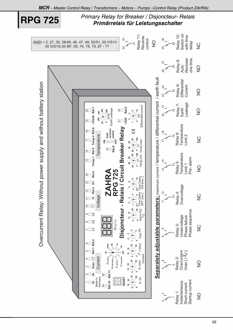
MCR – Master Control Relay / Transformers – Motors – Pumps –Control Relay (Product ZAHRA)
RPG 725 Primary Relay for Breaker / Disjoncteur- Relais Primärrelais für Leistungsschalter
,$��$
� �C3426�81�&����� ���� 128 6��1��<�1������
(�
"$
6$
��������E%F
� �
%����EJF
���
����� �
'99�E���+F
���
����� �
'#�E���++F
�%��E���F
����L���E���F
�
�%��E%F
���
��
�
��
���
��
��
�
���
��
��
�
��
��
��
���
���
��
��
�
��
��
�0�
��
�
�
�0�
���
��
�
��
�
�
����+����
���
��
�
��
�
�
E%F
��������� �������
)
".�-
, (�
;
(�
<(*
'&
((
'D
(�
(�
(8
��.�+�
.(<
"�!�16;
8
���+�
/
���+�
()
���+�
���+�
(,
��.�+�
(;
���+
(.
���+�
�*
���+�
�(
"�� ��+
��
���+
� ���&� ��
���
��
���
���
���
�
E�%F
(/
!����
$��� ��
����� ���
!
����+� ��
!��
��
��
�
)
�
3�� ���2
'�������
�� ��E��������F�
3�� ��)2
������� ��
�� ���� ����
�� �����������
3�� ��82�
����� ���
&��
���(
��-� � �
�
(
/8
.
<;
,
(�
((
(*
(8
(.
()
3�� ��(2
���� �� ������
4���������
4� ����������
7 �����
�:�� ��
�!�!�
#��
#�
$863�
1�2�3��1
�: 62;
!����
�
�)
���+�
(*������
3�� ��.2
'���� ��
3�� ��/2�
����� ���
&��
����
(;
(,
(/
3�� ��,2�
� ��
&� ��
�(
�*
(<
3�� ��;2�
��������� �
!����
�.
�)
��
3�� ��<2�
%���
3������
�������
�
�,
�/
�8
#'
#'
#!
#!
#'
#!
#'
#'
#'
"$
".�-
"�
D'
'�
&'
�����6��3 46
����268��
�����6��3 46
����268��
'�������3�� �2�C������������������� �����������" ������� ����
�������
����1�6�����BC8�6�@�����1�.�6�1�7�� ���
���������?������ ����?���������� ���������?�� ���� ����
3�� ��(*2�
4��������
��������
�
��� �
)*
�<
�;
#!
�.
���+��
�8
���+��
3�� ��((2�
3����
������
))
)�
)(
#'% # 4 � � B � � = � � , = � ) * = � ) ; ? . < = � . / = � . , = � . < = � 8 * ? 8 ( = � 8 * � $ ? 8 ( $
� � � � � � � � � � � � 8 * � : ? 8 ( : = 8 * � 6 9 = � 8 < = � , . = � , ; = � , < = � ; , � - � 5 5
58
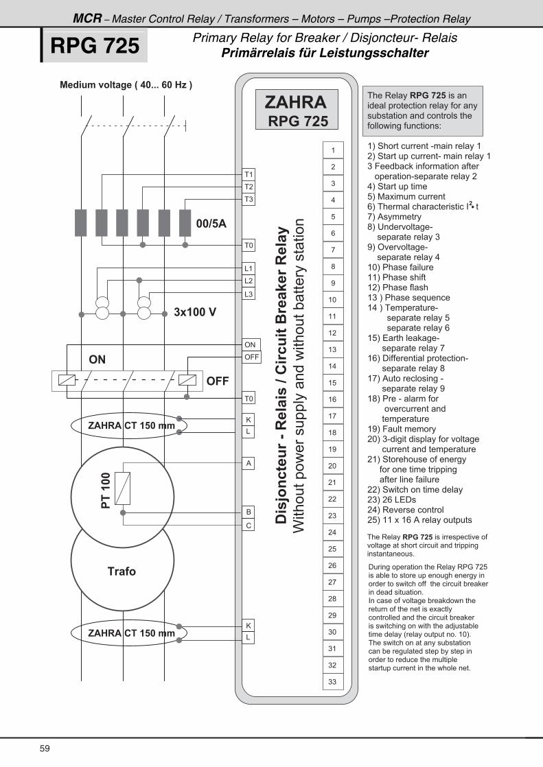
MCR – Master Control Relay / Transformers – Motors – Pumps –Protection Relay
RPG 725 Primary Relay for Breaker / Disjoncteur- Relais Primärrelais für Leistungsschalter
� (
� �
� )
� *
& (
& �
& )
%
6
!
' #
' 9 9
� *
@
&
� % � B 8 . � 9 3 � 6 � = � � H � � � + + + � � � � E � I
� , $ � � $ � � � � � � � � . .
� , $ � � $ � � � � � � � � . .
� � 1 � � 3
� - � � � � �
� � � $
C������������������� �����������" ������� ����
� � � � 3 � � � � � � � � � � � � � � � �
� � � � � � � � � � � � � � � � � � � � � � � �
� � " � � � � � � � � � � � � � � � � � � � � � �
� � � � � � � � � � � � � � � � � � � 2
( I � 4 � � � � � � � � � � - � � � � � � � � (
� I � 4 � � � � � � � � � � � - � � � � � � � � � (
) � 9 � � � " � � � � � � � � � � � � � � � �
� � � � � � � � � � - � � � � � � � � � � �
. I � 4 � � � � � � � � � �
8 I � 7 � � � � � � � � � � �
/ I � � � � � � � � � � � � � � � � � � � � � � �
, I � % � � � � � � �
; I � � � � � � � � � � -
� � � � � � � � � � � � � � )
< I � ' � � � � � � -
� � � � � � � � � � � � � � .
( * I � � � � � � � � � � �
( ( I � � � � � � � � � � �
( � I � � � � � � � � � �
( ) � I � � � � � � � � � � � � � �
( . � I � � � � � � � � � -
� � � � � � � � � � � � � � � � � � 8
� � � � � � � � � � � � � � � � � � /
( 8 I � � � � � � � � � -
� � � � � � � � � � � � � � � � ,
( / I � � � � � � � � � � � � � � � � � � � � � -
� � � � � � � � � � � � � � � � ;
( , I � % � � � � � � � � � � � � � -
� � � � � � � � � � � � � � � � <
( ; I � � � � - � � � � � � �
� � � � � � � � � � � � � � � � � �
� � � � � � � � � � � � � �
( < I � 9 � � � � � � � � �
� * I � ) - � � � � � � � � � � � � � � � � � � � � �
� � � � � � � � � � � � � � � � � � � � � � �
� ( I � 4 � � � � � � � � � � � � � � � � �
� � � � � � � � � � � � � � � � � � � � � � � �
� � � � � � � � � � � � � � � � � � �
� � I � 4 � � � � � � � � � � � � � � � � � �
� ) I � � / � & � � �
� . I � 3 � � � � � � � � � � �
� 8 I � ( ( � � � ( / � % � � � � � � � � � � � �
�
� � � � 3 � � � � � � � � � � � � � � � � � � � � � � � � � � �
� � � � � � � � � � � � � � � � � � � � � � � � � � � � � �
� � � � � � � � � � � + �
# �
# � �
� � � � � � � � � � � � � � � � � � 3 � � � � 3 � : � , � 8
� � � " � � � � � � � � � � � � � � � � � � � � � � � � � � � � �
� � � � � � � � � � � � � � � � � � � � � � � � � � � � � � " � �
� � � � � � � � � � � � � � � +
� � � � � � � � � � � � � � � � " � � � � � � � � �
� � � � � � � � � � � � � � � � � � � � � � � � � �
� � � � � � � � � � � � � � � � � � � � � � � � " � � �
� � � � � � � � � � � � � � � � � � � � � � � � � � > � � � " � � �
� � � � � � � � � � H � � � � � � � � � � � � � + � ( * I +
� � � � � � � � � � � � � � � � � � � � � " � � � � � � �
� � � " � � � � � � � � � � � � � � � " � � � � � � � � �
� � � � � � � � � � � � � � � � � � � � � � � � � �
� � � � � � � � � � � � � � � � � � � � � � � � � � � � +
������
(
�
)
.
8
/
,
;
<
( *
( (
( �
( )
( .
( 8
( /
( ,
( ;
( <
� *
� (
� �
� )
� .
� 8
� /
� ,
� ;
� <
) *
, $ � � $
� � � � � � �
� �C3426�81�&����� ���� 128 6��1��<�1������
) (
) �
) )
@
&
59
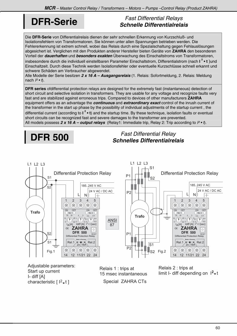
MCR – Master Control Relay / Transformers – Motors – Pumps –Control Relay (Product ZAHRA)
DFR-Serie Fast Differential Relays Schnelle Differentialrelais
Die DFR-Serie von Differentialrelais dienen der sehr schnellen Erkennung von Kurzschluß- und Isolationsfehlern von Transformatoren. Sie können unter allen Spannungen betrieben werden. Die Fehlererkennung ist extrem schnell, wobei das Relais durch eine Spezialschaltung gegen Fehlauslösungen abgesichert ist. Verglichen mit den Produkten anderer Hersteller bieten Geräte von ZAHRA den besonderen Vorteil der dauerhaften und besonders exakten Überwachung des Einschaltstroms von Transformatoren, insbesondere durch die individuell einstellbaren Parameter Einschaltstrom, Differentialstrom (nach I
2 • t )und
Einschaltzeit. Durch diese Technik werden Isolationsfehler oder eventuelle Kurzschlüsse schnell erkannt und schwere Schäden am Verbraucher abgewendet. Alle Modelle der Serie besitzen 2 x 16 A – Ausgangsrelais (1. Relais: Sofortmeldung, 2. Relais: Meldung nach I² • t).
DFR series ofdifferential protection relays are designed for the extremely fast (instantaneous) detection of short circuit and selective isolation in transformers. They are usable for any voltage and recognize faults very fast and are stabilized against erroneous trips. Compared to devices of other manufacturers ZAHRA equipment offers as an advantage the continuous and extraordinary exact control of the inrush current of the transformer in the start up phase by the possibility of individual adjustments of the startup current , the differential current (according to I
2 • t) and the startup time. By these technique, isolation faults or eventual
short circuits can be recognized fast and severe damages to the transformer are prevented. All models possess 2 x 16 A – output relays (Relay1: Immediate trip, Relay 2: Trip according to I² • t).
DFR 500 Fast Differential Relay Schnelles Differentialrelais
3 � � � � � ( � 2 � � � � � � �
( 8 � � � � � � � � � � � � � � � � � �
3 � � � � � � � 2 � � � � � � �
� � � � � � � - � � � � � � � � � � � � � � � � � � � � � � � � � � ��
� 4 � � � � � � � G % 0 3 % � ! � �
4 (
4 �
4 �
4 (
( ; 8 + + � . 8 � $ � % ! �
� . � $ � % ! � ? � � ! � % !
#&
� � � � � � � � � � � � � � � � � � � � � 3 � � �
& ( & � & )
� 1 � � 3
4 (
� �
� (
4 �
4 (
� �
� (
4 �
& ( & � & )
( ; 8 + + � . 8 � $ � % ! �
� . � $ � % ! � ? � � ! � % !
#&
� 1 � � 3
� � � � � � � � � � � � � � � � � � � � � 3 � � �
9 � � + (
% � > � � � " � � � � � � � � � 2
4 � � � � � � � � � � �
� - � � � � � � E % F �
� � � � � � � � � � � E � � � � � � � � F
' # ' 9 9 ' 9 9' #
( � ) . 8
, $ � � $
� � � � � � � � � � � � � � � � � � � � � 3 � � �
� � � � � � � �
( . ( � ( ( ? � ( � � � .
3 � � + (
% � B � � 4 � � � 1 . � 4 �
� � � � ( / %
� � � � E % F%
* 8 *
( * . *
� * ) *
� � � � � � E % F
* 8
( .
� )
*
* = (
� � � L � � � E � � � F�
* = � * = )
* = .
* = 8
3 � � + �
�
9 � � + �
% # 4 �
� � ; ,
� � � + � �� � � + � �
' # ' 9 9 ' 9 9' #
( � ) . 8
, $ � � $
� � � � � � � � � � � � � � � � � � � � � 3 � � �
� � � � � � � �
( . ( � ( ( ? � ( � � � .
� � � + � �� � � + � �
3 � � + (
% � B � � 4 � � � 1 . � 4 �
� � � � ( / %
3 � 4 � �
� � � � E % F%
* 8 *
( * . *
� * ) *
� � � � � � E % F
* 8
( .
� )
*
* = (
� � � L � � � E � � � F�
* = � * = )
* = .
* = 8
3 � � + �
' # ' 9 9 ' 9 9' #
( � ) . 8
, $ � � $
� � � � � � � � � � � � � � � � � � � � � 3 � � �
� � � � � � � �
( . ( � ( ( ? � ( � � � .
� � � + � �� � � + � �
3 � � + (
% � B � � 4 � � � 1 . � 4 �
� � � � ( / %
� � � � E % F%
* 8 *
( * . *
� * ) *
� � � � � � E % F
* 8
( .
� )
*
* = (
� � � L � � � E � � � F�
* = � * = )
* = .
* = 8
3 � � + �
3 � 4 � �
60
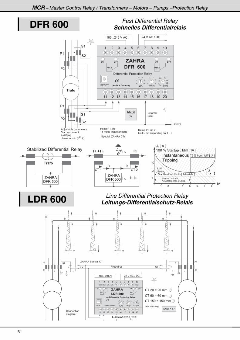
MCR – Master Control Relay / Transformers – Motors – Pumps –Protection Relay
DFR 600 Fast Differential Relay Schnelles Differentialrelais
( � ) . 8 / , ; < ( *
( ( ( � ( ) ( . ( 8 ( / ( , ( ; ( < � *
, $ � � $
� � � � � � � � � � � � � � � � � � � � � 3 � � �
% � B � � 4 � � � 1 . � 4 �3 � 4 � � � � � � E % F%
* 8 *
( * . *
� * ) *
� � � � � � E % F
* 8
( .
� )
*
* = (
� � � L � � � E � � � F�
* = � * = )
* = .
* = 8
( ; 8 + + + � . 8 � $ � % ! � . � $ � % ! � ? � � !
� � � � � �
� � � �
� � � + �
# � # � �
� � � + �
# � # � �
: # �
4 (
� �
� (
4 �
4 (
� �
� (
4 �
� 1 � � 3
� � � � � � �
3 � � � � � ( � 2 � � � �
( 8 � � � � � � � � � � � � � � � � � �
3 � � � � � � � 2 � � � � � �
� � � � � � � - � � � � � � � � � � � � � � � � � � � � � � � � � � �
� � 4 � � � � � � � G % 0 3 % � ! � �
% � > � � � " � � � � � � � � � 2
4 � � � � � � � � � � �
� - � � � � � � E % F �
� � � � � � � � � � � E � � � � � � � � F
% # 4 �
� � ; ,
� 1 � � 3
4 � " � � � 1 � � � � � � � � � � � � � � 3 � � �
� 9 3 � 8 * *
G % 0 3 %
! � � ( ! � � �
"" � D�
" �
� ( � �
� � � �
( �
�
)
. 8 / , ;
( 4 � � � � � � � � � � � � � � � �
% � > � � � " � � � H � � � * = 8 � 4 � � � I
� � � � � � �
4 � � � � � � � �
( * * � J � 4 � � � � � 2 � � � � � � � E � � % � F
4 � " � � � 1 � � � � � - � & � � � � � � E � % � > � � � � � � F
, 8 � J � � � � 2 � � � � � � � E � � % � F
�
� � � � � � �
� % � E � % � F
� %
�
� 9 3 � 8 * *
G % 0 3 %
� � � � � � � � � � �
� � � � � � �
LDR 600 Line Differential Protection Relay Leitungs-Differentialschutz-Relais
( � ) . 8 / , ; < ( *
( ( ( � ( ) ( . ( 8 ( / ( , ( ; ( < � *
� �
� (
4 �
4 (
� �
� (
4 �
4 (
3 � � � 7 � � � � � � �
, $ � � $
( � � � � �
( 4 � � � � � � 1 � 4 6 � � � � 1 3 6 � 2 6 3 4 � � � � � �
7 � � � � � � : � � � �3 � 4 � �� � � � E % F%
* 8 *
( * . *
� * ) *
� � � � � � E % F
* 8
( .
� )
*
* = (
� � � L � � � E � � � F�
* = � * = )
* = .
* = 8
( ; 8 + + + � . 8 � $ � . � $ � % ! � ? � � !
� � � � � � � 3 � � � �
3 � � + (
' # ' 9 9
3 � � + �
' # ' 9 9
! � ! �
G % 0 3 % � 4 � � � � � � ! �
! � � � * � B � � * � � � �
! � � / * � B � / * � � � �
! � � ( 8 * � B � ( 8 * � � � �
� + + + + � � � . $
� � � � � � � � � �
! � � � � � � � � �
� � � �
% # 4 � � B � ; , �
61

MCR – Master Control Relay / Transformers – Motors – Pumps –Control Relay (Product ZAHRA)
Distance 600 Distance 650
Distance Protection Relay Distanzrelais
Die ZAHRA Distanzrelais sind Schutzeinrelais für radiale, ringformige oder beliebig vermaschte Netze die ein- oder mehrseitig gespeist werden. Der gemeinsame Sternpunkt des Netzes kann isoliert, resonanzgeerdet (z.B. über eine Peterson-Spule) , direkt oder niedrigresistiv geerdet sein.
The ZAHRA Distance Relays are for fast, reliable and selective clearance of faults on overhead lines and cables, being fed from one or multiple points. The network can be radial, ring or meshed. The system star point may be isolated, resonance-earthed (e.g. Peterson coil), solidly earthed or low-resistance earthed.
( � ) . 8 / , ; < ( *
( ( ( � ( ) ( . ( 8 ( / ( , ( ; ( < � *
� �
� (
4 �
4 (
3 � �
� � � � � � � �
, $ � � $
� � � � � �
� � 6 � 4 2 � � � 1 3 6 � 2 6 3 4 � � � � � �
7 � � � � � � : � � � �3 � 4 � � � � � � E % F
%
* 8 *
( * . *
� * ) *
� � � � � + � E % F
* 8
( .
� )
*
* = (
� � � L � � � E � � � F�
* = � * = )
* = .
* = 8
( ; 8 + + + � . 8 � $ � . � $ � % ! � ? � � !
� � � � � � � � � � �
3 � � + (
' # ' 9 9
3 � � + �
' # ' 9 9
�++���.$
� � � � (
� � � � �
% # 4 � � B � � ( �
:)
:)
( � ) . 8 / , ;
% %��!
� @ % � @ 6� @ % � @ 6� @ 6
G % G 6
G (
G )
G �
� @ � B � * = ; + + + � � � � #
�
� @
B � 7 � � � � � � � � � � � � � � �
� � � � � � � � � � �
�
�
�
��������� �
�� �
O
�
� 1 �
,$
� � � � � � � � � � �
3��+�(
6 ( 3��+��
3 � � + � )
3 � � + � .
3��+�8
3 � � + � /
3 � � + � ,
3��+�;
3 � � + � <
3 � � + ( *
3��+�((
3 � � + ( �
3 � � + ( )
6 �
6 )
6 ; 6 ( (
6 .
6 8
6 /
6 ,
6 <
6 ( *
6 ( �
6 ( )
3��+�(
6 ( 3��+��
3 � � + � )
3 � � + � .
3��+�8
3 � � + � /
3 � � + � ,
3��+�;
3 � � + � <
3 � � + ( *
3��+�((
3 � � + ( �
3 � � + ( )
6 �
6 )
6 ; 6 ( (
6 .
6 8
6 /
6 ,
6 <
6 ( *
6 ( �
6 ( )
3��+�(.
6 ( .3��+�(.
6 ( 3��+�(8
6 �� ( � (� �
62
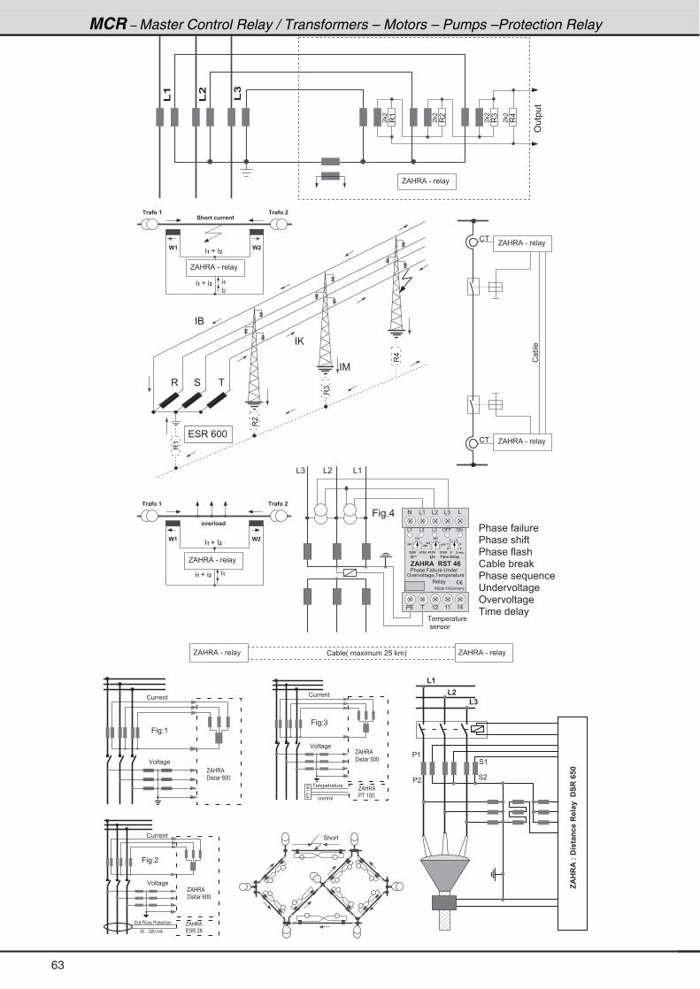
MCR – Master Control Relay / Transformers – Motors – Pumps –Protection Relay
3(
3�
3)
3.
� �
� �
� �
� �
'�����
(�
(�
(�
� � � � � � � �
� � � � � � � � � � �
� � �
� 1 � � 3 � � � 1 � � 3 � �
) �) �
� ; 3 1 6 � 2 8 1 1 � 4 6
� � � � � � � �
� 1 � � 3 � � � 1 � � 3 � �
) �) �
3 9 � 1 � 3 � B
� � � � � � � � � � �
! " � � H � � � � � � � � � 8 � � IG % 0 3 % � - � � � �
! �
! �
! "��
3 4 �
� 6
� @
� 7
3(
3�
3.
3)
� 4 3 � / * *
& � & (& )
9 � � + .
� � � � � � � � � �
� � � � � � � � � �
� � � � � � � � �
! " � � � " �
� � � � � � � � � � � � �
� � � � � � � � �
' � � � � � �
� � � � � � � � �
� � � � � � � �
� � � � � �
G % 0 3 % � - � � � �
G % 0 3 % � - � � � �
G % 0 3 % � - � � � �
G % 0 3 % � - � � � �
G % 0 3 % � - � � � �
G % 0 3 % � - � � � �
� � ( � ( ( ( .
� � �
� � �� � �
� �
� � �� � �
� �
�
� �
�
7 � � � � � : � � � �
' � � � � � � = � � � � � � � �
, $ � � $ � � � � � � �
� � � � � 9 � � � � � � � � �
& ( & � & ) ' 9 9 ' #
' D � . � � � � � � �'
� � � � � � � � � � � � � � � � � � � � � 2 +
# & ( & � & ) &
�
3 � � �
G % 0 3 % � �
� � � � � / * *
� � � 9 � � � � � � � � � � � � � � �
) * + + + + 8 * * � � %
G % 0 3 % � �
� 4 3 � � /
G % 0 3 % � �
� � � ( * *���(** � � � � � � � � �
� � � � � �
9 � � 2 (
$ � � � � �
! � � � �
4 � � �
G % 0 3 % � �
� � � � � / * *
G % 0 3 % � �
� � � � � / * *
9 � � 2 �
9 � � 2 )
! � � � �
! � � � �
$ � � � � �
$ � � � � �
� �
� (
4 �
4 (
( �
( �
( �
��,$��$�7�� �6�42������������� ��
63
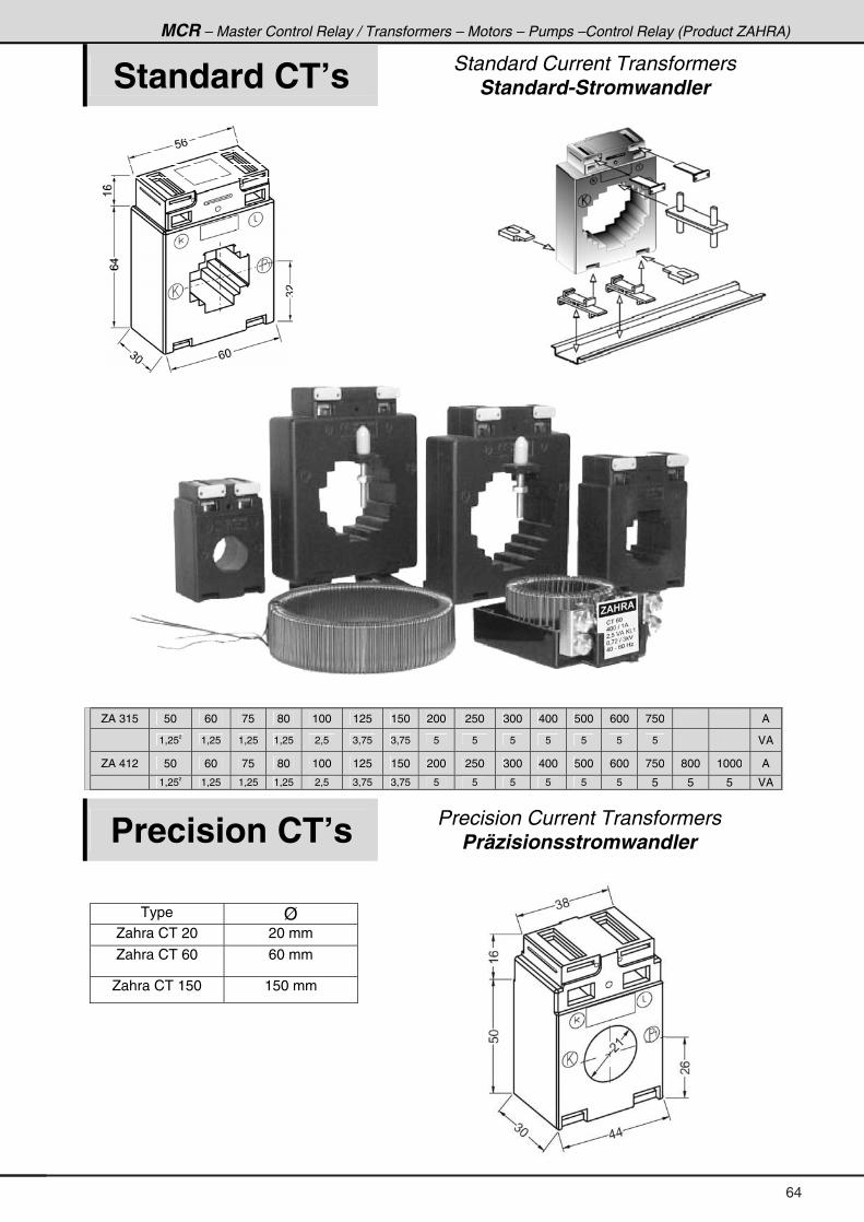
MCR – Master Control Relay / Transformers – Motors – Pumps –Control Relay (Product ZAHRA)
Standard CT’s Standard Current Transformers Standard-Stromwandler
ZA 315 50 60 75 80 100 125 150 200 250 300 400 500 600 750 A
1,252 1,25 1,25 1,25 2,5 3,75 3,75 5 5 5 5 5 5 5 VA
ZA 412 50 60 75 80 100 125 150 200 250 300 400 500 600 750 800 1000 A
1,252 1,25 1,25 1,25 2,5 3,75 3,75 5 5 5 5 5 5 5 5 5 VA
Precision CT’s Precision Current Transformers Präzisionsstromwandler
Type Ø Zahra CT 20 20 mm
Zahra CT 60 60 mm
Zahra CT 150 150 mm
64
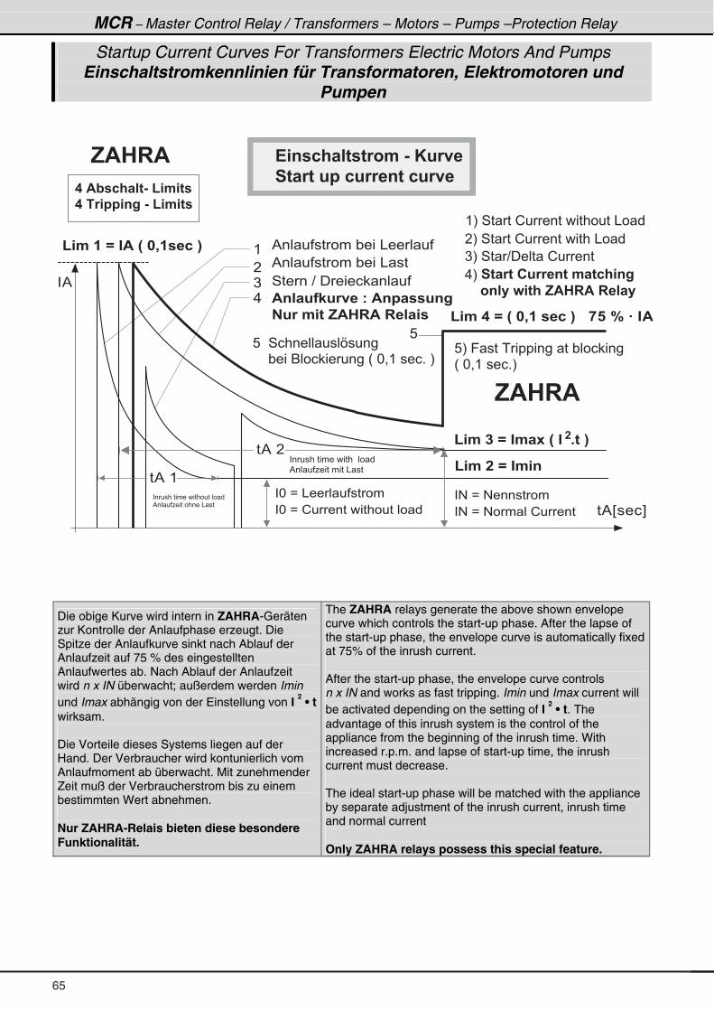
MCR – Master Control Relay / Transformers – Motors – Pumps –Protection Relay
Startup Current Curves For Transformers Electric Motors And Pumps Einschaltstromkennlinien für Transformatoren, Elektromotoren und
Pumpen
( . � � � / � " . 4
� * � B � & � � � � � � � � �
( . � � � / � " . � - � H � " � � + 6 � I
� # � B � # � � � � � � �
� � � 5 � Q � " $
� % E � � � F
� %
(
�
)
.
� * � B � ! � � � � � � � � � � � � � � � � � # � B � # � � � � ! � � � �
8
� % � �
� % � (
% � � � � � � � � � " � � � & � � � � �
% � � � � � � � � � " � � � & � �
4 � � � � ? � � � � � � � � � �
$ 4 � � 8 � < 8 1 9 � � 7 � $ 4 � � � � 8 4 =
� 8 1 � . 6 � , $ � � $ � � � � � �
� ( I � 4 � � � ! � � � � � � � � � � � � � & � �
� I � 4 � � � ! � � � � � � � � � � & � � �
) I � 4 � ? � � � � � ! � � � �
. I � � 6 � 1 6 � � 8 1 1 � 4 6 � . � 6 2 ; 4 =
� � � � 3 4 � � � : 6 ; � , $ � � $ � � � � � �
8 I � 9 � � � � � � � � � � � � � " � � � � � � �
H � * = ( � � � � + I
8 � � 4 � � � � � � � � � V � � � �
� � � � " � � � 6 � � � � � � � � � H � * = ( � � � � + � I
, $ � � $
( . � � � / � H � � 0 � � � � 2 � I
( . � � � / � " $ � H � � 0 � � � 2 � I
� � $ @ � 2 ; � � 6 & � ( . 6 �
� � � 1 � � 4 = � & � ( . 6 �
�
� � � � � � � � � � � � � � � � � � � � � �
% � � � � 1 � � � � � � � � � & � �
� � � � � � � � � � � � � � � � � � � �
% � � � � 1 � � � � � � � � & � �
! 4 � 2 ; � � 6 � 6 1 3 . � & � * 8 1 9 �
� 6 � 1 6 � 8 � � 2 8 1 1 � 4 6 � 2 8 1 9 �
, $ � � $
Die obige Kurve wird intern in ZAHRA-Geräten zur Kontrolle der Anlaufphase erzeugt. Die Spitze der Anlaufkurve sinkt nach Ablauf der Anlaufzeit auf 75 % des eingestellten Anlaufwertes ab. Nach Ablauf der Anlaufzeit wird n x IN überwacht; außerdem werden Imin und Imax abhängig von der Einstellung von I
2 • t
wirksam. Die Vorteile dieses Systems liegen auf der Hand. Der Verbraucher wird kontunierlich vom Anlaufmoment ab überwacht. Mit zunehmender Zeit muß der Verbraucherstrom bis zu einem bestimmten Wert abnehmen. Nur ZAHRA-Relais bieten diese besondere Funktionalität.
The ZAHRA relays generate the above shown envelope curve which controls the start-up phase. After the lapse of the start-up phase, the envelope curve is automatically fixed at 75% of the inrush current. After the start-up phase, the envelope curve controls n x IN and works as fast tripping. Imin und Imax current will be activated depending on the setting of I
2 • t. The
advantage of this inrush system is the control of the appliance from the beginning of the inrush time. With increased r.p.m. and lapse of start-up time, the inrush current must decrease. The ideal start-up phase will be matched with the appliance by separate adjustment of the inrush current, inrush time and normal current Only ZAHRA relays possess this special feature.
65
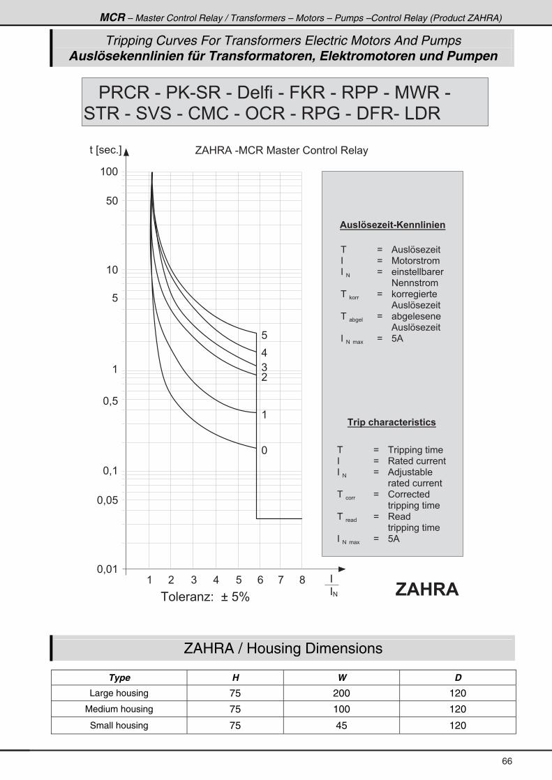
MCR – Master Control Relay / Transformers – Motors – Pumps –Control Relay (Product ZAHRA)
Tripping Curves For Transformers Electric Motors And Pumps Auslösekennlinien für Transformatoren, Elektromotoren und Pumpen
( * *
8 *
( *
8
(
* = 8
* = * (
* = * 8
�
� #
* = (
( � ) . 8 / , ;
� � E � � � + F
(
�
)
.
8
*
� � � � � 1 2 � � U � 8 J �
G % 0 3 % � - 7 ! 3 � 7 � � � � ! � � � � � � 3 � � �
$ 8 � � P � � E � 6 & * � 4 4 � 4 � 4
� � B � % � � � V � � 1 � � �
� � B � 7 � � � � � � �
� �#� B � � � � � � � � � " �
� � # � � � � � � �
� � � � B � � � � � � � �
� � % � � � V � � 1 � � �
� � " � � �
� B � " � � � � � � � �
� � % � � � V � � 1 � � �
� �# � � �
� B � 8 %
� 1 � � 2 ; � 1 � 2 6 � 1 � 6 2 �
� � B � � � � � � � � � � � � �
� � B � 3 � � � � � � � � �
� �#� B � % � > � � � " � �
� � � � � � � � � � �
� �� �
� B � ! � � � � � �
� � � � � � � � � � � � � �
� � � �
� B � 3 � �
� � � � � � � � � � � � � �
� �# � � �
� B � 8 %
� � � � 3 ! 3 � - � � @ - 4 3 � - � � � � � � � - � 9 @ 3 � - � 3 � � � - � 7 C 3 � - �
4 � 3 � - � 4 $ 4 � - � ! 7 ! � - � ' ! 3 � - � 3 � : � - � � 9 3 - � & � 3
� , $ � � $
ZAHRA / Housing Dimensions
Type H W D
Large housing 75 200 120
Medium housing 75 100 120
Small housing 75 45 120
66
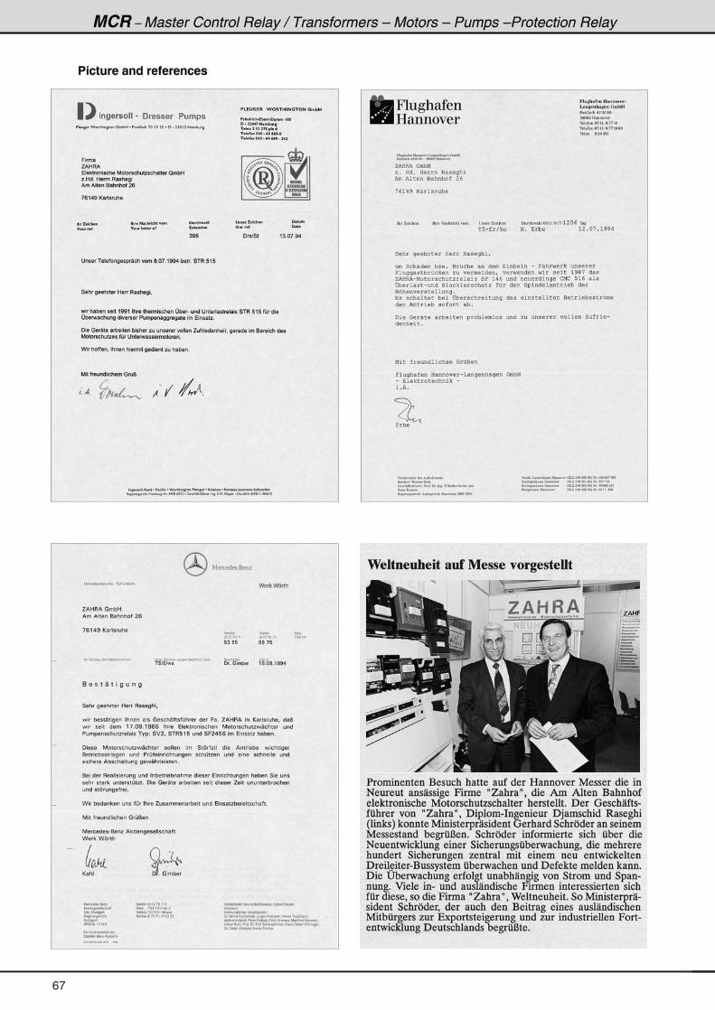
67
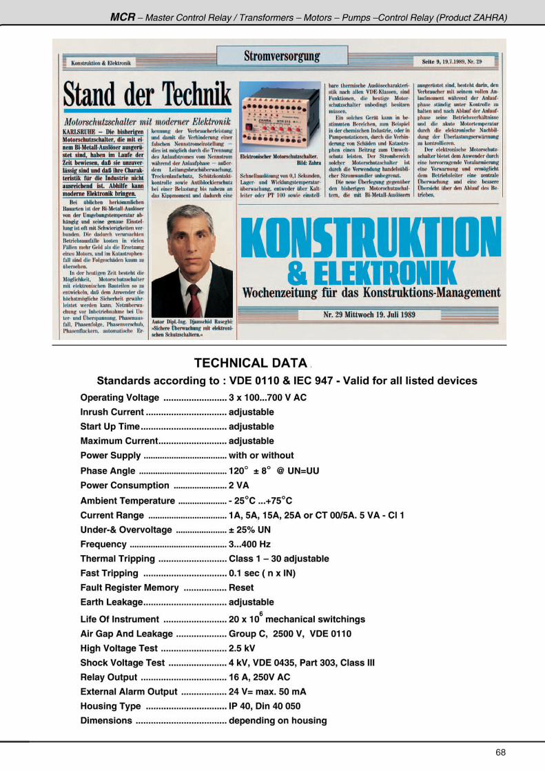
68