Z-Way Developers Documentation - Génération Robots€¦ · Chapter 1 Introduction and Overview...
107
Z-Way Developers Documentation (c) Z-Wave.Me Team, based on Version 2.0
Transcript of Z-Way Developers Documentation - Génération Robots€¦ · Chapter 1 Introduction and Overview...
Z-Way Developers Documentation
(c) Z-Wave.Me Team, based on Version 2.0

2
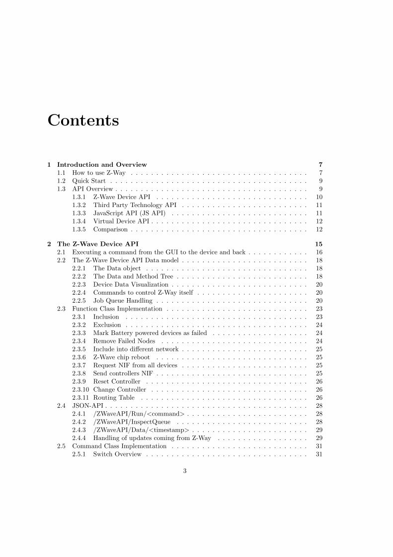
Contents
1 Introduction and Overview 71.1 How to use Z-Way . . . . . . . . . . . . . . . . . . . . . . . . . . . . . . . . . . . 71.2 Quick Start . . . . . . . . . . . . . . . . . . . . . . . . . . . . . . . . . . . . . . . 91.3 API Overview . . . . . . . . . . . . . . . . . . . . . . . . . . . . . . . . . . . . . . 9
1.3.1 Z-Wave Device API . . . . . . . . . . . . . . . . . . . . . . . . . . . . . . 101.3.2 Third Party Technology API . . . . . . . . . . . . . . . . . . . . . . . . . 111.3.3 JavaScript API (JS API) . . . . . . . . . . . . . . . . . . . . . . . . . . . 111.3.4 Virtual Device API . . . . . . . . . . . . . . . . . . . . . . . . . . . . . . . 121.3.5 Comparison . . . . . . . . . . . . . . . . . . . . . . . . . . . . . . . . . . . 12
2 The Z-Wave Device API 152.1 Executing a command from the GUI to the device and back . . . . . . . . . . . . 162.2 The Z-Wave Device API Data model . . . . . . . . . . . . . . . . . . . . . . . . . 18
2.2.1 The Data object . . . . . . . . . . . . . . . . . . . . . . . . . . . . . . . . 182.2.2 The Data and Method Tree . . . . . . . . . . . . . . . . . . . . . . . . . . 182.2.3 Device Data Visualization . . . . . . . . . . . . . . . . . . . . . . . . . . . 202.2.4 Commands to control Z-Way itself . . . . . . . . . . . . . . . . . . . . . . 202.2.5 Job Queue Handling . . . . . . . . . . . . . . . . . . . . . . . . . . . . . . 20
2.3 Function Class Implementation . . . . . . . . . . . . . . . . . . . . . . . . . . . . 232.3.1 Inclusion . . . . . . . . . . . . . . . . . . . . . . . . . . . . . . . . . . . . 232.3.2 Exclusion . . . . . . . . . . . . . . . . . . . . . . . . . . . . . . . . . . . . 242.3.3 Mark Battery powered devices as failed . . . . . . . . . . . . . . . . . . . 242.3.4 Remove Failed Nodes . . . . . . . . . . . . . . . . . . . . . . . . . . . . . 242.3.5 Include into different network . . . . . . . . . . . . . . . . . . . . . . . . . 252.3.6 Z-Wave chip reboot . . . . . . . . . . . . . . . . . . . . . . . . . . . . . . 252.3.7 Request NIF from all devices . . . . . . . . . . . . . . . . . . . . . . . . . 252.3.8 Send controllers NIF . . . . . . . . . . . . . . . . . . . . . . . . . . . . . . 252.3.9 Reset Controller . . . . . . . . . . . . . . . . . . . . . . . . . . . . . . . . 262.3.10 Change Controller . . . . . . . . . . . . . . . . . . . . . . . . . . . . . . . 262.3.11 Routing Table . . . . . . . . . . . . . . . . . . . . . . . . . . . . . . . . . 26
2.4 JSON-API . . . . . . . . . . . . . . . . . . . . . . . . . . . . . . . . . . . . . . . . 282.4.1 /ZWaveAPI/Run/<command> . . . . . . . . . . . . . . . . . . . . . . . . 282.4.2 /ZWaveAPI/InspectQueue . . . . . . . . . . . . . . . . . . . . . . . . . . 282.4.3 /ZWaveAPI/Data/<timestamp> . . . . . . . . . . . . . . . . . . . . . . . 292.4.4 Handling of updates coming from Z-Way . . . . . . . . . . . . . . . . . . 29
2.5 Command Class Implementation . . . . . . . . . . . . . . . . . . . . . . . . . . . 312.5.1 Switch Overview . . . . . . . . . . . . . . . . . . . . . . . . . . . . . . . . 31
3
4 CONTENTS
2.5.2 Sensor Overview . . . . . . . . . . . . . . . . . . . . . . . . . . . . . . . . 32
2.5.3 Meter Overview . . . . . . . . . . . . . . . . . . . . . . . . . . . . . . . . 33
2.5.4 Thermostat Overview . . . . . . . . . . . . . . . . . . . . . . . . . . . . . 33
2.5.5 Door Lock Overview . . . . . . . . . . . . . . . . . . . . . . . . . . . . . . 33
2.5.6 Device Configuration . . . . . . . . . . . . . . . . . . . . . . . . . . . . . . 33
2.5.7 Interview Process . . . . . . . . . . . . . . . . . . . . . . . . . . . . . . . . 33
2.5.8 Device Configuration . . . . . . . . . . . . . . . . . . . . . . . . . . . . . . 34
2.5.9 Associations . . . . . . . . . . . . . . . . . . . . . . . . . . . . . . . . . . . 37
3 JavaScript API 39
3.1 The JavaScript Engine . . . . . . . . . . . . . . . . . . . . . . . . . . . . . . . . . 39
3.2 Accessing the JS API . . . . . . . . . . . . . . . . . . . . . . . . . . . . . . . . . 39
3.3 HTTP Access . . . . . . . . . . . . . . . . . . . . . . . . . . . . . . . . . . . . . . 40
3.4 XML parser . . . . . . . . . . . . . . . . . . . . . . . . . . . . . . . . . . . . . . . 42
3.4.1 var x = new ZXmlDocument() . . . . . . . . . . . . . . . . . . . . . . . . 42
3.4.2 x = new ZXmlDocument(”xml content”) . . . . . . . . . . . . . . . . . . 42
3.4.3 x.root . . . . . . . . . . . . . . . . . . . . . . . . . . . . . . . . . . . . . . 43
3.4.4 x.isXML . . . . . . . . . . . . . . . . . . . . . . . . . . . . . . . . . . . . . 44
3.4.5 x.toString() . . . . . . . . . . . . . . . . . . . . . . . . . . . . . . . . . . . 44
3.4.6 x.findOne(XPathString) . . . . . . . . . . . . . . . . . . . . . . . . . . . . 44
3.4.7 x.findAll(XPathString) . . . . . . . . . . . . . . . . . . . . . . . . . . . . . 44
3.4.8 XML elements . . . . . . . . . . . . . . . . . . . . . . . . . . . . . . . . . 44
3.5 Other JavaScript Extensions . . . . . . . . . . . . . . . . . . . . . . . . . . . . . . 44
3.5.1 Debugging JavaScript code . . . . . . . . . . . . . . . . . . . . . . . . . . 47
4 The Automation Subsystem 49
4.1 How to get to the automation engine . . . . . . . . . . . . . . . . . . . . . . . . . 49
4.2 The Event Bus . . . . . . . . . . . . . . . . . . . . . . . . . . . . . . . . . . . . . 49
4.2.1 Emitting events . . . . . . . . . . . . . . . . . . . . . . . . . . . . . . . . . 50
4.2.2 Catching (binding to) events . . . . . . . . . . . . . . . . . . . . . . . . . 50
4.3 Module-Syntax . . . . . . . . . . . . . . . . . . . . . . . . . . . . . . . . . . . . . 51
4.3.1 Module.json . . . . . . . . . . . . . . . . . . . . . . . . . . . . . . . . . . . 51
4.3.2 index.js . . . . . . . . . . . . . . . . . . . . . . . . . . . . . . . . . . . . . 51
4.4 Available Core Modules . . . . . . . . . . . . . . . . . . . . . . . . . . . . . . . . 52
4.4.1 Cron, the timer module . . . . . . . . . . . . . . . . . . . . . . . . . . . . 52
4.4.2 The Virtual Device Module . . . . . . . . . . . . . . . . . . . . . . . . . . 53
4.4.3 DeviceCollection module . . . . . . . . . . . . . . . . . . . . . . . . . . . . 53
5 Virtual Device API (vDev) 55
5.1 The virtual device . . . . . . . . . . . . . . . . . . . . . . . . . . . . . . . . . . . 55
5.1.1 Types and Ids . . . . . . . . . . . . . . . . . . . . . . . . . . . . . . . . . 55
5.1.2 Virtual Device Ids . . . . . . . . . . . . . . . . . . . . . . . . . . . . . . . 56
5.1.3 Virtual Device Type . . . . . . . . . . . . . . . . . . . . . . . . . . . . . . 56
5.1.4 Access to Virtual Devices . . . . . . . . . . . . . . . . . . . . . . . . . . . 56
5.1.5 Virtual Device Usage / Commands . . . . . . . . . . . . . . . . . . . . . . 56
5.1.6 Virtual Device Usage / Values . . . . . . . . . . . . . . . . . . . . . . . . 57
5.1.7 How to create your own virtual devices . . . . . . . . . . . . . . . . . . . 57
5.2 Notifications and events . . . . . . . . . . . . . . . . . . . . . . . . . . . . . . . . 58
CONTENTS 5
6 Z-Way Data Model Reference 596.1 zway . . . . . . . . . . . . . . . . . . . . . . . . . . . . . . . . . . . . . . . . . . . 596.2 controller . . . . . . . . . . . . . . . . . . . . . . . . . . . . . . . . . . . . . . . . 596.3 Devices . . . . . . . . . . . . . . . . . . . . . . . . . . . . . . . . . . . . . . . . . 616.4 Device . . . . . . . . . . . . . . . . . . . . . . . . . . . . . . . . . . . . . . . . . . 616.5 Instances . . . . . . . . . . . . . . . . . . . . . . . . . . . . . . . . . . . . . . . . 62
6.5.1 CommandClass . . . . . . . . . . . . . . . . . . . . . . . . . . . . . . . . . 636.6 Data . . . . . . . . . . . . . . . . . . . . . . . . . . . . . . . . . . . . . . . . . . . 63
7 Command Class Reference 657.1 FirmwareUpdate (0x7A/122) . . . . . . . . . . . . . . . . . . . . . . . . . . . . . 657.2 Alarm (0x71/113) . . . . . . . . . . . . . . . . . . . . . . . . . . . . . . . . . . . 667.3 Command Class Alarm Sensor (0x9c/156) . . . . . . . . . . . . . . . . . . . . . . 667.4 Command Class Association (0x85/133) . . . . . . . . . . . . . . . . . . . . . . . 677.5 Command Class Basic (0x20/32) . . . . . . . . . . . . . . . . . . . . . . . . . . . 687.6 Command Class Battery (0x80/128) . . . . . . . . . . . . . . . . . . . . . . . . . 697.7 CentralScene (0x5B/91) . . . . . . . . . . . . . . . . . . . . . . . . . . . . . . . . 697.8 ClimateControlSchedule (0x46/70) . . . . . . . . . . . . . . . . . . . . . . . . . . 697.9 Command Class Clock (0x81/129) . . . . . . . . . . . . . . . . . . . . . . . . . . 697.10 Command Class Configuration(0x70/112) . . . . . . . . . . . . . . . . . . . . . . 707.11 Command Class DoorLock (0x62/98) . . . . . . . . . . . . . . . . . . . . . . . . . 717.12 Command Class Door Lock Logging (0x4C/76) . . . . . . . . . . . . . . . . . . . 737.13 Command Class Indicator (0x87/135) . . . . . . . . . . . . . . . . . . . . . . . . 737.14 Command Class Meter (0x32/50) . . . . . . . . . . . . . . . . . . . . . . . . . . . 747.15 MeterTableMonitor (0x3D/61) . . . . . . . . . . . . . . . . . . . . . . . . . . . . 757.16 Command Class Multichannel Association (0x8e/142) . . . . . . . . . . . . . . . 767.17 Command Class NodeNaming (0x77/119) . . . . . . . . . . . . . . . . . . . . . . 777.18 PowerLevel (0x73/115) . . . . . . . . . . . . . . . . . . . . . . . . . . . . . . . . . 797.19 Command Class Protection (0x75/117) . . . . . . . . . . . . . . . . . . . . . . . . 807.20 Command Class SceneActivation(0x2B/43) . . . . . . . . . . . . . . . . . . . . . 827.21 Command Class SceneControllerConf (0x2d/45) . . . . . . . . . . . . . . . . . . 827.22 Command Class SceneActuatorConf (0x2C/44) . . . . . . . . . . . . . . . . . . . 837.23 Schedule (0x53/83) . . . . . . . . . . . . . . . . . . . . . . . . . . . . . . . . . . . 837.24 Command Class ScheduleEntryLock (0x4e/78) . . . . . . . . . . . . . . . . . . . 847.25 Command Class SensorBinary (0x30/48) . . . . . . . . . . . . . . . . . . . . . . . 867.26 Command Class Sensor Configuration (0x9e/158) . . . . . . . . . . . . . . . . . . 867.27 Command Class Sensor Multilevel (0x31/49) . . . . . . . . . . . . . . . . . . . . 877.28 Command Class Switch All (0x27/39) . . . . . . . . . . . . . . . . . . . . . . . . 877.29 Command Class SwitchColor (0x33/51) . . . . . . . . . . . . . . . . . . . . . . . 887.30 Command Class SwitchBinary(0x25/37) . . . . . . . . . . . . . . . . . . . . . . . 907.31 Command Class SwitchMultilevel (0x26/38) . . . . . . . . . . . . . . . . . . . . . 917.32 Command Class ThermostatFanMode(0x44/68) . . . . . . . . . . . . . . . . . . . 927.33 Command Class ThermostatFanState(0x45/69) . . . . . . . . . . . . . . . . . . . 937.34 Command Class ThermostatMode (0x40/64) . . . . . . . . . . . . . . . . . . . . 937.35 Command Class ThermostatOperatingState (0x42/66) . . . . . . . . . . . . . . . 947.36 Command Class ThermostatSetPoint (0x43/67) . . . . . . . . . . . . . . . . . . . 947.37 Command Class UserCode (0x63/99) . . . . . . . . . . . . . . . . . . . . . . . . . 967.38 Command Class Time (0x8a/138) . . . . . . . . . . . . . . . . . . . . . . . . . . 967.39 Command Class TimeParameters (0x8b/139) . . . . . . . . . . . . . . . . . . . . 97

6 CONTENTS
7.40 Command Class Wakeup (0x84/132) . . . . . . . . . . . . . . . . . . . . . . . . . 987.41 Other command classes not exposed on the API . . . . . . . . . . . . . . . . . . 99
8 Function Class Reference 101TODOs: check cap 2,2.1,2.2, describe Restore Function
Chapter 1
Introduction and Overview
1.1 How to use Z-Way
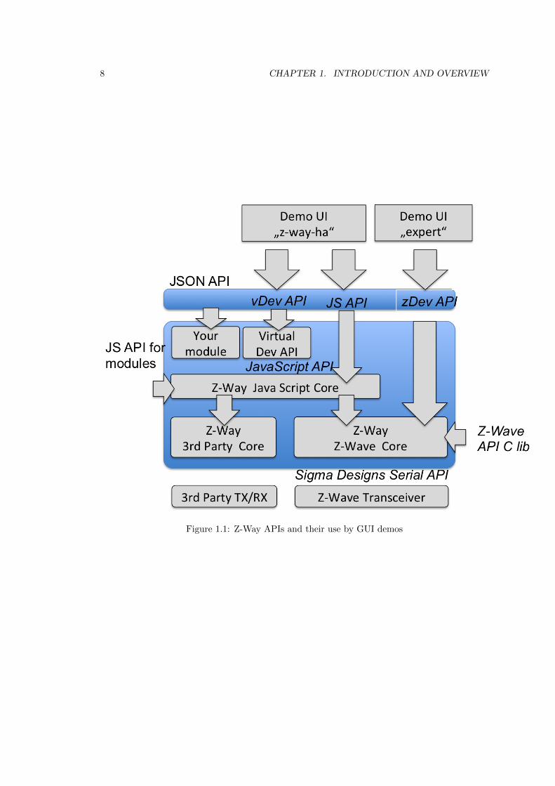
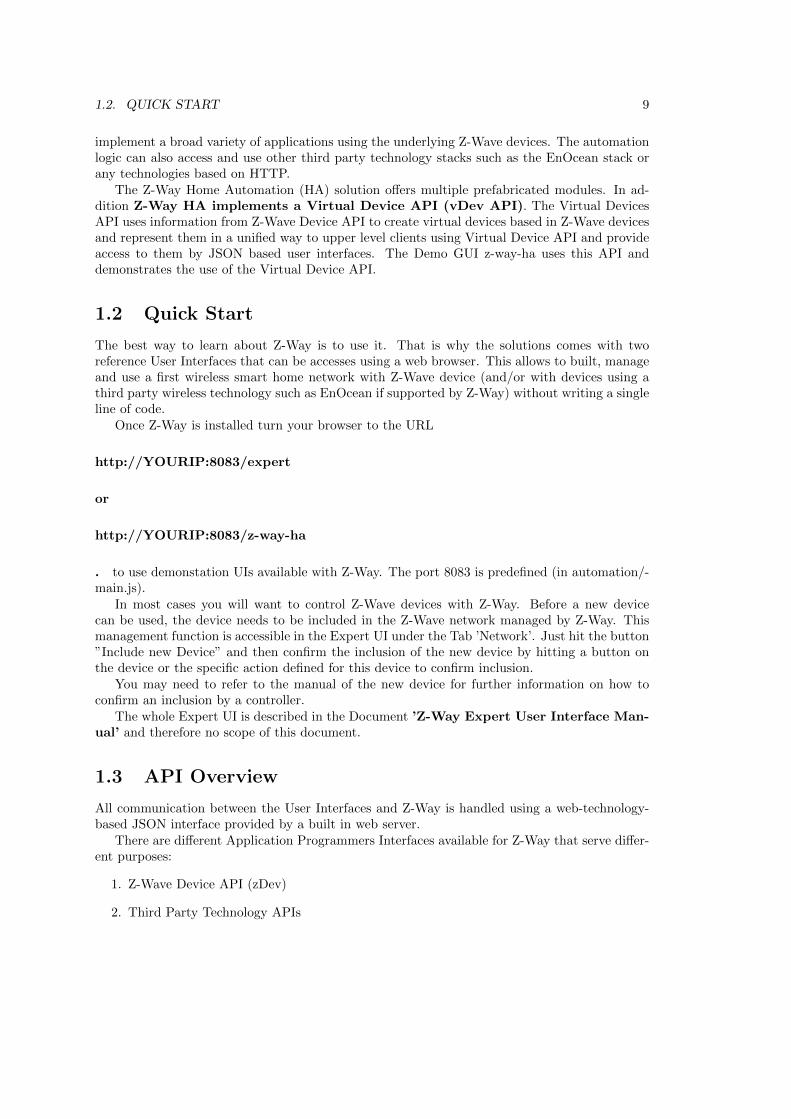
Z-Way offers multiple Application Programmers Interfaces (API) that are partly built on eachother. Figure 1.1 shows the general structure of Z-Way with focus on the APIs. The mostimportant part of Z-Way is the Z-Wave core. The Z-Wave core uses the standard Sigma DesignsSerial API to communicate with a Z-Wave compatible transceiver hardware but enhanced withsome Z-Way specific functions such as Frequency Change. The standard interface is not publicbut available for owners of the Sigma Designs Development Kit (SDK) 1 only.
The Z-Wave core services can be accessed directly using the Z-Wave Device API (zDev API).There are two Z-Wave Device API versions available:
• JSON API: All functions are available using a JSON API implemented by an embeddedwebserver. The ”Expert” UI is using this interface and serves both as programmers andinstallers User Interface to operate the network and as reference implementation to demon-strate the use of this API. The Expert UI is completely written in AJAX Technology.
• C Library API: All functions of the JSON API are available as C library function too. Inthe folder /z-way-devel there are all header files with the function prototypes. All functioncalls and the whole data model are identical. The URL
http://razberry.zwave.me/fileadmin/z-way-test.zip provides a sample applicationwritten in standard C that makes use of the C level API to demonstrate its application.Makefiles and project files for compilation on Linux and OSX are provided together withthe sample code.
The Z-Wave device API only allows the management of the Z-Wave network andthe control and management of the devices as such. No higher order logic except the so calledassociations between two Z-Wave devices can be used here.
For all automation and higher order logic a Javascript automation engine is avail-able. This engine is also shipped with Z-Way. There is also a possibility to create your ownhome automation engine working in addition or instead of the original Z-Way Home Automationengine. The implementation of the Java Script engine is organized in so called modules that
1The Sigma Designs SDK is available from Digikey (www.digikey.com). Depending on the hardware optionschosen the price varies between 2000 and 4000 USD
7
8 CHAPTER 1. INTRODUCTION AND OVERVIEW
Figure 1.1: Z-Way APIs and their use by GUI demos
1.2. QUICK START 9
implement a broad variety of applications using the underlying Z-Wave devices. The automationlogic can also access and use other third party technology stacks such as the EnOcean stack orany technologies based on HTTP.
The Z-Way Home Automation (HA) solution offers multiple prefabricated modules. In ad-dition Z-Way HA implements a Virtual Device API (vDev API). The Virtual DevicesAPI uses information from Z-Wave Device API to create virtual devices based in Z-Wave devicesand represent them in a unified way to upper level clients using Virtual Device API and provideaccess to them by JSON based user interfaces. The Demo GUI z-way-ha uses this API anddemonstrates the use of the Virtual Device API.
1.2 Quick Start
The best way to learn about Z-Way is to use it. That is why the solutions comes with tworeference User Interfaces that can be accesses using a web browser. This allows to built, manageand use a first wireless smart home network with Z-Wave device (and/or with devices using athird party wireless technology such as EnOcean if supported by Z-Way) without writing a singleline of code.
Once Z-Way is installed turn your browser to the URL
http://YOURIP:8083/expert
or
http://YOURIP:8083/z-way-ha
. to use demonstation UIs available with Z-Way. The port 8083 is predefined (in automation/-main.js).
In most cases you will want to control Z-Wave devices with Z-Way. Before a new devicecan be used, the device needs to be included in the Z-Wave network managed by Z-Way. Thismanagement function is accessible in the Expert UI under the Tab ’Network’. Just hit the button”Include new Device” and then confirm the inclusion of the new device by hitting a button onthe device or the specific action defined for this device to confirm inclusion.
You may need to refer to the manual of the new device for further information on how toconfirm an inclusion by a controller.
The whole Expert UI is described in the Document ’Z-Way Expert User Interface Man-ual’ and therefore no scope of this document.
1.3 API Overview
All communication between the User Interfaces and Z-Way is handled using a web-technology-based JSON interface provided by a built in web server.
There are different Application Programmers Interfaces available for Z-Way that serve differ-ent purposes:
1. Z-Wave Device API (zDev)
2. Third Party Technology APIs
10 CHAPTER 1. INTRODUCTION AND OVERVIEW
3. JavaScript API
4. Virtual Device API/Business Logic API (vDev)
1.3.1 Z-Wave Device API
The Z-Wave Device API implements the direct access to the Z-Wave network as such. All Z-Wave devices are referred to by their unique identification in the wireless network - the NodeId. Z-Wave devices may have different instances of the same function, also called channels (forexample sockets in a power strip). The Z-Wave Device API refers to them as daughter objectsof the physical device object identified by an instance Id. In case there only one instance theinstance Id = 0 is used.
All device variables and available commands in a Z-Wave device are grouped in so calledcommand classes. The Z-Wave API allows direct access to all parameters, values and commandsof these command class structures.
Beside the devices the Z-Wave Device API also offers access to the management interface ofthe network. These functions are implemented as so called function classes within the object’controller’ or on the top level ’z-way’ object.
The Z-Wave Device API can be accessed on the JSON API using the url path
http://YOURIP:8083/ZWaveAPI/*
Device objects or commands of these objects are accessed by
http://YOURIP:8083/ZWaveAPI/Run/devices[*].*
http://YOURIP:8083/ZWaveAPI/Run/devices[x].instances[y].*
http://YOURIP:8083/ZWaveAPI/Run/devices[x].instances[y].commandClasses[z].*
the whole data tree of the Z-Wave network is accessed using
http://YOURIP:8083/ZWaveAPI/Data/*
Attention: The Installer UI is a complete reference of the Z-Wave API. It showshow to use all function it reveals the dynamics of the stack backend and visualizesall internal variables accessible on the API. The chapter 2 describes the Z-Wave DeviceAPI in detail.
The section ’Function Classes’ in chapter 2.3 explains the different management functions andhow they can be used and will use the Expert UI dialogs as application example. The section’Function Class Reference’ in chapter 8 all function classes available.
The control of devices is implemented in Command Classes. The section ’Command ClassImplementation’ is again using certain dialogs of the Expert UI to explain how to access thesefunctions. The chapter 7 documents all command class functions.
In order to access device and network related data in Z-Way, knowledge of the Z-Way datamodel is essential. The chapter 6 gives the necessary insight into the data model. All data ofZ-Way are exposed on the Expert UI.
1.3. API OVERVIEW 11
1.3.2 Third Party Technology API
Third party Technology APIs implement the same logic as the Z-Wave device API for otherwireless technologies such as EnOcean.
For more information please refer to the technology specific descriptions.
1.3.3 JavaScript API (JS API)
The Z-Wave Device API or any other Third Party technology API do not offer any higher orderlogic support but the pure access to functions and parameters only.
Z-Way offers an automation engine to overcome this restriction. A server-side JavaScript Runtime environment allows writing JavaScript modules that are executed within Z-Way (means onthe server). The same time all functions of the JS API can also be access on the client side (theweb browser). This offers some cool debug and test capabilities. Among others it is possible towrite whole JS functions right into the URL or the browser.
The JS API can be accessed from the web browser with the URL
http://YOURIP:8083/JS/Run/*
Among others the whole Z-Wave Device API is available within the JS API usingthe object ’zway’. As a result the following three statements refer to the very same function:
1. http://YOURIP:8083/ZWaveAPI/Run/devices[3].* Client Side URL access usingthe Z-Wave Device API.
2. http://YOURIP:8083/JS/Run/zway.devices[3].*: Client Side URL access using theJS API
3. zway.devices[3].*: Server Side access using the JS and the public zway object
Due to the scripting nature of JavaScript it is possible to ’inject’ code at run time using theinterface. Here a nice example how to use the Java Script setInterval function:
Listing 1.1: Polling of device #2
1 /JS/Run/ s e t I n t e r v a l ( func t i on ( ) {2 zway . de v i c e s [ 2 ] . Bas ic . Get ( ) ;3 } , 300∗1000) ;
This code will, once ’executed’ as URL within a web browser, call the Get() command of thecommand class Basic of Node Id 2 every 300 seconds.
A very powerful function of the JS API is the ability to bind functions to certain values ofthe device tree. They get then executed when the value changes. Here is an example for thisbinding. The device No. 3 has a command class SensorMultilevel that offers the variable level.The following call - both available on the client side and on the server side - will bind a simplealert function to the change of the variable.
Listing 1.2: Bind a function
4 zway . d ev i c e s [ 3 ] . S e n s o r M u l t i l e v e l . data [ 1 ] . l e v e l . bind ( func t i on ( ) {5 debugPrint ( ’CHANGED TO: ’ + t h i s . va lue + ’ \n ’ ) ;6 } ) ;
12 CHAPTER 1. INTRODUCTION AND OVERVIEW
2
Chapter 3 and 6 describe the whole JS API in detail. The names and Ids of the differentcommand classes as well as their instance variables can be found in the Annex.
JavaScript modules can and will generate new functions that are accessible using the JSONinterface. For simplification function calls on the API (means on the client side) are written inURL style starting with the word ’ZAutomation’:
/ZAutomation/JSfunction/JParameter == JSfunction(JParameter)
1.3.4 Virtual Device API
One of the (server side) JavaScript modules already available is a mapping of all physical devicesand functions into virtual devices. The purpose of this mapping is to simplify and to unify theimplementation of a Graphical User Interface.
All functions and all instances of a physical device - that are represented as daughter objectsin the Z-Wave Device API - are enrolled into individual virtual devices.
In case the Z-Wave API shows one single physical device with two channels, while the VirtualDevice API will show two devices with similar functionality. In case the Z-Wave API shows aphysical device with several different functions (like a binary switch and a analog sensor in onedevice) the Virtual Device API (vDev API) will show them as several devices with one functioneach.
The vDev is accessed using the HTTP REST API in a slightly different style than zDev API.All devices, variables and commands are encoded into a URL style for easier handling in AJAXcode. A typical client side command in the vDev API looks like
http://YOURIP:8083/ZAutomation/api/v1/devices/ZWayVDev 6:0:37/command/off
’api’ points to the vDev API function, ’v1’ is just a constant to allow future extensions. Thedevices are referred by a name that is automatically generated from the Z-Wave Device API.The vDev also unifies the commands ’command’ and the parameters, here ’off’.
On the server side the very same command would be encoded in a JavaScript style.
dev = this.controller.devices.get(’ZWayVDev 6:0:37’); dev.command(’off’);
The vDev API also offers support for notifications, locations information, the use of othermodules etc. For details please refer to Chapter ??.
1.3.5 Comparison
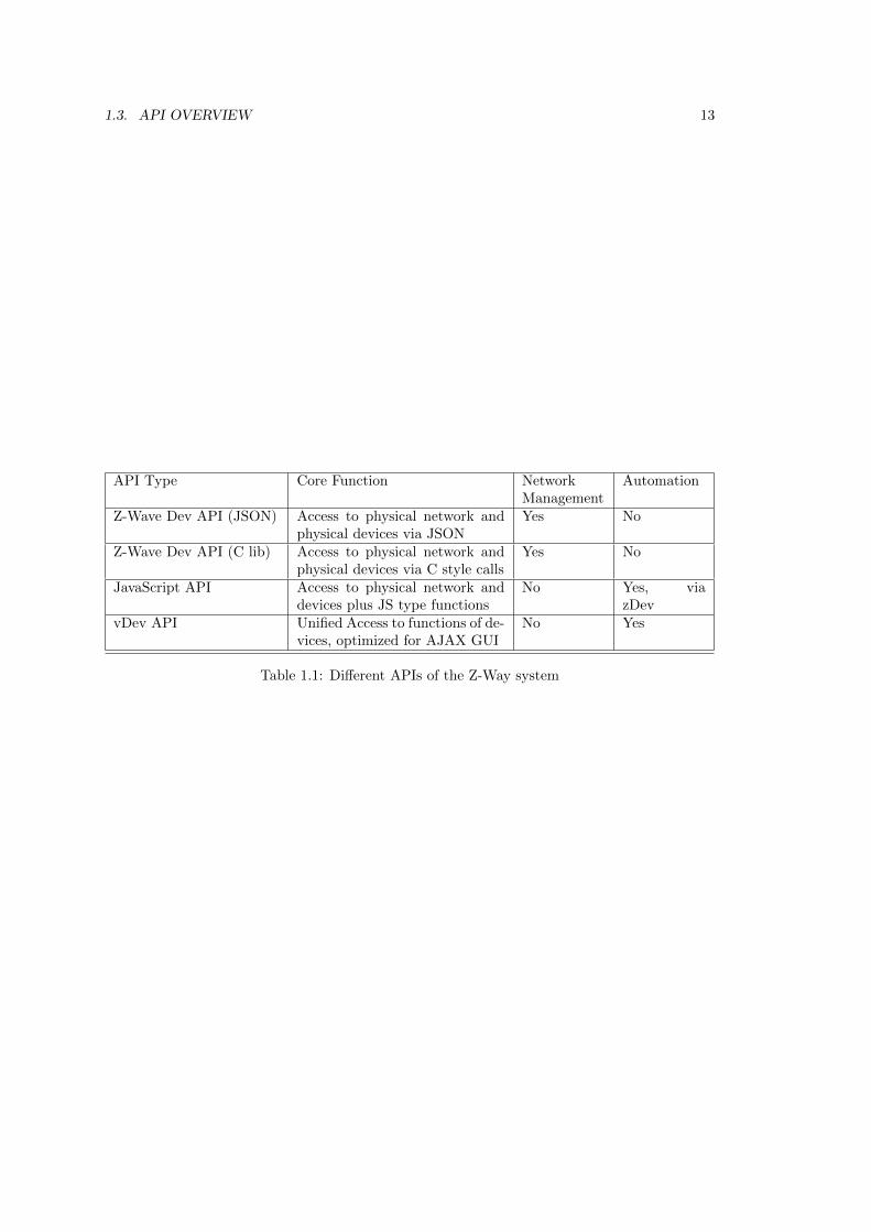
Table 1.1 summarizes the functions of the different APIs.For demo and sample code please refer to the following sources:
1. Z-Wave Device API JSON Expert UI on http://YOURIP:8083/expert
2. Z-Wave C Library API Header files in folder /z-way-devel
3. JavaScript API Modules in folder /automation
4. vDev API z-way-ha UI on http://YOURIP:8083/z-way-ha
2Please note that the Sensor Multilevel Command class data is an array index by the scale Id. Other commandclasses such as Basic do not have this index but allow direct access using CommandClassName.data.level
1.3. API OVERVIEW 13
API Type Core Function NetworkManagement
Automation
Z-Wave Dev API (JSON) Access to physical network andphysical devices via JSON
Yes No
Z-Wave Dev API (C lib) Access to physical network andphysical devices via C style calls
Yes No
JavaScript API Access to physical network anddevices plus JS type functions
No Yes, viazDev
vDev API Unified Access to functions of de-vices, optimized for AJAX GUI
No Yes
Table 1.1: Different APIs of the Z-Way system

14 CHAPTER 1. INTRODUCTION AND OVERVIEW
Chapter 2
The Z-Wave Device API
This chapter describes the Z-Wave Device API and its use in detail. All examples will use theHTTP/JSON API notation. Please note that the C library notation offers equal functionality.
The Z-Wave Device API is the north bound interface of the Z-Wave Core. This Z-Wave coreimplement the whole control logic of the the Z-Wave network. The two main functions are
• Management of the network. This includes including and excluding devices, managing therouting and rerouting of the network an executing some housekeeping functions to keepthe network clean and stable. In the Z-Wave terminology all these functions are called’function classes’ and they are described in section 2.3. The function classes can be seenas functions offered by the controller itself. Hence the variables and status parameters ofthe networks are offered by an object called ’controller’.
• Execution of commands offered by the wireless devices as such switching switches anddimming dimmers. Z-Wave groups the command and their corresponding variables intoso called command classes. The Z-Wave API offers access to these command classes withtheir variables and their commands according to the abilities od the respective device.
The next chapters first explain the timings of the communication in a wireless Z-Wave network.Then the data model is presented that reflects the real data and status information in thenetwork.
The description of function Classes and command Classes and their access using the JSONAPI complete the description of the Z-Wave Device API. For a full reference of function classesand command classes please refer to the Annex.
15
16 CHAPTER 2. THE Z-WAVE DEVICE API
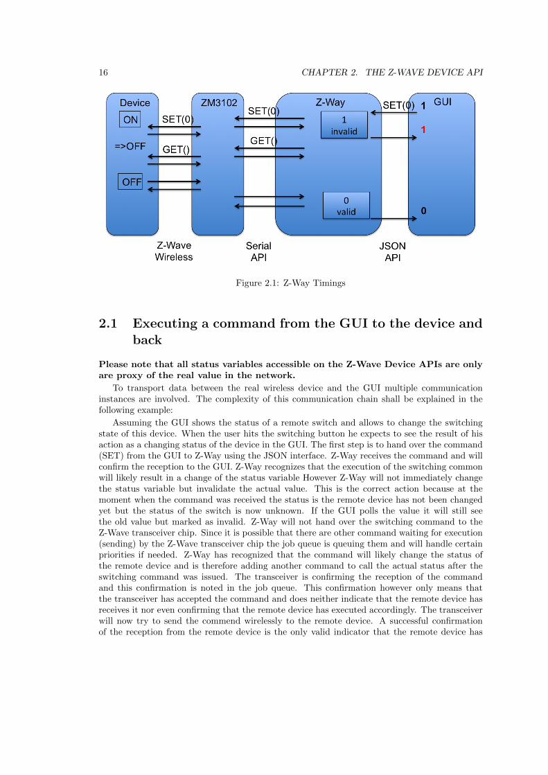
Figure 2.1: Z-Way Timings
2.1 Executing a command from the GUI to the device andback
Please note that all status variables accessible on the Z-Wave Device APIs are onlyare proxy of the real value in the network.
To transport data between the real wireless device and the GUI multiple communicationinstances are involved. The complexity of this communication chain shall be explained in thefollowing example:
Assuming the GUI shows the status of a remote switch and allows to change the switchingstate of this device. When the user hits the switching button he expects to see the result of hisaction as a changing status of the device in the GUI. The first step is to hand over the command(SET) from the GUI to Z-Way using the JSON interface. Z-Way receives the command and willconfirm the reception to the GUI. Z-Way recognizes that the execution of the switching commonwill likely result in a change of the status variable However Z-Way will not immediately changethe status variable but invalidate the actual value. This is the correct action because at themoment when the command was received the status is the remote device has not been changedyet but the status of the switch is now unknown. If the GUI polls the value it will still seethe old value but marked as invalid. Z-Way will not hand over the switching command to theZ-Wave transceiver chip. Since it is possible that there are other command waiting for execution(sending) by the Z-Wave transceiver chip the job queue is queuing them and will handle certainpriorities if needed. Z-Way has recognized that the command will likely change the status ofthe remote device and is therefore adding another command to call the actual status after theswitching command was issued. The transceiver is confirming the reception of the commandand this confirmation is noted in the job queue. This confirmation however only means thatthe transceiver has accepted the command and does neither indicate that the remote device hasreceives it nor even confirming that the remote device has executed accordingly. The transceiverwill now try to send the commend wirelessly to the remote device. A successful confirmationof the reception from the remote device is the only valid indicator that the remote device has

2.1. EXECUTING A COMMAND FROM THE GUI TO THE DEVICE AND BACK 17
received the command (again, not that it was executed!). The second command (GET) is nowtransmitted the very same way and confirmed by the remote device. This device will now sent aREPORT command back to Z-Way reporting the new status of the switching device. Now thetransceiver of Z-Way has to confirm the reception. The transceiver will then send the new valueto the Z-Way engine by issuing a commas via the serial interface. Z-Way receives the report andwill update the switching state and validate the value. From now on the GUI will receive a newstate when polling.
18 CHAPTER 2. THE Z-WAVE DEVICE API
2.2 The Z-Wave Device API Data model
Z-Way holds all data of the Z-Way network in a data holder structure. The data holder structureis a hierarchical tree of data elements.
Following the object-oriented software paradigm the different commands targeting the net-work or individual devices are also embedded into the data objects as object methods.
Each data element is handled in a data object that contains the data element and somecontextual data.
2.2.1 The Data object
Each Data element such as devices[nodeID].data.nodeId is an object with the following childelements:
• value: the value itself
• name: the name of the data object
• updateTime: timestamp of the last update of this particular value
• invalidateTime: timestamp when the value was invalidated by issuing a Get command toa device and expecting a Report command from the device
Every time a command is issued that will have impact on a certain data holder value thetime of the request is stored in ”invalidateTime” and the ”updated” flag is set to ”False”. Thisallows to track when a new data value was requested from the network when this new data valuewas provided by the network.
This is particularly true if Z-Way is sending a SET command. In this case the data valueis invalidated with the ”SET” commands and gets validated back when the result of the GETcommand was finally stored in the data model.
To maintain compatibility with Javascript the data object has the following methods imple-mented
• valueOf(): this allows to obmit .value in JS code, hence write as an example data.level =255
• updated(): alias to updateTime
• invalidated(): alias to invalidateTime
These aliases are not enumerated if the dataholder is requested (data.level returns value: 255,name: ”level”, updatedTime: 12345678, invalidatedTime: 12345678).
2.2.2 The Data and Method Tree
The root of the data tree has two important child objects:
• controller, this is the data object that holds all data and methods (commands, mainlyfunction classes) related to the Z-Way controller as such
• devices array, this is the object array that holds the device specific data and methods(commands, mainly command classes).
Chapter 6 gives a complete overview of the data and method tree.
2.2. THE Z-WAVE DEVICE API DATA MODEL 19
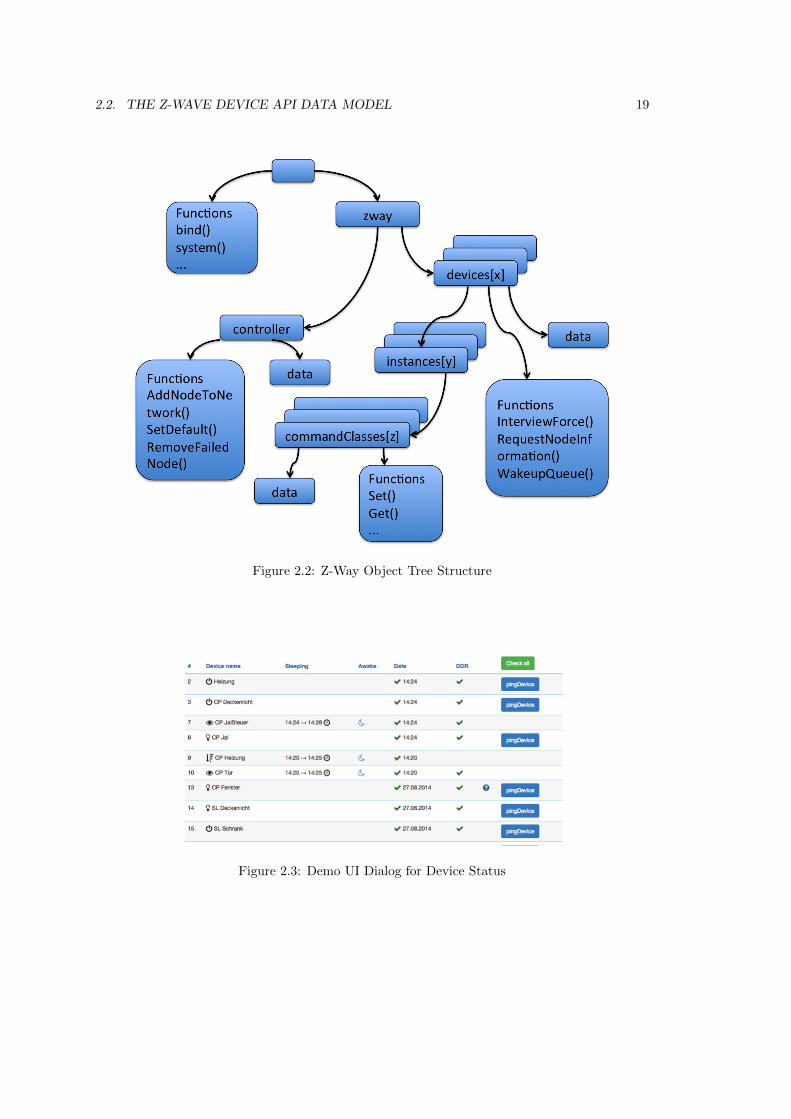
Figure 2.2: Z-Way Object Tree Structure
Figure 2.3: Demo UI Dialog for Device Status
20 CHAPTER 2. THE Z-WAVE DEVICE API
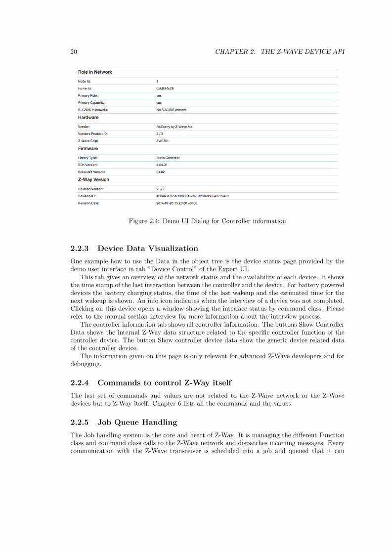
Figure 2.4: Demo UI Dialog for Controller information
2.2.3 Device Data Visualization
One example how to use the Data in the object tree is the device status page provided by thedemo user interface in tab ”Device Control” of the Expert UI.
This tab gives an overview of the network status and the availability of each device. It showsthe time stamp of the last interaction between the controller and the device. For battery powereddevices the battery charging status, the time of the last wakeup and the estimated time for thenext wakeup is shown. An info icon indicates when the interview of a device was not completed.Clicking on this device opens a window showing the interface status by command class. Pleaserefer to the manual section Interview for more information about the interview process.
The controller information tab shows all controller information. The buttons Show ControllerData shows the internal Z-Way data structure related to the specific controller function of thecontroller device. The button Show controller device data show the generic device related dataof the controller device.
The information given on this page is only relevant for advanced Z-Wave developers and fordebugging.
2.2.4 Commands to control Z-Way itself
The last set of commands and values are not related to the Z-Wave network or the Z-Wavedevices but to Z-Way itself. Chapter 6 lists all the commands and the values.
2.2.5 Job Queue Handling
The Job handling system is the core and heart of Z-Way. It is managing the different Functionclass and command class calls to the Z-Wave network and dispatches incoming messages. Everycommunication with the Z-Wave transceiver is scheduled into a job and queued that it can
2.2. THE Z-WAVE DEVICE API DATA MODEL 21
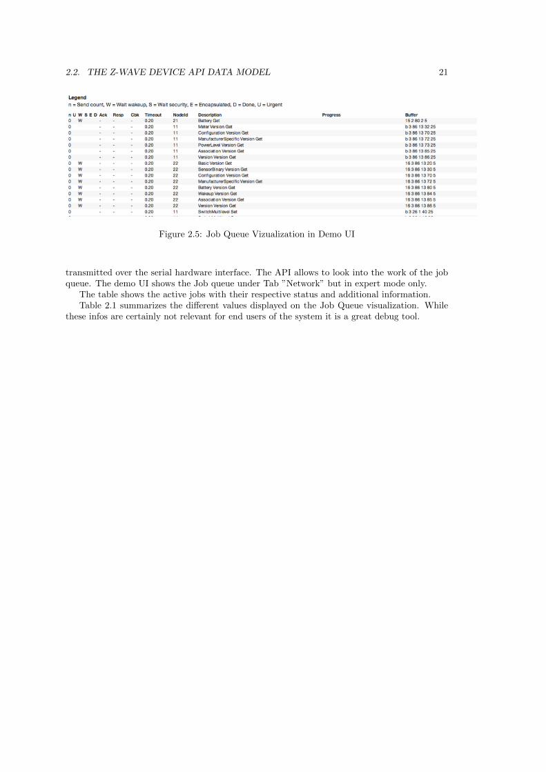
Figure 2.5: Job Queue Vizualization in Demo UI
transmitted over the serial hardware interface. The API allows to look into the work of the jobqueue. The demo UI shows the Job queue under Tab ”Network” but in expert mode only.
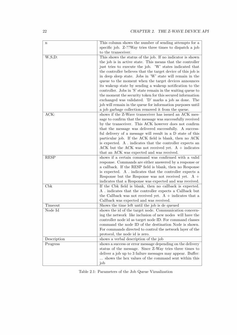
The table shows the active jobs with their respective status and additional information.Table 2.1 summarizes the different values displayed on the Job Queue visualization. While
these infos are certainly not relevant for end users of the system it is a great debug tool.
22 CHAPTER 2. THE Z-WAVE DEVICE API
n This column shows the number of sending attempts for aspecific job. Z-??Way tries three times to dispatch a jobto the transceiver.
W,S,D: This shows the status of the job. If no indicator is shownthe job is in active state. This means that the controllerjust tries to execute the job. ’W’ states indicated thatthe controller believes that the target device of this job isin deep sleep state. Jobs in ’W’ state will remain in thequeue to the moment when the target devices announcesits wakeup state by sending a wakeup notification to thecontroller. Jobs in ’S’ state remain in the waiting queue tothe moment the security token for this secured informationexchanged was validated. ’D’ marks a job as done. Thejob will remain in the queue for information purposes untila job garbage collection removed it from the queue.
ACK: shows if the Z-Wave transceiver has issued an ACK mes-sage to confirm that the message was successfully receivedby the transceiver. This ACK however does not confirmthat the message was delivered successfully. A success-ful delivery of a message will result in a D state of thisparticular job. If the ACK field is blank, then no ACKis expected. A . indicates that the controller expects anACK but the ACK was not received yet. A + indicatesthat an ACK was expected and was received.
RESP shows if a certain command was confirmed with a validresponse. Commands are either answered by a response ora callback. If the RESP field is blank, then no Responseis expected. A . indicates that the controller expects aResponse but the Response was not received yet. A +indicates that a Response was expected and was received.
Cbk If the Cbk field is blank, then no callback is expected.A . indicates that the controller expects a Callback butthe Callback was not received yet. A + indicates that aCallback was expected and was received.
Timeout Shows the time left until the job is de queuedNode Id shows the id of the target node. Communication concern-
ing the network like inclusion of new nodes will have thecontroller node id as target node ID. For command classescommand the node ID of the destination Node is shown.For commands directed to control the network layer of theprotocol, the node id is zero.
Description shows a verbal description of the jobProgress shows a success or error message depending on the delivery
status of the message. Since Z-Way tries three times todeliver a job up to 3 failure messages may appear. Buffer:... shows the hex values of the command sent within thisjob
Table 2.1: Parameters of the Job Queue Vizualization
2.3. FUNCTION CLASS IMPLEMENTATION 23
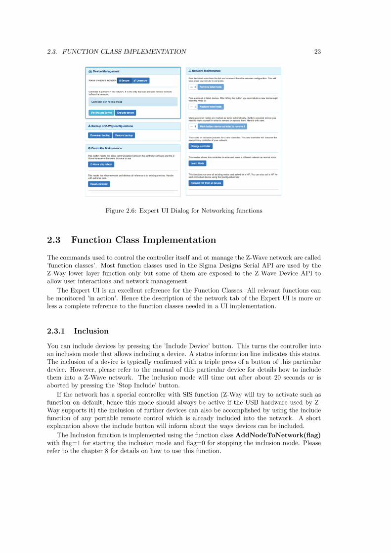
Figure 2.6: Expert UI Dialog for Networking functions
2.3 Function Class Implementation
The commands used to control the controller itself and ot manage the Z-Wave network are called’function classes’. Most function classes used in the Sigma Designs Serial API are used by theZ-Way lower layer function only but some of them are exposed to the Z-Wave Device API toallow user interactions and network management.
The Expert UI is an excellent reference for the Function Classes. All relevant functions canbe monitored ’in action’. Hence the description of the network tab of the Expert UI is more orless a complete reference to the function classes needed in a UI implementation.
2.3.1 Inclusion
You can include devices by pressing the ’Include Device’ button. This turns the controller intoan inclusion mode that allows including a device. A status information line indicates this status.The inclusion of a device is typically confirmed with a triple press of a button of this particulardevice. However, please refer to the manual of this particular device for details how to includethem into a Z-Wave network. The inclusion mode will time out after about 20 seconds or isaborted by pressing the ’Stop Include’ button.
If the network has a special controller with SIS function (Z-Way will try to activate such asfunction on default, hence this mode should always be active if the USB hardware used by Z-Way supports it) the inclusion of further devices can also be accomplished by using the includefunction of any portable remote control which is already included into the network. A shortexplanation above the include button will inform about the ways devices can be included.
The Inclusion function is implemented using the function class AddNodeToNetwork(flag)with flag=1 for starting the inclusion mode and flag=0 for stopping the inclusion mode. Pleaserefer to the chapter 8 for details on how to use this function.
24 CHAPTER 2. THE Z-WAVE DEVICE API
2.3.2 Exclusion
You can exclude devices by pressing the ’Exclude Device’ button. This turns the controllerinto an exclusion mode that allows excluding a device. The exclusion of a device is typicallyconfirmed with a triple press of a button of this particular device as well. However, please refer tothe manual of this device for details how to exclude them into a Z-Wave network. The exclusionmode will time out after about 20 seconds or is aborted by pressing the ’Stop Exclude’ button.It is possible to exclude all kind of devices regardless if they were included in the particularnetwork of the excluding controller.
If a node is not longer in operation it cant be excluded from the network since exclusion needssome confirmation from the device. Please use the ’Remove Failed Node’ function in this case.Please make sure that only failed nodes are moved this way. Removed but still function nodes -called phantom nodes will harm the network stability.
The Exclusion function is implemented using the function class RemoveNodeToNetwork(flag)with flag=1 for starting the exclusion mode and flag=0 for stopping the exclusion mode. Pleaserefer to the chapter 8 for details on how to use this function.
2.3.3 Mark Battery powered devices as failed
This function allows marking battery-powered devices as failed. Only devices marked as failedcan be excluded from the network without using the exclusion function. Typically multiple failedcommunications with a device result in this marking. Battery powered devices are recognizedas sleeping in the controller and therefore all communication attempts with this device willbe queued until a wakeup notification from this device is received. A faulty battery operateddevice will never send a wakeup notification and hence there is never a communication, whichwould result in a failed node status. Battery operated devices can therefore be manually markedas faulty. Make sure to only mark and subsequently remove devices that are faulty or havedisappeared. A device, which was removed with this operation but is still functioning maycreate malfunctions in the network.
This function is no Function class but sets the internal ’failed’ variable of the device object.
2.3.4 Remove Failed Nodes
Z-Way allows removing a node, if and only if this node was detected as failed by the Z-Wavetransceiver. The network will recognize that communication with a device fails multiple timesand the device cant be reached using alternating routes either. The controller will then markthe device as ’failed’ but will keep it in the current network configuration. Any successfulcommunication with the device will remove the failed mark. Only devices marked as failed canbe removed using the ’Remove Failed Node’ function.
If you want to remove a node that is in operation use the ’Exclude’ Function.
This function is implemented using the function class RemoveFailedNode(node id) withnode id as the node id of the device to be removed. Please refer to the chapter 8 for details onhow to use this function. It is also possible to replace a failed node by a new node using thefunction class RemoveFailedNode(node id). Please refer to the chapter 8 for details too.
The function IsFailedNode(node id) can be used to detect if a certain node is failed. TheZ-Wave transceiver will try to contact the device wirelessly and will then update the failed-statusinside the transceiver and also the ’is failed’ flag of the device object in Z-Way.
2.3. FUNCTION CLASS IMPLEMENTATION 25
2.3.5 Include into different network
Z-Way can join a Z-Wave network as secondary controller. It will change its own Home ID tothe Home ID of the new network and it will learn all network information from the includingcontroller of the new network. To join a different network, the primary controller of this newnetwork need to be in the inclusion mode.
Z-Way needs to be turned into the so called learn mode using the button ’Start Include inothers network’. The button Stop Include in others network can be used to turn off the Learnmode, which will time out otherwise or will stop if the learning was successful.
Please be aware that all existing relationships to existing nodes will get lost when theZ-Way controller joins a different network. Hence it is recommended to join a different networkonly after a reset with no other nodes already included.
The ’Learn’ function is implemented using the function class SetLearnMode(flag) withflag=1 for starting the learn mode and flag =0 for stopping the learn mode. Please refer to thechapter 8 for details on how to use this function.
2.3.6 Z-Wave chip reboot
This function will perform a soft restart of the firmware of the Z-Wave controller chip withoutdeleting any network information or setting. It may be necessary to recover the chip from afreezing state. A typical situation of a required chip reboot is if the Z-Wave chip fails to comeback from the inclusion or exclusion state.
The reboot function is implemented using the function class SerialAPISoftReset(). Pleaserefer to the chapter 8 for details on how to use this function.
2.3.7 Request NIF from all devices
This function will call the Node Information Frame from all devices in the network. This maybe needed in case of a hardware change or when all devices where included with a portable USBstick such as e.g. Aeon Labs Z-Stick. Mains powered devices will return their NIF immediately,battery operated devices will respond after the next wakeup.
This function controls a Z-Way controller function that will send out a function class Re-questNodeInformation(node) to all nodes in the network. The function can also be calledfor one single node only. Please refer to the chapter 8 for details on how to use this function.
2.3.8 Send controllers NIF
In certain network configurations it may be required to send out the Node Information Frame ofthe Z-Way controller. This is particularly useful for some some remote controls scene activationfunction. The manual of the remote control will refer to this requirement and give furtherinformation when and how to use this function.
This function is implemented with the function class SerialAPIApplicationNodeInfo withplenty of parameters. These parameters are partly set by Z-Way but particularly the Commandclasses supported (parameter ’NIF’) can be changed by editing the file defaults.xml. Please referto the chapter 8 for details on how to use this function the chapter about the translation files onhow to change defaults.xml
26 CHAPTER 2. THE Z-WAVE DEVICE API
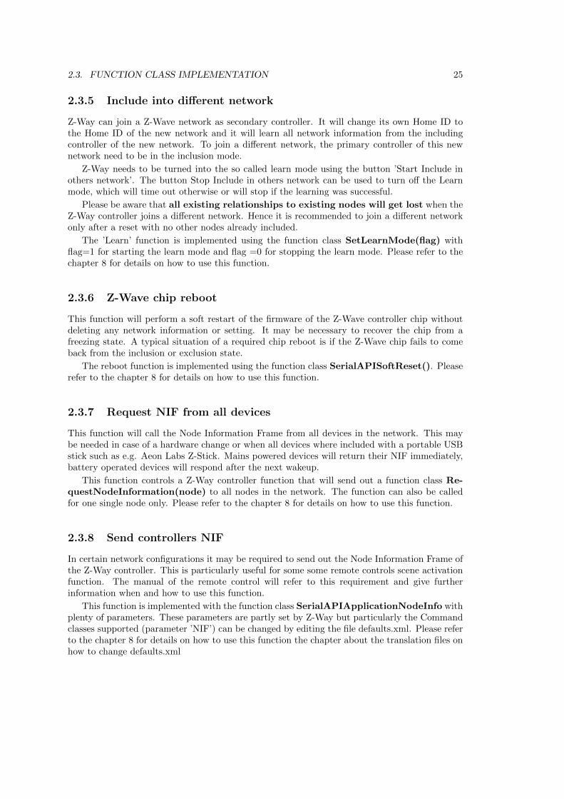
Figure 2.7: Demo UI dialog for Routing Table
2.3.9 Reset Controller
The network configuration (assigned node Ids and the routing table and some other networkmanagement specific parameters) is stored in the Z-Wave transceiver chip and will thereforeeven survive a complete reinstallation of the Z-Way software.
The function ’Reset Controller’ erases all values stored in the Z-Wave chip and sent the chipback to factory defaults. This means that all network information will be lost withoutrecovery option.
This function is implemented with the function class SetDefault(). Please refer to thechapter 8 for details on how to use this function.
2.3.10 Change Controller
The controller change function allows to handover the primary function to a different controller inthe network. The function works like a normal inclusion function but will hand over the primaryprivilege to the new controller after inclusion. Z-Way will become a secondary controller of thenetwork. This function may be needed during installation of larger networks based on remotecontrols only where Z-Way is solely used to do a convenient network setup and the primaryfunction is finally handed over to one of the remote controls.
This function is implemented with the function class ControllerChange(). Please refer tothe chapter 8 for details on how to use this function.
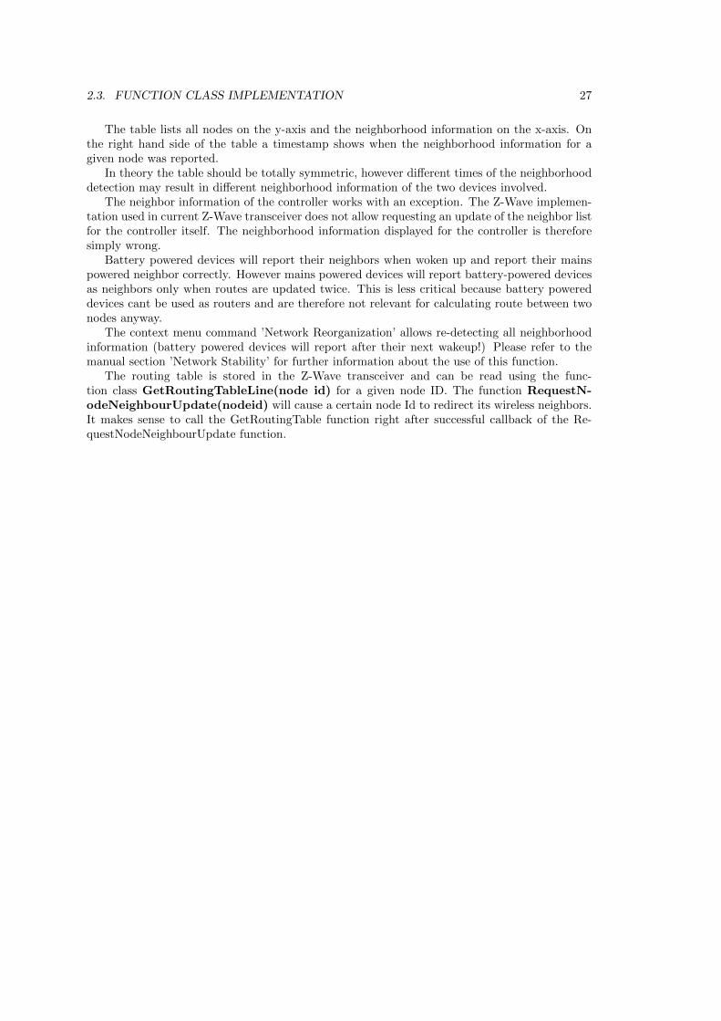
2.3.11 Routing Table
The routing table of the Z-Wave network is shown in the tab network as well. It indicates howtwo devices of the Z-Wave network can communicate with each other. If two devices are in directrange (they can communicate without the help of any other node) the cross point of the twodevices in the table is marked as dark green. The color light green indicates that the two nodesare not in direct range but have more than one alternating routes with one node between. Thisis still considered as a stable connection. The yellow color indicates that there are less than twoone-hop routes available between the two nodes. However there may be more routes but withmore nodes between and therefore considered as less stable.
A red indicator shows that there are no good short connections between the two nodes. Thisdoes not mean that they are unable to communicate with each other but any route with morethan 2 routers between Z-Way is considering as not reliable, even taking into account that Z-Wave supports routes with up to four devices between. Grey cells indicate the connection to theown Node ID.
The general rule of thumb is: ’The greener the better’.
2.3. FUNCTION CLASS IMPLEMENTATION 27
The table lists all nodes on the y-axis and the neighborhood information on the x-axis. Onthe right hand side of the table a timestamp shows when the neighborhood information for agiven node was reported.
In theory the table should be totally symmetric, however different times of the neighborhooddetection may result in different neighborhood information of the two devices involved.
The neighbor information of the controller works with an exception. The Z-Wave implemen-tation used in current Z-Wave transceiver does not allow requesting an update of the neighbor listfor the controller itself. The neighborhood information displayed for the controller is thereforesimply wrong.
Battery powered devices will report their neighbors when woken up and report their mainspowered neighbor correctly. However mains powered devices will report battery-powered devicesas neighbors only when routes are updated twice. This is less critical because battery powereddevices cant be used as routers and are therefore not relevant for calculating route between twonodes anyway.
The context menu command ’Network Reorganization’ allows re-detecting all neighborhoodinformation (battery powered devices will report after their next wakeup!) Please refer to themanual section ’Network Stability’ for further information about the use of this function.
The routing table is stored in the Z-Wave transceiver and can be read using the func-tion class GetRoutingTableLine(node id) for a given node ID. The function RequestN-odeNeighbourUpdate(nodeid) will cause a certain node Id to redirect its wireless neighbors.It makes sense to call the GetRoutingTable function right after successful callback of the Re-questNodeNeighbourUpdate function.
28 CHAPTER 2. THE Z-WAVE DEVICE API
2.4 JSON-API
JSON API allows to execute commands on server side using HTTP POST requests (currentlyGET requests are also allowed, but this might be deprecated in future). The command to executeis taken from the URL.
All functions are executed in form
http://YOURIP:8083/<URL>
2.4.1 /ZWaveAPI/Run/<command>
This executes zway.<command> in JavaScript engine of the server. As an example to switchON a device no 2 using the command class BASIC (The ID of the command class BASIC is0x20, for more information about the IDs of certain command classes please refer to the Annex)its possible to write:
/ZWaveAPI/Run/devices[2].instances[0].commandClasses[0x20].Set(255)
or
/ZWaveAPI/Run/devices[2].instances[0].Basic.Set(255)
The Z-Way Expert GUI has a JavaScript command runCmd(<command>) to simplify suchoperations. This function is accessable in the Javascript console of your web browser (in Chromeyou find the JavaScript console unter View->Debug->JS Console). Using this feature the com-mand in JS console would look like
runCmd(’devices[2].instances[0].Basic.Set(255)’)
The usual way to access a command class is using the format’devices[nodeId].instances[instanceId]. commandClasses[commandclassId]’. There are ways tosimplify the syntax:
• ’devices[nodeId].instances[instanceId].Basic’ is equivalent to’devices[nodeId].instances[instanceId].commandClasses[0x20]’
• the instances[0] can be obmitted: ’devices[nodeId].instances[instanceId].Basic’ then turnsinto ’devices[nodeId].Basic’
Each Instance object has a device property that refers to the parent device it belongs to.Each Command Class Object has a device and an instance property that refers to the instanceand the device this command class belongs to.
Data holder object have properties value, updateTime, invalidateTime, name, but for com-patibility with JS and previous versions we have valueOf() method (allows to omit .value inJS code, hence write ”data.level == 255”), updated (alias to updateTime), invalidated (aliastoinvalidateTime). These aliases are not enumerated if the dataholder is requested (data.levelreturns value: 255, name: ”level”, updatedTime: 12345678, invalidatedTime: 12345678).
2.4.2 /ZWaveAPI/InspectQueue
This function is used to visualize the Z-Way job queue. This is for debugging only but veryuseful to understand the current state of Z-Way engine.
2.4. JSON-API 29
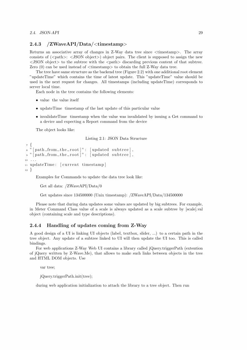
2.4.3 /ZWaveAPI/Data/<timestamp>
Returns an associative array of changes in Z-Way data tree since <timestamp>. The arrayconsists of (<path>: <JSON object>) object pairs. The client is supposed to assign the new<JSON object> to the subtree with the <path> discarding previous content of that subtree.Zero (0) can be used instead of <timestamp> to obtain the full Z-Way data tree.
The tree have same structure as the backend tree (Figure 2.2) with one additional root element”updateTime” which contains the time of latest update. This ”updateTime” value should beused in the next request for changes. All timestamps (including updateTime) corresponds toserver local time.
Each node in the tree contains the following elements:
• value the value itself
• updateTime timestamp of the last update of this particular value
• invalidateTime timestamp when the value was invalidated by issuing a Get command toa device and expecting a Report command from the device
The object looks like:
Listing 2.1: JSON Data Structure
7 {8 ” [ path from the root ] ” : [ updated subt ree ] ,9 ” [ path from the root ] ” : [ updated subt ree ] ,
10 . . .11 updateTime : [ cur rent timestamp ]12 }
Examples for Commands to update the data tree look like:
Get all data: /ZWaveAPI/Data/0
Get updates since 134500000 (Unix timestamp): /ZWaveAPI/Data/134500000
Please note that during data updates some values are updated by big subtrees. For example,in Meter Command Class value of a scale is always updated as a scale subtree by [scale].valobject (containing scale and type descriptions).
2.4.4 Handling of updates coming from Z-Way
A good design of a UI is linking UI objects (label, textbox, slider, ...) to a certain path in thetree object. Any update of a subtree linked to UI will then update the UI too. This is calledbindings.
For web applications Z-Way Web UI contains a library called jQuery.triggerPath (extentionof jQuery written by Z-Wave.Me), that allows to make such links between objects in the treeand HTML DOM objects. Use
var tree;
jQuery.triggerPath.init(tree);
during web application initialization to attach the library to a tree object. Then run

30 CHAPTER 2. THE Z-WAVE DEVICE API
jQuery([objects selector]).bindPath([path with regexp], [updater function], [additionalarguments]);
to make binding between path changes and updater function. The updater function wouldbe called upon changes in the desired object with this pointing to the DOM object itself, firstargument pointing to the updated object in the tree, second argument is the exact path of thisobject (fulfilling the regexp) and all other arguments copies additional arguments. RegExp allowsonly few control characters: * is a wildcard, (1—2—3) - is 1 or 2 or 3.
Please not that the use of the triggerpath extension is one option to handle theincoming data. You can also extract all the interesting values right when the datais received and bind update functions to them.
2.5. COMMAND CLASS IMPLEMENTATION 31
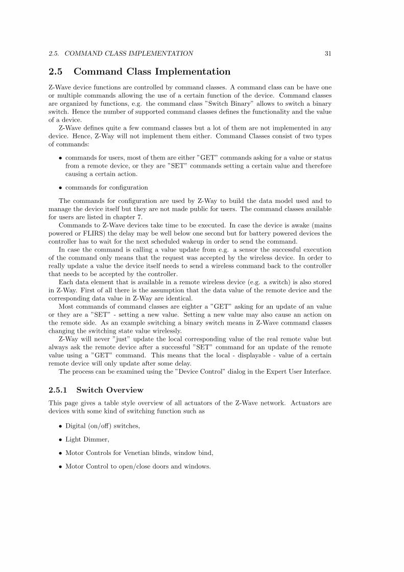
2.5 Command Class Implementation
Z-Wave device functions are controlled by command classes. A command class can be have oneor multiple commands allowing the use of a certain function of the device. Command classesare organized by functions, e.g. the command class ”Switch Binary” allows to switch a binaryswitch. Hence the number of supported command classes defines the functionality and the valueof a device.
Z-Wave defines quite a few command classes but a lot of them are not implemented in anydevice. Hence, Z-Way will not implement them either. Command Classes consist of two typesof commands:
• commands for users, most of them are either ”GET” commands asking for a value or statusfrom a remote device, or they are ”SET” commands setting a certain value and thereforecausing a certain action.
• commands for configuration
The commands for configuration are used by Z-Way to build the data model used and tomanage the device itself but they are not made public for users. The command classes availablefor users are listed in chapter 7.
Commands to Z-Wave devices take time to be executed. In case the device is awake (mainspowered or FLIRS) the delay may be well below one second but for battery powered devices thecontroller has to wait for the next scheduled wakeup in order to send the command.
In case the command is calling a value update from e.g. a sensor the successful executionof the command only means that the request was accepted by the wireless device. In order toreally update a value the device itself needs to send a wireless command back to the controllerthat needs to be accepted by the controller.
Each data element that is available in a remote wireless device (e.g. a switch) is also storedin Z-Way. First of all there is the assumption that the data value of the remote device and thecorresponding data value in Z-Way are identical.
Most commands of command classes are eighter a ”GET” asking for an update of an valueor they are a ”SET” - setting a new value. Setting a new value may also cause an action onthe remote side. As an example switching a binary switch means in Z-Wave command classeschanging the switching state value wirelessly.
Z-Way will never ”just” update the local corresponding value of the real remote value butalways ask the remote device after a successful ”SET” command for an update of the remotevalue using a ”GET” command. This means that the local - displayable - value of a certainremote device will only update after some delay.
The process can be examined using the ”Device Control” dialog in the Expert User Interface.
2.5.1 Switch Overview
This page gives a table style overview of all actuators of the Z-Wave network. Actuators aredevices with some kind of switching function such as
• Digital (on/off) switches,
• Light Dimmer,
• Motor Controls for Venetian blinds, window bind,
• Motor Control to open/close doors and windows.
32 CHAPTER 2. THE Z-WAVE DEVICE API
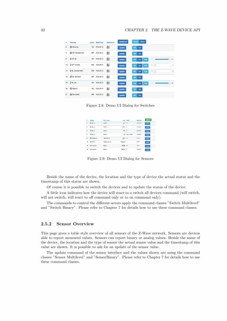
Figure 2.8: Demo UI Dialog for Switches
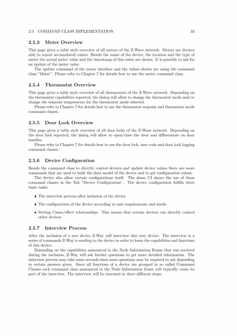
Figure 2.9: Demo UI Dialog for Sensors
Beside the name of the device, the location and the type of device the actual status and thetimestamp of this status are shown.
Of course it is possible to switch the devices and to update the status of the device.
A little icon indicates how the device will react to a switch all devices command (will switch,will not switch, will react to off command only or to on command only).
The commands to control the different actors apply the command classes ”Switch Multilevel”and ”Switch Binary”. Please refer to Chapter 7 for details how to use these command classes.
2.5.2 Sensor Overview
This page gives a table style overview of all sensors of the Z-Wave network. Sensors are devicesable to report measured values. Sensors can report binary or analog values. Beside the name ofthe device, the location and the type of sensor the actual sensor value and the timestamp of thisvalue are shown. It is possible to ask for an update of the sensor value.
The update command of the sensor interface and the values shown are using the commandclasses ”Sensor Multilevel” and ”SensorBinary”. Please refer to Chapter 7 for details how to usethese command classes.
2.5. COMMAND CLASS IMPLEMENTATION 33
2.5.3 Meter Overview
This page gives a table style overview of all meters of the Z-Wave network. Meters are devicesable to report accumulated values. Beside the name of the device, the location and the type ofmeter the actual meter value and the timestamp of this value are shown. It is possible to ask foran update of the meter value.
The update command of the meter interface and the values shown are using the commandclass ”Meter”. Please refer to Chapter 7 for details how to use the meter command class.
2.5.4 Thermostat Overview
This page gives a table style overview of all thermostats of the Z-Wave network. Depending onthe thermostat capabilities reported, the dialog will allow to change the thermostat mode and/orchange the setpoint temperature for the thermostat mode selected.
Please refer to Chapter 7 for details how to use the thermostat setpoint and thermostat modecommand classes.
2.5.5 Door Lock Overview
This page gives a table style overview of all door locks of the Z-Wave network. Depending onthe door lock reported, the dialog will allow to open/close the door and differentiate on doorhandles.
Please refer to Chapter 7 for details how to use the door lock, user code and door lock loggingcommand classes.
2.5.6 Device Configuration
Beside the command class to directly control devices and update device values there are morecommands that are used to built the data model of the device and to get configuration values.
The device also allow certain configurations itself. The demo UI shows the use of thesecommand classes in the Tab ”Device Configuration”. The device configuration fulfills threebasic tasks:
• The interview process after inclusion of the device
• The configuration of the device according to user requirements and needs.
• Setting Cause/effect relationships. This means that certain devices can directly controlother devices.
2.5.7 Interview Process
After the inclusion of a new device Z-Way will interview this very device. The interview is aseries of commands Z-Way is sending to the device in order to learn the capabilities and functionsof this device.
Depending on the capabilities announced in the Node Information Frame that was receivedduring the inclusion, Z-Way will ask further questions to get more detailed information. Theinterview process may take some seconds since more questions may be required to ask dependingin certain answers given. Since all functions of a device are grouped in so called CommandClasses each command class announced in the Node Information frame will typically cause itspart of the interview. The interview will be executed in three different steps:
34 CHAPTER 2. THE Z-WAVE DEVICE API
1. In case there is a Version Command Class ask for the Version of the device and the versionsof all Command Classes announced in the Node Information frame. Otherwise Version 1is assumed.
2. In case there is a Multi Channel Command class announced, ask for the number of thecapabilities of the different channels and repeat Step 3 for each channel.
3. Ask for all capabilities of all command classes.
4. Do some auto configurations if needed.
The Device Status tab will indicate if the interview was successfully completed. The blueinformation icon shows if the interview was not complete. Clicking on this icon opens a dialogwith all command classes and the status of their respective interviews. A complete interview isimportant in order to have access to all functions of the device included. Incomplete interviewsmay also be a reason for malfunctions of the network. There are several reasons why an interviewmay not be completed.
1. A battery-operated device may be gone into sleep mode too early. In this case it is possibleto wake up the device manually to complete the interview. Sometimes manual wakeup isneeded several times.
2. The device does not fully comply with the Z-Wave protocol. This is particularly possiblefor devices that were brought to market before 2008. The current more sophisticatedcertification process makes sure that devices are 100% compatible to the Z-Wave productwhen they hit the market. Please check online ressources on wikis and forums for furtherdetails and possible ways to fix these kinds of problems.
3. The device does not have a reliable communication route to the controller. Interview com-munication typically use longer packets than normal polling communication. This makesthe interview communication more vulnerable against weak and instable communicationlinks. Its possible that the controller is able to include a device and even receive confirma-tion of a polling request but still not being able to complete the interview. However this isa rare case.
4. The device may be simply broken.
Most of the command exchange during interview is using commands dedicated for the inter-view process. They are not exposed on the API.
2.5.8 Device Configuration
Each Z-Wave device is designed to work out of the box after inclusion without further configu-ration. However, it may be suitable and in certain contexts even required to do a device specificconfigurations.
The device configuration page allows to further configure the device and to access certainadditional information about the device. The tab is grouped into several sections. The sectionscan be toggled from invisible to visible and back by clicking on the headlines:
• Select Z-Wave Device Description Record
• Device Description
• Configurations
2.5. COMMAND CLASS IMPLEMENTATION 35
• Actions with configurations
• Advanced Actions
Select Z-Wave Device Description Record After a successful inclusion Z-Way will inter-view the device to gather further information.
Certain information such as names of association groups, the brand name of the device andthe parameters of further configuration values can not be detected during interview. Z-Wayuses a device database with product description files to obtain this information. In order toidentify the right device description record, certain parameters of the interview are used. Ifthese parameters match exactly one device description record, this very record is loaded and itscontent is shown on the device configuration page automatically.
If the information from the device is sufficient to select one specific record from the databasethis section of the tab is hidden. If it is not possible to identify the correct device descriptionrecord the user can manually choose the correct record. It is also possible to manually changethe selection of the device description by unhiding this section and clicking on the Select DeviceDescription Record button.
Device Description The upper part of the dialog shows some descriptive values of the device.The Z-Wave device type is the only value generated solely from the interview data. All otherdata are taken from the device description record.
• Zone: ... the zone/room the device is assigned to. Will be manually defined in Zone-tab.
• Brand: the product code or brand name of the device. This will be taken from the devicedescription record.
• Device Type: ... the type of Z-Wave device as reported by the device during inclusion.
• Description: a verbal description of the function. This will be taken from the devicedescription record.
• Interview Stage: shows the progress of the interview process. This information is generatedby Z-Way.
• Inclusion Note: how to (re-) include the device. This will be taken from the devicedescription record.
• Wakeup Note: this will be taken from the device description record.
• Documents: If the device description record offers links to manuals or other online docu-ments there are shown here. This will be taken from the device description record.
• Device State: Status of the device plus number of packets queued for this device
There are a couple of reasons why no device description record was found:
1. There is no record for the device available. Since there are always new devices on themarket Z-Way needs to catch up and update its device database. If your device is notfound, updating to the most recent version of Z-Way may help.
36 CHAPTER 2. THE Z-WAVE DEVICE API
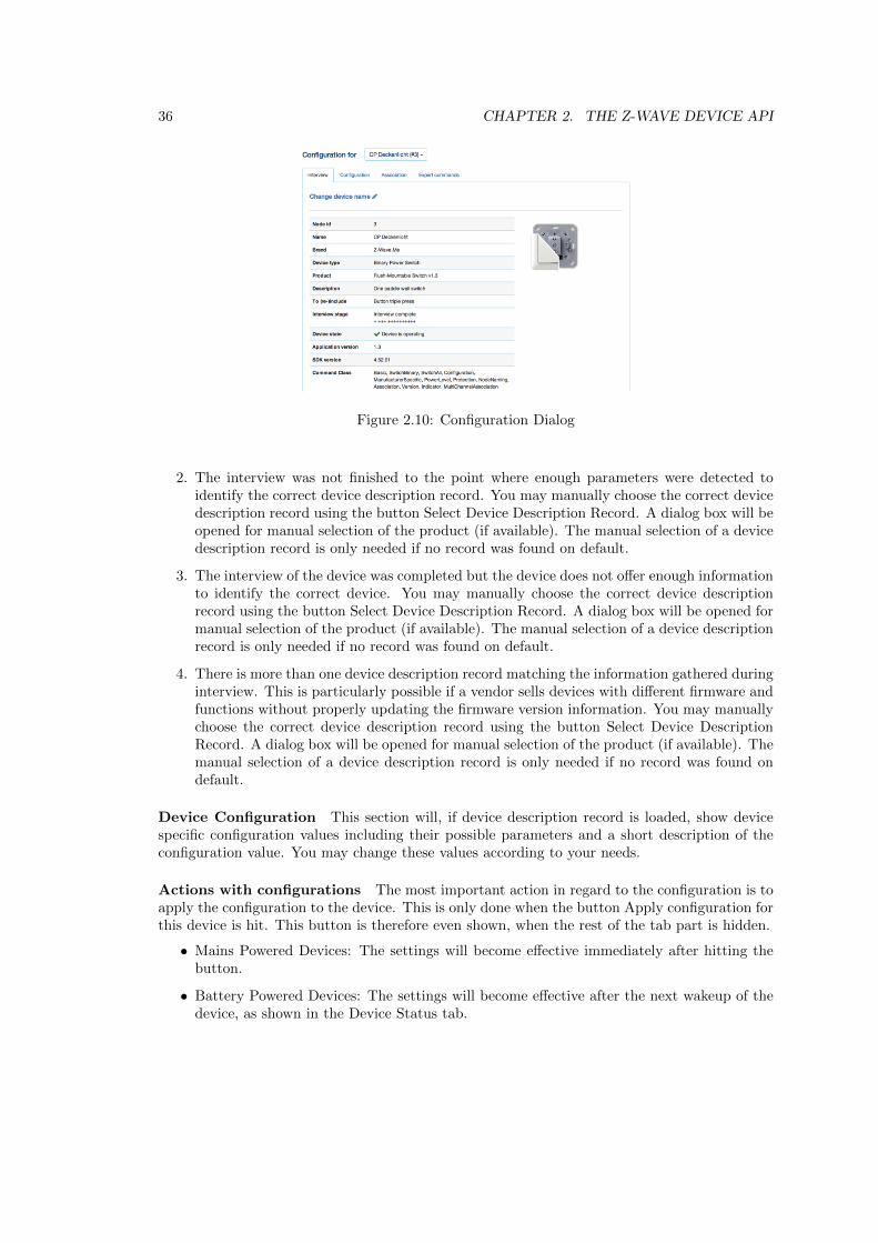
Figure 2.10: Configuration Dialog
2. The interview was not finished to the point where enough parameters were detected toidentify the correct device description record. You may manually choose the correct devicedescription record using the button Select Device Description Record. A dialog box will beopened for manual selection of the product (if available). The manual selection of a devicedescription record is only needed if no record was found on default.
3. The interview of the device was completed but the device does not offer enough informationto identify the correct device. You may manually choose the correct device descriptionrecord using the button Select Device Description Record. A dialog box will be opened formanual selection of the product (if available). The manual selection of a device descriptionrecord is only needed if no record was found on default.
4. There is more than one device description record matching the information gathered duringinterview. This is particularly possible if a vendor sells devices with different firmware andfunctions without properly updating the firmware version information. You may manuallychoose the correct device description record using the button Select Device DescriptionRecord. A dialog box will be opened for manual selection of the product (if available). Themanual selection of a device description record is only needed if no record was found ondefault.
Device Configuration This section will, if device description record is loaded, show devicespecific configuration values including their possible parameters and a short description of theconfiguration value. You may change these values according to your needs.
Actions with configurations The most important action in regard to the configuration is toapply the configuration to the device. This is only done when the button Apply configuration forthis device is hit. This button is therefore even shown, when the rest of the tab part is hidden.
• Mains Powered Devices: The settings will become effective immediately after hitting thebutton.
• Battery Powered Devices: The settings will become effective after the next wakeup of thedevice, as shown in the Device Status tab.
2.5. COMMAND CLASS IMPLEMENTATION 37
• Battery Powered Controllers (remote controls or wall controllers): The settings will onlybecome effective if the devices are woken up manually. Refer to the controller manual formore information on how to wake up the device. Appendix B may also give further advice.
If there are many similar devices in a network, it is desirable to just apply one workingconfiguration to all these devices. This can be done using the function ’Copy from other Device’.
The set of defined configuration values is stored for every device. Therefore its possible topick a different device and reuse its configuration values for the device to be configured. TheSave function of the bottom context menu allows saving the configuration for further use andreuse.
Actions with configurations This function requests the selected device to send its NodeInformation frame (NIF) to the controller. It can be used instead of triple pressing a button onthe device itself that would also instruct the device to send it NIF. The NIF is needed to knowdevice capabilities.
Delete Configuration of this device in section Actions with configuration Thisfunction deletes the stored configuration for this device. This function is for debugging purposesonly.
Force Interview in section Advanced This functions forces to redo the whole interview.All previous interview data will be deleted. This function is for debugging purposes only.
Show Interview Results in section Advanced This function shows the result of theinterview. This function is for debugging purposes only. For information about reasons forincomplete interview please refer to the manual section Device Status.
The bottom context menu function Reset Configuration deletes all configurations stored inZ-Way, but does not affect devices!
The configuration dialog documents the use of the command classes ”Association”, ”Protec-tion”, ”Configuration” and ”Switch All”.
2.5.9 Associations
If there was no previous device of the same type installed, the interface will show the values asread from the device. If there was already a device of the same kind installed, there may exist astored default configuration for this particular device. Then the setup in the device may differfrom the default configuration stored in Z-Way.
• Gray Icon: This Node ID is stored in the device but its not stored in the default config-uration of the Z-Way. You can double click this device to store this setting in the Z-Waydefault configuration of this device type.
• Red Icon: This Node ID is stored locally but not in the association group of the device yet.Apply the settings to transmit the setting into the device. In case of a battery operateddevice you need to wakeup the device in order to store the configuration.
• Black Icon: This Node ID is stored both in the device and in the local configuration ofZ-Way.

38 CHAPTER 2. THE Z-WAVE DEVICE API
Hint: The auto configuration function of Z-Way will place the node ID of the Z-Way controllerin all association groups if possible. This allows the activation of scenes from these devices.
All management of Associations is handled by the command class ”Association”, In case thetarget device is a multi channel device the command class ”Multi Channel Association” is used.Please refer to chapter 7 for details how to use these command classes.
Chapter 3
JavaScript API
The JavaScript API mirrors all functions of the Z-Wave device API and combines them with theability to run JavaScript code on top of the Z-Wave Device functions and variables.
There are two ways to run JavaScript functions in Z-Way.
• They can be executed in the web browser URL string (using /JS/Run/ prefix)
• They can be implemented as module running in the backend or be stored in a file on theserver side.
Both options have their pros and cons. Running JS code in the browser is a very nice andconvenient way to test things but the function is not persistent.
Writing a module requires some more knowledge and debugging is more complicated. On theother hand the possibilities of JavaScript in the module are almost infinite and goes far beyondjust accessing Z-Wave device. JavaScript as any other language can make use of services availablein the Internet and combine them in any possible way with information from the Z-Wave networkand can execute functions within the Z-Wave network but the same time on any place accessiblevia Internet based services. In theory there is not even a need to have Z-Wave device in order tomake use of the powerful JavaScript engine. As an example you can write a JavaScript modulepolling weather data from the internet and depending on certain well defined conditions the samemodule can send you a short message on your mobile. Both functions are by the way alreadyimplemented as open source modules and can be accessed and studied for further modificationor use.
3.1 The JavaScript Engine
Z-Way uses the JavaScript engine provided by Google referred to as V8. You find more informa-tion about this JavaScript implementation on https://code.google.com/p/v8/. V8 implementsJavaScript according to the specification ECMA 5 1.
Z-Way extends the basic functionality provided by V8 with plenty of application specificfunctions.
3.2 Accessing the JS API
The JS API can be accessed from any web browser with the URL
1http://www.ecma-international.org/publications/standards/Ecma-262.htm
39
40 CHAPTER 3. JAVASCRIPT API
http://YOURIP:8083/JS/Run/* All functions of the Z-Wave Device API can be used byJavaScript. They are encapsulated in the ’zway’ object. This object has the same structure asdefined in chapter ??. The client side access to the device data is done like
http://YOURIP:8083/JS/Run/zway.devices[x].* Due to the scripting nature of JavaScriptits possible to ’inject’ code at run time using the interface. Here a nice example how to use theJava Script setInterval function:
Listing 3.1: Polling device #2
13 /JS/Run/ s e t I n t e r v a l ( func t i on ( ) {14 zway . d ev i c e s [ 2 ] . Bas ic . Get ( ) ;15 } , 300∗1000) ;
This code will, once ’executed’ as URL within a web browser, call the Get() command of thecommand class Basic of Node ID 2 every 300 seconds.
A very powerful function of the JS API is the ability to bind functions to certain valuesof the device tree. they get then executed when the value changes. Here an example for thisbinding. The device No. 3 has a command class SensorMultilevel that offers the variable level.The following call - both available on the client side and on the server side - will bind a simplealert function to the change of the variable.
Listing 3.2: Bind a function
16 zway . d ev i c e s [ 3 ] . S e n s o r M u l t i l e v e l . data [ 1 ] . l e v e l . bind ( func t i on ( ) {17 debugPrint ( ’CHANGED TO: ’ + t h i s . va lue + ’ \n ’ ) ;18 } ) ;
3.3 HTTP Access
The JavaScript implementation of Z-Way allows to directly accessing HTTP objects.The http request is much like jQuery.ajax(): r = http.request(options);Here’s the list of options:
• url - required. Url you want to request (might be http, https, or maybe even ftp);
• method optional. HTTP method to use (currently one of GET, POST, HEAD). If notspecified, GET is used;
• headers optional. Object containing additional headers to pass to server:
1 headers : {2 ”Content−Type” : ” t ext /xml” ,3 ”X−Requested−With” : ”RaZberry / 1 . 5 . 0 ”4 }
• data used only for POST requests. Data to post to the server. May be either a string (topost raw data) or an object with keys and values (will be serialized as ’key1=value1&key2=value2&’);
• auth optional. Provides credentials for basic authentication. It is an object containinglogin and password:
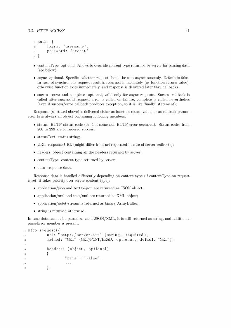
3.3. HTTP ACCESS 41
1 auth : {2 l o g i n : ’ username ’ ,3 password : ’ s e c r e t ’4 }
• contentType optional. Allows to override content type returned by server for parsing data(see below);
• async optional. Specifies whether request should be sent asynchronously. Default is false.In case of synchronous request result is returned immediately (as function return value),otherwise function exits immediately, and response is delivered later thru callbacks.
• success, error and complete optional, valid only for async requests. Success callback iscalled after successful request, error is called on failure, complete is called nevertheless(even if success/error callback produces exception, so it is like ’finally’ statement);
Response (as stated above) is delivered either as function return value, or as callback param-eter. Is is always an object containing following members:
• status HTTP status code (or -1 if some non-HTTP error occurred). Status codes from200 to 299 are considered success;
• statusText status string;
• URL response URL (might differ from url requested in case of server redirects);
• headers object containing all the headers returned by server;
• contentType content type returned by server;
• data response data.
Response data is handled differently depending on content type (if contentType on requestis set, it takes priority over server content type):
• application/json and text/x-json are returned as JSON object;
• application/xml and text/xml are returned as XML object;
• application/octet-stream is returned as binary ArrayBuffer;
• string is returned otherwise.
In case data cannot be parsed as valid JSON/XML, it is still returned as string, and additionalparseError member is present.
1 http . r eque s t ({2 u r l : ” http :// s e r v e r . com” ( s t r i ng , r equ i r ed ) ,3 method : ”GET” (GET/POST/HEAD, opt iona l , default ”GET” ) ,4
5 headers : ( object , op t i ona l )6 {7 ”name” : ” va lue ” ,8 . . .9 } ,
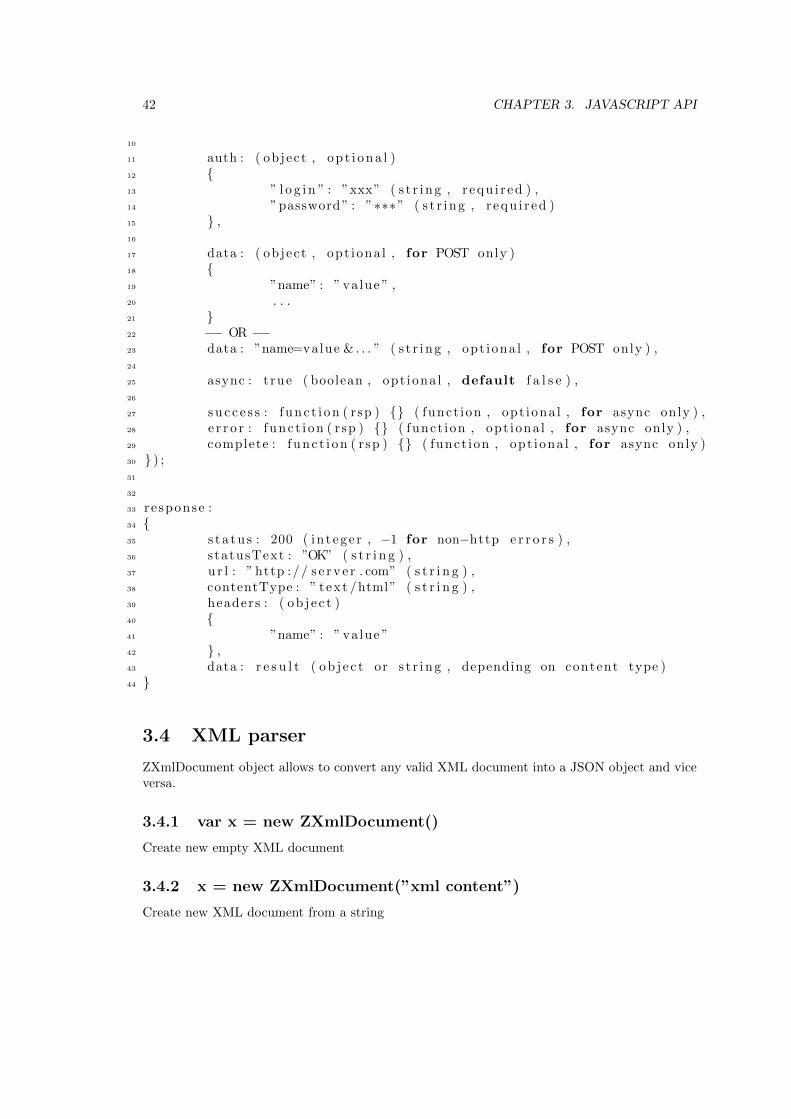
42 CHAPTER 3. JAVASCRIPT API
10
11 auth : ( object , op t i ona l )12 {13 ” l o g i n ” : ”xxx” ( s t r i ng , r equ i r ed ) ,14 ”password” : ”∗∗∗” ( s t r i ng , r equ i r ed )15 } ,16
17 data : ( object , opt iona l , for POST only )18 {19 ”name” : ” va lue ” ,20 . . .21 }22 −− OR −−23 data : ”name=value & . . . ” ( s t r i ng , opt iona l , for POST only ) ,24
25 async : t rue ( boolean , opt iona l , default f a l s e ) ,26
27 s u c c e s s : f unc t i on ( rsp ) {} ( funct ion , opt iona l , for async only ) ,28 e r r o r : f unc t i on ( rsp ) {} ( funct ion , opt iona l , for async only ) ,29 complete : f unc t i on ( rsp ) {} ( funct ion , opt iona l , for async only )30 } ) ;31
32
33 re sponse :34 {35 s t a t u s : 200 ( in t ege r , −1 for non−http e r r o r s ) ,36 s tatusText : ”OK” ( s t r i n g ) ,37 u r l : ” http :// s e r v e r . com” ( s t r i n g ) ,38 contentType : ” t ext /html” ( s t r i n g ) ,39 headers : ( ob j e c t )40 {41 ”name” : ” va lue ”42 } ,43 data : r e s u l t ( ob j e c t or s t r i ng , depending on content type )44 }
3.4 XML parser
ZXmlDocument object allows to convert any valid XML document into a JSON object and viceversa.
3.4.1 var x = new ZXmlDocument()
Create new empty XML document
3.4.2 x = new ZXmlDocument(”xml content”)
Create new XML document from a string
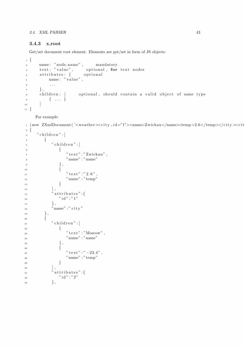
3.4. XML PARSER 43
3.4.3 x.root
Get/set document root element. Elements are got/set in form of JS objects:
1 {2 name : ”node name” , mandatory3 t ex t : ” va lue ” , opt iona l , for t ex t nodes4 a t t r i b u t e s : { op t i on a l5 name : ” value ” ,6 . . .7 } ,8 c h i l d r e n : [ opt iona l , should conta in a v a l i d ob j e c t o f same type9 { . . . }
10 ]11 }
For example:
1 (new ZXmlDocument( ’<weather><c i t y id=”1”><name>Zwickau</name><temp>2.6</temp></c i ty><c i t y id=”2”><name>Moscow</name><temp>−23.4</temp></c i ty ></weather> ’ ) ) . root =2 {3 ” c h i l d r e n ” : [4 {5 ” c h i l d r e n ” : [6 {7 ” text ” : ”Zwickau” ,8 ”name” : ”name”9 } ,
10 {11 ” text ” : ” 2 . 6 ” ,12 ”name” : ”temp”13 }14 ] ,15 ” a t t r i b u t e s ” :{16 ” id ” : ”1”17 } ,18 ”name” : ” c i t y ”19 } ,20 {21 ” c h i l d r e n ” : [22 {23 ” text ” : ”Moscow” ,24 ”name” : ”name”25 } ,26 {27 ” text ” : ”−23.4” ,28 ”name” : ”temp”29 }30 ] ,31 ” a t t r i b u t e s ” :{32 ” id ” : ”2”33 } ,
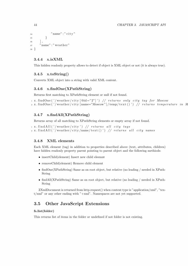
44 CHAPTER 3. JAVASCRIPT API
34 ”name” : ” c i t y ”35 }36 ] ,37 ”name” : ” weather ”38 }
3.4.4 x.isXML
This hidden readonly property allows to detect if object is XML object or not (it is always true).
3.4.5 x.toString()
Converts XML object into a string with valid XML content.
3.4.6 x.findOne(XPathString)
Returns first matching to XPathString element or null if not found.
1 x . findOne ( ’ / weather / c i t y [ @id=”2”] ’ ) // re turns on ly c i t y tag f o r Moscow2 x . findOne ( ’ / weather / c i t y [ name=”Moscow ” ]/ temp/ text ( ) ’ ) // re turns temperature in Moscow
3.4.7 x.findAll(XPathString)
Returns array of all matching to XPathString elements or empty array if not found.
1 x . f i n d A l l ( ’ / weather / c i t y ’ ) // re turns a l l c i t y t a g s2 x . f i n d A l l ( ’ / weather / c i t y /name/ text ( ) ’ ) // re turns a l l c i t y names
3.4.8 XML elements
Each XML element (tag) in addition to properties described above (text, attributes, children)have hidden readonly property parent pointing to parent object and the following methiods:
• insertChild(element) Insert new child eleemnt
• removeChild(element) Remove child element
• findOne(XPathString) Same as on root object, but relative (no leading / needed in XPath-String
• findAll(XPathString) Same as on root object, but relative (no leading / needed in XPath-String
ZXmlDocument is returned from http.request() when content type is ”application/xml”, ”tex-t/xml” or any other ending with ”+xml”. Namespaces are not yet supported.
3.5 Other JavaScript Extensions
fs.list(folder)
This returns list of items in the folder or undefined if not folder is not existing.
3.5. OTHER JAVASCRIPT EXTENSIONS 45
fs.stat(file)
This returns one of the following values:
• 1) undefined if object does not exist or not readable
• 2) object { type: ’file’, size: <size>} if it is a file
• 3) object { type: ’dir’ } if it is a folder
fs.loadJSON(filename)
This function reads a file from the file system and loads it into the memory. The file must containa valid JSON object. The only argument is the name of the file including full pathname of thelocal file system. The functions returns the full JSON object or null in case of error.
fs.load(filename)
This function reads a file from the file system and returns it’s content as a string. The onlyargument is the name of the file including full pathname of the local file system. The functionsreturns null in case of error.
executeFile(filename) and executeJS(string)
Loads and executes a particular JavaScript file from the local filesystem or executes JavaScriptcode represented in string (like eval in browsers).
The script is executed withig the global namespace.Remark: If an error occurred during the execution it won’t stop from further execution, but
erroneous script will not be executed completely. It will stop on the first error. Exceptions inthe callee can be trapped in the caller using standard try-catch mechanism.
system(command)
The command system() allows to execute any shell level command available on the operatingsystem. It will return the shell output of the command. On default the execution of systemcommands is forbidden. Each command executed need to be permitted by putting one line withthe starting commands in the file automation/.syscommands or in an different automation folderas specified in config.xml.
Timers
Timers are implemented exactly as they are used in browsers. They are very helpfull for periodicaland delayed operations. Timeout/period is defined in milliseconds.
• timerId = setTimeout(function() , timeout)
• timerId = setInterval(function() , period)
• clearTimeout(timerId)
• clearInterval(timerId)
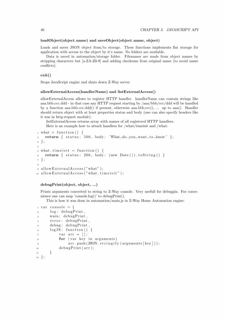
46 CHAPTER 3. JAVASCRIPT API
loadObject(object name) and saveObject(object name, object)
Loads and saves JSON object from/to storage. These functions implements flat storage forapplication with access to the object by it’s name. No folders are available.
Data is saved in automation/storage folder. Filenames are made from object names bystripping characters but [a-ZA-Z0-9] and adding checksum from original name (to avoid nameconflicts).
exit()
Stops JavaScript engine and shuts down Z-Way server
allowExternalAccess(handlerName) and listExternalAccess()
allowExternalAccess allows to register HTTP handler. handlerName can contain strings likeaaa.bbb.ccc.ddd - in that case any HTTP request starting by /aaa/bbb/ccc/ddd will be handledby a function aaa.bbb.ccc.ddd() if present, otherwise aaa.bbb.ccc(), ... up to aaa(). Handlershould return object with at least properties status and body (one can also specify headers likeit was in http.request module).
listExternalAccess returns array with names of all registered HTTP handlers.Here is an example how to attach handlers for /what/timeisit and /what:
1 what = func t i on ( ) {2 return { s t a t u s : 500 , body : ’What do you want to know ’ } ;3 } ;4
5 what . t i m e i s i t = func t i on ( ) {6 return { s t a t u s : 200 , body : (new Date ( ) ) . t oS t r i ng ( ) }7 } ;8
9 a l lowExterna lAcces s ( ”what” ) ;10 a l lowExterna lAcces s ( ”what . t i m e i s i t ” ) ;
debugPrint(object, object, ...)
Prints arguments converted to string to Z-Way console. Very usefull for debuggin. For conve-nience one can map ’console.log()’ to debugPrint().
This is how it was done in automation/main.js in Z-Way Home Automation engine:
1 var conso l e = {2 l og : debugPrint ,3 warn : debugPrint ,4 e r r o r : debugPrint ,5 debug : debugPrint ,6 logJS : func t i on ( ) {7 var ar r = [ ] ;8 for ( var key in arguments )9 ar r . push (JSON. s t r i n g i f y ( arguments [ key ] ) ) ;
10 debugPrint ( a r r ) ;11 }12 } ;
3.5. OTHER JAVASCRIPT EXTENSIONS 47
3.5.1 Debugging JavaScript code
Change in config.xml debug-port to 8183 (or some other) turn on V8 debugger capability onZ-Way start.
1 <con f i g>2 . . .3 <debug−port >8183</debug−port>4 . . . .5 </con f i g>
node-inspector debugger tool is required. It provides web-based UI for debugging similar toGoogle Chrome debug console.
You might want to run debugger tool on another machine (for example if it is not possibleto install it on the same box as Z-Way is running on).
Use the following command to forward debugger port defined in config.xml to your localmachine:
1 ssh −N USER@IP OF Z−WAY MACHINE −L 8 1 8 3 : 1 2 7 . 0 . 0 . 1 : 8 1 8 3
(for RaZberry USER is pi)Install node-inspector debugger tool and run it:
1 npm i n s t a l l −g node−i n s p e c t o r2 node−i n s p e c t o r −−debug−port 8183
Then you can connect to http://IP OF MACHINE WITH NODE INSPECTOR:8080/debug?port=8183If debugging is turned on, Z-Way gives you 5 seconds during startup to reconnect debugger
to Z-Way (refresh the page of debugger Web UI withing these 5 seconds). This allows you todebug startup code of Z-Way JavaScript engine from the very first line of code.

48 CHAPTER 3. JAVASCRIPT API
Chapter 4
The Automation Subsystem
The automation subsystem allows writing automation scripts using Javascript. It uses the ECMAcompatible Javascript Engine described in chapter 3. All the code realizing the automation engineis written in Javascript itself and is available as open source for further study and modification.
The automation engine performs different actions based on events. The actions are eithersignal commands or scripts that can add additional logic and conditions. Events are eithergenerated from the Z-Wave network or from an outside sources such as the Internet or even froma user interaction is causing certain actions, either within the Z-Wave network (e.g. switchinga light) or outside Z-Wave (e.g. sending a email). In Z-Way all automation is organized in socalled modules. The subsequent manual will explain how these modules work and how to createown modules.
Attention: There is no Graphical User Interface for the automation engine atthis moment in time. You will need a text editor such as joe, textwrangler or vi toedit certain files.
4.1 How to get to the automation engine
The starting point for automation in Z-Way is called config.xml and is located in the main folderof Z-Way. The statement for the automation engine looks like
< automation− dir > pathToAutomationCodeBase < /automation− dir >
Assuming the automation is like on default in the subdirectory /automation the statementshould look like
< automation− dir > automation < /automation− dir >
The automation folder consists of several files and subdirectories. The most important fileof the automation is called config.json. This file contains the information about all automationmodules and their instances. This file is automatically generated and should be changed withoutproper knowledge.
4.2 The Event Bus
All communication from and to the automation modules is handled by events. An event is astructure containing certain information that is exchanged using a central distribution place, the
49
50 CHAPTER 4. THE AUTOMATION SUBSYSTEM
event bus. This means that all modules can send events to the event bus and can listen toevent in order to execute commands on them. All modules can ’see’ all events but need to filterout their events of relevance. The core objects of the automation are written in JS and they areavailable as source code in the sub folder ’classes’:
• AutomationController.js: This is the main engine of the automation function
• AutomationModule.js: the basic object for the module
The file main.js is the startup file for the automation system and it is loading the threeclasses just mentioned. The subfolder /lib contains the key JS script for the Event handling:eventemitter.js.
4.2.1 Emitting events
The ’Event emitter’ emits events into the central event bus. The event emitter can be calledfrom all modules and scripts of the automation system. The syntax is:
controller.emit(eventName, args1, arg2, ...argn)
The event name ’eventName’ has to be noted in the form of ’XXX.YYY’ where ’XXX’ is thename of the event source (e.g. the name of the module issuing the event or the name of themodule using the event) and ’YYY’ is the name of the event itself. To allow a scalable systemit makes sense to name the events by the name of the module that is supposed to receive and tomanage events. This simplifies the filtering of these events by the receiver module(s).
Certain event names are forbidden for general use because they are already used in the existingmodules. One example are events with the name cron.XXXX that are used by the cron modulehandling all timer related events.
Every event can have a list of arguments developers can decide on. For the events used bypreloaded modules (first and foremost the cron module) this argument structure is predefined.For all other modules the developer is free to decide on structure and content. It is also possibleto have list fields and or any other structure as argument for the event
One example of an issued event can be
emit(mymodule.testevent, Test, [event1, event2])
4.2.2 Catching (binding to) events
The controller object, part of every module, offers a function called ’on()’ to catch events. The’on(name, function())’ function subscribes to events of a certain name type. If not all events ofa certain name tag shall be processed a further filtering needs to be implemented processing thefurther arguments of the event. The function argument contains a reference to the implementa-tion using the event to perform certain actions. The argument list of the event is handed overto this function in its order but need to be declared in the function call statement.
this.controller.on(mymodule.testevent, function (name,eventarray) )
The same way objects can unbind from events:
this.controller.off(mymodule.testevent, function (name,eventarray));
4.3. MODULE-SYNTAX 51
4.3 Module-Syntax
Each module is located in a sub directory of the module-subfolder defined in the config.json file.The name of the sub folder equals to the module name (not the instance of the module name!)and has at least two files:
4.3.1 Module.json
This file contains the module meta-definition used by the AutomationController. It must be avalid JSON object with the following fields (all of them are required):
• autoload Boolean, defines will this module automatically instantiated during Home Au-tomation startup.
• singleton Boolean, defines this module can be instantiated more than one time or not.
• defaults Object, default module instance settings. This object will be patched with theparticular config object from the controller’s configuration and resulting object will bepassed to the initializer.
• actions Object, defines exported module instance actions. Object keys are the names ofactions and values are meta-definitions of exported actions used by AutomationControllerand API webserver.
• metrics Object, defines exported module metrics.
All configuration fields are required. Types of the object must be equal in every definition inevery case. For instance, if module doesn’t export any metric corresponding key value should beand empty object .
4.3.2 index.js
This script defines an automation module class which is descendant of AutomationModule baseclass. During initialization the module script must define the variable ’ module’ containing theparticular module class.
Example of a minimal automation module:
Listing 4.1: Minimal Module
1
2 f unc t i on SampleModule ( id , c o n t r o l l e r ) {3 SampleModule . super . c a l l . i n i t ( th i s , id , c o n t r o l l e r ) ;4
5 t h i s . g r e e t i n g = ” Hel lo , World ! ” ;6 }7
8 i n h e r i t s ( SampleModule , AutomationModule ) ;9 module = SampleModule ;
10
11 SampleModule . prototype . i n i t = func t i on ( ) {12 t h i s . sayHe l lo ( ) ;13 }14
52 CHAPTER 4. THE AUTOMATION SUBSYSTEM
15 SampleModule . prototype . sayHe l lo = func t i on ( ) {16 debugPrint ( t h i s . g r e e t i n g ) ;17 }18
19 SampleModule . prototype . stop = func t i on ( ) {20 t h i s . sayByeBye ( ) ;21 }
The first part of the code illustrates how to define a class function named SampleModule thatcalls the superclass’ constructor. Its highly recommended not to do further instantiations in theconstructur. Initializations should be implemented within the ’init’ function.
The second part of the code is almost immutable for any module. It calls prototypal inheri-tance support routine and it fills in module variable.
The third part of the sample code defines module’s init() method which is an instance ini-tializer. This initializer must call the superclass’s initializer prior to all other tasks. In theinitializer module can setup it’s private environment, subscribe to the events and do any otherstuff. Sometimes, whole module code can be placed withing the initializer without creation ofany other class’s methods. As the reference of such approach you can examine AutoOff modulesource code.
After the init function a module may contain other functions. The ’sayHello’ function of theSample Module shows this as example.
4.4 Available Core Modules
The automation engine already contains certain modules essential for the work of the wholesystem. Do now exclude these modules from the config.json and alter them only if you knowexactly what you do.
4.4.1 Cron, the timer module
All time driven actions need a timer. The Z-Way automation engine implement a cron-typetimer system as a module as well. The basic function of the cron module is
• It accepts registration of events that are triggered periodically
• It allows to de-register such events.
The registration and deregistration of events is also handled using the event mechanism. Thecron module is listening for events with the tags ’cron.addTask’ and ’cron.removeTask’. Thefirst argument of these events are the name of the event fired by the cron module. The secondargument of the ’addTask’ event is an array desricing the times when this event shall be issued.It has the format:
• Minute [start,stop, step] or 0-59 or null
• Hour [start,stop, step] or 0-23 or null
• weekDay [start,stop, step] or 0-6 or null
• dayOfMonth [start,stop, step] or 1-31 or null
• Month [start,stop, step] or 1-12 or null
4.4. AVAILABLE CORE MODULES 53
The argument for the different time parameters has one of three formats
• null: the event will be fired on every minute or hour etc.
• single value: the event will be fired when the value reaches the given value
• array [start, stop, step]: The event will be fired between start and stop in steps.
The object
{minute : null, hour : null, weekDay : null, day : null,month : null}
will fire every minute within every hour within every weekday on every day of the monthevery month. Another example of an event emitted towards the cron module for registering antimer event can be found in the Battery Polling Module:
Listing 4.2: Registering a Battery Polling Command
1 t h i s . c o n t r o l l e r . emit ( ” cron . addTask” , ” b a t t e r y P o l l i n g . p o l l ” , {2 minute : 0 ,3 hour : 0 ,4 weekDay : t h i s . c o n f i g . launchWeekDay ,5 day : nu l l ,6 month : n u l l7 } ) ;
This call will cause the cron module to emit an event at night (00:00) on a day that is definedin the configuration variable this.config.launchWeekDay, e.g. 0 = Sunday.
The ’cron.removeTask’ only needs the name of the registered event to deregister.
4.4.2 The Virtual Device Module
This module generates virtual devices and manages them. For more information about virtualdevices and the use in a Graphical User Interface please refer to chapter 5 and ??.
4.4.3 DeviceCollection module
The Device Collection Module manages devices and shall not be changed.

54 CHAPTER 4. THE AUTOMATION SUBSYSTEM
Chapter 5
Virtual Device API (vDev)
The functions of the ’Z-Way HA’ User Interface are described in the chapter ??. It is based onso called virtual devices plus some other supporting functions like rooms, notifications, taggingetc. The interface providing all these functions is called Virtual Device API (vDev).
The intention of this vDev API is to further simplify the use of Z-Way by AJAX based Userinterface implementations and to unify the user experience across different wireless technologies.
The vDev API has the following objectives and functions.
• Provide a list of devices that are independent of the physical devices of a given wirelessnetwork With this devices of different networks appear similarly.
• Show all functions of a physical device as one virtual device each. This simplifies the useof the data and functions provides. The Z-Wave Device API still required a lot of domainknowledge about the different devices, their instances, command classes, scales. In thevDev API every function is represented by one virtual device only allowing simple loopsfor display.
• Provide end user related context information. This allows e.g. to define profiles, rooms,application etc.
• Handle events in an user friendly way to that they can be used a notifications on a UI.
There is an online manual for syntax of the various functions that can be accessed on
http://docs.zwayhomeautomation.apiary.io/
5.1 The virtual device
The virtual device in the vDev API is an object that had properties and offers functions. Bothproperties, variables and functions are unified and their syntax is independent of the physicalnature of the device they are are referred to (If there is any).
5.1.1 Types and Ids
Every Virtual device is identified by a simple string type id. For all virtual devices that arerelated to physical Z-Wave devices the device name is auto-generated by the ZWaveGate modulefollowing this logic:
55
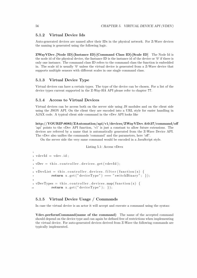
56 CHAPTER 5. VIRTUAL DEVICE API (VDEV)
5.1.2 Virtual Device Ids
Auto-generated devices are named after their IDs in the physical network. For Z-Wave devicesthe naming is generated using the following logic.
ZWayVDev [Node ID]:[Instance ID]:[Command Class ID]:[Scale ID] The Node Id isthe node id of the physical device, the Instance ID is the instance id of the device or ’0’ if there isonly one instance. The command class ID refers to the command class the function is embeddedin. The scale id is usually ’0’ unless the virtual device is generated from a Z-Wave device thatsupports multiple sensors with different scales in one single command class.
5.1.3 Virtual Device Type
Virtual devices can have a certain types. The type of the device can be chosen. For a list of thedevice types current supported in the Z-Way-HA API please refer to chapter ??.
5.1.4 Access to Virtual Devices
Virtual devices can be access both on the server side using JS modules and on the client sideusing the JSON API. On the client they are encoded into a URL style for easier handling inAJAX code. A typical client side command in the vDev API looks like
http://YOURIP:8083/ZAutomation/api/v1/devices/ZWayVDev 6:0:37/command/off’api’ points to the vDev API function, ’v1’ is just a constant to allow future extensions. Thedevices are referred by a name that is automatically generated from the Z-Wave Device API.The vDev also unifies the commands ’command’ and the parameters, here ’off’.
On the server side the very same command would be encoded in a JavaScript style.
Listing 5.1: Access vDevs
1
2 vdevId = vdev . id ;3
4 vDev = t h i s . c o n t r o l l e r . d e v i c e s . get ( vdevId ) ;5
6 vDevList = t h i s . c o n t r o l l e r . d e v i c e s . f i l t e r ( func t i on ( x ) {7 return x . get ( ” deviceType ” ) === ” switchBinary ” ; } ) ;8
9 vDevTypes = t h i s . c o n t r o l l e r . d e v i c e s . map( func t i on ( x ) {10 return x . get ( ” deviceType ” ) ; } ) ;
5.1.5 Virtual Device Usage / Commands
In case the virtual device is an actor it will accept and execute a command using the syntax:
Vdev.performCommand(name of the command) The name of the accepted commandshould depend on the device type and can again be defined free of restrictions when implementingthe virtual device. For auto-generated devices derived from Z-Wave the following commands aretypically implemented.
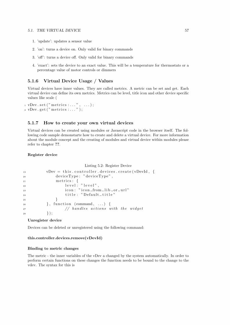
5.1. THE VIRTUAL DEVICE 57
1. ’update’: updates a sensor value
2. ’on’: turns a device on. Only valid for binary commands
3. ’off’: turns a device off. Only valid for binary commands
4. ’exact’: sets the device to an exact value. This will be a temperature for thermostats or apercentage value of motor controls or dimmers
5.1.6 Virtual Device Usage / Values
Virtual devices have inner values. They are called metrics. A metric can be set and get. Eachvirtual device can define its own metrics. Metrics can be level, title icon and other device specificvalues like scale (
1 vDev . s e t ( ” metr i c s : . . . ” , . . . ) ;2 vDev . get ( ” met r i c s : . . . ” ) ;
5.1.7 How to create your own virtual devices
Virtual devices can be created using modules or Javascript code in the browser itself. The fol-lowing code sample demonstarte how to create and delete a virtual device. For more informationabout the module concept and the creating of modules and virtual device within modules pleaserefer to chapter ??.
Register device
Listing 5.2: Register Device
19 vDev = t h i s . c o n t r o l l e r . d e v i c e s . c r e a t e ( vDevId , {20 deviceType : ” deviceType ” ,21 metr i c s : {22 l e v e l : ” l e v e l ” ,23 i con : ” i con from l i b or u r l ”24 t i t l e : ” Defau l t t i t l e ”25 }26 } , f unc t i on (command , . . . ) {27 // hand les a c t i on s wi th the widge t28 } ) ;
Unregister device
Devices can be deleted or unregistered using the following command:
this.controller.devices.remove(vDevId)
Binding to metric changes
The metric - the inner variables of the vDev a changed by the system automatically. In order toperform certain functions on these changes the function needs to be bound to the change to thevdev. The syntax for this is
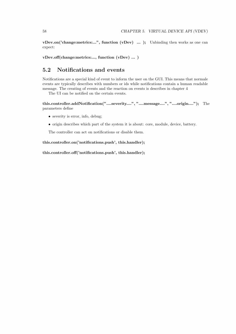
58 CHAPTER 5. VIRTUAL DEVICE API (VDEV)
vDev.on(’change:metrics:...”, function (vDev) ... ); Unbinding then works as one canexpect:
vDev.off(change:metrics:..., function (vDev) ... )
5.2 Notifications and events
Notifications are a special kind of event to inform the user on the GUI. This means that normaleevents are typically describes with numbers or ids while notifications contain a human readablemessage. The creating of events and the reaction on events is describes in chapter 4
The UI can be notified on the certain events.
this.controller.addNotification(”....severity....”, ”....message....”, ”....origin....”); Theparameters define
• severity is error, info, debug;
• origin describes which part of the system it is about: core, module, device, battery.
The controller can act on notifications or disable them.
this.controller.on(’notifications.push’, this.handler);
this.controller.off(’notifications.push’, this.handler);
Chapter 6
Z-Way Data Model Reference
6.1 zway
• Description: zway is the Z-Way part of the object tree
• Syntax: zway.X with X as child object
• Child objects
– controller: controller object, see below for details
– devices: devices list, see below for details
– version: Z-Way.JS version
– isRunning(): Check if Z-Way is running
– isIdle(): Check if Z-Way is idle (no pending packets to send)
– discover(): Start Z-Way discovery process
– stop() : Stop Z-Way
– InspectQueue() : Returns list of pending jobs in the queue.
∗ item: [timeout, flags, nodeId, description, progress, payload]
∗ flags: [send count, wait wakeup, wait security, done, wait ACK, got ACK, waitresponse, got response, wait callback, got callback]
– ProcessPendingCallbacks(): Process pending callbacks (result of setTimeout/setInter-val or functions called via HTTP JSON API)
– bind(function, bitmask): Bind function to be called on change of devices list/instanceslist/command classes list
– unbind(function) : Unbind function previously bind with bind()
– all function classes in 8 are also methods of this data object
6.2 controller
You can access the data elements of ”controller” in the demo user interface in menu ”for experts+ Controller Info”
59
60 CHAPTER 6. Z-WAY DATA MODEL REFERENCE
• Description: Controller object
• Syntax: controller.X with X as child object
• Child objects
– data: Data tree of the controller
∗ APIVersion: Version of the Serial API
∗ SDK: System development kit version of the Transceiver firmware
∗ SISPresent: flase if SUIS is available
∗ SUCNodeId: Node ID of SUC if present
∗ ZWVersion: ZWave Version (firmware)
∗ ZWaveChip: The name of the Z-Wave transceiver chip
∗ ZWlibMajor / ZWlibMinor: library version
∗ capabilities: array of function class ids
∗ controllerstate: flag to show inclusion mode etc
∗ countJobs: shall job be counted
∗ curSerialAPIAckTimeout10ms: timing parameter of serial interface
∗ curSerialAPIBytetimeout10ms: timing parameter of serial interface
∗ homeId:the home id of the controller
∗ isinOtherNetworks: flag to show if controller is real primary if in other network
∗ isPrimary: flag to show if controller is primary
∗ isRealprimary: flag to show if controller can be primary
∗ isSUC: is SUC present
∗ lastExcludedDevice: node ID of last excluded device
∗ lastIncludedDevice: node ID of last included device
∗ libType library basis type
∗ manufacturerIS / manufacturerProductId / manufacturerProductTypeId: ids toidentify the transceiver hardware
∗ memoryGetAddress
∗ memoryGetData
∗ nodeId: own node ID
∗ nonManagementJobs: number of non man. jobs
∗ oldSerialAPIAckTimeout10ms: default timing parameter of serial interface
∗ oldSerialAPIBytetimeout10ms: default timing parameter of serial interface
∗ softwareRevisonDate: written by compiler
∗ softwareRevisionID: written by compiler
∗ vendor: string of hardware vendor
– AddNodeToNetwork(mode): Reference to zway.AddNodeToNetwork()
– RemoveNodeFromNetwork(mode): Reference to zway.RemoveNodeFromNetwork()
– ControllerChange(mode): Reference to zway.ControllerChange()
– GetSUCNodeId(mode): Reference to zway.GetSUCNodeId()
– SetSUCNodeId(nodeId): Assign SUC role to a device
– SetSISNodeId(nodeId): Assign SIS role to a device
– DisableSUCNodeId(nodeId): Revoke SUC/SIS role from a device
– SendNodeInformation(nodeId): Reference to zway.SendNodeInformation()
6.3. DEVICES 61
6.3 Devices
The devices object contains the array of the device objects. Each device in the network - includingthe controller itself - has a device object in Z-Way.
• Description: list of devices
• Syntax: X with X as child object
• Child objects
m : Device object
– length: Length of the list
– SaveData(): Save Z-Way Z-Wave data for hot start on next run (in config/zddx/HOMEID-DevicesData.xml)
6.4 Device
The data object can be accesses in the demo UI in advanced mode of ”Configuration”
• Description: the device object
• Syntax: device[n].X with X as child object
• Child objects
– id: (node) Id of the device
– Data: Data tree of the device
∗ SDK: SDK used in the device
∗ ZDDXMLFile: file of the Devcie Description Record
∗ ZWLib: Z-Wave library used
∗ ZWProtocolMajor / ZWProtocolMinor: Z-Wave protocol version
∗ applicationMajor / ApplicationMinor: Application Version of devices firmware
∗ basicType: basic Z-Wave device class
∗ beam: wake up beam required
∗ countFailed: statistics of failed packets sent (from start of process)
∗ countSuccess: statistics of sucessful packets sent (from start of process)
∗ deviceTypeString:
∗ genericType: generic Z-Wave device class
∗ infoProtocolSpecific
∗ isAwake
∗ isListening
∗ isFailed
∗ isRouting
∗ isVirtual:
∗ keeAwake: flag is device need to be kept awake
∗ lastRecevied: timestamp of last packet received
62 CHAPTER 6. Z-WAY DATA MODEL REFERENCE
∗ lastSend: timestamp of last sent operation
∗ ManufacturerId / manufacturerProductID / manufacturerProductTypeId: idsused to identify the device
∗ neightbours: list of neighbour nodes
∗ nodeInfoFrame: nodeinformation frame in bytes
∗ option: flag if optional command classes are present
∗ queueLength: length of device specific send queue
∗ sensor1000: flag if device is FLIRS with 1000 ms wakeup
∗ sensor250: flag if device is FLIRS with 250 ms wakeup
∗ specificType: specific Z-Wave device class
– instances: Instances list of the device
– RequestNodeInformation(): Request NIF
– RequestNodeNeighbourUpdate(): Request routes update
– InterviewForce(): Purge all command classes and start interview based on device’sNIF
– RemoveFailedNode(): Remove this node as failed. Device should be marked as failedto remove it with this function.
– SendNoOperation(): Ping the device with empty packet
– LoadXMLFile(file): Load new Z-Wave Device Description XML file. See http://pepper1.net/zwavedb/
– GuestXML(): Return the list of all known Z-Wave Device Description XML files withmatch score. [score, file name, brand name, product name, photo]
– WakeupQueue(): Pretend the device is awake and try to send packets
6.5 Instances
Each device may have multiple instances (similar functions like switches, same type sensors, ...)If only one instance is present the id of this instance is 0. Command classes are located ininstances only-
• Description: list of instances
• Syntax: device[n].instance[m].X with X as child object
• Child objects
m : instance object
– length: Length of the list
– commandClasses: list of command classes of this instance. In case there is only oneinstance, this is equivalent to the list of command classes of the device. For detailssee below.
– Data: data object of instance
∗ dynamic: flag if instance is dynamic
∗ genericType: generic Z-Wave device class of instance
∗ specificType: specific Z-Wave device class of instance
6.6. DATA 63
6.5.1 CommandClass
This is the command class object. It contains public methods and public data elements that aredescribed in chapter 7
• Description: Command Class Implementation
• Syntax: device[n].instance[m].commandclass[id].X with X as child object
• Child objects
– id: Id of the Command Class of the instance of the device
– data: Data tree of the Command Class
∗ interviewCounter: number of attempts left until interview is terminate even if notsuccessful
∗ interviewDone: flag if interview of the command class is finished
∗ security: flag if command class is operated under special security mode
∗ version: version of the command class implemented
∗ supported: flag if CC is supported or only controlled
∗ commandclass data: Command Class specific data - see chapter 7 for details.
– name: Command Class name
– Method: Command Class method - see chapter 7 for details.
6.6 Data
This is the description of the data object.General note: Z-Way objects and it’s decendents are NOT simple JS objects, but native JS
objects, that does not allow object modification.
• name: Name of data tree element
• updated: Update time
• invalidated: Invalidate time
• valueOf(): Returns value of the object (can be omitted to get object value)
• invalidate(): Invalidate data value (mark is as not valid anymore)
• bind(function (type[, arg]) ..., [arg, [watchChildren=false]]): Bind function to a change ofdata tree element of its descendants
• unbind(function): Unbind function bind previously with bind()

64 CHAPTER 6. Z-WAY DATA MODEL REFERENCE
Chapter 7
Command Class Reference
Command Classes are groups of wireless commands that allow using certain functions of a Z-wavedevice. In Z-Way each Z-Wave device has a data holder entry for each command class supported.During the inclusion and interview of the device the command class structure is instantiated inthe data holder and filled with certain data. Command Class commands change values of thecorresponding data holder structure. The follow list shows the public commands of the commandclasses supported with their parameters and the data holder objects changed.
The subsequent list shows the most important data holder values but the full set of datavalues can always be accesses using the demo UI. In expert mode there is a list of commandclasses with a simplified User Interface plus a link that visualizes all data holder elements.
7.1 FirmwareUpdate (0x7A/122)
Command Class values in data holder:
• ’updateStatus’: indicated the status of the update process
Perform
Syntax: FirmwareUpdatePerform(manufacturerId, firmwareId, firmwareTarget, size,Data, successCallback = NULL, failureCallback = NULL)
Description: Starts a firmware Update process
Parameter manufacturerId: This must be the Manufacturer ID of the device as re-ported in Version CC, can be copied from there
Parameter firmwareTarget: A device can have multiple firmwares, Id=0 points to theZ-Wave firmware
Parameter length: the length of the data structure
Parameter data: the bin encoded firmware
Return: data holder ”type id” is updated with sub variables srcId,sensorState,sensorTime
65
66 CHAPTER 7. COMMAND CLASS REFERENCE
7.2 Alarm (0x71/113)
Hands binary alarm events from binary sensors by alarm type. The following alarm types aredefined:
• 0x01: Smoke
• 0x02: CO
• 0x03: CO2
• 0x04: Heat
• 0x05: Water
• 0x06: Access Control
• 0x07: Burglar
• 0x08: Power Management
• 0x09: System
• 0x0a: Emergency
• 0x0b: Clock
Syntax: AlarmGet(type, event, successCallback = NULL, failureCallback = NULL)
Description: Requests the status of a specific event of a specific alarm type
Parameter type: Alarm type
Parameter event: Event type
Syntax: AlarmSet(type, level, successCallback = NULL, failureCallback = NULL)
Description: Status the status of a specific alarm type
Parameter type: Alarm type
Parameter level: New status
7.3 Command Class Alarm Sensor (0x9c/156)
The Alarm Sensor Command Class can be used to realize Sensor Alarms.
Command Class values in data holder:
• ’type’: A field with the type id as index what holds the information about the alarm sensors
7.4. COMMAND CLASS ASSOCIATION (0X85/133) 67
Command Alarm Sensor Get
Syntax: Get(type = -1, successCallback = NULL, failureCallback = NULL)
Description: Requests the status of the alarm sensor of type ’type’
Parameter type: Alarm type to get. -1 means get all types
Parameter successCallback: Custom function to be called on function success. NULLif callback is not needed
Parameter failureCallback: Custom function to be called on function failure. NULLif callback is not needed
Return: data holder ”type id” is updated with sub variables srcId,sensorState,sensorTime
7.4 Command Class Association (0x85/133)
The association command class allows to manage the association groups and the nodeIDs in theassociation groups.
Command Class values in data holder:
• groups: number of association groups
• group number: array of association groups with the child values: max (max number ofnodes allowed) and nodes as array of nodes in the association group
Command Association Get
Syntax: Get(groupId = 0, successCallback = NULL, failureCallback = NULL)
Description: Send Association Get
Parameter groupId: Group Id (from 1 to 255), 0 requests all groups
Parameter successCallback: Custom function to be called on function success. NULLif callback is not needed
Parameter failureCallback: Custom function to be called on function failure. NULLif callback is not needed
Return: data holder value ”nodes” in association group object is updated
Command Association Set
Syntax: Set(groupId, includeNode, successCallback = NULL, failureCallback = NULL)
Description: Send Association Set (Add)
Parameter groupId: Group Id (from 1 to 255)
Parameter includeNode: Node to be added to the group
Parameter successCallback: Custom function to be called on function success. NULLif callback is not needed
Parameter failureCallback: Custom function to be called on function failure. NULLif callback is not needed
Return: data holder value ”nodes” in association group object is updated
68 CHAPTER 7. COMMAND CLASS REFERENCE
Command Association Remove
Syntax: Remove(groupId, excludeNode, successCallback = NULL, failureCallback =NULL)
Description: Send Association Remove
Parameter groupId: Group Id (from 1 to 255)
Parameter excludeNode: Node to be removed from the group
Parameter successCallback: Custom function to be called on function success. NULLif callback is not needed
Parameter failureCallback: Custom function to be called on function failure. NULLif callback is not needed
Return: data holder value ”nodes” in association group object is updated
7.5 Command Class Basic (0x20/32)
The Basic Command Class is the wild card command class. Almost all Z-Wave devices supportthis command class but they interpret the command class commands in different ways. AThermostat will handle a Basic Set Command in a different way than a Dimmer but bothaccept the Basic Set command and act.
Command Class values in data holder:
• level: generic switching level of the device controlled
Command Basic Get
Syntax: Get(successCallback = NULL, failureCallback = NULL)
Description: Send Basic Get
Parameter successCallback: Custom function to be called on function success. NULLif callback is not needed
Parameter failureCallback: Custom function to be called on function failure. NULLif callback is not needed
Return: data holder ”level” is updated
Command Basic Set
Syntax: Set(value, successCallback = NULL, failureCallback = NULL)
Description: Send Basic Set
Parameter value: Value
Parameter successCallback: Custom function to be called on function success. NULLif callback is not needed
Parameter failureCallback: Custom function to be called on function failure. NULLif callback is not needed
Return: data holder ”level” is updated

7.6. COMMAND CLASS BATTERY (0X80/128) 69
7.6 Command Class Battery (0x80/128)
The battery command class allows monitoring the battery charging level of a device.
Command Class values in data holder:
• last: last battery charging level (0100
• history: an array of charging levels and UNIX time stamps, can be used to predict nexttime to change battery
• lastChange: UNIX time stamp of last battery change (if recognized)
Command Battery Get
Syntax: Get(successCallback = NULL, failureCallback = NULL)
Description: Send Battery Get
Parameter successCallback: Custom function to be called on function success. NULLif callback is not needed
Parameter failureCallback: Custom function to be called on function failure. NULLif callback is not needed
Return: data holder ”last” is updated, in case ”last” has changed, ”history” or”lastChange” may be updates
7.7 CentralScene (0x5B/91)
Received Central Scene Commands. They are triggered by pushing a button on a controllersupporting the central Scene Commmand Class
Command Class values in data holder:
• ’keyAttribute’: 0x00 = Key pressed, 0x01 = Key released, 0x02 = Key held down
• ’currentScene’: indicates the current activated scene
7.8 ClimateControlSchedule (0x46/70)
The command class is obsolete but still partly implemented for legacy reasons. No values orcommand class functions are exposed.
7.9 Command Class Clock (0x81/129)
The clock Command Class allows to sync the internal clock for timer dependent application suchas thermostats with schedules.
70 CHAPTER 7. COMMAND CLASS REFERENCE
Command Class Clock Get
Syntax: Get(successCallback = NULL, failureCallback = NULL)
Description: Send Clock Get
Parameter successCallback: Custom function to be called on function success. NULLif callback is not needed
Parameter failureCallback: Custom function to be called on function failure. NULLif callback is not needed
Command Class Clock Set
Syntax: Set(successCallback = NULL, failureCallback = NULL)
Description: Send Clock Set
Parameter successCallback: Custom function to be called on function success. NULLif callback is not needed
Parameter failureCallback: Custom function to be called on function failure. NULLif callback is not needed
7.10 Command Class Configuration(0x70/112)
The configuration command class is used to set certian configuration valeus that change thebehavior of the device. Z-Wave requires that every device works out of the box with out furtherconfiguration. However different configuration value significantly enhance the value a device.
Configuration parameters are identified by a 8 bit parameter number and a value that can be1, 2 or even 4 byte long. Z-Wave does not provide any information about the configuration valuesby wireless commands. User have to look into the device manual to learn about configurationparameters. The Device Description Record, incoprotated by Z-Way gives information aboutvalid parameters and the meaning of the values to be set.
Command Class values in data holder:
: Parameter value with child values size (1,2,4 byte) and value
Command Configuration Get
Syntax: Get(parameter, successCallback = NULL, failureCallback = NULL)
Description: Send Configuration Get
Parameter parameter: Parameter number (from 1 to 255)
Parameter successCallback: Custom function to be called on function success. NULLif callback is not needed
Parameter failureCallback: Custom function to be called on function failure. NULLif callback is not needed
Return: data holder with parameter number is updated or created when no available
7.11. COMMAND CLASS DOORLOCK (0X62/98) 71
Command Configuration Set
Syntax: Set(parameter, value, size = 0, successCallback = NULL, failureCallback =NULL)
Description: Send Configuration Set
Parameter parameter: Parameter number (from 1 to 255)
Parameter value: Value to be sent (negative and positive values are accepted, butwill be stripped to size)
Parameter size: Size of the value (1, 2 or 4 bytes). Use 0 to guess from previouslyreported value if any. 0 means use size previously obtained Get
Parameter successCallback: Custom function to be called on function success. NULLif callback is not needed
Parameter failureCallback: Custom function to be called on function failure. NULLif callback is not needed
Return: data holder with parameter number is updated
Command Configuration SetDefault
Syntax: SetDefault(parameter, successCallback = NULL, failureCallback = NULL)
Description: Send Configuration SetDefault
Parameter parameter: Parameter number to be set to device default
Parameter successCallback: Custom function to be called on function success. NULLif callback is not needed
Parameter failureCallback: Custom function to be called on function failure. NULLif callback is not needed
7.11 Command Class DoorLock (0x62/98)
The door lock command class allows to operate an electronic door lockCommand Class values in data holder:
• mode: general operating mode of lock
• insideMode: for inside handle
• outsideMode: for outside handle
• lockMinutes: setup value fo timeout
• lockSeconds: setup value fo timeout
• condition:
72 CHAPTER 7. COMMAND CLASS REFERENCE
• insideState: state of inside handle
• outsideState: state of outside handle
• timeoutMinutes: time to timeout mode
• timeoutSeconds: time to timeout mode
• opType”));
Command Class DoorLock Get
Syntax: Get(successCallback = NULL, failureCallback = NULL)
Description: Send DoorLock Get
Parameter successCallback: Custom function to be called on function success. NULLif callback is not needed
Parameter failureCallback: Custom function to be called on function failure. NULLif callback is not needed
Command Class DoorLock ConfigurationGet
Syntax: ConfigurationGet(successCallback = NULL, failureCallback = NULL)
Description: Send DoorLock Configuration Get
Parameter successCallback: Custom function to be called on function success. NULLif callback is not needed
Parameter failureCallback: Custom function to be called on function failure. NULLif callback is not needed
Command Class DoorLock Set
Syntax: Set(mode, successCallback = NULL, failureCallback = NULL)
Description: Send DoorLock Configuration Set
Parameter mode: Lock mode
Parameter successCallback: Custom function to be called on function success. NULLif callback is not needed
Parameter failureCallback: Custom function to be called on function failure. NULLif callback is not needed
7.12. COMMAND CLASS DOOR LOCK LOGGING (0X4C/76) 73
Command Class DoorLock ConfigurationSet
Syntax: ConfigurationSet(opType, outsideState, insideState, lockMin, lockSec, suc-cessCallback = NULL, failureCallback = NULL)
Description: Send DoorLock Configuration Set
Parameter opType: Operation type
Parameter outsideState: State of outside door handle
Parameter insideState: State of inside door handle
Parameter lockMin: Lock after a specified time (minutes part)
Parameter lockSec: Lock after a specified time (seconds part)
Parameter successCallback: Custom function to be called on function success. NULLif callback is not needed
Parameter failureCallback: Custom function to be called on function failure. NULLif callback is not needed
7.12 Command Class Door Lock Logging (0x4C/76)
The Door Lock Logging Command Class allows to receive reports about all successful and failedactivities of the electronic door lock
Command Class values in data holder:
• log record: The data holder contains the log history
Command Door Lock Log LoggingGet
Syntax: LoggingGet(records,successCallback = NULL, failureCallback = NULL)
Description: Calls the log entries from the lock
Parameter records: max number of records
Parameter successCallback: Custom function to be called on function success. NULLif callback is not needed
Parameter failureCallback: Custom function to be called on function failure. NULLif callback is not needed
Return: data holder is updated
7.13 Command Class Indicator (0x87/135)
The indicator command class operates the indicator on the physical device if available. This canbe used to identify a device or use the indicator for special purposes.
Command Class values in data holder:
• stat: The status of the indicator
74 CHAPTER 7. COMMAND CLASS REFERENCE
Command Indicator Get
Syntax: Get(successCallback = NULL, failureCallback = NULL)
Description: Calls the indicator status from the device
Parameter successCallback: Custom function to be called on function success. NULLif callback is not needed
Parameter failureCallback: Custom function to be called on function failure. NULLif callback is not needed
Return: data holder stat is updated
Command Class Indicator Set
Syntax: Set(stat, successCallback = NULL, failureCallback = NULL)
Description: Send Indicator Set
Parameter stat: indicator status value
Parameter successCallback: Custom function to be called on function success. NULLif callback is not needed
Parameter failureCallback: Custom function to be called on function failure. NULLif callback is not needed
7.14 Command Class Meter (0x32/50)
The meter command class allows to read different kind of meters. Z-Wave differentiates differentmeter types and different meter scales. Please refer to the file /translations/scales.xml for detailsabout possible meter types and values.
Command Class values in data holder:
• resettable: flag to indicate of the meter can be reset
typeId : One meter device can have different meters. Each meter object has the following childobjects:
– delta: difference between last and actual meter value.
– previous: previous meter value (gotten with last GET request
– rateType: meter rate type
– scale: meter scale id
– scaleString: string representation of meter scale. Refer to /translations/scales.xml forscale types.
– sensorType: meter type id. Refer to /translations/scales.xml for types
– sensorTypeString: string representation of sensor Type. Refer to /translations/s-cales.xml for type strings
– val: The actual meter value
7.15. METERTABLEMONITOR (0X3D/61) 75
Command Meter Get
Syntax: Get(scale = -1, successCallback = NULL, failureCallback = NULL)
Description: Send Meter Get
Parameter scale: Desired scale. -1 for all scales
Parameter successCallback: Custom function to be called on function success. NULLif callback is not needed
Parameter failureCallback: Custom function to be called on function failure. NULLif callback is not needed
Return: data holder values of meter id are updated
Command Meter Reset
Syntax: Reset(successCallback = NULL, failureCallback = NULL)
Description: Send Meter Reset
Parameter successCallback: Custom function to be called on function success. NULLif callback is not needed
Parameter failureCallback: Custom function to be called on function failure. NULLif callback is not needed
7.15 MeterTableMonitor (0x3D/61)
The Meter Table Monitor Command Class defines the Commands necessary to read historicaland accumulated values in physical units from a water meter or other metering device (gas,electric etc.) and thereby enabling automatic meter reading capabilities
MeterTableMonitorGetAdminId
Syntax: MeterTableMonitorGetAdminId(successCallback = NULL, failureCallback= NULL)
Description: The Meter Table Point Adm. Number Get Command is used to requestthe Meter Point Administration Number to identify customer.
MeterTableMonitorGetId
Syntax: MeterTableMonitorGetId(successCallback = NULL, failureCallback = NULL)
Description: The Meter Table ID Get Command is used to request the parametersused for identification of customer and metering device.
76 CHAPTER 7. COMMAND CLASS REFERENCE
MeterTableMonitorStatusDepthGet
Syntax: MeterTableMonitorStatusDepthGet(depth, successCallback = NULL, fail-ureCallback = NULL)
Description: The Meter Table Status Date Get Command is used to request a numberof status events recorded in a certain time interval. If the meter does not support astatus event log history it must return the current state of the meter
MeterTableMonitorCurrentDataGet
Syntax: MeterTableMonitorStatusDateGet(maxResults, startDate, endDate, , suc-cessCallback = NULL, failureCallback = NULL)
Description: The Meter Table Current Data Get Command is used to request anumber of time stamped values (current) in physical units according to the datasetmask.
MeterTableMonitorCurrentDataGet
Syntax: MeterTableMonitorCurrentDataGet(setId, successCallback = NULL, fail-ureCallback = NULL)
Description:
MeterTableMonitorHistoricalDataGet
Syntax: MeterTableMonitorHistoricalDataGet(setId, maxResults, startDate, end-Date, successCallback = NULL, failureCallback = NULL)
Description: The Meter Table Historical Data Get Command is used to request anumber of time stamped values (historical) in physical units according to rate type,dataset mask and time interval.
7.16 Command Class Multichannel Association (0x8e/142)
This is an enhancement to the Association Command Class. The command class follows thesame logic as the Association command class and has the same commands but accepts differentinstance values.
Command MultiChannelAssociation Get
Syntax: Get(groupId = 0, successCallback = NULL, failureCallback = NULL)
Description: Send MultiChannelAssociation Get
Parameter groupId: Group Id (from 1 to 255), 0 requests all groups
Parameter successCallback: Custom function to be called on function success. NULLif callback is not needed
Parameter failureCallback: Custom function to be called on function failure. NULLif callback is not needed
7.17. COMMAND CLASS NODENAMING (0X77/119) 77
Command MultiChannelAssociation Set
Syntax: Set(groupId, includeNode, includeInstance, successCallback = NULL, fail-ureCallback = NULL)
Description: Send MultiChannelAssociation Set (Add)
Parameter groupId: Group Id (from 1 to 255)
Parameter includeNode: Node to be added to the group
Parameter includeInstance: Instance of the node to be added to the group
Parameter successCallback: Custom function to be called on function success. NULLif callback is not needed
Parameter failureCallback: Custom function to be called on function failure. NULLif callback is not needed
Command MultiChannelAssociation Remove
Syntax: Remove(groupId, excludeNode, excludeInstance, successCallback = NULL,failureCallback = NULL)
Description: Send MultiChannelAssociation Remove
Parameter groupId: Group Id (from 1 to 255)
Parameter excludeNode: Node to be removed from the group
Parameter excludeInstance: Instance of the node to be removed from the group
Parameter successCallback: Custom function to be called on function success. NULLif callback is not needed
Parameter failureCallback: Custom function to be called on function failure. NULLif callback is not needed
7.17 Command Class NodeNaming (0x77/119)
The Node naming command class allows assigning a readable string for a name and a locationto a physical device. The two strings are stored inside the device and can be called on request.There are no restrictions to the name except the maximum length of the string of 16 characters.
Command Class values in data holder:
• nodename: The name of the device
• location: the location of the device
• myname: The name of the Z-Way instance
• mylocation: the location of the Z-Way instance
78 CHAPTER 7. COMMAND CLASS REFERENCE
Command NodeNaming Get
Syntax: Get(successCallback = NULL, failureCallback = NULL)
Description: Send NodeNaming GetName and GetLocation
Parameter successCallback: Custom function to be called on function success. NULLif callback is not needed
Parameter failureCallback: Custom function to be called on function failure. NULLif callback is not needed
Return: data holder ”nodename” and ”location” are updated
Command NodeNaming GetName
Syntax: GetName(successCallback = NULL, failureCallback = NULL)
Description: Send NodeNaming GetName
Parameter successCallback: Custom function to be called on function success. NULLif callback is not needed
Parameter failureCallback: Custom function to be called on function failure. NULLif callback is not needed
Return: data holder ”nodename” is updated
Command NodeNaming GetLocation
Syntax: GetLocation(successCallback = NULL, failureCallback = NULL)
Description: Send NodeNaming GetLocation
Parameter successCallback: Custom function to be called on function success. NULLif callback is not needed
Parameter failureCallback: Custom function to be called on function failure. NULLif callback is not needed
Return: data holder ”location” is updated
Command NodeNaming SetName
Syntax: SetName(name, successCallback = NULL, failureCallback = NULL)
Description: Send NodeNaming SetName
Parameter name: Value
Parameter successCallback: Custom function to be called on function success. NULLif callback is not needed
Parameter failureCallback: Custom function to be called on function failure. NULLif callback is not needed
Return: data holder ”nodename” is updated
7.18. POWERLEVEL (0X73/115) 79
Command NodeNaming SetLocation
Syntax: SetLocation(location, successCallback = NULL, failureCallback = NULL)
Description: Send NodeNaming SetLocation
Parameter location: Value
Parameter successCallback: Custom function to be called on function success. NULLif callback is not needed
Parameter failureCallback: Custom function to be called on function failure. NULLif callback is not needed
Return: data holder ”location” is updated
7.18 PowerLevel (0x73/115)
This Command Class ist used to test the link budget to a given other device identified by itsnode ID. The command class will vary the transmit level and send a number of test frames andcounts those successfully transmitted.
Command Class values in data holder:
• ’status’: status of power test
• ’acknowledgedFrames’: ’good’ frames
• ’totalFrames’: total frames sent
PowerLevelGet
Syntax: PowerLevelGet(successCallback = NULL, failureCallback = NULL)
Description: returns the actual (TX) power level of te node
PowerLevelSet
Syntax: PowerLevelSet(level,timeout, successCallback = NULL, failureCallback =NULL)
Description: The Powerlevel Set Command used to set the power level indicatorvalue, which SHOULD be used by the node when transmitting RF, and the timeoutfor this power level indicator value before returning the power level defined by theapplication.
Parameter level: power level
Parameter timeout: timeout in sec
80 CHAPTER 7. COMMAND CLASS REFERENCE
PowerLevelTestNodeSet
Syntax: PowerLevelTestNodeSet(testNodeId, level, frameCount, successCallback =NULL, failureCallback = NULL)
Description: instruct the testNode to send out ’framecount’ number of frames with(TX) power level ’level’
Parameter testNodeId: Node ID if the link to be tested
Parameter level: power level used
Parameter framecount: number of frames used for testing
PowerLevelTestNodeGet
Syntax: PowerLevelTestNodeGet(successCallback = NULL, failureCallback = NULL)
Description: requests the result of the latest powerlevel test started with PowerLevel-TestNodeSet
7.19 Command Class Protection (0x75/117)
This command class is used to disable local control of the device.
Command Class Protection Get
Syntax: Get(successCallback = NULL, failureCallback = NULL)
Description: Send Protection Get
Parameter successCallback: Custom function to be called on function success. NULLif callback is not needed
Parameter failureCallback: Custom function to be called on function failure. NULLif callback is not needed
Command Class Protection Set
Syntax: Set(state, rfState = 0, successCallback = NULL, failureCallback = NULL)
Description: Send Protection Set
Parameter state: Local control protection state
Parameter rfState: RF control protection state
Parameter successCallback: Custom function to be called on function success. NULLif callback is not needed
Parameter failureCallback: Custom function to be called on function failure. NULLif callback is not needed
7.19. COMMAND CLASS PROTECTION (0X75/117) 81
Command Class Protection ExclusiveGet
Syntax: ExclusiveGet(successCallback = NULL, failureCallback = NULL)
Description: Send Protection Exclusive Control Get
Parameter successCallback: Custom function to be called on function success. NULLif callback is not needed
Parameter failureCallback: Custom function to be called on function failure. NULLif callback is not needed
Command Class Protection ExclusiveSet
Syntax: ExclusiveSet(controlNodeId, successCallback = NULL, failureCallback =NULL)
Description: Send Protection Exclusive Control Set
Parameter controlNodeId: Node Id to have exclusive control over destination node
Parameter successCallback: Custom function to be called on function success. NULLif callback is not needed
Parameter failureCallback: Custom function to be called on function failure. NULLif callback is not needed
Command Class Protection TimeoutGet
Syntax: TimeoutGet(successCallback = NULL, failureCallback = NULL)
Description: Send Protection Timeout Get
Parameter successCallback: Custom function to be called on function success. NULLif callback is not needed
Parameter failureCallback: Custom function to be called on function failure. NULLif callback is not needed
Command Class Protection TimeoutSet
Syntax: TimeoutSet(timeout, successCallback = NULL, failureCallback = NULL)
Description: Send Protection Timeout Set
Parameter timeout: Timeout in seconds. 0 is no timer set. -1 is infinite timeout.max value is 191 minute (11460 seconds). values above 1 minute are ...
Parameter successCallback: Custom function to be called on function success. NULLif callback is not needed
Parameter failureCallback: Custom function to be called on function failure. NULLif callback is not needed
82 CHAPTER 7. COMMAND CLASS REFERENCE
7.20 Command Class SceneActivation(0x2B/43)
Command Class SceneActivation Set
Syntax: Set(sceneId, dimmingDuration = 0xff, successCallback = NULL, failureCall-back = NULL)
Description: Send SceneActivation Set
Parameter sceneId: Scene Id
Parameter dimmingDuration: Dimming duration
Parameter successCallback: Custom function to be called on function success. NULLif callback is not needed
Parameter failureCallback: Custom function to be called on function failure. NULLif callback is not needed
7.21 Command Class SceneControllerConf (0x2d/45)
Command Class SceneControllerConf
Syntax: Get(group = 0, successCallback = NULL, failureCallback = NULL)
Description: Send SceneControllerConf Get
Parameter group: Group Id
Parameter successCallback: Custom function to be called on function success. NULLif callback is not needed
Parameter failureCallback: Custom function to be called on function failure. NULLif callback is not needed
Command Class SceneControllerConf Set
Syntax: Set(group, scene, duration = 0x0, successCallback = NULL, failureCallback= NULL)
Description: Send SceneControllerConf Set
Parameter group: Group Id
Parameter scene: Scene Id
Parameter duration: Duration
Parameter successCallback: Custom function to be called on function success. NULLif callback is not needed
Parameter failureCallback: Custom function to be called on function failure. NULLif callback is not needed
7.22. COMMAND CLASS SCENEACTUATORCONF (0X2C/44) 83
7.22 Command Class SceneActuatorConf (0x2C/44)
Command Class values in data holder:
• currentScene: the actual scene
Command Class SceneActuatorConf Get
Syntax: Get(scene = 0, successCallback = NULL, failureCallback = NULL)
Description: Send SceneActuatorConf Get
Parameter scene: Scene Id
Parameter successCallback: Custom function to be called on function success. NULLif callback is not needed
Parameter failureCallback: Custom function to be called on function failure. NULLif callback is not needed
Command Class SceneActuatorConf Set
Syntax: Set(scene, level, dimming = 0xff, override = TRUE, successCallback =NULL, failureCallback = NULL)
Description: Send SceneActuatorConf Set
Parameter scene: Scene Id
Parameter level: Level
Parameter dimming: Dimming
Parameter override: If false then the current settings in the device is associated withthe Scene Id. If true then the Level value is used
Parameter successCallback: Custom function to be called on function success. NULLif callback is not needed
Parameter failureCallback: Custom function to be called on function failure. NULLif callback is not needed
7.23 Schedule (0x53/83)
The Schedule Command Class allows devices to exchange schedules which specify when to set anew behaviour. The Schedule Command Class is a generic scheduling command class that canbe used to make schedules for any device type.
ScheduleGet Tequest the current schedule in a device for a specific schedule ID
Syntax: ScheduleGet(slotId, successCallback = NULL, failureCallback = NULL)
Parameter slotId: the storage slot of the schedule
84 CHAPTER 7. COMMAND CLASS REFERENCE
7.24 Command Class ScheduleEntryLock (0x4e/78)
Controls access to a door lock based on times and intervals
Command Class ScheduleEntryLock Enable
Syntax: Enable(user, enable, successCallback = NULL, failureCallback = NULL)
Description: Send ScheduleEntryLock Enable(All)
Parameter user: User to enable/disable schedule for. 0 to enable/disable for all users
Parameter enable: TRUE to enable schedule, FALSE otherwise
Parameter successCallback: Custom function to be called on function success. NULLif callback is not needed
Parameter failureCallback: Custom function to be called on function failure. NULLif callback is not needed
Command Class ScheduleEntryLock WeekdayGet
Syntax: WeekdayGet(user, slot, successCallback = NULL, failureCallback = NULL)
Description: Send ScheduleEntryLock Weekday Get
Parameter user: User to get schedule for. 0 to get for all users
Parameter slot: Slot to get schedule for. 0 to get for all slots
Parameter successCallback: Custom function to be called on function success. NULLif callback is not needed
Parameter failureCallback: Custom function to be called on function failure. NULLif callback is not needed
Command Class ScheduleEntryLock WeekdaySet
Syntax: WeekdaySet(user, slot, dayOfWeek, startHour, startMinute, stopHour, stop-Minute, successCallback = NULL, failureCallback = NULL)
Description: Send ScheduleEntryLock Weekday Set
Parameter user: User to set schedule for
Parameter slot: Slot to set schedule for
Parameter dayOfWeek: Weekday number (0..6). 0 = Sunday. . 6 = Saturday
Parameter startHour: Hour when schedule starts (0..23)
Parameter startMinute: Minute when schedule starts (0..59)
Parameter stopHour: Hour when schedule stops (0..23)
Parameter stopMinute: Minute when schedule stops (0..59)
Parameter successCallback: Custom function to be called on function success. NULLif callback is not needed
Parameter failureCallback: Custom function to be called on function failure. NULLif callback is not needed
7.24. COMMAND CLASS SCHEDULEENTRYLOCK (0X4E/78) 85
Command Class ScheduleEntryLock YearGet
Syntax: YearGet(user, slot, successCallback = NULL, failureCallback = NULL)
Description: Send ScheduleEntryLock Year Get
Parameter user: User to enable/disable schedule for. 0 to get for all users
Parameter slot: Slot to get schedule for. 0 to get for all slots
Parameter successCallback: Custom function to be called on function success. NULLif callback is not needed
Parameter failureCallback: Custom function to be called on function failure. NULLif callback is not needed
Command Class ScheduleEntryLock YearSet
Syntax: YearSet(user, slot, startYear, startMonth, startDay, startHour, startMinute,stopYear, stopMonth, stopDay, stopHour, stopMinute, successCallba
Description: Send ScheduleEntryLock Year Set
Parameter user: User to set schedule for
Parameter slot: Slot to set schedule for
Parameter startYear: Year in current century when schedule starts (0..99)
Parameter startMonth: Month when schedule starts (1..12)
Parameter startDay: Day when schedule starts (1..31)
Parameter startHour: Hour when schedule starts (0..23)
Parameter startMinute: Minute when schedule starts (0..59)
Parameter stopYear: Year in current century when schedule stops (0..99)
Parameter stopMonth: Month when schedule stops (1..12)
Parameter stopDay: Day when schedule stops (1..31)
Parameter stopHour: Hour when schedule stops (0..23)
Parameter stopMinute: Minute when schedule stops (0..59)
Parameter successCallback: Custom function to be called on function success. NULLif callback is not needed
Parameter failureCallback: Custom function to be called on function failure. NULLif callback is not needed
86 CHAPTER 7. COMMAND CLASS REFERENCE
7.25 Command Class SensorBinary (0x30/48)
Command Class values in data holder:
• level: level of the binary sensor
Command SensorBinary Get
Syntax: Get(sensorType = 0, successCallback = NULL, failureCallback = NULL)
Description: Send SensorBinary Get
Parameter successCallback: Custom function to be called on function success. NULLif callback is not needed
Parameter sensorType: Type of sensor to query information for. 0xFF to queryinformation for the first available sensor type
Parameter failureCallback: Custom function to be called on function failure. NULLif callback is not needed
Return: data holder value ”level” is updated
7.26 Command Class Sensor Configuration (0x9e/158)
Allows to set a certain trigger level for a sensor to trigger
Command Class SensorConfiguration Get
Syntax: Get(successCallback = NULL, failureCallback = NULL)
Description: Send SensorConfiguration Get
Parameter successCallback: Custom function to be called on function success. NULLif callback is not needed
Parameter failureCallback: Custom function to be called on function failure. NULLif callback is not needed
Command Class SensorConfiguration Set
Syntax: Set(mode, value, successCallback = NULL, failureCallback = NULL)
Description: Send SensorConfiguration Set
Parameter mode: Value set mode
Parameter value: Value
Parameter successCallback: Custom function to be called on function success. NULLif callback is not needed
Parameter failureCallback: Custom function to be called on function failure. NULLif callback is not needed
7.27. COMMAND CLASS SENSOR MULTILEVEL (0X31/49) 87
7.27 Command Class Sensor Multilevel (0x31/49)
The sensor multilevel command class allows to read different kind of sensor. Z-Wave differentiatesdifferent sensor types and different scales of this sensor. Please refer to the file /translations/s-cales.xml for details about possible sensor types and values.
Command Class values in data holder:
typeId : One sensor device can have different sensor. Each sensor object has the following childobjects:
– scale: sensor scale id
– scaleString: string representation of sensor scale. Refer to /translations/scales.xmlfor scale types.
– sensorType: sensor type id. Refer to /translations/scales.xml for types
– sensorTypeString: string representation of sensor Type. Refer to /translations/s-cales.xml for type strings
– val: The actual sensor value
Command SensorMultilevel Get
Syntax: Get(sensorType = -1, successCallback = NULL, failureCallback = NULL)
Description: Send SensorMultilevel Get
Parameter sensorType: Type of sensor to be requested. -1 means all sensor typessupported by the device
Parameter successCallback: Custom function to be called on function success. NULLif callback is not needed
Parameter failureCallback: Custom function to be called on function failure. NULLif callback is not needed
Return: data holder values of sensorIds are updated
7.28 Command Class Switch All (0x27/39)
This command class controls the behavior of a actuator on Switch all commands. It can accept,both on and off, only on, only off or nothing.
Command Class values in data holder:
• mode: the current acceptance mode
Command SwitchAll Get
Syntax: Get(successCallback = NULL, failureCallback = NULL)
Description: Send SwitchAll Get
Parameter successCallback: Custom function to be called on function success. NULLif callback is not needed
Parameter failureCallback: Custom function to be called on function failure. NULLif callback is not needed
Return: data holder for ”mode” is updated
88 CHAPTER 7. COMMAND CLASS REFERENCE
Command SwitchAll Set
Syntax: Set(mode, successCallback = NULL, failureCallback = NULL)
Description: Send SwitchAll Set
Parameter mode: SwitchAll Mode: see definitions below
Parameter successCallback: Custom function to be called on function success. NULLif callback is not needed
Parameter failureCallback: Custom function to be called on function failure. NULLif callback is not needed
Return: data holder for ”mode” is updated
Command SwitchAll SetOn
Syntax: SetOn(successCallback = NULL, failureCallback = NULL)
Description: Send SwitchAll Set On
Parameter successCallback: Custom function to be called on function success. NULLif callback is not needed
Parameter failureCallback: Custom function to be called on function failure. NULLif callback is not needed
Command SwitchAll SetOff
Syntax: SetOff(successCallback = NULL, failureCallback = NULL)
Description: Send SwitchAll Set Off
Parameter successCallback: Custom function to be called on function success. NULLif callback is not needed
Parameter failureCallback: Custom function to be called on function failure. NULLif callback is not needed
7.29 Command Class SwitchColor (0x33/51)
Allows to define color for multicolor LED lights. It based on capabilities:
• 0: Warm White (0x00 0xFF: 0 100%)
• 1: Cold White (0x00: - 0xFF: 0 100%)
• 2: Red (0x00 0xFF: 0 100%)
• 3: Green (0x00 0xFF: 0 100%)
• 4: Blue (0x00 0xFF: 0 100%)
7.29. COMMAND CLASS SWITCHCOLOR (0X33/51) 89
• 5: Amber (for 6ch Color mixing) (0x00 0xFF: 0 100%)
• 6: Cyan (for 6ch Color mixing) (0x00 0xFF: 0 100%)
• 7: Purple (for 6ch Color mixing) (0x00 0xFF: 0 100%)
• 8: Indexed Color (0x00 0x0FF: Color Index 0-255)
Command Class values in data holder:
capability Id : A data holder for available capability. it contains the status level
Command SwitchColor Get
Syntax: Get(capabilityId, successCallback=NULL, failureCallback=NULL)
Description: Requests a status of the a certain capability
Parameter capability: the id of the capability
Return: data holder ’capability Id’ is updated with status
Command SwitchColor Set
Syntax: Set(capabilityId, value, duration=0xff, successCallback=NULL, failureCall-back=NULL)
Description: sets the status of a capability
Parameter capability: the id of the capability
Parameter value: new desired value of this capability
Parameter duration: time to change capability state
Duration argument is only valid for SwitchColor CC version 2 (it is ignored for version 1). Itmay have the following values:
0 : Change value instantly
1-127 : Duration between 1 and 127 seconds
128-254 : Duration between 1 and 127 minutes
255 : Factory default (device-specific)
Command SwitchColor SetMultiple
Syntax: SetMultiple(count, [capabilityIds], [states], duration=0xff, successCallback=NULL,failureCallback=NULL )
Description: sets the status of a multiple capabilities
Parameter count: number of array members
Parameter capabilities: array of ids of the capability
Parameter state: array of new desired states of this capabilities
Parameter duration: time to change capability state
90 CHAPTER 7. COMMAND CLASS REFERENCE
Command SwitchColor StartLevelChange
Syntax: StartLevelChange(capabilityId, dir, successCallback=NULL, failureCallback=NULL)
Description: Start the change of a capability status
Parameter capability: the id of the capability
Others Parameters: see SwitchMultilevel Parameters
Command SwitchColor StopStateChange
Syntax: StopStateChange(capabilityId, ZJobCustomCallback successCallback, suc-cessCallback=NULL, failureCallback=NULL)
Description: stop change of capability status
Parameter capability: the id of the capability
Return: data holder ’capability Id’ is updated with status
7.30 Command Class SwitchBinary(0x25/37)
The Switch Binary Command Class is used to control all actuators with simple binary (on/off)switching functions, primarily electrical switches.
Command Class values in data holder:
• Level: the level of the remotely controlled device
• mylevel: the level of the switch multilevel emulation of Z-Way
Command SwitchBinary Get
Syntax: Get(successCallback = NULL, failureCallback = NULL)
Description: Send SwitchBinary Get
Parameter successCallback: Custom function to be called on function success. NULLif callback is not needed
Parameter failureCallback: Custom function to be called on function failure. NULLif callback is not needed
Return: data holder ”level” is updated
Command SwitchBinary Set
Syntax: Set(value, successCallback = NULL, failureCallback = NULL)
Description: Send SwitchBinary Set
Parameter value: Value
Parameter successCallback: Custom function to be called on function success. NULLif callback is not needed
Parameter failureCallback: Custom function to be called on function failure. NULLif callback is not needed
Return: data holder ”level” is updated
7.31. COMMAND CLASS SWITCHMULTILEVEL (0X26/38) 91
7.31 Command Class SwitchMultilevel (0x26/38)
The Switch Multilevel Command Class is used to control all actuators with multilevel switchingfunctions, primarily Dimmers and Motor Controlling devices.
Command Class values in data holder:
• Level: the level of the remotely controlled device
• mylevel: the level of the switch multilevel emulation of Z-Way
Command SwitchMultilevel Get
Syntax: Get(successCallback = NULL, failureCallback = NULL)
Description: Send SwitchMultilevel Get
Parameter successCallback: Custom function to be called on function success. NULLif callback is not needed
Parameter failureCallback: Custom function to be called on function failure. NULLif callback is not needed
Return: data holder ”level” is updated
Command SwitchMultilevel Set
Syntax: Set(level, duration = 0xff, successCallback = NULL, failureCallback =NULL)
Description: Send SwitchMultilevel Set
Parameter level: Level to be set
Parameter duration: Duration of change:. 0 instantly. 1-127 in seconds. 128-254 inminutes mapped to 1-127 (value 128 is 1 minute). 255 use device factory default
Parameter successCallback: Custom function to be called on function success. NULLif callback is not needed
Parameter failureCallback: Custom function to be called on function failure. NULLif callback is not needed
Return: data holder ”level” is updated
Command Class SwitchMultilevel StartLevelChange
Syntax: StartLevelChange(dir, duration = 0xff, ignoreStartLevel = TRUE, startLevel= 50, indec = 0, step = 0xff, successCallback = NULL, failureCallback = NULL)
Description: Send SwitchMultilevel StartLevelChange
Parameter dir: Direction of change: 0 to incrase, 1 to decrase
92 CHAPTER 7. COMMAND CLASS REFERENCE
Parameter duration: Duration of change:. 0 instantly. 0x01-0x7f in seconds. 0x80-0xfe in minutes mapped to 1-127 (value 0x80=128 is 1 minute). 0xff us
Parameter ignoreStartLevel: If set to True, device will ignore start level value andwill use it’s curent value
Parameter startLevel: Start level to change from
Parameter indec: Increment/decrement type for step
Parameter step: Step to be used in level change in percentage. 0-99 mapped to1-100%. 0xff uses device factory default
Parameter successCallback: Custom function to be called on function success. NULLif callback is not needed
Parameter failureCallback: Custom function to be called on function failure. NULLif callback is not needed
Return: data holder ”level” is updated
Command SwitchMultilevel StopLevelChange
Syntax: StopLevelChange(successCallback = NULL, failureCallback = NULL)
Description: Send SwitchMultilevel StopLevelChange
Parameter successCallback: Custom function to be called on function success. NULLif callback is not needed
Parameter failureCallback: Custom function to be called on function failure. NULLif callback is not needed
Return: data holder ”level” is updated
7.32 Command Class ThermostatFanMode(0x44/68)
Allows to control the Thermostat FanCommand Class values in data holder:
• mode: fan mode
Command ThermostatFanMode Get
Syntax: Get(successCallback = NULL, failureCallback = NULL)
Description: Send ThermostatFanMode Get
Parameter successCallback: Custom function to be called on function success. NULLif callback is not needed
Parameter failureCallback: Custom function to be called on function failure. NULLif callback is not needed
Return: data holder ”mode” is updated
7.33. COMMAND CLASS THERMOSTATFANSTATE(0X45/69) 93
Command ThermostatFanMode Set
Syntax: Set(mode, successCallback = NULL, failureCallback = NULL)
Description: Send ThermostatFanMode Set
Parameter mode: new fan mode
Parameter successCallback: Custom function to be called on function success. NULLif callback is not needed
Parameter failureCallback: Custom function to be called on function failure. NULLif callback is not needed
Return: data holder ”mode” is updated
7.33 Command Class ThermostatFanState(0x45/69)
Allows to control the Thermostat FanCommand Class values in data holder:
• state: fan state
Command ThermostatFanState Get
Syntax: Get(successCallback = NULL, failureCallback = NULL)
Description: Send ThermostatFanState Get
Parameter successCallback: Custom function to be called on function success. NULLif callback is not needed
Parameter failureCallback: Custom function to be called on function failure. NULLif callback is not needed
Return: data holder ”state” is updated
7.34 Command Class ThermostatMode (0x40/64)
This command class allows to switch a heating/cooling actuator in different modes. Duringinterview the mode mask is requested and the dat objects are create accordingly.
Command Class values in data holder:
• modemask: contains the modemask with bit to identify the different modes of the thermo-stat
• mode: the actual mode
modeID : list of all allowed modes with string representation.
94 CHAPTER 7. COMMAND CLASS REFERENCE
Command ThermostatMode Get
Syntax: Get(successCallback = NULL, failureCallback = NULL)
Description: Send ThermostatMode Get
Parameter successCallback: Custom function to be called on function success. NULLif callback is not needed
Parameter failureCallback: Custom function to be called on function failure. NULLif callback is not needed
Command ThermostatMode Set
Syntax: Set(mode, successCallback = NULL, failureCallback = NULL)
Description: Send ThermostatMode Set
Parameter mode: Thermostat Mode
Parameter successCallback: Custom function to be called on function success. NULLif callback is not needed
Parameter failureCallback: Custom function to be called on function failure. NULLif callback is not needed
7.35 Command Class ThermostatOperatingState (0x42/66)
This command class allows to determine the operating state of the thermostatCommand Class values in data holder:
• state: operating state
Command ThermostatOperatingState LoggingGet
Syntax:LoggingGet(successCallback = NULL, failureCallback = NULL)
Description: Send ThermostatOperatingState LoggingGet
Parameter successCallback: Custom function to be called on function success. NULLif callback is not needed
Parameter failureCallback: Custom function to be called on function failure. NULLif callback is not needed
7.36 Command Class ThermostatSetPoint (0x43/67)
This command class allows to set a certain setpoint to a thermostat. The command class can beapplied to different kind of thermostats (heating, cooling, ...), hence it has various modes.
Command Class values in data holder:
7.36. COMMAND CLASS THERMOSTATSETPOINT (0X43/67) 95
• modemask: contains the modemask with bit to identify the different modes of the thermo-stat
modeID : data object for each mode with the following child objects
– modeName: contains the modemask with bit to identify the different modes of thethermostat
– precision: data object for each mode with the following child objects
– scale: scale id of the thermostat value
– scaleString: string representation of the scale id
– setVal
– size: size of setpoint value in bte
– val
Command ThermostatSetPoint Get
Syntax: Get(mode = -1, successCallback = NULL, failureCallback = NULL)
Description: Send ThermostatSetPoint Get
Parameter mode: Thermostat Mode, -1 requests for all modes
Parameter successCallback: Custom function to be called on function success. NULLif callback is not needed
Parameter failureCallback: Custom function to be called on function failure. NULLif callback is not needed
Return: data holder for ”mode” is updated
Command ThermostatSetPoint Set
Syntax: Set(mode, value, successCallback = NULL, failureCallback = NULL)
Description: Send ThermostatSetPoint Set
Parameter mode: Thermostat Mode
Parameter value: temperature
Parameter successCallback: Custom function to be called on function success. NULLif callback is not needed
Parameter failureCallback: Custom function to be called on function failure. NULLif callback is not needed
Return: data holder for ”mode” is updated
96 CHAPTER 7. COMMAND CLASS REFERENCE
7.37 Command Class UserCode (0x63/99)
Command Class UserCode Get
Syntax: Get(user = -1, successCallback = NULL, failureCallback = NULL)
Description: Send UserCode Get
Parameter user: User index to get code for (1 ... maxUsers). -1 to get codes for allusers
Parameter successCallback: Custom function to be called on function success. NULLif callback is not needed
Parameter failureCallback: Custom function to be called on function failure. NULLif callback is not needed
Command Class UserCode Set
Syntax: Set(user, code, status = 0, successCallback = NULL, failureCallback =NULL)
Description: Send UserCode Set
Parameter user: User index to set code for (1...maxUsers) 0 means set for all users
Parameter code: Code to set (4...10 characters long)
Parameter status: Code status to set
Parameter successCallback: Custom function to be called on function success. NULLif callback is not needed
Parameter failureCallback: Custom function to be called on function failure. NULLif callback is not needed
7.38 Command Class Time (0x8a/138)
Command Class Time TimeGet
Syntax: TimeGet(successCallback = NULL, failureCallback = NULL)
Description: Send Time TimeGet
Parameter successCallback: Custom function to be called on function success. NULLif callback is not needed
Parameter failureCallback: Custom function to be called on function failure. NULLif callback is not needed

7.39. COMMAND CLASS TIMEPARAMETERS (0X8B/139) 97
Command Class Time DateGet
Syntax: DateGet(successCallback = NULL, failureCallback = NULL)
Description: Send Time DateGet
Parameter successCallback: Custom function to be called on function success. NULLif callback is not needed
Parameter failureCallback: Custom function to be called on function failure. NULLif callback is not needed
Command Class Time OffsetGet
Syntax: OffsetGet(successCallback = NULL, failureCallback = NULL)
Description: Send Time TimeOffsetGet
Parameter successCallback: Custom function to be called on function success. NULLif callback is not needed
Parameter failureCallback: Custom function to be called on function failure. NULLif callback is not needed
7.39 Command Class TimeParameters (0x8b/139)
Command Class TimeParameters Get
Syntax: Get(successCallback = NULL, failureCallback = NULL)
Description: Send TimeParameters Get
Parameter successCallback: Custom function to be called on function success. NULLif callback is not needed
Parameter failureCallback: Custom function to be called on function failure. NULLif callback is not needed
Command Class TimeParameters Set
Syntax: Set(successCallback = NULL, failureCallback = NULL)
Description: Send TimeParameters Set
Parameter successCallback: Custom function to be called on function success. NULLif callback is not needed
Parameter failureCallback: Custom function to be called on function failure. NULLif callback is not needed
98 CHAPTER 7. COMMAND CLASS REFERENCE
7.40 Command Class Wakeup (0x84/132)
The wakeup command class handles the wakeup behavior of devices with wakeup intervalCommand Class values in data holder:
• default: default wakeup interval (constant), only filled if device support Wakeup CommandClass Version 2
• interval: wakeup interval in seconds
• lastSleep: UNIX time stamp of last sleep() command sent
• lastWakeup: UNIX time stamp of last wakeup notification() received
• max: maximum accepted wakeup interval (constant), only filled if device support WakeupCommand Class Version 2
• min: min. allowed wakeup interval (constant), only filled if device support Wakeup Com-mand Class Version 2
• nodeId: Node ID of the device that will receive the wakeup notification of this device
• step: step size of wakeup interval setting allows (constant), only filled if device supportWakeup Command Class Version 2
Command Wakeup Get
Syntax: Get(successCallback = NULL, failureCallback = NULL)
Description: Send Wakeup Get
Parameter successCallback: Custom function to be called on function success. NULLif callback is not needed
Parameter failureCallback: Custom function to be called on function failure. NULLif callback is not needed
Return: data holder ”interval” is updated
Command Wakeup Sleep
Syntax: Sleep(successCallback = NULL, failureCallback = NULL)
Description: Send Wakeup NoMoreInformation (Sleep)
Parameter successCallback: Custom function to be called on function success. NULLif callback is not needed
Parameter failureCallback: Custom function to be called on function failure. NULLif callback is not needed
Return: data holder ”lastsleep” is updated
7.41. OTHER COMMAND CLASSES NOT EXPOSED ON THE API 99
Command Wakeup Set
Syntax: Set(interval, notificationNodeId, successCallback = NULL, failureCallback= NULL)
Description: Send Wakeup Set
Parameter interval: Wakeup interval in seconds
Parameter notificationNodeId: Node Id to be notified about wakeup
Return: data holder ”interval” and ”nodeId” is updated
7.41 Other command classes not exposed on the API
There are few other command classes needed for maintenance behind the scenes:
• ApplicationStatus
• AssociationGroupInformation
• CRC16
• Security
• DeviceResetLocally
• ManufacturerSpecific
• MultiChannel
• MultiChannelAssociation
• Version
• MultiCmd
• NoOperation
• ZWavePlusInfo

100 CHAPTER 7. COMMAND CLASS REFERENCE
Chapter 8
Function Class Reference
Function Class SerialAPIGetInitData
Syntax: SerialAPIGetInitData(successCallback = NULL, failureCallback = NULL)
Description: Request initial information about devices in network
Parameter successCallback: Custom function to be called on function success. NULLif callback is not needed
Parameter failureCallback: Custom function to be called on function failure. NULLif callback is not needed
Function Class SerialAPIApplicationNodeInfo
Syntax: SerialAPIApplicationNodeInfo(listening, optional, flirs1000, flirs250, gener-icClass, specificClass, nif, successCallback = NULL, failureCallback = NULL)
Description: Set controller node information
Parameter listening: Listening flag
Parameter optional: Optional flag (set if device supports more CCs than describedas mandatory for it’s Device Type)
Parameter flirs1000: FLiRS 1000 flag (hardware have to be based on FLiRS libraryto support it)
Parameter flirs250: FLiRS 250 flag (hardware have to be based on FLiRS library tosupport it)
Parameter genericClass: Generic Device Type
Parameter specificClass: Specific Device Type
Parameter nif: New NIF
Parameter successCallback: Custom function to be called on function success. NULLif callback is not needed
Parameter failureCallback: Custom function to be called on function failure. NULLif callback is not needed
101
102 CHAPTER 8. FUNCTION CLASS REFERENCE
Function Class GetControllerCapabilities
Syntax: GetControllerCapabilities(successCallback = NULL, failureCallback = NULL)
Description: Request controller capabilities (primary role, SUC/SIS availability)
Parameter successCallback: Custom function to be called on function success. NULLif callback is not needed
Parameter failureCallback: Custom function to be called on function failure. NULLif callback is not needed
Function Class GetVersion
Syntax: GetVersion(successCallback = NULL, failureCallback = NULL)
Description: Request controller hardware version
Parameter successCallback: Custom function to be called on function success. NULLif callback is not needed
Parameter failureCallback: Custom function to be called on function failure. NULLif callback is not needed
Function Class IsFailedNode
Syntax: IsFailedNode(nodeId, successCallback = NULL, failureCallback = NULL)
Description: Checks if node is failed
Parameter nodeId: Node Id to be checked
Parameter successCallback: Custom function to be called on function success. NULLif callback is not needed
Parameter failureCallback: Custom function to be called on function failure. NULLif callback is not needed
Function Class SerialAPISoftReset
Syntax: SerialAPISoftReset(successCallback = NULL, failureCallback = NULL)
Description: Soft reset. Restarts Z-Wave chip
Parameter successCallback: Custom function to be called on function success. NULLif callback is not needed
Parameter failureCallback: Custom function to be called on function failure. NULLif callback is not needed
103
Function Class GetNodeProtocolInfo
Syntax: GetNodeProtocolInfo(nodeId, successCallback = NULL, failureCallback =NULL)
Description: Get node protocol info
Parameter nodeId: Node Id of the device in question
Parameter successCallback: Custom function to be called on function success. NULLif callback is not needed
Parameter failureCallback: Custom function to be called on function failure. NULLif callback is not needed
Function Class GetRoutingTableLine
Syntax: GetRoutingTableLine(nodeId, removeBad = False, removeRepeaters = False,successCallback = NULL, failureCallback = NULL)
Description: Get routing table line
Parameter nodeId: Node Id of the device in question
Parameter removeBad: Exclude failed nodes from the listing
Parameter removeRepeaters: Exclude repeater nodes from the listing
Parameter successCallback: Custom function to be called on function success. NULLif callback is not needed
Parameter failureCallback: Custom function to be called on function failure. NULLif callback is not needed
Function Class AssignReturnRoute
Syntax: AssignReturnRoute(nodeId, destId, successCallback = NULL, failureCall-back = NULL)
Description: Assign return route to specified node. Get Serial API capabilities
Parameter nodeId: Node Id of the device that have to store new route
Parameter destId: Destination Node Id of the route
Parameter successCallback: Custom function to be called on function success. NULLif callback is not needed
Parameter failureCallback: Custom function to be called on function failure. NULLif callback is not needed
104 CHAPTER 8. FUNCTION CLASS REFERENCE
Function Class DeleteReturnRoute
Syntax: DeleteReturnRoute(nodeId, successCallback = NULL, failureCallback =NULL)
Description: Delete return route
Parameter nodeId: Node Id of the device that have to delete all assigned returnroutes
Parameter successCallback: Custom function to be called on function success. NULLif callback is not needed
Parameter failureCallback: Custom function to be called on function failure. NULLif callback is not needed
Function Class SetDefault
Syntax: SetDefault(successCallback = NULL, failureCallback = NULL)
Description: Reset the controller. Note: this function will delete ALL data from theZ-Wave chip and restore it to factory default! Z-Wave transceiver firmares based on4.5x and 6.x+ SDKs will also generate a new Home Id.
Parameter successCallback: Custom function to be called on function success. NULLif callback is not needed
Parameter failureCallback: Custom function to be called on function failure. NULLif callback is not needed
Function Class SendNodeInformation
Syntax: SendNodeInformation(nodeId, successCallback = NULL, failureCallback =NULL)
Description: Send NIF of the transceiver to nodeId
Parameter nodeId: Destination Node Id (NODE BROADCAST to send non-routedbroadcast packet)
Parameter successCallback: Custom function to be called on function success. NULLif callback is not needed
Parameter failureCallback: Custom function to be called on function failure. NULLif callback is not needed
Function Class RequestNodeInformation
Syntax: RequestNodeInformation(nodeId, successCallback = NULL, failureCallback= NULL)
Description: Request NIF of a device
Parameter nodeId: Node Id to be requested for a NIF
Parameter successCallback: Custom function to be called on function success. NULLif callback is not needed
Parameter failureCallback: Custom function to be called on function failure. NULLif callback is not needed
105
Function Class RemoveFailedNode
Syntax: RemoveFailedNode(nodeId, successCallback = NULL, failureCallback =NULL)
Description: Remove failed node from network. Before removing the transceiverfirmware will check that the device is really unreachable
Parameter nodeId: Node Id to be removed from network
Parameter successCallback: Custom function to be called on function success. NULLif callback is not needed
Parameter failureCallback: Custom function to be called on function failure. NULLif callback is not needed
Function Class ReplaceFailedNode
Syntax: ReplaceFailedNode(nodeId, successCallback = None, failureCallback = None)
Description: Replace failed node with a new one. Be aware that a failed node canbe replaced by a node of another type. This can lead to problems. Always requestdevice NIF and force re-interview after successful replace process.
Parameter nodeId: Node Id to be replaced by new one
Parameter successCallback: Custom function to be called on function success. NULLif callback is not needed
Parameter failureCallback: Custom function to be called on function failure. NULLif callback is not needed
Function Class RequestNetworkUpdate
Syntax: RequestNetworkUpdate(successCallback = NULL, failureCallback = NULL)
Description: Request network topology update from SUC/SIS. Note that this processmay also fail due more than 64 changes from last sync. In this case a re-inclusion ofthe controller (self) is required.
Parameter successCallback: Custom function to be called on function success. NULLif callback is not needed
Parameter failureCallback: Custom function to be called on function failure. NULLif callback is not needed
Function Class RequestNodeNeighbourUpdate
Syntax: RequestNodeNeighbourUpdate(nodeId, successCallback = NULL, failure-Callback = NULL)
Description: Request neighbours update for specific node
Parameter nodeId: Node Id to be requested for its neighbours
Parameter successCallback: Custom function to be called on function success. NULLif callback is not needed
Parameter failureCallback: Custom function to be called on function failure. NULLif callback is not needed
106 CHAPTER 8. FUNCTION CLASS REFERENCE
Function Class SetLearnMode
Syntax: SetLearnMode(startStop, successCallback = NULL, failureCallback = NULL)
Description: Set/stop Learn mode
Parameter startStop: Start Learn mode if True, stop if False
Parameter successCallback: Custom function to be called on function success. NULLif callback is not needed
Parameter failureCallback: Custom function to be called on function failure. NULLif callback is not needed
Function Class AddNodeToNetwork
Syntax: AddNodeToNetwork(startStop, highPower = True, successCallback = NULL,failureCallback = NULL)
Description: Start/stop Inclusion of a new node. Available on primary and inclusioncontrollers
Parameter startStop: Start inclusion mode if True, stop if False
Parameter highPower: Use full power during this operation if True. On False use lowpower mode.
Parameter successCallback: Custom function to be called on function success. NULLif callback is not needed
Parameter failureCallback: Custom function to be called on function failure. NULLif callback is not needed
Function Class RemoveNodeFromNetwork
Syntax: RemoveNodeFromNetwork(startStop, highPower = False, successCallback= NULL, failureCallback = NULL)
Description: Start/stop exclusion of a node. Note that this function can be usedto exclude a device from previous network before including in ours. Available onprimary and inclusion controllers.
Parameter startStop: Start exclusion mode if True, stop if False
Parameter highPower: Use full power during this operation if True. On False use lowpower mode.
Parameter successCallback: Custom function to be called on function success. NULLif callback is not needed
Parameter failureCallback: Custom function to be called on function failure. NULLif callback is not needed
107
Function Class ControllerChange
Syntax: ControllerChange(startStop, highPower = False, successCallback = NULL,failureCallback = NULL)
Description: Set new primary controller (also known as Controller Shift). Same asInclusion, but the newly included device will get the role of primary. Available onlyon primary controller.
Parameter startStop: Start controller shift mode if True, stop if False.
Parameter highPower: Use full power during this operation if True. On False use lowpower mode.
Parameter successCallback: Custom function to be called on function success. NULLif callback is not needed
Parameter failureCallback: Custom function to be called on function failure. NULLif callback is not needed
Function Class CreateNewPrimary
Syntax: CreateNewPrimary(startStop, successCallback = NULL, failureCallback =NULL)
Description: Create new primary controller by SUC controller. Same as Inclusion, butthe newly included device will get the role of primary.. Available only on SUC.. Becareful not to create two primary controllers! This can lead to network malfunction!
Parameter startStop: Start create new primary mode if True, stop if False
Parameter successCallback: Custom function to be called on function success. NULLif callback is not needed
Parameter failureCallback: Custom function to be called on function failure. NULLif callback is not needed
Function Class ZMEFreqChange
Syntax: ZMEFreqChange(freq, successCallback = NULL, failureCallback = NULL)
Description: Change Transceiver frequency for Z-Wave ICs supporting the SRD 860frequency band. This function is specific for Z-Wave.Me hardware
Parameter freq: 0 for EU, 1 for RU, 2 for IND
Parameter successCallback: Custom function to be called on function success. NULLif callback is not needed
Parameter failureCallback: Custom function to be called on function failure. NULLif callback is not needed