Z-CUT2 INSTRUCTION MANUAL AND PARTS LIST · The blades on the Model Z-Cut 2 will eventually dull...
15
INSTRUCTION MANUAL AND PARTS LIST FOR TACH-IT Z-CUT 2 CAROUSEL DEFINITE LENGTH PRESSURE SENSITIVE TAPE DISPENSER 01/04
Transcript of Z-CUT2 INSTRUCTION MANUAL AND PARTS LIST · The blades on the Model Z-Cut 2 will eventually dull...

INSTRUCTION MANUAL AND PARTS LIST FOR
TACH-IT Z-CUT 2 CAROUSEL DEFINITE LENGTH PRESSURE SENSITIVE
TAPE DISPENSER
01/04

Z-CUT 2 OVERVIEW:

Z-CUT 2 - CAUTIONS (READ BEFORE FIRST USE): 1) Make Sure the On/Off switch is turned to the “Off” position before you plug the
Z-Cut 2.
2) When loading the tape, make sure the On/Off switch is in the “Off” position.
3) The blades of the Z-Cut 2 are very sharp. When the machine is in operation, make sure the safety cover is down.
4) If there are finger marks, oils, and or dirt on the carousel, the tape won’t stick properly, so use a clean dry cloth to clean the carousel. Note: For major cleaning, wipe the car-ousel off the benzene or alcohol. Never use paint thinner.
5) Do not run the Z-Cut 2 without tape in the proper feeding position as this will shorten the life of the motor.
6) This is an industrial tape dispenser and not designed for home use or for use near chil-dren.
7) The Z-Cut 2 can be used effectively be more than one operator at a time. Proper venti-lation and an occasional rest for the motor may be needed.
8) Be careful when removing tape for the Z-Cut 2. If the carousel is accidentally twisted the cycle may begin inadvertently.
9) When not in used, remove the plug of the Z-Cut 2 from the power outlet.
10)When performing any maintenance or cleaning remove the plug of the Z-Cut 2 from the power outlet.
11)Do not pick up or move the Z-Cut 2 by holding the carousel.
12)The Z-Cut 2 is intended for the cutting of pressure sensitive tapes. Cutting of other materials or use of the Z-Cut 2 for other than its intended applications voids all war-ranties expressed and implied.

Z-CUT 2 - HOW TO LOAD THE TAPE SPOOL: 1) The On/Off Switch must be in the “Off” position.
2) Choose the right size Bobbin (69) for the tape to be used
on the machine. Internal Diameter: 25mm (1”), 32mm (1 1/4”) or 78mm (3”). Outside Diameter: Up to 130mm (5 1/4”).
3) Put the tape on the Bobbin make sure it feeds from the top of the roll. Also make sure the tape roll is pushed against the flange of the Bobbin. See Figure 1.
4) Pull out approximately 4” of tape from the spool and insert the Bobbin into the Tape Holder (15)
Figure 1
Z-CUT 2 - HOW TO LOAD THE TAPE:
Figure 2
1) The On/Off switch must be in the “Off” position. Open the Safety Cover (14). Move the Arm Frame (42) by sliding the Manual Lever (66) back and forth.
2) Set the Blades as if they were going to “Bite” onto the carousel. See Figure 2.
3) Bring the Arm Frame (42) away from the carou-sel.

Z-CUT 2 - HOW TO LOAD THE TAPE CONTINUED: Figure 3
4) Pull the tape through the Blades and affix the tape to the carousel. See Figure 3. It is sug-gested that when applying the tape to the carou-sel, it is applied to the middle of the carousel. This will help ensure proper loading the first time.
5) Close Safety Cover (14).
6) If the tape wasn’t set correctly, repeat steps 1-5 above.
Z-CUT 2 - OPERATING THE UNIT: 1) The On/Off switch must be put to the “On” position.
2) Press the Start Switch (2) in the center of the carousel. The cut pieces of tape will be
distributed about one half to two thirds of the way around the carousel.
3) Before you begin production with the Z-Cut 2 test the process by cutting a few pieces of tape and make sure they are the desired length.
4) After all the tape has been taken from the carousel, push the Start Switch (2) again. It is important that the tape be removed before pressing the Start Switch (2), otherwise the tape will feed back into the machine and begin overlapping and jamming the unit.
5) The motor of the Z-Cut 2 is thermal protected. If the unit reaches too high of a tem-perature, the machine will shut down automatically. Wait for the machine to cool be-fore continuing operation.
6) Whenever the Safety Cover (14) is open, the machine will not operate.

Z-CUT 2 - ADJUST TAPE LENGTH AND SPACING:
Figure 4 The operator can adjust the length of the cut piece of tape as well as the spacing between the cut pieces of tape. 1) To adjust for the length of the tape, turn the
Length Adjustment Knob (19) until the desired length is achieved. See Figure 4.
2) To adjust the spacing of the tape on the carousel, turn the Knob for Cut Piece Spacing (51) until the desired spacing is achieved. Do not make the spacing so close the tape overlaps as this will cre-ate problems. See Figure 4.
Z-CUT 2 - HOW TO REPLACE AND ADJUST THE BLADES: The blades on the Model Z-Cut 2 will eventually dull and need replacing. When this occurs it is important that the blades be changed as soon as possible to avoid any damage to the machine. The life of the blades will depend upon the type, quality, weight, and ad-hesive on the tape being used in the machine. Sharpening the blades is not recommended.
HOW TO REMOVE THE UPPER BLADE (25): 1) Remove the 4mm screw with a screwdriver.
2) Take off the Upper Blade (25). See Figure 5.
Figure 5
HOW TO REMOVE THE ARM FRAME (42): 1) Remove the Spring
2) Raise the Arm Frame (42) by using Manual Lever
(66).
3) Pull the Arm Frame (42) out. See Figure 6.
Figure 6

HOW TO REMOVE THE LOWER BLADE (21): 1) Remove the Screw using a screwdriver.
2) Pull the Lower Blade (21) from the machine. See
Figure 7. Please note if you have trouble remov-ing the Lower Blade, use the Manual Lever (66) to cycle the cutter and this will raise the blade.
Figure 7
HOW TO INSTALL THE NEW BLADES: THE NEW BLADES ARE INSTALLED BY REVERSING THE INSTRUCTIONS USED TO REMOVE THE BLADES. IT IS IMPORTANT THAT WHEN REINSTALL-ING THE BLADES THE LOWER BLADE (21) AND THE ARM FRAME (42) ARE FIRMLY INSTALLED.
HOW TO ADJUST THE UPPER BLADE (25): 1) Use the 2 adjustment screws located behind
Upper Blade (25). Adjust the Upper Blade (25) inward by alternately tightening the 2 screws. Note: if you have to force the blade out, it may collide with the Lower Blade (21) during the cy-cle.
2) Load the tape as previously instructed and try to cycle the machine.
3) Once the adjustments are made tighten the top screw firmly.
4) Try to cycle the machine again, if the adjust-ments are made properly the tape will cut and the machine will cycle correctly. If the tape is cut-ting, but not cleanly tighten the adjustment screws a little at a time and try again.
Figure 8
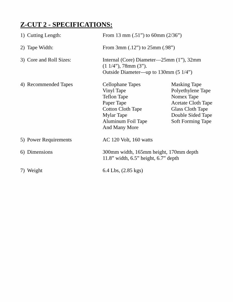
Z-CUT 2 - SPECIFICATIONS: 1) Cutting Length: From 13 mm (.51”) to 60mm (2/36”)
2) Tape Width: From 3mm (.12”) to 25mm (.98”)
3) Core and Roll Sizes: Internal (Core) Diameter—25mm (1”), 32mm
(1 1/4”), 78mm (3”). Outside Diameter—up to 130mm (5 1/4”)
4) Recommended Tapes Cellophane Tapes Masking Tape Vinyl Tape Polyethylene Tape Teflon Tape Nomex Tape Paper Tape Acetate Cloth Tape Cotton Cloth Tape Glass Cloth Tape Mylar Tape Double Sided Tape Aluminum Foil Tape Soft Forming Tape And Many More
5) Power Requirements AC 120 Volt, 160 watts
6) Dimensions 300mm width, 165mm height, 170mm depth 11.8” width, 6.5” height, 6.7” depth
7) Weight 6.4 Lbs, (2.85 kgs)

Z-CUT 2 - PARTS LIST: REFERENCE
NUMBER PART
NUMBER DESCRIPTION
1 725020 TURN TABLE FOR Z-CUT 2
2 725022 START SWITCH WITH BUTTON
3 725024 RATCHET BOARD AND GEAR SET
5 725026 SPLIT PLATE
6 725028 SPRING
7 725030 MICRO SWITCH LEVER WITH SCREW
9 725034 MICRO SWITCH SPRING
10 725036 SCREW (2 PC)
11 725038 BODY CASE
12 725040 MICRO SWITCH
14 725122 SAFETY COVER
15-16 725124 TAPE HOLDER SET (LEFT AND RIGHT)
17 725126 MICRO SWITCH COVER
18 725128 MICRO SWITCH
19 725130 KNOB WITH SCREW
21-24 725042 LOWER BLADE SET
25-26 725044 UPPER BLADE SET
27 725046 INWARD ARM
28 725048 SPRING AND SCREW
29 725050 TAPE BITE
30 725052 RUBBER STOPPER
31 725054 PIN (LARGE)
32 725056 PIN (SMALL)
33 725058 TAPE BITE BAR
34 725062 NUT
35 725064 A—CAM
36 725066 B—CAM
37 725068 C—CAM
38 725070 D—CAM
39 725072 E—CAM
40 725074 F—CAM
41 725076 CAM SHAFT
42 725078 ARM FRAME
43 725080 SPRING AND SCREW
44 725082 SPRING
45 725106 BASE

REFERENCE NUMBER
PART NUMBER
DESCRIPTION
46 725108 LEVER WITH SCREW
47 725110 LEVER WITH SCREW
48 725118 FUSE HOLDER
49 725120 RUBBER FOOT
50 725112 LEFT CHASSIS
51-54 725084 KNOB SET
55 725086 MOTOR CHASSIS
56 725088 LEVER WITH SCREW
57 725089 SPRING
58 725092 GEAR A WITH WASHER AND SCREW
59 725094 GEAR B
60 725096 GEAR C
61-62 725098 GEAR COVER AND SCREW ASSEMBLY
63 725100 MOTOR
64 725102 PINION GEAR
65 725104 MOTOR FAN
66 725135 TAPE SET LEVER WITH SCREW
67 725137 COIL SPRING
68 725139 LEVER
69 725136 BOBBIN GRAY ALL 3 PCS
70 725138 BOBBIN ORANGE LARGE 1 1/4”
71 725140 BOBBIN ORANGE SMALL 1”
720318 FUSE 2.0 AMPS
725440 ON/OFF SWITCH

Z-CUT 2 - PARTS IDENTIFICATION:

Z-CUT 2 - PARTS IDENTIFICATION CONTINUED:

Z-CUT 2 - PARTS IDENTIFICATION CONTINUED:

Z-CUT 2 - PARTS IDENTIFICATION CONTINUED:

Z-CUT 2 - PARTS IDENTIFICATION CONTINUED:


![BLADES [PPT]](https://static.fdocuments.in/doc/165x107/55cf9bc6550346d033a75508/blades-ppt.jpg)