YS-X4 Multi-Rotor Autopilot - HiModel.com mini value of throttle displays as 7 and the max as 90....
53
Copyright(C) 2012 Zero UAV All Rights Reserved. 1 YS-X4 Multi-Rotor Autopilot Quick Start Guide V1.0 www.zerouav.net Zero UAV (Beijing) Intelligence Technology Co. Ltd. October , 2012
Transcript of YS-X4 Multi-Rotor Autopilot - HiModel.com mini value of throttle displays as 7 and the max as 90....

Copyright(C) 2012 Zero UAV All Rights Reserved.
1
YS-X4 Multi-Rotor Autopilot
Quick Start Guide
V1.0
www.zerouav.net
Zero UAV (Beijing) Intelligence Technology Co. Ltd.
October , 2012

Copyright(C) 2012 Zero UAV All Rights Reserved.
2
1 In Box
■Hardware ●Software(Download)
Electronic Device■All-in-one Box (MC+ IMU) X11It is integrated with built-in Inertial Measurement Unit (IMU),
communicates with GPS/Compass and other external electronic
devices to carry out autopilot functionality.
2 Update firmware via PC RS232 serial port.
3 Display real time flying situation assist with GCS via bluetooth or wifi
module.
■GPS+Compass X1
It is for locating and sensing direction.
■LED Indicator X1
It is for indicating current flight states via blinking in different colours.
■Bluetooth Module X1
It is for communicating with the Bluetooth in Phone/Tablet.
■WIFI X1 (Data link can be added to extent range)
1 It is for communicating with the hot spot of Phone/Tablet.
2 It is for data communication by building up AP (Wireless Network).
■ Power Module X1
It is for connecting Battery and MC to provide power supply to YS-X4.
Input Voltage 3S~6S, output voltage5.7v
Accessory■GPS BracketX1
GPS/Compass is sensitive to magnetic interference, please use this bracket to
mount GPS module.
■3-PIN Servo Cable X8
Used to connect MC to RC Receiver.
■Sticker Paper X1 & Cable Label Paper X1
Used to mark different electronic devices and cables.

Copyright(C) 2012 Zero UAV All Rights Reserved.
3
■USB Cable X1
Used for connecting PC to MC and firmware upgrade.
■Warranty Information Card X1
It provides Product Serial No., Purchase Date. Please fill out related
information and return back to Zero UAV for registering your product
warranty.
Software (Download on website)●GS Software for Android System
●GS Software for PC Windows XP/7/SP3 system
●Firmware Program on PC.
●Firmware updating assistant.

Copyright(C) 2012 Zero UAV All Rights Reserved.
4
2 Assembly Assembly of Bluetooth Version
Assembly of WIFI Version & Navigator Version

Copyright(C) 2012 Zero UAV All Rights Reserved.
5
3 Power Supply & Magnetic Interference3.1 Power Supply
• The supply voltage of MC (Autopilot) is 5.7V. Power supply module, supply
range of which is 3S~6S (Power remains a little), namely 10.8V~25.5V,
output voltage 5.7v, is specially supplied by Zero UAV to connect battery
and MC ("POW port").
• MC provides 5.7v supply voltage to Bluetooth via CH8 port.
• The power supply range of WIFI is 3S~6S.
• MC provides power to RC receiver via CH1~CH7 port , no need to add any
out-built power module. S-Bus receiver only can be connected to port CH7.
• When using gimbal, user need to power on servo. Only leave one ESC
powered on if ESC has bec function. If without bec function, need to provide
extra power to servo and connect servo to any port of M1~M8.
3.2 Magnetic Interference
• When ESC and motors working, they will produce serious magnetic
interference, so GPS and magnetic sensor module must be installed by
nonferrous to keep far away from motor and ESC (especially Octo-rotor), and
the arrow on GPS must point to aircraft nose. Otherwise, the aircraft will fly
circling around and incorrectly hover.
• As there are rich electric current in the batterywire which can produce
magnetic field, users must place the batterywire far away from GPS and
magnetic sensor module, otherwise the craft will fly in circle in GPS mode.
Warning:When using video transmission, must keep the video transmission away from
IMU as far as possible, otherwise serious magnetic interference will occur!

Copyright(C) 2012 Zero UAV All Rights Reserved.
6
4 Data CommunicationThere are two ways of communicating YS-X4 and Phone/Tablet, via WIFI or
Bluetooth.
1)Via BluetoothStep1: Download YS-GCS.
It must be installed to the Mobile memory card. Android system can be
installed automatically via running file installation once in the file manager.
Step2 : Bluetooth Communication
Power on the Bluetooth Module on craft, then enable the Bluetooth of phone,
look for and connect the Bluetooth named“ZEROUAV”(Note: The letters must
be in Capital), Password :1234. If communication is successful, the Bluetooth
light will keep going on.
Only one Bluetooth name: ZEROUAV, Password:1234
NoticeOnly Android GCS is available when using Bluetooth to communicate with YS-
X4.
Step3 : Commissioning
Enable the GCS, Click on [Menu] and [Enable Bluetooth], then commissioning
can be started.
Copyright(C) 2012 Zero UAV All Rights Reserved.
7
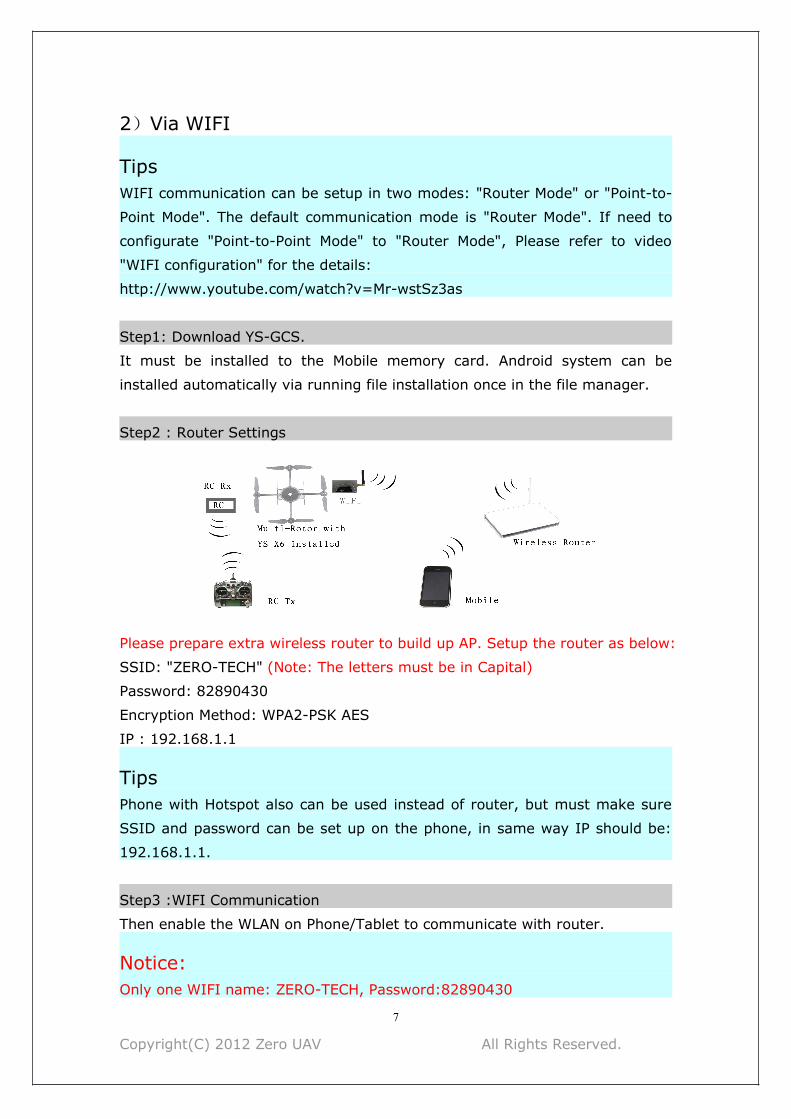
2)Via WIFI
TipsWIFI communication can be setup in two modes: "Router Mode" or "Point-to-
Point Mode". The default communication mode is "Router Mode". If need to
configurate "Point-to-Point Mode" to "Router Mode", Please refer to video
"WIFI configuration" for the details:
http://www.youtube.com/watch?v=Mr-wstSz3as
Step1: Download YS-GCS.
It must be installed to the Mobile memory card. Android system can be
installed automatically via running file installation once in the file manager.
Step2 : Router Settings
Please prepare extra wireless router to build up AP. Setup the router as below:
SSID: "ZERO-TECH" (Note: The letters must be in Capital)
Password: 82890430
Encryption Method: WPA2-PSK AES
IP : 192.168.1.1
TipsPhone with Hotspot also can be used instead of router, but must make sure
SSID and password can be set up on the phone, in same way IP should be:
192.168.1.1.
Step3 :WIFI Communication
Then enable the WLAN on Phone/Tablet to communicate with router.
Notice:Only one WIFI name: ZERO-TECH, Password:82890430
Copyright(C) 2012 Zero UAV All Rights Reserved.
8
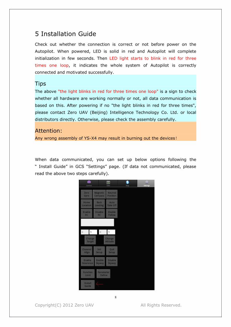
5 Installation GuideCheck out whether the connection is correct or not before power on the
Autopilot. When powered, LED is solid in red and Autopilot will complete
initialization in few seconds. Then LED light starts to blink in red for three
times one loop, it indicates the whole system of Autopilot is correctly
connected and motivated successfully.
TipsThe above "the light blinks in red for three times one loop" is a sign to check
whether all hardware are working normally or not, all data communication is
based on this. After powering if no "the light blinks in red for three times",
please contact Zero UAV (Beijing) Intelligence Technology Co. Ltd. or local
distributors directly. Otherwise, please check the assembly carefully.
Attention:Any wrong assembly of YS-X4 may result in burning out the devices!
When data communicated, you can set up below options following the
“ Install Guide” in GCS “Settings” page. (If data not communicated, please
read the above two steps carefully).

Copyright(C) 2012 Zero UAV All Rights Reserved.
9
Please strictly follow “Install Guide” shown as below:
(1)Channel Calibration.
(2)Check CH5 & CH6, set up F/S (Fails safe).
(3) ESC stroke calibration (“Yinghao” ESC is taken as an example here, this
step is no need for 500HZ ESC).
(4)Set up aircraft type and parameters. Fill in local magnetic declination (to
West is positive, to East is negative).
Please refer to the below website for magnetic declination
http://www.ngdc.noaa.gov/geomagmodels/struts/calcDeclination
http:// magnetic-declination.com/
(5)Check the configuration direction of IMU & GPS.
After the "Install Guide" completed, can start to fly in manual mode to have a
test.
TipsAbout RC transmitter
• RC transmitter must be set to "Fixed-Wing Mode". DO NOT set any mix-
control. All of the channels can’t be inverted on FUTABA RC transmitter, but
all of the channels on Jr and WFLY RC transmitters must to be inverted.
• For the RC transmitters of other branches, after channel calibration, check
whether the actual servo operation is the same as “Manual servo position”
showing on GCS, orientation/aileron/elevator display as "left/right and
push/pull", release RC transmitter displays as "Neutral position", the max
servo position is 40, example: the max value of left servo displays as left40;
the mini value of throttle displays as 7 and the max as 90.
The steps of "Install Guide" shown on GCS:

Copyright(C) 2012 Zero UAV All Rights Reserved.
10
"
1 Channel Calibration 2 Check CH5 & CH6 3 ESC stroke calibration
4Aircraft type & parameters 5Direction of IMU & GPS 6 Tips

Copyright(C) 2012 Zero UAV All Rights Reserved.
11
6 Compass Calibration
NoticeThere is no need to calibrate the magnetic compass in manual mode, and the
[Course Angle]” in "Data" page of GCS will keep displaying as 0.
But in GPS mode, compass calibration must be finished before take-off.
Ferromagnetic substances placed on multi-rotor or around its working
environment will affect the reading of earth magnetic for digital compass, it
also reduces the accuracy of the multi-rotor control, or even reads incorrect
heading. Calibration will eliminate such influences, and ensure MC system
performs well in a non-ideal magnetic environment.
The magnetic data will display once after calibration and be saved to the
autopilot.
Only in GPS mode, the actual course angle will display in [Course Angle]" in
"Data" page of GCS.
STEP1 Calibration in horizon:Enter Calibration by clicking [Magnetic Compass]-->[Horizontal Alignment]--
> [OK] to send the command to autopilot in “Setting” page of GCS.
After confirmation, the status bar in the middle will display "Success"
meaning the autopilot received the command of Horizontal Alignment, can
start the Calibration:
Rotate your aircraft 2~3 laps along with the horizontal surface, ask a helper
to monitor the [Attitude Angle] changing in "Data" page and try best to keep
the value of Pitch and Roll be smaller than 3 degree (you can also check the
LED light which is connecting with autopilot, if the light is keeping on it means
attitude is good, if the light is off it means the attitude is too big). After
completing 2-3 laps horizontal rotation, then go to the next step;
STEP2 Calibration in vertical:Rotate the craft nose vertically facing the ground, in GCS select
Enter Calibration by clicking [Magnetic Compass]-->[Vertical Alignment]-->
[OK] to send the command to autopilot in “Setting” page of GCS.
After "Success" displays in the status bar in the middle, it means the autopilot
received the command of Vertical Alignment and then the roll and pitch will
change close to 0 degree slowly via checking the [Attitude Angle] in “Data”
page (namely changed reference coordinate system, it’s level when the craft

Copyright(C) 2012 Zero UAV All Rights Reserved.
12
head face the ground).Then hold your Multi-rotor vertically and rotate it along
with its vertical axis keeping the attitude angle smaller than 3, after
completing 2-3 laps vertical rotation, then go to the next step; you can also
check the LED light which is connecting with autopilot, if the light is keeping
on it means attitude is good, if the light is off it means the attitude is too big.
STEP3 Calibration SavedAfter rotating, in "Settings" page of GCS click on [Magnetic Compass]--->
[Save Magnetic Compass]---[OK]. After finishing the calibration, GCS will goto "Control" interface automatically. After waiting for scores of seconds(the
purple light keeps going on during data reading, mobile will display the
magnetic sensor data of AP. Only need to observe the red and blue circles in
the middle of cross coordinates, if they are close to standard round, then it
indicates a successful calibration and data in good condition.
Two round circles will show whether the calibration was successful or not:
If two round circles show up in the "Control" interface (one blue circle one red
circle), calibration succeeds, can exit ;
If no circle or only one circle shows up in the "Control" interface, the
calibration has failed. Re-start from step1for re-calibration.
Successful Calibration Image:

Copyright(C) 2012 Zero UAV All Rights Reserved.
13
Notice:1. There is no calibration order in horizon and in vertical.
2. When “Horizontal Alignment” or “Vertical Alignment” button has been
pressed, please make sure to check whether current calibration command
displays in the data bar.
TipsAfter correct assembly and successful magnetic compass calibration once, no
need to recalibrate without any constructional reconfiguration or only upgrade
the firmware.

Copyright(C) 2012 Zero UAV All Rights Reserved.
14
7 Control Mode
Notices:• User must select two 3-position switches and set them to CH5 & CH6 by RC
transmitter.
• Manual/Manual Altitude Hold /GPS three modes can be switched through
CH5
(Note:the flight status on “Data” page of GCS separately displays as “Manual”
”Manual altitude hold” “Auto-hover”).
• CH6 can work only when CH5 stays at position 3 (namely GPS mode). CH6
is for switching modes among Auto-hovering/ Auto-navigation /Auto go home.
Notice• “X”: means irrelevant, any kind of status.• “RC status”: means “Receiver on” or “Receiver off” status in GCS。
Attention
RCStatus
CH5Status
CH6 Status Craft Status
Receiveron
CH5Position1
X
In full Manual Mode, it’s fully controlled byRC Transmitter only.Warning: Do not switch into GPS Modewhen flying in big actions or fast speed inManual Mode until flying gets into stable.
CH5Position2
X Manual Stabilize & Altitude Hold mode
CH5Positions3
CH6Position1
Craft Auto-hover, hover position can becontrolled by RC transmitter.
CH6Position2
Click on “Enable Waypoints” on Phone toenter “Auto-navigation" Mode (beforeenable the function please make surewaypoints are uploaded successfully)
CH6Position3
“Auto Go Home” Mode

Copyright(C) 2012 Zero UAV All Rights Reserved.
15
The receiver can't be shut down when using YS-X4.
8 Aircraft TypeTo coaxial propellers: Blue propeller is at Top; Purple propeller is at Bottom.
Otherwise all propellers are at top. The arrow means the orientation of
aircraft head should point to. Fill in “Aircraft Type” in the parameter settings
with below numbers.

Copyright(C) 2012 Zero UAV All Rights Reserved.
16
Customized parameters can be setup by self to allocate the mix-control of
motor. And the proportion coefficient of pitch, toll and turning of each motor
also can be customized for applying to the irregular Multi-rotor frame.
Warning• Very important: Please shut down the power supply of motors before
modifying customized parameters.
Customized Parameters Setup
Step 1First check out whether the customized parameters are correct or not, then
change “aircraft type” to 10.
WarningIf the parameters are not modified or incorrectly modified, propellers will
immediately rotate out of control when the "aircraft type" is changed to 10.
So to ensure your absolute safety, it's strongly suggested that Do NOT power
on motors before take off all of the propellers!
Step 2In GCS, please click on "Setting"-->[Parameters Define] to fill in the
parameters, make sure the parameters are totally correct, then change the
parameter of [Aircraft Type] to 10.
Step 3Then click on "Setting"-->[Parameters Define]-->[Get] to verify the changing
is successful. Repower autopilot on after verification, push the throttle stick to
the minimum position to make motor rotate in slow speed and meanwhile
carefully check whether the mix-control is consist with settings, after
verification can start to fly .
Customized Parameters•Customized parameters of [Throttle]: all of them must be 100.
• Customized parameters of [Course Angle]: to make the aircraft rotate to
right, the changing method of corresponding motor speed should be
decreased to -100, and increase to 100.

Copyright(C) 2012 Zero UAV All Rights Reserved.
17
• Customized parameters of [Pitch]: to make the aircraft head face the
ground, the changing method of corresponding motor speed should be
decreased to -100, and increase to 100.• Customized parameters of [Toll]: to make the aircraft roll to right, the
changing method of corresponding motor speed should be decreased to -100,
and increase to 100.
Now let’s take the Quad-X parameters setting for an example:
Copyright(C) 2012 Zero UAV All Rights Reserved.
18
9 Motors and Failsafe
Enable Motor ProtectionAny time after landing or before take-off, only if it is in Manual Mode and the
throttle stick is at the bottom position, motors can be locked up completely
after 5 seconds; After locked up, motors won't rotate even if push the throttle
stick. Only through “Enable Insurance” on phone or through Motor Arming,
motors can be unlocked.
Shut down motorOnly in manual mode and without holding altitude, the motors stop rotating
with pulling the throttle stick back to the bottom. Other time, if pull back the
throttle stick to the bottom, the motors won’t stop rotating but only decrease
altitude.
AttentionDuring flying, if there is no accidents please Do Not at the same time switch
to manual mode and push the throttle to the minimum, otherwise motors will
immediately shut down, craft will free-fall to the ground and never be
rebooted!
TipsWhenever need to stop the motors urgently, below ways can help:
(1) Switch CH5 to position 1, namely in Manual Mode but without holding
altitude, what’s more the throttle stick must be in the minimum.
(2) After Auto Go Home and landing on the ground, according to method (1);
RC Transmitter Signal LostUsers must refer to the instruction of RC transmitter to correctly set up F/S,
set CH5 to position 3,CH6 to position 3, throttle stick to the middle position
(installation guide has tips).
If enable F/S for any reason in “RC on” status, the autopilot will be switchedto Auto- hovering status(continue flight path for 5 seconds in Auto-waypoints
Mode, wait for 5 seconds and start to go home if the signal can’t recover after
5 seconds.
10 Flight

Copyright(C) 2012 Zero UAV All Rights Reserved.
19
10.1 Motor ArmingUnlock throttle: Move rod as V shape when the throttle is in the bottom. After
that push throttle stick in 5 seconds, motor can be enabled. But motor will be
locked up automatically if exceeding 5 seconds.
Notices:
Rod moving: Rudder in the left- most position, elevator in the bottom, aileron
in the right-most position,throttle in the bottom. For the right or left throttle,
user need to judge by self that the motor arming direction is V or reversd V .
After moving rod as V shaped, motor will not be enabled automatically, user
need to push the throttle stick to the minimum position to enable the motor
after moving rod.
Motor Arming
10.2 Vibrating and ShakingDuring flight, user need observe the “Vibrate State” and “Shake State ” in
“Data” page to judge the shaking status of IMU. In stable flight, it is normal
when the “Vibrate State“ and “Shake State ” range from 0~9, the smaller the
number the smaller the shaking, the number will directly affect flying
performance.
TipsVibrating coefficient: the maximum acceleration of alternate motion(vibrate)
in up/down,left/right,back/forth three directions.
Shaking coefficients: the maximum angular velocity of rotary movement
around X/Y/Z three axises.
10.3 Manual Servo Position and Real Servo PositionManual servo position
After channel calibration on transmitter, when user put the stick in the middle
position, the value of rudder, elevator and aileron in “Manual Servo Position”
in GCS should be in middle position. If user already has tuned but the manual
servo position is not near the middle position when releasing the sticks, need
to click on “Neutral Position” button in “Settings” interface to make the
autopilot record the correct center position of sticks.

Copyright(C) 2012 Zero UAV All Rights Reserved.
20
Real Servo Position
Real servo position is the relation of differential rotation speed outputted by
motor to keep aircraft stable during flight.
TipsUser can judge the balance of motors and propellers by observing the Real
Servo Position in level flying.
Example: when clockwise and anticlockwise propellers lose balance (suppose
clockwise motor is not level, the reaction torque generated by which is
smaller than that generated by anticlockwise motor), when in level flight and
heading unchangeable, the real rudder position will keep stable with left to
5~7. With the same pulse width output, the reaction torque generated by
clockwise motor is smaller than that generated by anticlockwise in the same
rotation speed, which lead aircraft rotate to the right, autopilot will output
levorotation torque automatically, namely the differential make the clockwise
rotation speed faster and anticlockwise slower. In this condition, aircraft can
fly normally and do not need hover any more, but the power consumption
and temperature of clockwise motor are higher than the anticlockwise motor’s.
At the same time, since the servo effect of clockwise is smaller than anti-
clockwise's, which will affect flying stabilization and cause shaking after
correction(especially for Quad-copter).
So, it is suggested that user need to precisely detect the balance and level
symmetry of motor and propeller to get a more stable flight. Until level flight
and hovering, if do not push rudder, the rudder of real servo position will be
smaller (about 1~2) or around neutral position.
10.4 Auto-takeoff and Auto-landing Semi-auto takeoff
When get 7 or more GPS satellites locks, switch CH5 to position 3 and CH6 to
position 1, that is the flight status is “Auto-hovering”, then move rod in V
shape before push the throttle stick. when throttle stick is more than 50%,
aircraft will take off automatically and auto-hover about 3 meters from the
ground getting into auto-hovering status.
Full-auto takeoff
Attention:Aircraft can take off fully-automatic only if the aircraft has completed semi-
automatic takeoff and the flying is successful.
Step 1
Copyright(C) 2012 Zero UAV All Rights Reserved.
21
Wait until get 7 or more GPS satellites locked, put the THR stick in the
minimum position, switch CH5 to GPS Mode (Position 3 ), CH6 to Position 1.
Step 2
Click on [Enable Insurance] or move rods as V shape to make the throttle
unlocked, then continue the next step within 5 seconds.
Step 3
Click on “Auto-takeoff ”, the aircraft will be powered on and take off slowly,
hovering in the height of 2~3 meters from ground.
Step 4
If the THR sticks is in the minimum position in auto-takeoff mode, only if
move the THR to the middle position can control the flying altitude.
NoticeAll of Rudder, Aileron and elevator can be controlled in Auto Take Off mode.
Please test semi-auto mode first and then test full-auto mode.
Auto go home
Autopilot can set the home position automatically when GPS has locked or
aircraft takes off in manual/auto mode.
In GPS mode, when switch CH6 to position 3 or select “Auto go home”-->
“OK” in GCS of mobile phone,AP will automatically go home after 5 seconds;
and the motor will auto-fly to 20 meters if the altitude is less than 20 meters;
during returning, the throttle servo is unavailable; autopilot will descent to
the ground automatically when reaching the start position and landing
position can be set; After enabling “Auto go home”, it can’t prevent autopilot
from returning and auto-landing even If switch CH6 back to “Auto-hovering”
or “Auto-navigation”, unless switch CH5 to Manual Position(Position 1 or 2)
and then back to Position Hold, hovering can be continued.
NoticeClick on “Motor off” -> “OK” to shut down the motor.
10.5 Click & GoMODE : GPS Auto-hover Mode
Step1:
Click any point on the map and it can appear a yellow smile there.
Step2:
Click on “FlyToPP” button in "Map" interface of GCS (the button will get gray if
no clicking exceeding several seconds, then need to click on the map once

Copyright(C) 2012 Zero UAV All Rights Reserved.
22
more to mae the yellow smile reappear), the yellow round smile will change
to purple star smile. Flying to the next position is same as above.
Warning:If the target point clicked on map is too far, the craft will possibly fly out of
sight, so user need to be cautious when using the Fly to Point function.
10.6 Target Lock & Fly EncircleMODE: Auto-hover mode
Solution1:Step1:
It will appear a yellow smile while clicking any point on the map;
Step2:
Click [PTZ Lock] button in "Map" interface. When yellow round smile changed
to purple star smile, the aircraft head will keep facing the target point;
Solution2:Step1:
In any time (including before takeoff or manual/auto mode after takeoff)
fly/take the craft to the target point to be locked , then within 3 seconds
switch between position1 and position3 on CH6 for three times (that is 1->3-
>1->3->1->3->1 ), FC will record the longitude&latitude of GPS as the
target point to be locked.
Step2:
In GPS Auto-hover mode, within 3 seconds switch between position1 and
position2 on CH6 for three times(do not switch to position3 which is invalid,
that is 1->2->1->2->1->2->1 ), then FC will enter Target Lock & Fly Encircle
Mode.
TipsAfter target point locked according to solution1 or solution2, users can operat
flying by transmitter.
Remark1: When left aileron outputs in RC interface, the aircraft will hover
clockwise around the target point. When the right aileron outputs, it will
hover anti-clockwise.
Remark2: Pushing the stick can decrease the hovering radius and drag the
stick can increase the hovering radius. Do Not push or pull sticks if Target

Copyright(C) 2012 Zero UAV All Rights Reserved.
23
Lock enabled but hovering radius is not enough, only need to push aileron
stick until craft start to hover.
Remark3: Only when selecting “Quit PTZ Lock” in "Tools” interface or switch
back to Manual Mode, the elevator and aileron can be controlled normally.
10.7 Waypoints Flying
Step1:In "Map" interface of GCS, click [Tools]-> [Design Waypoints] to design the
flying path. Click on map once can get one waypoint, get all waypoints one by
one. Click [Default Tool] to complete the waypoints design.
TipIf the firmware version is later than Sept.15th, 2012, "Height", "Hovering
time","Speed" and other key parameters are added to each waypoint, so
must make sure to click each waypoint to select "Edit waypoint" and correctly
setup.
"Height" indicates the point where craft is staying, which can be set as
negative value below zero(when the takeoff position is too high and the craft
need to fly under the takeoff position). If the height between two waypoints
are different, craft will climb up. The default value of height is 9999, that is to
say since the altitude is too high to reach, craft will fly according to the
current height.
"Hovering time" means the time that craft stays in the present position before
going to the next waypoint(the default hovering time in first waypoint is
65535 seconds ).
"Speed" means the flying speed that craft flies to the next waypoint from
present position.
Step2:After the waypoints design is completed, it can be saved as file which can be
used next time. User can also click on [Upload Waypoints] to upload the
flying path to Autopilot. Please check whether each waypoint has been
changed
to blue or not, if blue it means uploading is successful (orange is not
successful), and then get into [Target Point] to check whether the number
displays there is the same as uploaded waypoints, if not need to upload once

Copyright(C) 2012 Zero UAV All Rights Reserved.
24
more; If any waypoint is not changed to blue, please also upload the
waypoints once more.
Step3:Click [Remove Waypoints] to make the blue waypoints recover to red; then
Select [Verify Waypoint] from “Tool” interface, load waypoints from Autopilot
to Ground Station for comparing, if all waypoints are blue it means the
uploaded waypoint path is the same as that in Ground Station and waypoints
verification is successful. Otherwise need to upload waypoints once more.
Step4:Switch CH5 to Position 3 and CH6 to Position 2, then click on [Enable
Skyway] in "Setting" interface of GCS, the craft will fly to the first waypoint
and hover there. Set [Change Target] as 2 and upload it, then craft will fly inorder to waypoint 2、3、4...and fly back to waypoint 1 and hover there after
finishing all waypoints.
NoticeIf waypoints incorrectly uploaded, when switch to Auto-navigation Mode the
aircraft will fly far away automatically and out of control.
Free Course ModeGenerally, when it's waypoints mode, craft nose faces flying orientation in
real time. When user want to freely control the course of craft, in Waypoints
Mode can click on [Intelligent Course Locked] in "Setting" interface of GCS.
After that the "Intelligent Course Locked] doesn't mean Care Free function, it
means Free Course Mode. That is though craft will fly according to skyway,
the craft nose will not face the flying orientation in real time, and the course
of craft can be freely controlled by rudder on RC transmitter.
Click on [Disable Intelligent Course Locked] and [OK], then the craft nose will
face flying orientation again.
10.8 Follow MeThis function only can be used in the condition that GPS on phone is enabled
and meanwhile GPS of this phone has been located showing on “Data”
interface of GCS.
In GPS Hover Mode, after all the sticks on transmitter are set in the neutral
position, user can click on [Enable Follow] in “Setting” interface, the craft can

Copyright(C) 2012 Zero UAV All Rights Reserved.
25
fly following the mobile phone GPS and the craft nose orientation will be
locked.
If to quit this function, just click on [Disable Follow] on “Setting” interface.
10.9 Care FreeOnly in GPS Hover Mode, "Carefree" is available.
Option 1
Click on [Enable Course Locked] button in "Setting" interface, autopilot can
record the current orientation of craft head. Then users can freely adjust the
orientation of craft head with rudder stick; when users operate the left/right
aileron and push/pull sticks on transmitter, the autopilot will fly to the
orientation according to the course being locked, not the current orientation
of craft head.
Option 2
Within 5 seconds please switch between position1 and position2 on CH6 for
five times (do not switch to position3 which is invalid, that is 1->2->1->2-
>1->2->1->2->1->2->1 ), then FC will enter "Care Free Mode".
To exit "Care Free", click on [Disable Course Locked] button in "Setting"
interface or switch to Manual Mode.
11 Parameter Setup
Default ParametersThe Factory Default Parameters are shown as below. It is the Quad-X flying
mode and can be applied to most crafts for flying.
Copyright(C) 2012 Zero UAV All Rights Reserved.
26
Notice”PTZ Roll Sensitivity” & “PTZ Pitch Sensitivity” can directly affect the touch
sensitivity of transmitter.
Please Do NOT change the default parameters of Roll/Pitch,THR P/I,Rotate
P/D. If parameters are incorrectly changed, can push the THR to the
minimum and switch to Manual Mode, then click on [Default Settings] in
"Setting" interface, the parameters can recover to factory defaults.
The meaning of other parameters are described as below:
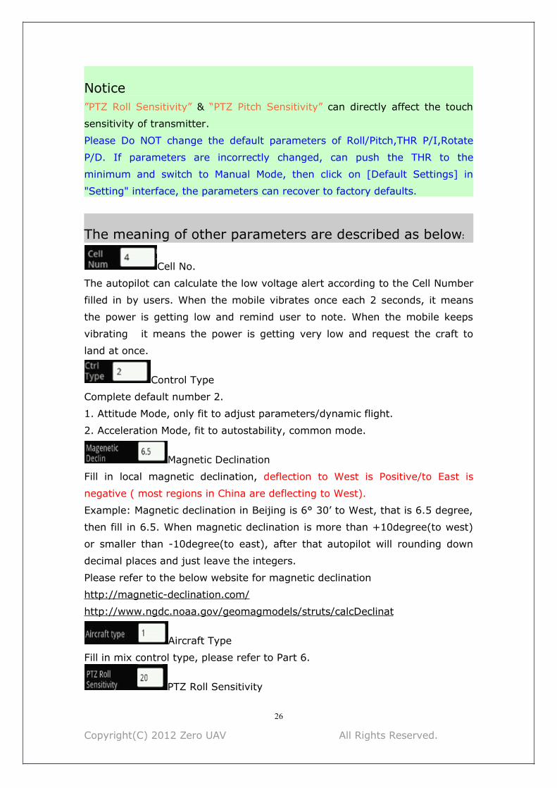
Cell No.
The autopilot can calculate the low voltage alert according to the Cell Number
filled in by users. When the mobile vibrates once each 2 seconds, it means
the power is getting low and remind user to note. When the mobile keeps
vibrating it means the power is getting very low and request the craft to
land at once.
Control Type
Complete default number 2.
1. Attitude Mode, only fit to adjust parameters/dynamic flight.
2. Acceleration Mode, fit to autostability, common mode.
Magnetic Declination
Fill in local magnetic declination, deflection to West is Positive/to East is
negative ( most regions in China are deflecting to West).
Example: Magnetic declination in Beijing is 6° 30’ to West, that is 6.5 degree,
then fill in 6.5. When magnetic declination is more than +10degree(to west)
or smaller than -10degree(to east), after that autopilot will rounding down
decimal places and just leave the integers.
Please refer to the below website for magnetic declination
http://magnetic-declination.com/
http://www.ngdc.noaa.gov/geomagmodels/struts/calcDeclinat
Aircraft Type
Fill in mix control type, please refer to Part 6.
PTZ Roll Sensitivity
Copyright(C) 2012 Zero UAV All Rights Reserved.
27
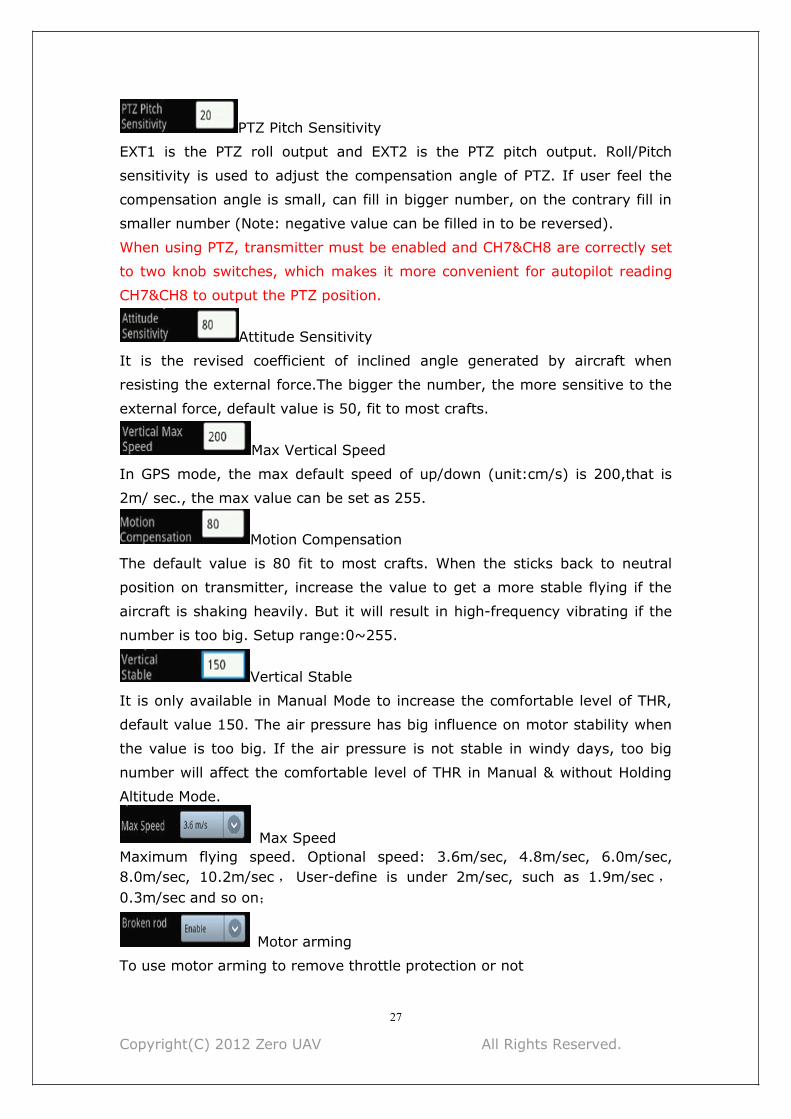
PTZ Pitch Sensitivity
EXT1 is the PTZ roll output and EXT2 is the PTZ pitch output. Roll/Pitch
sensitivity is used to adjust the compensation angle of PTZ. If user feel the
compensation angle is small, can fill in bigger number, on the contrary fill in
smaller number (Note: negative value can be filled in to be reversed).
When using PTZ, transmitter must be enabled and CH7&CH8 are correctly set
to two knob switches, which makes it more convenient for autopilot reading
CH7&CH8 to output the PTZ position.
Attitude Sensitivity
It is the revised coefficient of inclined angle generated by aircraft when
resisting the external force.The bigger the number, the more sensitive to the
external force, default value is 50, fit to most crafts.
Max Vertical Speed
In GPS mode, the max default speed of up/down (unit:cm/s) is 200,that is
2m/ sec., the max value can be set as 255.
Motion Compensation
The default value is 80 fit to most crafts. When the sticks back to neutral
position on transmitter, increase the value to get a more stable flying if the
aircraft is shaking heavily. But it will result in high-frequency vibrating if the
number is too big. Setup range:0~255.
Vertical Stable
It is only available in Manual Mode to increase the comfortable level of THR,
default value 150. The air pressure has big influence on motor stability when
the value is too big. If the air pressure is not stable in windy days, too big
number will affect the comfortable level of THR in Manual & without Holding
Altitude Mode.
Max SpeedMaximum flying speed. Optional speed: 3.6m/sec, 4.8m/sec, 6.0m/sec,8.0m/sec, 10.2m/sec, User-define is under 2m/sec, such as 1.9m/sec,0.3m/sec and so on;
Motor arming
To use motor arming to remove throttle protection or not

Copyright(C) 2012 Zero UAV All Rights Reserved.
28
Protection
Whether to enable the THR protection or not
Overload control
The acceleration of craft in GPS Hover Mode is optional.
Soft, Common and Hard
NoticeThe 4 parameters below need to be filled in when Flight Controller is used for
the first time, when filling in the values must make sure the THR stick is in
the bottom;
Click on “Settings”[Enter Setting], when “Setting Status” displays in “Data”
interface can update the parameters. Then click on [Send] to give the
command to autopilot and click on [Get] to confirm the update is correct.
After verifying, click on “Settings” [Exit Setting], then can start to fly .

Copyright(C) 2012 Zero UAV All Rights Reserved.
29
Remote Control Mode
User can select the options below according to yourself RC transmitter mode.
PLEASE SET UP CAREFULLY!
Self-adaptive: AP will auto select the options according to the RC Tx being
used.Attention:The RC Tx must be enabled first before autopilot enabled.
Ordinary : Ordinary FUTABA Receiver, AP CH1 connect to Receiver CH1, AP
CH2 connect to Receiver CH2.
S-BUS: Only connect AP CH7 to the Receiver S-BUS port.
PPM: PPM is supported, connect AP CH8 to Receiver PPM port.
Volt Alert Threshold
Fill in the alert voltage of each battery which is been using, need user to fill in
after measuring by self. Usually fill in 3.65.
ESC Type
Fill in the ESC type which is been using.
WarningFault filling of NORMAL ESC(400HZ) and XA ESC(500HZ) will result that the
propellers go out of control after power connected, very dangerous!
Steering Gear Frequency
Input the correct value according to your servo type: 50HZ for Analog Servo,
250HZ and 333HZ for Digital Servo.

Copyright(C) 2012 Zero UAV All Rights Reserved.
30
12 Craft Shaking AdjustmentStep 1
Deviation of installation /vibration/shaking will make the test of flying status
by IMU delayed. So user need to check whether the installation direction of
IMU is correct and try to install it in a stable place on craft where there is no
resonance.
NoticeThe IMU of YS-X4 has damper inside, so there is no need using external
damper.
The vibration coefficient and shaking coefficient showing on GCS mean the
shaking status of IMU. Before configurate motors and propellers, users must
make balance test to reduce the vibration and shaking coefficient smaller
than 10, the smaller the better.
Step 2
The attitude of Multi-rotor is up to motor speed adjustment, so servo
sensitivity will directly affect the accuracy of Multi-rotor attitude adjustment.
User need to adjust weight and pitch of propeller to be proper, so that motors
can rotate in enough speed and generate enough servo effect. For the craft
seeking for high efficient configuration, it is inevitable that the flight stability
will reduce, user only can select one between flight efficiency and stability;
Step 3
The symmetry of Multi-rotor has significant effect on flying stability. In
quarter 3 “real servo position” of Part 9, user can estimate the symmetry of
motor and propeller in level flight. If fail to adjust the symmetry, must spend
more energy on frame and dynamic configuration;
Step 4
If the problem of three steps above are solved, can adjust [Toll Sensitivity],
[Pitch Sensitivity] in “ Parameters Setting”, that is to set the strength of
correction of craft ; And adjust [Motion Compensation], that is to set the
correction of stabilization of craft to realize a limited adjustment.

Copyright(C) 2012 Zero UAV All Rights Reserved.
31
Note“Toll sensitivity”, “Pitch sensitivity” have been set the correction value with
same angular velocity error, 60 is default, the bigger the sensitivity value the
quicker the correction, that is the manual control is more flexible. But too big
sensitivity value will lead to high-frequency vibrating, so need to decrease the
sensitivity value for high-speed craft (smaller propellers).
“Motion compensation” is set for correction of low-speed craft shaking,
default value is 80. Without the compensation, since the servo effect of low-
speed craft (bigger propellers) is too small, when sticks on transmitter back
to neutral position, the craft will jerk to be stable. User can gradually increase
the “Motion Compensation” value to get the best stabilize effect without
jerking when the sticks back to neutral position. But for the high-speed craft
(smaller propellers), the value should be decreased, otherwise the craft will
highly-frequency vibrate. The minimum value of the parameter is 0 and the
max value is 255.

Copyright(C) 2012 Zero UAV All Rights Reserved.
32
13 Related Electronic Device
Power Management ModuleWhen YS-X4 and power management module connected, discharge current
and battery consumption can be seen directly in “Data ” interface of GCS.
Operation Steps1) Connect power management module with YS-X4 (to AI1 port of YS-X4)
2) Push the throttle stick to the bottom position
3) Repower on YS-X4
4) After powered, FC will zero sensor automatically, the discharge current
(ampere A) and battery consumption(MAH) start to be output according to
the detection by power management module.

Copyright(C) 2012 Zero UAV All Rights Reserved.
33
Data Link
Tips• Datalink XB-PRO900 is used to extend communication distance, making the
GCS control distance avoid from WIFI distance limit.
• Data link XB-PRO900 Technical Specifications
Transmitted power: 100 mW
Frequency : 900 MHZ
Communication Distance: not less than 2 ~ 3 km (open areas).Physical Port :RS232
Communication Baud Rate :115200 BPS.
• A pair of datalink XB-PRO900 contains two data links, one is on craft and
another on ground station. But the encapsulations are same and can be
interchanged.(1)Data Link (on Craft) Connection
Install one data link on craft instead of Bluetooth/WIFI module, connect the
data link to YS-X4 COM port referring to Bluetooth/WIFI module connection.
Power supply of Data link is 3S~6S.
Data link on Craft(2)Data Link (on ground) Connection
Connect Bluetooth/WIFI module with another data link on ground (using line
coming with data link), which can supply power together with wireless router
on ground. That is there are three parts on the ground:Data Link,Wireless
Router.

Copyright(C) 2012 Zero UAV All Rights Reserved.
34
Notice• Data link is powered by 3 S ~ 6 S lithium battery, the power line is in red-
black two colours, red is positive pole and black is negative pole.
14 Firmware UpgradeThe upgrade of YS-X4 firmware is very simple. Before upgrade, please
download the special firmware upgrade tool on Zero UAV official website:
http://www.zerouav.net/kefu.aspx
USB Cable Connection: plug one end of USB cable to PC USB port , and the
other end to FC COM port.
Upgrade Steps:
Step1
NoticePlease Do Not enable the power of FC when upgrading. If enabled please shut
off the power.
Enable the special programme "YS-X4 PC Firmware Upgrade" for upgrade
,click on "AP Firmware Upgrade",the software will be enabled and shown as
below:

Copyright(C) 2012 Zero UAV All Rights Reserved.
35
Step2Select COM port of PC to upgrade (Note: if do not know which COM to use
on PC, please click with right mouse “My Computer”->“Attribute”->"Device
Manager”->“Port”(COM/LPT) to have a check).
Click on “Config COM”, then setup its property (as the diagram below):
Baud rate: 115200
Data bite: 8
Parity: None
Stop bit: 1
Data flow control: None
When setting finished, click on

Copyright(C) 2012 Zero UAV All Rights Reserved.
36
Step3
Click on button, Select a “.arm” file offered by Zero UAV to
upgrade(shown as below diagram).
Step4Repower on the FC and the upgrade will be enabled automatically. When it
says in red words “Please Restart AP!”, then autopilot can be powered off.
Warning

Copyright(C) 2012 Zero UAV All Rights Reserved.
37
1,When all settings are finished, if repower on AP but the upgrade software
doesn’t work, please disable the software and replug the USB cable.
2, when select firmware versions, the below warning shows up
Please redownload the upgrade firmware or update the date later than the
present date(within 30days) , then upgrade once more.

Copyright(C) 2012 Zero UAV All Rights Reserved.
38
15 Warning and Declaimer1. The manual contains information about installation, debugging and how to
use the product. Please read it thoroughly before using the product.
2. Zero UAV (Beijing) Intelligence Technology Co. Ltd. assumes no liability for
damage(s) or injuries incurred directly or indirectly from the use of this
product.
3. Please keep far away from the crowd, children and property when using the
product.4.Install propeller after completing all the debugging and checking, to avoid
damage(s) or injuries.
5. When any of the following events or incidents has taken placed, we will not
offer any warranty and service:
(1) The product has been repaired, modified, or any parts of the product have
been substituted or replaced by anyone not expressly authorized by Zero UAV.
(2) The warranty card, the serial number of the hardware and the flight data
or any of these items is lost.
(3) Damaged caused by use's faults such as attempting wiring not in
accordance with the manual, which may cause short circuit.
6 This product and manual are copyrighted by Zero UAV with all rights
reserved. No part of this product or manual shall be reproduced in any form
without the prior written consent or authorization of Zero UAV. No patent
liability is assumed with respect to the use of the product or information
contained herein.
Copyright(C) 2012 Zero UAV All Rights Reserved.
39
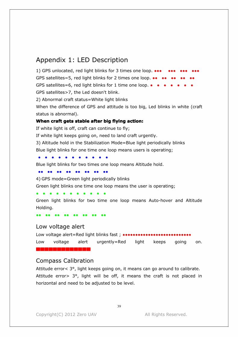
Appendix 1: LED Description1) GPS unlocated, red light blinks for 3 times one loop. ●●● ●●● ●●● ●●●
GPS satellites=5, red light blinks for 2 times one loop. ●● ●● ●● ●● ●●
GPS satellites=6, red light blinks for 1 time one loop. ● ● ● ● ● ● ●
GPS satellites>7, the Led doesn't blink.
2) Abnormal craft status=White light blinks
When the difference of GPS and attitude is too big, Led blinks in white (craft
status is abnormal).
WhenWhenWhen
When
craftcraftcraft
craft
getsgetsgets
gets
stablestablestable
stable
afterafterafter
after
bigbigbig
big
flyingflyingflying
flying
action:action:action:
action:
If white light is off, craft can continue to fly;
If white light keeps going on, need to land craft urgently.
3) Altitude hold in the Stabilization Mode=Blue light periodically blinks
Blue light blinks for one time one loop means users is operating;
● ● ● ● ● ● ● ● ● ● ●
Blue light blinks for two times one loop means Altitude hold.
●● ●● ●● ●● ●● ●● ●● ●●
4) GPS mode=Green light periodically blinks
Green light blinks one time one loop means the user is operating;
● ● ● ● ● ● ● ● ● ● ●
Green light blinks for two time one loop means Auto-hover and Altitude
Holding.
●● ●● ●● ●● ●● ●● ●● ●●
Low voltage alertLow voltage alert=Red light blinks fast ; ●●●●●●●●●●●●●●●●●●●●●●●●●●●
Low voltage alert urgently=Red light keeps going on.
▇▇▇▇▇▇▇▇▇▇▇▇▇
Compass CalibrationAttitude error< 3°, light keeps going on, it means can go around to calibrate.
Attitude error> 3°, light will be off, it means the craft is not placed in
horizontal and need to be adjusted to be level.

Copyright(C) 2012 Zero UAV All Rights Reserved.
40
After Magnetic data calibration, the Purple light keeps going on during data
reading. LED will get normal when data reading is finished.
▇▇▇▇▇▇▇▇▇▇▇▇
Abnormal Electronic DeviceBarometer, IMU and GPS abnormal, white light keeps going on.
Appendix2: Port DescriptionMC
A/CH1 Aileron-For roll control (left/right)
E/CH2 Elevator-For pitch control (front/back)
T/CH3 Throttle-For throttle control
R/CH4 Rudder-For rudder control
CH5 Manual/Auto Mode Switch
CH6 Auto-Hover/Auto-waypoints/Returning&Landing Switch
CH7 For gimbal pitch servo control/ Or for S-BUS
CH8 For gimbal roll servo control/ Or for PPM receiver
AI1 Connect Power Calculate Module
POW To AP Power Supply
GPS-R To GPS power
GPS-B To GPS data
M1 Motor 1
M2 Motor 2
M3 Motor 3
M4 Motor 4
M5 Motor 5
M6 Motor 6
Y1 Motor 7/ Gimbal Roll
Y2 Motor 8/ Gimbal Pitch
COM Connect RS232 port and to PC for firmware upgrades.

Copyright(C) 2012 Zero UAV All Rights Reserved.
41
Appendix 3: GCS Interface IntroductionThe software interface:
Buttons and Functions
No. Buttons Functions
1 Remote Control Unavailable for YS-X4
2 Data Real time flight data
3 Map Real time map or saved map
4 Settings Setup various states of craft
5 Parameters Adjust craft parameters
6 Cross Interface Unavailable for YS-X4
7 The Cross Unavailable for YS-X4
8 Round Circle in
Cross
Unavailable for YS-X4
9 Enable/Disable
Remote Control
Unavailable for YS-X4
10 Quit Quit from GCS
11 Enable/Disable
Attitude
Control
Unavailable for YS-X4
12 Net
Information
Used to set service information
13 Enable
Bluetooth
Used to enable Bluetooth
Copyright(C) 2012 Zero UAV All Rights Reserved.
42
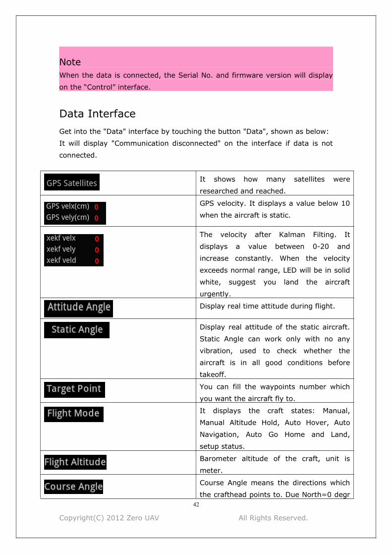
NoteWhen the data is connected, the Serial No. and firmware version will display
on the “Control” interface.
Data InterfaceGet into the "Data" interface by touching the button "Data", shown as below:
It will display "Communication disconnected" on the interface if data is not
connected.
It shows how many satellites were
researched and reached.
GPS velocity. It displays a value below 10
when the aircraft is static.
The velocity after Kalman Filting. It
displays a value between 0-20 and
increase constantly. When the velocity
exceeds normal range, LED will be in solid
white, suggest you land the aircraft
urgently.
Display real time attitude during flight.
Display real attitude of the static aircraft.
Static Angle can work only with no any
vibration, used to check whether the
aircraft is in all good conditions before
takeoff.
You can fill the waypoints number which
you want the aircraft fly to.
It displays the craft states: Manual,
Manual Altitude Hold, Auto Hover, Auto
Navigation, Auto Go Home and Land,
setup status.
Barometer altitude of the craft, unit is
meter.
Course Angle means the directions which
the crafthead points to. Due North=0 degr
Copyright(C) 2012 Zero UAV All Rights Reserved.
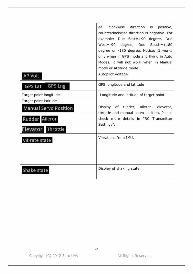
43
ee, clockwise direction is positive,
counterclockwise direction is negative. For
example: Due East=+90 degree, Due
West=-90 degree, Due South=+180
degree or -180 degree. Notice: It works
only when in GPS mode and flying in Auto
Modes, it will not work when in Manual
mode or Attitude mode.
Autopilot Voltage
GPS longitude and latitude
Target point longitude Longitude and latitude of target point.
Target point latitude
Display of rudder, aileron, elevator,
throttle and manual servo position. Please
check more details in "RC Transmitter
Settings".
Vibrations from IMU.
Display of shaking state

Copyright(C) 2012 Zero UAV All Rights Reserved.
44
Map Interface
+: Zoom in
- :Zoom out
Map: map mode.
Satellite: satellite mode
Tips:
1 The map which you used last time was saved in default, when you open it
next time, it shows up the saved map.
2 There is no network. Enable WIFI, cached data can be displayed.
Nitices:
Cached map: when network is on, enable the software to download the map.
If finishing downloading the cached map, if enable WIFI, the cached map will
be displayed.
Locate

Copyright(C) 2012 Zero UAV All Rights Reserved.
45
After the GPS was located, click this button can find where your aircraft
locates.
Phone/Tablet position. The GPS of Phone/Tablet need to be enabled.
Search the position where you want to check.
Save the current position on map.
Load the saved position on map.
Fly to Point Fly. Please check "Fly To Point Fly" page.
Target Lock Fly. Please check "Target Lock Fly" page.

Copyright(C) 2012 Zero UAV All Rights Reserved.
46
Click it to enter editing waypoints, please check " Waypoints Fly" Page.
Locate FlytoPP/PTZLock: Move Map center to operation area.
Exit FlytoPP/PTZLock: Remove the FlytoPP/PTZLock mode.
Waypoint edition
Click on waypoint, there will be a text box display as below:
Single waypoint edit
Used to edit waypoint attribute, such as longitude and latitude, altitude and
speed.
Single waypoint upload
To upload the waypoint.
Single waypoint delete
To delete the waypoint
Number
Waypoint number.
Altitude
The height of waypoint, unit: meter
Longitude
Longitude of this waypoint.
Latitude
Latitude of this waypoint.
Hovering time
Time of hovering, unit is second, zero means no hover(the default hovering
time is 65533 seconds of first waypoint).
Camera setting
Optional of camera attribute.

Copyright(C) 2012 Zero UAV All Rights Reserved.
47
Target speed
It means the flying speed of craft from present position to next waypoint.
Settings Interface
Notice:
All operations in settings are vitally important, please operate seriously.
Click it enter into "Magnetic Compass" Calibration.
It's used to capture Neutral Position after flight and Transmitter adjustments,
please operate it by manually in no wind.
Notes: When capture neutral position, please move all sticks to middle
position. It has nothing to do with THR position.
It's used to change home position or record new home position.
Auto Go Home and Landing. After the aircraft reaches home location, the craft
can be controlled manually.

Copyright(C) 2012 Zero UAV All Rights Reserved.
48
Take off fully automatically, please check Part 9 (3) “Auto Take Off".
Enable receiver/ Disable receiver
Notice : The receiver can't be disabled for YS-X4.
This function can be used only when your phone has GPS hardware and got
more than 5 satellites locked, and in Auto-hover mode. After enabled Follow
Me, the aircraft will fly automatically following mobile GPS location.
Notice: Generally, phone position has error about 5~10 meters.
In Auto Navigation mode, fill in the new waypoint number which
you will fly to.
Attention:
Fill in a number which is in the range of uploaded waypoints number.
In Auto-Hover mode, it's used to set flight altitude, put in altitude needed
here. Example: filling in 10 means setting flight altitude as 10 meters.
Please confirm to align the channel without any electric power connected.
Example: When moving Throttle stick as Minimum-Maximum-Minimum, if
GCS data displays as below: Manual Throttle is 7 when Throttle stick is at
the Minimum position and 90 when at the Maximum position, that means
Channel Align is completed successfully.
Special Attention
Copyright(C) 2012 Zero UAV All Rights Reserved.
49
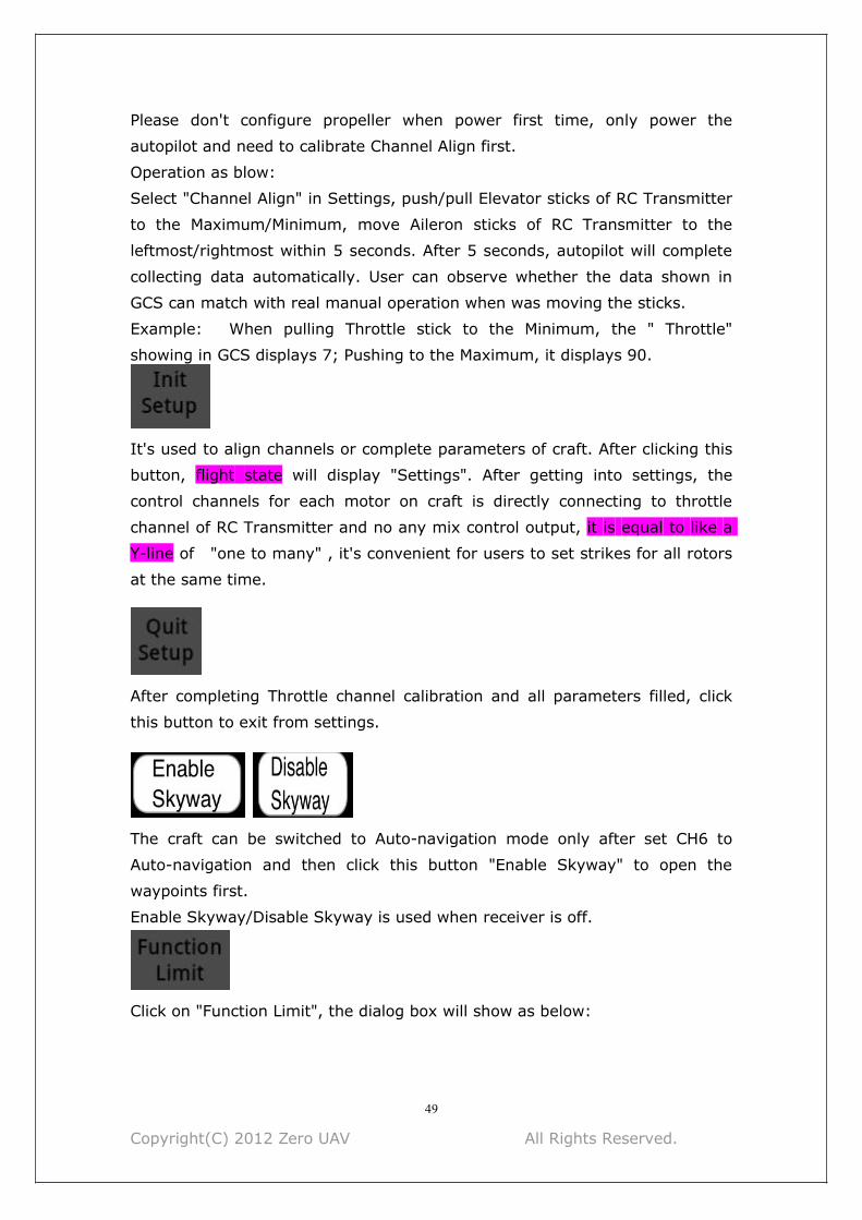
Please don't configure propeller when power first time, only power the
autopilot and need to calibrate Channel Align first.
Operation as blow:
Select "Channel Align" in Settings, push/pull Elevator sticks of RC Transmitter
to the Maximum/Minimum, move Aileron sticks of RC Transmitter to the
leftmost/rightmost within 5 seconds. After 5 seconds, autopilot will complete
collecting data automatically. User can observe whether the data shown in
GCS can match with real manual operation when was moving the sticks.
Example: When pulling Throttle stick to the Minimum, the " Throttle"
showing in GCS displays 7; Pushing to the Maximum, it displays 90.
It's used to align channels or complete parameters of craft. After clicking this
button, flight state will display "Settings". After getting into settings, the
control channels for each motor on craft is directly connecting to throttle
channel of RC Transmitter and no any mix control output, it is equal to like a
Y-line of "one to many" , it's convenient for users to set strikes for all rotors
at the same time.
After completing Throttle channel calibration and all parameters filled, click
this button to exit from settings.
The craft can be switched to Auto-navigation mode only after set CH6 to
Auto-navigation and then click this button "Enable Skyway" to open the
waypoints first.
Enable Skyway/Disable Skyway is used when receiver is off.
Click on "Function Limit", the dialog box will show as below:

Copyright(C) 2012 Zero UAV All Rights Reserved.
50
click "Get"
Users can observe the functions which have been opened or not in yourself FC.
User can define the parameters by yourself.
Copyright(C) 2012 Zero UAV All Rights Reserved.
51
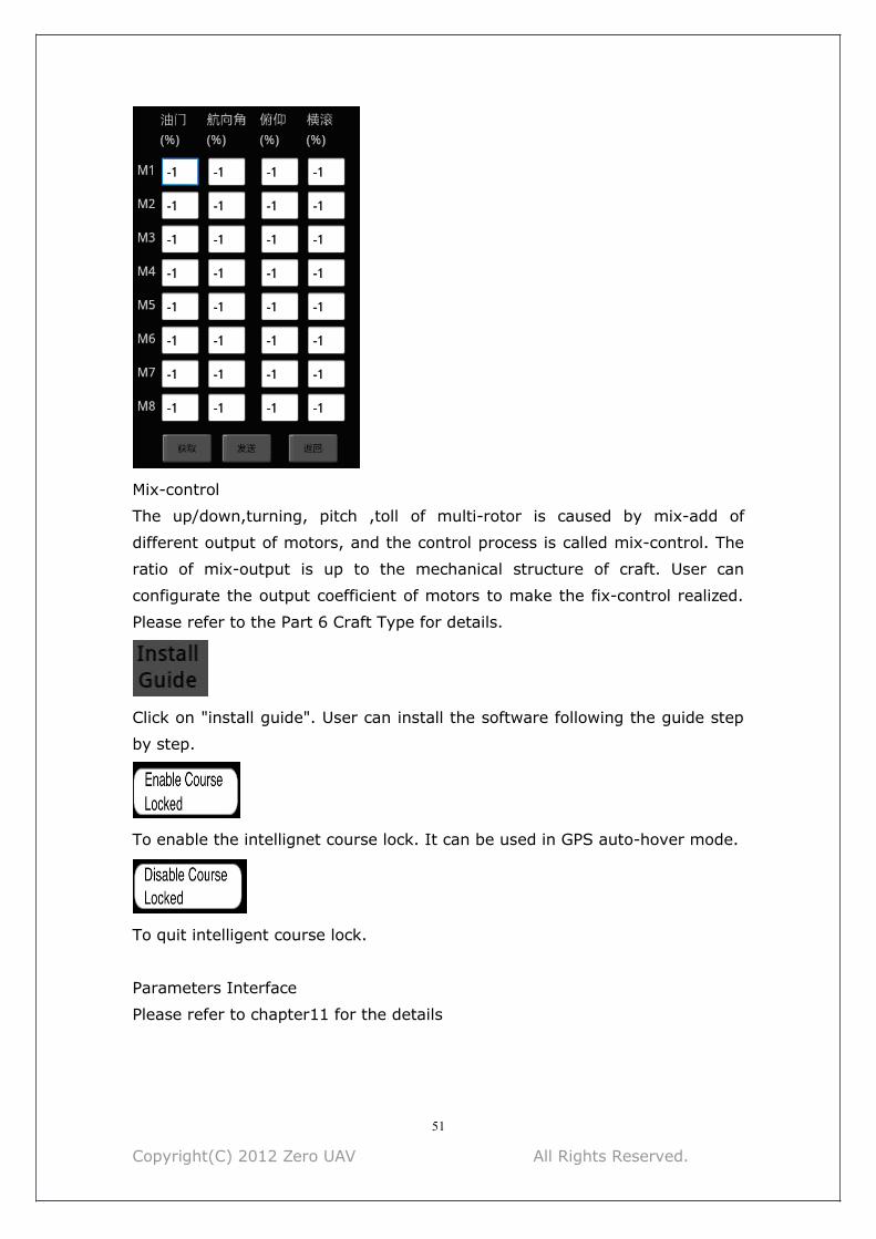
Mix-control
The up/down,turning, pitch ,toll of multi-rotor is caused by mix-add of
different output of motors, and the control process is called mix-control. The
ratio of mix-output is up to the mechanical structure of craft. User can
configurate the output coefficient of motors to make the fix-control realized.
Please refer to the Part 6 Craft Type for details.
Click on "install guide". User can install the software following the guide step
by step.
To enable the intellignet course lock. It can be used in GPS auto-hover mode.
To quit intelligent course lock.
Parameters Interface
Please refer to chapter11 for the details

Copyright(C) 2012 Zero UAV All Rights Reserved.
52
Appendix4 Technical SpecificationsBasic performance
Multi Rotor Types supported
Quad-Rotor: +4, x4;
Hexa-Rotor +6, x6,Y6, Rev Y6;
Octo-Rotor +8, x8, V8(Gimbal is unavailable)
Supported ESC output
400Hz refresh frequency
Recommended Transmitter
PCM or 2.4GHz with 6 channels at least and Failsafe function available on all
channels
Recommended Battery 3S~6S LiPo
Power Consumption MAX 2.5W
Operating Temperature -5°C to +60°C
Ground Control Software Requirement Android / IOS / Windows XP sp3 /
Windows 7
Flight performance Hovering position accuracy (GPS mode):Vertical:± 1m Horizonal:± 2m
Max Tilt Angle 35°
Max Ascent/Descent Speed 6m/s
Suitable Wind Condition < 8m/s (17.7mph)
Hardware
Weight
107g(without WIFI) 146g( with WIFI)
Size
Main Controller: 70.5mm×43mm×25mm (integrated with IMU)
LED Indicator: 17mm x 17mm x 5.5mm
GPS : 55mm (diameter) x 11mmWifi:65mm x 40mm x 14.4mm
Built-in Functions
1 Auto (Takeoff/ Go Home/Landing)
2 Target Lock & Fly encircle
3 Click & Go
4 Realtime Flight status (Google Earth Map)
5 Auto-Navigation
6 Fail/Safe (Auto Hover--Go home--Landing)
7 Low Voltage Alert

Copyright(C) 2012 Zero UAV All Rights Reserved.
53
8 Gimbal Stabilization
9 Flight Control Mode(Auto-Navigation/ Auto-go home/Attitude Mode/ Manual
Mode)
10 WIFI Module Supported
11 Built-in Damper Module
12 Optional S-BUS/Ordinary/Self-Adapted Receiver
13 Carefree
14 Follow Me
15 Intelligent Motor off
ContactZero UAV (Beijing) Intelligence Technology Co. Ltd.
TEL 0086-10-57250711
FAX 0086-10-82890430-8078
Sales
Email: [email protected]
Skype: sales.zerouav
MSN: [email protected]
Technical Support
Email: [email protected]
Skype: support.zerouav
MSN: [email protected]
Complaints
Email: [email protected]
Address: Room 102 Building 39 Block 2B, Xi’erqi Lingxiu New Silicon Valley,
Haidian District, Beijing, China
Post Code : 100085