YourMOTORS BRAKES - Coel Motori · VIS is a product of COEL Italy. Since 1976 COEL designes and...
20
FLAMEPROOF BRAKES Your our MOTORS BRAKES
Transcript of YourMOTORS BRAKES - Coel Motori · VIS is a product of COEL Italy. Since 1976 COEL designes and...

FLAMEPROOF BRAKES
Your
our
MOTORSBRAKES


About VIS Pag. 4
Application example - Main features Pag. 5
Standards - Name plates Pag. 6
Options and available features Pag. 7
Technical data Pag. 8
Installation - Brake choice Pag. 9
Voltages - Rectifiers - Connections Pag. 10
Performance data Pag. 11
Loads Pag. 12
Overall dimensions IEC LINE Pag. 13-14
Overall dimensions NEMA LINE Pag. 15-16
Overall dimensions COMPACT LINE Pag. 17-18
IND
EX
IEC LINE NEMA LINE COMPACT LINE

VIS is a product of COEL Italy.
Since 1976 COEL designes and manufactures brake motors and electromagnetic brakes producing all the components including the brake units in its facilities (see www.coelmotori.it for further details).
Thanks to this large experience, we invented on 2005 VIS, the modular brake system for hazardous location.
Our idea was based on the market demand of an easy solution in order to obtain a brake motor without mo-dification of the motors or extension of the certificates.
With more than 30 years of experience in manufacturing brakes, we defined a new oversized standard, able to guarantee a range of modular brakes designed for heavy duty.
More than 35 controls made in the production process make of each VIS brake a top quality braking unit.
The VIS brakes range is in continuous development in order to make its quality and performance better and better.
Our range includes today various versions with braking torques between 3 to 16.000 Nm, suitable for any application.
For hoisting, travelling, positioning in hazardous location, the VIS brakes are the safe and reliable solution.
The VIS brake is an innovative modular flameproof spring applied disc brake unit.
The new concept is to apply an independent brake unit to a standard flanged explosion proof motor or to a transmission unit. The flanges input and output follow both IEC or NEMA standards.
Beside the face to face lines (IEC and NEMA), it is also available the COMPACT LINE version, suitable to be applied to the NDE of an electric motor or to any transmission unit.
The VIS brakes are certified as independent components. It means that there are not coupling procedures in order to define the certification.
The VIS brake is available in IEC flange face to face version (B5 63 to 315 ), NEMA standards (56 to 405) and COMPACT LINE for the mounting in the rear part of an electric motor or to a transmission unit.
The assembling is very fast.
Choosing the VIS brake, it’s very easy to make an explosion proof brake motor, reducing costs and delivery time.
The performance of VIS brakes is particularly high and the strong structure makes them suitable for very heavy duty and for every kind of application (hoisting, travelling, positioning...).
VIS brakes don’t need periodical maintenance such as adjustment of gap on work site.
The braking torque values are included between 3 to 16.000 Nm* and the electromagnets fitted inside the VIS brakes can be AC three phase or DC with built in rectifier*.
The cost of a standard explosion proof motor plus the VIS brake is considerably lower than an explosion proof brake motor and the lead time and reliability are much better.
*depending on frames and sizes
AB
OU
T V
ISW
HAT
’S V
ISW
HY
VIS
?
4

•Patent pending design and concept system
•Three phase AC or single phase DC electromagnets*
•Totally closed
• IP66
•Power supply VAC24 to 690 50-60Hz three phase or VDC 24 to 300 with built in rectifier*
•F class insulation
•Thermally protected with bimetal protectors as standard
•Large terminal box with terminal board
•Very high resistance structure
•Designed for S1 duty without ventilation*
•Cast iron construction (Steel frame for IEC 315 type)
*depending on frames and sizes
Standard IEC motor + VIS brake
Standard NEMA motor + VIS brake
Standard motor + VIS brake
Standard IEC motor + VIS brake + gearbox unit
Standard NEMA motor + VIS brake + gearbox unit
Standard motor + VIS brake + gearbox unit
MA
IN F
EAT
UR
ES
5
IEC LINE
NEMA LINE
COMPACT LINE
AP
PLIC
AT
ION
EX
AM
PLE

ATEX and IECEx brakes are approved for the following areas:
GASII 2 G Ex d II P 1 T P 2 Gb Tamb.: -50°C ÷ +55 (for T5 Tamb: +60°C) or -20°C ÷ +55 (for T5 Tamb: +60°C).
DUSTSII 2 D Ex tb IIIC T P 3 Db IP66 Tamb.: -50°C ÷ +55 (for classe T100°C Tamb: +60°C) or -20°C ÷ +55 (for class T100°C Tamb: +60°C).
GAS and DUSTII 2 GD Ex d II P 1 T P 2 Gb. Ex tb IIIC T P 3 Db IP66Tamb.: -50°C ÷ +55 (for class T5 or T100°C Tamb: +60°C) or -20°C ÷ +55 (for class T5 or T100°C Tamb: +60°C).
I M2 Ex d I Mb Tamb.: -50°C ÷ +55°C oppure -20°C ÷+55°C
Pn are subjected to the following variations:
P1 for GAS groups if:P1 = B: gas group IIB P1 = C: gas group IIC.
P2/P3 for temperature classes/surface temperature:P2 = T3 P3 = T200°C P2 = T4 P3 = T135°C P2 = T5 P3 = T100°C50°C ÷ + 55°C (for class T5 o T100°C Tamb: +60°C) = Amb Temp.20°C ÷ + 55°C (for class T5 o T100°C Tamb: +60°C) = Amb temp for frames IEC 250/280/315
T. cable: 80°C = Cable temperature
Notes:INMETRO, KTL, TCRU approvals are related to IECEx specification.
NEMA LINE
Nema brakes are CSAus approved in the following areasClass I, Div 1, Groups C, D. Class II, Div 1, Groups E, F, G; Class III
ATEXcertification
IECExcertification
INMETROcertification
KTL certification
TCRUcertification
CSA UScertification
IEC
63 71 s a a a a na
80 90 s a a a a na
100 112 s a a a a na
132 160 s a a a a na
180 200 225 s a a a a na
250 280 s a a a a na
315 s a na na na na
NEMA
56 143 na na na na na s
182 213 na na na na na s
254 284 na na na na na s
324 364 na na na na na s
404 na na na na na s
COMPACT
25 150 s a na na na na
350 s a na na na na
750 s a na na na na
D18 s na na na na na
D216 s na na na na na
STA
ND
AR
DS
6
s = standarda = availablena = not available
Ineris 06ATEX0047 Ine 11.0037X NCC 11.0574X 13-027793-03 AA87.B.00134 2542839

IEC
63 71 a a s a a a na na s na na na a
80 90 a a s a a a na s a na na na a
100 112 a a s a a a a s a a na na a
132 160 a a s a a a a s a a na na a
180 200 225 a a s a a a a na s a na na a
250 280 na na s a a a a na s na na na a
315 na na s a a a a na s na na na a
NEMA
56 143 a a s a a na na na a s na na a
182 213 a a s a a a na na a s na na a
254 284 a a s a a a na na a s na na a
324 364 a a s a a a na na a s na na a
404 a a s a a a na na a s na na a
COMPACT
25 150 a a s a a a na na s a na na a
350 a a s a a a a na s a na na a
750 a a s a a a a na s a na na a
D18 a a s a a a a na s a a na a
D216 a a s a a a a na s a a na a
E14 a a s a a s a na s a a s a
E18 a a s a a s a na s a a s a
E216 a a s a a s a na s a a s a
OP
TIO
NS
and A
VA
ILA
BLE
FE
AT
UR
ES
7
Han
d r
elea
se
Rea
dy fo
r H
and
rele
ase
PTO
th
erm
isto
r
PTC
ther
mis
tor
Ant
i con
dens
atio
n he
ater
Ope
n/cl
ose
mic
ro s
witc
h
Ope
n/cl
ose
Indu
ctiv
e pr
oxim
ity
AC
3ph
mag
net
DC
Mag
net
DC
Mag
net w
ith
mul
ti vo
ltage
sys
tem
Enc
oder
app
licat
ion
Con
trol
led
emer
genc
y br
akin
g de
vice
Spe
cial
out
put fl
ange
an
d sh
aft c
oupl
ing
NA
ME
PLAT
ES
GROUPS AREASMARKING
SERIAL NUMBER
VOLTAGE RATING
CURRENT FRAME
ITEM CODE
DUTY
CABLE TEMPERATURE
BRAKING TORQUE
AMBIENT TEMPERATURE
TYPE AND CERTIFICATION NUMBER
s = standard a = available na = not available
Nameplates are made in stainless steel and secured on the brakes body

General information
The spring-applied brake VIS is a single or multi disk brake system with two friction surfaces for each disc mounted.
The compression springs create the braking torque by friction locking the disc.
The brake is released electromagnetically.
The spring-applied brake is designed for the conversion of mechanical work and kinetic energy in heating. For operation characteristics ask to us about admissible work and duty cycle.
Manual Relase
The manual release is an available option, it gives the possibility to release the brake in absence of current.
Monitoring Switch
The VIS brakes can be equipped with a switch (electro mechanical or inductive) for monitoring the operation of the mobile anchor inside the brake and the consequent open or closed status of it. The user must provide the corresponding electrical connection.
Thermistors
All the VIS brakes are equipped with a PTO thermal protection with temperature limit related to the temperature class of the brake required. It must always be connected when operating in order to prevent extra heating in hazardous areas.
It is also available the application of a PTC thermistor in order to get a constant monitoring of the brake temperature through an external PLC.
Controlled Emergency Braking Device*
The VIS Controlled emergency braking device consists in a patent pending system able to monitor the rpm of the brake disc and able to generate the braking of it if such rotation speed exceeds a pre configured value.
The brakes are so suitable to be used as emergency operation units with all in one built in control system.
The brakes are equipped with an electronic device, head of the system, and 2 encoders (one as operating device and one as safety device to control the first one).
The user can set the maximum RPM allowed in normal operation condition and the “out of safe” RPM values.
If the speed of the load connected to the brake exceeds the set value, the braking operation will be automatically activated.
This device is suggested to be applied on HOISTS and MATERIAL HANDLING APPLICATION in general as safety feature and in any application where it is necessary to get an automatic emergency braking operation.
Brakes equipped with the VIS Controlled emergency braking device are also provided with hand release screw for manual brake release.
*compact line only
TE
CH
NIC
AL D
ATA
8

IEC LINE
The IEC line brakes are easy and immediate to be installed. They can be mounted onto IEC B5 motors without any modification.
Recommendation: in order to avoid alignment deviations, we always recommend to use electric motors with output flanges and shafts work out in precision class in particular for frames 225 to 315.
Always control the output tolerance of the motor shaft and flange and orthogonality between them before assembling the VIS brake.
Before positioning the brake and inserting the shaft to the VIS hub, we suggest to add grease on them.
NEMA LINE
The NEMA line brakes are easy and immediate to be installed. They can be mounted onto NEMA C-face motors without any modification.
Recommendation: in order to avoid alignment deviations, we always recommend to use electric motors with output flanges and shafts work out in precision class in particular for frames 324 and above.
Always control the output tolerance of the motor shaft and flange and orthogonality between them before assembling the VIS brake.
Before positioning the brake and inserting the shaft to the VIS hub, we suggest to add grease on them.
COMPACT LINE
The VIS compact line is supplied with an hollow shaft with key suitable to be assembled to a keyed shaft.
The VIS input shaft is mounted on 2 bearings; it is important to avoid any axial load on the shaft.
Before positioning the brake and inserting the shaft to the VIS hub, we suggest to add grease on them.
Once the shaft is positioned, secure the VIS flange to the coupling flange checking the absence of air gap between them.
The surface where brake is coupled must be a solid cast iron or steel or aluminum one.
The size of the brake is mainly determined by the braking torque and the relevant inertia of the load, braking time, speed, number of starts per hour.
The calculation of the brakes is generally related to the permissible friction energy. Since the VIS is an explosion proof unit, we simply defined a limit related to the maximum allowable sliding time of the disc in dynamic application. This time is fixed in maximum 0,5 seconds.
This solution gives a simple parameter to choose the brake in a correct, easy and safe way.
For further detailed calculation regarding your application or in case of longer sliding time of the disc, please contact us.
Brake Torque And Braking Time
It is possible to define the braking time of the motion using the following formula
J tot x n tx+
9.55 (Mf ± Mload) 1000
9
INS
TALLAT
ION
BR
AK
E C
HO
ICE
Note: for calculation of sliding time of the disc, consider the “tx” value at “0”. Mf: braking moment (Nm) n: speed r.p.m.
Jtot: inertia moment at the motor shaft (Ggm2)
tx: brake time response (ms)
Mload: resistent moment to the load applied (Nm), positive or negative depending on concordance with brakung moment.

All the VIS brakes with DC magnet are supplied with built in rectifier fitted into the terminal box.
The standard rectifier is half wave for voltages between VDC 50 to 300 and full wave for lower voltages.
The standard half wave rectifier (WR type) provides both pick in engagement and fast action in braking; it means that there is no need of external connections (DC side cutting) to be done in order to get the fast action of the brakes.
Full wave rectifiers (4440 type) are equipped with an additional wire for DC cutting in order to obtain the fast action of the brake.
The VIS brakes are available in many voltages. The following chart indicates the available range.
*One single recconnectable winding suitable for voltages AC 210 - 230 400 - 480 driven with WR type rectifier**AC supply with built in rectifier.
*One single recconnectable winding suitable for voltages AC 210 - 230 400 - 480 driven with WR type rectifier
IEC LINE
Frame 3 ph. AC 230/400/50 DC187** 3 ph.AC 24 to 690/50 - 60 DC 24 to 300**
63 71 na s na a
80 90 s a a a
100 112 s a a a
132 160 s a a a
180 to 315 na s na a
NEMA LINE DC multi voltage* DC 24 to 300
All frames s a
COMPACT LINE
All frames DC187 DC 24 to 300 DC multi voltage*
s a a
VO
LTA
GE
S
10
RE
CT
IFIE
RS
CO
NN
EC
TIO
NS
s = standard a = available na = not available
L1
L2AC IN
CONNECTIONV370/480
CONNECTIONV210/277
W1 U1
V2
V1
U2 W2
L4 L5
TRM
F
RAD
DC BRAKE CONNECTION
L4 L5
12
TERMINAL BOARD WITH AUXILIARY DEVICE CONNECTION
W1U1
V2
V1
U2W2
TRM
RAD
AUX
D ENOTE: IF VARSION WITHOUT RECTIFIER ISREQUIRED, JUST SUPPLY DC VOLTAGE TO U2 W2
NOTE: IF VARSION WITHOUT RECTIFIER ISREQUIRED, JUST SUPPLY DC VOLTAGE TO V1 W1
F
Blue
Blue
Blue
Blue
G
TRM:THERMISTORS - F:MAGNET - RAD:RECTIFIER - AUX:AUXILIARY - ACH:HEATER - L1 L2 : AC INPUT - L4 L5:RECTIFIER AC INPUT
LEGEND
AUX AUX
W2U2V2
W1 V1 U1
21
TRM
L1
L2AC IN
AUX AUX
W2U2V2
W1 V1 U1
21
TRM
W1 U1
V2
V1
U2 W2
TRM
L1 L2 L3
W1 U1
V2
V1
U2 W2
TRM
STAR CONNECTION (STAR POINT ON V2)
DELTA CONNECTION
W1 U1
V2
V1
U2 W2
L4 L5
TRM
F
RAD
12
TRM
AUX
DC BRAKE CONNECTION
TERMINAL BOARD WITH AUXILIARY DEVICE CONNECTION
TRM: THERMISTORSF: MAGNETRAD: RECTIFIERAUX: AUXILIARYACH: HEATERL1 L2 L3: AC 3PH INPUTL4 L5: RECTIFIER AC INPUT
W1U1
V2
V1
U2W2
L4 L5
12
TERMINAL BOARD WITH AUXILIARY DEVICE CONNECTION
W1U1
V2
V1
U2W2
TRM
RAD
AUX
AC 3PH BRAKE DC BRAKEA
B
C
D
E
THERMISTORS TO BE CONNECTED TO THE NON-AUTOMATIC RESET DEVICE.
L4 L5
12
TERMINAL BOARD WITH 2 AUXILIARY DEVICE CONNECTION
W1U1
V2
V1
U2W2
TRM
AUX
F
A.C
.H.
RECTIF
IER
MAGNET
*RECTIFIER CODE 4440/5 AND 2440/5CONNECTION FOR FAST BRAKING
BLUBLU
RED (+)BLACK (-)WHITE (-)
AC - IN
NOTE:DC VIS BRAKES ARE NORMALLY EQUIPPED WITH HALF WAVE RECTIFIER HAVING 4 WIRES TYPE WR 2008 HAVING FAST ENGAGEMENT AND SWITCHING AUTOMATIC FUNCTION.IN CASE OF BRAKES REQUIRED WITH FULL WAVE RECTIFIER, BRAKES WILL BE EQUIPPED WITH RECTIFIER CODE 4440/5*.IN CASE OF BRAKES REQUIRED WITH HALF WAVE RECTIFIER WITH STANDARD ENGAGEMENT AND RELASE TIME RESPONSE, BRAKES WILL BE EQUIPPED WITH RECTIFIER CODE 2440/5*.
F
F
L1 L2 L3
NOTE: TERMINALS COLOURSFROM MAGNET DOESN'THAVE TO MATCH ON ONCECONNECTED ON W1-V1-U1
L1 L2 L3
F
NOTE: IN CASE OF DELTACONNETCTION SEE "B"CONNECTION SCHEME
NOTE: IF VARSION WITHOUT RECTIFIER ISREQUIRED, JUST SUPPLY DC VOLTAGE TO U2 W2
NOTE: IF VARSION WITHOUT RECTIFIER ISREQUIRED, JUST SUPPLY DC VOLTAGE TO V1 W1
F
RAD F
Blue
Blue
Blue
Blue
Blue
Blue
LEGEND
Y
Y
IEC LINE - COMPACT LINE NEMA LINE

PE
RFO
RM
AN
CE
DATA
*factory adjustment and relative values are related to a tolerance of + - 10% **values obtained with WR2008 type rectifier
FRAME IEC
63 71 3 to 8 40 na na 20 na 3600 4320 1.800
80 90 12 to 22 50 100 18 40 8 3600 4320 1.800
100 20 to 40 80 240 18 90 9 3600 4000 1300
112 30 to 60 80 240 18 90 9 3600 4000 1600
132 70 to 150 105 320 23 180 12 3600 4000 900
160 100 to 160 105 320 23 180 12 3600 2900 900
180 180 to 335 180 na na 230 na 2500 2800 600
200 225 300 to 460 180 na na 230 na 2500 2800 600
250 700 to 100 240 na na 360 na 1800 2200 600
280 700 to 1200 240 na na 360 na 1800 2200 600
315 1500 to 2200 340 na na 420 na 1800 2200 280
Nm
(min
/max
)*
W (D
C)
VA (A
c 3p
h)
Eng
agem
ent
time
(ms)
**
Bra
king
tim
e D
C m
agne
t**
Bra
king
tim
eA
C m
agne
t
Max
imum
rp
m
S1
dut
y
Max
imum
rpm
S3
40
dut
y
Max
imum
sta
rts
per
hou
r (s
lidin
g of
the
dis
c un
der
0,5
sec
)*factory adjustment and relative values are related to a tolerance of + - 10% **values obtained with WR2008 type rectifier
FRAME NEMA
56 10 to 15 50 12 20 3600 4100 1.800
143 15 to 25 50 20 20 3600 4200 1.800
182 25 to 50 65 25 9 3600 4200 1300
213 50 to 80 65 30 90 3600 4200 1600
254 100 to 160 75 40 180 3600 4000 900
284 160 to 240 100 50 180 2400 3600 900
324 250 to 370 210 90 230 1800 2200 600
364 400 to 650 210 90 230 1800 2200 600
404 560 to 780 220 160 360 1800 2200 450
NM
(min
/max
)*
W (D
C)
Eng
agem
ent
time
(ms)
**
Bra
king
tim
e D
C m
agne
t**
Max
imum
rp
m
S1
dut
y
Max
imum
rpm
S3
40%
d
uty
Max
imum
sta
rts
per
hou
r (s
lidin
g of
the
dis
c un
der
0,5
sec
)
*factory adjustment and relative values are related to a tolerance of + - 10% **values obtained with WR2008 type rectifier
***brake must be inspected after every operation if used as emergency braking device or as safety brake with dynamic application having sliding of the disc over 3 seconds
FRAME COMPACT
25 10 to 25 50 35 40 3600 4500 1.800
150 80 to 150 85 50 90 3600 4200 900
350 180 to 350 115 80 150 3000 3800 600
750 350 to 750 180 110 180 1800 2200 600
D18 750 to 1200 210 140 250 1800 2200 600
D216 2000 to 3600 360 180 280 1800 2200 400
E14*** 1000 to 4000 160 110 150 300 300 240
E18*** 4000 to 8000 210 150 180 300 300 240
E216*** 8000 to 16000 360 240 310 300 300 240
Nm
(min
/max
)*
W (D
C)
Eng
agem
ent
time
(ms)
**
Bra
king
tim
e D
C m
agne
t**
Max
imum
rp
m
S1
dut
y
Max
imum
rpm
S3
40%
d
uty
Max
imum
sta
rts
per
hou
r (s
lidin
g of
the
dis
c un
der
0,5
sec
)
11

IEC and NEMA line
IEC and NEMA VIS brakes line is designed to be mounted in front of a flanged motor; the bearing used in the input shaft has the only function to support the coupling between the motor and brake shafts and cannot be subjected to additional axial or radial loads.
COMPACT line brakes are designed without output traction shaft.
The output shaft admissible radial loads of IEC and NEMA and input shaft COMPACT LINE allowed radial loads are described in the following tab.
IEC N (A)
63 71 250
80 90 380
100 112 550
132 160 790
180 225 1700
250 280 3400
315 3800
NEMA N (A)
56 146 400
182 213 610
254 284 790
324 364 1700
404 2600
COMPACT N (A)
25 310
150 550
350 810
750 1500
D18 1450
D216 1580
E14 580
E18 1450
E216 1580
LO
AD
S
12
AA
IEC LINE - NEMA LINE COMPACT LINE

Overall Dimensions
IEC LINEB5 to B5
TYPE B5 63 71 80 90 100-112 132 160 180 200 225 250 280 315
(Kg) 15 16 32 34 50 78 82 135 150 175 265 265 460
A (+0/-1) 23 30 40 50 60 80 110 110 110 140 140 140 170
A1 25 31 41 51 61 81 111 111 111 141 141 141 174
EB (+/-1) 140 160 200 200 250 300 350 350 400 448 550 550 660
EB1 (+/-1) 140 160 200 200 250 300 350 350 400 450 550 550 660
EC (h8) 95 110 130 130 180 230 250 250 300 350 450 450 550
EC1 (H8) 95 110 130 130 180 230 250 250 300 350 450 450 550
ED 11 j6 14 j6 19 j6 24 j6 28 j6 38 k6 42 k6 48 k6 55 m6 60 m6 65 m6 75 m6 80 m6
ED1 (E6) 11 14 19 24 28 38 42 48 55 60 65 75 80
d M4X10 M4X10 M6X20 M6X20 M8X20 M10X25 M10X25 M20X30 M20X30 M20X30 M20X30 M20X30 M20X30
E 2,5 3,5 3,5 3,5 4 4 5 5 5 5 5 5 6
E1 4 4 4,15 4,15 5 5,5 5,5 6 6 8 8 8 9
F 10 10 12 12 14 18 18 21 21 21 26 26 30
G 169,5 176,5 207 217 236,5 277,5 309,5 366,5 366,5 396,5 378,5 378,5 240
H 185 185 215 215 240 265 265 282 282 282 328 328 225
H1 205 205 230 230 255 290 290 320 320 320 - - -
EI 125 125 125 125 125 125 125 125 125 125 125 125 125
L 168 175 236 246 276 322 352 408 408 438 447 447 502
M 145 145 196 196 216 242 242 298 298 298 307 307 332
EN 115 130 165 165 215 265 300 300 350 400 500 500 600
EN1 115 130 165 165 215 265 300 300 350 400 500 500 600
O 205 205 250 250 305 355 355 370 370 370 - - -
EP 9,5 9,5 11,5 11,5 14,5 14,5 18 18 18 18 18 18 22
EP1 M8X16 M8X16 M10X18 M10X18 M12X18 M12X18 M16X21 M16 M16 n°8XM16 n°8XM16 n°8XM16 n°8XM20
Q 1XM20 1XM20 1XM20 1XM20 1XM20 1XM20 1XM20 1XM20 1XM20 1XM20 1XM20 1XM20 1XM20
X 4 5 6 8 8 10 12 14 16 18 18 20 22
X1 4 5 6 8 8 10 12 14 16 18 18 20 22
Y 4 5 6 7 7 8 8 9 10 11 11 12 14
Z 12,5 16 21,5 27 31 41 45 51,5 59 64 69 79,5 85
Z1 (+0,1/-0) 12,8 16,3 21,8 27,3 31,3 41,4 45,4 51,9 59,4 64,4 69,4 79,9 85,4
13

Overall Dimensions
IEC LINEB5 to B14
TYPE B14 63 71 80 90 100-112 132
(Kg) 15 16 32 34 50 78
A (+0/-1) 23 30 40 50 60 80
A1 25 31 41 51 61 81
EB (+/-1) 90 105 120 140 160 200
EB1 (+/-1) 140 160 200 200 250 300
EC (h8) 60 70 80 95 110 130
EC1 (H8) 95 110 130 130 180 230
ED 11 j6 14 j6 19 j6 24 j6 28 j6 38 k6
ED1 (E6) 11 14 19 24 28 38
d M4X10 M4X10 M6X20 M6X20 M8X20 M10X25
E 2,5 2,5 3 3 3,5 3,5
E1 4 4 4,15 4,15 5 5,5
F 10 10 12 12 14 18
G 169,5 176,5 207 217 236,5 277,5
H 185 185 215 215 240 265
H1 205 205 230 230 255 290
EI 125 125 125 125 125 125
L 168 175 236 246 276 322
M 145 145 196 196 216 242
EN 75 85 100 115 130 165
EN1 115 130 165 165 215 265
O 205 205 250 250 305 355
EP M5 M6 M6 M8 M8 M10
EP1 M8X16 M8X16 M10X18 M10X18 M12X18 M12X18
Q 1XM20 1XM20 1XM20 1XM20 1XM20 1XM20
X 4 5 6 8 8 10
X1 4 5 6 8 8 10
Y 4 5 6 7 7 8
Z 12,5 16 21,5 27 31 41
Z1 (+0,1/-0) 12,8 16,3 21,8 27,3 31,3 41,4
14

Overall Dimensions
NEMA LINEC face to C face
NEMA FRAME 56 143/145 182/184 213/215 254/256 284/286 324/326 364/365 404/405
(Kg) 20,5 20,5 52 52 64,5 64,5 133 134 135,5
A 2-1/16 2-1/8 2-5/8 3-1/8 3-3/4 4-3/8 5 5-5/8 7
EB 6-1/2 6-1/2 9 9 10 11-1/4 13-3/8 13-3/8 13-7/8
EB1 6-1/2 6-1/2 9 9 10 11-1/4 13-3/8 13-3/8 13-7/8
EC 4-1/2 4-1/2 8-1/2 8-1/2 8-1/2 10-1/2 12-1/2 12-1/2 12-1/2
EC1 4-1/2 4-1/2 8-1/2 8-1/2 8-1/2 10-1/2 12-1/2 12-1/2 12-1/2
ED 5/8 7/8 1-1/8 1-3/8 1-5/8 1-7/8 2-1/8 2-3/8 2-7/8
ED1 5/8 7/8 1-1/8 1-3/8 1-5/8 1-7/8 2-1/8 2-3/8 2-7/8
E 1/8 1/8 1/4 1/4 1/4 1/4 1/4 1/4 1/4
E1 0,196'' 0,196'' 0,220'' 0,220'' 0,220'' 0,220'' 0,220'' 0,220'' 0,220''
F 0,59'' 0,59'' 0,71'' 0,71'' 0,71'' 0,79'' 0,79'' 0,79'' 0,79''
EG 5-7/8 5-7/8 7-1/4 7-1/4 7-1/4 9 11 11 11
EG1 5-7/8 5-7/8 7-1/4 7-1/4 7-1/4 9 11 11 11
H 3/8''-16NC 3/8''-16NC 1/2''-13NC 1/2''-13NC 1/2''-13NC 1/2''-13NC 5/8''-11NC 5/8''-11NC 5/8''-11NC
EH1 0,43'' 0,43'' 0,550'' 0,550'' 0,550'' 0,550'' 0,669'' 0,669'' 0,669''
I 1/2''NPT 1/2''NPT 1/2''NPT 1/2''NPT 1/2''NPT 1/2''NPT 1/2''NPT 1/2''NPT 1/2''NPT
EJ 4,92'' 4,92'' 4,92'' 4,92'' 4,92'' 4,92'' 4,92'' 4,92'' 4,92''
K 11,1'' 11,1'' 13,48'' 13,48'' 14,53'' 15,785'' 17,6775'' 17,6775'' 17,9275''
L 3,25'' 3,25'' 4,5'' 4,5'' 5'' 5,625'' 6,6875'' 6,6875'' 6,9375''
M 7,85'' 7,85'' 8,98'' 8,98'' 9,53'' 10,16'' 10,99'' 10,99'' 10,99''
N 7,87'' 7,87'' 10,35'' 10,35'' 11,10'' 12,59'' / / /
P 2,244'' 2,401'' 2,972'' 3,326'' 4,094'' 4,625'' 5,393'' 5,925'' 7,16''
Q 0,86'' 0,86'' 1,57'' 1,57'' 1,57'' 1,73'' 1,81'' 1,81'' 1,81''
R 1-7/8 2-1/4 2-3/4 3-3/8 4 4-5/8 5-1/4 5-7/8 7-1/4
S 33/64 49/64 63/64 1-13/64 1-13/32 1-19/32 1-27/32 2-1/64 2-29/64
T 3/16 3/16 1/4 5/16 3/8 1/2 1/2 5/8 3/4
U 0,714'' 0,965'' 1,246'' 1,527'' 1,802'' 2,105'' 2,356'' 2,657'' 3,215''
V 9,85'' 9,85'' 10,98'' 10,98'' 11,53'' 12,16'' / / /
W 8,87'' 8,87'' 11,35'' 12,10'' 12,10'' 13,59'' / / /
X 3/16 3/16 1/4 5/16 3/8 1/2 1/2 5/8 3/4
Y 6,023'' 6,023'' 7,322'' 7,322'' 7,244'' 8,832'' 11,844'' 11,844'' 11,844''
Z 8,086'' 8,148'' 10,197'' 10,697'' 11,244'' 13,286'' 16,844'' 17,469'' 18,844''
15
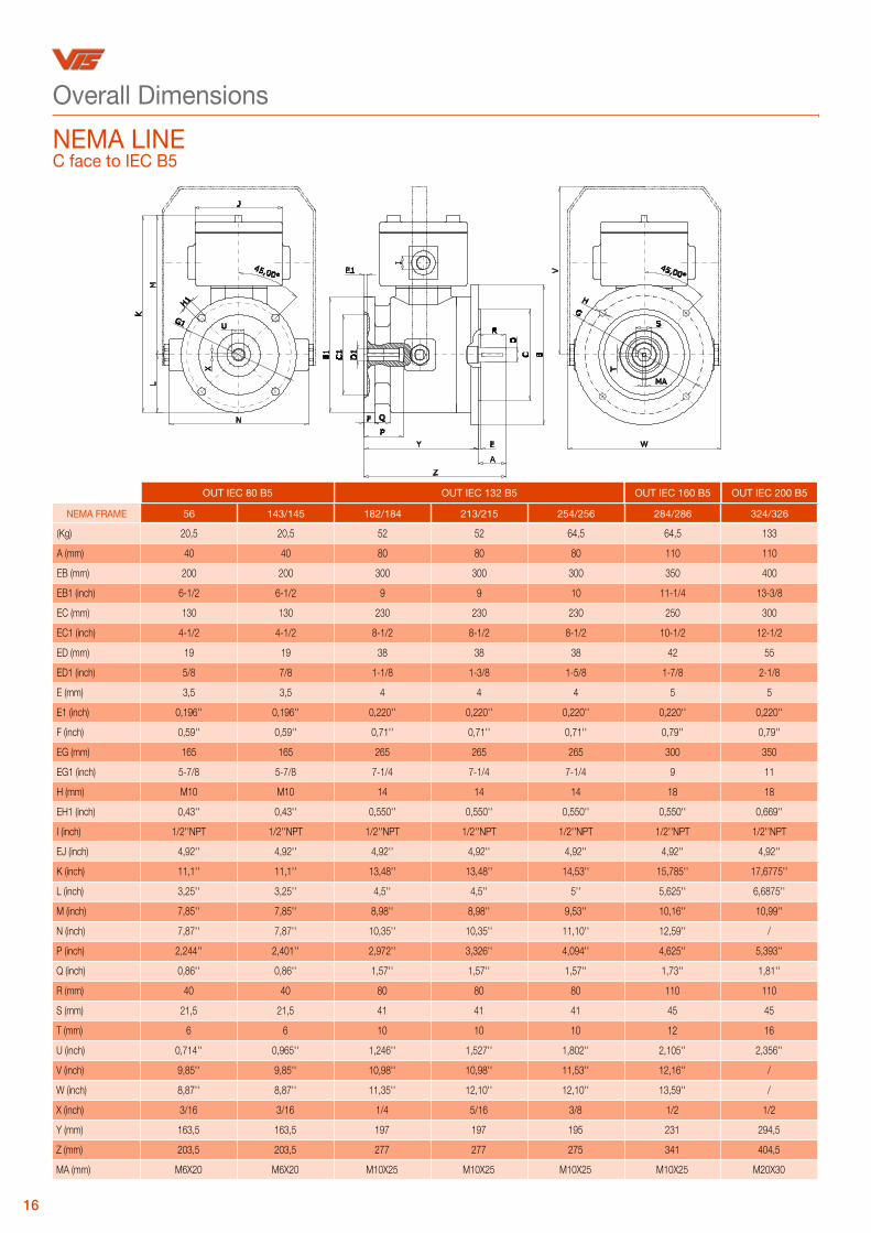
Overall Dimensions
NEMA FRAME 56 143/145 182/184 213/215 254/256 284/286 324/326
(Kg) 20,5 20,5 52 52 64,5 64,5 133
A (mm) 40 40 80 80 80 110 110
EB (mm) 200 200 300 300 300 350 400
EB1 (inch) 6-1/2 6-1/2 9 9 10 11-1/4 13-3/8
EC (mm) 130 130 230 230 230 250 300
EC1 (inch) 4-1/2 4-1/2 8-1/2 8-1/2 8-1/2 10-1/2 12-1/2
ED (mm) 19 19 38 38 38 42 55
ED1 (inch) 5/8 7/8 1-1/8 1-3/8 1-5/8 1-7/8 2-1/8
E (mm) 3,5 3,5 4 4 4 5 5
E1 (inch) 0,196'' 0,196'' 0,220'' 0,220'' 0,220'' 0,220'' 0,220''
F (inch) 0,59'' 0,59'' 0,71'' 0,71'' 0,71'' 0,79'' 0,79''
EG (mm) 165 165 265 265 265 300 350
EG1 (inch) 5-7/8 5-7/8 7-1/4 7-1/4 7-1/4 9 11
H (mm) M10 M10 14 14 14 18 18
EH1 (inch) 0,43'' 0,43'' 0,550'' 0,550'' 0,550'' 0,550'' 0,669''
I (inch) 1/2''NPT 1/2''NPT 1/2''NPT 1/2''NPT 1/2''NPT 1/2''NPT 1/2''NPT
EJ (inch) 4,92'' 4,92'' 4,92'' 4,92'' 4,92'' 4,92'' 4,92''
K (inch) 11,1'' 11,1'' 13,48'' 13,48'' 14,53'' 15,785'' 17,6775''
L (inch) 3,25'' 3,25'' 4,5'' 4,5'' 5'' 5,625'' 6,6875''
M (inch) 7,85'' 7,85'' 8,98'' 8,98'' 9,53'' 10,16'' 10,99''
N (inch) 7,87'' 7,87'' 10,35'' 10,35'' 11,10'' 12,59'' /
P (inch) 2,244'' 2,401'' 2,972'' 3,326'' 4,094'' 4,625'' 5,393''
Q (inch) 0,86'' 0,86'' 1,57'' 1,57'' 1,57'' 1,73'' 1,81''
R (mm) 40 40 80 80 80 110 110
S (mm) 21,5 21,5 41 41 41 45 45
T (mm) 6 6 10 10 10 12 16
U (inch) 0,714'' 0,965'' 1,246'' 1,527'' 1,802'' 2,105'' 2,356''
V (inch) 9,85'' 9,85'' 10,98'' 10,98'' 11,53'' 12,16'' /
W (inch) 8,87'' 8,87'' 11,35'' 12,10'' 12,10'' 13,59'' /
X (inch) 3/16 3/16 1/4 5/16 3/8 1/2 1/2
Y (mm) 163,5 163,5 197 197 195 231 294,5
Z (mm) 203,5 203,5 277 277 275 341 404,5
MA (mm) M6X20 M6X20 M10X25 M10X25 M10X25 M10X25 M20X30
OUT IEC 80 B5 OUT IEC 160 B5 OUT IEC 200 B5OUT IEC 132 B5
16
NEMA LINEC face to IEC B5

Overall Dimensions
COMPACT LINE
TYPE 25 150 350 750
(Kg) 23 32 64 175
EA(+/-1) 178 245 330 425
EB 130 180 258 335
EC 110 160 240 300
ED (E6) 22 max 35 max 70 max 80 max
E 2 1 1 1
F 78 96 106 120
G 12 13 15 18
H 26 36 41 60
I 210 302 350 425
I1 190 282 330 405
EJ 110 110 110 110
K 16 34 41 63
L 181 226 249 286
L1 241 286 309 346
EM 160 225 305 395
EN n°6x6,5 n°6x8,5 n°6x10,5 n°8x12,5
O 126 149 159 184
EP 160 250 305 380
Q 6 10 20 22
R 24,8 38,3 74,9 85,4
S 1XM20 1XM20 1XM20 1XM20
17
30,00°
ØCØBØA E
ØD
I F
G H
L
L1
ØJ K
ØMØN
O
ØP
Q
R
I1S

18
TYPE E14 D-E18 D-E216
(Kg) 20 52 249
EA(+/-1) 300 400 550
EC 230 300 450
ED (E6) 50 65 80
E 6 8 8
E1 5 6 6
F 106 148 153
G 17 21 25
H 44 46 42
I 339 399 400
EJ 125 125 125
K 72 115 115
L 267 280 328
EM 265 350 500
EN 14,5 18 18
O 259 319 320
EP 300 335 347
Q 14 18 22
R 53,8 69,4 85,4
S M20 M20 M20
Overall Dimensions
COMPACT LINE

Brake motors
Flameproof brakes
Flameproof limit switches
Flameproof pendant control stations
Hoist drives
COEL offers a wide range of exclusive products focused on dedicated industrial sectors.
Explore COEL INDUSTRIAL SOLUTIONS on
www.coel-is.com
Coel Industrial Solutions

the most comprehensive range of flameproof brakesavailable on the market
a product of Coel Motori
Via Campania 36/40 - Fizzonasco di Pieve EmanueleMilano - Italy
Tel +39 02 90420039 Fax +39 02 90420747
www.coel-is.com