


Your subscription is active and current. industry. To start … technologies and bands with its...
32
Please look at the mailing label below and read the code in the red box. Code=A: You are receiving the complimentary issue due to your involvement in the industry. To start your free subscription today, please go to www.AntennasOnline.com and subscribe. Code=B: Your subscription is about to expire. Go to www.AntennasOnline.com and renew your subscription today. Code=C: Your subscription is active and current.
Transcript of Your subscription is active and current. industry. To start … technologies and bands with its...
Please look at the m
ailing label below and read the code in the red box.
Code=A
: You are receiving the complim
entary issue due to your involvement in the
industry. To start your free subscription today, please go to w
ww
.AntennasO
nline.com and subscribe.
Code=B
: Your subscription is about to expire. Go to w
ww
.AntennasO
nline.com
and renew your subscription today.
Code=C
: Your subscription is active and current.
CONTENTS
www.ANTENNASONliNE.COm
SPRiNG 2011www.AntennasOnline.com
Volume 14 / Issue 1
Editor & PublisherDavid Webster
Director of ContentShannon Given
Associate EditorsHeather Krier
Nick Depperschmidt
Director of SalesJessi Albers
News EditorsLaura Mayo, Sue Hannebrink, Jeremy Fleming, Jessi Albers
Manager of AdministrationMarsha Grillo
Director of Support ServicesMarc Vang
Circulation/Data EntryRoss Webster
Office ManagerJulie Williams
Advertising Sales and MarketingLaura Mayo, Account Executive
Julie Hammond, Production ManagerJennifer Graham, Marketing Assistant
ANTENNA SYSTEMS & TECHNOLOGY (ISSN #1092-2553) is a publication of
Webcom Communications Corp.
Subscriptions for one year (bi-monthly) are free to qualified recipients in the U.S., $44 for non qualified U.S. and $60 outside the U.S. Single copies are $20 each plus shipping. Back issues are available. Payment must be made in US funds in order to process the or-der. Direct all subscription inquiries, orders and address changes to Fulfillment Services.
© Copyright 2011 Webcom Communications Corp. Material in this publication may not be reproduced in any form without written per-mission. Requests for permission should be directed to the customer service manager.
Reprints: For reprint requests contact Web-com Communications at 720-528-3770.
Webcom Communications Corp.7355 E. Orchard Road, Ste. 100Greenwood Village, CO 80111
Phone 720-528-3770Fax 720-528-3771
fEATuRES Advanced MIMO Over-the-Air Testing Methodology to Test True
Device Performance . . . . . . . . . . . . . . . . . . . . . . . . . . . . . . . . . . . . . . . . . . . . . . . . 6
MIMO Antennas for 802.11n Based WLAN System. . . . . . . . . . . . . . . . . . . . . . .11
Where Functionality Takes Flight: Tunable Antennas and the Future of
Wireless Networks and Device Performance. . . . . . . . . . . . . . . . . . . . . . . . . . . 13
PROduCTS & SERviCESEditor’s Choice . . . . . . . . . . . . . . . . . 4
Antennas . . . . . . . . . . . . . . . . . . . . . 15
Components . . . . . . . . . . . . . . . . . . 21
Materials . . . . . . . . . . . . . . . . . . . . . .23
Test & Measurement. . . . . . . . . . . .24
WiMAX/Wi-Fi/LTE. . . . . . . . . . . . . . 25
dEPARTmENTSIndustry News . . . . . . . . . . . . . . . . .26
Marketplace. . . . . . . . . . . . . . . . . . . 29
Advertising Index . . . . . . . . . . . . . .29
Research & Development. . . . . . .30
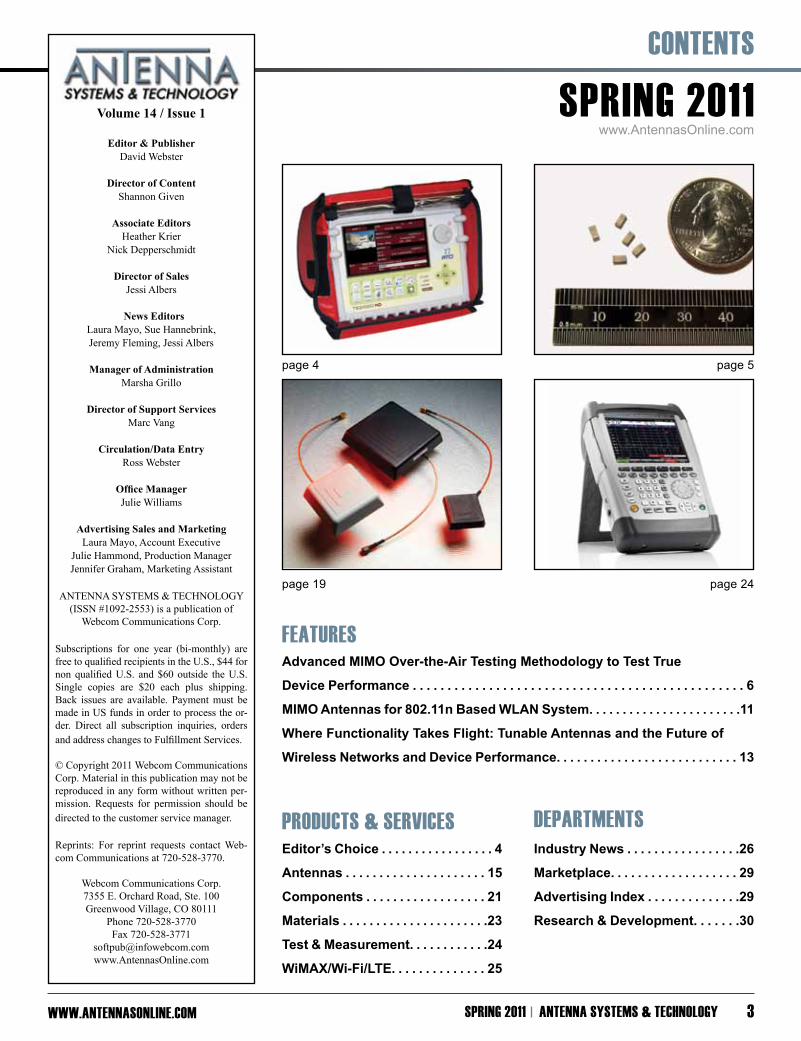
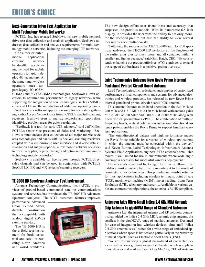
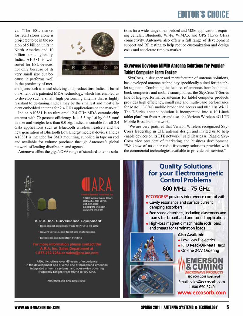
page 4 page 5
page 19 page 24
SPRiNG 2011 ANTENNA SySTEmS & TEChNOlOGy 3
EdiTOR’S ChOiCE
www.ANTENNASONliNE.COmANTENNA SySTEmS & TEChNOlOGy SPRiNG 20114
Next-Generation drive Test Application for multi-Technology mobile Networks
PCTEL, Inc. has released SeeHawk, its new mobile network drive test data collection and analysis application. SeeHawk ad-dresses data collection and analysis requirements for multi-tech-nology mobile networks, including the emerging LTE networks. Consumer-oriented, mobile applications consume network bandwidth, accelerat-ing the need for mobile operators to rapidly de-ploy 4G technology. At the same time, wireless operators must sup-port legacy 2G (GSM, CDMA) and 3G (WCDMA) technologies. SeeHawk allows op-erators to optimize the performance of legacy networks while supporting the integration of new technologies, such as MIMO-enhanced LTE and the introduction of additional operating bands. SeeHawk is a software application suite for accurately gather-ing Radio Access Network data from PCTEL’s SeeGull scanning receivers. It allows users to analyze networks and report data, identifying problem areas for quick resolution. “SeeHawk is a tool for early LTE adopters,” said Jeff Miller, PCTEL’s senior vice president of Sales and Marketing. “See-Hawk’s simultaneous data collection of all major mobile wide area technologies and bands with its SeeGull scanning receivers, coupled with a customizable user interface and diverse data vi-sualization and analysis options, allow mobile network operators to effectively plan, deploy, manage and optimize evolving multi-technology mobile networks.” SeeHawk is available for license now through PCTEL direct sales channels and can be used in conjunction with PCTEL’s SeeGull LX, EX and MX series of scanning receivers.
TE-2000 hd Spectrum Analyzer Test instrumentAntenna Technology Communications, Inc. (ATCi), a pro-
vider of ground-based commercial satellite communications systems and services, has introduced the TE-2000 HD Advanced Spectrum Analyzer. The ATCi instrument features improved performance, advanced Color TV/SAT Meter, durable construction that is compatible with analog, digital (DVB) satellite standard. The TE-2000 HD is the a field test instru-ment for both terres-trial and satellite cov-ering North America and world standards.
The new design offers user friendliness and accuracy that surpasses the previous models. With its panoramic 6.5-inch display, it provides the user with the ability to not only moni-tor the decoded picture but also the ability to view several measurements simultaneously. “Following the success of the ATCi TE-900 and TE-1200 spec-trum analyzers, the TE-2000 HD performs all the functions of the earlier units plus so much more, and all contained within a smaller and lighter package,” said Gary Hatch, CEO. “By consis-tently enhancing our product offerings, ATCi continues to expand the scope of our business in a positive, productive way.”
laird Technologies Releases New Revie Prime internal Pentaband Printed Circuit Board Antenna Laird Technologies, Inc., a designer and supplier of customized performance-critical components and systems for advanced elec-tronics and wireless products, has released its new Revie Prime internal pentaband printed circuit board (PCB) antenna. This antenna features multi-band operation in the 824 MHz to 960 MHz and 1,710 MHz to 2,170 MHz bands with antenna gains of 2.20 dBi at 900 MHz and 3.80 dBi at 2,000 MHz, along with linear vertical polarization (VPOL). The combination of multiple frequency bands, vertical polarization and an omnidirectional an-tenna pattern enables the Revie Prime to support limitless wire-less applications. “The omnidirectional pattern and high performance makes the Revie Prime suitable for a variety of wireless applications in which the antenna must be concealed within the device,” said Kevin Burton, Laird Technologies Infrastructure Antenna Systems Field Applications engineer. “The antenna’s small size makes it well suited for use in environments where wide angle coverage is necessary for successful wireless deployment.” The antenna’s small and lightweight form factor allows it be hidden almost anywhere by directly mounting it to the inside of non-metallic device housings. This provides an invisible solution for most applications including wireless terminals, point of sale (POS), machine-to-machine (M2M), meter reading, Long Term Evolution (LTE), telemetry and security. Available in various ca-ble and connector configurations, the antenna is RoHS compliant.
Antenova Adds ultra-Small indica 2.4 Ghz mdA Ceramic Chip Antenna to gigaNOvA Range of Standard Antennas Antenova Ltd, the integrated antenna and RF solutions compa-ny, has added the Indica 2.4 GHz MDA ceramic chip antenna, the smallest in the gigaNOVA range of standard antennas. Designed for ease of integration into wireless devices, ultra-small Indica 2.4 GHz antenna is well suited for a wide range of embedded ap-plications where space is limited and particularly in the proximity of metal objects, such as Electronic Shelf Labels (ESL). “We are experiencing a global mega-trend of connected de-vices, with an ever growing range of embedded wireless applica-tions, devices and markets,” said Greg McCray, CEO of Anteno-
EdiTOR’S ChOiCE
www.ANTENNASONliNE.COm SPRiNG 2011 ANTENNA SySTEmS & TEChNOlOGy 5
ISO 9001:2008 Registered
Email: [email protected]
www.eccosorb.com
Also Available: • Low Loss Dielectrics • RFID Read-On-Metal Tags • On-line 24/7 Ordering
ECCOSORB® provides interference control with:
• Cavity resonance and surface current damping absorbers
• Free space absorbers, including elastomers and foams for broadband and tuned applications
• High-loss magnetic machinable rods, bars and sheets for termination loads
600 MHz - 75 GHz
Quality Solutions for your Electromagnetic
Control Problems
va. “The ESL market for retail stores alone is projected to be in the re-gion of 5 billion units in North America and 10 billion units globally. Indica A10381 is well suited for ESL devices, not only because of its very small size but be-cause it performs well in the proximity of met-al objects such as metal shelving and product tins. Indica is based on Antenova’s patented MDA technology, which has enabled us to develop such a small, high performing antenna that is highly resistant to de-tuning. Indica may be the smallest and most effi-cient embedded antenna for 2.4 GHz applications on the market.” Indica A10381 is an ultra-small 2.4 GHz MDA ceramic chip antenna with 70 percent efficiency. It is 3.3 by 1.6 by 0.65 mm³ in size and weighs less than 0.016g. Indica is suitable for all 2.4 GHz applications such as Bluetooth wireless headsets and the new generation of Bluetooth Low Energy medical devices. Indica A10381 is intended for SMD mounting, supplied in tape on reel and available for volume purchase through Antenova’s global network of leading distributors and agents. Antenova offers the gigaNOVA range of standard antenna solu-
tions for a wide range of embedded and M2M applications requir-ing cellular, Bluetooth, Wi-Fi, WiMAX and GPS (1.575 GHz) connectivity. Antenova also offers a full range of development support and RF testing to help reduce customization and design costs and accelerate time-to-market.
Skycross develops mimiO Antenna Solutions for Popular Tablet Computer form factor SkyCross, a designer and manufacturer of antenna solutions, has developed antenna technology specifically suited for the tab-let segment. Combining the features of antennas from both note-book computers and mobile smartphones, the SkyCross T-Series line of high-performance antennas for tablet computer products provides high efficiency, small size and multi-band performance for MIMO 3G/4G mobile broadband access and 802.11n Wi-Fi. The T-Series antenna solution is incorporated into a 10.1-inch tablet platform from Acer and uses the Verizon Wireless 4G LTE Mobile Broadband network. “We are very gratified that Verizon Wireless recognized Sky-Cross leadership in LTE antenna design and invited us to help enable devices on its LTE network,” said Charles A. Riggle, Sky-Cross vice president of marketing and business development. “We know of no other radio-frequency solutions provider with the commercial technologies available to provide this service.”

fEATuRE ARTiClE
www.ANTENNASONliNE.COmANTENNA SySTEmS & TEChNOlOGy SPRiNG 20116
With the recent deployments of live LTE networks and ongoing WiMAX deploy-ments worldwide, today’s new mobile
devices are required to deliver higher levels of throughput than ever before. Multiple Input, Multiple Output (MIMO) technol-ogy is used as the foundation of 4G radio technologies including LTE and WiMAX to enhance the overall performance of radio transmitters and receivers with respect to the effects of the air interface. Multiple transmit and receive data paths are used in MIMO systems to provide significant increases in throughput and robustness by exploiting the characteristics of the radio channel. As a result, MIMO system performance is directly related to the propagation environment in which the device is operating. In developing the devices and systems that will support these rapidly growing 4G networks, over-the-air (OTA) testing may provide the most effective method for measuring the performance of MIMO algorithms, as these algorithms are strongly influenced by the propagation environment and critically affected by the de-sign of the device’s antennas and antenna placement. MIMO OTA can be used to verify the performance of an entirely integrated product, including the antennas, which is a different approach than many commonly-used conducted test methodologies that remove the antenna from the test equation by connecting radio transmitters and radio receivers using RF cables and connectors. Conducted testing offers highly controlled and repeatable testing, but often lacks the real world dynamic conditions that are intro-duced when signals are transmitted OTA. Therefore, OTA testing that creates an environment where signals are transmitted physi-cally “over the air” enables capture of the effects of the overall device’s design, including antenna design/placement, in a suite of performance measurements. An effective MIMO OTA test solution must be able to provide a comparable and efficient test platform for testing devices to al-low effective benchmarking and to ultimately allow the tester to deliver an accurate good/bad prediction of performance without leaving the controlled conditions of the lab. This article will ex-plore how a new solution for MIMO OTA testing that combines the use of channel emulators that use propagation models to rec-reate the dynamic over the air conditions typical in mobile wire-less conditions with a reverberation chamber, an environment for testing electromagnetic compatibility and other electromagnetic investigations, could be the most balanced and cost effective ap-proach to achieving repeatability while producing realistic per-formance results.
Applying mimO Over-the-Air Testing for device Performance measurements
Testing the overall device as it would normally operate is the best way to understand true performance as experienced by the
user. This means testing the entire device in an active operational state, with the actual interaction of the antennas, RF front ends and baseband processing elements. Operational environments of the device, such as indoor, outdoor, rural, urban, nomadic, mobile or highly mobile become a basic set for which the device must be tested. Furthermore, the antennas within the mobile device would, ideally, be totally efficient and fully independent of each other but today’s preference for reduced size and greater com-plexity make this increasingly difficult. This, along with many other factors such as the need to support multiple bands and mul-tiple technologies with a limited number of antennas and power restrictions, has an impact on MIMO performance. Thus, MIMO makes testing the entire device, including antennas, more impor-tant than ever before. Spatial diversity gain is extremely difficult to predict without physically measuring the OTA performance of the complete device. It also useful to test the device with a performance metric or figure of merit (FOM) that is consistent with user operation and experience, thus providing a real world metric. As MIMO devices are defined to provide enhanced throughput, data throughput be-comes a very real FOM - in fact, industry groups such as 3GPP, COST2100, and CTIA have recommended that data throughput be the preferred FOM for MIMO OTA testing. Other tests such as TIS (total isotropic sensitivity) and TRP (total radiated power) are also being considered as supplementary FOMs to evaluate a MIMO device.
Summary of Proposed mimO OTA methods One of the biggest challenges of MIMO OTA testing to date is getting repeatable measurements independent of location. Sev-eral candidates for MIMO OTA methods have emerged from the work of 3GPP RAN4 and COST2100. Although there are vari-ants of each, reverberation chambers and anechoic chambers gen-erally comprise the main solutions. The anechoic chamber solution utilizes a controlled environ-ment to dissipate as much wave energy as possible before reflect-ing it away, creating a reference environment with a controlled “quiet zone” that removes all signal channel variables. The an-echoic chamber systematically eliminates multipath reflections, but in order to test MIMO, the effects of multipath must be added back to the measurement system by implementing a new kind of reference environment. The reverberation chamber method takes the opposite approach in creating an OTA test environment. [1] The reverberation cham-ber is a highly reflective environment where multipath signals fill the chamber with standing waves, which are mechanically stirred to expose the device under test (DUT) to a full distribution of this highly variable propagation environment. By getting many samples, the statistical response of the DUT to this controlled
Advanced mimO Over-the-Air Testing methodology to Test True device PerformanceBy George Reed, Vice President of Marketing and Product Management • Azimuth Systems
fEATuRE ARTiClE
www.ANTENNASONliNE.COm SPRiNG 2011 ANTENNA SySTEmS & TEChNOlOGy 7
reflective environment can be accurately characterized. With ac-curate calibration of the chamber, a reference environment can be created that is highly repeatable and encompasses the conditions that are challenging to the designers of today’s high performance wireless devices.
Testing performed by NTT DOCOMO [2] found that good re-peatability was achieved by using a reverberation chamber meth-odology, a simplified anechoic chamber methodology, and an advanced anechoic chamber methodology. It also clarified that a good MIMO antenna design can adequately be differentiated from a bad MIMO antenna design through MIMO OTA testing with ad-equate repeatability. The results further illustrate that the reverber-ation chamber methodology has an advantage of very short testing time with the same level of repeatability as the anechoic chamber methods. A summary of the findings indicate that results can be obtained with the reverberation chamber methodology eight times faster than the anechoic chamber methodology, under the assump-tion that the OTA throughput is measured every 45°.
Channel Emulator and Reverberation Chamber Combination: A New mimO OTA Test method
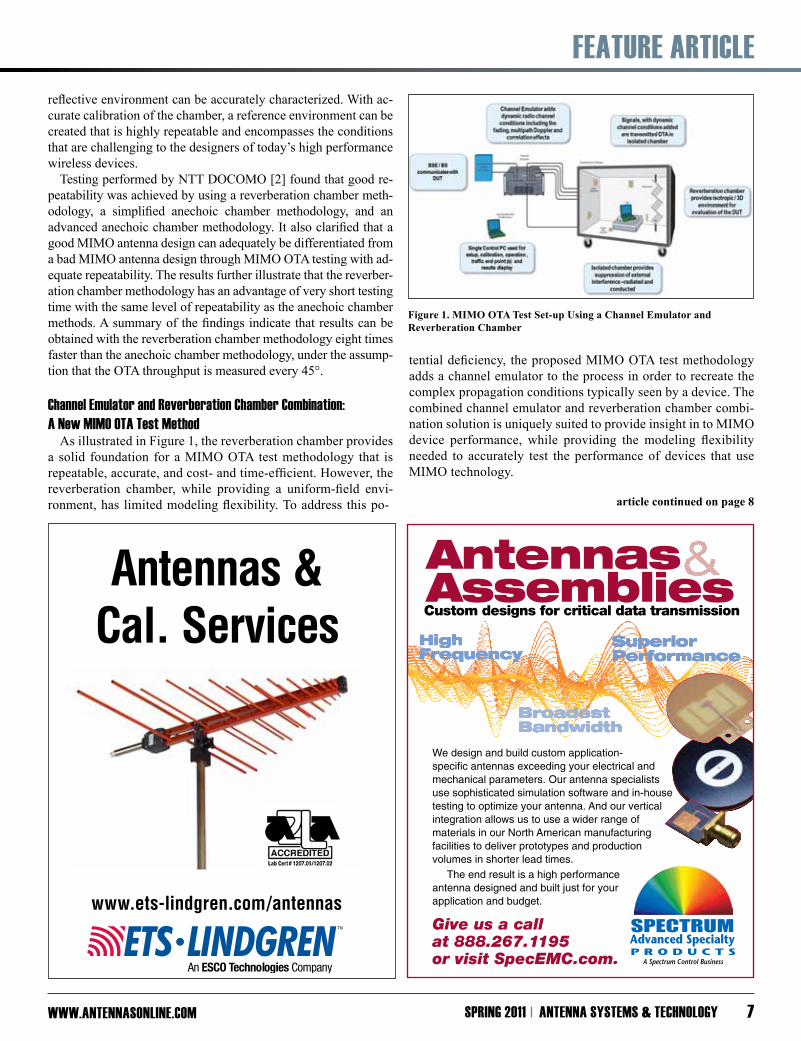
As illustrated in Figure 1, the reverberation chamber provides a solid foundation for a MIMO OTA test methodology that is repeatable, accurate, and cost- and time-efficient. However, the reverberation chamber, while providing a uniform-field envi-ronment, has limited modeling flexibility. To address this po-
tential deficiency, the proposed MIMO OTA test methodology adds a channel emulator to the process in order to recreate the complex propagation conditions typically seen by a device. The combined channel emulator and reverberation chamber combi-nation solution is uniquely suited to provide insight in to MIMO device performance, while providing the modeling flexibility needed to accurately test the performance of devices that use MIMO technology.
www.ets-lindgren.com/antennas
Antennas &Cal. Services
Antennas AssembliesCustom designs for critical data transmission
We design and build custom application-specific antennas exceeding your electrical and mechanical parameters. Our antenna specialists use sophisticated simulation software and in-house testing to optimize your antenna. And our vertical integration allows us to use a wider range of materials in our North American manufacturing facilities to deliver prototypes and production volumes in shorter lead times.
The end result is a high performance antenna designed and built just for your application and budget.
Give us a call at 888.267.1195 or visit SpecEMC.com.
1084 AntennaAd-AntSysTech_Layout 6 1/10/11 10:01 AM Page 1
Figure 1. MIMO OTA Test Set-up Using a Channel Emulator and Reverberation Chamber
article continued on page 8
fEATuRE ARTiClE
www.ANTENNASONliNE.COmANTENNA SySTEmS & TEChNOlOGy SPRiNG 20118
A channel emulator cascaded with a reverberation chamber, as shown in Figure 1, gives many degrees of freedom for creating specific channel conditions and producing FOM results useful in MIMO OTA test. The channel conditions that will be discussed with resultant behavior include multipath or power delay profile, Doppler spectrum and MIMO correlation.
Power delay ProfileThe scattering of EM waves within a reverberation chamber
creates a Rayleigh distributed signal amplitude at a receiver. The reverberation can be damped or loaded to create a PDP or multipath delay with various decay times using, for example, blocks of RF absorber material, a phantom head or a tank filled with liquid.
This use of a reverberation chamber alone creates a dense exponentially decaying PDP with an rms delay spread that is a function of the chamber loading. [3] Although this may be ap-propriate for a single cluster model, it is not representative of the typical multicluster or outdoor urban models. Standard channel models as defined by 3GPP for LTE testing [1] typically have many discrete multipath environments with greatly delayed mul-tipath components. Using the channel emulator and reverberation chamber solution, PDPs to support both indoor and outdoor envi-ronments can be accurately created.
A DUT is placed in the reverberation chamber and exposed to the multipath components arriving from many, generally un-controlled, angles of incidence. When the device response is averaged over all paddle positions, a so-called uniform spatial channel is created. The uniform channel provides a useful model for many applications and creates an overall 3-D isotropic envi-ronment. As most MIMO devices are intended to operate in all orientations and not just an azimuth plane, this environment is very helpful in understanding real-world performance.
A channel emulator is placed in the signal path of the rever-
beration chamber to produce a cascaded response. The channel emulator can be configured with multiple taps with fixed weights αk and excess delays τk to create a specific impulse response:
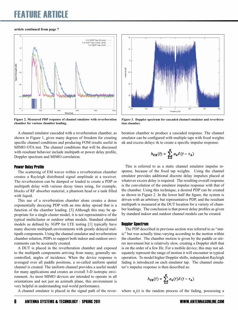
This is referred to as a static channel emulator impulse re-sponse, because of the fixed tap weights. Using the channel emulator provides additional discrete delay impulses placed at whatever excess delay is required. The resulting overall response is the convolution of the emulator impulse response with that of the chamber. Using this technique, a desired PDP can be created as shown in Figure 2. In the lower half the figure, the system is driven with an arbitrary but representative PDP, and the resultant multipath is measured at the DUT location for a variety of cham-ber loadings. The conclusion is that power delay profiles as given by standard indoor and outdoor channel models can be created.
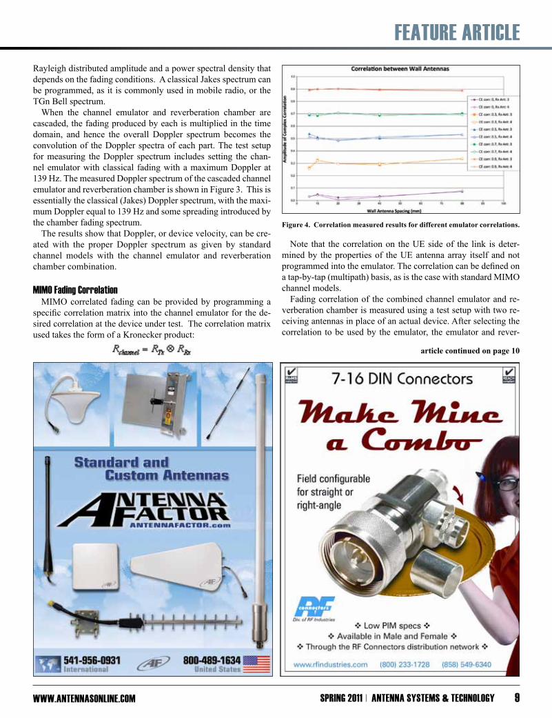
doppler Spectrum The PDP described in previous section was referred to as “stat-ic” but was actually time-varying according to the motion within the chamber. The chamber motion is given by the paddle or stir-rer movement but is relatively slow, creating a Doppler shift that is on the order of a few Hz. For a mobile device, this may not ad-equately represent the range of motion it will encounter in typical operation. To model higher Doppler shifts, independent Rayleigh fading is introduced on each emulator tap. The channel emula-tor’s impulse response is then described as:
where αk(t) is the random process of the fading, possessing a
Figure 2. Measured PDP response of channel emulator with reverberation chamber for various chamber loading.
Figure 3. Doppler spectrum for cascaded channel emulator and reverbera-tion chamber.
article continued from page 7
fEATuRE ARTiClE
www.ANTENNASONliNE.COm SPRiNG 2011 ANTENNA SySTEmS & TEChNOlOGy 9
Rayleigh distributed amplitude and a power spectral density that depends on the fading conditions. A classical Jakes spectrum can be programmed, as it is commonly used in mobile radio, or the TGn Bell spectrum.
When the channel emulator and reverberation chamber are cascaded, the fading produced by each is multiplied in the time domain, and hence the overall Doppler spectrum becomes the convolution of the Doppler spectra of each part. The test setup for measuring the Doppler spectrum includes setting the chan-nel emulator with classical fading with a maximum Doppler at 139 Hz. The measured Doppler spectrum of the cascaded channel emulator and reverberation chamber is shown in Figure 3. This is essentially the classical (Jakes) Doppler spectrum, with the maxi-mum Doppler equal to 139 Hz and some spreading introduced by the chamber fading spectrum. The results show that Doppler, or device velocity, can be cre-ated with the proper Doppler spectrum as given by standard channel models with the channel emulator and reverberation chamber combination.
mimO fading CorrelationMIMO correlated fading can be provided by programming a
specific correlation matrix into the channel emulator for the de-sired correlation at the device under test. The correlation matrix used takes the form of a Kronecker product:
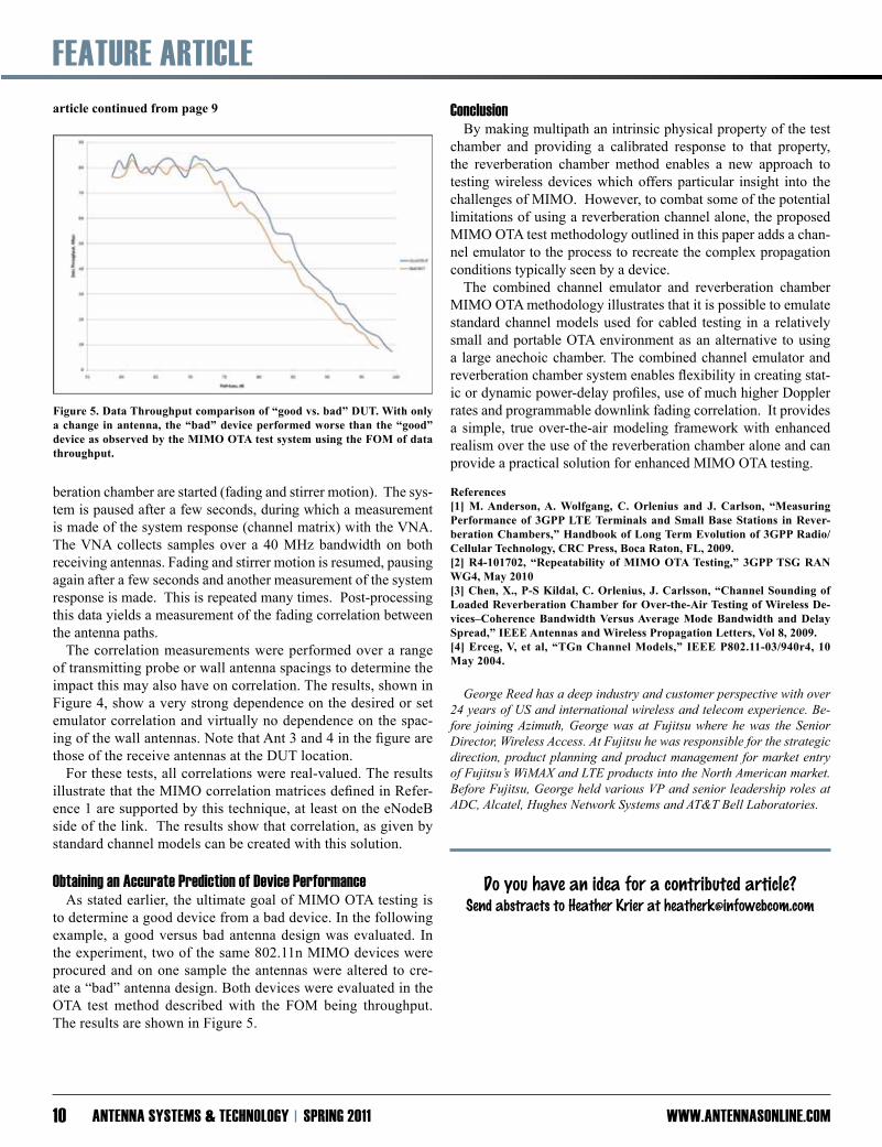
Note that the correlation on the UE side of the link is deter-mined by the properties of the UE antenna array itself and not programmed into the emulator. The correlation can be defined on a tap-by-tap (multipath) basis, as is the case with standard MIMO channel models. Fading correlation of the combined channel emulator and re-verberation chamber is measured using a test setup with two re-ceiving antennas in place of an actual device. After selecting the correlation to be used by the emulator, the emulator and rever-
Figure 4. Correlation measured results for different emulator correlations.
article continued on page 10
fEATuRE ARTiClE
www.ANTENNASONliNE.COmANTENNA SySTEmS & TEChNOlOGy SPRiNG 201110
beration chamber are started (fading and stirrer motion). The sys-tem is paused after a few seconds, during which a measurement is made of the system response (channel matrix) with the VNA. The VNA collects samples over a 40 MHz bandwidth on both receiving antennas. Fading and stirrer motion is resumed, pausing again after a few seconds and another measurement of the system response is made. This is repeated many times. Post-processing this data yields a measurement of the fading correlation between the antenna paths.
The correlation measurements were performed over a range of transmitting probe or wall antenna spacings to determine the impact this may also have on correlation. The results, shown in Figure 4, show a very strong dependence on the desired or set emulator correlation and virtually no dependence on the spac-ing of the wall antennas. Note that Ant 3 and 4 in the figure are those of the receive antennas at the DUT location. For these tests, all correlations were real-valued. The results illustrate that the MIMO correlation matrices defined in Refer-ence 1 are supported by this technique, at least on the eNodeB side of the link. The results show that correlation, as given by standard channel models can be created with this solution.
Obtaining an Accurate Prediction of device PerformanceAs stated earlier, the ultimate goal of MIMO OTA testing is
to determine a good device from a bad device. In the following example, a good versus bad antenna design was evaluated. In the experiment, two of the same 802.11n MIMO devices were procured and on one sample the antennas were altered to cre-ate a “bad” antenna design. Both devices were evaluated in the OTA test method described with the FOM being throughput. The results are shown in Figure 5.
Conclusion By making multipath an intrinsic physical property of the test chamber and providing a calibrated response to that property, the reverberation chamber method enables a new approach to testing wireless devices which offers particular insight into the challenges of MIMO. However, to combat some of the potential limitations of using a reverberation channel alone, the proposed MIMO OTA test methodology outlined in this paper adds a chan-nel emulator to the process to recreate the complex propagation conditions typically seen by a device. The combined channel emulator and reverberation chamber MIMO OTA methodology illustrates that it is possible to emulate standard channel models used for cabled testing in a relatively small and portable OTA environment as an alternative to using a large anechoic chamber. The combined channel emulator and reverberation chamber system enables flexibility in creating stat-ic or dynamic power-delay profiles, use of much higher Doppler rates and programmable downlink fading correlation. It provides a simple, true over-the-air modeling framework with enhanced realism over the use of the reverberation chamber alone and can provide a practical solution for enhanced MIMO OTA testing.
References[1] M. Anderson, A. Wolfgang, C. Orlenius and J. Carlson, “Measuring Performance of 3GPP LTE Terminals and Small Base Stations in Rever-beration Chambers,” Handbook of Long Term Evolution of 3GPP Radio/Cellular Technology, CRC Press, Boca Raton, FL, 2009.[2] R4-101702, “Repeatability of MIMO OTA Testing,” 3GPP TSG RAN WG4, May 2010[3] Chen, X., P-S Kildal, C. Orlenius, J. Carlsson, “Channel Sounding of Loaded Reverberation Chamber for Over-the-Air Testing of Wireless De-vices–Coherence Bandwidth Versus Average Mode Bandwidth and Delay Spread,” IEEE Antennas and Wireless Propagation Letters, Vol 8, 2009.[4] Erceg, V, et al, “TGn Channel Models,” IEEE P802.11-03/940r4, 10 May 2004.
GeorgeReedhasadeepindustryandcustomerperspectivewithover24yearsofUSandinternationalwirelessandtelecomexperience.Be-fore joiningAzimuth,GeorgewasatFujitsuwherehewas theSeniorDirector,WirelessAccess.AtFujitsuhewasresponsibleforthestrategicdirection,productplanningandproductmanagementformarketentryofFujitsu’sWiMAXandLTEproductsintotheNorthAmericanmarket.BeforeFujitsu,GeorgeheldvariousVPandseniorleadershiprolesatADC,Alcatel,HughesNetworkSystemsandAT&TBellLaboratories.
Figure 5. Data Throughput comparison of “good vs. bad” DUT. With only a change in antenna, the “bad” device performed worse than the “good” device as observed by the MIMO OTA test system using the FOM of data throughput.
article continued from page 9
Do you have an idea for a contributed article?
Send abstracts to Heather Krier at [email protected]
fEATuRE ARTiClE
www.ANTENNASONliNE.COm SPRiNG 2011 ANTENNA SySTEmS & TEChNOlOGy 11
RPM PSI ®
8750 Shirley Ave., Northridge, CA 91324-3409
Phone: +1 818 349 8680 | Fax: +1 818 772 7577 | [email protected]
RPM PSI
8750 Shirley Ave., Northridge, CA 91324-34098750 Shirley Ave., Northridge, CA 91324-3409
Rotating Precision Mechanisms Inc.
¥ Integration Of Antennas, Sensors, Optics, Rotary Joints, Waveguide, Slip Rings, and other Ancillary
Components
¥ In- House ¥ Engineering¥ Manufacturing¥ Rigorous Testing
¥ RPM has developed over 500 COTS & NDI designs from One to Six Axis, including Controls
ANTENNA POSITIONERS
SeriesPG-1500
SeriesPG-0500
SeriesPG-5000
¥ Integration Of Antennas,
The System IntegratorÕsChoice For Best Value and Timely
Solutions!
other Ancillary
SeriesPG-5000
SeriesPG-1500
SeriesPG-0500
W W W . R P M - P S I . C O M
Over past two to three years there has been a significant surge in real time, low latency video and data applications over wireless networks. These applications drive large amounts of data over both cellular and wireless local area network (LAN) based enterprise networks.
The implementation of wireless LANs by enterprises across various vertical industries seeking to support a grow-ing mobile workforce with voice, data and video accessibility has increased the need for network speed, capacity and re-liability. Research firm ABI reports that the uptake of Wi-Fi within healthcare institutions has grown more than 60 per-cent during the past 12 months in both wireless LAN and Wi-Fi RTLS (real-time locations systems) deployments. Double-digit growth is expected to continue for at least the near term, and the revenue from worldwide sales of Wi-Fi enabled health-care products will reach nearly $5 billion in 2014.[1] Other in-dustries, including education, utilities (smart grids), mass tran-sit and manufacturing, are being affected by similar trends. In addition, the exploding use of multi-media through smart-phone technology in the consumer market is expected to fuel this industry’s growth. A recent release by research firm iSuppli Corp. reports that global smart phone shipments are expected to increase 105 percent from 246.9 million in 2010 to more than 506 million units by 2014.[2] This growth has put tremendous pres-sure on existing cellular networks in terms of capacity. As a result of increasing consumer and business demand for voice and data video streaming capabilities worldwide, IT net-work architects and cellular operators are leveraging 802.11n based wireless LAN networks that utilize Multiple Input, Mul-tiple Output (MIMO) antenna technology to off-load and support the high data rate demand. Conventional 802.11 (a, b or g) networks typically utilize sin-gle input single output (SISO) technology. This technology uti-lizes a single transmitter and a single receiver with either one or two antennas on each side. Networks that use this technology are designed to avoid multipath and line-of-sight obstacles that can create signal nulls and degrade wireless coverage. MIMO technology, on the other hand, uses multiple transmit-ters and receivers. It leverages multipath signals to deliver en-hanced data throughput, range, reliability and spectral efficiency, even in environments that would typically be susceptible to line of sight interference and signal fading. In optimal signal to noise ratio (SNR) conditions, a data stream can also be split between multiple transceivers with independent antennas for transmission allowing for higher data rates.
In MIMO 2x3 Receive Diversity Systems, smart antennas use spatial diversity technology to improve signal-to-noise ratio. For example, if the re-ceiver has more antennas than spatial streams (in a 2x3 system two antennas transmit while three antennas receive) the third antenna can add diversity to the receiver end, improving system robustness through longer distances at given speeds. When multiple spatial streams are used with MIMO (3x3, three transmit antennas and three receive antennas) it is called SDM (spatial division multi-plexing). This method requires advanced signal processing for transmit (Tx) and receive (Rx) streams in order to avoid cross signal interference that can lead to
degraded system performance. Spatial streams require complete
By Rishi Bharadwaj and Ana Bakas, Product Management • PCTEL
mimO Antennas for 802.11n Based wlAN System
article continued on page 12

fEATuRE ARTiClE
www.ANTENNASONliNE.COmANTENNA SySTEmS & TEChNOlOGy SPRiNG 201112
matching Tx/Rx radio links while diversity only systems require a single Rx (receive) radio.
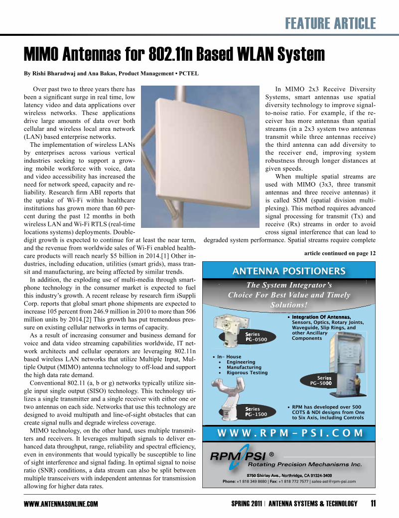
Several of the 802.11n wireless LAN systems that are current-ly being deployed are dual band covering 2.4 GHz and 5 GHz bands. These systems get deployed in a variety of different loca-tions including transportation hubs (airports, train stations), en-tertainment venues (stadiums, concert halls) and office buildings to name a few. Each of these locations present their own set of propagation environment, coverage and antenna installation chal-lenges. Most of these locations are space constrained resulting in requirements for compact antennas. Aesthetics are important, so antennas need to either blend in with the environment or have to be hidden in locations that may not be ideal for radio signal propagation and coverage. Multiple stand alone antennas are commonly used in MIMO systems, but because the spacing and interaction between the an-tenna elements is crucial to achieve optimal throughput rates, sys-tem designers often opt to house multiple antennas into a single radome. This allows them to control the exact spacing between the antenna elements. Since antennas are utilized, among other things, to mitigate multipath, they cannot be designed and their performance can-not be assessed without considering the propagation environ-ment. Antenna installation and placement requirements should be thoroughly understood at the beginning of the design cycle. (For example, will the antenna be wall, mast or ceiling mounted?) Other considerations, including customer size restrictions for the antenna as it relates to cosmetic or practical installation issues are also important, but often overlooked until far too late into the design development cycle. WLAN MIMO antennas typically involve multiple element covering 2.4 GHz and 5 GHz frequencies in a single housing with each element linked to a separate transceiver. A well designed MIMO antenna must provide consistent radiation patterns among spatial streams, stable gain performance across all the operating frequencies, and proper isolation between radiating elements. A key fact to keep in mind is that electrical performance is depen-dent on the size of the antenna. Larger antennas can provide high-er gain and narrower beam widths ideal for deployments where there is a high concentration of data intensive users For example, one can look at a scenario where there is a need to have dual band 802.11n coverage in a large sports arena for offloading voice and video traffic from smart phones. A typical football stadium would require more than 200 access point, with
each access point providing coverage over a
fairly narrow area to limit the number of users and minimize in-terference. Antennas for these access points will need to have nar-row beam widths, about 35° elevation and 55° azimuth. One needs a fairly large antenna housing (about 14 inches by 14 inches) to achieve this beam width and to collocate six antenna elements (3 for 2.4 GHz and 3 for 6 GHz) with ideal port to port isolation. This design would yield a gain of 12 dBi or higher for both frequency bands; however gain may have to be attenuated to meet FCC re-quirements. A well designed antenna would yield fairly consistent patterns across frequency range and among different radiating ele-ments. There may be several scenarios where space is limited and a 14 inch by 14 inch housing may be too large. For these cases, one can consider a smaller 8 inch by 12 inch housing as an exam-ple. This design will face several challenges in meeting the desired specifications as the beam width would be larger, approximately 35° elevation and 90° azimuth at 2.4 GHz. Port to port isolation between elements would suffer and would be about 10 dB lower than the larger antenna. Gain would be lower and patterns would not be as consistent due to reflections caused by the close proxim-ity of other radiating elements. Customer expectations for higher gain in small packages, set by their experience with traditional SISO systems, have forced de-signers to find attractive, less obtrusive ways to implement their MIMO systems. As long as the antenna designer has a full under-standing of the system requirements, various techniques can be utilized to achieve the optimal MIMO antenna design. For example, to address size constraint issues while deliver-ing required spatial stream RF properties, designers can optimize their antenna designs by making fine adjustments to the antenna radome shape or thickness; also, variations in the placement and/or the spacing of the antenna elements within the required foot-print can help a designer achieve targeted azimuth ripple or isola-tion specs, despite the size constraints. Demand for high data rate applications is going to continue to grow and MIMO based 802.11n WiFi systems will play a key role in enabling high throughput wireless access. Good Signal to noise ratio is key to realize the high throughput potential of 802.11n based wireless systems. Antennas play a critical role in providing appropriate coverage and desired signal to noise ratio conditions. It’s important that MIMO antennas are designed with a proper understanding of the complete network i.e. radio specifications, antenna placement and propagation environment.
REFERENCES:[1] ABI Research –July 9th, 2009 / June 23rd 2010[2] iSuppli – June 7th, 2010
Currently,RishiBharadwaj,leadstheProductManagement&MarketingorganizationofPCTEL’sAntennaProductsGroup.RishihasbeeninstrumentalinexpandingPCTEL’sAntennaProductGroup’sleadershipinvariousverticalmarketsandtech-nologiesincludingBroadbandWirelessAccess(BWA),FleetManagement&AssetTracking,IndustrialCommunicationsandDefense.RishijoinedPCTELin2003asBusinessDevelopmentManagerresponsibleforPCTEL’ssuccessfulpatentportfoliomanagementandintellectualpropertylicensingProgram.RishialsodidstrategydevelopmentandM&Asupportinthatrole.Rishibeganhiscareerin1996withSAFCOTechnologiesthenMovingontoAgilentTechnologiesperformingvariousproductdevelopmentandbusinessdevelopmentrolesintheareaofwirelesstestandmeasurement.
Currently,RishinologiesDefense.managementRishidevelopment
article continued from page 11

fEATuRE ARTiClE
www.ANTENNASONliNE.COm SPRiNG 2011 ANTENNA SySTEmS & TEChNOlOGy 13
As wireless operators build faster networks and as device manufacturers fill handsets with
ever-richer feature sets, both sides of the link must pay increasing attention to antennas, the place where functionality takes flight. With such an important role in the wireless industry (and at times the most important), it’s hard to imagine using antennas that just sit inside devices, often unnecessarily failing to meet the require-ments for transmission and reception of signals that cross their path. Rather, antennas that proactively maximize signals can help mobile carriers and equipment manufacturers deliver the mobile experience they promise. In fact, technology exists today in the form of RF tunability that makes antennas the dynamic, aggres-sive liaisons they must be to deliver the full package of perfor-mance today’s consumers demand. One of the pressures consumers put on manufacturers, and in-directly on operators as well, is to deliver rotund capabilities in skinny packages. This is especially true in the smartphone arena, where mobile devices must support every aspect of daily life, from basic voice and data to entertainment, navigation, com-merce and beyond. Naturally consumers want sleek phones that nonetheless have huge displays, eternal battery life and blazing connectivity speeds. They want this whether they’re downtown, on the ranch or speeding down the highway in between. To make matters much worse, when consumers interact with these devices with their hands or heads, they can take an even bigger bite out of performance than network traffic, poor signal strength or a weak battery. Calls get clipped, data gets stalled, and battery life plum-mets. So where does the antenna fit into all this? inherent Physical limits and an Anxious market In the wake of recent, high profile antenna debacles, the mo-bile industry has been abuzz about the role antennas play when it comes to delivering truly outstanding performance. While operators and device manufactures struggle to get a new era of functionality off the ground, the average phone consumer sits anxiously on the tarmac, tapping nervously on slow screens and wondering if they should have booked with a competitor. Truth be told, the air show has always been a turbulent ride for device manufacturers and their staff designers who try to rec-oncile breakthrough design and practical functionality. Handset technology has inherent physical limitations. While one phone offers sleek looks at the cost of performance, the other is a boxy workhorse that nonetheless runs fast and lasts ages on a single charge. Regardless, the industry puts constant, unrelenting pres-sure on engineers to design phones faster while, at the same time, reducing size and cost and improving radio component perfor-mance. The result: mounting potential for dismal quality on all areas of the mobile grid. Benefits of Tunable Antennas As a concept, tunable RF components are not new. Engineers have known about the benefits of tuning for decades, but prac-
tical realization is only just now reaching the market. In fact, it’s the introduction of tunable digital capacitors that’s respon-sible for destroying adoption barriers and giving the technology the practical edge it needs to become viable. Digital capacitor technology, manufactured in the same process as other integrated circuit components, yields single-chip tuners, allowing handset manufacturers to shrink the size, cost, number of components, and potentially the number of antennas required in smartphones. Tunable RF components eliminate the need to integrate the ad-ditional heterogeneous front-end clusters of components histori-cally required whenever a new frequency comes into use. One of the most efficient ways of implementing tunability is via micro-electro-mechanical systems (MEMS). MEMS use mi-croscopic moving machines that are thousandths of an inch in size. Built using silicon chip manufacturing technologies, they have found widespread application in airbag sensors, game con-trollers, accelerometers, micro-optics, video projection systems, printer heads and more recently in RF applications for mobile de-vices. By integrating mechanical elements, actuators and sensors on a common silicon substrate, MEMS devices are built through
where functionality Takes flightTunableAntennasandtheFutureofWirelessNetworksandDevicePerformance
By Jeffrey L. Hilbert, President and Founder • WiSpry
article continued on page 14
fEATuRE ARTiClE
www.ANTENNASONliNE.COmANTENNA SySTEmS & TEChNOlOGy SPRiNG 201114
microfabrication technology. While electronics are fabricated us-ing integrated circuit (IC) process sequences (e.g., CMOS, Bi-polar or BICMOS processes), MEMS components are often fab-ricated using “micromachining” processes that selectively etch away parts of the silicon wafer or add new structural layers to form tiny mechanical and electromechanical devices. As an en-abling technology, MEMS promises to revolutionize nearly every product category by bringing together silicon-based microelec-tronics with micro-machining technology, making possible the realization of complete system-on-a-chip solutions. That said, RF-MEMS enabled tunable antennas give designers plenty of runway when it comes to bringing a thousand and one apps from the phone to the sky. RF tunability also enables engi-neers to design smaller antennas and use fewer radio components, all the while ensuring the system operates at peak performance. This is exactly the kind of disruptive technology the industry has needed and a perfect balm for an unwieldy, tech-buying public who will not accept more much more in the way of broken service promises. TunableRFbenefitsataglanceinclude: • Improved RF performance across cellular frequency bands and modes of operation, providing fewer dropped calls and more talk time • Reduced demand on network infrastructure via improved receiver sensitivity
• Reduction in the number of required antennas in multi-band handset platforms • Call quality no longer affected by hand or head position or usage mode • Extended battery life • Link budget gains of multiple dBs • Multiple-week reduction in RF design cycle times • Software programmable / dynamically reconfigurable RF devices enabling global coverage with fewer product models • Sensitivity gains and increased power efficiency, reducing the amount of necessary infrastructure in a given area • Better performance in rural areas despite low signals According to market research firm iSuppli, the RF MEMS mar-ket will reach $24 million in 2011. By 2014, the firm expects this valuation to reach $223 million. At that time, more than 50 per-cent of shipped handsets will have some form of embedded RF MEMS technology. Tunability, 4G and an Eye on the future It’s essential to note that operators and manufacturers who think 4G will solve age-old performance issues should consider looking at the fuller, more accurate picture. The availability of higher data rates will actually cloud the sky with slower traffic, because consumers will rush to buy new devices and become dependent on a whole new generation of services. Higher data-rate standards require stronger and clearer signals and often will operate at new frequencies. Some device manufacturers expect MIMO technology to help solve performance issues. Tunabil-ity can actually provide more freedom in these deployments as well, such as the designation of particular antennas for particular functions. Programmable antennas also have the power to com-pletely obviate MIMO. While the coming years promise many new options for wire-less connectivity around the world, the approach of adding more hardware and suffering greater compromises in performance is an unpromising business model. The move to tunable RF technol-ogy will enable truly agile radios that can operate in many modes across the globe with a single set of hardware. 4G global roam-ing, for example, may remain a dream without tunable systems. Today, antennas are a game of compromise. They have to be small enough to fit in devices, cheap enough to afford and func-tional across all the frequencies in a network. Right now, they have reached their limits. Going forward, tunable antennas offer the fastest, steepest ascent to the upper atmospheres of perfor-mance and reliability. As phones disappear into pockets or get wedged between ears and shoulders, and as users take advantage of an increasing variety of new features, RF tunability is one of the industry’s greatest solutions for maintaining and maximizing the link between devices and the networks that enable them. JeffHilbertisfounderofthecompany,bringingmorethan35yearsof executive management and technical experience in a number ofleading semiconductor and MEMS companies including LSI Logic,CompassDesignAutomation,AMCC,Motorola,HarrisandCoventor.HilbertholdsabachelorofscienceinchemicalengineeringfromtheUniversityofFloridaandmasterofscienceincomputersciencefromFloridaInstituteofTechnology.
article continued from page 13

ANTENNAS NEw PROduCTS & SERviCES
www.ANTENNASONliNE.COm SPRiNG 2011 ANTENNA SySTEmS & TEChNOlOGy 15
Sinclair Excaliber ST221-lP Transport Antennas The Excaliber ST221 antenna has become a North American standard for railroad and loco-motive applications. The low profile version of this antenna, ST221-LP, is now available for 160 MHz and 220 MHz range, offering a typical band-width of 1.5 to 2.0 MHz. An-tenna footprint is the same as the classic Excaliber ST221 antenna, but the height is 2.5 inches instead of 4.0 inches. The ST221-LP is primarily designed for applications where antennas can be installed in an extremely low profile radio compartment or an antenna radome located on the vehicle’s rooftop.
laird Technologies Releases New SJS515090-16 dual Slant 90° Sector Antenna Laird Technologies, Inc., a designer and supplier of custom-ized performance-critical components and systems for advanced electronics and wireless products, has released its SJS515090-16 dual slant 90° sector antenna. Specifically designed for WiMAX/broadband wireless applica-
tions, the antenna operates in the 5.15 to 5.85 GHz with 15.75 dBi to 16.25 dBi, gain, and a peak gain of 16.75 dBi with 45° and -45° polarization. Extremely low-side lobes and null fill below the horizon results in uniform energy distri-bution within the coverage area. “The SJS515090-16 gives uniform cell coverage, resulting in extremely high levels of system performance and ruggedness while maintaining a slim profile with low wind and ice loading,” said Quaid Rasheed, Laird Technologies BWA Antenna Product manager. “This is due to the highly skilled engineering staff of Laird Technologies, and to the utilization of Laird Technologies’ pro-prietary Artificial Intelligence RF Opti-mizing (AIO) development tool.” With rugged carrier class construction, two Type N-f connectors at the bottom are provided for easy installation. The SJS515090-16 antenna is well suited for high multi-path environment, large car-rier class deployment, and WiMAX service provider applications.

Antenna Systems 2011 will be held September 20-21 at the Gaylord Opryland in Nashville, TN. It is a two-day international conference focused on the latest and most important advancements in antenna systems and technology. This conference brings the entire value-chain of antennas and antenna systems together – antenna manufacturers, dealers, integrators, end-users and subsystem suppliers.
Antenna Systems 2011 addresses the information needs of these professionals: OEMs whose products incorporate antennas: Design engineers, CTOs, advanced technology strategists and analysts with manufacturers who integrate antennas into their products. Serving development profes-sionals whose products depend upon state-of-the art wireless communications technology for optimal and competitive performance.
Carriers & Operators of Communication Systems: Engineering, technical and operations pro-fessionals responsible for communication systems that utilize cellular, microwave, satellite, broadband, radio, radar, short-range and other wireless services and technologies. Serving system design, service, test and operations professionals.
Manufacturers of Antennas & Communications Equipment: Engineering, management, market development and technical professionals with manufacturers of antennas and wireless communi-cations products such as base stations, satcom, gps and rfid units.
Suppliers of Components, Materials, Design & Integration Services, Test Equipment
If the performance of your product or service depends on an antenna, this conference is for you!
Antenna Systems 2011 will provide an opportunity to network with peers, professionals and potential busi-ness partners involved in technology solutions serving a variety of applications. Come and see the latest products, services and systems available and discover what’s coming next, and learn the latest business and application developments in antenna markets worldwide.
The event will be organized to provide numerous opportunities for connecting and interacting with peers including refreshment and networking breaks, discussion sessions, a cocktail reception and an interactive exhibit hall.

Call for Presentations - Help Shape the 2011 Conference Program
Antenna Systems 2011 will serve OEM developers of products that utilize antennas and antenna systems, operators of wireless communications systems, design engineers, integrators, antenna manufacturers, and component and material suppliers interested in learning the latest capabilities and best practices in this rapidly changing field. Don't miss this opportunity to present to peers, leading technical experts and potential business partners involved in technology solu-tions serving a variety of applications and systems.
Submissions sought for, but not limited to:
• Base Station Antenna Technology • Military and Defense Antenna Systems • Advancements in Smart Antenna Systems • Large Satellite Antennas • Antennas and Systems for Adaptive Array and Switch Beam • New Developments in Embedded, Mini RFID and Nanoscale Antennas • WiMAX Antenna Developments • Antenna Systems for Software Defined Radio • CDMA, 3G, Telematics Antenna Systems • Antennas for Wireless Internet, Bluetooth, 802.11, WiLAN, Zigbee, NFC • Antenna Systems for Wireless Mesh and Sensor Networks • Short-Range and Low-Power Radio Antenna Systems
• Antenna Selection and Integration • Maximizing Antenna Performance, Security & Durability • Planar, In-Building and and Premise Systems • GPS, Satellite, RF and Microwave Advancements • Aerospace and Defense Antenna Development • Aerospace, Aviation, Marine and Telemetry Antenna Developments • New Materials for Enhancing Performance • Component and Assembly Advancements • Latest Techniques in Antenna Design & Testing • Standards Developments and Requirements • Worldwide Antenna Market, Manufacturing and Pricing Trends
Short-Range Wireless Technology, including:
• New developments in technology, market conditions and end-user requirements that are driving innovation, new product capabilities and features, application trends and performance improvements today and in the future. • Platform, Standards, Frequency, Regulatory and Safety Developments • Antenna System Design for Maximizing Hardware, Device and Operations Capabilities • Semiconductor and Software Advancements • Security, Testing, Safety • Latest Advancements in Components, Materials and Design Tools for Improving Antenna System Performance • Trends in End-User Requirements • Determining the Optimal System for a Particular Application • Vertical Market Applications • Economics and Performance of Implementation and Design and Operation of Wireless Communication Systems • System Troubleshooting and Optimization
Contact Us
RegistrationContact Julie Williams at [email protected] or 800-803-9488 x117
Sponsors/ExhibitorsContact Laura Mayo at [email protected] or 800-803-9488 x130
Program Contact Heather Krier at [email protected] or 800-803-9488 x129
Call for Presentations Deadline: March 10th
Proposals and submissions will only be accepted by email. Send your proposal in the body of your email letter and include support-ing material as attachments. Only complete submissions will be considered - make sure to include all required information. Submit to Heather Krier. View submission requirements online at http://www.antennasonline.com/AST-Conf11/ast11_call.php
Sponsorships & Exhibits
What’s Available:Platinum Sponsorship: $12,000 Gold Sponsorship: $8,500 Silver Sponsorship: $7,000 Exhibit Space, 10x10: $2,695 Exhibit Space, 10x20: $4,895 Exhibit Space, 20x20: $8,795 Conference Bag: $4,500Conference Proceedings CD Sponsor: $2,000
Contact Laura Mayo to order yours!
NEw PROduCTS & SERviCES ANTENNAS
www.ANTENNASONliNE.COmANTENNA SySTEmS & TEChNOlOGy SPRiNG 201118
New desktop Rfid Readers for document Control And Provisioning
Dockon, Inc. and Thinkify, an innovator in embedded RFID applications, have released Thinkify’s new TR-200 desktop RFID reader for document control and provisioning, using Dockon’s CPLTM Antenna de-sign. The reader is easy to use, smaller and lower priced than similar products on the market today. “We searched for a planar antenna in the 900 MHz band that would let our desktop reader be the small, inex-pensive, high performance device our customers need. The CPL compound antenna is the first we have seen to offer such a high gain, while still being small enough to support our new, smaller readers,” said Dr. John Price, co-founder of Thinkify. “While larger readers make use of antennas the size of laptop computers, CPL antennas the size of drink coasters help make our reader smaller and more affordable. We now pass on the low price of the CPL, omni-directional antenna to our customers and OEM partners.” Thinkify’s TR-200 reader is designed for those applications where people and tagged items come together; the device en-ables tag provisioning, point of sale and document/records track-ing in medical and legal offices. Powered by USB, and compli-ant with the ISO-18000-6-C (Gen2) standard, the reader is an inexpensive, easy-to-use tool for reading and programming tags. A simple communication protocol and software APIs with full source code makes it easy for developers to integrate the TR-200 into their solutions. “We are pleased that Thinkify has partnered with Dockon to deliver the CPL technology in their new desktop RFID readers. CPL Antennas are the culmination of more than 20 years of re-search on compound antennas and are the first commercially vi-able compound planar antenna,” said Patrick Johnston, CEO of Dockon. “After years of development, testing and refinement of the design process, CPL antennas deliver on the promise of com-pound antenna technology in an easy to manufacture format.” Also available is a new RFID development kit from Thinkify that allows OEM partners to quickly integrate RFID functional-ity into their products with a dramatically smaller footprint com-pared to existing solutions. Thinkify’s developers’ kit includes the same RFID engine as is used in the TR-200 desktop reader, a software CD and a small, low-profile Dockon CPL antenna for the 900 MHz UHF band. CPL antennas are the first commercially available compound field antennas that utilize both magnetic loop radiators and co-located electric field radiators. Conventional antenna technolo-gies typically excite either electric or magnetic radiators, but not both. This simultaneous excitation of both radiators results in an effective cancellation of reactive power, improving the overall performance and efficiency. Radiation efficiency in the 90 per-cent range is common in CPL antenna designs.
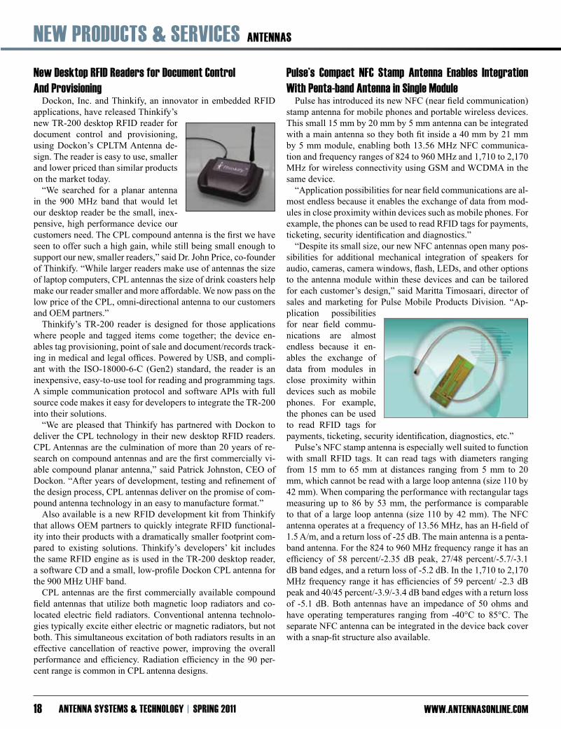
Pulse’s Compact NfC Stamp Antenna Enables integration with Penta-band Antenna in Single module Pulse has introduced its new NFC (near field communication) stamp antenna for mobile phones and portable wireless devices. This small 15 mm by 20 mm by 5 mm antenna can be integrated with a main antenna so they both fit inside a 40 mm by 21 mm by 5 mm module, enabling both 13.56 MHz NFC communica-tion and frequency ranges of 824 to 960 MHz and 1,710 to 2,170 MHz for wireless connectivity using GSM and WCDMA in the same device. “Application possibilities for near field communications are al-most endless because it enables the exchange of data from mod-ules in close proximity within devices such as mobile phones. For example, the phones can be used to read RFID tags for payments, ticketing, security identification and diagnostics.” “Despite its small size, our new NFC antennas open many pos-sibilities for additional mechanical integration of speakers for audio, cameras, camera windows, flash, LEDs, and other options to the antenna module within these devices and can be tailored for each customer’s design,” said Maritta Timosaari, director of sales and marketing for Pulse Mobile Products Division. “Ap-plication possibilities for near field commu-nications are almost endless because it en-ables the exchange of data from modules in close proximity within devices such as mobile phones. For example, the phones can be used to read RFID tags for payments, ticketing, security identification, diagnostics, etc.” Pulse’s NFC stamp antenna is especially well suited to function with small RFID tags. It can read tags with diameters ranging from 15 mm to 65 mm at distances ranging from 5 mm to 20 mm, which cannot be read with a large loop antenna (size 110 by 42 mm). When comparing the performance with rectangular tags measuring up to 86 by 53 mm, the performance is comparable to that of a large loop antenna (size 110 by 42 mm). The NFC antenna operates at a frequency of 13.56 MHz, has an H-field of 1.5 A/m, and a return loss of -25 dB. The main antenna is a penta-band antenna. For the 824 to 960 MHz frequency range it has an efficiency of 58 percent/-2.35 dB peak, 27/48 percent/-5.7/-3.1 dB band edges, and a return loss of -5.2 dB. In the 1,710 to 2,170 MHz frequency range it has efficiencies of 59 percent/ -2.3 dB peak and 40/45 percent/-3.9/-3.4 dB band edges with a return loss of -5.1 dB. Both antennas have an impedance of 50 ohms and have operating temperatures ranging from -40°C to 85°C. The separate NFC antenna can be integrated in the device back cover with a snap-fit structure also available.
ANTENNAS NEw PROduCTS & SERviCES
www.ANTENNASONliNE.COm SPRiNG 2011 ANTENNA SySTEmS & TEChNOlOGy 19
Spectrum introduces Radome-Packaged Antennas for wide Range of medium to high Gain Applications
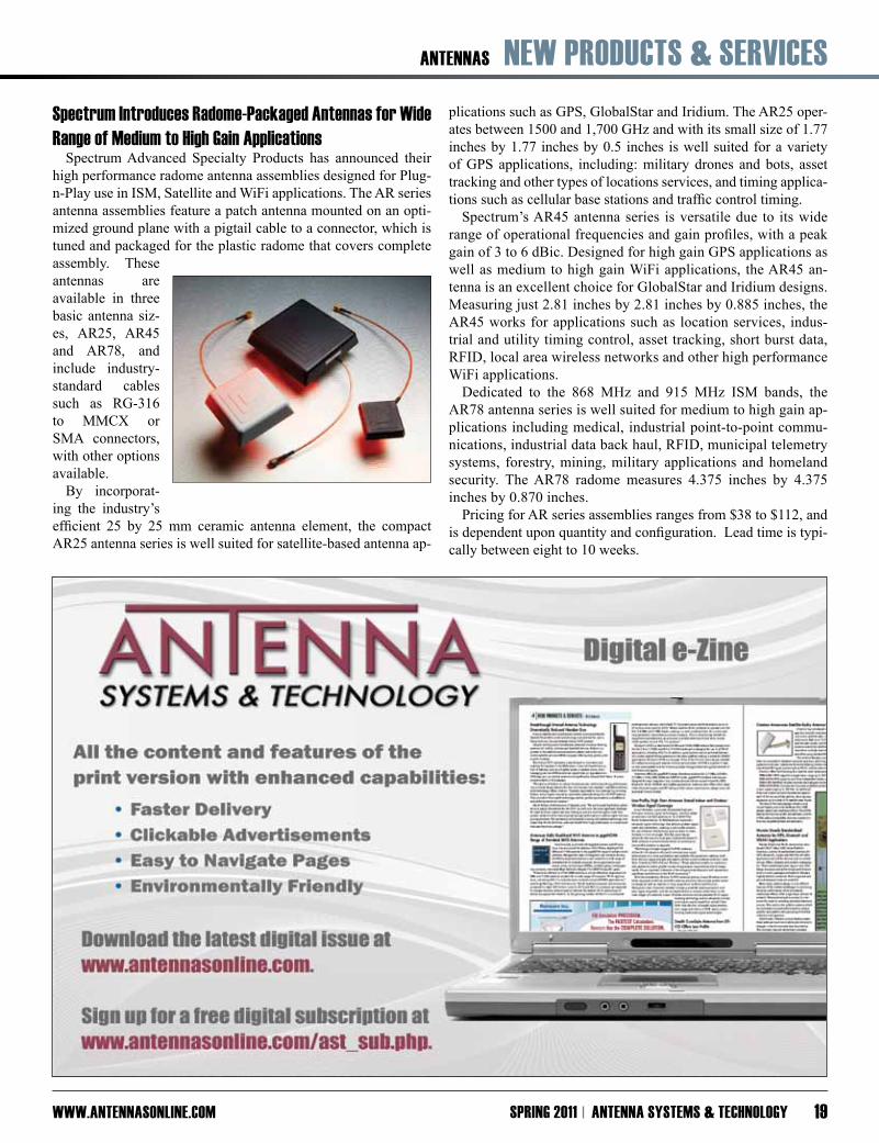
Spectrum Advanced Specialty Products has announced their high performance radome antenna assemblies designed for Plug-n-Play use in ISM, Satellite and WiFi applications. The AR series antenna assemblies feature a patch antenna mounted on an opti-mized ground plane with a pigtail cable to a connector, which is tuned and packaged for the plastic radome that covers complete assembly. These antennas are available in three basic antenna siz-es, AR25, AR45 and AR78, and include industry-standard cables such as RG-316 to MMCX or SMA connectors, with other options available.
By incorporat-ing the industry’s efficient 25 by 25 mm ceramic antenna element, the compact AR25 antenna series is well suited for satellite-based antenna ap-
plications such as GPS, GlobalStar and Iridium. The AR25 oper-ates between 1500 and 1,700 GHz and with its small size of 1.77 inches by 1.77 inches by 0.5 inches is well suited for a variety of GPS applications, including: military drones and bots, asset tracking and other types of locations services, and timing applica-tions such as cellular base stations and traffic control timing. Spectrum’s AR45 antenna series is versatile due to its wide range of operational frequencies and gain profiles, with a peak gain of 3 to 6 dBic. Designed for high gain GPS applications as well as medium to high gain WiFi applications, the AR45 an-tenna is an excellent choice for GlobalStar and Iridium designs. Measuring just 2.81 inches by 2.81 inches by 0.885 inches, the AR45 works for applications such as location services, indus-trial and utility timing control, asset tracking, short burst data, RFID, local area wireless networks and other high performance WiFi applications. Dedicated to the 868 MHz and 915 MHz ISM bands, the AR78 antenna series is well suited for medium to high gain ap-plications including medical, industrial point-to-point commu-nications, industrial data back haul, RFID, municipal telemetry systems, forestry, mining, military applications and homeland security. The AR78 radome measures 4.375 inches by 4.375 inches by 0.870 inches. Pricing for AR series assemblies ranges from $38 to $112, and is dependent upon quantity and configuration. Lead time is typi-cally between eight to 10 weeks.

NEw PROduCTS & SERviCES ANTENNAS
www.ANTENNASONliNE.COmANTENNA SySTEmS & TEChNOlOGy SPRiNG 201120
Panel Antenna improves directional Communication Antenna Factor has released the PN Series of panel mount an-
tennas. PN Series antennas are designed for long-distance direc-tional communication among wireless links. The 16 dBi gain and 23º horizontal, 23º vertical directivity are improved from typical Yagi antennas, increasing the range and reliability of the wire-less link. The antenna package is rugged and fully weatherized, making the anten-na well suited for indoor or outdoor applications. Each antenna includes complete mount-ing hardware for standard masts. Priced at less than $50.00 each in volume quantities, PN Series panel antennas deliver both value and outstanding performance.
dual-band, Ceiling mount mimO Omnidirectional Antennas PCTEL’s PCTCMI2458-6 and PCTCMI2458-3 dual-band MIMO antennas provide coverage of 2.4 to 2.5 GHz Wi-Fi and 4.9 to 5.9 GHz Public Safety, Wi-Fi and WiMAX broadband wireless frequencies in an at-tractive, low profile housing. These an-tennas are designed for in-building ceil-ing mount instal-lations utilizing 802.11n MIMO radios. Two models are available for use with six-port or three-port MIMO devices.
Send your industry news and new product releases to Heather Krier at [email protected]
COmPONENTS NEw PROduCTS & SERviCES
www.ANTENNASONliNE.COm SPRiNG 2011 ANTENNA SySTEmS & TEChNOlOGy 21
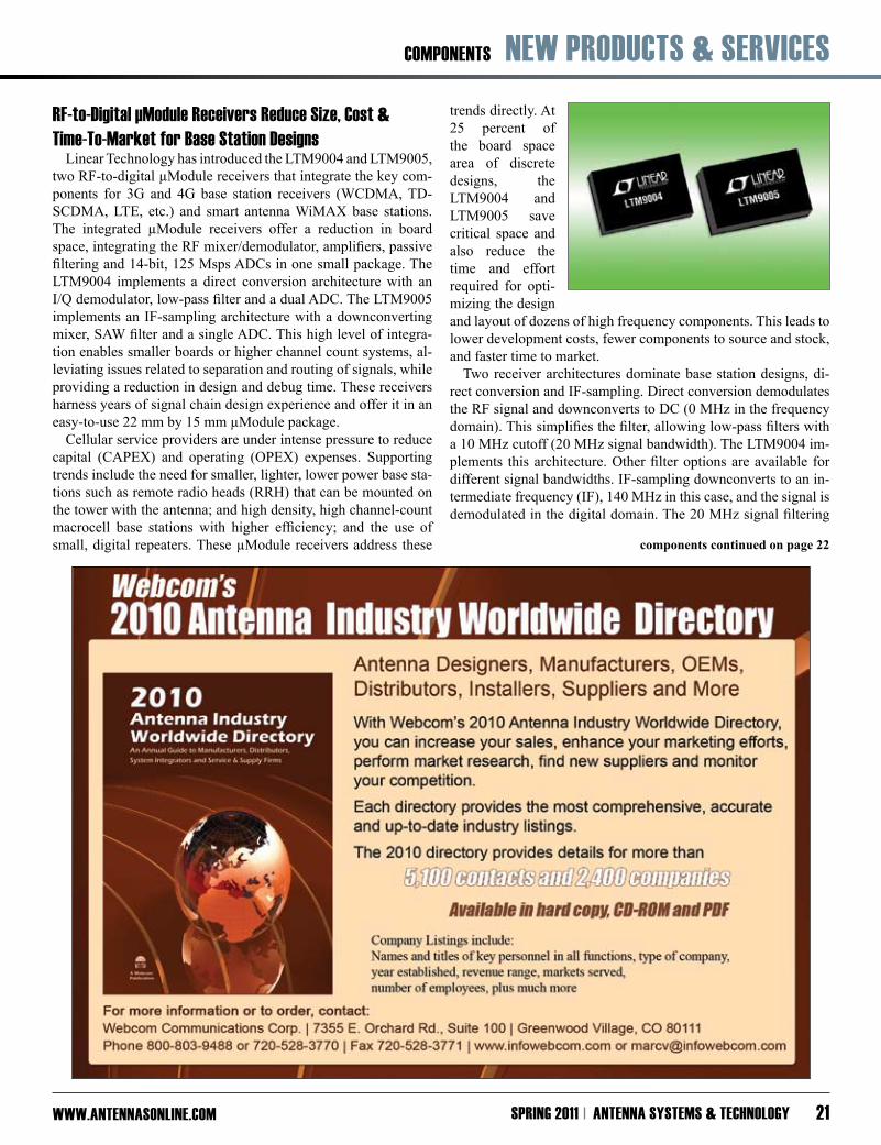
Rf-to-digital µmodule Receivers Reduce Size, Cost & Time-To-market for Base Station designs Linear Technology has introduced the LTM9004 and LTM9005, two RF-to-digital µModule receivers that integrate the key com-ponents for 3G and 4G base station receivers (WCDMA, TD-SCDMA, LTE, etc.) and smart antenna WiMAX base stations. The integrated µModule receivers offer a reduction in board space, integrating the RF mixer/demodulator, amplifiers, passive filtering and 14-bit, 125 Msps ADCs in one small package. The LTM9004 implements a direct conversion architecture with an I/Q demodulator, low-pass filter and a dual ADC. The LTM9005 implements an IF-sampling architecture with a downconverting mixer, SAW filter and a single ADC. This high level of integra-tion enables smaller boards or higher channel count systems, al-leviating issues related to separation and routing of signals, while providing a reduction in design and debug time. These receivers harness years of signal chain design experience and offer it in an easy-to-use 22 mm by 15 mm µModule package. Cellular service providers are under intense pressure to reduce capital (CAPEX) and operating (OPEX) expenses. Supporting trends include the need for smaller, lighter, lower power base sta-tions such as remote radio heads (RRH) that can be mounted on the tower with the antenna; and high density, high channel-count macrocell base stations with higher efficiency; and the use of small, digital repeaters. These µModule receivers address these
trends directly. At 25 percent of the board space area of discrete designs, the LTM9004 and LTM9005 save critical space and also reduce the time and effort required for opti-mizing the design and layout of dozens of high frequency components. This leads to lower development costs, fewer components to source and stock, and faster time to market. Two receiver architectures dominate base station designs, di-rect conversion and IF-sampling. Direct conversion demodulates the RF signal and downconverts to DC (0 MHz in the frequency domain). This simplifies the filter, allowing low-pass filters with a 10 MHz cutoff (20 MHz signal bandwidth). The LTM9004 im-plements this architecture. Other filter options are available for different signal bandwidths. IF-sampling downconverts to an in-termediate frequency (IF), 140 MHz in this case, and the signal is demodulated in the digital domain. The 20 MHz signal filtering
components continued on page 22
NEw PROduCTS & SERviCES COmPONENTS
www.ANTENNASONliNE.COmANTENNA SySTEmS & TEChNOlOGy SPRiNG 2011 22
is done with a surface acoustical wave (SAW) filter integrated in the LTM9005. Other filter bandwidths are available.
The LTM9004 and LTM9005 are packaged in a 22 mm by 15 mm LGA package, utilizing a multilayer substrate that shields sen-sitive analog lines from the digital traces to minimize digital feed-back. Supply and reference bypass capacitance is placed inside the µModule package, tightly coupled to the die, providing a space, cost and performance advantage over traditional packaging. The LTM9004 and LTM9005 are sampling today with pro-duction volumes next quarter, priced at $75.00 each in 1,000 piece quantities.
Antenova launches m10372 GPS RAdiONOvA with CSR’s SiRfstariv Architecture
Antenova Ltd., the integrated antenna and RF solutions compa-ny, has released the M10372 GPS RADIONOVA, a planar mount GPS Radio Antenna Module incorporating CSR’s SiRFstarIV GPS chipset with Antenova’s antenna technology in a compact low profile package. Antenova further announced the M10372 is well suited for a multitude of embedded GPS, machine-to-machine (M2M) and mobile device applications such as personal navigation devices (PNDs), automatic vehicle locators (AVLs), trackers and por-table media play-ers (PMPs). Greg McCray, CEO of Anteno-va said, “CSR is a recognized leader in the GPS semiconductor market and the new SiRFstarIV archi-tecture provides many new features and benefits for Antenova’s GPS RADIONOVA customers. Some of the new features include adaptive micro-power controller to maintain hot-start conditions with minimal power consumption and active jammer remover, which helps maximize performance in potentially noisy environ-ments. The improved tracking, navigation and acquisition sensi-tivity of the new SiRFstarIV chip combined with Antenova’s high performing omni-directional antenna makes the M10372 a well suited GPS system solution for next generation embedded device and M2M applications. And the M10372 has been designed to provide existing GPS RADIONOVA customers an easy migra-tion path for their next generation products.” The M10372 is an integrated GPS RF antenna module suit-able for L1-band GPS and A-GPS systems. The device combines CSR’s SiRFstarIV GSD4e GPS receiver IC with Antenova’s an-tenna technology. All front-end components are contained in a 29 by 13 by 4.7 mm single package laminate base module providing a complete GPS receiver for optimum performance. M10372 op-erates on a single 1.8 V positive bias supply with ultra low power consumption and available low power modes for further power savings. M10372 is supported by SiRF stand alone software and
is compatible with UART, SPI and I2C host processor interfaces. Custom versions of the module can also incorporate an antenna switch for optional active antenna connection.
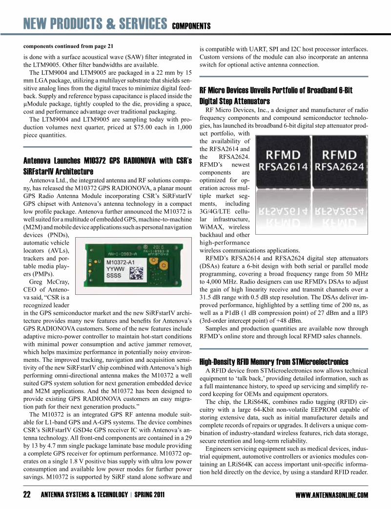
Rf micro devices unveils Portfolio of Broadband 6-Bit digital Step Attenuators RF Micro Devices, Inc., a designer and manufacturer of radio frequency components and compound semiconductor technolo-gies, has launched its broadband 6-bit digital step attenuator prod-uct portfolio, with the availability of the RFSA2614 and the RFSA2624. RFMD’s newest components are optimized for op-eration across mul-tiple market seg-ments, including 3G/4G/LTE cellu-lar infrastructure, WiMAX, wireless backhaul and other high-performance wireless communications applications. RFMD’s RFSA2614 and RFSA2624 digital step attenuators (DSAs) feature a 6-bit design with both serial or parallel mode programming, covering a broad frequency range from 50 MHz to 4,000 MHz. Radio designers can use RFMD's DSAs to adjust the gain of high linearity receive and transmit channels over a 31.5 dB range with 0.5 dB step resolution. The DSAs deliver im-proved performance, highlighted by a settling time of 200 ns, as well as a P1dB (1 dB compression point) of 27 dBm and a IIP3 (3rd-order intercept point) of +48 dBm. Samples and production quantities are available now through RFMD’s online store and through local RFMD sales channels.
high-density Rfid memory from STmicroelectronics A RFID device from STMicroelectronics now allows technical equipment to ‘talk back,’ providing detailed information, such as a full maintenance history, to speed up servicing and simplify re-cord keeping for OEMs and equipment operators. The chip, the LRiS64K, combines radio tagging (RFID) cir-cuitry with a large 64-Kbit non-volatile EEPROM capable of storing extensive data, such as initial manufacturer details and complete records of repairs or upgrades. It delivers a unique com-bination of industry-standard wireless features, rich data storage, secure retention and long-term reliability. Engineers servicing equipment such as medical devices, indus-trial equipment, automotive controllers or avionics modules con-taining an LRiS64K can access important unit-specific informa-tion held directly on the device, by using a standard RFID reader.
components continued from page 21
COmPONENTS / mATERiAlS NEw PROduCTS & SERviCES
www.ANTENNASONliNE.COm SPRiNG 2011 ANTENNA SySTEmS & TEChNOlOGy 23
This on-board stor-age can eliminate any need to retrieve paper records or ac-cess an online da-tabase. The unit’s service history can be updated in the LRiS64K memory for access during subsequent inspec-tion or servicing. This feature can save downtime and help reduce MRO (Maintenance, Repair & Operations) costs in sectors such as healthcare, aviation, logistics, oil and chemicals, construction and manufacturing.
The LRiS64K is a long-range 13.56 MHz device, based on the international ISO 15693 and ISO 18000-3 mode 1 standards for RFID devices and capable of co-existing with other devices with-in range. Its integrated tuning capacitor simplifies connection to an external antenna. The memory can retain data for more than 40 years and withstand more than one million write/erase cycles.
The LRiS64K is starting in mass production now. It is available in bumped and sawn wafer suitable for Direct Chip Attachment (DCA).
high Performance halogen-free laminates for high Temperature, multilayer Circuit Applications
Rogers Corp. has introduced the XT/duroid thermoplastic lam-inate materials, well suited for high frequency multilayer circuits in demanding operating environments. The XT/duroid product line includes XT/duroid 8000 laminates for multilayer designs with as many as five layers and XT/duroid 8100 laminates for constructions with six or more circuit layers. Both laminates feature thin halogen-free dielectrics and are available with low-profile copper foil cladding for use in double-sided and multi-layer printed circuit boards (PCBs). Low profile copper bonded directly to the dielectric without the use of adhesives results in low insertion loss for these thin materials. The flame-retardant laminates are thermally and chemically robust with high melting points, making them well suited for rugged military and aerospace applications, including airborne lightning strike protection circuits, phased-array antennas and unmanned aerial vehicles (UAVs). These materials exhibit low outgassing characteristics, required for use in high-vacuum, deep-space applications. Rogers’ XT/duroid 8000 laminates feature a z-axis dielectric constant of 3.23 ±0.05 at 10 GHz and a dissipation factor of 0.0035 or less at 10 GHz. They deliver stable electrical perfor-mance over wide frequency ranges, with a low thermal coefficient of dielectric constant of +7 ppm/°C from -50°C to 150°C. They also exhibit improved thermal conductivity of 0.35 W/m/°K. XT/duroid 8000 laminates can withstand extreme thermal conditions, with an estimated maximum operating temperature of greater than 210°C and melt temperature well beyond that of PTFE-based circuit materials. XT/duroid 8000 circuit materials
are designed for ease of processing, and are compatible with lead-free-solder assembly methods. For more complex multilayer circuit constructions requiring improved stability, XT/duroid 8100 laminates benefit from the additional dimensional stability of a reinforced woven-glass resin sys-tem. As a result, they can support multilayer circuits of six and more layers while providing the thermal and chemi-cal ruggedness, and outstanding electrical performance, of XT/duroid 8000 laminates. Both laminate materials are available with dielectric thickness of 0.002 inches (0.0508 mm) with 0.5-oz. low-profile electrodeposited copper foil clad-ding. XT/duroid 8100 is also available with dielectric thickness of 0.004 inches (0.1016 mm).
Are you an A, B or C? Your subscription to AS&T might be about to expire. Check your status in the colored box located in the mailing label on the front cover. Subscribe at www.AntennasOnline.com
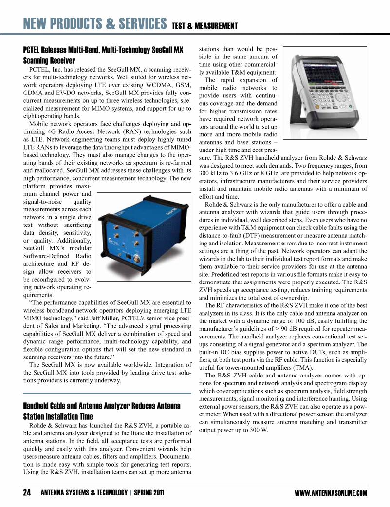
NEw PROduCTS & SERviCES TEST & mEASuREmENT
www.ANTENNASONliNE.COmANTENNA SySTEmS & TEChNOlOGy SPRiNG 201124
PCTEl Releases multi-Band, multi-Technology SeeGull mX Scanning Receiver
PCTEL, Inc. has released the SeeGull MX, a scanning receiv-ers for multi-technology networks. Well suited for wireless net-work operators deploying LTE over existing WCDMA, GSM, CDMA and EV-DO networks, SeeGull MX provides fully con-current measurements on up to three wireless technologies, spe-cialized measurement for MIMO systems, and support for up to eight operating bands. Mobile network operators face challenges deploying and op-timizing 4G Radio Access Network (RAN) technologies such as LTE. Network engineering teams must deploy highly tuned LTE RANs to leverage the data throughput advantages of MIMO-based technology. They must also manage changes to the oper-ating bands of their existing networks as spectrum is re-farmed and reallocated. SeeGull MX addresses these challenges with its high performance, concurrent measurement technology. The new platform provides maxi-mum channel power and signal-to-noise quality measurements across each network in a single drive test without sacrificing data density, sensitivity, or quality. Additionally, SeeGull MX’s modular Software-Defined Radio architecture and RF de-sign allow receivers to be reconfigured to evolv-ing network operating re-quirements. “The performance capabilities of SeeGull MX are essential to wireless broadband network operators deploying emerging LTE MIMO technology,” said Jeff Miller, PCTEL’s senior vice presi-dent of Sales and Marketing. “The advanced signal processing capabilities of SeeGull MX deliver a combination of speed and dynamic range performance, multi-technology capability, and flexible configuration options that will set the new standard in scanning receivers into the future.” The SeeGull MX is now available worldwide. Integration of the SeeGull MX into tools provided by leading drive test solu-tions providers is currently underway.
handheld Cable and Antenna Analyzer Reduces Antenna Station installation Time
Rohde & Schwarz has launched the R&S ZVH, a portable ca-ble and antenna analyzer designed to facilitate the installation of antenna stations. In the field, all acceptance tests are performed quickly and easily with this analyzer. Convenient wizards help users measure antenna cables, filters and amplifiers. Documenta-tion is made easy with simple tools for generating test reports. Using the R&S ZVH, installation teams can set up more antenna
stations than would be pos-sible in the same amount of time using other commercial-ly available T&M equipment. The rapid expansion of mobile radio networks to provide users with continu-ous coverage and the demand for higher transmission rates have required network opera-tors around the world to set up more and more mobile radio antennas and base stations – under high time and cost pres-sure. The R&S ZVH handheld analyzer from Rohde & Schwarz was designed to meet such demands. Two frequency ranges, from 300 kHz to 3.6 GHz or 8 GHz, are provided to help network op-erators, infrastructure manufacturers and their service providers install and maintain mobile radio antennas with a minimum of effort and time. Rohde & Schwarz is the only manufacturer to offer a cable and antenna analyzer with wizards that guide users through proce-dures in individual, well described steps. Even users who have no experience with T&M equipment can check cable faults using the distance-to-fault (DTF) measurement or measure antenna match-ing and isolation. Measurement errors due to incorrect instrument settings are a thing of the past. Network operators can adapt the wizards in the lab to their individual test report formats and make them available to their service providers for use at the antenna site. Predefined test reports in various file formats make it easy to demonstrate that assignments were properly executed. The R&S ZVH speeds up acceptance testing, reduces training requirements and minimizes the total cost of ownership. The RF characteristics of the R&S ZVH make it one of the best analyzers in its class. It is the only cable and antenna analyzer on the market with a dynamic range of 100 dB, easily fulfilling the manufacturer’s guidelines of > 90 dB required for repeater mea-surements. The handheld analyzer replaces conventional test set-ups consisting of a signal generator and a spectrum analyzer. The built-in DC bias supplies power to active DUTs, such as ampli-fiers, at both test ports via the RF cable. This function is especially useful for tower-mounted amplifiers (TMA). The R&S ZVH cable and antenna analyzer comes with op-tions for spectrum and network analysis and spectrogram display which cover applications such as spectrum analysis, field strength measurements, signal monitoring and interference hunting. Using external power sensors, the R&S ZVH can also operate as a pow-er meter. When used with a directional power sensor, the analyzer can simultaneously measure antenna matching and transmitter output power up to 300 W.

wimAX / wi-fi / lTE NEw PROduCTS & SERviCES
www.ANTENNASONliNE.COm SPRiNG 2011 ANTENNA SySTEmS & TEChNOlOGy 25
Rfmd unveils high-Performance Power Amplifier iC RF Micro Devices, Inc., a designer and manufacturer of high-
performance radio frequency components and compound semi-conductor technologies, has unveiled the RF5632, a 2.3 to 2.7 GHz power amplifier IC. The RF5632 is optimized specifically for WiMAX systems and can be designed into multiple applica-tions, including customer prem-ises equipment (CPE), gateways, access points, LTE wireless infrastructure and WiFi-based wireless high definition interface (WHDI) for wireless video dis-tribution networks. The RF5632 integrates a 3-stage PA and power detec-tor into a 4 mm by 4 mm QFN package, minimizing customer design footprint requirements. Additionally, the RF5632 oper-ates from a standard 5 V supply, eliminating additional power supply requirements, enhancing design flexibility and lowering bill-of-material costs (BOM). The RF5632 is also fully DC and RF tested including EVM at the rated output power, maximizing application yields and accelerating time-to-market. The RF5632 deliversan EVM of 2.5 percent and meets or exceeds WiMAX and LTE spectral mask requirements with an output power of 28 dBm in the 2.3 to 2.4 GHz, 2.4 to 2.5 GHz and 2.5 to 2.7 GHz frequency ranges. The bias of the PA may be controlled to accommodate a 22 dB gain step to increase the dynamic range of the system. The RF5632 offers high gain of 34 dB and high linear output power, with best-in-class efficiency. The RF5632 maintains linearity over a wide range of tempera-tures and power outputs while the external match enables tuning for output power over multiple bands. The RF5632 also features internal input and inter-stage matching, a power-down mode and power detection. The RF5632 features InGaP HBT semiconduc-tor technology and is packaged in a leadless chip carrier with a backside ground. The RF5632 starts at $3.10 per 10,000 units.
Roving Networks Releases low Power Complete wi-fi module
Roving Networks, a provider of wireless solutions, has re-leased the RN-171, its latest ultra-low power Wi-Fi module. The module complements Roving Networks’ line of full-featured Wi-Fi modules that are small scale, completely configurable with on-board TCP/IP stack and networking functions. With a list price of $29.00 and a volume price of $19.95 at 1,000 pieces, the RN-171 opens new markets for embedded Wi-Fi devices.
Measuring 26 mm by 18 by 3.1 mm the RN-171 is 34 percent smaller than its predecessor, the RN-131. The RN-171 is a com-prehensive networking solution that includes a 2.4 GHz radio, baseband processor and a host of networking application fea-tures. No external processor or driver is required, reducing cus-tomers’ integration and development effort. The output power is configurable from 10 dBm to 0 dBm. Multiple antenna options provide the flexibility for on-board PCB trace, chip, wire, or external U.FL connector. “The RN-171, the latest module in our WiFly product family, is built upon our proven 802.11 b/g silicon,” said Mike Conrad, founder and CEO of Roving Networks. “Its small size and low power is perfect for battery-powered applications such as remote sensors and asset tracking devices.” The RN-171 is a standalone, wireless networking device that supports UDP, TCP, DNS, DHCP, ARP, ICMP and HTML client. The module is an industrial (-45°C to 85°C) grade temperature range part. The RN-171 hardware interfaces include 10 bidirec-tional IO and 8 analog inputs, UART with data rates up to 921 Kbps TX, 500 Kbps RX, and SPI slave with up to 2.5 Mbps data rate. The on-board hardware crypto engine supports Wi-Fi authen-tication for WEP-128, WPA-PSK (TKIP) and WPA2-PSK (AES). The RN-171 module is FCC, IC, EN and Wi-Fi alliance certified.
iNduSTRy NEwS
www.ANTENNASONliNE.COmANTENNA SySTEmS & TEChNOlOGy SPRiNG 201126
Syntonics’ fORAX Rf-Over-fiber Antenna Extension System Joins the war
Syntonics LLC, based in Columbia, Md., revealed that its FORAX RF-over-fiber product is now operating as the High Antennas for Radio Communications (HARC) component of an US Army Persistent Threat Detection System (PTDS) aero-stat in a forward-located theater of war. Reports indicate that all SINCGARS and EPLRS radio links have been operational for several months, enabling communications at long ranges not before achievable. Under a contract with Lockheed Martin, Syntonics delivered two six-radio aerostat-mounted HARC systems and two ship-sets of spare modules. Syntonics delivered a third HARC sys-tem under a separate Army purchase order. The HARC system places a lightweight communications payload with SINCGARS and EPLRS antennas high aloft on a tethered aerostat, while the six radios remain on the ground in the command post (CP). The airborne antenna allows communications over obstacles in moun-tainous terrain and over tall buildings in urban settings while keeping the radios in the CP, thereby eliminating operational dif-ficulties in controlling the radios and potential for loss of com-munications. The radios’ RF signals are transmitted and received over a single optical fiber in the aerostat’s tether. This contract from Lockheed Martin fulfills a US Army re-quirement for a deployable communications capability to extend the range of SINCGARS and EPLRS radios and overcome line-of-sight (LOS) obstructions in the mountains of Afghanistan and the urban environment of Iraq. The FORAX product line, deployed since 2004 by US and foreign militaries, moves antennas away from command posts; eliminates the electronic and visual signature of nearby antennas; increases the security of people and equipment in the CP and enables radios and crypto equipment to be operated from inside secure facilities. This new application for airborne antennas adds another valuable communications tool for the warfighter. Syntonics recently added HF and GPS capability to its already-fielded SINCGARS, VHF/UHF, UHF TACSAT and EPLRS modules. To date, Syntonics has fielded over 200 FORAX links around the world.
harris Corp. Awarded Contract to Provide All-weatherimaging Payload Onboard New military Spacecraft
Harris Corp., a communications and information technology company, has been awarded a 30-month, $42 million contract by Sierra Nevada Corp. to supply antenna and radar electronics for a satellite that will provide military commanders in the field with timely, high-resolution radar imagery of the earth's surface – re-gardless of weather conditions or time of day.
Harris will design, build and integrate the synthetic aperture radar (SAR) satellite payload for Sierra Nevada as part of NASA's Rapid Response Space Works and Modular Space Vehicles program for the US Department of Defense's Operationally Responsive Space (ORS) Office. ORS is a joint NASA/DoD initiative with the char-ter to field modular payloads rapidly and inexpensively.
The payload architecture, designed to support a new family of modular military satellites, offers flexibility to support multiple missions with minimal changes in the basic design. SAR is the second payload to be developed by the ORS Office and will pro-duce high-resolution radar imagery of the earth’s surface, even during darkness or inclement weather. “Harris has decades of experience producing trusted solutions for satellite antennas and electronics, and we are applying this ca-pability to small yet highly advanced payloads,” said Bill Gattle, vice president, Space Communications Programs. “This contract brings the benefits of our proven imaging technology to warfight-ers while also furthering our goal to become a major presence in the small-payload community.”
Taoglas Enters into a wireless design Partnership Agreement with microchip Technology Taoglas Limited, a provider of antenna solutions to the M2M mar-ket, has entered a Wireless Design Partnership agreement with Mi-crochip Technology, Inc. Surface-mount technology antennas such as Taoglas’ PA.25 Cellular (2G/3G/3.5G) and SGP.25D GPS patch are just two of the antennas chosen. Microchip also selected Taoglas’ automotive-approved “Titan” AA.105 Active External GPS IP67 an-tenna, for customers looking for an external antenna solution. “After speaking with wireless-module partners and testing the antenna technology ourselves, we are pleased to select Taoglas as an Antenna Design partner,” said Cheri Keller, Microchip’s senior manager, Worldwide Design Partner Program. “We are excited to partner with a quality organization like Mi-crochip,” said Tim Dolan, North American Sales manager with Taoglas. “We are the market leader in antennas for wireless M2M applications. With the investments both companies are making in next-generation wireless solutions, and the synergies between the two organizations, together we make a powerful solutions choice for wireless M2M.” Taoglas’ ceramic SMT antennas deliver high efficiency for a giv-en ground-plane area, without the loss associated with traditional cabled solutions. They eliminate the need for tooling and NRE fees. This means the range is available “off the shelf” at any quantity, delivered on tape and reel. All that is needed is for the customer to place the antenna on one of the short ends of their main device board and design a straight 50 Ohm CPW transmission line direct to the module. Tuning of the matching circuit by way of changing simple component values may be necessary. These features allow the antennas to be tuned on the customer side, during integration, and speed up the design cycle dramatically.
SAiC wins $45 million Task Order Science Applications International Corp. has been awarded a task order by the US Department of Homeland Security (DHS), Customs and Border Protection (CBP), to modernize existing tacti-cal communications systems used by law enforcement agents and officers protecting the Nation's borders. The task order has a 24

iNduSTRy NEwS
www.ANTENNASONliNE.COm SPRiNG 2011 ANTENNA SySTEmS & TEChNOlOGy 27
month base period of performance and a total value of $45 million. Work will be performed in Washington, DC, New Mexico and Tex-as. The task order was awarded under the DHS EAGLE contract. The goal of CBP’s Tactical Communications Modernization Program is to upgrade Land Mobile Radio (LMR) communica-tions capabilities for field personnel in 20 geographic focus areas across the US. Effective LMR communications are vital to of-ficer safety in the field when conducting border patrol, customs inspection and air/marine operations. Under this task order, SAIC will provide services and equipment to CBP in support of the modernization project within the El Paso, Texas, focus area. The modernization work will include encryption technology to help ensure secure communications, Global Positioning System technology to track agent and officer location and interoperable digital technology that will allow for greater coverage and user capacity. SAIC will also provide support in areas including en-gineering design and analysis; equipment configuration; systems installation, testing and evaluation; training and field operations support services. “We are honored to support the CBP mission by providing a fully integrated LMR communications system that will serve as a critical lifeline for the agents and officers protecting the US bor-der,” said Doug Wagoner, SAIC senior vice president and busi-ness unit general manager.
Boeing SkyTerra 1 Satellite Sends first Signals from Space Boeing has received the first on-orbit signals from Light-Squared’s SkyTerra 1 following the satellite's launch on Nov. 14 on an International Launch Services Proton vehicle from the Bai-konur Cosmodrome in Kazakhstan. Signal acquisition indicates that the satellite is healthy and ready to begin operational testing and on-orbit maneuvers. SkyTerra 1 is a Boeing 702HP satellite designed for geomo-bile services that will provide satellite coverage as part of Light-Squared’s new broadband mobile wireless network in the US. “There is a large and rapidly growing demand for data services to US businesses, individuals and other end users, and Boeing has accomplished the first step in delivering this capability to Light-Squared with the successful launch of SkyTerra 1,” said Craig Cooning, vice president and general manager, Boeing Space & Intelligence Systems. “Boeing has been designing advanced geo-mobile satellite systems for the past 13 years, and our experience enables us to provide LightSquared with a high-value solution.” When operational, SkyTerra 1 will combine with ground-based beam-forming (GBBF) equipment and ground stations to form LightSquared’s first Space-Based Network (SBN), which will en-able faster service and broader access to smaller mobile devices for millions of users in the US. The Boeing-built SBN will ben-efit from the satellite’s 22-meter L-band reflector, which reduces the need for larger antennas and battery-draining receivers inside mobile handsets.
Complete form and fax to 720-528-3771 or submit online at www.AntennasOnline.com
Free Subscription ApplicationDo you wish to receive Antenna Systems & Technology Free of Charge? (Outside US $60) � Yes � NoPlease select your desired format (check only one): � Electronic Copy � Hard Copy
X Signature (required) __________________________________ Date ________________________________________________
Print Name ________________________________________________________________________________________________
Title ______________________________________________________________________________________________________
Company__________________________________________________________________________________________________
Address __________________________________________________________________________________________________
City __________________________________ State ____________________________ ZIP ____________________________
Business Phone ______________________________ Business Fax__________________________________________________
E-mail (required for electronic format) __________________________________________________________________________
You may receive renewal reminders via email. If you do not want to receive other business related, third party email offers, please check here. �
� 1 System OperatorA. � Cellular/Wireless CarrierB. � BroadcastC. � Public Safety
� 3 Engineering/Consulting Firm� 4 OEM of Wireless/RF Products � 5 Integrator/Value-Added Distributor of
Antennas/Antenna Systems � 6 Wholesale/Retail Dealer of Antennas
� 7 Provider of Towers & Related Equipment,Site Services
� 9 Manufacturer of Antennas/Antenna Systems� 10 Vendor/Supplier of Components, Supplies
and Equipment � 11 Assn./Publication/Regulatory
Agency/Education
� 20 General/Corporate Management� 21 Engineer/Technical Management� 22 Operations Management� 23 Finance/Purchasing
� 24 Systems Integration� 25 Engineering Consulting� 26 Legal and Professional Services
A. Company’sprimary productor service
(Check one)
B. What is your principal job function?(Check one)
--------------------------------------------------------------------------------------------------------------------------------------------------------------------------------------------------------------------------------------------------------------
--------------------------------------------------------------------------------------------------------------------------------------------------------------------------------------------------------------------------------------------------------------

iNduSTRy NEwS
www.ANTENNASONliNE.COmANTENNA SySTEmS & TEChNOlOGy SPRiNG 201128
LightSquared’s SBN will combine with a ground network of more than 40,000 base stations built to offer ground coverage, satellite coverage or a combination of the two. LightSquared plans to be-gin rolling out its nationwide wholesale 4G LTE wireless network in the first four markets in the second half of 2011.
Boeing and LightSquared will soon begin on-orbit maneuvers to move SkyTerra 1 into its test orbit location, where the space-craft will begin deployments and signal testing. After validat-ing the satellite’s subsystems and the SBN with ground stations, LightSquared will accept the SBN from Boeing in early 2011. Boeing, the prime contractor for LightSquared’s satellites, built SkyTerra 1 at its integration and test complex in El Segundo. Harris Corp. of Melbourne, Fla., developed the satellite’s L-band reflector. ViaSat’s Comsat Laboratories in Germantown, Md., is providing the GBBF equipment, the uplink beacon stations and the ground stations’ control and monitoring system. SED Systems of Saskatoon, Canada, is providing the antennas, RF elements and integration services at the gateway stations.
New NiST Publication Provides Security Guidance for wimAX Technologies
A new publication from the National Institute of Standards and Technology (NIST) provides technical guidance to government agencies and other organizations interested in mitigating risks with WiMAX (Worldwide Interoperability for Microwave Ac-cess) networks.
Emergency WiMAX nets have been used in disaster zones where the communication infrastructure was destroyed, such as along the coast of the Gulf of Mexico after Hurricane Katrina.
Special Publication 800-127 “Guide to Security for WiMAX Technologies” discusses WiMAX technology’s topologies, com-ponents, certifications, security features and related security con-cerns. It covers the IEEE 802.16 standard for WiMAX and its evolution up to the 2009 version.
The main threats to all wireless networks are denial of ser-vice attacks, eavesdropping, message modification and re-source misappropriation.
New Spirent mimO Test Solution Configuration helps the industry deliver on the Promise of Td-lTE
Spirent Communications, a provider of testing solutions for wireless networks, devices and services, has announced that a major network equipment manufacturer has installed the Spirent SR5500 Wireless Channel Emulator for testing beamforming ca-pabilities of Time Domain-Long Term Evolution (TD-LTE) base stations at its laboratories in Shanghai, China. Performance testing of network equipment is critical for the successful deployment of TD-LTE, a technology that is expected to find widespread adop-tion in China, India and several other countries in Asia. “Between ongoing work in China and probable deployment in India’s Broadband Wireless Access bands, TD-LTE may well
be the wireless technology of choice for hundreds of millions of subscribers,” said Rob VanBrunt, vice president of Spirent’s Wireless business. “While the complexities of advanced antenna techniques require careful design and testing, the reward is very high data throughput capability. We look forward to seeing the results of the industry’s hard work, and are delighted to be a part of enabling it.” Unlike the Frequency-Domain implementation of LTE current-ly being deployed in North America and Europe, TD-LTE uses a single shared frequency band for both uplink and downlink. Beam-forming is an adaptive antenna technique used to maximize the performance of wireless systems. It typically makes use of eight antennas on the base station and two on the mobile device (8x2). Spirent’s SR5500 is used to simplify and accelerate the test-ing associated with complex beamforming implementations. The SR5500 is a modular system, which creates realistic synchronized radio paths by affecting a transmitted radio signal in the same way as a live environment (i.e. noise, radio-wave reflections). For this application, Spirent has developed a fully-integrated 8x2 bi-directional (downlink and uplink) SR5500 configuration con-trolled by a single software user interface.
mediaG3 Contracts with Aerius international to Sell Aerius Equipped mobile Phones worldwide MediaG3, Inc. has contracted with Aerius International, Inc. to sell smart and mobile phones equipped with Aerius patented antennas in the US and worldwide. “MediaG3 is very excited to offer Aerius equipped products that show increased battery life and range in smart phones and mobile devices,” said Val Westergard, MediaG3’s chairman and CEO. “Aerius products clearly demonstrate greatly improved performance that will give us a very clear advantage to offer the world’s mobile device market.” “Aerius won the Frost & Sullivan 2009 Green Technology Award in Wireless Technologies based on the benefits Aerius equipped phones deliver including two to four more hours of bat-tery life, increased handset range, while reducing the frequency of dropped calls over 60 percent,” said Bill Luxon, Aerius CEO. Frost & Sullivan also reported widespread deployment of Aeri-us equipped phones, “By allowing cellsites to work efficiently by using up to 50 percent less power, this (Aerius International) technology, when widely deployed, has the potential to reduce cell site CO2 emissions by up to 1.2 million tons per year just in the US.”
Send industry news to Heather Krier at [email protected]

mARkETPlACE
www.ANTENNASONliNE.COm SPRiNG 2011 ANTENNA SySTEmS & TEChNOlOGy 29
AH Systems. . . . . . . . . . . . . . . . . . . . . . . . . . . . . . . . . . . . . . . . . . 32www.ahsystems.com
Antenna Factor / Linx Technologies . . . . . . . . . . . . . . . . . . . . .9www.linxtechnologies.com
Antenna Research Associates. . . . . . . . . . . . . . . . . . . . . . . . . . . 5www.ara-inc.com
Applied Radar, Inc . . . . . . . . . . . . . . . . . . . . . . . . . . . . . . . . . . . . 29www.appliedradar.com
Composites Manufacturing 2011 . . . . . . . . . . . . . . . . . . . . . . . 13www.sme.org
ETS Lindgren.. . . . . . . . . . . . . . . . . . . . . . . . . . . . . . . . . . . . . . . . 7www.ets-lindgren.com
IWCE 2011. . . . . . . . . . . . . . . . . . . . . . . . . . . . . . . . . . . . . . . . . 15 www.iwceexpo.com
RF Industries . . . . . . . . . . . . . . . . . . . . . . . . . . . . . . . . . . . . . . . . .9www.rfindustries.com
Rotating Precision Mechanisms, Inc. . . . . . . . . . . . . . . . . . . . . 11www.rpm-psi.com
Spectrum Control. . . . . . . . . . . . . . . . . . . . . . . . . . . . . . . . . . . . . .7www.spectrumcontrol.com
iNdEX Of AdvERTiSERS
Interested in Advertising in AS&T?Contact Laura Mayo at [email protected] or call
800-803-9488 x130 for more information.
February 2011
2/2 - 2/3, Smart Grid Summit, Miami, FL
2/7 - 2/9, IDGA Software Radio Communica-
tions Summit, Vienna, VA
2/7 - 2/9, 4th Annual Military Radar Summit,
Washington, DC
2/21 - 2/24, NATE 2011, Oklahoma City, OK
March 2011 3/7 - 3/11, IWCE 2011, Las Vegas, NV
3/14 - 3/17, Satellite 2011, Washington D.C.
3/21 - 3/23, IDGA 7th Military Antennas, San
Diego, CA
3/21 - 3/24, CTIA Wireless 2011, Orlando, FL
April 2011 4/9 - 4/14, 2011 NAB Show, Las Vegas, NV
4/11 – 4/15, EuCAP 2011: the 5th European
Conference on Antennas and Propagation,
Rome, Italy
CAlEN
dAR O
f EvE
NTS

RESEARCh & dEvElOPmENT
www.ANTENNASONliNE.COmANTENNA SySTEmS & TEChNOlOGy SPRiNG 201130
Loughborough University is leading a three-year collaborative project with Nottingham Trent University to develop a new type of antenna that can over-come problems currently encountered by the military, search and rescue teams and the emergency services. The project aims to produce a fab-ric antenna and associated electron-ics, which could be integrated into a wearer’s uniform. Traditional monopole antennas are bulky, heavy and prone to breaking. They can also attract unwant-ed attention during covert and security operations. This new design would be small and lightweight, flexible and weather resistant. Professor Yiannis Vardaxoglou from Loughborough University is leading the project. “We are aiming to produce a vi-able demonstrator with our prototype fabric antenna, which can be integrated
into clothing. Initially, the team will be focusing on the radio communications applications ensuring the antenna can be manufactured in a cost effective way. We hope to integrate it into uniforms perhaps as part of an emblem or logo, and it will need to be capable of operat-ing at megahertz frequencies.” Nottingham Trent University will be contributing specialist knowledge of textile materials properties, perfor-mance and design under the leadership of Professor Tilak Dias. Professor Dias, who is based within Nottingham Trent University’s School of Art and Design, said, “The knowledge created within this project will advance and accelerate the developments in elec-tronically active and smart textiles.” As part of the research the two univer-sities will be accessing the expertise of several industrial partners who are inter-
ested in the manufacturing and commer-cial potential of this technology. Antrum Ltd, experts in the commercialization of wireless communications research, will be exploring new applications and market technology. Hi-tech company Advanced Therapeutic Materials will be providing further advice on innovative fabrics, including conductive yarns and Defense Marine Systems Ltd will be providing insights into applications in defense and search and rescue sector. The project is being funded by a grant from the Innovative Electronics Manu-facturing Research Centre (IeMRC). Over the next three years the project team would welcome additional input from companies or individuals who are keen to explore new applications or mar-kets for this technology or from others currently working in this field who wish to explore collaboration opportunities.
Ground Breaking fabric Antenna Set to be developed at loughborough university