Your Optical Fiber Solutions...
23
For Use With: 200 μm V-System ® Termination Kit 200 μm HCS ® Fiber-Optic Cable V-Pin 200 Crimp & Cleave Connectors Crimp & Cleave Termination Instructions for 200 μm V-Pin Connectors Your Optical Fiber Solutions Partner™
Transcript of Your Optical Fiber Solutions...
For Use With:
200 µm V-System® Termination Kit
200 µm HCS® Fiber-Optic Cable
V-Pin 200 Crimp & Cleave Connectors
Crimp & Cleave Termination Instructionsfor 200 µm V-Pin Connectors
Your Optical Fiber Solutions Partner™

Please Read First
Please make sure to read and understand termination in-
structions completely. Improper assembly will cause poor ter-
mination results and cause damage to termination kit
components.
Make sure you wear eye protection during the cleaving
process. The bare fiber is sharp and may splinter; handle very
carefully. Make sure fiber is disposed of properly, in a hard-
sided container.
OFS Specialty Photonics Division warrants this
termination kit to be free of defects for a period of
90 days from the date of purchase. Each kit is qualified at our
factory prior to shipment. OFS Specialty Photonics Division
will, at their discretion, repair or replace any tools found to be
defective due to workmanship within the stated warranty pe-
riod. (Excludes damage to the fiber stripper, cleave tool, and/or
diamond blade due to misuse.)
OFS Specialty Photonics Division recommends that all re-
placements or repairs be made at our manufacturing facility,
except where specifically outlined. Please contact the
sales representative in your region or call the factory for tech-
nical support:
Mon-Friday, 8:00 am-5:00 pm EST.
888-438-9936 [Toll free in the US and Canada] 860-678-0371 [International]
i
Important Safety and Warranty Information

Table of Contents
Content Page
200 µm V-System Termination Kit Contents . . . . . . . . . . . . . . . 1
Related Products and Accessories . . . . . . . . . . . . . . . . . . . . . . 2
V-Pin Connectors . . . . . . . . . . . . . . . . . . . . . . . . . . . . . . . . . . . 2
Termination Instructions Step 1: Strip cable outer jacket . . . . . . . . . . . . . . . . . . . . . 3-4 Step 2: Install crimp ring. . . . . . . . . . . . . . . . . . . . . . . . . . 5-6 Step 3: Strip fiber buffer . . . . . . . . . . . . . . . . . . . . . . . . . . 7-8 Step 4: Install V-Pin connector . . . . . . . . . . . . . . . . . . . . . . . 9 Step 5: Cleave fiber . . . . . . . . . . . . . . . . . . . . . . . . . . . 10-12 Step 6: Assemble duplex latch . . . . . . . . . . . . . . . . . . . 13-16
Diamond Cleave Tool Diagram. . . . . . . . . . . . . . . . . . . . . . . . 10
Content Page
Maintenance & Trouble Shooting Guide Importance of Cleave Tool Cleaning and Maintenance . . . . 17 Cleave Tool Cleaning Kit . . . . . . . . . . . . . . . . . . . . . . . . . . . 17 Diamond Blade Replacement Kit. . . . . . . . . . . . . . . . . . . . . 17 Trouble Shooting Guide. . . . . . . . . . . . . . . . . . . . . . . . . . . . 18
Termination and Test Kits Available . . . . . . . . . . . . . . . . . . . . 19
Trademark Information . . . . . . . . . . . . . . . . . . . . . . . Back Cover
888 438 9936 (US & Canada) or 860 678 0371 | [email protected] | www.SpecialtyPhotonics.com ii

Contents
Part Numbers Description
DT03732-16 . . . . . . . . . . . . . . . 200 µm V-System Termination Kit
AP04266 . . . . . . . . . . . . . . . . . . 200 µm V-Pin Instruction Booklet
DT03732-03. . . . . . . . . . . . . . . . . . . . . . . . . . . . . . . 200 µm V-Pin Diamond Cleave Tool (Green Spring)
AP01224. . . . . . . . . . . . . . . . . . . . . . . . . . . . . . . . . Cable Stripper
BT03865-02 . . . . . . . . . . . . . . . . . . . Crimp Tool (Yellow Handles)
CP01229-02 . . . . . . . . . . . . . . Fiber Stripper (White Blade Insert) with Cleaning Brush and Prong Tool
AP01225. . . . . . . . . . . . . . . . . . . . . . . . . . . . . . . . . . . . . . Scissors
K16248 . . . . . . . . . . . . . . . . . Booklet: Importance of Cleave Tool Cleaning and Maintenance
Other Items Required (not included in kit): Safety Glasses, Marker
200 µm V-Pin Termination Kit Contents
Final Assembly
Fiber Stripper
BrushProng Tool
Scissors
Crimp Tool
Cable Stripper
DiamondCleave Tool
1
Duplex Latch Connector Housing
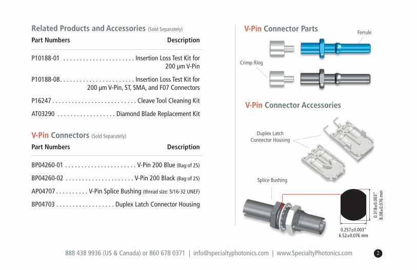
V-Pin Connectors (Sold Separately)
Part Numbers Description
BP04260-01 . . . . . . . . . . . . . . . . . . . . . . V-Pin 200 Blue (Bag of 25)
BP04260-02 . . . . . . . . . . . . . . . . . . . . . V-Pin 200 Black (Bag of 25)
AP04707 . . . . . . . . . . V-Pin Splice Bushing (thread size: 5/16-32 UNEF)
BP04703 . . . . . . . . . . . . . . . . . . Duplex Latch Connector Housing
888 438 9936 (US & Canada) or 860 678 0371 | [email protected] | www.SpecialtyPhotonics.com 2
Related Products and Accessories (Sold Separately)
Part Numbers Description
P10188-01 . . . . . . . . . . . . . . . . . . . . . . Insertion Loss Test Kit for 200 µm V-Pin
P10188-08. . . . . . . . . . . . . . . . . . . . . . . Insertion Loss Test Kit for 200 µm V-Pin, ST, SMA, and F07 Connectors
P16247 . . . . . . . . . . . . . . . . . . . . . . . . . . Cleave Tool Cleaning Kit
AT03290 . . . . . . . . . . . . . . . . . . Diamond Blade Replacement Kit
Crimp Ring
Ferrule
Splice Bushing
V-Pin Connector Accessories
V-Pin Connector Parts
0.31
8±0.
003”
8.08
±0.
076
mm
0.257±0.003”6.52±0.076 mm
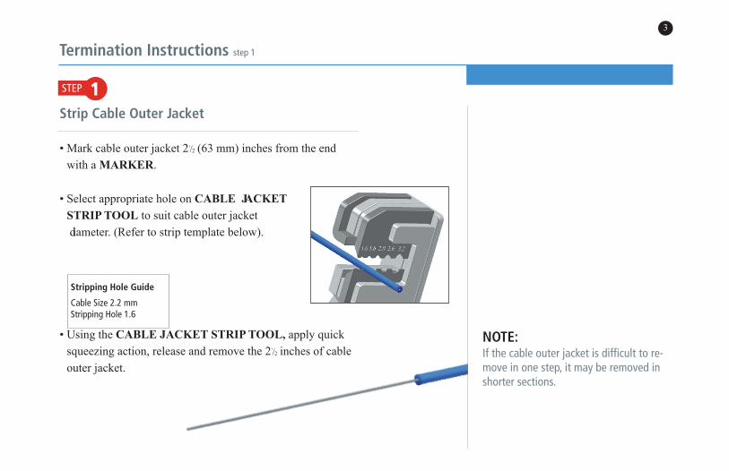
STEP 1
Termination Instructions step 1
Strip Cable Outer Jacket
• Mark cable outer jacket 21
/2 (63 mm) inches from the end
with a MarKer.
• Select appropriate hole on caBLe JacKet
strIP tooL to suit cable outer jacket
diameter. (Refer to strip template below).
• Using the caBLe JacKet strIP tooL, apply quick
squeezing action, release and remove the 21
/2 inches of cable
outer jacket.
NOTE:If the cable outer jacket is difficult to re-move in one step, it may be removed inshorter sections.
3
Stripping Hole Guide
Cable Size 2.2 mmStripping Hole 1.6

888 438 9936 (US & Canada) or 860 678 0371 | [email protected] | www.SpecialtyPhotonics.com
• Verify proper strip length against the strip template shown
below.
0" 1
/2" 1" 11
/2" 2" 21
/2" 3"
25 mm 50 mm 63 mm 76 mm
4
23
/16"
55.5 mm

STEP 2
Termination Instructions step 2
Install Crimp Ring
• Feed fiber through CRIMP RING. Bottom out the crimp
ring on the cable outer jacket using a clockwise turning mo-
tion. (i.e. screw the crimp ring onto the cable outer jacket if
necessary)
• Holding cable and crimp ring in left hand and CRIMP TOOL
in right, insert small end of crimp ring completely into the
front die nest of the crimp tool.
5
888 438 9936 (US & Canada) or 860 678 0371 | [email protected] | www.SpecialtyPhotonics.com 6
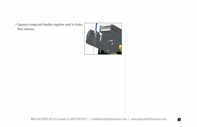
• Squeeze crimp tool handles together until it clicks,
then releases.

NOTE:If unable to insert buffered fiber throughguide tube, trim tip of the fiber usingscissors. If a short length of cable isbeing terminated, wrap the cable aroundyour finger to prevent fiber from pullingout of cable jacket.
Termination Instructions step 3
STEP 3Strip Fiber Buffer
Before you start:Make sure to use the appropriate strip tool insert for thebuffer removal process: White blade inserts
Be careful while handling the FIBER STRIPPER. Handle as a precision device and do not strike on hard surfaces or drop.
Be sure to clean blades frequently using small bristle brushsupplied.
IMPORTANT: Pull straight when stripping the fiber buffer. TheHCS fiber cladding can be damaged if fiber is not pulledstraight.
• Insert the buffered fiber through
the guide tube of the fiber stripper
until the cable outer jacket
bottoms out in the tube.
7
!
888 438 9936 (US & Canada) or 860 678 0371 | [email protected] | www.SpecialtyPhotonics.com
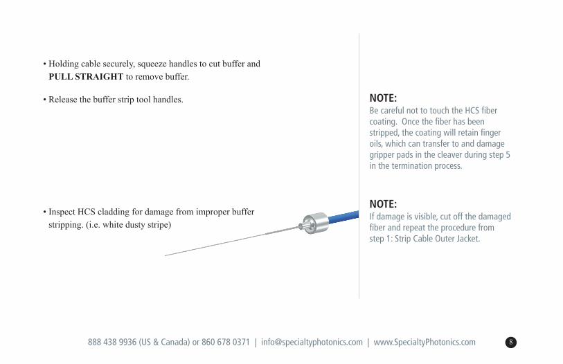
• Holding cable securely, squeeze handles to cut buffer and
PULL straIGHt to remove buffer.
• Release the buffer strip tool handles.
• Inspect HCS cladding for damage from improper buffer
stripping. (i.e. white dusty stripe)
NOTE:Be careful not to touch the HCS fibercoating. Once the fiber has beenstripped, the coating will retain fingeroils, which can transfer to and damagegripper pads in the cleaver during step 5in the termination process.
NOTE:If damage is visible, cut off the damagedfiber and repeat the procedure from step 1: Strip Cable Outer Jacket.
8
Termination Instructions steps 4 & 5
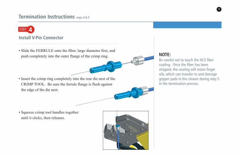
STEP 4Install V-Pin Connector
• Slide the FERRULE onto the fiber, large diameter first, and
push completely into the outer flange of the crimp ring.
• Insert the crimp ring completely into the rear die nest of the
CRIMP TOOL. Be sure the ferrule flange is flush against
the edge of the die nest.
• Squeeze crimp tool handles together
until it clicks, then releases.
9
NOTE:Be careful not to touch the HCS fibercoating. Once the fiber has beenstripped, the coating will retain fingeroils, which can transfer to and damagegripper pads in the cleaver during step 5in the termination process.
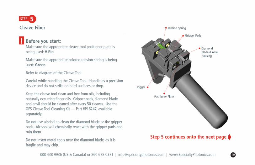
Tension Spring
Gripper Pads
Diamond Blade & AnvilHousing
Positioner Plate
Trigger
888 438 9936 (US & Canada) or 860 678 0371 | [email protected] | www.SpecialtyPhotonics.com 10
STEP 5
!
Step 5 continues onto the next page Á
Cleave Fiber
Before you start:Make sure the appropriate cleave tool positioner plate isbeing used: V-Pin
Make sure the appropriate colored tension spring is beingused: Green
Refer to diagram of the Cleave Tool.
Careful while handling the Cleave Tool. Handle as a precisiondevice and do not strike on hard surfaces or drop.
Keep the cleave tool clean and free from oils, including naturally occurring finger oils. Gripper pads, diamond bladeand anvil should be cleaned after every 50 cleaves. Use theOFS Cleave Tool Cleaning Kit — Part #P16247, available separately.
Do not use alcohol to clean the diamond blade or the gripperpads. Alcohol will chemically react with the gripper pads andruin them.
Do not insert metal tools near the diamond blade, as it isfragile and may chip.

Termination Instructions step 5 continued
STEP 5Cleave Fiber continued
• Holding the CLEAVE TOOL in a horizontal po-
sition, grip the handle while leaving your index
finger free to actuate trigger.
• Place the ferrule into the hole of the positioner
plate until it is fully inserted.
• Release the connector in the tool.
11
NOTE:It is critical to fully insert the connectorinto the positioner plate. Failure to do so,may cause poor cleave quality and/ordamage to the diamond blade.
NOTE:Do not hold onto the connector duringthe cleave process. Doing so may causepoor cleave quality.
DiamondBlade
Anvil
Connector
(Diagram pictured vertically to show detail)

888 438 9936 (US & Canada) or 860 678 0371 | [email protected] | www.SpecialtyPhotonics.com 12
• Using index finger, slowly and gently depress trigger to per-
form the cleave process. The cleave process is complete
when the fiber snaps away from the connector. Do not re-
lease the trigger!
• Before releasing the trigger, remove the connector from the
cleave tool and grasp the top of the scrap fiber while releas-
ing the trigger. Gently remove the scrap fiber while keeping
it away from the diamond blade.
• Dispose of scrap fiber safely in a hard-sided container.

Termination Instructions step 6
STEP 6Assemble Duplex Latch
Before you start:For use with OFS’ V-Pin in a zipcord configuration, for fiber or-ganization and increased connector-to-device retention.
To ensure polarity of the assembly, use the printing on the zipcord cable for leg identification.
Cable Exiting Straight Out of the Rear of the Duplex Latch
• Prior to assembly into the duplex latch, the connectors should
be terminated to the exact same length.
• Insert transmit and receive connectors
into the bottom portion of the
DUPLEX LATCH. Transmit is usually identified in the duplex latch
as #1 and receive is identified as #2.
!
13

888 438 9936 (US & Canada) or 860 678 0371 | [email protected] | www.SpecialtyPhotonics.com
• Press jacket material into the cable channels.
• Place top (latching) portion of housing over the connector as-
sembly and snap together.
14
Step 6 continues onto the next page Á
Termination Instructions step 6 continued
STEP 6
15
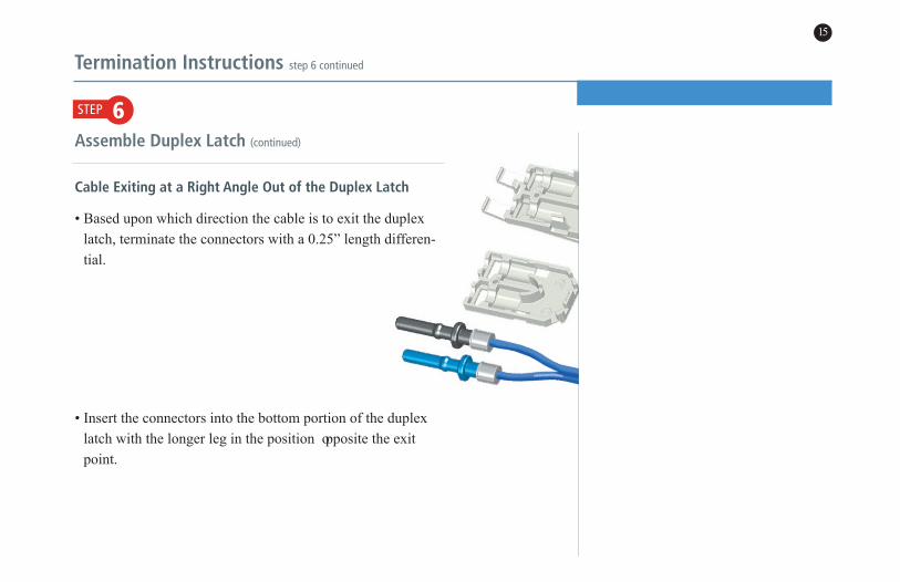
Assemble Duplex Latch (continued)
Cable Exiting at a Right Angle Out of the Duplex Latch
• Based upon which direction the cable is to exit the duplex
latch, terminate the connectors with a 0.25” length differen-
tial.
• Insert the connectors into the bottom portion of the duplex
latch with the longer leg in the position opposite the exit
point.

16
• Press the short leg cable material through the right angle
cable channel.
• Place top (latching) side of housing over the connector as-
sembly and press the longer leg into the upper duplex latch
half.
888 438 9936 (US & Canada) or 860 678 0371 | [email protected] | www.SpecialtyPhotonics.com

Maintenance & Trouble Shooting Guide
17
Importance of Cleave Tool Cleaning and Maintenance
The Cleave Tool supplied with OFS’s Termination Kits con-
tains movable parts, wear items, and a diamond blade that re-
quire regular maintenance, care, or replacement after useful
life in order to perform satisfactorily. Damage and parts re-
placement expense can result if recommended procedures are
not followed.
~ The diamond blade must be cleaned; the gripper pads must be cleaned,kept oil-free, and replaced after wear.
~ The cleave-tool trigger must be depressed slowly.
~ Fiber must be kept perpendicular to the diamond blade.
Cleave Tool Cleaning Kit
For cleaning your cleave tool, please order the OFS Cleave
Tool Cleaning Kit (part #P16247) which includes recom-
mended cleaning fluid, swabs, and complete instructions.
Diamond Blade Replacement Kit
For replacing the diamond blade/anvil assembly, please order
the Diamond Blade Replacement Kit (Part #AT03290.) The
kit includes a new diamond blade, anvil, replacement screws,
and complete instructions for performing this simple proce-
dure at your facility.

888 438 9936 (US & Canada) or 860 678 0371 | [email protected] | www.SpecialtyPhotonics.com 18
Poss
ible
Exp
lana
tions
Trouble Shooting Guide
Dim-light termination/ no light termination
Improper strip techniqueRefer to Steps 1 & 3
Improper crimp positionRefer to Steps 2 or 4 - 6
Poor cleave quality /High insertion loss
Improper crimp positionRefer to Steps 2 or 4 - 6
Improper cleave techniquesRefer to Step 5
Incorrect tooling for fiber size or connector typeRefer to Page 1
Diamond blade needs to becleaned or replacedRefer to Page 17
Gripper pads worn and need to be replacedCall Tech Support to place a
purchase order for service.
Fiber does not cleave
Fiber has not been first thoroughly strippedRefer to Step 3
Improper cleave techniquesRefer to Step 5
Incorrect tooling for fiber size or connector typeRefer to Page 1
Diamond blade needs to becleaned or replacedRefer to Page 17
Gripper pads worn and need to be replacedCall Tech Support to place a
purchase order for service.
Fiber protrudes or recesses after cleave
Improper crimp positionRefer to Steps 2 or 4 - 6
Improper cleave techniquesRefer to Step 5
Incorrect tooling for fiber size or connector typeRefer to Page 1
Gripper pads worn and need to be replacedCall Tech Support to place a
purchase order for service.
Prob
lem
If you are still experiencing problems, please call for Technical Support 888 438 9936 (US & Canada) or 860 678 0371

Termination and Test Kits Available
19
OFS offers a specialized Termination Kit—and
associated Insertion Loss Test Kit—for each type of
Crimp & Cleave connector we support. These kits are
available in various combinations of sizes and/or connec-
tor types. Customer Relations at our factory can help
you select the correct kit for your purposes.

This document is for informational purposes only and is not intended to modify or supplement any OFSwarranties or specifications relating to any of its products and services.
Copyright © 2013 OFS Fitel, LLC.All Rights Reserved.
0113
55 Darling Drive, Avon, CT 06001
To learn more, please call or visit our website.
Phone: 1 860 678 0371Toll Free: 1 888 438 9936Email: [email protected]: www.SpecialtyPhotonics.com
AP04266 Rev. K
Trademark Information:
Manufactured in the USA by OFS Specialty Photonics Division.
V-System is a registered trademark of OFS Fitel, LLC.
HCS is a registered trademark in the USA of OFS Fitel, LLC.


![Cleave and Rescue, a novel selfish genetic element and ...€¦ · synthetic selfish genetic element, CleaveR [Cleave and Rescue (ClvR)], that is simple to build and can spread a](https://static.fdocuments.in/doc/165x107/5eadf2998c5dc3507e3351c6/cleave-and-rescue-a-novel-selfish-genetic-element-and-synthetic-selfish-genetic.jpg)