You know you’re in the Zone™
59
You know you’re in the Zone™ You know you’re in the Zone™
-
Upload
southern-olson -
Category
Documents
-
view
30 -
download
0
description
You know you’re in the Zone™. ! WARNING !. GAS/VAPOR RELATVE SPAN Acetone50 Allyl alcohol50 Benzene44 Butane51 Butan-2-one (MEK)48 Butyl Acetate36 Cyclohexane44 Di n-butyl ether43 Ethane82 Ethanol64 Ethene81 Ethyl acetate46 Ethylbenzene30 - PowerPoint PPT Presentation
Transcript of You know you’re in the Zone™

You know you’re in the Zone™
You know you’re in the Zone™

Innovators in Gas Detection
M i c r o M a x P r oT r a i n i n g P r o g r a m

Innovators in Gas Detection
- DO NOT PROCEED BEFORE READING -
To ensure proper functioning and use of this product, do not use this instrument until you read and completely understand this operatingmanual. It contains operating and maintenance procedures to ensure proper instrument function. For your safety, you are required tocalibrate this instrument periodically. Please refer to the calibration section of this manual
WARNINGSubstitution of components may impair intrinsic safety.
WARNINGUse only MPRO-BPR NiMH rechargeable battery pack, or MPRO-BPA alkaline battery holder with four each of the following alkaline cellsonly! Duracell Procell-2400, Duracell MN-2400, and Eveready E-92 or EN-92. Observe proper polarity when installing alkaline batteries.
CAUTIONDo not change or charge batteries in a hazardous location.
CAUTIONThe lower explosive level range of this monitor is factory calibrated to methane. If monitoring a different combustible gas, calibrate thecombustible gas range of the monitor to the appropriate gas.
CAUTIONThis instrument has not been tested in atmospheres exceeding 21% oxygen.
CAUTIONCalibration is required when sensors are changed or added to the instrument.
WARNINGUse only the approved accessories indicated in this manual.
WARNINGDo not attempt datalogging functions in a potentially hazardous environment.
! WARNING !

Innovators in Gas Detection
1.0 Preparation for use1.10 Unpacking
Check for these items: Packaging (retain for possible future use) Instrument with internal rechargeable battery pack Calibration certificate Standard accessories:
AC battery charger Alkaline battery holder Dust filter 10 foot sampling hose with filter & water trap Rubber boot with belt & neck strap Instruction manual
1.11 ChargingCAUTION: Do not change or charge batteries in a hazardous location.Do not try to turn on or otherwise operate this instrument until it is fully charged.Use only the MPRO-1 A.C.charger, or the MPRO-2 220 volt A.C.charger, or theMPRO-6 vehicular charger. Use of any other charger may cause permanentinstrument damage and will void any warranties. The charge period is dependent onthe condition of the batteries, but should not exceed about four (4) hours for acompletely depleted battery pack. Partially depleted packs will be charged in a muchshorter period of time.
To commence charging, and with the charger supplied with ac power, connect thecharger plug to the instrument port (Fig.1-1) and instrument display should read“CHARGING BATTERY”. When charging is completed the charger turns itself off and“CHARGE COMPLETE” is displayed. The instrument is now fully charged and readyfor immediate use.If charging is attempted without the rechargeable battery, or with alkaline batteries,“CHECK BATTERY” is displayed.

Innovators in Gas Detection
F ig . 1 -1 C h a rg in g th e M ic ro M a x P ro
2 .0 G e n e r a l D e s c r ip t io n
T h e M ic ro M a x P ro is a p ro g ra m m a b le o n e , tw o , th re e , fo u r , o r w ith C o m b o -T o x s e n s o r, u p to f iv e g a sm o n ito r . I t c o m b in e s p ro v e n s e n s o r p e r fo rm a n c e a n d e le c tro n ic s in a s m a ll, l ig h tw e ig h t , a n d e a s y tou s e m o n ito r . I t u t i l iz e s a u s e r f r ie n d ly in te r fa c e a n d c o n s is ts o f th e m o n ito r , N iM H re c h a rg e a b leb a t te ry p a c k , b a tte ry c h a rg e r , ru b b e r b o o t w ith n e c k s tra p a n d b e lt c lip , d u s t f il te r , 1 0 fo o t s a m p lin gh o s e w ith f i lte r a n d w a te r t ra p , c a lib ra t io n c e r t if ic a te a n d in s tru c t io n m a n u a l.
P r io r to s h ip m e n t th e m o n ito r w a s c o n f ig u re d w ith d e fa u lt a la rm s a n d o th e r s e tt in g s te s te d a n dc a lib ra te d . A f te r c h a rg in g , it is re a d y fo r u s e .

Innovators in Gas Detection
L a r g e a l a r m L E D b a r
P o r t
B a t t e r y C o m p a r t m e n t O N / O F F S w i t c h M O D E R e a r V i e w
S w i t c hI n l e t
F i g . 2 - 1 M i c r o M a x P r o

Innovators in Gas Detection
3.0 FEATURES
3.10 Liquid Crystal DisplayHigh contrast 4 line by 16 character alphanumeric display. Indicates gas concentration of up to four gasessimultaneously.
3.11 Display BacklightingAutomatic fiber-optic backlight provides display readability in dim or dark environments.
3.12 Automatic toxic sensor recognitionMicroprocessor automatically recognizes toxic sensors when plugged in. Monitor displays corresponding gas, setsgain, correct alarm levels and initializes temperature compensation.
3.13 User selectable power sourceUser has option of powering instrument either with the supplied NiMH rechargeable battery pack or with four “AAA”alkaline cells (use only the cells that are approved for use), mounted in the supplied battery holder.
3.14 User friendly interface User friendly interface is intuitive for ease of use and simplicity of operation.
3.15 Extensive Programming optionsThere is a wide range of programming options including a supervisory mode to “custom taylor” the instrument toyour needs.
Innovators in Gas Detection
3.16 Programmable gas alarms High & low alarm levels, TWA mode for toxics, latching or non-latching, are all user programmable.
3.17 Fully automatic calibrationFast, easy, accurate calibration that requires no user adjustments or tools.
3.18 Confidence beepUser selectable ‘confidence’ beep provides an audible beep about every 20 seconds toreassure user that the instrument is operating.
3.19 Voice & display messagingWith this option, user may select English, Spanish, French or German as the language of choice. If thevoice option is disabled, the chosen language will still be indicated on the display.
3.20 Battery GaugeInstrument continuously displays a battery bar graph. 6 full bars indicate a fully charged pack. If instrumentis powered by alkaline batteries, battery voltage, not bar graph, is indicated on the display.
3.21 Pump or Diffusion mode of operationUser may choose pump or diffusion mode of operation. If pump is selected ‘P’ is displayed and all thebenefits of internal pump operation are available. In diffusion mode ‘D’ is displayed. If pump mode isselected and pump fails, instrument automatically switches to diffusion mode for continuous operation andprotection.
Innovators in Gas Detection
3.22 Real Time clockUser settable real time clock provides continuous time display. If daylight savings time is selectedthe time will be automatically updated.
3.23 User selectable calibration gas concentrationThis feature allows user to select the desired calibration gas concentration, within specified limits, forall sensors except Oxygen.
3.24 User selectable LEL conversion factorsThis feature allows instrument to accurately indicate the LEL level for a wide range of hydrocarbonsafter calibration with methane gas.
3.25 Multiple gas alarm indicatorsAudible and visual alarms alert user of unsafe gas levels
3.26 Low flow alarmIn pump mode, a steady audible alarm is accompanied by a visual alarm. Display indicates “LowFlow Alarm.” If alarm persists, instrument will indicate “PUMP FAIL” and switch to diffusion mode ofoperation.
3.27 RFI Resistant DesignHigh resistance to radio frequency interference minimizes false alarms.
3.28 Charge Status RecognitionAutomatically shuts instrument off if charger is connected while monitor is on. This prevents thecharger from being used as a power source, which is not intrinsically safe. When the charger isconnected, display will indicate “CHARGING BATTERY”.

Innovators in Gas Detection
3.29 Calibration RecordUser selectable “Last Calibration Date” and or “Calibration Due Date” display on start-up
3.30 Peak, STEL & TWAMode function enable displays of Peak (highest toxic or combustible and lowest Oxygenlevels), STEL (15 minute accumulated short-term exposure level) and TWA (8 houraccumulated time weighted average), since instrument was last turned on. The STELand TWA will be indicated only if the “TWA ALARMS” mode is turned on.
3.31 Low Battery WarningDual beep every 15 seconds provides low battery warning 15 to 30 minutes prior toshutdown. With alkaline batteries, low battery warning occurs at 4.2 volts.
3.32 Intrinsic SafetyThe MicroMax Pro is classified by Underwriters Laboratories for intrinsically safeoperation in Class I, Division I, groups ABCD, Class II, Division I, groups EFG and classIII hazardous locations. Other approvals are pending.
3.33 DataloggingThe MicroMax Pro is supplied with datalogging capabilities and all necessary hardware,cables and software. This feature provides from 40 to 200 hours of “wrap around” datastorage
Innovators in Gas Detection
4.10Turn-on
After charging the NiMH battery pack, or installing fresh alkaline cells, turninstrument on, in clean air, by depressing the on/off button until a confirming“beep” is heard. Release the on/off button and instrument will display thesoftware version number and “ON”, before cycling through its turn-onsequence (See fig.4-1 above for the default turn-on sequence). The turn onsequence in fig. 4-1 is self explanatory: after “ON” instrument goes through“Testing”, “zeroing” cycles before displaying the last calibration date, low alarmlevels, high alarm levels, briefly indicate whether the voice function isactivated, and go into normal operating mode. In normal operating mode gasreadings and levels occupy the first two lines, ”READY” on the third line, andon the fourth line the number of hours of run time remaining, “P” or “D”, forpump or diffusion mode of operation respectively, and the current time. Ifinstrument is powered by alkaline batteries, battery voltage, and not hours ofrun time remaining, is displayed. With Alkaline batteries, voltage should beabout 5.8 volts with fresh batteries. Low battery warning occurring at 4.2 volts.
Innovators in Gas Detection
4.11 Standard Mode Sequence
Each standard mode sequence is available by depressing the mode buttonsequentially.PEAK READINGS. The highest toxic and combustible gas levels and the lowestoxygen levels. Depressing the on/off button while in this mode will clear peak values.STEL READINGS. Accumulated short-term exposure limit values for toxic gases aredisplayed only if “TWA” is turned on. (Please refer to paragraph 6.23 below).AVG READINGS. Accumulated time weighted average values for toxic gases aredisplayed only if “TWA” is turned on. (Please refer to paragraph 6.23 below).USER SETUP. This mode provides a wide range of programming options and is fullydetailed in Appendix D. In addition to calibration (paragraph 5.11), it allows memory tobe cleared, and pump, voice and confidence beep functions to be turned on or off. Toenter the user setup mode depress the on/off button when line 3 of display indicates“USER SETUP”. To accept each default standard mode setting depress the modebutton. To change pump, voice, or confidence beep from “on” to “off” or vice versa,depress the on/off button when the appropriate menu item is displayed.READY. This is the normal operating mode. Instrument is now ready for use.

Innovators in Gas Detection
4.12 Test Sensors & AlarmsIt is recommended that proper alarm function be verified prior to use by applying calibration or alarmcheck bump gas. Alarm check gas (Test 1A) should be used only for instruments which contain one ormore of the four (4) standard sensors (O2, LEL, CO or H2S). For other configurations use calibrationgas with instrument in normal operating mode. After testing, remember to clear the peak values, or ifTWA alarms are “on”, clear memory. Test low flow alarm by placing finger over inlet when in pumpmode. If instrument does not go into low flow alarm when inlet is blocked, instrument should beoperated in diffusion mode after entering the “USER SETUP” mode and changing the pump statusconfiguration to “PUMP OFF”. Instrument should be serviced as soon as possible to fix the problem.Instructions for using alarm check gas (part no. Test 1A)
Turn monitor on in fresh air and allow to go into normal operating mode. Break shipping tab off canister. Attach blue balloon on to black disk on Alarm Check Gas hose. Insert red end of hose into hole in canister nozzle. Place finger over the end of the hose (or pinch hose) and pulse trigger so that gas fills the balloon to its
natural shape. Do not over-inflate balloon. Insert other end of hose into air intake. All channels should be in alarm for a few seconds while gas passes over sensors. Check display to
confirm proper operation of visual alarms for each gas. Confirm proper operation of visual and audiblealarms.
Remove hose from monitor and allow alarm check gas to be purged from monitor with fresh air. Clear Peaks or, if TWA alarms are “on”, clear memory
Innovators in Gas Detection
4.13Continuous monitoringIt is highly recommended that the supplied dust filter (part # 16PFC) be attached at all times, when inpump mode, if the instrument is being used in a dusty environment. Keeping dust out increasesinstrument life while lowering maintenance costs.
4.14 Remote Sampling (Pretesting)Remote areas and confined spaces may be sampled in pump mode prior to entry by connecting thesupplied 10-foot or longer sampling hose to the inlet fitting. The 10 foot, or longer, sampling hose isusually used for pretesting. Continuous monitoring with the sampling hose attached will reduce thenumber of hours of run time available.The following procedure is recommended:
Turn instrument on and allow to enter normal operating mode. Be sure you are in “PUMP” mode. (“P” indicated in center of line 4 of display). Test alarm function with gas as indicated above. Test low flow alarm as indicated in paragraph 4.11 above. Connect sampling hose to instrument. Place hose in area to be sampled. Wait two minutes for full response. Take readings Retrieve hose and disconnect from instrument
Hose lengths up to 100 feet may be used for pre-testing. Add one second per foot to the two-minutewait for full response.

Innovators in Gas Detection
4.15 Alarms
Appendix F provides details of the various alarm modes. In the event of a gas alarm,evacuate the area immediately. Investigate the cause of the alarm only when you aresafely out of the potentially hazardous area. The gas and level that generated the alarmcan be indicated by accessing the “Peak” mode function.
A “warning” low gas alarm indicates a gas concentration above the low alarm set-point and isindicated by 3 beeps from the horn, flashing LED, flashing gas range of the sensor in alarm,and display of the word “WARNING.” Voice will also indicate “WARNING” except for O2,which will be indicated by “DANGER.”
A “danger” high gas alarm indicates a gas concentration above the high alarm set-point andis indicated by 3 beeps from the horn, flashing LED, flashing gas range of the sensor inalarm, and display of the word “DANGER.”
Low flow alarm is indicated by a continuous audible alarm, flashing LED, and the words“LOW FLOW” displayed
Low battery alarm is indicated by 2 short beeps from the horn every 15 to 20 seconds,together with the words “LOW BATTERY’ on the display. It occurs 15 to 30 minutes prior tobattery-depleted alarm and shutdown.
Battery depleted alarm is indicated by 5 audible beeps, display of “BATTERY DEPLETED”and shutdown.

Innovators in Gas Detection4.16 Clear Memory
Memory is automatically cleared after each calibration.To clear memory manually:
Depress the mode button repeatedly until “USER SETUP” is displayed. Depress the on/off button to enter the user setup mode. Depress the mode button four (4) times until “CLEAR MEMORY” is displayed. Depress the on/off button once to simultaneously clear memory and return to
normal operating mode.
4.17 Turn off
To turn the MicroMax Pro off, depress and hold the on/off button, andinstrument will beep 4 times. After the 4th beep, release the button, andinstrument will indicate “POWER OFF” and automatically turn itself off.CAUTION: If on/off button is released during countdown, instrument will resumenormal operation.

Innovators in Gas Detection
5.0 CALIBRATION

Innovators in Gas Detection5.0 CALIBRATION
5.10 Calibration frequency It is important to verify accuracy on a regular basis to guard against any unexpected loss of
sensitivity due to mechanical damage, immersion, aging, or exposure of the sensors topoisons (such as high concentrations of combustible gas, tetra-ethel-lead, sulfides or siliconecontaining lubricants) present in the atmosphere being monitored.
The safest possible course of action is to expose the sensors to a known concentration testgas before each day’s use. This “bump” test takes only a few seconds to accomplish. It is notnecessary to make a calibration adjustment unless readings are off by more than 15% of theapplied gas concentration. If this procedure is followed, the calibration interval can be up to90 days.
If your calibration procedures do not permit daily checking of the sensors, Lumidorrecommends the following procedure to establish a safe and prudent check schedule.Initially, over a period of a few days, check the response daily to be sure there is nothing inyour atmosphere that is poisoning the sensors. If the instrument displays correctconcentration levels after two (2) weeks on this schedule, the calibration interval may beextended to two weeks. If the instrument do not require calibration, after two (2) months onthis schedule, the calibration interval may be extended to thirty (30) days. WARNING: Thisdoes not preclude testing with gas on a regular basis.

Innovators in Gas Detection
5.11 Calibration procedure (when all calibration gases are in a single canister)
CAUTION: Calibration should be carried out only in a clean air environment, known to befree of contaminants.CAUTION: Be sure the calibration gas is within the expiration date indicated.
Use mode button to scroll through mode functions to “user setup.” Depress on/off button to enter “user setup”. Use mode button to scroll to “calibrate?” Depress on/off button to enter the calibration mode. Follow instructions on instrument’s display. Instrument will first complete a “zeroing” countdown from to zero (0) Apply calibration gas when “apply gas” is displayed.(Fig.5-1) Instrument will display “calibrating” and count down to zero (0) When “cal complete” is displayed, observe that all sensors calibrated are displayed below
“cal complete”. Remove gas and turn off gas flow. Instrument will go into a “Purging” countdown to zero (0) After purging, instrument automatically clears Peak, TWA and STEL values, so it is not
necessary to manually clear memory. This calibration process is now complete.
Innovators in Gas Detection
5.12 Calibration procedure (not all calibration gases are in a single canister)CAUTION: Calibration should be carried out only in a clean air environment, known to be free of contaminants.CAUTION: Be sure the calibration gas is within the expiration date indicated.
Use mode button to scroll through mode functions to “user setup.” Depress on/off button to enter “user setup”. Use mode button to scroll to “calibrate?” Depress on/off button to enter the calibration mode. Follow instructions on instrument’s display. Instrument will first complete a “zeroing” countdown to zero (0) Apply the first calibration gas, or gases, when “apply gas” is displayed.(Fig.5-1) Instrument will display “calibrating” and count down to zero. When “cal complete” is displayed, observe which sensors are calibrated and displayed below “cal complete”. Remove
gas and turn off gas flow. Depress the on/off switch and instrument will display “Apply gas” Apply the second calibration gas Instrument will display “calibrating” and count down to zero. When instrument displays “cal complete”, observe whether all sensors are calibrated and displayed below “cal
complete”. Remove gas and turn off gas flow. If all sensors were displayed below “cal complete”, instrument will display “Purging”, count down to zero, clear memory and
the calibration process is complete. If a third calibration gas needs to be applied, after instrument displays “cal complete”, depress the on/off button and follow
the instructions on the display. When “cal complete” is displayed, remove gas and turn off gas flow. Instrument will purge itself while counting down to zero, and clear memory. The calibration process is now complete.

Innovators in Gas Detection
5.13 Zeroing the MicroMax Pro
CAUTION: Zeroing should be carried out only in a clean air environment, knownto be free of contaminants.There are three ways to zero the instrument:
Zeroing is done, automatically, each time the instrument is calibrated.
Zeroing is done, automatically, each time the instrument is turned on if the “AUTOZERO” feature is selected in the supervisory mode. Please refer to paragraph6.15 below.
Zeroing may be done manually without doing a full calibration by entering thecalibrating mode (please refer to paragraph 5.11 above) and, anytime while theinstrument is zeroing and counting down from thirty (30) seconds to zero (0),depress and hold down the mode button for at least three (3) seconds. Thisprocedure will complete zeroing and exit the calibration mode.

Innovators in Gas Detection
6.0 PROGRAMMING THE MICROMAX PRO

Innovators in Gas Detection
6.10 Programming Options
Powerful programming options allow user to customize the instrument in accordance withhis organization’s safety policy. Some options are available in the user setup mode(Appendix D) but the majority of these options are available only in supervisory mode(Appendix E). ALL PROGRAMMING OPTIONS CAN ALSO BE ACCOMPLISHEDTHROUGH THE MAXPRO SOFTWARE, USING THE UPLOAD FUNCTION. THIS IS BYFAR THE MOST CONVENIENT AND EFFICIENT METHOD AND IS STRONGLYRECOMMENDED IN ALL CASES WHERE A COMPUTER IS AVAILABLE (For uploadingprocedures please refer to paragraph 7.17 below). To enter the supervisory mode depressand hold the mode button for five (5) seconds, during the “TESTING” phase of the start-upsequence. The general structure of the supervisory mode is to depress the mode button tobypass an option, or use the on/off button to select and enter the option’s menu. Where amenu has two options only, (for example “on” or “off”), depressing the on/off switch oncesimultaneously accomplishes three functions; entering the menu, changing the option andexiting the menu.The following are all programmable.
Innovators in Gas DetectionThe following are all programmable:
LEL gas type Date format Date/Time Daylight saving time Datalog frequency Auto-zero during start-up sequence Display last calibration date displayed during start-up sequence Latching or non-latching alarms Calibration gas level High alarm set-points Low alarm set-points Calibration due date displayed during start-up sequence Calibration due frequency Language choice TWA alarm choice Return to default settings. Jump to calibration mode

Innovators in Gas Detection6.11 Select LEL gas type
The LEL sensor is designed to detect a wide range of combustible gases withinherently different characteristics. To obtain the most accurate results it isnecessary to calibrate with the target gas, or a gas with similar characteristics.This programming option allows user to calibrate with methane but obtain gasreadings equivalent to Methane, Pentane, Propane, Hexane or Xylene.Appendix A, paragraph M, provides data on the relative span of many commoncombustible gases. The relative span for each of these gas options is as follows:Methane100Propane 63Pentane 50Hexane 46Xylene 31From these five gases, select the one with a relative span value closest to therelative span of your target gas. For example, if your target gas is benzene(relative span 44 per Appendix A, paragraph M), select Hexane whose relativespan of 46 is closest to that of benzene. To program the instrument, enter thesupervisory mode (6.10 above) and depress the on/off button to enter the“Select LEL GAS TYPE” menu. Use the mode button to select the gas type andthe on/off button to exit this menu sequence.

Innovators in Gas Detection
6.12 Setting the Date format
The default date format is the MM/DD/YYYY (MONTH/DAY/YEAR) as iscustomary in the USA. To accept the default format, enter the supervisory mode(para.6.10) and use the mode button to scroll down to “DATE FORMAT”.Depress the on/off button once to accept the format. If there is no reason tochange the date or time, depress the on/off button a further twelve times to exit.To change the date format to DD/MM/YYYY, enter the supervisory mode(par.6.10 above) and use the mode button to scroll down to “DATE FORMAT”.Depress the on/off button twice to change the format. If there is no reason tochange the date or time depress the on/off button a further twelve times to exit.

Innovators in Gas Detection
6.13 Setting date & time.Please refer to the Supervisor menu flowchart in appendix E. To set correct valuesfor time and date, first enter the supervisory mode (par.6.10 above) and use the mode button to scroll to“DATE FORMAT”. Depress the on/off button to enter the menu. Depress the mode button. The firstdigit on the left will start to flash. Depress the on/off switch to accept the flashing number and move onenumber to the right or use the mode button to change the flashing number to the desired value. If theUnited States format of MM/DD is chosen this is the first month digit and must be either a 0 or a 1. Letus set the date to September 2, 1999. We need 09 for the two-month digits. If 0 is flashing, depress theon/off switch. This accepts the 0 on the left and we may now use the mode switch to set the nextnumber to 9. Depress the on/off button to accept the 9 and the month is correctly set to 09. The nextdigit on the right is now flashing and the mode button is used to select 0. Depress the on/off button toaccept the 0, the mode button to select 2, and the on/off button to accept to accept 2. To set the year,use the mode button to select 1, the on/off button to accept the 1. Use the mode button to select the 9and depress the on/off button to accept. Use the mode button to select 9 again and depress the on/offbutton to accept. Use the mode button to select the final 9 and the on/off button to accept. Thiscompletes the date settings. To continue and set the correct time to 14.45 (2.45PM), use the modebutton to select 1 and the on/off button to accept the 1. Use the mode button to select 4 and depressthe on/off button to accept the 4. Use MODE switch to select 4 and depress the ON/OFF switch toaccept the 4. Use mode to select 5 and on/off to accept and exit this menu. The date and time are nowcorrectly set. The “Day Light Saving” time menu now appears. Default is “off”. Depress the mode buttonto accept this setting and exit or depress the on/off button to change the setting and exit.

Innovators in Gas Detection
6.14 Datalog frequencyThe datalog frequency is the time interval between readings displayed by the histogram, and may beset at 1, 2, 3, 4 or 5 minutes. The time internal does not affect the total number of data points. The totalnumber of data points is fixed at 2400 so if a one-(1) minute interval is chosen 40 hours of data may bedisplayed. If a five (5) minute interval is chosen 200 hours of data may be displayed. The default settingis one (1) minute so no action need be taken if this interval is acceptable.To set or change the datalog frequency, access the supervisory mode (par. 6.10 above) and use themode button to scroll down to “Data Log-freq.” Depress the on/off button to enter the menu sequence,then use the mode button to select 1,2,3,4 or 5-minute interval. Depress the on/off button to accept theselection and exit.
6.15 Auto-Zero during start-up sequenceAs it comes from the factory auto zero is done during the calibration procedure. However, auto zeromay be programmed to operate on start-up each time the instrument is turned on. The important thingto bear in mind is that auto zero must be done in clean uncontaminated air, regardless of when it isdone.
If auto zero during start-up is desired enter the supervisory mode (par.6.10) and use the mode button toscroll down to “Auto Zero Mode.” Auto zero will be displayed together with “off”. Depress the on/offbutton once to toggle from “off” to “on and exit.
Innovators in Gas Detection
6.16 Display last calibration date during start-up sequence
The Last calibration date is automatically displayed in the start-up sequence. If this is not desired it isnecessary to reprogram the instrument. Access the supervisory mode (par.6.10 above) and use themode button to scroll down to “Display Last Cal”. Depress the on/off button once to toggle from “on” to“off” or “off” to “on” and exit.
6.17 Latching or non-latching gas alarms
The default setting is non-latching alarms (latching alarm “off”). This means that the instrument willcease alarming when gas levels fall below the alarm setpoints. If latching alarm (latching alarm “on”) ischosen instrument will continue to alarm when gas levels fall below alarm setpoints and may be turnedoff only when the user depresses the on/off button. To change from latching alarm “off” to latchingalarm “on”, enter the supervisory mode (par.6.10 above) and use the mode button to scroll down tolatching alarm. Depress the on/off button once to make the change and exit the menu.

Innovators in Gas Detection
6.18 Calibration Gas Level
The defaults, as well as the full range of programmable calibration gas levels,are set out in table A, paragraph P, of Appendix A. If it is desired to change thedefault levels, enter the supervisory mode (par.6.10 above) and use the modebutton to scroll down to “Cal Gas Level”. Depress the on/off button to selectthe LEL. If the displayed cal gas level is acceptable depress the on/off button toaccept and move to the next gas. If a change in LEL cal gas level is desired usethe mode button to set the level in 5% LEL increments in the range 5% LEL to55% LEL. To set the calibration gas level for carbon monoxide (toxic A), depressthe on/off button and CO is selected. Either depress the on/off button to acceptor use the mode button to set the calibration gas level, in 5ppm increments, tothe desired value in the range 50ppm to 300ppm. Depress the on/off button toselect H2S (or other gas in toxic B). Depress the on/off button to accept the leveldisplayed or use the mode button to set the desired value, in 5ppm increments,in the range 5ppm to 25ppm. To exit the menu, depress the on/off button.

Innovators in Gas Detection
6.19 High alarm set
The defaults, as well as the full range of programmable high alarm setpoints, are set out inparagraph J of appendix A. To change the default levels, use the mode button to scrolldown to “High Alarm Set” and use the on/off button to select the gas (e.g. Oxygen) forwhich the alarm is being set. If the alarm level displayed is acceptable, depress the on/offbutton to accept and select the next gas. If a change in value is desired use the modebutton to change the high alarm setting to the desired value. Depress the on/off button toselect the next gas (LEL). If the value displayed is acceptable depress the on/off button toaccept and select the next gas. If a change in value is desired use the mode button to setthe desired alarm level. Follow this same procedure for the other gases and depress theon/off button to exit this menu.
6.20 Low alarm set
The defaults, as well as the full range of programmable high alarm setpoints, are set out inparagraph J of appendix A. To change the default levels, use the mode button to scrolldown to “Low Alarm Set” and depress the on/off button to simultaneously enter the menuand select the first gas. The procedure for low alarm set is identical to that for high alarmset in para. 6.19 above, to which reference should be made.
Innovators in Gas Detection
6.21 Auto display of “Calibration due”
The default setting is “off”. If it is desired that instrument display “calibration due” during the start-upsequence enter the Supervisory mode (par.6.10 above) and use mode to scroll down to “cal. due auto”.Depress the on/off button once to change “CAL. DUE AUTO” to “on.” The “cal due freg.” screen willappear. Use the mode button to select a frequency of 01 to 90 days and depress on/off to accept andexit.
6.22 Language Set
The default language is English. If a change to another language is desired, enter supervisory mode(par.610 above) and use mode to scroll down to “LANGUAGE SET” To enter the menu, depress theon/off button and use mode to select English, Spanish, French or German. Depress on/off to accept theselection and exit the menu.
6.23 TWA Alarm set
Default is “off” so if TWA alarm is desired enter supervisory mode (par.6.10) and use mode to scrolldown to “ALARM TYPE”. Depress on/off to change the TWA setting to “on” and exit the menu.
Innovators in Gas Detection
6.24 DEFAULTS?
This option allows return to all supervisory mode default settings. To accept alldefault settings and return to the start of the supervisory mode, depress on/offbutton. To bypass this option depress the mode button. The purpose of thisoption is to allow a user who is unhappy with his selections to start over from thebeginning of the supervisory mode.
6.25 CALIBRATE?
This option allows calibration in the supervisory mode. To bypass, depress themode button. To calibrate follow the calibration procedure in paragraph 5.11above.

Innovators in Gas Detection
7.0 Datalogging (WARNING: Do not attempt datalogging functions in a potentially hazardousenvironment).
7.10. System requirements: IBM PC or compatible system 486 or higher 550 megabyte hard drive 8 Meg of RAM EGA, VGA, SVGA, or XVGA video card Windows 95 or higher or windows NT 3.5 (1.44mb) Floppy disk drive (1) free RS232 serial port
7.11 General information: The MPRO-LOG program provides the tools necessary to transfer, save and recall, (for viewing and/or
printing), the data recorded in the MicroMax Pro. It is a full function program that does not require anadditional database program.
It consists of four (4) 3 ½” floppy discs. One is the program disc with installation instructions and the otherthree are “DAO” drivers which will not be required in many installations and should be loaded only ifprompted so to do by on-screen instructions.

Innovators in Gas Detection
7.12 Program Installation Place the program disk in the 3 ½” high intensity drive (drive X). In most cases this will be drive A. From the start menu select “run”, type X:/SETUP. (In most cases this will be A:/SETUP) and click “ok” Follow on-screen instructions 7.13 Starting the program: Go to Windows Explorer and locate the MaxPro folder (start\program files\explorer). Double click on
“program files” in the “all folders” screen on the left. Double click on “MaxPro.” This brings up the “contentsof c:\program files\maxPro” screen on the right. Double click on “MaxPro.exe” to bring up the program.
Connect the RS232 end of the supplied download cable to an available “COM” port on your computer. Click on “TRANSFER” and the following drop down menu appears: TRANSFER
Download Data Download Configuration/Alarm Levels Upload Configuration/Alarm Levels Modify Instrument Parameters Set Default Alarm Levels Store Default Alarm Levels Data Recovery File Import Select Port/Time Zone Print Setup
Exit
Click on (or arrow down on the menu and press<enter>) "select port/time zone". This will display thecomm. port and time zone selections menu. Select theappropriate
Comm. port (make sure your port selectionagrees with the comm. port on your computer towhich the download cable connected) and timezone. Click on "ok"
(or press <enter>) and you will be returned tothe transfer menu.

Innovators in Gas Detection
7.14Downloading the MicroMax Pro
Turn on instrument and allow to go into normal operating mode. Click on “Transfer” and the transfer menu appear. Click on "download data" and the following will appear on the screen: "Is cable
connected and instrument ready?", "yes" "no". Connect the instrument interface end of the download cable to the port of the
instrument (Fig.2-1). Click on "yes" or press <enter>. Instrument will start to count up. This count
should also be taking place on the computer screen. When all data has been transferred, instrument displays "data sent " and shuts
itself off. When the computer displays "transfer complete", click "ok" or press<enter>.
Type your "last name", "first name" and "location", when prompted so to do.A three-(3) digit numerical code (eg.100) is generally used for "location", butthe important thing to bear in mind is that the location code should notexceed 10 characters. Click on "ok".
Wait a moment while computer stores the information.

Innovators in Gas Detection
7.15 Displaying/printing data
Click on "display", and then "file open". A list will appear of all stored files; clickon the desired employee name to highlight, then "ok" to display "peaks,averages and alarms”
Data relating to the file selected is displayed as shown in Fig. 7-1 above. To display a detailed histogram, click on "view", then on "histogram" and stored
data will be displayed at one-minute intervals. Note that the histogram isseparated into groups. Each time the instrument is turned on represents aseparate group. To print the histogram, click on "view", then on "print"
To display the graphs, click on "view" then on "graphs." A group of up to fourcurves, (depending on monitor type) will be displayed (See Fig.7-3 below). Toprint the graphs click on "graphs", then on "print". CAUTION: if any group is lessthan 15

Innovators in Gas Detection
7.16 Uploading Uploading is the process of transferring information from a computer to the instrument. Upload
utilities provide the ability to set date and time in the instrument, as well as modify operatingparameters such as any of the variables in the “USER SETUP” or “SUPERVISOR” modes.
The upload utilities consist of four (4) menu selections in the transfer menu. “Upload configuration alarm levels”“Modify instrument parameters”“Set default alarm levels”“Store default alarm levels”
Before uploading to an instrument, be sure that the time zone and comm. port are correct. This isaccomplished in "select port/time zone", located in the "transfer menu".
7.17 Uploading the MicroMax Pro From the transfer menu select “modify instrument parameters”. The “modify instrument parameters” screen (Fig.7-4 below) consists of an upper portion with twenty
(20) parameters each of which must have accurate information.Serial Number: This cannot be changed in the fieldMFG Date: This cannot be changed in the field.Current Date: Make sure this is correct

Innovators in Gas Detection
Time Zone: Choose the appropriate time zone. Example”05 Eastern”.Daylight Savings Time: Select “Yes” or “No” as appropriate.Language: Select one of the four language options.Instrument Number: This allows end-user to input his own ID number, separate and apart fromthe assigned serial number.
Current Time: Current time is based on a 24 hour clock like military time so 1.30 PM is enteredas 13.30.Word-Wrap Memory: This means that only the most recent data is retained in memory. Forexample, if the datalogging interval is set at 5 minutes, only the most recent 200 hours of data willbe retained in memory. If the interval is set at 1 minute, only the most recent 40 hours areretained.Datalogging interval: Select 1, 2, 3, 4 or 5 minute intervals. If one (1) minute is selected datawill be displayed on a minute by minute basis on the histogram and so on.LEL gas type: The default setting is methane and this should not be changed unless it isunsuitable for monitoring the target gas.Auto Zero: This has to do with whether it is desired to have the auto-zero function in the start-upmenu. “Yes” will activate auto zeroing each time the instrument is turned on.

Innovators in Gas Detection
Pump: “On” will have the instrument operating in pump mode. “Off” will have theinstrument operating in diffusion mode (for example if longer run time is desired).Stel,Twa alarm: Choose “on” or “off” as desired. If “off” is chosen instrument will notdisplay Stel or TWA in standard mode.Latching alarm: The default is “off” and this is the preferred setting unless there isgood reason not to accept the default setting. If the alarm is set to “on” instrument willremain in alarm after gas levels fall below the alarm level. Depressing the on/offbutton clears the latched alarm.Voice: “Yes” will leave voice messaging on.Confidence Beep: This is self-explanatory.Display Last Calibration Date: This has to do with whether or not it is desired tohave the last calibration date displayed each time the instrument is turned on.Display Calibration due date: As above the question is whether it is desired to haveinstrument display the calibration due date each time the instrument is turned on.Cal. Frequency: This is relevant only if “Display Calibration Due Date” (seeimmediately above) is set to on, in which case it is necessary to choose thecalibration interval.

Innovators in Gas Detection
The lower portion of the screen has information relating to the “gas” complement as well asTWA alarm and calibration gas levels. Once the gas is chosen the instrument automaticallyprovides the correct default TWA alarm levels which conforms to United States OSHArecommendations; it also chooses the default calibration gas levels. Both the default TWAalarm levels and the default calibration gas levels may be changed. When satisfied that allinformation is correct click "ok" to return to the “transfer" menu.
Select “upload configuration/alarm levels” from the transfer menu. The computer will askfor verification of correct date and time. If not correct, make the necessary corrections,then click "ok". When asked "ready to upload" click on “yes”. Observe a prompt toconnect cable. Connect the 6-pin connector cable to the instrument. This is important.This is the time to connect the cable. The instrument will shut itself off and computerscreen will display "upload complete". Click "ok" and disconnect cable from instrument.
CAUTION: These changes are valid for uploading a single instrument only.

Innovators in Gas Detection
7.18 Importing files
The "file import" function in the "transfer" menu enables files from an earlier"max" dos program as well as maxPro data files from a second computer to beimported into maxPro. Click on "file import" in the "transfer" menu and at theprompt type the path where the file to be imported is located (eg.c:\max\001422) or c:\program files\maxPro\001433). The number in the path isboth the serial number of the instrument and the name of the subdirectory orfolder. Imported files may be accessed through the "display" menu byfollowingthe procedures in paragraph 7.15 above.

Innovators in Gas Detection
8.0 Maintenance

Innovators in Gas Detection
8.10 Battery installation
CAUTION: Use only MPRO NiMH rechargeable battery pack or MPRO alkaline battery holder with four(4) each of the following alkaline cells only! Duracell Pro-cell-2400, Duracell MN-2400 and Eveready E-92or EN-92. Observe proper polarity when installing alkaline batteries. .CAUTION: Do not change batteries in a hazardous location.
½ turn to release
Fig.8-1 Battery compartment
Innovators in Gas Detection
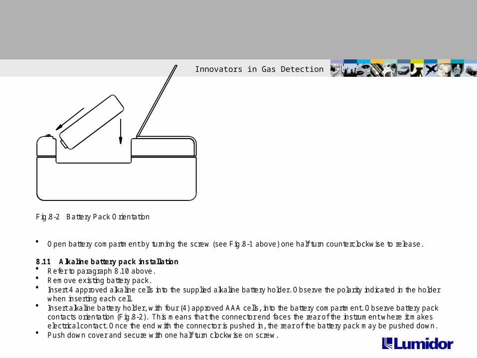
Fig.8-2 Battery Pack Orientation
Open battery compartment by turning the screw (see Fig.8-1 above) one half turn counterclockwise to release.
8.11 Alkaline battery pack installation Refer to paragraph 8.10 above. Remove existing battery pack. Insert 4 approved alkaline cells into the supplied alkaline battery holder. Observe the polarity indicated in the holder
when inserting each cell. Insert alkaline battery holder, with four (4) approved AAA cells, into the battery compartment. Observe battery pack
contacts orientation (Fig.8-2). This means that the connector end faces the rear of the instrument where it makeselectrical contact. Once the end with the connector is pushed in, the rear of the battery pack may be pushed down.
Push down cover and secure with one half turn clockwise on screw.

Innovators in Gas Detection
8.12NiMH battery pack installation Refer to paragraph 8.10 above. Remove existing battery pack. Insert the MPRO NiMH rechargeable battery pack into battery compartment as
shown. (Fig. 8-2 above). The connector end faces the rear of the instrumentwhere it makes electrical contact. Once the end with the connector is pushedin, the rear of the battery pack may now be pushed down.
Push down cover and secure with one half turn clockwise on screw. Charge instrument prior to use.
8.13 NiMH Battery Pack The supplied NiMH battery pack represents the latest in battery technology
and as an added benefit does not have the environmental problems associatedwith Nickel Cadmium technology.
It should be left on charge when not in use. There is a small current drain onthe pack

Innovators in Gas Detection
8.14 Sensor Replacement
Turn-off instrument and remove the four (4) screws (Fig.8-3) securing the tophalf of the case.
Disconnect battery pack connector by lifting it straight up. Remove the single screw securing the gas plate (Fig.8-3) Remove sensor by lifting it straight up. Toxic sensors include a small wafer-thin printed circuit board as part of the
sensor assembly. Make sure that this board is removed with the sensor. If installing a new toxic sensor, it is necessary to remove any shorting clip or
spring attached to the sensor pins. Align pins of new sensor with sockets and push down to secure sensor. Reconnect gas plate and secure with screw Reconnect battery connector Install case cover and secure with 4 case screws Allow sensors to stabilize for 15 minutes prior to turn-on Calibrate instrument

Innovators in Gas Detection
8.15 Sensor removal or additionCAUTION: If you are adding or removing a sensor, be aware of the following:
Adding a sensor. This involves increasing the number of sensors in the instrument. Forexample, adding a fourth sensor to a three gas unit. Remove the plug, located on thegas-plate above the new sensor, so that gas is allowed to reach the new sensor.
Removing a sensor. This involves reducing the number of sensors in an instrument. Inthis event it is necessary to insert a plug in the gas plate to prevent gas leakage wherethe vacated sensor no longer resides.
8.16 CleaningClean exterior of instrument with a clean damp cloth. Do not use solvents, soap,polishes etc on the monitor
8.17 Pump inlet filter replacement If the inlet filter is clogged, the flow rate of the pump is decreased and in severe cases
the instrument will go into low flow alarm or the pump can be heard to be strugglingunder the increased load caused by the restriction
To replace the filter, use tweezers to pull the filter out and install a new filter. The newfilter is held in place by friction.

Innovators in Gas Detection
8.18 Sampling hose maintenance
Check water trap (part no.GFV196), the spherical disc located near the middleof the sampling hose, periodically to make sure it is clean and unobstructed.Replace if necessary.
Check the porous dust cap (part no.20HFC), located at the very end of thesampling hose, periodically to make sure it is clean and unobstructed.Replace if necessary.
8.19 Storage
If instrument will be out of service for more than two (2) months: Charge NiMH battery pack. Remove NiMH or alkaline pack from instrument. Remove O2 sensor if more than two years old. Store instrument in a contaminate-free area. Store instrument at ambient temperature.

Innovators in Gas Detection
Battery packConnector
Gas Plate

Innovators in Gas Detection
APPENDIX A Specifications
A. MechanicalDimensions 4.75”L x 3”H x 1.8”DWeight < 17.6 ounces.
B. Operating Temperature Range-20 degrees C to + 50 degrees C(-4 degrees F to + 122 degrees F)
C. Operating Relative Humidity RangeContinuous 0-90% (Noncondensing)Intermittent 0-95% (Noncondensing)
D. Power SourcesRechargeable NiMH battery pack orFour AAA alkaline batteries
E. Battery LifeRechargeable NiMH pack 12 hoursFour AAA alkaline batteries 9 hours
F. Alarm outputsAudible >90db at 1 footVisual Large LED bar; Flashing display characters

Innovators in Gas Detection
G. Gas Ranges & Resolution
Sensor Instrument ResolutionRange
Combustible (LEL) 0-100% LEL 1%LELCombustible (% by vol.) 0-100% CH4 1%Oxygen (O2) 0-40% 0.1%Carbon Monoxide (CO) 0-999PPM 1PPMHydrogen Sulfide (H2S) 0-500PPM 1PPMSulfur Dioxide (SO2) 0-20PPM 0.1PPMPhosphine (PH3) 0-20PPM 0.1PPMAmmonia (NH3) 0-200PPM 1PPMChlorine (CL2) 0-20PPM 0.1PPMChlorine Dioxide (CLO2) 0-9.9PPM 0.1PPMCombo-Tox (CO/H2S) 0-500PPM 1PPMNitrogen Dioxide (NO2) 0-50PPM 0.1PPMHydrogen Cyanide (HCN) 0-50PPM 1PPM
WARNING: If instrument is used in oxygen environments below 10%, the displayed LEL reading will belower than actual value. In this event use of dilution tube, part no. MAX-DT, is recommended.
H. Repeatability+/- 2%
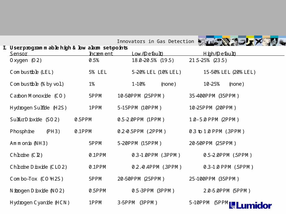
Innovators in Gas DetectionI. User programmable high & low alarm set-points
Sensor Increment Low/(Default) High/(Default)Oxygen (O2) 0.5% 18.0-20.5% (19.5) 21.5-25% (23.5)
Combustible (LEL) 5% LEL 5-20%LEL (10%LEL) 15-50%LEL (20%LEL)
Combustible (%by vol.) 1% 1-10% (none) 10-25% (none)
Carbon Monoxide (CO) 5PPM 10-50PPM (25PPM) 35-400PPM (35PPM)
Hydrogen Sulfide (H2S) 1PPM 5-15PPM (10PPM) 10-25PPM (20PPM)
Sulfur Dioxide (SO2) 0.5PPM 0.5-2.0PPM (1PPM) 1.0- 5.0 PPM (2PPM)
Phosphine (PH3) 0.1PPM 0.2-0.5PPM (.2PPM) 0.3 to 1.0 PPM (.3PPM)
Ammonia (NH3) 5PPM 5-20PPM (15PPM) 20-50PPM (25PPM)
Chlorine (Cl2) 0.1PPM 0.3-1.0PPM (.3PPM) 0.5-2.0PPM (.5PPM)
Chlorine Dioxide (CLO2) 0.1PPM 0.2.-0.4PPM (.3PPM) 0.3-1.0 PPM (.5PPM)
Combo-Tox (CO\H2S) 5PPM 20-50PPM (25PPM) 25-100PPM (35PPM)
Nitrogen Dioxide (NO2) 0.5PPM 0.5-3PPM (3PPM) 2.0-5.0PPM (5PPM)
Hydrogen Cyanide (HCN) 1PPM 3-5PPM (3PPM) 5-10PPM (5PPM

Innovators in Gas Detection
J. Time Weighted Averages (Toxic sensors only)
Gas\Sensor Default Set-pointsInstantaneous STEL TWA
PPM PPM PPMCarbon Monoxide (CO) 200 100 35Hydrogen Sulfide (H2S) 20 15 10Sulfur Dioxide (SO2) 10 5 2Hydrogen Cyanide (HCN) 10 5 5Phosphine (PH3) 10 1 0.3Ammonia (NH3) 50 35 25Chlorine (CL2) 5 1 0.5Chlorine Dioxide (CLO2) 0.3 0.3 0.3Combo/Tox (CO/H2S) 200 100 35Nitrogen Dioxide (NO2) 5 3 1
Innovators in Gas Detection
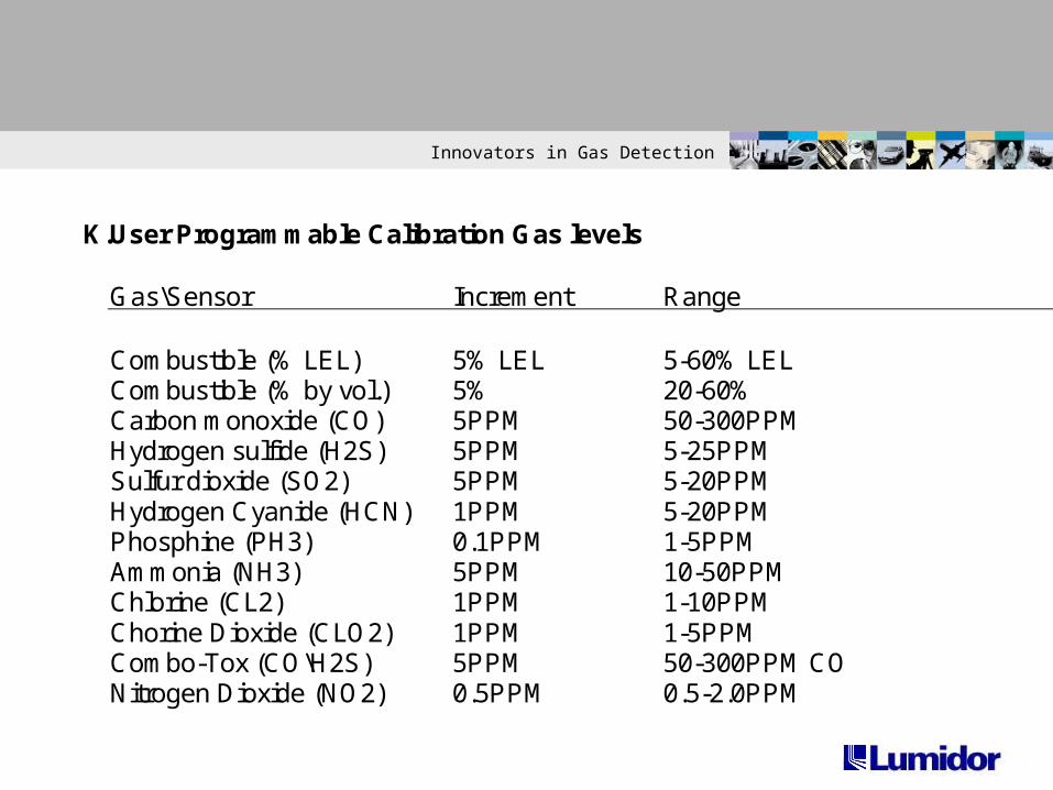
K. User Programmable Calibration Gas levels
Gas\Sensor Increment Range
Combustible (% LEL) 5% LEL 5-60% LELCombustible (% by vol.) 5% 20-60%Carbon monoxide (CO) 5PPM 50-300PPMHydrogen sulfide (H2S) 5PPM 5-25PPMSulfur dioxide (SO2) 5PPM 5-20PPMHydrogen Cyanide (HCN) 1PPM 5-20PPMPhosphine (PH3) 0.1PPM 1-5PPMAmmonia (NH3) 5PPM 10-50PPMChlorine (CL2) 1PPM 1-10PPMChorine Dioxide (CLO2) 1PPM 1-5PPMCombo-Tox (CO\H2S) 5PPM 50-300PPM CONitrogen Dioxide (NO2) 0.5PPM 0.5-2.0PPM
Innovators in Gas Detection
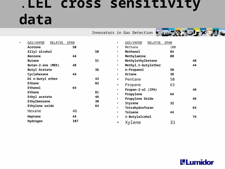
.LEL cross sensitivity data
• GAS/VAPOR RELATVE SPAN
Acetone 50
Allyl alcohol 50
Benzene 44
Butane 51
Butan-2-one (MEK) 48
Butyl Acetate 36
Cyclohexane 44
Di n-butyl ether 43
Ethane 82
Ethanol 64
Ethene 81
Ethyl acetate 46
Ethylbenzene 30
Ethylene oxide 64
Hexane 46
Heptane 44
Hydrogen 107
• GAS/VAPOR RELATVE SPAN• Methane 100 • Methanol 84• Methylamine 80• Methylethylketone 48• Methyl,t-butylether 44• n-Propanol 50• Octane 38
• Pentane 50• Propane 63• Propan-2-ol (IPA) 49• Propylene 64• Propylene Oxide 46• Styrene 32• Tetrahydrofuran 64• Toluene 44• t-Butylalcohol 74
• Xylene 31

Innovators in Gas Detection
N. User Programmable calibration gas levels
Sensor Increment Range
Combustible (LEL) 5% LEL 5 –60 % LELCombustible (% by vol.) 5% 20 – 60 %Carbon Monoxide (CO) 5 ppm 50 – 300 ppmHydrogen Sulfide (H2S) 5 ppm 5 – 25 ppm Sulfur dioxide (SO2) 5 ppm 5 – 20 ppmHydrogen Cyanide (HCN) 1 ppm 5 – 20 ppmPhosphine (PH3) 0.1 ppm 1 - 5 ppmAmmonia (NH3) 5 ppm 10 – 50 ppmChlorine (CL2) 1 ppm 1 – 10 ppmChlorine Dioxide (CLO2) 1 ppm 1 - 5 ppmCombo-Tox (CO/H2S) 5 ppm 50- 300 ppm (CO)Nitrogen Dioxide (NO2) 0.5 ppm 0.5 – 2 ppm

Innovators in Gas Detection
This instrument is warranted, to the original end-user purchaser, against defects in materials andworkmanship for the life of the product, excluding the battery and pump, which carry a two year limitedwarranty. During this period Lumidor Safety Products will repair or replace defective parts on anexchange basis, F.O.B. the factory at Miramar, Florida. The end-user purchaser will pay freightcharges to and from Lumidor. The decision to repair or replace parts shall be determined by LumidorSafety Products.
Sensor Warranties1. The oxygen sensor is guaranteed to operate satisfactorily for two years from the date of sale (i.e.the date of shipment) and will be replaced at no charge within that period only if it will not provide acorrect reading after calibration by authorized service personnel. Physical or chemical damage,resulting from exposure to improper elements, is not covered.
2. The combustible sensor is guaranteed to operate satisfactorily for two years from date of sale(i.e.from date of shipment). If It will not provide a correct reading after calibration by authorized servicepersonnel It will be replaced at no charge within that period . This guarantee is void if it has beencontaminated by some unusual substance, including but not limited to, water and/or other liquids, oilycompounds, corrosives, silicones, lead vapors, extremely high concentrations of combustible gases,and various particulates which may inhibit gas flow to the sensor element.
3. The toxic sensors are guaranteed to operate satisfactorily for two years (18 months for CL2, CLO2and HCN sensors, 12 months for the NH3 sensor) from date of sale (i.e. the date of shipment). Theywill be replaced at no charge within that period only if they will not provide a correct reading aftercalibration by authorized service personnel, and only if the sensor membranes exhibit no physical orchemical damage resulting from exposure to improper substances.
Lifetime Warranty

Innovators in Gas Detection
Conditions and exclusionsTo maintain this warranty, purchaser must perform maintenance and calibration as prescribed in theinstrument operation manual, including prompt replacement or repair of defective parts and such othernecessary calibration, maintenance and repair as may be required, according to the use of theinstrument, in the reasonable judgment of Lumidor Safety Products. Normal wear and tear, and partsdamaged by abuse, misuse, negligence or accidents are specifically excluded from the warranty.Purchaser acknowledges that, notwithstanding any contrary term or provision in the purchaser’spurchase order or otherwise, the only warranty extended by Lumidor Safety Products is the expresswarranty contained herein. Purchaser further acknowledges that there are no other warrantiesexpressed or implied, including without limitation, the warranty of merchantability or fitness for aparticular purpose; that there are no warranties which extend beyond the description of the facehereof; that no oral warranties, representations, or guarantees of any kind have been made by LumidorSafety Products, it’s distributors or the agents of either of them, that in any way alter the terms of thiswarranty; that Lumidor Safety Products and its distributors shall in no event be liable for anyconsequential or incidental damages, including but not limited to injury to the person or property of thepurchaser or others, and from other losses or expenses incurred by the purchaser arising from the use,operation, storage or maintenance of the product covered by the warranty; that Lumidor SafetyProducts liability under this warranty is restricted to repair or replacement of defective parts at LumidorSafety Products sole option; and that Lumidor Safety Products neither assumes nor authorizes anyother person to assume for it any other warranty. The warranty shall be void if serial numbers affixedto the products are removed, obliterated or defaced.
Lumidor Safety Products, Miramar, Florida.