
You are always a winner with Bhansali quality. BBhansali (RG Series), KATHERIN, etc. 2 Copper...
30
B Bhansali Cables & Conductors Private Limited You are always a winner with Bhansali quality.
Transcript of You are always a winner with Bhansali quality. BBhansali (RG Series), KATHERIN, etc. 2 Copper...

B BhansaliCables & ConductorsPrivate Limited
You are always a winner with Bhansali quality.

The Bhansali Range of CablesApplications
■ Radio transmission systems■ CATV, MATV and CCTV systems■ Electrical instruments■ LAN, WAN, ETHERNET, ARCNET, NOVELL, and other
complex applications■ Dual coax-workstation for large word processing systems
■ Telephone Systems of any project■ EPABX systems■ In-house telephone wiring, etc.
■ Thermal power projects■ Fire alarm systems■ Refineries and petrochemical projects■ Chemical plants■ Fire hazard areas■ Transmission systems, etc■ Computer controlled electrical and electronic equipment■ Lifts and conveyor belts
■ Data Acquisition Systems (DAS)■ RTD from junction boxes■ To connect various instruments to main junction box■ Computer networks■ Digital control monitoring and information systems■ To connect local junction boxes to terminal boxes■ Electrical and electronic equipment.
■ Electric instruments and public address systems■ Piped music■ Interconnection of electrical machines, instruments and
control panels, etc.
■ Interconnection of electrical machines, instruments andcontrol panels, etc.
■ All types of thermocouples as per IS, BS, ANSI, DIN andJIS standards.
■ Electronic and computer applications■ Spacecraft wiring■ Under carpet wiring■ High flexibility applications
■ High frequency IF coils/deflection components for Audio/TV/Telecommunications and professional electronics
■ Electronic push button telephones/EPABX, computersystems, etc.
Cable Type
1 Radio Frequency Coaxial Cables as per British Standards2316 (UR Series), American Military Standards MIL-C17D (RG Series), KATHERIN, etc.
2 Copper Conductor PVC Insulated Multipair TelephoneCables with option of Screened/Unscreened pairs, Jelly-filled Armoured/Unarmoured, conforming to specificationsof ITD, OKL, IEB, BPO, etc.
3 Instrumentation/Control & Data Cables with HR PVC andFlame Retardant Low Smoke Outer Sheath as perNational/International specifications.
4 Flexible/Solid Copper Conductor PVC/PolyethyleneInsulated Aluminium/Copper Tape Screen Pair/Triads/
Unit Formation with Individual/Overall Screened.Armoured/Unarmoured PVC Sheathed suitable up to
1.1 kV as per customer specifications.
5 Copper Conductor PVC/Polyethylene Insulated CopperWire Braided Screened Instrumentation Cables.
6 Copper Conductor PVC Insulated Armoured/UnarmouredControl Cables suitable for 1.1 kV as per IS:1554(PART-I) & BS:5308
7 Compensating Cables & Thermocouple Extension Cables
8 Flat Ribbon Cables PVC Insulated Bonded/Extruded
9 Other Winding Wires, Litz Wires, etc.
10 Telephone Coil Cords and Straight Cords, etc., ComputerCables and Assemblies.
Note: We also specialise in the manufacture of custom made cables as per customer’s specific requirements.
Index
External Telecom Cables
External Telecom Cables
1128
1179
1198
1252
1236
Dropwire No 1
Internal Telecom Cables
1293
1308
1308 Screened
1600
1311
1316
1044
1109
Cables For Transmission Equipment
Twin coaxial Cable
120Ω PCM Cables
RF Coaxial Cables for Various Antenna
Elaky Cables
Screened Telecom PTS
Equipment Wire
Internal Wiring of Telecables
Energy Cables
Batteries in Telecom Power Plants
LAN Cables
Cat 5e
Cat 6
Instrumentation Cables
BS:5308 Part 1/2
Cables to BS:6500
Cables to BS:6004
CATV Coaxial Cables
RG-6 (Foam)
RG-6 (Airspace)
RG-11
Lift Cable

Radio Frequency Coaxial CablesBhansali manufactures one of the most comprehensivelines of coaxial cables available from any single source.Signal transmission in electronic applications and datacommunications is changing in a dramatic way. Cables nowhave to accommodate faster signal speeds over longerdistance with less signal loss. Additionally, new shieldingrequirements to meet FCC RFI/EMI emission controls,tougher fire/temperature requirements requiring specialmaterials in critical installations and demands for highdensity wiring are factors which have been considered inmany of our coaxial and data cable products. Our productsare designed to meet these needs for safe and reliabletransmission of voice, video and data.
Bhansali coaxial cable products are supplied in 50, 75, 93,125 and 150 ohms impedance grades for most voice, videoand data applications. Our comprehensive line includes:■ Standard RG/URM/JSS/JIS type coax for commercial
and defence use■ Triaxial cables-balanced lines for reduced crosstalk■ Triaxial cables■ MATV and CATV Cables■ Networking load for LAN, WAN, ETHERNET, ARCNET,
NOVELL LAN D-LINK and other complex applications■ Dual Coax-workstation for large word processing
systems.
Item Conductor Dia over O.D. Impedance Attenuation Max R.F.(Replaces) Size Dielectric at 200 MHz operating
voltage
NORMAL VALUES
(mm) (mm) (mm) (ohms) (dB/100 m) kV
Characteristic impedance 50-55 ohms
RG-174/U 7/0.16 (C) 1.50 2.5 50 40 1.5 rms
RG-122/U 27/0.127 (T) 2.40 4.1 50 36 1.9 rms
RG-58/U 0.81 (P) 2.95 5.0 53.5 23 1.9 rms
RG-58C/U 19/0.18 (T) 2.95 5.0 50 24 1.9 rms
URM-43 (UR 43) 0.9 (P) 2.95 5.0 50 19 2.6 peak
URM-76 (UR 76) 7/0.32 (P) 2.95 5.0 50 22 2.6 peak
RG-55B/U 0.81 (S) 2.95 5.2 53.5 20 1.9 rms
RG-223/U (RG-55A/U) 0.9 (S) 2.95 5.5 50 20 1.9 rms
URM-115 0.9 (P) 2.95 7.2 50 19 2.0 peak
RG-212/U (RG-5B/U) 1.2 (S) 4.70 8.4 50 14 3.0 rms
RG-213/U (RG-8A/U) Similar to and substitutes URM-67 and UR-67
7/0.75 (P) 7.25 10.3 50 11 5.0 rms
RG-214/U (RG-9B/U) Similar to and substitutes URM-112 and UR-112
7/0.75 (S) 7.25 10.8 50 11 5.0 rms
URM-91 (UR-91) 7/0.76 (P) 7.25 11.0 50 10 6.5 peak
RG-217/U (RG-14A/U) 2.7 (P) 9.8 13.8 50 7 7.0 rms
RG-218/U (RG-17A/U) Similar to and substitutes URM-74 and UR-74
4.95 (P) 17.3 22.1 50 4 11.0 rms

Item Conductor Dia over O.D. Impedance Attenuation Max R.F.(Replace) Size Dielectric at 200 MHz operating
voltage
NORMAL VALUES
(mm) (mm) (mm) (ohms) (dB/100 m) kV
Characteristic impedance 70-75 ohms
URM-200 7/0.2 (P) 2.45 4.1 75 23 Foam-PE
dielectricURM-201 0.71 (P) 3.25 5.1 75 16 -do-URM-202 7/0.25 (P) 3.25 5.1 75 16 -do-
URM-210 7/0.19 (P) 3.25 5.8 75 22 -do-URM-70 (UR-70) 7/0.19 (P) 3.25 5.8 75 22 1.8 peakUR-56 0.56 (P) 3.25 5.9 71 18 2.5 peak
URM-117 7/0.212 (P) 3.70 6.0 75 18 2.6 peakRG-59B/U 0.58 (C) 3.70 6.1 75 16 2.3 rmsRG-59/U 0.63 (P) 3.70 6.2 73 16 2.3 rms
URM-203 1.12 (P) 5.10 7.3 75 11 Foam-PEdielectric
URM-204 1.25 (P) 5.60 7.8 75 10 -do-
UR-54 7/0.193 (P) 3.25 8.3 72 22 1.8 peakURM-206 1.4 (P) 6.35 8.7 75 8 Foam-PE
dielectric
RG-11A/U 7/0.41 (P) 7.25 10.3 75 11 5.0 rmsUR-59 1.12 (P) 7.25 10.3 75 9 5.0 peakURM-65 (UR-65) 1.15 (P) 7.25 10.3 75 9 5.0 rms
RG-216/U (RG-13A/U) 7/0.41 (T) 7.25 10.8 75 15 5.0 rmsUR-21 1.42 (P) 8.40 11.5 71 8 5.0 peakUR-60 1.12 (P) 7.25 11.7 75 9 5.0 peak
RG-34B/U 7/0.64 (P) 11.70 16.0 75 7 6.5 rmsURM-77 (UR-77) 2.65 (P) 17.30 22.0 75 5 12.5 peakSimilar to and substitutes RG-164/U
RG-62A/U 0.64 (C) 3.7 6.1 93 12 0.75 rmsSemi-air spacedRG-71B/U 0.64 (P) 3.7 6.4 93 12 0.75 rms
Semi-air spacedRG-63 B/U 0.64 (P) 7.25 10.3 125 9 1.00 rmsSemi-air spaced
RG-22/U 2x7/0.38 (P) 7.25 10.3 95 20 1.00 rmsUR-78 0.61 (P) 7.25 10.3 100 11 3.7 rmsRG-57A/U 2x7/0.12 12.0 15.9 95 12 3.0 rms
Twin conductor
Note: If you have a new or unusual application or if you cannot find a cable in this section which meets your requirement, then,please contact us. We can design a custom-made cable for you.
P=Plain copper, T=Tinned copper, S=Silver plated, C=Copper coated steel. Colour: Sheathing — grey/black/white.Packing: As per customer requirements.

Equipment WiresOur commitment to quality and service starts from the
beginning...with the manufacturing of a Single Conductor
Hook up wire, the most basic wiring component.
Our hook up wires, lead wires and equipment wires are
manufactured in a variety of material, size and designs to
meet rigid industrial and goverment specifications.
Used extensively for both electrical and electronic
equipment where applications range from inter-connection
circuits to internal wiring of computers and data processing
equipment, etc.
Size (mm) Nominal area Insulation thickness Max. overall Max. cont. Voltage rating(mm²) (mm) Diameter (mm) Current Rat. (amp) DC AC
7/.10 0.054 0.15 0.70 0.34 750 500
7/.12 0.080 0.15 0.75 0.51 750 500
7/.15 0.16 0.35 1.1/1.30 1.05 1500 1000
7/.193 0.20 0.30 1.30 1.28 1500 1000
7/.2 0.22 0.30 1.30 1.36 1500 1000
14/.15 0.33 0.40 1.65 2.10 1500 1000
14/.193 0.41 0.40 1.75 2.62 1500 1000
14/.2 0.44 0.40 1.80 2.81 1500 1000
16/.2 0.50 0.40 1.80 3.11 1500 1000
19/.10 0.15 0.25 1.10 1.00 750 500
24/.2 0.75 0.40 2.20 4.66 1500 1000
32/.2 1.00 0.40 2.30 6.20 1500 1000
48/.2 1.50 0.50 2.80 9.33 1500 1000
63/.2 2.00 0.50 3.00 12.44 1500 1000
80/.2 2.50 0.60 3.50 15.55 1500 1000
128/.2 4.00 0.60 4.00 24.88 1500 1000
23/38 0.42 0.40 1.70 2.61 1500 1000
23/36 0.68 0.40 2.10 4.23 1500 1000
40/36 1.17 0.45 2.80 7.26 1500 1000
70/36 2.00 0.50 3.45 12.44 1500 1000
110/36 3.20 0.60 4.00 19.84 1500 1000
Technical Data
Conductor: Bare copper/tinned, copper/pre-twisted
and tinned copper complying with
BS:6360
Insulation: PVC compound complying with
BS:6746
Operating Heat resistant -20° C to + 85°/+105° C
temperature: Low temperature -40° C to +70° C
Normal wires -15° C to + 70° C

The growing sophistication of the electronic industrycontinues to create a need for specially designed cablesfor use with computer-controlled electrical and electronicequipment. To satisfy requirements for impedancematching, lower bit error rates, lower crosstalk, longertransmission distances and high signal purity, we aremanufacturing an expanding spectrum of instrumentation,data and control cables in full range of sizes, insulations ofdifferent types, shields types for special installations. Wecan also armour these cables for mechanical protection.
Conductor Solid/stranded, tinned/bare/silver plated andmade up of annealed high conductivity EC Grade copperas per IEC-60228 with conductor sizes ranging from 0.5 sqmm to 10 sq mm.
Instrumentation and Data Cables (Multipair)Insulation PE/Foam PE/PP/PVC/Silicone/Special Thermo-plastic materials.Construction Paired/Triads or Quad construction withindividual/collective shields.Colour Scheme As per IEC/ITD/BS/As per customerspecifications.Shield Aluminium Mylar with ATC earth wire/Copper BraidShielding.Sheath PVC-FRLS/HR/Halogen Free/ST Grade, PU/Silicone or any other thermoplastic materials.Specifications BS 5308/IS Part 1 / Part 2 / Type 1 /Type 2
Unarmoured ArmouredConductor No of Nominal Overall Nominal Overall
Pairs diameter (mm) diameter (mm)
Part 1 / Type 2 • Collectively Screened1/0.8 mm (0.5 mm²) 1 6.3 10.7
2 (Quad) 7.1 11.55 11.6 16.2
10 15.0 20.720 19.4 26.030 23.0 29.8
16/0.2 mm (0.5 mm²) 1 7.0 11.42 (Quad) 7.9 12.3
5 13.1 17.910 17.2 22.920 22.3 29.130 26.9 33.9
24/0.2 mm (0.75 mm²) 1 7.3 11.72 (Quad) 8.3 12.9
5 14.3 19.810 18.7 25.320 24.5 31.330 29.5 37.5
1/1.13 mm (1.0 mm²) 1 7.4 11.82 (Quad) 8.4 13.0
5 14.2 19.710 18.4 24.320 24.4 31.230 29.0 36.2
7/0.53 mm (1.5 mm²) 1 8.3 12.92 (Quad) 9.7 14.3
5 16.4 22.110 21.6 28.420 28.5 35.730 34.3 42.5

Instrumentation and Data Cables (Multipair)Unarmoured Armoured
Conductor No of Nominal Overall Nominal OverallPairs diameter (mm) diameter (mm)
Part 1 / Type 2 • Individual Pair and Collectively Screened1/0.8 mm (0.5 mm²) 2 10.3 14.9
5 13.5 19.010 18.3 24.220 23.5 30.330 27.9 34.9
16/0.2 mm (0.5 mm²) 2 12.0 16.85 15.2 20.9
10 21.1 27.920 27.3 34.330 32.3 40.5
24/0.2 mm (0.75 mm²) 2 12.8 17.65 16.3 22.0
10 22.7 29.520 29.8 37.830 35.5 --
1/1.13 mm (1.0 mm²) 2 12.8 17.65 16.2 21.9
10 22.6 29.420 29.8 37.830 35.4 --
7/0.53 mm (1.5 mm²) 2 14.7 20.45 18.8 25.4
10 26.5 33.520 34.4 42.630 41.0 --
Part 2 / Type 2 • Collectively Screened16/0.2 mm (0.5 mm²) 1 7.0 11.4
2 (Quad) 7.9 12.35 13.1 17.9
10 17.2 22.920 22.3 29.130 26.9 33.9
24/0.2 mm (0.75 mm²) 1 7.3 11.72 (Quad) 8.3 12.9
5 14.3 19.810 18.7 25.320 24.5 31.330 29.5 37.5
7/0.53 mm (1.5 mm²) 1 8.3 12.92 (Quad) 9.7 14.3
5 16.4 22.110 21.6 28.420 28.5 35.730 34.3 --

Bhansali can supply a wide range of control cables, i.e., copper/aluminium conductor. The control
cables generally have the ability to transmit electricity and signals so that you can avoid
transformation of signals from low voltage in order to control motors and relays. Electromagnetic
disturbances generally have no influence due to the strength of the signals, or we can say that
Control Cables play a vital and keen role in our systems.The high flexibility in control cables is achieved by the use of fine wire copper strands, short lay
lengths and by powdering of the cores to decrease and maintain core separation.
We are renowned for our control cables which generally have the following characteristics:
● Stranded/Solid conductor
● Multi-core cables (available up to 61 cores)
● Primary insulation (Type A, Type C, HR- 85°C/105°C)
● Voltage grade 1100 Volts
● Core identification as per ISI colour code along with numbering
● Sheath materials PVC ST-1, ST-2, HR, FRLS, Halogen Free
● Armoured/unarmoured (round wire/flat strip)
● Jacket materials PVC ST-1, ST-2, HR, FRLS, Halogen Free
Description
Solid/stranded annealed plain high conductivity electrolytic grade copper/aluminium conductor
confirming to IS:5831 (1984).
Individual core insulated with extruded PVC compound type ‘A’ confirming to IS: 5831 (1984).
All such cores laid up in a common covering of PVC called inner sheath, Armoured with galvanised
mild steel wire/strip confirming to IS:3975 (1979) and finally jacketed with extruded PVC type ST-1
confirming to IS:5831(1984).
Technical Data
For Copper, Control Cables, Type YY / YWY / YFY
Conductor Stranding: Solid/Stranded (7 Strands)
Bending Radius (Min.) (For Single Core): 12 x Cable Diameter
Bending Radius (Min.) (For Multi Core): 15 x Cable Diameter
Colour Code: As per ISI
Working Voltage: 650/1100 Volts
Test Voltage: 3000 Volts
Insulation Resistance: 36.7 M Ohm/km
Note: The cables specified above conform to BIS standards. We also design, develop and manufacturecables as per various other international standards like VDE, BS, IEC, ASTM, JIS, etc., and also as perspecific customer requirements.
Control Cables (IS 1554 Part-I, 1988)

Cables to BS 6004We offer a wide range of copper electrical power cables forall domestic, commercial and industrial uses. All cablescomply with the relevant British Standards. We can supplyall standard PVC/XLPE/PVC underground cables andhousewiring cables.Technical DataSingle Core Conduit Cables: Solid or stranded plaincopper conductor, PVC insulated
Nominal Cross- Min. no of Radial thickness Mean Overall Approx. Nett HarmonisedSectional Area wires of insulation Diameter Weight per Code(mm²) (mm) Upper Limit (mm) 1 km1.0 1 0.6 2.8 15 H05V-U1.5 1 0.7 3.3 21 H07V-U1.5 6 0.7 3.5 21 -2.5 1 0.8 3.9 33 H07V-U2.5 6 0.8 4.2 35 -
4.0 6 0.8 4.8 50 -6.0 6 0.8 5.4 70 H07V-R10.0 6 1.0 6.8 120 H07V-R16.0 6 1.0 8.0 175 H07V-R25.0 6 1.2 9.8 290 H07V-R35.0 6 1.2 11.0 400 H07V-R
50.0 15 1.4 13.0 565 H07V-R70.0 15 1.4 15.0 770 H07V-R95.0 15 1.6 17.0 1010 H07V-R120.0 30 1.6 19.0 1260 H07V-R150.0 30 1.8 21.0 1580 H07V-R185.0 30 2.0 23.5 1900 H07V-R
240.0 51 2.2 26.5 2500 H07V-R
Single Core Double Insulated Cables/Twin and EarthedCables/Three Core and Earthed Cables: Solid orstranded, plain copper conductor.Normal Duty Flexible Cords: Flat twin, Circular twin,Circular 3 core, Circular 4 core.Light Flexible Cord: Flat twin, Circular twin, Circular 3core, Circular 4 core, plain copper flexible conductor, PVCinsulated, PVC sheathed.
Single Core Conduit Cables
Nominal Cross- Min. no of Radial thickness Mean Overall Diameter Approx. NettSectional Area wires Weight per(mm²) Insulation (mm) Sheath (mm) Lower Limit Upper Limit 1 km
1.0 1 0.6 0.8 3.8 4.5 261.5 1 0.7 0.8 4.2 4.9 352.5 1 0.8 0.8 4.8 5.8 554.0 6 0.8 0.9 5.4 6.8 756.0 6 0.8 0.9 6.0 7.4 9510.0 6 1.0 0.9 7.2 8.8 15516.0 6 1.0 1.0 8.4 10.5 22525.0 6 1.2 1.1 10.0 12.5 34035.0 6 1.2 1.1 11.0 13.5 445
Single Core Double Insulated Cables

Nominal Cross- Min. no of Radial thickness Mean Overall Diameter Earth Approx. NettSectional Area wires Continuity Weight per
Conductor 1 kmCross Section
(mm²) Insulation (mm) Sheath (mm) Lower Limit Upper Limit1.0 1 0.6 0.9 4.0x7.2 4.7x8.6 1.0 681.5 1 0.7 0.9 4.4x8.2 5.4x9.6 1.0 852.5 1 0.8 1.0 5.2x9.8 6.2x11.5 1.5 1204.0 6 0.8 1.0 5.6x10.5 7.2x13.0 1.5 1756.0 6 0.8 1.1 6.4x12.5 8.0x15.0 2.5 24010.0 6 1.0 1.2 7.8x15.5 9.6x19.0 4.0 39016.0 6 1.0 1.3 9.0x18.0 11.0x22.0 6.0 560
Single Core Double Insulated Cables
Nominal Cross- Min. no of Radial thickness Mean Overall Diameter Earth Approx. NettSectional Area wires Continuity Weight per
Conductor 1 kmCross Section
(mm²) Insulation (mm) Sheath (mm) Lower Limit Upper Limit1.0 1 0.6 0.9 4.0x9.6 4.7x11.0 1.0 911.5 1 0.7 0.9 4.4x10.5 5.4x12.5 1.0 1152.5 1 0.8 1.0 5.2x12.5 6.2x14.5 1.5 1704.0 6 0.8 1.1 5.8x14.5 7.4x18.0 1.5 2506.0 6 0.8 1.1 6.4x16.5 8.0x20.0 2.5 34010.0 6 1.0 1.2 7.8x21.0 9.6x25.5 4.0 54016.0 6 1.0 1.3 9.0x24.5 11.0x29.5 6.0 790
Three Core and Earthed Cables

Nominal Cross- Max Dia. Radial thickness Mean Overall Diameter HarmonisationSectional Area of wires Code(mm²) Insulation (mm) Sheath (mm) Lower Limit Upper Limit
0.75 0.21 0.6 0.8 3.8x6.0 5.2x7.6 H05VVH2-F
0.5 0.21 0.6 0.8 5.6 7.0 --0.75 0.21 0.6 0.8 6.0 7.6 H05VV-F1.0 0.21 0.6 0.8 6.4 8.0 H05VV-F1.25 0.21 0.7 0.8 7.0 8.6 --1.5 0.26 0.7 0.8 7.4 9.0 H05VV-F2.5 0.26 0.8 1.0 8.9 11.0 H05VV-F
0.75 0.21 0.6 0.8 6.4 8.0 H05VV-F1.0 0.21 0.6 0.8 6.8 8.4 H05VV-F1.25 0.21 0.7 0.9 7.6 9.4 --1.5 0.26 0.7 0.9 8.0 9.8 H05VV-F2.5 0.26 0.8 1.1 9.6 12.0 H05VV-F
0.75 0.21 0.6 0.8 6.8 8.6 H05VV-F1.0 0.21 0.6 0.9 7.6 9.4 H05VV-F1.5 0.26 0.7 1.0 9.0 11.0 H05VV-F2.5 0.26 0.8 1.1 10.5 13.0 H05VV-F
Normal Duty Flexible Cords
Nominal Cross- Max Dia. of Radial thickness Mean Overall Diameter Approx. Nett Harmon-Sectional Area wires Weight per isation
1 km Code
(mm²) Insulation (mm) Sheath (mm) Lower Limit Upper Limit0.5 0.21 0.5 0.6 3.0x4.8 3.6x6.0 29 --0.75 0.21 0.5 0.6 3.2x5.2 3.9x6.4 36 H03VVH2-F
0.5 0.21 0.5 0.6 4.8 6.0 39 H03VV-F0.75 0.21 0.5 0.6 5.2 6.4 48 H03VV-F
0.5 0.21 0.5 0.6 5.0 6.2 46 H03VV-F0.75 0.21 0.5 0.6 5.4 6.8 56 H03VV-F
Light Flexible Cord

Local Area Network Cables
RG type Inner Dia over Dia over Impedanceconductor dielectric (mm) jacket (mm)
RG-11 U 7/0.41 mm 7.25 10.3 75 ohms
ATC
RG-6 U 18 AWG 7.0 9.5 75 ohms
RG-59 U 0.63 mm 3.7 6.2 75 ohmsABC
RG-62 U 0.64 mm 3.71 6.15 93 ohms
Apple Talk 22 AWG 1.65 4.7 78 ohms
Thick Ethernet 2.15 mm 6.5 mm 11.0 mm 50 ohms(as per IEEE 802.3) ABC ±0.15 mm ±0.5 mm
RG-58 C/U 19/0.18 mm 2.95 5.0 50 ohmsATC
Local area network systems (LANs) have emerged as a
key development as society progresses into the
“Information Age”. LANs integrate computer and
communication technologies to meet the demand for
efficient information for data processing, handling,
collection and distribution. LANs fulfill their function
throughout a local region without using public, telephone,
microwave or satellite links.
Regardless of LAN topology, cabling is the key element
which provides for distribution and communication
throughout the network. Coaxial cables of 50 ohms, 75
ohms, 93 ohms and 125 ohms and twisted pair with special
impedance characteristics are utilized. They may be used
to fulfill the trunk cable distribution and drop cable
distribution and drop cable node/work station attachment.
The choice of 50 ohms, 75 ohms, 93 ohms and 125 ohms
coaxial cable or twisted pair is made after careful study of
system data speed and electrical requirements. Electrical
characteristics of concern are characteristic impedance,
attenuation, velocity of propagation, and shield effect.
The cable you choose to tie together your LAN is the life
line of your system. At Bhansali we help you achieve
optimum system performance by providing you with LAN
cables best suited to your specific applications.
As a leading technological innovator we are ready to help
you to meet the challenge of the future.
TRANSRECEIVER/DROP CABLES
Tinned copper, PE/PP/Foam PE/Special Insulating
materials, twisted pair, each pair individually aluminium foil
shielded with drain wire. Then overall Al. foil shielded and
then again tinned copper braid shielded and PVC
sheathed. All these cables are tailor-made as per customer
spec. of impedance, conductor size, etc.
TELEPHONE CABLES FOR LAN
Tinned copper 20 to 28 AWG PVC/PE/Foam PE insulated,
twisted pair, laid-up Malinex taped, shielded/ unshielded
and then PVC sheathed cables as per customer specs.
Trunk Coaxial Cables

CAT-5e Cables (Screened / Unscreened)Our CAT 5 Enhanced cables are designed to exceed
category 5e specifications in PVC/FRLS/LSOH jacket
options. They comply with all of the performance
requirements for current and proposed applications such
as Gigabit Ethernet, 100 BASE-Tx, token ring, 155 Mbps
ATM, 622Mbps ATM, 100 Mbps TP-PMD, ISDN, analog
(broadband, baseband) and digital video & voice.
Technical Data
Conductor Type: 24 AWG Solid/Stranded Plain
Annealed Copper
Insulation: Colour-coded PE Insulation
Colour Codes: 1P-White-Blue/Blue, 2P-White-
Orange/Orange, 3P-White-Green/
Green, 4P-White-Brown/Brown
Common Shield: Aluminium/mylar tape with earth wire
Sheath: PVC/FRLS/LSOH
Flammability: IEC-332
Freq. Attenuation Next PSNEXT ELFEXT PSELFEXT Return Loss ACR PS ACRMHz (dB/100 m) Max. (dB) Min. (dB) Min. (dB) Min. (dB) Min. (dB) Min. (dB) Min. (dB) Min.
.772 1.8 67 64 66 63 -/- 65.2 62.2
1 2.0 65.3 62.3 63.8 60.8 20.0 63.3 60.3
4 4.1 56.3 53.3 51.7 48.7 23.0 52.2 49.2
8 5.8 51.8 48.8 45.7 42.7 24.5 46.0 43.0
10 6.5 50.3 47.3 43.8 40.8 25.0 43.8 40.8
16 8.2 47.3 44.3 39.7 36.7 25.0 39.1 36.1
W20 9.3 45.8 42.8 37.7 34.7 25.0 36.5 33.5
25 10.4 44.3 41.3 35.8 32.8 24.3 33.9 30.9
31.25 11.7 42.9 39.9 33.9 30.9 23.6 31.2 28.2
62.5 17.0 38.4 35.4 27.8 24.8 21.5 21.4 18.4
100 22.0 35.3 32.3 23.8 20.8 20.1 13.3 10.3
Electrical Characteristics
DC Resistance (max.): 9.38Ω/100 metres.
DC Resistance Unbalance: 2% max.
Characteristic Impedance: 100 ±15Ω @ 1-100 MHz
Mutual Capacitance: 5.6 nF/100 metres.
Propagation Delay: 538 ns/100 metres max. @ 100 MHz
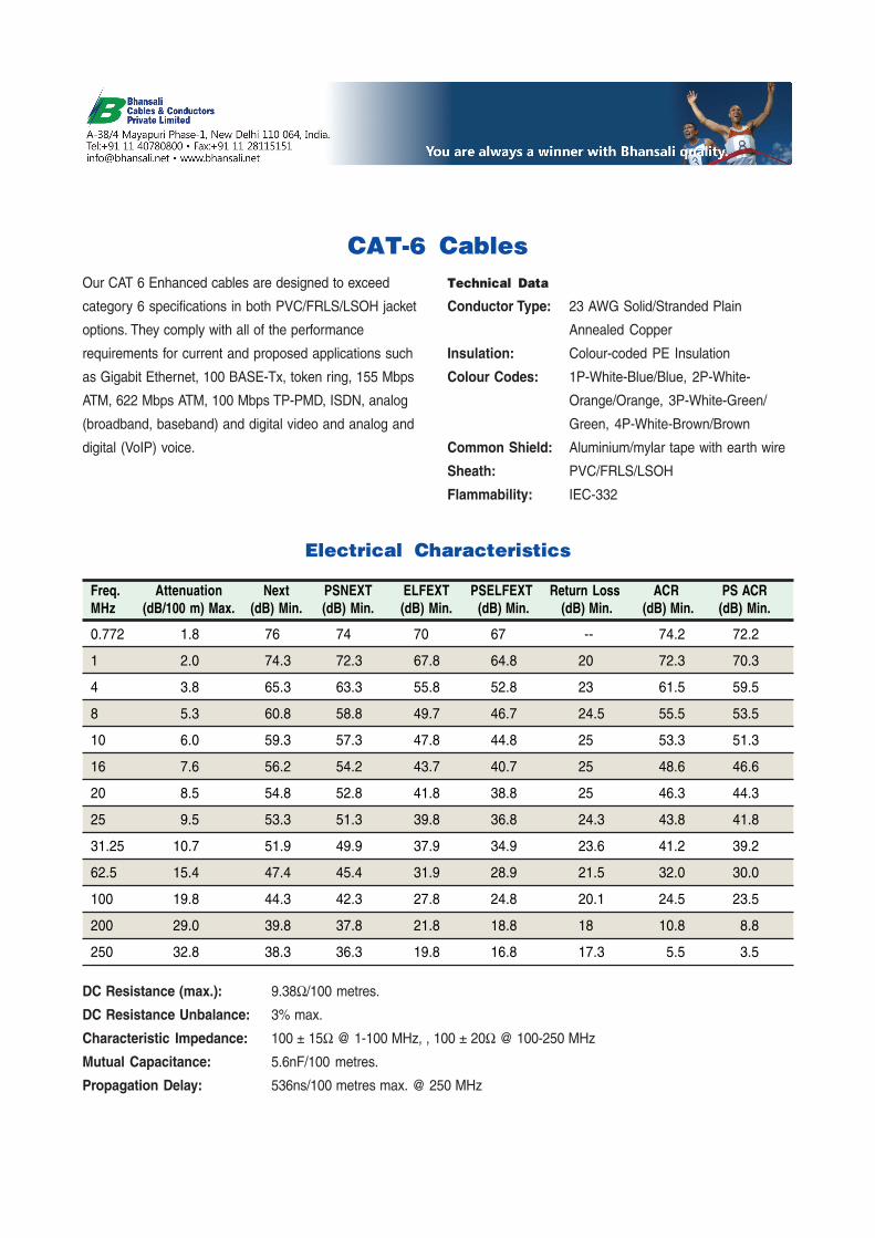
CAT-6 CablesOur CAT 6 Enhanced cables are designed to exceed
category 6 specifications in both PVC/FRLS/LSOH jacket
options. They comply with all of the performance
requirements for current and proposed applications such
as Gigabit Ethernet, 100 BASE-Tx, token ring, 155 Mbps
ATM, 622 Mbps ATM, 100 Mbps TP-PMD, ISDN, analog
(broadband, baseband) and digital video and analog and
digital (VoIP) voice.
Freq. Attenuation Next PSNEXT ELFEXT PSELFEXT Return Loss ACR PS ACRMHz (dB/100 m) Max. (dB) Min. (dB) Min. (dB) Min. (dB) Min. (dB) Min. (dB) Min. (dB) Min.
0.772 1.8 76 74 70 67 -- 74.2 72.2
1 2.0 74.3 72.3 67.8 64.8 20 72.3 70.3
4 3.8 65.3 63.3 55.8 52.8 23 61.5 59.5
8 5.3 60.8 58.8 49.7 46.7 24.5 55.5 53.5
10 6.0 59.3 57.3 47.8 44.8 25 53.3 51.3
16 7.6 56.2 54.2 43.7 40.7 25 48.6 46.6
20 8.5 54.8 52.8 41.8 38.8 25 46.3 44.3
25 9.5 53.3 51.3 39.8 36.8 24.3 43.8 41.8
31.25 10.7 51.9 49.9 37.9 34.9 23.6 41.2 39.2
62.5 15.4 47.4 45.4 31.9 28.9 21.5 32.0 30.0
100 19.8 44.3 42.3 27.8 24.8 20.1 24.5 23.5
200 29.0 39.8 37.8 21.8 18.8 18 10.8 8.8
250 32.8 38.3 36.3 19.8 16.8 17.3 5.5 3.5
Electrical Characteristics
DC Resistance (max.): 9.38Ω/100 metres.
DC Resistance Unbalance: 3% max.
Characteristic Impedance: 100 ± 15Ω @ 1-100 MHz, , 100 ± 20Ω @ 100-250 MHz
Mutual Capacitance: 5.6nF/100 metres.
Propagation Delay: 536ns/100 metres max. @ 250 MHz
Technical Data
Conductor Type: 23 AWG Solid/Stranded Plain
Annealed Copper
Insulation: Colour-coded PE Insulation
Colour Codes: 1P-White-Blue/Blue, 2P-White-
Orange/Orange, 3P-White-Green/
Green, 4P-White-Brown/Brown
Common Shield: Aluminium/mylar tape with earth wire
Sheath: PVC/FRLS/LSOH
Flammability: IEC-332

No. of Pair Min. Max. NominalPairs Config. Sheath Overall Weight
Thickness (mm) Dia.(mm) (kg/km)
2 1x2 0.6 4.5 223 1x3 0.65 5.0 314 1x4 0.5 5.8 346 1x6 0.6 6.8 50
10 1x10 0.6 8.3 7010+E 1x10 0.6 8.6 10212 1x12 0.7 9.1 9112+E 1x12 0.7 9.5 10420 1x20 0.8 10.7 14820+E 1x20 0.7 12.0 16125 1x25 0.8 11.4 17225+E 1x25 0.8 12.0 17832 4x8 0.8 12.4 21532+E 4x8 0.9 12.6 22440+E 4x10 0.9 15.0 29550+E 5x10 1.0 17.0 35260+E 6x10 1.1 20.0 41280+E 1x20 1.2 22.5 552
6x10100+E 5x20 1.4 27.0 687160+E 4x10 1.7 30.3 1069
6x20200+E 10x20 1.9 33.0 1294320+E 16x20 2.2 39.5 1755
Telephone Cables (Internal)CW 1308Used for connecting telephone systems and exchanges,these cables have a tinned copper conductor (0.5 mm dia)with PVC insulation. These are twisted to form a pair thenoversheathed in white/black/grey PVC. A rip cord is laidunder the sheath to facilitate its removal. An optional 1.38mm dia plain copper earth wire is available on 10 pair cables.
Pair No. A Wire B Wire1 WHITE-Blue BLUE-White2 WHITE-Orange ORANGE-White3 WHITE-Green GREEN-White4 WHITE-Brown BROWN-White5 WHITE-Grey GREY-WHITE6 RED-Blue BLUE-Red7 RED-Orange ORANGE-Red8 RED-Green GREEN-Red9 RED-Brown BROWN-Red10 RED-Grey GREY-Red11 BLACK-Blue BLUE-Black12 BLACK-Orange ORANGE-Black13 BLACK-Green GREEN-Black14 BLACK-Brown BRWON-Black15 BLACK-Grey GREY-Black16 YELLOW-Blue BLUE-Yellow17 YELLOW-Orange ORANGE-Yellow18 YELLOW-Green GREEN-Yellow19 YELLOW-Brown BROWN-Yellow20 YELLOW-Grey GREY-Yellow21 VIOLET-Blue BLUE-Violet22 VIOLET-Orange ORANGE-Violet23 VIOLET-Green GREEN-Violet24 VIOLET-Brown BROWN-Violet25 VIOLET-Grey GREY-Violet26 PINK-Blue BLUE-Pink27 PINK-Orange ORANGE-Pink28 PINK-Green GREEN-Pink29 PINK-Brown BROWN-Pink30 PINK-Grey GREY-Pink
COLOUR CHART FOR CW 1308&1600
CW 1308 SCREENEDThese cables are manufactured in accordance to CW 1308specifications as below with the addition of an overallaluminium foil screen and tinned copper earth wire.Available in 3, 6, 10+E, 20+E and 25+E.
No. of Pair Min. Max. NominalPairs Config. Sheath Overall Weight
Thickness (mm) Dia.(mm) (kg/km)
3 1x3 0.6 4.8 31
4 1x4 0.6 6.0 34
10+E 1x10 0.6 8.6 102
20+E 1x20 0.7 12.0 161
40+E 4x10 0.9 15.0 295
50+E 5x10 1.0 17.0 352
100+E 5x20 1.4 27.0 687
CW 1600These cables comply with British Telecom requirments forreduced fire hazard telephone cables. The conductors are0.5 mm in dia, polythylene insulated, twisted into pairs,lapped with a mica/glass tape with overall aluminiumscreen and earth wire and oversheathed with white, lowsmoke, zero halogen compound.
These cables are also available in 0.4 & 1.38

Telephone Cables (Internal)CW 1044These cables are used to provide a connection to earth ininternal telephone systems. They have plain annealedcopper conductors with a cream coloured PVC sheath.
Size Conductor Insulation Overall WeightStranding Thickness Diameter
(mm) (mm) (mm) (kg/km)
1.5 1/1.38 0.8 3.3 27
2.5 7/0.67 0.8 4.2 41
4.0 7/0.85 0.8 4.8 60
6.0 7/1.04 0.8 5.4 82
10.0 7/1.35 1.0 6.8 130
16.0 7/1.70 1.0 8.0 200
CW 1311These cables are available with 4 or 6 cores, PVCinsulated, laid up in parallel with a D cross section PVCsheath. The conductors are 7/0.15 mm tinned copperwhich makes an extremely flexible cable. Standard sheathcolours from stock: white / grey / black.
CW 1316These cables provide a convenient means of modifying orre-routing telephone installations without disturbing thedecor. The flat formation of these cables allows them to belaid under carpets without affecting the surface contour.
CW 1109This range of wires is particularly suited for the wiring ofdistribution frames and similar equipment. They are madeup of 0.5 mm soft tinned copper conductors insulated withPVC.Standard colours from stock: 2 core - Blue/Yellow, Red/
White, Black/Yellow4 core - Red/White/Green/Black
(Other colours available on request subject to minimumorder quantity)
CW 1293Conforming to British and international telecommunicationsauthorities specifications, these cables are suitable forcross-connecting individual items of switch-boardequipment and to connect the exchange with internaldistribution points.
Conductor: Solid tinned copper wire (0.5mm) to BS 4109Insulation: PVCLay-Up: Cores twisted into pairs or triples laid up to formacompact circular cable.Wrapping: Polyester clear tape.Sheath: PVC (Cream/white/grey/black). Medium to largesize cables are fitted with a nylon ripcord for easy stripping.Options: Additional earth wire either tinned or plain copperinsulated or uninsulated.
No No A-Wire B-Wire Sheath Overall Weightof Pairs of Cores Insulation Colour Insulation Co\our Thickness (mm) Dia (mm) kg/km
1 2 White Blue 0.4 3.3 102 4 White Orange 0.4 3.9 153 6 White Green 0.5 4.8 21
4 8 White Brown 0.5 5.3 305 10 White Grey 0.6 6.3 336 12 Red Blue 0.6 6.8 36
7 14 Red Orange8 16 Red Green9 18 Red Brown
10 20 Red Grey 0.6 8.3 5311 22 Black Blue12 24 Black Orange 0.7 8.6 62
These cables are also available in 0.4 & 0.9

No No A-Wire B-Wire Sheath Overall Weightof Pairs of Cores Insulation Colour Insulation Co\our Thickness (mm) Dia (mm) kg/km
13 26 Black Green
14 28 Black Brown15 30 Black Grey 0.7 9.6 7516 32 Yellow Blue
17 34 Yellow Orange18 36 Yellow Green19 38 Yellow Brown
20 40 Yellow Grey 0.7 10.4 10121 42 White/Blue Blue22 44 White/Blue Orange
23 46 White/Blue Green24 48 White/Blue Brown25 50 White/Blue Grey 0.8 11.6 117
26 52 Red/Blue Blue27 54 Red/Blue Orange28 56 Red/Blue Green
29 58 Red/Blue Brown30 60 Red/Blue Grey 0.8 12.5 15531 62 Blue/Black Blue
32 64 Blue/Black Orange33 66 Blue/Black Green34 68 Blue/Black Brown
35 70 Blue/Black Grey36 72 Yellow/Blue Blue37 74 Yellow/Blue Orange
38 76 Yellow/Blue Green39 78 Yellow/Blue Brown40 80 Yellow/Blue Grey 0.9 13.8 186
41 82 White/Orange Blue42 84 White/Orange Orange43 86 White/Orange Green
44 88 White/Orange Brown45 90 White/Orange Grey46 92 Orange/Red Blue
47 94 Orange/Red Orange48 96 Orange/Red Green49 98 Orange/Red Brown
50 100 Orange/Red Grey 0.9 14.1 23051 102 Orange/Black Blue52 104 Orange/Black Orange
53 106 Orange/Black Green54 108 Orange/Black Brown
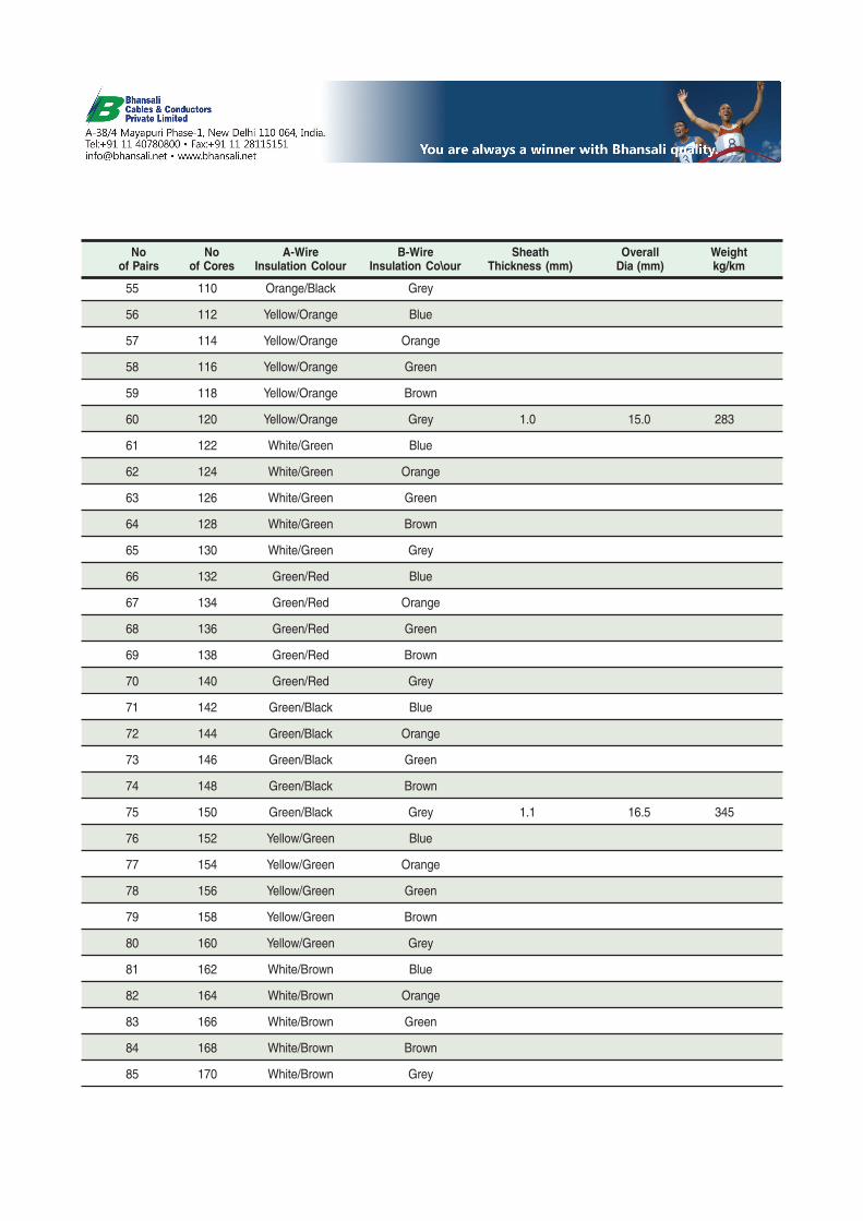
No No A-Wire B-Wire Sheath Overall Weightof Pairs of Cores Insulation Colour Insulation Co\our Thickness (mm) Dia (mm) kg/km
55 110 Orange/Black Grey
56 112 Yellow/Orange Blue
57 114 Yellow/Orange Orange
58 116 Yellow/Orange Green
59 118 Yellow/Orange Brown
60 120 Yellow/Orange Grey 1.0 15.0 283
61 122 White/Green Blue
62 124 White/Green Orange
63 126 White/Green Green
64 128 White/Green Brown
65 130 White/Green Grey
66 132 Green/Red Blue
67 134 Green/Red Orange
68 136 Green/Red Green
69 138 Green/Red Brown
70 140 Green/Red Grey
71 142 Green/Black Blue
72 144 Green/Black Orange
73 146 Green/Black Green
74 148 Green/Black Brown
75 150 Green/Black Grey 1.1 16.5 345
76 152 Yellow/Green Blue
77 154 Yellow/Green Orange
78 156 Yellow/Green Green
79 158 Yellow/Green Brown
80 160 Yellow/Green Grey
81 162 White/Brown Blue
82 164 White/Brown Orange
83 166 White/Brown Green
84 168 White/Brown Brown
85 170 White/Brown Grey

No No A-Wire B-Wire Sheath Overall Weightof Pairs of Cores Insulation Colour Insulation Co\our Thickness (mm) Dia (mm) kg/km
86 172 Red/Brown Blue
87 174 Red/Brown Orange
88 176 Red/Brown Green
89 178 Red/Brown Brown
90 180 Red/Brown Grey
91 182 Brown/Black Blue
92 184 Brown/Black Orange
93 186 Brown/Black Green
94 188 Brown/Black Brown
95 190 Brown/Black Grey
96 192 Yellow/Brown Blue
97 194 Yellow/Brown Orange
98 196 Yellow/Brown Green
99 198 Yellow/Brown Brown
100 200 Yellow/Brown Grey 1.2 20.1 432

Telephone Cables (External)CW 1128These cables are used in external environments forprotection against moisture. Made with plain coppercondutors 0.5 mm in diameter. Polyethylene insulated,twisted into pairs and laid in unit construction. They arethen filled with petroleum jelly and polythethylene sheathedin black.
CW 1198These cables are used in external environments where agreater degree of mechanical protection is required.Construction is as per CW 1128 with the addition of agalvanised steel wire armour and polyethylene oversheath.
No of Conductor Dia of Min Sheath Max NominalPairs Size (mm) Armour Thickness Overall Dia Weight
Wire (mm) (mm) (mm) (kg/km)
2 0.5 0.9 0.9 12.7 170
5 0.5 0.9 0.9 13.2 240
10 0.5 0.9 0.9 14.7 295
20 0.5 0.9 0.9 17.2 380
30 0.5 1.25 0.9 20.2 495
50 0.5 1.6 1.0 23.3 880
100 0.5 1.6 1.1 29.0 1310
No of Conductor Min Sheath Max Overall NominalPairs Size (mm) Thickness Dia (mm) Weight
(mm) (kg/km)
2 0.5 1.1 7.5 60
5 0.5 1.1 8.0 100
10 0.5 1.1 9.5 145
20 0.5 1.1 12.0 280
30 0.5 1.2 14.3 355
50 0.5 1.2 16.5 470
100 0.5 1.3 22.0 745
2 0.9 1.1 9.0 107
5 0.9 1.2 11.5 255CW 1252These cables are self-supporting for aerial installations.Construction as per CW 1128 with the inclusion of anintegral steel support strand or caternary. The crosssection of these cables resembles a figure of eight.
No of Conductor No and Max Overall WeightPairs Size (mm) Nominal Dia Dia (mm) (kg/km)
of Strands (mm)
5 0.5 1/2.65 8.1 125
10 0.5 1/2.65 9.0 150
20 0.5 7/1.6 11.1 210
30 0.5 7/1.6 13.0 350
50 0.5 7/1.6 15.6 470
100 0.5 7/1.6 20.4 740
CW 1128
CW 1198
CW 1252
CW 1236These cables are made from plain copper conductors,cellular polyethylene insulated, twisted into pairs and laidup in unit formation. An aluminium moisture barrier isbonded to a black solid outer polyethylene outer sheathand then petroleum jelly filled. (Over 200 pairs only).
Unit No. 1 2 3 4 5
Pair No 1-10 11-20 21-30 31-40 41-50
Colours BLUE ORANGE GREEN BROWN GREY
Unit No. 1 2 3 4 5
Pair No 51-60 61-70 71-80 81-90 91-100
Colours WHITE RED BLACK YELLOW VIOLET
Colour of Tape Lappings
Pair No. A Wire B Wire1 WHITE BLUE2 WHITE ORANGE3 WHITE GREEN4 WHITE BROWN5 WHITE GREY6 RED BLUE7 RED ORANGE8 RED GREEN9 RED BROWN10 RED GREY
COLOUR CHART
These cables are also available in 0.4, 0.6 & 0.63

BT 2001 BT 2002 BT 2003 BT 3001 BT 3002*
CCF 75/60 CCF 75/61 CCF 75/62 CCF 75/63 CCS 75/64 CCS 75/65
CONSTRUCTION
Inner Conductor 7/0.2 7/0.2 1/0.61 1/0.40 1/0.31 1/0.23
Size (mm) Cu Cu Cu Cu Cu Cu
Material Dielectric Size (mm) 2.45 2.50 3.7 1.75 1.95 1.5
Material FPE FPE PE FPE PE PE
Outer Conductor
1 Cu Br Cu Br Cu Br Al/Pt TCu Br Cu Br
2 Cu Br Cu Br TCu Br TCu Br
Outer Sheath
Approx OD (mm) 4.40 5.10 6.70 3.60 3.55 2.80
Material PVC PVC PVC PVC PVC PVC
Approx. Weight
(kg/km) 37 66 104 21 30 18
ELECTRICAL DATA
Impedance (Ω) 75 75 75 75 75 75
Capacitance
Approx. pF/m 56.7 56.7 68.5 58 58 67
Velocity Ratio (%) 78 78 66 78 66 66
Attenuation (dB/100m) at:
1 mHz 1.26 1.26 1.0 2.1 2.5
4 mHz 5.0
5 mHz 4.0 4.0 2.6 4.8 4.8
17 mHz 11.0
67 mHz 9.0
70 mHz 22.0
* BT 3002 can also be offered in multi-core versions.Cu - Copper, TCu - Tinned Copper, CuW - Copper Weld, Br - Braid, Al/Pt - Aluminium/PET Tape, PE - Polyethylene,FPE - Foam Polyethylene, PVC - Polyvinyl Chloride
Miniature Single and Multi-core Coaxial Cables
for Transmission Equipment (BT Specifications)

No No A-Wire B-Wire Sheath Overall Weightof Pairs of Cores Insulation Colour Insulation Co\our Thickness (mm) Dia (mm) kg/km
1 2 White Blue
2 4 White Orange 1.3 6.8 55
3 6 White Green 1.3 6.9 55
4 8 White Brown
5 10 White Grey 1.5 9.3 100
6 12 Red Blue 1.5 9.3 120
7 14 Red Orange
8 16 Red Green
9 18 Red Brown
10 20 Red Grey 1.5 9.3 120
20 40 1.5 13.4 240
30 60 1.5 15.2 330
40 80 1.5 16.9 400
50 100 1.5 18.4 490
60 120 1.5 19.7 570
70 140 1.5 21.0 650
100 200 1.5 24.3 860
Elaky Cable for Data Transmission and
Local Network Distribution
Conductor: Solid, plain annealed copper to BS 4109Insulation: PVC to BS 6234Lay-Up: Two, insulated conductors, twisted to form a pair.Cable, 5-10 pairs:Required number of pairs are stranded together to form acompact circular cable.Cable, 20-100 pairs:Required number of 10-pair units are laid up together toform a compact circular cable. Each unit is identified by adifferent colour binder.
Wrapping: Polyester or polyethylene tapes are tapedaround the cable for isolation.Screening: Copper tape lapped with overlap. Nominalthickness of tape is 0.05 mm. Two plain copper earth wires(0.6 mm) are laid longitudinally under the copper tape.Polyester tape overall.Sheath: PVC to BS 6746 (black / grey)
Conductor diameter: 0.6 mmInsulation thickness: 0.24 mmInsulation diameter: 1.08 mmConductor Resistance at 20º C (Ω/km): 65Insulation Resistance (MΩ/km): 5,000Capacitance Unbalance (pF) for 500 m: 100

No No Numbered Sheath Overallof Pairs of Cores Tape Thickness (mm) nominal Dia (mm) max.
1 2 1 0.8 4.8
2 4 2 0.8
3 6 3 0.8
4 8 4 0.8
5 10 5 0.8
6 12 6 1.0
7 14 7 1.0
8 16 8 1.0
9 18 9 1.0
10 20 10 1.0 14.4
11 22 11 1.4
12 24 12 1.4
13 26 13 1.4
14 28 14 1.4
15 30 15 1.4
16 32 16 1.4 17.0
120 ΩΩΩΩΩ Balanced PCM Cables forTransmission Equipment Installation
As per Alcatel Specifications
Conductor: Solid, plain annealed copper to IEC 60228Insulation: Foam PE.Pair Colour: A Wire - Red, B Wire - BlueLay-Up: Two, insulated conductors, twisted to form a pair.Screened with numbered Aluminium mylar tape with 0.5mm ATC earth wire. Required number of pairs are strandedtogether to form a compact circular cable.Wrapping: Polyester or polyethylene tapes are taped
around the cable for isolation.Screening: Aluminium mylar tape lapped with overlap.Nominal thickness of tape is 0.05 mm with earth wire (0.5mm ATC).Braiding: 0.15 mm ATC braiding with minimum coverageof 30% and 35-40º braid angle.Sheath: PVC (grey) ST grade.
Conductor diameter: 0.5 mmInsulation diameter: 1.35 mm (max.)Conductor Resistance (Loop) at 20º C (Ω/km): 187.9Insulation Resistance (MΩ/km): 5,000Capacitance Unbalance Pair to Ground (pF) for 500 m: 2000Impedance (Ω): 120±10Resistance Unbalance: 2.5% max.Cross talk: 70 dB for 500 m.

No No Conductor Conductor Overall Conductor Insulation Weightof Pairs of Cores Cross-Section Insulation Dia (mm) Resistance Resistance
Area (mm²) Thickness (mm) at 20° C (ΩΩΩΩΩ/km) (MΩΩΩΩΩ/km) (kg/km)
Dropwire No 11 2 0.65 0.76 2.7x5.6 48 50 16
Dropwire No 21 2 1.02 1.52 4.44x9.4 62 50 72
Dropwire No 61 2 0.52 0.76 2.5x5.4 122 50 15
Dropwire No 81 2 1.02 1.52 4.44x9.4 21.5 24 72
Dropwire No 10A12 4 0.2 0.25 5.5 93.0 50 32
Dropwire No 1, 2, 6, 8 & 10A
No Conductor Conductor Conductor Insulation Conductor Insulation Weightof Cores diameter Cross-Section Insulation Dia (mm) Resistance Resistance
(mm) Area (mm²) Thickness (mm) at 20° C (ΩΩΩΩΩ/km) (MΩΩΩΩΩ/km) (kg/km)
1 0.4 0.126 0.2 0.85 150.0 50 1.651 0.5 0.20 0.2 0.95 97.5 50 2.401 0.6 0.28 0.2 1.05 65.0 50 3.201 0.9 0.64 0.25 1.6 29.0 50 7.002 0.6 0.28 0.2 2.0 65.0 50 3.433 0.6 0.28 0.2 2.2 65.0 50 5.454 0.6 0.28 0.2 2.4 65.0 50 7.405 0.6 0.28 0.2 2.6 65.0 50 9.20
Equipment Wires & Jumper Wires CW 1257Equipment wires and jumper wires are utilised for crossconnections on instrumentent panels and throughoutindustry on all types of electronic equipment.
Construction
Conductor: Solid tinned copper wire to BS 4109
Insulation: PVC to BS 6746
Options: Single or bi-colours
Options: Jumper wires are available in stranded conductors.

RG type RG-11 RG-6 RG-6Foam Air Spaced
Conductor ABC ABC ABC
Dia (mm) 1.63 1.02 1.00
Dia over dielectric (mm) 7.10 4.57 4.35
Shield Al Foil + Braid Al Foil + Braid Al Foil+ Braid
Over all dia (mm) 10.00 6.90 6.45
Min. bending radius (mm) 140 100 100
Impedance (Ω) 75 75 75
DC Resistance (Ω/km) 8.60 21.11 23.05
CATV Coaxial Cables
RG-111.63 mm solid plain copper conductor, foam PE insulated,Al-foil bounded, ATC/Al PVC/PE sheathed, for use in cableTV applications.
RG-6 (Foam)1.02 mm solid plain copper conductor, foam PE insulated,Al-foil bounded, ATC/Al PVC/PE sheathed, for use in cableTV applications.
RG-6 (Air Spaced)1.00 mm solid plain copper conductor, foam PE insulated,Al-foil bounded, APC PVC/PE sheathed, for use in cableTV applications.

Digital Distribution Frame (DDF)
SCOPEDDF is widely used in telecommunication sectors as apassive device that terminates cables, allowing arbitraryinterconnections to be made.
TYPE
120 Ohm DDF module (balanced)
Used for terminating, distributing and cross patching 2 Mbcircuits coming from/going to S/W systems, primarymultiplexers, cabling systems, distant signaling systemsor multiplexers. It provides facilities of termination ofincoming and outgoing 2 Mb circuits, testing, isolation andcross patching the I/C and O/G termination cables withoutneed for changing wrapping of I/C and O/G cables.
Therefore 2Mb DDF module provides flexibility of designin S/W and /or transmission room and provides easymonitoring of 2Mb circuits.
75 Ohm DDF module (Unbalanced)
Used for terminating, distributing and cross patching 8,34,45,140 or 155 Mb circuits (as the case may be) from andto higher order multiplex equipment. This module providesfacility of termination, testing, isolation and self loop of 8/34/45/140/155 Mb circuits and therefore provides easymonitoring of 8/34/45/140/155 Mb circuits.
Bay frame or Slim Rack
Used for termination all type of modules as describedabove The capacity of bay frame is to mount 8 nos. of anycombination of digital distribution modules.

Cable Assemblies
We offer a variety of cable assemblies for the
telecommunications industry. We bring together our
experience in cable manufacturing, system cabling
and connectors to provide regular and custom-made
assemblies.
Our range includes cable assemblies for transmission
equipment, BTS, antenna, GPS systems, power
integration units and a variety of other applications.

Enquiry FormSpecial-purpose CablesCable Preparation
Please refer to the abbreviated specifications for the important point requiredfor elaborating a quotation for special-purpose cable system.
It will be far easier to process your enquiry if you enclose a drawing andspecification including electrical & physical properties if any.
You can detach the enquiry form and send it to us with this information.
Quantity Size Cable Type
Intended application How is the cable laid?
What thermal and mechanical requirements are made of the cable?
Make-up
Strands (wires x mm) Core Core
Wire (mm²)
Copper bare/tinned/silver-plated Copper bare/tinned/silver-plated
Insulation PVC/PE/FPE rubber/silicone/PTFE/PUR PVC/PE/FPE rubber/silicone/PTFE/PUR
Screening (if required) Copper bare/tinned braided Copper bare/tinned braided
Al Foil/Cu Foil Al Foil/Cu Foil
drain wire, bare/tinned mm drain wire, bare/tinned mm
Further cores
Core colour Support element: Messenger wire/galvanized steel
Inner sheath: PVC/rubber/silicone Common screen: ABC/ATC/SPC/Al Foil
Braiding % dia over braid approx metal foil with/without Armouring: steel wire
Sheath wire mm Copper bare/tinned
Outer sheath: PVC/PE/silicone/neoprene/rubber/PUR Outer dia approx mm
Electrical properties
Operating voltage Test voltage Capacitance
Other information Delivery date
Sender:
Name: Road/Street/PO Box
Company: Town/City
Department: Postal Code
Designation Fax
Telephone E-mail
Sign/stamp Date
Note:

B BhansaliCables & ConductorsPrivate Limited
Marketing OfficeA-38/4 Mayapuri Phase I, New Delhi 110 064, India.
Tel: +91 11 40780800 • Fax: +91 11 [email protected] • www.bhansali.net
ABB Alcatel Alstom Ascom Bharti Airtel Bose BSNL
Ericsson Fujitsu GTL Marconi Motorola MTNL Nelco
NHPC Nokia NTPC Reliance Siemens Simoco
Tata Honeywell Tata Steel Tata Teleservices Tyco Electronics
•
• • • • • •
• • • • •
• • •
• • • • •
Some Bhansali Customers
ISO 9001:2000 • ISO 14001:2004
Certifications


![Template (Unscreened Aircraft Operators): Developing a TSP€¦ · Web view[report/investigate etc.] security breaches, threats or aviation incident reports for ... will ensure](https://static.fdocuments.in/doc/165x107/5e3c6c73e8dde05abd027be8/template-unscreened-aircraft-operators-developing-a-tsp-web-view-reportinvestigate.jpg)


![Mixed-ADC/DAC Multipair Massive MIMO Relaying Systems ...oa.ee.tsinghua.edu.cn/dailinglong/publications/paper...recently, Kong et al. [25], Dong et al. [26], Liu et al. [27], Kong](https://static.fdocuments.in/doc/165x107/607b0f5be49c6d5d27220236/mixed-adcdac-multipair-massive-mimo-relaying-systems-oaee-recently-kong.jpg)