Y.K. Lee 1, S.C.Rho2, Y.J - Railway Research · The high power active filter system for harmonic...
6
The high power active filter system for harmonic compensation of electric railway Y.K. Lee 1 , S.C.Rho 2 , Y.J.Jeon 1 1 Korea Railroad Corporation, Daejeon, South Korea; 2 Korea National Railroad College, Uiwang, South Korea Abstract At present, harmonic currents cause serious problems in power conversion system using the semiconductor switching device. Also some of the conversion system provokes harmonic currents against to the main power supply system and causes hindrances for the system. Main power impedance of the traditional LC passive filter method, influences on the filter characteristics and amplifies the harmonics when resonance phenomenon is occurred. And the traditional existing 2 level inverter systems show the limit in capacity of voltage and current in case of occurring sudden load change. So, to solve this problem active filter which uses cascaded H-bridge multi level inverter has been designed and ex-filter system circuits were totally investigated. With multi level active filtering system not only the size of filter but also the size of filter fore transformer can be reduced by half and so as to the weight, while the capacity of inverter can be double sized and wave forms can be compensated exactly and precisely. Also by the benefit of the increase in rating capacity, the various currents owing to the load fluctuation can be dealt more steadily. In order to simulate the wave form of harmonics based on the measured data on the AC 25kV high speed Domestic Commercial railway, it was simulated with PSCAD/EMTDC and PSIM. Based on the results of this demonstration, the power supply system and inverter system would be more stable and also promoting its efficiency. 1. Introduction Because of frequent installation of power conversion equipment, the harmonic problem restricts other electrical components part and has a bad influence on the power quality. According to the development of power conversion equipment, PWM type is general trend in these days and Power quality is quite improved when it compares with SCR type which was used before . But in railway, the harmonics are unavoidable due to the frequent powering and regenerating of electric rail car.[2,3] To get rid of the harmonics from the power system and increase power quality, research for the filter system is very popular lately. Especially active filters are most common method. The principle of this filter is to analyze the ingredients of harmonics and input the opposite phase of the same dimension of harmonics to the power system; finally the harmonics included in the system can be removed.[4,5,6] Active filters can be divided as serial connection to load type (voltage source type), parallel connection to load type (current source type), compound connection to load type (hybrid type).[2,8] The latter type is the most complex to materialize but it proved its appropriateness, so we applied into our own system. In this paper we analyzed Korea high speed railway power system to evaluate harmonics and to design effective active filter. Multi level H-bridge cascade type filter was proposed and verified through the simulation. 2. Design background of filter 2.1 Equivalent model and Harmonic condition for electrical railway feeding system In order to analyze harmonic currents and design a filtering system to be able to decrease harmonic currents modeling of the system through the equivalent conversion of the commercial line was preceded. The most representative components like Scott-transformer (MTr), Auto-Transformer (AT), distribution line etc. were modeled with the parameters as below in table 1. In order to improve accuracy the values of parameters were measured on site. Fig1. shows the electrical equivalent model for the object. Four ATs are installed on both direction lines (up and down)by 10kms.
Transcript of Y.K. Lee 1, S.C.Rho2, Y.J - Railway Research · The high power active filter system for harmonic...

The high power active filter system for harmonic compensation of electric railway
Y.K. Lee1, S.C.Rho2, Y.J.Jeon1
1Korea Railroad Corporation, Daejeon, South Korea; 2Korea National Railroad College, Uiwang, South
Korea
Abstract
At present, harmonic currents cause serious problems in power conversion system using the semiconductor switching device. Also some of the conversion system provokes harmonic currents against to the main power supply system and causes hindrances for the system. Main power impedance of the traditional LC passive filter method, influences on the filter characteristics and amplifies the harmonics when resonance phenomenon is occurred. And the traditional existing 2 level inverter systems show the limit in capacity of voltage and current in case of occurring sudden load change. So, to solve this problem active filter which uses cascaded H-bridge multi level inverter has been designed and ex-filter system circuits were totally investigated. With multi level active filtering system not only the size of filter but also the size of filter fore transformer can be reduced by half and so as to the weight, while the capacity of inverter can be double sized and wave forms can be compensated exactly and precisely. Also by the benefit of the increase in rating capacity, the various currents owing to the load fluctuation can be dealt more steadily. In order to simulate the wave form of harmonics based on the measured data on the AC 25kV high speed Domestic Commercial railway, it was simulated with PSCAD/EMTDC and PSIM. Based on the results of this demonstration, the power supply system and inverter system would be more stable and also promoting its efficiency.
1. Introduction
Because of frequent installation of power conversion equipment, the harmonic problem restricts other electrical components part and has a bad influence on the power quality. According to the development of power conversion equipment, PWM type is general trend in these days and Power quality is quite improved when it compares with SCR type which was used before . But in railway, the harmonics are unavoidable due to the frequent powering and regenerating of electric rail car.[2,3] To get rid of the harmonics from the power system and increase power quality, research for the filter system is very popular lately. Especially active filters are most common method. The principle of this filter is to analyze the ingredients of harmonics and input the opposite phase of the same dimension of harmonics to the power system; finally the harmonics included in the system can be removed.[4,5,6] Active filters can be divided as serial connection to load type (voltage source type), parallel connection to load type (current source type), compound connection to load type (hybrid type).[2,8] The latter type is the most complex to materialize but it proved its appropriateness, so we applied into our own system. In this paper we analyzed Korea high speed railway power system to evaluate harmonics and to design effective active filter. Multi level H-bridge cascade type filter was proposed and verified through the simulation.
2. Design background of filter 2.1 Equivalent model and Harmonic condition for electrical railway feeding system
In order to analyze harmonic currents and design a filtering system to be able to decrease harmonic currents modeling of the system through the equivalent conversion of the commercial line was preceded. The most representative components like Scott-transformer (MTr), Auto-Transformer (AT), distribution line etc. were modeled with the parameters as below in table 1. In order to improve accuracy the values of parameters were measured on site. Fig1. shows the electrical equivalent model for the object. Four ATs are installed on both direction lines (up and down)by 10kms.

To measure the harmonic wave, the test train was operated with follow conditions: Half set (10 cars) of High speed train was operated with six traction motors and one PC. Fig2. shows the waveform of the catenary voltage and current before test train is operated. Parameters which are not mentioned above will be decided by the reference documents[1]
Classification Data Remark rated voltage 154 [ ] Supplier
power system positive phase impedance 0.287+j2.837 [%] 100MVA base Overhead 0.0567+j0.2079 [%] line positive phase
impedance Under ground 0.0257+j0.1196 [%] 100MVA base [ ]unit
Overhead 0.134 [ ] Power Transmission line
Length Under ground 3.559 [ ]
rated voltage 154/55 [ ] rated capacity 30/40 [MVA] Main Transformer Impedance 10 [%] 30MVA base
Catenary 0.12 +j0.30[Ω/km] Rail 0.04 +j0.12[Ω/km] Feeder line 0.14 +j0.45[Ω/km]
Table 1 Parameters for the object system
Fig1. Equivalent models for the object system Fig2. Substation no load voltage profile Fig3. shows the measured data while test train under operation and Fig4. is the result for FFT. According to the result 5th, 7th, 11th harmonic was highly generated and this is similar to single phase control rectifier system with passive filter.
Fig3. Voltage and current measured data Fig4. FFT Harmonic profile

2.2 Proposed filter
High speed train which runs in korea(KTX) uses thyristor type phase controller and it has high possibility to inject harmonic currents to the source system. There for filters to remove harmonics are necessary. In the past, passive filter was most famous method but development of power transfer elements, active filters become generalized these days. Recently, the various research of hybrid type which combines passive and active filter are lively because of cost benefit. Active filter which use H-bridge type multi level inverter was proposed because of advantages like few components, less inductance between switch and capacitor, simple design and free from voltage unbalance. [7] The low level harmonic currents are restricted by using PWM control algorithm. And an additional LC passive filter in front of input circuit will restrain 3 rd, 5th of the harmonics. Finally Cascaded H Bridge type active filter was installed parallel to the passive filter. Fig5. shows installation concept diagram of the compensation system which composed of three section such as substation, feeder section and compensation filter.
AC
Substation FeederSection
CompensationSystem
Train Load
PassiveFilter
ActiveFilter
Fig5. Concept diagram for compensation system Fig6. shows the connection diagram for the cascaded H-Bridge inverter type active filter and voltage, current output profile.
Fig6. Active filter diagram and output profile
A passive filter parameter was designed in order to remove 3 rd, 5th harmonics on the basis of the harmonic characteristic graph. There for the stability of the system will be increased.
2.3 Control design
Most of multi level inverter PWM type uses SVPWM control algorithm because it is useful to control harmonic current in normal condition. But when output level increases, it is difficult to distinguish each vector and control diagram becomes complicated. Through the measured data in the commercial railway lines and composition of the system, it is highly recommended that multi carry PWM control type is proper method than SVPWM control type. The strength points of multi carrier types are as follows: it is easy and simple to control, the carry which is one less than the degree of voltage level is required and each carry signal produces switching waveform
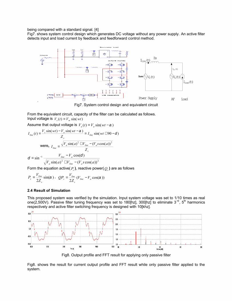
being compared with a standard signal. [4] Fig7. shows system control design which generates DC voltage without any power supply. An active filter detects input and load current by feedback and feedforward control method.
.
Source
Zs
Iinv(t)
ILine(t)
ILoad(t)Vs(t) Va(t)
Power Supply AF Load Fig7. System control design and equivalent circuit
From the equivalent circuit, capacity of the filter can be calculated as follows. Input voltage is )sin()( wtVtV ms = Assume that output voltage is )sin()( α−= wtVtV aa
)90sin()sin()sin(
)( δα
−+=−−
= wtIZ
wtVwtVtI line
s
asline
were, s
alinealine Z
asVVaVI
22 ))cos(()sin( −+=
22
1
))cos(()sin(
)cos(sin
asVVaV
VV
alinea
aline
−+
−= − δ
δ
Form the equation active( sP ), reactive power( sQ ) are as follows
)sin(2
αs
lines Z
VP = , ))cos((2
αalines
lines VV
ZVQP −=
2.4 Result of Simulation
This proposed system was verified by the simulation. Input system voltage was set to 1/10 times as real one(2,500V). Passive filter tuning frequency was set to 180[hz], 300[hz] to eliminate 3 rd, 5th harmonics respectively and active filter switching frequency is designed with 10[khz].
Fig8. Output profile and FFT result for applying only passive filter
Fig8. shows the result for current output profile and FFT result while only passive filter applied to the system.

Compare to original FFT graph harmonics are generally reduced, especially 3 rd, 5th harmonics are clearly decreased. Fig9. shows the result when proposed filter was applied to the system. The measured data are as follows: i nput voltage was set to 2,500[v], maximum load current is up to 193.6[A], active filter maximum compensation current is 150[A], Input current is 149.5[A]. According to the result, only 0.4[A] of 3rd harmonic current is observed when basic frequency current is 148.3[A]. The result shows filter and algorithm is properly designed and applied.
Fig9. Output profile and FFT result for applying filter system Meanwhile, compare 2 level inverter to multi level inverter, the former voltage amplitude is bigger than the latter at same capacity, there for the size of 2 level inverter transformer is big. Fig 10. shows the voltage profiles per switch for 2 level and multi level inverter. The result shows that the voltage magnitude of 2 level inverter is twice bigger than multi level inverter.
Fig10. Output voltage profile for 2 level and multi level inverter
3. Conclusion
In this paper H Bridge Cascaded type active filter was studied to improve power quality in power system of Korea high speed railway (KTX). The KTX with the Phase control thyrister type power converter breaks out a lot of harmonic currents. In order to reduce harmonic current more effectively than ex-filter type, the hybrid type using both an active and passive filer of H Bridge cascaded type at the same time was applied in parallel. This applied system was verified by PSCAD/EMTDC, PSIM simulation program and the result shows that harmonic currents were strongly eliminated and voltage per each switch was reduced by half compared to that used before. The prototype product for hybrid filter is under manufacturing at present. In the near future, the proposed system will be tested on the commercial line to prove stability and performance efficiency.
4. References
[1] Korea Railroad Research Institute “Improvement Measures of Power Quality on Seoul-Taegu Line in Kyung-Bu High Speed Railway(I), (II), (III)”, Korea Train Express report. (2002, 2003, 2004).
[2] Mark McGranaghan, “ Active Filter Design and Specification for control of harmonics in industrial and commercial facilities” , Electrotek concepts, Inc., Knoxville TN, USA.

[3] Routimo, M., Salo, M. & Tuusa, "Improving the active Power filter performance with A Prediction based reference generation" NORPIE/2004, Nordic Workshop on Power and Industrial Electronics, 14-16 June 2004, Trondheim, Norway. 6 p.
[4] Xiaoming Yuan; Merk, W.; Stemmler, H.; Allmeling, J., "Stationary-frame generalized integrators for current control of active power filters with zero steady-state error for current harmonics of concern under unbalanced and distorted operating conditions", Industry Applications, IEEE Transactions on Volume 38, Issue 2, March-April 2002 Page(s):523 - 532
[5] Ingram, D.M.E.; Round, S.D., "A novel digital hysteresis current controller for an active power filter" Power Electronics and Drive Systems, 1997. Proceedings., 1997 International Conference on Volume 2, 26-29 May 1997 Page(s):744 - 749 vol.2
[6] Mika Salo, "A Current-Source Active Power Filter with a New DC Filter Structure", Department of Electrical Engineering, Institute of Power Electronics. Tampere University of Technology.
[7] Mario Marchesoni, Maurizio Mazzucchelli, Sandro Tenconi. “A Nonconventional Power Converter for Plasma Stabilization” IEEE Transactions on Power Electronics. Vol., 5. No. 2, April 1990.
[8] Juan W. Dixon, Gustavo Venegas, and Luis A. Moran, “ A Series Active Power Filter Based on a sinusoidal Current-Controlled Voltage-Source Inverter” IEEE Transaction on Industrial Electronics, Vol., 44, No. 5, October 1997.


![pdfs.semanticscholar.orgpdfs.semanticscholar.org/f6ed/527c8e16d27167fc0192a27b5bbae1… · improve the original manuscript. Y.J. is grateful to Xiaoqiang Zhao for insightful [4] [12]](https://static.fdocuments.in/doc/165x107/5f268acfd427ff40e32e7a05/pdfs-improve-the-original-manuscript-yj-is-grateful-to-xiaoqiang-zhao-for-insightful.jpg)