Yellow Point - PWB Anchor · NEVER EXCEED PUBLISHED WORKING LOAD LIMIT WARNING YOKE Yellow Point...
36
Yellow Point Catalog No. 8-2015.YP.2
-
Upload
phungtuyen -
Category
Documents
-
view
232 -
download
0
Transcript of Yellow Point - PWB Anchor · NEVER EXCEED PUBLISHED WORKING LOAD LIMIT WARNING YOKE Yellow Point...
Yellow Point
Catalog No. 8-2015.YP.2
2
3

NEVER EXCEED PUBLISHED WORKING LOAD LIMITWARNING
Copyright © 2015YOKE Industrial Corp.
All Rights Reserved.
YOKE Yellow Point Series
TM
4
NEVER EXCEED PUBLISHED WORKING LOAD LIMITWARNING
Copyright © 2015YOKE Industrial Corp.All Rights Reserved.
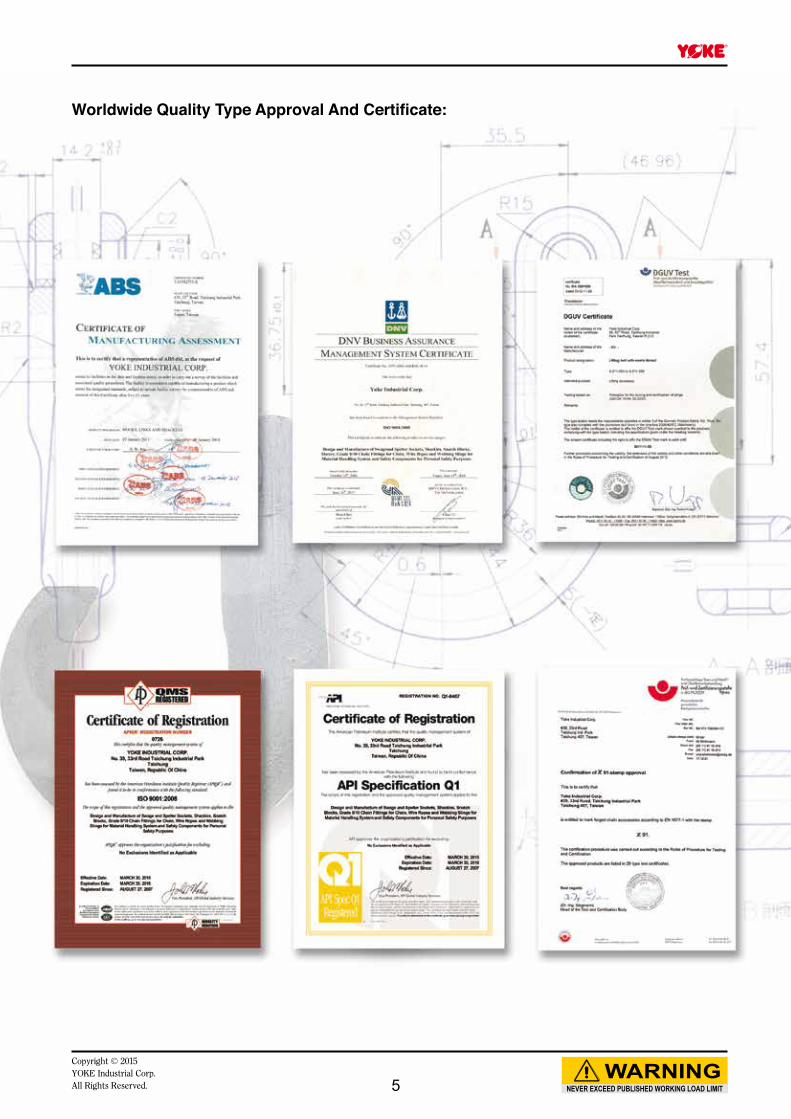
Worldwide Quality Type Approval And Certificate:
5
NEVER EXCEED PUBLISHED WORKING LOAD LIMITWARNING
Copyright © 2015YOKE Industrial Corp.
All Rights Reserved.
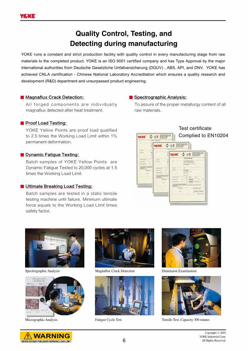
■■ Magnaflux■Crack■Detection:■
Al l forged components are ind iv idual ly
magnaflux detected after heat treatment.
■■ Proof■Load■Testing:■
YOKE Yellow Points are proof load qualified
to 2.5 times the Working Load Limit within 1%
permanent deformation.
■■ Dynamic■Fatigue■Testing:■
Batch samples of YOKE Yellow Points are
Dynamic Fatigue Tested to 20,000 cycles at 1.5
times the Working Load Limit.
■■ Ultimate■Breaking■Load■Testing:
Batch samples are tested in a static tensile
testing machine until failure. Minimum ultimate
force equals to the Working Load Limit times
safety factor.
■■ Spectrographic■Analysis:
To assure of the proper metallurgy content of all
raw materials.
Quality Control, Testing, and Detecting during manufacturing
YOKE runs a constant and strict production facility with quality control in every manufacturing stage from raw
materials to the completed product. YOKE is an ISO 9001 certified company and has Type Approval by the major
international authorities from Deutsche Gesetzliche Unfallversicherung (DGUV) , ABS, API, and DNV. YOKE has
achieved CNLA certification - Chinese National Laboratory Accreditation which ensures a quality research and
development (R&D) department and unsurpassed product engineering.
Test certificateComplied to EN10204
Spectrographic Analysis
Micrographic Analysis
Magnaflux Crack Detection
Fatigue Cycle Test
Dimension Examination
Tensile Test, Capacity 300 tonnes
6
NEVER EXCEED PUBLISHED WORKING LOAD LIMITWARNING
Copyright © 2015YOKE Industrial Corp.All Rights Reserved.
P12
P26
P28
P29
P30
P14
P18
P16
P22
P20
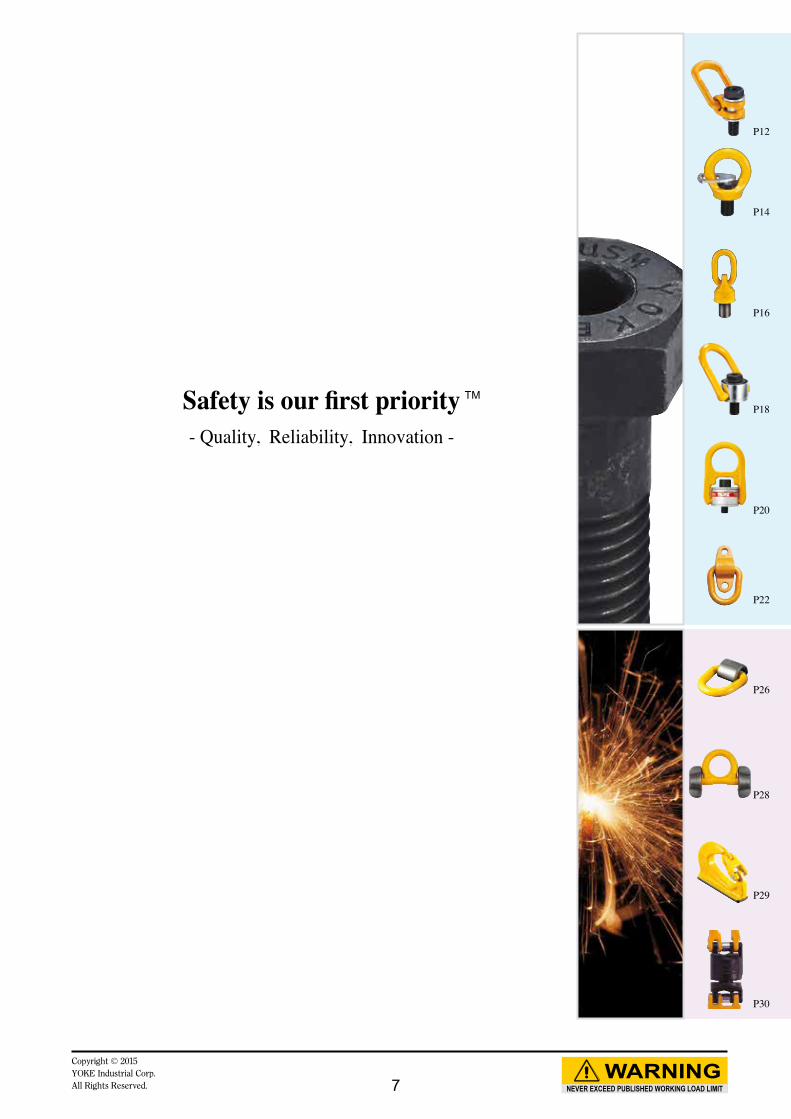
Safety is our first priority- Quality, Reliability, Innovation -
TM
7
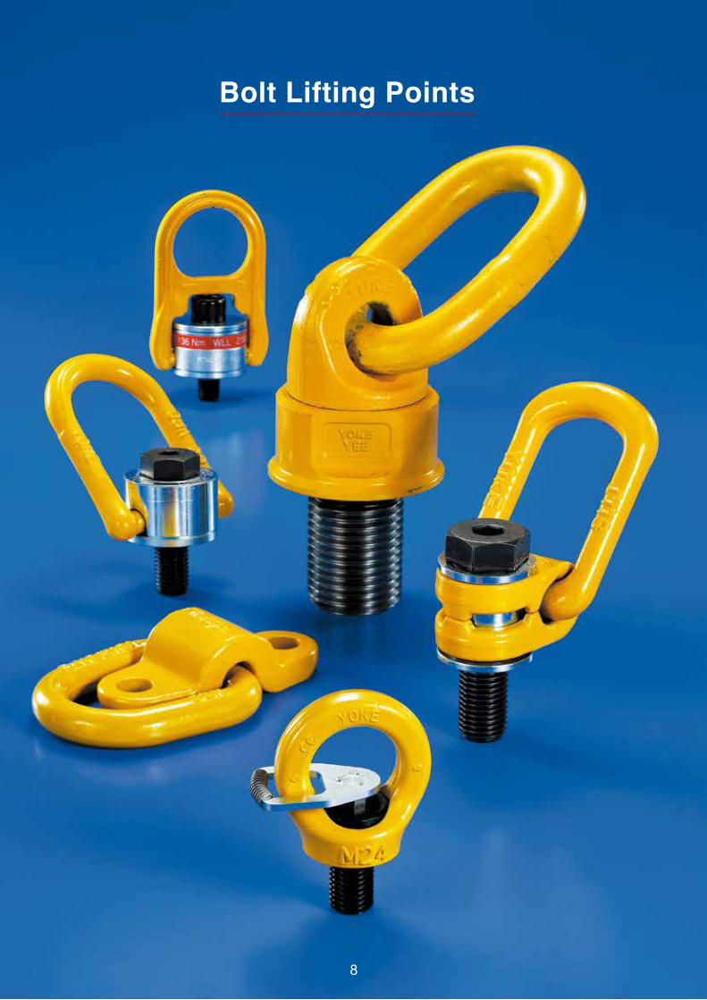
Bolt Lifting Points
8
NEVER EXCEED PUBLISHED WORKING LOAD LIMITWARNING
Copyright © 2015YOKE Industrial Corp.All Rights Reserved.
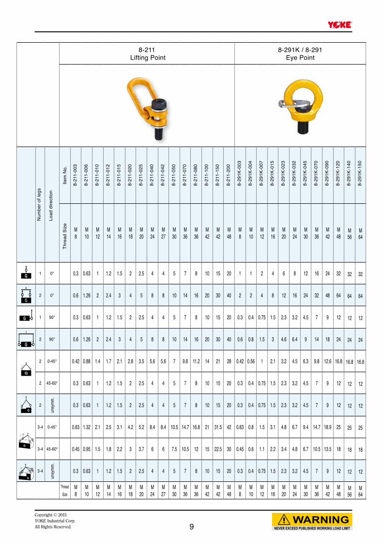
8-211 Lifting Point
8-291K / 8-291Eye Point
Num
ber o
f leg
s
Load
dire
ctio
n
Item
No.
Thre
ad S
ize
M 8
M 10
M 12
M 14
M 16
M 18
M 20
M 24
M 27
M 30
M 36
M 36
M 42
M 42
M 48
M 8
M 10
M 12
M 16
M 20
M 24
M 30
M 36
M 42
M 48
M56
M64
1 0° 0.3 0.63 1 1.2 1.5 2 2.5 4 4 5 7 8 10 15 20 1 1 2 4 6 8 12 16 24 32 32 32
2 0° 0.6 1.26 2 2.4 3 4 5 8 8 10 14 16 20 30 40 2 2 4 8 12 16 24 32 48 64 64 64
1 90° 0.3 0.63 1 1.2 1.5 2 2.5 4 4 5 7 8 10 15 20 0.3 0.4 0.75 1.5 2.3 3.2 4.5 7 9 12 12 12
2 90° 0.6 1.26 2 2.4 3 4 5 8 8 10 14 16 20 30 40 0.6 0.8 1.5 3 4.6 6.4 9 14 18 24 24 24
2 0-45° 0.42 0.88 1.4 1.7 2.1 2.8 3.5 5.6 5.6 7 9.8 11.2 14 21 28 0.42 0.56 1 2.1 3.2 4.5 6.3 9.8 12.6 16.8 16.8 16.8
2 45-60° 0.3 0.63 1 1.2 1.5 2 2.5 4 4 5 7 8 10 15 20 0.3 0.4 0.75 1.5 2.3 3.2 4.5 7 9 12 12 12
2
unsy
mm.
0.3 0.63 1 1.2 1.5 2 2.5 4 4 5 7 8 10 15 20 0.3 0.4 0.75 1.5 2.3 3.2 4.5 7 9 12 12 12
3-4 0-45° 0.63 1.32 2.1 2.5 3.1 4.2 5.2 8.4 8.4 10.5 14.7 16.8 21 31.5 42 0.63 0.8 1.5 3.1 4.8 6.7 9.4 14.7 18.9 25 25 25
3-4 45-60° 0.45 0.95 1.5 1.8 2.2 3 3.7 6 6 7.5 10.5 12 15 22.5 30 0.45 0.6 1.1 2.2 3.4 4.8 6.7 10.5 13.5 18 18 18
3-4
unsy
mm.
0.3 0.63 1 1.2 1.5 2 2.5 4 4 5 7 8 10 15 20 0.3 0.4 0.75 1.5 2.3 3.2 4.5 7 9 12 12 12
Thread Size
M 8
M 10
M 12
M 14
M 16
M 18
M 20
M 24
M 27
M 30
M 36
M 36
M 42
M 42
M 48
M 8
M 10
M 12
M 16
M 20
M 24
M 30
M 36
M 42
M 48
M56
M64
8-21
1-00
3
8-21
1-00
6
8-21
1-01
0
8-21
1-01
2
8-21
1-01
5
8-21
1-02
0
8-21
1-02
5
8-21
1-04
0
8-21
1-04
2
8-21
1-05
0
8-21
1-07
0
8-21
1-08
0
8-21
1-10
0
8-21
1-15
0
8-21
1-20
0
8-29
1K-0
03
8-29
1K-0
04
8-29
1K-0
07
8-29
1K-0
15
8-29
1K-0
23
8-29
1K-0
32
8-29
1K-0
45
8-29
1K-0
70
8-29
1K-0
90
8-29
1K-1
20
8-29
1K-1
40
8-29
1K-1
50
9
NEVER EXCEED PUBLISHED WORKING LOAD LIMITWARNING
Copyright © 2015YOKE Industrial Corp.
All Rights Reserved.
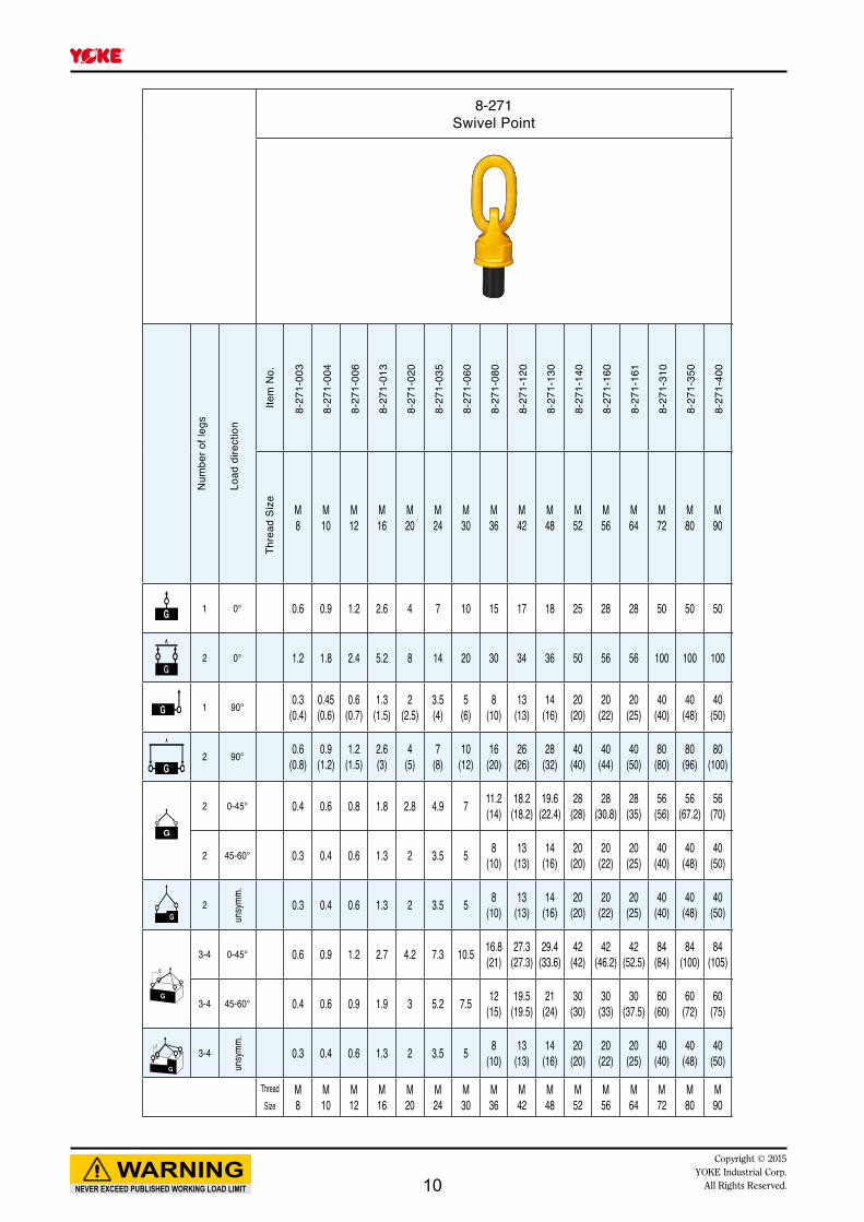
8-271Swivel Point
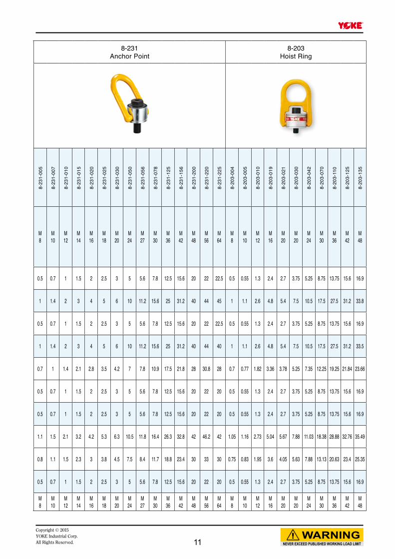
8-231Anchor Point
8-203Hoist Ring
Num
ber o
f leg
s
Load
dire
ctio
n
Item
No.
Thre
ad S
ize
M 8
M 10
M 12
M 16
M 20
M 24
M 30
M 36
M 42
M 48
M 52
M 56
M 64
M 72
M 80
M 90
M 8
M 10
M 12
M 14
M 16
M 18
M 20
M 24
M 27
M 30
M 36
M 42
M 48
M 56
M 64
M 8
M 10
M 12
M 16
M 20
M 20
M 24
M 30
M 36
M 42
M48
1 0° 0.6 0.9 1.2 2.6 4 7 10 15 17 18 25 28 28 50 50 50 0.5 0.7 1 1.5 2 2.5 3 5 5.6 7.8 12.5 15.6 20 22 22.5 0.5 0.55 1.3 2.4 2.7 3.75 5.25 8.75 13.75 15.6 16.9
2 0° 1.2 1.8 2.4 5.2 8 14 20 30 34 36 50 56 56 100 100 100 1 1.4 2 3 4 5 6 10 11.2 15.6 25 31.2 40 44 45 1 1.1 2.6 4.8 5.4 7.5 10.5 17.5 27.5 31.2 33.8
1 90° 0.3 (0.4)
0.45 (0.6)
0.6 (0.7)
1.3 (1.5)
2 (2.5)
3.5 (4)
5 (6)
8 (10)
13 (13)
14 (16)
20 (20)
20 (22)
20 (25)
40(40)
40 (48)
40 (50) 0.5 0.7 1 1.5 2 2.5 3 5 5.6 7.8 12.5 15.6 20 22 22.5 0.5 0.55 1.3 2.4 2.7 3.75 5.25 8.75 13.75 15.6 16.9
2 90° 0.6 (0.8)
0.9 (1.2)
1.2 (1.5)
2.6 (3)
4 (5)
7 (8)
10 (12)
16 (20)
26 (26)
28 (32)
40 (40)
40 (44)
40 (50)
80 (80)
80 (96)
80 (100) 1 1.4 2 3 4 5 6 10 11.2 15.6 25 31.2 40 44 40 1 1.1 2.6 4.8 5.4 7.5 10.5 17.5 27.5 31.2 33.5
2 0-45° 0.4 0.6 0.8 1.8 2.8 4.9 7 11.2 (14)
18.2(18.2)
19.6(22.4)
28 (28)
28 (30.8)
28 (35)
56 (56)
56 (67.2)
56 (70) 0.7 1 1.4 2.1 2.8 3.5 4.2 7 7.8 10.9 17.5 21.8 28 30.8 28 0.7 0.77 1.82 3.36 3.78 5.25 7.35 12.25 19.25 21.84 23.66
2 45-60° 0.3 0.4 0.6 1.3 2 3.5 5 8 (10)
13(13)
14 (16)
20 (20)
20 (22)
20 (25)
40 (40)
40 (48)
40 (50) 0.5 0.7 1 1.5 2 2.5 3 5 5.6 7.8 12.5 15.6 20 22 20 0.5 0.55 1.3 2.4 2.7 3.75 5.25 8.75 13.75 15.6 16.9
2
unsy
mm.
0.3 0.4 0.6 1.3 2 3.5 5 8 (10)
13 (13)
14 (16)
20 (20)
20 (22)
20 (25)
40 (40)
40 (48)
40 (50) 0.5 0.7 1 1.5 2 2.5 3 5 5.6 7.8 12.5 15.6 20 22 20 0.5 0.55 1.3 2.4 2.7 3.75 5.25 8.75 13.75 15.6 16.9
3-4 0-45° 0.6 0.9 1.2 2.7 4.2 7.3 10.5 16.8 (21)
27.3 (27.3)
29.4 (33.6)
42 (42)
42 (46.2)
42 (52.5)
84 (84)
84 (100)
84 (105) 1.1 1.5 2.1 3.2 4.2 5.3 6.3 10.5 11.8 16.4 26.3 32.8 42 46.2 42 1.05 1.16 2.73 5.04 5.67 7.88 11.03 18.38 28.88 32.76 35.49
3-4 45-60° 0.4 0.6 0.9 1.9 3 5.2 7.5 12 (15)
19.5 (19.5)
21 (24)
30 (30)
30 (33)
30 (37.5)
60 (60)
60 (72)
60 (75) 0.8 1.1 1.5 2.3 3 3.8 4.5 7.5 8.4 11.7 18.8 23.4 30 33 30 0.75 0.83 1.95 3.6 4.05 5.63 7.88 13.13 20.63 23.4 25.35
3-4
unsy
mm.
0.3 0.4 0.6 1.3 2 3.5 5 8 (10)
13 (13)
14 (16)
20 (20)
20 (22)
20 (25)
40 (40)
40 (48)
40 (50) 0.5 0.7 1 1.5 2 2.5 3 5 5.6 7.8 12.5 15.6 20 22 20 0.5 0.55 1.3 2.4 2.7 3.75 5.25 8.75 13.75 15.6 16.9
Thread Size
M 8
M 10
M 12
M 16
M 20
M 24
M 30
M 36
M 42
M 48
M 52
M 56
M 64
M 72
M 80
M 90
M 8
M 10
M 12
M 14
M 16
M 18
M 20
M 24
M 27
M 30
M 36
M 42
M 48
M 56
M 64
M 8
M 10
M 12
M 16
M 20
M 20
M 24
M 30
M 36
M 42
M 48
8-27
1-00
3
8-27
1-00
4
8-27
1-00
6
8-27
1-01
3
8-27
1-02
0
8-27
1-03
5
8-27
1-06
0
8-27
1-08
0
8-27
1-12
0
8-27
1-13
0
8-27
1-14
0
8-27
1-16
0
8-27
1-16
1
8-27
1-31
0
8-27
1-35
0
8-27
1-40
0
8-23
1-00
5
8-23
1-00
7
8-23
1-01
0
8-23
1-01
5
8-23
1-02
0
8-23
1-02
5
8-23
1-03
0
8-23
1-05
0
8-23
1-05
6
8-23
1-07
8
8-23
1-12
5
8-23
1-15
6
8-23
1-20
0
8-23
1-22
0
8-23
1-22
5
8-20
3-00
4
8-20
3-00
5
8-20
3-01
0
8-20
3-01
9
8-20
3-02
1
8-20
3-03
0
8-20
3-04
2
8-20
3-07
0
8-20
3-11
0
8-20
3-12
5
8-20
3-13
5
10
NEVER EXCEED PUBLISHED WORKING LOAD LIMITWARNING
Copyright © 2015YOKE Industrial Corp.All Rights Reserved.
8-271Swivel Point
8-231Anchor Point
8-203Hoist Ring
Num
ber o
f leg
s
Load
dire
ctio
n
Item
No.
Thre
ad S
ize
M 8
M 10
M 12
M 16
M 20
M 24
M 30
M 36
M 42
M 48
M 52
M 56
M 64
M 72
M 80
M 90
M 8
M 10
M 12
M 14
M 16
M 18
M 20
M 24
M 27
M 30
M 36
M 42
M 48
M 56
M 64
M 8
M 10
M 12
M 16
M 20
M 20
M 24
M 30
M 36
M 42
M48
1 0° 0.6 0.9 1.2 2.6 4 7 10 15 17 18 25 28 28 50 50 50 0.5 0.7 1 1.5 2 2.5 3 5 5.6 7.8 12.5 15.6 20 22 22.5 0.5 0.55 1.3 2.4 2.7 3.75 5.25 8.75 13.75 15.6 16.9
2 0° 1.2 1.8 2.4 5.2 8 14 20 30 34 36 50 56 56 100 100 100 1 1.4 2 3 4 5 6 10 11.2 15.6 25 31.2 40 44 45 1 1.1 2.6 4.8 5.4 7.5 10.5 17.5 27.5 31.2 33.8
1 90° 0.3 (0.4)
0.45 (0.6)
0.6 (0.7)
1.3 (1.5)
2 (2.5)
3.5 (4)
5 (6)
8 (10)
13 (13)
14 (16)
20 (20)
20 (22)
20 (25)
40(40)
40 (48)
40 (50) 0.5 0.7 1 1.5 2 2.5 3 5 5.6 7.8 12.5 15.6 20 22 22.5 0.5 0.55 1.3 2.4 2.7 3.75 5.25 8.75 13.75 15.6 16.9
2 90° 0.6 (0.8)
0.9 (1.2)
1.2 (1.5)
2.6 (3)
4 (5)
7 (8)
10 (12)
16 (20)
26 (26)
28 (32)
40 (40)
40 (44)
40 (50)
80 (80)
80 (96)
80 (100) 1 1.4 2 3 4 5 6 10 11.2 15.6 25 31.2 40 44 40 1 1.1 2.6 4.8 5.4 7.5 10.5 17.5 27.5 31.2 33.5
2 0-45° 0.4 0.6 0.8 1.8 2.8 4.9 7 11.2 (14)
18.2(18.2)
19.6(22.4)
28 (28)
28 (30.8)
28 (35)
56 (56)
56 (67.2)
56 (70) 0.7 1 1.4 2.1 2.8 3.5 4.2 7 7.8 10.9 17.5 21.8 28 30.8 28 0.7 0.77 1.82 3.36 3.78 5.25 7.35 12.25 19.25 21.84 23.66
2 45-60° 0.3 0.4 0.6 1.3 2 3.5 5 8 (10)
13(13)
14 (16)
20 (20)
20 (22)
20 (25)
40 (40)
40 (48)
40 (50) 0.5 0.7 1 1.5 2 2.5 3 5 5.6 7.8 12.5 15.6 20 22 20 0.5 0.55 1.3 2.4 2.7 3.75 5.25 8.75 13.75 15.6 16.9
2
unsy
mm.
0.3 0.4 0.6 1.3 2 3.5 5 8 (10)
13 (13)
14 (16)
20 (20)
20 (22)
20 (25)
40 (40)
40 (48)
40 (50) 0.5 0.7 1 1.5 2 2.5 3 5 5.6 7.8 12.5 15.6 20 22 20 0.5 0.55 1.3 2.4 2.7 3.75 5.25 8.75 13.75 15.6 16.9
3-4 0-45° 0.6 0.9 1.2 2.7 4.2 7.3 10.5 16.8 (21)
27.3 (27.3)
29.4 (33.6)
42 (42)
42 (46.2)
42 (52.5)
84 (84)
84 (100)
84 (105) 1.1 1.5 2.1 3.2 4.2 5.3 6.3 10.5 11.8 16.4 26.3 32.8 42 46.2 42 1.05 1.16 2.73 5.04 5.67 7.88 11.03 18.38 28.88 32.76 35.49
3-4 45-60° 0.4 0.6 0.9 1.9 3 5.2 7.5 12 (15)
19.5 (19.5)
21 (24)
30 (30)
30 (33)
30 (37.5)
60 (60)
60 (72)
60 (75) 0.8 1.1 1.5 2.3 3 3.8 4.5 7.5 8.4 11.7 18.8 23.4 30 33 30 0.75 0.83 1.95 3.6 4.05 5.63 7.88 13.13 20.63 23.4 25.35
3-4
unsy
mm.
0.3 0.4 0.6 1.3 2 3.5 5 8 (10)
13 (13)
14 (16)
20 (20)
20 (22)
20 (25)
40 (40)
40 (48)
40 (50) 0.5 0.7 1 1.5 2 2.5 3 5 5.6 7.8 12.5 15.6 20 22 20 0.5 0.55 1.3 2.4 2.7 3.75 5.25 8.75 13.75 15.6 16.9
Thread Size
M 8
M 10
M 12
M 16
M 20
M 24
M 30
M 36
M 42
M 48
M 52
M 56
M 64
M 72
M 80
M 90
M 8
M 10
M 12
M 14
M 16
M 18
M 20
M 24
M 27
M 30
M 36
M 42
M 48
M 56
M 64
M 8
M 10
M 12
M 16
M 20
M 20
M 24
M 30
M 36
M 42
M 48
8-27
1-00
3
8-27
1-00
4
8-27
1-00
6
8-27
1-01
3
8-27
1-02
0
8-27
1-03
5
8-27
1-06
0
8-27
1-08
0
8-27
1-12
0
8-27
1-13
0
8-27
1-14
0
8-27
1-16
0
8-27
1-16
1
8-27
1-31
0
8-27
1-35
0
8-27
1-40
0
8-23
1-00
5
8-23
1-00
7
8-23
1-01
0
8-23
1-01
5
8-23
1-02
0
8-23
1-02
5
8-23
1-03
0
8-23
1-05
0
8-23
1-05
6
8-23
1-07
8
8-23
1-12
5
8-23
1-15
6
8-23
1-20
0
8-23
1-22
0
8-23
1-22
5
8-20
3-00
4
8-20
3-00
5
8-20
3-01
0
8-20
3-01
9
8-20
3-02
1
8-20
3-03
0
8-20
3-04
2
8-20
3-07
0
8-20
3-11
0
8-20
3-12
5
8-20
3-13
5
11
E
M
H C
F
A
D
G
B
SSW
NEVER EXCEED PUBLISHED WORKING LOAD LIMITWARNING
Copyright © 2015YOKE Industrial Corp.
All Rights Reserved.
Repair Kits
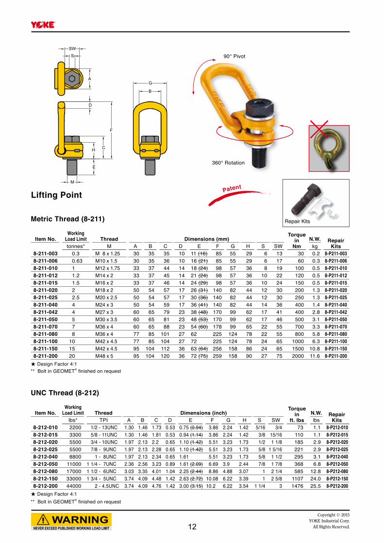
Lifting Point
360° Rotation
90° Pivot
Metric Thread (8-211)
Item No.Working
Load Limit Thread Dimensions (mm)Torque
inNm
N.W. Repair Kitstonnes* M A B C D E F G H S SW kg
8-211-003 0.3 M 8 x 1.25 30 35 35 10 11 (16) 85 55 29 6 13 30 0.2 8-P211-0038-211-006 0.63 M10 x 1.5 30 35 36 10 16 (21) 85 55 29 6 17 60 0.3 8-P211-0068-211-010 1 M12 x 1.75 33 37 44 14 18 (24) 98 57 36 8 19 100 0.5 8-P211-0108-211-012 1.2 M14 x 2 33 37 45 14 21 (24) 98 57 36 10 22 120 0.5 8-P211-0128-211-015 1.5 M16 x 2 33 37 46 14 24 (29) 98 57 36 10 24 150 0.5 8-P211-0158-211-020 2 M18 x 2 50 54 57 17 26 (31) 140 82 44 12 30 200 1.3 8-P211-0208-211-025 2.5 M20 x 2.5 50 54 57 17 30 (36) 140 82 44 12 30 250 1.3 8-P211-0258-211-040 4 M24 x 3 50 54 59 17 36 (41) 140 82 44 14 36 400 1.4 8-P211-0408-211-042 4 M27 x 3 60 65 79 23 38 (48) 170 99 62 17 41 400 2.8 8-P211-0428-211-050 5 M30 x 3.5 60 65 81 23 48 (53) 170 99 62 17 46 500 3.1 8-P211-0508-211-070 7 M36 x 4 60 65 88 23 54 (60) 178 99 65 22 55 700 3.3 8-P211-0708-211-080 8 M36 x 4 77 85 101 27 62 225 124 78 22 55 800 5.8 8-P211-0808-211-100 10 M42 x 4.5 77 85 104 27 72 225 124 78 24 65 1000 6.3 8-P211-1008-211-150 15 M42 x 4.5 95 104 112 36 63 (64) 256 158 86 24 65 1500 10.8 8-P211-1508-211-200 20 M48 x 5 95 104 120 36 72 (75) 259 158 90 27 75 2000 11.6 8-P211-200
★ Design Factor 4:1** Bolt in GEOMET® finished on request
UNC Thread (8-212)
Item No.Working
Load Limit Thread Dimensions (inch)Torque
inft. lbs
N.W. Repair Kitslbs* TPI A B C D E F G H S SW lbs
8-212-010 2200 1/2 - 13UNC 1.30 1.46 1.73 0.53 0.75 (0.94) 3.86 2.24 1.42 5/16 3/4 73 1.1 8-P212-0108-212-015 3300 5/8 - 11UNC 1.30 1.46 1.81 0.53 0.94 (1.14) 3.86 2.24 1.42 3/8 15/16 110 1.1 8-P212-0158-212-020 5500 3/4 - 10UNC 1.97 2.13 2.2 0.65 1.10 (1.42) 5.51 3.23 1.73 1/2 1 1/8 185 2.9 8-P212-0208-212-025 5500 7/8 - 9UNC 1.97 2.13 2.28 0.65 1.10 (1.42) 5.51 3.23 1.73 5/8 1 5/16 221 2.9 8-P212-0258-212-040 8800 1 - 8UNC 1.97 2.13 2.34 0.65 1.61 5.51 3.23 1.73 5/8 1 1/2 295 3.1 8-P212-0408-212-050 11000 1 1/4 - 7UNC 2.36 2.56 3.23 0.89 1.61 (2.09) 6.69 3.9 2.44 7/8 1 7/8 368 6.8 8-P212-0508-212-080 17000 1 1/2 - 6UNC 3.03 3.35 4.01 1.04 2.25 (2.44) 8.86 4.88 3.07 1 2 1/4 585 12.8 8-P212-0808-212-150 33000 1 3/4 - 5UNC 3.74 4.09 4.48 1.42 2.63 (2.72) 10.08 6.22 3.39 1 2 5/8 1107 24.0 8-P212-1508-212-200 44000 2 - 4.5UNC 3.74 4.09 4.76 1.42 3.00 (3.15) 10.2 6.22 3.54 1 1/4 3 1476 25.5 8-P212-200
★ Design Factor 4:1** Bolt in GEOMET® finished on request
Patent
12
MM
EE
HH
DD
CC
FF
AA
SSSWSW
GGBB 90° Pivot
NEVER EXCEED PUBLISHED WORKING LOAD LIMITWARNING
Copyright © 2015YOKE Industrial Corp.All Rights Reserved.
Repair Kits
360° Rotation
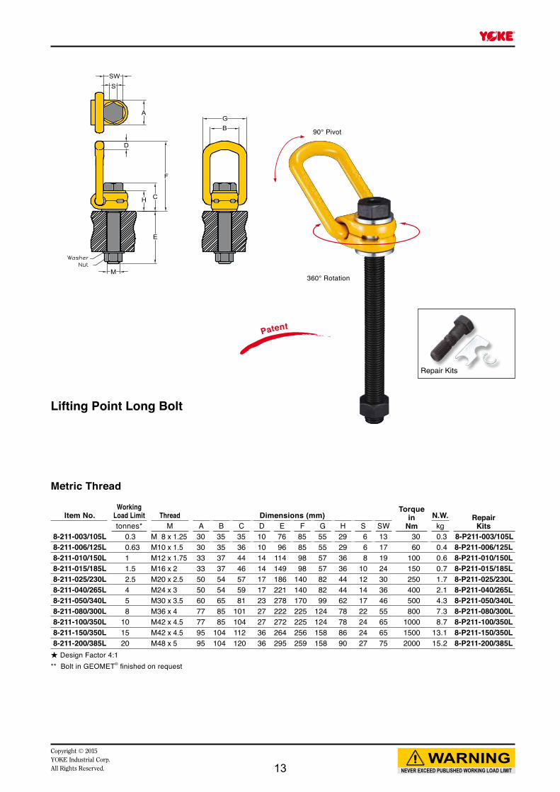
Lifting Point Long Bolt
Metric Thread
Item No.Working
Load Limit Thread Dimensions (mm)Torque
inNm
N.W. RepairKitstonnes* M A B C D E F G H S SW kg
8-211-003/105L 0.3 M 8 x 1.25 30 35 35 10 76 85 55 29 6 13 30 0.3 8-P211-003/105L8-211-006/125L 0.63 M10 x 1.5 30 35 36 10 96 85 55 29 6 17 60 0.4 8-P211-006/125L8-211-010/150L 1 M12 x 1.75 33 37 44 14 114 98 57 36 8 19 100 0.6 8-P211-010/150L8-211-015/185L 1.5 M16 x 2 33 37 46 14 149 98 57 36 10 24 150 0.7 8-P211-015/185L8-211-025/230L 2.5 M20 x 2.5 50 54 57 17 186 140 82 44 12 30 250 1.7 8-P211-025/230L8-211-040/265L 4 M24 x 3 50 54 59 17 221 140 82 44 14 36 400 2.1 8-P211-040/265L8-211-050/340L 5 M30 x 3.5 60 65 81 23 278 170 99 62 17 46 500 4.3 8-P211-050/340L8-211-080/300L 8 M36 x 4 77 85 101 27 222 225 124 78 22 55 800 7.3 8-P211-080/300L8-211-100/350L 10 M42 x 4.5 77 85 104 27 272 225 124 78 24 65 1000 8.7 8-P211-100/350L8-211-150/350L 15 M42 x 4.5 95 104 112 36 264 256 158 86 24 65 1500 13.1 8-P211-150/350L8-211-200/385L 20 M48 x 5 95 104 120 36 295 259 158 90 27 75 2000 15.2 8-P211-200/385L
★ Design Factor 4:1** Bolt in GEOMET® finished on request
Patent
13
NEVER EXCEED PUBLISHED WORKING LOAD LIMITWARNING
Copyright © 2015YOKE Industrial Corp.
All Rights Reserved.
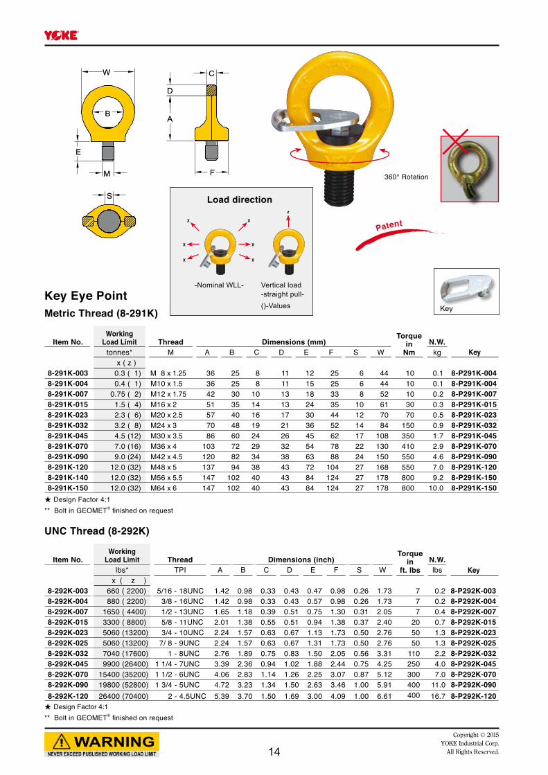
Key
360° Rotation
Key Eye Point
CC
DD
AA
FF
EE
MM
BB
WW
SS
PatentX
X
X
X
X
X
Load direction
-Nominal WLL- Vertical load-straight pull-()-Values
z
Metric Thread (8-291K)
Item No.Working
Load Limit Thread Dimensions (mm)Torque
in Nm
N.W.tonnes* M A B C D E F S W kg Key
x ( z )8-291K-003 0.3 ( 1) M 8 x 1.25 36 25 8 11 12 25 6 44 10 0.1 8-P291K-0048-291K-004 0.4 ( 1) M10 x 1.5 36 25 8 11 15 25 6 44 10 0.1 8-P291K-0048-291K-007 0.75 ( 2) M12 x 1.75 42 30 10 13 18 33 8 52 10 0.2 8-P291K-0078-291K-015 1.5 ( 4) M16 x 2 51 35 14 13 24 35 10 61 30 0.3 8-P291K-0158-291K-023 2.3 ( 6) M20 x 2.5 57 40 16 17 30 44 12 70 70 0.5 8-P291K-0238-291K-032 3.2 ( 8) M24 x 3 70 48 19 21 36 52 14 84 150 0.9 8-P291K-0328-291K-045 4.5 (12) M30 x 3.5 86 60 24 26 45 62 17 108 350 1.7 8-P291K-0458-291K-070 7.0 (16) M36 x 4 103 72 29 32 54 78 22 130 410 2.9 8-P291K-0708-291K-090 9.0 (24) M42 x 4.5 120 82 34 38 63 88 24 150 550 4.6 8-P291K-0908-291K-120 12.0 (32) M48 x 5 137 94 38 43 72 104 27 168 550 7.0 8-P291K-1208-291K-140 12.0 (32) M56 x 5.5 147 102 40 43 84 124 27 178 800 9.2 8-P291K-1508-291K-150 12.0 (32) M64 x 6 147 102 40 43 84 124 27 178 800 10.0 8-P291K-150
★ Design Factor 4:1** Bolt in GEOMET® finished on request
UNC Thread (8-292K)
Item No.Working
Load Limit Thread Dimensions (inch)Torque
inft. lbs
N.W.Keylbs* TPI A B C D E F S W lbs
x ( z )8-292K-003 660 ( 2200) 5/16 - 18UNC 1.42 0.98 0.33 0.43 0.47 0.98 0.26 1.73 7 0.2 8-P292K-0038-292K-004 880 ( 2200) 3/8 - 16UNC 1.42 0.98 0.33 0.43 0.57 0.98 0.26 1.73 7 0.2 8-P292K-0048-292K-007 1650 ( 4400) 1/2 - 13UNC 1.65 1.18 0.39 0.51 0.75 1.30 0.31 2.05 7 0.4 8-P292K-0078-292K-015 3300 ( 8800) 5/8 - 11UNC 2.01 1.38 0.55 0.51 0.94 1.38 0.37 2.40 20 0.7 8-P292K-0158-292K-023 5060 (13200) 3/4 - 10UNC 2.24 1.57 0.63 0.67 1.13 1.73 0.50 2.76 50 1.3 8-P292K-0238-292K-025 5060 (13200) 7/ 8 - 9UNC 2.24 1.57 0.63 0.67 1.31 1.73 0.50 2.76 50 1.3 8-P292K-0258-292K-032 7040 (17600) 1 - 8UNC 2.76 1.89 0.75 0.83 1.50 2.05 0.56 3.31 110 2.2 8-P292K-0328-292K-045 9900 (26400) 1 1/4 - 7UNC 3.39 2.36 0.94 1.02 1.88 2.44 0.75 4.25 250 4.0 8-P292K-0458-292K-070 15400 (35200) 1 1/2 - 6UNC 4.06 2.83 1.14 1.26 2.25 3.07 0.87 5.12 300 7.0 8-P292K-0708-292K-090 19800 (52800) 1 3/4 - 5UNC 4.72 3.23 1.34 1.50 2.63 3.46 1.00 5.91 400 11.0 8-P292K-0908-292K-120 26400 (70400) 2 - 4.5UNC 5.39 3.70 1.50 1.69 3.00 4.09 1.00 6.61 400 16.7 8-P292K-120
★ Design Factor 4:1** Bolt in GEOMET® finished on request
14
NEVER EXCEED PUBLISHED WORKING LOAD LIMITWARNING
Copyright © 2015YOKE Industrial Corp.All Rights Reserved.
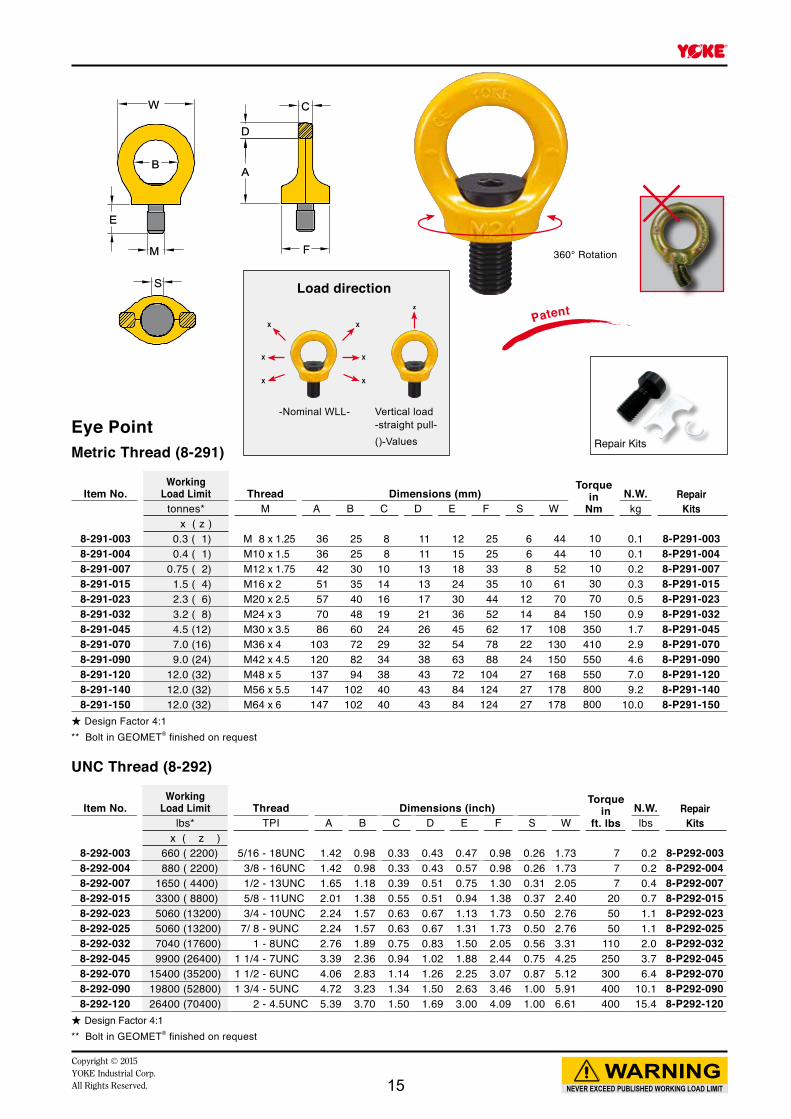
360° Rotation
Patent
Eye Point
CC
DD
AA
FF
EE
MM
BB
WW
SS
Repair Kits
Load direction
-Nominal WLL- Vertical load-straight pull-()-Values
z
Metric Thread (8-291)
Item No.Working
Load Limit Thread Dimensions (mm)Torque
in Nm
N.W. RepairKitstonnes* M A B C D E F S W kg
x ( z )8-291-003 0.3 ( 1) M 8 x 1.25 36 25 8 11 12 25 6 44 10 0.1 8-P291-0038-291-004 0.4 ( 1) M10 x 1.5 36 25 8 11 15 25 6 44 10 0.1 8-P291-0048-291-007 0.75 ( 2) M12 x 1.75 42 30 10 13 18 33 8 52 10 0.2 8-P291-0078-291-015 1.5 ( 4) M16 x 2 51 35 14 13 24 35 10 61 30 0.3 8-P291-0158-291-023 2.3 ( 6) M20 x 2.5 57 40 16 17 30 44 12 70 70 0.5 8-P291-0238-291-032 3.2 ( 8) M24 x 3 70 48 19 21 36 52 14 84 150 0.9 8-P291-0328-291-045 4.5 (12) M30 x 3.5 86 60 24 26 45 62 17 108 350 1.7 8-P291-0458-291-070 7.0 (16) M36 x 4 103 72 29 32 54 78 22 130 410 2.9 8-P291-0708-291-090 9.0 (24) M42 x 4.5 120 82 34 38 63 88 24 150 550 4.6 8-P291-0908-291-120 12.0 (32) M48 x 5 137 94 38 43 72 104 27 168 550 7.0 8-P291-1208-291-140 12.0 (32) M56 x 5.5 147 102 40 43 84 124 27 178 800 9.2 8-P291-1408-291-150 12.0 (32) M64 x 6 147 102 40 43 84 124 27 178 800 10.0 8-P291-150
★ Design Factor 4:1** Bolt in GEOMET® finished on request
UNC Thread (8-292)
Item No.Working
Load Limit Thread Dimensions (inch)Torque
inft. lbs
N.W. RepairKitslbs* TPI A B C D E F S W lbs
x ( z )8-292-003 660 ( 2200) 5/16 - 18UNC 1.42 0.98 0.33 0.43 0.47 0.98 0.26 1.73 7 0.2 8-P292-0038-292-004 880 ( 2200) 3/8 - 16UNC 1.42 0.98 0.33 0.43 0.57 0.98 0.26 1.73 7 0.2 8-P292-0048-292-007 1650 ( 4400) 1/2 - 13UNC 1.65 1.18 0.39 0.51 0.75 1.30 0.31 2.05 7 0.4 8-P292-0078-292-015 3300 ( 8800) 5/8 - 11UNC 2.01 1.38 0.55 0.51 0.94 1.38 0.37 2.40 20 0.7 8-P292-0158-292-023 5060 (13200) 3/4 - 10UNC 2.24 1.57 0.63 0.67 1.13 1.73 0.50 2.76 50 1.1 8-P292-0238-292-025 5060 (13200) 7/ 8 - 9UNC 2.24 1.57 0.63 0.67 1.31 1.73 0.50 2.76 50 1.1 8-P292-0258-292-032 7040 (17600) 1 - 8UNC 2.76 1.89 0.75 0.83 1.50 2.05 0.56 3.31 110 2.0 8-P292-0328-292-045 9900 (26400) 1 1/4 - 7UNC 3.39 2.36 0.94 1.02 1.88 2.44 0.75 4.25 250 3.7 8-P292-0458-292-070 15400 (35200) 1 1/2 - 6UNC 4.06 2.83 1.14 1.26 2.25 3.07 0.87 5.12 300 6.4 8-P292-0708-292-090 19800 (52800) 1 3/4 - 5UNC 4.72 3.23 1.34 1.50 2.63 3.46 1.00 5.91 400 10.1 8-P292-0908-292-120 26400 (70400) 2 - 4.5UNC 5.39 3.70 1.50 1.69 3.00 4.09 1.00 6.61 400 15.4 8-P292-120
★ Design Factor 4:1** Bolt in GEOMET® finished on request
15
E
M K
CC
BB
AADD
FF
G
NEVER EXCEED PUBLISHED WORKING LOAD LIMITWARNING
Copyright © 2015YOKE Industrial Corp.
All Rights Reserved.
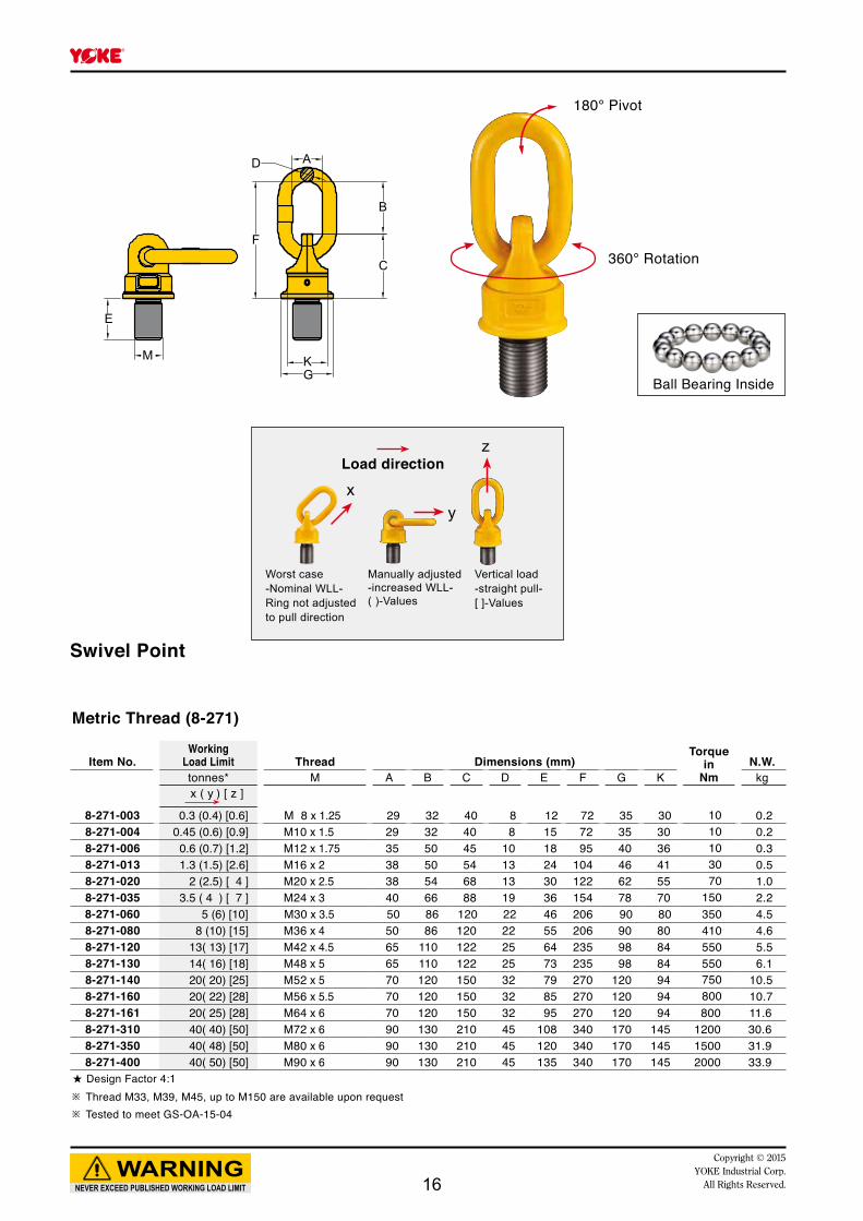
Metric Thread (8-271)
Item No.Working
Load Limit Thread Dimensions (mm)Torque
in Nm
N.W.tonnes* M A B C D E F G K kg
x ( y ) [ z ]
8-271-003 0.3 (0.4) [0.6] M 8 x 1.25 29 32 40 8 12 72 35 30 10 0.28-271-004 0.45 (0.6) [0.9] M10 x 1.5 29 32 40 8 15 72 35 30 10 0.28-271-006 0.6 (0.7) [1.2] M12 x 1.75 35 50 45 10 18 95 40 36 10 0.38-271-013 1.3 (1.5) [2.6] M16 x 2 38 50 54 13 24 104 46 41 30 0.58-271-020 2 (2.5) [ 4 ] M20 x 2.5 38 54 68 13 30 122 62 55 70 1.08-271-035 3.5 ( 4 ) [ 7 ] M24 x 3 40 66 88 19 36 154 78 70 150 2.28-271-060 5 (6) [10] M30 x 3.5 50 86 120 22 46 206 90 80 350 4.58-271-080 8 (10) [15] M36 x 4 50 86 120 22 55 206 90 80 410 4.68-271-120 13( 13) [17] M42 x 4.5 65 110 122 25 64 235 98 84 550 5.58-271-130 14( 16) [18] M48 x 5 65 110 122 25 73 235 98 84 550 6.18-271-140 20( 20) [25] M52 x 5 70 120 150 32 79 270 120 94 750 10.58-271-160 20( 22) [28] M56 x 5.5 70 120 150 32 85 270 120 94 800 10.78-271-161 20( 25) [28] M64 x 6 70 120 150 32 95 270 120 94 800 11.68-271-310 40( 40) [50] M72 x 6 90 130 210 45 108 340 170 145 1200 30.68-271-350 40( 48) [50] M80 x 6 90 130 210 45 120 340 170 145 1500 31.98-271-400 40( 50) [50] M90 x 6 90 130 210 45 135 340 170 145 2000 33.9
★ Design Factor 4:1※ Thread M33, M39, M45, up to M150 are available upon request※ Tested to meet GS-OA-15-04
Swivel Point
xy
zLoad direction
Worst case -Nominal WLL-Ring not adjusted to pull direction
Manually adjusted-increased WLL-( )-Values
Vertical load-straight pull-[ ]-Values
180° Pivot
360° Rotation
Ball Bearing Inside
16
E
M K
CC
BB
AADD
FF
G
NEVER EXCEED PUBLISHED WORKING LOAD LIMITWARNING
Copyright © 2015YOKE Industrial Corp.All Rights Reserved.
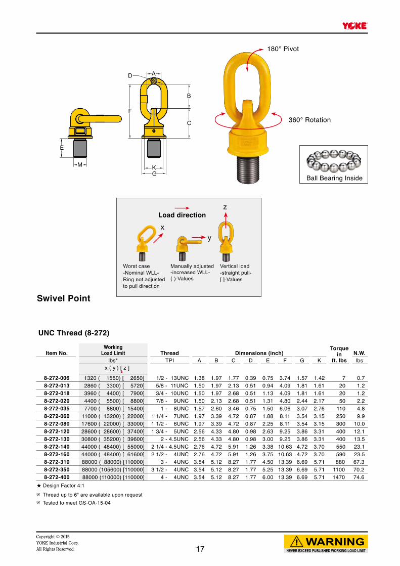
UNC Thread (8-272)
Item No.Working
Load Limit Thread Dimensions (inch)Torque
inft. lbs
N.W.lbs* TPI A B C D E F G K lbs
x ( y ) [ z ]
8-272-006 1320 ( 1550) [ 2650] 1/2 - 13UNC 1.38 1.97 1.77 0.39 0.75 3.74 1.57 1.42 7 0.78-272-013 2860 ( 3300) [ 5720] 5/8 - 11UNC 1.50 1.97 2.13 0.51 0.94 4.09 1.81 1.61 20 1.28-272-018 3960 ( 4400) [ 7900] 3/4 - 10UNC 1.50 1.97 2.68 0.51 1.13 4.09 1.81 1.61 20 1.28-272-020 4400 ( 5500) [ 8800] 7/8 - 9UNC 1.50 2.13 2.68 0.51 1.31 4.80 2.44 2.17 50 2.28-272-035 7700 ( 8800) [ 15400] 1 - 8UNC 1.57 2.60 3.46 0.75 1.50 6.06 3.07 2.76 110 4.88-272-060 11000 ( 13200) [ 22000] 1 1/4 - 7UNC 1.97 3.39 4.72 0.87 1.88 8.11 3.54 3.15 250 9.98-272-080 17600 ( 22000) [ 33000] 1 1/2 - 6UNC 1.97 3.39 4.72 0.87 2.25 8.11 3.54 3.15 300 10.08-272-120 28600 ( 28600) [ 37400] 1 3/4 - 5UNC 2.56 4.33 4.80 0.98 2.63 9.25 3.86 3.31 400 12.18-272-130 30800 ( 35200) [ 39600] 2 - 4.5UNC 2.56 4.33 4.80 0.98 3.00 9.25 3.86 3.31 400 13.58-272-140 44000 ( 48400) [ 55000] 2 1/4 - 4.5UNC 2.76 4.72 5.91 1.26 3.38 10.63 4.72 3.70 550 23.18-272-160 44000 ( 48400) [ 61600] 2 1/2 - 4UNC 2.76 4.72 5.91 1.26 3.75 10.63 4.72 3.70 590 23.58-272-310 88000 ( 88000) [110000] 3 - 4UNC 3.54 5.12 8.27 1.77 4.50 13.39 6.69 5.71 880 67.38-272-350 88000 (105600) [110000] 3 1/2 - 4UNC 3.54 5.12 8.27 1.77 5.25 13.39 6.69 5.71 1100 70.28-272-400 88000 (110000) [110000] 4 - 4UNC 3.54 5.12 8.27 1.77 6.00 13.39 6.69 5.71 1470 74.6
★ Design Factor 4:1※ Thread up to 6" are available upon request※ Tested to meet GS-OA-15-04
Swivel Point
xy
zLoad direction
Worst case -Nominal WLL-Ring not adjusted to pull direction
Manually adjusted-increased WLL-( )-Values
Vertical load-straight pull-[ ]-Values
180° Pivot
360° Rotation
Ball Bearing Inside
17
NEVER EXCEED PUBLISHED WORKING LOAD LIMITWARNING
Copyright © 2015YOKE Industrial Corp.
All Rights Reserved.
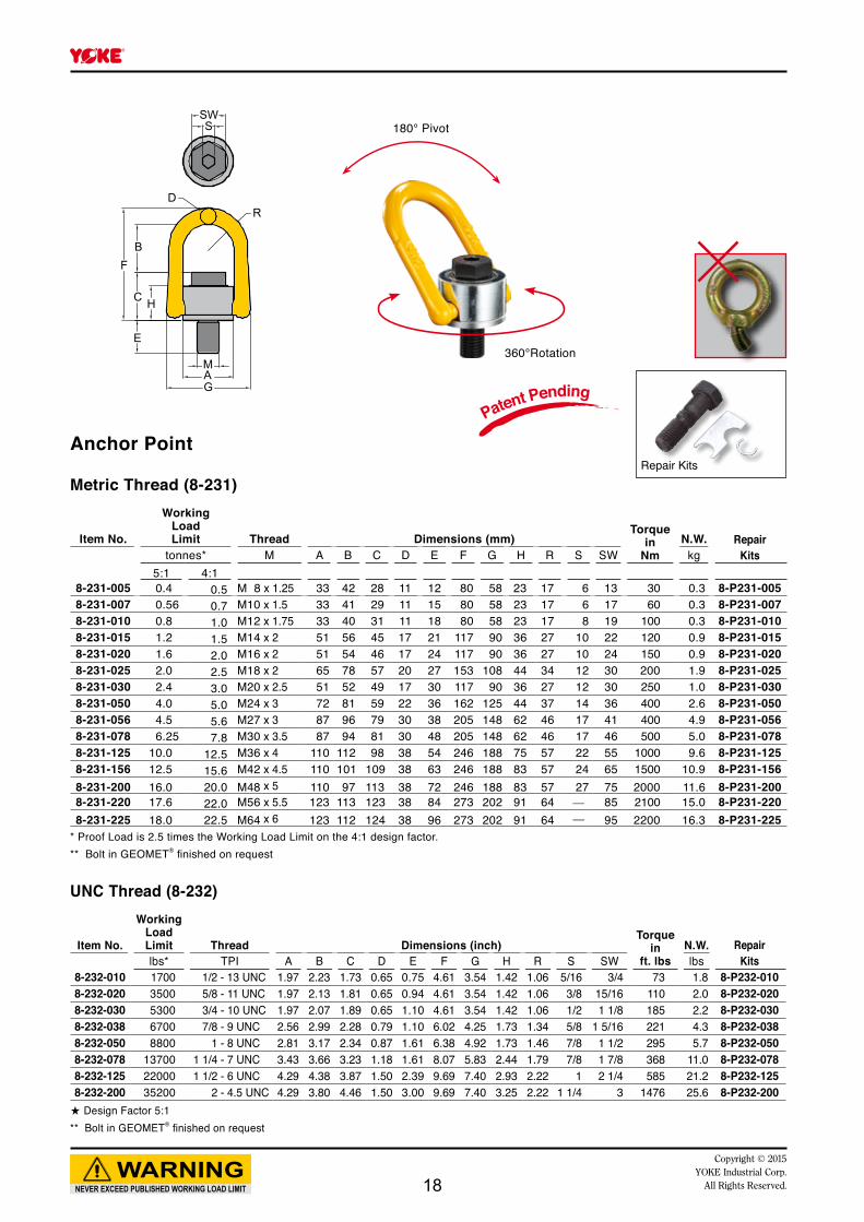
Anchor Point
UNC Thread (8-232)
Item No.
Working Load Limit Thread Dimensions (inch)
Torquein
ft. lbsN.W. Repair
Kitslbs* TPI A B C D E F G H R S SW lbs8-232-010 1700 1/2 - 13 UNC 1.97 2.23 1.73 0.65 0.75 4.61 3.54 1.42 1.06 5/16 3/4 73 1.8 8-P232-0108-232-020 3500 5/8 - 11 UNC 1.97 2.13 1.81 0.65 0.94 4.61 3.54 1.42 1.06 3/8 15/16 110 2.0 8-P232-0208-232-030 5300 3/4 - 10 UNC 1.97 2.07 1.89 0.65 1.10 4.61 3.54 1.42 1.06 1/2 1 1/8 185 2.2 8-P232-0308-232-038 6700 7/8 - 9 UNC 2.56 2.99 2.28 0.79 1.10 6.02 4.25 1.73 1.34 5/8 1 5/16 221 4.3 8-P232-0388-232-050 8800 1 - 8 UNC 2.81 3.17 2.34 0.87 1.61 6.38 4.92 1.73 1.46 7/8 1 1/2 295 5.7 8-P232-0508-232-078 13700 1 1/4 - 7 UNC 3.43 3.66 3.23 1.18 1.61 8.07 5.83 2.44 1.79 7/8 1 7/8 368 11.0 8-P232-0788-232-125 22000 1 1/2 - 6 UNC 4.29 4.38 3.87 1.50 2.39 9.69 7.40 2.93 2.22 1 2 1/4 585 21.2 8-P232-1258-232-200 35200 2 - 4.5 UNC 4.29 3.80 4.46 1.50 3.00 9.69 7.40 3.25 2.22 1 1/4 3 1476 25.6 8-P232-200★ Design Factor 5:1** Bolt in GEOMET® finished on request
Metric Thread (8-231)
Item No.
Working LoadLimit Thread Dimensions (mm)
Torquein
NmN.W. Repair
Kitstonnes* M A B C D E F G H R S SW kg5:1 4:1
8-231-005 0.4 0.5 M 8 x 1.25 33 42 28 11 12 80 58 23 17 6 13 30 0.3 8-P231-0058-231-007 0.56 0.7 M10 x 1.5 33 41 29 11 15 80 58 23 17 6 17 60 0.3 8-P231-0078-231-010 0.8 1.0 M12 x 1.75 33 40 31 11 18 80 58 23 17 8 19 100 0.3 8-P231-0108-231-015 1.2 1.5 M14 x 2 51 56 45 17 21 117 90 36 27 10 22 120 0.9 8-P231-0158-231-020 1.6 2.0 M16 x 2 51 54 46 17 24 117 90 36 27 10 24 150 0.9 8-P231-0208-231-025 2.0 2.5 M18 x 2 65 78 57 20 27 153 108 44 34 12 30 200 1.9 8-P231-0258-231-030 2.4 3.0 M20 x 2.5 51 52 49 17 30 117 90 36 27 12 30 250 1.0 8-P231-0308-231-050 4.0 5.0 M24 x 3 72 81 59 22 36 162 125 44 37 14 36 400 2.6 8-P231-0508-231-056 4.5 5.6 M27 x 3 87 96 79 30 38 205 148 62 46 17 41 400 4.9 8-P231-0568-231-078 6.25 7.8 M30 x 3.5 87 94 81 30 48 205 148 62 46 17 46 500 5.0 8-P231-0788-231-125 10.0 12.5 M36 x 4 110 112 98 38 54 246 188 75 57 22 55 1000 9.6 8-P231-1258-231-156 12.5 15.6 M42 x 4.5 110 101 109 38 63 246 188 83 57 24 65 1500 10.9 8-P231-1568-231-200 16.0 20.0 M48 x 5 110 97 113 38 72 246 188 83 57 27 75 2000 11.6 8-P231-2008-231-220 17.6 22.0 M56 x 5.5 123 113 123 38 84 273 202 91 64 ─ 85 2100 15.0 8-P231-2208-231-225 18.0 22.5 M64 x 6 123 112 124 38 96 273 202 91 64 ─ 95 2200 16.3 8-P231-225
* Proof Load is 2.5 times the Working Load Limit on the 4:1 design factor.** Bolt in GEOMET® finished on request
RD
SSW
BF
C
E
H
MAG
180° Pivot
360°Rotation
Repair Kits
Patent Pending
18
NEVER EXCEED PUBLISHED WORKING LOAD LIMITWARNING
Copyright © 2015YOKE Industrial Corp.All Rights Reserved.
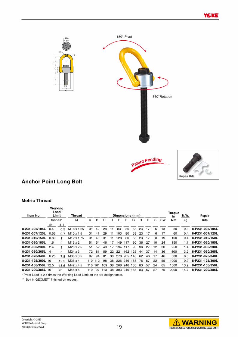
E
C
FB
RD
SSW
H
MAG
Repair Kits
180° Pivot
360°Rotation
Patent Pending
Anchor Point Long Bolt
Metric Thread
Item No.
Working LoadLimit Thread Dimensions (mm)
Torquein
NmN.W. Repair
Kitstonnes* M A B C D E F G H R S SW kg5:1 4:1
8-231-005/105L 0.4 0.5 M 8 x 1.25 31 42 28 11 83 80 58 23 17 6 13 30 0.3 8-P231-005/105L8-231-007/125L 0.56 0.7 M10 x 1.5 31 41 29 11 103 80 58 23 17 6 17 60 0.4 8-P231-007/125L8-231-010/150L 0.80 1 M12 x 1.75 31 40 31 11 128 80 58 23 17 8 19 100 0.4 8-P231-010/150L8-231-020/185L 1.6 2 M16 x 2 51 54 46 17 149 117 90 36 27 10 24 150 1.1 8-P231-020/185L8-231-030/230L 2.4 3 M20 x 2.5 51 52 49 17 194 117 90 36 27 12 30 250 1.4 8-P231-030/230L8-231-050/265L 4 5 M24 x 3 72 81 59 22 221 162 125 44 37 14 36 400 3.2 8-P231-050/265L8-231-078/340L 6.25 7.8 M30 x 3.5 87 94 81 30 278 205 148 62 46 17 46 500 6.3 8-P231-078/340L8-231-125/300L 10 12.5 M36 x 4 110 112 98 38 225 246 188 75 57 22 55 1000 10.9 8-P231-125/300L8-231-156/350L 12.5 15.6 M42 x 4.5 110 101 109 38 268 246 188 83 57 24 65 1500 13.9 8-P231-156/350L8-231-200/385L 16 20 M48 x 5 110 97 113 38 303 246 188 83 57 27 75 2000 14.7 8-P231-200/385L* Proof Load is 2.5 times the Working Load Limit on the 4:1 design factor.** Bolt in GEOMET® finished on request
19
F
E
MA
G
D
B
NEVER EXCEED PUBLISHED WORKING LOAD LIMITWARNING
Copyright © 2015YOKE Industrial Corp.
All Rights Reserved.
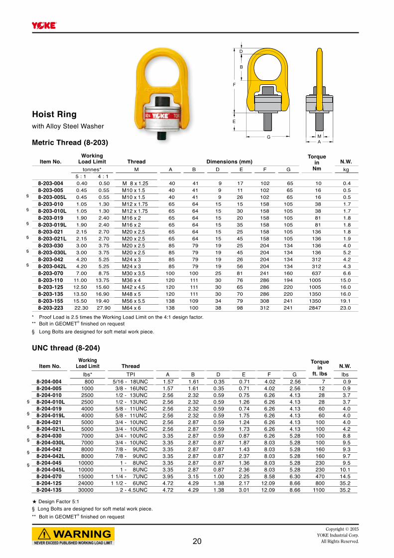
Item No.Working
Load Limit ThreadTorque
inft. lbs
N.W.lbs* TPI A B D E F G lbs
8-204-004 800 5/16 - 18UNC 1.57 1.61 0.35 0.71 4.02 2.56 7 0.98-204-005 1000 3/8 - 16UNC 1.57 1.61 0.35 0.71 4.02 2.56 12 0.98-204-010 2500 1/2 - 13UNC 2.56 2.32 0.59 0.75 6.26 4.13 28 3.78-204-010L 2500 1/2 - 13UNC 2.56 2.32 0.59 1.26 6.26 4.13 28 3.78-204-019 4000 5/8 - 11UNC 2.56 2.32 0.59 0.74 6.26 4.13 60 4.08-204-019L 4000 5/8 - 11UNC 2.56 2.32 0.59 1.75 6.26 4.13 60 4.08-204-021 5000 3/4 - 10UNC 2.56 2.87 0.59 1.24 6.26 4.13 100 4.08-204-021L 5000 3/4 - 10UNC 2.56 2.87 0.59 1.73 6.26 4.13 100 4.28-204-030 7000 3/4 - 10UNC 3.35 2.87 0.59 0.87 6.26 5.28 100 8.88-204-030L 7000 3/4 - 10UNC 3.35 2.87 0.87 1.87 8.03 5.28 100 9.58-204-042 8000 7/8 - 9UNC 3.35 2.87 0.87 1.43 8.03 5.28 160 9.38-204-042L 8000 7/8 - 9UNC 3.35 2.87 0.87 2.37 8.03 5.28 160 9.78-204-045 10000 1 - 8UNC 3.35 2.87 0.87 1.36 8.03 5.28 230 9.58-204-045L 10000 1 - 8UNC 3.35 2.87 0.87 2.36 8.03 5.28 230 10.18-204-070 15000 1 1/4 - 7UNC 3.95 3.15 1.00 2.25 8.58 6.30 470 14.58-204-125 24000 1 1/2 - 6UNC 4.72 4.29 1.38 2.17 12.09 8.66 800 35.28-204-135 30000 2 - 4.5UNC 4.72 4.29 1.38 3.01 12.09 8.66 1100 35.2
Hoist Ringwith Alloy Steel Washer
Metric Thread (8-203)
UNC thread (8-204)
§
§
§
§
§
§
★ Design Factor 5:1§ Long Bolts are designed for soft metal work piece. ** Bolt in GEOMET® finished on request
Item No.Working
Load Limit Thread Dimensions (mm)Torque
inNm
N.W.tonnes* M A B D E F G kg
5 : 1 4 : 18-203-004 0.40 0.50 M 8 x 1.25 40 41 9 17 102 65 10 0.48-203-005 0.45 0.55 M10 x 1.5 40 41 9 11 102 65 16 0.58-203-005L 0.45 0.55 M10 x 1.5 40 41 9 26 102 65 16 0.5 8-203-010 1.05 1.30 M12 x 1.75 65 64 15 15 158 105 38 1.78-203-010L 1.05 1.30 M12 x 1.75 65 64 15 30 158 105 38 1.78-203-019 1.90 2.40 M16 x 2 65 64 15 20 158 105 81 1.88-203-019L 1.90 2.40 M16 x 2 65 64 15 35 158 105 81 1.88-203-021 2.15 2.70 M20 x 2.5 65 64 15 25 158 105 136 1.88-203-021L 2.15 2.70 M20 x 2.5 65 64 15 45 158 105 136 1.98-203-030 3.00 3.75 M20 x 2.5 85 79 19 25 204 134 136 4.08-203-030L 3.00 3.75 M20 x 2.5 85 79 19 45 204 134 136 5.28-203-042 4.20 5.25 M24 x 3 85 79 19 26 204 134 312 4.28-203-042L 4.20 5.25 M24 x 3 85 79 19 56 204 134 312 4.38-203-070 7.00 8.75 M30 x 3.5 100 100 25 81 241 160 637 6.68-203-110 11.00 13.75 M36 x 4 120 111 30 76 286 194 1005 15.08-203-125 12.50 15.60 M42 x 4.5 120 111 30 65 286 220 1005 16.08-203-135 13.50 16.90 M48 x 5 120 111 30 70 286 220 1350 16.08-203-155 15.50 19.40 M56 x 5.5 138 109 34 79 308 241 1350 19.18-203-223 22.30 27.90 M64 x 6 138 100 38 98 312 241 2847 23.0
§
§
§
§
§
§
* Proof Load is 2.5 times the Working Load Limit on the 4:1 design factor.** Bolt in GEOMET® finished on request§ Long Bolts are designed for soft metal work piece.
20
F
E
MA
G
D
B
Item No.Working
Load Limit Thread Dimensions (mm)Torque
inNm
N.W.tonnes* M A B D E F G kg
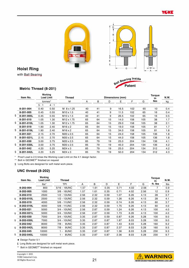
5 : 1 4 : 18-201-004 0.40 0.50 M 8 x 1.25 40 41 9 16.5 102 65 10 0.48-201-005 0.45 0.55 M10 x 1.5 40 41 9 11.5 102 65 16 0.48-201-005L 0.45 0.55 M10 x 1.5 40 41 9 26.5 102 65 16 0.5 8-201-010 1.05 1.30 M12 x 1.75 65 64 15 14.0 158 105 38 1.78-201-010L 1.05 1.30 M12 x 1.75 65 64 15 29.0 158 105 38 2.18-201-019 1.90 2.40 M16 x 2 65 64 15 19.0 158 105 81 1.78-201-019L 1.90 2.40 M16 x 2 65 64 15 34.0 158 105 81 1.88-201-021 2.15 2.70 M20 x 2.5 65 64 15 24.0 158 105 136 1.88-201-021L 2.15 2.70 M20 x 2.5 65 64 15 44.0 158 105 136 1.88-201-030 3.00 3.75 M20 x 2.5 85 79 19 25.0 204 134 136 4.18-201-030L 3.00 3.75 M20 x 2.5 85 79 19 45.0 204 134 136 4.28-201-042 4.20 5.25 M24 x 3 85 79 19 25.0 204 134 312 4.28-201-042L 4.20 5.25 M24 x 3 85 79 19 50.0 204 134 312 4.3
§
§
§
§
§
§
* Proof Load is 2.5 times the Working Load Limit on the 4:1 design factor.** Bolt in GEOMET® finished on request§ Long Bolts are designed for soft metal work piece.
Metric Thread (8-201)
NEVER EXCEED PUBLISHED WORKING LOAD LIMITWARNING
Copyright © 2015YOKE Industrial Corp.All Rights Reserved.
Hoist Ringwith Ball Bearing
PatentBall Bearing Inside
Item No.Working
Load Limit ThreadTorque
inft. lbs
N.W.lbs* TPI A B D E F G lbs
8-202-004 800 5/16 - 18UNC 1.57 1.61 0.35 0.71 4.02 2.56 7 0.98-202-005 1000 3/8 - 16UNC 1.57 1.61 0.35 0.71 4.02 2.56 12 0.98-202-010 2500 1/2 - 13UNC 2.56 2.32 0.59 1.07 6.26 4.13 28 3.78-202-010L 2500 1/2 - 13UNC 2.56 2.32 0.59 1.26 6.26 4.13 28 4.18-202-019 4000 5/8 - 11UNC 2.56 2.32 0.59 0.74 6.26 4.13 60 3.78-202-019L 4000 5/8 - 11UNC 2.56 2.32 0.59 1.75 6.26 4.13 60 4.08-202-021 5000 3/4 - 10UNC 2.56 2.87 0.59 1.24 6.26 4.13 100 4.08-202-021L 5000 3/4 - 10UNC 2.56 2.87 0.59 1.73 6.26 4.13 100 4.08-202-030 7000 3/4 - 10UNC 3.35 2.87 0.59 0.87 6.26 5.28 100 9.08-202-030L 7000 3/4 - 10UNC 3.35 2.87 0.87 1.87 8.03 5.28 100 9.08-202-042 8000 7/8 - 9UNC 3.35 2.87 0.87 1.43 8.03 5.28 160 9.28-202-042L 8000 7/8 - 9UNC 3.35 2.87 0.87 2.37 8.03 5.28 160 9.58-202-045 10000 1 - 8UNC 3.35 2.87 0.87 1.36 8.03 5.28 230 9.38-202-045L 10000 1 - 8UNC 3.35 2.87 0.87 2.36 8.03 5.28 230 9.7
§
§
§
§
§
§
UNC thread (8-202)
★ Design Factor 5:1§ Long Bolts are designed for soft metal work piece. ** Bolt in GEOMET® finished on request
21
Item No.Working
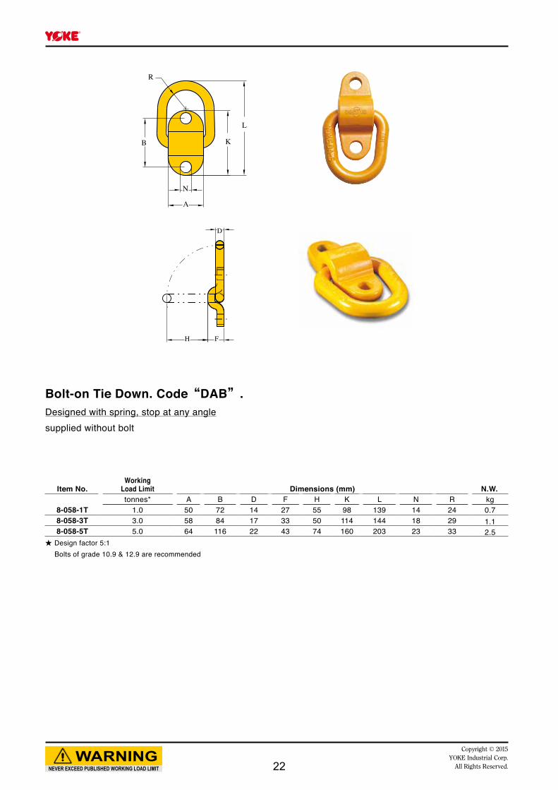
Load Limit Dimensions (mm) N.W.tonnes* A B D F H K L N R kg
8-058-1T 1.0 50 72 14 27 55 98 139 14 24 0.78-058-3T 3.0 58 84 17 33 50 114 144 18 29 1.18-058-5T 5.0 64 116 22 43 74 160 203 23 33 2.5
★ Design factor 5:1 Bolts of grade 10.9 & 12.9 are recommended
NEVER EXCEED PUBLISHED WORKING LOAD LIMITWARNING
Copyright © 2015YOKE Industrial Corp.
All Rights Reserved.
A
N
K
L
B
R
H F
D
Bolt-on Tie Down. Code“DAB”.Designed with spring, stop at any anglesupplied without bolt
22
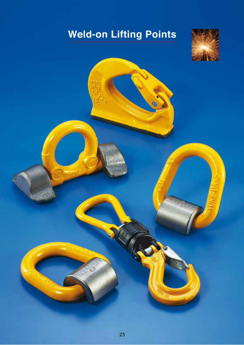
Weld-on Lifting Points
23
NEVER EXCEED PUBLISHED WORKING LOAD LIMITWARNING
Copyright © 2015YOKE Industrial Corp.
All Rights Reserved.
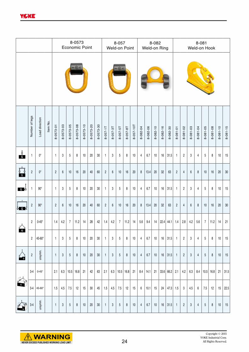
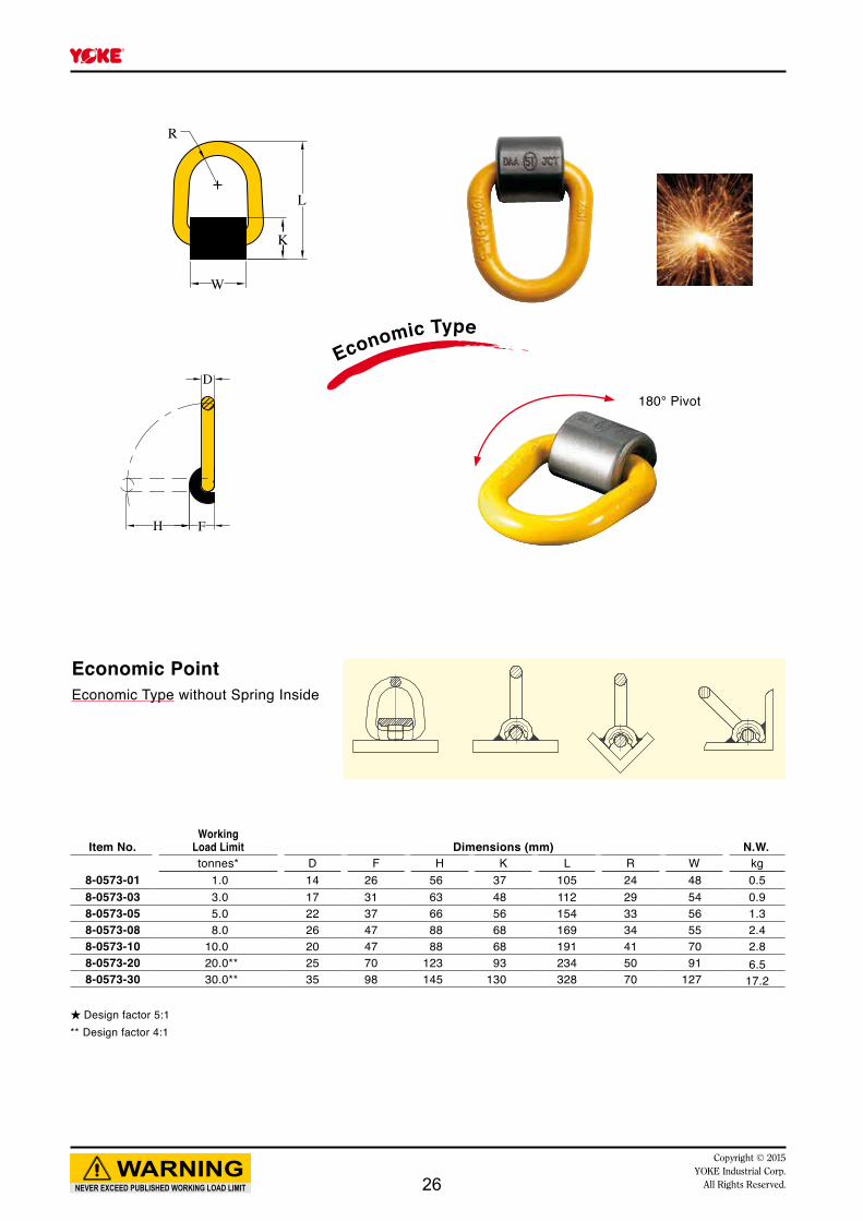
8-0573Economic Point
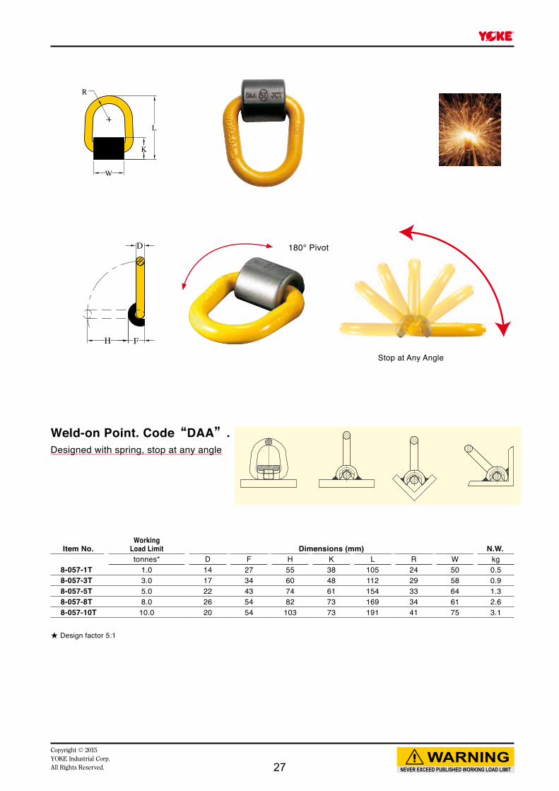
8-057 Weld-on Point
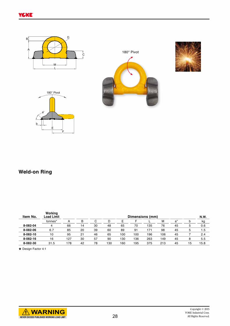
8-082Weld-on Ring
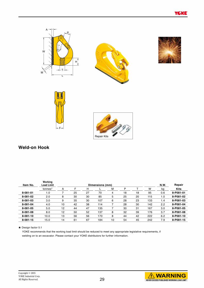
8-081Weld-on Hook
Num
ber o
f leg
s
Load
dire
ctio
n
Item
No.
1 0° 1 3 5 8 10 20 30 1 3 5 8 10 4 6.7 10 16 31.5 1 2 3 4 5 8 10 15
2 0° 2 6 10 16 20 40 60 2 6 10 16 20 8 13.4 20 32 63 2 4 6 8 10 16 20 30
1 90° 1 3 5 8 10 20 30 1 3 5 8 10 4 6.7 10 16 31.5 1 2 3 4 5 8 10 15
2 90° 2 6 10 16 20 40 60 2 6 10 16 20 8 13.4 20 32 63 2 4 6 8 10 16 20 30
2 0-45° 1.4 4.2 7 11.2 14 28 42 1.4 4.2 7 11.2 14 5.6 9.4 14 22.4 44.1 1.4 2.8 4.2 5.6 7 11.2 14 21
2 45-60° 1 3 5 8 10 20 30 1 3 5 8 10 4 6.7 10 16 31.5 1 2 3 4 5 8 10 15
2
unsy
mm.
1 3 5 8 10 20 30 1 3 5 8 10 4 6.7 10 16 31.5 1 2 3 4 5 8 10 15
3-4 0-45° 2.1 6.3 10.5 16.8 21 42 63 2.1 6.3 10.5 16.8 21 8.4 14.1 21 33.6 66.2 2.1 4.2 6.3 8.4 10.5 16.8 21 31.5
3-4 45-60° 1.5 4.5 7.5 12 15 30 45 1.5 4.5 7.5 12 15 6 10.1 15 24 47.3 1.5 3 4.5 6 7.5 12 15 22.5
3-4
unsy
mm.
1 3 5 8 10 20 30 1 3 5 8 10 4 6.7 10 16 31.5 1 2 3 4 5 8 10 15
8-05
73-0
1
8-05
73-0
3
8-05
73-0
5
8-05
73-0
8
8-05
73-1
0
8-05
73-2
0
8-05
73-3
0
8-05
7-1T
8-05
7-3T
8-05
7-5T
8-05
7-8T
8-05
7-10
T
8-08
2-04
8-08
2-06
8-08
2-10
8-08
2-16
8-08
2-30
8-08
1-01
8-08
1-02
8-08
1-03
8-08
1-04
8-08
1-05
8-08
1-08
8-08
1-10
8-08
1-15
24
NEVER EXCEED PUBLISHED WORKING LOAD LIMITWARNING
Copyright © 2015YOKE Industrial Corp.All Rights Reserved.
WELDING INSTRUCTIONS
The welding should only be carried out by qualified welder according to Standards, e.g. EN 287 or AWS.
Support material ● Material of the welding block is S355J2+N (1.0577+N, St 52-3N, B.S. 4360.50D, AISI 1019 etc.).
● Prior to welding, the contact areas must be free from impurities, oil, paint, rust, scale, etc., for example by grinding. If the surface is at all corroded, all rust must be completely removed from the weld area. Painted surface must be prepared in the same way.
● The steel support member must have a carbon content of no more than 0.40%.
● In ambient temperature of 10ºC and below, pre-heating of the weld area prior to welding must be carried out.
Seam welding ● The welds must be sufficiently strong to take the required loads.
● Before starting the final weld pass, clean well the root pass to avoid inclusions.
● The complete welding operation must be carried out continuously so that the parts do not have time to cool.
● Effects of temperature
• The complete construction can be annealed stress release at <600°C without reduction of WLL.
• Do not rapidly cool the weld.
● A thorough inspection of the weld should be performed. No cracks, pitting, inclusions, notches or undercuts are allowed. If doubt exists, use a suitable NDT method, such as magnetic particle or liquid penetrant to verify.
● If repair is required, grind out the defect and re-weld using the original qualified procedure.
Welding materials ● Weld materials must have a minimum tensile strength of 70,000 PSI (such as AWS A5.1 E-7018), following the electrode manufacturer’s recommendations. Reference information as below:
MIG arc welding:
• Wire diameter 0.8 - 1.2 as per DIN 8559-SG 3, AWS A 5.18.
• Important: do not weld in the open air during bad weather
25
NEVER EXCEED PUBLISHED WORKING LOAD LIMITWARNING
Copyright © 2015YOKE Industrial Corp.
All Rights Reserved.
Item No.Working
Load Limit Dimensions (mm) N.W.tonnes* D F H K L R W kg
8-0573-01 1.0 14 26 56 37 105 24 48 0.58-0573-03 3.0 17 31 63 48 112 29 54 0.98-0573-05 5.0 22 37 66 56 154 33 56 1.38-0573-08 8.0 26 47 88 68 169 34 55 2.48-0573-10 10.0 20 47 88 68 191 41 70 2.88-0573-20 20.0** 25 70 123 93 234 50 91 6.58-0573-30 30.0** 35 98 145 130 328 70 127 17.2
★ Design factor 5:1** Design factor 4:1
D
FH
R
W
K
L
180° Pivot
Economic PointEconomic Type without Spring Inside
Economic Type
26
NEVER EXCEED PUBLISHED WORKING LOAD LIMITWARNING
Copyright © 2015YOKE Industrial Corp.All Rights Reserved.
Item No.Working
Load Limit Dimensions (mm) N.W.tonnes* D F H K L R W kg
8-057-1T 1.0 14 27 55 38 105 24 50 0.58-057-3T 3.0 17 34 60 48 112 29 58 0.98-057-5T 5.0 22 43 74 61 154 33 64 1.38-057-8T 8.0 26 54 82 73 169 34 61 2.68-057-10T 10.0 20 54 103 73 191 41 75 3.1
★ Design factor 5:1
R
W
K
L
D
FH
180° Pivot
Stop at Any Angle
Weld-on Point. Code“DAA”.Designed with spring, stop at any angle
27
B
A
L
180° Pivot
°
FE
b
a
M
D
C180° Pivot
NEVER EXCEED PUBLISHED WORKING LOAD LIMITWARNING
Copyright © 2015YOKE Industrial Corp.
All Rights Reserved.
Weld-on Ring
★ Design Factor 4:1
Item No.Working
Load Limit Dimensions (mm) N.W.tonnes* A B C D E F L M a° b kg
8-082-04 4 66 14 30 48 65 70 135 76 45 5 0.6 8-082-06 6.7 85 20 39 60 89 91 171 98 45 5 1.58-082-10 10 95 21 46 65 100 100 196 106 45 7 2.48-082-16 16 127 30 57 90 130 136 263 149 45 8 5.58-082-30 31.5 178 42 78 130 160 195 375 213 45 15 15.8
28
A
W
ML
T
H
P
F
Item No.Working
Load Limit Dimensions (mm) N.W. RepairKitstonnes* A F H L M P T W kg
8-081-01 1.0 7 25 27 70 4 18 18 95 0.6 8-P081-018-081-02 2.0 8 30 30 85 5 25 20 115 1.0 8-P081-028-081-03 3.0 9 35 30 107 6 28 23 133 1.4 8-P081-038-081-04 4.0 10 42 38 114 7 28 30 142 2.2 8-P081-048-081-05 5.0 12 44 47 135 7 30 31 167 3.0 8-P081-058-081-08 8.0 12 50 52 137 8 32 39 176 3.7 8-P081-088-081-10 10.0 13 56 56 170 8 44 42 222 6.2 8-P081-108-081-15 15.0 14 61 67 184 10 54 45 242 7.9 8-P081-15
NEVER EXCEED PUBLISHED WORKING LOAD LIMITWARNING
Copyright © 2015YOKE Industrial Corp.All Rights Reserved.
Weld-on Hook
★ Design factor 5:1YOKE recommends that the working load limit should be reduced to meet any appropriate legislative requirements, if welding on to an excavator. Please contact your YOKE distributors for further information.
Repair Kits
29
NEVER EXCEED PUBLISHED WORKING LOAD LIMITWARNING
Copyright © 2015YOKE Industrial Corp.
All Rights Reserved.
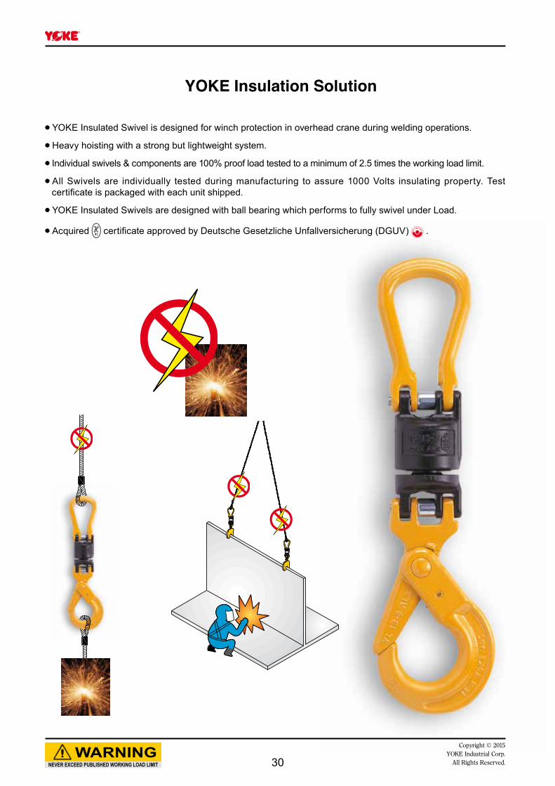
YOKE Insulation Solution
● YOKE Insulated Swivel is designed for winch protection in overhead crane during welding operations.
● Heavy hoisting with a strong but lightweight system.
● Individual swivels & components are 100% proof load tested to a minimum of 2.5 times the working load limit.
● All Swivels are individually tested during manufacturing to assure 1000 Volts insulating property. Test certificate is packaged with each unit shipped.
● YOKE Insulated Swivels are designed with ball bearing which performs to fully swivel under Load.
● Acquired certificate approved by Deutsche Gesetzliche Unfallversicherung (DGUV) .
30
L
AD
NEVER EXCEED PUBLISHED WORKING LOAD LIMITWARNING
Copyright © 2015YOKE Industrial Corp.All Rights Reserved.
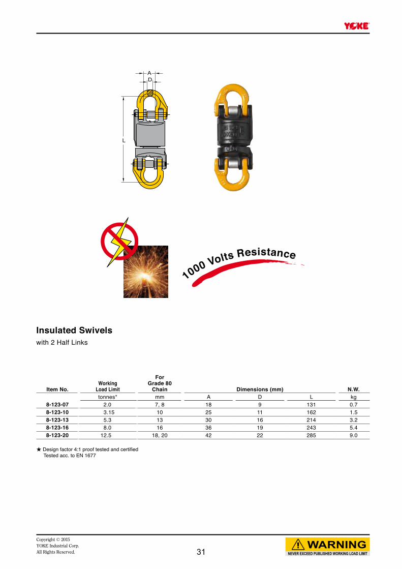
Insulated Swivelswith 2 Half Links
Item No.Working
Load Limit
ForGrade 80
Chain Dimensions (mm) N.W.tonnes* mm A D L kg
8-123-07 2.0 7, 8 18 9 131 0.78-123-10 3.15 10 25 11 162 1.58-123-13 5.3 13 30 16 214 3.28-123-16 8.0 16 36 19 243 5.48-123-20 12.5 18, 20 42 22 285 9.0
★ Design factor 4:1 proof tested and certified Tested acc. to EN 1677
1000 Volts Resistance
31
L
W
H
T
t
NEVER EXCEED PUBLISHED WORKING LOAD LIMITWARNING
Copyright © 2015YOKE Industrial Corp.
All Rights Reserved.
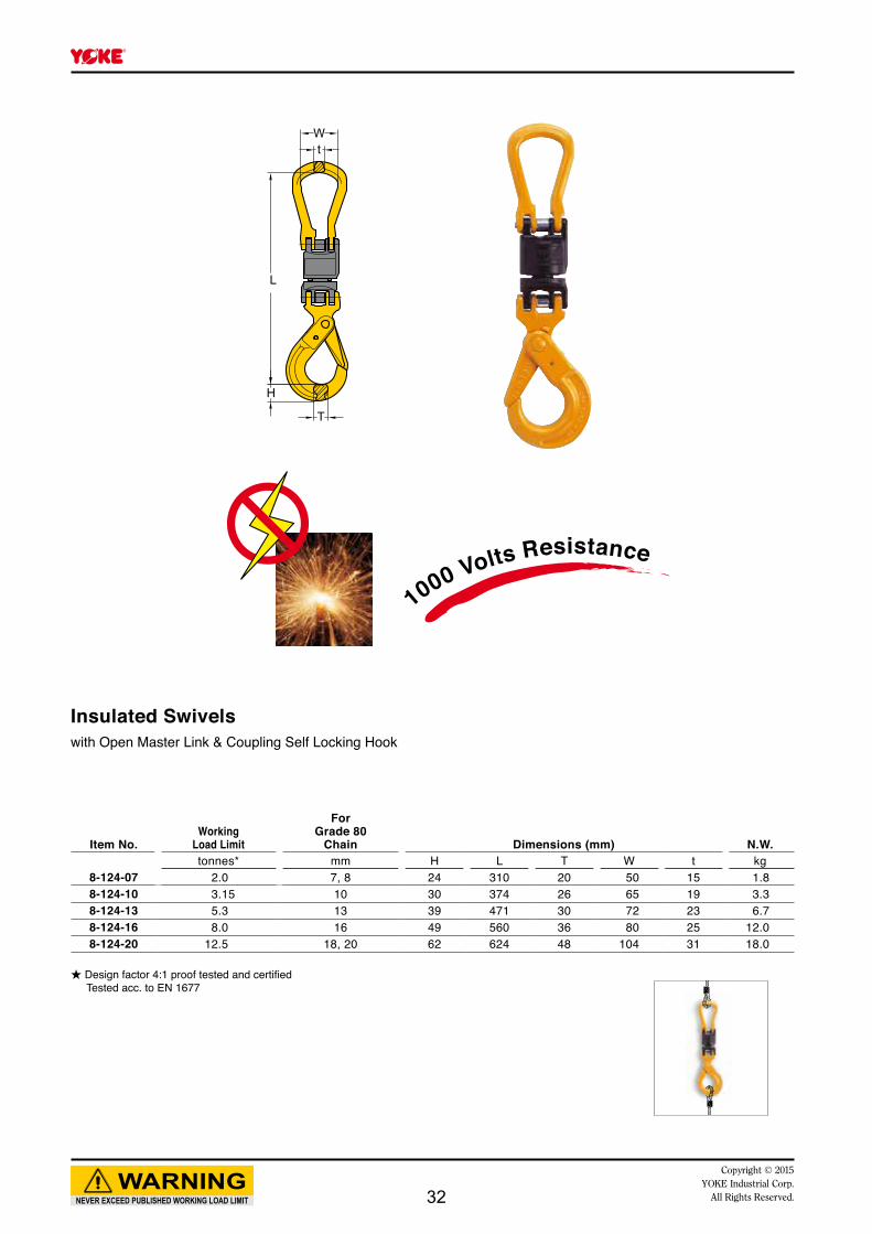
Insulated Swivelswith Open Master Link & Coupling Self Locking Hook
Item No.Working
Load Limit
ForGrade 80
Chain Dimensions (mm) N.W.tonnes* mm H L T W t kg
8-124-07 2.0 7, 8 24 310 20 50 15 1.88-124-10 3.15 10 30 374 26 65 19 3.38-124-13 5.3 13 39 471 30 72 23 6.78-124-16 8.0 16 49 560 36 80 25 12.08-124-20 12.5 18, 20 62 624 48 104 31 18.0
★ Design factor 4:1 proof tested and certified Tested acc. to EN 1677
1000 Volts Resistance
32
W
t
L
H
T
NEVER EXCEED PUBLISHED WORKING LOAD LIMITWARNING
Copyright © 2015YOKE Industrial Corp.All Rights Reserved.
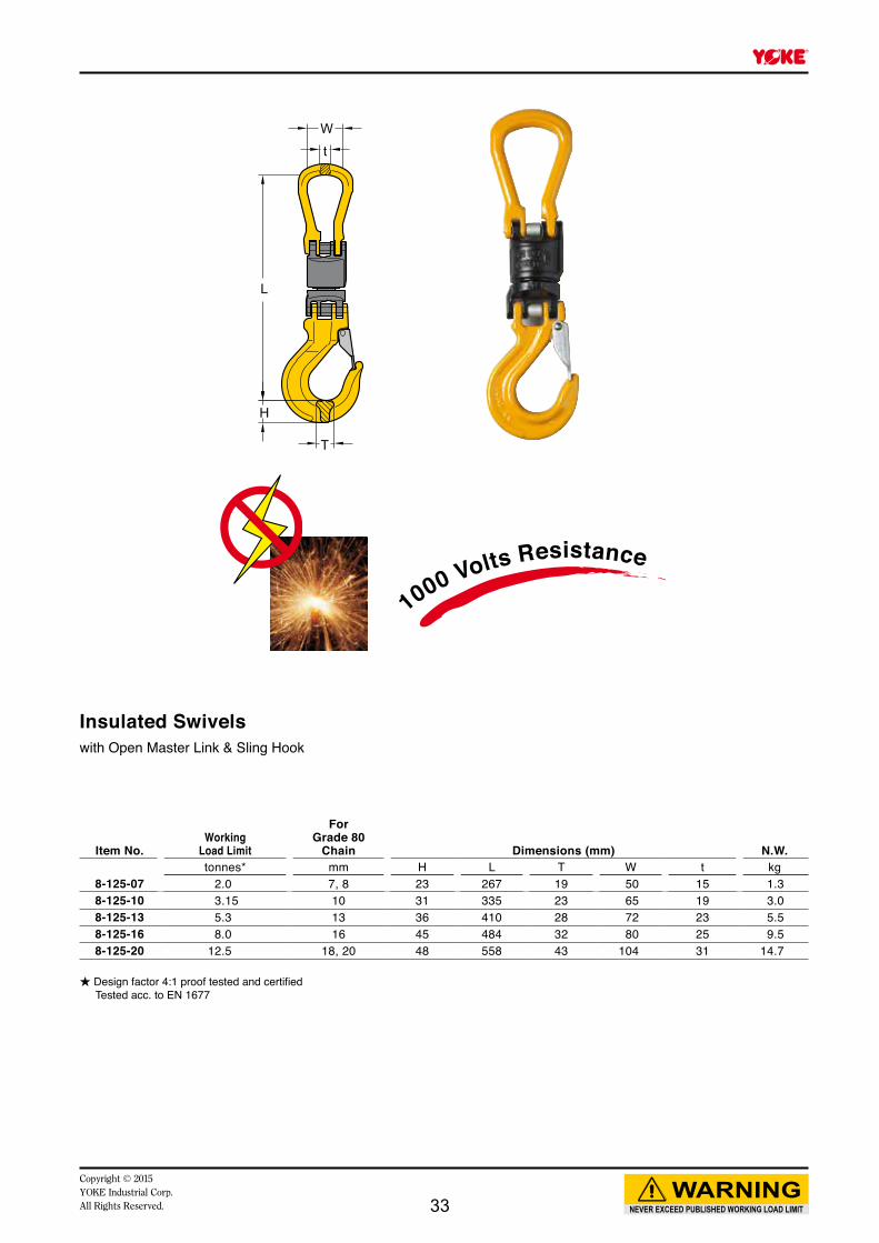
Insulated Swivelswith Open Master Link & Sling Hook
Item No.Working
Load Limit
ForGrade 80
Chain Dimensions (mm) N.W.tonnes* mm H L T W t kg
8-125-07 2.0 7, 8 23 267 19 50 15 1.38-125-10 3.15 10 31 335 23 65 19 3.08-125-13 5.3 13 36 410 28 72 23 5.58-125-16 8.0 16 45 484 32 80 25 9.58-125-20 12.5 18, 20 48 558 43 104 31 14.7
★ Design factor 4:1 proof tested and certified Tested acc. to EN 1677
1000 Volts Resistance
33

NEVER EXCEED PUBLISHED WORKING LOAD LIMITWARNING
Copyright © 2015YOKE Industrial Corp.
All Rights Reserved.
NOTE
34
Yellow Point
NEVER EXCEED PUBLISHED WORKING LOAD LIMITWARNING
Copyright © 2015YOKE Industrial Corp.All Rights Reserved. 35

www.yoke.net
YOKE products distributed by:
An ISO 9001 Registered Company
YOKE INDUSTRIAL CORP. #39, 33rd Road,
Taichung Industrial Park, Taichung 407,
TAIWAN Tel:+886-4-2350-8088 Fax:+886-4-2350-1001
E-mail: [email protected]