YEAR 2013 ONE MARK - mywbut.com chapter wise solved papers... · GATE SOLVED PAPER - EE ELECTRICAL...
54
GATE SOLVED PAPER - EE ELECTRICAL MACHINES YEAR 2013 ONE MARK Q. 1 Leakage flux in an induction motor is (A) flux that leaks through the machine (B) flux that links both stator and rotor windings (C) flux that links none of the windings (D) flux that links the stator winding or the rotor winding but not both Q. 2 The angle d in the swing equation of a synchronous generator is the (A) angle between stator voltage and current (B) angular displacement of the rotor with respect to the stator (C) angular displacement of the stator mmf with respect to a synchronously rotating axis. (D) angular displacement of an axis fixed to the rotor with respect to a synchronously rotating axis Q. 3 A single-phase transformer has no-load loss of 64 W, as obtained from an open circuit test. When a short-circuit test is performed on it with 90% of the rated currents flowing in its both LV and HV windings, he measured loss is 81 W. The transformer has maximum efficiency when operated at (A) 50.0% of the rated current (B) 64.0% of the rated current (C) 80.0% of the rated current (D) 88.8% of the rated current YEAR 2013 TWO MARKS Q. 4 A 4-pole induction motor, supplied by a slightly unbalanced three-phase 50 Hz source, is rotating at 1440 rpm. The electrical frequency in Hz of the induced negative sequence current in the rotor is (A) 100 (B) 98 (C) 52 (D) 48 Q. 5 The following arrangement consists of an ideal transformer and an attenuator which attenuates by a factor of 0.8. An ac voltage 100 V V WX1 = is applied across WX to get an open circuit voltage V YZ1 across YZ. Next, an ac voltage 100 V V YZ2 = is applied across YZ to get an open circuit voltage V WX2 across WX. Then, / V V YZ WX 1 1 , / V V WX YZ 2 2 are respectively, mywbut.com
Transcript of YEAR 2013 ONE MARK - mywbut.com chapter wise solved papers... · GATE SOLVED PAPER - EE ELECTRICAL...

GATE SOLVED PAPER - EEELECTRICAL MACHINES
YEAR 2013 ONE MARK
Q. 1 Leakage flux in an induction motor is(A) flux that leaks through the machine
(B) flux that links both stator and rotor windings
(C) flux that links none of the windings
(D) flux that links the stator winding or the rotor winding but not both
Q. 2 The angle d in the swing equation of a synchronous generator is the(A) angle between stator voltage and current
(B) angular displacement of the rotor with respect to the stator
(C) angular displacement of the stator mmf with respect to a synchronously rotating axis.
(D) angular displacement of an axis fixed to the rotor with respect to a synchronously rotating axis
Q. 3 A single-phase transformer has no-load loss of 64 W, as obtained from an open circuit test. When a short-circuit test is performed on it with 90% of the rated currents flowing in its both LV and HV windings, he measured loss is 81 W. The transformer has maximum efficiency when operated at(A) 50.0% of the rated current
(B) 64.0% of the rated current
(C) 80.0% of the rated current
(D) 88.8% of the rated current
YEAR 2013 TWO MARKS
Q. 4 A 4-pole induction motor, supplied by a slightly unbalanced three-phase 50 Hz source, is rotating at 1440 rpm. The electrical frequency in Hz of the induced negative sequence current in the rotor is(A) 100
(B) 98
(C) 52
(D) 48
Q. 5 The following arrangement consists of an ideal transformer and an attenuator which attenuates by a factor of 0.8. An ac voltage 100 VVWX1 = is applied across WX to get an open circuit voltage VYZ1 across YZ. Next, an ac voltage
100 VVYZ2 = is applied across YZ to get an open circuit voltage VWX2 across WX. Then, /V VYZ WX1 1, /V VWX YZ2 2 are respectively,
mywbut.com

GATE SOLVED PAPER - EE ELECTRICAL MACHINES
(A) 125/100 and 80/100 (B) 100/100 and 80/100
(C) 100/100 and 100/100 (D) 80/100 and 80/100
YEAR 2012 ONE MARK
Q. 6 The slip of an induction motor normally does not depend on(A) rotor speed (B) synchronous speed
(C) shaft torque (D) core-loss component
YEAR 2012 TWO MARKS
Q. 7 A 220 ,V 15 ,kW 100 rpm shunt motor with armature resistance of 0.25 ,W has a rated line current of 68 A and a rated field current of 2.2 A. The change in field flux required to obtain a speed of 1600 rpm while drawing a line current of 52.8 A and a field current of 1.8 A is(A) 18.18% increase (B) 18.18% decrease
(C) 36.36% increase (D) 36.36% decrease
Q. 8 The locked rotor current in a 3-phase, star connected 15 ,kW 4 ,pole ,V230 50 Hz induction motor at rated conditions is 50 A. Neglecting losses and magnetizing current, the approximate locked rotor line current drawn when the motor is connected to a 236 ,V Hz57 supply is(A) 58.5 A (B) 45.0 A
(C) 42.7 A (D) 55.6 A
Q. 9 A single phase 10 ,kVA 50 Hz transformer with 1 kV primary winding draws 0.5 A and 55 ,W at rated voltage and frequency, on no load. A second transformer has a core with all its linear dimensions 2 times the corresponding dimensions of the first transformer. The core material and lamination thickness are the same in both transformer. The primary winding of both the transformers have the save number of turns. If a rate voltage of 2 kV at 50 Hz is applied to the primary of the second transformer, then the no load current and power, respectively, are(A) 0.7 ,A 77.8 A (B) 0.7 ,A 155.6 W
(C) 1 ,A 110 W (D) 1 ,A 220 W
YEAR 2011 ONE MARK
Q. 10 A 4 point starter is used to start and control the speed of a(A) dc shunt motor with armature resistance control
(B) dc shunt motor with field weakening control
(C) dc series motor
(D) dc compound motor
mywbut.com

GATE SOLVED PAPER - EE ELECTRICAL MACHINES
Q. 11 A three phase, salient pole synchronous motor is connected to an infinite bus. It is operated at no load a normal excitation. The field excitation of the motor is first reduced to zero and then increased in reverse direction gradually. Then the armature current.(A) Increases continuously
(B) First increases and then decreases steeply
(C) First decreases and then increases steeply
(D) Remains constant
Q. 12 A single phase air core transformer, fed from a rated sinusoidal supply, is operating at no load. The steady state magnetizing current drawn by the transformer from the supply will have the waveform
YEAR 2011 TWO MARKS
Q. 13 A 220 V, DC shunt motor is operating at a speed of 1440 rpm. The armature resistance is .1 0W and armature current is 10 A. of the excitation of the machine is reduced by 10%, the extra resistance to be put in the armature circuit to maintain the same speed and torque will be(A) .1 79W (B) .2 1W(C) .18 9W (D) .3 1W
Q. 14 A three-phase 440 V, 6 pole, 50 Hz, squirrel cage induction motor is running at a slip of 5%. The speed of stator magnetic field to rotor magnetic field and speed of rotor with respect of stator magnetic field are(A) zero, 5 rpm-(B) zero, 955 rpm
(C) 1000 rpm, 5 rpm-(D) 1000 rpm, 955 rpm
mywbut.com

GATE SOLVED PAPER - EE ELECTRICAL MACHINES
YEAR 2010 ONE MARK
Q. 15 A Single-phase transformer has a turns ratio 1:2, and is connected to a purely resistive load as shown in the figure. The magnetizing current drawn is 1 A, and the secondary current is 1 A. If core losses and leakage reactances are neglected, the primary current is
(A) 1.41 A
(B) 2 A
(C) 2.24 A
(D) 3 A
Q. 16 A balanced three-phase voltage is applied to a star-connected induction motor, the phase to neutral voltage being V . The stator resistance, rotor resistance referred to the stator, stator leakage reactance, rotor leakage reactance referred to the stator, and the magnetizing reactance are denoted by rs , rr , Xs , Xr and Xm , respectively. The magnitude of the starting current of the motor is given by
(A) ( ) ( )r r X X
Vs r s r
s2 2+ + +
(B) ( )r X XV
s s m
s2 2+ +
(C) ( ) ( )r r X X
Vs r m r
s2 2+ + +
(D) ( )r X XV
s m r
s2 2+ +
YEAR 2010 TWO MARKS
Q. 17 A separately excited dc machine is coupled to a 50 Hz, three-phase, 4-pole induction machine as shown in figure. The dc machine is energized first and the machines rotate at 1600 rpm. Subsequently the induction machine is also connected to a 50 Hz, three-phase source, the phase sequence being consistent with the direction of rotation. In steady state
(A) both machines act as generator
(B) the dc machine acts as a generator, and the induction machine acts as a motor
(C) the dc machine acts as a motor, and the induction machine acts as a generator
(D) both machines act as motors
mywbut.com

GATE SOLVED PAPER - EE ELECTRICAL MACHINES
Common Data for Questions 18 and 19A separately excited DC motor runs at 1500 rpm under no-load with 200 V applied to the armature. The field voltage is maintained at its rated value. The speed of the motor, when it delivers a torque of5 Nm, is 1400 rpm as shown in figure. The rotational losses and armature reaction are neglected.
Q. 18 The armature resistance of the motor is(A) 2 W (B) 3.4 W(C) 4.4 W (D) 7.7 W
Q. 19 For the motor to deliver a torque of 2.5 Nm at 1400 rpm, the armature voltage to be applied is(A) 125.5 V (B) 193.3 V
(C) 200 V (D) 241.7 V
Q. 20 A balanced star-connected and purely resistive load is connected at the secondary of a star-delta transformer as shown in figure. The line-to line voltage rating of the transformer is 110 V/200 V.Neglecting the non-idealities of the transformer, the impedance Z of the equivalent star-connected load, referred to the primary side of the transformer, is
mywbut.com

GATE SOLVED PAPER - EE ELECTRICAL MACHINES
(A) ( )j3 0 W+ (B) ( . . )j0 866 0 5 W-(C) ( . . )j0 866 0 5 W+ (D) (1 0)j W+
YEAR 2009 ONE MARK
Q. 21 A field excitation of 20 A in a certain alternator results in an armature current of 400 A in short circuit and a terminal voltage of 2000 V on open circuit. The magnitude of the internal voltage drop within the machine at a load current of 200 A is(A) 1 V (B) 10 V
(C) 100 V (D) 1000 V
Q. 22 The single phase, 50 Hz iron core transformer in the circuit has both the vertical arms of cross sectional area 20 cm2 and both the horizontal arms of cross sectional area 10 cm2. If the two windings shown were wound instead on opposite horizontal arms, the mutual inductance will
(A) double (B) remain same
(C) be halved (D) become one quarter
Q. 23 A 3-phase squirrel cage induction motor supplied from a balanced 3-phase source drives a mechanical load. The torque-speed characteristics of the motor(solid curve) and of theload(dotted curve) are shown. Of the two equilibrium points A and B, which of the following options correctly describes the stability of A and B ?
(A) A is stable, B is unstable (B) A is unstable, B is stable
(C) Both are stable (D) Both are unstable
YEAR 2009 TWO MARKS
Q. 24 A 200 V, 50 Hz, single-phase induction motor has the following connection diagram and winding orientations as shown. MM’ is the axis of the main stator winding(M M )1 2 and AA’ is that of the auxiliary winding(A A )1 2 . Directions of the winding axis indicate direction of flux when currents in the windings are in the directions shown. Parameters of each winding are indicated. When switch S is closed the motor
mywbut.com

GATE SOLVED PAPER - EE ELECTRICAL MACHINES
(A) rotates clockwise
(B) rotates anti-clockwise
(C) does not rotate
(D) rotates momentarily and comes to a halt
Common Data for Questions 25 and 26 :The circuit diagram shows a two-winding, lossless transformer with no leakage flux, excited from a current source, ( )i t , whose waveform is also shown. The transformer has a magnetizing inductance of
/400 p mH.
Q. 25 The peak voltage across A and B, with S open is
(A) 400p
V (B) 800 V
(C) 4000p
V (D) 800p
V
Q. 26 If the wave form of ( )i t is changed to ( ) 10 (100 )sini t tp= A, the peak voltage across A and B with S closed is(A) 400 V (B) 240 V
(C) 320 V (D) 160 V
mywbut.com

GATE SOLVED PAPER - EE ELECTRICAL MACHINES
Common Data for Questions 27 and 28:
The star-delta transformer shown above is excited on the star side with balanced, 4-wire, 3-phase, sinusoidal voltage supply of rated magnitude. The transformer is under no load condition
Q. 27 With both S1 and S2 open, the core flux waveform will be(A) a sinusoid at fundamental frequency
(B) flat-topped with third harmonic
(C) peaky with third-harmonic
(D) none of these
Q. 28 With S2 closed and S1 open, the current waveform in the delta winding will be(A) a sinusoid at fundamental frequency
(B) flat-topped with third harmonic
(C) only third-harmonic
(D) none of these
Q. 29 Figure shows the extended view of a 2-pole dc machine with 10 armature conductors. Normal brush positions are shown by A and B, placed at the interpolar axis. If the brushes are now shifted, in the direction of rotation, to A’ and B’ as shown, the voltage waveform V ' 'A B will resemble
mywbut.com

GATE SOLVED PAPER - EE ELECTRICAL MACHINES
Statement for Linked Answer Questions 30 and 31 :
The figure above shows coils-1 and 2, with dot markings as shown, having 4000 and 6000 turns respectively. Both the coils have a rated current of 25 A. Coil-1 is excited with single phase, 400 V, 50 Hz supply.
Q. 30 The coils are to be connected to obtain a single-phase, 1000400 V,
auto-transformer to drive a load of 10 kVA. Which of the options given should be exercised to realize the required auto-transformer ?(A) Connect A and D; Common B (B) Connect B and D; Common C
(C) Connect A and C; Common B (D) Connect A and C; Common D
Q. 31 In the autotransformer obtained in Question 16, the current in each coil is(A) Coil-1 is 25 A and Coil-2 is 10 A
(B) Coil-1 is 10 A and Coil-2 is 25 A
(C) Coil-1 is 10 A and Coil-2 is 15 A
(D) Coil-1 is 15 A and Coil-2 is 10 A
YEAR 2008 ONE MARK
Q. 32 Distributed winding and short chording employed in AC machines will result in(A) increase in emf and reduction in harmonics
(B) reduction in emf and increase in harmonics
(C) increase in both emf and harmonics
(D) reduction in both emf and harmonics
Q. 33 Three single-phase transformer are connected to form a 3-phase transformer bank. The transformers are connected in the following manner :
The transformer connecting will be represented by(A) Y d0 (B) Y d1
(C) Y d6 (D) Y d11
Q. 34 In a stepper motor, the detent torque means(A) minimum of the static torque with the phase winding excited
(B) maximum of the static torque with the phase winding excited
(C) minimum of the static torque with the phase winding unexcited
(D) maximum of the static torque with the phase winding unexcited
mywbut.com

GATE SOLVED PAPER - EE ELECTRICAL MACHINES
Q. 35 It is desired to measure parameters of 230 V/115 V, 2 kVA,single-phase transformer. The following wattmeters are available in a laboratory:W1 : 250 V, 10 A, Low Power FactorW2 : 250 V, 5 A, Low Power FactorW3 : 150 V, 10 A, High Power FactorW4 : 150 V, 5 A, High Power FactorThe Wattmeters used in open circuit test and short circuit test of the transformer will respectively be(A) W1 and W2
(B) W2 and W4
(C) W1 and W4
(D) W2 and W3
YEAR 2008 TWO MARKS
Q. 36 A 230 V, 50 Hz, 4-pole, single-phase induction motor is rotating in the clockwise (forward) direction at a speed of 1425 rpm. If the rotor resistance at standstill is 7.8 W, then the effective rotor resistance in the backward branch of the equivalent circuit will be(A) 2 W(B) 4 W(C) 78 W(D) 156 W
Q. 37 A 400 V, 50 Hz 30 hp, three-phase induction motor is drawing50 A current at 0.8 power factor lagging. The stator and rotor copper losses are 1.5 kW and 900 W respectively. The friction and windage losses are 1050 W and the core losses are 1200 W. The air-gap power of the motor will be(A) 23.06 kW
(B) 24.11 kW
(C) 25.01 kW
(D) 26.21 kW
Q. 38 The core of a two-winding transformer is subjected to a magnetic flux variation as indicated in the figure.
The induced emf ( )ers in the secondary winding as a function of time will be of the form
mywbut.com

GATE SOLVED PAPER - EE ELECTRICAL MACHINES
Q. 39 A 400 V, 50 Hz, 4-pole, 1400 rpm, star connected squirrel cage induction motor has the following parameters referred to the stator:
1.0 , 1.5R X X'r s rW W= = =
Neglect stator resistance and core and rotational losses of the motor. The motor is controlled from a 3-phase voltage source inverter with constant /V f control. The stator line-to-line voltage(rms) and frequency to obtain the maximum torque at starting will be :(A) 20.6 V, 2.7 Hz
(B) 133.3 V, 16.7 Hz
(C) 266.6 V, 33.3 Hz
(D) 323.3 V, 40.3 Hz
Common Data for Questions 40 and 41.A 3-phase, 440 V, 50 Hz, 4-pole slip ring induction motor is feed from the rotor side through an auto-transformer and the stator is connected to a variable resistance as shown in the figure.
The motor is coupled to a 220 V, separately excited d.c generator feeding power to fixed resistance of 10 W. Two-wattmeter method is used to measure the input power to induction motor. The variable resistance is adjusted such the motor runs at 1410 rpm and the following readings were recorded 1800W1 = W, 200W2 =- W.
mywbut.com

GATE SOLVED PAPER - EE ELECTRICAL MACHINES
Q. 40 The speed of rotation of stator magnetic field with respect to rotor structure will be(A) 90 rpm in the direction of rotation
(B) 90 rpm in the opposite direction of rotation
(C) 1500 rpm in the direction of rotation
(D) 1500 rpm in the opposite direction of rotation
Q. 41 Neglecting all losses of both the machines, the dc generator power output and the current through resistance ( )Rex will respectively be(A) 96 W, 3.10 A (B) 120 W, 3.46 A
(C) 1504 W, 12.26 A (D) 1880 W, 13.71 A
Statement for Linked Answer Question 42 and 43.A 240 V, dc shunt motor draws 15 A while supplying the rated load at a speed of 80 rad/s. The armature resistance is 0.5 W and the field winding resistance is 80 W.
Q. 42 The net voltage across the armature resistance at the time of plugging will be(A) 6 V (B) 234 V
(C) 240 V (D) 474 V
Q. 43 The external resistance to be added in the armature circuit to limit the armature current to 125% of its rated value is(A) 31.1 W (B) 31.9 W(C) 15.1 W (D) 15.9 W
Statement for Linked Answer Question 44 and 45.A synchronous motor is connected to an infinite bus at 1.0 pu voltage and draws 0.6 pu current at unity power factor. Its synchronous reactance is 1.0 pu resistance is negligible.
Q. 44 The excitation voltage (E ) and load angle ( )d will respectively be(A) 0.8 pu and 36.86c lag (B) 0.8 pu and 36.86c lead
(C) 1.17 pu and 30.96c lead (D) 1.17 pu and 30.96c lag
Q. 45 Keeping the excitation voltage same, the load on the motor is increased such that the motor current increases by 20%. The operating power factor will become(A) 0.995 lagging (B) 0.995 leading
(C) 0.791 lagging (D) 0.848 leading
YEAR 2007 ONE MARK
Q. 46 In a transformer, zero voltage regulation at full load is(A) not possible
(B) possible at unity power factor load
(C) possible at leading power factor load
(D) possible at lagging power factor load
mywbut.com

GATE SOLVED PAPER - EE ELECTRICAL MACHINES
Q. 47 The dc motor, which can provide zero speed regulation at full load without any controller is(A) series
(B) shunt
(C) cumulative compound
(D) differential compound
Q. 48 The electromagnetic torque Te of a drive and its connected load torque TL are as shown below. Out of the operating points A, B, C and D, the stable ones are
(A) A, C, D (B) B, C
(C) A, D (D) B, C, D
YEAR 2007 TWO MARKS
Q. 49 A three-phase synchronous motor connected to ac mains is running at full load and unity power factor. If its shaft load is reduced by half, with field current held constant, its new power factor will be(A) unity
(B) leading
(C) lagging
(D) dependent on machine parameters
Q. 50 A 100 kVA, 415 V(line), star-connected synchronous machine generates rated open circuit voltage of 415 V at a field current of 15 A. The short circuit armature current at a field current of10 A is equal to the rated armature current. The per unit saturated synchronous reactance is(A) 1.731 (B) 1.5
(C) 0.666 (D) 0.577
Q. 51 A single-phase, 50 kVA, 250 V/500 V two winding transformer has an efficiency of 95% at full load, unity power factor. If it is re-configured as a 500 V/750 V auto-transformer, its efficiency at its new rated load at unity power factor will be(A) 95.752% (B) 97.851%
(C) 98.276% (D) 99.241%
mywbut.com

GATE SOLVED PAPER - EE ELECTRICAL MACHINES
Q. 52 A three-phase, three-stack, variable reluctance step motor has 20 poles on each rotor and stator stack. The step angle of this step motor is(A) 3c (B) 6c
(C) 9c (D) 81 c
Q. 53 A three-phase squirrel cage induction motor has a starting torque of 150% and a maximum torque of 300% with respect to rated torque at rated voltage and rated frequency. Neglect the stator resistance and rotational losses. The value of slip for maximum torque is(A) 13.48% (B) 16.42%
(C) 18.92% (D) 26.79%
Common Data for Question 54, 55 and 56:A three phase squirrel cage induction motor has a starting current of seven times the full load current and full load slip of 5%
Q. 54 If an auto transformer is used for reduced voltage starting to provide 1.5 per unit starting torque, the auto transformer ratio(%) should be(A) 57.77 % (B) 72.56 %
(C) 78.25 % (D) 81.33 %
Q. 55 If a star-delta starter is used to start this induction motor, the per unit starting torque will be(A) 0.607 (B) 0.816
(C) 1.225 (D) 1.616
Q. 56 If a starting torque of 0.5 per unit is required then the per unit starting current should be(A) 4.65 (B) 3.75
(C) 3.16 (D) 2.13
YEAR 2006 ONE MARK
Q. 57 In transformers, which of the following statements is valid ?(A) In an open circuit test, copper losses are obtained while in short circuit
test, core losses are obtained
(B) In an open circuit test, current is drawn at high power factor
(C) In a short circuit test, current is drawn at zero power factor
(D) In an open circuit test, current is drawn at low power factor
Q. 58 For a single phase capacitor start induction motor which of the following statements is valid ?(A) The capacitor is used for power factor improvement
(B) The direction of rotation can be changed by reversing the main winding terminals
(C) The direction of rotation cannot be changed
(D) The direction of rotation can be changed by interchanging the supply terminals
mywbut.com

GATE SOLVED PAPER - EE ELECTRICAL MACHINES
Q. 59 In a DC machine, which of the following statements is true ?(A) Compensating winding is used for neutralizing armature reaction while
interpole winding is used for producing residual flux
(B) Compensating winding is used for neutralizing armature reaction while interpole winding is used for improving commutation
(C) Compensating winding is used for improving commutation while interpole winding is used for neutralizing armature reaction
(D) Compensation winding is used for improving commutation while interpole winding is used for producing residual flux
YEAR 2006 TWO MARKS
Q. 60 A 220 V DC machine supplies 20 A at 200 V as a generator. The armature resistance is 0.2 ohm. If the machine is now operated as a motor at same terminal voltage and current but with the flux increased by 10%, the ratio of motor speed to generator speed is(A) 0.87 (B) 0.95
(C) 0.96 (D) 1.06
Q. 61 A synchronous generator is feeding a zero power factor (lagging) load at rated current. The armature reaction is(A) magnetizing
(B) demagnetizing
(C) cross-magnetizing
(D) ineffective
Q. 62 Two transformers are to be operated in parallel such that they share load in proportion to their kVA ratings. The rating of the first transformer is 500 kVA ratings. The rating of the first transformer is 500 kVA and its pu leakage impedance is 0.05 pu. If the rating of second transformer is 250 kVA, its pu leakage impedance is(A) 0.20 (B) 0.10
(C) 0.05 (D) 0.025
Q. 63 The speed of a 4-pole induction motor is controlled by varying the supply frequency while maintaining the ratio of supply voltage to supply frequency ( /V f) constant. At rated frequency of 50 Hz and rated voltage of 400 V its speed is 1440 rpm. Find the speed at 30 Hz, if the load torque is constant(A) 882 rpm (B) 864 rpm
(C) 840 rpm (D) 828 rpm
Q. 64 A 3-phase, 4-pole, 400 V 50 Hz , star connected induction motor has following circuit parameters 1.0 , ' 0.5 , 1.2 , 35r r X X Xm1 2 1 2W W W W= = = = =The starting torque when the motor is started direct-on-line is (use approximate equivalent circuit model)(A) 63.6 Nm (B) 74.3 Nm
(C) 190.8 Nm (D) 222.9 Nm
mywbut.com

GATE SOLVED PAPER - EE ELECTRICAL MACHINES
Q. 65 A 3-phase, 10 kW, 400 V, 4-pole, 50Hz, star connected induction motor draws 20 A on full load. Its no load and blocked rotor test data are given below.No Load Test : 400 V 6 A 1002 WBlocked Rotor Test : 90 V 15 A 762 WNeglecting copper loss in no load test and core loss in blocked rotor test, estimate motor’s full load efficiency(A) 76% (B) 81%
(C) 82.4% (D) 85%
Q. 66 A 3-phase, 400 V, 5 kW, star connected synchronous motor having an internal reactance of 10 W is operating at 50% load, unity p.f. Now, the excitation is increased by 1%. What will be the new load in percent, if the power factor is to be kept same ? Neglect all losses and consider linear magnetic circuit.(A) 67.9% (B) 56.9%
(C) 51% (D) 50%
Data for Q. 67 to Q 69 are given below. A 4-pole, 50 Hz, synchronous generator has 48 slots in which a double layer winding is housed. Each coil has 10 turns and is short pitched by an angle to 36c electrical. The fundamental flux per pole is0.025 Wb
Q. 67 The line-to-line induced emf(in volts), for a three phase star connection is approximately(A) 808 (B) 888
(C) 1400 (D) 1538
Q. 68 The line-to-line induced emf(in volts), for a three phase connection is approximately(A) 1143 (B) 1332
(C) 1617 (D) 1791
Q. 69 The fifth harmonic component of phase emf(in volts), for a three phase star connection is(A) 0 (B) 269
(C) 281 (D) 808
Statement for Linked Answer Questions 70 and 71.A 300 kVA transformer has 95% efficiency at full load 0.8 p.f. lagging and 96% efficiency at half load, unity p.f.
Q. 70 The iron loss ( )Pi and copper loss ( )Pc in kW, under full load operation are(A) . , .P P4 12 8 51c i= = (B) . , .P P6 59 9 21c i= =(C) . , .P P8 51 4 12c i= = (D) . , .P P12 72 3 07c i= =
Q. 71 What is the maximum efficiency (in %) at unity p.f. load ?(A) 95.1 (B) 96.2
(C) 96.4 (D) 98.1
mywbut.com

GATE SOLVED PAPER - EE ELECTRICAL MACHINES
YEAR 2005 ONE MARK
Q. 72 The equivalent circuit of a transformer has leakage reactances ,X X1 2 and magnetizing reactance XM . Their magnitudes satisfy
(A) X X X>> >> M1 2 (B) X X X<< << M1 2
(C) X X X>> M1 2. (D) X X X<< M1 2.
Q. 73 Which three-phase connection can be used in a transformer to introduce a phase difference of 30c between its output and corresponding input line voltages(A) Star-Star (B) Star-Delta
(C) Delta-Delta (D) Delta-Zigzag
Q. 74 On the torque/speed curve of the induction motor shown in the figure four points of operation are marked as W, X, Y and Z. Which one of them represents the operation at a slip greater than 1 ?
(A) W (B) X
(C) Y (D) Z
Q. 75 For an induction motor, operation at a slip s , the ration of gross power output to air gap power is equal to(A) ( )s1 2- (B) ( )s1 -
(C) ( )s1 - (D) ( )s1 -
YEAR 2005 TWO MARKS
Q. 76 Two magnetic poles revolve around a stationary armature carrying two coil ( , )c c c c1 1 2 2- -l l as shown in the figure. Consider the instant when the poles are in a position as shown. Identify the correct statement regarding the polarity of the induced emf at this instant in coil sides c1 and c2.
(A) cin 19 , no emf in c2 (B) cin 17 , no emf in c2
(C) cin 29 , no emf in c1 (D) cin 27 , no emf in c1
Q. 77 A 50 kW dc shunt is loaded to draw rated armature current at any given speed. When driven(i) at half the rated speed by armature voltage control and
mywbut.com

GATE SOLVED PAPER - EE ELECTRICAL MACHINES
(ii) at 1.5 times the rated speed by field control, the respective output powers delivered by the motor are approximately.
(A) 25 kW in (i) and 75 kW in (ii)
(B) 25 kW in (i) and 50 kW in (ii)
(C) 50 kW in (i) and 75 kW in (ii)
(D) 50 kW in (i) and 50 kW in (ii)
Q. 78 In relation to the synchronous machines, which on of the following statements is false ?(A) In salient pole machines, the direct-axis synchronous reactance is greater
than the quadrature-axis synchronous reactance.
(B) The damper bars help the synchronous motor self start.
(C) Short circuit ratio is the ratio of the field current required to produces the rated voltage on open circuit to the rated armature current.
(D) The V-cure of a synchronous motor represents the variation in the armature current with field excitation, at a given output power.
Q. 79 In relation to DC machines, match the following and choose the correct combination
List-I List-II
Performance Variables Proportional to
P. Armature emf (E ) 1. Flux(f), speed ( )w and armature current ( )Ia
Q. Developed torque (T ) 2. f and w only
R Developed power (P ) 3. f and Ia only
4. Ia and w only
5. Ia onlyCodes: P Q R(A) 3 3 1(B) 2 5 4(C) 3 5 4(D) 2 3 1
Q. 80 Under no load condition, if the applied voltage to an induction motor is reduced from the rated voltage to half the rated value,(A) the speed decreases and the stator current increases
(B) both the speed and the stator current decreases
(C) the speed and the stator current remain practically constant
(D) there is negligible change in the speed but the stator current decreases
Q. 81 A three-phase cage induction motor is started by direct-on-line (DOL) switching at the rated voltage. If the starting current drawn is 6 times the full load current, and the full load slip is 4%, then ratio of the starting developed torque to the full load torque is approximately equal to(A) 0.24 (B) 1.44
(C) 2.40 (D) 6.00
mywbut.com

GATE SOLVED PAPER - EE ELECTRICAL MACHINES
Q. 82 In a single phase induction motor driving a fan load, the reason for having a high resistance rotor is to achieve(A) low starting torque (B) quick acceleration
(C) high efficiency (D) reduced size
Q. 83 Determine the correctness or otherwise of the following assertion[A] and the reason[R]Assertion [A] : Under /V f control of induction motor, the maximum value of the developed torque remains constant over a wide range of speed in the sub-synchronous region.Reason [R] : The magnetic flux is maintained almost constant at the rated value by keeping the ration /V f constant over the considered speed range.(A) Both [A] and [R] are true and [R] is the correct reason for [A]
(B) Both [A] and [R] are true and but [R] is not the correct reason for [A]
(C) Both [A] and [R] are false
(D) [A] is true but [R] is false
Statement for Linked Answer Questions 84 and 85A 1000 kVA, 6.6 kV, 3-phase star connected cylindrical pole synchronous generator has a synchronous reactance of 20 W. Neglect the armature resistance and consider operation at full load and unity power factor.
Q. 84 The induced emf(line-to-line) is close to(A) 5.5 kV (B) 7.2 kV
(C) 9.6 kV (D) 12.5 kV
Q. 85 The power(or torque) angle is close to(A) 13.9c (B) 18.3c
(C) 24.6c (D) 33.0c
YEAR 2004 ONE MARK
Q. 86 A 500 kVA, 3-phase transformer has iron losses of 300 W and full load copper losses of 600 W. The percentage load at which the transformer is expected to have maximum efficiency is(A) 50.0% (B) 70.7%
(C) 141.4% (D) 200.0%
Q. 87 For a given stepper motor, the following torque has the highest numerical value(A) Detent torque (B) Pull-in torque
(C) Pull-out torque (D) Holding torque
Q. 88 The following motor definitely has a permanent magnet rotor(A) DC commutator motor
(B) Brushless dc motor
(C) Stepper motor
(D) Reluctance motor
mywbut.com

GATE SOLVED PAPER - EE ELECTRICAL MACHINES
Q. 89 The type of single-phase induction motor having the highest power factor at full load is(A) shaded pole type (B) split-phase type
(C) capacitor-start type (D) capacitor-run type
Q. 90 The direction of rotation of a 3-phase induction motor is clockwise when it is supplied with 3-phase sinusoidal voltage having phase sequence A-B-C. For counter clockwise rotation of the motor, the phase sequence of the power supply should be(A) B-C-A (B) C-A-B
(C) A-C-B (D) B-C-A or C-A-B
Q. 91 For a linear electromagnetic circuit, the following statement is true(A) Field energy is equal to the co-energy
(B) Field energy is greater than the co-energy
(C) Field energy is lesser than the co-energy
(D) Co-energy is zero
YEAR 2004 TWO MARKS
Q. 92 The synchronous speed for the seventh space harmonic mmf wave of a 3-phase, 8-pole, 50 Hz induction machine is(A) 107.14 rpm in forward direction (B) 107.14 rpm in reverse direction
(C) 5250 rpm in forward direction (D) 5250 rpm in reverse direction
Q. 93 A rotating electrical machine its self-inductances of both the stator and the rotor windings, independent of the rotor position will be definitely not develop(A) starting torque
(B) synchronizing torque
(C) hysteresis torque
(D) reluctance torque
Q. 94 The armature resistance of a permanent magnet dc motor is 0.8 W. At no load, the motor draws 1.5 A from a supply voltage of 25 V and runs at 1500 rpm. The efficiency of the motor while it is operating on load at 1500 rpm drawing a current of 3.5 A from the same source will be(A) 48.0% (B) 57.1%
(C) 59.2% (D) 88.8%
Q. 95 A 50 kVA, 3300/230 V single-phase transformer is connected as an auto-transformer shown in figure. The nominal rating of the auto- transformer will be
(A) 50.0 kVA (B) 53.5 kVA
(C) 717.4 kVA (D) 767.4 kVA
mywbut.com

GATE SOLVED PAPER - EE ELECTRICAL MACHINES
Q. 96 The resistance and reactance of a 100 kVA, 11000/400 V, Y3- distribution transformer are 0.02 and 0.07 pu respectively. The phase impedance of the transformer referred to the primary is(A) (0.02 0.07)j W+(B) (0.55 1.925)j W+(C) (15.125 52.94)j W+(D) (72.6 254.1)j W+
Q. 97 A single-phase, 230 V, 50 Hz 4-pole, capacitor-start induction motor had the following stand-still impedancesMain winding 6.0 4.0Z jm W= + , Auxiliary winding 8.0 6.0Z ja W= +The value of the starting capacitor required to produce 90c phase difference between the currents in the main and auxiliary windings will be(A) 176.84 Fm (B) 187.24 Fm(C) 265.26 Fm (D) 280.86 Fm
Q. 98 Two 3-phase, Y-connected alternators are to be paralleled to a set of common busbars. The armature has a per phase synchronous reactance of 1.7 W and negligible armature resistance. The line voltage of the first machine is adjusted to 3300 V and that of the second machine is adjusted to 3200 V. The machine voltages are in phase at the instant they are paralleled. Under this condition, the synchronizing current per phase will be(A) 16.98 A (B) 29.41 A
(C) 33.96 A (D) 58.82 A
Q. 99 A 400 V, 15 kW, 4-pole, 50Hz, Y-connected induction motor has full load slip of 4%. The output torque of the machine at full load is(A) 1.66 Nm (B) 95.50 Nm
(C) 99.47 Nm (D) 624.73 Nm
Q. 100 For a 1.8c, 2-phase bipolar stepper motor, the stepping rate is100 steps/second. The rotational speed of the motor in rpm is(A) 15 (B) 30
(C) 60 (D) 90
Q. 101 A 8-pole, DC generator has a simplex wave-wound armature containing 32 coils of 6 turns each. Its flux per pole is 0.06 Wb. The machine is running at 250 rpm. The induced armature voltage is(A) 96 V (B) 192 V
(C) 384 V (D) 768 V
Q. 102 A 400 V, 50 kVA, 0.8 p.f. leading 3-connected, 50 Hz synchronous machine has a synchronous reactance of 2 W and negligible armature resistance. The friction and windage losses are 2 kW and the core loss is 0.8 kW. The shaft is supplying 9 kW load at a power factor of 0.8 leading. The line current drawn is(A) 12.29 A (B) 16.24 A
(C) 21.29 A (D) 36.88 A
mywbut.com

GATE SOLVED PAPER - EE ELECTRICAL MACHINES
Q. 103 A 500 MW, 3-phase, Y-connected synchronous generator has a rated voltage of 21.5 kV at 0.85 p.f. The line current when operating at full load rated conditions will be(A) 13.43 kA
(B) 15.79 kA
(C) 23.25 kA
(D) 27.36 kA
YEAR 2003 ONE MARK
Q. 104 A simple phase transformer has a maximum efficiency of 90% at full load and unity power factor. Efficiency at half load at the same power factor is(A) 86.7% (B) 88.26%
(C) 88.9% (D) 87.8%
Q. 105 Group-I lists different applications and Group-II lists the motors for these applications. Match the application with the most suitable motor and choose the right combination among the choices given thereafter
Group-I Group-II
P. Food mixer 1. Permanent magnet dc motor
Q Cassette tape recorder 2. Single-phase induction motor
R. Domestic water pump 3. Universal motor
S. Escalator 4. Three-phase induction motor
5. DC series motor
6. Stepper motorCodes: P Q R S(A) 3 6 4 5(B) 1 3 2 4(C) 3 1 2 4(D) 3 2 1 4
Q. 106 A stand alone engine driven synchronous generator is feeding a partly inductive load. A capacitor is now connected across the load to completely nullify the inductive current. For this operating condition.(A) the field current and fuel input have to be reduced
(B) the field current and fuel input have to be increased
(C) the field current has to be increased and fuel input left unaltered
(D) the field current has to be reduced and fuel input left unaltered
Q. 107 Curves X and Y in figure denote open circuit and full-load zero power factor(zpf) characteristics of a synchronous generator. Q is a point on the zpf characteristics at 1.0 p.u. voltage. The vertical distance PQ in figure gives the voltage drop across
mywbut.com

GATE SOLVED PAPER - EE ELECTRICAL MACHINES
(A) Synchronous reactance (B) Magnetizing reactance
(C) Potier reactance (D) Leakage reactance
Q. 108 No-load test on a 3-phase induction motor was conducted at different supply voltage and a plot of input power versus voltage was drawn. This curve was extrapolated to intersect the y-axis. The intersection point yields(A) Core loss (B) Stator copper loss
(C) Stray load loss (D) Friction and windage loss
YEAR 2003 TWO MARKS
Q. 109 Figure shows an ideal single-phase transformer. The primary and secondary coils are wound on the core as shown. Turns ratio /N N 21 2 = .The correct phasors of voltages ,E E1 2, currents ,I I1 2 and core flux F are as shown in
Q. 110 To conduct load test on a dc shunt motor, it is coupled to a generator which is identical to the motor. The field of the generator is also connected to the same supply source as the motor. The armature of generator is connected to a load resistance. The armature resistance is 0.02 p.u. Armature reaction and mechanical losses can be neglected. With rated voltage across the motor, the load resistance across the generator is adjusted to obtain rated armature current in both motor and generator. The p.u value of this load resistance is(A) 1.0 (B) 0.98
(C) 0.96 (D) 0.94
mywbut.com

GATE SOLVED PAPER - EE ELECTRICAL MACHINES
Q. 111 Figure shows a Y3- connected, 3-phase distribution transformer used to step down the voltage from 11000 V to 415 V line-to-line. It has two switches S1 and S2. Under normal conditions S1 is closed and S2 is open. Under certain special conditions S1 is open and S2 is closed. In such a case the magnitude of the voltage across the LV terminals a and c is
(A) 240 V (B) 480 V
(C) 415 V (D) 0 V
Q. 112 Figure shows an ideal three-winding transformer. The three windings 1, 2, 3 of the transformer are wound on the same core as shown. The turns ratio : :N N N1 2 3 is 4:2:1. A resistor of 10 W is connected across winding-2. A capacitor of reactance 2.5 W is connected across winding-3. Winding-1 is connected across a 400 V, ac supply. If the supply voltage phasor 400 0V1 += %, the supply current phasor I1 is given by
(A) ( 10 10)j- + A (B) ( 10 10)j- - A
(C) (10 10)j+ A (D) (10 10)j- A
Q. 113 Following are some of the properties of rotating electrical machinesP. Stator winding current is dc, rotor winding current is ac.Q. Stator winding current is ac, rotor winding current is dc.R. Stator winding current is ac, rotor winding current is ac.S. Stator has salient poles and rotor has commutator.T. Rotor has salient poles and sliprings and stator is cylindrical.U. Both stator and rotor have poly-phase windings.DC machines, Synchronous machines and Induction machines exhibit some of the above properties as given in the following table.Indicate the correct combination from this table
DC Machine Synchronous Machines Induction Machines
(A) P,S (B) Q,U(C) P,S(D) R,S
Q,TP,TR,UQ,U
R,UR,SQ,TP,T
mywbut.com

GATE SOLVED PAPER - EE ELECTRICAL MACHINES
Q. 114 When stator and rotor windings of a 2-pole rotating electrical machine are excited, each would produce a sinusoidal mmf distribution in the airgap with peal values Fs and Fr respectively. The rotor mmf lags stator mmf by a space angle d at any instant as shown in figure. Thus, half of stator and rotor surfaces will form one pole with the other half forming the second pole. Further, the direction of torque acting on the rotor can be clockwise or counter-clockwise.
The following table gives four set of statement as regards poles and torque. Select the correct set corresponding to the mmf axes as shown in figure.
Stator SurfaceABC forms
Stator SurfaceCDA forms
Rotor Surfaceabc forms
Rotor surfacecda forms
Torqueis
(A) North Pole(B) South Pole
(C) North Pole
(D) South Pole
South PoleNorth Pole
South Pole
North Pole
North PoleNorth Pole
South Pole
South Pole
South PoleSouth Pole
North Pole
North Pole
ClockwiseCounterClockwiseCounterClockwiseClockwise
Q. 115 A 4-pole, 3-phase, double-layer winding is housed in a 36-slot stator for an ac machine with 60c phase spread. Coil span is 7 short pitches. Number of slots in which top and bottom layers belong to different phases is(A) 24
(B) 18
(C) 12
(D) 0
Q. 116 A 3-phase induction motor is driving a constant torque load at rated voltage and frequency. If both voltage and frequency are halved, following statements relate to the new condition if stator resistance, leakage reactance and core loss are ignored1. The difference between synchronous speed and actual speed remains same
2. The airgap flux remains same
3. The stator current remains same
4. The p.u. slip remains same
Among the above, current statements are
(A) All (B) 1, 2 and 3
(C) 2, 3 and 4 (D) 1 and 4
mywbut.com

GATE SOLVED PAPER - EE ELECTRICAL MACHINES
Q. 117 A single-phase induction motor with only the main winding excited would exhibit the following response at synchronous speed(A) Rotor current is zero
(B) Rotor current is non-zero and is at slip frequency
(C) Forward and backward rotaling fields are equal
(D) Forward rotating field is more than the backward rotating field
Q. 118 A dc series motor driving and electric train faces a constant power load. It is running at rated speed and rated voltage. If the speed has to be brought down to 0.25 p.u. the supply voltage has to be approximately brought down to(A) 0.75 p.u (B) 0.5 p.u
(C) 0.25 p.u (D) 0.125 p.u
***********
mywbut.com

GATE SOLVED PAPER - EE ELECTRICAL MACHINES
SOLUTION
Sol. 1 Option (D) is correct.Leakage flux in an induction motor is flux that linked the stator winding or the rotor winding but not both.
Sol. 2 Option (D) is correct.The angle d in the swing equation of a synchronous generator is the angular displacement of an axis fixed to the rotor with respect to a synchronously rotating axis.
Sol. 3 Option (C) is correct.Since, the no-load loss (when load is not connected) is 64 W. So, the open
circuit loss is
W0 6 watt= (no load)As the %90 of rated current flows in its both LV and HV windings, the lost is measured as
copper loss at %90 load 81 watt=or, %W at 90cu ^ h 81 watt=Now, we have the copper loss for x load as
W xcu ^ h at full loadW II
cuFL
x2
#= ^ ch m
or, at full loadWcu ^ h %at loadW x II
cux
FL2
#= ^ ch m
.
810 91
2#= ^^
hh
100 watt=For maximum efficiency we must have copper lossed = no-load loss 64 watt=Consider at %x load copper loss is 64 watt. So,
at full loadx Wcu2^ ^h h 64=
or, x .10064 0 8= =
or x %80= load
Sol. 4 Option (B) is correct.Given,
frequency of source, f 50 Hz=no. of poles P 4=rotating speed N 1440 rpm=Now, the synchronous speed is determined as
NS Pf120=
1500 rpm4120 50= =^ h
mywbut.com

GATE SOLVED PAPER - EE ELECTRICAL MACHINES
So, the slip in the motor is
S NN N
S
S= -
.15001500 1440 0 04= - =
Now, the electrical frequency of the induced negative sequence current in rotor is obtained as f0 f2 5= -^ hwhere f is stator frequency given as f 50 Hz= .Therefore, f0 . 50 98 Hz2 0 04= - =^ h
Sol. 5 Option (C) is correct.For the given transformer, we have
VVWX
.1
1 25=
Since, VVYZ .0 8= (attenuation factor)
So, VV
WX
YZ . .0 8 1 25 1= =^ ^h h
or, VYZ VWX=
at VWX1 100 V= ; VV
100100
WX
YZ
1
1 =
at VWZ2 100 V= ; VV
100100
YZ
WX
2
2 =
Sol. 6 Option (D) is correct.
Slip is given as S nn n
s
s= -
where, ns = synchronous speed
n = rotor speedThus, slip depend on synchronous speed and the rotor speed. Also, torque increases with increasing slip up to a maximum value and then decreases. Slip does not depend on core/loss component.
Sol. 7 Option (D) is correct.
E n\ fwhere n " speed, "f flux and E " back emf
Given that, Vt 250 V= , 0.25Ra W= n1 100 rpm0= , 68 AIL1 = , 2.2 AIF1 =Armature current, Ia1 68 2.2 65.8 AI IL F1 1= - = - = E1 ,V I Rt a a= - ( . )( . )250 65 8 0 25= - 203.55 V=
Now, n2 1600 rpm= , 52.8 AIL2 = , 1.8 AIF2 =Armature current, Ia2 I IL F2 2= - . .52 8 1 8= - 51 A=
mywbut.com

GATE SOLVED PAPER - EE ELECTRICAL MACHINES
E2 V I Rt a a2= - ( )( . )220 51 0 25= - 207.25 V=
EE
2
1 nn
2
1
2
1
ff= a ck m
..
207 45203 55 1600
10002
1
ff= b cl m
2f .0 6369 1f=
% reduce in flux 1001
1 2#f
f f= - . 1000 63691
1 1
ff f
#= -
. %36 3-
Sol. 8 Option (B) is correct.Given that magnetizing current and losses are to be neglected. Locked rotor line current.
I2 ZE
R XE
2
2
22
22
2= =+
( )R 02 =
I2 XE
2
2= LE
2
2
w= fE2\
So I50
2l 236
2305057= b bl l
I2l 45.0 A=
Sol. 9 Option (B) is correct.Since the core length of the second transformer is 2 times of the first, so the core area of the second transformer is twice of the first.Let subscript 1 is used for first transformer and 2 is used for second transform.
Area a2 a2 1=
Length l2 l2 1=
Magnetizing inductance, L lN a2m=
N = no. of turns
m = length of flux path
a = cross section area
l = length
L la\ N and m are same for both the
transformer
LL
2
1 aa
ll
2
1
1
2:=
LL
2
1 aa
ll
22
1
1
1
1:=
L2 L2 1=Thus, magnetizing reactance of second transformer is 2 times of first.
Magnetizing current Xm2 X2 m1=
Im XV
m=
II
m
m
2
1 VV
XX
m
m
2
1
1
2:= VV
XX
22
m
m
1
1
1
1= b cl m ( )V V22 1=
Im2 I2 m1=
mywbut.com

GATE SOLVED PAPER - EE ELECTRICAL MACHINES
Thus, magnetizing current of second transformer
Im2 0.5 0.707 A2 #= =Since voltage of second transformer is twice that of first and current is 2 times that of first, so power will be 2 2 times of first transformer.
P2 2 55 155.6 W2 #= =
Sol. 10 Option (A) is correct.The armature current of DC shunt motor
Ia RV E
a
b= -
at the time of starting, E 0b = . If the full supply voltage is applied to the motor, it will draw a large current due to low armature resistance.A variable resistance should be connected in series with the armature resistance to limit the starting current.A 4-point starter is used to start and control speed of a dc shut motor.
Sol. 11 Option (B) is correct.The Back emf will go to zero when field is reduced, so Current input will be increased. But when Field increases (though in reverse direction) the back emf will cause the current to reduce.
Sol. 12 Option (C) is correct.An air-core transformer has linear B -H characteristics, which implies that magnetizing current characteristic will be perfectly sinusoidal.
Sol. 13 Option (A) is correct.
Initially Eb1 V I Ra a= - 220 1 10 210 V#= - =Now the flux is reduced by 10% keeping the torque to be constant, so the current will be
Ia 11f Ia 22f=
Ia2 I 1a
21 ff= 10 . 11.110 9
1 A#= = 0.92 1` f f=
Eb N\ f
& EE
b
b
1
2 0.9NN
1 1
2 2
ff= = N N1 2=
Eb2 0.9 0.9 2 0E 1b1 #= = 189 V=Now adding a series resistor R in the armature resistor, we have
Eb2 ( )V I R Ra a2= - + 189 . ( )R220 11 11 1= - + R 1.79W=
Sol. 14 Option ( ) is correct.The steady state speed of magnetic field
ns 1000 rpm6120 50#= =
Speed of rotor nr (1 )S ns= - .S 0 05= 0.95 1000 950 rpm#= =In the steady state both the rotor and stator magnetic fields rotate in synchronism , so the speed of rotor field with respect to stator field would be zero.Speed of rotor which respect to stator field
mywbut.com

GATE SOLVED PAPER - EE ELECTRICAL MACHINES
n nr s= - 50 rpm950 1000= - =-None of the option matches the correct answer.
Sol. 15 Option (C) is correct.Given
I0 1 amp= (magnetizing current)
Primary current IP ?= I2 1 A= I2l secondary current reffered to Primary=
1 212 amp#= =
IP i i02
22= + 1 4= + 5= 2.24 Amp=
Sol. 16 Option ( ) is correct.
Sol. 17 Option (C) is correct.Synchronize speed of induction machine
Ns 1500Pf120
4120 50 rpm#= = =
Speed of machine 1600 rpm= Actual speed of induction machine=
slip .06615001500 1600
151 0= - = - =- (negative)
Hence induction machine acts as induction generator and dc machine as dc motor.
Sol. 18 Option ( ) is correct.
Sol. 19 Option (B) is correct.
Given no-load speed N1 1500= rpm
Va 200 T NV, 5 Nm, 1400 rpm= = =emf at no load
Eb1 200V Va= =
N Eb\ NN
EE
b
b
2
1
2
1& =
Eb2 200 186.67NN E 1500
1400 V1
2b1 #= = =b l
T / . 5E I I2 1400186 67 60
b a a&#
#w p= =^ h
Ia 3.926 A= V E I Rb a a= +
Ra .. 3.4I
V E3 926
200 186 67a
a b W= - = - =
Sol. 20 Option (B) is correct.
mywbut.com

GATE SOLVED PAPER - EE ELECTRICAL MACHINES
T 2.5 Nm= at 1400 rpm
than V ?=
T E Ib b
~=
.2 5 . I2 1400
186 6 60a
## #
p=
Ia 1.963 A= V E I Rb a a= + . . .186 6 1 963 3 4#= + 193.34 V=
Sol. 21 Option (D) is correct.
Given field excitation of 20 A= Armature current 400 A= Short circuit and terminal voltage 200 V= On open circuit, load current 200 A=
So, Internal resistance 54002000 W= =
Internal vol. drop 5 200#= 1000 V=
Sol. 22 Option (C) is correct.Given single-phase iron core transformer has both the vertical arms of cross section area 20 cm2, and both the horizontal arms of cross section are 10 cm2
So, Inductance NBA1= (proportional to cross section area)
When cross section became half, inductance became half.
Sol. 23 Option (A) is correct.Given 3-phase squirrel cage induction motor.
At point A if speed -, Torque - speed ., Torque .So A is stable.At point B if speed - Load torque .So B is un-stable.
Sol. 24 Option ( ) is correct.
Sol. 25 Option (D) is correct.Peak voltage across A and B with S open is
V ( )mdtdi m slope of I t#= = -
104005 10
10 80033# #
#p p= =--: D V
Sol. 26 Option ( ) is correct.
mywbut.com

GATE SOLVED PAPER - EE ELECTRICAL MACHINES
Sol. 27 Option (A) is correct.
Wave form VA Bl l
Sol. 28 Option (B) is correct.When both S1 and S2 open, star connection consists 3rd harmonics in line current due to hysteresis A saturation.
Sol. 29 Option (A) is correct.Since S2 closed and S1 open, so it will be open delta connection and output will be sinusoidal at fundamental frequency.
Sol. 30 Option (A) is correct.
N1 4000= N2 6000= I 25 A= V 400 V= , 50f Hz=
Coil are to be connected to obtain a single Phase, 1000400 V auto transfer to drive
Load 10 kVA. Connected A & D common B
Sol. 31 Option (D) is correct.Given 3-phase, 400 V, 5 kW, Star connected synchronous motor.
Internal Resistance 10W=Operating at 50% Load, unity p.f. So
kVA rating 25 400#= 1000=Internal Resistance 10 W=So
kVA rating 1000 10#= 10000 kVA=
Sol. 32 Option (D) is correct.Distributed winding and short chording employed in AC machine will result in reduction of emf and harmonics.
Sol. 33 Option (B) is correct.
mywbut.com

GATE SOLVED PAPER - EE ELECTRICAL MACHINES
Transformer connection will be represented by Y d1.
Sol. 34 Option (D) is correct.Detent torque/Restraining toque:The residual magnetism in the permanent magnetic material produced.The detent torque is defined as the maximum load torque that can be applied to the shaft of an unexcited motor without causing continuous rotation. In case the motor is unexcited.
Sol. 35 Option (D) is correct.Given: 1-f transformer, 230 V/115 V, 2 kVA W1 : 250 V, 10 A, Low Power Factor W2 : 250 V, 5 A, Low Power Factor W3 : 150 V, 10 A, High Power Factor W4 : 150 V, 5 A, High Power FactorIn one circuit test the wattmeter W2 is used and in short circuit test of transformer W3 is used.
Sol. 36 Option (B) is correct.Given: 230 V, 50 Hz, 4-Pole, 1-f induction motor is rotating inclock-wise(forward) direction
Ns 1425= rpm
Rotar resistance at stand still(R2) .7 8 W=So
Ns 4120 50 1500#= =
Slip(S ) .15001500 1425 0 05= - =
Resistance in backward branch rb SR
22= - .
.2 0 05
7 8= - 4 W=
Sol. 37 Option (C) is correct.Given: a 400 V, 50 Hz, 30 hp, 3-f induction motorCurrent 50 A= at 0.8 p.f. laggingStator and rotor copper losses are 1.5 kW and 900 W
fraction and windage losses 1050 W= Core losses 1200 W 1.2 kW==So,
Input power in stator .3 400 50 0 8# # #= 27.71 kW= Air gap power . . .27 71 1 5 1 2= - - 25.01 kW=
Sol. 38 Option (A) is correct.
Induced emf in secondary N dtd
2f=-
During t0 1< <- , E1 ( ) 12dtd100 Vf=- =-
E1 and E2 are in opposition
E2 2 24E V1= =
During time t1 2< < , dtdf 0= , then E E 01 2= =
During .t2 2 5< < , E1 (100) 24dtd Vf=- =-
mywbut.com

GATE SOLVED PAPER - EE ELECTRICAL MACHINES
Then E2 0 48 V=- -
Sol. 39 Option (B) is correct.Given 400 V, 50 Hz, 4-Pole, 1400 rpm star connected squirrel cage induction motor.
R 1.00 , 1.5X Xs rW W= = =l
So, for max. torque slip Sm X X
Rsm rm
r=+ ll
For starting torque S 1m =Then X Xsm rm+ l R r= l
.f L f L2 0 2m s m rp p+ l 1=Frequency at max. torque
fm 2 ( )L L
1s rp
=+ l
Ls .X
2 50 2 501 5s
# #p p= =
L rl .2 50
1 5#p=
fm . .501 5
501 5
1=+
350= 16.7 Hz=
In const /V f control method
fV
1
1 50400 8= =
fV
1
2 8=
So V2 f 82 #= .16 7 8#= 133.3 V=
Sol. 40 Option (A) is correct.Given 3-f, 440 V, 50 Hz, 4-Pole slip ring motorMotor is coupled to 220 V
N 1410 , 1800 , 200W Wrpm W W1 2= = =
So, Ns Pf120= 15004
120 50 rpm#= =
Relative speed 1500 1410= - 90 rpm= in the direction of rotation.
Sol. 41 Option (C) is correct.Neglecting losses of both machines
Slip(S ) NN N
s
s= - 15001500 1410= - .0 06=
total power input to induction motor is
Pin 1800 200= - 1600 W=Output power of induction motor
Pout (1 )S Pin= - ( . )1 0 06 1600= - 1504 W=Losses are neglected so dc generator input power output power= 1504 W=So, I R2 1504=
I 12.26101504 A= =
mywbut.com

GATE SOLVED PAPER - EE ELECTRICAL MACHINES
Sol. 42 Option (D) is correct.
Given: 240V V= , dc shunt motor
I 15 A= Rated load at a speed 80 rad/s= Armature Resistance .0 5 W= Field winding Resistance 80 W=So, E 240 12 0.5#= - 234= Vplugging V E= + 240 234= + 474 V=
Sol. 43 Option (A) is correct.External Resistance to be added in the armature circuit to limit the armature current to 125%.
So Ia . R R12 1 25 474a external
#= = +
R Ra external+ .31 6= Rexternal .31 1 W=
Sol. 44 Option (D) is correct.A synchronous motor is connected to an infinite bus at 1.0 p.u. voltage and 0.6 p.u. current at unity power factor. Reactance is 1.0 p.u. and resistance is negligible.
So,
V 1 0c+= p.u.
Ia 0.6 0c+= p.u.
Zs 0 1 1 90R jX ja s c+= + = + = p.u.
V 1 0 0.6 0 1 90E I Za s #c c c+ + + +d= + = - E+d 1.166 30.96c+= - p.u.
Excitation voltage .1 17= p.u.
Load angle ( )d .30 96c= (lagging)
Sol. 45 Option ( ) is correct.
Sol. 46 Option (C) is correct.In transformer zero voltage regulation at full load gives leading power factor.
Sol. 47 Option (B) is correct.Speed-armature current characteristic of a dc motor is shown as following
The shunt motor provides speed regulation at full load without any controller.
Sol. 48 Option (C) is correct.From the given characteristics point A and D are stable
mywbut.com

GATE SOLVED PAPER - EE ELECTRICAL MACHINES
Sol. 49 Option (B) is correct.When the 3-f synchronous motor running at full load and unity power factor and shaft load is reduced half but field current is constant then it gives leading power factor.
Sol. 50 Option (A) is correct.Given star connected synchronous machine, 100P kVA=Open circuit voltage 415V V= and field current is 15 A, short circuit armature current at a field current of 10 A is equal to rated armature current.
So,Line synchronous impedance
3 short ckt phase currentopen circuit line voltage#
=
3
3 415100 1000415
###
=c m
.1 722=
Sol. 51 Option (C) is correct.Given 1-f transformer
50P kVA= , 250V V/500 V=Two winding transformer efficiency 95% at full load unity power factor.
Efficiency 95% W W5050 1 1
cu i## #= +
So W Wcu i+ .2 631=Reconfigured as a 500 V/750 V auto-transformer
auto-transformer efficiency
h .150 2 631150= + . %98 276=
Sol. 52 Option (B) is correct.Given 3-f, 3-stackVariable reluctance step motor has 20-poles
Step angle 3 20360 6#
c= =
Sol. 53 Option (D) is correct.Given a 3-f squirrel cage induction motor starting torque is 150% and maximum torque 300%
So TStart 1.5TFL= Tmax 3TFL=
mywbut.com

GATE SOLVED PAPER - EE ELECTRICAL MACHINES
Then TT
max
Start 21= ...(1)
TT
max
Start S
S1
2max
max2 2=
+ ...(2)
From equation (1) and (2)
S
S1
2max
max2 +
21=
4 1S Smax max2 - + 0=
So Smax . %26 786=
Sol. 54 Option (C) is correct.Given 3-f squirrel cage induction motor has a starting current of seven the full load current and full load slip is 5%
ISt 7IFl= SFl %5=
TT
Fl
St TI x S
22
Fl
StFl# #= b l
.1 5 ( ) .x7 0 052 2# #=
x . %78 252=
Sol. 55 Option (B) is correct.Star delta starter is used to start this induction motor. So
TT
Fl
St II S3
1 2
Fl
StFl# #= b l .3
1 7 0 052# #=
TT
Fl
St .0 816=
Sol. 56 Option (C) is correct.Given starting torque is 0.5 p.u.
So, TT
Fl
St II Ssc
2
FlFl#= b l
0.5 0.05IIsc
2
Fl#= b l
Per unit starting current
IIsc
Fl .
.0 050 5= 3.16= A
Sol. 57 Option (D) is correct.In transformer, in open circuit test, current is drawn at low power factor but in short circuit test current drawn at high power factor.
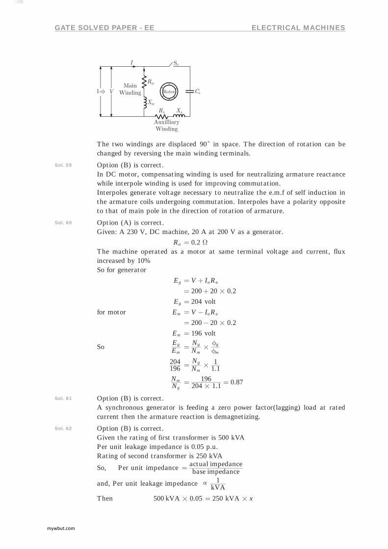
Sol. 58 Option (B) is correct.A single-phase capacitor start induction motor. It has cage rotor and its stator has two windings.
mywbut.com
GATE SOLVED PAPER - EE ELECTRICAL MACHINES
The two windings are displaced 90c in space. The direction of rotation can be changed by reversing the main winding terminals.
Sol. 59 Option (B) is correct.In DC motor, compensating winding is used for neutralizing armature reactance while interpole winding is used for improving commutation.Interpoles generate voltage necessary to neutralize the e.m.f of self induction in the armature coils undergoing commutation. Interpoles have a polarity opposite to that of main pole in the direction of rotation of armature.
Sol. 60 Option (A) is correct.Given: A 230 V, DC machine, 20 A at 200 V as a generator.
Ra .0 2 W=The machine operated as a motor at same terminal voltage and current, flux increased by 10%So for generator
Eg V I Ra a= + .200 20 0 2#= + Eg 204= volt
for motor Em V I Ra a= - .200 20 0 2#= - Em 196= volt
So EE
m
g NN
m
g
m
g# f
f=
196204 .N
N1 11
m
g#=
NN
g
m . .204 1 1196 0 87#
= =
Sol. 61 Option (B) is correct.A synchronous generator is feeding a zero power factor(lagging) load at rated current then the armature reaction is demagnetizing.
Sol. 62 Option (B) is correct.Given the rating of first transformer is 500 kVAPer unit leakage impedance is 0.05 p.u.Rating of second transformer is 250 kVA
So, Per unit impedance base impedanceactual impedance=
and, Per unit leakage impedance kVA1\
Then 500 kVA 0.05# 250 xkVA#=
mywbut.com

GATE SOLVED PAPER - EE ELECTRICAL MACHINES
x . .250500 0 05 0 1#= = p.u.
Sol. 63 Option (C) is correct.Given speed of a 4-pole induction motor is controlled by varying the supply frequency when the ratio of supply voltage and frequency is constant.
50f Hz= , 400V V= , 1440N rpm=So V f\
VV
2
1 ff2
1=
V2 400 2405030 V#= =
T fV S
2
\ c m
So SS
1
2 VV
ff
TT
2
12
1
2
1
2# #= b l
Given T1 T2=
Then S2 .0 04 240400
50302
# #= b l
S2 .0 066=
Nr (1 )N Ss= -
Nr Pf120=
So Nr .4120 30 1 0 066#= -^ h 840.6 rpm=
Sol. 64 Option (A) is correct.Given a 3-f induction motor
P 4= , 400V V= , 50f Hz= r1 1.0 W= , .r 0 52 W=l
X1 1.2 , 35X Xm2 W W= = =l
So, Speed of motor is
Ns 1500Pf120
4120 50 rpm#= = =
Torque Tst ( )N r r XV r
2180
s 1 22 2
22#p=
+ +ll
. ( . ) ( . )
.
2 3 14 1500180
1 5 2 43
400 0 5
2 2
2
# ##
#
=+
c m
63.58 Nm=
Sol. 65 Option (B) is correct.Given that 3-f induction motor star connected
P 10 kW= , 400V fV, Poles 4, 50 Hz= = =Full load current 20I AFl =
Efficiency inputoutput=
SoCu losses at full load
mywbut.com
GATE SOLVED PAPER - EE ELECTRICAL MACHINES
1520 762
2
#= b l .1354 67=
Total losses . .1354 67 1002 2356 67= + =
Efficiency .10000 2356 6710000 100#= + %81=
Sol. 66 Option (A) is correct.Given 3-f star connected synchronous motor
internal reactance 10 W=Operating at 50% load, unity power factor, 400 V, 5 kW
Excitation increased %1=So,full load current
IFl .3 400 15 10 7 22
3
# ##= =
E 2 ( ) ( )cos sinV I R V I Xa a a s2 2q q= - + -
So, E .3
400 10 3 62
2#= +c ^m h .2133 7289=
Excitation will increase 1% then E2
E2 . .2133 7289 0 01#= 236=
I Xa ( )E V22 2= - ( )236
34002
2= - c m .48 932=
Ia .10
48 932= .4 8932=
Load(%) .. . %7 22
4 8932 67 83= =
Sol. 67 Option (C) is correct.Given P 4= , 50f Hz=Slots 48= , each coil has 10 turnsShort pitched by an angle(a) to 36c electrical
Flux per pole 0.05 Wb=So,
Eph 4.44 Kf T Wphf=
Slot/Pole/ph 4 348 4#
= =
Slot/Pole 448 12= =
Slot angle 12180 15c= =
Kd ( / )( / )sin
sin4 15 2
4 15 2#= .0 957=
Kp cos 2a= .cos18 0 951c= =
In double layer wdg
No. of coil No of slots=
No. of turns/ph 348 10 160#= =
Then Eph . . . .4 44 0 025 50 0 957 0 951 160# # # # #=
808= V
mywbut.com

GATE SOLVED PAPER - EE ELECTRICAL MACHINES
EL 8083 #= EL 1400 V= (approximate)
Sol. 68 Option (A) is correct.line to line induced voltage, so in 2 phase winding
Slot/ pole/ph 6=
Tph 2480 240= =
Slot angle 1548180 4# c= =
Kd ( / )( / )
sinsin6 15 2
6 15 2#= 0.903=
Kp 236 0.951cos= =b l
Eph . . . .4 44 0 025 50 240 0 951 0 903# # # # #=
1143=
Sol. 69 Option (A) is correct.Fifth harmonic component of phase emf
So Angle 5180 36c= =
the phase emf of fifth harmonic is zero.
Sol. 70 Option (C) is correct.Given that: A 300 kVA transformerEfficiency at full load is 95% and 0.8 p.f. lagging 96% efficiency at half load and unity power factorSoFor Ist condition for full load
95% 0.80.8W WkVA
kVAcu i#
#= + + ...(1)
Second unity power factor half load
96% 0.50.5W WkVA
kVAcu i#
#= + + ...(2)
So W Wcu i+ .12 63= . .W W0 25 0 96cu i+ .6 25=Then Wcu .8 51= , .W 4 118i =
Sol. 71 Option (B) is correct.
Efficiency ( )h X W W X
XkVA
p.f. kVAi cu
2# #
# #=+ +
So X .4.118 .8 51 0 6956= =
%h . . . ( . )
.0 6956 300 4 118 8 51 0 6956
0 6956 1 3002
# ## #=
+ + h . %96 20=
Sol. 72 Option (D) is correct.The leakage reactances X1, and X2l are equal and magnetizing reactance Xm is higher than X1, and X2l
mywbut.com

GATE SOLVED PAPER - EE ELECTRICAL MACHINES
X1 X X<< m2. l
Sol. 73 Option (B) is correct.Three phase star delta connection of transformer induces a phase difference of 30c between output and input line voltage.
Sol. 74 Option (A) is correct.Given torque/speed curve of the induction motor
When the speed of the motor is in forward direction then slip varies from 0 to 1 but when speed of motor is in reverse direction or negative then slip is greater then 1. So at point W slip is greater than 1.
Sol. 75 Option (B) is correct.For an induction motor the ratio of gross power output to air-gap is equal to ( )s1 -
So airgap powergross power ( )s1= -
Sol. 76 Option (A) is correct.Given that two magnetic pole revolve around a stationary armature.At c1 the emf induced upward and no emf induced at c2 and c2l
Sol. 77 Option (B) is correct.Given A 50 kW DC shunt motor is loaded, thenat half the rated speed by armature voltage control
So P N\
Pnew 25250 kW= =
At 1.5 time the rated speed by field control
P constant=So P 50 kW=
Sol. 78 Option (C) is correct.In synchronous machine, when the armature terminal are shorted the field current should first be decreased to zero before started the alternator.In open circuit the synchronous machine runs at rated synchronous speed. The field current is gradually increased in steps.
mywbut.com

GATE SOLVED PAPER - EE ELECTRICAL MACHINES
The short circuit ratio is the ratio of field current required to produced the rated voltage on open to the rated armature current.
Sol. 79 Option (D) is correct.
In DC motor, E PN AZf= b l
or E K nwf=So armature emf E depends upon f and w only and torque developed depends
upon
T APZ I2
a
pf=
So, torque(T ) is depends of f and Ia and developed power(P ) is depend of flux f, speed w and armature current Ia .
Sol. 80 Option ( ) is correct.
Sol. 81 Option (B) is correct.Given a three-phase cage induction motor is started by direct on line switching at rated voltage. The starting current drawn is 6 time the full load current.
Full load slip %4=So
TT
Fl
Stb l I
I S2
Fl
StFl#= b l
( ) . .6 0 04 1 442#= =
Sol. 82 Option (B) is correct.Given single-phase induction motor driving a fan load, the resistance rotor is highSo
Eb V I Ra a= - ...(1)
Pmech E Ia a=
t Pm
mech
w= ...(2)
From equation (1) and (2) the high resistance of rotor then the motor achieves
quick acceleration and torque of starting is increase.
Sol. 83 Option (A) is correct.Given /V f control of induction motor, the maximum developed torque remains same
we have, E 4.44K f Tw 11 f=If the stator voltage drop is neglected the terminal voltage E1. To avoid saturation and to minimize losses motor is operated at rated airgap flux by varying terminal voltage with frequency. So as to maintain ( / )V f ratio constant at the rated value, the magnetic flux is maintained almost constant at the rated value which keeps maximum torque constant.
Sol. 84 Option (B) is correct.
Given P 1000 kVA= , 6.6 kVReactance 20 W= and neglecting the armature resistance at full load and unity power factor
So P V I3 L L=
mywbut.com

GATE SOLVED PAPER - EE ELECTRICAL MACHINES
I .
.3 6 61000 87 47#
= = A
So, IX . .87 47 20 1 75#= = kV
Eph2 . ( . )
36 5 1 75
22= +c m
Eph . ( . )3
6 5 1 752
2= +c m
Eph 4.2 kV=
EL E3 ph= a Star connection
EL . .1 732 4 2#= 7.26 kV=
Sol. 85 Option (C) is correct.
Torque angle za tan RX
a
s1= -b l
za ..tan 6 6
3 1 751 #= -c m .24 6c=
Sol. 86 Option (B) is correct.Given thatTransformer rating is 500 kVA
Iron losses 300= W
full load copper losses 600= W
Maximum efficiency condition
Wi X Wc2=
So, X WW
c
i= 600300= 0.707=
efficiency% .0 707 100#= . %70 7=
Sol. 87 Option (C) is correct.Stepper motor is rotated in steps, when the supply is connected then the torque is produced in it. The higher value of torque is pull out torque and less torque when the torque is pull in torque.
Sol. 88 Option (C) is correct.The stepper motor has the permanent magnet rotor and stator has made of windings, it’s connected to the supply.
mywbut.com
GATE SOLVED PAPER - EE ELECTRICAL MACHINES
Sol. 89 Option (D) is correct.1-phase induction motor is not self starting, so it’s used to start different method at full load condition, capacitor-run type motor have higher power factor. In this type the capacitor is connected in running condition.
Sol. 90 Option (C) is correct.Given that if 3-f induction motor is rotated in clockwise then the phase sequence of supply voltage is A-B-C. In counter clock wise rotation of the motor the phase sequence is change so in the counter clockwise rotation the phase sequence is A-C-B.
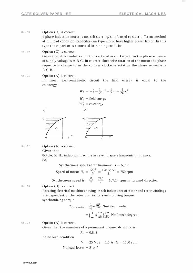
Sol. 91 Option (A) is correct.In linear electromagnetic circuit the field energy is equal to theco-energy.
Wf W Li L21
21
21'
f i2 2y y= = = =
Wf field energy= W '
f co energy=
Sol. 92 Option (A) is correct.Given that8-Pole, 50 Hz induction machine in seventh space harmonic mmf wave.So,
Synchronous speed at 7th harmonic is /7Ns=
Speed of motor Ns Pf120= 7508
120 50 rpm#= =
Synchronous speed is N7 7
750s= = 107.14 rpm= in forward direction
Sol. 93 Option (B) is correct.Rotating electrical machines having its self inductance of stator and rotor windings is independent of the rotor position of synchronizing torque.synchronizing torque
Tsynchronizing m ddP1
sw d= Nm/elect. radian
m ddP P1
180sw dp= b l Nm/mech.degree
Sol. 94 Option (A) is correct.Given that the armature of a permanent magnet dc motor is
Ra 0.8W=At no load condition
V 25 V= , 1.5I A= , 1500N rpm= No load losses E I#=
mywbut.com

GATE SOLVED PAPER - EE ELECTRICAL MACHINES
a E V IRa= -So no load losses ( . . ) .25 1 5 0 8 1 5#= - 5.73 W=At load condition I 3.5 A= Iron losses I R2= ( . ) .3 5 0 82
#= 9.8 W= Total losses No load losses iron losses+= 5.7 9.83= + 5.54 W= Total power P VI= P .25 3 5#= P .87 5= W
Efficiency inputoutput=
h total powertotal power losses= - .
. . 10087 587 5 45 5
#= -
. %48 0=
Sol. 95 Option (D) is correct.Given that 50 kVA, 3300/230 V, 1-f transform
Vin 3300 V= Vout 3300 230 3530 V= + =Output current I2 and output voltage 230 VSo
I2 217.423050 10 A
3#= =
When the output voltage is Vout then kVA rating of auto transformer will be
I2 .3530 217 4#= .767 42= kVA
Sol. 96 Option (D) is correct.Given that 100 kVA, 11000/400 V, Delta-star distribution transformer resistance is 0.02 pu and reactance is 0.07 pu
So pu impedance Zpu . .j0 02 0 07= +Base impedance referred to primary
ZBase /( )
3630V I
V3
3100 1011 10
L L
P2
3
3 2
#
# W= = =
The phase impedance referred to primary
Zprimary Z Zpu Base#= ( . . )( )j0 02 0 07 3630= + . .j72 6 254 1= +
Sol. 97 Option (A) is correct.Given that230 V, 50 Hz, 4-Pole, capacitor-start induction motor
mywbut.com

GATE SOLVED PAPER - EE ELECTRICAL MACHINES
Zm R Xm m= + . .j6 0 4 0 W= + ZA R XA A= + . .j8 0 6 0 W= +Phase angle of main winding
Im+ Zm+= - (6 4)j+=- + .33 7c+=-So angle of the auxiliary winding when the capacitor is in series.
IA+ (8 6)j j C1+ w=- + + (8 6)j C
j+ w= + -
a I IA m+ += -
So 90 ( . )tan C8
6 133 71 w=-
-- -- f p> H
C1
w 18= w f2p=
So C .f18 21
18 2 3 14 501
# # # #p= =
176.8 Fm=
Sol. 98 Option (A) is correct.Given that the armature has per phase synchronous reactance of1.7 W and two alternator is connected in parallelSo,
both alternator voltage are in phaseSo,
Ef1 3300
3=
Ef2 3
3200=
Synchronizing current or circulating current
T TE
S S
C
1 2= +
Reactance of both alternator are same
So T TE E
S S
f f
1 2
1 2= +-
. .31
1 7 1 73300 3200= +
-b l .16 98= A
Sol. 99 Option (C) is correct.Given 400 4V PV,15 kW power and= = f 50 Hz= , Full load slip (S ) %4=
mywbut.com
GATE SOLVED PAPER - EE ELECTRICAL MACHINES
So Ns Pf120= 4
120 50 1500#= = rpm
Actual speed synchronous speed slip= -
N 1500 1004 1500#= - 1440= rpm
Torque developed T ( )S
P1sw
= - , where ( )S1sw - 2 N60p=
2 144015 10 603
## #p= .99 47= Nm
Sol. 100 Option (B) is correct.Given .1 8c angle, 2-f Bipolar stepper motor and stepping rate is100 step/secondSo step required for one revolution
. 2001 8360 steps= =
a Time required for one revolution 2= seconds
rev/sec 0.5 rps=and rev/min 30= rpm
Sol. 101 Option (C) is correct.Given that:P 8= Pole, DC generator has wave-wound armature containing 32 coil of 6 turns each. Simplex wave wound flux per pole is 0.06 Wb
N 250 rpm=So induced armature voltage
Eg 60AZNPf=
Z total no.of armature conductor= 2 2 32 6 384CNC # #= = =
Eg . .
60 20 06 250 3 84 8
## # #=
2Aa = for wave winding
Eg 384= volt
Sol. 102 Option (C) is correct.Given a 400 V, 50 Hz and 0.8 p.f. loading delta connection 50 Hz synchronous machine, the reactance is 2 W. The friction and windage losses are 2 kW and core losses is 0.8 kW and shaft is supply 9 kW at a 0.8 loading power factorSo
Input power 9 kW 2 kW 0.8 kW= + + 11.8 kW=
a Input power V I3 2 2= 11.8 kW=
I2 .
11.83 400 0 8
kW# #
= 21.29= A
Sol. 103 Option (B) is correct.Given that 500 MW, 3-f star connected synchronous generator has a rated voltage of 21.5 kV and 0.85 Power factor
So V I3 L L 500= MW
IL . .3 21 5 10 0 85
500 103
6
# # ##= 15.79 103
#=
IL .15 79= kA
mywbut.com

GATE SOLVED PAPER - EE ELECTRICAL MACHINES
Sol. 104 Option (D) is correct.Given that 1-f transformer, maximum efficiency 90% at full load and unity power factor
So h coscos
V I P PV I
i c2 2 2
2 2 2
ff= + +
( . )( . )cos
cosL F P P
L Fc2
2
i(Pu)ff= + +
where . .L F is the load fator.
At full load, load factor is
. .L F 1PP
c
i= =
cos 2f 1= at unity power factor
so, 90% P1 21 1
i
#= +
Pi .0 0555= MVA
At half load, load factor is
L.F .21 5= =
So, h . . ( . ) .
.0 5 0 0555 0 5 0 0555
0 5 1 1002# #
# #=+
. %87 8=
Sol. 105 Option (C) is correct.In food mixer the universal motor is used and in cassette tap recorder permanent magnet DC motor is used. The Domestic water pump used the single and three phase induction motor and escalator used the three phase induction motor.
Sol. 106 Option (D) is correct.Given a engine drive synchronous generator is feeding a partly inductive load. A capacitor is connected across the load to completely nullify the inductive current. Then the motor field current has to be reduced and fuel input left unaltered.
Sol. 107 Option (A) is correct.
Given open circuit and full-load zero power factor of a synchronous generator. At point Q the zero power factor at 1.0 pu voltage. The voltage drop at point PQ is across synchronous reactance.
Sol. 108 Option (D) is correct.Given no load test on 3-f induction motor, the graph between the input power and voltage drop is shown in figure, the intersection point yield the friction and windage loss.
mywbut.com

GATE SOLVED PAPER - EE ELECTRICAL MACHINES
Sol. 109 Option ( ) is correct.
Sol. 110 Option (C) is correct.
Given that: The armature resistance in per unit is 0.2
so, Ra .0 2=back emf equation of motor is
Eb V I Ra a= -given that no mechanical losses and armature reaction is neglected, so per unit value of emf induced by motor is
Eb .0 98=The DC shunt motor is mechanically coupled by the generator so the emf
induced by motor and generator is equal
Eg Eb=so voltage generated by the generator is
V . . .0 98 1 0 2 0 96#= - =per unit value of load resistance is equal to 0.96
Sol. 111 Option (D) is correct.Given that when the switch S1 is closed and S2 is open then the 11000 V is step down at 415 V outputSecond time when the switch S1 is open and switch S2 is closed then 2-phase supply is connected to the transformer then the ratio of voltage is
VV
2
1 26.50NN
41511000
2
1= = =
The output terminal a and c are in opposite phase so cancelled with each other and terminal is equal to zero volt.
Sol. 112 Option (D) is correct.Given that
N1: :N N2 3 is : :4 2 1
Resistance R 10 W= V1 400 V=
So VV
2
1 NN
24
2
1= =
V2 V4
2 1= 200 V=
mywbut.com

GATE SOLVED PAPER - EE ELECTRICAL MACHINES
and VV
3
1 NN
14
3
1= =
V3 100 V=so current in secondary winding
I2 RV
102002= = 20 A=
The current in third winding when the capacitor is connected
so I3 .jXV
j j2 5100 40
c
3= - = - =
When the secondary winding current I2 is referred to primary side i.e I '1
So II '
2
1 NN
42
1
2= =
I '1
20 102 A= =
and winding third current I3 is referred to Primary side i.e I ''1. I3 flows to opposite
to I1
So II ''
3
1
- NN
41
1
3= =
I ''1 j10=-
So total current in primary winding is
I1 I I'' ''1 2= + 10 10j A= -
Sol. 113 Option (A) is correct.Given that:P Stator winding current is dc, rotor winding current is ac
Q Stator winding current is ac, rotor winding current is dc
R Stator winding current is ac, rotor winding current is ac
S Stator has salient pole and rotor has commutator
T Rotor has salient pole and slip rings and stator is cylindrical
U Both stator and rotor have poly-phase windings
SoDC motor/machines:The stator winding is connected to dc supply and rotor winding flows ac current. Stator is made of salient pole and Commutator is connected to the rotor so rotor winding is supply ac power.
Induction machines:In induction motor the ac supply is connected to stator winding and rotor and stator are made of poly-phase windings.
Synchronous machines:In this type machines the stator is connected to ac supply but rotor winding is excited by dc supply. The rotor is made of both salient pole and slip rings and stator is made of cylindrical.
Sol. 114 Option (C) is correct.Given thatFs is the peak value of stator mmf axis. Fr is the peak value of rotor mmf axis. The rotor mmf lags stator mmf by space angled. The direction of torque acting on the rotor is clockwise or counter clockwise.
mywbut.com

GATE SOLVED PAPER - EE ELECTRICAL MACHINES
When the opposite pole is produced in same half portion of stator and rotor then the rotor moves. So portion of stator is north-pole in ABC and rotor abc is produced south pole as well as portion surface CDA is produced south pole and the rotor cda is produced North pole.The torque direction of the rotor is clock wise and torque at surface is in counter clockwise direction.
Sol. 115 Option (A) is correct.Given that:A 4-pole, 3-f, double layer winding has 36 slots stator with 60c phase spread, coil span is 7 short pitchedso,
Pole pitch poleslot= 4
36 9= =
Slot/pole/phase 3=so, 3-slots in one phase, if it is chorded by 2 slots then
Out of 3 2" have different phase
Out of 36 24" have different phase.
Sol. 116 Option (B) is correct.Given that:3-f induction motor is driving a constant load torque at rated voltage and frequency. Voltage and frequency are halved and stator resistance, leakage reactance and core losses are ignored.Then the motor synchronous speed and actual speed difference are same.
Ns Pf120=
The leakage reactance are ignored then the air gap flux remains same and the stator resistance are ignored then the stator current remain same.
Sol. 117 Option (D) is correct.Given that: 1-f induction motor main winding excited then the rotating field of motor changes, the forward rotating field of motor is greater then the back ward rotating field.
Sol. 118 Option (B) is correct.Given that:A dc series motor driving a constant power load running at rated speed and rated voltage. It’s speed brought down 0.25 pu. ThenEmf equation of dc series motor
E ( )V R Ra se= - + R Ra se+ R=so, E V IR= - K Nf=
then N KEf=
In series motor Ifa
so, N KIV IR= -
At constant power load
E I# T W Const#= = ...(1)
mywbut.com

GATE SOLVED PAPER - EE ELECTRICAL MACHINES
T K I KI 2f= = ...(2)If W is decreased then torque increases to maintain power constant.
T I 2\
W 41= then T 4=
So current is increased 2 time and voltage brought down to 0.5 pu.
***********
mywbut.com