YCWL 50 Hz Style A Water Cooled Liquid Cooled...
60
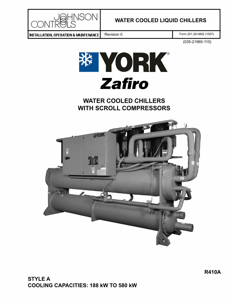
INSTALLATION, OPERATION & MAINTENANCE WATER COOLED LIQUID CHILLERS Revision 0 Form 201.26-NM2 (1007) (035-21965-110) Zafiro R410A STYLE A COOLING CAPACITIES: 188 kW TO 580 kW WATER COOLED CHILLERS WITH SCROLL COMPRESSORS
Transcript of YCWL 50 Hz Style A Water Cooled Liquid Cooled...
INSTALLATION, OPERATION & MAIN TE NANCE
WATER COOLED LIQUID CHILLERS
Revision 0 Form 201.26-NM2 (1007)
(035-21965-110)
Zafi ro
R410ASTYLE ACOOLING CAPACITIES: 188 kW TO 580 kW
WATER COOLED CHILLERSWITH SCROLL COMPRESSORS
2 035-21965-110 Rev. 0
FORM 201.26-NM2 (1007)
This equipment is a relatively complicated ap pa ra tus. Dur ing installation, operation, maintenance or service, in di vid u als may be exposed to certain com po nents or conditions in clud ing, but not limited to: re frig er ants, oils, materials un der pressure, rotating com po nents, and lethal voltage. Each of these items has the po ten tial, if misused or handled im prop er ly, to cause bodi ly injury or death. It is the obligation and re spon si bil i ty of operating/service per son nel to iden ti fy and rec og nize these inherent hazards, protect them selves, and pro ceed safely in completing their tasks. Failure to com ply with any of these requirements could re sult in se ri ous dam age to the equipment and the prop er ty in which it is sit u at ed,
IMPORTANT!Read BEFORE PROCEEDING!
GENERAL SAFETY GUIDELINES
as well as severe personal injury or death to them selves and people at the site.
This document is intended for use by owner-authorized operating/service personnel. It is expected that this in di vid u al possesses independent training that will en able them to perform their assigned tasks properly and safe ly. It is essential that, prior to performing any task on this equipment, this individual shall have read and un der stood this document and any referenced materials. This in di vid u al shall also be familiar with and comply with all ap pli ca ble governmental standards and regulations per tain ing to the task in question.
SAFETY SYMBOLSThe following symbols are used in this document to alert the reader to areas of potential hazard:
CAUTION identi es a hazard which could lead to damage to the ma chine, damage to other equip ment and/or en vi ron men tal pollution. Usually an in struc tion will be given, together with a brief ex pla na tion.
NOTE is used to highlight ad di tion al information which may be helpful to you.
DANGER indicates an im mi nent ly hazardous situation which, if not avoid ed, will re sult in death or se ri ous injury.
DANGER
WARNING indicates a potentially haz ard ous sit u a tion which, if not avoid ed, could result in death or se ri ous in ju ry.
External wiring, unless speci ed as an optional connection in the man u fac tur er’s prod uct line, is not to be connected inside the micro pan el cab i net. De vic es such as re lays, switch es, transducers and controls may not be installed inside the pan el. No external wiring is al lowed to be run through the micro panel. All wir ing must be in ac cor dance with Johnson Controls pub lished spec i ca tions and must be per formed only by qual i ed Johnson Controls personnel. Johnson Controls will not be re spon si ble for dam ag es/problems re sult ing from im prop er con nec tions to the con trols or ap pli ca tion of im prop er con trol sig nals. Failure to fol low this will void the man u fac tur er’s warranty and cause serious dam age to property or injury to per sons.
3
FORM 201.26-NM2 (1007)
035-21965-110 Rev. 0
CHANGEABILITY OF THIS DOCUMENT
In complying with Johnson Controls policy for continuous product improvement, the in for ma tion con tained in this document is subject to change without notice. While Johnson Controls makes no com mit ment to update or provide current information au to mat i cal ly to the manual owner, that information, if ap pli ca ble, can be ob tained by con tact ing the nearest Johnson Controls Service Centre.
It is the responsibility of operating/service personnel to verify the ap pli ca bil i ty of these documents to the equipment in question. If there is any question in the mind of operating/service personnel as to the applicability of these doc u ments, then prior to work ing on the equipment, they should verify with the owner whether the equip ment has been modifi ed and if current literature is available.
4 035-21965-110 Rev. 0
FORM 201.26-NM2 (1007)
TABLE OF CONTENTS
GENERAL SAFETY GUIDELINES ....................... 2SAFETY SYMBOLS ................................................ 2CHANGEABILITY OF THIS DOCUMENT .......... 3TABLE OF CONTENTS .......................................... 4
1 GENERAL CHILLER INFORMATION & SAFETY
INTRODUCTION ............................................... 6WARRANTY ....................................................... 6SAFETY .............................................................. 6Standards for Safety ............................................. 6FLUORINATED GREENHOUSE GASES ........ 7RESPONSIBILITY FOR SAFETY ..................... 7ABOUT THIS MANUAL ................................... 7MISUSE OF EQUIPMENT ................................. 8Suitability for Application ................................... 8Structural Support ................................................ 8Mechanical Strength ........................................... 8General Access ..................................................... 8Pressure Systems ................................................. 8Electrical .............................................................. 8Refrigerants and Oils ........................................... 8High Temperature and Pressure Cleaning............ 8Emergency Shutdown .......................................... 8Safety Labels........................................................ 9MATERIAL SAFETY DATA ............................ 10
2 PRODUCT DESCRIPTION
Introduction ........................................................ 15Compressors ...................................................... 15Refrigerant Circuits ........................................... 16Evaporator .......................................................... 16Condenser .......................................................... 16Power and Control Panels .................................. 16OPTIONS AND ACCESSORIESAlarm Contacts: ................................................ 17Soft Starters ....................................................... 18Power Factor Correction .................................... 18Language LCD and Keypad .............................. 18Non-reversible Heat Pump................................. 1838 mm Evaporator Insulation ............................ 18Pressure Relief (CE/PED) Service Valve Kit .... 18Dual Pressure Relief Valves ............................... 18
Suction Service Valves ....................................... 18Victaulic Flange Kit ........................................... 18Compressor Acoustic Blankets .......................... 18Final overspray .................................................. 18Flow switch ........................................................ 18Differential Pressure Switch .............................. 18Neoprene Pad Isolators ...................................... 1825 mm Spring Isolators ...................................... 18UNIT MODEL NUMBER NOMENCLATURENOMENCLATURE ........................................... 20
3 HANDLING AND STORAGE
DELIVERY AND STORAGE ........................... 21INSPECTION .................................................... 21MOVING THE CHILLER ................................ 21Lifting by Crane/Hoist ....................................... 21Lifting by Fork lift ............................................. 21LIFTING WEIGHTS ......................................... 21
4 INSTALLATION
Location Requirements ...................................... 23Installation of Vibration Isolators ...................... 23Pipework Connection ......................................... 23Water Treatment ................................................. 24Chilled Liquid System ....................................... 24Connection Types & Sizes ................................. 25Refrigerant Relief Valve Piping ......................... 25Condenser Cooling Liquid Systems .................. 26Inlet Temperature Control (by others) ............... 26ELECTRICAL CONNECTION ........................ 27Power Wiring ..................................................... 27Single Point Power Supply Wiring .................... 27Remote Emergency Stop Device ....................... 27Control Wiring - Voltage Free Contacts ............. 27Chilled Liquid Pump Starter .............................. 27Run Contacts ...................................................... 28Alarm Contacts .................................................. 28Control Wiring - System Inputs ......................... 28Flow Switch ....................................................... 28Remote Start/Stop .............................................. 28Remote Reset of Chilled Liquid Setpoint .......... 28Remote Load Limiting ....................................... 28Heat Pump Kit ................................................... 28EMS Analogue Input ......................................... 28BACnet ............................................................. 28CONNECTION DIAGRAM ............................. 29

5
FORM 201.26-NM2 (1007)
035-21965-110 Rev. 0
5 COMMISSIONING
PREPARATION ................................................. 31Preparation - Power Off ..................................... 31Soft Start (Option) ............................................. 32FIRST TIME START-UP ................................... 33
6 TECHNICAL DATA
EVAPORATOR WATER PRESSURE DROP .......OPERATING LIMITATIONS ........................... 36PHYSICAL DATA ............................................. 37ELECTRICAL DATA - YCWL/SE MODELS .. 38COMPRESSOR DATA ...................................... 38ELECTRICAL DATA - YCWL/HE MODELS . 39COMPRESSOR DATA ...................................... 39DIMENSIONS - YCWL0240SE, YCWL0290SE, YCWL0345SE, YCWL0395SE,YCWL0200HE, YCWL0230HE, YCWL0260HE, YCWL0300HE, YCWL0345HE YCWL0425HE ........................ 40DIMENSIONS - YCWL0385HE, YCWL0445HE, YCWL0530HE AND YCWL0610HE ............... 42WEIGHT DISTRIBUTION & VIBRATION ISOLATOR DATA ............................................. 44
7 UNIT OPERATION
GENERAL DESCRIPTION .............................. 49START-UP ......................................................... 49NORMAL RUNNING AND CYCLING........... 49SHUTDOWN .................................................... 49
8 MAINTENANCE
GENERAL REQUIREMENTS ......................... 51DAILY MAINTENANCE ................................. 51SCHEDULED MAINTENANCE ..................... 51Evaporator/Condenser In-Service Inspection .... 52
9 TROUBLE SHOOTING
COMPETENT PERSONS TROUBLE SHOOT-ING GUIDE ....................................................... 53SENSOR CALIBRATION CHARTS ................ 55Leaving Liquid Temperature (-BLLT) ............... 55Discharge Pressure (-BDP) and Suction (-BSP) Transducers ........................................................ 55
10 SPARE PARTS
RECOMMENDED SPARES ............................. 57RECOMMENDED COMPRESSOR OIL ......... 57ASSOCIATED DRAWINGS ............................. 57
11 DECOMMISSIONING. DISMANTLING AND DISPOSAL 55
GENERAL ......................................................... 59
6 035-21965-110 Rev. 0
FORM 201.26-NM2 (1007)
INTRODUCTION
YORK YCWL chillers are manufactured to the highest design and construction standards to ensure high performance, reliability and adaptability to all types of air conditioning installations.
The unit is intended for cooling water or glycol solutions and is not suitable for purposes other than those specifi ed in this manual.
This manual contains all the information required for correct installation and commissioning of the unit, together with operating and maintenance instructions. The manuals should be read thoroughly before attempting to operate or service the unit.
All procedures detailed in the manuals, including installation, commissioning and maintenance tasks must only be performed by suitably trained and qualifi ed personnel.
The manufacturer will not be liable for any injury or damage caused by incorrect installation, commissioning, operation or maintenance resulting from a failure to follow the procedures and instructions detailed in the manuals.
WARRANTY
Johnson Controls warrants all equipment and materials against defects in workmanship and materials for a period of eighteen months from date of shipment, unless labor or extended warranty has been purchased as part of the contract.
The warranty is limited to parts only replacement and shipping of any faulty part, or sub-assembly, which has failed due to poor quality or manufacturing errors. All claims must be supported by evidence that the failure has occurred within the warranty period, and that the unit has been operated within the designed parameters specifi ed.
All warranty claims must specify the unit model, serial number, order number and run hours/starts. Model and serial number information is printed on the unit identifi cation plate.
The unit warranty will be void if any modifi cation to the unit is carried out without prior written approval from Johnson Controls.
GENERAL CHILLER INFORMATION & SAFETY
For warranty purposes, the following conditions must be satisfi ed:
The initial start of the unit must be carried out by trained personnel from an Authorized Johnson Controls Service Centre. See Section 5, Commissioning.
Only genuine Johnson Controls approved spare parts, oils, coolants, and refrigerants must be used. Recommendations on spare parts stocking can be found in Section 7, Maintenance.
All the scheduled maintenance operations detailed in this manual must be performed at the specifi ed times by suitably trained and qualifi ed personnel. See Section 7, Maintenance,
Failure to satisfy any of these conditions will automatically void the warranty. See Warranty Policy (Section 7, Maintenance).
SAFETY
Standards for Safety
YCWL chillers are designed and built within an EN ISO 9002 accredited manufacturing organisation.
Chillers conform with the following European Directives:
Machinery Directive (98/37/EC)
Low Voltage Directive (73/23/EEC, EN 60204)
EMC Directive (89/336/EEC)
Pressure Equipment Directive (97/23/EC)
Or conversely comply with the applicable sections of the following Standards and Codes:
ANSI/ASHRAE Standard 15 - Safety Code for Mechanical Refrigeration.
ASHRAE 90.1 - Energy Effi ciency Compliance.
ANSI/NFPA Standard 70 - National Electrical Code (N.E.C.).
ASME Boiler and Pressure Vessel Code, Section VIII Division 1.
ASHRAE 34 - Number Designation and Safety Classifi cation of Refrigerants.
•
•
•
•
•
•
•
•
•
•
•
•
•
7
FORM 201.26-NM2 (1007)
035-21965-110 Rev. 0
ARI Standard 550/590 - Positive Displacement Compressors and Water Cooled Rotary Sdrew Water Chilling Packages.
Conform to UL code 1995 for construction of chillers and provide ETL/cETL listing label.
OSHA - Occupied Safety and Health Act.
ARI 370 Sound Rating of Large Outdoor Refrigeration and Air Conditioning Equipment.
FLUORINATED GREENHOUSE GASES
This equipment contains fl uorinated greenhouse gases covered by the Kyoto Protocol.
The global warming potential of the refrigerant (R410A) used in this unit is 1720.
The refrigerant quantity is stated in the Physical Data table in Section 9 of this document.
The fl uorinated greenhouse gases in this equipment may not be vented to the atmosphere.
This equipment should only be serviced by qualifi ed technicians.
RESPONSIBILITY FOR SAFETY
Every care has been taken in the design and manufacture of the unit to ensure compliance with the safety requirements listed above. However, the individual operating or working on any machinery is primarily responsible for:
Personal safety, safety of other personnel, and the machinery.
Correct utilization of the machinery in accordance with the procedures detailed in the manuals.
•
•
•
•
•
•
•
•
•
•
•
•
ABOUT THIS MANUAL
The following terms are used in this document to alert the reader to areas of potential hazard.
A WARNING is given in this document to identify a hazard, which could lead to personal injury. Usually an instruction will be given, together with a brief explanation and the possible result of ignoring the instruction.
A CAUTION identi es a hazard which could lead to damage to the machine, damage to other equipment and/or environmental pollution. Usually an instruction will be given, together with a brief explanation and the possible result of ignoring the instruction.
A NOTE is used to highlight additional information, which may be helpful to you but where there are no special safety implications.
The contents of this manual include suggested best working practices and procedures. These are issued for guidance only, and they do not take precedence over the above stated individual responsibility and/or local safety regulations.
This manual and any other document supplied with the unit are the property of Johnson Controls which reserves all rights. They may not be reproduced, in whole or in part, without prior written authorization from an authorized Johnson Controls representative.
1
8 035-21965-110 Rev. 0
FORM 201.26-NM2 (1007)
MISUSE OF EQUIPMENT
Suitability for Application
The unit is intended for cooling water or glycol solutions and is not suitable for purposes other than those specifi ed in these instructions. Any use of the equipment other than its intended use, or operation of the equipment contrary to the relevant procedures may result in injury to the operator, or damage to the equipment.
The unit must not be operated outside the design parameters specifi ed in this manual.
Structural Support
Structural support of the unit must be provided as indicated in these instructions. Failure to provide proper support may result in injury to the operator, or damage to the equipment and/or building.
Mechanical Strength
The unit is not designed to withstand loads or stresses from adjacent equipment, pipework or structures. Additional components must not be mounted on the unit. Any such extraneous loads may cause structural failure and may result in injury to the operator, or damage to the equipment.
General Access
There are a number of areas and features, which may be a hazard and potentially cause injury when working on the unit unless suitable safety precautions are taken. It is important to ensure access to the unit is restricted to suitably qualifi ed persons who are familiar with the potential hazards and precautions necessary for safe operation and maintenance of equipment containing high temperatures, pressures and voltages.
Pressure Systems
The unit contains refrigerant vapor and liquid under pressure, release of which can be a danger and cause injury. The user should ensure that care is taken during installation, operation and maintenance to avoid damage to the pressure system. No attempt should be made to gain access to the component parts of the pressure system other than by suitably trained and qualifi ed personnel.
Electrical
The unit must be earthed. No installation or maintenance work should be attempted on the electrical equipment without fi rst switching power OFF, isolating and locking-off the power supply. Servicing and maintenance on live equipment must only be performed by suitably trained and qualifi ed personnel. No attempt should be made to gain access to the control panel or electrical enclosures during normal operation of the unit.
Refrigerants and Oils
Refrigerants and oils used in the unit are generally nontoxic, non-fl ammable and non-corrosive, and pose no special safety hazards. Use of gloves and safety glasses is, however, recommended when working on the unit. The build up of refrigerant vapor, from a leak for example, does pose a risk of asphyxiation in confi ned or enclosed spaces and attention should be given to good ventilation.
High Temperature and Pressure Cleaning
High temperature and pressure cleaning methods (e.g. steam cleaning) should not be used on any part of the pressure system as this may cause operation of the pressure relief device(s). Detergents and solvents, which may cause corrosion, should also be avoided.
Emergency Shutdown
In case of emergency, the control panel is fi tted with a incoming supply non-fused disconnect switch which can be used as the emergency stop device. When operated it removes the electrical supply to the control circuit thus shutting down the unit.
9
FORM 201.26-NM2 (1007)
035-21965-110 Rev. 0
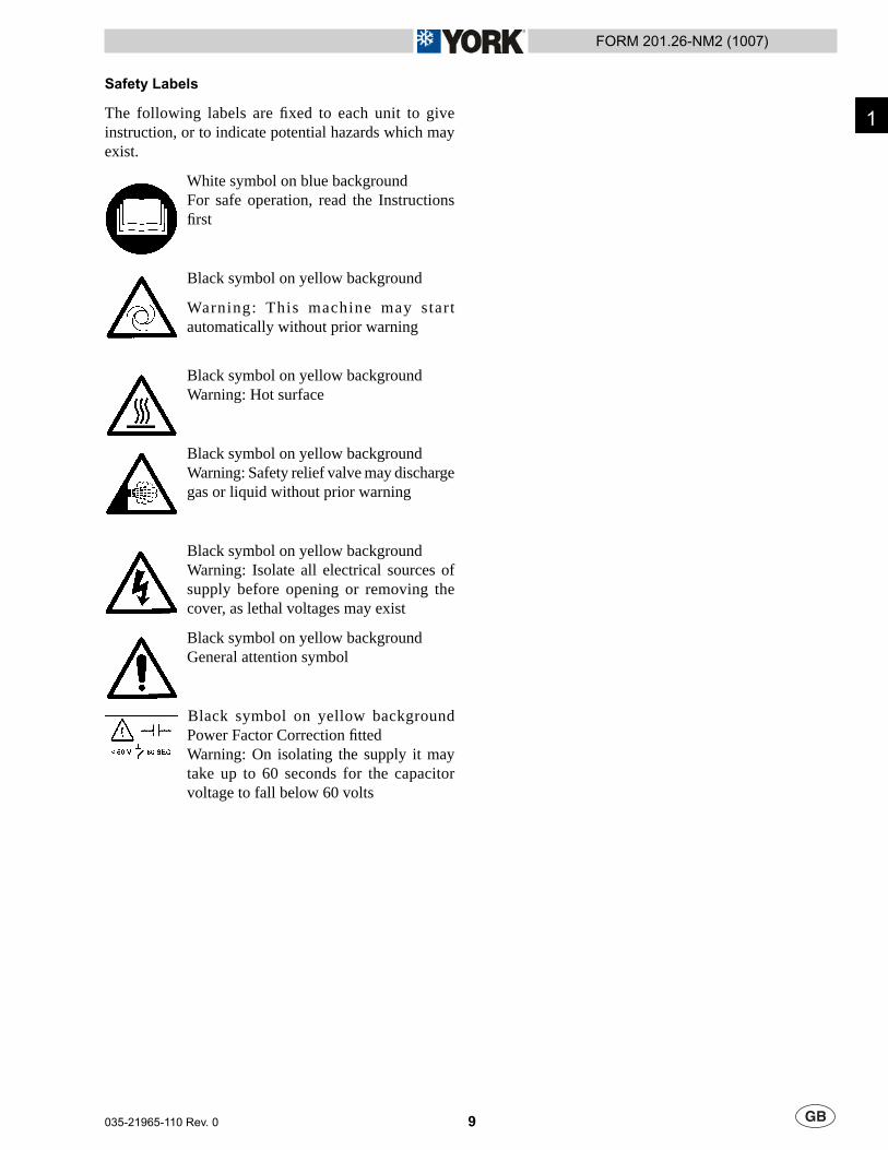
Safety Labels
The following labels are fi xed to each unit to give instruction, or to indicate potential hazards which may exist.
White symbol on blue backgroundFor safe operation, read the Instructions fi rst
Black symbol on yellow background
Warning: This machine may start automatically without prior warning
Black symbol on yellow backgroundWarning: Hot surface
Black symbol on yellow backgroundWarning: Safety relief valve may discharge gas or liquid without prior warning
Black symbol on yellow backgroundWarning: Isolate all electrical sources of supply before opening or removing the cover, as lethal voltages may exist
Black symbol on yellow backgroundGeneral attention symbol
Black symbol on yellow backgroundPower Factor Correction fi ttedWarning: On isolating the supply it may take up to 60 seconds for the capacitor voltage to fall below 60 volts
1

10 035-21965-110 Rev. 0
FORM 201.26-NM2 (1007)
MATERIAL SAFETY DATA
Components Material PENTAFLUOROETHANE (HFC-125) DIFLUOROMETHANE (HFC-32)CAS Number 354-33-6 75-10-5% 50 50
Inhalation of high concentrations of vapour is harmful and may cause heart irregularities, unconsciousness, or death. Intentional misuse or deliberate inhalation may cause death without warning. Vapour reduces oxygen available for breathing and is heavier than air. Liquid contact can cause frostbite.At flame temperatures, this material can decompose to hydrogen fluoride which can be lethal at much lower concentrations.Overexposure to the vapours by inhalation may include temporary nervous system depression with anaesthetic effects such as dizziness, headache, confusion, incoordination, and loss of consciousness. Higher exposures to the vapours may cause temporary alteration of the heart's electrical activity with irregular pulse, palpitations, or inadequate circulation. Gross overexposure may be fatal. Skin contact with the liquid may cause frostbite.
Individuals with preexisting diseases of the central nervous or cardiovascular system may have increased susceptibility to the toxicity of increased exposures.
Carcinogenicity Information None of the components present in this material at concentrations equal to or greater than 0.1% are listed by IARC, NTP, OSHA or ACGIH as a carcinogen.
If inhaled, immediately remove to fresh air. Keep person calm.If not breathing, give artificial respiration. If breathing is difficult, give oxygen. Call a physician.
Skin Contact Flush area with lukewarm water. Do not use hot water. If frostbite has occurred, call a physician.
Eye Contact In case of contact, immediately flush eyes with plenty of water for at least 15 minutes. Call a physician.
Ingestion Do not induce vomiting. Give plenty of water in sipsNotes to Physicians THIS MATERIAL MAY MAKE THE HEART MORE SUSCEPTIBLE TO ARRHYTHMIAS.
Catecholamines such as adrenaline, and other compounds having similar effects, should be reserved for emergencies and then used only with special caution.
Flash Point : No flash pointFlammable Limits in Air, % by Volume:LEL : None per ASTM E681UEL : None per ASTM E681Autoignition: Not determinedCylinders may rupture under fire conditions. Decomposition may occur.Contact of welding or soldering torch flame with high concentrations of refrigerant can result in visible changes in the size and colour of torch flames. This flame effect will only occur in concentrations of product well above the recommended exposure limit, therefore stop all work and ventilate to disperse refrigerant vapours from the work area before using any open flames.R-410A is not flammable in air at temperatures up to 100 deg C (212 deg F) at atmospheric pressure. However, mixtures of R-410A with high concentrations of air at elevated pressure and/or temperature can become combustible in the presence of an ignition source. R-410A can also become combustible in an oxygen enriched environment (oxygen concentrations greater than that in air). Whether a mixture containing R-410A and air, or R-410A in an oxygen enriched atmosphere becomes combustible depends on the inter-relationship of 1) the temperature 2) the pressure, and 3) the proportion of oxygen in the mixture. In general, R-410A should not be allowed to exist with air above atmospheric pressure or at high temperatures; or in an oxygen enriched environment. For example: R-410A should NOT be mixed with air under pressure for leak testing or other purposes.
Flammable Properties
Fire and Explosion Hazards
Human Health Effects
FIRST AID MEASURESInhalation
FIRE FIGHTING MEASURES
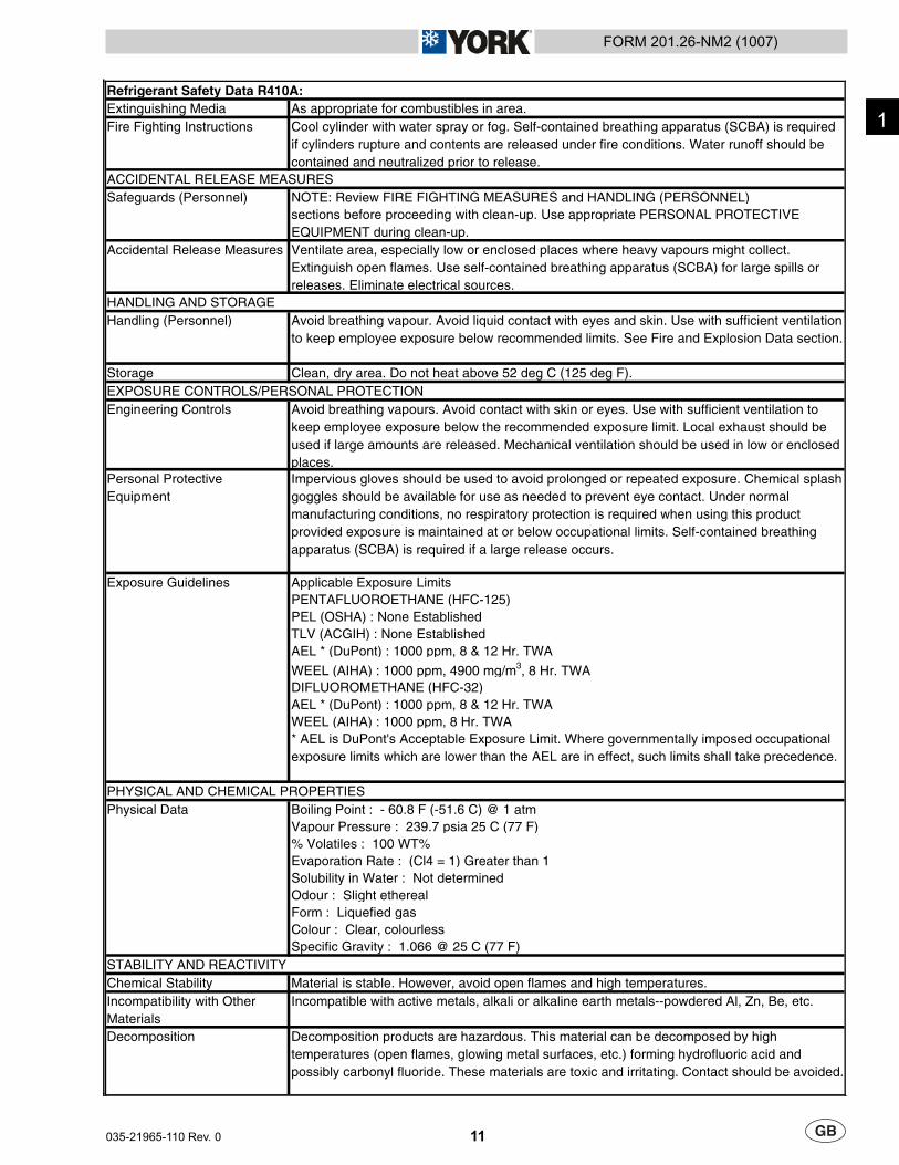
Refrigerant Safety Data R410A:COMPOSITION/INFORMATION ON INGREDIENTS
HAZARDS IDENTIFICATIONPotential Health Effects
11
FORM 201.26-NM2 (1007)
035-21965-110 Rev. 0
Extinguishing Media As appropriate for combustibles in area.Fire Fighting Instructions Cool cylinder with water spray or fog. Self-contained breathing apparatus (SCBA) is required
if cylinders rupture and contents are released under fire conditions. Water runoff should be contained and neutralized prior to release.
NOTE: Review FIRE FIGHTING MEASURES and HANDLING (PERSONNEL)sections before proceeding with clean-up. Use appropriate PERSONAL PROTECTIVE EQUIPMENT during clean-up.
Accidental Release Measures Ventilate area, especially low or enclosed places where heavy vapours might collect. Extinguish open flames. Use self-contained breathing apparatus (SCBA) for large spills or releases. Eliminate electrical sources.
Handling (Personnel) Avoid breathing vapour. Avoid liquid contact with eyes and skin. Use with sufficient ventilation to keep employee exposure below recommended limits. See Fire and Explosion Data section.
Storage Clean, dry area. Do not heat above 52 deg C (125 deg F).
Engineering Controls Avoid breathing vapours. Avoid contact with skin or eyes. Use with sufficient ventilation to keep employee exposure below the recommended exposure limit. Local exhaust should be used if large amounts are released. Mechanical ventilation should be used in low or enclosed places.
Personal Protective Equipment
Impervious gloves should be used to avoid prolonged or repeated exposure. Chemical splash goggles should be available for use as needed to prevent eye contact. Under normal manufacturing conditions, no respiratory protection is required when using this product provided exposure is maintained at or below occupational limits. Self-contained breathing apparatus (SCBA) is required if a large release occurs.
Applicable Exposure LimitsPENTAFLUOROETHANE (HFC-125)PEL (OSHA) : None EstablishedTLV (ACGIH) : None EstablishedAEL * (DuPont) : 1000 ppm, 8 & 12 Hr. TWA
WEEL (AIHA) : 1000 ppm, 4900 mg/m3, 8 Hr. TWADIFLUOROMETHANE (HFC-32)AEL * (DuPont) : 1000 ppm, 8 & 12 Hr. TWAWEEL (AIHA) : 1000 ppm, 8 Hr. TWA* AEL is DuPont's Acceptable Exposure Limit. Where governmentally imposed occupational exposure limits which are lower than the AEL are in effect, such limits shall take precedence.
Boiling Point : - 60.8 F (-51.6 C) @ 1 atmVapour Pressure : 239.7 psia 25 C (77 F)% Volatiles : 100 WT%Evaporation Rate : (Cl4 = 1) Greater than 1Solubility in Water : Not determinedOdour : Slight etherealForm : Liquefied gasColour : Clear, colourlessSpecific Gravity : 1.066 @ 25 C (77 F)
Chemical Stability Material is stable. However, avoid open flames and high temperatures.Incompatibility with Other Materials
Incompatible with active metals, alkali or alkaline earth metals--powdered Al, Zn, Be, etc.
Decomposition Decomposition products are hazardous. This material can be decomposed by high temperatures (open flames, glowing metal surfaces, etc.) forming hydrofluoric acid and possibly carbonyl fluoride. These materials are toxic and irritating. Contact should be avoided.
Refrigerant Safety Data R410A:
Physical Data
STABILITY AND REACTIVITY
HANDLING AND STORAGE
EXPOSURE CONTROLS/PERSONAL PROTECTION
Exposure Guidelines
PHYSICAL AND CHEMICAL PROPERTIES
ACCIDENTAL RELEASE MEASURESSafeguards (Personnel)
1
12 035-21965-110 Rev. 0
FORM 201.26-NM2 (1007)
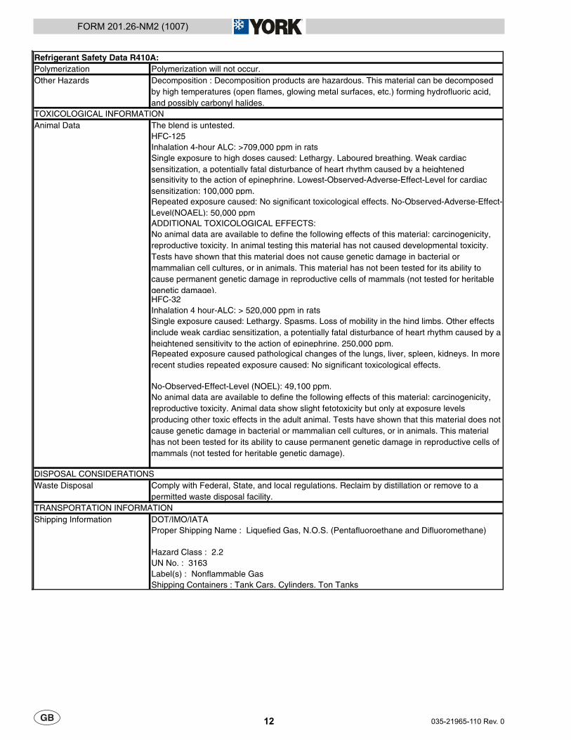
Polymerization Polymerization will not occur.Other Hazards Decomposition : Decomposition products are hazardous. This material can be decomposed
by high temperatures (open flames, glowing metal surfaces, etc.) forming hydrofluoric acid, and possibly carbonyl halides.
The blend is untested.HFC-125Inhalation 4-hour ALC: >709,000 ppm in ratsSingle exposure to high doses caused: Lethargy. Laboured breathing. Weak cardiac sensitization, a potentially fatal disturbance of heart rhythm caused by a heightenedsensitivity to the action of epinephrine. Lowest-Observed-Adverse-Effect-Level for cardiac sensitization: 100,000 ppm.Repeated exposure caused: No significant toxicological effects. No-Observed-Adverse-Effect-Level(NOAEL): 50,000 ppmADDITIONAL TOXICOLOGICAL EFFECTS:No animal data are available to define the following effects of this material: carcinogenicity, reproductive toxicity. In animal testing this material has not caused developmental toxicity. Tests have shown that this material does not cause genetic damage in bacterial or mammalian cell cultures, or in animals. This material has not been tested for its ability to cause permanent genetic damage in reproductive cells of mammals (not tested for heritable genetic damage).HFC-32Inhalation 4 hour-ALC: > 520,000 ppm in ratsSingle exposure caused: Lethargy. Spasms. Loss of mobility in the hind limbs. Other effects include weak cardiac sensitization, a potentially fatal disturbance of heart rhythm caused by a heightened sensitivity to the action of epinephrine. 250,000 ppm.Repeated exposure caused pathological changes of the lungs, liver, spleen, kidneys. In more recent studies repeated exposure caused: No significant toxicological effects.
No-Observed-Effect-Level (NOEL): 49,100 ppm.No animal data are available to define the following effects of this material: carcinogenicity, reproductive toxicity. Animal data show slight fetotoxicity but only at exposure levels producing other toxic effects in the adult animal. Tests have shown that this material does not cause genetic damage in bacterial or mammalian cell cultures, or in animals. This material has not been tested for its ability to cause permanent genetic damage in reproductive cells of mammals (not tested for heritable genetic damage).
Waste Disposal Comply with Federal, State, and local regulations. Reclaim by distillation or remove to a permitted waste disposal facility.
DOT/IMO/IATAProper Shipping Name : Liquefied Gas, N.O.S. (Pentafluoroethane and Difluoromethane)
Hazard Class : 2.2UN No. : 3163Label(s) : Nonflammable GasShipping Containers : Tank Cars. Cylinders. Ton Tanks
DISPOSAL CONSIDERATIONS
TRANSPORTATION INFORMATIONShipping Information
Refrigerant Safety Data R410A:
TOXICOLOGICAL INFORMATIONAnimal Data
13
FORM 201.26-NM2 (1007)
035-21965-110 Rev. 0
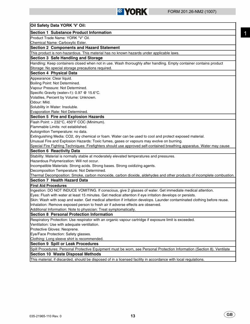
Section 9 Spill or Leak ProceduresSpill Procedures: Personal Protective Equipment must be worn, see Personal Protection Information (Section 8). Ventilate Section 10 Waste Disposal MethodsThis material, if discarded, should be disposed of in a licensed facility in accordance with local regulations.
Ventilation: Use with adequate ventilation.Protective Gloves: Neoprene.Eye/Face Protection: Safety glasses.Clothing: Long sleeve shirt is recommended.
Inhalation: Remove exposed person to fresh air if adverse effects are observed.Additional Information: Note to physician: Treat symptomatically.Section 8 Personal Protection InformationRespiratory Protection: Use respirator with an organic vapour cartridge if exposure limit is exceeded.
First Aid ProceduresIngestion: DO NOT INDUCE VOMITING. If conscious, give 2 glasses of water. Get immediate medical attention.Eyes: Flush with water at least 15 minutes. Get medical attention if eye irritation develops or persists.Skin: Wash with soap and water. Get medical attention if irritation develops. Launder contaminated clothing before reuse.
Incompatible Materials: Strong acids. Strong bases. Strong oxidizing agents.Decomposition Temperature: Not Determined.Thermal Decomposition: Smoke, carbon monoxide, carbon dioxide, aldehydes and other products of incomplete combustion.Section 7 Health Hazard Data
Special Fire Fighting Techniques: Firefighters should use approved self-contained breathing apparatus. Water may cause Section 6 Reactivity DataStability: Material is normally stable at moderately elevated temperatures and pressures.Hazardous Polymerization: Will not occur.
Flammable Limits: not established.Autoignition Temperature: no data.Extinguishing Media: CO2, dry chemical or foam. Water can be used to cool and protect exposed material.Unusual Fire and Explosion Hazards: Toxic fumes, gases or vapours may evolve on burning.
Solubility in Water: Insoluble.Evaporation Rate: Not Determined.Section 5 Fire and Explosion HazardsFlash Point: > 232°C, 450°F COC (Minimum).
Vapour Pressure: Not Determined.Specific Gravity (water=1): 0.97 @ 15.6°C.Volatiles, Percent by Volume: Unknown.Odour: Mild.
Storage: No special storage precautions required.Section 4 Physical DataAppearance: Clear liquid.Boiling Point: Not Determined.
Section 2 Components and Hazard StatementThis product is non-hazardous. This material has no known hazards under applicable laws.Section 3 Safe Handling and StorageHandling: Keep containers closed when not in use. Wash thoroughly after handling. Empty container contains product
Oil Safety Data YORK 'V' Oil:
Section 1 Substance Product InformationProduct Trade Name: YORK "V" Oil.Chemical Name: Carboxylic Ester.
1
14 035-21965-110 Rev. 0
FORM 201.26-NM2 (1007)
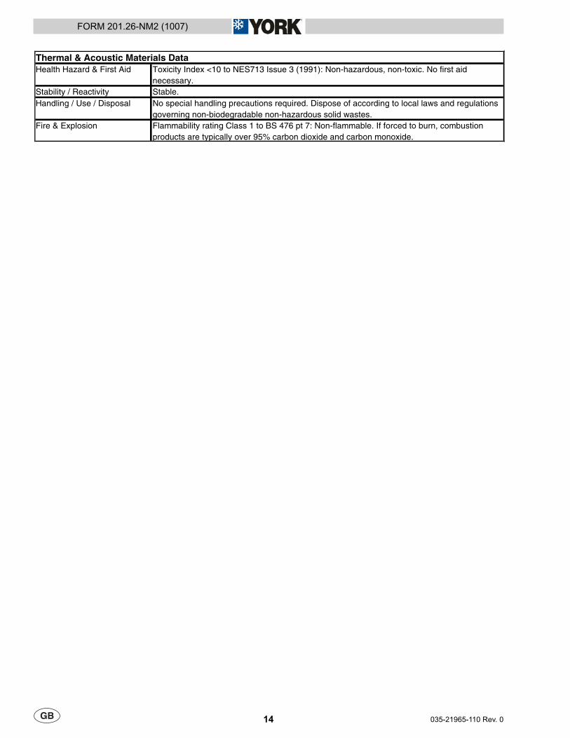
Health Hazard & First Aid Toxicity Index <10 to NES713 Issue 3 (1991): Non-hazardous, non-toxic. No first aid necessary.
Stability / Reactivity Stable.Handling / Use / Disposal No special handling precautions required. Dispose of according to local laws and regulations
governing non-biodegradable non-hazardous solid wastes.Fire & Explosion Flammability rating Class 1 to BS 476 pt 7: Non-flammable. If forced to burn, combustion
products are typically over 95% carbon dioxide and carbon monoxide.
Thermal & Acoustic Materials Data
15
FORM 201.26-NM2 (1007)
035-21965-110 Rev. 0
PRODUCT DESCRIPTION
INTRODUCTION
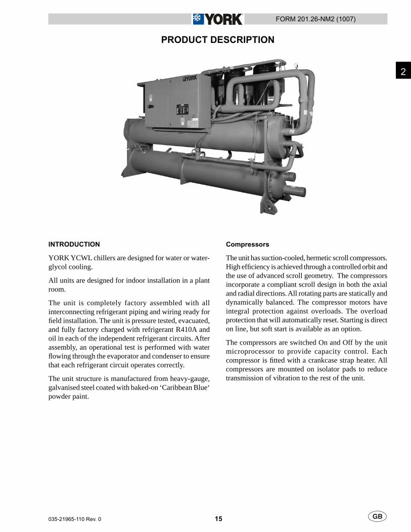
YORK YCWL chillers are designed for water or water-glycol cooling.
All units are designed for indoor installation in a plant room.
The unit is completely factory assembled with all interconnecting refrigerant piping and wiring ready for fi eld installation. The unit is pressure tested, evacuated, and fully factory charged with refrigerant R410A and oil in each of the independent refrigerant circuits. After assembly, an operational test is performed with water fl owing through the evaporator and condenser to ensure that each refrigerant circuit operates correctly.
The unit structure is manufactured from heavy-gauge, galvanised steel coated with baked-on ‘Caribbean Blue‘ powder paint.
Compressors
The unit has suction-cooled, hermetic scroll compressors. High effi ciency is achieved through a controlled orbit and the use of advanced scroll geometry. The compressors incorporate a compliant scroll design in both the axial and radial directions. All rotating parts are statically and dynamically balanced. The compressor motors have integral protection against overloads. The overload protection that will automatically reset. Starting is direct on line, but soft start is available as an option.
The compressors are switched On and Off by the unit microprocessor to provide capacity control. Each compressor is fi tted with a crankcase strap heater. All compressors are mounted on isolator pads to reduce transmission of vibration to the rest of the unit.
2

16 035-21965-110 Rev. 0
FORM 201.26-NM2 (1007)
Refrigerant Circuits
Two independent refrigerant circuits are provided on each unit. Each circuit uses copper refrigerant pipe formed on computer controlled bending machines to reduce the number of brazed joints resulting in a reliable and leak resistant system.
Liquid line components include: a service valve with charging port, a high absorption removable core fi lter-drier, a solenoid valve, a sight glass with moisture indicator and a thermal expansion valve. Liquid lines between the expansion valve and the cooler are covered with fl exible, closed-cell insulation.
Suction line components include: a pressure relief valve, a pressure transducer and a service valve. Optional isolation ball valves are available. Suction lines are covered with fl exible, closed-cell insulation.
Discharge lines include service and isolation (ball) valves, two high-pressure cutout switches, a pressure transducer and a pressure relief valve.
Evaporator
The 2-pass dual circuit shell and tube type direct expansion (DX) evaporator has refrigerant in the tubes and chilled liquid fl owing through the baffl ed shell. The waterside (shell) design working pressure of the cooler is 10.3 bar g. The refrigerant side (tubes) design working pressure is 27.58 bar g. The refrigerant side is protected by pressure relief valve(s).
The evaporator shall have water pass baffl es fabricated from galvanised steel to resist corrosion. Removable heads are provided for access to internally enhanced, seamless, copper tubes. Water vent and drain connections are included. The cooler is insulated with fl exible closed-cell foam.
Water Connection to the evaporator is via victaulic-grooved connections. Flange connections are available as an option.
Condenser
The twin-refrigerant circuit water-cooled condenser is cleanable shell and tubes type with seamless externally fi nned copper tubes rolled into tubes sheets, removable water heads and built-in subcooler. The waterside (tubes) design working pressure is 10 bar g. The refrigerant side (shell) design working pressure is 38.61 bar g. The refrigerant side is protected by pressure relief valve(s).
Water Connection to the condenser is via victaulic-grooved connections. Flange connections are available as an option.
Power and Control Panels
All power and controls are contained in a IP32 cabinet with hinged, latched and gasket sealed outer doors.
The power panel includes:
A factory mounted non-fused disconnect switch with external, lockable handle to enable connection of the unit power supply. The disconnect switch can be used to isolate the power for servicing.
Factory mounted compressor contactors and manual motor starters to provide overload and short circuit protection.
Factory mounted control transformer to convert the unit supply voltage to 110 V - 1 Ø - 50 Hz for the control system.
Control supply fuses and connections for a remote emergency stop device.
The control panel includes:
A Liquid Crystal Display (two display lines of twenty characters per line) with Light Emitting Diode backlighting for easy viewing.
A Colour coded 12-button keypad.
Customer terminal block for control inputs and liquid fl ow switch.
•
•
•
•
•
•
•
17
FORM 201.26-NM2 (1007)
035-21965-110 Rev. 0
The microprocessor control includes:
Automatic control of compressor start/stop, anti-coincidence and anti-recycle timers, automatic pumpdown on shutdown, evaporator pump and unit alarm contacts. Automatic reset to normal chiller operation after power failure.
Remote water temperature reset via a pulse width modulated (PWM) input signal or up to two steps of demand (load) limiting
Software stored in non-volatile memory (EPROM), with programmed setpoints retained in a lithium battery backed real time clock (RTC) memory for a minimum of fi ve years.
Forty character liquid crystal display, with description available in fi ve languages (English, French, German, Spanish or Italian)
Programmable setpoints:
Chilled liquid temperature setpoint and range
Remote reset temperature range
Set daily schedule/holiday for start/stop
Manual override for servicing
Low liquid temperature cutout
Low suction pressure cutout
High discharge pressure cutout
Anti-recycle timer (compressor start cycle time)
Anti-coincident timer (delay compressor starts)
Displayed Data:
Return and leaving liquid temperature
Low leaving liquid temperature cutout setting
Metric or Imperial data
Discharge and suction pressure cutout settings
System discharge and suction pressures
Anti-recycle timer status for each compressor
Anti-coincident system start timer condition
Compressor run status
No cooling load condition
•
•
•
•
•
•
•
•
•
•
•
•
•
•
•
•
•
•
•
•
•
•
Day, date and time
Daily start/stop times
Holiday status
Automatic or manual system lead/lag control
Lead system defi nition
Compressor starts & operating hours (each compressor)
Run permissive status
Number of compressors running
Liquid solenoid valve status
Load & unload timer status
Water pump status
System Safeties:
Cause individual compressors to perform auto shut down and require manual reset in the event of 3 trips in a 90-minute time period:
High discharge pressure
Low suction pressure
High pressure switches
Motor protector
Unit Safeties:
Are automatic reset and cause compressor to shut down
Low leaving chilled liquid temperature
Under voltage
Loss of liquid fl ow (through fl ow switch)
Alarm Contacts:
Low leaving chilled liquid temperature
Low voltage
Low battery
High discharge pressure (per system)
Low suction pressure (per system)
•
•
•
•
•
•
•
•
•
•
•
•
•
•
•
•
•
•
•
•
•
•
•
•
•
2
18 035-21965-110 Rev. 0
FORM 201.26-NM2 (1007)
ACCESSORIES AND OPTIONS
Soft Starters
Factory mounted soft starters reduce the inrush current to the last compressor on each refrigerant circuit. They are preset so that no fi eld adjustment is required.
Power Factor Correction
Factory mounted passive (static) power factor correction capacitors to correct unit compressor power factors to a target of 0.9 (depending on operating conditions). This option is Special Quotation only, contact YORK / Johnson Controls for details.
Language LCD and Keypad
English, French, German, Italian and Spanish unit LCD read-out and keypad available. Standard language is English.
Non-reversible Heat Pump
Allows the chiller to control the leaving condenser liquid temperature (LCLT). The unit will load and unload to maintain fi xed LCLT. This option is Special Quotation only, contact YORK / Johnson Controls for details.
38 mm Evaporator Insulation
Double thickness insulation provided for enhanced effi ciency, and low temperature applications.
Pressure Relief (CE/PED) Service Valve Kit
Each relief valve is mounted on a sealable ball valve to aid maintenance.
Dual Pressure Relief Valves
Two pressure relief valves mounted on a 3-way valve in parallel of which one is operational and the other one assist during maintenance.
Suction Service Valves
A ball valve is added to each suction line pipework for isolation.
Victaulic Flange Kit
Victaulic PN10 Flange joint kit supplied loose for fi eld installation. Includes fl ange and companion fl ange and all necessary nuts, bolts and gaskets.
Compressor Acoustic Blankets
Each compressor is individually enclosed in an acoustic sound blanket. The sound blankets are made with one layer of acoustical absorbent textile fi bre of 15 mm thickness and one layer of anti vibrating heavy material thickness of 3 mm. Both are closed by two sheets of welded PVC, reinforced for temperature and UV resistance.
Final overspray
Overspray painting in Caribbean Blue of the unit after assembly. (Except Compressors)
Flow switch
Vapour Proof, paddle-type, 10.3 barg DWP, -29°C to 121°C with 1”NPT connection for upright mounting in horizontal pipe. This fl ow switch or its equivalent must be supplied with each unit to protect vessels from loss of liquid fl ow (Field Mounted)
Differential Pressure Switch
Alternative to the paddle type fl ow switch. 0-3 bar range with ¼” NPTE pressure connections
Neoprene Pad Isolators
Recommended for normal installations (field mounted).
25 mm Spring Isolators
Level adjustable, spring and cage type isolators for mounting under the unit base rails (fi eld mounted).
19
FORM 201.26-NM2 (1007)
035-21965-110 Rev. 0
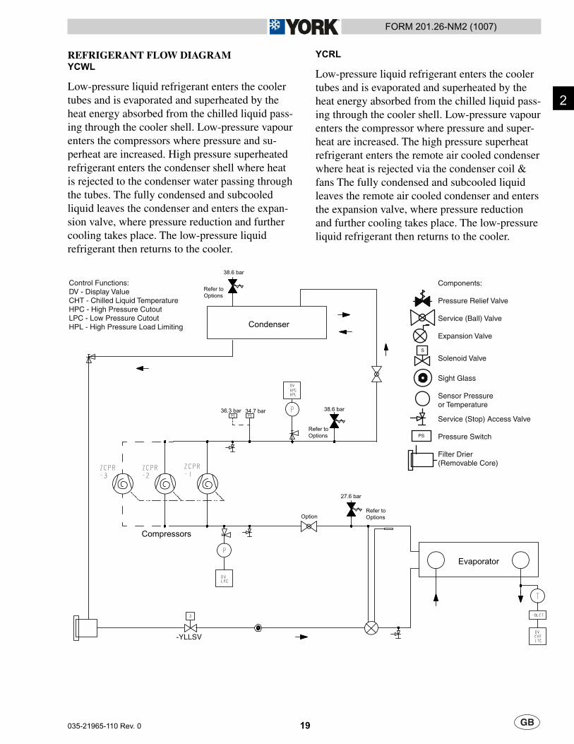
REFRIGERANT FLOW DIAGRAMYCWL
Low-pressure liquid refrigerant enters the cooler tubes and is evaporated and superheated by the heat energy absorbed from the chilled liquid pass-ing through the cooler shell. Low-pressure vapour enters the compressors where pressure and su-perheat are increased. High pressure superheated refrigerant enters the condenser shell where heat is rejected to the condenser water passing through the tubes. The fully condensed and subcooled liquid leaves the condenser and enters the expan-sion valve, where pressure reduction and further cooling takes place. The low-pressure liquid refrigerant then returns to the cooler.
Evaporator
Condenser
Compressors
Refer toOptions
38.6 bar
27.6 bar
Refer toOptions
38.6 bar
Refer toOptions
Components:
Pressure Relief Valve
Service (Ball) Valve
Expansion Valve
Solenoid Valve
Sight Glass
Sensor Pressureor Temperature
Service (Stop) Access Valve
Pressure Switch
Filter Drier(Removable Core)
S
PS
Option
Control Functions:DV - Display ValueCHT - Chilled Liquid TemperatureHPC - High Pressure CutoutLPC - Low Pressure CutoutHPL - High Pressure Load Limiting
-YLLSV
34.7 bar36.3 bar
YCRL
Low-pressure liquid refrigerant enters the cooler tubes and is evaporated and superheated by the heat energy absorbed from the chilled liquid pass-ing through the cooler shell. Low-pressure vapour enters the compressor where pressure and super-heat are increased. The high pressure superheat refrigerant enters the remote air cooled condenser where heat is rejected via the condenser coil & fans The fully condensed and subcooled liquid leaves the remote air cooled condenser and enters the expansion valve, where pressure reduction and further cooling takes place. The low-pressure liquid refrigerant then returns to the cooler.
2
20 035-21965-110 Rev. 0
FORM 201.26-NM2 (1007)
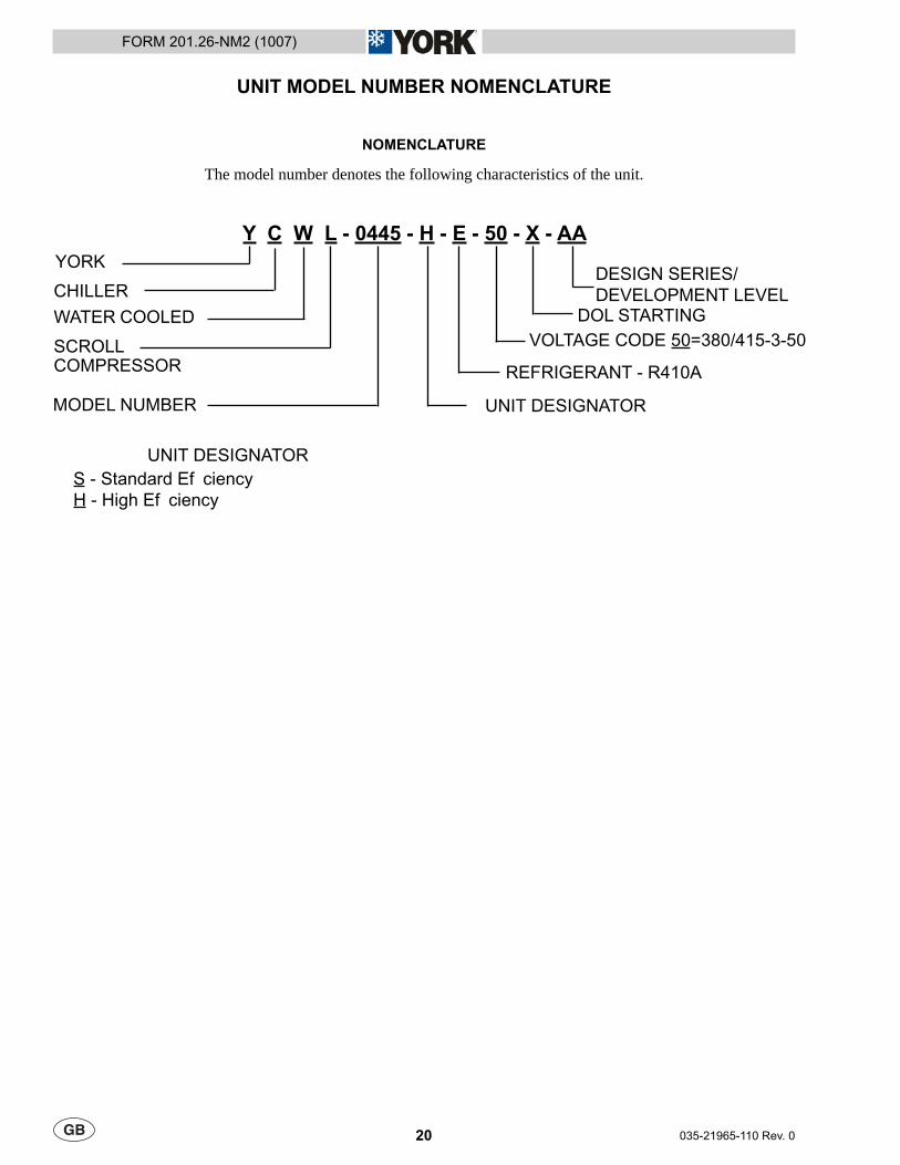
NOMENCLATURE
The model number denotes the following characteristics of the unit.
UNIT MODEL NUMBER NOMENCLATURE
Y C W L - 0445 - H - E - 50 - X - AAYORK
CHILLER
WATER COOLED
SCROLLCOMPRESSOR
MODEL NUMBER UNIT DESIGNATOR
S - Standard Ef ciencyH - High Ef ciency
REFRIGERANT - R410A
VOLTAGE CODE 50=380/415-3-50
UNIT DESIGNATOR
DESIGN SERIES/DEVELOPMENT LEVEL
DOL STARTING
21
FORM 201.26-NM2 (1007)
035-21965-110 Rev. 0
HANDLING AND STORAGE
DELIVERY AND STORAGE
To ensure consistent quality and maximum reliability, all units are tested and inspected before leaving the factory. Units are shipped completely assembled and containing refrigerant under pressure. Units are shipped without export crating unless crating has been specifi ed on the Sales Order.
If the unit is to be put into storage, prior to installation, the following precautions should be observed:
Ensure that all openings, such as water connections, are securely capped.
Do not store where exposed to ambient air temperatures exceeding 46°C.
The unit should be stored in a location where there is minimal activity in order to limit the risk of accidental physical damage.
To prevent inadvertent operation of the pressure relief devices the unit must not be steam cleaned.
It is recommended that the unit is periodically inspected during storage.
INSPECTION
Remove any transit packing and inspect the unit to ensure that all components have been delivered and that no damage has occurred during transit. If any damage is evident, it should be noted on the carrier’s freight bill and a claim entered in accordance with the instructions given on the advice note.
•
•
•
•
•
Major damage must be reported immediately to your local Johnson Controls representative.
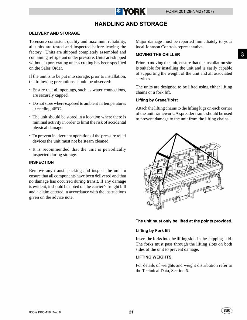
MOVING THE CHILLER
Prior to moving the unit, ensure that the installation site is suitable for installing the unit and is easily capable of supporting the weight of the unit and all associated services.
The units are designed to be lifted using either lifting chains or a fork lift.
Lifting by Crane/Hoist
Attach the lifting chains to the lifting lugs on each corner of the unit framework. A spreader frame should be used to prevent damage to the unit from the lifting chains.
The unit must only be lifted at the points provided.
Lifting by Fork lift
Insert the forks into the lifting slots in the shipping skid. The forks must pass through the lifting slots on both sides of the unit to prevent damage.
LIFTING WEIGHTS
For details of weights and weight distribution refer to the Technical Data, Section 6.
3

22 035-21965-110 Rev. 0
FORM 201.26-NM2 (1007)
This Page Left Intentionally Blank
23
FORM 201.26-NM2 (1007)
035-21965-110 Rev. 0
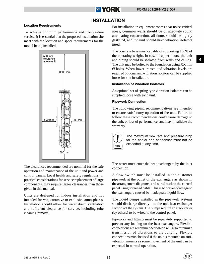
INSTALLATIONLocation Requirements
To achieve optimum performance and trouble-free service, it is essential that the proposed installation site meet with the location and space requirements for the model being installed.
Control P
anel
3500 mm
800 mm
500 mm clearanceabove unit
800 mm
800 mm
The clearances recommended are nominal for the safe operation and maintenance of the unit and power and control panels. Local health and safety regulations, or practical considerations for service replacement of large components, may require larger clearances than those given in this manual.
Units are designed for indoor installation and not intended for wet, corrosive or explosive atmospheres. Installation should allow for water drain, ventilation and suffi cient clearance for service, including tube cleaning/removal.
For installation in equipment rooms near noise-critical areas, common walls should be of adequate sound attenuating construction, all doors should be tightly gasketed, and the unit should have vibration isolators fi tted.
The concrete base must capable of supporting 150% of the operating weight. In case of upper fl oors, the unit and piping should be isolated from walls and ceiling. The unit may be bolted to the foundation using XX mm Ø holes. When lower transmitted vibration levels are required optional anti-vibration isolators can be supplied loose for site installation.
Installation of Vibration Isolators
An optional set of spring type vibration isolators can be supplied loose with each unit.
Pipework Connection
The following piping recommendations are intended to ensure satisfactory operation of the unit. Failure to follow these recommendations could cause damage to the unit, or loss of performance, and may invalidate the warranty.
The maximum fl ow rate and pressure drop for the cooler and condenser must not be exceeded at any time.
The water must enter the heat exchangers by the inlet connection.
A flow switch must be installed in the customer pipework at the outlet of the exchangers as shown in the arrangement diagrams, and wired back to the control panel using screened cable. This is to prevent damage to the exchangers caused by inadequate liquid fl ow.
The liquid pumps installed in the pipework systems should discharge directly into the unit heat exchanger sections of the system. The pumps require an auto-starter (by others) to be wired to the control panel.
Pipework and fi ttings must be separately supported to prevent any loading on the heat exchangers. Flexible connections are recommended which will also minimize transmission of vibrations to the building. Flexible connections must be used if the unit is mounted on anti-vibration mounts as some movement of the unit can be expected in normal operation.
4
24 035-21965-110 Rev. 0
FORM 201.26-NM2 (1007)
Pipework and fi ttings immediately next to the heat exchangers should be readily de-mountable to enable cleaning prior to operation, and to facilitate visual inspection of the exchanger nozzles.
Each heat exchanger must be protected by a strainer, preferably of 20 microns, fi tted as close as possible to the liquid inlet connection, and provided with a means of local isolation.
The heat exchangers must not be exposed to fl ushing velocities or debris released during flushing. It is recommended that a suitably sized by-pass and valve arrangement be installed to allow flushing of the pipework system. The by-pass can be used during maintenance to isolate the heat exchanger without disrupting fl ow to other units.
Thermometer and pressure gauge connections should be provided on the inlet and outlet connections of each heat exchanger.
Drain and air vent connections should be provided at all low and high points in the pipework to permit drainage of the system, and to vent any air in the pipes.
Liquid systems at risk of freezing, due to low ambient temperatures, should be protected using insulation and heater tape and/or a suitable glycol solution. The liquid pumps must also be used to ensure liquid is circulated when the ambient temperature approaches freezing point. Insulation should also be installed around the heat exchanger nozzles.
Water Treatment
The unit performance given in the Design Guide is based on a fouling factor of 0.044 m² °C/kW. Dirt, scale, grease and certain types of water treatment will adversely affect the heat exchanger surfaces and therefore unit performance. Foreign matter in the water system(s) can increase the heat exchanger pressure drop, reducing the fl ow rate and causing potential damage to the heat exchanger tubes.
Aerated, brackish or salt water is not recommended for use in the water systems. Johnson Controls recommends that a water treatment specialist be consulted to determine that the proposed water composition will not affect the evaporator materials of carbon steel and copper. The pH value of the water fl owing through the heat exchangers must be kept between 7 and 8.5.
For unit operation with chilled liquid temperatures leaving the cooler at below 4.5°C, glycol solutions should be used to help prevent freezing. This manual gives recommended solution strength with water, as a percentage by weight, for the most common types of glycol. It is important to check glycol concentration regularly to ensure adequate concentration and avoid possible freeze-up in the cooler.
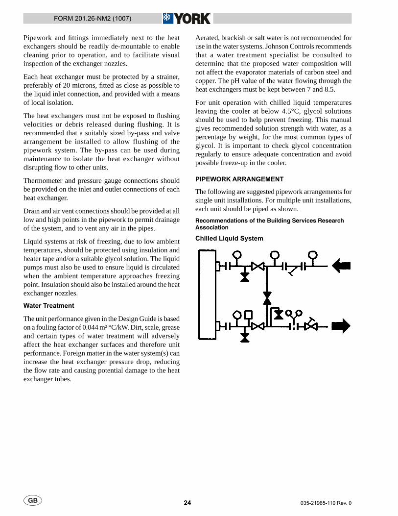
PIPEWORK ARRANGEMENT
The following are suggested pipework arrangements for single unit installations. For multiple unit installations, each unit should be piped as shown.Recommendations of the Building Services Research Association
Chilled Liquid System
25
FORM 201.26-NM2 (1007)
035-21965-110 Rev. 0
Refrigerant Relief Valve Piping
The compressor, cooler and condensers are each protected against internal refrigerant over-pressure and fi re by refrigerant relief valves. The pressure relief valve is set at the design pressure of the system and has discharge capacity required by the relevant standard.
It is recommended that each valve should be piped to the exterior of the building so that when the valve is activated the release of high pressure gas and liquid cannot be a danger or cause injury.
The size of any pipework attached to a relief valve must be of suffi cient diameter so as not to cause resistance to the operation of the valve. For critical or complex installations refer to EN13136.
Unless otherwise specifi ed by local regulations, the internal diameter depends on the length of pipe required and can be estimated with the following formula:
D5=1.447 x L
Where:
D = minimum pipe internal diameter (cm)
L = length of pipe (m).
If relief pipework is common to more than one valve its cross sectional area must be at least the total required by each valve. Valve types should not be mixed on a common pipe. Precautions should be taken to ensure that the exit of relief valves/vent pipe remain clear of obstructions at all times.
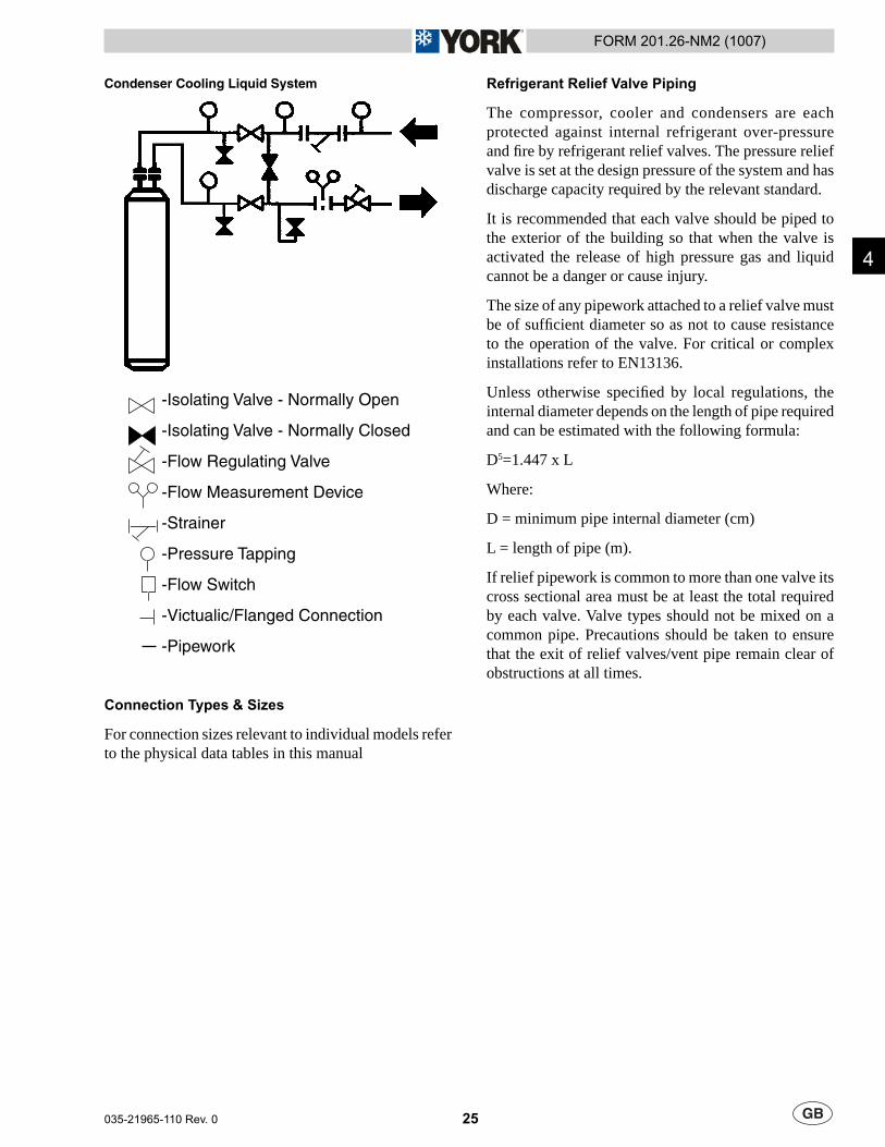
Condenser Cooling Liquid System
-Isolating Valve - Normally Open
-Isolating Valve - Normally Closed
-Flow Regulating Valve
-Flow Measurement Device
-Strainer
-Pressure Tapping
-Flow Switch
-Victualic/Flanged Connection
-Pipework
Connection Types & Sizes
For connection sizes relevant to individual models refer to the physical data tables in this manual
4

26 035-21965-110 Rev. 0
FORM 201.26-NM2 (1007)
Condenser Cooling Liquid Systems
For primary cooling of units, condensers are usually piped in conjunction with a cooling tower or a dry cooler, although in some cases they can be cooled by well water.
With liquid cooled units it is necessary to control coolant fl ow and / or temperature into the condenser to maintain refrigerant pressure as constant as possible to ensure satisfactory operation of the expansion valves.Direct Pressure Control (by others)
With YCWL units it is possible, if desired, to control the condenser cooling liquid inlet temperature / fl ow directly from the unit refrigerant pressure.
The refrigerant pressure can either be used to control cooling tower / dry cooler effectiveness by controlling fans or dampers on the tower, or to control condenser fl ow using a three way bypass valve.
The aim is to maintain a stable discharge pressure as low as possible, but at least 4.8 bar above suction pressure. This can be done at a fi xed value above the highest expected suction pressure, or by also measuring suction pressure and using differential control. In either case condenser cooling liquid fl ow and temperature limits must also be observed.
Inlet Temperature Control (by others)
For a cooling tower / dry cooler system, the simplest forms of control are to use fan cycling, fan speed control, or air damper control, with the tower having a thermostat in its sump. This will ensure stable condenser cooling liquid temperature sensing at design conditions and should be adjusted to ensure a condenser cooling liquid entering temperature of not lower than 18°C at lower ambient conditions.
If these methods are not available, or a cooling tower is not the source of cooling water, then a three way valve recirculation system can be used with control based on condenser inlet liquid temperature. In this case the objective is to maintain the inlet cooling liquid temperature as low as possible, although still observing the minimum limit of 18°C.
27
FORM 201.26-NM2 (1007)
035-21965-110 Rev. 0
ELECTRICAL CONNECTION
The following connection recommendations are intended to ensure safe and satisfactory operation of the unit. Failure to follow these recommendations could cause harm to persons, or damage to the unit, and may invalidate the warranty.
No additional controls (relays, etc.) should be mounted in the control panel. Power and control wiring not connected to the control panel should not be run through the control panel. If these precautions are not followed it could lead to a risk of electrocution. In addition, electrical noise could cause malfunctions or damage the unit and its controls.
Power Wiring
These units are suitable for 380 or 400 V, 3 phase, 50 Hz nominal supplies only.
All electrical wiring should be carried out in accordance with local regulations. Route properly sized cables to the cable entries in the top of the power panel.
In accordance with EN 60204 it is the responsibility of the user to install over current protection devices between the supply conductors and the power supply terminals on the unit.
To ensure that no eddy currents are set up in the power panel, the cables forming each 3 phase power supply must enter via the same cable entry.
All sources of supply to the unit must be taken via a common point of isolation (not supplied by Johnson Controls).
Single Point Power Supply Wiring
All models require one fi eld provided 400 V, 3Ø, 50 Hz + PE (Protected Earth) supply to the unit with circuit protection.
Connect the 3 phase supply to the non-fused disconnect switch located in the power panel using M10 lugs
Connect the earth wire to the main protective earth terminal located in the power panel.
Remote Emergency Stop Device
If required, a remote emergency stop device may be wired into the unit. This device should be rated at 16 amps, 110 V, AC-15. The device should be wired into terminals L and 5 in the power panel after removing the factory fi tted link.
Control Wiring - Voltage Free Contacts
All wiring to the voltage free contact terminal block requires a supply provided by the customer maximum voltage 254 Vac, 28 Vdc.
The customer must take particular care deriving the supplies for the voltage free terminals with regard to a common point of isolation. Thus, these circuits when used must be fed via the common point of isolation so the voltage to these circuits is removed when the common point of isolation to the unit is opened. This common point of isolation is not supplied by Johnson Controls.
In accordance with EN 60204 it is recommended that the customer wiring to these terminals uses orange wires. This will ensure that circuits not switched off by the units supply disconnecting device are distinguished by colour, so that they can easily be identifi ed as live even when the unit disconnecting devices are off. The Johnson Controls voltage free contacts are rated at 125 VA.
All inductive devices (relays) switched by the Johnson Controls voltage free contacts must have their coil suppressed using standard RC suppressors. If these precautions are not followed, electrical noise could cause malfunctions or damage to the unit and its controls.
Chilled Liquid Pump Starter
Terminals 23 and 24 close to start the liquid pump. This contact is closed if there is a ‘Leaving Liquid Temperature Cutout’ or any of the compressors are running or the daily schedule is not calling for a shutdown with the unit switch on.
The contact must be used to ensure that the pump is running in the event of a ‘Leaving Liquid Temperature Cutout’.
The pump contact will not close to run the pump if the unit has been powered up for less than 30 seconds, or if the pump has run in the last 30 seconds, to prevent pump motor overheating.
4
28 035-21965-110 Rev. 0
FORM 201.26-NM2 (1007)
Run Contacts
Terminals 25 and 26 close to indicate that refrigerant system 1 is running and terminals 27 and 28 close to indicate that refrigerant system 2 is running.
Alarm Contacts
Each refrigerant system has a voltage-free normally open contact that will close when control power is applied to the panel, if no fault conditions are present. When a fault occurs which locks a system out, or there is a power failure the contact opens. To obtain a system alarm signal, connect the alarm circuit to terminals 29 and 30 for No. 1 system and terminals 31 and 32 for No. 2 system.
Control Wiring - System Inputs
All wiring to the control terminal block (nominal 30 Vdc) must be run in screened cable, with the screen earthed at the panel end only. Run screened cable separately from mains cable to avoid electrical noise pick-up.
The voltage free contacts must be suitable for 30 Vdc (gold contacts recommended). If the voltage free contacts form part of a relay or contactor, the coil of the device must be suppressed using a standard RC suppressor. The above precautions must be taken to avoid electrical noise which could cause a malfunction or damage to the unit and its controls.
Flow Switch
A chilled liquid fl ow switch of suitable type must be connected to terminals 13 and 14 to provide adequate protection against loss of liquid fl ow.
Remote Start/Stop
Connect a remote switch to terminals 13 and 51 to provide remote start/stop control if required.
Remote Reset of Chilled Liquid Setpoint
The PWM input (terminals 13 and 20) allows reset of the chilled liquid setpoint by supplying a ‘timed’ contact closure. Refer to Section 6 for details.
Remote Load Limiting
Load limiting prevents the unit from loading beyond a desired value. The unit % load limit depends on the number of compressors on the unit. The load limit inputs to terminals 13 and 21 work in conjunction with the PWM input to terminals 13 and 20.
Heat Pump Kit
When the special quotation Non-reversible Heat Pump Option is fi tted the heat pump mode is selected by closing a voltage free contact between terminals 13 and 50.
EMS Analogue Input
Provides a means of resetting the leaving chilled liquid temperature from the BAS/EMS. Accepts 4 to 20 mA, 0 to 20 mA, 0 to 10 Vdc or 2-10 Vdc. Connect to terminal A+ and A-.
BACnet
Enable communications with building protocol systems using BACnet protocol. Connect through standard RS485 port.
29
FORM 201.26-NM2 (1007)
035-21965-110 Rev. 0
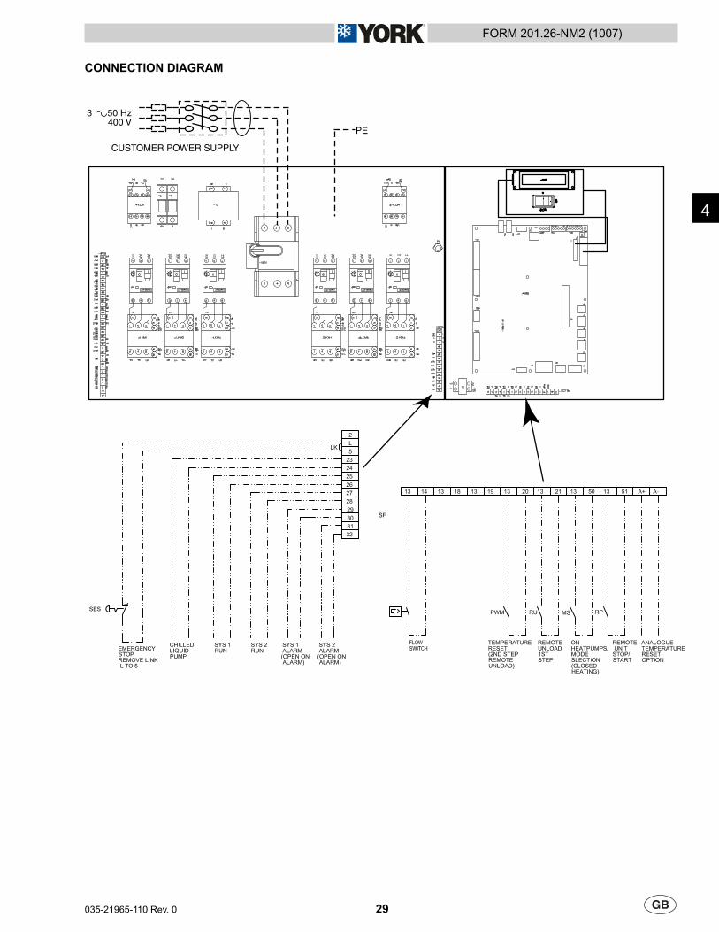
CONNECTION DIAGRAM
CUSTOMER POWER SUPPLY
PE
3 50 Hz400 V
4

30 035-21965-110 Rev. 0
FORM 201.26-NM2 (1007)
This Page Left Intentionally Blank

31
FORM 201.26-NM2 (1007)
035-21965-110 Rev. 0
COMMISSIONINGPREPARATION
Commissioning of this unit should only be carried out by Johnson Controls Authorised personnel.
The unit On/Off switch on the front of the control panel has been set to the Off position at the factory. This switch must remain in the Off position, preventing running of the unit until commissioned by Authorised personnel. If the switch has been set to the On position before commissioning then it must be reported to Johnson Controls otherwise the warranty may be invalidated.
Preparation - Power Off
The following checks should be made with the customer supply/supplies to the unit switched OFF.
Inspection: Inspect unit for installation damage. If found take action and/or repair as appropriate.
Refrigerant charge: Units are normally shipped as standard with a full refrigerant operating charge. Check that refrigerant pressure is present in both systems and that no leaks are apparent. If no pressure is present a leak test must be undertaken, the leak(s) located and repaired. Repaired systems must be evacuated with a suitable vacuum pump/recovery unit as appropriate to below 100 microns before charging.
Do not charge liquid refrigerant with static water in the evaporator. Care must also be taken to charge liquid refrigerant slowly to avoid excessive thermal stress at the charging point.
Once the vacuum is broken, charge with the full operating charge as given in Section 9.
Liquid sub-cooling measured at the liquid line should be between 8.5 and 11.0 °C at circuit full load. Sub-cooling is determined by the level of refrigerant charge in each system.
Valves: Ensure that the compressor discharge and suction service valves are set correctly (OPEN).
Compressor oil: The oil level in multiple scroll compressors (piped in parallel) must be checked directly after all compressors are shut down and have been allowed time to stabilise.
The oil level must be between the bottom and middle of the oil sight glass mounted in the oil equalising line between the compressors.
Isolation/protection: Verify that all sources of electrical supply to the unit are taken from a point of isolation.
Control panel: Check the panel to see that it is free of foreign materials (wire, metal chips, etc.) and clean out if required.
Power connections: Check the customer power cables are connected correctly. Ensure that connections of power cables within the power panel to the non-fused switch disconnects are tight.
Earthing: Verify that the unit earth terminal is properly connected to a suitable earthing point. Ensure that all unit internal earth connections are tight.
Compressor Overload Settings: Check the factory setting of the Compressor Motor Starters as follows:
SYS 1 SYS 2YCWL0240SE 31.2 31.2YCWL0290SE 35.9 35.9YCWL0345SE 51.6 35.9YCWL0395SE 51.6 51.6YCWL0200HE 23.8 23.8YCWL0230HE 31.2 23.8YCWL0260HE 31.2 31.2YCWL0300HE 35.9 35.9YCWL0345HE 51.6 35.9YCWL0385HE 31.2 31.2YCWL0425HE 51.6 51.6YCWL0445HE 35.9 35.9YCWL0530HE 51.6 35.9YCWL0610HE 51.6 51.6
Supply voltage: Verify that the site voltage supply corresponds to the unit requirement and is within the limits given in the Technical Data, Section 6. The phase imbalance should less than 2% of the average voltage.
5
32 035-21965-110 Rev. 0
FORM 201.26-NM2 (1007)
Soft Start (Option)
Due to vibration during transport the soft starter internal bypass contactor may be in a undefi ned state. If the following procedure is not followed this may result in the compressor momentarily starting when the unit power is fi rst turned on.
IMPORTANTDuring commissioning or if the soft start is replaced the following procedure MUST BE PERFORMED.
1. With the unit switch and unit switch disconnect set to OFF to isolate the unit, remove the fuses from the compressors fi tted with a soft starter.
2. Turn ON the unit switch disconnect to turn on the unit supply and thus apply control circuit voltage to soft starter terminals A1 and A2.
3. Turn OFF the unit disconnect switch and refi t the compressor fuses.
Switch Settings: Ensure that the unit On/Off toggle switch on the control panel is set to OFF. Set the non-fused disconnect switch to ON. The customers disconnection devices can now be set to ON.
THE MACHINE IS NOW LIVE!
Crankcase Heaters: Verify the heaters are energised.
Depending upon the ambient temperature the crankcase heaters must be on for 12 to 24 hours before start-up.
Water System: Verify that the chilled liquid system has been installed correctly, and has been commissioned with the correct direction of water fl ow through the evaporator. Inlet should be at the refrigerant pipework connection end of the evaporator. Purge air from the evaporator using the air vent mounted in the pipework.
Verify that the cooling liquid system has been installed correctly, and has been commissioned with the correct direction of water fl ow through the condenser. Purge air from the evaporator using the air vent mounted in the pipework.
Flow rates and pressure drops must be within the limits given in the Technical Data, Section 6. Operation outside of these limits is undesirable and could cause damage.
Flow switch: Verify a chilled liquid fl ow switch is correctly fi tted in the customer’s pipework on the cooler outlet, and wired into the control panel correctly.
Temperature sensor(s): Ensure the leaving (-BLCT) liquid temperature sensor is coated with heat conductive compound (Part No. 013-00890-000) and are inserted in the water inlet and outlet sensor pockets of the cooler.
Control supply: Verify the control panel display is illuminated.
HP cut-out reset: Check that the hand reset mechanical high pressure cut-outs mounted on the discharge lines are at the correct setting and are reset.
Programmed options: Verify that the options factory programmed into the Microprocessor Control Centre are in accordance with the customers order requirements by pressing the ‘OPTIONS’ key on the keypad and reading the settings from the display. Refer also to the MBCS Manual for notes and explanation of messages.
Programmed settings: Ensure the system cut-out and operational settings are in accordance with operational requirements by pressing the ‘PROGRAM’ key (refer to MBCS Manual).
Date & time: Press the ‘CLOCK’ key and set the date and time (refer to MBCS Manual).
Start/Stop schedule: Programme the daily and holiday start/stop by pressing the ‘SCHEDULE/ADVANCE DAY’ key (refer to MBCS Manual).
Setpoints: Set the required leaving chilled liquid temperature set-point and control range using the ‘COOLING SETPOINTS’ key (refer to MBCS Manual).
Compressor Operation: Use the ‘OPTIONS’ key to switch off each refrigerant system in turn (refer to MBCS Manual) and then check the compressors on the active system:
Connect a manifold gauge to each refrigerant circuit suction and discharge service valves and temporarily start each compressor and check that the discharge pressure rises and the suction pressure decreases to ensure that the compressors are operating in the correct direction. Any faults found must be corrected before starting the unit.
After completing the checks on both circuits, set both systems to on using the ‘OPTIONS’ key.
33
FORM 201.26-NM2 (1007)
035-21965-110 Rev. 0
5
FIRST TIME START-UP
During the commissioning period there should be suffi cient heat load to run the unit under stable full load operation to enable the unit controls, and system operation to be set up correctly and a commissioning log taken. Read the following section in conjunction with the MBCS Manual, then proceed step by step as follows:
Interlocks: Verify that liquid is fl owing through the evaporator and that heat load is present. Ensure that any remote run interlocks are in the run position and that the run schedule requires the unit to run or is overridden.
Start-up: Set the unit switch to the ON position to start the unit (there may be a few seconds delay before the fi rst compressor starts because of the anti-recycle timer). Be ready when each compressor starts, to switch the unit off immediately if any unusual noises or other adverse conditions develop. Refer to the Section 6 for the normal operating sequence from start-up.
Refrigerant fl ow: When a compressor starts a fl ow of liquid refrigerant will be seen in the liquid line sight glass. After several minutes operation and providing a full charge of refrigerant is in the system, the bubbles will disappear and be replaced by a solid column of liquid. Check that the moisture indicator is satisfactory (Green).
System Operation: Use the ‘OPER DATA’ key to check the system pressures and temperatures.
Suction Superheat: Check suction superheat at steady full system load only. It is important that no bubbles show in the liquid line sight glass. Measure suction temperature on the copper line about 150 mm before the compressor suction service valve. Measure suction pressure at the compressor service valve. Superheat should be 5.5°C to 7.0°C relative to the ‘dew’ temperature.
Thermal Expansion valve adjustment: The expansion valves are factory set and should not need adjustment. If any superheat values are out of range, however, the expansion valve adjusting screw should be adjusted no more than 1 turn at a time (‘in’ to increase superheat, ‘out’ to decrease superheat), allowing at least 10 minutes for the valve to stabilise before rechecking the value of superheat.
Subcooling: Check liquid subcooling at steady full compressor load only. Measure liquid line temperature on the copper line beside the main liquid line service valve. Measure liquid pressure at the liquid line service valve. Subcooling should be 5°C to 7°C relative to the ’bubble’ temperature. If subcooling is out of range add or remove refrigerant as required. Do not overcharge the unit.
General operation: After completion of the above checks for System 1 repeat the process for system 2. In addition, check that loading occurs as specifi ed in the Section 6 and that general operation is correct.

34 035-21965-110 Rev. 0
FORM 201.26-NM2 (1007)
This Page Left Intentionally Blank
35
FORM 201.26-NM2 (1007)
035-21965-110 Rev. 0
TECHNICAL DATA
6
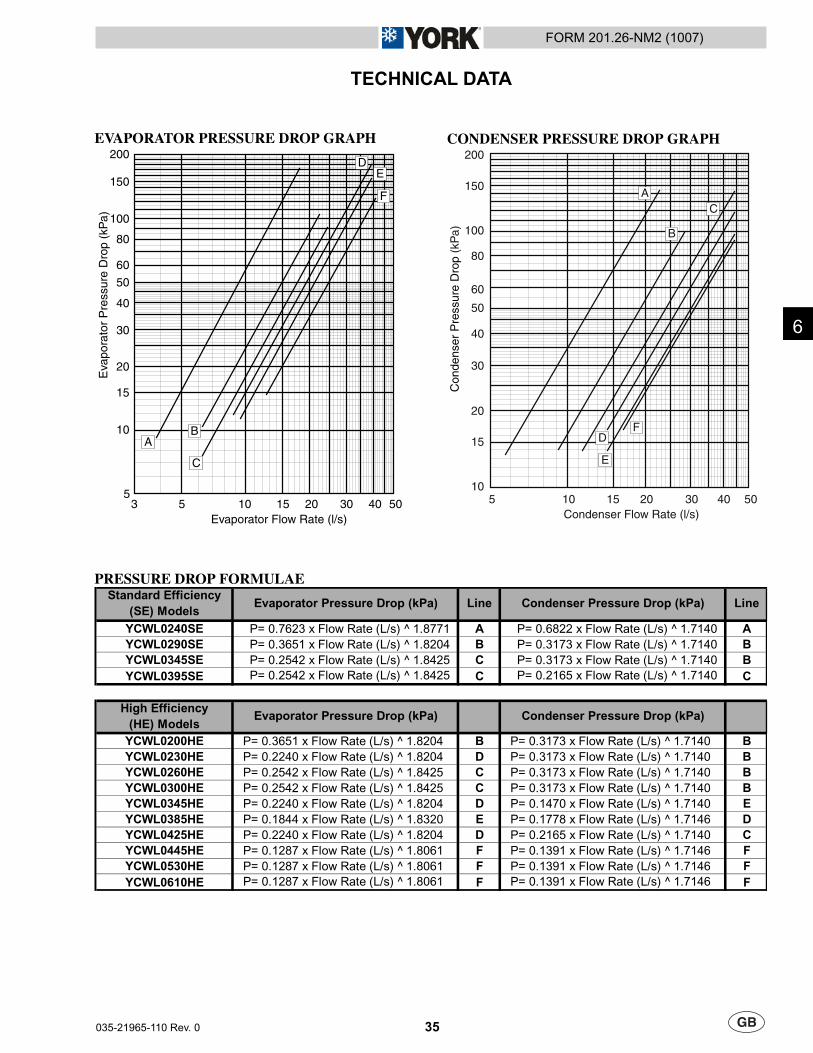
EVAPORATOR PRESSURE DROP GRAPH
3 5 10 15 20 30 40 505
10
15
20
200
150
100
80
60
50
30
40
Evaporator Flow Rate (l/s)
Eva
pora
tor
Pre
ssur
e D
rop
(kP
a)
F
AB
C
DE
PRESSURE DROP FORMULAE
YCWL0240SE P= 0.7623 x Flow Rate (L/s) ^ 1.8771 A P= 0.6822 x Flow Rate (L/s) ^ 1.7140 A
YCWL0290SE P= 0.3651 x Flow Rate (L/s) ^ 1.8204 B P= 0.3173 x Flow Rate (L/s) ^ 1.7140 B
YCWL0345SE P= 0.2542 x Flow Rate (L/s) ^ 1.8425 C P= 0.3173 x Flow Rate (L/s) ^ 1.7140 B
YCWL0395SE P= 0.2542 x Flow Rate (L/s) ^ 1.8425 C P= 0.2165 x Flow Rate (L/s) ^ 1.7140 C
YCWL0200HE P= 0.3651 x Flow Rate (L/s) ^ 1.8204 B P= 0.3173 x Flow Rate (L/s) ^ 1.7140 B
YCWL0230HE P= 0.2240 x Flow Rate (L/s) ^ 1.8204 D P= 0.3173 x Flow Rate (L/s) ^ 1.7140 B
YCWL0260HE P= 0.2542 x Flow Rate (L/s) ^ 1.8425 C P= 0.3173 x Flow Rate (L/s) ^ 1.7140 B
YCWL0300HE P= 0.2542 x Flow Rate (L/s) ^ 1.8425 C P= 0.3173 x Flow Rate (L/s) ^ 1.7140 B
YCWL0345HE P= 0.2240 x Flow Rate (L/s) ^ 1.8204 D P= 0.1470 x Flow Rate (L/s) ^ 1.7140 E
YCWL0385HE P= 0.1844 x Flow Rate (L/s) ^ 1.8320 E P= 0.1778 x Flow Rate (L/s) ^ 1.7146 D
YCWL0425HE P= 0.2240 x Flow Rate (L/s) ^ 1.8204 D P= 0.2165 x Flow Rate (L/s) ^ 1.7140 C
YCWL0445HE P= 0.1287 x Flow Rate (L/s) ^ 1.8061 F P= 0.1391 x Flow Rate (L/s) ^ 1.7146 F
YCWL0530HE P= 0.1287 x Flow Rate (L/s) ^ 1.8061 F P= 0.1391 x Flow Rate (L/s) ^ 1.7146 F
YCWL0610HE P= 0.1287 x Flow Rate (L/s) ^ 1.8061 F P= 0.1391 x Flow Rate (L/s) ^ 1.7146 F
LineStandard Efficiency
(SE) ModelsEvaporator Pressure Drop (kPa) Condenser Pressure Drop (kPa)
High Efficiency
(HE) ModelsEvaporator Pressure Drop (kPa) Condenser Pressure Drop (kPa)
Line
CONDENSER PRESSURE DROP GRAPH
5 10 15 20 30 40 5010
15
20
200
150
100
80
60
50
30
40
Condenser Flow Rate (l/s)
Con
dens
er P
ress
ure
Dro
p (k
Pa)
A
B
C
FD
E

36 035-21965-110 Rev. 0
FORM 201.26-NM2 (1007)
OPERATING LIMITATIONS
Min. Max. Min. Max. Min. Max. Min. Max.
Liquid Outlet Temperature (Water) °C
Liquid Outlet Temperature Range °C
Evaporator Flow Rate l/s 3.8 18.0 6.3 22.4 6.3 24.3 6.3 24.3
Evaporator Pressure Drop kPa 9.2 172.8 10.4 104.8 7.6 90.7 7.6 90.7
Maximum Water Side Pressure bar
Liquid Outlet Temperature °C
Liquid Outlet Temperature Range °C
Condenser Flow Rate l/s 5.7 22.7 9.2 28.4 9.2 28.4 11.4 44.2
Condenser Pressure Drop kPa 13.4 144.0 14.1 98.2 14.1 98.2 13.9 142.9
Maximum Water Side Pressure bar
bar
V
litres
°C
°C
Min. Max. Min. Max. Min. Max. Min. Max. Min. Max.
Liquid Outlet Temperature (Water) °C
Liquid Outlet Temperature Range °C
Evaporator Flow Rate l/s 6.3 22.4 8.8 39.4 6.3 24.3 6.3 24.3 8.8 39.4
Evaporator Pressure Drop kPa 10.4 104.8 11.8 180.0 7.6 90.7 7.6 90.7 11.8 180.0
Maximum Water Side Pressure bar
Liquid Outlet Temperature °C
Liquid Outlet Temperature Range °C
Condenser Flow Rate l/s 9.2 28.4 9.2 28.4 9.2 28.4 9.2 28.4 14.2 44.2
Condenser Pressure Drop kPa 14.1 98.2 14.1 98.2 14.1 98.2 14.1 98.2 13.9 97.0
Maximum Water Side Pressure bar
bar
V
litres
°C
°C
Min. Max. Min. Max. Min. Max. Min. Max. Min. Max.
Liquid Outlet Temperature (Water) °C
Liquid Outlet Temperature Range °C
Evaporator Flow Rate l/s 9.5 39.4 8.8 39.4 12.6 41.0 12.6 41.0 12.6 41.0
Evaporator Pressure Drop kPa 11.3 154.6 11.8 180.0 14.7 123.9 14.7 123.9 14.7 123.9
Maximum Water Side Pressure bar
Liquid Outlet Temperature °C
Liquid Outlet Temperature Range °C
Condenser Flow Rate l/s 14.2 44.2 11.4 44.2 16.4 44.2 16.4 44.2 16.4 44.2
Condenser Pressure Drop kPa 16.8 117.6 13.9 142.9 16.8 92.0 16.8 92.0 16.8 92.0
Maximum Water Side Pressure bar
bar
V
litres
°C
°C
620 1129
1244 1914
818 944
1353 1432 1670
38.6
Minimum Ambient Air Temperature 4.5
46
10
23 to 50
3 to 10
10
360 to 440
Maximum Ambient Air Temperature
Recommended Minimum System Water Volume
4.5 to 15
3 to 8
10
23 to 50
3 to 10
10
38.6
Maximum Refrigerant Side Pressure
Power Supply Voltage 400V, 3 ~, 50 Hz (nominal)
Cooling Liquid
Chilled Liquid
3 to 8
YCWL0385 YCWL0425High Efficiency (HE) Models
4.5 to 15
YCWL0445 YCWL0530 YCWL0610
Minimum Ambient Air Temperature
Cooling Liquid
Maximum Refrigerant Side Pressure
Maximum Ambient Air Temperature
Chilled Liquid
High Efficiency (HE) ModelsYCWL0345
901 1063749 1218
YCWL0260 YCWL0300
Power Supply Voltage 400V, 3 ~, 50 Hz (nominal)
Recommended Minimum System Water Volume
YCWL0395YCWL0240 YCWL0290 YCWL0345Standard Efficiency (SE) Models
Chilled Liquid
Cooling Liquid
Maximum Refrigerant Side Pressure
Minimum Ambient Air Temperature
Maximum Ambient Air Temperature
YCWL0230
Power Supply Voltage 400V, 3 ~, 50 Hz (nominal)
Recommended Minimum System Water Volume
YCWL0200
360 to 440
4.5
46
726
4.5 to 15
3 to 8
10
360 to 440
4.5
46
23 to 50
3 to 10
10
38.6
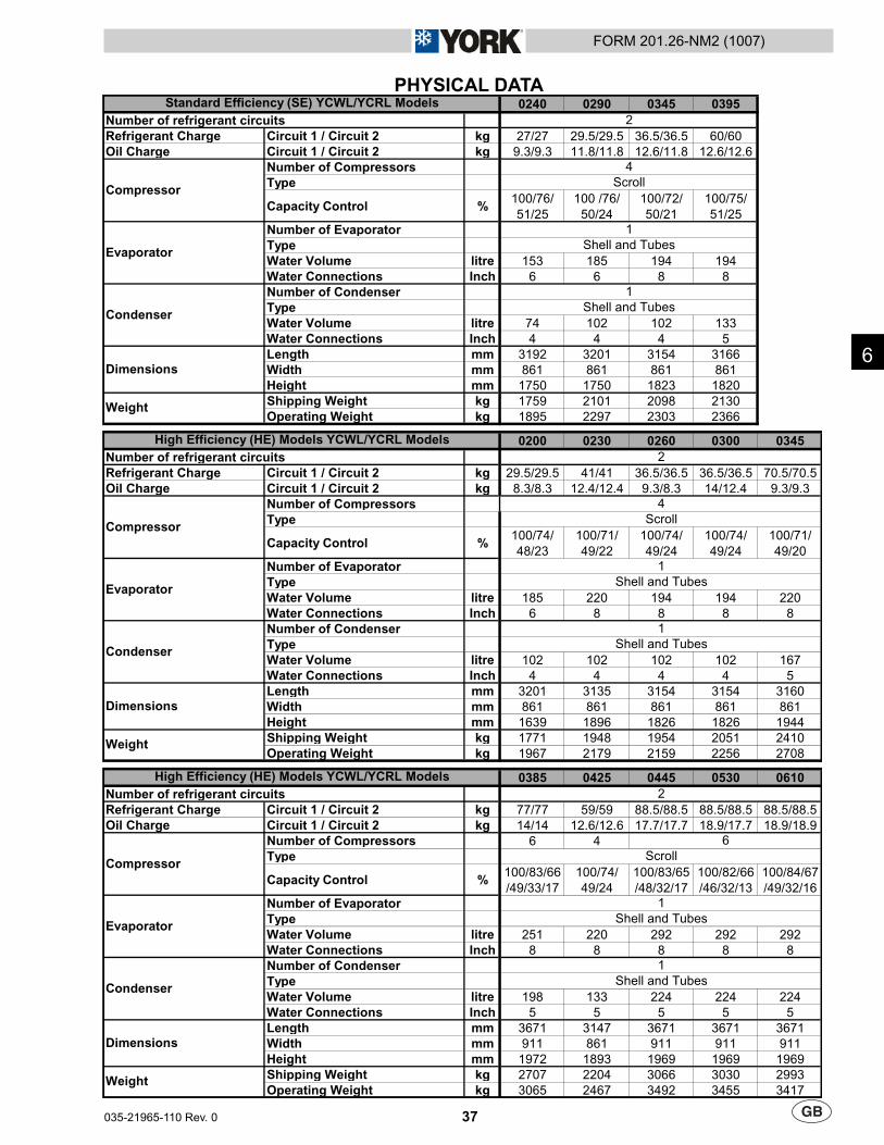
37
FORM 201.26-NM2 (1007)
035-21965-110 Rev. 0
PHYSICAL DATA
6
0240 0290 0345 0395
Number of refrigerant circuits
Refrigerant Charge Circuit 1 / Circuit 2 kg 27/27 29.5/29.5 36.5/36.5 60/60
Oil Charge Circuit 1 / Circuit 2 kg 9.3/9.3 11.8/11.8 12.6/11.8 12.6/12.6
Number of Compressors
Type
Capacity Control %100/76/
51/25
100 /76/
50/24
100/72/
50/21
100/75/
51/25
Number of Evaporator
Type
Water Volume litre 153 185 194 194
Water Connections Inch 6 6 8 8
Number of Condenser
Type
Water Volume litre 74 102 102 133
Water Connections Inch 4 4 4 5
Length mm 3192 3201 3154 3166
Width mm 861 861 861 861
Height mm 1750 1750 1823 1820
Shipping Weight kg 1759 2101 2098 2130
Operating Weight kg 1895 2297 2303 2366
0200 0230 0260 0300 0345
Number of refrigerant circuits
Refrigerant Charge Circuit 1 / Circuit 2 kg 29.5/29.5 41/41 36.5/36.5 36.5/36.5 70.5/70.5
Oil Charge Circuit 1 / Circuit 2 kg 8.3/8.3 12.4/12.4 9.3/8.3 14/12.4 9.3/9.3
Number of Compressors
Type
Capacity Control %100/74/
48/23
100/71/
49/22
100/74/
49/24
100/74/
49/24
100/71/
49/20
Number of Evaporator
Type
Water Volume litre 185 220 194 194 220
Water Connections Inch 6 8 8 8 8
Number of Condenser
Type
Water Volume litre 102 102 102 102 167
Water Connections Inch 4 4 4 4 5
Length mm 3201 3135 3154 3154 3160
Width mm 861 861 861 861 861
Height mm 1639 1896 1826 1826 1944
Shipping Weight kg 1771 1948 1954 2051 2410
Operating Weight kg 1967 2179 2159 2256 2708
0385 0425 0445 0530 0610
Number of refrigerant circuits
Refrigerant Charge Circuit 1 / Circuit 2 kg 77/77 59/59 88.5/88.5 88.5/88.5 88.5/88.5
Oil Charge Circuit 1 / Circuit 2 kg 14/14 12.6/12.6 17.7/17.7 18.9/17.7 18.9/18.9
Number of Compressors 6 4
Type
Capacity Control %100/83/66
/49/33/17
100/74/
49/24
100/83/65
/48/32/17
100/82/66
/46/32/13
100/84/67
/49/32/16
Number of Evaporator
Type
Water Volume litre 251 220 292 292 292
Water Connections Inch 8 8 8 8 8
Number of Condenser
Type
Water Volume litre 198 133 224 224 224
Water Connections Inch 5 5 5 5 5
Length mm 3671 3147 3671 3671 3671
Width mm 911 861 911 911 911
Height mm 1972 1893 1969 1969 1969
Shipping Weight kg 2707 2204 3066 3030 2993
Operating Weight kg 3065 2467 3492 3455 3417
1
Shell and Tubes
Standard Efficiency (SE) YCWL/YCRL Models
High Efficiency (HE) Models YCWL/YCRL Models
High Efficiency (HE) Models YCWL/YCRL Models
2
Scroll
1
Evaporator
Condenser
Dimensions
Weight
2
Scroll
1
Shell and Tubes
1
Shell and Tubes
Shell and Tubes
Compressor
Compressor
Dimensions
Evaporator
Condenser
Weight
2
Weight
Compressor
Evaporator
Dimensions
Condenser
6
4
Scroll
1
Shell and Tubes
1
Shell and Tubes
4
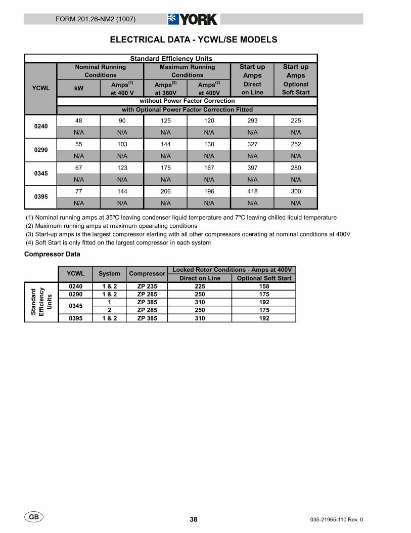
38 035-21965-110 Rev. 0
FORM 201.26-NM2 (1007)
ELECTRICAL DATA - YCWL/SE MODELS
Start up
Amps
Start up
Amps
kWAmps
(1)
at 400 V
Amps(2)
at 360V
Amps(2)
at 400V
Direct
on Line
Optional
Soft Start
48 90 125 120 293 225
N/A N/A N/A N/A N/A N/A
55 103 144 138 327 252
N/A N/A N/A N/A N/A N/A
67 123 175 167 397 280
N/A N/A N/A N/A N/A N/A
77 144 206 196 418 300
N/A N/A N/A N/A N/A N/A
(1) Nominal running amps at 35ºC leaving condenser liquid temperature and 7ºC leaving chilled liquid temperature
(2) Maximum running amps at maximum opearating conditions
(3) Start-up amps is the largest compressor starting with all other compressors operating at nominal conditions at 400V
(4) Soft Start is only fitted on the largest compressor in each system
0395
Standard Efficiency Units
0240
0290
0345
Nominal Running
Conditions
Maximum Running
Conditions
YCWL
without Power Factor Correction
with Optional Power Factor Correction Fitted
Compressor Data
Direct on Line Optional Soft Start
0240 1 & 2 ZP 235 225 158
0290 1 & 2 ZP 285 250 175
1 ZP 385 310 192
2 ZP 285 250 175
0395 1 & 2 ZP 385 310 192
Sta
nd
ard
Eff
icie
nc
y
Un
its
YCWLLocked Rotor Conditions - Amps at 400V
CompressorSystem
0345
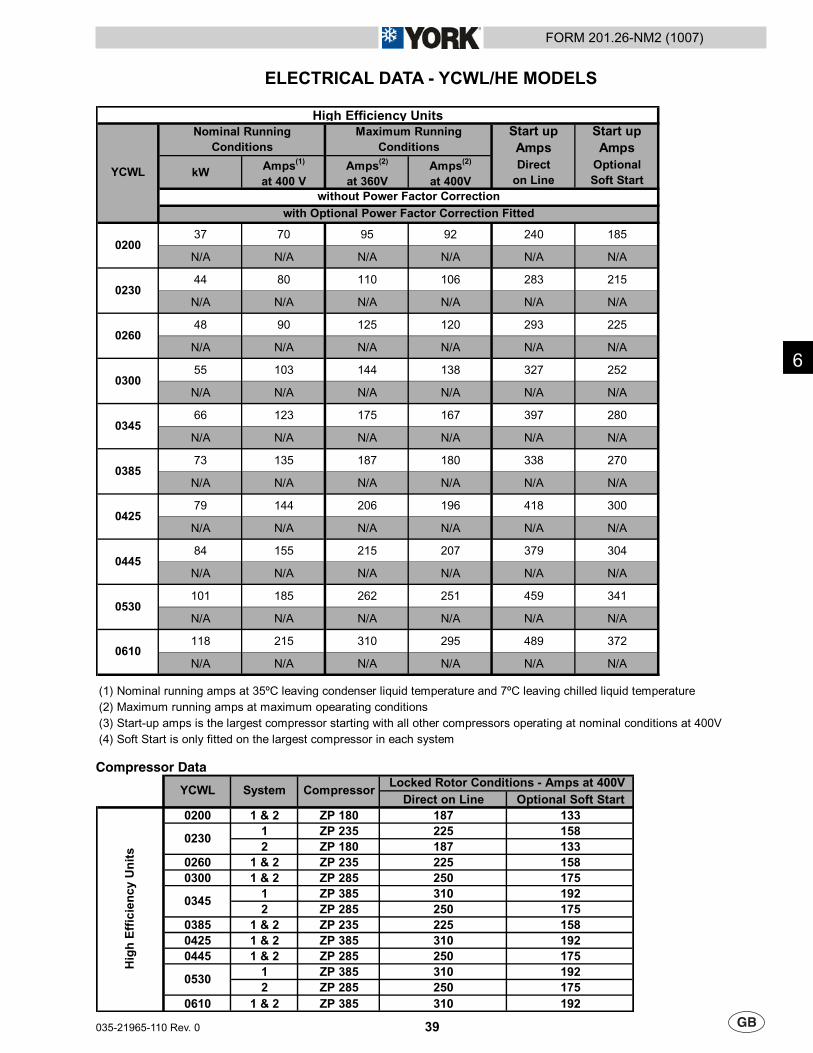
39
FORM 201.26-NM2 (1007)
035-21965-110 Rev. 0
ELECTRICAL DATA - YCWL/HE MODELS
Start up
Amps
Start up
Amps
kWAmps
(1)
at 400 V
Amps(2)
at 360V
Amps(2)
at 400V
Direct
on Line
Optional
Soft Start
37 70 95 92 240 185
N/A N/A N/A N/A N/A N/A
44 80 110 106 283 215
N/A N/A N/A N/A N/A N/A
48 90 125 120 293 225
N/A N/A N/A N/A N/A N/A
55 103 144 138 327 252
N/A N/A N/A N/A N/A N/A
66 123 175 167 397 280
N/A N/A N/A N/A N/A N/A
73 135 187 180 338 270
N/A N/A N/A N/A N/A N/A
79 144 206 196 418 300
N/A N/A N/A N/A N/A N/A
84 155 215 207 379 304
N/A N/A N/A N/A N/A N/A
101 185 262 251 459 341
N/A N/A N/A N/A N/A N/A
118 215 310 295 489 372
N/A N/A N/A N/A N/A N/A
(1) Nominal running amps at 35ºC leaving condenser liquid temperature and 7ºC leaving chilled liquid temperature
(2) Maximum running amps at maximum opearating conditions
(3) Start-up amps is the largest compressor starting with all other compressors operating at nominal conditions at 400V
(4) Soft Start is only fitted on the largest compressor in each system
High Efficiency Units
YCWL
0610
0385
0425
0445
0530
Maximum Running
Conditions
0345
0200
without Power Factor Correction
0260
0300
with Optional Power Factor Correction Fitted
Nominal Running
Conditions
0230
Compressor Data
Direct on Line Optional Soft Start
0200 1 & 2 ZP 180 187 133
1 ZP 235 225 158
2 ZP 180 187 133
0260 1 & 2 ZP 235 225 158
0300 1 & 2 ZP 285 250 175
1 ZP 385 310 192
2 ZP 285 250 175
0385 1 & 2 ZP 235 225 158
0425 1 & 2 ZP 385 310 192
0445 1 & 2 ZP 285 250 175
1 ZP 385 310 192
2 ZP 285 250 175
0610 1 & 2 ZP 385 310 192
YCWL System CompressorLocked Rotor Conditions - Amps at 400V
Hig
h E
ffic
ien
cy
Un
its
0530
0230
0345
6
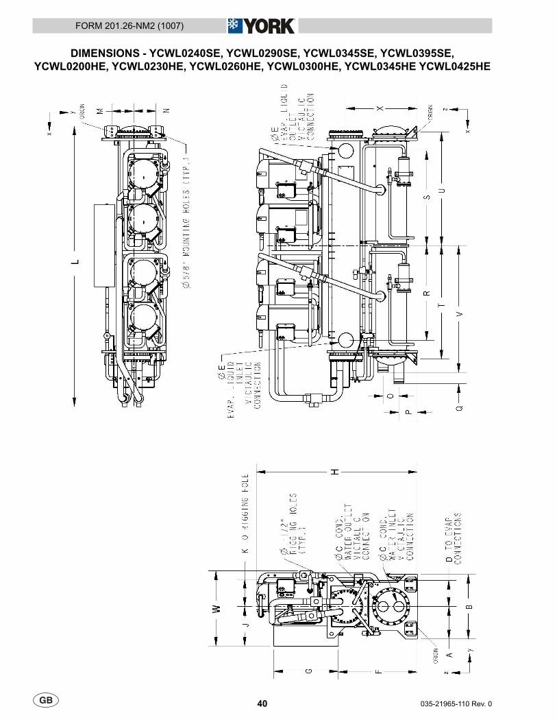
40 035-21965-110 Rev. 0
FORM 201.26-NM2 (1007)
DIMENSIONS - YCWL0240SE, YCWL0290SE, YCWL0345SE, YCWL0395SE,YCWL0200HE, YCWL0230HE, YCWL0260HE, YCWL0300HE, YCWL0345HE YCWL0425HE
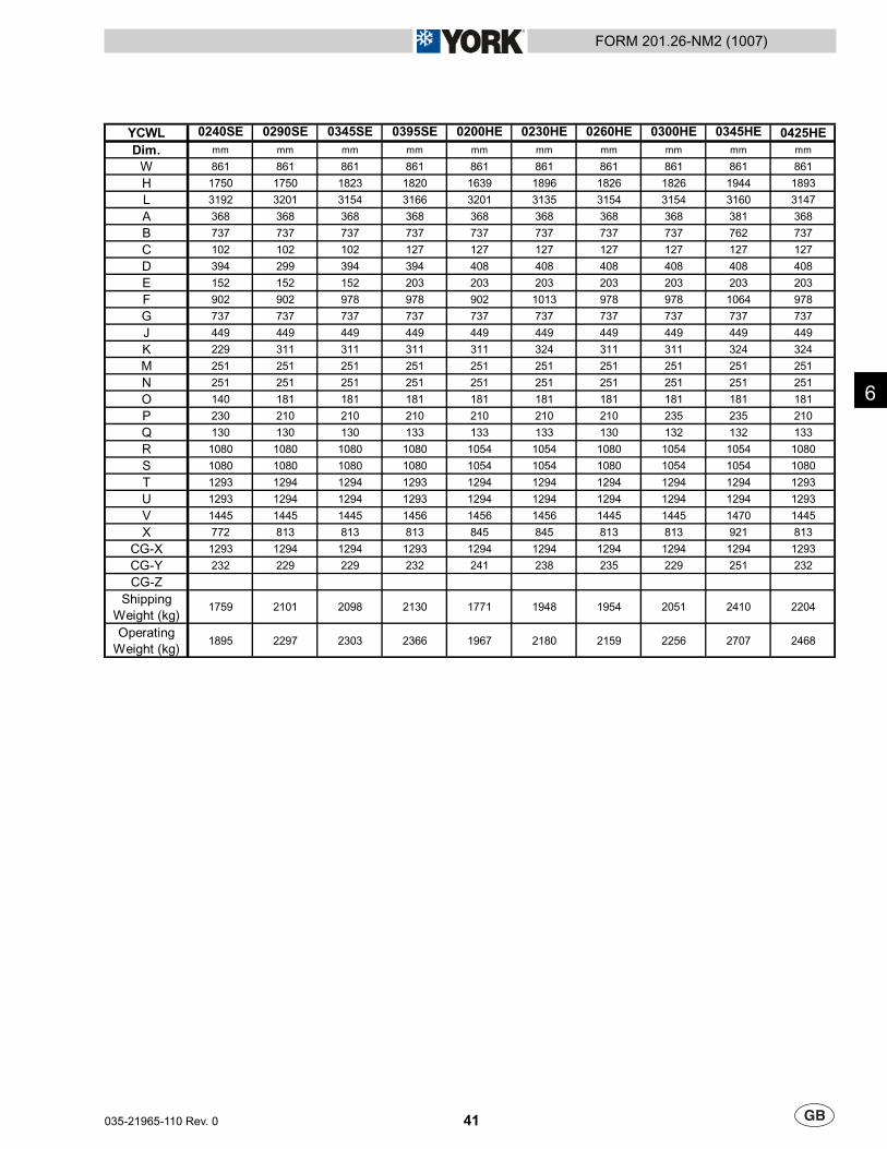
41
FORM 201.26-NM2 (1007)
035-21965-110 Rev. 0
YCWL 0425HE
Dim. mm mm mm mm mm mm mm mm mm mm
W 861 861 861 861 861 861 861 861 861 861
H 1750 1750 1823 1820 1639 1896 1826 1826 1944 1893
L 3192 3201 3154 3166 3201 3135 3154 3154 3160 3147
A 368 368 368 368 368 368 368 368 381 368
B 737 737 737 737 737 737 737 737 762 737
C 102 102 102 127 127 127 127 127 127 127
D 394 299 394 394 408 408 408 408 408 408
E 152 152 152 203 203 203 203 203 203 203
F 902 902 978 978 902 1013 978 978 1064 978
G 737 737 737 737 737 737 737 737 737 737
J 449 449 449 449 449 449 449 449 449 449
K 229 311 311 311 311 324 311 311 324 324
M 251 251 251 251 251 251 251 251 251 251
N 251 251 251 251 251 251 251 251 251 251
O 140 181 181 181 181 181 181 181 181 181
P 230 210 210 210 210 210 210 235 235 210
Q 130 130 130 133 133 133 130 132 132 133
R 1080 1080 1080 1080 1054 1054 1080 1054 1054 1080
S 1080 1080 1080 1080 1054 1054 1080 1054 1054 1080
T 1293 1294 1294 1293 1294 1294 1294 1294 1294 1293
U 1293 1294 1294 1293 1294 1294 1294 1294 1294 1293
V 1445 1445 1445 1456 1456 1456 1445 1445 1470 1445
X 772 813 813 813 845 845 813 813 921 813
CG-X 1293 1294 1294 1293 1294 1294 1294 1294 1294 1293
CG-Y 232 229 229 232 241 238 235 229 251 232
CG-Z
Shipping
Weight (kg)1759 2101 2098 2130 1771 1948 1954 2051 2410 2204
Operating
Weight (kg)1895 2297 2303 2366 1967 2180 2159 2256 2707 2468
0345HE0200HE 0230HE 0260HE 0300HE0240SE 0290SE 0345SE 0395SE
6
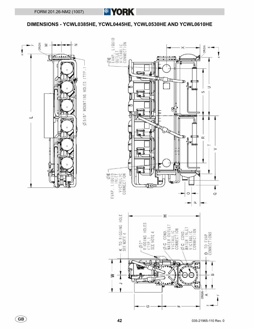
42 035-21965-110 Rev. 0
FORM 201.26-NM2 (1007)
DIMENSIONS - YCWL0385HE, YCWL0445HE, YCWL0530HE AND YCWL0610HE
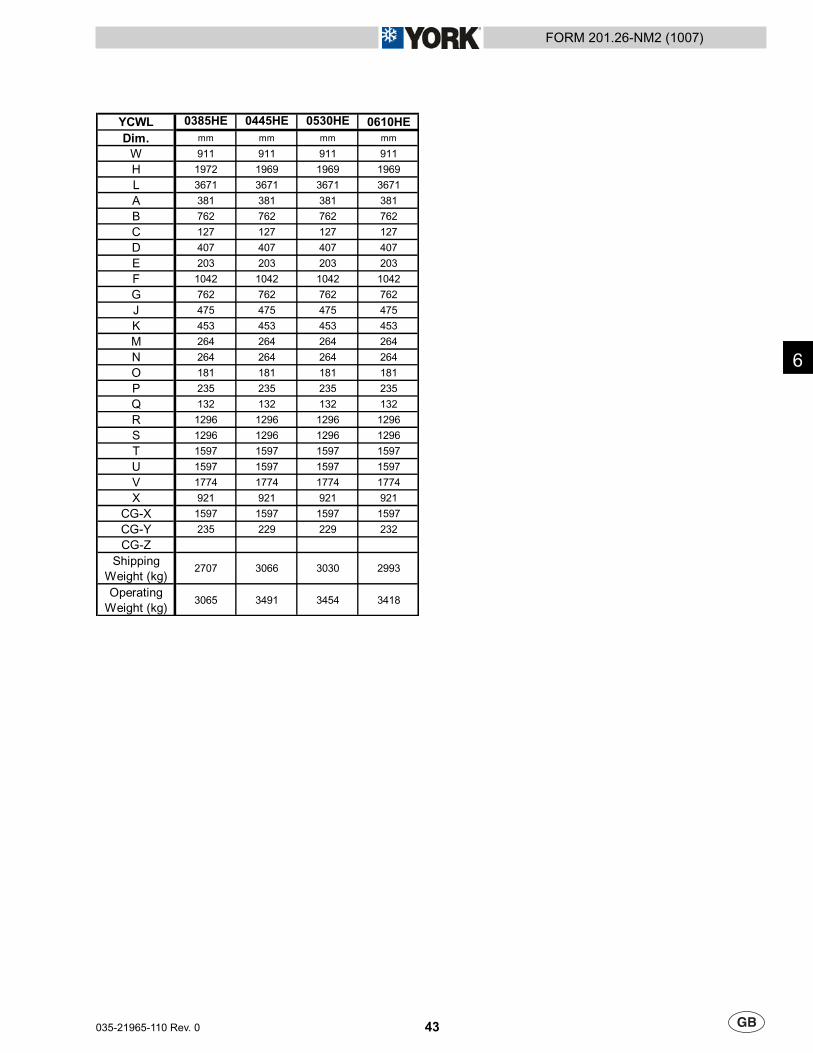
43
FORM 201.26-NM2 (1007)
035-21965-110 Rev. 0
YCWL 0610HE
Dim. mm mm mm mm
W 911 911 911 911
H 1972 1969 1969 1969
L 3671 3671 3671 3671
A 381 381 381 381
B 762 762 762 762
C 127 127 127 127
D 407 407 407 407
E 203 203 203 203
F 1042 1042 1042 1042
G 762 762 762 762
J 475 475 475 475
K 453 453 453 453
M 264 264 264 264
N 264 264 264 264
O 181 181 181 181
P 235 235 235 235
Q 132 132 132 132
R 1296 1296 1296 1296
S 1296 1296 1296 1296
T 1597 1597 1597 1597
U 1597 1597 1597 1597
V 1774 1774 1774 1774
X 921 921 921 921
CG-X 1597 1597 1597 1597
CG-Y 235 229 229 232
CG-Z
Shipping
Weight (kg)2707 3066 3030 2993
Operating
Weight (kg)3065 3491 3454 3418
0385HE 0445HE 0530HE
6
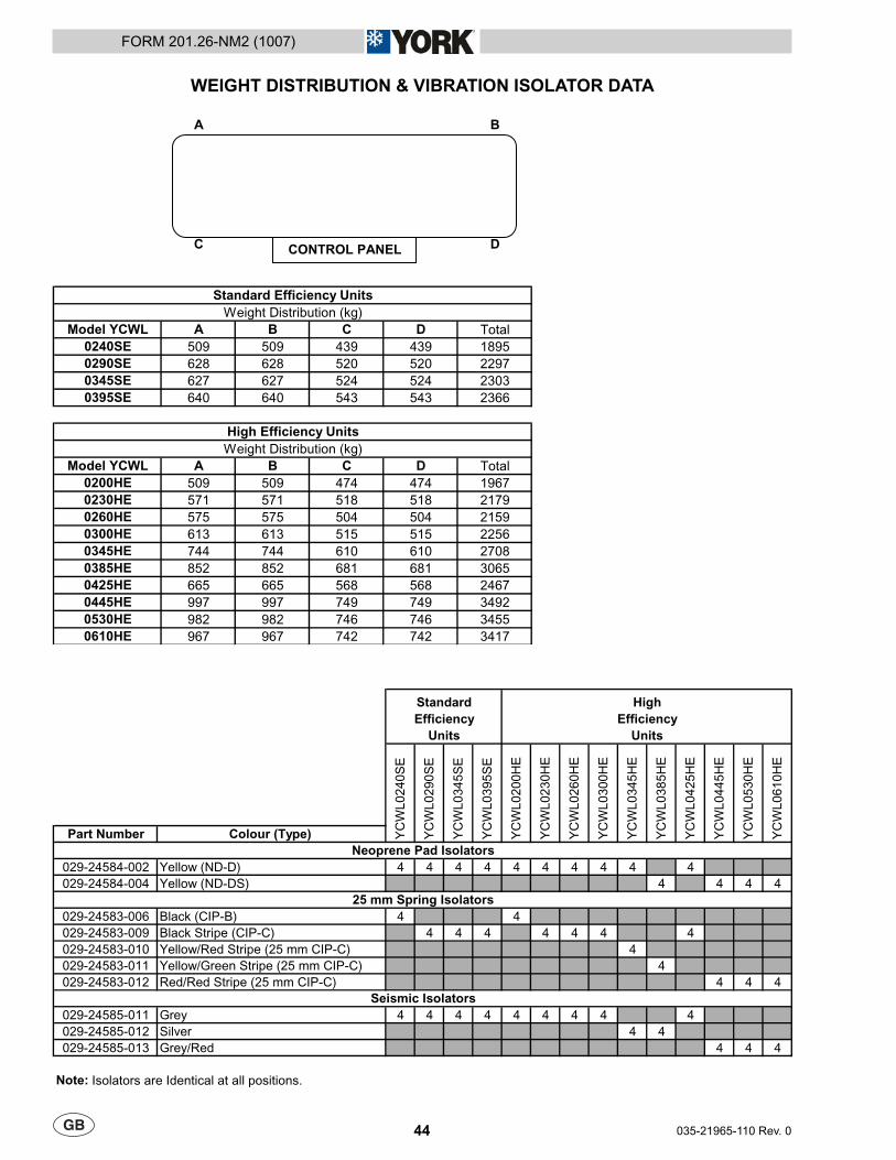
44 035-21965-110 Rev. 0
FORM 201.26-NM2 (1007)
WEIGHT DISTRIBUTION & VIBRATION ISOLATOR DATA
A B
C D
Model YCWL A B C D Total
0240SE 509 509 439 439 1895
0290SE 628 628 520 520 2297
0345SE 627 627 524 524 2303
0395SE 640 640 543 543 2366
Model YCWL A B C D Total
0200HE 509 509 474 474 1967
0230HE 571 571 518 518 2179
0260HE 575 575 504 504 2159
0300HE 613 613 515 515 2256
0345HE 744 744 610 610 2708
0385HE 852 852 681 681 3065
0425HE 665 665 568 568 2467
0445HE 997 997 749 749 3492
0530HE 982 982 746 746 3455
0610HE 967 967 742 742 3417
Standard Efficiency Units
Weight Distribution (kg)
High Efficiency Units
Weight Distribution (kg)
CONTROL PANEL
Part Number Colour (Type)
029-24584-002 Yellow (ND-D) 4 4 4 4 4 4 4 4 4 4
029-24584-004 Yellow (ND-DS) 4 4 4 4
029-24583-006 Black (CIP-B) 4 4
029-24583-009 Black Stripe (CIP-C) 4 4 4 4 4 4 4
029-24583-010 Yellow/Red Stripe (25 mm CIP-C) 4
029-24583-011 Yellow/Green Stripe (25 mm CIP-C) 4
029-24583-012 Red/Red Stripe (25 mm CIP-C) 4 4 4
029-24585-011 Grey 4 4 4 4 4 4 4 4 4
029-24585-012 Silver 4 4
029-24585-013 Grey/Red 4 4 4
Note: Isolators are Identical at all positions.
25 mm Spring Isolators
Seismic Isolators
Neoprene Pad Isolators
YC
WL0260H
E
YC
WL0300H
E
YC
WL0240S
E
YC
WL0290S
E
YC
WL0345S
E
YC
WL0395S
E
YC
WL0530H
E
YC
WL0610H
E
Standard
Efficiency
Units
High
Efficiency
Units
YC
WL0345H
E
YC
WL0385H
E
YC
WL0425H
E
YC
WL0445H
E
YC
WL0200H
E
YC
WL0230H
E
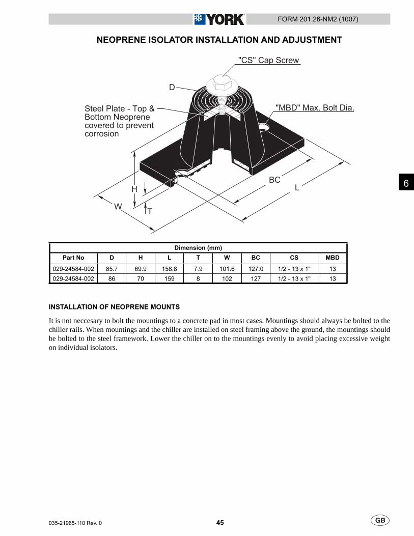
45
FORM 201.26-NM2 (1007)
035-21965-110 Rev. 0
6
"CS" Cap Screw
BC
"MBD" Max. Bolt Dia.Steel Plate - Top &Bottom Neoprenecovered to preventcorrosion
L
T
H
W
D
Dimension (mm)
Part No D H L T W BC CS MBD
029-24584-002 85.7 69.9 158.8 7.9 101.6 127.0 1/2 - 13 x 1" 13
029-24584-002 86 70 159 8 102 127 1/2 - 13 x 1" 13
INSTALLATION OF NEOPRENE MOUNTS
It is not neccesary to bolt the mountings to a concrete pad in most cases. Mountings should always be bolted to the chiller rails. When mountings and the chiller are installed on steel framing above the ground, the mountings should be bolted to the steel framework. Lower the chiller on to the mountings evenly to avoid placing excessive weight on individual isolators.
NEOPRENE ISOLATOR INSTALLATION AND ADJUSTMENT
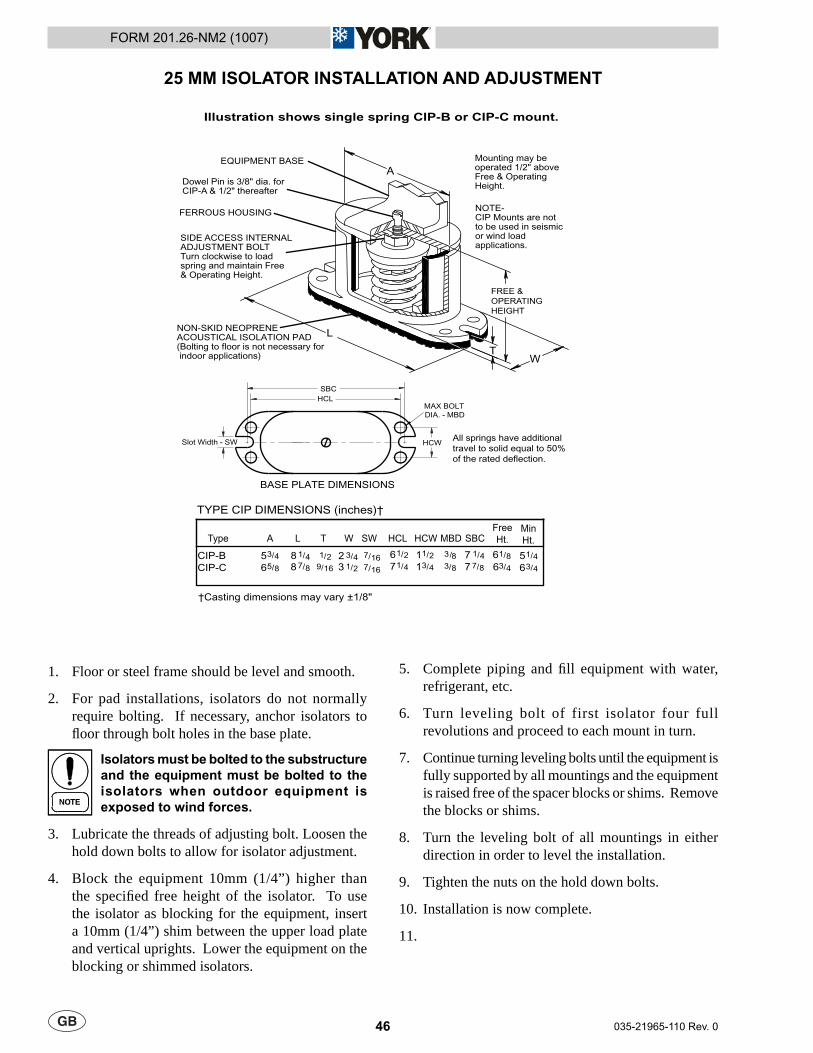
46 035-21965-110 Rev. 0
FORM 201.26-NM2 (1007)
Floor or steel frame should be level and smooth.
For pad installations, isolators do not normally require bolting. If necessary, anchor isolators to fl oor through bolt holes in the base plate.
Isolators must be bolted to the substructure and the equipment must be bolted to the isolators when outdoor equipment is exposed to wind forces.
Lubricate the threads of adjusting bolt. Loosen the hold down bolts to allow for isolator adjustment.
Block the equipment 10mm (1/4”) higher than the specifi ed free height of the isolator. To use the isolator as blocking for the equipment, insert a 10mm (1/4”) shim between the upper load plate and vertical uprights. Lower the equipment on the blocking or shimmed isolators.
1.
2.
3.
4.
Illustration shows single spring CIP-B or CIP-C mount.
HCLSBC
Slot Width - SW HCW
MAX BOLTDIA. - MBD
BASE PLATE DIMENSIONS
NON-SKID NEOPRENEACOUSTICAL ISOLATION PAD(Bolting to floor is not necessary for indoor applications)
All springs have additionaltravel to solid equal to 50%of the rated deflection.
A
L
FREE &OPERATINGHEIGHT
TW
FERROUS HOUSING
SIDE ACCESS INTERNALADJUSTMENT BOLTTurn clockwise to loadspring and maintain Free& Operating Height.
Dowel Pin is 3/8" dia. forCIP-A & 1/2" thereafter
Mounting may beoperated 1/2" aboveFree & OperatingHeight.
NOTE-CIP Mounts are notto be used in seismic or wind loadapplications.
EQUIPMENT BASE
TYPE CIP DIMENSIONS (inches)†
†Casting dimensions may vary ±1/8"
Type A L T W SW HCL HCW MBD SBCFreeHt.
CIP-B 8 /4 /2 /16 8
CIP-C 6 /8 /16 /85
1 1 7
7
3
3/8 1
6 /4 3/5 /43
8 /87 /1692 /43
3 /21
/2/4
1
167
/2/4
1
311
/4/8
1
777
MinHt.
5 /4 1
6 /4 3
6
25 MM ISOLATOR INSTALLATION AND ADJUSTMENT
Complete piping and fi ll equipment with water, refrigerant, etc.
Turn leveling bolt of first isolator four full revolutions and proceed to each mount in turn.
Continue turning leveling bolts until the equipment is fully supported by all mountings and the equipment is raised free of the spacer blocks or shims. Remove the blocks or shims.
Turn the leveling bolt of all mountings in either direction in order to level the installation.
Tighten the nuts on the hold down bolts.
Installation is now complete.
5.
6.
7.
8.
9.
10.
11.
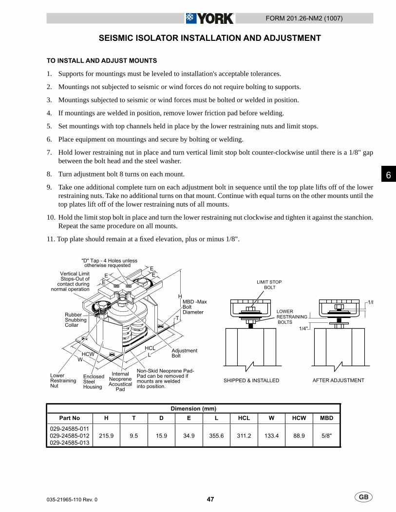
47
FORM 201.26-NM2 (1007)
035-21965-110 Rev. 0
6
SEISMIC ISOLATOR INSTALLATION AND ADJUSTMENT
TO INSTALL AND ADJUST MOUNTS
Supports for mountings must be leveled to installation's acceptable tolerances.
Mountings not subjected to seismic or wind forces do not require bolting to supports.
Mountings subjected to seismic or wind forces must be bolted or welded in position.
If mountings are welded in position, remove lower friction pad before welding.
Set mountings with top channels held in place by the lower restraining nuts and limit stops.
Place equipment on mountings and secure by bolting or welding.
Hold lower restraining nut in place and turn vertical limit stop bolt counter-clockwise until there is a 1/8" gap between the bolt head and the steel washer.
Turn adjustment bolt 8 turns on each mount.
Take one additional complete turn on each adjustment bolt in sequence until the top plate lifts off of the lower restraining nuts. Take no additional turns on that mount. Continue with equal turns on the other mounts until the top plates lift off of the lower restraining nuts of all mounts.
Hold the limit stop bolt in place and turn the lower restraining nut clockwise and tighten it against the stanchion. Repeat the same procedure on all mounts.
11. Top plate should remain at a fi xed elevation, plus or minus 1/8".
1.
2.
3.
4.
5.
6.
7.
8.
9.
10.
SHIPPED & INSTALLED AFTER ADJUSTMENT
1/4"
1/8
LIMIT STOPBOLT
LOWERRESTRAINING BOLTS
EE
EE
H
T
HCWW
LHCL
"D" Tap - 4 Holes unless otherwise requested
AdjustmentBolt
Vertical LimitStops-Out of
contact duringnormal operation
Non-Skid Neoprene Pad-Pad can be removed ifmounts are weldedinto position.
EnclosedSteelHousing
InternalNeopreneAcoustical
Pad
LowerRestrainingNut
RubberSnubbingCollar
MBD -MaxBoltDiameter
Dimension (mm)
Part No H T D E L HCL W HCW MBD
029-24585-011029-24585-012029-24585-013
215.9 9.5 15.9 34.9 355.6 311.2 133.4 88.9 5/8"

48 035-21965-110 Rev. 0
FORM 201.26-NM2 (1007)
This Page Left Intentionally Blank
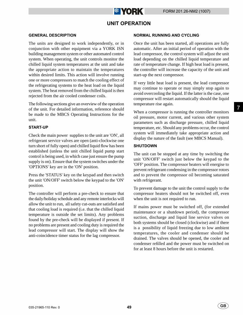
49
FORM 201.26-NM2 (1007)
035-21965-110 Rev. 0
UNIT OPERATION
GENERAL DESCRIPTION
The units are designed to work independently, or in conjunction with other equipment via a YORK ISN building management system or other automated control system. When operating, the unit controls monitor the chilled liquid system temperatures at the unit and take the appropriate action to maintain the temperatures within desired limits. This action will involve running one or more compressors to match the cooling effect of the refrigerating systems to the heat load on the liquid system. The heat removed from the chilled liquid is then rejected from the air cooled condenser coils.
The following sections give an overview of the operation of the unit. For detailed information, reference should be made to the MBCS Operating Instructions for the unit.
START-UP
Check the main power supplies to the unit are 'ON', all refrigerant service valves are open (anti-clockwise one turn short of fully open) and chilled liquid fl ow has been established (unless the unit chilled liquid pump start control is being used, in which case just ensure the pump supply is on). Ensure that the system switches under the 'OPTIONS' key are in the 'ON' position.
Press the 'STATUS' key on the keypad and then switch the unit 'ON/OFF' switch below the keypad to the 'ON' position.
The controller will perform a pre-check to ensure that the daily/holiday schedule and any remote interlocks will allow the unit to run, all safety cut-outs are satisfi ed and that cooling load is required (i.e. that the chilled liquid temperature is outside the set limits). Any problems found by the pre-check will be displayed if present. If no problems are present and cooling duty is required the lead compressor will start. The display will show the anti-coincidence timer status for the lag compressor.
NORMAL RUNNING AND CYCLING
Once the unit has been started, all operations are fully automatic. After an initial period of operation with the lead compressor, the control system will adjust the unit load depending on the chilled liquid temperature and rate of temperature change. If high heat load is present, the controller will increase the capacity of the unit and start-up the next compressor.
If very little heat load is present, the lead compressor may continue to operate or may simply stop again to avoid overcooling the liquid. If the latter is the case, one compressor will restart automatically should the liquid temperature rise again.
When a compressor is running the controller monitors oil pressure, motor current, and various other system parameters such as discharge pressure, chilled liquid temperature, etc. Should any problems occur, the control system will immediately take appropriate action and display the nature of the fault (see MBCS Manual).
SHUTDOWN
The unit can be stopped at any time by switching the unit 'ON/OFF' switch just below the keypad to the 'OFF' position. The compressor heaters will energise to prevent refrigerant condensing in the compressor rotors and to prevent the compressor oil becoming saturated with refrigerant.
To prevent damage to the unit the control supply to the compressor heaters should not be switched off, even when the unit is not required to run.
If mains power must be switched off, (for extended maintenance or a shutdown period), the compressor suction, discharge and liquid line service valves on both systems should be closed (clockwise) and if there is a possibility of liquid freezing due to low ambient temperatures, the cooler and condenser should be drained. The valves should be opened, the cooler and condenser refi lled and the power must be switched on for at least 8 hours before the unit is restarted.
7

50 035-21965-110 Rev. 0
FORM 201.26-NM2 (1007)
This Page Left Intentionally Blank

51
FORM 201.26-NM2 (1007)
035-21965-110 Rev. 0
MAINTENANCE
GENERAL REQUIREMENTS
The units have been designed to operate continuously provided they are regularly maintained and operated within the limitations given in this manual. Each unit should be included in a routine schedule of daily maintenance checks by the operator/customer, backed up by regular service inspection and maintenance visits by a suitably qualifi ed Service Engineer.
It is entirely the responsibility of the owner to provide for these regular maintenance requirements and/or enter into a maintenance agreement with a Johnson Controls service organisation to protect the operation of the unit. If damage or a system failure occurs due to improper maintenance during the warranty period, Johnson Controls shall not be liable for costs incurred to return the unit to satisfactory condition.
This maintenance section applies to the basic unit only and may, on individual contracts, be supplemented by additional requirements to cover any modifi cations or ancillary equipment as applicable.
The Safety Section of this manual should be read carefully before attempting any maintenance operations on the unit. This section should be read in conjunction with the Section 7.
DAILY MAINTENANCE
The following maintenance checks should be carried out on a daily basis by the operator/customer. Please note that the units are not generally user serviceable and no attempt should be made to rectify faults or problems found during daily checks unless competent and equipped to do so. If in any doubt, contact your local Johnson Controls Service Centre.
Unit status: Press the ‘STATUS’ key on the keypad and ensure no fault messages are displayed (refer to the MBCS Manual for explanation of messages and the Trouble Shooting section for courses of action).
Operating conditions: Read the operating pressures and temperatures at the control panel using the ‘OPER DATA’ key and check that these are within the operating limitations given in the MBCS Manual.
Refrigerant leaks: Visually check the cooler, condenser, compressors and pipework for damage and gas leaks.
Compressor oil level: Check the compressor oil level when the compressor is operating normally. The oil level should be between the ½ and ¾ in the oil sight glass.
At shutdown the oil level can fall to the lower limit of the oil sight glass.
Compressor Oil Quality: The oil used in the compressors is pale in colour. If the oil colour darkens or exhibits a change in colour, this may be an indication of contaminants in the refrigerant system. If this occurs, an oil sample should be taken and analysed. If contaminants are present, the system must be cleaned to prevent compressor failure.
Refrigerant Charge: When a system starts up, or sometimes after a change of capacity, a fl ow of bubbles will be seen in the liquid line sight glass. After a few minutes of stable operation, the bubbles should clear leaving just liquid refrigerant showing in the sight glass.
In addition to the checks listed above, periodic inspections of the unit should be carried out to ensure proper equipment operation. Items such as loose equipment, component operation, unusual noises, etc. should be investigated and corrected immediately.
SCHEDULED MAINTENANCE
The maintenance operations detailed in the following table should be carried out on a regular basis by a suitably qualifi ed Service Engineer. It should be noted that the interval necessary between each ‘minor’ and ‘major’ service can vary depending on, for instance, application, site conditions and expected operating schedule. Normally a ‘minor’ service should be carried out every three to six months and a ‘major’ service once a year. It is recommended that your local Johnson Controls Service Centre is contacted for recommendations for individual sites.
8

52 035-21965-110 Rev. 0
FORM 201.26-NM2 (1007)
MAJOR SERVICEAll items under Minor Service plus:
Unit general: Check thermal insulation. Check main structure.Check vibration isolators. Check paint-work.
Refrigerant systems general: Check relief valves. Check solenoid valves.Check for pipework damage.Check for leaks.Check moisture indicator.Check suction superheat.Check liquid subcooling.
Compressors: Check oil level.Check condition of oil.
Evaporator/Condenser: Check water flow. Check water pH / glycol strength.Check water pressure drop.Check heater mats.
Power & Control system general: Check panel condition. Check all connections.Check mains and control wiring. Check compressor contactors.Check sensor locations. Check sensor / transducer calibration.Check mechanical HP cut-outs. Check motor protectors.
Check contactor contacts.Microprocessor controls: Check fault history. Check ambient cut-out function.
Check program settings.Check HP / LP cut-out function’s.Check pump-down function.Check load / unload function.
SERVICE SCHEDULE MINOR SERVICE
Evaporator/Condenser In-Service Inspection
There is no corrosion on the refrigerant side therefore in-service inspection on the refrigerant side is not necessary.
For the water side, if the water used is treated in accordance with Section 4, in-service inspection is not necessary. In the design of the vessels used in the unit, a 1 mm corrosion allowance has been used to consider slight corrosion on the water side. This allowance is suffi cient to cover the lifetime of the unit.
Johnson Controls believes that periodic in service proof testing (e.g.; hydro tests) is not required. However, Johnson Controls recognises that national regulations may require such testing to be conducted.
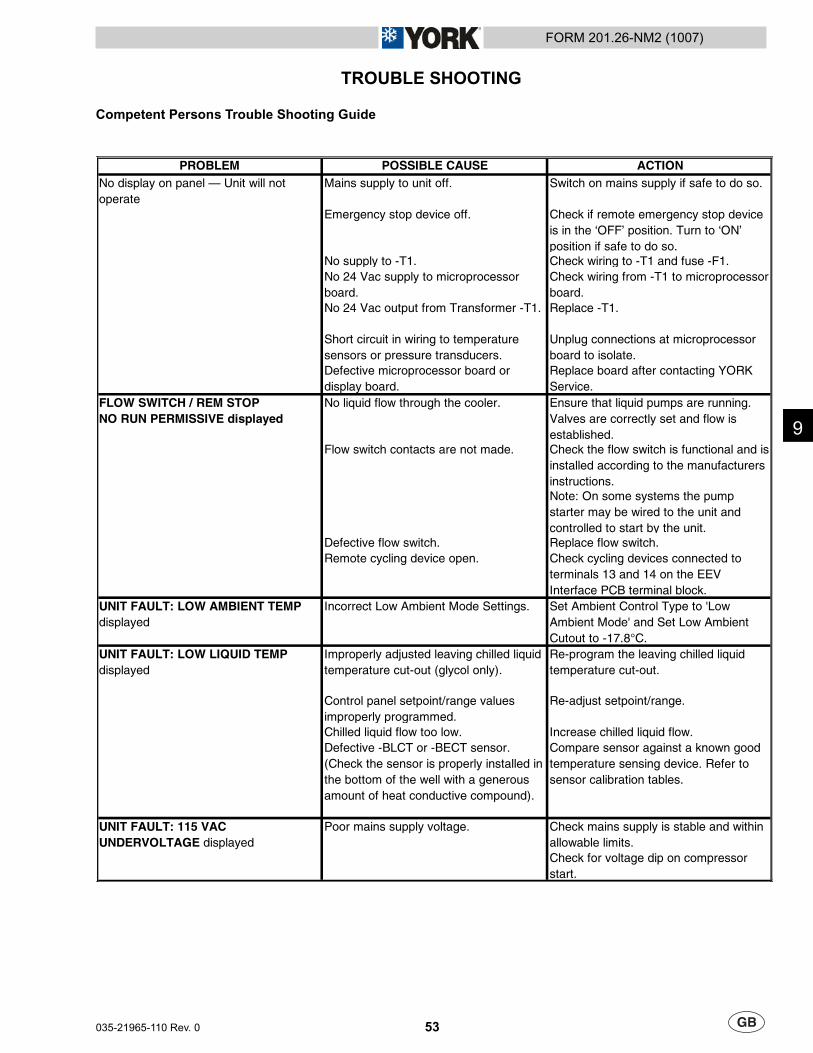
53
FORM 201.26-NM2 (1007)
035-21965-110 Rev. 0
TROUBLE SHOOTING
Competent Persons Trouble Shooting Guide
PROBLEM POSSIBLE CAUSE ACTIONMains supply to unit off. Switch on mains supply if safe to do so.
Emergency stop device off. Check if remote emergency stop device is in the ‘OFF’ position. Turn to ‘ON’ position if safe to do so.
No supply to -T1. Check wiring to -T1 and fuse -F1.No 24 Vac supply to microprocessor board.
Check wiring from -T1 to microprocessor board.
No 24 Vac output from Transformer -T1. Replace -T1.
Short circuit in wiring to temperature sensors or pressure transducers.
Unplug connections at microprocessor board to isolate.
Defective microprocessor board or display board.
Replace board after contacting YORK Service.
FLOW SWITCH / REM STOPNO RUN PERMISSIVE displayed
No liquid flow through the cooler. Ensure that liquid pumps are running. Valves are correctly set and flow is established.
Flow switch contacts are not made. Check the flow switch is functional and is installed according to the manufacturers instructions.Note: On some systems the pump starter may be wired to the unit and controlled to start by the unit.
Defective flow switch. Replace flow switch.Remote cycling device open. Check cycling devices connected to
terminals 13 and 14 on the EEV Interface PCB terminal block.
UNIT FAULT: LOW AMBIENT TEMP displayed
Incorrect Low Ambient Mode Settings. Set Ambient Control Type to 'Low Ambient Mode' and Set Low Ambient Cutout to -17.8°C.
Improperly adjusted leaving chilled liquid temperature cut-out (glycol only).
Re-program the leaving chilled liquid temperature cut-out.
Control panel setpoint/range values improperly programmed.
Re-adjust setpoint/range.
Chilled liquid flow too low. Increase chilled liquid flow.Defective -BLCT or -BECT sensor. (Check the sensor is properly installed in the bottom of the well with a generous amount of heat conductive compound).
Compare sensor against a known good temperature sensing device. Refer to sensor calibration tables.
Check mains supply is stable and within allowable limits.Check for voltage dip on compressor start.
Poor mains supply voltage.
No display on panel — Unit will not operate
UNIT FAULT: LOW LIQUID TEMP displayed
UNIT FAULT: 115 VAC UNDERVOLTAGE displayed
9
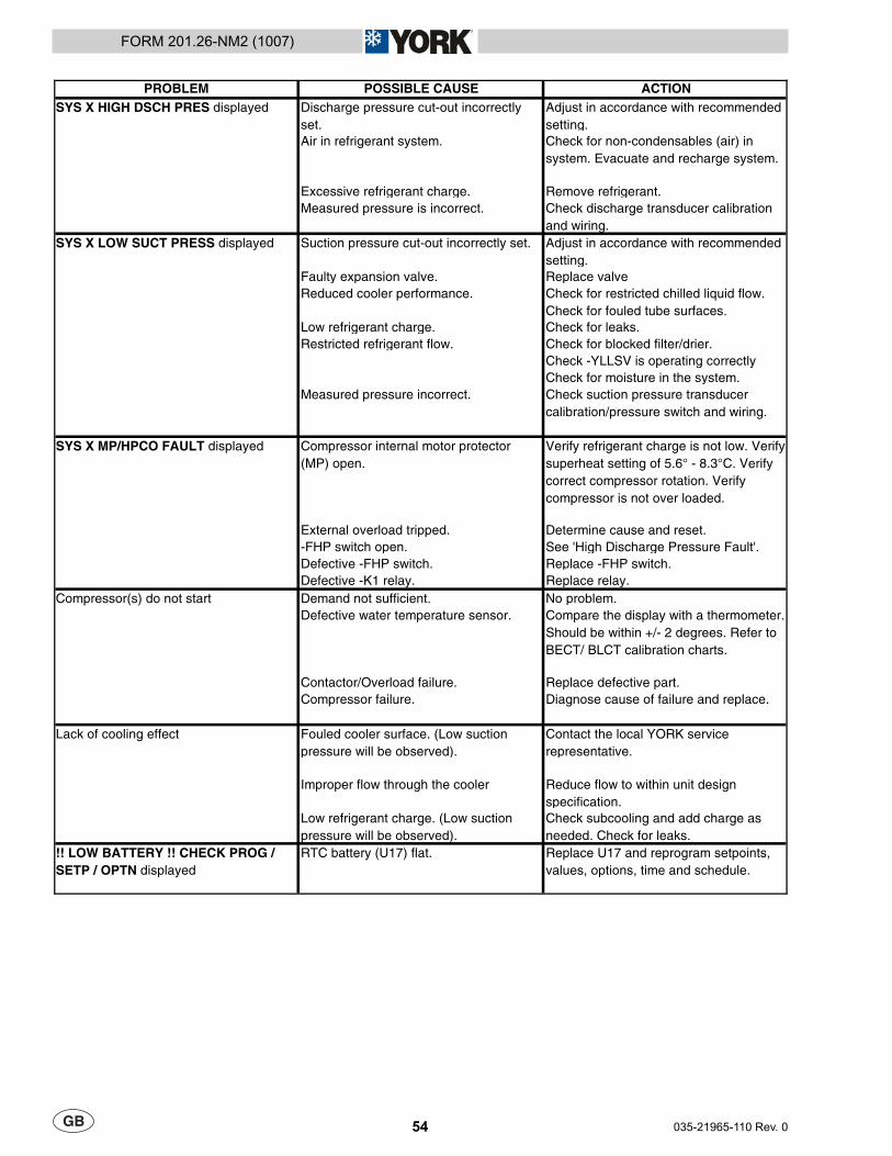
54 035-21965-110 Rev. 0
FORM 201.26-NM2 (1007)
PROBLEM POSSIBLE CAUSE ACTIONDischarge pressure cut-out incorrectly set.
Adjust in accordance with recommended setting.
Air in refrigerant system. Check for non-condensables (air) in system. Evacuate and recharge system.
Excessive refrigerant charge. Remove refrigerant.Measured pressure is incorrect. Check discharge transducer calibration
and wiring.Suction pressure cut-out incorrectly set. Adjust in accordance with recommended
setting.Faulty expansion valve. Replace valveReduced cooler performance. Check for restricted chilled liquid flow.
Check for fouled tube surfaces.Low refrigerant charge. Check for leaks.Restricted refrigerant flow. Check for blocked filter/drier.
Check -YLLSV is operating correctlyCheck for moisture in the system.
Measured pressure incorrect. Check suction pressure transducer calibration/pressure switch and wiring.
Compressor internal motor protector (MP) open.
Verify refrigerant charge is not low. Verify superheat setting of 5.6° - 8.3°C. Verify correct compressor rotation. Verify compressor is not over loaded.
External overload tripped. Determine cause and reset.-FHP switch open. See 'High Discharge Pressure Fault'.Defective -FHP switch. Replace -FHP switch.Defective -K1 relay. Replace relay.Demand not sufficient. No problem.Defective water temperature sensor. Compare the display with a thermometer.
Should be within +/- 2 degrees. Refer to BECT/ BLCT calibration charts.
Contactor/Overload failure. Replace defective part.Compressor failure. Diagnose cause of failure and replace.
Fouled cooler surface. (Low suction pressure will be observed).
Contact the local YORK service representative.
Improper flow through the cooler Reduce flow to within unit design specification.
Low refrigerant charge. (Low suction pressure will be observed).
Check subcooling and add charge as needed. Check for leaks.
!! LOW BATTERY !! CHECK PROG / SETP / OPTN displayed
RTC battery (U17) flat. Replace U17 and reprogram setpoints, values, options, time and schedule.
Compressor(s) do not start
Lack of cooling effect
SYS X HIGH DSCH PRES displayed
SYS X LOW SUCT PRESS displayed
SYS X MP/HPCO FAULT displayed
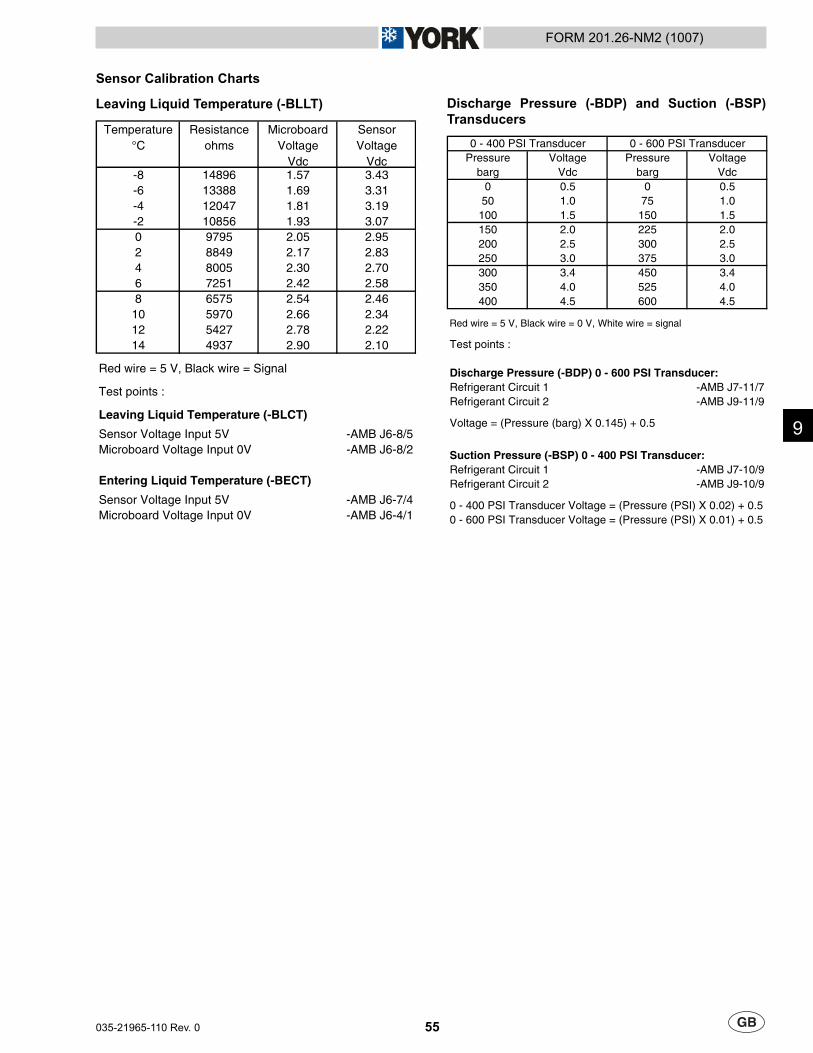
55
FORM 201.26-NM2 (1007)
035-21965-110 Rev. 0
Sensor Calibration Charts
Leaving Liquid Temperature (-BLLT)
Temperature °C
Resistance ohms
MicroboardVoltage
Vdc
Sensor Voltage
Vdc-8 14896 1.57 3.43-6 13388 1.69 3.31-4 12047 1.81 3.19-2 10856 1.93 3.070 9795 2.05 2.952 8849 2.17 2.834 8005 2.30 2.706 7251 2.42 2.588 6575 2.54 2.46
10 5970 2.66 2.3412 5427 2.78 2.2214 4937 2.90 2.10
Red wire = 5 V, Black wire = Signal
Test points :
Leaving Liquid Temperature (-BLCT)
Sensor Voltage Input 5V -AMB J6-8/5Microboard Voltage Input 0V -AMB J6-8/2
Entering Liquid Temperature (-BECT)
Sensor Voltage Input 5V -AMB J6-7/4Microboard Voltage Input 0V -AMB J6-4/1
Discharge Pressure (-BDP) and Suction (-BSP) Transducers
0 - 400 PSI Transducer 0 - 600 PSI TransducerPressure Voltage Pressure Voltage
barg Vdc barg Vdc0 0.5 0 0.5
50 1.0 75 1.0100 1.5 150 1.5150 2.0 225 2.0200 2.5 300 2.5250 3.0 375 3.0300 3.4 450 3.4350 4.0 525 4.0400 4.5 600 4.5
Red wire = 5 V, Black wire = 0 V, White wire = signal
Test points :
Discharge Pressure (-BDP) 0 - 600 PSI Transducer:Refrigerant Circuit 1 -AMB J7-11/7Refrigerant Circuit 2 -AMB J9-11/9
Voltage = (Pressure (barg) X 0.145) + 0.5
Suction Pressure (-BSP) 0 - 400 PSI Transducer:Refrigerant Circuit 1 -AMB J7-10/9Refrigerant Circuit 2 -AMB J9-10/9
0 - 400 PSI Transducer Voltage = (Pressure (PSI) X 0.02) + 0.50 - 600 PSI Transducer Voltage = (Pressure (PSI) X 0.01) + 0.5
9

56 035-21965-110 Rev. 0
FORM 201.26-NM2 (1007)
This Page Left Intentionally Blank
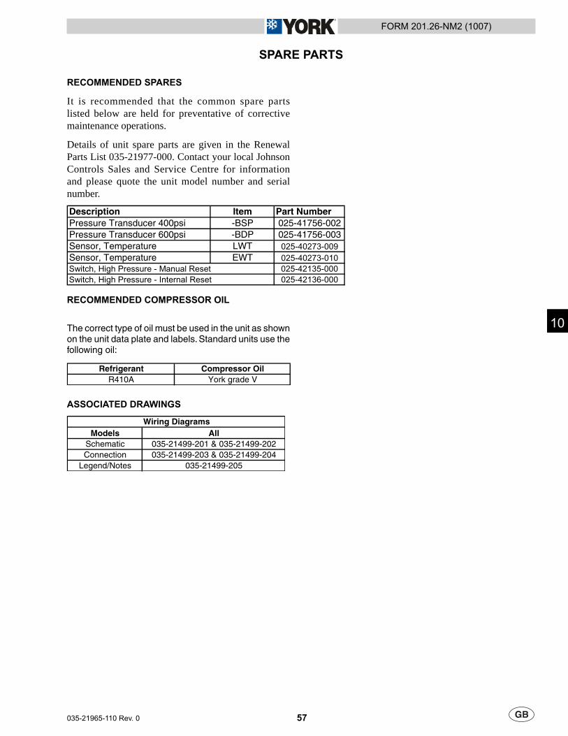
57
FORM 201.26-NM2 (1007)
035-21965-110 Rev. 0
SPARE PARTS
RECOMMENDED SPARES
It is recommended that the common spare parts listed below are held for preventative of corrective maintenance operations.
Details of unit spare parts are given in the Renewal Parts List 035-21977-000. Contact your local Johnson Controls Sales and Service Centre for information and please quote the unit model number and serial number.
Description Item Part NumberPressure Transducer 400psi -BSP 025-41756-002Pressure Transducer 600psi -BDP 025-41756-003Sensor, Temperature LWT 025-40273-009
Sensor, Temperature EWT 025-40273-010
Switch, High Pressure - Manual Reset 025-42135-000
Switch, High Pressure - Internal Reset 025-42136-000
RECOMMENDED COMPRESSOR OIL
The correct type of oil must be used in the unit as shown on the unit data plate and labels. Standard units use the following oil:
Refrigerant Compressor OilR410A York grade V
ASSOCIATED DRAWINGS
Models AllSchematic 035-21499-201 & 035-21499-202Connection 035-21499-203 & 035-21499-204
Legend/Notes 035-21499-205
Wiring Diagrams
10

58 035-21965-110 Rev. 0
FORM 201.26-NM2 (1007)
This Page Left Intentionally Blank
59
FORM 201.26-NM2 (1007)
035-21965-110 Rev. 0
DECOMMISSIONING. DISMANTLING AND DISPOSALNever release refrigerant to the atmosphere when emptying the refrigerating circuits. Suitable retrieval equipment must be used. If reclaimed refrigerant cannot be reused. It must be returned to the manufacturer.
Never discard used compressor oil, as it contains refrigerant in solution. Return used oil to the oil manufacturer.
Unless otherwise indicated, the operations described below can be performed by any properly trained maintenance technician.
GENERAL
Isolate all sources of electrical supply to the unit including any control system supplies switched by the unit. Ensure that all points of isolation are secured in the ‘OFF’ position. The supply cables may then be disconnected and removed. For connection points refer to Section 4.
Remove all refrigerant from each system of the unit into a suitable container using a refrigerant reclaim or recovery unit. This refrigerant may then be re-used, if appropriate, or returned to the manufacturer for disposal. Under NO circumstances should refrigerant be vented to atmosphere. Drain the refrigerant oil from each system into a suitable container and dispose of according to local laws and regulations governing the disposal of oily wastes. Any spilt oil should be mopped up and similarly disposed of.
Isolate the unit heat exchanger from the external water systems and drain the heat exchanger section of the system. If no isolation valves are installed it may be necessary to drain the complete system.
If glycol or similar solutions have been used in the water system, or chemical additives are contained, the solution MUST be disposed of in a suitable and safe manner. Under NO circumstances should any system containing glycol or similar solutions be drained directly into domestic waste or natural water systems.
After draining, the water pipework may be disconnected and removed.
Packaged units can generally be removed in one piece after disconnection as above. Any fi xing down bolts should be removed and then the unit should be lifted from position using the points provided and equipment of adequate lifting capacity.
Reference should be made to Section 4 for unit installation instructions, Section 9 for unit weights and Section 3 for handling.
Units which cannot be removed in one piece after disconnection as above must be dismantled in position. Special care should be taken regarding the weight and handling of each component. Where possible units should be dismantled in the reverse order of installation.
Residual refrigerant oil and glycol or similar solutions may remain in some parts of the system. These should be mopped up and disposed of as described above.
It is important to ensure that whilst components are being removed the remaining parts are supported in a safe manner.
Only use lifting equipment of adequate capacity.
After removal from position the unit parts may be disposed of according to local laws and regulations.
11

FORM 201.26-NM2 (1007)
Form 201.26-NM2 (1007) Subject to change without notice. (Part No.035-21965-110) Revision 0 ALL RIGHTS RESERVED