YAWL - Technical Manual · YAWL - Technical Manual Version 2.1 ... 1.3 The YAWL Foundation ......
100
YAWL - Technical Manual Version 2.1 © 2010 The YAWL Foundation
Transcript of YAWL - Technical Manual · YAWL - Technical Manual Version 2.1 ... 1.3 The YAWL Foundation ......

YAWL - Technical ManualVersion 2.1
© 2010 The YAWL Foundation

Page 2 of 100

Contents
1 Introduction 7
1.1 What is YAWL? . . . . . . . . . . . . . . . . . . . . . . . . . . . . . . . . . . . . . . . . . . . 7
1.2 Obtaining the Latest Version of YAWL . . . . . . . . . . . . . . . . . . . . . . . . . . . . . . . 8
1.3 The YAWL Foundation . . . . . . . . . . . . . . . . . . . . . . . . . . . . . . . . . . . . . . . 8
1.4 Documentation . . . . . . . . . . . . . . . . . . . . . . . . . . . . . . . . . . . . . . . . . . . . 8
2 Installation 11
2.1 Requirements . . . . . . . . . . . . . . . . . . . . . . . . . . . . . . . . . . . . . . . . . . . . . 11
2.2 Installation Environment . . . . . . . . . . . . . . . . . . . . . . . . . . . . . . . . . . . . . . . 12
2.3 Known Issues . . . . . . . . . . . . . . . . . . . . . . . . . . . . . . . . . . . . . . . . . . . . . 12
3 The Main Engine Classes 13
3.1 Elements Package [org.yawlfoundation.yawl.elements] . . . . . . . . . . . . . . . . . . . 13
3.2 State Package [org.yawlfoundation.yawl.elements.state] . . . . . . . . . . . . . . . . . 14
3.3 Engine Package [org.yawlfoundation.yawl.engine] . . . . . . . . . . . . . . . . . . . . . . 14
4 YAWL Custom Services: Creation and Deployment 15
4.1 Fundamentals . . . . . . . . . . . . . . . . . . . . . . . . . . . . . . . . . . . . . . . . . . . . . 15
4.2 A Simple Custom Service . . . . . . . . . . . . . . . . . . . . . . . . . . . . . . . . . . . . . . 19
4.3 Deployment . . . . . . . . . . . . . . . . . . . . . . . . . . . . . . . . . . . . . . . . . . . . . . 25
4.4 Additional Topics . . . . . . . . . . . . . . . . . . . . . . . . . . . . . . . . . . . . . . . . . . . 30
4.5 Other Engine Interfaces . . . . . . . . . . . . . . . . . . . . . . . . . . . . . . . . . . . . . . . 34
5 Implementing In-Process Custom Services 45
5.1 Introduction . . . . . . . . . . . . . . . . . . . . . . . . . . . . . . . . . . . . . . . . . . . . . . 45
5.2 The InterfaceB Observer Gateway . . . . . . . . . . . . . . . . . . . . . . . . . . . . . . . . . 46
5.3 Interface Design . . . . . . . . . . . . . . . . . . . . . . . . . . . . . . . . . . . . . . . . . . . . 46
5.4 Custom Service URLs . . . . . . . . . . . . . . . . . . . . . . . . . . . . . . . . . . . . . . . . 47
5.5 Implementing the Manager Class . . . . . . . . . . . . . . . . . . . . . . . . . . . . . . . . . . 48
5.6 Registering with the YAWL Engine . . . . . . . . . . . . . . . . . . . . . . . . . . . . . . . . . 51
6 The Resource Service 53
7 The Worklet Service 55
3

8 The Editor 57
8.1 Introduction . . . . . . . . . . . . . . . . . . . . . . . . . . . . . . . . . . . . . . . . . . . . . . 57
8.2 Foundations . . . . . . . . . . . . . . . . . . . . . . . . . . . . . . . . . . . . . . . . . . . . . . 57
8.3 Superstructure . . . . . . . . . . . . . . . . . . . . . . . . . . . . . . . . . . . . . . . . . . . . 67
8.4 Future Considerations . . . . . . . . . . . . . . . . . . . . . . . . . . . . . . . . . . . . . . . . 73
A Third Party Software Acknowledgements 75
B newYAWL Resource Perspective Requirements Analysis 77
B.1 Introduction . . . . . . . . . . . . . . . . . . . . . . . . . . . . . . . . . . . . . . . . . . . . . . 77
B.2 Requirements . . . . . . . . . . . . . . . . . . . . . . . . . . . . . . . . . . . . . . . . . . . . . 78
Page 4 of 100

Document Control
Arthur ter Hofstede version 1.9 September 2008 Consolidation of ten previous documents,conversion to LATEX of nine of them,general cleaning and extensions.
Stephan Clemens version 1.91 September 2008 Input for installation section.
Michael Adams version 2.1 August 2010 Major rewrite and upgrade for 2.1.First public release of manual.
Original Sources
The first version of this document (1.9) combined the following earlier documents:
1. A “Connecting Custom Services to the YAWL Engine” (Beta 7 Release) document by Marlon Dumas,Tore Fjellheim and Lachlan Aldred. This document has been entirely replaced by Chapter 4, writtenby Michael Adams.
2. A “YAWL Core Classes Cheat Sheet - A Short Architectural Introduction” (Beta 7 Release) by LachlanAldred. This forms the basis for Chapter 3.
3. A “Implementing In-Process Custom Services” document created by Andrew Hastie, subsequentlyreviewed and refined by Lachlan Aldred, and later refined and updated by Michael Adams. This formsthe basis for Chapter 5.
4. A “YAWL - Time Service Manual” (Beta 7 Release) document first created by Sean Kneipp with laterupdates by Tore Fjellheim and Lachlan Aldred. The Time Service has since been deprecated and sothis document has been removed from the manual.
5. An “Installation Manual” (Engine Beta 8.2 - Editor 1.5) first created by Sean Kneipp and with subse-quent changes/corrections/extensions by Guy Redding, Lachlan Aldred, Petia Wohed, Michael Adams,Moe Wynn, and Marcello La Rosa. An extract forms the basis for Chapter 2 (a large part was trans-ferred to the User Manual). Its introduction forms the basis for Chapter 1.
6. A document on Interface B first created by Michael Adams with a later addition by Tore Fjellheim.Parts of the document have been folded into Chapter 4.
7. A document on Interface D created by Guy Redding. Interface D has since been deprecated and sothis document has been removed from the manual.
8. A document on Interface X created by Michael Adams. This forms the basis for Section 4.5.3 ofChapter 4.
9. A “YAWLEditor Technical Manual” created by Lindsay Bradford. This document was modified byMichael Adams and became Chapter 8.
5

10. A “newYAWL Resource Perspective Requirements Analysis” document created by Lindsay Bradford.This document was copied into Appendix B.
Page 6 of 100

Chapter 1
Introduction
This chapter provides a brief background introduction to YAWL and the YAWL Foundation.
1.1 What is YAWL?
Based on a rigourous analysis of existing workflow management systems and workflow languages, a newworkflow language called YAWL (Yet Another Workflow Language) was developed by Wil van der Aalst(Eindhoven University of Technology, the Netherlands) and Arthur ter Hofstede (Queensland University ofTechnology, Australia) in 2002. This language was based on the one hand on Petri nets, a well-establishedconcurrency theory with a graphical representation, and on the other hand on the well-known WorkflowPatterns (www.workflowpatterns.com). The Workflow Patterns form a generally accepted benchmark forthe suitability of a process specification language. Petri nets can capture quite a few of the identifiedcontrol-flow patterns, but they lack support for the multiple instance patterns, the cancellation patterns andthe generalised OR-join. YAWL therefore extends Petri nets with dedicated constructs to deal with thesepatterns.
YAWL offers the following distinctive features:
• YAWL offers comprehensive support for the control-flow patterns. It is the most powerful processspecification language for capturing control-flow dependencies.
• The data perspective in YAWL is captured through the use of XML Schema, XPath and XQuery.
• YAWL offers comprehensive support for the resource patterns. It is the most powerful process specifi-cation language for capturing resourcing requirements.
• YAWL has a proper formal foundation. This makes its specifications unambiguous and automatedverification becomes possible (YAWL offers two distinct approaches to verification, one based on Resetnets, the other based on transition invariants through the WofYAWL editor plug-in).
• YAWL has been developed independent from any commercial interests. It simply aims to be the mostpowerful language for process specification.
• For its expressiveness, YAWL offers relatively few constructs (compare this e.g. to BPMN!).
• YAWL offers unique support for exceptional handling, both those that were and those that were notanticipated at design time.
• YAWL offers unique support for dynamic workflow through the Worklets approach. Workflows canthus evolve over time to meet new and changing requirements.
7

• YAWL aims to be straightforward to deploy. It offers a number of automatic installers and an intuitivegraphical design environment.
• Through the BPMN2YAWL component, BPMN models can be mapped to the YAWL environment forexecution.
• The Declare component (released through declare.sf.net) provides unique support for specifyingworkflows in terms of constraints. This approach can be combined with the Worklet approach thusproviding very powerful flexibility support.
• YAWL’s architecture is Service-oriented and hence one can replace existing components with one’s ownor extend the environment with newly developed components.
• The YAWL environments supports the automated generation of forms. This is particularly useful forrapid prototyping purposes.
• Tasks in YAWL can be mapped to human participants, Web Services, external applications or to Javaclasses.
• Through the C-YAWL approach a theory has been developed for the configuration of YAWL models.For more information on process configuration visit www.processconfiguration.com.
• Simulation support is offered through a link with the ProM (www.processmining.org) environment.Through this environment it is also possible to conduct post-execution analysis of YAWL processes(e.g. in order to identify bottlenecks).
1.2 Obtaining the Latest Version of YAWL
As new versions of the YAWL Environment are released to the public, they will be available for downloadat the YAWL Sourceforge website (sourceforge.net/projects/yawl). From this site it is also possible toaccess the source code of all components for development purposes.
1.3 The YAWL Foundation
For up-to-the-minute information on any aspect of the YAWL Initiative, visit the YAWL Foundation Home-page (yawlfoundation.org). The YAWL Foundation is a non-profit organisation that acts as custodian ofall intellectual property (IP) related to YAWL and its support environment.
1.4 Documentation
Apart from this technicial manual, there is a user manual on YAWL and a number of case studies. Thesestudies provide detailed examples that you may wish to consult in order to obtain a deeper understandingof the application of YAWL.
This manual does not really cover the control-flow concepts of YAWL in detail. One reason for this is thatthere are quite a few papers out there that do provide this information. We refer the reader to e.g. [4]for a justification of the extensions of Petri nets introduced for YAWL on the basis of the original control-flow patterns. The main paper on YAWL, from a language point of view, is [5]. In this paper you finda formalisation of the control-flow concepts of YAWL. More recently, a CPN formalisation of newYAWL(control-flow, data and resource perspectives) was presented in [17]. For a formalisation of the OR-join, acomplex synchronisation concept in YAWL, we refer to [21]. This definition supersedes the definition providedin [5].
Page 8 of 100

As mentioned above, YAWL extends Petri nets. There are a number of general introductions to Petri netsin the literature. We refer the interested reader to [13, 11].
Wil van der Aalst has written much about the application of Petri nets to workflow, see e.g. [1]. The subclassof Petri nets introduced by him, Workflow-nets, is a predecessor of YAWL. The textbook that he wrotetogether with Kees van Hee is highly recommended reading [3].
A recent textbook on Business Process Management (BPM), which covers the original control-flow patternsand also YAWL, was written by Mathias Weske [19]. This textbook also covers other approaches, such as themodelling standard BPMN (note that the BPMN2YAWL tool can convert these specifications to YAWL).
On the YAWL web site (yawlfoundation.org) it can be seen how the original control-flow patterns canbe realised in YAWL (follow the link on Resources and then click ‘patterns’). For control-flow patterns innewYAWL the reader can consult appendix A.1 of Nick Russell’s PhD thesis [17].
If you would like to know more about how verification of YAWL specifications really works, we refer youto [18] and to [20]. This work forms the theoretical basis of how the verification mechanisms are realised inthe YAWL editor.
In-depth discussion of YAWL’s exception handling framework from a conceptual point of view can be foundin [17, 15] and from an implementation aspect in [6, 7]. YAWL’s worklet approach to dealing with on-the-flychanges to workflows is discussed in [6, 8].
The reader that is interested in declarative specification of workflow is referred to [12]. On the Declare website, declare.sf.net, the Declare service for YAWL can be downloaded. Further documentation about thisapproach can also be found there.
YAWL has a close link to the Process Mining environment ProM [2], www.processmining.org. This link isfor example exploited in [14] to provide simulation support for YAWL. There exists support for exportingYAWL logs to ProM which can subsequently be analysed by one of the many mining plug-ins available inthis environment.
Alternative ways of presenting work lists have been addressed in [9]. In this Visualiser framework users canchoose a map (not just a geographical map, but also e.g. a timeline or a YAWL specification) and work itemscan be positioned on this map and be shown in a colour that reflects their level of urgency (a context-specificnotion which can be defined for the user). Support for the visualiser framework is provided via the defaultYAWL worklist handler.
Finally, a textbook on YAWL, called Modern Business Process Automation: YAWL and its Support Envi-ronment has been published by Springer (2010; ISBN: 978-3-642-03120-5) [10]. The book provides a com-prehensive treatment of the field of Business Process Management (BPM) with a focus on Business ProcessAutomation. It achieves this by covering a wide range of topics, both introductory and advanced, illustratedthrough and grounded in the YAWL language and support environment.
Page 9 of 100

Page 10 of 100

Chapter 2
Installation
This chapter provides a brief overview of the various YAWL installation methods. Please refer to Chapter 2of the YAWL User Manual for detailed installation instructions.
There are a number of installer tools that allow you to start working with YAWL quickly:
• YAWL4Study is available for Windows, Linux and OSX. This is the installer to choose if YAWL isused within a single user (or small group) environment. For example, your personal need might be towrite a workflow research paper based on YAWL or to prepare your next workflow lecture. FurthermoreYAWL4Study is the right choice if you intend to learn about or to experiment with YAWL. The resultinginstallation will have full functionality and contains the same YAWL components as YAWL4Enterprise.It is just that it assumes use on a single machine with little configuration effort and so is not suitableas a server installation.
• YAWL4Enterprise is available for Windows only (other OSs can install the Enterprise version manually).The installer will install Apache Tomcat (if it is not already installed) and, by default, PostgreSQLas its supporting database system (if it is not already installed), although different database systemsmay also be configured for use.. Third-party components like Tomcat and PostgreSQL are installed asservices so that YAWL can be used as a long-running server for production purposes. Furthermore, theinstaller allows for the configuration of the YAWL environment. For production purposes this is theinstaller to use.
• YAWLive is a LiveCD which contains a Linux operating system and a fully pre-configured YAWLenvironment. No installation is required, all that needs to be done is to boot the .iso image from avirtual machine or a previously burned YAWLive CDROM. This is a great way to use YAWL in aneducational setting.
A manual installation is also possible, by means of the distribution files archive.
2.1 Requirements
YAWL4Study for Linux requires the Java SE Runtime Environment (JRE), 1.5.0-0 or greater (java.sun.com). Furthermore, xdg-utils (portland.freedesktop.org) should be installed and be supported by yourdesktop environment (GNOME and KDE do support xdg-utils) to visualise YAWL menu entries.
YAWLive works on any computer as long as it is started in a virtual machine (i.e. VirtualBox or VMware).In contrast, a burned YAWLive CDROM may freeze the computer during boot phase, depending on theactual hardware used.
For manual installation using the distribution files, the following requirements hold:
• Java SE Runtime Environment (JRE), 1.5.0-0 or greater (java.sun.com)
11

• Apache Tomcat, 5.5.26 or greater (http://jakarta.apache.org/tomcat)
• PostgreSQL, 8.0 or greater (www.postgresql.org), or any other database system known to be sup-ported by Hibernate (see community.jboss.org/wiki/SupportedDatabases for details).
YAWL 2.0 has been tested under
• Windows: XP and later;
• Linux: Ubuntu (Hardy Heron), sidux (KDE), Debian (Etch) and later;
• OSX: 10.4 (Tiger) and later.
2.2 Installation Environment
Essentially, the only differences between the Study and Enterprise versions is that (i) Study comes completewith a pre-built and pre-configured Apache Derby database, while the Enterprise version uses a databasesystem chosen by the person doing the installation (or PostgreSQL by default); and (ii) Study installs aversion of Tomcat for its own use, while the Enterprise version installs Tomcat for system-wide use (or usesan existing installation of Tomcat if available). This allows pre-existing Tomcat and database installationsto be used, if desired. On startup, YAWL checks the existence of all required database tables, and (re)buildsany that are missing.
For a YAWL4Study installation, Tomcat is located in the directory yawl installation path/engine/ and theDerby database in yawl installation path/engine/databases/yawldb.
In contrast, YAWL4Enterprise treats third-party components Apache Tomcat and PostgreSQL as separateinstallations. This allows more freedom in terms of configuring those components, for example by settingtheir installation folder or port numbers. Furthermore, already existing local or remote installed third-partycomponents can be considered while configuring the YAWL environment through the YAWL installer.
Figure 2.1: YAWL Installation Environment
Both installations YAWL4Study and YAWL4Enterprise can coexist on the same system without interferingwith each other.
2.3 Known Issues
Rebooting with YAWLive CDROM does not always work. Some computers freeze during this process. Analternative, more reliable, method is to run the iso-image directly out of a virtual machine (such as VirtualBox,VMware, etc) with a minimum memory of 400MB RAM. Once started, you are able to write the image withall personal changes onto a virtual hard drive in your virtual machine. If you need real persistence though,YAWL4Study or YAWL4Enterprise should be used instead.
Page 12 of 100

Chapter 3
The Main Engine Classes
This chapter is a very brief overview of the main YAWL engine classes and packages, which is designed tosufficiently orient the reader so that he/she can get started. It is not intended to be comprehensive, but asa starting point from which further exploring can take place.
This chapter is intended for developers who are directly interacting with the core engine classes and packages.The reader is assumed to already have some proficiency in defining a business process specification in YAWL.
3.1 Elements Package [org.yawlfoundation.yawl.elements]
This package contains the elements of a yawl process model, i.e. those things that a process modeller thinksabout when designing a process, such as the Atomic Tasks, Composite Tasks etc. The most important classesare:
YSpecification: objects of this class are the outer container of a process model. Such an object is a processspecification/model. A process specification in YAWL basically contains a set of YNets (process nets).
YDecomposition: an abstract class sub-classed by YNet and YAWLServiceGateway. These classes are theequivalent of a net and task decomposition respectively.
YNet: an object of this class contains a set of inter-connected tasks (action elements) and conditions(stateful elements). In addition to the parameter definitions inherited from its superclass (YDecomposition)YNet allows local variables to be defined.
YTask: This abstract class is the superclass of the two types of concrete task (YAtomicTask & YCompos-iteTask). This class contains possibly the lion’s share of the business process execution logic. It also containsmany internal state elements (such as YInternalCondition).
YAtomicTask: an atomic task represents an atomic unit of work (from the perspective of the workflowengine).
YCompositeTask: a composite task represents a task that decomposes down to a sub-net (i.e. anotherYNet object).
YAWLServiceGateway: in order for an atomic task to actually do something it needs to decompose to aYAWLServiceGateway. Think of this a special kind of decomposition for an atomic task. It is basically usedto define the input parameters and output parameters of the task, and it can optionally define which YAWLCustom Service must be invoked when its task is enabled.
YCondition: a condition is like a place in Petri nets. It is a sibling member to the tasks inside any net.They typically sit between tasks, and store the process state ‘identifiers’ (‘tokens’ in Petri speak). Whentwo tasks are directly connected together in a YAWL process model (in the XML syntax), an “invisible”condition is created between the tasks, when the process is loaded into the engine.
YFlow: objects of this class represent the arcs that join tasks to conditions in a process model. They refer
13

to both their preceding task/condition and to their succeeding task/condition. Likewise each task/conditionis “aware” of the flows preceding it, and the flows succeeding it. Therefore tasks/conditions, and their flowsform up a bi-directional linked list, of sorts (except it’s more of a graph than a list, but you get the idea).
3.2 State Package [org.yawlfoundation.yawl.elements.state]
This is an important package and contains classes used to store and process the state of the process controlflow. Therefore, state does not refer to the variables and parameters of the process, but state as in whichtasks are active, enabled etc. Important classes include:
YIdentifier: objects of this class represent the things that flow through the YNets indicating its processstate. If you are familiar with Petri nets then consider the references to objects of this class the tokens. Dueto the fact that composite tasks contain nets of their own the identifiers are capable of creating children. Thechildren pass through the subordinate nets. This idea is fully described in the YAWL Book [10].
3.3 Engine Package [org.yawlfoundation.yawl.engine]
This is the package responsible for running the process and progressing it through its elements as per itscontrol flow. Important classes of this package are:
YEngine: this singleton is responsible for storing all of the active process specifications in object format. Itis also a single control point for all operations over running process instances, e.g. launching cases, startingwork-items (check-out), completing work-items (check-in), cancelling cases etc. It delegates some of theseprocess instance controlling operations to some YNetRunner (see below) objects, however the engine storesand aggregates each YNetRunner instance and correlates it with the YIdentifier object running through it.
YNetRunner: Executes its YNet instance. Each YNet instance is essentially scheduled and controlledby YNetRunner. When an XML process specification gets loaded into the engine some instances of YNetget created. Collectively, these YNet instances form the process template. When a process instance (case)is launched, each YNet instance gets deep-cloned by the engine, and the copy is then wrapped by theYNetRunner, which executes it.
YWorkItem: objects of this class are created when a task is enabled. Their identification consists of the netbased YIdentifier and the Task identifier. When an enabled task is checked out a new workitem is spawnedoff from the enabled workitem. It is not just a matter of changing state from ‘enabled’ to ‘fired’ due tothe fact that some tasks are multi-instance. Therefore all ‘fired’ work items are children of their previouslyenabled parents.
YWorkItemRepository: is a store of work-item events for the engine.
Page 14 of 100

Chapter 4
YAWL Custom Services: Creationand Deployment
During the execution of a YAWL specification instance, the YAWL Workflow Enactment Engine (the Engine,for short) is essentially responsible for two things:
1. The correct scheduling of tasks, according to the control-flow defined within the specification; that is,determining the order of task execution.
2. The management of the data input into, and output from, each task, and its interplay with the task’scontaining net and/or the external environment.
However, the Engine is not responsible for the actual execution of the task. For each and every atomictask scheduled by the Engine for execution, responsibility for its execution is delegated by the Engine to aso-called YAWL Custom Service.
A YAWL Custom Service may be defined as a web-based service that is able to (i) receive notificationsfrom the Engine when a task is scheduled to be delegated to it; (ii) inform the Engine that it has takenresponsibility for its execution; (iii) perform the task’s activities, as appropriate; and then (iv) inform theEngine that the task’s execution has completed, allowing the Engine to continue processing the specificationinstance and determine the next task(s) for scheduling (if the instance has not completed). This service-oriented, delegated execution framework is the extensibility cornerstone of the YAWL System.
At design time, each and every atomic task in a specification is associated with a Custom Service. Theassociation is either explicitly set by a designer, or else implicitly with whatever Custom Service is configuredin the Engine to be the “Default Worklist Handler” (which by default is the Resource Service). At runtime,when a task is scheduled, the Engine will notify whichever Custom Service has been associated with the taskthat there is a task ready to be delegated to it.
This chapter describes how to create and deploy a YAWL Custom Service. Note that Custom Services aredefined as services that are responsible for runtime task execution, and thus form a subset of a more generalclass of services and applications that may interact with the YAWL Engine, such as the YAWL MonitorService and the YAWL Editor, both of which do not execute tasks. While the description that followsfocusses on YAWL Custom Services, much of what is discussed is also applicable to the interactions of thosemore general services and applications.
4.1 Fundamentals
Custom Services interact with the YAWL Engine through XML/HTTP messages processed by certain end-points, some located on the Engine side and others on the service side. In principle, Custom Services can
15

be developed in any programming language and can be deployed on any platform capable of sending andreceiving HTTP messages, and may be deployed locally or remotely to the Engine. Custom Services areregistered with the Engine by specifying basic authentication credentials, and a location in the form of a“base URL”. Once registered, a Custom Service may receive XML messages from the Engine at endpointsidentified by URLs derived from the base URL provided at registration. On the other hand, the CustomService can send XML messages to the Engine at endpoints identified by URLs that the Custom Service isassumed to know.
A collection of Java classes included in the YAWL distribution provide several APIs that can be used toimplement the required endpoints without requiring any knowledge about the URL encoding and XMLformatting used. Specifically, a Custom Service will use an API known collectively as Interface B to definethe interactions involved in taking responsibility for and performing the execution of a task’s activities. Fourbasic interactions are particularly relevant at this stage (Figure 4.1):
1. The interaction that the engine initiates to notify that a task is scheduled for execution. Immediatelyprior to the notification, the Engine creates a new work item, using the task definition as a template,and marks its status as enabled. The notification message generated by the Engine contains variousidentifiers describing the work item, such as case id, name, specification identifiers and so on.
2. The interaction that the service initiates to inform the Engine that it is ready to perform the work item,known as a check-out of the work item. When this occurs, the Engine processes the work item’s inputdata, and includes it in the data structure returned to the Custom Service. The Engine also moves thework item state from “enabled” to “executing”, denoting that a Custom Service is currently executingthe work item (i.e. the work item is “in progress”).
3. The interaction that the Engine may initiate to notify a Custom Service that a work item in the“executing” state should be cancelled.
4. The interaction that the Custom Service initiates to indicate that it has completed execution of thework item, known as a check-in of the work item and its output data back to the engine, which movesthe work item from “executing” to “completed” state.
Figure 4.1: Interface B Basic Interactions
Page 16 of 100
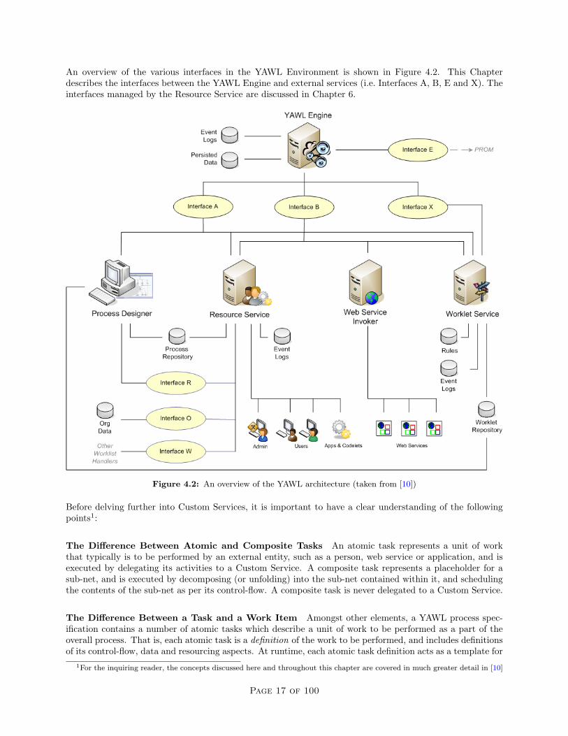
An overview of the various interfaces in the YAWL Environment is shown in Figure 4.2. This Chapterdescribes the interfaces between the YAWL Engine and external services (i.e. Interfaces A, B, E and X). Theinterfaces managed by the Resource Service are discussed in Chapter 6.
Figure 4.2: An overview of the YAWL architecture (taken from [10])
Before delving further into Custom Services, it is important to have a clear understanding of the followingpoints1:
The Difference Between Atomic and Composite Tasks An atomic task represents a unit of workthat typically is to be performed by an external entity, such as a person, web service or application, and isexecuted by delegating its activities to a Custom Service. A composite task represents a placeholder for asub-net, and is executed by decomposing (or unfolding) into the sub-net contained within it, and schedulingthe contents of the sub-net as per its control-flow. A composite task is never delegated to a Custom Service.
The Difference Between a Task and a Work Item Amongst other elements, a YAWL process spec-ification contains a number of atomic tasks which describe a unit of work to be performed as a part of theoverall process. That is, each atomic task is a definition of the work to be performed, and includes definitionsof its control-flow, data and resourcing aspects. At runtime, each atomic task definition acts as a template for
1For the inquiring reader, the concepts discussed here and throughout this chapter are covered in much greater detail in [10]
Page 17 of 100

one or more work items. That is, a work item is a runtime instance derived from an atomic task definition.An analogy might be: an atomic task is to a work item as a blueprint is to a house constructed from thatblueprint. The lifetime of a task is equal to the lifetime of its containing process specification. The lifetimeof a work item always falls within its containing process instance.
Task Decompositions A task decomposition is essentially a ‘contract’ between an atomic task and theexternal environment. That is, each atomic task that is required to interact with an external entity (externalto the Engine, such as a person, application or service) must reference a decomposition. Amongst otherthings, a decomposition is responsible for the definition of task-level input and output variables, and forspecifying which Custom Service will be responsible for the task’s execution at runtime. Several atomic tasksin a process may reference the same decomposition. A task without a decomposition is a so-called emptytask and is handled entirely within the Engine itself.
Work Item Creation When the Engine determines that an atomic task is ready to be scheduled, itcreates a work item derived from the task definition, sets the work item’s status to ‘Enabled’, and announcesthe work item’s enablement to the Custom Service specified in the task’s decomposition. Along with theannouncement, an XML representation of the work item is passed to the Custom Service. An enabled workitem does not contain instantiated data values for its input variables, since data mappings only take placeimmediately before the work item begins execution.
Work Item Check-out When a Custom Service indicates to the Engine that it is ready to check-out awork item, the Engine takes the enabled work item and creates a clone of it. The status of the original workitem is changed to ‘IsParent’, while the cloned work item (known as a child work item) is given the status‘Executing’ and has its data values instantiated (the reasons for this mechanism will become clearer in thediscussion of multiple-instance tasks later in this chapter). An XML representation of the child work item,including instantiated data values for its input variables, is returned to the Custom Service as the result ofa successful check-out.
Work Item Identifiers Each work item created by the Engine is given a unique identifier, which consistsof two parts, a case index and a task identifier, separated by a colon (:). The task identifier also consistsof two parts, the task’s name and a numeric string suffix assigned by the engine to ensure task identifieruniqueness, separated by an underscore ( ). Thus, an example work item id for a task named ‘Enrol’ mightbe 123:Enrol 5. The case index value of an enabled work item equates to the case identifier of its containingnet (thus ‘123’ in the example also refers to the case id of the root (or only) net of the process). When atask is set to ‘Executing’ status, a unique digit is added to its case index, using a dotted notation. So, forexample, a parent work item with an identifier of 123:Enrol 5 may have a executing child with identifier123.1:Enrol 5, to denote the first child work item created. Consequently, the work item passed to a CustomService with a notification of enablement, and the work item returned to a Custom Service as the result of asuccessful check-out, refer to two different work items.
A Note on Resourcing While the Engine is responsible for the control-flow and data perspectives of aprocess instance, it has no involvement in the resource perspective. That is, the Engine has no concept ofhow a work item is to be resourced, but delegates responsibility for that to a Custom Service (for example,the YAWL Resource Service). Therefore, concepts such as offering and allocation of work items do not existwithin the Engine. Rather, the Engine merely schedules (enables) work items, and delegates their executionto Custom Services. How a Custom Service handles the delegation is entirely up to the Custom Serviceinvolved; for example, the Resource Service adds the necessary “semantic layers” on top of an enabled workitem to denote it as ‘offered’ or ‘allocated’, but other Custom Services have no need for or knowledge of theseadded semantics.
With those points covered, the next section describes the creation of a simple Custom Service.
Page 18 of 100

4.2 A Simple Custom Service
This section describes the steps to follow to create a basic Custom Service. The YAWL Twitter Service willbe used as a running example. The Twitter Service, which may be used to send a status update to Twitter,is an example of a very simple Custom Service; the entire service consists of a single class and about 150lines of Java code.
At the core of each Custom Service are the following Interface B classes:
• org.yawlfoundation.yawl.engine.interfce.interfaceB.InterfaceB EnvironmentBasedServerThis class is a Java servlet and is responsible for receiving event notifications from the Engine.
• org.yawlfoundation.yawl.engine.interfce.interfaceB.InterfaceB EnvironmentBasedClientThis class provides methods that allow a Custom Service to call specific endpoints on the engine side.
• org.yawlfoundation.yawl.engine.interfce.interfaceB.InterfaceBWebsideControllerAn abstract utility class that encapsulates much of the functionality of the other two classes, and isdesigned to be extended by the primary class of each Custom Service.
These classes (and their dependent classes, as explained later) may be sourced from the YAWL engine distri-bution (.war file), or any existing Custom Service distribution, or the yawl-lib jar, or the YAWL Standalonejar file.
4.2.1 Creating the Service’s Primary Class
The first step is to create a new class that extends from InterfaceBWebSideController – this will be themain class (and in the case of the Twitter Service, the only class) of the new Custom Service. Besides a numberof helper methods and data members that the Custom Service inherits, InterfaceBWebSideControllercontains two abstract methods that all Custom Services must implement:
• public void handleEnabledWorkItemEvent(WorkItemRecord workItemRecord) This method is the end-point of an Engine enabled work item event notification; that is, it is called when the Engine createsa new work item and places it in the enabled state, and the Custom Service containing the method isthe one associated at design time with the work item.
• public void handleCancelledWorkItemEvent(WorkItemRecord workItemRecord) This method is invokedwhen an enabled or executing work item is cancelled by the engine (e.g. due to a cancellation occurringwithin the process control-flow). In principle, after this method has been invoked, a Custom Serviceshould not attempt to check-out or check-in the work item, and if the work item is in progress, itsprocessing should be stopped2.
Note that only the Custom Service associated with a particular work item will receive notifications via thesetwo methods.
Notice that both methods pass a WorkItemRecord object to the Custom Service. As noted earlier, theEngine side of the API passes an XML String representation of a work item together with these eventnotifications; InterfaceBWebSideController unmarshals the XML String, using its values to construct anorg.yawlfoundation.yawl.engine.interfce.WorkItemRecord object. WorkItemRecord is a convenienceclass designed to make it easier to interrogate the work item descriptors received without having to parse theXML itself. Table 4.1 contains the descriptors of a WorkItemRecord object; each has corresponding get andset methods, and each is stored as a String value, except for ‘datalist’, which is a JDOM Element. Thesemembers will be discussed as they arise later in this chapter.
2Note that YAWL does not support any notion of “atomic execution”, so no “rollback” is required when a work item iscancelled.
Page 19 of 100
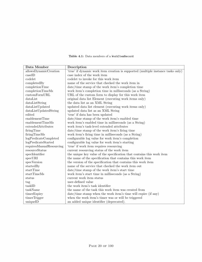
Table 4.1: Data members of a WorkItemRecord
Data Member DescriptionallowsDynamicCreation ‘true’ if dynamic work item creation is supported (multiple instance tasks only)caseID case index of the work itemcodelet codelet to invoke for this work itemcompletedBy name of the service that checked the work item incompletionTime date/time stamp of the work item’s completion timecompletionTimeMs work item’s completion time in milliseconds (as a String)customFormURL URL of the custom form to display for this work itemdataList original data list Element (executing work items only)dataListString the data list as an XML StringdataListUpdated updated data list element (executing work items only)dataListUpdatedString updated data list as an XML Stringedited ‘true’ if data has been updatedenablementTime date/time stamp of the work item’s enabled timeenablementTimeMs work item’s enabled time in milliseconds (as a String)extendedAttributes work item’s task-level extended attributesfiringTime date/time stamp of the work item’s firing timefiringTimeMs work item’s firing time in milliseconds (as a String)logPredicateCompleted configurable log value for work item’s completionlogPredicateStarted configurable log value for work item’s startingrequiresManualResourcing ‘true’ if work item requires resourcingresourceStatus current resourcing status of the work itemspecIdentifier the unique key value of the specification that contains this work itemspecURI the name of the specification that contains this work itemspecVersion the version of the specification that contains this work itemstartedBy name of the service that checked the work item outstartTime date/time stamp of the work item’s start timestartTimeMs work item’s start time in milliseconds (as a String)status current work item statustag user-defined valuetaskID the work item’s task identifiertaskName the name of the task this work item was created fromtimerExpiry date/time stamp when the work item’s time will expire (if any)timerTrigger when the work item’s timer was or will be triggereduniqueID an added unique identifier (deprecated).
Page 20 of 100

4.2.2 Implementing the handleEnabledWorkItemEvent method
A Custom Service is responsible for ensuring that each work item delegated to it is checked out of theengine, and later returned to the Engine, together with its updated data as required, when it is deemedcomplete. The actions that a Custom Service performs between check-out and check-in are entirely in thehands of its developer. For simpler services, the basic technique is to encapsulate this behaviour within theimplementation of the handleEnabledWorkItemEvent method, so that it checks out the enabled work item,performs the desired action, and then checks the work item back into the engine.
Before a Custom Service can successfully check out a work item (or perform any other action via theAPI), it must first establish a valid session with the Engine. There are two API methods inherited fromInterfaceBWebSideController that serve this purpose:
• public String connect(String userID, String password)Attempts to create a session with the engine by passing authentication credentials and returning aunique session handle.
• public boolean checkConnection(String sessionHandle)Returns true if the session handle is currently valid.
The credentials passed to the connect method must match those entered for the Custom Service when it isregistered with the Engine (see Section 4.3.4 for details). If successful, a session handle (String) is returnedthat should be stored by the service for subsequent use whenever an API method is called. The session willbe maintained by the Engine for 60 minutes of inactivity (by default, or as configured); that is, a session willexpire if it is not used in an API call within 60 consecutive minutes (each API call restarts the timer). ThecheckConnection method should therefore be called immediately before each API method call to ensure thesession is still active.
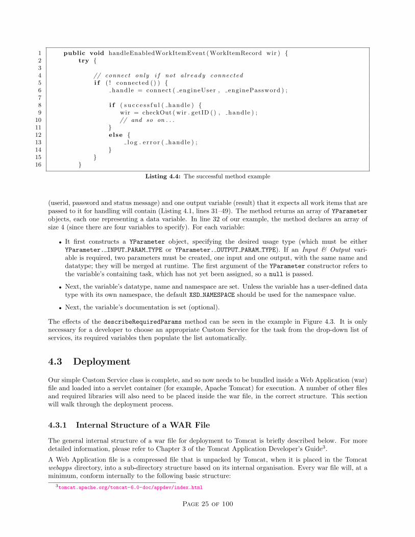
As an illustration of what’s been discussed so far, Listing 4.1 shows the Twitter Service’s entire public-facingcode, including the two abstract method implementations. Note the following:
• The TwitterService class extends InterfaceBWebsideController (line 1).
• A global String variable to store a session handle is declared (line 4).
• Final userid and password variables are declared (lines 6 & 7). These credentials must match thoseregistered for the service within the Engine. Note that InterfaceBWebsideController encrypts thepassword before it is sent across the API.
• The two abstract ‘event’ methods mentioned above are implemented (lines 9–25, and line 27). Notethat in this example the cancelled work item event is implemented as an empty method for simplicity(In the unlikely event that a cancel event is received while the handle Enabled event is still active, itwill be handled by catching the exception that will be thrown later by the checkinWorkItem method).More complex Custom Services would implement this method to stop processing of the work item andtake any required compensatory actions.
• The first thing the handleEnabledWorkItemEvent method does is to ensure it has a valid connectionto the Engine. It does that by first calling its own connected method, and if that returns false, callsthe connect method with the userid and password declared above, which if successful will assign a validsession handle value to the handle variable. Again for simplicity, the handle is not checked again afterthe call to connect, since an invalid session handle will be caught by the checkOut method throwingan exception.
• The connected method calls the checkConnection method only if the session handle is not currentlynull (lines 51–53).
• Again for simplicity, the catch block (lines 21–23) handles any Exception generically; it is recommended,of course, that each of the exceptions that may the thrown in the try block is handled in a moreappropriate way.
Page 21 of 100

1 public class Twit t e rSe rv i c e extends Inte r faceBWebs ideContro l l e r {23 // ho l d s a s e s s i on handle to the engine4 private St r ing handle = null ;56 private f ina l St r ing eng ineUser = ” t w i t t e r S e r v i c e ” ;7 private f ina l St r ing enginePassword = ” yTwitter ” ;89 public void handleEnabledWorkItemEvent ( WorkItemRecord wir ) {
10 try {1112 // connect on ly i f not a l r eady connected13 i f ( ! connected ( ) ) handle = connect ( engineUser , enginePassword ) ;1415 // checkout . . . p roces s . . . check in16 wir = checkOut ( wir . getID ( ) , handle ) ;17 St r ing r e s u l t = updateStatus ( wir ) ;18 checkInWorkItem ( wir . getID ( ) , wir . getDataList ( ) ,19 getOutputData ( wir . getTaskName ( ) , r e s u l t ) , null , handle ) ;20 }21 catch ( Exception i o e ) {22 i o e . pr intStackTrace ( ) ;23 }24 }2526 // have to implement a b s t r a c t method , but have no need f o r t h i s event27 public void handleCancelledWorkItemEvent ( WorkItemRecord workItemRecord ) { }2829 // the s e parameters are au t oma t i c a l l y i n s e r t e d ( in the Edi tor ) in t o a t a s k30 // decomposi t ion when t h i s s e r v i c e i s s e l e c t e d from the l i s t31 public YParameter [ ] descr ibeRequiredParams ( ) {32 YParameter [ ] params = new YParameter [ 4 ] ;33 params [ 0 ] = new YParameter ( null , YParameter . INPUT PARAM TYPE) ;34 params [ 0 ] . setDataTypeAndName ( ” s t r i n g ” , ” s t a t u s ” , XSD NAMESPACE) ;35 params [ 0 ] . setDocumentation ( ”The s t a t u s message to post to Twitter ” ) ;3637 params [ 1 ] = new YParameter ( null , YParameter . INPUT PARAM TYPE) ;38 params [ 1 ] . setDataTypeAndName ( ” s t r i n g ” , ” u s e r i d ” , XSD NAMESPACE) ;39 params [ 1 ] . setDocumentation ( ”Your Twitter ID” ) ;4041 params [ 2 ] = new YParameter ( null , YParameter . INPUT PARAM TYPE) ;42 params [ 2 ] . setDataTypeAndName ( ” s t r i n g ” , ”password” , XSD NAMESPACE) ;43 params [ 2 ] . setDocumentation ( ”Your Twitter password” ) ;4445 params [ 3 ] = new YParameter ( null , YParameter . OUTPUT PARAM TYPE) ;46 params [ 3 ] . setDataTypeAndName ( ” s t r i n g ” , ” r e s u l t ” , XSD NAMESPACE) ;47 params [ 3 ] . setDocumentation ( ”The s t a t u s r e s u l t or e r r o r message returned ” ) ;48 return params ;49 }5051 private boolean connected ( ) throws IOException {52 return handle != null && checkConnection ( handle ) ;53 }
Listing 4.1: The Twitter Service’s public methods
Page 22 of 100
After the connection has been established and/or checked, the method checkOut is invoked to check out theenabled work item. This method requires two parameters: the enabled work item’s ID, which is retrievedby using the WorkItemRecord.getID() method, and a valid session handle (see Listing 4.1, line 16). Ifsuccessful, the checkOut method returns a WorkItemRecord representing the executing, child work item.Remember, the WorkItemRecord returned by the checkout method represents a different work item instancefrom the one passed to the handleEnabledWorkItemEvent method:
• their identifiers are different.
• the checked-out work item has ’Executing’ status (instead of ’Enabled’).
• the checked-out work item has an instantiated datalist.
ASIDE: The TwitterService, like most simpler Custom Services, reuses the same WorkItemRecord object tostore the checked-out work item, effectively discarding the original, since it has no further need to referencethe initial, enabled work item. More complex Custom Services may need to keep the original work item aswell, in which case the distinction between them becomes very important.
Once the work item has been checked-out, the Custom Service can perform the appropriate actions for it. Inour example, an updateStatus method is called (line 17 of Listing 4.1), which takes the data contained inthe work item and uses it to connect to Twitter, pass it the specified status update and retrieve the resultingmessage (the actual machinations of how this is achieved is not of concern here).
When the appropriate action has been completed, the work item can be checked back into the Engine bycalling the checkInWorkItem method. The method has five parameters:
• String itemid : the identifier of the work item being checked in. Note that this must be the identifier ofthe checked-out work item, and not that of the work item passed to the handleEnabledWorkItemEventmethod.
• Element inputData: the set of input data variables and values as contained in the checked-out workitem. In almost all cases, a call to the WorkItemRecord’s getDataList method is used to fulfil thisparameter.
• Element outputData: the set of output data variables and values required (see below for more).
• String logPredicate: a piece of configured text to be logged in the Engine’s process logs along with otherlogged values representing this work item’s completion. A null argument is acceptable if there is nolog predicate.
• String handle: a valid session handle.
The outputData parameter requires a correctly formatted JDOM Element containing a complete list ofoutput data variables and values expected by the Engine for this work item. Our TwitterService exampleuses a getOutputData method to construct an appropriate Element; that method can be seen in Listing 4.2.
Note that the getOutputData method receives two parameters: the name of the task (retrieved by callingthe checked-out WorkItemRecord’s getTaskName method on line 19 of Listing 4.1) and the result returnedfrom the Twitter Service. The getOutputData method creates a containing Element with the same nameas the task (line 2); it is a mandatory requirement that the output data Element has the same name as thetask represented by the work item. Next, it creates another Element called “result” — this is the name ofonly output variable for work items handled by the Twitter Service — and assigns the value contained inthe variable data to it. Finally, it adds the “result” Element (representing the output variable and its value)as a child to the taskName Element (representing the container) and returns the constructed Element to bepassed back to the Engine via the checkInWorkItem method. An example of how the Element would appearas XML can be seen in Listing 4.3.
ASIDE: In our TwitterService example, we have assumed that each API method call is successful and thusreturns the expected result. In reality, if an API method does not succeed, it may throw an exception or
Page 23 of 100

1 private Element getOutputData ( S t r ing taskName , S t r ing data ) {2 Element output = new Element ( taskName ) ;3 Element r e s u l t = new Element ( ” r e s u l t ” ) ;4 r e s u l t . setText ( data ) ;5 output . addContent ( r e s u l t ) ;6 return output ;7 }
Listing 4.2: The Twitter Service’s getOutputData method
1 <myUpdateStatusTask>2 <r e s u l t>Update s u c c e s s f u l .</ r e s u l t>3 </myUpdateStatusTask>
Listing 4.3: Example contents of an Element produced by the Twitter Service’s getOutputData method
return a diagnostic message describing the problem encountered. Methods that return a String value (forexample, the connect and checkInWorkItem methods) should have their returned value checked insteadof simply assuming the call was successful. A convenience method called successful is inherited fromInterfaceBWebsideController by Custom Services that, when passed the result of an API call that returnsa String value, will return a boolean false if the result contains a diagnostic method rather than the expectedresult. An example on the use of the successful method can be see in in Listing 4.4. For API methodsthat return objects to Custom Services, an exception is thrown containing a diagnostic message if the call isunsuccessful. For example, the checkOut method throws a YAWLException if the check-out was unsuccessful.Additionally, each API method call will throw an IOException if the Engine can’t be reached.
4.2.3 Implementing the handleCancelledWorkItemEvent method
Sometimes, a work item that is being handled by a Custom Service is cancelled by the Engine before theservice has checked it out or before it has completed processing it. Cancellation may occur when a work item isa member of another task’s cancellation set, or when it is a member of a deferred choice construct, or when anadministrator cancels a case, or as a result of an exception handling routine. In any event, when a work item iscancelled the Engine notifies the appropriate Custom Service by calling its handleCancelledWorkItemEventmethod. The Custom Service can then take whatever action is appropriate by implementing the method(as one of two InterfaceBWebsideController’s abstract methods, it must be implemented by each CustomService).
For example, the Twitter Service takes no action at all, implementing the method with an empty body. Onthe other hand, the Worklet Service, which launches whole case instances for the work items it handles, needsto take appropriate action to cancel any cases it may have launched on behalf of the cancelled work item;the Resource Service must take action to remove the work item from any work queues it resides in, clean upits internal caches and so on.
4.2.4 Overriding the describeRequiredParams method
A well behaved Custom Service, which expects to receive particular data variables in order to perform theactions of a work item, will override the describeRequiredParams method. The purpose of this method isto allow Custom Services to specify exactly what input and output variables it requires. At design time,when a designer chooses the Custom Service to associate with a task in the Editor, the Editor will callthe describeRequiredParams method (using the Interface B API) and populate the task with the specifieddata variables, saving the designer the effort of manually creating the required variables and thereby greatlyreducing the margin for errors occurring at runtime.
Our TwitterService example overrides the describeRequiredParams method to specify 3 input variables
Page 24 of 100
1 public void handleEnabledWorkItemEvent ( WorkItemRecord wir ) {2 try {34 // connect on ly i f not a l r eady connected5 i f ( ! connected ( ) ) {6 handle = connect ( engineUser , enginePassword ) ;78 i f ( s u c c e s s f u l ( handle ) {9 wir = checkOut ( wir . getID ( ) , handle ) ;
10 // and so on . . .11 }12 else {13 l o g . e r r o r ( handle ) ;14 }15 }16 }
Listing 4.4: The successful method example
(userid, password and status message) and one output variable (result) that it expects all work items that arepassed to it for handling will contain (Listing 4.1, lines 31–49). The method returns an array of YParameterobjects, each one representing a data variable. In line 32 of our example, the method declares an array ofsize 4 (since there are four variables to specify). For each variable:
• It first constructs a YParameter object, specifying the desired usage type (which must be eitherYParameter. INPUT PARAM TYPE or YParameter. OUTPUT PARAM TYPE). If an Input & Output vari-able is required, two parameters must be created, one input and one output, with the same name anddatatype; they will be merged at runtime. The first argument of the YParameter constructor refers tothe variable’s containing task, which has not yet been assigned, so a null is passed.
• Next, the variable’s datatype, name and namespace are set. Unless the variable has a user-defined datatype with its own namespace, the default XSD NAMESPACE should be used for the namespace value.
• Next, the variable’s documentation is set (optional).
The effects of the describeRequiredParams method can be seen in the example in Figure 4.3. It is onlynecessary for a developer to choose an appropriate Custom Service for the task from the drop-down list ofservices, its required variables then populate the list automatically.
4.3 Deployment
Our simple Custom Service class is complete, and so now needs to be bundled inside a Web Application (war)file and loaded into a servlet container (for example, Apache Tomcat) for execution. A number of other filesand required libraries will also need to be placed inside the war file, in the correct structure. This sectionwill walk through the deployment process.
4.3.1 Internal Structure of a WAR File
The general internal structure of a war file for deployment to Tomcat is briefly described below. For moredetailed information, please refer to Chapter 3 of the Tomcat Application Developer’s Guide3.
A Web Application file is a compressed file that is unpacked by Tomcat, when it is placed in the Tomcatwebapps directory, into a sub-directory structure based on its internal organisation. Every war file will, at aminimum, conform internally to the following basic structure:
3tomcat.apache.org/tomcat-6.0-doc/appdev/index.html
Page 25 of 100

Figure 4.3: Required Variables Populated from the describeRequiredParams method
• a root directory, which typically contains any html and jsp files (and supporting files like JavaScriptand style sheet files) used by the service, although more complex services may have these files arrangedin sub-directories.
• a sub-directory of the root called WEB-INF, which contains:
– a web.xml file, more formally referred to as a Web Application Deployment Descriptor. This fileis an XML file containing configuration information for the application, and is discussed in moredetail below.
– a sub-directory called classes, where any required class files, that are not contained in jar libraries,are placed. The directory structure under the classes directory must match the package structureof any classes placed here. For example, any YAWL classes should be placed in a sub-directorystructure beginning with /org/yawlfoundation/yawl.
– a sub-directory called lib, where any jar libraries that the application requires are to be placed.
Page 26 of 100

4.3.2 Required Files
This section describes the absolute minimum set of files (classes and jars) required to be bundled with a basicCustom Service. Of course, particular Custom Services will require other files, depending on what the serviceactually does and how it is realised. These class files can be found in any of the installed YAWL CustomServices, or within the yawl-lib-xx.jar4 library (which, if placed in the classpath of a service, negates theneed to explicitly include these files in the service).
Firstly, these YAWL Interface B client side classes are mandatory inclusions for all Custom Services (packageorg.yawlfoundation.yawl.engine.interfce.interfaceB):
• IBControllerCache: caches recently accessed engine objects on the client side (specifications, taskinformation, work items, and so on).
• InterfaceB EnvironmentBasedClient: the service side API for service to engine calls.
• InterfaceB EnvironmentBasedServer: the service side receiver of event notifications from the engine,which are passed on to the Custom Service’s primary class.
• InterfaceBWebsideController: the base class of the Custom Service’s primary class.
The above classes require the inclusion of these dependent classes:
• Package org.yawlfoundation.yawl.elements:
– YAttributeMap: a map of attributes (key=value pairs).
– YSpecVersion: stores the version descriptors for a YAWL specification.
– YVerifiable: a Java interface implemented by several required classes; provides for self-verificationof a class’s data structures.
• Package org.yawlfoundation.yawl.elements.data:
– YParameter: stores variable types and descriptors.
– YVariable: a declared variable of a net or task.
• Package org.yawlfoundation.yawl.engine:
– YSpecification: the container for a YAWL specification.
– YSpecificationID: a unique identifier for each specification.
• Package org.yawlfoundation.yawl.engine.interfce:
– Interface Client: the base class of all YAWL API’s; provides basis for HTTP communicationbetween the Engine and Custom Services.
– Marshaller: converts XML Strings to their equivalent YAWL objects and vice versa.
– ServletUtils: some generic servlet utility methods.
– SpecificationData: stores specification definition data and descriptors.
– TaskInformation: stores task definition descriptors, including task parameters.
– WorkItemRecord: stores information describing a work item.
– YParametersSchema: stores descriptors of task-level parameter sets.
• Package org.yawlfoundation.yawl.engine.logging:
– YLogDataItem: definition of a item to be added to the logging of a process event.
– YLogDataItemList: a list of the above items.4where xx refers to the current YAWL release version (e.g. yawl-lib-2.1.jar).
Page 27 of 100
• Package org.yawlfoundation.yawl.util:
– CharSetFilter: ensures all strings passed via HTTP communications between the Engine andservices use UTF-8 encoding.
– JDOMUtil: various utility methods for converting Strings to JDOM objects and vice versa.
– PasswordEncryptor: hashes passwords on the service side for passing to the engine.
– StringUtil: various String manipulation methods.
In addition, the above classes require these external jar libraries to be available to the Custom Service, eitherin the Service’s /WEB-INF/lib directory, or elsewhere on the classpath:
• jdom.jar
• log4j.jar
• commons-codec-1.4.jar
Of course, war files representing any but the most basic of Custom Services can (and often do) include otherdirectories, class and jar files, and other contents besides those stated. A good idea is to browse the structuresof the various YAWL services to gain some insight into how things are typically arranged.
4.3.3 The Deployment Descriptor File (web.xml)
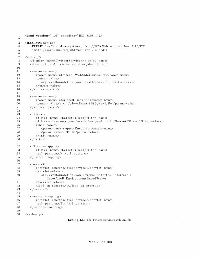
Every Custom Service must include a web.xml file in its WEB-INF directory. The file contains the necessarydeployment configuration values for the service. As an example, the Twitter Service’s web.xml is shown inListing 4.5. This example may be copied for use by basic Custom Services - only a few values need to bechanged in most cases, as described below.
In the basic web.xml file example:
• The name the Custom Service (line 8) and a brief description (line 9) are provided. These values areused only by the Tomcat Manager tool (YAWL doesn’t refer to them). The values should be set tomatch those of your Custom Service.
• A context parameter named InterfaceBWebsideController is defined (lines 11–16). The value of thisparameter must match the fully qualified name of your service’s primary class (which extends fromInterfaceBWebsideController class. At startup, an instance of the primary class referred to iscreated.
• A second context parameter named InterfaceB Backend is defined (lines 18–21). The value of thisparameter must match the URL of the Engine’s Interface B API. For a locally installed Engine, thisparameter value can be left unchanged; if the Engine is installed remotely, the URL’s host name shouldbe changed to that of the remote Engine. The standard tomcat port (:8080) should be changed only ifthe Engine’s Tomcat container has modified its port from the default. In all cases, the URL must endin /yawl/ib – the path of the Engine’s Interface B endpoint.
• A servlet character set filter is provided (lines 23–35), which should be included as-is in all CustomService web.xml files. The filter ensures that all Strings passed between the Engine and Services willbe encoded with the UTF-8 character set.
• The definition of the servlet for the Custom Service is at lines 37–43. The servlet-class value shouldnot be changed - it defines the fully qualified name of the class that receives notifications from the Engine(and is inherited in your service’s primary class, as it extends from InterfaceBWebsideController).The servlet-name value may be changed to match that of your service.
Page 28 of 100
1 <?xml version=” 1 .0 ” encoding=”ISO−8859−1”?>23 < !DOCTYPE web−app4 PUBLIC ”−//Sun Microsystems , Inc . //DTD Web Appl i ca t ion 2 .3//EN”5 ” h t t p : // java . sun . com/dtd/web−app 2 3 . dtd”>67 <web−app>8 <di sp lay−name>Twit t e rSe rv i c e</ d i sp lay−name>9 <d e s c r i p t i o n>A t w i t t e r s e r v i c e</ d e s c r i p t i o n>
1011 <context−param>12 <param−name>Inter faceBWebSideContro l l e r</param−name>13 <param−value>14 org . yawl foundat ion . yawl . t w i t t e r S e r v i c e . Twi t t e rSe rv i c e15 </param−value>16 </ context−param>1718 <context−param>19 <param−name>InterfaceB BackEnd</param−name>20 <param−value>h t t p : // l o c a l h o s t : 8 0 8 0 /yawl/ ib</param−value>21 </ context−param>2223 < f i l t e r>24 < f i l t e r −name>C h a r s e t F i l t e r</ f i l t e r −name>25 < f i l t e r −c l a s s>org . yawl foundat ion . yawl . u t i l . C h a r s e t F i l t e r</ f i l t e r −c l a s s>26 < i n i t−param>27 <param−name>requestEncoding</param−name>28 <param−value>UTF−8</param−value>29 </ i n i t−param>30 </ f i l t e r>3132 < f i l t e r −mapping>33 < f i l t e r −name>C h a r s e t F i l t e r</ f i l t e r −name>34 <ur l−pattern>/∗</ ur l−pattern>35 </ f i l t e r −mapping>3637 <s e r v l e t>38 <s e r v l e t−name>t w i t t e r S e r v i c e</ s e r v l e t−name>39 <s e r v l e t−c l a s s>40 org . yawl foundat ion . yawl . eng ine . i n t e r f c e . i n t e r f a c e B .
Inter faceB EnvironmentBasedServer41 </ s e r v l e t−c l a s s>42 <load−on−s ta r tup>1</ load−on−s ta r tup>43 </ s e r v l e t>4445 <s e r v l e t−mapping>46 <s e r v l e t−name>t w i t t e r S e r v i c e</ s e r v l e t−name>47 <ur l−pattern>/ ib</ ur l−pattern>48 </ s e r v l e t−mapping>4950 </web−app>
Listing 4.5: The Twitter Service’s web.xml file
Page 29 of 100

• The definition of the servlet mapping for the Custom Service is at lines 45–48. The servlet-name valuehere and the servlet-name value provided in the servlet definition (in the previous point) must match.The url-pattern value must match the path part of the URI provided to the Engine when the CustomService was registered; by convention, Custom Services use the path /ib. For example, the TwitterService is registered with the Engine with the URI http://localhost:8080/twitterService/ib.The twitterService part matches the name of the war file deployed. The /ib part matches theurl-pattern value provided here. The result is that when the Engine sends a notification the the URIit has registered for your service, that URI is mapped by Tomcat to the Servlet class defined in theprevious point, allowing your Custom Service to receive those notification events.
The Twitter Service example is a minimal web.xml that suits the requirements of most Custom Services, buta web.xml can contain any number of context parameters, servlet definitions, filters and so on. For a morecomplex example, see the Resource Service’s web.xml file.
4.3.4 Registering the Service with the Engine
The Engine requires each Custom Service wishing to communicate with it to first be registered. Registrationis achieved via the Services web form (Figure 4.4), which is available to all users with administrative access.A service can be added by providing a name, a password and confirmation, a URI and a Description. Thepassword and confirmation password must match each other, and name and password must also exactlymatch the credentials that will be used by the service to log onto the Engine. For example, the credentialsfor the Twitter Service are declared in the service’s code (Listing 4.1, lines 6–7); they are used by the Servicewhen it connects to the Engine.
The URI entered is validated by contacting it and waiting for an appropriate response, so care should betaken that (1) the Service’s war file is already deployed in Tomcat, and (2) the URI provided exactly matchesthat specified by the service (i.e. the first part of the path matches the name of the Service’s war file, andthe last part matches the servlet-mapping parameter value for the InterfaceB EnvironmentBasedServerservlet class as defined in the Service’s web.xml – by convention the last part of the path is /ib).
When the Add button is clicked, if the credentials and URI entered are correct, the service will be successfullyregistered with the Engine. If not, an explanatory error message will be displayed.
4.4 Additional Topics
We’ve now covered all the fundamentals of creating and deploying a basic YAWL Custom Service. In thissection, we will examine some additional topics that extend the capabilities of Custom Services.
4.4.1 Handling Multiple-Instance Atomic Tasks
In the YAWL language, there are two kinds of atomic tasks: ordinary single-instance tasks, each of which cre-ates one executable (child) work item, and multiple-instance tasks, each of which creates multiple executable(child) work items.
As described in Section 4.1, when a single-instance atomic task is checked out by a Custom Service, a childwork item is created by the Engine, given the status ‘Executing’, and returned to the service. When amultiple-instance atomic task is checked out by a Custom Service, the mechanism is similar, but a little moreinvolved:
• A (specified at design time) number of child work items are created by the Engine;
• One of the children, chosen indiscriminately, is given a status of ‘Executing’ and returned to service;and
• The remainder of the child work items are given a status of ‘Fired’ and remain in the Engine.
Page 30 of 100
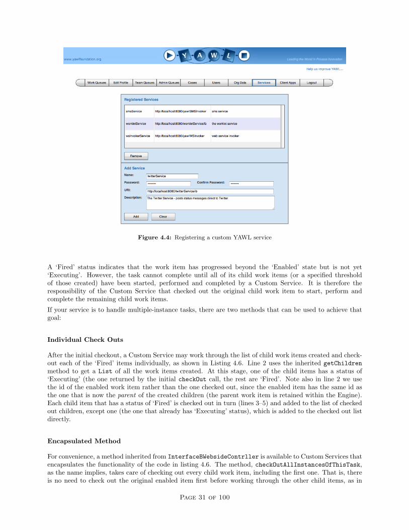
Figure 4.4: Registering a custom YAWL service
A ‘Fired’ status indicates that the work item has progressed beyond the ‘Enabled’ state but is not yet‘Executing’. However, the task cannot complete until all of its child work items (or a specified thresholdof those created) have been started, performed and completed by a Custom Service. It is therefore theresponsibility of the Custom Service that checked out the original child work item to start, perform andcomplete the remaining child work items.
If your service is to handle multiple-instance tasks, there are two methods that can be used to achieve thatgoal:
Individual Check Outs
After the initial checkout, a Custom Service may work through the list of child work items created and check-out each of the ‘Fired’ items individually, as shown in Listing 4.6. Line 2 uses the inherited getChildrenmethod to get a List of all the work items created. At this stage, one of the child items has a status of‘Executing’ (the one returned by the initial checkOut call, the rest are ‘Fired’. Note also in line 2 we usethe id of the enabled work item rather than the one checked out, since the enabled item has the same id asthe one that is now the parent of the created children (the parent work item is retained within the Engine).Each child item that has a status of ‘Fired’ is checked out in turn (lines 3–5) and added to the list of checkedout children, except one (the one that already has ‘Executing’ status), which is added to the checked out listdirectly.
Encapsulated Method
For convenience, a method inherited from InterfaceBWebsideContrller is available to Custom Services thatencapsulates the functionality of the code in listing 4.6. The method, checkOutAllInstancesOfThisTask,as the name implies, takes care of checking out every child work item, including the first one. That is, thereis no need to check out the original enabled item first before working through the other child items, as in
Page 31 of 100

1 List<WorkItemRecord> checkedOut = new ArrayList<WorkItemRecord >() ;2 for ( WorkItemRecord c h i l d : getChi ldren ( enabledItem . getID ( ) , s e s s i onHand l e ) ) {3 i f ( c h i l d . ge tStatus ( ) . equa l s ( WorkItemRecord . s t a tu sF i r ed ) ) {4 checkedOut . add ( checkOut ( c h i l d . getID ( ) , s e s s i onHand l e ) ) ;5 }6 else checkedOut . add ( c h i l d ) ;7 }
Listing 4.6: Checking out the work items of a multiple-instance task individually
1 public void handleEnabledWorkItemEvent ( WorkItemRecord wir ) {2 try {34 // connect on ly i f not a l r eady connected5 i f ( ! connected ( ) ) handle = connect ( engineUser , enginePassword ) ;67 // checkout . . . p roces s . . . check in8 List<WorkItemRecord> checkedOut =9 checkOutAllInstancesOfThisTask ( wir , handle ) ;
10 for ( WorkItemRecord c h i l d : checkedOut ) {11 St r ing r e s u l t = updateStatus ( c h i l d ) ;12 checkInWorkItem ( c h i l d . getID ( ) , c h i l d . getDataList ( ) ,13 getOutputData ( c h i l d . getTaskName ( ) , r e s u l t ) , null , handle ) ;14 }15 }16 catch ( Exception i o e ) {17 i o e . pr intStackTrace ( ) ;18 }19 }
Listing 4.7: Checking out all the work items of a task in a single call
the previous method. Indeed, the checkOutAllInstancesOfThisTask method is passed the entire enabledWorkItemRecord as an argument, and it will throw an Exception if its status is anything other than ‘Enabled’.The method can be used for single-instance atomic tasks, too. The usage of the method is demonstrated inListing 4.7, which shows an alternate handleEnabledWorkItemEvent implementation to the one in Listing4.1.
Each work item created for a multiple-instance task may contain different data values, so each is used in aupdateStatus call (line 10), and each is checked in individually.
A multiple instance task is not considered complete until all (or a specified threshold) of its child workitems have been checked in to the Engine, which keeps track of the children checked out and back in via theinternally-held parent work item from which the child items were created. Therefore, a Custom Service doesnot need to concern itself with the number of child work items checked out or checked in for a task, only thatit eventually checks in each item that it checks out.
4.4.2 Other Interface B Events
While the two mandatory events discussed earlier must be implemented by all Custom Services, there are anumber of other events generated by the Engine that a Custom Service may choose to optionally implement.They are:
Page 32 of 100

handleEngineInitialisationCompletedEvent()
The Engine sends this event to all registered Custom Services immediately after it is started and completes allof its initialisation tasks. The notification of this event is useful to Custom Services because typically, sinceTomcat starts web applications in alphabetical order, a Custom Service will be started before the Engine(contained in yawl.war). Thus, a Custom Service may use this event to undertake any final initialisationtasks that depend on the availability of a running Engine.
handleTimerExpiryEvent(WorkItemRecord item)
Any atomic task may be associated with a timer. If the timer expires before its child work items havecompleted, the Engine will fire this event, allowing a Custom Service that has checked out the task toperform the appropriate action.
handleCompleteCaseEvent(String caseID, String caseData)
Notifies either one or all Custom Services when a process instance completes. The caseData argument isan XML String of the case’s output data. Some Custom Services need to be aware of case completions, forexample the Worklet Service, which launches cases as substitutes for checked out work items, and checks thework items back in when the launched case completes. Whether one or all Custom Services are notified ofa case completion is dependent on how the case is launched – see Launching a Case in the next section formore details.
handleCancelledCaseEvent(String caseID)
Notifies all Custom Services when a process instance is cancelled. Any Custom Service that monitors runningcases will use this event to take whatever action is appropriate for the service. For example, the ResourceService uses this event to remove any work items associated with the case from its work queues, and toremove the case from the list of running cases in the Case Management form.
handleWorkItemStatusChangeEvent(WorkItemRecord item, String oldStatus, String newSta-tus)
Notifies all Custom Services when the status of a work item changes. Services may choose to handle this eventto take any action appropriate – usually this means reacting to a status change caused by another CustomService (since the service would already know of any changes it instigated). Note that initial statuses are notannounced via this method (e.g. ‘Enabled’ or ‘Fired’), since they are the statuses a work item begins with,a status change is not represented by a work item creation. Note also that the work item passed via thismethod does not contain the item’s output data when a work item completes, because the output data is neverincorporated into the work item, rather it is submitted separately to the Engine (via the checkInWorkItemmethod).
For examples of implementations of each of these event handlers, review those of the ResourceManagerclass of the Resource Service.
4.4.3 Launching a Case
A case (process instance) can be launched by a Custom Service via Interface B. Listing 4.8 shows a typicalimplementation. On line 4, the launchCase method of the interfaceBClient object, inherited directlyfrom InterfaceBWebsideController, is called with the following arguments:
Page 33 of 100

1 public St r ing launchCase ( YSpec i f i ca t i on ID specID , St r ing caseData )2 throws IOException {3 YLogDataItemList logData = getLogData ( ) ;4 S t r ing caseID = i n t e r f a c e B C l i e n t . launchCase ( specID , caseData ,5 se s s ionHand le , logData ) ;6 i f ( ! s u c c e s s f u l ( caseID ) ) {7 // l e t the user know the r e ’ s a problem8 }9 return caseID ;
10 }
Listing 4.8: Launching a new case
1 St r ing caseID = i n t e r f a c e B C l i e n t . launchCase ( specID , caseData ,2 se s s ionHand le , logData , myServiceURI ) ;
Listing 4.9: Launching a new case with a case observer
• YSpecificationID specid: The ID of the specification from which to launch a case. There is anassumption that the specification has already been loaded into the Engine.
• String caseData: An XML String containing values for any net-level input variables. The root nameof the XML structure must match either the name of the root net or the URI (name) of the specification,while its contents must include the correct name and valid data value for each input variable expected.If the specification has no net-level input variables, a null may be passed for this argument.
• String sessionHandle: A valid and active session handle previously obtained from the Engine.
• YLogDataItemList logData: A list of log predicate Strings to insert into the Engine’s process logswhen the case starts, over and above the default case launch log events. If there are no log predicatesto be logged for the case launch, a null may be passed for this argument (in which case line 3 of Listing4.8 can be ignored).
The call to interfaceBClient.launchCase will return either the case ID of the newly launched case if thelaunch was successful, or a diagnostic error message if it was not. Line 6 of Listing 4.8 uses the inheritedsuccessful method to determine if the returned value represents a successful case launch – if it does not,the returned String can be used to construct an informative error message to the user.
There is a second form of the launchCase method, as shown in Listing 4.9, that takes one extra argument– the URI String of the Custom Service launching the case (in most cases) – known as the ‘case observer’.The difference between the two methods is the effect on case completion notifications:
• For a case launched via the first method (without a case observer), all registered services are notifiedof the completion of the case;
• For a case launched via the second method (with a case observer), the observer is the only servicenotified of the completion of the case.
Note that it is acceptable for the case observer URI to differ from the URI of the Custom Service launchingthe case, if it is desired that a different service handles the case completion event.
4.5 Other Engine Interfaces
Besides Interface B, there three other interfaces through which services and applications can interact withthe YAWL Engine. This section introduces those three interfaces.
Page 34 of 100

1 public St r ing u p l o a d S p e c i f i c a t i o n ( F i l e s p e c F i l e ) throws IOException {2 Inter faceA EnvironmentBasedCl ient c l i e n t =3 new Inter faceA EnvironmentBasedCl ient ( ” http :// l o c a l h o s t :8080/ yawl/ i a ” ) ;4 return c l i e n t . u p l o a d S p e c i f i c a t i o n ( specF i l e , s e s s i onHand l e ) ;5 }
Listing 4.10: Uploading a Specification
4.5.1 Interface A
The focus of Interface A is to provide support for two fundamental functions:
• The uploading and unloading of specifications; and
• Registering, modifying and removing Custom Service and Client Application accounts.
To use Interface A, a service must access the class InterfaceA EnvironmentBasedClient, found in theorg.yawlfoundation.yawl.engine.interfce.interfaceA package, together with the dependent files listedin Section 4.3.2, either within its own war file, or via its classpath. Since the Engine does not generate anyevent notification on Interface A, no other inclusions are necessary.
Uploading and Unloading Specifications
Uploading a specification is quite straightforward, as shown in Listing 4.10. First, an interface client iscreated, by passing to its constructor the URI of the Engine’s Interface A endpoint (/yawl/ia) on lines 2–3,then calling the client’s uploadSpecification method with a File object that references a specification file(line 4). The String returned from the method will contain an diagnostic error message if there was an erroruploading the specification. These diagnostic messages can be quite informative, since the Engine verifies thesyntax of the specification and reports any errors or warnings found.
A second version of the uploadSpecification method accepts the specification as an XML String, insteadof a File object.
To unload a specification from the Engine, call the unloadSpecification method, passing the specificationidentifier and a valid session handle. Interface A also has connect and checkConnection methods, likeInterface B, for establishing and checking sessions with the Engine.
Service and Application Account Maintenance
Each Custom Service and Client Application must have its credentials registered with the Engine before theycan connect to it through one of its interfaces. Interface A provides the necessary methods to enable serviceand application registration and maintenance.
What makes a service a YAWL Custom Service is its ability to have the execution of a work item delegated toit. That is, every YAWL Custom Service implements Interface B and so is able to receive event notificationsof work item enablements, and so is able to be associated with tasks at design time (in the Editor). Anyweb service that does not implement Interface B, and all standalone applications and tools, do not meet thiscriterion, but nevertheless may connect with the Engine as a Client Application, rather than as a CustomService. For example, while the Monitor Service is a web service, deployed via a war file in Tomcat in thesame way as Custom Services, it does not implement Interface B and so is regarded as a Client Application.The Editor is an example of a standalone Client Application that communicates with the Engine.
ASIDE: YAWL has always supported a generic administrative logon called ‘admin’, which can be used byindividuals to logon to the default worklist, and by services and applications to connect to the YAWL Engine.Since the use of the generic logon is quite insecure, from version 2.1 onwards its use is discouraged, in favourof the unique logon credentials for each service and application as discussed in this section. While enabled
Page 35 of 100

1 public St r ing addReg i s t e r edServ i c e ( S t r ing name , S t r ing pw,2 St r ing ur i , S t r ing doco ) throws IOException {3 Inter faceA EnvironmentBasedCl ient c l i e n t =4 new Inter faceA EnvironmentBasedCl ient ( ” http :// l o c a l h o s t :8080/ yawl/ i a ” ) ;5 YAWLServiceReference s e r v i c e =6 new YAWLServiceReference ( ur i , null , name , pw, doco ) ;7 return c l i e n t . addYAWLService ( s e r v i c e , s e s s i onHand l e ) ;8 }
Listing 4.11: Registering a Custom Service with the Engine
by default, which allows for connections from unregistered services using the generic ‘admin’ user to succeed,the user may be disabled via a context-param in the Engine’s web.xml file. Once some administrative levelparticipants are added to YAWL via the default worklist, and once it is determined that there are no CustomServices relying on the generic logon, you are encouraged to disable it. All of the services and applicationsdeployed with a YAWL release use their own unique credentials.
Custom Service Registration and Maintenance
To use Interface A to register a Custom Service, the following additional classes are first required:
• org.yawlfoundation.yawl.elements.YAWLServiceReference: stores a reference to a Custom Ser-vice.
• org.yawlfoundation.yawl.authentication.YClient: the base class of the YAWLServiceReferenceand the YExternalClient classes.
An example of how a Custom Service may be registered with the Engine can be seen in Listing 4.11. First,an Interface A client is created (lines 3–4), then on lines 5–6 a new service reference object is constructed.The YAWLServiceReference constructor receives five arguments:
• uri: The absolute URI of the Custom Service.
• gateway: This argument is only relevant on the Engine side. All client side services should use a nullfor this argument.
• name: The logon name for the service.
• pw: The logon password for the service. The password is supplied in plain text – it will be encryptedvia the interface call.
• doco: A description of the Custom Service. This is the description that appears in the drop down listof services in the Editor.
The addYAWLService method is called on line 7, returning a diagnostic String describing the success orotherwise of the add attempt.
To remove a registered Custom Service, use the removeYAWLService(serviceURI, sessionHandle) method.
Client Application Registration and Maintenance
Client Application accounts are added, maintained and removed in a similar way to Custom Services. Listing4.12 shows the basic methods.
When adding or updating, the password argument should be passed as plain text, as it will be encrypted bythe Interface A client. When using the updateClientAccount method, the name argument must match that
Page 36 of 100

1 Inter faceA EnvironmentBasedCl ient c l i e n t =2 new Inter faceA EnvironmentBasedCl ient ( ” http :// l o c a l h o s t :8080/ yawl/ i a ” ) ;34 St r ing msg = c l i e n t . addClientAccount (name , password , doco , s e s s ionHand le ) ;56 msg = c l i e n t . updateClientAccount (name , password , doco , s e s s ionHand le ) ;78 msg = c l i e n t . removeClientAccount (name , se s s ionHand le ) ;
Listing 4.12: Interface A operations with Client Applications
1 YLogGatewayClient c l i e n t =2 new YLogGatewayClient ( ” http :// l o c a l h o s t :8080/ yawl/ logGateway” ) ;34 St r ing xesLog = c l i e n t . getSpec i f i cat ionXESLog ( specID , true , s e s s i onHand le ) ;
Listing 4.13: Interface E primary methods
of an existing client account (i.e. the name of a client account cannot be changed). Each method returns adiagnostic String describing the success or otherwise of the call.
The generic ‘admin’ logon is made available as a Client Application account, allowing administrators to changeits password via the updateClientAccount method. However, the ‘admin’ account cannot be removed via aremoveClientAccount call; an attempt to do so will result in an error message being returned. To removethe account, it needs to be set to disabled in the context parameter AllowGenericAdminID of the Engine’sweb.xml.
Please consult the YAWL javadoc for more details of the complete functionality set offered by Interface A.
4.5.2 Interface E
Interface E provides access to the Engine’s process logs. The are two output formats returned by the variousmethods of the interface, the majority are in plain XML, but case histories can also be retrieved in theOpenXES format, allowing the log output to be directly imported into the ProM process mining tool5.
To access Interface E, the YLogGatewayClient class needs to be added to your Custom Service (from the pack-age org.yawlfoundation.yawl.engine.interfce.interfaceE). An example of using Interface E is shownin Listing 4.13; note in particular that the Engine’s Interface E URI ends with the path /yawl/logGateway.The boolean argument in the getSpecificationXESLog method, when true, includes all variable data valuechanges in the output returned.
There are numerous methods to retrieve logged data for such things as:
• all the events of a particular case.
• all the events for a particular task instance.
• all the task instances of a particular case.
• all the task instances of a task definition.
• the data type for a particular data item (complex types included).
• all the events of all cases instantiated from a particular specification.
• all the cases started and/or cancelled by a particular Custom Service.
5www.processmining.org
Page 37 of 100
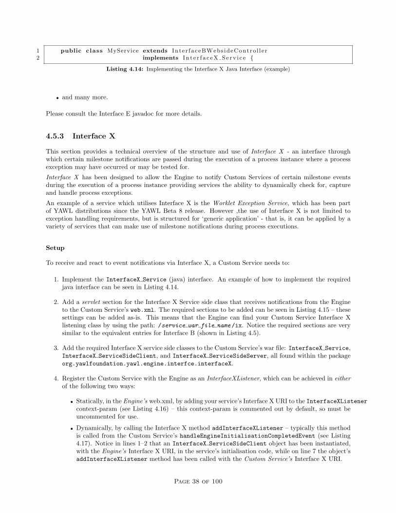
1 public class MyService extends Inte r faceBWebs ideContro l l e r2 implements I n t e r f a c e X S e r v i c e {
Listing 4.14: Implementing the Interface X Java Interface (example)
• and many more.
Please consult the Interface E javadoc for more details.
4.5.3 Interface X
This section provides a technical overview of the structure and use of Interface X - an interface throughwhich certain milestone notifications are passed during the execution of a process instance where a processexception may have occurred or may be tested for.
Interface X has been designed to allow the Engine to notify Custom Services of certain milestone eventsduring the execution of a process instance providing services the ability to dynamically check for, captureand handle process exceptions.
An example of a service which utilises Interface X is the Worklet Exception Service, which has been partof YAWL distributions since the YAWL Beta 8 release. However ,the use of Interface X is not limited toexception handling requirements, but is structured for ‘generic application’ - that is, it can be applied by avariety of services that can make use of milestone notifications during process executions.
Setup
To receive and react to event notifications via Interface X, a Custom Service needs to:
1. Implement the InterfaceX Service (java) interface. An example of how to implement the requiredjava interface can be seen in Listing 4.14.
2. Add a servlet section for the Interface X Service side class that receives notifications from the Engineto the Custom Service’s web.xml. The required sections to be added can be seen in Listing 4.15 – thesesettings can be added as-is. This means that the Engine can find your Custom Service Interface Xlistening class by using the path: /service war file name /ix. Notice the required sections are verysimilar to the equivalent entries for Interface B (shown in Listing 4.5).
3. Add the required Interface X service side classes to the Custom Service’s war file: InterfaceX Service,InterfaceX ServiceSideClient, and InterfaceX ServiceSideServer, all found within the packageorg.yawlfoundation.yawl.engine.interfce.interfaceX.
4. Register the Custom Service with the Engine as an InterfaceXListener, which can be achieved in eitherof the following two ways:
• Statically, in the Engine’s web.xml, by adding your service’s Interface X URI to the InterfaceXListenercontext-param (see Listing 4.16) – this context-param is commented out by default, so must beuncommented for use.
• Dynamically, by calling the Interface X method addInterfaceXListener – typically this methodis called from the Custom Service’s handleEngineInitialisationCompletedEvent (see Listing4.17). Notice in lines 1–2 that an InterfaceX ServiceSideClient object has been instantiated,with the Engine’s Interface X URI, in the service’s initialisation code, while on line 7 the object’saddInterfaceXListener method has been called with the Custom Service’s Interface X URI.
Page 38 of 100
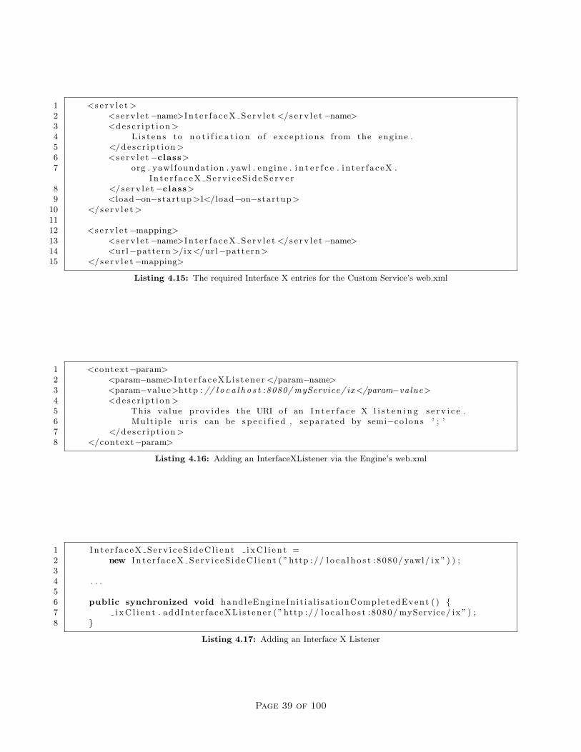
1 <s e r v l e t >2 <s e r v l e t−name>I n t e r f a c e X S e r v l e t </s e r v l e t−name>3 <d e s c r i p t i o n >4 L i s t e n s to n o t i f i c a t i o n o f except i on s from the eng ine .5 </d e s c r i p t i o n >6 <s e r v l e t−class>7 org . yawl foundat ion . yawl . eng ine . i n t e r f c e . i n t e r f a c eX .
I n t e r f a c e X S e r v i c e S i d e S e r v e r8 </s e r v l e t−class>9 <load−on−startup >1</load−on−startup>
10 </s e r v l e t >1112 <s e r v l e t−mapping>13 <s e r v l e t−name>I n t e r f a c e X S e r v l e t </s e r v l e t−name>14 <ur l−pattern >/ix </ur l−pattern>15 </s e r v l e t−mapping>
Listing 4.15: The required Interface X entries for the Custom Service’s web.xml
1 <context−param>2 <param−name>In t e r f a c eXL i s t ene r </param−name>3 <param−value>http : // l o c a l h o s t :8080/ myService/ ix </param−va lue>4 <d e s c r i p t i o n >5 This va lue prov ide s the URI o f an I n t e r f a c e X l i s t e n i n g s e r v i c e .6 Mult ip l e u r i s can be s p e c i f i e d , separated by semi−co l ons ’ ; ’7 </d e s c r i p t i o n >8 </context−param>
Listing 4.16: Adding an InterfaceXListener via the Engine’s web.xml
1 I n t e r f a c e X S e r v i c e S i d e C l i e n t i x C l i e n t =2 new I n t e r f a c e X S e r v i c e S i d e C l i e n t ( ” http :// l o c a l h o s t :8080/ yawl/ ix ” ) ) ;34 . . .56 public synchronized void hand leEng ine In i t i a l i s a t i onComple tedEvent ( ) {7 i x C l i e n t . addInte r f aceXLi s t ene r ( ” http :// l o c a l h o s t :8080/ myService / ix ” ) ;8 }
Listing 4.17: Adding an Interface X Listener
Page 39 of 100

The Interface X Package
The package org.yawlfoundation.yawl.engine.interfce.interfaceX contains the following entities:
• ExceptionGateway: a java interface that defines the event notifications that pass from the engine sideto the custom service side.
• InterfaceX Service: a java interface that defines the methods that must be implemented by thecustom service to receive event notifications.
• InterfaceX EngineSideClient: implements the ExceptionGateway interface. Receives the eventnotifications from the engine, translates them and their data sets to POST messages and passes themacross the interface.
• InterfaceX ServiceSideServer: a java Servlet that receives the POST messages passed across theinterface from the EngineSideClient, and translates them and their data sets into method calls to thecustom service (i.e. the methods implemented from the InterfaceX Service interface).
• InterfaceX ServiceSideClient: has a number of methods that are called from the custom service.Translates the method calls and their datasets into POST messages and passes them across the interface.
• InterfaceX EngineSideServer: a java Servlet that receives the POST messages passed across theinterface from the ServiceSideClient, and translates them and their data sets into method calls to theengine.
The logical layout of the interface can be seen schematically in Figure 4.5.
Figure 4.5: Schematic Overview
Of course, the items of interest to a Custom Service developer are those on the service side. These aredescribed in some detail below.
InterfaceX Service
By implementing this interface, a Custom Service must implement eight methods, seven of which are notifi-cation announcements from the engine side:
Page 40 of 100
• handleCheckCaseConstraintEvent(YSpecificationID specID, String caseID, String data,boolean preCheck)
This method is invoked by the Engine at two points in the lifecycle of a case, firstly when the case islaunched and again when it completes. It is designed to allow a Custom Service to check the case’sstarting and concluding case-level data to ensure they are valid, and to take appropriate action asrequired, but of course may be used for other purposes.
– specID is the identifier of the specification from which the case was instantiated;– caseID is the identifier of the case instance;– data is an XML String containing the current case-level variable values; and– preCheck denotes whether the case has just been launched (true), or it has just completed (false).
• handleCheckWorkItemConstraintEvent(WorkItemRecord wir, String data, boolean preCheck)
This method is invoked by the Engine at two points in the lifecycle of a work item, firstly whenthe workitem is enabled and again when it completes. It is designed to allow a Custom Service to checkthe workitem’s input and output data respectively to ensure it is valid, and to take appropriate actionas required before and after the workitem is executed, but of course may be used for other purposes.
– wir is the workitem record of the item in question;– data is a XML String of containing data values of the work item’s variables; and– preCheck denotes whether the work item has just been enabled (true), or it has just completed
(false).
• handleTimeoutEvent(WorkItemRecord wir, String taskList)
This method is invoked by the Engine when a work item timer reaches its expiry deadline.
– wir is the work item record that has expired; and– tasklist is a concatenated String of task identifiers of the form “[taskA, taskB, taskX]” repre-
senting a list of tasks which had work items running in parallel to the timed workitem when thetimeout occurred.
• handleCaseCancellationEvent(String caseID)
This method is invoked by the Engine when a case is cancelled.
– caseID is the identifier of the case instance.
• handleResourceUnavailableException(WorkItemRecord wir)
This method is invoked, not by the Engine, but by the Resource Service, whenever a work item isassigned to a resource and that resource is not currently available or does not exist.
– wir is the work item record that has an unavailable resource.
• handleWorkItemAbortException(WorkItemRecord wir)handleConstraintViolationException(WorkItemRecord wir)
These two methods are included in the interface for future implementation - that is, they are notyet implemented on the Engine side and so are never called. However, since they are included in theinterface, any Custom Service that implements it must include these definitions as empty methods.
• doGet(HttpServletRequest request, HttpServletResponse response)
Handles the servlet request that occurs when a browser client navigates to the custom service’s URI.Should be used to display a web page.
Page 41 of 100
InterfaceX ServiceSideClient
The Service-Side Client class provides a number of methods that may be called from the Custom Serviceto be invoked on the Engine side. The list below provides a brief overview of each. Most require an activesession with the engine.
String addInterfaceXListener(String listenerURI) throws IOException
Purpose: Registers the URI of the Custom Service with the engine. If successful, enables the custom serviceto receive notification of events on Interface X.
Arguments: listenerURI - the full URI of the custom service (e.g. “http://localhost:8080/myCustomService/ix”)
Returns: a String denoting success or failure.
String removeInterfaceXListener() throws IOException
Purpose: Removes the URI of the Custom Service from the engine, effectively ceasing Interface X eventnotifications.
Arguments: nil
Returns: a String denoting success or failure.
void updateWorkItemData(WorkItemRecord wir, Element data, String sessionHandle)throws IOException
Purpose: Maps the data values passed to the workitem specified on the engine side. Used to update thevalues of a workitem’s data attributes, stored in the engine, with the values of identically named attributesin the Element passed.
Arguments: wir - the workitem to update;data - a JDOM Element containing data attributes and values;sessionHandle - the session handle of an active session.
Returns: nil
void updateCaseData(String caseID, Element data, String sessionHandle) throws IOException
Purpose: Maps the case level data values specified to the identified case on the Engine side. Used to updatethe values of case-level data attributes, stored in the Engine, with the values of identically named attributesin the Element passed.
Arguments: caseID - the identifier of the case to updatedata - a JDOM Element containing data attributes and valuessessionHandle - the session handle of an active session.
Returns: nil
void forceCompleteWorkItem(WorkItemRecord wir, Element data, String sessionHandle) throws IOException
Purpose: Force-completes the specified workitem. A force-completed workitem receives a final status of“ForcedComplete” and the process continues to the next task.
Arguments: wir - the workitem to force-complete;data - a JDOM Element containing the workitem’s final data values;sessionHandle - the session handle of an active session.
Returns: nil
Page 42 of 100

WorkItemRecord unsuspendWorkItem(String workItemID, String sessionHandle) throws IOException
Purpose: Continues (i.e. unsuspends) the specified workitem. Does nothing if the workitem is not alreadysuspended.
Arguments: workItemID - the identifier of the workitem to continue;sessionHandle - the session handle of an active session.
Returns: A WorkItemRecord referring to the updated workitem.
void restartWorkItem(String workItemID, String sessionHandle) throws IOException
Purpose: Restarts the specified workitem. Sets its status as “Enabled” and resets the item’s data values tothose when it was initialised.
Arguments: workItemID - the identifier of the workitem to restart;sessionHandle - the session handle of an active session.
Returns: nil
void startWorkItem(String workItemID, String sessionHandle) throws IOException
Purpose: Starts the specified workitem in the engine.
Arguments: workItemID - the identifier of the workitem to start;sessionHandle - the session handle of an active session.
Returns: nil
void cancelWorkItem(String workItemID, String sessionHandle) throws IOException
Purpose: Cancels the specified workitem. Sets its status as “Failed” - no further processing will occur on thesame branch as the failed workitem.
Arguments: workItemID - the identifier of the workitem to cancel;sessionHandle - the session handle of an active session.
Returns: nil
As mentioned previously, the Worklet Exception Service makes extensive use of Interface X and so is a goodexample to browse for tips and pointers.
That concludes this guide to creating a basic YAWL Custom Service. However, there are many more methodsavailable via the Engine’s Interfaces to support your Custom Service’s operations. For more information canbe found in the “YAWL Book” [10], and/or the YAWL javadoc (online at http://www.yawlfoundation.org/javadoc/yawl/).
Page 43 of 100

Page 44 of 100

Chapter 5
Implementing In-Process CustomServices
5.1 Introduction
This chapter describes an architecture, as an alternative to the REST-style, for connecting external applica-tions directly to an instance of the YAWL Engine.
5.1.1 Why Use YAWL?
The justification for using the YAWL system in order to provide a “process flow controller” is simply thatof extreme flexibility. There are numerous examples of coordinated software systems where some form ofcontrol flow exists, advancing the overall processing requirement from one stage to the next. A good exampleof such a control flow is that of a web browser session into a web server over the Internet. A user connects tosome website in order to order some goods, and subsequently have them delivered. In this scenario, the usertypically searches for and locates a number of items from the online stores catalogue, and then is directedto the payment details web form, and finally to the delivery details web form. Whilst there are several webdevelopment frameworks that support the simple routing of web pages, it is considered that such frameworksdo not provide the rich set of process routing and data manipulation facilities found within the YAWL system.
In Enterprise Application Integration (EAI) scenarios, a separate set of features make the use of YAWLextremely attractive, especially when these are coupled with other Java2 Enterprise Edition (J2EE) featuressuch as the Java Message Service (JMS). Traditionally, back-office or batch style applications are executedin some predefined sequence, controlled either manually or via complex shell scripts. In the situation wherea Service Oriented Architecture (SOA) model is adopted1, it becomes feasible that the sophisticated processcontrol flow features of the YAWL runtime can be utilised to build highly automated and efficient back-officeprocessing systems. In fact the YAWL runtime provides an extremely flexible and powerful routing engine.In an XML-centric integration architecture such as SOAP, the use of YAWL becomes even more beneficialgiven its comprehensive support for XML with its data manipulation and interrogation layer.
The remainder of this document describes an architectural model utilising a single instance of the YAWLEngine to control multiple YAWL Custom Services. Each custom service effectively services a request intoa back-end office application. The technique outlined in this document presents an architecture where eachapplication may execute as a free-standing Java application with no requirement for an external applicationserver2. The approach to connecting some custom services with their own external systems is left as anexercise for the reader although various suggestions are made.
1Whereby a formalised interface is developed to allow external yet controlled access to application system functionality2This is unlike the default architecture for YAWL wherein a J2EE/Servlet container is used to coordinate a set of integrated
Web applicatons.
45
5.2 The InterfaceB Observer Gateway
5.2.1 Background
The YAWL Engine provides two primary interfaces that, one way or another, are exposed to the businessenvironment:
Interface A Management interface for loading and unloading process modelsadding users, and observing case progress.
Interface B An execution interface for launching cases (process instances)and worklist style operations such as starting and completingtasks within a case.
These interfaces listen and respond to requests from the business environment. Conversely the “ObserverGateway” interface is designed to allow external systems/modules to listen and respond to the YAWL runtimeengine. Once an observer gateway instance is deployed into the YAWL runtime environment, the implemen-tation may receive the notifications normally associated with YAWL custom services. As YAWL customservices typically implement the logic to process work item requests associated with atomic tasks, the eventshandled by the observer gateway are principally concerned with the scheduling and execution of tasks - likeInterface B.
There are two alternative interaction models in communication with the YAWL runtime engine. These werealluded to above. First there is a “pull style” model. In this model, the custom service polls the YAWLruntime on demand in order to retrieve, and ultimately display to the end user a list of outstanding workitem tasks. The alternative is a “push style” model wherein the YAWL runtime engine can notify externalsystems of newly scheduled tasks etc. Since Beta 7 this “push style” model has been extended into a plug-instyle architecture. The “Observer Gateway” interface forms a primary foundation to this framework. Nowthere is a conveniently flexible alternative to the XML/HTTP technique used to connect the YAWL runtimeengine with custom services.
5.3 Interface Design
The “Observer Gateway” interface is designed to allow multiple Java objects to register interest with aninstance of a YAWL Engine in order to receive notification as to when an atomic task’s work item becomesavailable or unavailable. The object making the registration needs to provide a number of “listener style”methods as demanded by the observer gateway interface. As is usual for listener interfaces, the call into thelistener method executes on YAWL’s runtime thread and should not block execution for an extended periodof time. It is suggested that the method implementing the listener interface creates and starts a separateworker thread to handle the request, thus allowing the runtime to continue with minimal delay. Whilst theObserver Gateway interface is used to connect with the custom YAWL services that are shipped with thesystem, it is open to integration with user developed code. Note that the InterfaceB EngineBasedClientclass, which generates event notifications to custom services, also implements the Observer Gateway interface.
In the existing HTTP based custom service model, (see Chapter 4) a Servlet container is used to hostone or more custom services. Each custom service needs to be registered with the runtime via the YAWLAdministration facility. Once registered, a custom service will be notified of new and cancelled work itemsvia a well defined interface call. The observer gateway interface extends this model in the following ways:
1. The requirement to pre-register a service URL with the runtime is removed3.
2. Assuming a suitable manager style application is used to interact with the Engine, custom services canbe implemented where communication between it and the Engine (via a suitable manager) can be viaany form of wire protocol.
3Although pre-registration of such services within the runtime is not required, a warning message will be generated at bothdesign time from within the YAWL Editor, and also at runtime when the containing specification is loaded.
Page 46 of 100
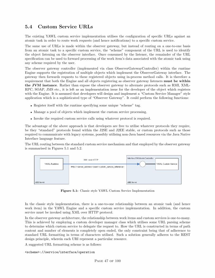
5.4 Custom Service URLs
The existing YAWL custom service implementation utilises the configuration of specific URLs against anatomic task in order to route work requests (and hence notifications) to a specific custom service.
The same use of URLs is made within the observer gateway, but instead of routing on a one-to-one basisfrom an atomic task to a specific custom service, the “scheme” component of the URL is used to identifythe object listening on the observer interface. Once consumed by the listener, the remainder of the URLspecification can be used to forward processing of the work item’s data associated with the atomic task usingany scheme required by the user.
The observer gateway controller (implemented via class ObserverGatewayController) within the runtimeEngine supports the registration of multiple objects which implement the ObserverGateway interface. Thegateway then forwards requests to these registered objects using in-process method calls. It is therefore arequirement that both the Engine and all objects registering as observer gateway listeners must be withinthe JVM instance. Rather than expose the observer gateway to alternate protocols such as RMI, XML-RPC, SOAP, JMS etc., it is left as an implementation issue for the developer of the object which registerswith the Engine. It is assumed that developers will design and implement a “Custom Service Manager” styleapplication which is a sophisticated type of “Observer Gateway”. It could perform the following functions:
• Register itself with the runtime specifying some unique “scheme” tag.
• Manage a pool of objects which implement the custom service processing.
• Invoke the required custom service calls using whatever protocol is required.
The advantage of the above approach is that developers are free to utilise whatever protocols they require,be they “standard” protocols found within the J2SE and J2EE stable, or custom protocols such as thoserequired to communicate with legacy systems, possibly utilising non-Java based resources via the Java NativeInterface language feature.
The URL routing between the standard custom service mechanism and that employed by the observer gatewayis summarised in Figures 5.1 and 5.2.
Figure 5.1: Classic style YAWL Custom Service Implementation
In the classic style implementation, there is a one-to-one relationship between an atomic task (and hencework item) in the YAWL Engine and a specific custom service implementation. In addition, the customservice must be invoked using XML over HTTP protocol.
In the observer gateway architecture, the relationship between work items and custom services is one-to-many.This is achieved by employing a custom developer manager class which utilises some URL parsing schemeto determine which custom service to delegate the request to. How the URL is constructed in terms of pathcontent and number of elements is completely open ended, the only constraint being that of adherence tostandard URL formatting in terms of characters utilised. Such a solution generally adheres to the RESTdesign principle, wherein each URI represent a particular resource.
A suggested URL formatting scheme is as follows:
<scheme>://service/interface/operation
Page 47 of 100

Figure 5.2: Observer Gateway YAWL Custom Service Implementation
The components are described in the following table:
Component Descriptionscheme This element defines the tag that links this URL to a specific
scheme of custom service manager. This is the value thatthe manager uses when registering itself with the runtimefor receipt of notifications on the observer gateway listenerinterface.
service Describes the service as offered by the target custom service.“Order Processing” is a suitable example.
interface Describes an interface (i.e. a collection of methods oroperations) as supported by the “service”. “Provisioning”is a suitable example.
operation Describes the operation of method to be called within the“interface”. “NewCreditOrder” is a suitable example.
5.5 Implementing the Manager Class
The use of a manager class is optional. Without an intermediate manager class, the object registering withthe observer gateway will need to directly implement the business logic required to consume and process allwork items where the URL associated with the workitem has the same URL “scheme” as that specified bythe registering observer gateway.
For example, the following work item requests will be forwarded to observer gateways which register with ascheme of “xyz”:
• xyz://sales/order/newOrder
• xyz://sales/order/cancelOrder
• xyz://inventory/stockitem/addNewStockItem
By making the registering Observer Gateway object a form of “manager”, work item requests can be analysedand the work delegated to some other object or even external system. The routing can be performed byparsing the full URL path defined against the work item, or even by inspection of the XML data associatedwith the work item (this being available once the work item has been checked-out of the runtime - and hencemoved from the “enabled” state to the “executing” state).
Page 48 of 100
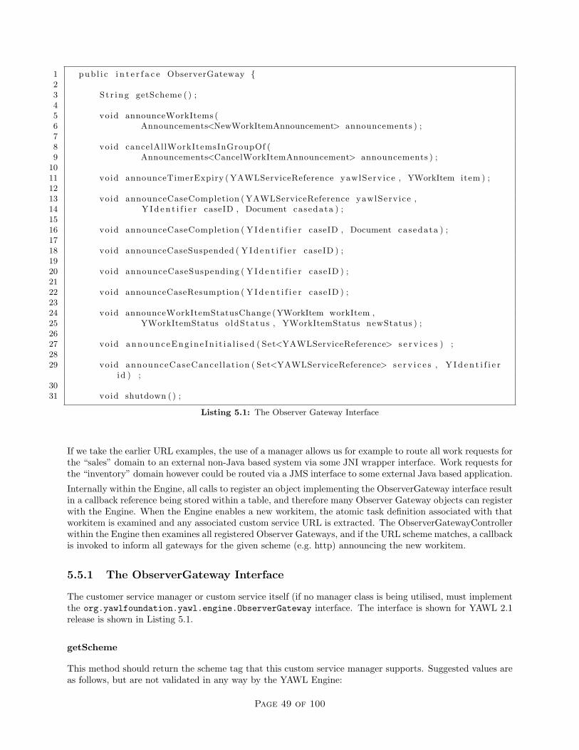
1 pub l i c i n t e r f a c e ObserverGateway {23 St r ing getScheme ( ) ;45 void announceWorkItems (6 Announcements<NewWorkItemAnnouncement> announcements ) ;78 void cancelAllWorkItemsInGroupOf (9 Announcements<CancelWorkItemAnnouncement> announcements ) ;
1011 void announceTimerExpiry ( YAWLServiceReference yawlServ ice , YWorkItem item ) ;1213 void announceCaseCompletion ( YAWLServiceReference yawlServ ice ,14 Y I d e n t i f i e r caseID , Document casedata ) ;1516 void announceCaseCompletion ( Y I d e n t i f i e r caseID , Document casedata ) ;1718 void announceCaseSuspended ( Y I d e n t i f i e r caseID ) ;1920 void announceCaseSuspending ( Y I d e n t i f i e r caseID ) ;2122 void announceCaseResumption ( Y I d e n t i f i e r caseID ) ;2324 void announceWorkItemStatusChange (YWorkItem workItem ,25 YWorkItemStatus o ldStatus , YWorkItemStatus newStatus ) ;2627 void announceEng ine In i t i a l i s ed ( Set<YAWLServiceReference> s e r v i c e s ) ;2829 void announceCaseCancel lat ion ( Set<YAWLServiceReference> s e r v i c e s , Y I d e n t i f i e r
id ) ;3031 void shutdown ( ) ;
Listing 5.1: The Observer Gateway Interface
If we take the earlier URL examples, the use of a manager allows us for example to route all work requests forthe “sales” domain to an external non-Java based system via some JNI wrapper interface. Work requests forthe “inventory” domain however could be routed via a JMS interface to some external Java based application.
Internally within the Engine, all calls to register an object implementing the ObserverGateway interface resultin a callback reference being stored within a table, and therefore many Observer Gateway objects can registerwith the Engine. When the Engine enables a new workitem, the atomic task definition associated with thatworkitem is examined and any associated custom service URL is extracted. The ObserverGatewayControllerwithin the Engine then examines all registered Observer Gateways, and if the URL scheme matches, a callbackis invoked to inform all gateways for the given scheme (e.g. http) announcing the new workitem.
5.5.1 The ObserverGateway Interface
The customer service manager or custom service itself (if no manager class is being utilised, must implementthe org.yawlfoundation.yawl.engine.ObserverGateway interface. The interface is shown for YAWL 2.1release is shown in Listing 5.1.
getScheme
This method should return the scheme tag that this custom service manager supports. Suggested values areas follows, but are not validated in any way by the YAWL Engine:
Page 49 of 100

jms Java Method Callrmi Remote Method Invocationhttp Hyper Text Transfer Protocoljms Java Message Servicesoap Simple Object Access Protocol
announceWorkItem
This method will be called by the YAWL Engine for new workitems where the scheme component of theservice URL associated with that work item matches getScheme() on an ObserverGateway. The invokationsupplies a reference to both the YAWL service URI together with the workitem, within the context of aNewWorkItemAnnouncement. The Announcements object is a container for Announcement objects, groupedby scheme.
cancelAllWorkItemsInGroupOf
This method will be called by the YAWL Engine whenever a previously announced work item for this serviceis cancelled. Again the call is only made where the scheme component of the task URL matches getScheme()on an Observer Gateway.
announceTimerExpiry
This method will be called by the YAWL Engine whenever a work item timer expires.
announceCaseCompletion - with Service Reference
Upon launching a case the caller may elect any Custom YAWL Service to be notified once the case is complete.When doing so, this method gets called by the runtime once the case has completed. As usual, the call isonly made for ObserverGateway instances where the scheme component of the URL matches getScheme().The call supplies a reference to the YAWL service from which the URL can be obtained, together with a caseID, and the output case data.
announceCaseCompletion - without Service Reference
This version of the case completion method is called for cases where a completion listening service is notspecified.
announceCaseCancellation
This method is called by the Engine to announce when a case is cancelled.
announceCaseSuspending
This method is called by the Engine to announce when a case starts to suspend (i.e. enters the ’suspending’state as opposed to entering the fully ’suspended’ state).
announceCaseSuspended
This method is called by the Engine to announce when a case suspends (i.e. becomes fully suspended asopposed to entering the ’suspending’ state).
Page 50 of 100

1 YEngine eng ine = YEngine . g e t In s tance ( f a l s e ) ;2 eng ine . r eg i s te r Inte r faceBObserverGateway ( t h i s ) ;
Listing 5.2: Dynamically registering an Observer Gateway instance
announceCaseResumption
This method is called by the Engine to announce when a case resumes from a previous ’suspending’ or’suspended’ state.
announceWorkItemStatusChange
Notifies a change of status for a work item.
announceEngineInitialised
This method is called by the Engine to advise that it has completed its initialisation routines and is in a’running’ state.
shutdown
This method is called when the Engine is shutdown (i.e. when its servlet is destroyed); the observer gatewayshould use this notification to do its own finalisation processing.
5.6 Registering with the YAWL Engine
Any custom service or custom service manager instance needs to register itself with the Engine once it hascompleted its initialisation and is ready to accept requests. There are two way to register an observer gatewayinstance with the Engine:
1. In the Engine’s web.xml file, enabling the ObserverGateway context parameter (it is commented out bydefault) and providing the fully qualified class name of the observer gateway instance as the parameter’svalue. Note that several observer gateways can be specified here, with each fully qualified class nameseparated by semi colons (;).
2. The object which implements the ObserverGateway interface needs to obtain a reference to the YAWLEngine and invoke the registration method as shown in Listing reflst:regObsGateway.
Once registered, the object will receive notifications for work items as they are generated. It should be notedthat work items already posted against the customer service will not be re-notified, it being the responsibilityof the manager to retrieve any outstanding work items and re-process these if required. To avoid such asituation, a reliable messaging framework such as JMS could be utilised to ensure requests in the form ofmessages are delivered to the target custom services, and avoid any requirement to re-post messages after arestart of the YAWL runtime and/or custom service manager instances.
Page 51 of 100

Page 52 of 100
Chapter 6
The Resource Service
to be done. . .
53

Page 54 of 100

Chapter 7
The Worklet Service
to be done. . .
55

Page 56 of 100

Chapter 8
The Editor
8.1 Introduction
This chapter describes the technical aspects of the YAWL Editor (currently at version 2.1). Knowledge ofJava, UML and the semantics of YAWL is assumed. The chapter is intended to give the reader an introductionand insight into to the editor’s design. While the reader may find some features of the editor’s design andimplementation somewhat “odd”, they are nevertheless that way for sound reasons. Many are legacy conceptsfrom the initial desire to build a quick prototype.
8.2 Foundations
The editor has been written in such a way that the core graphing library, JGraph, forms the very heart of theapplication. A decision to replace the core graphing library is a decision to rewrite the editor from scratch.Its reach goes too far, and is too tightly coupled to the rest of the code for the editor to be consideredanything other than an “application of JGraph”.
Section 8.2.1 covers the motivation for, and basics of using JGraph. Section 8.2.2 gives a high-level tour ofthe Java packages of the editor, introducing the nature of classes that are to be found in each package andhighlights packages of particular importance. Section 8.2.3 introduces how the base JGraph library has beenextended to achieve the YAWL editor’s key graphing functionality. Section 8.2.4 describes interesting aspectsof the editor’s build script.
8.2.1 JGraph
At the inception of the YAWLEditor project, a number of desired requirements for the editor were listed bythe drivers of the project. The editor was to be:
• freely available,
• runnable heterogeneously,
• easy to develop,
• inter-operate easily with the YAWL Engine,
• easy to deliver and run.
The greatest impediment to delivering a prototype IDE for YAWL was that of an adequately powerfulgraphing library. The project could only show quick outcomes by relying on a third-party graphing librarythat also enabled these requirements.
57

At the time, the JGraph drawing package was the only package to meet these requirements from the perspec-tive of a drawing environment for YAWL. A close second was the GEF drawing framework that comes withthe Eclipse IDE. The final decider against GEF, however, was the requirement that the editor be a plugin toEclipse, and that users of the editor would need Eclipse as a base environment to run within. The authors ofGEF stated at the time that it might be possible to run GEF independently of Eclispe, but that those whowere to try were on their own if they encountered problems. While building standalone Eclipse applicationsis now commonplace, at the time of the original design of the editor (2004), it was decided that JGraph wasthe better approach.
The requirements are re-listed below with a brief description per requirement of JGraph’s match to therequirement:
Freely available: Written in Java, released under LGPL. There were no runtime environment licensingcosts for the language, and the library was free to use in programming efforts so long as the LGPLrequirements were respected.
Runnable heterogeneously: Java programs allows a high likelihood that they will run with little tono changes on different operating systems with compatible JREs. Also, few heterogeneous languagesbesides Java and C# had a rich enough GUI environment to be considered viable.
Easy to develop: Again, Java is one of the best supported programming languages in terms of learningand adoption. Though the library was not exactly easy to develop with, it was the only free stand-aloneJava library being actively supported at the time.
Inter-operate easily with the YAWL Engine: The engine was written in Java, and to leverage as muchof what the engine had to offer as possible, the path of least effort was to call engine API methods inthe same language.
Easy to deliver and run: JGraph could be incorporated into an application to produce a standalone Javaapplication. GEF, which shared many of the above requirements until this point required the EclipseIDE to run, and expected an application using GEF to be written as an Eclipse plugin. At the time,this was not a trivial exercise to accomplish. Opinion by the project owners at the time was that theyalso disliked the idea of requiring such a large IDE as a pre-requisite for trying the editor.
JGraph can be a difficult library to understand initially. The reader is directed to the JGraph tutorial foran official discussion of the framework. Below is a brief, bottom-up description of the environment. A smallclass diagram of the “‘core” JGraph model primitives1 is supplied in figure 8.1.
A graphing package at its heart is a convenience package allowing a user to easily connect a set of nodes withlines. In JGraph, a node is made by implementing the abstract GraphCell interface, and a line an Edge.The only way to connect an edge to a node is via another type of cell called a Port. (Nodes, edges and portsare all subtypes of the GraphCell interface). A port must be a child of a node. Thus, to connect one nodeto another with an edge, you do so via connecting that edge to a child port for each of the nodes. Figure 8.2illustrates this relationship with a concrete example.
In figure 8.2, two tasks are connected to each other with a flow. The tasks are YAWLVertex objects thatimplement the GraphCell interface. The flow is an extension of Edge interface. The edge is selected, makingvisible the ports connecting the edge to the boundaries of the relevant tasks.
JGraph is an implementation of the MVC (Model-view-controller) software design pattern. An implementa-tion of this pattern requires a model object, a controller object, and a number of view objects. Very basicversions of each type of class are supplied via DefaultGraphModel, JGraph and GraphLayoutCache for themodel, controller and views, respectively. Implementations of the interfaces listed in figure 8.1 must be placedwithin a DefaultGraphModel, to be considered part of that graph.
An important conceptual note must be made here on how to appropriately use JGraph:
1Even then, this is not a faithful representation of the true relationships of classes within JGraph, but does act as a goodmodel of how to view how you’d typically consider these key classes to interact.
Page 58 of 100
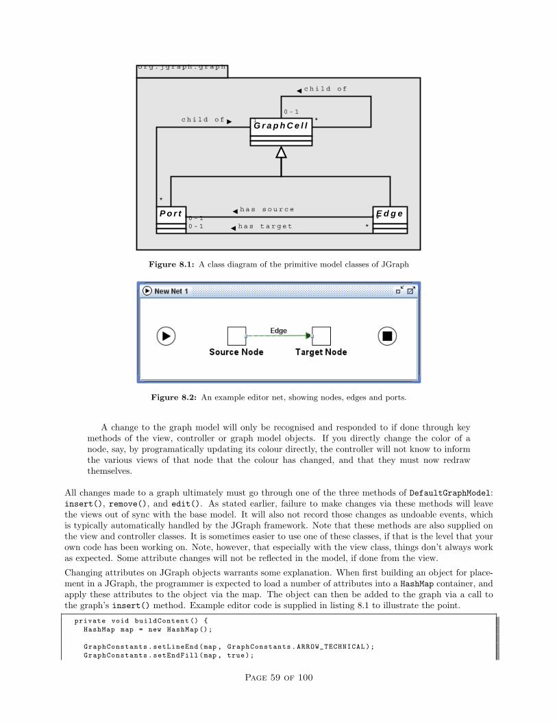
o r g . j g r a p h . g r a p h
G r a p h C e l l
E d g eP o r t
c h i l d o f
*
1
c h i l d o f
0 - 1*
h a s s o u r c e*0 - 1
h a s t a r g e t *0 - 1
Figure 8.1: A class diagram of the primitive model classes of JGraph
Figure 8.2: An example editor net, showing nodes, edges and ports.
A change to the graph model will only be recognised and responded to if done through keymethods of the view, controller or graph model objects. If you directly change the color of anode, say, by programatically updating its colour directly, the controller will not know to informthe various views of that node that the colour has changed, and that they must now redrawthemselves.
All changes made to a graph ultimately must go through one of the three methods of DefaultGraphModel:insert(), remove(), and edit(). As stated earlier, failure to make changes via these methods will leavethe views out of sync with the base model. It will also not record those changes as undoable events, whichis typically automatically handled by the JGraph framework. Note that these methods are also supplied onthe view and controller classes. It is sometimes easier to use one of these classes, if that is the level that yourown code has been working on. Note, however, that especially with the view class, things don’t always workas expected. Some attribute changes will not be reflected in the model, if done from the view.
Changing attributes on JGraph objects warrants some explanation. When first building an object for place-ment in a JGraph, the programmer is expected to load a number of attributes into a HashMap container, andapply these attributes to the object via the map. The object can then be added to the graph via a call tothe graph’s insert() method. Example editor code is supplied in listing 8.1 to illustrate the point.
private void buildContent () {
HashMap map = new HashMap ();
GraphConstants.setLineEnd(map , GraphConstants.ARROW_TECHNICAL);
GraphConstants.setEndFill(map , true);
Page 59 of 100

GraphConstants.setLineStyle(map , GraphConstants.STYLE_ORTHOGONAL);
GraphConstants.setBendable(map , false);
GraphConstants.setEditable(map , true);
GraphConstants.setDisconnectable(map , true);
GraphConstants.setConnectable(map , true);
getAttributes ().applyMap(map);
setPredicate("true()");
setPriority (0);
}
Listing 8.1: Setting attributes on a model object
Listing 8.1 shows code for setting key attributes of flow relations, which are a kind of edge within YAWL. TheGraphConstants class is used to ensure that the hashmap is built only with type-safe data that is compatiblewith a given attribute.
Note also that a great deal of the API for JGraph requires that arrays of the most basic Java Object bepassed around. The JGraph tutorial lists a number of reasons why they feel this is a necessary part of theframework. However, as a user of the framework, one should be careful not to come to grief by finding objectsof an unexpected class mixed into a return set. Another side-effect of this is the large amount of class-castingcode required on the boundaries between the editor code and the JGraph library.
Though there is a great deal more to the framework in terms of constructing views, listening for events, andthe like, a discussion on such aspects is left until we actually describe key extensions made for YAWL. Ona final note for JGraph, the reader is urged to familiarise themselves with the JGraph FAQ, and to becomefamiliar with JGraph’s forums for further support.
8.2.2 Package Contents
This section briefly describes the Java package hierarchy of the YAWLEditor, giving a basic guide to what aprogrammer may expect to find in any given editor source package. Any Java code that belongs specificallyto the editor will reside in a sub-package of the base editor package org.yawlfoundation.yawl.editor.We assume that this package is reserved specifically for editor code. This base editor package deliberatelycontains only two classes:
YAWLEditor.java: The bootstrap class that starts the editor running.
TestYAWLEditor.java: This is the core JUnit test class that binds all other JUnit test classes for the editorso that they may be executed as a single unit test.
Figure 8.3 lists the current Java packages that makes up the core editor code, and briefly describes thenature of the classes to be found in each package. If there is a “key” package of the editor, containing classesthat do the core job of graph manipulation, that package is org.yawlfoundation.yawl.editor.net. On adarker note, if there is anywhere in the editor where classes have tended toward implementing the god objectanti-pattern, this this is the package for the very worst examples.
Another important package is org.yawlfoundation.yawl.editor.specification. This package, however,is focused on managing an entire specification. There is very little code specific to graphing in this package,but the classes here are responsible for saving and loading a specification, and managing specification-wideevents.
In later sections, key classes from both packages will be described in much more detail.
8.2.3 Extensions to JGraph
With a basic understanding of how JGraph works from section 8.2.1, we now describe how the basic frameworkof JGraph has been extended to implement the YAWLEditor. This section describes passive elements in
Page 60 of 100

Figure 8.3: The Java package hierarchy of the editor
section 8.2.3 and active elements in section 8.2.3 depending on whether they need further processing, or areresponsible for the processing, respectively.
Page 61 of 100

Passive Graphing Elements
Figure 8.4 is a class diagram showing how the graphing model constructs of JGraph (see figure 8.1) havebeen extended to implement the YAWLEditor graphing model. These constructs reside in the packageorg.yawlfoundation.yawl.editor.elements.model. The package is passive in the sense that it’s notenough to just change attributes on objects in the package and have the change work. The changes must beprocessed through an active component, described later.
o r g . y a w l f o u n d a t i o n . y a w l . e d i t o r . e l e m e n t s . m o d e l
o r g . j g r a p h . g r a p h
V e r t e x C o n t a i n e rV e r t e x L a b e l0 . . 1 1
D e f a u l t G r a p h C e l l
< < I n t e r f a c e > >
Y A W L C e l l
Y A W L V e r t e x Y A W L F l o w R e l a t i o n
D e f a u l t E d g e
Y A W L P o r t
D e f a u l t P o r t
D e c o r a t o r P o r t
Y A W L C o n d i t i o n
I n p u t C o n d i t i o n C o n d i t i o n O u t p u t C o n d i t i o n
D e c o r a t o r
S p l i t D e c o r a t o r J o i n D e c o r a t o r
1
0 . . 1
0 . . 1 1
5
1
0 . . 1
1
Y A W L T a s k
C o m p o s i t e T a s k A t o m i c T a s k
M u l t i p l e A t o m i c T a s kM u l t i p l e C o m p o s i t e T a s k
< < I n t e r f a c e > >
Y A W L C o m p o s i t e T a s k
< < I n t e r f a c e > >
Y A W L M u l t i p l e I n s t a n c e T a s k
3 . . 4
1
< < I n t e r f a c e > >
P o r t< < I n t e r f a c e > >
E d g e< < I n t e r f a c e > >
G r a p h C e l l
Figure 8.4: A class diagram of the graph model of the YAWLEditor
A few features of figure 8.4 need discussion. We can see from the class diagram that a number of classesinherit from DefaultGraphCell. The most important of these from a design perspective is YAWLVertex. Theother three inherited classes (being VertexLabel, VertexContainer and Decorator) play a subservient roleto YAWLVertex. For example, if a VertexContainer exists, it can only do so if it contains a YAWLVertex.Though other constructs can be contained within a VertexContainer, they are all optional, and very muchdepend on the existence of the vertex to have any meaning.
Note that the concept of a VertexContainer, and explicit Decoratorator classes for splits and joins wasa conscious design decision. An alternative was to have tasks contain all split and join behaviour. Thisalternative would have been a more natural fit to the engine native XML file format where there is noconcept of a decorator for a task to describe a split or a join. After some consideration, it was felt that thecomplexity of a single Task object (especially view objects, described later) would be too high, and involvefar too much coupling to a task’s model and view objects, if it were also to contain split and join logic.
Figure 8.5 shows a concrete example of a VertexContainer, containing an AtomicTask instance, a SplitDecorator,a JoinDecorator and a VertexLabel. The container has been selected, and its boundary is currently visible
Page 62 of 100

for the purpose of manipulating the entire set of components within it as a single entity. The container’spurpose is to hold together a number of graph constructs that need to be considered a single conceptualentity by a workflow designer. Again, it should be stressed that without the AtomicTask, there is no purposeto the other constructs that have been bound to it.
Figure 8.5: A concrete example of a VertexContainer binding task elements together.
Note also from figure 8.4, that there are a number of ports bound to certain key objects. A design decisionwas made to have a number of ports per net graph element, to be positioned along an appropriate boundaryof the graph element. The alternative considered was to have a single port at the centre of a node whereall flows for that node could be connected, which is more in keeping with packages such as Microsoft Visio.This Visio-style approach has also been occasionally asked for in the past. Two insights led the the approachconstructed:
• Splits and joins in YAWL overlap in their representative icons. A single port would allow a great dealof ambiguity over the kind of split or join that a task had (a flow could be drawn running into anor-split, for example, which is also drawn the same way as an or-join). It was decided that to force onlyoutgoing flow from splits, and incoming flows to joins, thus removing a degree of possible confusionaround splits and joins.
• The mechanics for having a flow connect to the center of a node, but only drawn to its edge breaksdown when a task has a split and a join on adjacent edges. The bounding-box of the entire task elementset, including the split and join has a small square of whitespace between the two decorators, and flowswould run only to the edge of this whitespace. The result would be a flow that seems to stop short ofthe task to which it’s connected.
Conditions and tasks both have sub-trees of inheritance from YAWLVertex and each encode their own specificrequired model constraints. Note that the class hierarchy depicted in figure 8.4 introduces a set of methodsthat allows a particular class to answer questions about what may validly be done with it, meaning that as faras possible, rules are localised to the class involving them. For example, a standard Condition allows bothincoming and outgoing flows. If you were to ask an InputCondition, however, if it allowed incoming flows,it would answer in the negative. The reader is directed to the interface YAWLCell for a set of basic methodsthat all tasks, conditions and flow relations must implement. Further interfaces (see YAWLCompositeTask forexample) deeper in the hierarchy introduce more specialised methods to enforce requirements particular tocertain workflow elements.
The corresponding views of the model objects described above can also be viewed as passive. They simplydraw on the screen a representation of their corresponding model object equivalents. Figure 8.6 is a classdiagram mapping key model classes from figure 8.4 to the view classes responsible for their rendering. Theview classes required reside in the package org.yawlfoundation.yawl.editor.elements.view.
We note from figure 8.6 that ports, flow relations and vertex containers need no special rendering, andfall back to the basic view classes supplied by JGraph. Other net elements need their own views specified,however. Note the special case of the Decorator and DecoratorView pair. Instances of SplitDecorator andJoinDecorator are ultimately what are placed on the canvas of a Net graph. However, there is significant
Page 63 of 100

o r g . y a w l f o u n d a t i o n . e d i t o r . e l e m e n t s . v i e w
o r g . y a w l f o u n d a t i o n . e d i t o r . e l e m e n t s . m o d e l
A t o m i c T a s k
M u l t i p l e A t o m i c T a s k
C o m p o s i t e T a s k
M u l t i p l e C o m p o s i t e T a s k
I n p u t C o n d i t i o n
O u t p u t C o n d i t i o n
C o n d i t i o n
D e c o r a t o r
V e r t e x C o n t a i n e r Y A W L P o r tY A W L F l o w R e l a t i o n
o r g . j g r a p h . g r a p h
E d g e V i e w V e r t e x V i e w
1
1
1
1
A t o m i c T a s k V i e w
M u l t i p l e A t o m i c T a s k V i e w
C o m p o s i t e T a s k V i e w
M u l t i p l e C o m p o s i t e T a s k V i e w
I n p u t C o n d i t i o n V i e w
O u t p u t C o n d i t i o n V i e w
C o n d i t i o n V i e w
D e c o r a t o r V i e w
P o r t V i e w
1
1
1
1
1
1
1
1
1
1
1
1
1
1
1
1
1
1
o r g . y a w l f o u n d a t i o n . e d i t o r . n e t
N e t G r a p h N e t C e l l V i e w F a c t o r y
D e f a u l t G r a p h L a y o u t C a c h e
s u p p l i e s v i e w s f o r
1
1
u s e s t o r e n d e r o v e r a l l v i e w
1
1
* *
*
*
*
*
c r e a t e s
1
**
* *
c r e a t e s
1
*
*
*
*
*
*
*
*
*
*
c r e a t e s a m a t c h i n g v i e w f o r m o d e l o b j e c t1
*
Figure 8.6: A class diagram of how model objects are associated with their views
overlap in how splits and joins graphically represent whether they are OR, XOR, or AND types. Rather thanrepeat the same rendering code in two classes, the one view object deals with both types of decorator.
JGraph requires that a special type of class be supplied to the view component of the graph that acts asan implementation of the factory pattern. This class is to take model objects, and return correspondingview object for them, and is ultimately invoked by the JGraph view component. We also see from thisfigure that we need no special view component for the actual graph of a YAWL net. The JGraph suppliedDefaultGraphLayoutCache suffices, so long as it has an instance of NetCellViewFactory set as its viewfactory.
Active Graphing Elements
The package org.yawlfoundation.yawl.editor.net could be considered the heart of the editor. Specificallythe two classes NetGraph and NetGraphModel from this package are where the real action for drawing YAWLnets is to be found. Figure 8.7 is a class diagram of the core net package classes and their relationship to eachother. The reader should see almost immediately that all roads lead to NetGraph. Following close behindthis class in terms of importance to editor behaviour is the class NetGraphModel.
A note should be made on cancellation sets, and their implementation. Every atomic task can potentiallyhave its own cancellation set. However, only one cancellation set can be rendered on the graph at anyone time. When that cancellation set is viewable, CancellationSetModel allows additions and removal ofelements from the relevant cancellation set. We have one CancellationSetModel per NetGraph, though theactual cancellation set this model manipulates can change with user selection.
Figure 8.8 shows the cancellation set of task a being rendered in red. As a is the cancellation set triggeringtask, its background is grey. Whilst the cancellation region of a is visible, extra tooltip buttons becomeenabled, allowing the user to change the composition of this cancellation set. This is a deliberate designchoice that varies somewhat from the “lasso” approach described in the YAWL research publications. Thelasso concept proved be difficult to implement, especially when some tasks in a rectangular region of a lassomay not be part of the cancellation set.
There are also a number of classes that register as mouse and keyboard listeners with NetGraph to handlevarious functionality triggered by these forms of input. Most of these classes are rather trivial, and quickly
Page 64 of 100

o r g . y a w l f o u n d a t i o n . y a w l . e d i t o r . n e t
C a n c e l l a t i o n S e t
C a n c e l l a t i o n S e t M o d e l
< < I n t e r f a c e > >
C a n c e l l a t i o n S e t M o d e l L i s t e n e r
l i s t e n s t o c h a n g e s i n
*
1
v i s i b i l i t y m a n a g e d b y
*
1
N e t G r a p h
N e t G r a p h M o d e l
E l e m e n t C o n t r o l C l i c k L i s t e n e r
E l e m e n t D o u b l e C l i c k L i s t e n e r
N e t P o p u p L i s t e n e r
N e t M a r q u e e H a n d l e r
N e t S e l e c t i o n L i s t e n e r
o r g . y a w l f o u n d a t i o n . y a w l . e d i t o r . n e t . u t i l i t i e s
N e t C e l l F a c t o r y
N e t C e l l U t i l i t i e s
N e t U t i l i t i e s
h a n d l e s m o u s e p a l e t t e e v e n t s f o r1
*h a n d l e s m o u s e C T R L - c l i c k e v e n t s f o r1 *
h a n d l e s m o u s e d o u b l e - c l i c k e v e n t s f o r1
*
h a n d l e s m o u s e p o p u p - m e n u e v e n t s f o r1
*
c r e a t e s c e l l s w i t h i n
1
*
+ M V C C o n t r o l l e r
1
+ M V C M o d e l
1
s u p p l i e s u t i l i t y m e t h o d s f o r c e l l s i n
*
1
s u p l i e s u t i l i t y m e t h o d s f o r
*
1
h a n d l e s s e l e c t i o n e v e n t s i n1
*
m a n a g e s t h e c u r r e n t l y v i s i b l e c a n c e l l a t i o n s e t f o r1
1
Figure 8.7: A class diagram of the core net package
understandable with a perusal of the actual code. One, however, is rather complex, and deserves furtherdiscussion.
This class is NetMarqueeHandler, and is responsible for dealing with basic drawing on the graph, taking intoaccount a number of factors, such as the currently selected palette button, and the type of element the mousewas hovering over when a user began using the mouse on the graph. The key behaviour of this class is torecognise and react to mouse events for placing tasks and conditions on the graph, to allow flows to be drawnbetween valid net elements, and to allow for the selection of a number of elements for further processing.
Earlier versions of the editor required a “flow” palette button that had to be selected to allow flows to bedrawn between elements. Several users mentioned that they wished to draw flows without having to selectthe palette button, however. Texts on UI design2 also suggest that removing modal behaviour, such asexplicitly requiring a flow palette button to be depressed for drawing a flow, be removed where possible.Thus, NetMarqueeHandler underwent an overhaul, and implemented a state transition machine that allowedthe user to draw flows if their mouse was over a valid port, to drag an element if over the element, or drop anew element onto the graph canvas if there is nothing under the mouse. The state transition diagram usedto initially design the desired change in marquee behaviour is shown in figure 8.9. It is suppled here in thehopes of allowing a quick understanding of the state transition machine built into NetMarqueeHandler.
2See “The Humane Interface” by Jef Raskin for one of the better explanation on why modal UI behaviour is to be avoidedwhere possible.
Page 65 of 100

Figure 8.8: A visible cancellation set in the editor
Over Vertex[overVertex]
mouseMoved()
Over Outgoing Port[overOutgoingPort]
mouseMoved()
Dragging VertexmousePressed()
Idle
[overNothing]
mouseMoved()
[overNothing]
mouseMoved()
Drawing FlowmousePressed()
mouseDragged()
mouseDragged()
mouseReleased()
mouseReleased()
Figure 8.9: A state transition diagram for NetMarqueeHandler
8.2.4 Build Environment
This section describes the build environment used to create an executable editor, along with issues thatdevelopers should be aware of when having to make changes to this build environment. The editor has anant build script, which sits within the the source directory of the editor. All of the resources required by thisscript are expressed in terms of relative paths to the script. It’s thus possible to decompress the source zipfile anywhere, and expect to have the ant script produce runnable editor jar files. The script has a numberof targets, listed below with a brief description of the result when running the script with a given target:
buildEditorComplete: Compiles, builds and packages a complete YAWLEditor.jar. This target requiresthe YAWL Engine’s standalone jar in the project’s lib directory.
buildEditorLite: Compiles, builds and packages a “lite” version of the editor, containing just core editorand JGraph code. A lite editor requires the YAWL Engine’s standalone jar on its classpath, or will
Page 66 of 100

have all behaviour relying on the engine deactivated if it cannot find it.
clean: Resets the build environment to just the source, tool and library directories. This target should berun whenever the YAWL Engine’s standalone jar is updated in the project’s lib folder.
compile: Compiles the editor source, by compiling the core YAWLEditor.java class. This will not compileJUnit tests, as the editor does not reference the unit test classes. Part of the work here involves creatinga compiled directory containing all resources that should be packed into a standalone jar file.
compileTestFiles: Compiles the editor’s JUnit source code, and all the editor code that the JUnit codeexercises.
document: Generates javadoc from the editor source code.
full: A convenience target, that invokes the clean target, then builds a lite editor, a complete editor,zipped source code and javadoc.
release: A convenience target, that builds a lite editor, a complete editor, zipped source code and javadocready for release.
runTests: Runs JUnit on the compiled JUnit test classes.
zipSourceCode: Generates a zipped source file image, and automatically filtered release notes and changelog, all ready for minimal-fuss delivery to sourceforge.
Note the existence of the file build.properties residing in the same directory as the ant build script. Thebuild script uses this properties file to identify current version values and dependencies the editor has onother technologies. The properties file is also used to apply filter across the editor source code, replacingplaceholder text with actual text spread throughout the editor text for the current build (such a releasenumbers, etc.).
There are two sibling directories to the source directory that are important for generating an executableeditor. These directories are lib, which contains the standalone engine jar and other required 3rd partylibraries, and tools, which currently contains the JUnit jar. Build file deliverables, such as jar files orsource zip files, are output to the project’s distribution directory, created as a sibling to the sourcedirectory.
When it comes to actually building the editor, one can choose a “lite” or complete version of the editor.The original rationale for a “lite” editor stems from original design belief that the editor and engine shouldremain as decoupled as possible. A lite editor allows one to quickly ascertain whether the editor will functionas intended, even without access to the engine. More will be said on coupling between the editor and enginein later sections.
8.3 Superstructure
This section describes superstructure of the editor, which uses features described in section 8.2 as the necessaryoperational basis for the behaviour described here. Behaviour is named “superstructure”, because in a veryreal sense, this behaviour relies on the behaviour already described in this earlier section.
This section is broken into a number of subsections. Section 8.3.1 deals with various aspects to specificationmanagement. Section 8.3.2 describes the typical approach that has been taken to interfacing with 3rd-partysoftware. Section 8.3.3 briefly describes Swing undo/redo functionality extensions that were needed aboveand beyond basic JGraph undo/redo behaviour. Section 8.3.4 describes the general approach taken to JUnittesting of the editor.
Page 67 of 100

8.3.1 Specification Management
Section 8.2.3 covered editor behaviour that involved manipulating a single net’s graph. A specification iscomposed of several nets, however. This section describes key editor behaviour for manipulating a speci-fication. Note that the editor can currently edit only a single specification at a time. This was a designdecision taken early in the life of the editor in order to achieve a usable prototype as quickly as possible.Since then, the desire for editing several specifications has been raised time and again, and will be addressedin an upcoming version. Most of the core model behaviour for specifications described here resides withinthe package org.yawlfoundation.yawl.editor.specification.
Figure 8.10 is a class diagram of the key classes in the specification package. Associations with classes inrelated packages are shown where it was thought appropriate.
o r g . y a w l f o u n d a t i o n . y a w l . e d i t o r . s p e c i f i c a t i o n
o r g . y a w l f o u n d a t i o n . y a w l . e d i t o r . t h i r d p a r t y . e n g i n e
S p e c i f i c a t i o n M o d e l
S p e c i f i c a t i o n F i l e M o d e l
A r c h i v i n g T h r e a d
S p e c i f i c a t i o n A r c h i v e H a n d l e r
Y A W L E n g i n e P r o x y
1
1 s u p p l i e s a d e v o t e d I / O t h r e a d f o r1
1
< < I n t e r f a c e > >
S p e c i f i c a t i o n F i l e M o d e l L i s t e n e r
l i s t e n s f o r k e y f i l e - b a s e d e v e n t s o f
*
1
h a n d l e s f i l e e v e n t s f o r
1
1 s a v e s a n d l o a d s
1
1
e n a b l e s e x p o r t , i m p o r t , v a l i d a t i o n a n d a n a l y s i s o f
1
1
< < I n t e r f a c e > >
S p e c i f i c a t i o n M o d e l L i s t e n e r
l i s t e n s f o r s t a t e c h a n g e s i n
*
1S p e c i f i c a t i o n U t i l i t i e s
p r o v i d e s u t i l i t i e s f o r
1
1
S p e c i f i c a t i o n U n d o M a n a g e r
m a n a g e s u n d o / r e d o g r a p h e v e n t s f o r
1
1
b l o c k s m u l t i p l e I / O a t t e m p t s v i a
1
1
S p e c i f i c a t i o n S e l e c t i o n L i s t e n e r< < I n t e r f a c e > >
S p e c i f i c a t i o n S e l e c t i o n S u b s c r i b e r
r e c e i v e s s e l e c t i o n e v e n t s o f i n t e r e s t f r o m
* 1
o r g . y a w l f o u n d a t i o n . y a w l . e d i t o r . n e t
N e t G r a p h
c o n t a i n s
1 +
1
N e t S e l e c t i o n L i s t e n e r
d e l e g a t e s s e l e c t i o n e v e n t p r o c e s s i n g t o1 +
1
r e c e i v e s s e l e c t i o n e v e n t s f r o m
1
1
Figure 8.10: A class diagram of the core specification package
State Management
The two core specification package classes SpecificationModel and SpecificationFileModel operate asstate transition machines that listeners can react to upon key state change events.
State transition in SpecificatioModel is rather trivial. There are two main states that it toggles between,namely NO NETS EXIST and NETS EXIST. The first of these states happens only briefly on a reset of a spec-ification model, as a valid specification must always have at least a root net. A number of events are alsooccasionally fired from this class, but are not states as such, just event notifications that state listeners mayalso care to know about. These events are NO NET SELECTED, SOME NET SELECTED, and NET DETAIL CHANGED.Classes that implement the SpecificationModelListener interface will be notified of these events, and reactas they deem most appropriate.
State transition in the class SpecificationFileModel is a little more involved. A state transition diagramof it is supplied in figure 8.11.
State transition in SpecificationFileModel is one the few areas of the editor that caters for the possibilityof having several specifications open. Again, there are two key states, being IDLE and EDITING representing
Page 68 of 100

S p e c i f i c a t i o n F i l e M o d e l
I D L E E D I T I N G
B U S Y
i n c r e m e n t F i l e C o u n t ( )[ f i l eCoun t > 1 ]
i n c r e m e n t F i l e C o u n t ( )
[ f i l eCoun t > 1 ]
d e c r e m e n t F i l e C o u n t ( )[ f i l e C o u n t = = 1 ]
d e c r e m e n t F i l e C o u n t ( )
b u s y ( ) b u s y ( )
H
n o t B u s y ( )
Figure 8.11: A STD describing SpecificationFileModel behaviour
an editor with no specifications open, and an editor with at least one specification open, respectively. A thirdstate, BUSY can be reached at any time from either state. Once the model stops being busy, it reverts towhatever state it was previously in. Whenever SpecificationFileModel is busy, it is essentially blocking,allowing a devoted file I/O thread class ArchivingThread exclusive access to the filesystem, for the purposeof writing or reading files. Classes implementing SpecificationFileModelListener are expected to disallowany behaviour whilst in the busy state that might interfere with the file operations currently underway. FileI/O is regulated to a dedicated thread to allow the user to continue using the editor on long file operations.
A third state management class, SpecificationSelectionListener has all net selection events delegatedto it. In reality only a single net will ever be generating selection events, but no matter which net is currentlyhaving nodes selected, events will pass from the net selection listener to this class for processing. This classtakes the currently selected set of nodes and interrogates them for patterns of selection that are of interestto listeners implementing the SpecificationSelectionSubscriber interface. Listeners can subscribe to beinformed of a number of patterns that they may wish to react to. The current set of possible patterns testedfor are listed below, and are hopefully self-explanatory:
• STATE NO ELEMENTS SELECTED
• STATE COPYABLE ELEMENTS SELECTED
• DELETABLE ELEMENTS SELECTED
• STATE ONE OR MORE ELEMENTS SELECTED
• STATE MORE THAN ONE ELEMENT SELECTED
• STATE MORE THAN ONE VERTEX SELECTED
• STATE SINGLE TASK SELECTED
• STATE SINGLE ELEMENT SELECTED
Behaviour across the various aspects of the editor is only valid when one or more of the above patternsof selection are true. Such behaviour will implement the previously mentioned interface and subscribe forpatterns where that behaviour can be applied. For example, input conditions and output conditions cannotbe deleted or copied from a net. If a selection in a net selects only an input condition, the copy menu itemwill know that it has nothing to copy, and stay disabled until such time as a selection event includes netelements that can be copied.
Saving and Loading
The class SpecificationArchiveHandler is responsible for saving and loading YAWL specification files.Prior to version 2.0, an editor save file (ywl file) was, quite literally, an XML serialization of specification
Page 69 of 100

model objects that has been compressed using the popular Winzip compression algorithm. It is thus possibleto open an ywl file with Winzip or some other compatible compression utility and interrogate the XMLrepresenting the sate of model objects in the editor at save-time. Since 2.0, these serialized files have beendeprecated, and all loading and saving is done to and from yawl files in plain-old-XML (POX) format.
As a legacy of the pre-2.0 file serialization formats, each class that was serialized as part of the editor save/loadroutine uniformly stores its data members in a HashMap called serializationProofAttributeMap. Withoutthis approach to saving and loading object attributes, the addition of a new attribute to a class would breaksave-file backward compatibility, stopping the editor from successfully loading older specifications that donot have a newly introduced object attribute. Note also that JGraph employs a similar technique for its coregraphing elements.
Listing 8.2 shows example code to highlight the way in which state is expected to reside as attributes inthese model objects. As they were ultimately to be processed by the Java classes java.beans.XMLEncoderand java.beans.XMLDecoder, all state saved and loaded needed to conform to those parts of the Java Beanstandard needed by these XML utilities. Specifically, a class needs a no-argument constructor, which will beinvoked when the class is initially de-serialized, and a get()/set() method pair for each attribute that theywish to serialize.
private HashMap serializationProofAttributeMap = new HashMap ();
...
public void setSerializationProofAttributeMap(HashMap map) {
this.serializationProofAttributeMap = map;
}
public HashMap getSerializationProofAttributeMap () {
return this.serializationProofAttributeMap;
}
....
// example serialization -proof attribute bean methods below.
public void setSize(Dimension size) {
serializationProofAttributeMap.put("size",size);
}
public Dimension getSize () {
return (Dimension) serializationProofAttributeMap.get("size");
}
Listing 8.2: An example serialization proof attribute’s get/set method pair
8.3.2 Interfacing with 3rd-party Software
Whenever the editor has to interact with the YAWL engine or resource service, an approach was adoptedthat allows the editor to function with or without access to this software, granting greater behaviour whenit is present, and restricting functionality when it is not. These services have had a special proxy gatewayconstructed for them. The gateway, and associated behaviour for each are assigned a specific sub-package oforg.yawlfoundation.yawl.editor.thirdparty.
The engine proxy will be used as a working example to describe how the editor interfaces with an externalsoftware entity. A class diagram of key classes within the third-party engine package is presented in figure 8.12.A proxy interface class is supplied for the third-party software, which defines all possible methods that theeditor can invoke that will eventually result in a interaction with the third-party software. For the engine,this interface is YAWLEngineProxyInterface. Three classes implement this interface: the core proxy classvisible to the rest of the editor, YAWLEngineProxy, and two classes for supplying appropriate method callresponse for when the third-party software is present, and when it is not. The proxy class must implementa boolean test to check for the presence of the third-party software, and delegate processing for a particular
Page 70 of 100
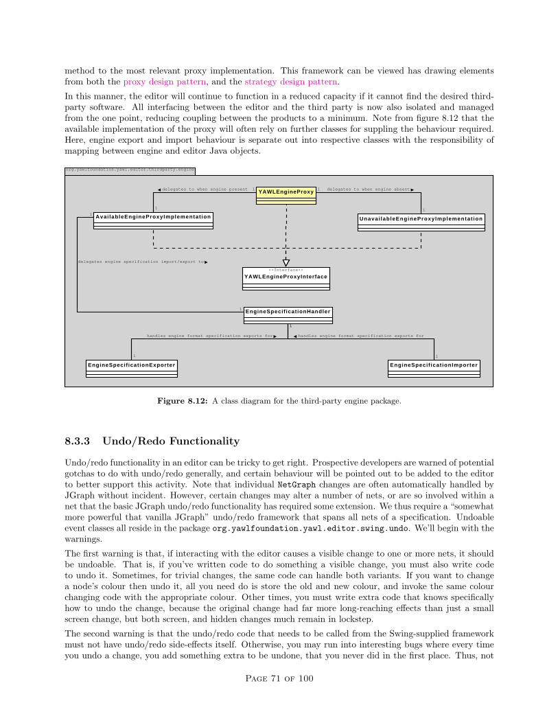
method to the most relevant proxy implementation. This framework can be viewed has drawing elementsfrom both the proxy design pattern, and the strategy design pattern.
In this manner, the editor will continue to function in a reduced capacity if it cannot find the desired third-party software. All interfacing between the editor and the third party is now also isolated and managedfrom the one point, reducing coupling between the products to a minimum. Note from figure 8.12 that theavailable implementation of the proxy will often rely on further classes for suppling the behaviour required.Here, engine export and import behaviour is separate out into respective classes with the responsibility ofmapping between engine and editor Java objects.
org.yawlfoundation.yawl.editor.thirdparty.engine
YAWLEngineProxy
<<Interface>>
YAWLEngineProxyInterface
Avai lableEngineProxyImplementat ion Unavai lableEngineProxyImplementat ion
delegates to when engine present 1
1
delegates to when engine absent1
1
EngineSpecif icationHandler
delegates engine specification import/export to
1
1
EngineSpecificationExporter EngineSpecif icationImporter
handles engine format specification exports for
1
1
handles engine format specification exports for
1
1
Figure 8.12: A class diagram for the third-party engine package.
8.3.3 Undo/Redo Functionality
Undo/redo functionality in an editor can be tricky to get right. Prospective developers are warned of potentialgotchas to do with undo/redo generally, and certain behaviour will be pointed out to be added to the editorto better support this activity. Note that individual NetGraph changes are often automatically handled byJGraph without incident. However, certain changes may alter a number of nets, or are so involved within anet that the basic JGraph undo/redo functionality has required some extension. We thus require a “somewhatmore powerful that vanilla JGraph” undo/redo framework that spans all nets of a specification. Undoableevent classes all reside in the package org.yawlfoundation.yawl.editor.swing.undo. We’ll begin with thewarnings.
The first warning is that, if interacting with the editor causes a visible change to one or more nets, it shouldbe undoable. That is, if you’ve written code to do something a visible change, you must also write codeto undo it. Sometimes, for trivial changes, the same code can handle both variants. If you want to changea node’s colour then undo it, all you need do is store the old and new colour, and invoke the same colourchanging code with the appropriate colour. Other times, you must write extra code that knows specificallyhow to undo the change, because the original change had far more long-reaching effects than just a smallscreen change, but both screen, and hidden changes much remain in lockstep.
The second warning is that the undo/redo code that needs to be called from the Swing-supplied frameworkmust not have undo/redo side-effects itself. Otherwise, you may run into interesting bugs where every timeyou undo a change, you add something extra to be undone, that you never did in the first place. Thus, not
Page 71 of 100

only may you need to write specific code to undo a change, you may also occasionally have to write it in sucha way as to offer two variants, one with undo/redo side-effects, and one without. Listing 8.3 shows an editorclass that requires different code for the undo and redo, that must also be side-effect free.
public class UndoableNetAddition extends AbstractUndoableEdit {
private static final long serialVersionUID = 1L;
private NetGraphModel addedNet;
public UndoableNetAddition(NetGraphModel addedNet) {
this.addedNet = addedNet;
}
public void redo() {
SpecificationModel.getInstance ().addNetNotUndoable(addedNet);
addedNet.getGraph ().getFrame ().setVisible(true);
}
public void undo() {
addedNet.getGraph ().getFrame ().setVisible(false);
SpecificationModel.getInstance ().removeNetNotUndoable(addedNet);
}
}
Listing 8.3: Example undoable editor class
Figure 8.13 is a class diagram, focusing on the undoable edit presented in listing 8.3. It shows how allNetGraph instances pass their undoable events to SpecificationUndoManager, which is capable of applyingchanges across several nets if needs be. It also points points out that SpecificationModel creates a newnet, and passes a specification-level undoable event for its creation to the undo manager. The event codepresented knows to invoke methods on SpecificationModel with no undo/redo side-effects for redoing orundoing the addition of a net to a specification.
org.yawlfoundation.yawl.editor.net
NetGraph
org.yawlfoundation.yawl.editor.specification
Specif icat ionUndoManager manages undo/redo events for1 *
org.yawlfoundation.yawl.editor.swing.undo
UndoableNetAddit ion
Specif icationModel
adds new
1
*
registers specification-wide undo-events with1
1
is registered with1
*
generates and registers
1
*
Figure 8.13: A class diagram undo/redo management of a specification.
The class SpecificationUndoManager has also been enhanced from a typical JGraph undo manager so thatthe programmer can:
• Briefly refuse to record undoable events. This is useful for situations where we wish to make a visiblechange that is controlled by a mechanism other than undo/redo. An example is the toggling of a visible
Page 72 of 100

cancellation set. Whether the set is visible or not is controlled by a popup menu-item for a task, andshould not be reversed or re-applied via typical changes, as there is no “real” change happening to thespecification here, just a visualisation to highlight aspects of existing state.
• Start and stop compounding edits. Sometimes a large change is composed of a number of small changesthat by default, JGraph would make all individual undoable events. Convenience methods are suppliedhere to make it easy to combine a number of edits into a single edit. An example of where this occursis in NetGraph, where re-labeling a task is handled by deleting the old VertexLabel attached to a task,creating a new one, and re-balancing other elements in the task’s VertexContainer as appropriate.
8.3.4 Unit Testing Classes
A small number of JUnit test classes have been written for the editor. Code coverage is currently notsignificant, given the general difficulty with attempting to apply unit-tests to a predominately GUI codebases.What unit tests there are typically lie on the border-regions of the interface between the editor and engine,as this has traditionally been where hard-to-solve compatibility issues have arisen.
The key editor JUnit class is org.yawlfoundation.yawl.editor.TestYAWLEditor.java. This class actsto bootstrap other JUnit classes throughout the editor. Note that a convention for JUnit test classes wasfollowed that the reader should be aware of. A JUnit test class limits its focus to a single editor class. It takesthe name of the class it tests, and prepends the text Test to identify the class it tests. Only JUnit classescan start with Test. A JUnit test class also resides in the same package as the class it tests. As describedearlier, the ant build script ensures that test classes are not shipped with the final editor, and enables a wayof running the JUnit tests outside of an IDE. The build script assumes the above convention in order tocorrectly identify the test classes.
The class TestSpecificationEngineHandler, sitting in thirdparty.engine, is often pivotal to the contin-ued assurance that the engine and editor interact as intended. This class programatically builds a numberof specifications, some valid, some deliberately flawed, and asks the available engine-side code to confirmwhether the specification is flawed or not.
8.4 Future Considerations
This final section of the manual lists a number of issues that have been raised from time to time in the past,but have not yet been satisfactorily addressed, to finally free the editor of its prototype legacy. A commoninhibitor for these items is time. Most of the items listed represent a significant investment in time, and insome cases, with no visible change the the editor’s behaviour to show for the effort.
8.4.1 Engine and Editor Coupling
Currently, coupling between the engine and editor is still higher than preferred. In order to validate aspecification, the editor builds a set of engine objects from the editor model, turns this into engine XML,and asks the engine validation methods to supply feedback on the engine XML. All of these activities relyon calls directly into core engine model objects. This has allowed for early rapid construction of an editorthat can export and validate engine XML, but the necessary cost is a very tight binding between the editormodel and engine model.
The ideal would be to have the editor not rely on engine objects for generating engine XML, but to generateengine compatible XML without the need to call engine library. This would reduce coupling to the engineimmensely, allowing a cleaner separation between the two components than is currently possible.
Page 73 of 100

8.4.2 Data Perspective Complexity
The data perspective of YAWL is complex, and requires deep XMLSchema and XQuery knowledge to suc-cessfully define non-trivial constructs. It is often cited by users as the hardest part of YAWL to understand.The editor currently exposes all of the complexity of the data perspective to users, simply because buildingabstractions to make it easier to wield represents a significant investment in time. Even valid combinationsof scope for passing data from a net to a task and back again is not trivial. The reader is directed toDataVariableSet in org.yawlfoundation.yawl.editor.data for a decision table describing valid scopecombinations.
Approaches put forward for managing data perspective complexity is to either provide better support forthe full complexity of the data perspective through abstractions, or to revisit the data perspective with aview towards simplifying it. For example, converting values as they pass from the net to the task could beremoved, and replaced with a simpler approach where the value passes from net to task unchanged. Anychanges needed on the data needed is then forced to the task level, which is outside the scope of the engine.A simplified data perspective in the engine will result in simplified definition of that perspective in the editor.
8.4.3 Plugin Framework
Since version 1.5 of the editor, a simple plugin framework has been introduced. At the moment this frameworkis primitive, but it has the potential to become a potent extension to the editor. Currently, the pluginframework supports only task icons, and property files that describe extended attributes to be attached totask data variables and decompositions. Ideas for extending the plugin framework include:
• As a mechanism to allow for a library of commonly used decompositions for a particular organisation.
• In a similar vein, to allow a library of common resourcing specifications to be quickly attached toa particular task. For instance, perhaps an organisation typically automatically allocates work toits users via the roles they play in a round-robin fashion, starting the workitem immediately uponallocation. Such a resourcing decision could be pre-generated and available through the organizationsplugin mechanism for quickly attaching to typical tasks in their workflows.
No doubt more behaviour will become candidates for plugin consideration if it represents a typical tighteningof generic behavior to fast-track an organizations typical use of the editor.
Page 74 of 100
Appendix A
Third Party SoftwareAcknowledgements
The YAWL Foundation gratefully acknowledges the use of the following third party software:
1. JGraph(www.jgraph.com)
The YAWL editor makes use of JGraph 5.12.1.1. This version of the JGraph library is covered underan LGPL-style licence and is available separately from: http://www.jgraph.com.
2. Software developed by the JDOM Project (www.jdom.org)
JDOM Beta 9, Copyright ©2000-2003 Jason Hunter & Brett McLaughlin. All rights reserved. Thissoftware is subject to the terms of the licence available at http://www.jdom.org.
3. Software developed by the Apache Software Foundation (www.apache.org)
Xerces2 Java Parser 2.6.0 Release (http://xml.apache.org/xerces2-j/index.html), Copyright ©1999-2003 The Apache Software Foundation. All rights reserved. This software is subject to the terms ofthe licence available at http://xml.apache.org.
Web Services Invocation Framework 2.0 Release (http://ws.apache.org/wsif), Copyright ©1999-2003 The Apache Software Foundation. All rights reserved. This software is subject to the terms ofthe licence available at http://xml.apache.org.
4. The Saxon version 7 XLST Processor from Michael Kay (http://saxon.sourceforge.net). Thissoftware is subject to the Mozilla Public License Version 1.0 and may not be used except in compliancewith that License (a copy is available at www.mozilla.org/MPL). The source code version of this softwareis available under the terms of that license.
5. XSD and EMF (http://www.eclipse.org/xsd, www.eclipse.org/emf) are made available under the Com-mon Public License 1.0, available at www.opensource.org/licenses/cpl1.0.php.
to be completed. . .
75

Page 76 of 100

Appendix B
newYAWL Resource PerspectiveRequirements Analysis
This chapter describes the design requirements for the YAWL 2.0 environment as regards comprehensivesupport for the resource perspective, that were derived from the newYAWL technical report [16], and NickRussell’s PhD thesis [17].
Each of these requirements has been implemented in the YAWL Resource Service and Editor. This analysisis included in this manual for historical reasons, and for consideration of some of the design decisions takenin the development of the Resource Service and relevant extension to the Editor.
B.1 Introduction
There are three key perspectives to workflow. Namely control-flow, data, and resourcing, representing thesequencing in which work needs to be done, the data needed to do work, and the participants needed to dothat work respectively. The three perspectives each provide a view into the same underlying integrated, andultimately inseparable whole of a workflow system.
The newYAWL technical report has identified that the resource perspective is loosely coupled to the control-flow and data perspectives (which themselves are necessarily tightly coupled). Because i) the resource per-spective is so loosely coupled, and ii) the resource perspective is currently the weakest of the three perspec-tives of YAWL, this requirements analysis will be limited in scope to just the proposed resource perspectivechanges described in the newYAWL technical report. Increased support for the other two perspectives willbe considered at some later stage.
Through the preparation of this analysis, it has become clear that the resource perspective changes couldbe handled in a two-phase approach. A number of requirements can be identified as core. They must be inplace initially. The remaining requirements identified need these core requirements to be in place before theythemselves can be implemented. We are therefore capable of building the resource perspective of newYAWLin at least two phases, which will go by the working titles of “core” and “non-core”. Later in this document,the requirements will be allocated one of these two designations.
Note that the newYAWL technical report and its petri-nets capture key concurrency concerns between thesystem, and the participants and administrators. The technical report is to be viewed as the final authorityon the system to be constructed. This document describes the behaviour required in natural language, whichnecessarily results in some loss of accuracy. Readers should view this document as an introduction to easethem into understanding the requirements which are ultimately encoded within the petri-nets of the technicalreport.
77

B.2 Requirements
This section forms the heart of the requirements analysis. To aid in streamlining software construction fromthis document, the requirements have been grouped into subsections, representing major existing componentsof YAWL. Section B.2.1 contains requirements specific to a workflow designer component. Section B.2.2contains requirements specific to a YAWL engine component.
When new requirements are introduced, they take the following generic form comprised of three parts.Firstly, a requirement reference code of the form REQ-###. Secondly, a short text description in italics,and finally, a deeper discussion of the requirement is supplied in the paragraph immediately following. Belowis an example:
REQ-000 : This is an example requirement comprised of a reference code and description
Following each requirement is a detailed discussion of the motivations that go into forming the requirement.
The requirements identified in this document are to ensure that participants interact with the work itemsoffered by YAWL as intended by the newYAWL technical report. The requirements are described in an im-plementation independent manner, allowing differing implementations of YAWL to support the requirementsidentified as best suits each implementation.
Each requirement is classified as either core or non-core. The distinction can be rather arbitrary at times.The guiding heutistic for deciding whether a requirement is core or not is whether the requirement suppliesnecessary support for the concept of interaction points and their ability to be system or user initiated,described later. Non-core requirements can take advantage of this concept but do not necessarilly add to thefundamental behaviour of interaction points. At times, this rule has been broken if it was felt by the authorthat classifying a requirement as non-core would make a system, constructed to only core requirements toolimiting to its users.
B.2.1 Workflow Designer Requirements
In YAWL, atomic tasks and multiple-atomic tasks both represent potential interaction points with workflowparticipants. If these tasks are allocated a “worklist handler decomposition” at design-time, runtime-instancesof these tasks will cause the appropriate worklist handler to offer participants work items where they canreceive work data and check new data back into the workflow system. For atomic tasks, there is one workitem per task instance. For multiple-atomic tasks, there are a number of work items per multiple-atomic taskinstance.
A graphical summary of requirements for a YAWL design tool supporting the newYAWL resource perspectiveis supplied in figure B.1. The requirements are laid out in a hierarchical mind-map. Colour coding is used toisolate a group of requirements that could all belong to the same page of a wizard walk-through type screenthat workflow designers could use to construct a complete resourcing definition for a task. If a group ofone colour exists closer to the root of the tree, requirements from that group will be needed as prerequisitesto requirement groups that appear further out. The requirements listed in figure B.1, along with relateddesign-time requirements are described in further detail next.
REQ-001 : Decompositions are to identify whether they need resourcing.
Decompositions describe how a particular task in a workflow must interact with its external environment.Part of the description is what data should be passed to the external environment and what should bereceived. Interactions with external automated systems to YAWL typically do not allow YAWL to make
Page 78 of 100

Figure B.1: Resourcing Specification in a YAWL DesignerPage 79 of 100

resourcing decisions (such as say, a Web Service invocation). Sometimes, a decision also needs to be made byYAWL on how and when external participants will interact with the work item(s) of a task. Decompositionstherefore need to indicate whether they need resourcing decisions made at workflow design time.
There should always be a default work-list handler decomposition offered by YAWL that is identified asneeding resourcing. All decompositions identifying automated external interaction will not need resourcingdecisions. All decompositions identifying manual external interaction will need resourcing decisions.
This requirement is classified as core.
REQ-002 : Atomic and Multiple-Atomic Tasks with “resourcing required” decompositions will be allowed tospecify necessary resourcing requirements.
For tasks with decompositions needing resourcing, workflow designers will be able to specify resourcingrequirements for those tasks at design time. Note that a number of tasks can share the same decomposition.Each task will require resourcing decisions to be made, but each task may have a different resourcing choicemade. The actual resourcing decision made by the designer will thus be per task, not per decomposition.
As the resourcing decision belongs to a particular task, that decision remains fixed across all work item(s)of a multiple-atomic task, and across all work items of a task that is within a loop. It will not be possibleto specify resourcing per sub-instance of a multiple-atomic task, or for each particular iteration of an atomictask work item. However, as the resourcing decision must be re-evaluated upon each work item instantiationat runtime, it will be possible for the resourcing decision to result in a number of work items for a singlemultiple-atomic task to be spread across a number of participants, for example.
At a high level, the workflow designer needs to be able to describe whether either users or the system isresponsible for resourcing at key interaction points. They will also need to occasionally dictate what runtimeprivileges a user will be granted for a task. At design time, a task with resourcing required will inherit a“global” resourcing decision default that the designer must override where appropriate.
This requirement is classified as core.
REQ-003 : For tasks requiring resourcing, workflow designers will be able to specify either system or userinitiated behaviour for each of its Offer, Allocation, and Start interaction points.
Three interaction points have been identified for where participants and the workflow system can makework-distribution choices. They are listed below in order of execution:
Offer: A work item can be offered to a participant. This does not imply that the participant should undertakethat work, merely that they could. A number of participants could be offered the same piece of work,for example.
Allocation: Allocating a work item to a participant means that participant has been committed (willinglyor not) to doing that work item some time in the future. This participant no longer could do the work,but rather should do it. The work item is withdrawn from the offered queues of other participants.
Start: A work item goes from allocated to started once work has begun. The participant that once shouldhave been doing the work has now started doing so.
For relevant tasks, workflow designers will be able to specify how each interaction point should be handledin a running workflow by choosing whether that interaction point will be system initiated or user initiated.System-initiated offers and allocations require further decisions to be made by the workflow designer to guidethe running workflow system in its choices.
This requirement is classified as core.
REQ-004 : For tasks requiring resourcing, a workflow designer must be able grant or deny a number of
Page 80 of 100
user-task privileges for the task’s work item(s).
A workflow designer will be supplied a number of user-task runtime-privileges, that can be either enabled ordisabled for the resourcing-required task. These privileges are so-named because they will only be enabledfor a (user, task) combination. The privileges, and their runtime effect when enabled are described below:
Can Suspend: When enabled, participants who’ve started work items of the task will be allowed to suspendthe execution of the task.
Can Reallocate Stateless: When enabled, participants who’ve started work items of the task will beallowed to reallocate the work items to other users. The process of re-allocation will revert the workitem to an initial starting state.
Can Reallocate Stateful: When enabled, participants who’ve started work items of the task will be allowedto reallocate those work items to other users. The process or re-allocation will preserve the currentstate of the work item.
Can Deallocate: When enabled, participants allocated work items of the task will be allowed to de-allocatethemselves from the work items, causing a reallocation of the work item.
Can Delegate: When enabled, participants allocated work items of the task will be allowed to reallocatethe work items to other users, so long as they have not yet been started.
Can Skip: When enabled, participants allocated work items of the task will be allowed to skip (or finishwithout starting) the work item. Therefore, this privilege will only be grantable on tasks that supplydefault values for all of their output parameters.
Can Pile: When enabled, a participant will be allowed to pile the execution of all work items of this taskupon themselves. Instead of the workflow system building a distribution set of viable participantsfirst, it will directly allocate and automatically start new work items for the task against the relevantparticipant.
To avoid a combinatorial explosion within a running engine in relation to setting individual permissionsagainst combinations of users and tasks, we also need a switch per enabled-privilege. The switch will indicatewhether all users that are allocated the task are granted the privilege by default or not. An administratorwill still be free to override the default, but we expect the default to cover the desired behaviour of mostusers involved in the given workflow.
The priviliges discussed above can be viewed as non-core. Administrative functions described later will becapable of the short-circuiting of work items through to alternate worklist states, which can act as a work-around until such time as non-core requirements can be constructed for many of the privileges here. This willplace extra burden on aadministrators until such the non-core requirements are constructed. Those privilegesthat have no administrative fall-back behaviour do not contribute to supporting interaction point behaviour,but will result in the loss of some pattern support.
REQ-005 : To support the Can Skip user-task privilege, tasks will be able to specify default values for theiroutput parameters.
The workflow designer will be allowed to specify an optional static value for any of its output parameters.If the designer chooses optional, they will also be asked by the design tool to supply a static “default” valuefor the optional parameter. This optional value will be used to create “completed” data when the work itemis automatically completed upon a user-request to skip that work item. Note that all of a task’s outputparameters must have optional values specified in order for it to be validly skipped at runtime.
Page 81 of 100

This requirement is classified as non-core.
REQ-006 : For tasks requiring resourcing, a default decision of user offer, user allocation, user start,will apply for a task’s interaction points. No privileges will be granted by default.
All tasks that require resourcing need a default resourcing decision that a task inherits initially, and thata workflow designer can choose to override as necessary. Defaulting is required for interaction points andruntime privileges.
For the three interaction points described earlier, the default will be user for each interaction point. Thiswill result in all decisions on resourcing to be manually handled at runtime within a YAWL engine. For theuser-task privileges, all privileges will default to being disabled, giving users minimal freedom in their abilityto manipulate work items of the task at runtime.
This requirement is classified as core.
REQ-007 : Workflow designer to specify how a System-Initiated Offer will choose participants.
When the workflow designer identifies that offers should be system-initiated (regardless of what choicesthey make for the allocation and starting points), the workflow designer will also be required to specify adistribution strategy for the offer, with ultimately tells the running workflow system how to generate a listof participants to which a work item should be offered.
Initially this will involve having the design tool ask the workflow designer to specifying a number of taskrouting strategies, and optionally, to specify whether the workflow system will retain a “familiar participant”for allocating a work item to. Both options are described in a number of requirements that follow.
This requirement is classified as core.
REQ-008 : Workflow Designer to be able to specify task routing strategies for a resourcing-required task
When a workflow designer has chosen to specify task routing strategies after having specified that offers are tobe system-initiated, the design tool will require the following sequence of steps to be followed by the workflowdesigner:
1. Specification of a base distribution set,
2. Specification of filters for the base distribution set using organisation, capability and historical data,
3. Specification of a number of runtime constraints for this filtered distribution set.
Each step is further described in requirements that follow.
This requirement is classified as core.
REQ-009 : Workflow Designer to be able to specify a base distribution set of participants.
A workflow designer begins building a task routing strategy by defining a base distribution set of participants.The designer will be able to do this by selecting participants through a number of mechanisms. The set ofparticipants represented by these selections will be used at runtime to generate a base distribution set ofparticipants to whom work items of the relevant task will be offered. The three mechanisms defined foradding participants to this base distribution set are:
• choose zero or more of the participants registered as users to the workflow system,
• choose zero or more of the roles defined by the workflow system,
Page 82 of 100

• choose zero or more of the input parameters to the relevant task, and specify for each of these parameterswhether the value of the parameter will contain a set of participants, or a set of roles at runtime.
This requirement needs the workflow designer and engine to communicate, where the engine supplies a fullset of participants, and a full set of roles to the workflow designer. For reasons more fully in the followingrequirement, the identification of roles and participants must be done in a data storage independent mannerto allow a range of technologies to pass resourcing data between the workflow engine and the design tool.
This requirement is classified as core.
REQ-010 : Workflow Designer to be able to specify filters for a base distribution set of participants usingorganisation, capability and historical data.
Once a workflow designer has defined a base distribution set of participants, they can then specify a numberof filters that are to apply to the participant set. Three different categories of filter have been defined below:
• Organisation Filter
• Capability Filter
• History Filter
At runtime, all categories of filter will have access to the base distribution set of participants, plus any extradata relevant to their category (detail of which is described in the newYAWL technical report). Regardlessof category, the filters constructed will generate a subset of the base distribution set of participants. Onlythose participants of the base distribution set that are valid members within all of the filters chosen will beincluded within the filtered distribution set of participants.
The workflow designer will be offered all filters registered with a running YAWL engine. They may thenchoose to enable a number of these filters, and supply data for whatever parameters each filter requires toenact its algorithm at runtime within the engine.
This requirement needs the design tool and engine to communicate, where the engine supplies a the designtool the full set of filters and necessary parameters. It also requires the engine specification to be flexibleenough to identify a filter and the parameters values for it. Filters are to be built as plugins into a runningengine, and cannot thus be hard-coded into a workflow specification.
Initially, one filter per category will be constructed to offer a “typical” simple filter for a category. Thesefilters will be backed by a relational database that the filters will query. However, We expect alternate filtersmay need to draw their resourcing data from alternate technologies to relational databases. LDAP serversare often quoted as a typical example.
Note that the backing technology used to house the data needed for these filters will also be the sametechnology that stores participants and roles. The engine processing that reports participant and role liststo the workflow designer should allow for alternate technologies to relational databases to supply this data,but will be released initially with participants and roles being stored within a default relational databasethat comes with the engine. It is expected that a particular data storage technology will require its ownresourcing plugin to a YAWL engine, and at the very least must offer the ability to retrieve all participantsand rolls registered within its data storage technology.
An alternative to the above approach would be to construct a language, catering a large range of possiblefiltering strategies. The design and implementation of such a language with no clear understanding typicalor desired filters is considered to be a poor investment of programming effort at this stage.
This requirement is classified as non-core. A rudimentary degree of filtering can be achieved by allocatingparticipants to rolls that encode simple organisation or capability detail. It should be noted, however thatfull pattern support for organisation, capability and history based patterns cannot be claimed until thisrequirement is implemented.
REQ-011 : Workflow Designer to be able to specify of a number of runtime constraints for this filtered
Page 83 of 100

distribution set.
A workflow designer needs to be able to define two runtime constraints for a filtered distribution set. Oneconstraint, separation of duties must be enforced on a filtered base distribution set of participants. The other,piled execution, allows the filtered distribution set to be ignored under certain circumstances at runtime. Bothruntime constraints are boolean. However, separation of duties also requires a “familiar task” to be chosenwhenever it is active. The constraints, and the effect they may exhibit at runtime, are described below:
Retain Familiar: When this constraint is enabled, it must also have a “familiar task” chosen to be comparedagainst. This constraint attempts to ensure that at run-time, the last participant that completed a workitem of this familiar task within the same process instance will be also allocated work items spawnedoff the relevant resource-requiring task.
Separation of Duties: When this constraint is enabled, it must also have a “familiar task” chosen tobe compared against. This constraint ensures that the filtered distribution set will not include anyparticipant who completed work item(s) of the “familiar task” in the current case.
Piled Execution: Enabling this constraint will allow a participant to choose at runtime for the task, toreceive all work items for the task across all cases of the workflow specification, thereby overriding thedistribution set of participants specified for that task. Note that at run-time only one user can be pilingthe execution of a task’s work items at any one time.
For the retain familiar constraint, The relevant “familiar participant work item” must also have completedbefore the resourcing required work item for this runtime constraint to be enacted. Thus, only resourcing-required tasks within the that lie on a backward path to the starting net’s input condition from the resource-requiring task will be selectable as the familiar participant task at design time. This rule also holds forseparation of duties familiar tasks.
For the constraints requireing familiar tasks, note that concurrency could still result in the specified familiartask not having a completed work item being ready for determining the farmiliar participant. In suchcircumstances, the engine should fall back to typical behaviour where it generates a distribution set ofparticipants to offer the work-item to.
The separation of duties and retain familiar constraints are to be considered core. The piled execution isto be considered non-core. Piled execution is an alternative to the interaction point behaviour described todate. It’s exclusion will deny pattern support, but it can be added into a system once the base interactionpoint behaviour has been established.
REQ-012 : Workflow designer to choose System-Initiated Allocation mechanism.
If the set of participants offered a work item contains only a single participant, the running workflow systemdoes not need to choose between alternatives, and may allocate the work item directly when system-initiatedallocation is being used. However, no guarantee can be made at design-time that an offer will be limited to asingle participant at runtime. A design-time choice needs to be made to tell the YAWL system how it mustchoose a single participant from a number of possible alternatives for allocation. Ultimately, so long as analgorithm takes a participant set, and returns only one of those participants, it could be considered a validautomated allocation mechanism.
Initially, three mechanisms will be constructed. A workflow designer may chose from these three mechanisms:
Round-Robin: From the identified participants, choose the one who recently completed a work item forthe task. In the event that several users are recorded as being equally least-recent, choose one of theserandomly.
Shortest-Queue: From the identified participants, choose the one whose sum of allocated and started workitem queue numbers is shortest. This will be used as the default choice.
Page 84 of 100
Random: Choose a participant from the collection identified randomly.
The mechanisms will be registered with the workflow engine and communicated to the workflow designerwhen they come to choose an appropriate mechanism for system-initiated allocation. As new mechanismsare programmed and registered with a running engine, they will be subsequently made available to theworkflow designer to choose from as well.
This requirement will need a workflow specification passed from the workflow designer to a newYAWL engineto be sufficiently flexible to allow new mechanisms to be identified within the workflow specification withoutrequiring changes to the specification structure.
This requirement is classified as core.
REQ-013 : Resourcing Decisions made must be encoded within the task definition of a YAWL specification.
The specification generated by a workflow design tool for consumption by a newYAWL resourcing-enabledsystem must encode the resourcing-required choices made by a workflow designer that have been describedin this section. The requirements listed below require special effort to ensure that as new options are madeavailable by an engine for key decisions, the specification does not require structural changes in order to havethem identified:
• Workflow Designer to be able to specify filters for a base distribution set of participants using organi-sation, capability and historical data.
• Workflow designer to choose System-Initiated Allocation mechanism.
This requirement is classified as core only so-far as is encodes other core requirements described to date forenactment within a newYAWL resourcing-enabled system.
B.2.2 Workflow System Requirements
One of the quintessential elements of a YAWL workflow is the work item, representing a piece of workthat an external participant must do in order to progress a workflow. It is through a work item that anexternal participant and the workflow system must interact. Work items are offered to a participant viathe participant’s view into a worklist handler component. Besides the many and varied ways of classifyingusers of a newYAWL system that have been identified earlier, users can also act as administrators to YAWL.Administrators have an extra responsibility of manually coordinating the placement of work with participantswhere appropriate.
We therefore have two basic workflow system roles that users may play in newYAWL, participants andadministrators. A workflow system role is not to be confused with organisation roles described earlier. Whatrole(s) a user plays within an organisation matters only so far as they can be used by the workflow systemto short-list possible participants that may do a work item. Anybody who does work through YAWL playsthe workflow system role of participant, regardless of how they are shortlisted for being offered work itemsto, be that through an organisational role, or some other mechanism.
Figure B.2 is a mind-map showing a hierarchical view of screens that must be supported to allow bothadministrators and participants to interact with YAWL in order to support the resource perspective changesof the newYAWL technical report. The requirements that describe user interfacing have also been markedwhere appropriate.
This section is broken into three sub-sections. Section B.2.2 describes requirements for YAWL workflowadministrators. Section B.2.2 describes requirements for participants doing non-administration duties viathe worklist handler. Finally, section B.2.2 describes automated requirements that are independent of thosedescribed in the previous sections.
Page 85 of 100

Figure B.2: A Screen Hierarchy of Resourcing support for a newYAWL System
Administration Requirements
This section describes requirements for user interfacing that administrators will need to support the resourceperspective of newYAWL.
REQ-014 : YAWL Administrator to be able to manage user privileges
YAWL administrators will be supplied functionality to select a number of workflow participants and changetheir user privileges. The default setting for all privileges is to be disabled. The following privileges, whenenabled for a participant, will apply across all cases that the participant can be involved in:
Can Choose Work Item to Start: When enabled, this privilege allows a participant to choose whichwork item in their allocated queue they will be allowed to start. When this privilege is disabled, theparticipant will not be able to select which work item to start. Instead, the work item at the top of theallocated queue of the participant will be started when the participant triggers a start action.
Can Start Concurrent Work Items: When enabled, this privilege allows the participant to place newwork items in their started queue before they complete existing work items. Note that this does notstop an administrator or the system from placing extra work items on a user’s started queue when theyalready have started work items. When disabled, a participant will only be able to add a work item totheir started queue when the queue is empty.
Can Reorder Work Items: When enabled, this privilege allows the participant to reorder the work itemsin their allocated queue. When disabled, the work items will be added to the end of the queue, meaningthat the longer a work item has remained in the allocated queue, the higher to the top of the queue itwill be.
Can View All Offered Work Items: When enabled, this privilege allows the participant to view theoffered queues of all other workflow participants.
Can View All Allocated Work Items: When enabled, this privilege allows the participant to view theallocated queues of all other workflow participants.
Can View All Executing Work Items: When enabled, this privilege allows the participant to view thestarted and suspended queues of all other workflow participants.
Page 86 of 100

Can Chain Work Item Execution: When enabled, this privilege allows the participant chain a numberwork items together so that so that a new task in the sequence of work will be allocated to them andautomatically started.
There is some argument that all of the above user privileges should be viewed as non-core, given that theyare all dependent on the concept of interaction point behaviour, but do not add to that behaviour. However,the top three privileges are viewed by the author as being highly desirable ways of toggling a particularparticipant’s way of working that we could reasonably expect to be desired by workflow systems. Therefore,the top three requirements are to be considered core, and the remaining “view all” privileges as non-core.
REQ-015 : YAWL Administrator to be able to override default user-task privileges
User-task privileges are initially configured through settings supplied in the workflow specification as describedby a workflow designer. However, an administrator may be required to vary user-task privileges away fromthe defaults set in the workflow specification.
Administrators will be supplied a user-task privilege maintenance screen. The aid in navigating a largenumber of possible tasks, A tree hierarchy of specifications will be supplied. Each specification lodged withthe workflow system will be listed and will be openable to reveal individual nets. Each of these nets can befurther opened to show all tasks within that net that have resourcing requirements. These tasks can then befurther opened to show each user-task privilege, along with the default setting for the privilege. The privilegecan then be further opened to reveal a list of participants that explicitly go against the default setting. Theadministrator will then be allowed to add or remove users from this list as necessary.
This requirement is classified as non-core.
REQ-016 : YAWL Administrator to be allowed management intervention via an Unoffered queue and aWorklisted queue
YAWL Administrators will require a management intervention screen for managing work items in variousstates of their lifecycle. From the perspective of a YAWL Administrator, work items are either Unoffered,or they are one of the worklist states described later (Offered, Allocated, Started or Suspended). Giventhe fundamentally different nature of the actions that can be performed between unoffered work items andthose that have begun appearing on the worklists of participants, the management intervention screen willseparate work items into two separate queues. One queue will contain all Unoffered work items. The otherwill contain the remaining worklisted work items.
The actions that can be applied to both queues are described in the succeeding requirements. The petri-netfor management intervention is figure 33 of the newYAWL technical report.
This requirement is classified as core.
REQ-017 : YAWL Administrator to be able to enact administrator-initiated offers, allocations and startingof Unoffered work items in the management intervention screen
Those work items whose resource-requirements indicate user-initiated offers, or that have failed to be success-fully distributed to a set of participants will appear on the Administrator management intervention screenwith a status of Unallocated. The administrator must be able to select a number of these work items andfor them, specify a number of participants. Once the participants have been identified, the administratorwill be able to enact one of three possible actions on the work item selected:
Offer: Selecting this action will result in the relevant work item being offered to the selected users. In thismanner, user-initiated offers are implemented.
Allocate: This action will only be possible when a single participant has been selected. Enacting this actionwill directly allocate all selected work items to the chosen participant.
Page 87 of 100
Start: This action will only be possible when a single participant has been selected. Enacting this actionwill directly allocate all selected work items to the participant and automatically place the work itemson the participant’s started queue.
This requirement is classified as core.
REQ-018 : YAWL Administrator to be able to escalate worklisted work items from the management inter-ventions screen
The worklisted queue of the management intervention screen will display, by default, all work items that areoffered, allocated, started and suspended. To ease the administrative burden of locating desired work itemsfrom a potentially very large list, the administrator’s screen will initially display all work items currentlyworklisted, along with whoever has been assigned the work item, and the work item’s current state. They maythen choose to filter the work items on a per-participant basis, and a per-status basis. When an administratorchooses both a participant, and a status, the filter will show only those work items of the required state thathave been assigned to to the selected participant.
From the queue, the administrator will be able to escalated a number of selected work items to a potentiallydifferent set of participants. They will be able to select a number of work items, as well as a number ofparticipants that they may then enact one of the following actions upon:
Escalate Offered, Allocated, Started or Suspended to Offered: All selected work items will be with-drawn from the offered, allocated started and suspended queues that they were initially assigned to.The work items will then be added to the offered queues of the newly selected participants. Startedand suspended work items will have their state reset to an initial state.
Escalate Allocated, Started or Suspended to Allocated: This action will only be possible when a sin-gle participant has been selected. All selected work items will be withdrawn from the worklists of theparticipant to whom the work items were assigned. The work items will then be added to the allocatedqueue of the new participant. Started and suspended work items will have their state reset to an initialstate.
Escalate Started to Started: This action will only be possible when a single participant has been selected.All selected work items will be withdrawn from the started or suspended queues of the participantsto whom the work item was assigned. The work items will then be added to the started queue of theselected participant, preserving state in the transfer. Not currently in report.
This requirement is classified as core.
Work List Handler Requirements
A participant’s worklist handler is their interface into the various work items that they must interact within order to contribute to the execution of an overall workflow instance, or case. Where a work item sitswithin the worklist of participants depends ultimately on the state of the work item. Figure B.3 is a UMLStatechart of the lifecycle of the newYAWL work item. Figure B.4 informally describes each state thatappears in figure B.3. Note that the state chart does not cover all possible state transitions. It’s primaryfocus is to describe how the work item changes from the perspective of workflow participants.
Transitions between states in figure B.3 take a general form of “number. transition name”, referring thefigure number in the newYAWL technical report and the actual petri-net transition within that figure thatcauses a work item state change. One thing that immediately becomes obvious is that a work item can onlygo through a small number of possible states in its lifecycle, but there are many possible valid transitionsbetween those states.
Page 88 of 100

Fa
iled
[distributionSize==0]/
36. process distribution failures
[!(chained|piled|auto) and OIP=System]/
35. route work items to users
[distributionSize>0,OIP=System,AIP=User]/
37. route offers
[distributionSize>0,OIP=System,AIP=System,SIP=User]/
38. route allocation
Offe
red
Allo
ca
ted
Sta
rted
[distributionSize>0,OIP=System,AIP=System,SIP=System]/
39. route work item for immediate start
[!(chained|piled|auto) and OIP=User]/
40. manual-distribution
Dis
tribu
ted
48. start
46. process selection request
Su
sp
en
de
d
49. suspend
49. resume
50. complete
53. process stateful reallocation
53. process stateless reallocation
[distributionSize>0,OIP=User,AIP=User]/
41. process manual offers
[auto]/
45. complete autonomous work item
[auto]/
44. initiate autonomous work item
[distributionSize>0,OIP=User,AIP=System,SIP=User]/
42. process manual allocations
[distributionSize>0,OIP=User,AIP=System,SIP=System]/
43. process manual immediate start
52. process deallocation51. route delegation
55. process reallocation
54. process reoffers
[chained|piled]/
35. route work items to users
OIP = Offer Interaction Point
AIP = Allocation Interaction Point
SIP = System Interaction Point
* How to move from failed to other states?
* Need a discussion on canceled work-items
and what that means to work-item state.
Stopped as a new state?
Pa
rticip
an
t trigg
ere
d tra
ns
ition
Ad
min
istra
tor trig
ge
red
tran
sitio
n
Sy
ste
m trig
ge
red
tran
sitio
n
40. manual-distribution
Todo:
34. interrupt handling
33. Escalation
72. Forced Cancel
73. Forced Complete
74. Forced Fail
[distributionSize>0,OIP=System,AIP=System,SIP=System, not concurrent and #Started > 0]/
39. route work item for immediate start
Figure B.3: Work-Item State Chart
Page 89 of 100

State DescriptionInitial state The work item exists, but has not yet had a possible set of participants identified
to be distributed to.Distributed A distribution set of possible workers exists for the work item.Offered The distribution set of possible participants have been offered the work item to
do.Allocated One of the possible participants that could do the work item’s work has been
allocated the work to do.Started A participant, previously allocated a work item, has begun its work.Suspended A participant has suspended a work item they started earlier.Final state The work item is complete.
Figure B.4: State for the Work-Item State Chart
The requirements in this section spell out how a work list handler for newYAWL must interact with partici-pants in managing work items that participants may work on.
REQ-019 : Participants are to have login and preferences screens that support specifying chained and piledexecution
Upon login, participants will be offered a typical username and password interface. At this time, participantswill also be able to toggle whether they wish to pile execution for those tasks have they have been grantedthe Can Pile privilege. Only one logged-in participant may pile the execution of a task’s work items. Onlythose tasks that do not have a logged-in participant piling their work items will be offered to the participantfor toggling the piling of. The default for the toggle shall be to not pile execution.
If the participant has also been granted the Can Chain Work Item Execution privilege by an adminis-trator, the login screen will also allow the participant to toggle whether they wish to chain execution of workitems. The default for the toggle shall be to not chain execution.
A preferences screen should also be provided to the logged in user, allowing them at any stage whilst theyare looged in to toggle these execution mode preferences.
The petri-net for participant login is figure 71 of the newYAWL technical report.
A participan login screen is considered core. However, this requirement is classified as non-core in thatchaining and piling are not core requirements.
REQ-020 : Participants are to be offered separate queues on their work list handler for work items that arewithin the states of Offered, Allocated and Started.
Looking at figure B.3, we see that typical workflow participants can only interact with work items whenthe work items are in the states of Offered, Allocated, Started and Suspended. Collectively, we label thesestates the worklist states, indicating that whilst within one of these states, participants may interact witha work item in certain ways. Each of these states dictate a limited number of valid interactions that theparticipant may perform whilst a work item is in a particular state. Interactions per state are described inlater requirements.
Participants will be offered a worklist handler interface that clearly separates work items into their respectivestates. For screen real-estate concerns, it does not seem necessary for all queues to be visible to the participantsimultaneously. A tabbed interface may be most appropriate. However, a special case may be that of theStarted and Suspended queues. There is some interface pressure for these two queues to appear on the samescreen. It is expected that the state of both the started and suspended work item queues for a user willinfluence which suspended work they should resume once the participant completes a work item.
A word of warning is offered here on web-based interfaces supporting this requirement. Web-techologiesassume a client-pull model (the participant asks the sever for work updates with an explicit screen refressh
Page 90 of 100

action made by the participant). It is possible to construct a server-push interaction where the workflowsystem pushes new or updated work items out to a participant’s web browser, but this requires the use ofAJAX technologies, which are a immature at the time of writing this document, and likely to consume asignificant amount of effort to get working across the most popular Web browsers. Client-pull will involveless programming effort, but will not be as user-friendly as server-push.
This requirement is classified as core.
REQ-021 : Workflow Participant to be able to enact self-allocation from their Offered queue, as well asview all offered work items when appropriate.
For those work items whose resourcing requirements indicate user-initiated allocation, the participant musthave a mechanism for self-allocating work items that appear in their offered work item queue. The participantwill be able to select a number of the work items on this queue and enact an allocate action upon them.
For each of the work items that the participant allocates in this manner, if a work item is also user-initiatedstart, the action will move the work item from their offered queue to their allocated queue and withdraw thework item from the offered queues of other participants. If the work item is instead flagged for system-initiatedstart, the action will move the work item from the participant’s offered queue directly to their started queueand withdraw the work item from the offered queues of other participants.
The petri-net requirement for doing this user-initiated allocation is described in the process selection requesttransition in figure 46 of the newYAWL technical report.
If the participant has the Can View All Offered Work Items privilege set, the participant will also besupplied a toggling mechanism, allowing them to view (but not otherwise manipulate) all other offered workitems in the entire system. So as not to interfere with their own offered work items, these other offered workitems will appear in a visually distinct queue on the same screen as the participant’s own offered work items.An indicative screenshot of this requirement is supplied in figure B.5.
This requirement is classified as core. However, the ability to view all other work items of the same state isnon-core.
REQ-022 : Workflow Participant to be able to enact self-start, delegation, self-deallocation and toggle viewingall work items from the Allocated queue when appropriate.
For those work items whose resource-requirements indicate user-initiated start, the participant will havea number of allocated work items available to start. A start action will be made available to allow theparticipant to move a work item from their allocated queue to their started queue.
Unless the user privilege Can Start Concurrent Work Items is enabled for a participant, they will notbe able to activate the start action until their started work item queue is empty. If the user privilege CanChoose Work Item to Start is enabled, the participant will first need to select a work item to enact thestart action upon. When this privilege is disabled, the top-most allocated work item will be started. Thepetri-net requirement for doing this user-initiated start is captured in the start transition in figure 48 of thenewYAWL technical report.
With certain privileges enabled, participants may also be able select a work item from their allocated queueand enact one of the following actions:
Delegate to another: If the combination of participant and work item has the Can Delegate privilegeenabled, the participant may chose some other participant to delegate the work item to. The effect ofthis will be to move a work item from the allocated queue of this participant to the allocated queue ofthe delegate. Note that only those participants that may be validly offered this work item (i.e., thoselisted in the distribution set of the work item’m task) will be offered as possible delegates. The petri-nettransition for this is named route delegation in figure 51 of the newYAWL technical report.
Deallocate themselves: If the combination of participant and work item has the Can Deallocate privilegeenabled, the participant may chose to deallocate themselves from the work item. The effect of this will
Page 91 of 100

Figure B.5: A possible offered queue implementation interface
be to remove the work item from this queue, and place it on the unallocated queue of the administratormanagement intervention screen discussed earlier. The petri-net transition for this is process deallocationin figure 52 of the newYAWL technical report.
Reorder work item: If the participant has the Can Reorder Work Items privilege set, the participantwill be allowed to select a work item in the allocated queue and move that work item up or down intheir work queue. Work items closer to the top of the queue are expected to be started before workitems further down in the queue, which is especially true when the Can Choose Work Item to Startprivilege is disabled for the combination of participant and work item.
Skip a work item: if the combination of participant and work item has the Can Skip runtime privilegeenabled, they will be allowed to select a work item from the allocated queue and skip it, automaticallycompleting that work item, using default values of data that the work item must output to subsequentwork in the case.
Toggle view all work items: If the participant has the Can View All Allocated Work Items privilegeset, the participant will be supplied a toggling mechanism, allowing them to view (but not otherwisemanipulate) all other allocated work items in the entire system. So as not to interfere with their ownallocated work items, these other allocated work items will appear in a visually distinct queue on thesame screen as the participant’s own allocated work items.
An indicative screenshot of this requirement is supplied in figure B.6.
This requirement is classified as core. However, most of the actions listed that are driven off privileges are
Page 92 of 100

Figure B.6: A possible allocated queue implementation interface
to be considered non-core, except Reorder work item which is core.
REQ-023 : Workflow Participant to be able to enact stateful reallocation, stateless reallocation, suspension,completion and viewing all started work items from the Started queue.
Participants will be able to select a work item from their started queue, and apply one of the following actions(some of which may only be made available when appropriate privileges are granted):
Stateful Reallocation: If the combination of participant and work item has the Can Reallocate Statefulprivilege enabled, the participant may chose some other participant to reallocate the work item to. Theeffect of this will be to move a work item, in its current state, to the started queue of the selectedparticipant. The petri-net transition for this is named process stateful reallocation in figure 53 of thenewYAWL technical report.
Stateless Reallocation: If the combination of participant and work item has the Can Reallocate State-less privilege enabled, the participant may choose some other participant to reallocate the work itemto. The effect of this will be to reset a work item to its initial state, and move it to the started queueof the selected participant. The petri-net transition for this is named process stateless reallocation infigure 53 of the newYAWL technical report.
Suspend: If the combination of participant and work item has the Can Suspend privilege enabled, theparticipant may choose to suspend the work item. The effect of this will be to move the work itemfrom the started queue to the suspended queue of the participant. The petri-net transition for this isnamed suspend in figure 49 of the newYAWL technical report.
Page 93 of 100

Complete: When a participant chooses to complete a work item, it will be removed from the started queueof the participant, and its state used to complete the work item, progressing the overall workflow asdictated by the specification of the workflow. The petri-net transition for this is named complete infigure 50 of the newYAWL technical report.
Toggle view all work items: If the participant has the Can View All Executing Work Items privilegeset, the participant will be supplied a toggling mechanism, allowing them to view (but not otherwisemanipulate) all other started and suspended work items in the entire system. So as not to interferewith their own started and suspended work items, these other work items will appear in a visuallydistinct queue on the same screen as the participant’s own started and suspended work items.
Participants will also be able to open a number of their started work items and work on (edit) their stateindividually. The actions described above will also be made available to the participant whenever they areworking with an individual work item. When the suspend action is chosen, the individual work item screenwill become read-only and will only behave as described below.
An indicative screenshot of this requirement is supplied in figure B.7.
Figure B.7: A possible Started queue implementation interface
This requirement is classified as core. The actions listed above except Suspend andComplete are to beconsidered non-core.
REQ-024 : Workflow Participant to be able to enact work item resumption from the Suspended queue.
Participants will be able to select a a work item from their suspended queue, and apply a resume actionto that work item. If the participant does not have their Can Start Concurrent Work Items privilege
Page 94 of 100
enabled, they may not resume the work item until their started queue is empty. The effect of applyingthe resume action will be to to move the work item from the suspended queue to the started queue of theparticipant. The petri-net transition for this is named resume in figure 49 of the newYAWL technical report.
Participants will also be able open a number of the suspended work items to view individually in a read-onlycapacity. The resume action will also be made available to the participant as they view the work item.Choosing the resume action from this individual work item screen will also activate relevant actions that canbe applied to work items in the started queue. Of course, this will also have the effect of the participant nolonger being able to resume the work item without suspending it again first.
This requirement is classified as core.
Automated Workflow Requirements
This section describes the automated requirements of a resource perspective for YAWL that matches thenewYAWL technical report.
REQ-025 : System to support automatically piling work items for a particular task to the relevant participant
Work items for a particular task can be piled onto a single participant, meaning that all work items spawnedfor a task across all running cases of a workflow specification of that task will be directly allocated to andautomatically started for a single logged-in workflow participant. A number of pre-requisites must existbefore the system can pile work items to the participant in this manner:
• Design-time enablement of the Can Pile privilege for the participant and task.
• A logged in participant who has indicated that they wish to pile all work items for the selected taskto themselves, disallowing any other participant from piling work items of the selected task until theyeither log off, or indicate that they no longer wish to pile work for the task whilst still being logged in.
• Run-time enablement of the Can Pile either through design-time defaulting of enablement for therelevant participant or through explicit enablement by an administrator.
If it is possible for the work item distribution component to pile a work item, it will do so, before it attemptsto chain work items, and before it attempts to follow resourcing directives on offering or allocating the workitem described at design time. Note that a user logging out will ensure that work will stop being piled tothem.
This requirement is classified as non-core.
Check models for what happens when the participant logs out as the piling is being evaluated.
REQ-026 : System to support automatically chaining work items to a relevant participant
For a participant to chain work items, they must have the privilege Can Chain Work Item Executionenabled, and have signaled at logon that they wish to chain the execution of work items. The chaining ofwork items is the subsequent automatic allocation and starting of work items once the participant finishessome work item. The work item distribution component will need to evaluate the distribution set of possibleparticipants it could have offered new work items to. Should the chaining enabled participant appear in thisdistribution set, they will be automatically allocated and triggered as having started the new work item. Ifchaining is not possible for the participant, the work distribution component will default back to offering anew work item to participants in this distribution set.
Note that there is the potential for some subtle unintended side effects in the control flow perspective witha very free applicability of chaining. For example, were we to allow deferred choice through a conditionthrough to two subsequent tasks, one of which does not included the chaining participant, but other does,we have effectively short-circuited workflow, stopping the deferred choice from occurring. Other problems
Page 95 of 100
can be described for multiple-instance tasks starting a chain, the last atomic task(s) within a completing netstarting a chain, and even splits off a chain beginning task.
To avoid the above problems, chaining will only be allowed in three basic scenarios:
1. Where one atomic task directly follows another non-branching atomic or multiple-atomic task in asequence, and the subsequent task is capable of being offered to the chaining participant.
2. Where several atomic tasks follows an atomic or multiple-atomic task with a split, and all of thesubsequent tasks attached to the split have exactly the same distribution set definition as the split-task.
3. Where several atomic tasks follows a non-split atomic or multiple-atomic task, through a deferred choicecondition. All outgoing branches of the condition must be to an atomic task that has exactly the samedistribution set definition as the split-task.
This requirement is classified as non-core.
Check models for what happens when the participant logs out as the chaining is being evaluated.
REQ-027 : System to support automatically offering work items to relevant participants
When the resourcing requirements of a task indicates that its work items must be offered via system-initiatedoffer, the work distribution component must automatically calculate a distribution set of participants as perthe workflow specification, and possibly offer a new work item to the final members of this distribution set.As mentioned above, piling and chaining of execution will be attempted first. Should a participant be foundvia either the piling or chaining mechamism to allocate work to, automated distribution set calculation willnot be necessary.
If automated offering is required, as per the specification discussion in section B.2.1, a base distribution setmust be built, filtered with the selected filter algorithms, and finally modified to remove participant(s) wholast completed a work item of a selected “familiar task” in the same workflow instance if the Separation ofDuties runtime constraint is active.
In the event that the calculated distribution set is empty (there is nobody to offer the work item to), thework item will be placed on the Unoffered queue of workflow administrator(s) for subsequent processing.
If the task has resourcing requirements of user-initiated allocation at this point, the work item will appearon the offered queues of all distribution set participant’s worklist handlers. If the task has resourcing re-quirements of system-initiated allocation, the work item will not appear on any offered queues, but will besubject to the requirement below.
This requirement is classified as core.
REQ-028 : System to support automatically allocating work items to relevant participants
For those work items whose resource-requirements indicate system-initiated allocation, the work distributionmust use the algorithm specified by the workflow designer to automatically choose a single participant froma distribution set of participants, and automatically allocate the work item to that participant.
If the task has resourcing requirements of user-initiated start at this point, the work item will appear onthe allocated queue of the chosen participant’s worklist handler. If the task has resourcing requirements ofsystem-initiated start, the work item will not appear on their allocated queue, but will be subject to therequirement below.
This requirement is classified as core.
REQ-029 : System to support automatically starting work items for relevant participants
If the task has resourcing requirements of system-initiated start, the moment a work item is allocated to a
Page 96 of 100

user, it is also started. It will immediately appear in the started work item queue of that user without havingfirst gone to their allocated queue.
This requirement is classified as core.
Hierarchical View of Resource Perspective Petri-Nets
Page 97 of 100

Page 98 of 100

Bibliography
[1] W.M.P. van der Aalst. The application of Petri nets to workflow management. Journal of Circuits,Systems and Computers, 8(1):21–66, 1998.
[2] W.M.P. van der Aalst, B.F. van Dongen, C.W. Gunther, R.S. Mans, A.K. Alves de Medeiros, A. Rozinat,V. Rubin, M. Song, H.M.W. Verbeek, and A.J.M.M. Weijters. ProM 4.0: Comprehensive Support forReal Process Analysis. In J. Kleijn and A. Yakovlev, editors, Application and Theory of Petri Netsand Other Models of Concurrency (ICATPN 2007), volume 4546 of Lecture Notes in Computer Science,pages 484–494. Springer, 2007.
[3] W.M.P van der Aalst and K.M. van Hee. Workflow Management: Models, Methods and Systems. MITPress, Cambridge, MA, USA, 2002.
[4] W.M.P. van der Aalst and A.H.M. ter Hofstede. Workflow Patterns: On the Expressive Power of(Petri-net-based) Workflow Languages. In Kurt Jensen, editor, Proceedings of the Fourth InternationalWorkshop on Practical Use of Coloured Petri Nets and the CPN Tools, volume 560 of DAIMI, pages1–20, Aarhus, Denmark, August 2002. University of Aarhus.
[5] W.M.P. van der Aalst and A.H.M. ter Hofstede. YAWL: Yet another workflow language. InformationSystems, 30(4):245–275, 2005.
[6] Michael Adams. Facilitating Dynamic Flexibility and Exception Handling for Workflows. PhD The-sis, Queensland University of Technology, Brisbane, Australia, 2007. Available through http://www.yawl-system.com.
[7] Michael Adams, Arthur H.M. ter Hofstede, Wil M.P. van der Aalst, and David Edmond. Dynamic,Extensible and Context-Aware Exception Handling for Workflows. In Robert Meersman and ZahirTari, editors, On the Move to Meaningful Internet Systems 2007: CoopIS, DOA, ODBASE, GADA,and IS, OTM Confederated International Conferences CoopIS, DOA, ODBASE, GADA, and IS 2007,Vilamoura, Portugal, November 25-30, 2007, Proceedings, Part I, volume 4803 of Lecture Notes inComputer Science, pages 95–112. Springer, 2007.
[8] Michael Adams, Arthur H.M. ter Hofstede, David Edmond, and W.M.P. van der Aalst. Worklets:A service-oriented implementation of dynamic flexibility in workflows. In R. Meersman and Z. Tariet. al., editors, Proceedings of the 14th International Conference on Cooperative Information Systems(CoopIS’06), volume 4275 of Lecture Notes in Computer Science, pages 291–308, Montpellier, France,November 2006. Springer-Verlag.
[9] M. de Leoni, W.M.P. van der Aalst, and A.H.M. ter Hofstede. Visual Support for Work Assignment inProcess-Aware Information Systems. In M. Dumas, M. Reichert, and M.-C. Shan, editors, BPM 2008,volume 5240 of Lecture Notes in Computer Science. Springer, 2008.
[10] A.H.M. ter Hofstede, W.M.P van der Aalst, M. Adams, and N. Russell, editors. Modern Business ProcessAutomation: YAWL and its Support Environment. Springer, 2010.
[11] T. Murata. Petri nets: Properties, Analysis and Applications. Proceedings of the IEEE, 77(4):541–580,1989.
99

[12] M. Pesic, H. Schonenberg, and W.M.P. van der Aalst. DECLARE: Full Support for Loosely-StructuredProcesses. In M. Spies and M.B. Blake, editors, Proceedings of the Eleventh IEEE International Enter-prise Distributed Object Computing Conference (EDOC 2007), pages 287–298. IEEE Computer Society,2007.
[13] J.L. Peterson. Petri net theory and the modeling of systems. Prentice-Hall, Englewood Cliffs, USA, 1981.
[14] A. Rozinat, M. Wynn, W.M.P. van der Aalst, A.H.M. ter Hofstede, and C. Fidge. Workflow Simulationfor Operational Decision Support Using Design, Historic and State Information. In M. Dumas, M. Re-ichert, and M.-C. Shan, editors, BPM 2008, volume 5240 of Lecture Notes in Computer Science, pages196–211. Springer, 2008.
[15] N. Russell, W.M.P van der Aalst, and A.H.M. ter Hofstede. Workflow exception patterns. In E. Duboisand K. Pohl, editors, Proceedings of the 18th International Conference on Advanced Information SystemsEngineering (CAiSE’06), volume 4001 of Lecture Notes in Computer Science, pages 288–302, Luxem-bourg, Luxembourg, 2006. Springer.
[16] N. Russell, A.H.M. ter Hofstede, D. Edmond, and W.M.P van der Aalst. newYAWL: achieving com-prehensive patterns support in workflow for the control-flow, data and resource perspectives. TechnicalReport BPM-07-05, BPM Center, 2007. http://www.BPMcenter.org.
[17] N.C. Russell. Foundations of Process-Aware Information Systems. PhD Thesis, Queensland Universityof Technology, Brisbane, Australia, 2007. Available through http://www.yawl-system.com.
[18] H.M.W. Verbeek, Wil M.P. van der Aalst, and Arthur H.M. ter Hofstede. Verifying Workflows with Can-cellation Regions and OR-joins: An Approach Based on Relaxed Soundness and Invariants. ComputerJournal, 50(3):294–314, 2007.
[19] M. Weske. Business Process Management: Concepts, Languages, Architectures . Springer, 2007.
[20] Moe Thandar Wynn. Semantics, Verification, and Implementation of Workflows with CancellationRegions and OR-joins. PhD Thesis, Queensland University of Technology, Brisbane, Australia, 2006.Available through http://www.yawl-system.com.
[21] M.T. Wynn, D. Edmond, W.M.P. van der Aalst, and A.H.M. ter Hofstede. Achieving a general, formaland decidable approach to the OR-join in workflow using Reset nets. In G. Ciardo and P. Darondeau,editors, Proceedings of the 26th International Conference on Application and Theory of Petri nets andOther Models of Concurrency (Petri Nets 2005), volume 3536 of Lecture Notes in Computer Science,pages 423–443, Miami, USA, 2005. Springer-Verlag.
Page 100 of 100