Yak55 Instruction Manual 8 R2rosa-hp.sakura.ne.jp/yak55_instruction_manual_8_r2.pdfServo: 9-12 grams...
16
Instruction Manual Specifications are subjected to change without notice due to product continuous improvements.
Transcript of Yak55 Instruction Manual 8 R2rosa-hp.sakura.ne.jp/yak55_instruction_manual_8_r2.pdfServo: 9-12 grams...

InstructionManual
Specifications are subjected to change without notice due to product continuous improvements.

1
2
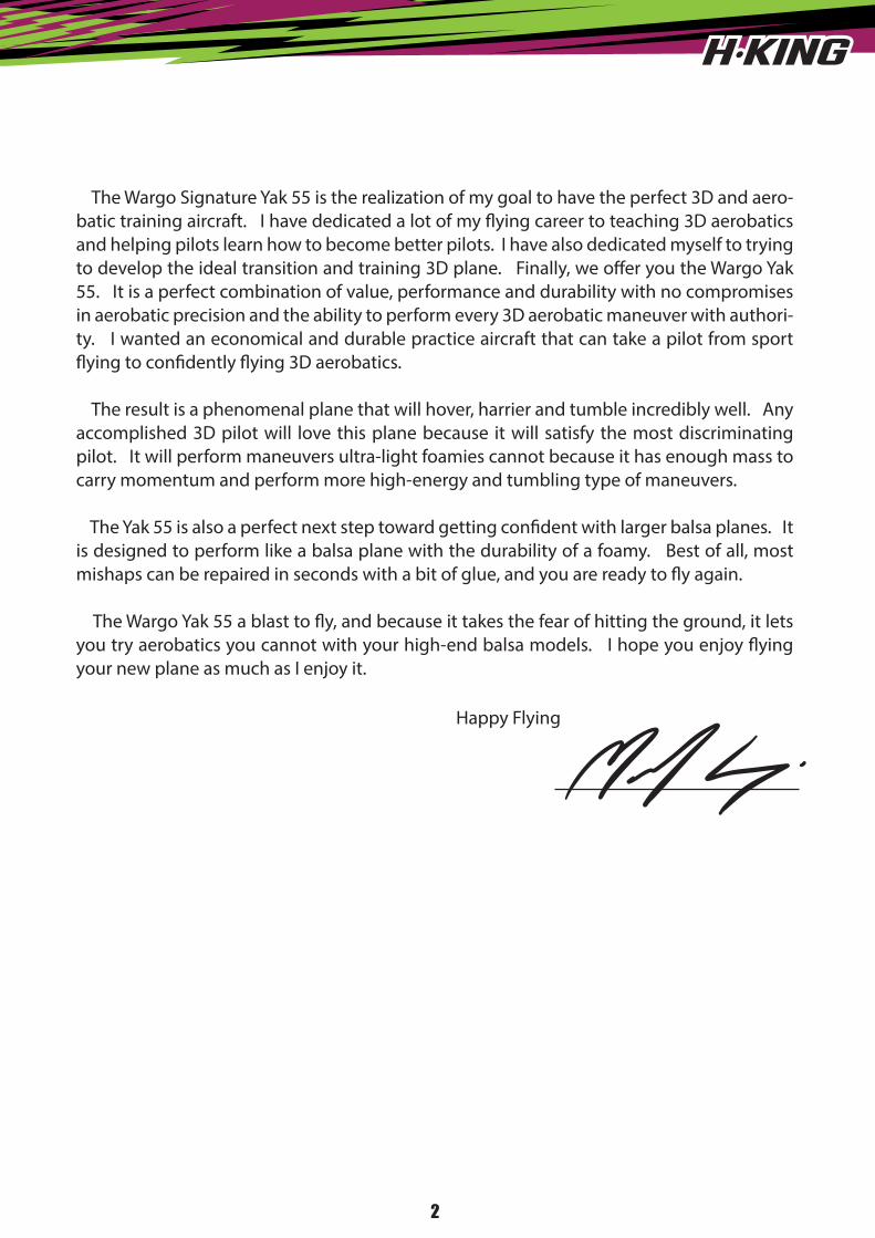
The Wargo Signature Yak 55 is the realization of my goal to have the perfect 3D and aero-batic training aircraft. I have dedicated a lot of my �ying career to teaching 3D aerobatics and helping pilots learn how to become better pilots. I have also dedicated myself to trying to develop the ideal transition and training 3D plane. Finally, we o�er you the Wargo Yak 55. It is a perfect combination of value, performance and durability with no compromises in aerobatic precision and the ability to perform every 3D aerobatic maneuver with authori-ty. I wanted an economical and durable practice aircraft that can take a pilot from sport �ying to con�dently �ying 3D aerobatics.
The result is a phenomenal plane that will hover, harrier and tumble incredibly well. Any accomplished 3D pilot will love this plane because it will satisfy the most discriminating pilot. It will perform maneuvers ultra-light foamies cannot because it has enough mass to carry momentum and perform more high-energy and tumbling type of maneuvers.
The Yak 55 is also a perfect next step toward getting con�dent with larger balsa planes. It is designed to perform like a balsa plane with the durability of a foamy. Best of all, most mishaps can be repaired in seconds with a bit of glue, and you are ready to �y again.
The Wargo Yak 55 a blast to �y, and because it takes the fear of hitting the ground, it lets you try aerobatics you cannot with your high-end balsa models. I hope you enjoy �ying your new plane as much as I enjoy it.
Happy Flying
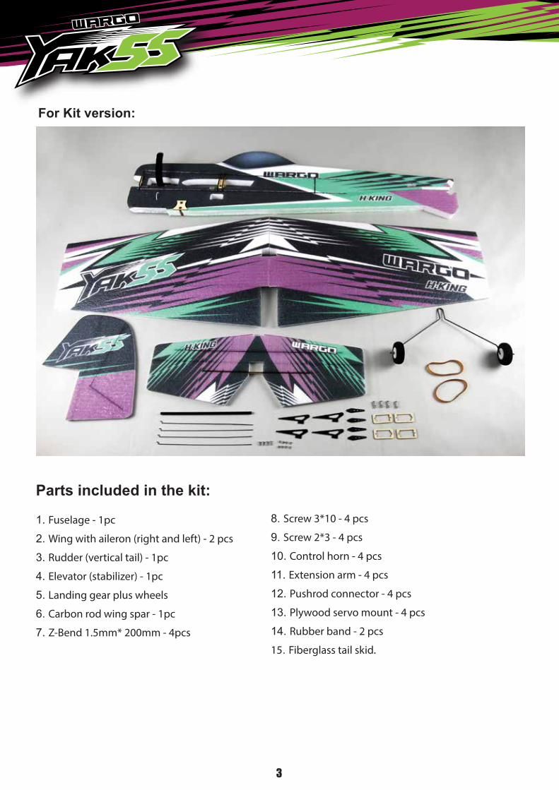
1. Fuselage - 1pc
2. Wing with aileron (right and left) - 2 pcs
3. Rudder (vertical tail) - 1pc
4. Elevator (stabilizer) - 1pc
5. Landing gear plus wheels
6. Carbon rod wing spar - 1pc
7. Z-Bend 1.5mm* 200mm - 4pcs
8. Screw 3*10 - 4 pcs
9. Screw 2*3 - 4 pcs
10. Control horn - 4 pcs
11. Extension arm - 4 pcs
12. Pushrod connector - 4 pcs
13. Plywood servo mount - 4 pcs
14. Rubber band - 2 pcs
15. Fiberglass tail skid.
3
Parts included in the kit:
For Kit version:

Fuselage length: 1080mm (42.15 in.)
Wingspan: 1096mm (43.1 in.)
Flying Weight: 690 – 760 grams (with battery)
Motor: Turnigy Aerodrive SK3 - 3530-1150kv
Brushless Outrunner Motor or HobbyKing
Donkey ST3007-1100kv Brushless Motor
ESC: Aerostar 30A Electronic Speed Controller
with 2A BEC (2~4S)
Propeller: 10*4.7 SF or 11*4.7 SF
Servo: 9-12 grams micro servo - 4 pcs
Radio: 4 or more channels
Battery: 11.1V 3S 1300 – 1800 mAh
Li-Po 25C
4
For PNF Version:
Product Specifications:

Fit the fiberglass servo extension arm onto the nylon servo arm with screws provided
We will make the right wing first. Insert the aileron servo and servo mount to the pre-cut servo slot. Ensure those servo wires are properly organised during the installation.
Apply CA glue to the servo mount.
5
1 2
3 4
5 6

Trim the excess pushrod wire with a wire cutter. Then smooth the cut with a file.
Cut a slot on the aileron strip which is perpendicular to the servo arm with a hobby knife as picture shown.
Glue the control horn as shown. Attach the “Z-bend” pushrod to the control horn and lock it with the pushrod connector.
Please repeat the above steps for the left wing.
Install the elevator servo with the servo mount as shown.
6
7 8
9 10
11 12

Install rudder servo with servo mount on the rear part of the fuselage as shown.
Cut a slot for the elevator control horn as shown .
Trail fit the elevator onto the fuselage. Ensure it is straight and level to the fuselage and main wing. Then apply CA glue to the joint between the elevator and fuselage.
Install “Z-bend” pushrod to the control horn and lock it with the push rod connector. Then apply CA glue to the control horn.
Tighten the grub screw and loctite it. Install the vertical stabiliser to the fuselage. Pleaseensure that it’s perpendicular to the horizontal stabiliser.
7
13 14
15 16
17 18

Use the same technique as shown above to prepare the control horn installation on the rudder.
Glue the rudder in place as shown.
Install “Z-bend” pushrod as shown and lock it with the pushrod connector.
Apply CA glue to the rudder horn.
Insert carbon wing spar to one of the wing panel. Then insert it to the wing mount on the fuselage and put the other wing panel on and make sure it is well balanced and true to the fuselage.
8
19 20
21 22
23 24

9
1. Connect the wings with two rubber bands as picture shown. Yon can remove the wings during transportation and for easy storage.2. Apply slow curing epoxy to the wing root, wing spar and permanent bond both wings and fuselage together for ultimate flying performance.
Install the landing gear on the gear mount.
Install the brushless motor onto the motor mount and secure it with 4 tapping screws provided with the kit.
Install the ESC onto the fuselage and secure it with a zip tie.
Secure the battery flight pack to the fuselage with the velcro band provided.
25 26
27 28
29 30
Glue the supplied fibreglass tail skid strengthener to the fuselage as shown.
There are two ways to fix the wings onto the fuselage. 1. Connect the wings with two rubber bands as shown in picture #25. You can remove the wings during transportation and for easy storage. 2. Apply slow curing epoxy to the wing root, wing spar and bond both wings and fuselage together permanently for ultimate flying performance.

1 0
C of G: 110-130mm from wing leading edge.
110-130mm
Travel Settings:
Each Flight control must be set to its physical limits. This means as far as it will go, but no farther than it has to. You set this by selecting the servo, fully deflect the surface with the transmitter, then increase (or occasionally decrease) the percentage to where the flight surface will not travel any further. Then simply back off a click or two and you are done. Then, simply deflect it in the opposite direction and repeat the process. This must always be done for Rudder, ailerons, flaps and elevators. Your travel/end point settings must be above 100% to achieve full performance from each servo.
Rates and Exponential:
All rates at 100% for full 3D flying. I suggest your expo settings for full 3D will be 60% as a starting point. Adjust to your preference after flying.
My personal settings:
I use a little trick where I put the stick at one third and set to where when I switch between rates the surface hardly changes. Obviously at the end points it is an enormous difference.My personal expo settings for low rates is in the 20% range for an aerobatic plane and half that for a war bird, and in the 60% to 70% range for high rates for 3d and near 40% for warbirds. Again, this is highly dependent on the plane and this is a general guideline only, and is my personal preference.
Please turn to the last page and get the Field Quick Guide. You can cut and
laminate and take it to the field.

NOTE
1 1

NOTE
1 2

NOTE
1 3

1 4
Field Quick guide