Yacht “Whip Jamboori” – Moody 30
24
The following report has been commissioned by Mr XX XXYYY. No liability is extended to any other person. Refer to terms and conditions at www.awsmarinesurveys.com Report Author : Andy Webb 16 St Georges Ave Dovecourt Essex CO12 3RR Tel: 07941940459 www.awsmarinesurveys.com email:[email protected] Pre-Purchase Report XX th YYYYYYY 2014 Yacht ”XXXXX” Moody 30
Transcript of Yacht “Whip Jamboori” – Moody 30

The following report has been commissioned by Mr XX XXYYY. No liability is extended
to any other person. Refer to terms and conditions at www.awsmarinesurveys.com
Report Author : Andy Webb 16 St Georges Ave Dovecourt Essex CO12 3RR Tel: 07941940459 www.awsmarinesurveys.com email:[email protected]
Pre-Purchase Report XXth YYYYYYY 2014
Yacht ”XXXXX”
Moody 30

Page 1 of 23
XX/10/14 – Sample Report 001
Contents Page Page
A.General Notes
Scope
Report Finding Process
Limitations
Survey Weather Conditions
B. Vessel Data
Dimensions, specifications & Identification
C. Hull Moulding
Hull Above Waterline
Hull below Waterline
Skin Fittings & Seacocks
Cathodic Protection
D. Deck Moulding
Side decks
Coachroof
Cockpit
Deck Apertures & Casements
Hull to Deck Joint
Rigging Attachment Points
E. Internal Structure
Internal bulkheads
Keel Root Support
Structural stiffening
Hull liners & Internal mouldings
F. Hull Appendages
Bilge Keels
Hull to keel joints
Drop Keel/centreboard
Steering system
G. Deck Hardware
Stanchions/Pulpits
Anchoring/Mooring
Winching/Cleating
Davits/Boarding Ladders
2
3
4
6
9
10
12
Other Deck Hardware
H. Rig
Spars & Fittings
Running Rigging
Standing Rigging
Sails & Canvas Work
I. Propulsion
Installation/Engine block
Stern Gear
Controls & Indicators
Exhaust System
Fuel System
Running & Service Checks
J. Onboard Systems &
Accommodation
Gas Installation
Fresh Water Tanks & Delivery
Heads
Electrical Installation
Electronic & Navigation Equipment
Heating & Refrigeration
Upholstery
K. Safety
Firefighting Equipment
Lifesaving & Emergency Equipment
Bilge Pump Arrangements
L. Additional Equipment
M. Report Summary
Recommendations
Appendices
Moisture Meter Reading
Useful Points Of Reference
13
13
16
19
19 19
22

Page 2 of 23
XX/10/14 – Sample Report 001
A. General Notes
The following Insurance Survey was carried out ashore at xxxxxxxxxxxxxxxxxxx xxxxxx xxxxxxxx
xxxxxxxxxxxxxxxxxxxxxxxxxxxxxxxxxxxxxxxxxxxxxxxxxxxxxxxxxxxxxxxxxxxxxxxxxxxxxxxxxxxxxxxxxx
xxxxxxxxxxxxxxxxxxxxxxxxxxxxxxxxxxxxxxxxxxxxxx. The vessel was seen resting on a mobile yard
cradle with four supporting arms. The mast was stepped. Access was arranged directly with the
owner.
A.1 Scope
The purpose of this survey was to carry out a pre-purchase assessment of the structural and
material condition of the vessel’s hull, equipment, superstructure, rig and engine installation.
Consideration is given to the vessel’s age, original design specification and acceptable fare wear and
tear. This survey is an indication of the vessel’s current condition as at the time of inspection and is
compiled to assist with the purchasing process of the commissioning client. This report should in no
way be interpreted as a warranty of future condition or operation .
A.2 Report Process
The vessel’s structure and associated equipment underwent a number of non- destructive tests and
visual inspection in order to detect defects. Any such defects are detailed within the appropriate
area of this report to provide context and categorised into two levels.
The first level of defects are to be considered of high significance as they may have an impact on the
safety, structural integrity or the insurability of the vessel. These items will be emphasised using
“bold point size 13” style text and will require attention as soon as practically possible.
The second level of defects noted are of a lower level of significance which can be considered as
requiring attention during the routine maintenance of the vessel. These items will be emphasised
using “bold Point size 11” style text.
In both cases, the findings are listed separately in the final Report Summary (section M) for ease of
reference. Within the categories the defects are not listed in any form of priority.
A.3 Limitations
Where parts of the vessel or associated equipment therein are covered, encapsulated, unexposed,
or inaccessible they could not be examined or tested and it is not possible for me to state that these
areas are defect free or likely to develop a future defect or malfunction. Destructive testing can
only be carried out with the owner’s written permission.
Access to the external hull area below the waterline was partly hindered by the four yard cradle
supporting arm pads. The vessel was sitting on her keel, areas at the point of contact with the yard
cradle base could not be inspected. It was only possible to remove the starboard saloon sole boards
due to rusting screw heads thereby preventing an assessment of the starboard keel matrix and
internal hull moulding surfaces.

Page 3 of 23
XX/10/14 – Sample Report 001
A rig inspection was only possible from head height down to deck level. It was not possible to run
up the main engine as this inspection was carried out ashore.
Testing the mechanical condition of the engine, the safety of the gas and safety of the electrical
systems do not form a part of this survey process.
A.4 Survey Weather Conditions
Mainly sunny, light south westerly breeze. At the time moisture readings were taken (10.45 hrs), air
temperature 19 C, humidity 63%, dew point 8.9 C, surface temperature (shaded hull) 19 C.
Conditions considered acceptable for obtaining moisture reading data.
B. Vessel Data
The Moody 30 was manufactured in the UK by the Marine Projects (Plymouth) Ltd. “XXX YYYYY”
lays to a stream mooring during the summer months and is lifted and stored ashore during the
winter season. She has been ashore for at least 12 months.
B.1 Dimensions, Specifications & Identification
The following dimensions were taken from the Moody Owners Association website and have not
been verified.
Length Overall (LOA) : 9.14 m
Beam : 3.07 m
Draft : 1.42 m
Displacement : 3674 Kgs
CIN or HIN * : Not applicable (constructed pre 1998)
Year of Construction : 1979 (approx)
Registration : None seen
Mechanical Propulsion : Yanmar 3GM30F 27 hp with indirect cooling system
Yard Hull Number : None seen
Fuel Capacity : 80 Litres (diesel) approx
Water Capacity : 2 x tanks (200 litres approx)
C E Classification : Not applicable (constructed pre-1998)
*Craft or Hull Identification number

Page 4 of 23
XX/10/14 – Sample Report 001
C. Hull Moulding
The Moody 30 hull layup is of a polyester gelcoat over laminated with of FRP (fibre reinforced
plastic) chopped strand matt and woven roving cloth consolidated with polyester resin forming a
single monolithic laminate.
The exact method for hull mould stiffening was difficult to ascertain due to limited access, evidence
of longitudinal stringers were seen. Transverse floor stiffeners constructed from FRP encapsulated
plywood are extensive throughout the bilge areas of the hull.
C.1 Hull above waterline
The surfaces of the topsides were visually inspected, acoustically tested by gently tapping with a
light 4oz hammer followed by moisture meter testing.
There was only one isolated area of damage found which straddles the waterline on the starboard
side of the hull in the midships area (refer to C.2).
The moisture test was carried out using a “Sovereign Quantum Marine” moisture meter at 1 metre
intervals above the waterline. These readings were between 15-18 shallow and 13-17 deep which
are considered normal. Refer to “Appendices” for further description of use of moisture meters and
descriptive table of results for ‘shallow’ readings.
Internally an inspection in the anchor locker revealed a previous repair which proved sound and
externally is of a high standard. Refer to picture in section D.6. No action required.
C.2 Hull Below Waterline
The below waterline inspection process uses the same methods as above the waterline. A visual
inspection revealed no areas of hull distortion. The four hull supporting pads were firmly braced
and could not be removed to allow inspection of the area behind. The hull has been coated with
many layers of antifouling and below this an epoxy coating.
One area of impact damage has fractured the
epoxy and gelcoat layers of the hull skin. Hammer
sounding indicates the likely hood of delamination
within the outer layers of the hull laminate. The
paint coatings and gelcoat should be
ground back to reveal the underlying
laminate for assessment. If required,
damaged laminate should be ground out
with a bevelled edge ratio of 15:1 and
replaced with a polyester layup, filled,
fared then re-gelcoated and finished. Epoxy coating re-applied to underwater
section after polyester has cured (temperature dependent – suggest repair as soon
as possible and apply epoxy during the spring).

Page 5 of 23
XX/10/14 – Sample Report 001
Moisture meter readings were taken at one metre intervals throughout the below waterline hull
area on prepared areas where the antifouling had been removed by dry scraping. The readings
ranged from 20-31 on shallow and 16-29 on deep. These readings were considered acceptable,
however, there is the possibility of distortion of these readings from the extremely thick epoxy
coating.
Refer to “Appendices” for further description of use of moisture meters and descriptive table of
results for ‘shallow’ readings.
C.3 Skin Fittings & Seacocks
A visual inspection of the vessel’s exterior confirmed a total of eleven skin fittings, three above the
waterline and eight on or below, this excludes the anchor locker drainage skin fitting. Each fitting
with its’ associated components (valve/tail pipe) was tested by some or all of the following methods
both inside and outside the hull as appropriate, a visual inspection (paint coatings removed if
appropriate), light hammer sounding, actual operation to assess free movement, assessment of
hoses and attachment clips for security, manual application of pressure to the fitting by hand to
stress test the structure .
No skin fittings or valves were dismantled as part of this survey nor tensions on hose clip screws
altered. Defects found are detailed within the following table. Use the reference number in
conjunction with the photographs for further reference :
Ref. No
Description Location Noted Fault & Corrective Action Required - High Significance
1 Engine Cooling water intake ball valve –Yellow metal (composition unconfirmed)
Below waterline – access under cockpit sole locker
Valve handle locating machine screw sheered. Handle corroded. Replace valve with a de-zincification resistant (DZR brass) alternative. Strainer inspection cover removed, strainer requires cleaning.
2 Heads discharge skin fitting, Yellow metal (composition unconfirmed)
Below W/L to starboard Early signs of dezincification – Remove bonding cable from valve fitting situated under starboard saloon frwd settee – monitor annually, valve stiff to operate- lubrication required.

Page 6 of 23
XX/10/14 – Sample Report 001
C.4 Cathodic Protection
Cathodic protection is maintained by one pear shaped anode mounted between the rudder and keel
on the underside of the hull to starboard. The anode is active as signs of wasting is present but not
sufficient to require replacement. The attachment studs were hammer tested and found to be
serviceable.
A continuity test with a multi meter was carried out between the anode and the prop shaft,
connectivity was confirmed.
Bonding between the engine block and anode is present, the wire connector terminal used for the
anode internal fastening stud connection is disintegrating, long term the cathodic protection will
steadily diminish therefore it would be wise to replace the earth cable with an uprated marine
spec. tinned type cable and fittings.
D Deck Moulding
The deck moulding incorporates the cockpit, coamings and coach roof in one piece. The deck layup
consists of polyester gelcoat over laminated with chopped strand matt, woven rovings with,
localised areas of end grain balsa wood core stiffening and plywood backing pad inserts.
D.1 Side Decks
The side decks have original gelcoat finish and underwent a visual inspection of the exterior
surface, collection of moisture readings, acoustic hammer sounding and a weight bearing load test
of the deck under foot to ascertain if there were any delaminated “soft” spots on the underlying FRP
deck structure.
The visual inspection revealed a number of superficial areas of crazing in the gelcoat skin, previously
filled areas of cosmetic damage and backfilling of previous fastening holes for removed fittings.
These imperfections are considered acceptable on a vessel of this age and could be improved at the
new owner’s discretion. The gelcoat finished has become very dull due to UV degradation which
can be remedied by a machine compound and polish.
Table Ref 1 Table Ref 2

Page 7 of 23
XX/10/14 – Sample Report 001
There are a four holes unfilled along the outboard face of aft coaming which
require filling by bevelling the edge of the holes with a countersink drill bit,
applying a backing layer of masking tape on the underside of the FRP (accessible
through the cockpit sole locker) then applying gelcoat filler mix re-inforced with
glass fibre strands, then once faired, overcoat with colour matched gelcoat.
The acoustic and weight bearing tests revealed no defects, the moisture test readings taken at
random points fell well within the anticipated levels 15-18 shallow and 14-16 deep). Particular
attention was given to the areas around the exit points of the shroud adjuster plates were readings
were marginally higher topping 25 in shallow and 28 on deep. This is still acceptable but may
indicate that a small amount of moisture is weeping in under the stainless steel deck mounted
capping plates. To protect the structural integrity of the plywood of the fore cabin bulkhead I
recommend the removal of the capping plates and raking out of the original silicon sealant and
replace with a polyurethane adhesive sealer (e.g. Sikaflex 291) .
D.2 Coachroof
The coachroof underwent the same testing procedure as the side decks and no defects were found
other than cosmetic/superficial gelcoat imperfections.
The raised plinth moulded into the cabin coachroof for mounting the aluminium mast step showed
no signs of defect.
D.3 Cockpit
The cockpit is equipped with four seat lockers, cave lockers in the coamings and one large access
hatch forming part of the cockpit sole. Cosmetic crazing and minor chips were seen on the
gelcoated surfaces. Testing as per the coachroof revealed no defects.
D.4 Apertures & Casements
The main cockpit companionway is equipped with a horizontal sliding lid housed in the deck
moulding of the main cabin top with three vertical standing wooden washboards and is locked with
a hasp/staple and padlock. The stainless steel guide rails for the wooden washboards are
detaching from the deck moulding due to missing/loosened screws, these require attention from a
security aspect and potential ingress of moisture and will require removing, re-bedding and
refastening on an adhesive sealant.
The forecabin is serviced by a cabin top mounted hinged access hatch. The acrylic glazing is
showing signs of severe UV degradation but due to the thickness of the material the water tight
integrity and strenght of the material is still at an acceptable level. It is recommended that
consideration be given replacing the acrylic panel as part of the ongoing programme maintenance
of the vessel.
The adjustable stay rod which sets the hatch lid opening position as become detached from the
internal wooden frame. The hole for the self-tapping screw fastening should be back filled with
epoxy the screw in place, when cured, remove the screw then reattach the stay rod.

Page 8 of 23
XX/10/14 – Sample Report 001
The coachroof sides are each fitted with an aluminium framed clear acrylic glazed window. The
acrylic is showing signs of UV degradation and will require monitoring with a view to long term
replacement. The frame to glazing join has been resealed with silicon and should be monitored for
water ingress regularly.
Hose testing of the aforementioned items in this section was not carried out as part of this survey
process.
The cockpit is equipped with two cockpit lockers both port and starboard integral with the
starboard cockpit seating and can be securely padlocked if required. There are small cave locker
apertures to port and starboard mounted in the cockpit coamings.
The majority of the sole of the cockpit consists of one large aft hinged hatch. A pedestal base for
the cockpit table is through fastened with bolts and the underside backing washers have corroded
and will soon fail allowing the fastenings to loosen and the breakdown of the watertight seal
which will allow water ingress. The backing washer should be replaced with A4 grade stainless
steel penny washers.
The deck moulding incorporates the moulded access for the anchor well with hinged lid. Drainage
within the locker was active.
D.5 Hull & Deck Joint
The deck and hull joining method consist of an integral flange on the hull moulding which allows the
deck do be landed on a joining compound. The joint is capped by an aluminium toe rail which is
bolted through both deck and hull mouldings proving additional fastening. Where visually
accessible the joint was in a stable condition.
D.6 Rigging Attachment Points
The forestay attachment point is incorporated
with the bow roller arrangement and is through
bolted into the stem and foredeck. Fastenings
were visible within the anchor locker and one is
showing signs of corrosion. Due to the high
loading at this attachment point I recommend
the removal and replacement of the corroded
bolt with an A4 grade stainless steel
replacement and the removal of an adjacent
bolt to inspect for crevice corrosion, if present I
suggest the replacement of all the bolts.
All remaining rigging attachment points were tested by swigging the rigging wires and looking for
excessive movement or flexure in the FRP deck/hull mouldings together with a visual inspection and
hammer sounding of fastenings as appropriate. Due to internal linings it was possible to inspect
the baby forestay or shroud attachment point backing arrangements. The securing nuts for the
backstay attachment are corroding and should be replaced with A4 grade nyloc nuts.
previous repair
Page 9 of 23
XX/10/14 – Sample Report 001
E Internal Structure
The vessel hull moulding is stiffened by way of longitudinal stringers coupled with transverse
stiffeners and floors moulded from FRP encapsulated plywood with plywood full and part bulkheads
which also supply support to the deck and hull mouldings. The exact layout and composition could
not be determined due the restrictions of access by way of hull lining, flooring and cabinetry.
E.1 Internal Bulkheads
Bulkheads within this hull were difficult to fully inspect due to the overlapping hull lining materials
and outlined restrictions above. Where access was obtained the bulkheads were laminated to the
surface of the inner hull face on both sides. The FRP bonding was covered with flowcoat for
protection and finish. An access hole cut into the main cabin bulkhead for the shower bilge pump
outflow pipe, between the heads and saloon, starboard side, accessible under the bench seating
has suffered from moisture ingress through excessive bilge water levels. This compartment and
general bilge areas should be fully dried out and dehumidified over the winter period. When the
plywood has dried sufficiently a coating of epoxy should be applied to prevent future moisture
ingress and arrest the potential for wet rot of the structural bulkhead (see picture page 10).
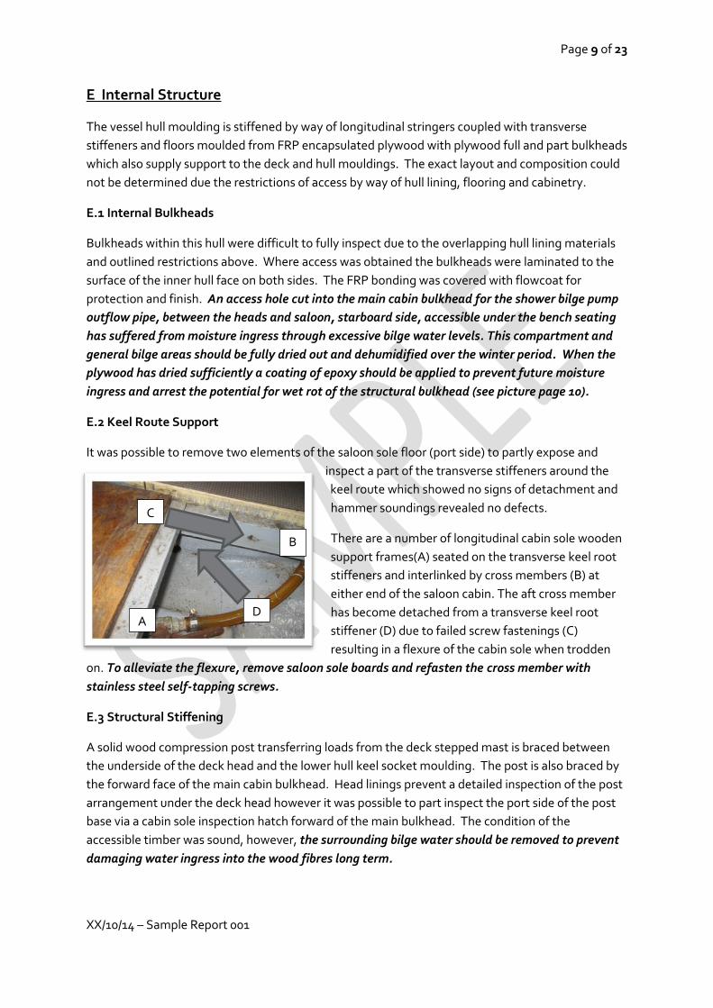
E.2 Keel Route Support
It was possible to remove two elements of the saloon sole floor (port side) to partly expose and
inspect a part of the transverse stiffeners around the
keel route which showed no signs of detachment and
hammer soundings revealed no defects.
There are a number of longitudinal cabin sole wooden
support frames(A) seated on the transverse keel root
stiffeners and interlinked by cross members (B) at
either end of the saloon cabin. The aft cross member
has become detached from a transverse keel root
stiffener (D) due to failed screw fastenings (C)
resulting in a flexure of the cabin sole when trodden
on. To alleviate the flexure, remove saloon sole boards and refasten the cross member with
stainless steel self-tapping screws.
E.3 Structural Stiffening
A solid wood compression post transferring loads from the deck stepped mast is braced between
the underside of the deck head and the lower hull keel socket moulding. The post is also braced by
the forward face of the main cabin bulkhead. Head linings prevent a detailed inspection of the post
arrangement under the deck head however it was possible to part inspect the port side of the post
base via a cabin sole inspection hatch forward of the main bulkhead. The condition of the
accessible timber was sound, however, the surrounding bilge water should be removed to prevent
damaging water ingress into the wood fibres long term.
A
B
D
C
C

Page 10 of 23
XX/10/14 – Sample Report 001
E.4 Hull Liners & Internal Mouldings
There are a number of FRP internal hull mouldings forming the seating, bunk and heads
arrangements including the main water storage tank which forms the base of the quarter berth.
Where accessible, all mouldings were assessed visually, the bonding arrangement to the hull
structure was hammer sounded. No defects were found to surfaces of the mouldings.
The FRP bonding of the forward saloon starboard seating liner to the veneer effect plastic coating
of the main bulkhead is failing. This is not deemed to be of any structural significance but can be
rectified by applying epoxy resin between the FRP skin and bulkhead to re-bond.
The following pictures inidcate the areas of dedonding, the black handled flat blade scraper
indicates the position and scale of the de-bonding.
F. Hull Appendages
F.1 Fin Keel
The fin keel is manufactured from cast iron. A visual inspection did not reveal any major defects. It
was not possible to inspect the full length of the underside of the keel. There did not appear to be
any signs of serious surface degradation outside the normal parameters expected for keels fitted to
this age of vessel.
Recommendation E.1 page 9
Page 11 of 23
XX/10/14 – Sample Report 001
The keel shoe is fitted with transvers pairs of keel studs, the heads with associated nuts and backing
plates are encapsulated with FRP in the bilge area. It was not possible to visually inspect all of the
stud heads, those accessible were hammer sounded and there were no signs of rust staining or
cracking within the flowcoated FRP encapsulations seen.
F.2 Hull To Keel Joints
Due to the vessel sitting on her keel the hull to keel joint was viewed in compression. This does not
give a complete indication of the joint condition or structural integrity as the keel studs and landing
seems are normally placed under tension when the vessel is afloat. The landing seam (mastic/filler
between the keel to hull contact point) is in a serviceable condition, some of the fairing has broken
away, considered cosmetic .
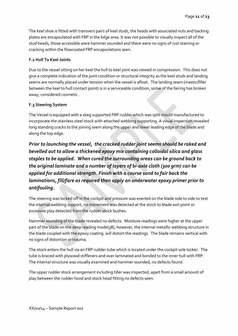
F.3 Steering System
The Vessel is equipped with a skeg supported FRP rudder which was split mould manufactured to
incorporate the stainless steel stock with attached webbing supporting. A visual inspection revealed
long standing cracks to the joining seem along the upper and lower leading edge of the blade and
along the top edge.
Prior to launching the vessel, the cracked rudder joint seems should be raked and
bevelled out to allow a thickened epoxy mix containing colloidal silica and glass
staples to be applied. When cured the surrounding areas can be ground back to
the original laminate and a number of layers of bi-axle cloth (300 grm) can be
applied for additional strength. Finish with a course sand to fair back the
laminations, fill/fare as required then apply an underwater epoxy primer prior to
antifouling.
The steering was locked off in the cockpit and pressure was exerted on the blade side to side to test
the internal webbing support, no movement was detected at the stock to blade exit point or
excessive play detected from the rudder stock bushes.
Hammer sounding of the blade revealed no defects. Moisture readings were higher at the upper
part of the blade on the deep reading mode(38), however, the internal metallic webbing structure in
the blade coupled with the epoxy coating will distort the readings. The blade remains vertical with
no signs of distortion or trauma.
The stock enters the hull via an FRP rudder tube which is located under the cockpit sole locker. The
tube is braced with plywood stiffeners and over laminated and bonded to the inner hull with FRP.
The internal structure was visually examined and hammer sounded, no defects found.
The upper rudder stock arrangement including tiller was inspected, apart from a small amount of
play between the rudder hood and stock head fitting no defects seen.

Page 12 of 23
XX/10/14 – Sample Report 001
G. Deck Hardware
G.1 Stanchions/Pulpit/Push pits
All found to be defect free.
G.2 Anchoring & Mooring
All mooring cleats mooring cleats were visually checked, hammer sounded and load tested. No
defects found.
The vessel is equipped with two anchors. The main bower anchor is a 12KG CQR plough anchor
stowed in the recessed foredeck anchor well. The 8mm anchor chain is stowed below the well via a
chain pipe into a chain locker, accessible via an inspection panel in the forecabin. The anchor chain
was not removed for inspection and the method by which the bitter end is established cannot be
confirmed.
The bower anchor to chain shackle is severely corroded and should be replaced. A
number of the above chain locker stowed chain links have begun to corrode and
should be cut away from the main cable.
The second stream anchor is a danforth of approximately 8KG stored in the aft port side
cockpit locker with attached warp. The anchor warp thimble is corroded and requires
replacement.
There are numerous warps of varying lengths and diameters suitable for mooring
complimented by fenders stowed in the aft cockpit lockers.
G.3 Winching/Cleating
All deck and mast mounted winches were operated , not under load, and found to be serviceable.
G.4 Davits/Boarding Ladder
A folding boarding ladder is securely fastened to the stern of the vessel. A visual inspection of the
backing pad arrangements revealed severe corrosion of mild steel plates. As these plates
disintegrate the ladder will become loosely attached allowing water in and damage to the
surrounding laminate. The backing nuts should be removed and replacement backing plates
manufactured from 316 stainless should be fitted by bedding on marine adhesive sealant and new
locking nuts.
G.5 Other Deck Hardware
The vessel has a cockpit coaming mounted stainless steel tube for supporting a TV areal. Found
secure.

Page 13 of 23
XX/10/14 – Sample Report 001
H Rig
H.1 Spars & Fittings
The vessel has is a mast head rig (Bermuda Sloop) and is equipped with roller reefing. The mast is
aluminium and supported by two pairs if inline spreaders. Both mast and boom (aluminium) are
anodised and were visually inspected and found straight and true. The mast could only be inspected
up to shoulder height.
All fittings attached to the mast and boom are firmly riveted. The gooseneck shows no signs of
excessive wear.
The headsail is mounted on a Colnebrook roller reefing system. The halyard attachment swivel
requires lubricating to prevent jamming.
H.2 Running Rigging
In general the running rigging is in good order suffering only from cosmetic dirt and grime. The
majority of the rope is a braid on braid polyester based construction. It was not possible to inspect
the lengths of running rigging housed within the mast.
H.3 Standing Rigging
The standing rigging is manufactured from 1 x 19 strand 316 grade stainless steel wire of 7 mm
diameter. The inner forestay is made from 5mm diameter wire.
Mr Russell advised that the standing rigging was replaced three years ago. A visual inspection up to
shoulder level was carried out and no defects were found. It was not possible to check the forestay
as it is encapsulated by the jib luff foil.
There are four guard wires running down the length of the vessel from the pushpit to pulpit are
constructed from 4mm diameter 1 x 19 stainless steel wire with Sta Lok type terminals. The lay of
the wire on the forward upper starboard guardrail has receive some trauma which has unlayed the
wire strands, none are broken. The guard wires should be inspected regularly and replaced if
broken wire strands are detected.
H.4 Sails & Canvas Work
The headsail, mainsail and cruising spinnaker were seen below together with a spray hood. It was
not practical to fully inspect the cruising chute, which appears to be quite new. The mainsail was in
an “as new” condition and the headsail in very good condition with no repairs required .
I. Propulsion
The auxiliary propulsion for this vessel is provided by a Yanmar 3GM30 3 cylinder diesel engine and
reduction gearbox with cooling provided by an indirect closed circuit fresh water heat exchanger
system.

Page 14 of 23
XX/10/14 – Sample Report 001
I.1 Installation & Engine Block
The engine space and access is limited. To visually inspect, the companionway steps are removed to
view the front end of the engine block and an FRP cover below the cockpit sole hatch is removed to
view the aft end of the engine.
The engine mounting was inspected, no faults were found with the engine bearers or feet.
The engine and gear box oil levels were checked. The engine oil is due for a change and the gear box
oil appears to be over filled. The inside surface of the filler cap housing was checked for emulsified
oil, all clear. The header tank fluid was up to operational level, it was not possible to check for a
coolant additive. The general condition of the engine block paintwork is good, there is a fine
coating of black dust which could be from the alternator belt which is slightly loose.
The rear covering panel has cut outs for the cooling water intake hose, engine control cabling and
engine stop cable which are all showing signs of chafe where they pass through the FRP cover.
There is also a chafe problem developing with the cooling water intake hose at the forward end of
the engine box. To prevent further damage and potential failure of these items the apertures
should be modified together with more efficient application of pipe clips to remove the
pressure/contact chafe points .Failing of the cooling water hose could lead to overheating of the
engine and filling the bilges with seawater.
Stop cable chafe point
Engine cooling
water intake pipe
squeeze/chafe point
Engine control cable chafe point
Page 15 of 23
XX/10/14 – Sample Report 001
I.2 Stern Gear
The vessel is equipped with a one inch stainless steel propeller shaft supported externally by a P
bracket with integral cutlass bearing, no excessive play detected within bearing and the P bracket
was firmly attached to the hulls’ structure. The shaft enters the hull via an FRP recess in the hull
moulding with a through bolted yellow metal shaft housing, hammer tested, no defects found.
The shaft mounting flange and shaft are sealed by a Volvo rubber shaft seal which is water
lubricated but requires greasing annually and must be “burped” of air when the vessel is launched.
A triple bladed right hand 14” propeller (assumed cast from a bronzed based alloy) is attached to
the shaft by a stainless steel castellated nut and locking split pin. When hammer sounded a good
return was received, no stress cracking evident. The propeller shaft was rotated by hand no visual
signs of misalignment were seen or unnecessary friction felt. No signs of pitting corrosion seen on
exposed areas of the shaft, which cannot be confirmed as defect free unless totally withdrawn from
the vessel and propeller removed to allow full inspection.
I.3 Controls & Indicators
The primary engines controls and indicators are located within the cockpit. The engine panel was
powered up, glow plug indicator, alternator warning light and audio alarm test panel indicators
were operational, the start button could not be tested. The throttle/gear selector lever was tested
and all cable linkages to the engine and gearbox responded.
As detailed in section I.1, there are chafing issue where the control cables enter the engine space,
the stop cable in particular has suffered damage to the outer casing and will require monitoring .
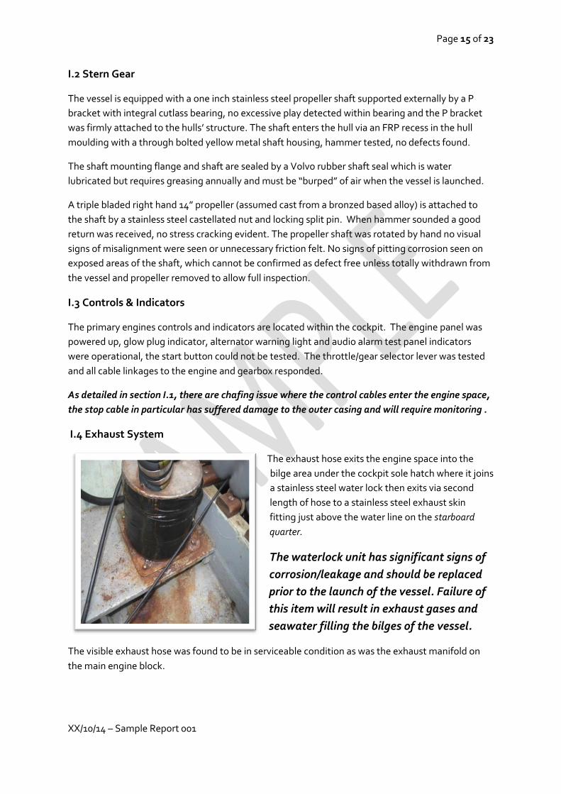
I.4 Exhaust System
The exhaust hose exits the engine space into the
bilge area under the cockpit sole hatch where it joins
a stainless steel water lock then exits via second
length of hose to a stainless steel exhaust skin
fitting just above the water line on the starboard
quarter.
The waterlock unit has significant signs of
corrosion/leakage and should be replaced
prior to the launch of the vessel. Failure of
this item will result in exhaust gases and
seawater filling the bilges of the vessel.
The visible exhaust hose was found to be in serviceable condition as was the exhaust manifold on
the main engine block.

Page 16 of 23
XX/10/14 – Sample Report 001
I.5 Fuel System
The diesel fuel is stored in a painted alloy tank mounted under the port cockpit seating. No leaks or
corrosion were detected from the visible areas of the tank’s surfaces, the mounting arrangement
remains firm when pressure was applied to the tank.
The flexible fuel delivery pipework is manufactured to the ISO 7840 standard.
I.6 Running & Service Checks
It was not possible to test run engine as part of this survey. It is recommended that a marine
engineer be consulted with a view to carrying out a full inspection and servicing of the engine
installation.
J. Onboard Systems & Accommodation
J.1 Gas Installation
The forward port hand cockpit locker is fitted with a moulded FRP liner which holds two propane
gas bottles. Escaping gas will drain from the locker via a vent at its base into the cockpit, which in
turn will escape the vessel via the cockpit drains.
The gas regulator, high pressure delivery hose, armoured delivery hose to cooker,
and pressure gauge/flow regulator are either in poor condition or beyond
recommended service life and require replacement (hose dated April ’97).
The gas delivery copper pipe is separated into two supply lines via a ‘T’ fitting within the gas locker.
One of these copper lines is redundant and terminates under the gas cooker (left picture).
The gas system should not be pressurised until the redundant copper pipe is
correctly blanked off and preferably removed as part of a refurbishment of the gas
installation by a Gas Safe Registered Engineer.

Page 17 of 23
XX/10/14 – Sample Report 001
The sole gas appliance located in the main cabin which is a Plastimo Neptune 2500 hob/oven/grill
unit which is fitted with flame failure cut off devices. There is no isolation valve present within the
cabin space for the cooker which should be installed as part of the gas system refurbishment
The gas system on this vessel was not operated or tested as part of this survey. In view of the
age and condition of the essential system components, a Gas Safety registered
engineer should be instructed to inspect and refurbish the gas installation.
J.2 Fresh Water Tanks & Delivery
The vessel is equipped with a pressurised water system with was activated and all faucets
found operational. The vessel is equipped with two water tanks sharing a common filling
point. The main tank is fitted to the starboard side of the vessel forming the base of the
quarter berth, it was not possible to inspect the tank fully due to access limitations.
The second tank is situated in the lazzorette and is currently secured by fenders
wedging it in place against the rudder tube due to the failure of the retaining
screws of the two webbing securing straps. The straps should be re-fastened with
higher specification A4 stainless steel screws.
The hose systems used for the fresh water delivery are showing signs of degradation. The
main filler hose from the deck mounted filler cap to the aft water tank is unsupported with pipe
clips and has a loop in the system which falls below the level of the water tank which creates a
trap for water which can become stagnant, the hose wall has collapsed. Replace the hose.

Page 18 of 23
XX/10/14 – Sample Report 001
J.3 Heads (WC)
The heads is fitted with a Lavac manual pumping toilet found securely fastened to the FRP internal
liner. All hose clips found in sound condition and free from corrosion. The inflow and discharge
pipework is looped above the waterline to form a swan neck. The system could not be operated
ashore to assess the condition of the pump and for signs of leaks. An anti-syphon measure has been
taken on the inflow pipe as per the manufacturer’s installation guidelines.
The heads sole has drainage into a bilge compartment in the main saloon and is serviced by a jabsco
12 volt bilge grey water pump with float switch and found to be non- operational and disconnected
from an outflow seacock. Until the pump system is working, consideration should be given to a
method by which the shower head/tap faucet cannot be removed and used un-intentionally.
J.4 Electrical Installation AC & DC
The 240 volt AC system is fitted with a 240 volt RCD breaker with test switch with two circuit
breakers. The 240 volt system was not tested as part of this survey process.
The DC system on this vessel is 12 volts supplied by two batteries located under the cockpit sole
hatch. The main battery is housed in a battery box however, the lid requires alteration to allow a
correct fit with an adequate system of fastening the lid applied in order to retain the battery in
safely in position. The battery was found to be dry and requires replacement.
The secondary battery is lashed with rope to a timber framed shelf in the lazzorette area and does
not have protection over the terminals which are also suffering from corrosion. I suggest that a
battery box should be purchased and installed securely and the terminals of the battery and
cabling cleaned of corrosion. The secondary battery was holding a charge and allowed the testing
of 12 volt onboard equipment. The battery bank is charged via an engine mounted alternator and a
240 volt mains supplied charger secured adjacent to the main battery box, thesewere not tested.
The battery bank is controlled by a rotary selector switch with isolator key below. The DC power
supply is distributed via an Axon fused switch panel situated at the navigation station.
J.5 Electronic & Navigation Equipment
The battery isolator switch was engaged and all switch panel circuits individually powered up and
found to be operational with the exception of the following reported defects and observations.
Operation of the navigation light switches revealed that the pulpit mounted bi-colour navigation
light and the mast head navigation light are not operational and require further investigation and
fault rectification prior to sailing at night.
The onboard mounted navigation equipment was powered up and assessed within the limitation of
the vessel lying ashore. No defects found. The DSC VHF was receiving loud and clear, a
transmission test was not carried out.
J.6 Heating & Refrigeration
There is no installed heater or refrigeration unit on board this vessel.

Page 19 of 23
XX/10/14 – Sample Report 001
J.7 Upholstery
The upholstery within the entire vessel appeared to be generally in good condition.
K. Safety
K.1 Firefighting Equipment
Two fire extinguishers were located on board, it was not possible to confirm their date of expiry.
The contents pressure gauge was showing “green”. If the expiry date cannot be confirmed the
extinguishers should be replaced. Refer to the RYA Boat Safety Handbook (G103) for further
guidance and request advice from the retailer on the best product selection for this vessel.
K.2 Lifesaving & Emergency Equipment
The vessel is equipped with numerous flares located in the after portside cockpit locker and the
nave station locker, all of which had an expired service date and must be replaced. Refer to the
RYA Boat Safety Handbook (G103) for further product guidance and handling advice and disposal of
the existing flares. Some chandlers/retailers may offer to exchange dated flare packs for new
purchases and offer advice on the most suitable product selection.
A horseshoe life buoy is mounted on the port pushpit with a working floating light, I recommend
the light is attached to the buoy by a lanyard.
K.3 Bilge Pump Arrangements
A manually operated bilge pump is located on the underside of the aft cockpit sole with a
deck mounted access port for the pump handle which is located in the nav station cave
locker. The pump was operational but could not be tested due to in sufficient water at the
hose intake point. The bilge pump hose would benefit from the addition of a strum box and hose
clip arrangement to allow a more effective positioning of the intake aperture to facilitate greater
pumping efficiency, then tested. This is the primary means of pumping out the vessel.
As mentioned in J.3, the jabsco 12 volt float switch controlled bilge pump arrangement is not
operational.
L. Additional Equipment
L.1 Tender & Associated Equipment
An inflatable tender was found stowed on top of the quarter berth bunk and was not
inspected as part of this survey.
M. Report Summary
“Whip Jamboree” is a well equipped vessel which has experienced an ongoing programme of
improvements under the current ownership.

Page 20 of 23
XX/10/14 – Sample Report 001
M.1 Recommendations – High significance requiring rectification as soon as is practical
(C2 p4) Carry out repairs to impact damage on starboard waterline (midships).
(C.3 p5) Replace engine cooling water gate valve with a de-zincification resistant (DZR)
alternative.
(D.1 p7) Fill the four holes on the outboard face of the cockpit coaming.
(F.3 p11)The cracks within the rudder blade join must be raked out and repaired with epoxy
based FRP materials
(G.2 p12) Replace the bower anchor attachment shackle and remove the piece of exposed
/corroded anchor chain.
(I.4 p15) Replace the exhaust system waterlock unit.
(J.1 p16) Refurbish gas installation delivery hoses and cap off redundant pipework (work
should be carried out by a Gas Safety Registered Engineer). The gas installation should not
be used until inspected and faults identified rectified.
(J.2 p17) The secondary water tank located in the lazarette requires re-fastening to the hull’s
structure to prevent movement.
(J.4 p18) Replace the primary battery with a new unit.
M.2 Recommendations – General Maintenance / Advisory
(C.3 p5) Remove cathodic protection bonding wire from heads discharge skin fitting and
lubricate the ball valve using a spray lubricant to free up the movement.
(C.4 p6) Replace engine block to anode earth cable with a higher specification marine grade
(tinned) cable
(D.1 p7) Remove the shroud attachment point capping plates and rake out original silicon
and re-bed using a polyurethane marine adhesive sealant.
(D.4 p7) Remove the stainless steel guide rails rom the companion way, re-bed using
polyurethane adhesive sealant with full complement of self- tapping A4 grade stainless
steel screws.
- Consider replacement of foredeck hatch acrylic glazing.
- Foredeck hatch adjustable stay rod mounting screw should be re-bedded with epoxy

Page 21 of 23
XX/10/14 – Sample Report 001
- Replace the backing washers for the cockpit table pedestal base mount on the cockpit
sole hatch using A4 grade stainless steel washers.
(D.6 p8) Remove corroded forestay attachment fitting bolt and replace, withdraw an
adjacent bolt and inspect for corrosion, if found, inspect all bolts and replace as required
with A4 grade stainless steel specification material, re-bed all with polyurethane adhesive
sealant.
- The upper two fastening nuts and washers of the backstay attachment plate are
showing signs of corrosion and should be replaced and re-bedded as above.
(E.1 p9) Apply a protective coat of epoxy resin to the access hole in the main cabin
bulkhead between the bilge of the heads and main cabin once the plywood has been dried
(E.2 p9) Remove the saloon cabin sole boards and reattached the transverse floor support
frame to the structural transverse keel root stiffener with A4 grade stainless steel self -
tapping screws bedded on sealant.
(E.3 p9) Remove all water from the bilges and monitor levels to prevent moisture damage to
the timber elements of the vessel and potential osmotic activity. Use a dehumidifier to
assist with the process.
(E.4 p10) Apply epoxy resin to the de-bonded FRP tabbing flanges of the starboard side
forward seating liner to main cabin bulkhead surfaces.
(G.2 p12) Replace the corroded thimble of the stream anchor warp.
- Remove the bower chain from the locker and inspect for corrosion and security of the
bitter end.
(G.4 p12) Replace the corroded backing plates of the boarding ladder with 316 grade
stainless steel alternatives bedded on polyurethane adhesive sealant.
(H.1 p13) Lubricate the roller furling jib halyard attachment swivel with a dry silicon
lubricant.
(H3 p13) Maintain regular inspections of the guard wires, in particular the forward end of the
upper starboard wire at its terminal. Replace when broken strands detected.
(I.1 p14) Carry out a full review of the entry/exit points of all hoses and control cables within
the engine bay in order to alleviate chafe points by way of the addition of suitable
mounting clips and adjustment to apertures of the engine bay covers

Page 22 of 23
XX/10/14 – Sample Report 001
(I.6 p16) Consult a marine engineer with a view to carrying out a full inspection and service
of the engine installation.
(J.2 p17) Replace the freshwater filler hose with adequately supported reinforced water
hose avoiding low points in the supply run to the aft tank.
(J.3 P18) A method to prevent the accidental usage of the shower faucet other than as a tap
facility for the wash basin should be put into place.
(J.4 p18) Carry out alterations to the main battery box lid to ensure a correct and secured fit.
Install a battery box unit with securing straps for the secondary battery. Clean the
corrosion from the cable connectors and terminals of the secondary battery.
(J.5 P18) Investigate and rectify the faults with the mast head and pulpit mounted
navigation lights prior to night sailing.
(K.1 p19) Confirm the expiry dates of the onboard fire extinguishers and replace if
necessary.
(K.2 p19) Replace all date expired distress signalling flares. Connect the floating light to the
horeshoe life buoy with a lanyard.
(K.3 p19) Improve the main bilge pump hose efficiency by adding a strum box and providing
adequate support with hose mounting clips for better placement of bilge water extraction
point. Test the pump with water throughput.
Appendices
Moisture Meter Readings
To determine both shallow and deep seated moisture of a solid skin FRP laminate I rely on a
moisture metre using capacitance technology developed specifically for the Marine Surveyor’s
application by a company called “Sovereign”. The model used to determine the data collected in
this survey was the ”Quantum Marine” with the series 4.0 edition software. The scale of readings
range from 0-100, the numbers recorded are not representative of moisture content as a
percentage of dry weight, rather a relative scale set by the equipment manufacturers by which all
such metres are calibrated and regularly checked .The table below will offer a more meaningful
understanding of the numbers obtained in this report. These are to be compared with readings
taken in “shallow” mode, for solid laminates.
Reading Guideline
0-15 Considered dry
16-20 Moisture present at low levels, no concern
21-30 Risk of associated moisture defect consider medium, at the top of this range levels are becoming significant
31-45 Considered high and at a level where the risk of moisture related defects are present

Page 23 of 23
XX/10/14 – Sample Report 001
is significant but not yet physically detectable
46-60 Very high and is usually accompanied by physically detectable signs.
61-80 Extremely high and indicative of possible laminate damage in addition to osmotic blistering and physically detectable signs. 81-100
The interpretation of the recorded results against the above guideline scale will vary, for example,
the length of time the vessel has been removed from the water, the age of the vessel and
construction materials used, in particular cored laminates which can hold higher moisture than a
solid laminates, therefore the above table of readings in these cases are not relevant. The moisture
reading exercise is part of a wider number of tests to determine the condition of an FRP laminate.
Useful Points Of reference
www.ryaonline.net - RYA Boat Safety Handbook by Kieth Colwell RYA Ref no G103
www.rnli.org – for further safety information and sea check service