y Pefvr Tc: RP-2-1 NO V 41965 · 2018-03-01 · TYPICAL EQUIPMENT AND DRILLING INVENTORY DRAWWORKS:...
21
if. \y Pefvr Tc: RP-2-1 NOV 41965 Union 011 Company f Calif- -la Attention Mr. L. C. Meoert 600 executive P i i z * East 4615 Sourhws* Fret-way Houston, Texas 77027 fientlenen: Re>for?ece Is e»o> tc your Initial "Ian of Exploration received October 21, 1985, for Lease Of : -a 7201, Hock 618, HataoorA* Island Aree. This plan Includes thr activities proposed for Molls A and B. In accordance nit* 30 CM 2S0.34, revised Oocenter 13, 1979, and our Irt.ter toted Jaaaary 29, 1979, this plan \ej been deterailned to be complete as of November 4, I M S , and 1s nonfc*tmg considered for approval. Tour plan control meaner 1s and should tx- referrnced In your cammunlca- tion and correspondence concert,.I*J this plan. Sincerely yours, (Orifl. Sgd.) A. Donald Giroir Acting Regional Supervisor Rules and Production bcc: Lease OCS-6 7201 (OPS-3-2) (FILE ROOM) U)PS-3-4 w/Pub11c Info. Copy of the plan (PUBLIC RECORDS ROOM) DO-7 NJTolbcrt:blb.lO/23/E5 Disk 3A r J C ' VJ ; . ... i
-
Upload
truongcong -
Category
Documents
-
view
214 -
download
0
Transcript of y Pefvr Tc: RP-2-1 NO V 41965 · 2018-03-01 · TYPICAL EQUIPMENT AND DRILLING INVENTORY DRAWWORKS:...

if. \y Pefvr Tc: RP-2-1 NOV 41965
Union 011 Company f Calif- - la Attention Mr. L . C. Meoert 600 executive P i i z * East 4615 Sourhws* Fret-way Houston, Texas 77027
fientlenen:
Re>for?ece Is e»o> tc your Initial "Ian of Exploration received October 21, 1985, for Lease Of : -a 7201, Hock 618, HataoorA* Island Aree. This plan Includes thr act iv i t ies proposed for Molls A and B.
In accordance n i t * 30 CM 2S0.34, revised Oocenter 13, 1979, and our Irt.ter toted Jaaaary 29, 1979, this plan \ e j been deterailned to be complete as of November 4, IMS, and 1s non fc *tmg considered for approval.
Tour plan control meaner 1s and should tx- referrnced In your cammunlca-tion and correspondence concert,.I*J this plan.
Sincerely yours,
(Orifl. Sgd.) A. Donald Giroir
Acting Regional Supervisor Rules and Production
bcc: Lease OCS-6 7201 (OPS-3-2) (FILE ROOM) U)PS-3-4 w/Pub11c Info. Copy of the plan (PUBLIC RECORDS ROOM)
DO-7
NJTolbcrt:blb.lO/23/E5 Disk 3A
r J
C ' V J ; . . . .
i

Union Oil and Gas Division: Gulf Region
Union Oil Company of California 500 Executive Plaza East 4615 Southwest Freeway Houston, Texas 77027 Telephone: (713) 621-7600
uni®n October 14, 1985
MINfRALS MANAGFMFNT SFRVtCE
OCT 21 1985
R'JILS '< :J P2C3UCTIOM Minerals Management Service P. 0. Box 7966 Metairie, Louisiana 70010
At t e n t i o n : Mr. D. W. Solanas
RE: Exploratory Plan OCS-G-7201, Block 618 Matagorda Island Area Offshore, Texas
Gentlemen:
Enclosed in t h i s package are seventeen (17> copies of Union O i l Company of C a l i f o r n i a ' s Exploratory Plan o u t l i n i n g the proposed p l a n for the subject lease i n accordance with 30 CFR 250-34 and l e t t e r OS-7 dated January 29, 1979. Five (5) of the copies contain p r o p r i e t a r y data and are so marked. One (1) of the copies contains the high r e s o l u t i o n sur ey data required by NTL No. 83-3 paragraph I I - A - 5 .
I f any additional information i s required, please contact Mr. Tony Stewart at (713) 621-7600, extension 1142.
Sincerely,
UNION OIL COMPANY OF CALIFORNIA
V L. C. Hebert D i s t r i c t Operations Manager
LCH/mb

PLAN OF EXPLORATION
OCS-G-7201, BLOCK 618
MATAGORDA ISLAND, OFFSHORE, TEXAS
Union Oil Company of California proposes to d r i l l two (2) exploratory wells on the OCS-G-7201, Block 618, Matagcrda Island Area, Offahore, Texas. Drilling operations should commence in January of 1986 dependent of ric, scheduling. The wells are designed to test any and a l l prospective sands which might exist to a depth of 9,000' TVD in the Block (See Exhibit No. 1).
Well Data for OCS-G-7201, Block 618 (Exhibit No. 2)
Well No. Depth (TVD) Location Time (Days)
A 9,000' SL: 5400' FEL fc 6750' FNL 40 BHL: 3300' FEL fc 9450' FNL
B 9,000' SL: 3000' FEL fc 3700' FNL 40 BHL: 1250' FEL fc 6500' FNL
I f the exploratory project i s commenced as planned and the d r i l l i n g program i s continuous, this project should be completed in 80 days. Whether a l l two (2) wells are d r i l l e d w i l l depend upon the res u l t s of the f i r s t wells d r i l l e d .
The wells w i l l be dr i l l e d u t i l i z i n g a jack-up r i g similar to the one shown in Exhibit No. 3. The rig w i l l be a d i e s e l - e l e c t r i c d r i l l i n g unit and equippel with pans or sumps to collect grease or other pollutants. The liquids w i l l be stored in o i l drums for disposal onshore.
A l l wells d r i l l e d for o i l and gas w i l l be d r i l l e d in accordance with 30 CFR 250.34, the provisions of OCS order No. ? and the stipulations of the o i l and gas lease covering this block. No garbage, untreated sewage or other solid wastes shall be diapoaed from vessels. A l l solid combustible waste products w i l l be incinerated, taking great care not to endanger the r i g . A l l non-combustible material w i l l be transported to shore for disposal at our Surfside f a c i l i t y .
The d r i l l i n g operations w i l l be serviced from Union's shore base located at Surfside, Texas. The f a c i l i t y has docking f a c i l i t i e s for the marine equipment that w i l l be used on this lease. There i s a crane for loading and unloading materials. Union maintains

a small stock of tubular goods on the pipe racks. There are also helicopter pads whr»re personnel and supplies can be loaded to be flown to and from the rigs. The base i s manned 24-hours per day. Goods and services for the offshore operations are located in the Freeport and Houston areas and are easily transported to this f a c i l i t y by highway and marine transportation (See Exhibit 4).
Union Oil Company of California has filed an o i l s p i l l contingency plan with the Minerals Management Service in accordance with OCS Order No. 7. This plan contains the names and telephone numbers of company personnel who w i l l form an emergency response team in the event an o i l s p i l l . This plan contains procedures for reporting a s p i l l and for responding to a reported s p i l l . Union Oil Company of California i s a member of Clean Gulf Associates. This association provides for the purchase and maintenance of equipment and materials for use by the members in the clean-up of an o i l s p i l l . Equipment i s presently located at Galveston and Freeport, Texas; Cameron, Intracoastal City, Grand I s l e and Venice, Louisiana. Some of the equipment available include a shallow water skimmer system with 40-barrel storage capacity, a fast response open sea and bay system with two (2) 180-barrel tanks used in skimming and storing, a high volume open sea skimmer system with 1000-barrel storage capacity. The amount of time required to get to the s p i l l w i l l vary dependent or the location of company chartered work boats or the a v a i l a b i l i t y and location of work boats for immediate charter. Equipment response time should be within 24 hours of notification.
Exhibit Nc. 5 i s in compliance with the U.S.G.S. Gulf of Mexico l e t t e r 75-8 dated June 1974. This evaluation of bottom d r i l l i n g hazards was derived from a Multi-sensor Engineering Survey using Sidescan Sonar, Magnometer, and an Acoustic Profiler of Block 618. Based upon presently available geological, geophysical and archeological information, there are no known shallow d r i l l i n g hazards at the proposed location of the wells. A copy of the high-resolution survey data from the two lines closest to the proposed well locations i s included with one copy of the Plan of Exploration as per Paragraph II.A.5. of NTL No. 63-3.
Other relevant information and data as required includes the mud component and additive l i s t (Exhibit 6) and the Air Quality Statement (Exhibit 7 ) .

Y 11$,§00.00'
UNION OCS-G-7201
5 ^ Q S L
1/
JOOO
*-qsi
PBHL « 4 0 0 ' PTVO JOOO
618
PTVO eooo ;OPBHL J J O O .
Y 102,^60
EXHIBIT No. 2
4000'
UNION OIL AND GAS DIVISION UNION OIL CO Or CALIFORNIA TCXAS OrrtHOHr OISTNICT
MATA. IS. BLK. 618 MATAGORDA IS. AREA-OFFSHORE.TEXAS
PROPOSE LOCATIONS
A&B l ' l » . l » | T * T ) O N I t
L.DEOEKE L A S . nam

• •
«M»«OTf « t M l M I
• # • PLAN
t L C V A T l O *
« t « t i l * co
W/M/ JACK-UP DRILLING t!C
Exhibit 3
PROPOSED OK ILLIMG ft PRODUCTION OPERATIONS
UNION OIL COMPANY 0 ' CALIFORNIA
BAT I • « * • * • « ft HE CT ft O* ft
0<<tf>o't T»ic» - 6«*f •» *>• •<«•
t M l t n i M • » i w u * Oi l Ca •« C*l*f • N*M)tan,Tt i«»

TYPICAL
OFFSHORE MOBILE DRILLING PLATFORM
INTRODUCTION
The Marathon LeTourneau C a n t i l e v e r e d Substructure Jack-Up i s a t r i a n g u l a r shaped h u l l with three legs and c y l i n d r i c a l pointed spud cane. The h u l l i s r a i s e d and lowered by e l e c t r i c a l l y dr iven r a c k and pinion gears . The p lat form i s c l a s s e d by the American Bureau of Shipping as a S e l f - E l e v a t i n g D r i l l i n g U n i t .
PRINCIPLE VESSEL DIMENSIONS:
H u l l Length 207 f ee t H u l l Breadth 176 feet Der^h of Hul l 20 feet Gear Rack Height 24 f e e t O v e r a l l Length of Spud Legs 360 f ee t A f t Spud Centers 122 f ee t Center l ine of A f t Spuds to C e n t e r l i n e of Bow Spud 120 f ee t Design Water Depth (Non-Hurricane with 25'
penetrat ion 250 f ee t Rated D r i l l i n g Depth 25,000 f ee t See Attached G r i d for C a n t i l e v e r C a p a c i t i e s
LIQUID i DRY STORAGE CAPACITIES:
D r i l l Water 3,120 b b l s . F r e s h Water 982 b b l s . F u e l O i l 1,958 b b l s . Bulk Mud/Cement (4) 1,925 c u . f t . tanks L i q u i d Mud 1,200 b b l s .
CRANES:
Three Marathon LeTourneau S e r i e s PCM-12OAS, 45 tons at 25 f e e t , boom length 100 feet
QUARTERS:
A i r conditioned accomodations f o r 72 men; two g a l l e y s and mess h a l l s ; f i v e bed h o s p i t a l
ANCHORING SYSTEM:
Windlasses - (4) Marathon LeTourneau S e r i e s W-1500TS u i t s with 2500* of 1-1/2" diameter wirerope
Anchors - (4) 10.000 b l . LWT type
HELIPORT:
S ikorsky S-61 capac i ty or equal
EXHIBIT 3A
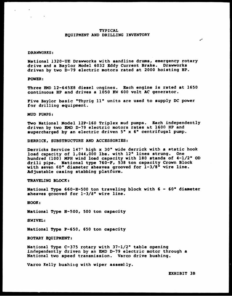
TYPICAL EQUIPMENT AND DRILLING INVENTORY
DRAWWORKS:
National 1320-UE Drawworks with sandline drums, emergency rotary dr ive and a Baylor Model 6032 Eddy Current Brake. Drawworks driven by two D-79 e l ec t r i c motors rated at 2000 hoisting HP.
POWER:
Three EMD 12-645E8 diesel engines. Each engine i s rated at 1650 continuous HP and drives a 1050 KW 600 volt AC generator.
F ive Baylor bas ic "Thyrig 11" units are used to supply DC power f o r dr i l l ing equipment.
MUD PUMPS:
Two National Model 12P-160 Triplex mud pumps. Each independently driven by two EMD D-79 e l e c t r i c motors rates bt 1600 HP and aupercharged by an e l e c t r i c driven 5" x 6" centrifugal pump.
DERRICK, SUBSTRUCTURE AND ACCESSORIES:
Derricks Service 147' high x 30" wide derrick with a s t a t i c hook load capacity of 1,044,000 lbs . with 12" lines strung. One hundred (100) MPH wind load capacity with 160 atands of 4-1/2" OD d r i l l pipe. National type 760-F, 538 ton capacity Crown Block with aeven 60" diameter sheaves grooved for 1-3/8" f i r e l i n e . Adjustable casing stabbing platform.
TRAVELING BLOCK:
National Type 660-H-500 ton traveling block with 6 - 60" diameter sheaves grooved for 1-3/3" wire l i n e .
BOOK:
National Type H-5 00, 500 ton capacity
SWIVEL:
National Type P-650, 650 ton capacity
ROTARY EQUIPMENT:
National Type C-375 rotary with 37-1/2" table opening independently driven by an EMD D-79 e l e c t r i c motor through a National two speed transmission. Varco drive bushing.
Varco Kelly bushing with wiper assembly.
EXHIBIT 3B

MUD MIXING:
Two 6" x 5" centrifugal mud mixing pumps. Each pump driven by a " 100 HP AC e l e c t r i c motor.
MUD SYSTEM:
Three 400 bbl. capacity liquid mud tanks and one 50 bbl. capacity slug tank. A l l active mud tanks equipped with Brandt Model MA-20 mud agitators. One S3-12 Pioneer Desander Unit, three 12" cones. One T16-4 Pioneer Desilter Unit, sixteen 4" cones. One Brandt Model DT Dual Shaker.
DRILL PIPE AND DRILL COLLARS:
9,800 ft. of 4-1/2" O.D. 16.60#/ft. Grade E, Range 2 D r i l l Pipe with 6-1/4" O.D. x 4-1/2" XH T.J.
5,000 f t . of 4-1/2" O.D, 20.00#/ft. Grade G, Range 2 D r i l l Pipe with 6-1/4" O.D. x 4-1/2" XH T.J.
24 - 7" O.D. d r i l l collars 30' long 12 - 8" d r i l l collars 30* long 1 - Kelly 5-1/4" HEX by 2-13/16" bore by 40' long with 4-1/2"
I.P. pin 1 (pair) B-J Type DB rotary tongs 3-1/2" to 11-1/4" range 2 - Byron-Jackson Type GG d r i l l pipe elevators for 4-1/2" O.D.
d r i l l pipe 1 - Varco DCS-L d r i l l collar s l i p s for 8" d r i l l c o l l a r 1 - 4-1/2" - 9-5/8" safety clamp Varco MP-R 2 - Varco 5" SDXL rotary s l i p s for 4-1/2" d r i l l pipe
BLOWOUT PREVENTERS:
One Cameron 21-1/4" - 2000 psi W.P. type "D"; One Cameron 13-5/8" - 5000 psi W.P. type "D"; One Cameron 13-5/8" - 10,000 psi W.P. type "U" single; One Cameron 13-5/8" - 10,000 psi W.P. type "U" double. One 10,000 psi W.P. Choke manifold with two adjustable chokes. Blowout preventers and choke manifold treated for H S service.
Blowout preventer control unit i s a Koomey Model ET25160-3&TM, 3000 psi W.P. accumulator system.
COMMUNICATION EQUIPMENT:
55 channel 25 watt VHF/PM Marine Tranaceiver 1 - 350 watt FM Transceiver 6 - 2 Channel VHF portable radios 1 - 100 watt FM Transceiver 1 - Inner Communication System with stations strategically
located
SPECIAL EQUIPMENT:
1. Varco PS-12 power s l i p s for 4-1/2" d r i l l pipe 2. Automatic D r i l l e r
EXHIBIT 3C

SPECIAL EQUIPMENT, Cont'd
3. Mud-Gas Separator 4. Dril ing Recorder 5. Dual »nud l i n e s complete with dual standpipes and 3" x 60" -
10,00 psi t e s t rotary hoses 6. BJ-Hughes cement unit driven by two dual Model 35 DC e l e c t r i c
motors 7. Varco Model 6500 Power Sub 8. Totco pit l e v e l and flowline indicator 9. Totco straight hole instrument 0 - 8 j.0. Totco type "E" WLA 75 weight indicator, DCT-25 tong torque
gauge, MG50 Pump pressure gauge, 379-35 Rotary RPM indicator, and 379-31 pump stroke indicators
11. Halliburton heavy duty diesel powered wire line unit with 14,000' of .092" line.
12. OMSCO 6-5/8" 15,000 psi test upper Kelly valve 13. TIW 10,000 psi test lower Kelly va.'ve 14. Gray inside BOP 15. Drilco E-Z torque hydraulic cathead 16. Fork l i f t truck for sack mud storage room 17. Two 400 amp. welding machines and oxygen-acetylene equipment 18. Overshots and Taper taps for contractor furnished d r i l l
string 19. One 15,000 psi test d r i l l pipe safety valve 20. Two Maxim RCF - 7.5 water d i s t i l l a t i o n units - 15,000 gallons
per day t o t a l 21. Baroid 821 Mud test Kit 22. Air tuggers for use on r i g floor and cellar deck area 23. One central a i r system consisting of two 583 CFM a i r
compressors, one cold s t a r t compressor and one water cooled after cooler
24. Diesel engine driven 2L0 KW emergency AC generator 25. Baylor Filteron sewage treatment plant 26. Drilco Degasser 27. Spinner-Hawk spinning Wrench 28. 2 -44 man Watercraft - Shatz covered L i f e Boats
EXHIBIT 3D

EXHIBIT No. 4
N
UNION OIL ANO GAS DIVISION 'NU. * OIL cn i iFOfttti* - TEXAS orrtHOfte DISTRICT
M A T A G O R D A 18. B>.K. 4 1 6 P R O I T E ' . T
O C S - G 7 2 0 1 W 0 . 9 6 '
M A T A G O R D A 18 .AREA OFFSHORE T E X A S
VICINITY MAP MTf rtLl m
M.I H. 9/S5

EXHIBIT #5A
KM* • ' • I M n M ' M n t i u u iooa n«TuMt


WATER-BASE LIGNOSULFONATE MUD SYSTEM COMPETITIVE MUD PRODUCTS REVISED 3/12/80
BAROID IMC MAGCOBAR MILCH EM DESCRIPTION
Baroid laco Bar
Weighting Material
Magcobar Mil-Bar Bari te (Barium Sulfate)
Aquagal Zeogel
Imco Gal Imco Br incga l
Imco Bast
C l a y ( V l s c o s l f i e r a )
Magcogel Sal t Gal
Super viebeatoa
Mil-Gal Salt Water Gel
I/oating Bantonita Attapulglte clay foi
•alt water nuds. Asbestos Materiel
Q-Broxin
Car bono x Sodium Chromate
IMCO VC-10 Imco L i g Sodium Chromate
Thinners
Spersene Tan- ithin Sodium Chromate
Unlcal Llgco Sodium Chromate
Perrochroae Lignosulfonate
Chrome Llgnosulfonste Processed Lignite Sodium Chromete
(Chrom Additive for CLS Products)
Cellex Imco-CMC
Fluid Loss Control Agents
Magco-CMC MilCham CMC Sodium Carboxymethyl-cellulose
Lime Caust ic ScJa
A l k a l i n i t y , pH Control Additives
lime Caustic Soda
Lime Caust ic Soda
Lima Caustic Sods
Bydratad Lima Sodium Bydroxlde
S.A.P.P.
Bicarbonate of Soda
Imco Fhoa (SAPP)
Bicarbonate of Soda
Calcium Removers
S.A.P.P.
Bicarbonate of Soda
8.A.P.P.
Bicarbonate of Soda
Sodium Acid Pyrophosphate
Sodium Bicarbonate
Aluminum Stearata
Aluminum Stearata
Pefoamer
Aluminum Stearata
Aluminum Stearata
Aluminum Stearata
Micatex Mall Hut
Imco Mica Imco Plug
Lost C i r c u l a t i o n Materials
Magco Mica But Plug
Mil Mica Mil Plug
Mica Flakes (Grsded) Ground Walnut Bu l l s
(Graded)
TRADE MAME
CLS Drispac
COMPABY
MIKgLLANfOUB PPPPgCTt
Louisiana Mud D r i l l i n g S p e c i a l t i e s , I n c .
DESCRIPTION
Chrome Lignosulfonate - Thinner Polyenlonic Cellulose - Fluid Loss Control
EXHIBIT 6
.7
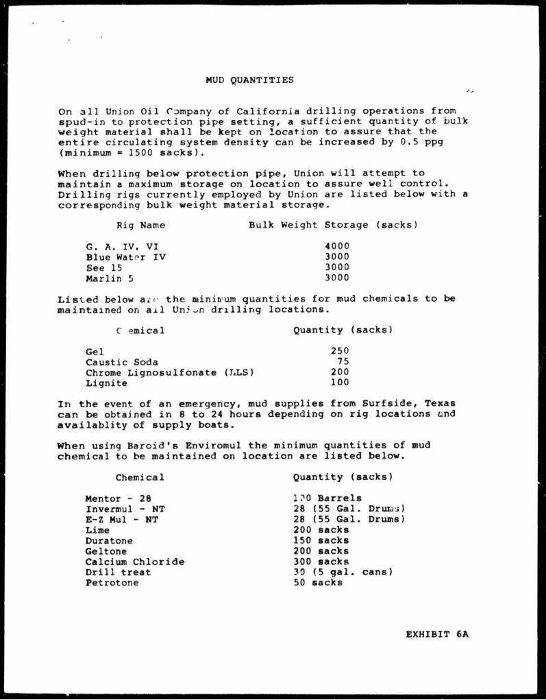
MUD QUANTITIES
On a l l Union O i l Company of C a l i f o r n i a d r i l l i n g operations from s p u d - i n to p r o t e c t i o n pipe s e t t i n g , a s u f f i c i e n t quantity of bulk weight material s h a l l be kept on locat ion to assure that the e n t i r e c i r c u l a t i n g system dens i ty can be increased by 0.5 ppg (minimum = 1500 s a c k s ) .
When d r i l l i n g below protect ion p i p e . Union w i l l attempt to m a i n t a i n a maximum storage on l o c a t i o n to assure we l l c o n t r o l . D r i l l i n g r igs c u r r e n t l y employed by Union are l i s t e d below with a corresponding bulk weight m a t e r i a l storage.
Rig Name Bulk Weight Storage ( sacks)
G. A. IV. VI 4000 Blue Waf»r IV 3000 See 15 3000 Marlin 5 3000
L i s t e d below ax« the minimum quantities for mud chemicals to be maintained on a i l Uni ~»n d r i l l i n g locations.
C emical Quantity (sacks)
Gel 250 Caustic Soda 75 Chrome Lignosulfonate (LLS) 200 Lignite 100
In the event of an emergency, mud supplies from Surfside, Texas can be obtained i n 8 to 24 hours depending on ri g locations &nd ava i l a b l i t y of supply boats.
When using Baroid's Enviromul the minimum quantities of mud chemical to be maintained on location are l i s t e d below.
Chemical Quantity (sacks)
Mentor - 28 100 Barrels Invermul - NT 28 (55 Gal. Druiaj) E-Z Mul - NT 28 (55 Gal. Drums) Lime 200 sacks Duratone 150 sacks Geltone 200 sacks Calcium Chloride 300 sacks D r i l l treat 30 (5 gal. cans) Petrotone 50 sacks
EXHIBIT 6A

AIR QUALITY STATEMENT
The plan of o p e r a t i o n s f o r t he d r i l l i n g o f the e x p l o r a t o r y w e l l s f o r OCS-G-7201, B lock 618, Matagorda I s l a n d Area i s set ou t i n t h e preceding pages .
I t i s expected t o t ake a p p r o x i m a t e l y 80 days t o d r i l l and complete the w e l l . The r i g t o be used t o d r i l l these w e l l s w i l l be a t y p i c a l j a c k - u p r i g . The normal f u e l consumption per day f o r t h i s r i g i s a p p r o x i m a t e l y 1800 g a l l o n s o f d i e s e l . The onshore support base f o r t h i s a c t i v i t y w i l l be Union O i l Company o f C a l i f o r n i a shore base l o c a t e d a t S u r f s i d e , Texas. A l l t r a n s p o r t a t i o n , boa t s and h e l i c o p t e r s , w i l l be handled f rom t h i s b a s e .
A i r emission c a l c u l a t i o n s a re based on the a fo remen t ioned d r i l l i n g t ime f r ame and data f r o m " C o m p i l a t i o n o f A i r P o l l u t a n t Emiss ion F a c t o r s " , t h i r d e d i t i o n AP-42, EPA, Tables 3 . 3 . 3 - 1 and 3 . 2 . 1 - 3 . Any a d d i t i o n a l work r e q u i r e d w i l l be m i n i m a l and r e s u l t i n a i r emissions w e l l below t n e exemption l e v e l .
EXHIBIT 7

LEASE/AREA: OCS-G-7201/MAT. I S L . BLOCK: 618 PLATFORM: JACK-UP
EXEMPTION CALCULATIONS
3400 (D
33.3 D
2/3, f o r carbon monoxide
f o r s u l f u r dioxide, nitrogen oxides, t o t a l suspended p a r t i c u l a t e s , and v o l a t i l e organic compounds
D = 28.8 Statute Miles (152 ,064 f t . )
E - 31949 CO
E = 959 S0 2, NOx, TSP, and VOC
POLLUTANTS "E" (T/YR )
1986 HIGHEST YEAR PROJECTED EMISSIONS
(T/YR.) EXEMPT
(YES OR NO)
so2 959 2.86 YES
NOx 959 42.51 YES
CO 31949 9.33 YES
TSP 959 3.08 YES
VOC 959 3.49 YES
E = The emission exemption amount expressed i n tons per year.
D • The distance of the f a c i l i t y from the closest onshore area of a state expressed i n st a t u t e miles.
EXHIBIT 7A

LEASE/AREA: OCS-G-7201/MAT. ISL. BLOCK: 618 PLATFORM: JACK-UP-
PROJECTED EMISSIONS FROM EACH SOURCE
BY AIR POLLUTANT FOR 1986 (Year)
SOURCE SO 2
AIR NOx
POLLUTANT CO
(T/YR.) TSP VOC
D r i l l i n g Rig 4493 67536 14688 4824 5400
Cargo Boat 10 150 33 11 12
Crew Boat 10 150 33 11 12
Helicopter 58 182 182 80 166
Sub Total 4571 68016 14936 4926 5590
Miscellaneous 25% of Sub To t a l 1143 17004 3734 1231 1398
TOTAL - Pounds 5714 85022 18670 6157 6988
T o t a l from F a c i l i t y I n Tons Per Year 2.86 42.51 9.33 3.08 3.49
EXHIBIT 7B

LEASE/AREA: OCS-G-7201/MAT. ISL. BLOCK: 618 TYPE: JACK-UP
FREQUENCY DISTRIBUTION OF TOTAL EMISSIONS
S0 2, NOx, CO, TSP, VOC FOR 1986
Po l l u t a n t ( s ) Year(s)
POLLUTANT
SO 2
NOx
CO
TSP
VOC
YEAR
1986
1986
1986
1986
1986
EMISSION RATES POUNDS/DAY DAYS/YEAR
71.4
1062.7
233.4
76.9
87.3
80
80
80
80
80
REMARKS:
EXHIBIT

PROJECTED AIR EMISSION FOR MATAGORDA ISLAND BLOCK 618
EMISSION SOURCE RUNNING TIME/DAY
TAKEOFFS & LANDINGS/DAY
FUEL CONS, GALS./DAY
EMISSION FACTORS 1/1000 GALS.
Calculations f o r 80 Day ^ r i l l i n g Phase _f°2 NOx CO TSP VOC
D r i l l i n g Rig 24 hrs. 1800 31.2 469 102 33.5 37.5
Cargo Boat ( I n Berth) 2 hrs. 4 31.2 469 102 33.5 37.5
Crew E^at (In Berth) 2 hrs. 4 31.2 469 102 33.5 37.5
Helicopter 4 .18 .57 .57 .25 .52
Projected Emission 8C Day Proj. i n # Total i n Pounds
SO 2 NOx CO TSP VOC SO 2 NOx CO TSP VOC
4493 67536 14688 4824 5400 4571 68018 14936 4926 5590
10 150 33 11 12
10 150 33 11 12
58 182 182 80 166
Projected emissions are based on Edition AP-42. EPA, 1977, Table 3
data from "Compilation .3.3-1 and Table 3.2.1-
of A i r -3
Pollutant Emission Factors", 3rd
EXHIBIT 7D