SIMULINK modeling of a marine autopilot for TSSE ship designs

XV-1
XV. TSSE EXPEDITIONARY WARFARE SHIP DESIGN
A. INTRODUCTION
The purpose of the TSSE capstone design project was to examine the concepts associated
with Sea Basing or Sea Based Logistics in support of ExWar in the context of OMFTS and
STOM concepts of operation. The product from this examination was the creation of a ship
design to enable effective Sea Basing operations.
The objectives for this project included maximizing the use of the material learned in
previous TSSE courses. The project required the TSSE team to define the concept of
employment needed to meet a broadly-defined need, as well as learning first-hand the ship-
impact of requirements, cost and performance tradeoffs within technical and acquisition
constraints. Through this process, the students became familiar with the process of evaluating a
military need to determine how best to meet it, and obtain the experience in the process of
translating broad military requirements to mission-based ship requirements and to specific design
tasks resulting from those requirements. In addition, the project also stressed technical
teamwork in an interdisciplinary design effort where the quality of the product is greatly affected
by team dynamics. Lastly, the TSSE team practiced internalizing the systems approach to a
naval ship as a single engineering system satisfying mission requirements, and exploring
innovative ideas which may prove useful to those working on similar projects, both inside and
outside NPS. Figure XV-1 illustrates the TSSE design roadmap.
1. Phase I
In phase I the team focused on requirements analysis. The goal was to review and
understand the requirements from the Systems Engineering and Analysis (SEA) team for Sea
Basing within expeditionary warfare. Further, the team had to analyze the nature of the
requirements and anticipated solutions for the MPF(F), LHA(R), and Large Medium Speed Roll-
on-roll-off (LMSR) ships. Through this analysis, the TSSE team determined if the ExWar Sea
Basing requirements could be fully met by a single ship design (with variants permitted) that
could be employed in lieu of the separate ship types. This would require us to consider such

XV-2
things as: combat systems capabilities; interfaces with transfer assets; survivability levels
needed; nature of manning (civilian or Navy crews or some mix); etc. The team was expected to
interface with the SEA team on a regular basis for clarification of their initial requirements
document and for its updates, as appropriate, and to determine that the approach appeared to be
on track to meeting the needs SEA had documented. The TSSE team would have to answer
questions such as:
• Can a single design with variants meet the need?
• How will the variants vary?
• Which variant would be proposed and treated as the primary subject of further
design?
SynthesisFeasibilityStudies
TechnologyExploration
Analysis ofAlternatives
RequirementsAnalysis
Conceptual
Design
Review IRD
3 Ship Study
MPF/LMSR
LHA/MPF
Single Ship
ConceptExploration
Phase I Phase II Phase III
Concept
Decision
Point
Figure XV-1: TSSE Design Roadmap

XV-3
2. Phase II
In phase II the team explored concepts for meeting the basic design. By the end of the
phase, the team reconciled in more detail the requirements for the basic ship and for its variants.
3. Phase III
During phase III the team performed a more complete design of the basic concept and
variants resulting from Phase II.
B. REQUIREMENTS ANALISYS
Requirements analysis was one of the most important phases in the TSSE project design.
Requirements analysis was important because it helped the team to understand the problem. By
analyzing the requirements, the team defined and bounded the problem. In this particular case,
the TSSE team needed to understand the mission of the system; by understanding the mission,
the team becomes aware of the required capabilities needed to accomplish the mission. Knowing
the required capabilities, the team could explore possible systems alternatives that would
effectively perform the required capabilities. Requirements analysis also helped the team to
understand the interfaces between systems, and how they affect each other. By understanding
the interfaces, the team could make trade-off decisions among systems capabilities and
resources. This trade-off allowed the team to arrived to a well-balanced and optimum design.
The TSSE requirements analysis approach was very similar to the strategy taken by the
SEA team in the system of systems study of ExWar. The strategy derived the design
requirements through both Top Down and Bottom Up analyses. Figure XV-2 illustrates the
TSSE requirements generation process.

XV-4
Top Down Analysis
Design Requirements
Bottom Up Analysis
SEA IRDSea BaseCONOPS
LHA(R) MPF(F) LMSR
MEBDefinition
Figure XV-2: TSSE Requirements Generation Process The Top Down analysis concentrated on understanding the SEA Initial Requirements
Document (IRD), clarifying issues with the SEA team by an iterative process, and generating a
requirements list. The second portion of the Top Down analysis studied the CONOPS for Sea
Basing and what capabilities are required to do Sea Basing. The analysis also required us to
understand the MEB, what composes it, and what are its requirements.
The Bottom Up portion of the requirements analysis focused on the LHA(R), MPF(F),
and LMSR CONOPS, and current platforms in the Naval Expeditionary architecture. A list of
requirements was generated and merged in the requirements from the Top Down analysis into
master Required Operational Capabilities (ROC) document.
C. SEA INITIAL REQUIREMENTS DOCUMENT (IRD) ANALYSIS
The SEA IRD was the governing document in the analysis and development of the
requirements for the TSSE concept design. The IRD identified Sea Base capability gaps through
XV-5
the Systems Engineering Top Down analysis. At this stage of the design process, it was crucia l to
the TSSE team to have a complete understanding of the IRD. Accordingly, the team commenced
a detailed review of the requirements stated in the SEA IRD. Initially, two very important issues
were quickly identified. The first issue was that the IRD did not define a MEB. The second
issue dealt with the numerous documents that dealt with the Sea Base concept, each one of them
having a different interpretation of the concept. The exploration of these two issues lead to the
conception of a base line for the Notional MEB, and a Sea Base Concept of Operations, its
required capabilities, and recommendations as to the type and number of ships required to meet
these requirements.
1. The Marine Expeditionary Brigade (MEB)
a. Command Element (CE)
The MEB command element provides command and control for the elements of the
MEB. When missions are assigned, the notional MEB command element is tailored with
required support to accomplish the mission. Detachments are assigned as necessary to support
subordinate elements. The MEB Command Element is fully capable of executing all of the staff
functions of a Marine Air-ground Task Force (MAGTF) (administration and personnel,
intelligence, operations and training, logistics, plans, communications and information systems,
Comptroller, and COMSEC).
b. Ground Combat Element (GCE)
The ground combat element (GCE) is normally formed around a reinforced infantry
regiment. The GCE can be composed of two to five battalion sized maneuver elements (infantry,
tanks, LAR) with a regimental headquarters, plus artillery, Assault Amphibian Bn,
reconnaissance, TOWs, and engineers.
c. Aviation Combat Element (ACE)

XV-6
The aviation combat element (ACE) is a composite Marine Aircraft Group (MAG) task-
organized for the assigned mission. It usually includes both helicopters and fixed wing aircraft,
and elements from the Marine wing support group and the Marine air control group. The MAG
has more varied aviation capabilities than those of the aviation element of a MEU. The most
significant difference is the ability to command and control aviation with the Marine Air
Command and Control System. The MAG is the smallest aviation unit designed for independent
operations with no outside assistance except access to a source of supply. Each MAG is task-
organized for the assigned mission and facilities from which it will operate. The ACE
headquarters will be an organization built upon an augmented MAG headquarters or provided
from other MAW assets.
d. Combat Service Support Element (CSSE)
The brigade service support group (BSSG) is task-organized to provide combat service
support beyond the capability of the supported air and ground elements. It is structured from
personnel and equipment of the force service support group. The Brigade Service Support Group
provides the nucleus of the Landing Force Support Party and, with appropriate attachments from
the GCE and ACE, has responsibility for the landing force support function when the landing
force shore party group is activated.
e. Capabilities
• Inherently expeditionary combined arms force.
• Robust and scalable Command and Control capability.
• A full range operational capability from forcible entry to humanitarian assistance.
• Task organized for mission accomplishment.
• Capable of rapid deployment and employment via: amphibious shipping, strategic
air/sealift, or any combination.
• Sustainable.
• Increased command and control and significantly expanded battle space, functions, and
capabilities.
XV-7
• Aviation element is capable of all aviation functions: Offensive Air Support, Anti-air
Warfare, Assault Support, Air Reconnaissance Electronic Warfare, Control of Aircraft
and Missiles, Exercise Command and Control of aircraft and airspace.
• Full spectrum of Expeditionary Combat Service Support: Supply, Maintenance,
Transportation, General Engineering, Health Services, Services, and Messing.
2. Defining the MEB
The flexible nature of the Marine Corps made it difficult to establish a MEB baseline. In
order to proceed with the design of the ship, the team had to establish the precise number of
people, equipment, and supplies required to deploy a MEB. After careful considerations, the
team proceeded to establish a notional baseline for a MEB based on the MPF MEB. Figure XV-
3 illustrates the organizational diagram for the MEB. Tables XV-1, 2, 3 describe the major
equipment, number of personnel, provisions, ordnance, and fuel required to sustain a MEB for 30
days.

XV-8
Figure XV-3: Marine Expeditionary Brigade
(Source: Marine Expeditionary Brigade, 2002)

XV-9
Support Equipment
Major Weapons
Aviation Element
Total Personnel
Armed HMMWV 57 LAV AT 4 HLA 36 18,000
LVS Power Unit 109 LAV 25 14 AH-1Z 24
LVS Wrecker 4 LAV LOG 3 UH-1Y 24
LVS Trailer 53 LAV RECOV 3 MV-22 96
5 Ton 282 AAVC7 9 JSF 36
P-19 8 8 AAVR7 4
HMMWV 473 AAVP7 96
MRC-110 65 M1A1 58
MRC-138 60 HMMWV (TOW) 72
MRC-142 21 M198 Howitzers 30
M970 Refueler 26
Table XV-1: Equipment and Personnel for Conceptual MEB
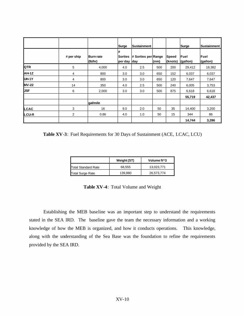
3. Sustainment
Perhaps even more difficult than defining what constitutes a MEB was to define its
sustainment requirements. In this instance, the team decided to use CDR Kennedy’s (Kennedy
2002) thesis sustainment data to provide with guidance as to the amount of provisions, and
ordnance, required by the Sea Base and the MEB ashore. Table XV-2, summarizes the amount
of provisions and ordnance required by the Sea Base and MEB ashore. With respect to the
amount of fuel required to sustain the MEB ashore, the team decided to utilize the data provided
by the Center for Naval Analysis study titled Fuel Requirements and Alternative Distribution
Approaches in an Expeditionary Environment (Center for Naval Analysis, 2001), Table XV-3,
provides the amount of fuel in gallons required by the GCE, CSSE and the conceptual ACE.
Table XV-4 presents the total weight and volume required including equipment, fuel, ordnance,
and provision for 30 day at a surge rate.
Commodity Days Std. Rate(tons/day) Weight Volume (ft^3) Surge
Rate(tons/day)Weight Volume (ft^3)
Provisions 30 95 2850 304000 95 2850 304000
Ordnance 30 550 16500 880000 687.5 20625 1100000
Total 19350 1184000 23475 1404000
Table XV-2: Daily Sustainment Rates, Weight, and Volume for a MEB
(Source: Kennedy, 2002)
XV-10
Surge Sustainment Surge Sustainment
# per ship Burn rate
(lb/hr)
# Sorties per day
# Sorties per day
Range (nm)
Speed (knots)
Fuel (gallon)
Fuel (gallon)
QTR 5 4,000 4.0 2.5 500 200 29,412 18,382
AH-1Z 4 800 3.0 3.0 650 152 6,037 6,037
UH-1Y 4 800 3.0 3.0 650 120 7,647 7,647
MV-22 14 350 4.0 2.5 500 240 6,005 3,753
JSF 6 2,000 3.0 3.0 500 875 6,618 6,618
55,719 42,437
gal/mile
LCAC 3 16 9.0 2.0 50 35 14,400 3,200
LCU-R 2 0.86 4.0 1.0 50 15 344 86
14,744 3,286
Table XV-3: Fuel Requirements for 30 Days of Sustainment (ACE, LCAC, LCU)
Weight (ST) Volume ft^3
Total Standard Rate 68,555 13,023,771
Total Surge Rate 139,880 26,573,774
Table XV-4: Total Volume and Weight
Establishing the MEB baseline was an important step to understand the requirements
stated in the SEA IRD. The baseline gave the team the necessary information and a working
knowledge of how the MEB is organized, and how it conducts operations. This knowledge,
along with the understanding of the Sea Base was the foundation to refine the requirements
provided by the SEA IRD.

XV-11
4. The Sea Base
a. Understanding the Sea Base Concept
Understanding the Sea Base concept was a challenging task for the team. First, because
until now, there was not an established architecture for the Sea Base, how it should operate, or
how it should be employed. Second, as mentioned earlier, there are a multitude of documents
that try to define the Sea Base. These concepts range from creating a Sea Base with current
systems, to the Mobile Offshore Base concept, which describes the Sea Base a series of massive
interconnected platforms that could land heavy transport aircraft.
The team approached the Sea Base study as one that explored the different capabilities
that a Sea Base should possess. With that philosophy in mind, the team proceeded to review as
many documents as possible which dealt with the Sea Base concept, merged these capabilities
with the requirements presented in the SEA IRD, and generated a common list of required
capabilities for the Sea Base.
b. Operating Area/Environment
• On station – 25-250 NM from the beach.
• Threshold Sea State 3 (3.5-4 ft) for all missions.
• Transatlantic Capability – include supporting MEB en route.
• Escorts will be part of force structure in/en route to the Objective Area – SEA
defined the numbers/type/distance requirements for the Expeditionary Strike
Group (ESG) escorts.
• Must have ability to operate :
o Independently in a low threat environment
o As part of a larger Task Force (CVBG) with air cover from the Task
Force in medium to high threat environment.
c. Logistics/Stowage
• System must provide C2 of logistics operations w/in the Sea Base and ashore.
XV-12
• System must provide increased aviation ordnance stowage and handling
facilities.
• TSSE must develop clear understanding of storage capacity required for
fuel/ordnance/spares of both the ship and MEB.
• TSSE must develop storage plan for current and future aircraft and surface
assault assets of afloat MEB as well as Long Range Heavy Lift Aero Design,
Unmanned Underwater Vehicles (UUV), Unmanned Surface Vehicles (USV),
and UAVs.
• Carry non-standard Special Forces ordnance.
d. Speed Requirements
• General - System must be capable of reaching theater at speeds no less than
current platforms but preferably at cruise speed of 25 or above.
• Must meet requirements to allow for maneuver warfare from the sea in
accordance with OMFTS.
• TSSE will have to specify desired operating speed for transatlantic mission
with or without MEB embarked.
e. Sustainability
• Must have throughput ability for indefinite sustainability
• Must be able to sustained MEB for a min. 30 days
• Must be able to be replenished by legacy, future Commander Landing Force
platforms, and commercial shipping.
f. Maintenance/Repair
• Must be able to conduct and facilitate Intermediate Level Maintenance to support GCE, ACE, CSSE equipment, and other units of the ESG.
g. Distribution & Interfaces

XV-13
• Have multiple inherent capabilities to distribute logistics support to the
maneuver units positioned up to 200 NM in shore. - not just rely on air
platforms.
• Have "just/right time" distribution capability.
• Must be able to interface with legacy systems.
i. MEB Requirements
• Must be able to sustain a MEB ashore for a minimum of 30 days with
throughput ability for indefinite sustainment.
• Throughput sustainability conducted via float-in and fly- in concept
• MEB size expected to be ~ 5,000 (GCE) Marines and support
personnel/equipment
j. Medical
• Support natural disasters, noncombatant evacuation operations, Militaqry
Operations other than War (MOOTW), and human suffering to include patient
regulation, transport/evacuation, receipt, and stabilization.
• Treatment facilities for critical patients.
• Decompression facilities for Explosive Ordnance Disposal (EOD)
k. Habitability
• Ship’s Crew - Mixed Gender
• MEB Personnel (GCE, CSSE, and ACE) approximately 15,000
• Support Special Forces Personnel
• Reduced Manning Employed
• Crew Comfort and Quality of Life must be incorporated
• Must support training areas for crew and embarked units

XV-14
l. Survivability
• System must have Chemical, Biological, and Radiological protection.
• System must be able to defend itself against leakers (Anti-ship Cruise
Missiles) from the escort forces.
• TSSE will determine stealth features.
m. Loading/Unloading Requirements
• Must be capable of performing loading/unloading in port and at sea.
• TSSE must determine rates for operations in order to fully support rapid
optempo requirement for ExWar mission.
• Selective offload capability imperative.
• System must support reconstitution and redeployment of Ex War forces.
• Must be compatible with future fleet oilers and supply ships.
• Vertical Replenishment capabilities that fully support logistics needs of
ExWar forces.
• Must be capable of receiving casualties from air/waterborne craft.
n. Warfare Capabilities
• Self-Defense Capability to include the following warfare areas:
o Air Warfare (AW)– detect, ID, track, and defeat leakers.
o Surface Warfare (SUW) - detect, ID, track and defeat multiple
small high-speed surface craft.
o Undersea Warfare (USW) – support antisubmarine Warfare
(ASW) and Mine Countermeasures (MCM) ops to include
helicopters, Unmanned Underwater Vehicles (UUVs), and Mine
Warfare (MIW) assets.
o Strike Warfare (STR) – coordinate, task and support strike
missions.

XV-15
• Offensive capability
o Capability to coordinate, undertake and support of Strike Missions:
o Provide initial operational fires to support the MEB (minimize
footprint).
o Support the Marine Corps Theater Air Missile Defense.
o. Replenishment
• System must act as an integrated OTH floating distribution center and
workshop.
• Must be capable of repackaging and delivery of units to the Ex War force
afloat or ashore.
• Spaces must allow for ease of reconfiguration (modularity) to support multi-
mission functions of ExWar force.
• TSSE must determine how the interface with AC, small boats, and other cargo
vehicles will flow.
p. Air Operations
• Support Tactical Recovery of Aircraft and Personnel missions.
• Accommodate MV-22, STOVL Joint Strike Force and all current MEB air
assets.
• Ability to operate and launch UAVs/UCAVs.
q. C4ISR
• Defense in Depth with sufficient physical protection, firewalls, and
redundancy for information and communication networks.
• Communications and computers must be, network centric, and compatible
with other service, and coalition assets (interoperable).
• Theater to CONUS connection (Reach back) for ISR.
r. Modularity
XV-16
• Incorporate modularity in design of selected compartment(s) to allow for
reconfiguration depending on mission needs.
o SOF operations, non Electronic Warfare operations, strike mission
o Carrying less cargo but having more Vertical Launch System
modules to support strike missions.
D. REQUIREMENTS GENERATION FROM LHA (R), MPF(F), AND LMSR OPERATIONAL CONCEPTS
The next step for the TSSE design team was to analyze the LHA (R), MPF (F), and
LMSR CONOPS, and current LHA/D capabilities. This analysis took ensured that no
capabilities were left without being analyzed. In addition, as new systems are designed to
replace old ones, their CONOPS will incorporate new capabilities which are necessary to support
future CONOPS such as Sea Basing and STOM. The analysis of these CONOPS allowed us to
revisit the Sea Basing concept, compare its required capabilities with the capabilities already
compiled from the SEA IRD analysis, and consolidate them into a master requirements
document. Capabilities for both conceptual and current platforms were consolidated into
mission areas.
a. Air Warfare
The ship must be able to defend against advance Anti-Ship Cruise Missiles. It must be
able to support and leverage joint integrated air defense systems to provide support throughout
the Objective Area, but especially support of the Marine Corps Theater Air Missile Defense.
The ship should have decoy systems, which at a minimum have the capabilities and
characteristics of systems installed in current platforms. The Electronic Warfare suite should be
able to facilitate “soft kill” of air threats. The ship will not be expected to be a long-range air
defense platform.
b. Amphibious Warfare

XV-17
The ship must be able to transport 1700 troops. Current platforms have a 300 ft well
deck that supports 3 Landing Craft Air Cushion (LCAC), or 2 Landing Craft Utility (LCU),
AAV, AAAV, and future LCU and LCAC replacements. Amphibious operations will be
conducted OTH at least 25 NM from shore. Once the initial assault takes place, ships can move
further out to sea to commence the sustainment phase. Current Marine Corps sustainment policy
requires the ships to support a MEU for 15 days, a MEB for 30 days, or a MEF for 60 days. The
ship must be able to transport and support the landing force with maintenance, supply, medical
and fire support coordination as part of a Sea Base. As part of the Command and Control
architecture, the ship must provide airspace and surface management throughout the objective
area with high-density airspace control zone. The ship must be able to support and operate with
the MV-22, AAAV, STOVL Joint Strike Force, SH-60R, and UAV with at least 42 multiple
points for aircraft spotting. The ship must be able to conduct both rotary and fixed wing flight
operations simultaneously. In order to support the Marine Corps Advanced Fire Concept, the
ship will conduct or coordinate the Sea Base assets to conduct fire support missions, around the
clock
The ship must be able to employ torpedo decoy systems, and be able to support sustained
littoral campaigns in a coastal water submarine environment.
c. Command Control Communications
The ship will be able to support the Expeditionary Sensor Grid (ESG). It must also be
able to receive information from various UAV platforms, with full tactical control systems. The
ship will provide tactical, secure voice or data communications, plan, coordinate, and control
implementation of Operations Security measures. The ship must be able to communicate with
the embassies, theatre or JTF commander, and Special Operation Forces working in conjunction
with expeditionary forces. In addition, the ship must be able to support communications for
embarked staff. Communications systems must be compatible with tactical command and the
control architecture of the Amphibious Task Force. The C2 architecture must be network centric
warfare based to allow Joint C4I interoperability.
d. Command Control Warfare

XV-18
The ship’s Electronic Warfare (EW) suite must be able to facilitate “soft kill” of air
threats, and complicate the enemy’s targeting process.
e. Fleet Support Operations
The ship must have at a minimum a 578-bed hospital/morgue, 6 operating rooms, provide
medical, and dental facilities to support Sea Base personnel. The ship will perform intermediate
level aircraft maintenance, and provide support for organizational level preventive and corrective
maintenance. The ship will support forces ashore for supply maintenance, distribution, and
salvage engineering.
f. Intelligence
The ship must be able to receive information from various UAV platforms, with full
tactical control systems. The ship must be able to monitor electronic emissions from shore and
from other ships.
g. Logistics
In order to transport the large number of vehicles and stores, the ship must have at least
25,400 square feet of vehicle storage volume, and 125,000 cubic feet of cargo storage volume
(3087 cubic meters of dry cargo space). The ship will carry at least 1232 tons of aviation fuel.
The ship must provide indefinite sustainment for logistic support, and be able to integrate
operations with Joint in theater logistic agencies and transition from Sea Based logistics support
system to a shore based system. The ship must be able to receive and process 20 ft standard
containers and other packaging configurations from intra or inter theater distribution sources,
segregate contents, and assemble components into unit level loads for distribution. The ship will
be able of operating independently to provide strategic sealift capacity in support of rapid
deployment of heavy mechanized Army and Marine Corps combat units on a worldwide basis.
In additions, the ship must provide ship configuration suitable for container loading and

XV-19
discharging by a shore facility (non-self sustaining container ship), and load, stow, transport, and
discharge outsized and oversized military equipment. The ship will fulfill the Strategic Sealift
mission by transporting common-user cargo and military vehicles, including tanks and
helicopters, pre-positioned overseas or surged from the United States to support exercises and
real–world contingencies. The Ship will be equipped with self-sufficient Roll-on/Roll-off and/or
Lift–on/Lift–off facilities for rapid loading, deployment, and offloading. The ship will have
systems compatible with the Standard Tensioned Replenishment Alongside Method for the
transfer of ammunition, cargo, missiles, and personnel. The ship will provide small boat services
for transfer of personnel, cargo, weapons, provisions and supplies. In addition, the ship must
provide a safe and secure small arms storage area, and provide for proper storage, handling, use,
and transfer of hazardous materials.
h. Mine Interdiction Warfare
In order to support MIW operations, the ship must have facilities and capabilities fully
compatible with operating and supporting mine sweeping assets to include the “flyaway” version
of the Remote Mine-hunting System, SH-60R with Airborne Mine Countermeasures kits (hunt
and kill), and the ability to embark Mine Countermeasures staff. The ship must possess self-
protective measures to manipulate its signature, harden the platform for detonation effects, and
detect, avoid and neutralize mines.
i. Mobility
The ship’s speed must be comparable to other Navy surface ships in the timeframe of
2015 and beyond (25-27 knots or more). The design will not be restricted in size by the Panama
Canal. It should be able to operate in at least sea-state 3, with a range of 10,000 NM. The ship
must facilitate theater reconstitution and redeployment of forces without a requirement for
extensive materia l, maintenance, or replenishment support at a strategic sustainment base.
The ship must counter and control Chemical, Biological, and Radiological
contaminants/agents, and provide damage control security and surveillance. The ship must be
able to get underway, moor, anchor, and sortie with duty section in a safe manner, provide life
boat/raft capacity in accordance with unit’s allowance, and moor alongside oceangoing fleet tug

XV-20
shipping or docks.
j. Non Combatant Operations
The ship must be able to operate with other military services, government agencies and
multinational forces, operating with aircraft, displacement and non-displacement craft, and
command/control systems to coordinate these operations. The ship will require a robust multi-
media capability that will be able to produce leaflets, posters, and schedules. The ship will
require areas for medical and dental care, feeding, and berthing of evacuees. The ship will
support or conduct helicopter/boat evacuation of noncombatant personnel as directed by higher
authority, and provide for embarkation, identification, processing of evacuees.
k. Naval Special Warfare (SPECOPS)
The ship must be able to support Special Warfare personnel, equipment, and special
ordnance.
l. General
The ship must support varying ratios of male and female crew, troops, and staff. It must
be designed to permit rapid reconfiguration to respond to changing threats and missions. The
ship must allow embarked personnel to conduct and prepare unrelated missions and be able to
successfully complete them.
The ship must be able to provide facilities and personnel for material, mail, and passenger
handling. It must provide stowage and berthing spaces for equipment and personnel during
transit. The ship must monitor the health and well being of the crew to ensure that habitability is
consistent with approved procedures and standards. The ship must be able to safely operate and
execute all assign missions in a manner that is consistent with naval directives pertaining to the
prevention of environment pollution.
3. Merging SEA IRD, LHA(R), MPF(F), and LMSR requirements
XV-21
Up to this point in the design process, the TSSE team had analyzed the SEA IRD, studied
current MEB architecture, analyzed Sea Basing, and produced a list of required capabilities. The
team had also studied concepts of operation for LHA(R), MPF(F), and LMSR and generated
their requirements. All these requirements were fused into a master Required Operational
Capabilities (ROC) document. This document eliminated redundancies, consolidated all of the
previous requirements, and became the baseline for the TSSE design. The master ROC is listed
in appendix 16-1 of this chapter.
E. FEASIBILITY STUDIES
After establishing the requirements baseline, it was necessary to identify possible systems
solutions which could meet those requirements; and then evaluate the most likely concepts in
terms of performance, effectiveness, maintenance, logistical support, concept of operations, and
potential cost. Recommendations were made from all the feasible alternatives, and advantages
and disadvantages were identified for the selected courses of action.
The starting point for the feasibility study was to make a determination on the number
and types of ships needed to fulfill the requirements. After determining these two issues, the
study focused specifically on refining the selected alternatives. Characteristics such as ship type,
displacement, length and beams were estimated for each of the alternatives. The final three
alternatives were as follow:
a. LHA/MPF With LMSR Variant
b. MPF/LMSR With LHA Variant
c. Single Ship
1. Number of Ships
Once a MEB baseline and an estimate of the weight and volume requirement were
established, it was necessary to approximate the number of ships and their displacements. Tables
XV-5 and XV-6 present the 3 and 6 ships options respectively. Taking table XV-5 as an
example, the total payload requirement is 140,000 short tons (ST). That figure divided by 3

XV-22
ships resulted in a payload per ship of approximately 46,667 ST. The next five columns
represent the payload to displacement ratio. In a warship such as a frigate or destroyer, the
payload is approximately 25% of the ship’s displacement. On the other side of the spectrum in a
container ship, where the payload is 80% of the ship’s displacement. The same is applicable for
table XV-6, except that in this case, the total payload was divided among 6 ships. Based on
these two tables, the team decided that the 6-ship option was the best because the displacement
per ship was more feasible. Furthermore, the team also estimated that the displacement would
likely fall between 35% and 60% of the ship’s payload. These conclusions were consistent with
current LHA/D class of amphibious assault ships characteristics.
Displacement & Volume per
Ship 3 SHIPS
Warship Ratio Somewhere in between Container Ship Ratio
Payload Total Payload Payload per Ship 25% 35% 50% 60% 80%
Weight (ST) 140,000 46,667 186,667 133,333 93,333 77,778 58,333
Volume (ft3) 26,600,000 8,866,667 35,466,667 25,333,333 17,733,333 14,777,778 11,083,333
Table XV-5: Feasibility of a 3 Ship Family Taking in Consideration Payment to Displacement Ratio.
Displacement & Volume per
Ship 6 SHIPS
Warship Ratio Somewhere in between Container Ship Ratio
Payload Total Payload Payload per Ship 25% 35% 50% 60% 80%
Weight (ST) 140,000 23,333 93,333 66,667 46,667 38,889 29,167
Volume (ft3) 26,600,000 4,433,333 17,733,333 12,666,667 8,866,667 7,388,889 5,541,667
Table XV-6: Feasibility of a 6 Ship Family Taking in Consideration Payment to Displacement Ratio.
2. Types of Ships
Other options explored by the team were the common platform design and the variants
XV-23
design. In the common platform design, all the ships would have exactly the same capabilities.
In the variants design plan, related capabilities would be designed into a single ship type. For
example, a ship of the Sea Base would have more logistic capabilities than combat capabilities.
The following paragraphs describe both design philosophies advantages and disadvantages.
a. Common Platform Design
Advantages
• Able to operate independently.
• Flexible redeployment.
• Redundancy.
• Independent self-protection capabilities.
Disadvantages
• Larger ship.
• Might cost more in monetary terms.
b. Variants Design
Advantages • Focused responsibility
• Might cost less in monetary terms
Disadvantages
• Functions only as a package with all its variants
• Some variants have no self-protection capabilites.
• Limited Redundancy
• More communications required
3. LHA/MPF With LMSR Variant
The LHA/MPF with LMSR alternative was based on the same hull. As stated in the

XV-24
requirements, the system of ships would require to sustain a MEB force for 30 days, but with the
option for indefinite sustainment of the force. Since most of the expeditionary operations
undertaken by the Marines are executed by MEU size forces, scalability of the Sea Base ships
was an important consideration. Another important consideration was the ability to selectively
offload equipment and supplies. This ability would allow the forces ashore to receive only what
they considered necessary to accomplish the mission. This alternative concept assigned the
LHA/MPF variant as the combat ship, and the LMSR as the supply and support ship. If required
by the size of the operation, three LHA/MPF and three LMSR would have enough capabilities
and support for a MEB size contingency.
a. LHA/MPF Variant
This ship concept would combine the fleet combatant capabilities inherent to the LHA
and combined it with the MEB cargo carrier capacity provided by the MPF to enhance the
overall capability in a Sea Based operation. This type of ship would be flexible enough to replace
the LHAs and LHDs in an ARG capacity as they are phased out of service. The following
summary describes the primary and secondary missions for this ship type.
• Primary
Carry and support combat systems and ACE
Perform C4ISR duties as command platform
• Secondary
Maximize logistic services through selective offloading
Serve as a troop/cargo carrier
b. LMSR Variant
The LMSR variant would retain all of its current capabilities such as bulk storage,
equipment storage, and heavy cranes to handle container size cargo. New capabilities design to
this type of ship would include C4ISR, medical facilities, vehicle and aircraft intermediate
maintenance facilities, and increased habitability spaces for extra troops and crew. The following
summary describes the primary and secondary missions for this ship type.

XV-25
• Primary
o Provide conduit between Commander Landing Force/Merchant
and Sea Basing ships
o Provide logistics support through selective offloading and
container handling capability
o Provide maintenance and repair facilities
o Serve as a troop/cargo carrier
o Provided medical and dental services
• Secondary
o Support logistic support through maximizing flight deck and air assets
c. Development Process
The design methodology for this concept followed a Top Down, Bottom Up approach.
On the Top Down approach, the design was driven by MEB requirements such as equipment
storage, number of personnel, and combat systems capabilities. The following paragraph
describes the parameters used for the concept design.
The MEB load included landing craft, replenishment requirements, major
communications equipment, and engineering equipment. The volume calculated was twice the
original value for equipment and supplies to account for space between equipment and required
accessibility. Propulsion and auxiliaries were estimated using the LM2500+ propulsion data to
provide 27 knot sustained speed. Combat systems were based on 2000/2001 TSSE concept
designs. Galley, wardroom, messing and recreation facilities, and berthing were calculated for
approximately 20,000 USN/USMC personnel in the MEB. Well decks were based on the MPF
2010 concept design; two well decks for the LMSR to accommodate additional MEB equipment
to go to shore via LCAC, and one well deck for the LHA/MPF variant. The hangar deck was
based on each aircraft folded spot factor and the requirement to fit all aircraft in the hangar bay.
The distribution of aircraft was 80% on the LHA/MPF and 20% on the LMSR. Figure XV-7
present volumetric analysis and distribution compartment volumes between the LHA/MPF and
LMSR variants.

XV-26
HABITABILITY LMSR MPF-LHABerthing Volume % vol in variant % vol in varinatShip's Company Berthing 0.25 128315.5 3635.0 0.4 205304.8 5816.0Marine Berthing 0.6 2054190.0 58192.4 0.4 1369460.0 38794.9Galley 0.6 50832.0 1440.0 0.4 33888.0 960.0Recreation Rooms 0.6 32532.5 921.6 0.4 21688.3 614.4Wardroom 0.6 99715.4 2824.8 0.4 66477.0 1883.2CPO Mess 0.6 159358.3 4514.4 0.4 106238.9 3009.6Crew's Mess 0.6 1428379.2 40464.0 0.4 952252.8 26976.0MISC COMPARTMENTSAircraft Maintenance Shops 0.2 10844.2 307.2 0.8 43376.6 1228.8Offices 0.5 18638.4 528.0 0.5 18638.4 528.0Ship's Work Shops 0.5 15885.0 450.0 0.5 15885.0 450.0Training Rooms 0.6 48798.7 1382.4 0.4 32532.5 921.6Departmental Storerooms 0.5 18638.4 528.0 0.5 18638.4 528.0MEDICAL Hospital Rooms (ICE, beds, op room) 0.8 168247.6 4766.2 0.2 42061.9 1191.6FUEL Airwing 0.2 53472.0 1514.8 0.8 213888.0 6059.2
Table XV-7: Distribution of Compartment Volumes Between LHA/MPF and LMSR Variants
On the Bottom Up approach, the design was based on a block estimate given by current
notional space requirements. In other words, an initial size of the ship was determined through a
graphical comparison of current platforms. Based on current and planned platforms, Figure XV-
4 shows the displacement to length ratio for the concept design. With the displacement to length
ratio equal to 91, the length of the ship can easily be calculated based on the payload required for
the ship. In this case the displacement of the LHA/MPF variant was calculated approximately
51,000 tons.

XV-27
Our LHA-MPFDesign
Derived Displacement-Length ratio : 91
Figure XV-4: Feasibility of LHA-MPF Variant Compared to Other Platforms.
Derived Cubic Volume : 11,500,000 ft^3 & Detail Volume of space req:10,699,000 ft^3
Figure XV-5: Feasibility of LMSR Variant Compared to Other Platforms
Table XV- 8 Summarizes the Top Down and Bottom Up sizing estimate for both
LHA/MPF and LMSR concepts.

XV-28
INITIAL SHIP SIZING ESTIMATES LMSR[K] LHA/MPF[LM]
Length (ft) 850 850Beam (ft) 140 140Design Draft (ft) TBD TBDDepth(ft) 96.64 96.64Length/Beam ratio 6.07 6.07Length/Draft ratio TBD TBDFL Disp (LT) 55,885 55,885Volumetric Displacement 1,955,988 1,955,988Displ-Length ratio 91 91Ship's Cubic Number 115000 115000Speed - sustained 27 27Speed -Length ratio 0.93 0.93Installed SHP 128,200 128,200Features Flight Deck Spots (include 6 x Landing spots CH-53) 28.17 64.98Well Deck (#LCAC) 2 1Vehicle Deck Area [ft^2] 135,000 50,000Volume MEU EquipmCarried(not incl troops) 969,010 899,627
Cubic Volume of Ship Hull[ft^3] 11,500,000 11,500,000Detail Volume req [ft^3] 7,158,242 7,562,795Discrepancies 4,341,758 3,937,205
TSSE Design 2002
SAME HULL FORM
Table XV-8: Summary of Characteristics for LHA/MPF and LMSR Variants.
The advantages and disadvantages for the LHA/MPF with LMSR alternative are listed
below.
Advantages: • MEU remains a scalable fighting capability- keep smallest MAGTF unit intact
• LMSR can be designed to Military Specifications to conform with survivability
issues
More survivable as a combat ship – Defensive Capability, Structural
Integrity, etc.
• High Learning Curve for shipyard production
• Shipyard compatible (similar size to LHA/LHD)
Disadvantages: • Aircraft are loaded onto LHA/MPF, but over half of MEB equipment is on LSMR
Would require LSMR to have the capability to get necessary equipment
onto flight deck for subsequent loading
XV-29
• Over design of LMSR?
• Loss of one ship of a set --
Could mean loss of 1/3 capability of MEU+
• Some ship-to-ship transfer would have to occur at sea for indefinite sustainment
as not everything can come via airlift.
• Personnel on LMSR – MSC or Mil?
4. MPF/LMSR With LHA Variant
The approach for this design concept was very similar to the previous one. The MEB
was divided into three parts, each part consisting of one LHA and one MPF/LMSR variant. The
LHA and MPF would carry the equivalent load for 1/3 of a MEB. Each ship set would carry
approximately 6,600 personnel. LHA would carry 2,000 troops, plus 1,200 for ship’s company.
MPF/LMSR would carry approximately 3,000 troops in addition to the 400 for ship’s company.
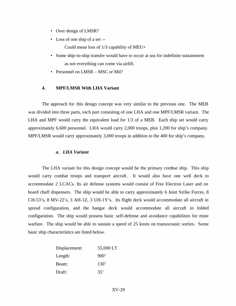
a. LHA Variant
The LHA variant for this design concept would be the primary combat ship. This ship
would carry combat troops and transport aircraft. It would also have one well deck to
accommodate 2 LCACs. Its air defense systems would consist of Free Electron Laser and on
board chaff dispensers. The ship would be able to carry approximately 6 Joint Strike Forces, 8
CH-53’s, 8 MV-22’s, 3 AH-1Z, 3 UH-1Y’s. Its flight deck would accommodate all aircraft in
spread configuration, and the hangar deck would accommodate all aircraft in folded
configuration. The ship would possess basic self-defense and avoidance capabilities for mine
warfare. The ship would be able to sustain a speed of 25 knots on transoceanic sorties. Some
basic ship characteristics are listed below.
Displacement: 55,000 LT
Length: 900’
Beam: 130’
Draft: 35’

XV-30
Internal Volume: 7.5 ft3
b. MPF/LMSR Variant
The primary mission for this ship would be to provide the Sea Base with supplies and
fleet support. The ship would have one well deck and could carry up to four LCACs. Its air
defense systems would consist of Free Electron Laser and on board chaff dispensers. The ship
would be able to carry approximately 3 CH-53’s, 4 MV-22’s, 1 AH-1Z, and 1 UH-1Y’s. Its
flight deck would accommodate all aircraft in spread configuration. The ship would possess
basic self-defense and avoidance capabilities for mine warfare. This ship would contain nearly
all the MEB’s medical and dental capabilities. This ship would also possess the transfer at sea
capabilities to interface with commercial and other sustainment platforms via cranes and LCACs.
The ship would be able to sustain a speed of 25 knots on transoceanic sorties.
c. Development Process
The development process started with requirements such as total payload, cargo volume,
and vehicle deck area. Each of this figures were plotted against and checked with previously
established design parameters. In this case, data from LPD-17, LHD, LSD, MPFS and LMSR
were used to compare the design requirements. In figure XV-6 the volume required for
provision is approximately 50,000 lbs. This figure was then compared against the displacement
to length ratio plotted from established platforms. The displacement to length ratio for the
LMSR variant was estimated at approximately 100 tons/ft. On figure XV-7, the required vehicle
deck area is approximately 130,000 ft2 for the LMSR variant and approximately 50,000 for the
LHA/MPF variant. The LMSR variant requirement is plotted against data from the existing
LMSR and MPFS data. The displacement to length ratio for this variant is estimated at
approximately 92 tons/ft. The requirement for the LHA/MPF is plotted against data from current
LPD, LSD, and LHD data and estimated at approximately 92 tons/ft. Using the same method,
the cargo volume is plotted against the ship’s cubic number and estimated at approximately
115,000 ft3. This relationship is illustrated in figure XV-8.

XV-31
Total Cargo Capacity [ft^3] vs Displ-Length ratio
0
10000
20000
30000
40000
50000
60000
70000
80000
90000
100000
60.00 65.00 70.00 75.00 80.00 85.00 90.00 95.00 100.00 105.00Displ-Length ratio
Car
go
Vo
lum
[ft
^3]
LMSR
MPSRON
LSD
LHD-1 LPD 17
LMSR VARIANT
Figure XV-6: Feasibility of LMSR Variant Compared to Other Platforms Cargo Capacity
Vehicle Deck Space vs Displacement-Length ratio
24995.48
12804.4
149951.36
72877.48 70000
20885.16
0
20000
40000
60000
80000
100000
120000
140000
160000
60.00 65.00 70.00 75.00 80.00 85.00 90.00 95.00 100.00 105.00Displ-Length ratio
Veh
icle
Dec
k A
rea
[ft^
2]
LMSR
MPSRON
LSDLHD-1
MPF2010
LPD 17
LHA/MPF VARIANT
LMSR VARIANT
Figure XV-7: Feasibility of LMSR and LHA/MPF Variant Compared to Other Platforms
Vehicle Deck Area.

XV-32
Cargo Volume [ft^3] vs Ship's Cubic Number
y = 28913e2E-05x
0
50,000
100,000
150,000
200,000
250,000
300,000
350,000
400,000
450,000
25,000 35,000 45,000 55,000 65,000 75,000 85,000 95,000 105,000 115,000 125,000 135,000 145,000 155,000
Cubic Number [L*B*D/100]
Car
go
Vo
lum
e [f
t^3]
LSD1
MPF 2010
LHD1
LPD17
LHA/MPF VARIANT
Figure XV-8: Feasibility of LHA/MPF Variant Compared to Other Platforms Cargo Volume.
Advantages:
• Division of equipment/troops is straight- forward in basic design layout.
• Forces are scalable (Each pair of ships=1/3 MEB). This allows easy replacement
of ships every thirty days or as required.
• Two ships are roughly the same size equating to one hull form with two variants.
Disadvantages
• If operating as a MEU (one pair of ships), and one is disabled either the entire
combat or support element of the MEU is lost.
• At-sea transfer needs to be more closely analyzed. Our alternative places two
cranes and at least one ramp onboard MPF to facilitate transfer with commercial
ships. Transfer between MPF and LHA can then be accomplished via LCAC’s,
underway replenishment. 5. X Ship Variant
The final design concept was the single ship or the “X” ship. This concept was very

XV-33
similar to the TSSE MPF 2010 design project of 1998. There would be approximately 6 ships
per MEB, but since every ship has the same capabilities it could also operate in pairs for a MEU
size contingency, or even as a single ship with a capability of ½ MEU. The ship would carry
troops, their equipment, and sustainment provisions for 30 days. It would also have at sea
transfer capabilities to interface with commercial and other supply ship to provide the Sea Base
with indefinite sustainment. Every ship would have the same number of aircraft, bigger flight
deck, and therefore have more airlift and transport capabilities than the previous alternatives.
The ship would also have a well deck to accommodate LCACs and LCUs. Modularity would
allow this ship to be stripped of its combat system, berthing, and other modules to effectively
converted into a re-supply ship. Some of the ship’s basic characteristics are listed below.
a. Development Process The development process for this concept was a Top Down requirements analysis. From
the requirements, total weight and volume were calculated for each ship. Table XV-9 illustrates
the basic ship’s characteristics, and Table XV-10 presents the estimated volume for each ship
section and its correspondent percentage.
Category Approximate Value Total Volume 8,056,952 Displacement 70000 Length 1000 Beam 150 Draft 40 Number of well-decks 2 Number of LCACS (per ship) 4
Table XV-9: Ship’s Basic Characteristics
Volume ft^3 Percent
Propulsion 500000 0.062058209
Auxiliary 0 0
Fuel 334200 0.041479707

XV-34
Habitability 607500 0.075400723
Combat Systems 15000 0.001861746
C4I 15000 0.001861746
Hospital 240000 0.02978794
Medical Facilities 0 0
Hangar 800000 0.099293134
Aircraft Maintenance 247500 0.030718813
Aircraft Equipment stowage 108000 0.013404573
Well Deck 300000 0.037234925
Miscellaneous 3000000 0.372349251
SHIP VOLUME 8056951.879
Table XV-10: Ship’s Volume
Advantages
• Redundancy is enhanced (all ships do the same thing, loss of one ship equals 1/6
loss in capability).
• Increased flight deck/aircraft capacity helps the Marine Corps to achieve STOM.
• All capabilities are on one ship, enhancing coordination of forces.
• All military equipment is stored on military ships, enhancing survivability.
Disadvantages
• Because everything has to fit on one ship, capabilities might have to be
compromised.
• These ships will be significantly larger.
• Must be re-supplied by other vessels.
Can be made easier by using non-militarized version as a sustainment ship
and transferring with vertical replenishment and LCAC’s
F. ANALYSIS OF ALTERNATIVES
In the analysis of alternatives phase, the objective was to evaluate each feasible
alternative, in terms of problem definition. In the case of the TSSE design, this problem
definition was directly linked with the capabilities required to perform Sea Basing, OMFT, and
STOM.

XV-35
The most important evaluation criteria was the ability of the concepts to maximize the
effectiveness of air, sea, and land assets in deployment, support, and reconstitution of MEB size
forces in a STOM environment. Other related capabilities were also considered:
• Ships must be able to scale operations to the MEU level in support of STOM.
• Ships must be able to support three coordinated and simultaneous attacks of a MEU size
force up to 200 NM inland.
• Ships must be able to allocate assets to maximize the support of marine units ashore.
• Ships must have the ability to prepare for a different type of mission while supporting a
current mission.
• Ships must have the ability to withdraw and re-deploy troops in an efficient manner.
• Ships must possess long-term sustainment capability.
• Ships must have the ability to interface with commercial shipping.
• Ships must maximize the options for on- load and off- load of troops, stores, fuel, and
combat supplies.
• Ships must provide support to other ships in the Sea Base.
• Ships must maximize the allocation of assets to minimize the degradation in system
performance in the event a unit is lost.
• Ships must maximize support and operations of aviation assets.
Area Mission Area % Weight
AMW Amphibious Warfare 40 LOG Logistics 28 FSO Fleet Support 11 C4ISR Command, Control, Computers 10

XV-36
MIW Mine Warfare 5 ASW Anti-submarine Warfare 2 MOB Mobility 2 USW Under Sea Warfare 1 AAW Anti-air Warfare 1
Table XV-11: Mission Area Weights
In order to prioritize the importance of each mission area, the team decided to apply a
mission area weight. The final weight factor results are listed in Table XV-11. This weight
would then be applied in the final concept evaluation.
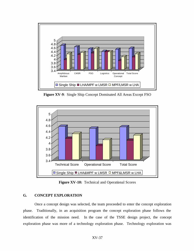
The final evaluation assessed all the mission areas, and the operational concept of each
alternative. The technical score consisted of a score of 1 to 5 assigned to each mission area. The
operational score was a score from 1 to 5 assigned to each of the alternative’s concepts of
operation. The technical score had a weight of 75% of the total score, and the operational score
had a weight of 25% of the total score. Appendix 16-2 lists the evaluation for each of the
alternatives.
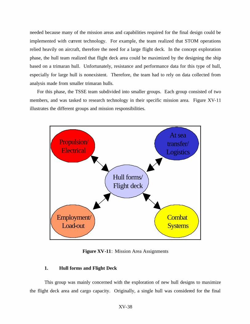
Figure XV-9 shows the results for the four most important mission areas and the
operational concept score for each of the alternatives. Figure XV-10 show the overall technical
score and operational score for the three alternatives. Based on this evaluation procedure, the
selected alternative was the single ship concept or X-Ship.
XV-37
3.43.63.8
44.24.44.64.8
5
AmphibiousWarfare
C4ISR FSO Logistics OperationalConcept
Total Score
Single Ship LHA/MPF w LMSR MPF/LMSR w LHA
Figure XV-9: Single Ship Concept Dominated All Areas Except FSO
3.4
3.6
3.8
4
4.2
4.4
4.6
4.8
5
Technical Score Operational Score Total Score
Single Ship LHA&MPF w LMSR MPF&LMSR w LHA
Figure XV-10: Technical and Operational Scores
G. CONCEPT EXPLORATION
Once a concept design was selected, the team proceeded to enter the concept exploration
phase. Traditionally, in an acquisition program the concept exploration phase follows the
identification of the mission need. In the case of the TSSE design project, the concept
exploration phase was more of a technology exploration phase. Technology exploration was
XV-38
needed because many of the mission areas and capabilities required for the final design could be
implemented with current technology. For example, the team realized that STOM operations
relied heavily on aircraft, therefore the need for a large flight deck. In the concept exploration
phase, the hull team realized that flight deck area could be maximized by the designing the ship
based on a trimaran hull. Unfortunately, resistance and performance data for this type of hull,
especially for large hull is nonexistent. Therefore, the team had to rely on data collected from
analysis made from smaller trimaran hulls.
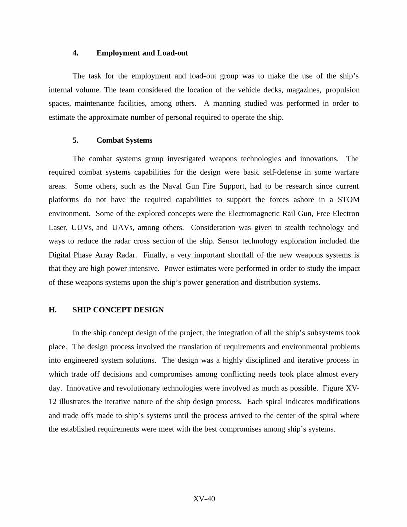
For this phase, the TSSE team subdivided into smaller groups. Each group consisted of two
members, and was tasked to research technology in their specific mission area. Figure XV-11
illustrates the different groups and mission responsibilities.
Hull forms/Flight deck
CombatSystems
Employment/Load-out
Propulsion/Electrical
At sea transfer
Hull forms/Flight deck
CombatSystems
Employment/Load-out
Propulsion/Electrical
At seatransfer/Logistics
Figure XV-11: Mission Area Assignments
1. Hull forms and Flight Deck
This group was mainly concerned with the exploration of new hull designs to maximize
the flight deck area and cargo capacity. Originally, a single hull was considered for the final

XV-39
design, but the requirement for a large flight deck eliminated this alternative. The second
alternative was to base the design in a catamaran. The catamaran hull allowed for the
arrangement of a larger flight deck with a negative trade off on internal volume due to the
smaller side hulls. The third alternative was the trimaran. This hull type gave the design the
large flight deck requirement without compromising internal cargo volume. In addition, the
trimaran proved to be a stable hull. Eventually, the trimaran hull became the hull of choice for
the final design.
2. Propulsion and Electrical Systems
The propulsion group explored innovations in propulsion and power distribution systems.
Consideration for propulsion systems were given to nuclear steam, fuel cell, gas turbine, diesel
engines, and electric drive technologies. Many Gas Turbines were studied and the LM600 and
LM2500+ seemed to be the best regarding power, Specific Fuel Consumption, and total fuel
consumption considerations for the design. Three alternatives were considered for the prime
movers: combination of either 4 LM6000, or 5 LM2500 or 3 LM6000 and 1 LM2500+. The third
alternative seemed to reach the power required with the minimum fuel consumption. Electrical
pods and conventional propellers were compared, and pods proved to have the highest efficiency
and maneuverability. Conventional electrical distribution, Integrated Power Systems, Radial
electrical distribution, DC zonal distribution, AC zonal distribution, and AC/DC zonal
distribution were studied considering the efficiency and high power requirements for the combat
system.
3. At Sea Transfer and Logistics Systems
Transfer at sea and logistics systems required efficient transfer, storage, and distribution
systems in order to supply the troops ashore. Some of the most important findings in this area
were technology innovation in motion compensated cranes, logistics automation and at sea
transfer technologies, hybrid linear actuators, omni directional vehicles, automated magazines
and stowage and retrieval system.
XV-40
4. Employment and Load-out
The task for the employment and load-out group was to make the use of the ship’s
internal volume. The team considered the location of the vehicle decks, magazines, propulsion
spaces, maintenance facilities, among others. A manning studied was performed in order to
estimate the approximate number of personal required to operate the ship.
5. Combat Systems
The combat systems group investigated weapons technologies and innovations. The
required combat systems capabilities for the design were basic self-defense in some warfare
areas. Some others, such as the Naval Gun Fire Support, had to be research since current
platforms do not have the required capabilities to support the forces ashore in a STOM
environment. Some of the explored concepts were the Electromagnetic Rail Gun, Free Electron
Laser, UUVs, and UAVs, among others. Consideration was given to stealth technology and
ways to reduce the radar cross section of the ship. Sensor technology exploration included the
Digital Phase Array Radar. Finally, a very important shortfall of the new weapons systems is
that they are high power intensive. Power estimates were performed in order to study the impact
of these weapons systems upon the ship’s power generation and distribution systems.
H. SHIP CONCEPT DESIGN
In the ship concept design of the project, the integration of all the ship’s subsystems took
place. The design process involved the translation of requirements and environmental problems
into engineered system solutions. The design was a highly disciplined and iterative process in
which trade off decisions and compromises among conflicting needs took place almost every
day. Innovative and revolutionary technologies were involved as much as possible. Figure XV-
12 illustrates the iterative nature of the ship design process. Each spiral indicates modifications
and trade offs made to ship’s systems until the process arrived to the center of the spiral where
the established requirements were meet with the best compromises among ship’s systems.

XV-41
Requirements
Baseline 1
Baseline 2
Baseline 3
Producibility
Operations and Support
Weights and Stability
Structures
Aux & Electric
Propulsion
Hull forms & Size
Space & Arragements
ASW
AAW
C4I
Figure XV-12: The Iterative Process of Ship Design (Source: TS 3002 Course Notes)
Another important step in the ship design process was the establishment of a ship design
philosophy. The ship design philosophy is a top- level statement of guidance for the design team
to assist them in carrying out the design trade-offs in a consistent manner. In the TSSE design,
the ship design philosophy focused in maximizing the air operations of the ship followed by
enhanced at sea transfer capabilities. The following list presents the entire ship design
philosophy for the TSSE design.
• Maximize Air lift/Air Ops capability.
• Enhanced At-sea transfer capability.
• Maximized modularity.
• Selective off- load.
• Survivability in a littoral environment.
• Maximize flexible employment on less than the MEU level.
XV-42
• Habitability/Support of MEU troops.
• Manning reduction.
• Port accessibility.
• Shipyard production capability.
• Combat systems offensive capability.
• Future growth potential.
• Use of commercial off the shelf technology.
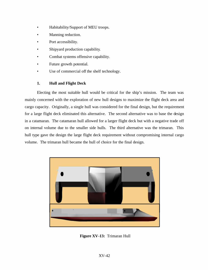
1. Hull and Flight Deck
Electing the most suitable hull would be critical for the ship’s mission. The team was
mainly concerned with the exploration of new hull designs to maximize the flight deck area and
cargo capacity. Originally, a single hull was considered for the final design, but the requirement
for a large flight deck eliminated this alternative. The second alternative was to base the design
in a catamaran. The catamaran hull allowed for a larger flight deck but with a negative trade off
on internal volume due to the smaller side hulls. The third alternative was the trimaran. This
hull type gave the design the large flight deck requirement without compromising internal cargo
volume. The trimaran hull became the hull of choice for the final design.
Figure XV-13: Trimaran Hull
XV-43
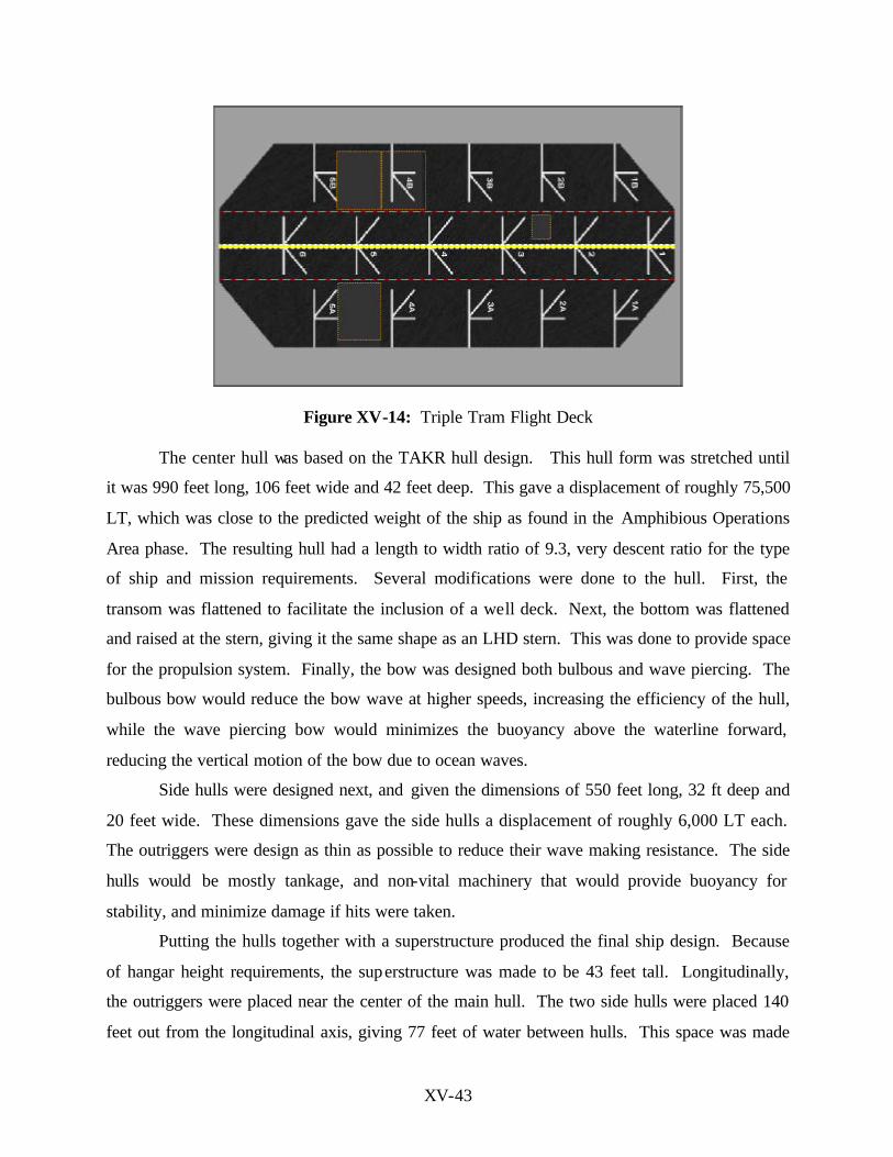
Figure XV-14: Triple Tram Flight Deck
The center hull was based on the TAKR hull design. This hull form was stretched until
it was 990 feet long, 106 feet wide and 42 feet deep. This gave a displacement of roughly 75,500
LT, which was close to the predicted weight of the ship as found in the Amphibious Operations
Area phase. The resulting hull had a length to width ratio of 9.3, very descent ratio for the type
of ship and mission requirements. Several modifications were done to the hull. First, the
transom was flattened to facilitate the inclusion of a well deck. Next, the bottom was flattened
and raised at the stern, giving it the same shape as an LHD stern. This was done to provide space
for the propulsion system. Finally, the bow was designed both bulbous and wave piercing. The
bulbous bow would reduce the bow wave at higher speeds, increasing the efficiency of the hull,
while the wave piercing bow would minimizes the buoyancy above the waterline forward,
reducing the vertical motion of the bow due to ocean waves.
Side hulls were designed next, and given the dimensions of 550 feet long, 32 ft deep and
20 feet wide. These dimensions gave the side hulls a displacement of roughly 6,000 LT each.
The outriggers were design as thin as possible to reduce their wave making resistance. The side
hulls would be mostly tankage, and non-vital machinery that would provide buoyancy for
stability, and minimize damage if hits were taken.
Putting the hulls together with a superstructure produced the final ship design. Because
of hangar height requirements, the superstructure was made to be 43 feet tall. Longitudinally,
the outriggers were placed near the center of the main hull. The two side hulls were placed 140
feet out from the longitudinal axis, giving 77 feet of water between hulls. This space was made
XV-44
to reduce wave interaction between the hulls, and to give enough space for an LCU to drive
between hulls. The vertical clearance under the superstructure is 30 feet. The LCUs would be
stored in the superstructure. When needed, they would drop down, and when not in use, they
would be winched back up into the superstructure. The superstructure ended up being octagonal
in shape, with sides angled at 12 degrees to reduce radar cross section area. Floodable
length calculations for this trimaran hull were done, and the minimum floodable length found
was 175 ft. The watertight bulkheads were placed so that no space would exceed 15% of
floodable length below the waterline. After the weight estimation was completed, the maximum
bending stress of the ship was calculated. The highest static bending stress was found to be
10,051 psi. Figures XV-15 and XV-16 illustrate longitudinal strength and floodable length
calculations.
The flight deck has dimensions of 770 by 300 ft for a total area of 230,000 square ft. The
triple tram design and the absence of a superstructure, enables the ship to conduct simultaneous
fixed and rotary wing operations with sufficient throughput to deploy, and sustain a MEB-sized
force ashore. The center runway will conduct STOVL aircraft operations. The 16 aircraft spots
were calculated using the standard 15 ft separation between rotating blades requirement in the
LHA/D manual for flight deck operations. The aircraft spots are capable of operating with
current and planned aircraft. The AERO heavy lift aircraft will operate using two aircraft spots
due to its larger size. The flight deck also has three aircraft elevators with a lift capacity of
70,000 lbs each. Elevators 2 and 3 on the port side can operate independently or simultaneously
to accommodate the larger AERO design heavy lift aircraft.

XV-45
Longitudinal Strength<---Aft (Feet) Fwd--->
1000.0a 500.0a 0.0a
-100.0
-50.0
0.0
50.0
100.0Weight x 1.5
Pt Load x 3.0Buoy. x 1.5
Shear x 140.0
B.M. x 39000.0
Figure XV-15: Longitudinal Strength
Floodable LengthsLocation
Length ft
1000.0a 500.0a 0.0a
0.0
100.0
200.0
300.0
400.0
500.0
Flood Length
Figure XV-16: Floodable Length
2. Propulsion and Electrical Systems
XV-46
The propulsion group explored innovation in propulsion and power distribution systems.
Consideration for propulsion systems were given to nuclear steam, fuel cell, gas turbine, diesel
engines, and electric drive technology. Analysis of prime movers focused mainly on Gas
Turbines. The LM600 and LM2500+ seemed to be the best suited for power, Specific Fuel
Consumption, and total fuel consumption requirements. Three different configurations were
considered. The first consisted of four LM6000. The second option required five LM2500, and
the third configuration consisted of three LM6000 and one LM2500+. From the three
configurations, the third alternative was selected because of its optimum power generation and
smaller fuel consumption. Waterjets, hydro drives, conventional propellers, and propulsion pods
were considered for propulsion. Due to weight, volume, and maneuverability at low speeds,
propulsion pods were selected. Propulsion motor selection was made among conventional
motors, High Temperature Superconducting AC synchronous motors, and DC super conducting
motors. The most feasible motor was the High Temperature Superconducting AC Synchronous
motors by American superconducting company for the design figure XV-17 illustrates speed vs.
power requirements.
For power distribution, Integrated Power Systems distribution was selected due to its
flexibility, modularized open architecture. The total installed electrical power is 159 MW.
Most of the electrical power generation is devoted for the weapon systems with a requirement of
120 MW. This energy will be stored in capacitor banks and fly-wheels, and made available to
the Electromagnetic Railgun and the Free Electron Laser. The Integrated Power Systems
architecture consists of 15 electrical zones in a combined AC and DC electrical distribution. To
maximize redundancy, four buses will run along the port and starboard sides of the ship, and
above and bellow the waterline. Two buses will carry 4160 volts AC, and the other 2 will carry
1100 volts DC.
AC buses will be connected to the zones through a step down transformer, and DC buses
will be connected through a Ships Service Converter Module and diode auctioneering giving as
output 900 volts DC for the port side and 850 volts DC on the starboard side. Through diode
auctioneering, if primary 900 volts DC power source is lost the secondary 850 volts DC power
source will be ready for back up to provide power for the vital loads. All sensitive AC and DC
equipment requiring a smooth waveform will be connected to the DC and AC buses through
Ships Service Converter Module and a Ships Service Inverter Module. The sensitive vital loads

XV-47
such as combat system computers or lighting are tied to both buses. Non-sensitive equipments
that do not require a smooth waveform are connected to the AC buses through a step down
transformers and SSCM figure XV-18 illustrates the IPS used in the TSSE concept design.
SPEED VS POWER
74000
223800
125000
2092026850
42400
0
50000
100000
150000
200000
250000
0 5 10 15 20 25 30 35
SPEED (KNTS)
PO
WE
R (
HP
)
Figure XV-17: Speed vs. Power Requirements
typical in zonePort bus 1100 V DC
Starboard bus 1100 V DC
SSCM1100v/900v
SSCM760v/110v
sensitiveDC load
SSIM900DC/450AC
60HZsensitiveVital load
SSCM1100v/850v
SSIM
Sensitive Vital load
SSIM900DC/450AC
60HZ
Sensitive AC load
-SSCM:dc-dc converter(2 per zone 1 providing power the other ready for backup)
-SSIM:dc-ac inverter
900V
850V
Port bus 4160 V AC
starboard bus 4160 V AC
Step down XFRM
Step down XFRM
450 VAC
450 VAC
STBDnonsensitive
Nonvital PWR
PORTnonsensitive
Nonvital load
nonsensitiveVital load
Circuit breakersDiode auctioneering
Circuit breakersDiode auctioneering
Figure XV-18: Integrated Power System 3. Logistic Systems
Transfer at sea and logistics systems require efficient transfer, storage, and distribution in
XV-48
order to effectively re-supply the troops ashore. Some of the most important incorporations to
the design in this area were technology innovation in motion compensated cranes, automation, at
sea transfer technologies, hybrid linear actuators, omni directional vehicles, automated
magazines, stowage and retrieval system. A standard 20 foot (twenty-foot equivalent unit –
TEU) container weighs approximately 12 tons. And each ship will carry an equivalent cargo
payload of 188 TEUs or 3500 long ton (LT). The required amount of fuel for the ACE, LCACs,
and LCUs to be carried by the Sea Base ships was calculated using the required sorties and burn
rate for each type of craft, and assuming an operational range of 250 NM for aircraft, and 50 NM
seaborne craft. A total 2.4 million gallons or 9195 LT of fuel is required. The amount of fuel
required by the Ground Combat Element was taken from the Center for Naval Analysis study
Fuel Requirements and Alternative Distribution Approaches in an Expeditionary Environment.
The transfer requirements for subsequent sustainment beyond the first 30 days were calculated to
be 15 TEUs per day per ship. In order to maximize the throughput and facilitate indefinite
sustainment, the primary modes for logistics transfer will be vertical and surface replenishment.
The ship’s trimaran hull form with its triple tram line would maximize flight deck operations for
logistics distribution. Although the need for ship to ship transfers was minimized, the ship will
still retain the capability to conduct transfers by Connected Replenishment using high lines or via
the motion compensated crane which is integrated into the automated warehouse. Handling of
liquid cargo will be via dedicated refueling positions on both port and starboard sides of the ship.
For Vertical Replenishment, there are 16 aircraft spots for airborne assets such as MV-22, and
heavy lift AERO design to handle up to pallet size loads. The well deck spots and LCU ramp
access between the hulls would support Surface Replenishment for larger TEUs size loads using
LCACs & LCUs. Once the cargo is onboard the ship, through either modes of trans fer, the ship
layout was arranged to allow for multiple unfettered access from the entry point to its intended
storage locations in the hangar, ammunition stronghold, warehouse staging area or the well deck.
A prototype of a motion compensated crane for the Mobile Offshore Base has been
developed by Scandia National Laboratory and Carderock. A smaller version crane system
integrated into the warehouse will provide Lift On/Lift Off capability to transfer of cargo either
from or to Combat Logistic, MPF, or commercial shipping. In its normal mode of operations,
the motion compensated crane would extend transversely from the warehouse lifting container
loads at sea state 4 with an estimated throughput of 29 TEUs per hour. The crane would operate

XV-49
flushed to the flight deck to minimize interference with flight deck operations. When not in use,
the crane would be recessed into the warehouse.
Two identical ordnance magazines are located on 3th and the 4th decks well below the
waterline in the center main hull. Their locations are transversely shielded by the side hulls. The
spaces are segregated by watertight bulkheads which are located 95 ft forward of magazines 2
and 4. Ordnance is stored in rack three pallets high. Magazines 2 and 4 have an area of 7,600 ft2
with a capacity to store 550 pallets each. Magazines 1 and 3 have an area of 6,500 ft2 with a
capacity to store 478 pallets each. The four magazines have a total capacity of 2,056 pallets.
Two ordnance elevators provide dual and redundant access to critical decks on the vehicle,
warehousing and flight deck levels.
The automated warehouse is segregated into three different sections. The first section of
the warehouse holds 72 TEUs. The second section contains 576 quadruple containers. The third
and largest sections contains 1344 pallets arrange in two sets of racks side by side, 8 pallets long,
and stacked 6 pallets high. A pigeon-hole design for storage allows for each pallet rack to have a
capacity for 96 pallets. Cargo movement will be conducted via the Linear Inductor Motor
conveyor currently under research. The conveyor will have a capacity to handle up to 12,000
lbs, and will provide a significant improvement in cargo movement. It is mounted along the
port side of the main hull to provide rapid access through the hangar bay, to the LCU ports, and
to the aircraft elevators.
For the warehouse, the use of automation enhances the efficiency logistical support and
will allow selective offloading. An electronic gantry located across the staging area, will
electronically scan all cargo prior to entry into the warehouse. Once inside the warehouse, the 2
overhead cranes will have access to any point in the warehouse. The center transit lane is 10 ft
wide and will allow access by omni directional vehicle s and automated forklifts which will move
the cargo from the staging/processing area to storage or the Linear Inductor Motor conveyor.

XV-50
Figure XV-19: Automated Magazine (Source: Office of Naval Research)
L o a d P l a t f o r m
M o t o r M o d u l e s a n d R o l l e r R a i l s( f l u s h w i t h f l o o r )
R e a c t i o n P l a t e s( n o t t o s c a l e )
N o t i o n a l A l i g n m e n t R o l l e r s
S u p p o r t S t r u c t u r e
B r a k e S y s t e m L o c a t i o n( n o t s h o w n )
V e r t i c a l A l i g n m e n t R a i l s
Figure XV-20: Linear Inductor Motor (LIM) Conveyor Belt.
(Source: Office of Naval Research)
4. Combat Systems
The required combat systems capabilities for the design were basic self-defense, but an
extremely important mission for the ship was the Naval Gun Fire Support to provide the forces
ashore with effective fires in a STOM environment. Some of the selected weapon systems were
the Electromagnetic Rail Gun, Free Electron Laser, Unmanned Underwater and Aerial Vehicles
among others. Consideration was given to stealth technology and ways to reduce the radar cross
section of the ship. Sensor technology exploration included the Digital Phase Array Radar.

XV-51
Figures XV-21 and 23 illustrate the major weapon systems incorporated to the TSSE design and
their area coverage.
Electromagnetic Railgun/
Free Electron Laser (FEL) 3-D Phase Array Radar Unmanned Underwater
Sea Rolling Airframe Missile Forward Looking Infrared (FLIR)
Figure XV-21: Weapon and Sensor Systems
JSF/OTHER BATTLE GROUP ASSETS
10-100+ km
FEL/RAIL GUN
4-10 km
FEL/SEA RAM/RAIL GUN
0-4 km
JSF/OTHER BATTLE GROUP ASSETS
10-100+ km
FEL/RAIL GUN
4-10 km
FEL/SEA RAM/RAIL GUN
0-4 km
Figure XV-22: Area Coverage for Major Weapon Systems
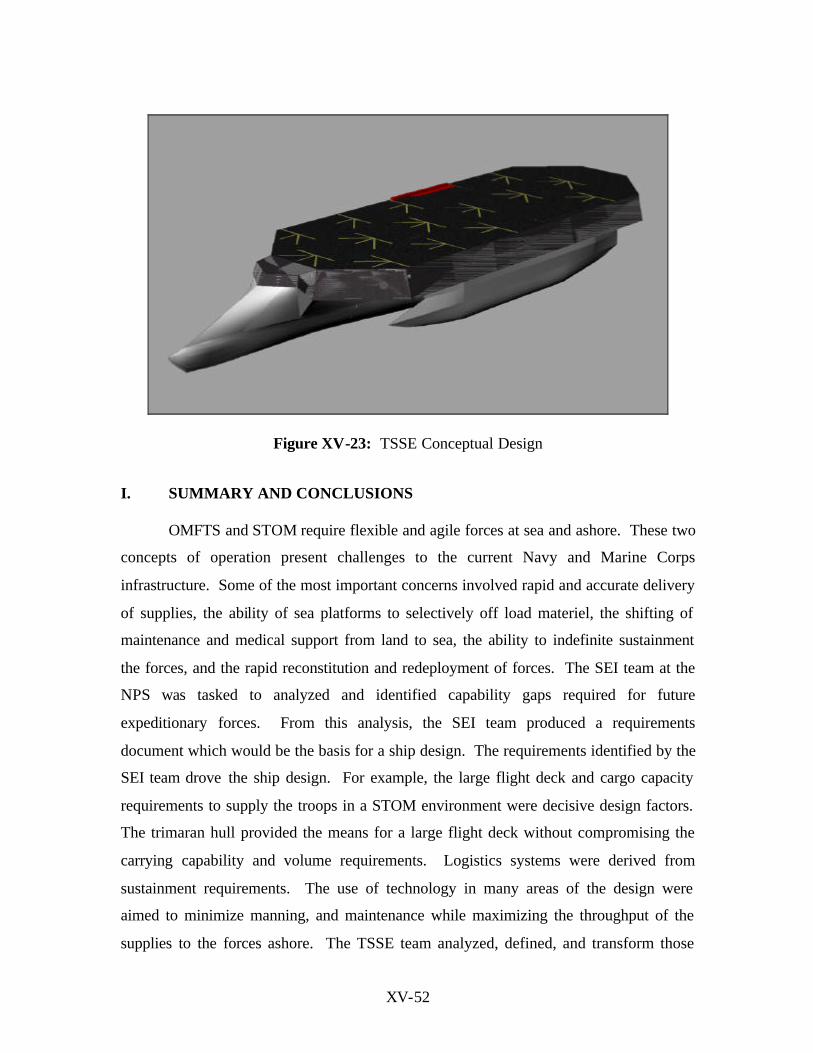
XV-52
Figure XV-23: TSSE Conceptual Design
I. SUMMARY AND CONCLUSIONS
OMFTS and STOM require flexible and agile forces at sea and ashore. These two
concepts of operation present challenges to the current Navy and Marine Corps
infrastructure. Some of the most important concerns involved rapid and accurate delivery
of supplies, the ability of sea platforms to selectively off load materiel, the shifting of
maintenance and medical support from land to sea, the ability to indefinite sustainment
the forces, and the rapid reconstitution and redeployment of forces. The SEI team at the
NPS was tasked to analyzed and identified capability gaps required for future
expeditionary forces. From this analysis, the SEI team produced a requirements
document which would be the basis for a ship design. The requirements identified by the
SEI team drove the ship design. For example, the large flight deck and cargo capacity
requirements to supply the troops in a STOM environment were decisive design factors.
The trimaran hull provided the means for a large flight deck without compromising the
carrying capability and volume requirements. Logistics systems were derived from
sustainment requirements. The use of technology in many areas of the design were
aimed to minimize manning, and maintenance while maximizing the throughput of the
supplies to the forces ashore. The TSSE team analyzed, defined, and transform those
XV-53
requirements into a ship design that would enable effective Sea Base operations, and if
built would become the new face of ExWar.