Xtreme Products Inc - Mud-Throwers by loosening the lug nuts on both front tires. Raise the unit,...
5
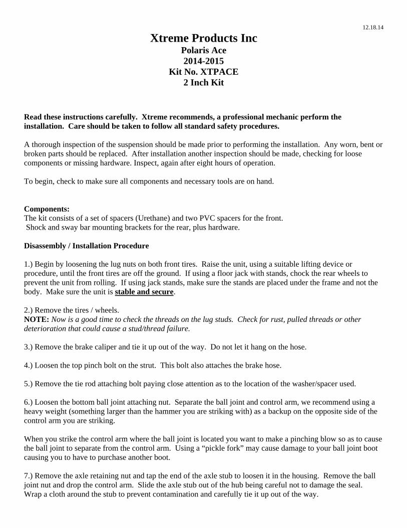
12.18.14 Xtreme Products Inc Polaris Ace 2014-2015 Kit No. XTPACE 2 Inch Kit Read these instructions carefully. Xtreme recommends, a professional mechanic perform the installation. Care should be taken to follow all standard safety procedures. A thorough inspection of the suspension should be made prior to performing the installation. Any worn, bent or broken parts should be replaced. After installation another inspection should be made, checking for loose components or missing hardware. Inspect, again after eight hours of operation. To begin, check to make sure all components and necessary tools are on hand. Components: The kit consists of a set of spacers (Urethane) and two PVC spacers for the front. Shock and sway bar mounting brackets for the rear, plus hardware. Disassembly / Installation Procedure 1.) Begin by loosening the lug nuts on both front tires. Raise the unit, using a suitable lifting device or procedure, until the front tires are off the ground. If using a floor jack with stands, chock the rear wheels to prevent the unit from rolling. If using jack stands, make sure the stands are placed under the frame and not the body. Make sure the unit is stable and secure. 2.) Remove the tires / wheels. NOTE: Now is a good time to check the threads on the lug studs. Check for rust, pulled threads or other deterioration that could cause a stud/thread failure. 3.) Remove the brake caliper and tie it up out of the way. Do not let it hang on the hose. 4.) Loosen the top pinch bolt on the strut. This bolt also attaches the brake hose. 5.) Remove the tie rod attaching bolt paying close attention as to the location of the washer/spacer used. 6.) Loosen the bottom ball joint attaching nut. Separate the ball joint and control arm, we recommend using a heavy weight (something larger than the hammer you are striking with) as a backup on the opposite side of the control arm you are striking. When you strike the control arm where the ball joint is located you want to make a pinching blow so as to cause the ball joint to separate from the control arm. Using a “pickle fork” may cause damage to your ball joint boot causing you to have to purchase another boot. 7.) Remove the axle retaining nut and tap the end of the axle stub to loosen it in the housing. Remove the ball joint nut and drop the control arm. Slide the axle stub out of the hub being careful not to damage the seal. Wrap a cloth around the stub to prevent contamination and carefully tie it up out of the way.
Transcript of Xtreme Products Inc - Mud-Throwers by loosening the lug nuts on both front tires. Raise the unit,...
12.18.14
Xtreme Products Inc
Polaris Ace 2014-2015
Kit No. XTPACE 2 Inch Kit
Read these instructions carefully. Xtreme recommends, a professional mechanic perform the installation. Care should be taken to follow all standard safety procedures. A thorough inspection of the suspension should be made prior to performing the installation. Any worn, bent or broken parts should be replaced. After installation another inspection should be made, checking for loose components or missing hardware. Inspect, again after eight hours of operation. To begin, check to make sure all components and necessary tools are on hand. Components: The kit consists of a set of spacers (Urethane) and two PVC spacers for the front. Shock and sway bar mounting brackets for the rear, plus hardware. Disassembly / Installation Procedure 1.) Begin by loosening the lug nuts on both front tires. Raise the unit, using a suitable lifting device or procedure, until the front tires are off the ground. If using a floor jack with stands, chock the rear wheels to prevent the unit from rolling. If using jack stands, make sure the stands are placed under the frame and not the body. Make sure the unit is stable and secure. 2.) Remove the tires / wheels. NOTE: Now is a good time to check the threads on the lug studs. Check for rust, pulled threads or other deterioration that could cause a stud/thread failure. 3.) Remove the brake caliper and tie it up out of the way. Do not let it hang on the hose. 4.) Loosen the top pinch bolt on the strut. This bolt also attaches the brake hose. 5.) Remove the tie rod attaching bolt paying close attention as to the location of the washer/spacer used. 6.) Loosen the bottom ball joint attaching nut. Separate the ball joint and control arm, we recommend using a heavy weight (something larger than the hammer you are striking with) as a backup on the opposite side of the control arm you are striking. When you strike the control arm where the ball joint is located you want to make a pinching blow so as to cause the ball joint to separate from the control arm. Using a “pickle fork” may cause damage to your ball joint boot causing you to have to purchase another boot. 7.) Remove the axle retaining nut and tap the end of the axle stub to loosen it in the housing. Remove the ball joint nut and drop the control arm. Slide the axle stub out of the hub being careful not to damage the seal. Wrap a cloth around the stub to prevent contamination and carefully tie it up out of the way.

NOTE: PAY CLOSE ATTENTION TO THE INNER PLUNGE SOCKET AND DO NOT DISENGAGE. IF YOU DO, CAREFULLY WORK THE BEARINGS BACK INTO THE SOCKET. FAILURE TO DO THIS WILL CAUSE YOU TO DISASSEMBLE THE UNIT BACK TO THIS POINT AND START OVER. IN WORST CASES YOU CAN DAMAGE THE SOCKET AND HAVE TO REPLACE THE AXLE. 8.) Insert the PVC Spacer into the strut housing making sure it is fully seated against the bottom of the housing. Also make sure it will not contact the CV boot also. (The PVC Spacers is already cut to aid the process.) 9.)Place the Polyurethane spacer over the strut and insert the strut back into the housing. Lower the strut in the housing until it seats firmly on the spacer and the coil is sitting in the retainer groove on the Urethane spacer. Tighten the lower pinch bolt. 10.) Take the stub and reinsert into the hub. Do not try to insert it all the way. Take the lower control arm and lift it up and reinstall the ball joint into the control arm. Tighten the ball joint nut finger tight. Place a jack under the control arm to help hold it in place. 11.) You may now insert the stub into the hub and through the bearings. Be sure the inner plunge socket is engaged properly. 12.) Complete the reassembly in the reverse order that you used to disassemble. When you install the axle retaining nut, tighten this firmly making sure the bearings are seated and the axle stub is all the way into the hub. Look at the back of the hub and be sure the stub is all the way in. 13.) Make sure the coil and spacer are seated properly then using the jack you placed under the control arm apply pressure to the control arm, reattach all the components you removed in the reverse order. Make sure the strut is down in the housing and firmly against the PVC spacer. You may check this by inserting your finger through the bottom and checking to be sure the strut is touching the PVC spacer. If not you may use a pry bar inserted in the coil to pry down on the strut until it is in position. Tighten and replace all “cotter pins” you removed. 14.) Proceed to the other side and repeat the steps listed.
The PVC spacer is inserted into the aluminum strut housing. The strut is inserted and fully seated down against the PVC spacer. The Urethane spacer is installed onto the strut housing, with the factory steel washer underneath it. The spring is sitting inside the lip of the Urethane spacer

This shows how to push the strut down on the PVC spacer. You may have to apply pressure to the strut on some installations. When you have the strut seated on the spacer tighten the lower pinch bolt.
REAR Disassembly / Reassembly
15.) Lift the rear of the bike and place jack stands to support the weight and stabilize the bike. Remove the lower shock mounting bolt. Install the sway bar bracket as shown with the supplied bolt/nut.
16.) Attach the lower end of the sway bar to the new bracket using the supplied hardware. Repeat these steps on the opposite side. Leave all bolts loose until completely finished
View is of Drivers Side
17.) Install the new shock mounting brackets as shown in the picture and be sure to install the sleeve in the factory shock mount. The 01 bracket goes on the outside front of the factory shock mount. The 02 bracket goes to the inside rear of the factory shock mount, with the supplied sleeve. Tighten all hardware at this point
03 Bracket

18.) Repeat the above procedure on the other side. Reinstall tires/wheels and lower machine off jack/jackstands. Tighten all hardware at this point.
01 Bracket
02 Bracket
02 Bracket Inside factory shock mount
Sleeve
01 Bracket Outside factory shock mount

Limited Lifetime Warranty / Warnings
Your Xtreme Products Inc product is covered by the Limited Warranty explained below that gives you specific legal rights. This limited warranty is the only warranty Xtreme makes in connection with your product purchase. Xtreme Products Inc neither assumes nor authorizes any retailer or other person or entity to assume for it any other obligation or liability in connection with this product or limited warranty. What is covered? Subject to the terms below, Xtreme Products will repair or replace its products found defective in materials or workmanship for so long as the original purchaser owns the ATV/UTV on which the product was originally installed. Your warrantor is Xtreme Products Inc. What is not covered? Your Xtreme Products Limited Warranty does not cover products, parts or ATVs/UTVs that Xtreme Products determines to have been damaged by or subjected to: Alteration, modification or failure to maintain. Normal wear and tear (bushings, tie-rod ends, axles, bearings, etc.). Scratches or defects in product finishes (powder
coating, plating, etc.), Damage to or resulting from racing, competitions, contests, jumping or activity causing the suspension to limit-out. Accidents, impact by rocks, trees, obstacles or other aspects of the environment. Theft, vandalism or other intentional damage. Remedy Limited to Repair / Replacement The exclusive remedy provided hereunder shall, upon Xtreme’s inspection and at Xtreme’s option, be either repair or replacement of product or parts covered under this Limited Warranty. Customers requesting warranty consideration should contact Xtreme Products Inc. by phone (1-888-283-0977) to obtain a Returned Goods Authorization number. All removal, shipping and installation costs are customer’s responsibility. If a replacement part is needed before the Xtreme Products part in question can be returned, you must first purchase the replacement part. Then, if the part in question is deemed warrantable, you will be credited / refunded. Other Limitations - Exclusion of Damages - Your Rights under State Law Neither Xtreme Products nor your independent Xtreme Products dealers are responsible for any time loss, rental costs,
or for any incidental, consequential or other damages you may have incurred. This Limited Warranty gives you specific rights. You may also have other rights that vary from state-to-state. For
example, while all implied warranties are disclaimed herein, any implied warranty required by law is limited to the terms of our Limited Lifetime Warranty as described above. Some states do not allow limitations of how long an implied warranty lasts and / or do not allow the exclusion or limitation of incidental or consequential damages, so the limitations and exclusions herein may not apply to you.
Important Product Use and Safety Information / Warnings As a general rule, the taller a unit is, the easier it will roll over. Offset, as much as possible, what is lost in rollover resistance by increasing tire track width: In other words, go “wide” as you go “tall”. Always use as wide a tire and wheel combination as feasible to enhance vehicle stability. We strongly recommend, because of rollover possibility, you should avoid situations where a side rollover may occur. Generally, braking performance and capabilities are decreased when significantly larger / heavier tires and wheels are used (take this into consideration while driving). Also, using tires that are taller or shorter than factory height will cause an erroneous speedometer reading. Do not add, alter or fabricate any factory or aftermarket parts to increase vehicle height over the intended height of the Xtreme Products product purchased. Mixing or adding different component brands are not recommended.