XT-19G IP Phone User Manual
110
XT-19G IP Phone User Manual
Transcript of XT-19G IP Phone User Manual

XT-19G IP Phone
User Manual
Directory
Directory ............................................................................................................................................................................. 2
1 Safety Instruction.......................................................................................................................................................... 7
2 Overview ......................................................................................................................................................................... 8
2.1 Overview ............................................................................................................................................................. 8
2.2 Packing Contents .............................................................................................................................................. 9
3 Desktop Installation ................................................................................................................................................... 10
3.1 PoE and the use of external power adapters .............................................................................................. 10
3.2 Desktop and wall mounted method .............................................................................................................. 11
4 Appendix Table............................................................................................................................................................ 13
4.1 Appendix I - Icon .............................................................................................................................................. 13
4.2 Appendix II - Keyboard character query table ............................................................................................. 14
4.3 Appendix III –LED Definition .......................................................................................................................... 17
5 Introduction to the User ............................................................................................................................................ 18
5.1 Instruction of Keypad ...................................................................................................................................... 18
5.2 Using Handset / Hands-free Speaker / Headphone ................................................................................... 19
5.3 Idle Screen ....................................................................................................................................................... 20
5.4 Phone Status .................................................................................................................................................... 21
5.5 Web Management ........................................................................................................................................... 22
5.6 Network Configurations .................................................................................................................................. 22
5.7 SIP Configurations .......................................................................................................................................... 23
6 Basic Function ............................................................................................................................................................. 25
6.1 Making Phone Calls ........................................................................................................................................ 25
6.2 Answering Calls ............................................................................................................................................... 26
6.2.1 Talking ...................................................................................................................................................... 27
6.2.2 Make / Receive Second Call ................................................................................................................. 27
6.3 End of the Call ................................................................................................................................................. 28
6.4 Redial ................................................................................................................................................................ 28
6.5 Auto-Answering ............................................................................................................................................... 29
6.6 Callback ............................................................................................................................................................ 30
6.7 Mute ................................................................................................................................................................... 31
6.7.1 Mute the Call ........................................................................................................................................... 31
6.7.2 Ringing Mute ........................................................................................................................................... 31
6.8 Call Hold/Resume............................................................................................................................................ 32
6.9 DND ................................................................................................................................................................... 32
6.10 Call Forward ................................................................................................................................................... 34
6.11 Call Transfer ................................................................................................................................................... 36
6.11.1 Blind transfer ......................................................................................................................................... 36
6.11.2 Semi-Attended transfer ....................................................................................................................... 36
6.11.3 Attended transfer .................................................................................................................................. 37
6.12 Call Waiting .................................................................................................................................................... 37
6.13 Conference ..................................................................................................................................................... 38
6.13.1 Local Conference ................................................................................................................................. 38
6.13.2 Network Conference ............................................................................................................................ 39
6.14 Call Park ......................................................................................................................................................... 40
6.15 Pick Up ............................................................................................................................................................ 40
6.16 Anonymous Call ............................................................................................................................................ 41
6.16.1 Anonymous Call ................................................................................................................................... 41
6.16.2 Ban Anonymous Call ........................................................................................................................... 42
6.17 Hotline ............................................................................................................................................................. 43
6.18 Emergency Call ............................................................................................................................................. 44
7 Advance Function ....................................................................................................................................................... 46
7.1 BLF (Busy Lamp Field) ................................................................................................................................... 46
7.1.1 Configure the BLF Functionality ........................................................................................................... 46
7.1.2 Use the BLF Function ............................................................................................................................ 47
7.2 BLF List ............................................................................................................................................................. 47
7.3 Record ............................................................................................................................................................... 48
7.3.1 Server Record ......................................................................................................................................... 48
7.3.2 SIP INFO Record .................................................................................................................................... 49
7.4 Agent ................................................................................................................................................................. 49
7.5 Intercom ............................................................................................................................................................ 51
7.6 MCAST .............................................................................................................................................................. 51
7.7 SCA(Shared Call Appearance) ................................................................................................................ 52
7.8 Message ........................................................................................................................................................... 55
7.8.1 SMS .......................................................................................................................................................... 55
7.8.2 MWI(Message Waiting Indicator) .................................................................................................... 56
7.9 SIP Hotspot ...................................................................................................................................................... 57
8 Phone Settings ............................................................................................................................................................ 60
8.1 Basic Settings .................................................................................................................................................. 60
8.1.1 Language ................................................................................................................................................. 60
8.1.2 Time & Date ............................................................................................................................................ 60
8.1.3 Screen ...................................................................................................................................................... 62
8.1.3.1 Brightness and backlight ............................................................................................................ 62
8.1.3.2 Screen Saver ............................................................................................................................... 63
8.1.4 Ring .......................................................................................................................................................... 63
8.1.5 Voice Volume .......................................................................................................................................... 63
8.1.6 Greeting Words ....................................................................................................................................... 64
8.1.7 Reboot ...................................................................................................................................................... 64
8.2 Phone Book ...................................................................................................................................................... 64
8.2.1 Local Contact .......................................................................................................................................... 64
8.2.1.1 Add / Edit / Delete Contact ........................................................................................................ 65
8.2.1.2 Add / Edit / Delete Group ........................................................................................................... 65
8.2.1.3 Browse and Add / Remove Contacts in Group ....................................................................... 66
8.2.2 Blacklist .................................................................................................................................................... 66
8.2.3 Cloud Phone Book ................................................................................................................................. 67
8.2.3.1 Configure Cloud Phone book .................................................................................................... 67
8.2.3.2 Downloading Cloud Phone book .............................................................................................. 68
8.3 Call Log ............................................................................................................................................................. 68
8.4 Function Key .................................................................................................................................................... 69
8.5 Headset ............................................................................................................................................................. 70
8.5.1 Wired Headset ........................................................................................................................................ 70
8.5.2 EHS Headset .......................................................................................................................................... 71
8.6 Advanced .......................................................................................................................................................... 71
8.6.1 Line Configurations ................................................................................................................................ 71
8.6.2 Network Settings..................................................................................................................................... 72
8.6.2.1 Network Settings ......................................................................................................................... 72
8.6.2.2 QoS & VLAN ................................................................................................................................ 74
8.6.2.3 VPN ............................................................................................................................................... 74
8.6.2.4 Web Server Type ........................................................................................................................ 75
8.6.3 Set The Secret Key ................................................................................................................................ 75
8.6.4 Maintenance ............................................................................................................................................ 77
8.6.5 Firmware Upgrade .................................................................................................................................. 79
8.6.6 Factory Reset .......................................................................................................................................... 81
9 Web Configurations ................................................................................................................................................... 82
9.1 Web Page Authentication ............................................................................................................................... 82
9.2 System >> Information.................................................................................................................................... 82
9.3 System >> Account ......................................................................................................................................... 82
9.4 System >> Configurations .............................................................................................................................. 82
9.5 System >> Upgrade ........................................................................................................................................ 83
9.6 System >> Auto Provision .............................................................................................................................. 83
9.7 System >> Tools .............................................................................................................................................. 83
9.8 System >> Reboot Phone .............................................................................................................................. 83
10 Network >> Basic ...................................................................................................................................................... 84
10.1 Network >> Service Port .............................................................................................................................. 84
10.2 Network >> VPN ............................................................................................................................................ 84
10.3 Network >> Advanced .................................................................................................................................. 85
10.4 Line >> SIP ..................................................................................................................................................... 85
10.5 Line >> SIP Hotspot ...................................................................................................................................... 89
10.6 Line >> Dial Plan ........................................................................................................................................... 90
10.7 Line >> Basic Settings .................................................................................................................................. 92
10.8 Phone settings >> Features ........................................................................................................................ 93
10.9 Phone settings >> Media Settings .............................................................................................................. 96
10.10 Phone settings >> MCAST ........................................................................................................................ 97
10.11 Phone settings >> Action ........................................................................................................................... 97
10.12 Phone settings >> Time/Date .................................................................................................................... 97
10.13 Phone settings >> Tone ............................................................................................................................. 98
10.14 Phone settings >> Advanced .................................................................................................................... 99
10.15 Phonebook >> Contact .............................................................................................................................. 99
10.16 Phonebook >> Cloud phonebook ........................................................................................................... 100
10.17 Phonebook >> Call List ............................................................................................................................ 101
10.18 Phonebook >> Web Dial .......................................................................................................................... 101
10.19 Phonebook >> Advanced ........................................................................................................................ 101
10.20 Call Log ....................................................................................................................................................... 102
10.21 Function Key >> Function Key ................................................................................................................ 102
10.22 Function Key >> Softkey .......................................................................................................................... 103
10.23 Function Key >> Advanced ..................................................................................................................... 104
10.24 Application >> Manage Recording ......................................................................................................... 104
10.25 Security >> Web Filter .............................................................................................................................. 104
10.26 Security >> Trust Certificates .................................................................................................................. 105
10.27 Security >> Device Certificates ............................................................................................................... 105
10.28 Security >> Firewall .................................................................................................................................. 106
10.29 Device Log >> Device Log ...................................................................................................................... 107
11 Troubleshooting...................................................................................................................................................... 108
11.1 Get Device System Information ................................................................................................................ 108
11.2 Reboot Device ............................................................................................................................................. 108
11.3 Reset Device to Factory Default ............................................................................................................... 108
11.4 Screenshot ................................................................................................................................................... 108
11.5 Network Packets Capture .......................................................................................................................... 109
11.6 Get Log Information .................................................................................................................................... 109

11.7 Common Trouble Cases………………………………………………………………………….......…109
1 Safety Instruction
Please read the following safety notices before installing or using this unit. They are crucial for the safe and
reliable operation of the device.
Please use the external power supply that is included in the package. Other power supply may cause
damage to the phone and affect the behavior or induce noise.
Before using the external power supply in the package, please check the home power voltage.
Inaccurate power voltage may cause fire and damage.
Please do not damage the power cord. If power cord or plug is impaired, do not use it because it may
cause fire or electric shock.
Do not drop, knock or shake the phone. Rough handling can break internal circuit boards.
This phone is designed for indoor use. Do not install the device in places where there is direct sunlight.
Also, do not put the device on carpets or cushions. It may cause fire or breakdown.
Avoid exposure the phone to high temperature or below 0℃ or high humidity.
Avoid wetting the unit with any liquid.
Do not attempt to open it. Non-expert handling of the device could damage it. Consult your authorized
dealer for help, or else it may cause fire, electric shock and breakdown.
Do not use harsh chemicals, cleaning solvents, or strong detergents to clean it. Wipe it with a soft cloth
that has been slightly dampened in a mild soap and water solution.
When lightning, do not touch power plug, it may cause an electric shock.
Do not install this phone in an ill-ventilated place. You are in a situation that could cause bodily injury.
Before you work on any equipment, be aware of the hazards involved with electrical circuitry and be
familiar with standard practices for preventing accidents.
2 Overview
2.1 Overview
XT-19G are a kind of telephones designed for small and medium-sized enterprises and families. It’s greatly
improve enterprise production efficiency with advanced design, high cost performance, paperless office tool.
It is not only a desktop phone, but also an elegant article that puts in the sitting room or office.
The device is the latest generation of IP Phone, which supports many excellent features, such as
high-definition voice, headphones and high-performance echo cancellation full duplex speaker, Fast Ethernet,
QoS, encryption transmission, automatic configuration, new system, smooth operation, flat interface settings
and many other advantages.
For enterprise users, it’s the cost-effective office equipment, while realizing environmental protection, they
also provide convenient operation. For family users, it’s the highly efficient communication device. Users can
flexibly configure and define the functions of two DSS keys, space saving and cost. It will be an ideal choice
for enterprise users and family users who pursue the high quality and high efficiency.
In order to help some interested users better understand the details of the product, this user manual can be
used as a reference guide for the use of XT-19G. This document may not be applicable to the latest version of
the software. If you have any questions, you can use the help prompt interface of the device phone, or
download and update your user manual from the official website.

2.2 Packing Contents
Phone Handset
Receiver cable Stand Network cable
Power adapter (Optional) Hanging bracket

3 Desktop Installation
3.1 PoE and the use of external power adapters
XT-19G support two power supply modes from external power adapter or over Ethernet (PoE) complied
switch.
PoE power supply saves the space and cost of providing the device additional power outlet. With a PoE
switch, the device can be powered through a single Ethernet cable which is also used for data transmission.
By attaching UPS system to PoE switch, the device can keep working at power outage just like traditional
PSTN telephone which is powered by the telephone line.
For users who do not have PoE equipment, the traditional power adaptor should be used. If the device is
connected to a PoE switch and power adapter at the same time, the power adapter will be used in priority and
will switch to PoE power supply once it fails.
Use standard power adapters and PoE conforming to specifications to ensure proper operation of equipment.
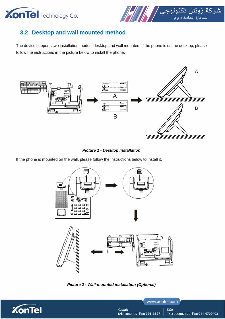
3.2 Desktop and wall mounted method
The device supports two installation modes, desktop and wall mounted. If the phone is on the desktop, please
follow the instructions in the picture below to install the phone.
Picture 1 - Desktop installation
If the phone is mounted on the wall, please follow the instructions below to install it.
Picture 2 - Wall-mounted installation (Optional)

Connect the power adapter, network, PC, phone and earphone to the appropriate port as shown in the picture
below.
Picture 3 - Connecting to the Device
Table 1 - Hardware Interface Description
Index Interface Description
① Power Interface Connecting Power Adapter
② Network Interface Connecting to LAN or Internet
③ PC Port Network Interface for Connecting Computer
④ Headset Interface Connecting Headset
⑤ Receiver Interface Connecting Microphone Receiver
4 Appendix Table
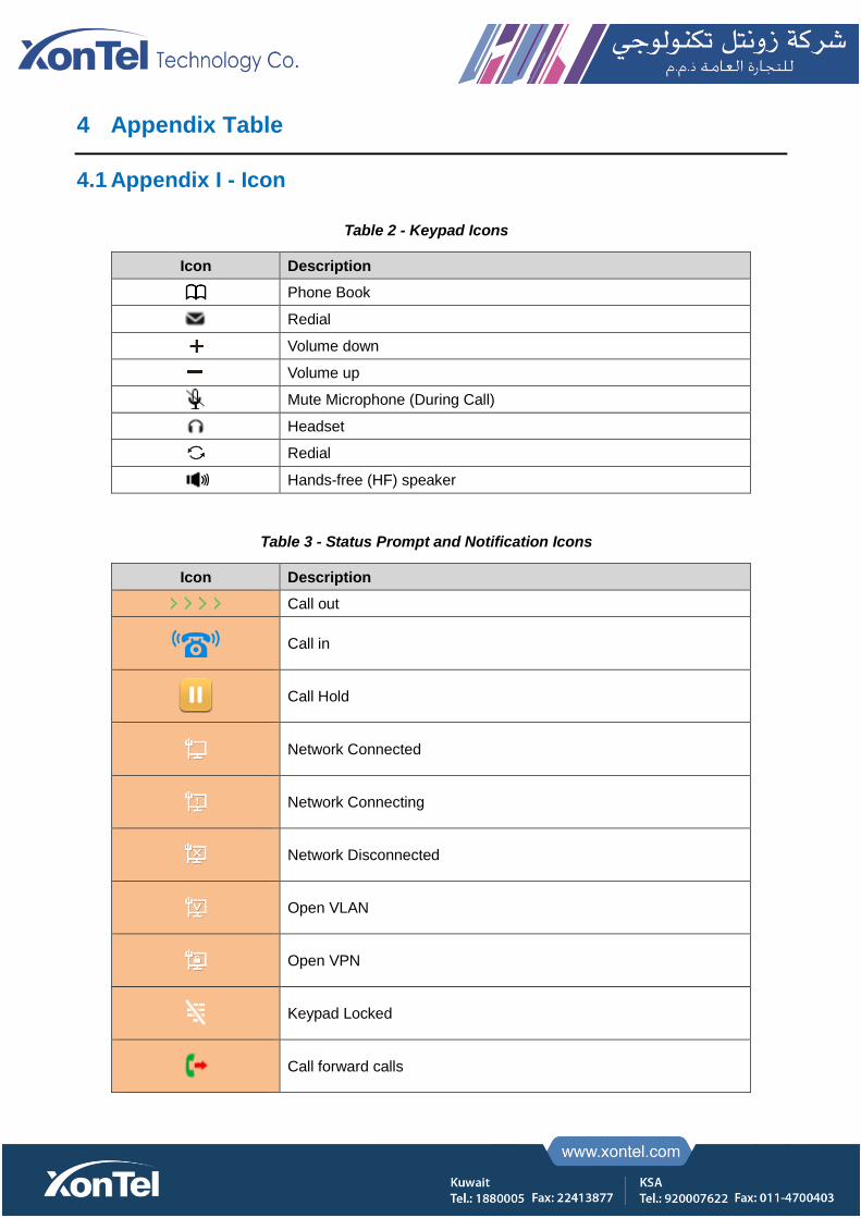
4.1 Appendix I - Icon
Table 2 - Keypad Icons
Icon Description
Phone Book
Redial
Volume down
Volume up
Mute Microphone (During Call)
Headset
Redial
Hands-free (HF) speaker
Table 3 - Status Prompt and Notification Icons
Icon Description
Call out
Call in
Call Hold
Network Connected
Network Connecting
Network Disconnected
Open VLAN
Open VPN
Keypad Locked
Call forward calls
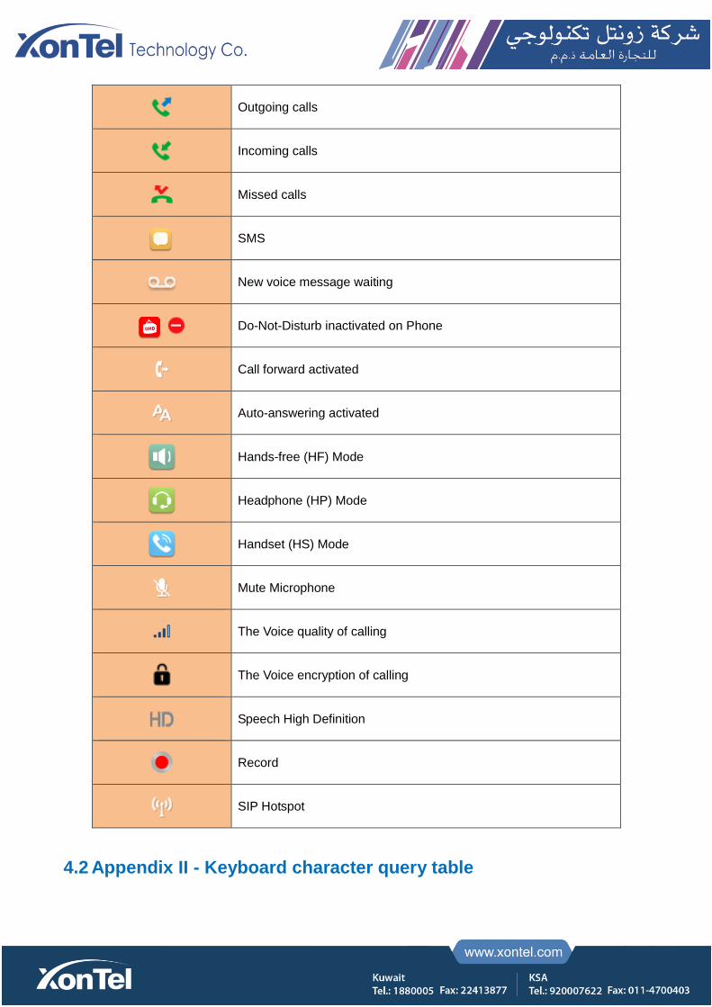
Outgoing calls
Incoming calls
Missed calls
SMS
New voice message waiting
Do-Not-Disturb inactivated on Phone
Call forward activated
Auto-answering activated
Hands-free (HF) Mode
Headphone (HP) Mode
Handset (HS) Mode
Mute Microphone
The Voice quality of calling
The Voice encryption of calling
Speech High Definition
Record
SIP Hotspot
4.2 Appendix II - Keyboard character query table
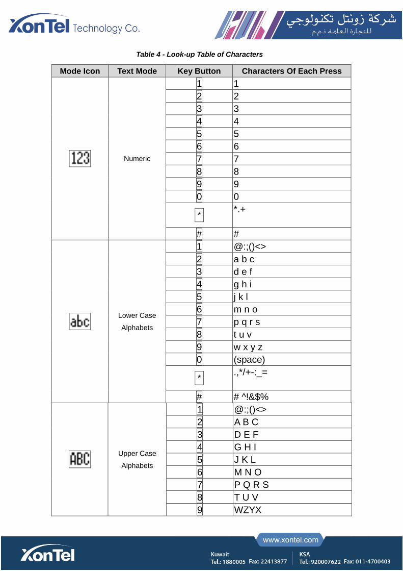
Table 4 - Look-up Table of Characters
Mode Icon Text Mode Key Button Characters Of Each Press
Numeric
1 1
2 2
3 3
4 4
5 5
6 6
7 7
8 8
9 9
0 0
* *.+
# #
Lower Case
Alphabets
1 @:;()<>
2 a b c
3 d e f
4 g h i
5 j k l
6 m n o
7 p q r s
8 t u v
9 w x y z
0 (space)
* .,*/+-:_=
# # ^!&$%
Upper Case
Alphabets
1 @:;()<>
2 A B C
3 D E F
4 G H I
5 J K L
6 M N O
7 P Q R S
8 T U V
9 WZYX

0 (space)
* .,*/+-:_=
# # ^!&$%
Mixed type input
1 1
2 2 a b c A B C
3 3 d e f D E F
4 4 g h I G H I
5 5 j k l J K L
6 6 m n o M N O
7 7 p q r s P Q R S
8 8 t u v T U V
9 9 w z y x W Z Y X
0 0
* .,*/+-:_=
# # ^!&$%

4.3 Appendix III –LED Definition
Table 5 - DSS KEY LED State
Type LED Light State
Line Key
Off Line inactive
Green On Line ready (Registered)
Green Blinking Ringing
Red Blinking Line is trying to register
Red Blinking Line error (Registration failure)
Red On Dialing/Line in use (Talking)
Yellow Blinking Call holding
BLF
Green On Subscription number is idle.
Red On Subscription number is busy.
Red On Subscription number is dialing.
Off Subscription number is unavailable.
Presence
Green On Subscription number is idle.
Red On Subscription number is busy.
Red On Subscription number is dialing.
Off Subscription number is unavailable.
DND Red On Enable DND
Off Disable DND
MWI Green Blinking New voice message waiting
Off No new voice message

5 Introduction to the User
5.1 Instruction of Keypad
Picture 4 - Instruction of Keypad
The picture above shows the keypad layout of the phone. Each button provides its own specific function.
Users can refer to the instructions for the keys in the illustration in this section to operate the phone.
Table 6 - Instruction of Keypad
Number The keypad names Instruction
○1 Soft-menu Buttons These four buttons provide different functions corresponding to the soft-menu
displayed on the screen.
○2 Contact Key Press the "Contact" key, the user can enter the address book interface and
select the contact person to call.
○3 MWI Press the "voice mail" button, and the user enters the interface of SMS and
voice mail list.

○4 Navigate/OK Keys
The user can press the up/down navigation key to change the line or move the
cursor in the screen list. On some Settings and text editing pages, the user can
press the left/right navigation key to change options or move the cursor in the
screen list to the left/right.
OK key: Default is equivalent to soft button confirmation, user can customize
the function.
○5 Line key Default to line 1/ line 2, support the custom configuration of DSS key.
○6 Volume Up/Down Key
In the standby state of ringing and the ringing configuration interface, press this
button to increase/reduce the ring volume; Press this button to increase/lower
the volume on the call or volume adjustment screen.
○7 Mute Key During a call, the user can press this key to mute the microphone.
○8 Standard Telephone
Keys
The 12 standard telephone keys provide the same function as standard
telephones, but further to the standard function, some keys also provide
special function by long-pressing the key,
Key # - Long-pressed to lock the phone.
○9 Headset Key Users can press this key to open the headset channel
○10 Redial Press the Redial key to redial the last number dialed
○11 Hands-free Key The user can press this key to open the speakerphone.
5.2 Using Handset / Hands-free Speaker / Headphone
Using Handset
To talk over handset, user should lift the handset off the device and dial the number, or dial the number first,
then lift the handset and the number will be dialed. User can switch audio channel to handset by lifting the
handset when audio channel is turned on in speaker or headphone.
Using Hands-free Speaker
To talk over hands-free speaker, user should press the hands-free button then dial the number, or dial the
number first then press the hands-free button. User can switch audio channel to the speaker from handset by
pressing the hands-free button when audio channel is opened in handset.
Using Headphone
To use headphone, by default, user should headset button which is defined by DSS key to turn on the
headphone. Same as handset and hands-free speaker, user can dial the number before or after the
headphone is turned on.
Using Line Keys (Defined by DSS Key)
User can use line key to make or answer a call on specific line. If handset has been lifted, the audio channel
will be opened in handset. Otherwise, the audio channel will be opened in hands-free speaker or headphone.
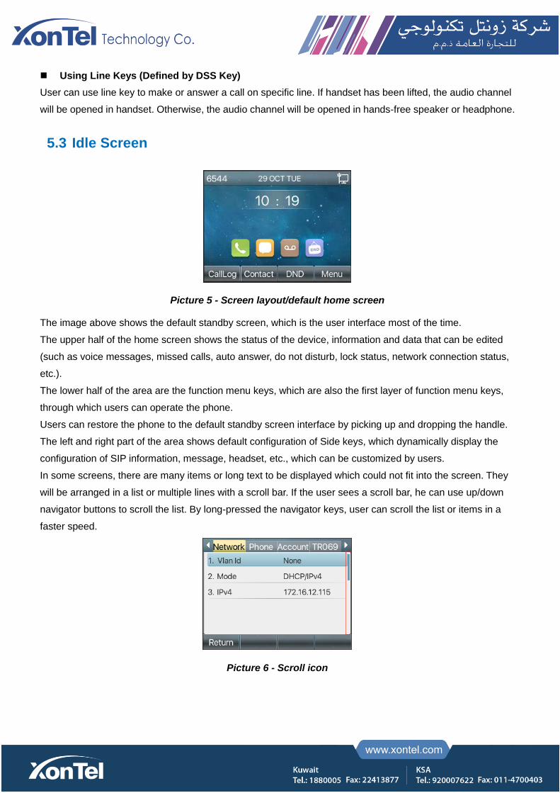
5.3 Idle Screen
Picture 5 - Screen layout/default home screen
The image above shows the default standby screen, which is the user interface most of the time.
The upper half of the home screen shows the status of the device, information and data that can be edited
(such as voice messages, missed calls, auto answer, do not disturb, lock status, network connection status,
etc.).
The lower half of the area are the function menu keys, which are also the first layer of function menu keys,
through which users can operate the phone.
Users can restore the phone to the default standby screen interface by picking up and dropping the handle.
The left and right part of the area shows default configuration of Side keys, which dynamically display the
configuration of SIP information, message, headset, etc., which can be customized by users.
In some screens, there are many items or long text to be displayed which could not fit into the screen. They
will be arranged in a list or multiple lines with a scroll bar. If the user sees a scroll bar, he can use up/down
navigator buttons to scroll the list. By long-pressed the navigator keys, user can scroll the list or items in a
faster speed.
Picture 6 - Scroll icon
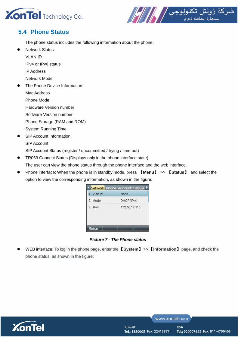
5.4 Phone Status
The phone status includes the following information about the phone:
Network Status:
VLAN ID
IPv4 or IPv6 status
IP Address
Network Mode
The Phone Device Information:
Mac Address
Phone Mode
Hardware Version number
Software Version number
Phone Storage (RAM and ROM)
System Running Time
SIP Account Information:
SIP Account
SIP Account Status (register / uncommitted / trying / time out)
TR069 Connect Status (Displays only in the phone interface state)
The user can view the phone status through the phone interface and the web interface.
Phone interface: When the phone is in standby mode, press 【Menu】 >> 【Status】 and select the
option to view the corresponding information, as shown in the figure:
Picture 7 - The Phone status
WEB interface: To log in the phone page, enter the 【System】 >> 【Information】 page, and check the
phone status, as shown in the figure:
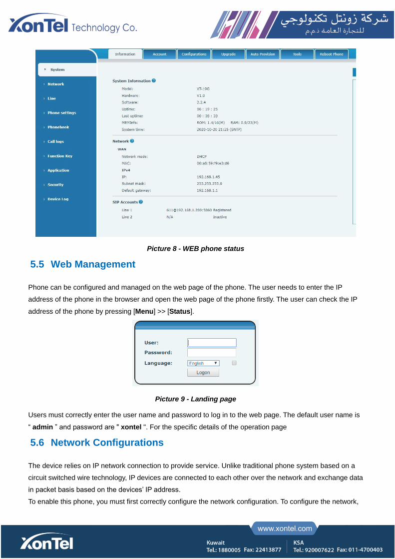
Picture 8 - WEB phone status
5.5 Web Management
Phone can be configured and managed on the web page of the phone. The user needs to enter the IP
address of the phone in the browser and open the web page of the phone firstly. The user can check the IP
address of the phone by pressing [Menu] >> [Status].
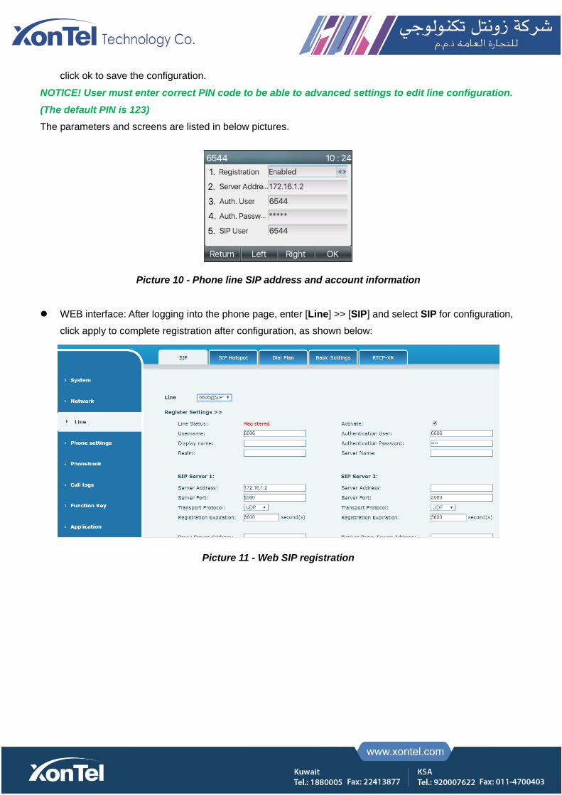
Picture 9 - Landing page
Users must correctly enter the user name and password to log in to the web page. The default user name is
“ admin ” and password are " xontel ". For the specific details of the operation page
5.6 Network Configurations
The device relies on IP network connection to provide service. Unlike traditional phone system based on a
circuit switched wire technology, IP devices are connected to each other over the network and exchange data
in packet basis based on the devices’ IP address.
To enable this phone, you must first correctly configure the network configuration. To configure the network,

users need to find the phone function menu button [Menu] >> [Advanced Settings] >> [Network] >>
[Network].
The default password for advanced Settings is " 123 ".
NOTICE! If user saw a ‘WAN Disconnected’ icon flashing in the middle of screen, it means the
network cable was not correctly connected to the device’s network port. Please check the cable is
connected correctly to the device and to the network switch, router, or modem.
The device supports three types of networks,IPv4/IPv6/IPv4&IPv6
There are three common IP configuration modes about IPv4
Dynamic Host Configuration Protocol (DHCP) – This is the automatic configuration mode by getting
network configurations from a DHCP server. Users don’t need to configure any parameters manually. All
configuration parameters will be getting from DHCP server and applied to the device. This is
recommended for the most users.
Static IP Configuration – This option allows user to configure each IP parameters manually, including IP
Address, Subnet Mask, Default Gateway, and DNS servers. This is usually used in a technical
environment of network users.
PPPoE – This option is often used by users who connect the device to a broadband modem or router. To
establish a PPPoE connection, user should configure username and password provided by the service
provider.
The device is default configured in DHCP mode.
There are three common IP configuration modes about IPv6
DHCP – This is the automatic configuration mode by getting network configurations from a DHCP
server. Users need not to configure any parameters manually. All configuration parameters will be
getting from DHCP server and applied to the device. This is recommended for most users.
Static IP configuration - this option allows users to manually configure each IP parameter, including IP
address, mask, gateway, and primary and secondary domains. This usually applies to some
professional network user environments.
5.7 SIP Configurations
A line must be configured properly to be able to provide telephony service. The line configuration is like a
virtualized SIM card on a mobile phone which stores the service provider and the account information used
for registration and authentication. When the device is applied with the configuration, it will register the device
to the service provider with the server’s address and user’s authentication as stored in the configurations.
The user can conduct line configuration on the interface of the phone or the webpage, and input the
corresponding information at the registered address, registered user name, registered password and SIP
user and registered port respectively, which are provided by the SIP server administrator.
Phone interface: To manually configure a line, the user can press the line key for a long time, or press the
button in the function menu [Menu] >> [Advanced Settings] >> [Accounts] >> [Line n] configuration,
click ok to save the configuration.
NOTICE! User must enter correct PIN code to be able to advanced settings to edit line configuration.
(The default PIN is 123)
The parameters and screens are listed in below pictures.
Picture 10 - Phone line SIP address and account information
WEB interface: After logging into the phone page, enter [Line] >> [SIP] and select SIP for configuration,
click apply to complete registration after configuration, as shown below:
Picture 11 - Web SIP registration
6 Basic Function
6.1 Making Phone Calls
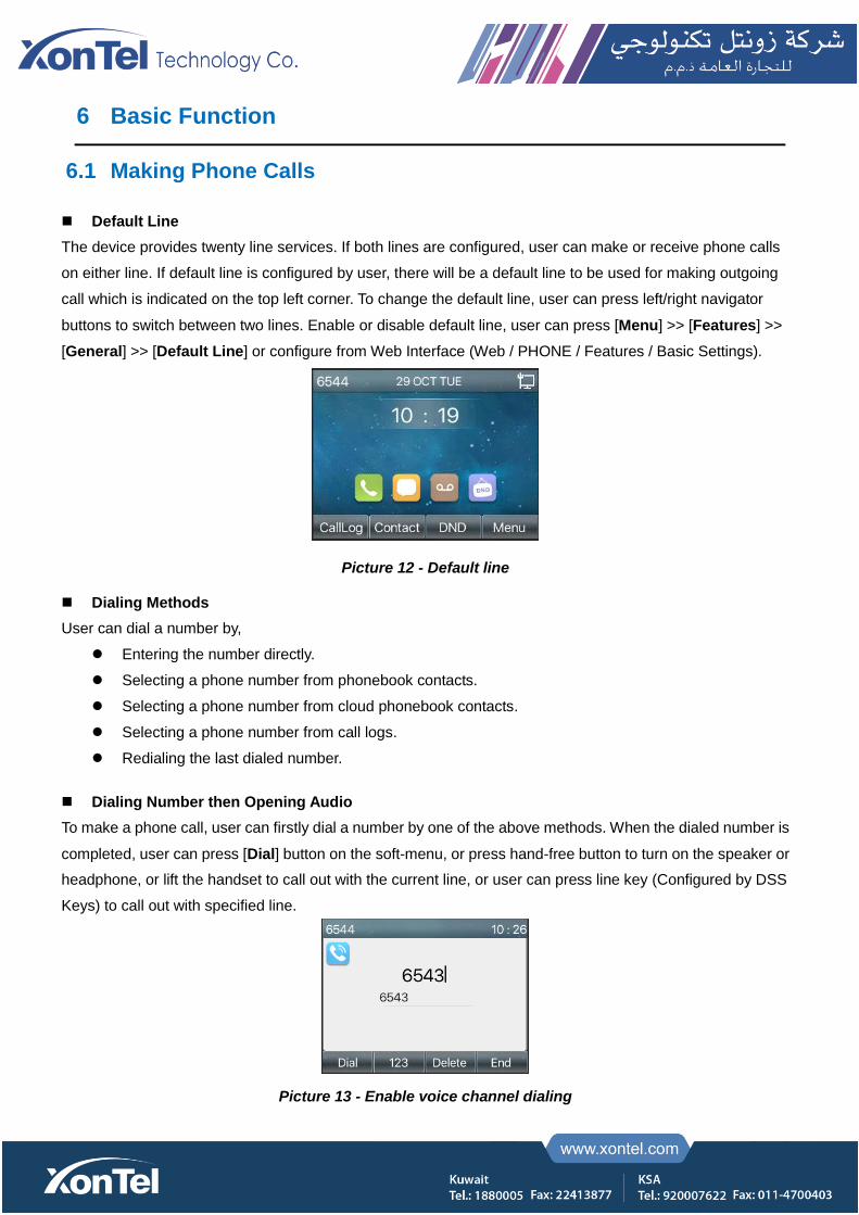
Default Line
The device provides twenty line services. If both lines are configured, user can make or receive phone calls
on either line. If default line is configured by user, there will be a default line to be used for making outgoing
call which is indicated on the top left corner. To change the default line, user can press left/right navigator
buttons to switch between two lines. Enable or disable default line, user can press [Menu] >> [Features] >>
[General] >> [Default Line] or configure from Web Interface (Web / PHONE / Features / Basic Settings).
Picture 12 - Default line
Dialing Methods
User can dial a number by,
Entering the number directly.
Selecting a phone number from phonebook contacts.
Selecting a phone number from cloud phonebook contacts.
Selecting a phone number from call logs.
Redialing the last dialed number.
Dialing Number then Opening Audio
To make a phone call, user can firstly dial a number by one of the above methods. When the dialed number is
completed, user can press [Dial] button on the soft-menu, or press hand-free button to turn on the speaker or
headphone, or lift the handset to call out with the current line, or user can press line key (Configured by DSS
Keys) to call out with specified line.
Picture 13 - Enable voice channel dialing
Opening Audio then Dialing the Number
Another alternative is the traditional way to firstly open the audio channel by lifting the handset, then turn on the
hands-free speaker or headphone by pressing hands-free button, or line key, and then dial the number with one of
the above methods. When completing the number dial, user can press [Dial] button or [OK] button to call out, or
the number can also be dialed out automatically after timeout.
Picture 14 - Open the voice channel and dial the number
Cancel Call
While calling the number, user can stop the audio channel by putting back the handset or pressing the
hands-free button to drop the call.
Picture 15 - Call number
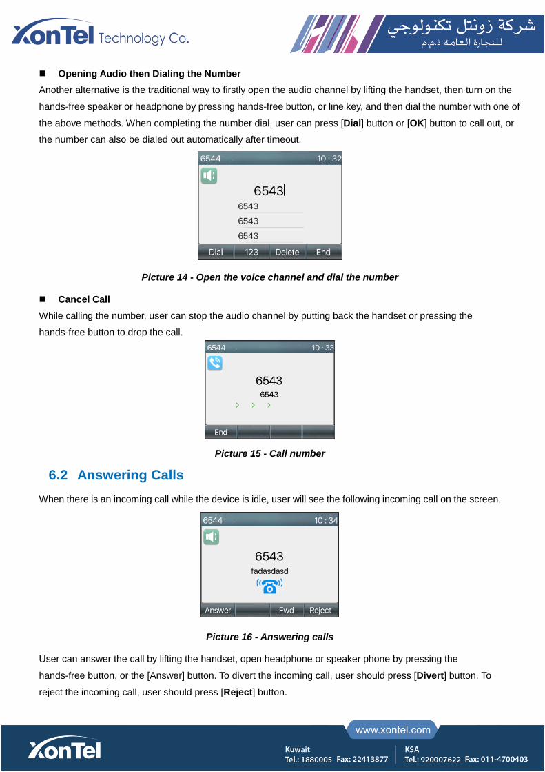
6.2 Answering Calls
When there is an incoming call while the device is idle, user will see the following incoming call on the screen.
Picture 16 - Answering calls
User can answer the call by lifting the handset, open headphone or speaker phone by pressing the
hands-free button, or the [Answer] button. To divert the incoming call, user should press [Divert] button. To
reject the incoming call, user should press [Reject] button.

6.2.1 Talking
When the call is connected, user will see a talking mode screen as the following figure.
Picture 17 - Talking interface
Table 7 - Talking mode
Number Name Description
① Voice channel The icon shows the voice channel mode being used.
② Default line The line currently used by the phone.
③ Calls to end The name or number of the person on the other end of the call.
④ Call duration The duration of a call after it has been established.
⑤ Numbers of line Shows how many calls are present on the current device
⑥ Speech quality Displays the current voice quality of the call.
⑦ HD audio Display HD voice icon when calling using G.722 voice code
6.1.2 Make / Receive Second Call
The device can support up to two concurrent calls. When there is already a call established, user can still
answer another incoming call on either lines or make a second call on either lines.
Second Incoming Call
When there is another incoming call during talking a phone call, this call will be waiting for user to answer.
User will see the call message in the middle of current screen. The device will not be ringing but playing call
waiting tone in the audio channel of the current call and the LED will be flashing in green. User can accept or
reject the call as same as normal incoming call. When the waiting call is answered, the first call will be held on
automatically.
Picture 18 - The second call interface
Second Outgoing Call
To make a second call, user may press [Xfer] / [Conf] button to make a new call on the default line or press
the line key to make new call on specific line. Then dial the number the same way as making a phone call.
Another alternative for making second call is to press DSS Keys or dial out from the configured Keys
(BLF/Speed Dial). When the user is making a second call with the above methods, the first call could be held
on manually or will be held on automatically at second dial.
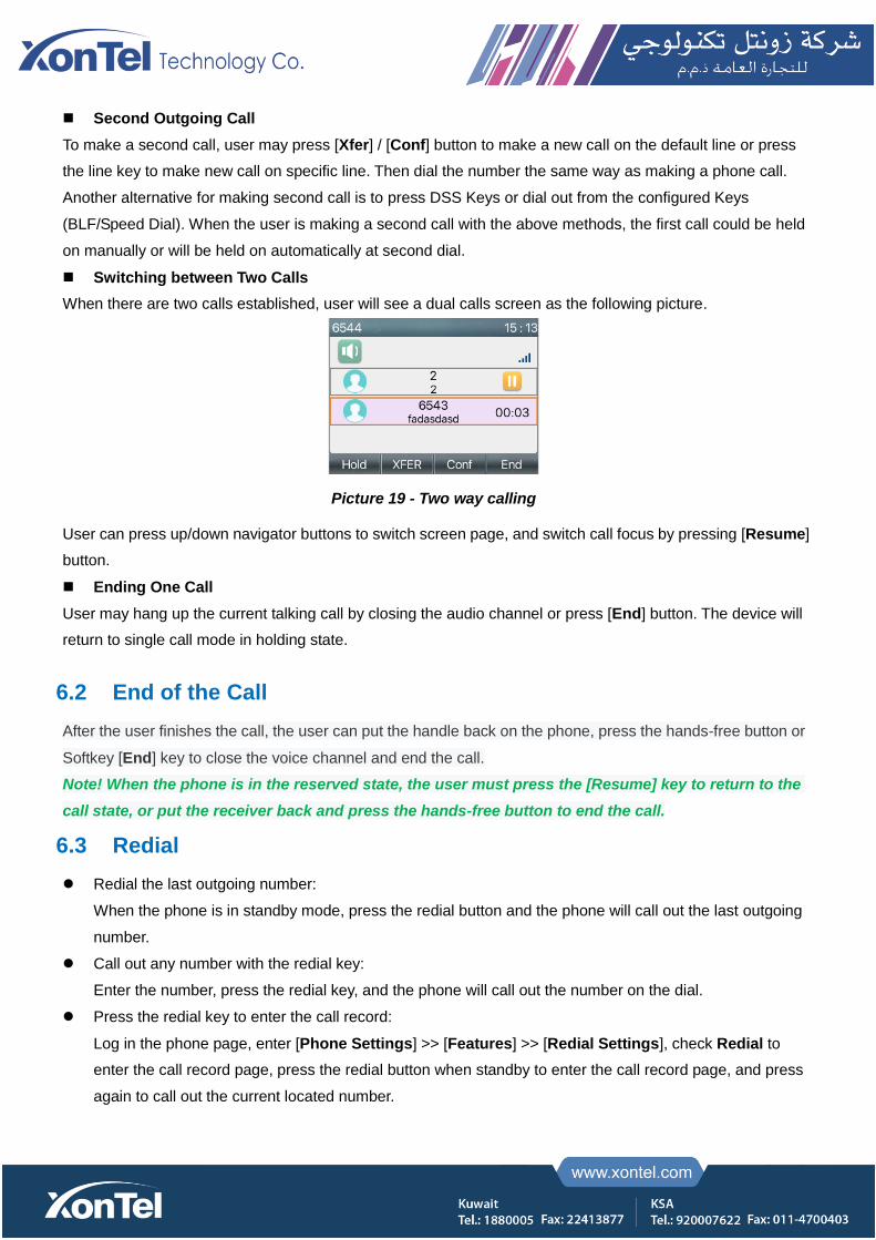
Switching between Two Calls
When there are two calls established, user will see a dual calls screen as the following picture.
Picture 19 - Two way calling
User can press up/down navigator buttons to switch screen page, and switch call focus by pressing [Resume]
button.
Ending One Call
User may hang up the current talking call by closing the audio channel or press [End] button. The device will
return to single call mode in holding state.
6.2 End of the Call
After the user finishes the call, the user can put the handle back on the phone, press the hands-free button or
Softkey [End] key to close the voice channel and end the call.
Note! When the phone is in the reserved state, the user must press the [Resume] key to return to the
call state, or put the receiver back and press the hands-free button to end the call.
6.3 Redial
Redial the last outgoing number:
When the phone is in standby mode, press the redial button and the phone will call out the last outgoing
number.
Call out any number with the redial key:
Enter the number, press the redial key, and the phone will call out the number on the dial.
Press the redial key to enter the call record:
Log in the phone page, enter [Phone Settings] >> [Features] >> [Redial Settings], check Redial to
enter the call record page, press the redial button when standby to enter the call record page, and press
again to call out the current located number.

Picture 20 - Redial set
6.4 Auto-Answering
User may turn on the auto-answering mode on the device and any incoming call will be automatically
answered (not including call waiting). The auto-answering can be enabled on line basis.
The user can start the automatic answer function in the telephone interface or the webpage interface.
Phone interface:
Press [Menu] >> [Features] >> [Auto Answer] button;
Press the button to select the line, use the left/right navigation key to turn on/off the auto answer option, and
set the auto answer time to 5 seconds by default.
After completion, press [OK] key to save;
The icon in the upper right corner of the screen indicates that auto answer is enabled.
Picture 21 - Line 1 enables auto-answering
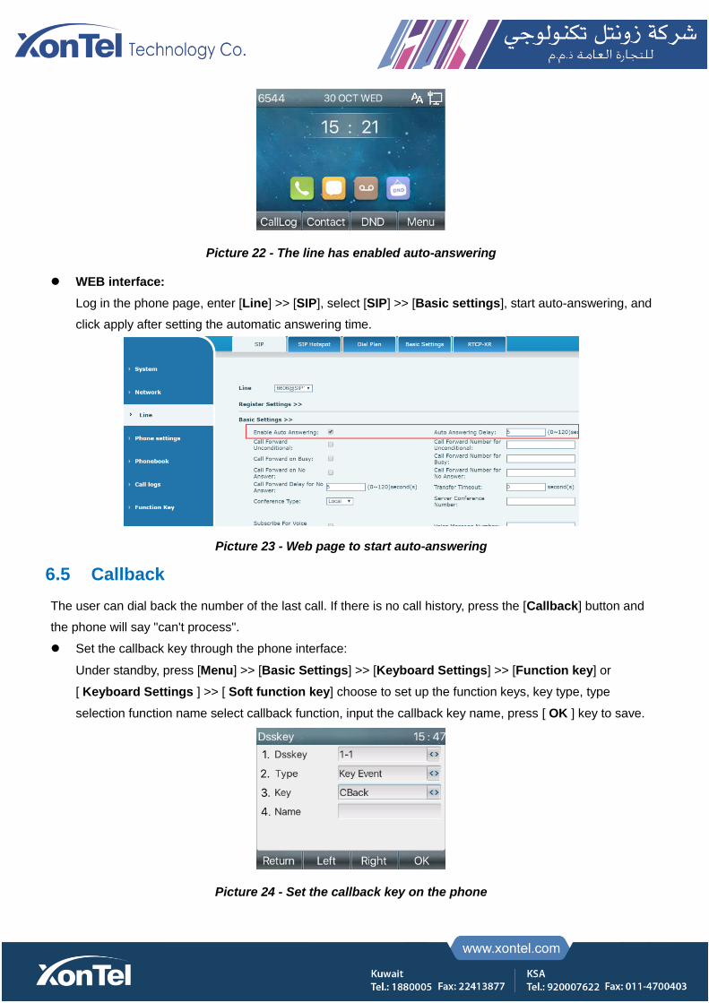
Picture 22 - The line has enabled auto-answering
WEB interface:
Log in the phone page, enter [Line] >> [SIP], select [SIP] >> [Basic settings], start auto-answering, and
click apply after setting the automatic answering time.
Picture 23 - Web page to start auto-answering
6.5 Callback
The user can dial back the number of the last call. If there is no call history, press the [Callback] button and
the phone will say "can't process".
Set the callback key through the phone interface:
Under standby, press [Menu] >> [Basic Settings] >> [Keyboard Settings] >> [Function key] or
[ Keyboard Settings ] >> [ Soft function key] choose to set up the function keys, key type, type
selection function name select callback function, input the callback key name, press [ OK ] key to save.
Picture 24 - Set the callback key on the phone
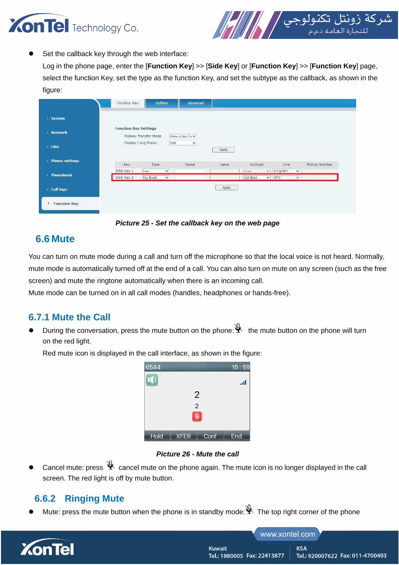
Set the callback key through the web interface:
Log in the phone page, enter the [Function Key] >> [Side Key] or [Function Key] >> [Function Key] page,
select the function Key, set the type as the function Key, and set the subtype as the callback, as shown in the
figure:
Picture 25 - Set the callback key on the web page
6.6 Mute
You can turn on mute mode during a call and turn off the microphone so that the local voice is not heard. Normally,
mute mode is automatically turned off at the end of a call. You can also turn on mute on any screen (such as the free
screen) and mute the ringtone automatically when there is an incoming call.
Mute mode can be turned on in all call modes (handles, headphones or hands-free).
6.7.1 Mute the Call
During the conversation, press the mute button on the phone: the mute button on the phone will turn
on the red light.
Red mute icon is displayed in the call interface, as shown in the figure:
Picture 26 - Mute the call
Cancel mute: press cancel mute on the phone again. The mute icon is no longer displayed in the call
screen. The red light is off by mute button.
6.6.2 Ringing Mute
Mute: press the mute button when the phone is in standby mode: The top right corner of the phone
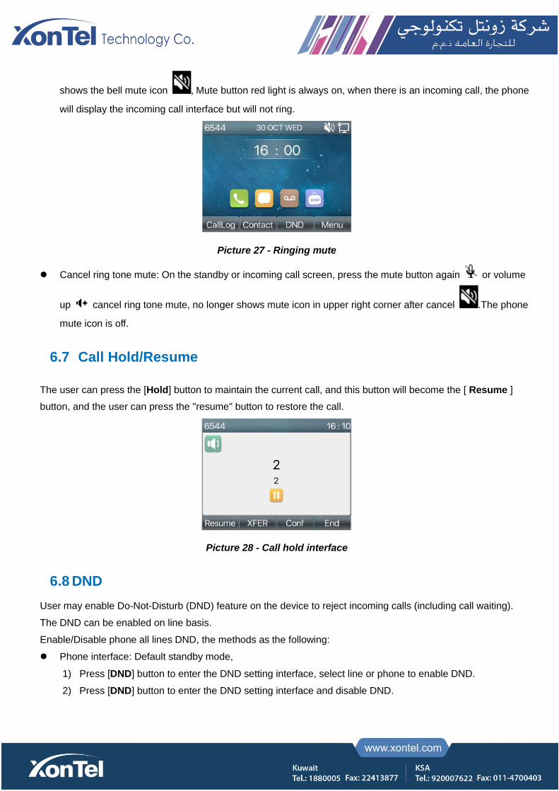
shows the bell mute icon , Mute button red light is always on, when there is an incoming call, the phone
will display the incoming call interface but will not ring.
Picture 27 - Ringing mute
Cancel ring tone mute: On the standby or incoming call screen, press the mute button again or volume
up cancel ring tone mute, no longer shows mute icon in upper right corner after cancel .The phone
mute icon is off.
6.7 Call Hold/Resume
The user can press the [Hold] button to maintain the current call, and this button will become the [ Resume ]
button, and the user can press the "resume" button to restore the call.
Picture 28 - Call hold interface
6.8 DND
User may enable Do-Not-Disturb (DND) feature on the device to reject incoming calls (including call waiting).
The DND can be enabled on line basis.
Enable/Disable phone all lines DND, the methods as the following:
Phone interface: Default standby mode,
1) Press [DND] button to enter the DND setting interface, select line or phone to enable DND.
2) Press [DND] button to enter the DND setting interface and disable DND.
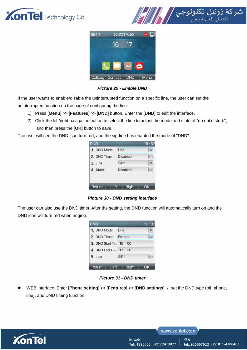
Picture 29 - Enable DND
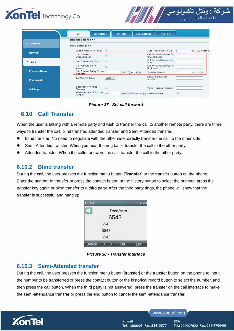
If the user wants to enable/disable the uninterrupted function on a specific line, the user can set the
uninterrupted function on the page of configuring the line.
1) Press [Menu] >> [Features] >> [DND] button, Enter the [DND] to edit the interface.
2) Click the left/right navigation button to select the line to adjust the mode and state of "do not disturb",
and then press the [OK] button to save.
The user will see the DND icon turn red, and the sip-line has enabled the mode of "DND".
Picture 30 - DND setting interface
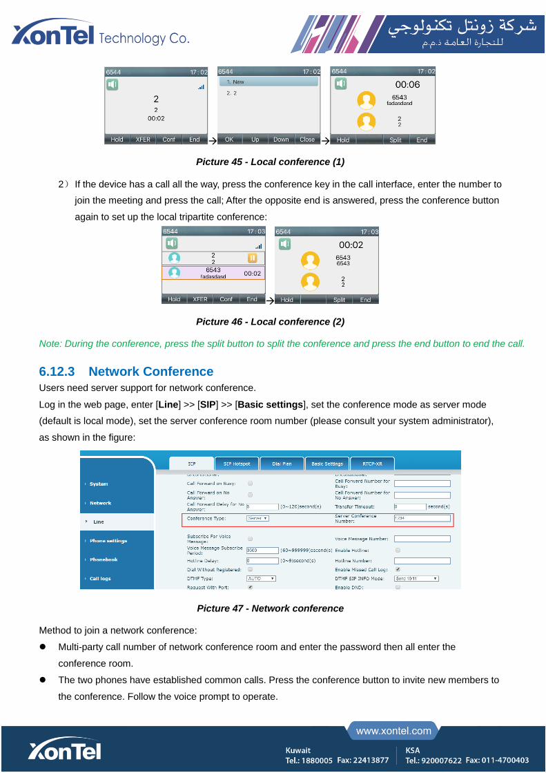
The user can also use the DND timer. After the setting, the DND function will automatically turn on and the
DND icon will turn red when ringing.
Picture 31 - DND timer
WEB interface: Enter [Phone setting] >> [Features] >> [DND settings] ,set the DND type (off, phone,
line), and DND timing function.

Picture 32 - DND Settings
The user turns on the DND for a specific route on the web page: Enter [Line] >> [SIP], select a [Line] >>
[Basic settings], and enable DND.
Picture 33 - Line DND
6.9 Call Forward
Call forward is also known as ‘Call Divert’ which is to divert the incoming call to a specific number based on
the conditions and configurations. User can configure the call forward settings of each line.
There are three types.
Unconditional Call Forward – Forward any incoming call to the configured number.
Call Forward on Busy – When user is busy, the incoming call will be forwarded to the configured
number.
Call Forward on No Answer – When user does not answer the incoming call after the configured delay
time, the incoming call will be forwarded to the configured number.
Phone interface: Default standby mode
1) Press [Menu] >> [Features] >> [Call Forward] button, select the line by up/down navigation key,
press [OK] button to set call forward.

Picture 34 - Select the line to set up call forwarding
2) Select the call forward type by pressing the up/down navigation button. Click [OK] to configure call
forwarding and delay time.
Picture 35 - Select call forward type
3) Select enable/disable by pressing the left/right navigation button.
Picture 36 - Enable call forwarding and configure the call forwarding number
4) Browse the parameters set by the up/down navigation key and enter the required information. When
finished, press the [OK] button to save the changes.
WEB interface: Enter [Line] >> [SIP], Select a [Line] >> [Basic settings], and set the type, number and
time of forward forwarding.
Picture 37 - Set call forward
6.10 Call Transfer
When the user is talking with a remote party and wish to transfer the call to another remote party, there are three
ways to transfer the call, blind transfer, attended transfer and Semi-Attended transfer.
Blind transfer: No need to negotiate with the other side, directly transfer the call to the other side.
Semi-Attended transfer: When you hear the ring back, transfer the call to the other party.
Attended transfer: When the caller answers the call, transfer the call to the other party.
6.10.2 Blind transfer
During the call, the user presses the function menu button [Transfer] or the transfer button on the phone,
Enter the number to transfer or press the contact button or the history button to select the number, press the
transfer key again or blind transfer to a third party. After the third party rings, the phone will show that the
transfer is successful and hang up.
Picture 38 - Transfer interface
6.10.3 Semi-Attended transfer
During the call, the user presses the function menu button [transfer] or the transfer button on the phone to input
the number to be transferred or press the contact button or the historical record button to select the number, and
then press the call button. When the third party is not answered, press the transfer on the call interface to make
the semi-attendance transfer or press the end button to cancel the semi-attendance transfer.

Picture 39 - Semi-Attended transfer
6.10.4 Attended transfer
Attendance transfer is also known as "courtesy mode", which is to transfer the call by calling the other party
and waiting for the other party to answer the call.
The same procedure to calling. In dual call mode, press the "transfer" button to transfer the first call to the second call.
Picture 40 - Attended transfer
6.11 Call Waiting
Enable call waiting: new calls can be accepted during a call.
Disable call waiting: new calls will be automatically rejected and a busy tone will be prompted.
Enable call waiting tone: when you receive a new call on the line, the tone will beep.
The user can enable/disable the call waiting function in the phone interface and the web interface.
Phone interface: Press [Menu] >> [Features] >> [Call waiting], the navigation key and left/right button
enable/disable call waiting and call waiting tone. Press [Menu] >> [Features] >> [Call waiting], the
navigation key and left/right button enable/disable call waiting and call waiting tone.
Picture 41 - Call waiting setting

WEB interface: Enter [Phone Settings] >> [Features] >> [Basic Settings], enable/disable call waiting
and call waiting tone.
Picture 42 - Web call waiting setting
Picture 43 - Web call waiting tone setting
6.12 Conference
6.12.2 Local Conference
To conduct local conference, the user needs to log in the webpage and enter [Line] >> [SIP] >> [Basic
settings]. The meeting mode is set as local (the default is local mode), as shown in the figure:
Picture 44 - Local conference setting
Two ways to create a local conference:
1) The device has two channels of communication. Press the conference button on the call interface.
When selecting the conference number, select the other number that already exists.
Picture 45 - Local conference (1)
2) If the device has a call all the way, press the conference key in the call interface, enter the number to
join the meeting and press the call; After the opposite end is answered, press the conference button
again to set up the local tripartite conference:
Picture 46 - Local conference (2)
Note: During the conference, press the split button to split the conference and press the end button to end the call.
6.12.3 Network Conference
Users need server support for network conference.
Log in the web page, enter [Line] >> [SIP] >> [Basic settings], set the conference mode as server mode
(default is local mode), set the server conference room number (please consult your system administrator),
as shown in the figure:
Picture 47 - Network conference
Method to join a network conference:
Multi-party call number of network conference room and enter the password then all enter the
conference room.
The two phones have established common calls. Press the conference button to invite new members to
the conference. Follow the voice prompt to operate.

Note: the upper limit of the number of participants in the network conference varies according to the server.
6.13 Call Park
Call park requires server support. Consult your system administrator for support.
When you are on the call, if it is not convenient to answer the phone at this time, you can press the configured
park button to hold the call; After a successful park, you can resume the call by pressing the configured park
button on other devices.
Set the call park button:
Phone interface: long press a function key to enter the function key Settings interface, or through the
[Menu] >> [Basic Settings] >> [Keyboard Settings] enter the settings interface of function keys, and
set the key function type as memory and subtypes as call park, reside values for the server calls park
number, set up corresponding SIP lines.
WEB interface: log in the phone page, enter the [Function Key] >> [Function Key] page, select a
DSSkey, set the function key type as memory key, the subtype as call park, and the value as the call park
number of the server, and set the corresponding SIP line.
Picture 48 - Phone set call park
Picture 49 - WEB set call park
6.14 Pick Up
Pick up requires server support. Consult your system administrator for support.
You can use the Pick Up function to answer incoming calls from other users. The phone can pick up incoming
calls by configuring DSS key for BLF and setting the Pick Up code.
Phone interface: press [Menu] >> [Basic Settings] >> [Keyboard Settings] >> [DSS Key Settings], select
the function key to set.
Set the line, function key type as memory key, subtype as BLF/NEW CALL, set subscription number, and
pick up code
Other phones call the subscription number, and the opposite end is in the incoming ring.
Press the DSS key to pick up the phone.
The caller picks up the call and speaks to it.
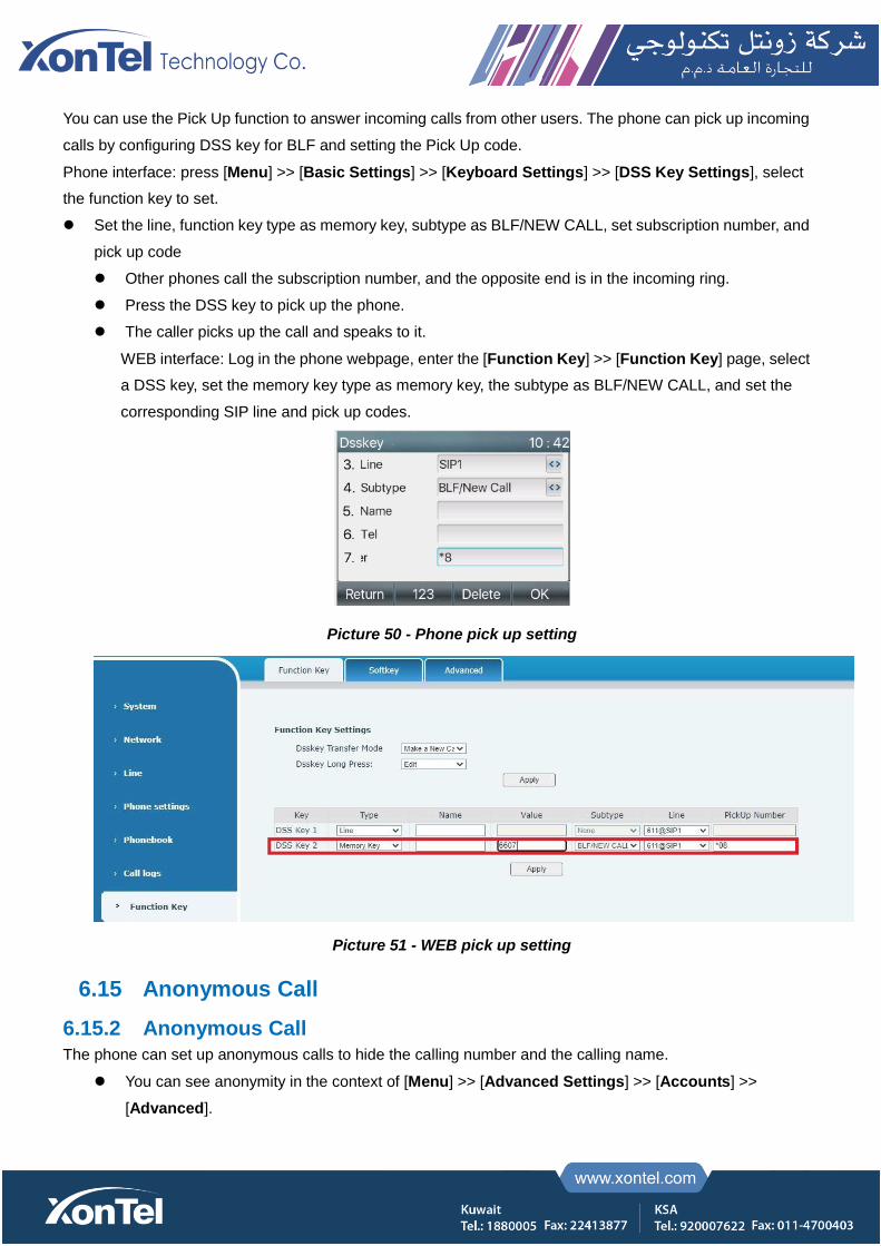
WEB interface: Log in the phone webpage, enter the [Function Key] >> [Function Key] page, select
a DSS key, set the memory key type as memory key, the subtype as BLF/NEW CALL, and set the
corresponding SIP line and pick up codes.
Picture 50 - Phone pick up setting
Picture 51 - WEB pick up setting
6.15 Anonymous Call
6.15.2 Anonymous Call
The phone can set up anonymous calls to hide the calling number and the calling name.
You can see anonymity in the context of [Menu] >> [Advanced Settings] >> [Accounts] >>
[Advanced].

The default is none, which is off, and RFC3323 and RFC3325 are optional.
Select any one to open the anonymous call.
Picture 52 - Enable anonymous call
On the web page [Line] >> [SIP] >> [Advanced Settings] can also open the mode of anonymous
calls.
Setting to enable anonymous calls also corresponds to the SIP line. That is, the setting under the
SIP1 page can only take effect on the SIP1 line.
Picture 53 - Enable Anonymous web page call
The following is a transcript of an anonymous call received by the phone.
Picture 54 - Anonymous call log
6.15.3 Ban Anonymous Call
The device can be set to prohibit anonymous calls, that is anonymous calls to the number will be directly rejected.
In the phone [Menu] >> [Features] >> [Ban anonymous call], click to enter and all SIP lines will be displayed.
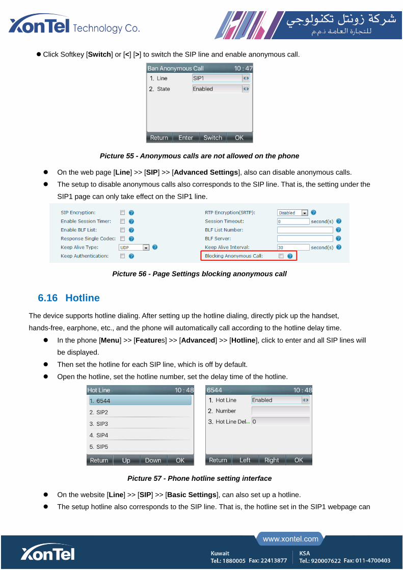
Click Softkey [Switch] or [<] [>] to switch the SIP line and enable anonymous call.
Picture 55 - Anonymous calls are not allowed on the phone
On the web page [Line] >> [SIP] >> [Advanced Settings], also can disable anonymous calls.
The setup to disable anonymous calls also corresponds to the SIP line. That is, the setting under the
SIP1 page can only take effect on the SIP1 line.
Picture 56 - Page Settings blocking anonymous call
6.16 Hotline
The device supports hotline dialing. After setting up the hotline dialing, directly pick up the handset,
hands-free, earphone, etc., and the phone will automatically call according to the hotline delay time.
In the phone [Menu] >> [Features] >> [Advanced] >> [Hotline], click to enter and all SIP lines will
be displayed.
Then set the hotline for each SIP line, which is off by default.
Open the hotline, set the hotline number, set the delay time of the hotline.
Picture 57 - Phone hotline setting interface
On the website [Line] >> [SIP] >> [Basic Settings], can also set up a hotline.
The setup hotline also corresponds to the SIP line. That is, the hotline set in the SIP1 webpage can
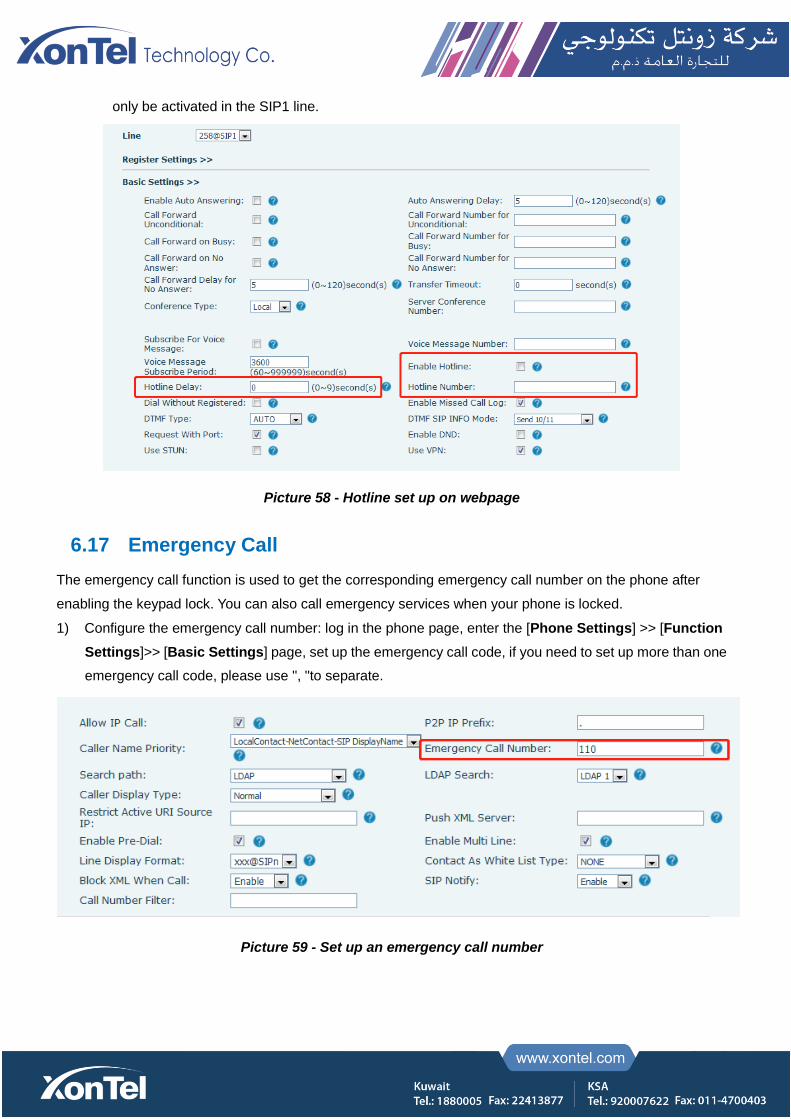
only be activated in the SIP1 line.
Picture 58 - Hotline set up on webpage
6.17 Emergency Call
The emergency call function is used to get the corresponding emergency call number on the phone after
enabling the keypad lock. You can also call emergency services when your phone is locked.
1) Configure the emergency call number: log in the phone page, enter the [Phone Settings] >> [Function
Settings]>> [Basic Settings] page, set up the emergency call code, if you need to set up more than one
emergency call code, please use ", "to separate.
Picture 59 - Set up an emergency call number
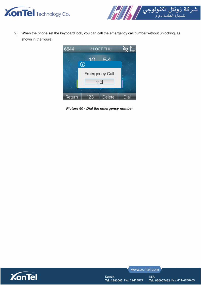
2) When the phone set the keyboard lock, you can call the emergency call number without unlocking, as
shown in the figure:
Picture 60 - Dial the emergency number
7 Advance Function
7.1 BLF (Busy Lamp Field)
7.1.1 Configure the BLF Functionality
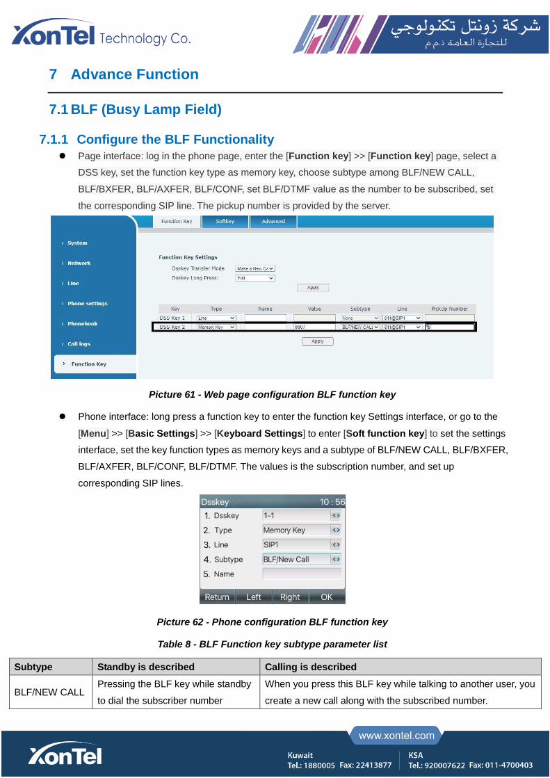
Page interface: log in the phone page, enter the [Function key] >> [Function key] page, select a
DSS key, set the function key type as memory key, choose subtype among BLF/NEW CALL,
BLF/BXFER, BLF/AXFER, BLF/CONF, set BLF/DTMF value as the number to be subscribed, set
the corresponding SIP line. The pickup number is provided by the server.
Picture 61 - Web page configuration BLF function key
Phone interface: long press a function key to enter the function key Settings interface, or go to the
[Menu] >> [Basic Settings] >> [Keyboard Settings] to enter [Soft function key] to set the settings
interface, set the key function types as memory keys and a subtype of BLF/NEW CALL, BLF/BXFER,
BLF/AXFER, BLF/CONF, BLF/DTMF. The values is the subscription number, and set up
corresponding SIP lines.
Picture 62 - Phone configuration BLF function key
Table 8 - BLF Function key subtype parameter list
Subtype Standby is described Calling is described
BLF/NEW CALL Pressing the BLF key while standby
to dial the subscriber number
When you press this BLF key while talking to another user, you
create a new call along with the subscribed number.
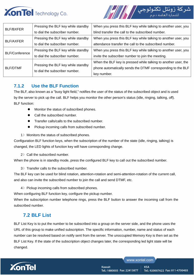
BLF/BXFER Pressing the BLF key while standby
to dial the subscriber number.
When you press this BLF key while talking to another user, you
blind transfer the call to the subscribed number.
BLF/AXFER Pressing the BLF key while standby
to dial the subscriber number.
When you press this BLF key while talking to another user, you
attendance transfer the call to the subscribed number.
BLF/Conference Pressing the BLF key while standby
to dial the subscriber number.
When you press this BLF key while talking to another user, you
invite the subscriber number to join the meeting.
BLF/DTMF Pressing the BLF key while standby
to dial the subscriber number.
When the BLF key is pressed while talking to another user, the
phone automatically sends the DTMF corresponding to the BLF
key number.
7.1.2 Use the BLF Function
The BLF, also known as a "busy light field," notifies the user of the status of the subscribed object and is used
by the server to pick up the call. BLF helps you monitor the other person's status (idle, ringing, talking, off).
BLF function:
Monitor the status of subscribed phones.
Call the subscribed number.
Transfer calls/calls to the subscribed number.
Pickup incoming calls from subscribed number.
1) Monitors the status of subscribed phones.
Configuration BLF function keys, when the subscription of the number of the state (idle, ringing, talking) is
changed, the LED lights of function key will have corresponding change.
2) Call the subscribed number.
When the phone is in standby mode, press the configured BLF key to call out the subscribed number.
3) Transfer calls to the subscribed number.
The BLF key can be used for blind rotation, attention-rotation and semi-attention-rotation of the current call,
and also can invite the subscribed number to join the call and send DTMF, etc.
4) Pickup incoming calls from subscribed phones.
When configuring BLF function key, configure the pickup number.
When the subscription number telephone rings, press the BLF button to answer the incoming call from the
subscribed number.
7.2 BLF List
BLF List Key is to put the number to be subscribed into a group on the server side, and the phone uses the
URL of this group to make unified subscription. The specific information, number, name and status of each
number can be resolved based on notify sent from the server. The unoccupied Memory Key is then set as the
BLF List Key. If the state of the subscription object changes later, the corresponding led light state will be
changed.
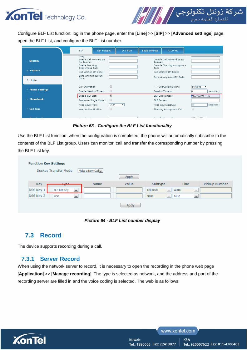
Configure BLF List function: log in the phone page, enter the [Line] >> [SIP] >> [Advanced settings] page,
open the BLF List, and configure the BLF List number.
Picture 63 - Configure the BLF List functionality
Use the BLF List function: when the configuration is completed, the phone will automatically subscribe to the
contents of the BLF List group. Users can monitor, call and transfer the corresponding number by pressing
the BLF List key.
Picture 64 - BLF List number display
7.3 Record
The device supports recording during a call.
7.3.1 Server Record
When using the network server to record, it is necessary to open the recording in the phone web page
[Application] >> [Manage recording]. The type is selected as network, and the address and port of the
recording server are filled in and the voice coding is selected. The web is as follows:
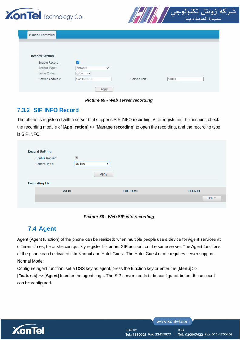
Picture 65 - Web server recording
7.3.2 SIP INFO Record
The phone is registered with a server that supports SIP INFO recording. After registering the account, check
the recording module of [Application] >> [Manage recording] to open the recording, and the recording type
is SIP INFO.
Picture 66 - Web SIP info recording
7.4 Agent
Agent (Agent function) of the phone can be realized: when multiple people use a device for Agent services at
different times, he or she can quickly register his or her SIP account on the same server. The Agent functions
of the phone can be divided into Normal and Hotel Guest. The Hotel Guest mode requires server support.
Normal Mode:
Configure agent function: set a DSS key as agent, press the function key or enter the [Menu] >>
[Features] >> [Agent] to enter the agent page. The SIP server needs to be configured before the account
can be configured.
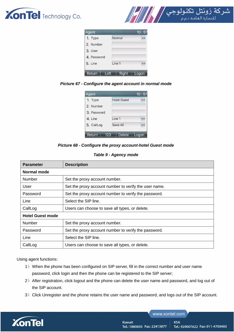
Picture 67 - Configure the agent account in normal mode
Picture 68 - Configure the proxy account-hotel Guest mode
Table 9 - Agency mode
Parameter Description
Normal mode
Number Set the proxy account number.
User Set the proxy account number to verify the user name.
Password Set the proxy account number to verify the password.
Line Select the SIP line.
CallLog Users can choose to save all types, or delete.
Hotel Guest mode
Number Set the proxy account number.
Password Set the proxy account number to verify the password.
Line Select the SIP line.
CallLog Users can choose to save all types, or delete.
Using agent functions:
1) When the phone has been configured on SIP server, fill in the correct number and user name
password, click login and then the phone can be registered to the SIP server;
2) After registration, click logout and the phone can delete the user name and password, and log out of
the SIP account.
3) Click Unregister and the phone retains the user name and password, and logs out of the SIP account.

Picture 69 - Agent logon page
7.5 Intercom
When the Intercom is enabled, it can automatically receive calls from the intercom.
Picture 70 - Web Intercom configure
Table 10 - Intercom configure
Parameter Description
Enable Intercom When intercom is enabled, the device will accept the incoming call request with a SIP
header of Alert-Info instruction to automatically answer the call after specific delay.
Enable Intercom Mute Enable mute mode during the intercom call
Enable Intercom Tone If the incoming call is intercom call, the phone plays the intercom tone
Enable Intercom Barge Enable Intercom Barge by selecting it, the phone auto answers the intercom call during
a call. If the current call is intercom call, the phone will reject the second intercom call
7.6 MCAST
This feature allows user to make some kind of broadcast call to people who are in multicast group. User can
configure a multicast DSS Key on the phone, which allows user to send a Real Time Transport Protocol (RTP)
stream to the pre-configured multicast address without involving SIP signaling. You can also configure the phone
to receive an RTP stream from pre-configured multicast listening address without involving SIP signaling. You
can specify up to 10 multicast listening addresses.
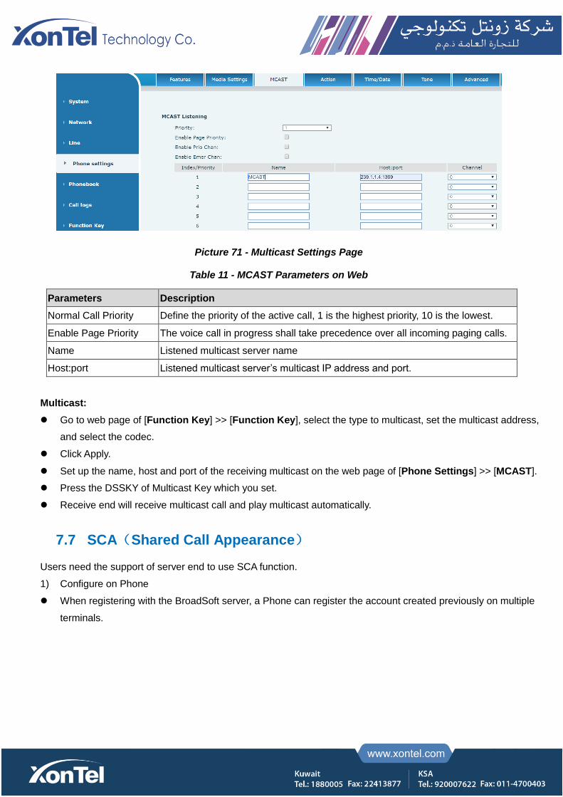
Picture 71 - Multicast Settings Page
Table 11 - MCAST Parameters on Web
Parameters Description
Normal Call Priority Define the priority of the active call, 1 is the highest priority, 10 is the lowest.
Enable Page Priority The voice call in progress shall take precedence over all incoming paging calls.
Name Listened multicast server name
Host:port Listened multicast server’s multicast IP address and port.
Multicast:
Go to web page of [Function Key] >> [Function Key], select the type to multicast, set the multicast address,
and select the codec.
Click Apply.
Set up the name, host and port of the receiving multicast on the web page of [Phone Settings] >> [MCAST].
Press the DSSKY of Multicast Key which you set.
Receive end will receive multicast call and play multicast automatically.
7.7 SCA(Shared Call Appearance)
Users need the support of server end to use SCA function.
1) Configure on Phone
When registering with the BroadSoft server, a Phone can register the account created previously on multiple
terminals.

Picture 72 - Register BroadSoft account
After the phone set registers with the BroadSoft server, a server type needs to be set. Specifically, log in
to the webpage of the phone set, choose [Line] >> [SIP] >> [Advanced Settings] and set Specific
Server Type to BroadSoft, as shown in the following figure.
Picture 73 - Set BroadSoft server
If a ip phone needs to enable the SCA function. Specifically, log in to the webpage of the phone set,
choose [Line] >> [SIP] >> [Advanced Settings], and select Enable SCA. If SCA is not enabled, the
registered line is the private line.
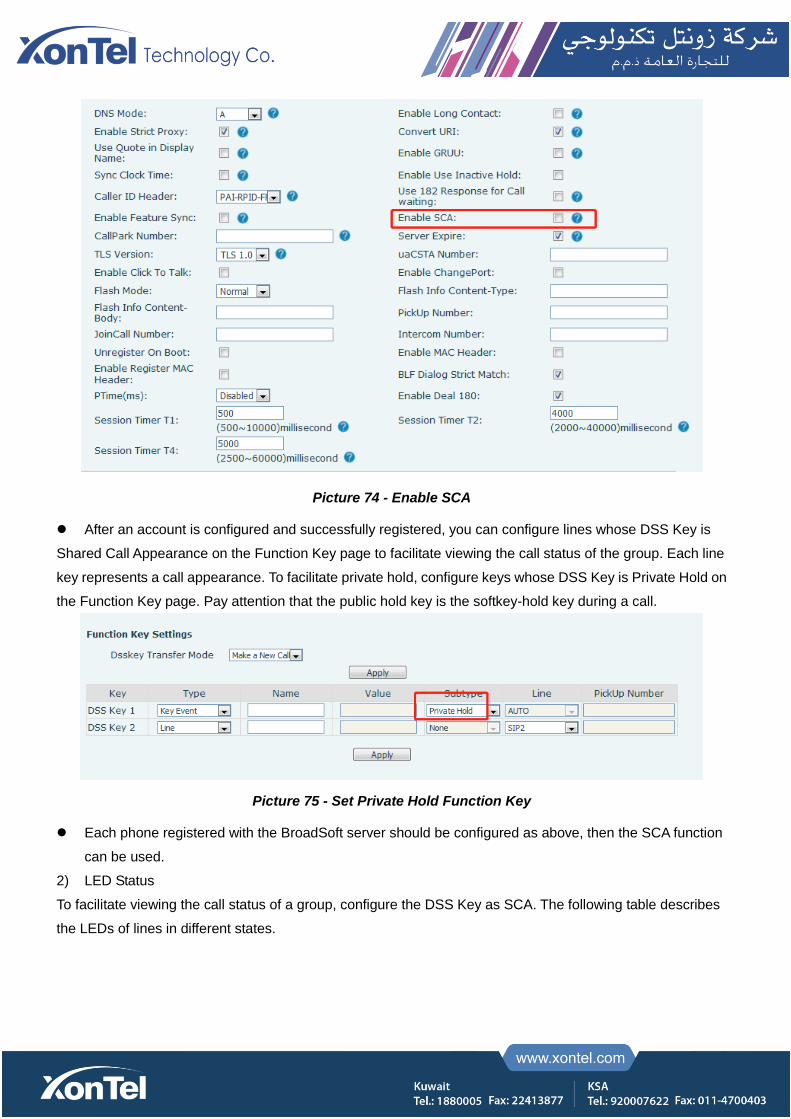
Picture 74 - Enable SCA
After an account is configured and successfully registered, you can configure lines whose DSS Key is
Shared Call Appearance on the Function Key page to facilitate viewing the call status of the group. Each line
key represents a call appearance. To facilitate private hold, configure keys whose DSS Key is Private Hold on
the Function Key page. Pay attention that the public hold key is the softkey-hold key during a call.
Picture 75 - Set Private Hold Function Key
Each phone registered with the BroadSoft server should be configured as above, then the SCA function
can be used.
2) LED Status
To facilitate viewing the call status of a group, configure the DSS Key as SCA. The following table describes
the LEDs of lines in different states.

Table 12 - LED Status of SCA
State & Direction Local Remote
Idle Off Off
Seized Steady White Steady red
Progressing (outgoing call) Steady White Steady red
Alerting (incoming call) Fast blinking White Fast blinking White
Active Steady White Steady red
Public Held (hold) Slow blinking White Slow blinking red
Held-private (private hold) Slow blinking yellow Steady red
Bridge-active (Barge-in) Steady White Steady red
Bridge-held Steady White Steady red
3) Shared Call Appearance(SCA)
The following lists a couple of instances to facilitate understanding.
In the following scenarios, the manager and secretary register the same SCA account and the account is
configured based on the preceding steps.
Scenario 1: When this account receives an incoming call, the phone sets of both the manager and the secretary
will receive the call and ring. If the manager is busy, the manager can reject the call and the manager's phone set
stops ringing but the secretary's phone set keeps ringing until the secretary rejects/answers the call or the call
times out.
Scenario 2: When this account receives an incoming call, if the secretary answers the call first and the manager is
required to answer the call, the secretary can press the Public Hold key to hold this call and notify the manager.
The manager can press the line key corresponding to the SCA to answer the call.
Scenario 3: The manager is in an important call with a customer and needs to leave for a while. If the manager
does not want others to retrieve this call, the manager can press the Private Hold key.
Scenario 4: The manager is in a call with a customer and requires the secretary to join the call to make records.
The secretary can press the corresponding SCA line key to barge in this call.
7.8 Message
7.8.1 SMS
If the service of the line supports the function of the short message, when the other end sends a text message to
the number, the user will receive the notification of the short message and display the icon of the new SMS on the
standby screen interface.

Picture 76 - SMS icon
Send messages:
Go to [Menu] >> [Message] >> [SMS].
Users can create new messages, select lines and send numbers.
After editing is completed, click Send.
View SMS:
Use the navigation keys to select the standby icon [message]
After selecting, press the navigation key [OK] to enter the SMS inbox interface.
Select the unread message and press [OK] to read the unread message.
Reply to SMS:
Use the navigation keys to select the standby icon [Message].
After selecting, press the navigation key [OK] to enter the SMS inbox interface.
Select the message you want to reply to, select Softkey's [Reply], edit it, and click Send.
7.8.2 MWI (Message Waiting Indicator)
If the service of the lines supports voice message feature, when the user is not available to answer the call,
the caller can leave a voice message on the server to the user. User will receive voice message notification
from the server and device will prompt a voice message waiting icon on the standby screen.
Picture 77 - New Voice Message Notification
Voice message icon
To listen to a voice message, the user must first configure the voicemail number. After the voicemail number
is configured, the user can retrieve the voicemail of the default line.

When the phone is in the default standby state,
The Side Key is pre-installed with a voice message shortcut key - [MWI] key.
Press [MWI] to open the voice message configuration interface, and select the line to be configured by
pressing the up/down navigation buttons.
Press the [Edit] button to edit the voice message number. When finished, press the [OK] button to save
the configuration.
In the following picture, “17” in front of the line brackets represents unread voice messages, and “17”
represents the total number of voice messages.
Picture 78 - Voice message interface
Picture 79 - Configure voicemail number
7.9 SIP Hotspot
SIP hotspot is a simple but practical function. With simple configurations, the SIP hotspot function can implement
group ringing. SIP accounts can be expanded.
The users can set functions as a SIP hotspot and other phones set (B and C) function as SIP hotspot clients. When
somebody calls phone set A, phone sets A, B, and C all ring at the same time. When any phone set answers the call,
other phone sets stop ringing. The call can be answered by only one phone set. When B or C initiates a call, the SIP
number registered by phone set A is the calling number.
To set a SIP hotspot, register at least one SIP account.
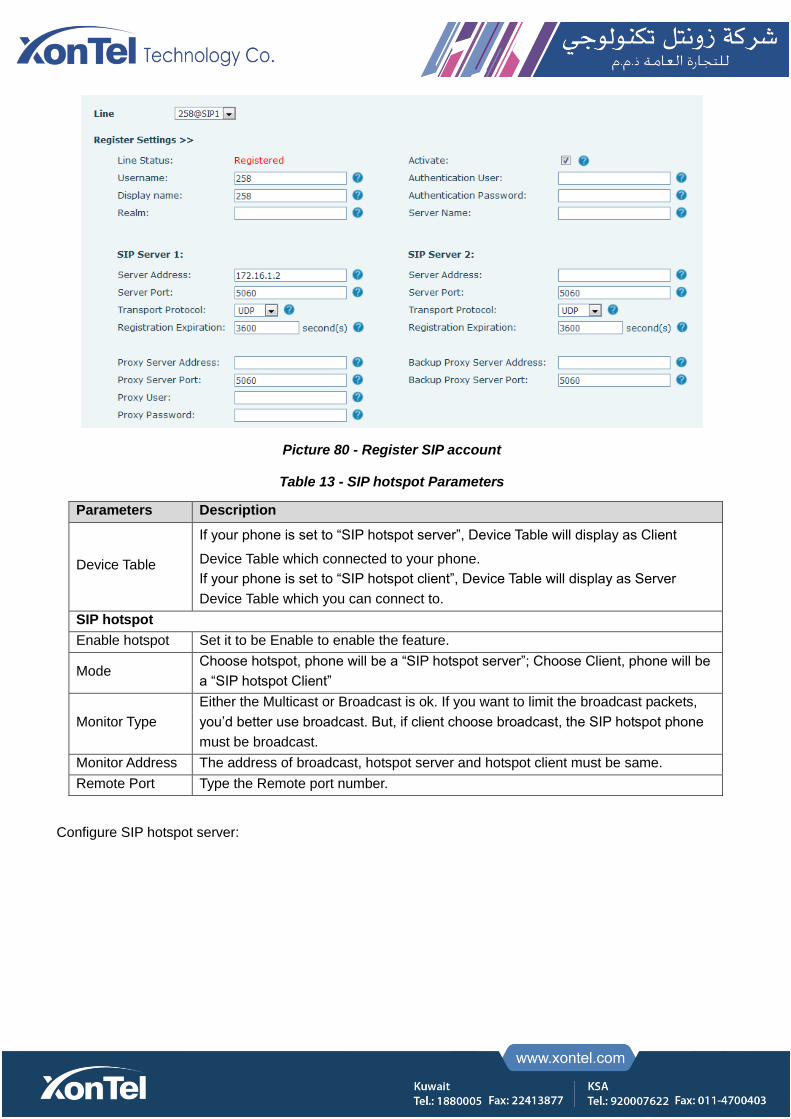
Picture 80 - Register SIP account
Table 13 - SIP hotspot Parameters
Parameters Description
Device Table
If your phone is set to “SIP hotspot server”, Device Table will display as Client
Device Table which connected to your phone.
If your phone is set to “SIP hotspot client”, Device Table will display as Server
Device Table which you can connect to.
SIP hotspot
Enable hotspot Set it to be Enable to enable the feature.
Mode Choose hotspot, phone will be a “SIP hotspot server”; Choose Client, phone will be
a “SIP hotspot Client”
Monitor Type
Either the Multicast or Broadcast is ok. If you want to limit the broadcast packets,
you’d better use broadcast. But, if client choose broadcast, the SIP hotspot phone
must be broadcast.
Monitor Address The address of broadcast, hotspot server and hotspot client must be same.
Remote Port Type the Remote port number.
Configure SIP hotspot server:
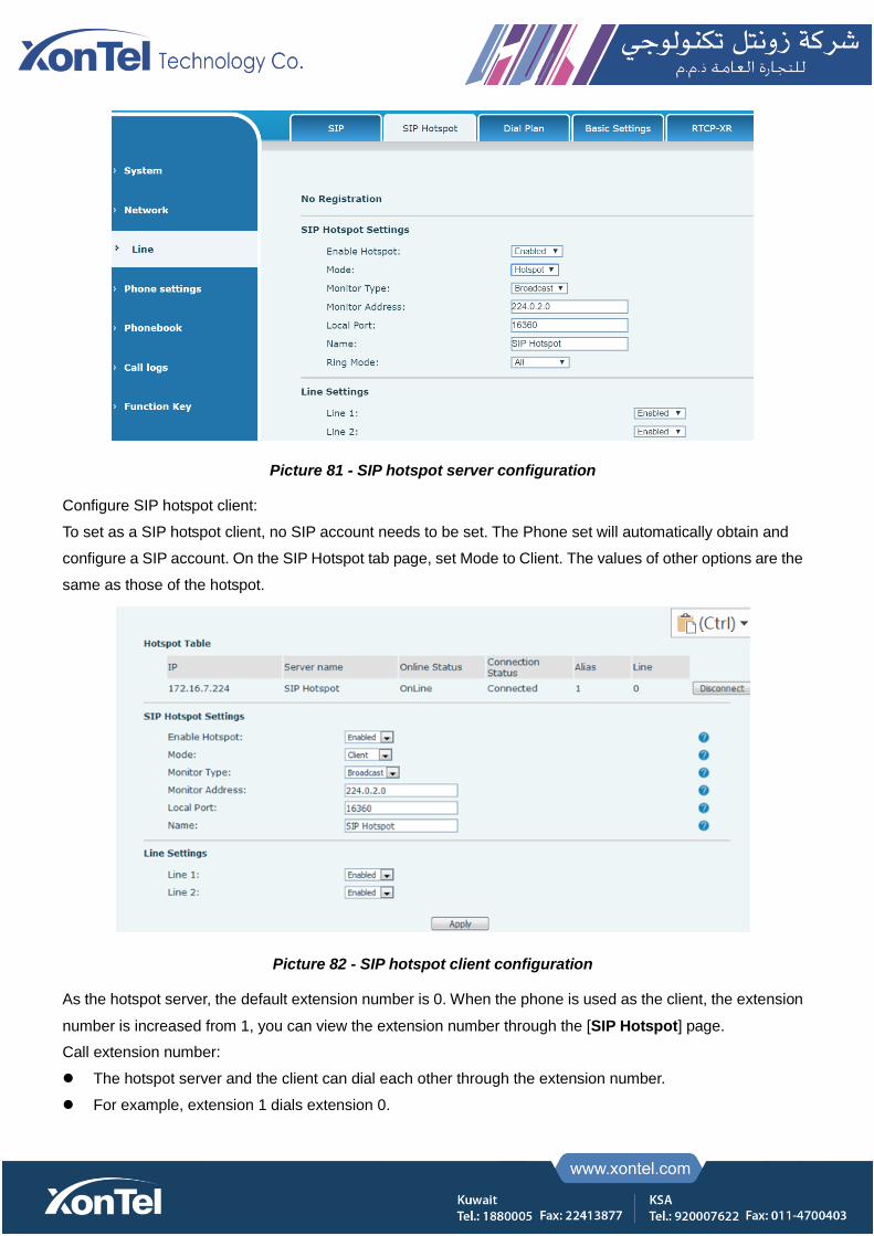
Picture 81 - SIP hotspot server configuration
Configure SIP hotspot client:
To set as a SIP hotspot client, no SIP account needs to be set. The Phone set will automatically obtain and
configure a SIP account. On the SIP Hotspot tab page, set Mode to Client. The values of other options are the
same as those of the hotspot.
Picture 82 - SIP hotspot client configuration
As the hotspot server, the default extension number is 0. When the phone is used as the client, the extension
number is increased from 1, you can view the extension number through the [SIP Hotspot] page.
Call extension number:
The hotspot server and the client can dial each other through the extension number.
For example, extension 1 dials extension 0.

8 Phone Settings
8.1 Basic Settings
8.1.1 Language
The user can set the phone language through the phone interface and web interface.
Phone end: After resetting the factory settings, the user needs to set the language; when setting the language
during standby, go to [Menu] >> [Basic] >> [Language] Settings, as shown in the figure.
Picture 83 - Phone language setting
Web interface: Log in to the phone webpage and set the language in the drop-down box at the top right
corner of the page, as shown in the figure:
Picture 84 - Language setting on Web page
The function box on the right side of the web interface language setting box is “Synchronize language to
phone”; if selected, the phone language will be synchronized with the webpage language. If it is not selected, it
will not be synchronized.
8.1.2 Time & Date
Users can set the phone time through the phone interface and web interface.
Phone end: When the phone is in the default standby state, press the [Menu] >> [Basic] >> [Time & Date],
use the up/down navigation button to edit parameters, press the [OK] to save after completion, as shown in
the figure:

Picture 85 - Set time & date on phone
Web end: Log in to the phone webpage and enter [Phone Settings] >> [Time/Date], as shown in the figure:
Picture 86 - Set time & date on webpage
Table 14 - Time Settings Parameters
Parameters Description
Mode
Auto/Manual
Auto: Enable network time synchronization via SNTP protocol, default
enabled.
Manual: User can modify data manually.
SNTP Server SNTP server address
Time zone Select the time zone
Time format
Select time format from one of the followings:
1 JAN, MON
1 January, Monday
JAN 1, MON
January 1, Monday
MON, 1 JAN
Monday, 1 January
MON, JAN 1

Monday, January 1
DD-MM-YY
DD-MM-YYYY
MM-DD-YY
MM-DD-YYYY
YY-MM-DD
YYYY-MM-DD
Separator Choose the separator between year and moth and day
12-Hour Clock Display the clock in 12-hour format
Daylight Saving Time Enable or Disable the Daylight Saving Time
8.1.3 Screen
The user can set the phone screen parameters through both of the phone interface and web interface.
Phone: When the phone is in the default standby state, go to [Menu] >> [Basic] >> [Screen Settings] to
edit the screen parameters. After editing, click [OK] to save, as shown in the figure:
Picture 87 - Set screen parameters on phone
Web: Go to [Phone Settings] >> [Advanced] Advanced, edit the screen parameters, and click Apply to
save.
8.1.3.1 Brightness and backlight
Set the brightness level in use from 1 to 16, [<] or [>] switch brightness level.
Set the brightness level in the energy-saving mode from 0 to 16, [<] or [>] switch the brightness level.
Set the backlight time to 30 seconds by default. You can turn it off or select 15 seconds /30 seconds /45
seconds /60 seconds /90 seconds /120 seconds.
The screen saver can be turned on or off by default.
Web interface: enter [Phone Settings] >> [Advanced], edit screen parameters, and click submit to save.
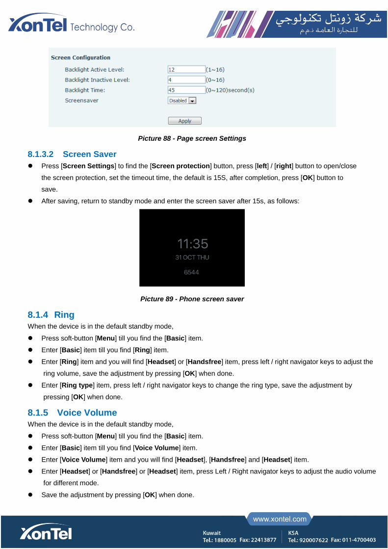
Picture 88 - Page screen Settings
8.1.3.2 Screen Saver
Press [Screen Settings] to find the [Screen protection] button, press [left] / [right] button to open/close
the screen protection, set the timeout time, the default is 15S, after completion, press [OK] button to
save.
After saving, return to standby mode and enter the screen saver after 15s, as follows:
Picture 89 - Phone screen saver
8.1.4 Ring
When the device is in the default standby mode,
Press soft-button [Menu] till you find the [Basic] item.
Enter [Basic] item till you find [Ring] item.
Enter [Ring] item and you will find [Headset] or [Handsfree] item, press left / right navigator keys to adjust the
ring volume, save the adjustment by pressing [OK] when done.
Enter [Ring type] item, press left / right navigator keys to change the ring type, save the adjustment by
pressing [OK] when done.
8.1.5 Voice Volume
When the device is in the default standby mode,
Press soft-button [Menu] till you find the [Basic] item.
Enter [Basic] item till you find [Voice Volume] item.
Enter [Voice Volume] item and you will find [Headset], [Handsfree] and [Headset] item.
Enter [Headset] or [Handsfree] or [Headset] item, press Left / Right navigator keys to adjust the audio volume
for different mode.
Save the adjustment by pressing [OK] when done.
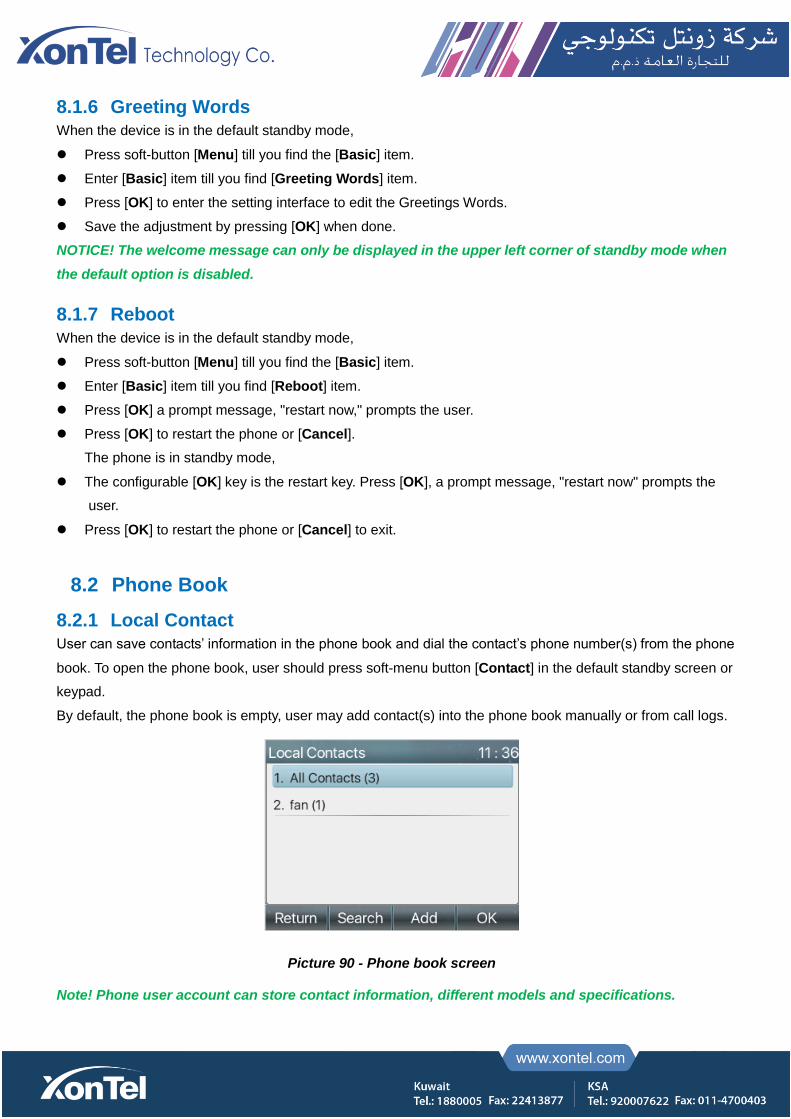
8.1.6 Greeting Words
When the device is in the default standby mode,
Press soft-button [Menu] till you find the [Basic] item.
Enter [Basic] item till you find [Greeting Words] item.
Press [OK] to enter the setting interface to edit the Greetings Words.
Save the adjustment by pressing [OK] when done.
NOTICE! The welcome message can only be displayed in the upper left corner of standby mode when
the default option is disabled.
8.1.7 Reboot
When the device is in the default standby mode,
Press soft-button [Menu] till you find the [Basic] item.
Enter [Basic] item till you find [Reboot] item.
Press [OK] a prompt message, "restart now," prompts the user.
Press [OK] to restart the phone or [Cancel].
The phone is in standby mode,
The configurable [OK] key is the restart key. Press [OK], a prompt message, "restart now" prompts the
user.
Press [OK] to restart the phone or [Cancel] to exit.
8.2 Phone Book
8.2.1 Local Contact
User can save contacts’ information in the phone book and dial the contact’s phone number(s) from the phone
book. To open the phone book, user should press soft-menu button [Contact] in the default standby screen or
keypad.
By default, the phone book is empty, user may add contact(s) into the phone book manually or from call logs.
Picture 90 - Phone book screen
Note! Phone user account can store contact information, different models and specifications.

Picture 91 - Local Phone book
When there are contact records in the phone book, the contact records will be arranged in the alphabet order.
User may browse the contacts with up/down navigator keys. The record indicator tells user which contact is
currently focused. User may check the contact’s information by pressing [OK] button.
8.2.1.1 Add / Edit / Delete Contact
To add a new contact, user should press [Add] button to open Add Contact screen and enter the contact
information of the followings,
Contact Name
Tel. Number
Mobile Number
Other Number
Line
Ring Tone
Contact Group
Photo
Picture 92 - Add New Contact
User can edit a contact by pressing [Option] >> [Edit] button.
To delete a contact, user should move the record indicator to the position of the contact to be deleted, press
[Option] >> [Delete] button and confirm with [OK].
8.2.1.2 Add / Edit / Delete Group
By default, the group list is blank. User can create his/her own groups, edit the group name, add or remove
contacts in the group, and delete a group.

To add a group, press [Add Group] button.
To delete a group, press [Option] >> [Delete] button.
To edit a group, press [Edit] button.
The Number behind the group name means the total contacts number of selected groups.
Picture 93 - Group List
8.2.1.3 Browse and Add / Remove Contacts in Group
User can browse contacts in a group by opening the group in group list with [OK] button.
Picture 94 - Browsing Contacts in a Group
When user is browsing contacts of a group, user can also add contacts in that group by pressing [Add] button to
enter the group contacts management interface, then press [OK] button to save the contact. The contact will also
be added in local phonebook. User can delete contact from group by [Option] >> [Delete].
Picture 95 - Add Contacts in a Group
8.2.2 Blacklist
The device Support blacklist, such as the number added to the blacklist, the number of calls directly refused to
the end, the end of the phone shows no incoming calls. (Blacklisted Numbers can be called out normally)

There are multiple ways to add a number to Blacklist on the device. It can be added directly on [Menu] >>
[Contact] >> [Blacklist].
Select any number in the phone book (both local and network) for configuration addition.
Select any number in the call log for configuration addition.
Picture 96 - Add Blacklist
There are various ways to add number to the blacklist on web page, which can be added in the [Phone book] >>
[Call list] >> [Restricted Incoming Calls].
Select any number in the phone book (both local and network) for configuration addition.
Select any number in the call log for configuration addition.
Picture 97 - Web Blacklist
8.2.3 Cloud Phone Book
8.2.3.1 Configure Cloud Phone book
Cloud phonebook allows user to configure the device by downloading a phonebook from a cloud server. This is
convenient for office users to use the phonebook from a single source and save the effort to create and maintain
the contact list individually. It is also a useful tool to synchronize his/her phonebook from a personal mobile phone
to the device with Cloud Phonebook Service and App which is to be provided publicly soon.
NOTICE! The cloud phonebook is ONLY temporarily downloaded to the device each time when it is
opened on the device to ensure the user get the latest phonebook. However, the downloading may take a
couple seconds depending on the network condition. Therefore, it is highly recommended for the users to
save important contacts from cloud to local phonebook for saving download time.
Open cloud phonebook list, press [Menu] >> [PhoneBook] >> [Cloud Contacts] in phonebook screen.
TIPS! The first configuration on cloud phone should be completed on Web page by selecting [PhoneBook]
>> [Cloud Contacts]. The setting of addition/deletion on device could be done after the first setting on
Web page.

Picture 98 - Cloud phone book list
8.2.3.2 Downloading Cloud Phone book
In cloud phone book screen, user can open a cloud phone book by pressing [OK] / [Enter] button. The device will
start downloading the phone book. The user will be prompted with a warning message if the download fails,
Once the cloud phone book is downloaded completely, the user can browse the contact list and dial the contact
number same as in local phonebook.
Picture 99 - Downloading Cloud Phone book
Picture 100 - Browsing Contacts in Cloud Phone book
8.3 Call Log
The phone can store the call record (the quantity of storage varies according to different specifications). The user
can press [CallLog] to open the call record and check the records of all incoming calls, outgoing calls and missed
calls.
In the call logs interface, user may browse the call logs with up/down navigator keys.
Each call log record is presented with ‘call type’ and ‘call party number / name’. User can check further call log detail

by pressing [OK] button and dial the number with [Dial] button, or add the call log number to phonebook with
pressing [Option] >> [Add to Contact].
User can delete a call log by pressing [Delete] button and clear all call logs by pressing [Delete All] button.
Picture 101 - Call Log
Users can also filter the call records of specific call types to narrow down the scope of search records, and
select a call record type by left and right navigation keys.
- Missed Call Log
- Incoming Call Log
- Outgoing Call Log
- Forward Call Log
Picture 102 - Filter call record types
8.4 Function Key
Users can use the page switch key to switch DSS display pages quickly. In addition, the user can also long
press each DSS key to modify the corresponding key Settings.
Picture 103 - DSS LCD key Page Configuration Screen
The DSS Key could be configured as followings,
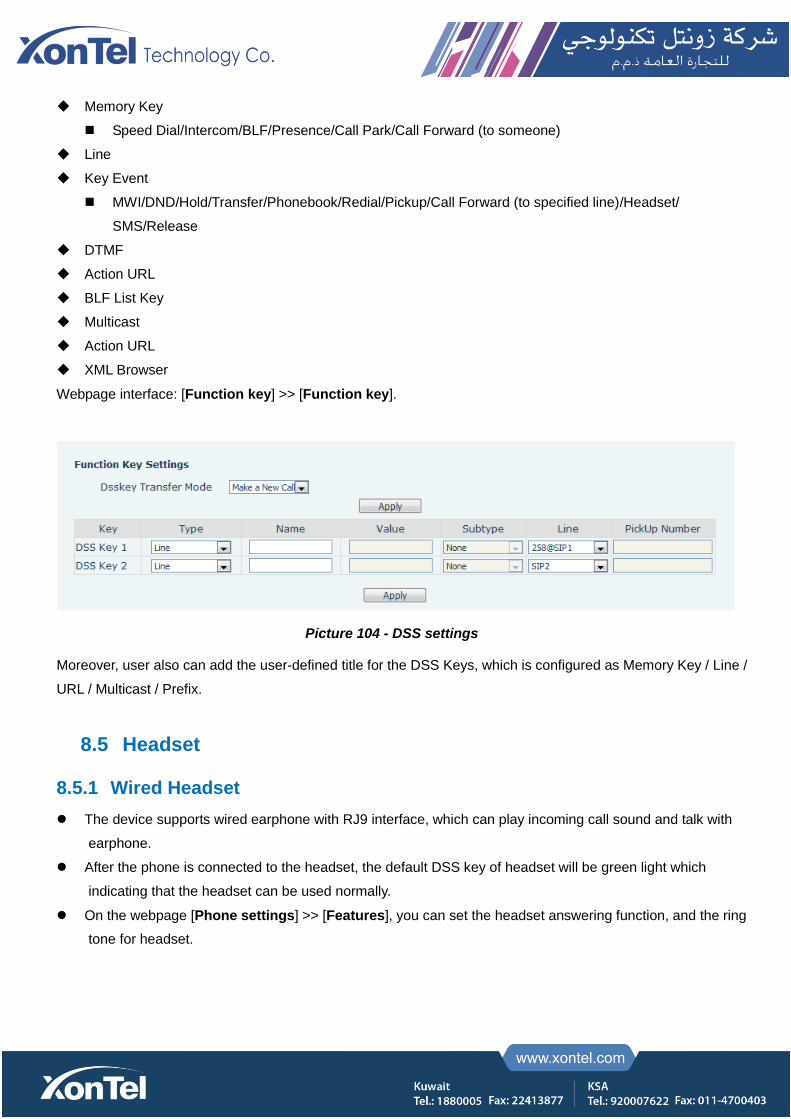
Memory Key
Speed Dial/Intercom/BLF/Presence/Call Park/Call Forward (to someone)
Line
Key Event
MWI/DND/Hold/Transfer/Phonebook/Redial/Pickup/Call Forward (to specified line)/Headset/
SMS/Release
DTMF
Action URL
BLF List Key
Multicast
Action URL
XML Browser
Webpage interface: [Function key] >> [Function key].
Picture 104 - DSS settings
Moreover, user also can add the user-defined title for the DSS Keys, which is configured as Memory Key / Line /
URL / Multicast / Prefix.
8.5 Headset
8.5.1 Wired Headset
The device supports wired earphone with RJ9 interface, which can play incoming call sound and talk with
earphone.
After the phone is connected to the headset, the default DSS key of headset will be green light which
indicating that the headset can be used normally.
On the webpage [Phone settings] >> [Features], you can set the headset answering function, and the ring
tone for headset.
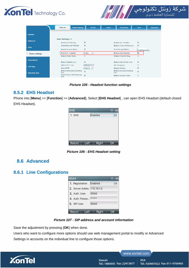
Picture 105 - Headset function settings
8.5.2 EHS Headset
Phone into [Menu] >> [Function] >> [Advanced], Select [EHS Headset] , can open EHS Headset (default closed
EHS Headset).
Picture 106 - EHS Headset setting
8.6 Advanced
8.6.1 Line Configurations
Picture 107 - SIP address and account information
Save the adjustment by pressing [OK] when done.
Users who want to configure more options should use web management portal to modify or Advanced
Settings in accounts on the individual line to configure those options.

Picture 108 - Configure Advanced Line Options
8.6.2 Network Settings
8.6.2.1 Network Settings
IP Mode
There are 3 network protocol mode options, IPv4, IPv6 and IPv4 & IPv6.
User could select available mode via “<” or “>”. The selected IP mode will be activated after pressing [OK] button.
Picture 109 - Network mode Settings
IPv4
In IPv4 mode, there are 3 connection mode options: DHCP, PPPoE and Static IP.
Picture 110 - DHCP network mode
When using DHCP mode, phone will get the IP address from DHCP server (router).
Use DHCP DNS: It is enabled as default. “Enable” means phone will get DNS address from DHCP server
and “disable” means not.
Use DHCP time: It is disabled as default. “Enable” to manage the time of get DNS address from DHCP
server and “disable” means not.

Picture 111 - PPPoE network mode
When using PPPoE, phone will get the IP address from PPPoE server.
Username: PPPoE user name.
Password: PPPoE password.
Picture 112 - Static IP network mode
When using Static IP mode, user must configure the IP address manually.
IP Address: Phone IP address.
Mask: sub mask of your LAN.
Gateway: The gateway IP address. Phone could access the other network via it.
Primary DNS: Primary DNS address. The default is 8.8.8.8, Google DNS server address.
Secondary DNS: When primary DNS is not available, Secondary DNS will work.
IPv6
In IPv6, there are 2 connection mode options, DHCP and Static IP.
DHCP configuration refers to IPv4 introduction in last page.
Static IP configuration is almost same as IPv4’s, except the IPv6 Prefix.
IPv6 Prefix: IPv6 prefix, it is similar with mask of IPv4.
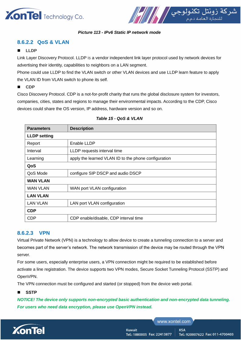
Picture 113 - IPv6 Static IP network mode
8.6.2.2 QoS & VLAN
LLDP
Link Layer Discovery Protocol. LLDP is a vendor independent link layer protocol used by network devices for
advertising their identity, capabilities to neighbors on a LAN segment.
Phone could use LLDP to find the VLAN switch or other VLAN devices and use LLDP learn feature to apply
the VLAN ID from VLAN switch to phone its self.
CDP
Cisco Discovery Protocol. CDP is a not-for-profit charity that runs the global disclosure system for investors,
companies, cities, states and regions to manage their environmental impacts. According to the CDP, Cisco
devices could share the OS version, IP address, hardware version and so on.
Table 15 - QoS & VLAN
Parameters Description
LLDP setting
Report Enable LLDP
Interval LLDP requests interval time
Learning apply the learned VLAN ID to the phone configuration
QoS
QoS Mode configure SIP DSCP and audio DSCP
WAN VLAN
WAN VLAN WAN port VLAN configuration
LAN VLAN
LAN VLAN LAN port VLAN configuration
CDP
CDP CDP enable/disable, CDP interval time
8.6.2.3 VPN
Virtual Private Network (VPN) is a technology to allow device to create a tunneling connection to a server and
becomes part of the server’s network. The network transmission of the device may be routed through the VPN
server.
For some users, especially enterprise users, a VPN connection might be required to be established before
activate a line registration. The device supports two VPN modes, Secure Socket Tunneling Protocol (SSTP) and
OpenVPN.
The VPN connection must be configured and started (or stopped) from the device web portal.
SSTP
NOTICE! The device only supports non-encrypted basic authentication and non-encrypted data tunneling.
For users who need data encryption, please use OpenVPN instead.

To establish a SSTP connection, users should log in to the device web portal, open webpage [Network] >>
[VPN]. In VPN Mode, check the “Enable VPN” option and select “SSTP”, then fill in the SSTP server address,
Authentication Username, and Authentication Password in the SSTP section. Press “Apply” then the device
will try to connect to the SSTP server.
When the VPN connection established, the VPN IP Address should be displayed in the VPN status. There
may be the delay of the connection establishment. User may need to refresh the page to update the status.
Once the VPN is configured, the device will try to connect with the VPN automatically when the device boots
up every time until user disable it. Sometimes, if the VPN connection does not establish immediately, user
may try to reboot the device and check if VPN connection established after reboot.
OpenVPN
To establish an OpenVPN connection, user should get the following authentication and configuration files
from the OpenVPN hosting provider and name them as the following,
OpenVPN Configuration file: client.ovpn
CA Root Certification: ca.crt
Client Certification: client.crt
Client Key: client.key
User then upload these files to the device in the web page [Network] >> [VPN], select OpenVPN Files. Then user
should check “Enable VPN” and select “OpenVPN” in VPN Mode and click “Apply” to enable OpenVPN
connection.
Same as SSTP connection, the connection will be established every time when system rebooted until user disable
it manually.
8.6.2.4 Web Server Type
Configure the Web Server mode to be HTTP or HTTPS and will be activated after the reboot. Then user could
use http/https protocol to access pone web page.
Picture 114 - The phone configures the web server type
8.6.3 Set The Secret Key
When the device is in the default standby mode,
Select [Menu] >> [Advanced setting], and enter it via [Confirm] or [OK] button.
As default, the Advance setting password is 123.
User will see the follow page after menu – Advanced setting – Security.

Picture 115 - Keypad lock password
Menu password is the permission for accessing the advanced setting.
[Current password] is the password user configured before. If no configuration before, the default
password is 123.
[New password] is the new password user to use.
After configuring the menu password, it will work immediately.
Keyboard password is used to unlock the phone once it’s locked.
Picture 116 - Set keyboard lock password
User could only set to enable or disable the keyboard password in LCD screen.
Enter [Keyboard password] setting by pressing [confirm] or [OK] button after password entered. If no menu
password configuration before, it is 123 as default.
If the menu password is correct, phone will go to keyboard password interface. As default, the keyboard
password is disabled. When it is enabled, the keyboard will be locked after timeout.
If user does not configure the keyboard lock time, (it is 0 as default). Long pressing “#” will lock the phone.
There will be a lock icon in the top of LCD. Phone will reminder “Enter Password” after pressing any keys.
Picture 117 - Phone keypad lock password input interface
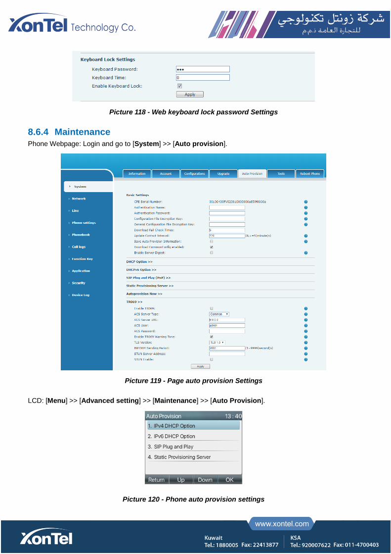
Picture 118 - Web keyboard lock password Settings
8.6.4 Maintenance
Phone Webpage: Login and go to [System] >> [Auto provision].
Picture 119 - Page auto provision Settings
LCD: [Menu] >> [Advanced setting] >> [Maintenance] >> [Auto Provision].
Picture 120 - Phone auto provision settings
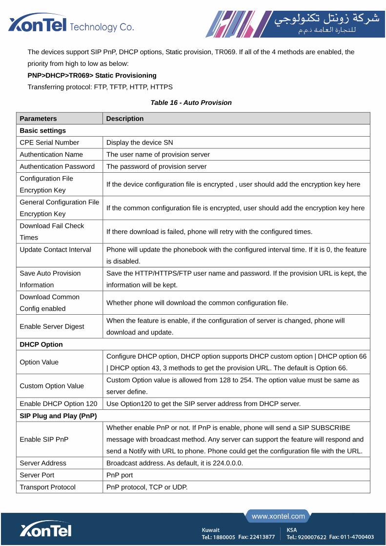
The devices support SIP PnP, DHCP options, Static provision, TR069. If all of the 4 methods are enabled, the
priority from high to low as below:
PNP>DHCP>TR069> Static Provisioning
Transferring protocol: FTP, TFTP, HTTP, HTTPS
Table 16 - Auto Provision
Parameters Description
Basic settings
CPE Serial Number Display the device SN
Authentication Name The user name of provision server
Authentication Password The password of provision server
Configuration File
Encryption Key If the device configuration file is encrypted , user should add the encryption key here
General Configuration File
Encryption Key If the common configuration file is encrypted, user should add the encryption key here
Download Fail Check
Times If there download is failed, phone will retry with the configured times.
Update Contact Interval
Phone will update the phonebook with the configured interval time. If it is 0, the feature
is disabled.
Save Auto Provision
Information
Save the HTTP/HTTPS/FTP user name and password. If the provision URL is kept, the
information will be kept.
Download Common
Config enabled Whether phone will download the common configuration file.
Enable Server Digest When the feature is enable, if the configuration of server is changed, phone will
download and update.
DHCP Option
Option Value Configure DHCP option, DHCP option supports DHCP custom option | DHCP option 66
| DHCP option 43, 3 methods to get the provision URL. The default is Option 66.
Custom Option Value Custom Option value is allowed from 128 to 254. The option value must be same as
server define.
Enable DHCP Option 120 Use Option120 to get the SIP server address from DHCP server.
SIP Plug and Play (PnP)
Enable SIP PnP
Whether enable PnP or not. If PnP is enable, phone will send a SIP SUBSCRIBE
message with broadcast method. Any server can support the feature will respond and
send a Notify with URL to phone. Phone could get the configuration file with the URL.
Server Address Broadcast address. As default, it is 224.0.0.0.
Server Port PnP port
Transport Protocol PnP protocol, TCP or UDP.
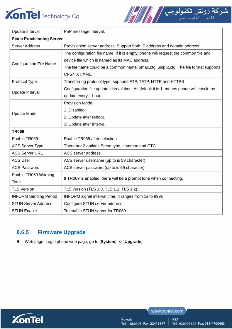
Update Interval PnP message interval.
Static Provisioning Server
Server Address Provisioning server address. Support both IP address and domain address.
Configuration File Name
The configuration file name. If it is empty, phone will request the common file and
device file which is named as its MAC address.
The file name could be a common name, $mac.cfg, $input.cfg. The file format supports
CFG/TXT/XML.
Protocol Type Transferring protocol type, supports FTP, TFTP, HTTP and HTTPS
Update Interval Configuration file update interval time. As default it is 1, means phone will check the
update every 1 hour.
Update Mode
Provision Mode.
1. Disabled.
2. Update after reboot.
3. Update after interval.
TR069
Enable TR069 Enable TR069 after selection
ACS Server Type There are 2 options Serve type, common and CTC.
ACS Server URL ACS server address
ACS User ACS server username (up to is 59 character)
ACS Password ACS server password (up to is 59 character)
Enable TR069 Warning
Tone If TR069 is enabled, there will be a prompt tone when connecting.
TLS Version TLS version (TLS 1.0, TLS 1.1, TLS 1.2)
INFORM Sending Period INFORM signal interval time. It ranges from 1s to 999s
STUN Server Address Configure STUN server address
STUN Enable To enable STUN server for TR069
8.6.5 Firmware Upgrade
Web page: Login phone web page, go to [System] >> [Upgrade].
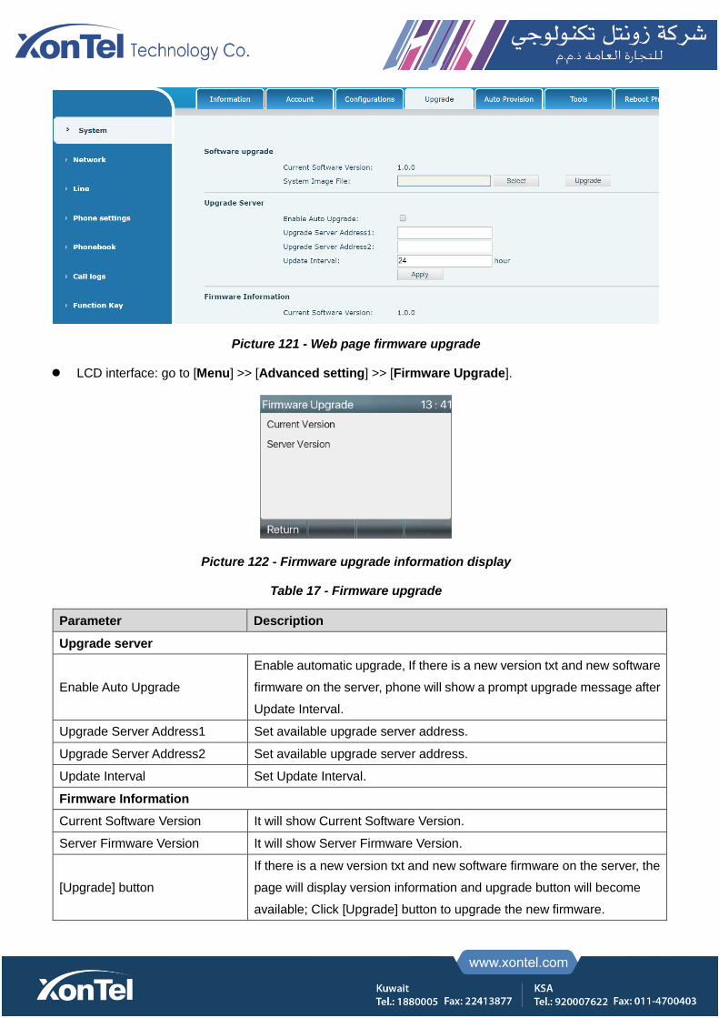
Picture 121 - Web page firmware upgrade
LCD interface: go to [Menu] >> [Advanced setting] >> [Firmware Upgrade].
Picture 122 - Firmware upgrade information display
Table 17 - Firmware upgrade
Parameter Description
Upgrade server
Enable Auto Upgrade
Enable automatic upgrade, If there is a new version txt and new software
firmware on the server, phone will show a prompt upgrade message after
Update Interval.
Upgrade Server Address1 Set available upgrade server address.
Upgrade Server Address2 Set available upgrade server address.
Update Interval Set Update Interval.
Firmware Information
Current Software Version It will show Current Software Version.
Server Firmware Version It will show Server Firmware Version.
[Upgrade] button
If there is a new version txt and new software firmware on the server, the
page will display version information and upgrade button will become
available; Click [Upgrade] button to upgrade the new firmware.
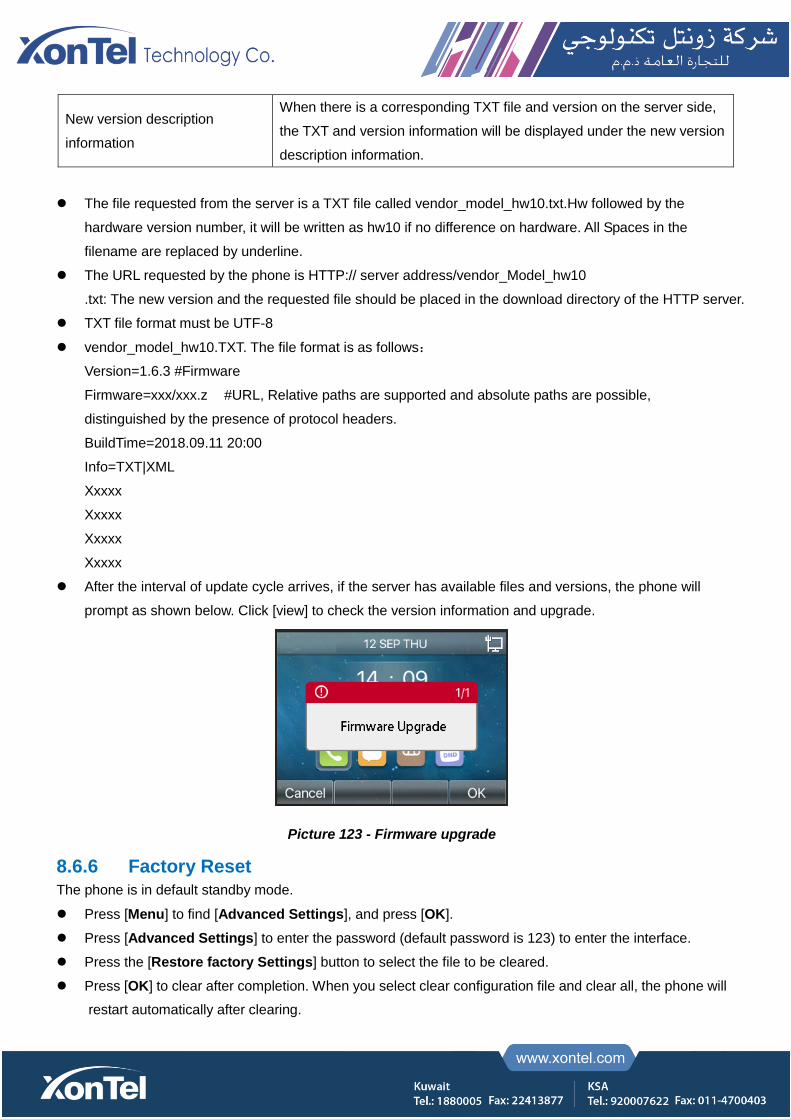
New version description
information
When there is a corresponding TXT file and version on the server side,
the TXT and version information will be displayed under the new version
description information.
The file requested from the server is a TXT file called vendor_model_hw10.txt.Hw followed by the
hardware version number, it will be written as hw10 if no difference on hardware. All Spaces in the
filename are replaced by underline.
The URL requested by the phone is HTTP:// server address/vendor_Model_hw10
.txt: The new version and the requested file should be placed in the download directory of the HTTP server.
TXT file format must be UTF-8
vendor_model_hw10.TXT. The file format is as follows:
Version=1.6.3 #Firmware
Firmware=xxx/xxx.z #URL, Relative paths are supported and absolute paths are possible,
distinguished by the presence of protocol headers.
BuildTime=2018.09.11 20:00
Info=TXT|XML
Xxxxx
Xxxxx
Xxxxx
Xxxxx
After the interval of update cycle arrives, if the server has available files and versions, the phone will
prompt as shown below. Click [view] to check the version information and upgrade.
Picture 123 - Firmware upgrade
8.6.6 Factory Reset
The phone is in default standby mode.
Press [Menu] to find [Advanced Settings], and press [OK].
Press [Advanced Settings] to enter the password (default password is 123) to enter the interface.
Press the [Restore factory Settings] button to select the file to be cleared.
Press [OK] to clear after completion. When you select clear configuration file and clear all, the phone will
restart automatically after clearing.
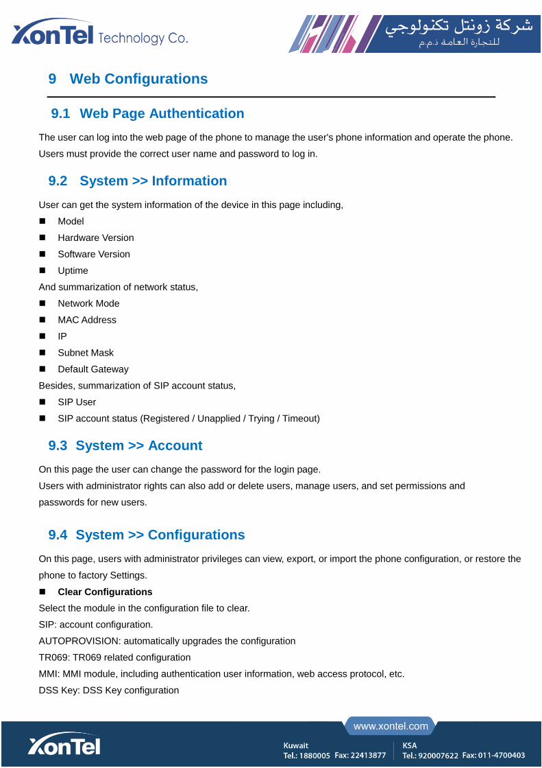
9 Web Configurations
9.1 Web Page Authentication
The user can log into the web page of the phone to manage the user's phone information and operate the phone.
Users must provide the correct user name and password to log in.
9.2 System >> Information
User can get the system information of the device in this page including,
Model
Hardware Version
Software Version
Uptime
And summarization of network status,
Network Mode
MAC Address
IP
Subnet Mask
Default Gateway
Besides, summarization of SIP account status,
SIP User
SIP account status (Registered / Unapplied / Trying / Timeout)
9.3 System >> Account
On this page the user can change the password for the login page.
Users with administrator rights can also add or delete users, manage users, and set permissions and
passwords for new users.
9.4 System >> Configurations
On this page, users with administrator privileges can view, export, or import the phone configuration, or restore the
phone to factory Settings.
Clear Configurations
Select the module in the configuration file to clear.
SIP: account configuration.
AUTOPROVISION: automatically upgrades the configuration
TR069: TR069 related configuration
MMI: MMI module, including authentication user information, web access protocol, etc.
DSS Key: DSS Key configuration
Clear Data Tables
Select the local data table to be cleared, all selected by default.
Reset Phone
The phone data will be cleared, including configuration and database tables.
9.5 System >> Upgrade
Upgrade the phone software version, customized ringtone, background, DSS Key icon, etc., can also be
upgraded to delete the file. Ring tone support “.wav” format.
9.6 System >> Auto Provision
The Auto Provision settings help IT manager or service provider to easily deploy and manage the devices in
mass volume. For the detail of Auto Provision, please refer to this link Auto Provision Description。
9.7 System >> Tools
Tools provided in this page help users to identify issues at trouble shooting.
9.8 System >> Reboot Phone
This page can restart the phone.

10 Network >> Basic
This page allows users to configure network connection types and parameters.
10.1 Network >> Service Port
This page provides settings for Web page login protocol, protocol port settings and RTP port.
Picture 124 - Service Port Settings
Table 18 - Service port
Parameter Description
Web Server Type Reboot to take effect after settings. Optionally, the web page login is
HTTP/HTTPS.
Web Logon Timeout Default as 15 minutes, the timeout will automatically exit the login page, need
to login again.
Web auto login After the timeout does not need to enter a user name password, will
automatically login to the web page.
HTTP Port The default is 80. If you want system security, you can set ports other than 80.
Such as :8080, webpage login: HTTP://ip:8080
HTTPS Port The default is 443, the same as the HTTP port.
RTP Port Range Start The value range is 1025 to 65535. The value of RTP port starts from the initial
value set. For each call, the value of voice and video port is added 2.
RTP Port Quantity Number of calls.
10.2 Network >> VPN
Users can configure a VPN connection on this page.
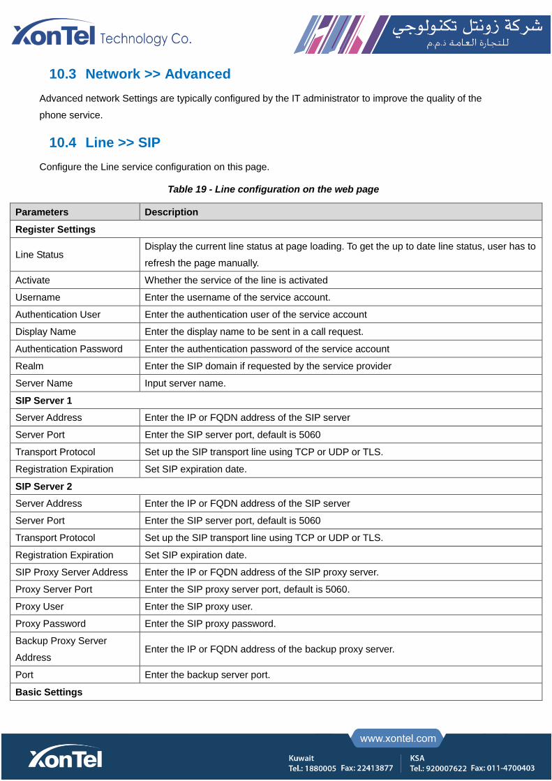
10.3 Network >> Advanced
Advanced network Settings are typically configured by the IT administrator to improve the quality of the
phone service.
10.4 Line >> SIP
Configure the Line service configuration on this page.
Table 19 - Line configuration on the web page
Parameters Description
Register Settings
Line Status Display the current line status at page loading. To get the up to date line status, user has to
refresh the page manually.
Activate Whether the service of the line is activated
Username Enter the username of the service account.
Authentication User Enter the authentication user of the service account
Display Name Enter the display name to be sent in a call request.
Authentication Password Enter the authentication password of the service account
Realm Enter the SIP domain if requested by the service provider
Server Name Input server name.
SIP Server 1
Server Address Enter the IP or FQDN address of the SIP server
Server Port Enter the SIP server port, default is 5060
Transport Protocol Set up the SIP transport line using TCP or UDP or TLS.
Registration Expiration Set SIP expiration date.
SIP Server 2
Server Address Enter the IP or FQDN address of the SIP server
Server Port Enter the SIP server port, default is 5060
Transport Protocol Set up the SIP transport line using TCP or UDP or TLS.
Registration Expiration Set SIP expiration date.
SIP Proxy Server Address Enter the IP or FQDN address of the SIP proxy server.
Proxy Server Port Enter the SIP proxy server port, default is 5060.
Proxy User Enter the SIP proxy user.
Proxy Password Enter the SIP proxy password.
Backup Proxy Server
Address Enter the IP or FQDN address of the backup proxy server.
Port Enter the backup server port.
Basic Settings

Enable Auto Answering Enable auto-answering, the incoming calls will be answered automatically after the delay
time
Auto Answering Delay Set the delay for incoming call before the system automatically answered it
Call Forward Unconditional Enable unconditional call forward, all incoming calls will be forwarded to the number
specified in the next field
Call Forward Number for
Unconditional Set the number of unconditional call forward
Call Forward on Busy Enable call forward on busy, when the phone is busy, any incoming call will be forwarded to
the number specified in the next field.
Call Forward Number for
Busy Set the number of call forward on busy .
Call Forward on No Answer Enable call forward on no answer, when an incoming call is not answered within the
configured delay time, the call will be forwarded to the number specified in the next field.
Call Forward Number for
No Answer Set the number of call forward on no answer.
Call Forward Delay for No
Answer Set the delay time of not answered call before being forwarded.
Transfer Timeout Set the timeout of call transfer process.
Conference Type
Set the type of call conference, Local=set up call conference by the device itself, maximum
supports two remote parties, Server=set up call conference by dialing to a conference room
on the server
Server Conference Number Set the conference room number when conference type is set to be Server
Subscribe For Voice
Message
Enable the device to subscribe a voice message waiting notification, if enabled, the device
will receive notification from the server if there is voice message waiting on the server
Voice Message Number Set the number for retrieving voice message
Voice Message Subscribe
Period Set the interval of voice message notification subscription
Enable Hotline Enabling hotline configuration, the device will dial to the specific number immediately at
audio channel opened by off-hook handset or turn on hands-free speaker or headphone
Hotline Delay Set the delay for hotline before the system automatically dialed it
Hotline Number Set the hotline dialing number
Dial Without Registered Set call out by proxy without registration
Enable Missed Call Log If enabled, the phone will save missed calls into the call history record.
DTMF Type Set the DTMF type to be used for the line
DTMF SIP INFO Mode Set the SIP INFO mode to send ‘*’ and ‘#’ or ‘10’ and ‘11’
Enable DND Enable Do-not-disturb, any incoming call to this line will be rejected automatically
Subscribe For Voice
Message
Enable the device to subscribe a voice message waiting notification, if enabled, the device
will receive notification from the server if there is voice message waiting on the server

Use VPN Set the line to use VPN restrict route
Use STUN Set the line to use STUN for NAT traversal
Enable Failback Whether to switch to the primary server when it is available.
Failback Interval A Register message is used to periodically detect the time interval for the availability of the
main Proxy.
Signal Failback Multiple proxy cases, whether to allow the invite/register request to also execute failback.
Signal Retry Counts The number of attempts that the SIP Request considers proxy unavailable under multiple
proxy scenarios.
Codecs Settings Set the priority and availability of the codecs by adding or remove them from the list.
Video Codecs Select video code to preview video.
Advanced Settings
Use Feature Code
When this setting is enabled, the features in this section will not be handled by the device
itself but by the server instead. In order to control the enabling of the features, the device
will send feature code to the server by dialing the number specified in each feature code
field.
Enable DND Set the feature code to dial to the server
Disable DND Set the feature code to dial to the server
Enable Call Forward
Unconditional Set the feature code to dial to the server
Disable Call Forward
Unconditional Set the feature code to dial to the server
Enable Call Forward on
Busy Set the feature code to dial to the server
Disable Call Forward on
Busy Set the feature code to dial to the server
Enable Call Forward on No
Answer Set the feature code to dial to the server
Disable Call Forward on No
Answer Set the feature code to dial to the server
Enable Blocking
Anonymous Call Set the feature code to dial to the server
Disable Blocking
Anonymous Call Set the feature code to dial to the server
Call Waiting On Code Set the feature code to dial to the server
Call Waiting Off Code Set the feature code to dial to the server
Send Anonymous On Code Set the feature code to dial to the server
Send Anonymous Off Code Set the feature code to dial to the server
SIP Encryption Enable SIP encryption such that SIP transmission will be encrypted
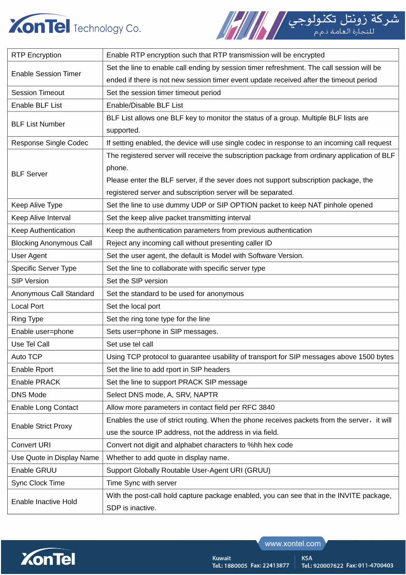
RTP Encryption Enable RTP encryption such that RTP transmission will be encrypted
Enable Session Timer Set the line to enable call ending by session timer refreshment. The call session will be
ended if there is not new session timer event update received after the timeout period
Session Timeout Set the session timer timeout period
Enable BLF List Enable/Disable BLF List
BLF List Number BLF List allows one BLF key to monitor the status of a group. Multiple BLF lists are
supported.
Response Single Codec If setting enabled, the device will use single codec in response to an incoming call request
BLF Server
The registered server will receive the subscription package from ordinary application of BLF
phone.
Please enter the BLF server, if the sever does not support subscription package, the
registered server and subscription server will be separated.
Keep Alive Type Set the line to use dummy UDP or SIP OPTION packet to keep NAT pinhole opened
Keep Alive Interval Set the keep alive packet transmitting interval
Keep Authentication Keep the authentication parameters from previous authentication
Blocking Anonymous Call Reject any incoming call without presenting caller ID
User Agent Set the user agent, the default is Model with Software Version.
Specific Server Type Set the line to collaborate with specific server type
SIP Version Set the SIP version
Anonymous Call Standard Set the standard to be used for anonymous
Local Port Set the local port
Ring Type Set the ring tone type for the line
Enable user=phone Sets user=phone in SIP messages.
Use Tel Call Set use tel call
Auto TCP Using TCP protocol to guarantee usability of transport for SIP messages above 1500 bytes
Enable Rport Set the line to add rport in SIP headers
Enable PRACK Set the line to support PRACK SIP message
DNS Mode Select DNS mode, A, SRV, NAPTR
Enable Long Contact Allow more parameters in contact field per RFC 3840
Enable Strict Proxy Enables the use of strict routing. When the phone receives packets from the server,it will
use the source IP address, not the address in via field.
Convert URI Convert not digit and alphabet characters to %hh hex code
Use Quote in Display Name Whether to add quote in display name.
Enable GRUU Support Globally Routable User-Agent URI (GRUU)
Sync Clock Time Time Sync with server
Enable Inactive Hold With the post-call hold capture package enabled, you can see that in the INVITE package,
SDP is inactive.
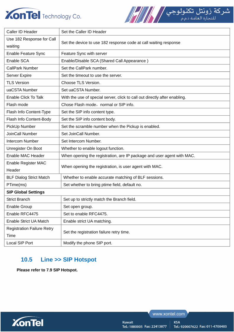
Caller ID Header Set the Caller ID Header
Use 182 Response for Call
waiting Set the device to use 182 response code at call waiting response
Enable Feature Sync Feature Sync with server
Enable SCA Enable/Disable SCA (Shared Call Appearance )
CallPark Number Set the CallPark number.
Server Expire Set the timeout to use the server.
TLS Version Choose TLS Version.
uaCSTA Number Set uaCSTA Number.
Enable Click To Talk With the use of special server, click to call out directly after enabling.
Flash mode Chose Flash mode,normal or SIP info.
Flash Info Content-Type Set the SIP info content type.
Flash Info Content-Body Set the SIP info content body.
PickUp Number Set the scramble number when the Pickup is enabled.
JoinCall Number Set JoinCall Number.
Intercom Number Set Intercom Number.
Unregister On Boot Whether to enable logout function.
Enable MAC Header When opening the registration, are IP package and user agent with MAC.
Enable Register MAC
Header When opening the registration, is user agent with MAC.
BLF Dialog Strict Match Whether to enable accurate matching of BLF sessions.
PTime(ms) Set whether to bring ptime field, default no.
SIP Global Settings
Strict Branch Set up to strictly match the Branch field.
Enable Group Set open group.
Enable RFC4475 Set to enable RFC4475.
Enable Strict UA Match Enable strict UA matching.
Registration Failure Retry
Time Set the registration failure retry time.
Local SIP Port Modify the phone SIP port.
10.5 Line >> SIP Hotspot
Please refer to 7.9 SIP Hotspot.

10.6 Line >> Dial Plan
Picture 125 - Dial plan settings
Table 20 - Phone 7 dialing methods
Parameters Description
Press # to invoke dialing The user dials the other party's number and then adds the # number to
dial out;
Dial Fixed Length The number entered by the user is automatically dialed out when it
reaches a fixed length
Timeout dial The system dials automatically after timeout
Press # to Do Blind Transfer The user enters the number to be transferred and then presses the "#"
key to transfer the current call to a third party
Blind Transfer on Onhook After the user enters the number, hang up the handle or turn off the
hands-free function to transfer the current call to a third party.
Attended Transfer on Onhook
Hang up the handle or press the hands-free button to realize the function
of attention
-transfer, which can transfer the current call to a third party.
Attended Transfer on
Conference Onhook
During a three-way call, hang up the handle and the remaining two parties
remain on the call.
Enable E.164 Please refer to e. 164 standard specification
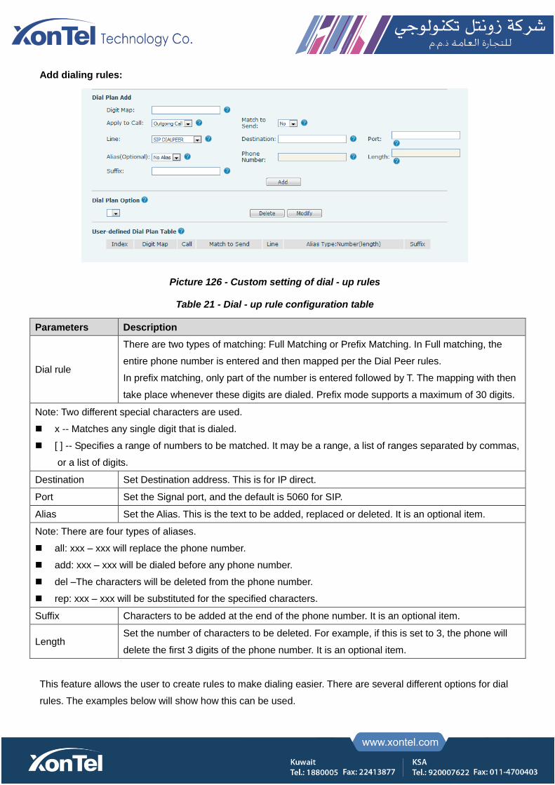
Add dialing rules:
Picture 126 - Custom setting of dial - up rules
Table 21 - Dial - up rule configuration table
Parameters Description
Dial rule
There are two types of matching: Full Matching or Prefix Matching. In Full matching, the
entire phone number is entered and then mapped per the Dial Peer rules.
In prefix matching, only part of the number is entered followed by T. The mapping with then
take place whenever these digits are dialed. Prefix mode supports a maximum of 30 digits.
Note: Two different special characters are used.
x -- Matches any single digit that is dialed.
[ ] -- Specifies a range of numbers to be matched. It may be a range, a list of ranges separated by commas,
or a list of digits.
Destination Set Destination address. This is for IP direct.
Port Set the Signal port, and the default is 5060 for SIP.
Alias Set the Alias. This is the text to be added, replaced or deleted. It is an optional item.
Note: There are four types of aliases.
all: xxx – xxx will replace the phone number.
add: xxx – xxx will be dialed before any phone number.
del –The characters will be deleted from the phone number.
rep: xxx – xxx will be substituted for the specified characters.
Suffix Characters to be added at the end of the phone number. It is an optional item.
Length Set the number of characters to be deleted. For example, if this is set to 3, the phone will
delete the first 3 digits of the phone number. It is an optional item.
This feature allows the user to create rules to make dialing easier. There are several different options for dial
rules. The examples below will show how this can be used.

Example 1: All Substitution -- Assume that it can make a direct IP call to IP address 172.168.2.208. Using
this feature, 123 can be substituted for 172.168.2.208.
Picture 127 - Dial rules table (1)
Example 2: Partial Substitution -- To dial a long distance call to Beijing requires dialing area code 010 before
the local phone number. Using this feature 1 can be substituted for 010. For example, to call 62213123 would
only require dialing 162213123 instead of 01062213123.
Picture 128 - Dial rules table (2)
Example 3: Addition -- Two examples are shown. In the first case, it is assumed that 0 must be dialed before
any 11-digit number beginning with 13. In the second case, it is assumed that 0 must be dialed before any
11-digit number beginning with 135, 136, 137, 138, or 139. Two different special characters are used.
x -- Matches any single digit that is dialed.
[] -- Specifies a range of numbers to be matched. It may be a range, a list of ranges separated by commas, or
a list of digits.
10.7 Line >> Basic Settings
Set up the register global configuration.
Table 22 - Set the line global configuration on the web page
Parameters Description
STUN Settings
Server Address Set the STUN server address
Server Port Set the STUN server port, default is 3478
Binding Period Set the STUN binding period which can be used to keep the NAT pinhole opened.
SIP Waiting Time Set the timeout of STUN binding before sending SIP messages
The TLS authentication
TLS Certification File Upload or delete the TLS certification file used for encrypted SIP transmission.

10.8 Phone settings >> Features
Configuration phone features.
Table 23 - General function Settings
Parameters Description
Basic Settings
Enable Call Waiting Enable this setting to allow user to take second incoming call during an established
call. Default enabled.
Enable Call Transfer Enable Call Transfer.
Semi-Attended Transfer Enable Semi-Attended Transfer by selecting it
Enable 3-Way Conference Enable 3-way conference by selecting it
Enable Auto Onhook The phone will hang up and return to the idle automatically at hands-free mode
Auto Onhook Time
Specify Auto Onhook time, the phone will hang up and return to the idle automatically
after Auto Hand down time at hands-free mode, and play dial tone Auto Onhook time
at handset mode
Ring for Headset Enable Ring for Handset by selecting it, the phone plays ring tone from handset.
Auto Headset Enable this feature, headset plugged in the phone, user press ‘answer’ key or line
key to answer a call with the headset automatically.
Enable Silent Mode When enabled, the phone is muted, there is no ringing when calls, you can use the
volume keys and mute key to unmute.
Disable Mute for Ring When it is enabled, you can’t mute the phone
Enable Default Line If enabled, user can assign default SIP line for dialing out rather than SIP1.
Enable Auto Switch Line Enable phone to select an available SIP line as default automatically
Default Ext Line Select the default line to use for outgoing calls
Ban Outgoing If you select Ban Outgoing to enable it, and you cannot dial out any number.
Hide DTMF Configure the hide DTMF mode.
Enable CallLog Select whether to save the call log.
Enable Restricted Incoming
List Whether to enable restricted call list.
Enable Allowed Incoming
List Whether to enable the allowed call list.
Enable Restricted Outgoing
List Whether to enable the restricted allocation list.
Enable Country Code Whether the country code is enabled.
Country Code Fill in the country code.
Area Code Fill in the area code.
Enable Number Privacy Whether to enable number privacy.

Match Direction Matching direction, there are two kinds of rules from right to left and from left to right.
Start Position Open number privacy after the start of the hidden location.
Hide Digits Turn on number privacy to hide the number of digits.
Allow IP Call If enabled, user can dial out with IP address
P2P IP Prefix Prefix a point-to-point IP call.
Caller Name Priority Change caller ID display priority.
Emergency Call Number Set Emergency Call Number
Search path Select the search path.
LDAP Search Select from with one LDAP for search
Emergency Call Number Configure the Emergency Call Number. Despite the keyboard is locked, you can dial
the emergency call number
Restrict Active URI Source
IP Set the device to accept Active URI command from specific IP address.
Push XML Server
Configure the Push XML Server, when phone receives request, it will determine
whether to display corresponding content on the phone which sent by the specified
server or not.
Enable Pre-Dial Disable this feature, user enter number will open audio channel automatically.
Enable the feature, user enter the number without opening audio channel.
Enable Multi Line If enabled, up to 10 simultaneous calls can exist on the phone, and if disabled, up to
2 simultaneous calls can exist on the phone.
Line Display Format Custom line format: SIPn/SIPn: xxx/xxx@SIPn
Contact As White List Type NONE/BOTH/DND White List/FWD White List
Block XML When Call Disable XML push on call.
SIP notify When enabled, the phone displays the information when it receives the relevant
notify content.
Tone Settings
Enable Holding Tone When turned on, a tone plays when the call is held
Enable Call Waiting Tone When turned on, a tone plays when call waiting
Play Dialing DTMF Tone Play DTMF tone on the device when user pressed a phone digits at dialing, default
enabled.
Play Talking DTMF Tone Play DTMF tone on the device when user pressed a phone digits during taking,
default enabled.
DND Settings
DND Option Select to take effect on the line or on the phone or close.
Enable DND Timer Enable DND Timer, If enabled, the DND is automatically turned on from the start time
to the off time.
DND Start Time Set DND Start Time
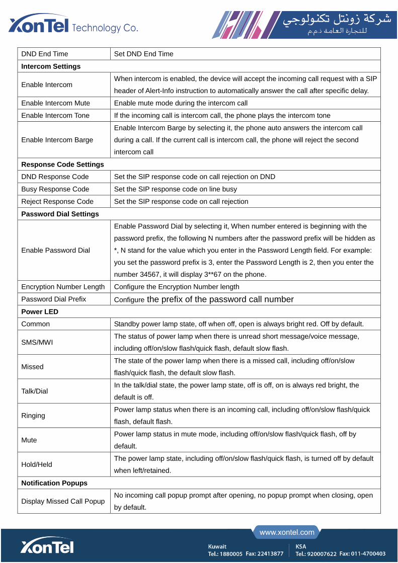
DND End Time Set DND End Time
Intercom Settings
Enable Intercom When intercom is enabled, the device will accept the incoming call request with a SIP
header of Alert-Info instruction to automatically answer the call after specific delay.
Enable Intercom Mute Enable mute mode during the intercom call
Enable Intercom Tone If the incoming call is intercom call, the phone plays the intercom tone
Enable Intercom Barge
Enable Intercom Barge by selecting it, the phone auto answers the intercom call
during a call. If the current call is intercom call, the phone will reject the second
intercom call
Response Code Settings
DND Response Code Set the SIP response code on call rejection on DND
Busy Response Code Set the SIP response code on line busy
Reject Response Code Set the SIP response code on call rejection
Password Dial Settings
Enable Password Dial
Enable Password Dial by selecting it, When number entered is beginning with the
password prefix, the following N numbers after the password prefix will be hidden as
*, N stand for the value which you enter in the Password Length field. For example:
you set the password prefix is 3, enter the Password Length is 2, then you enter the
number 34567, it will display 3**67 on the phone.
Encryption Number Length Configure the Encryption Number length
Password Dial Prefix Configure the prefix of the password call number
Power LED
Common Standby power lamp state, off when off, open is always bright red. Off by default.
SMS/MWI The status of power lamp when there is unread short message/voice message,
including off/on/slow flash/quick flash, default slow flash.
Missed The state of the power lamp when there is a missed call, including off/on/slow
flash/quick flash, the default slow flash.
Talk/Dial In the talk/dial state, the power lamp state, off is off, on is always red bright, the
default is off.
Ringing Power lamp status when there is an incoming call, including off/on/slow flash/quick
flash, default flash.
Mute Power lamp status in mute mode, including off/on/slow flash/quick flash, off by
default.
Hold/Held The power lamp state, including off/on/slow flash/quick flash, is turned off by default
when left/retained.
Notification Popups
Display Missed Call Popup No incoming call popup prompt after opening, no popup prompt when closing, open
by default.
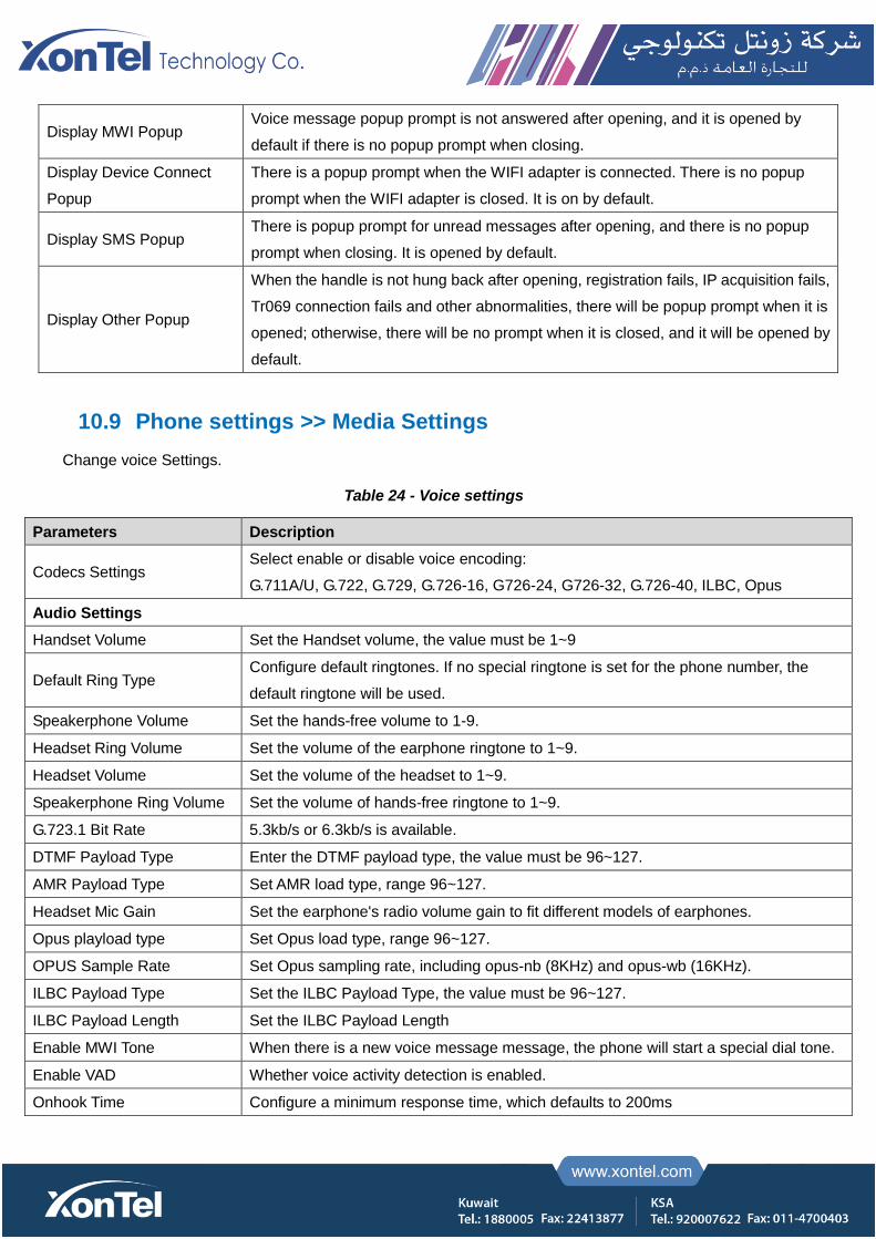
Display MWI Popup Voice message popup prompt is not answered after opening, and it is opened by
default if there is no popup prompt when closing.
Display Device Connect
Popup
There is a popup prompt when the WIFI adapter is connected. There is no popup
prompt when the WIFI adapter is closed. It is on by default.
Display SMS Popup There is popup prompt for unread messages after opening, and there is no popup
prompt when closing. It is opened by default.
Display Other Popup
When the handle is not hung back after opening, registration fails, IP acquisition fails,
Tr069 connection fails and other abnormalities, there will be popup prompt when it is
opened; otherwise, there will be no prompt when it is closed, and it will be opened by
default.
10.9 Phone settings >> Media Settings
Change voice Settings.
Table 24 - Voice settings
Parameters Description
Codecs Settings Select enable or disable voice encoding:
G.711A/U, G.722, G.729, G.726-16, G726-24, G726-32, G.726-40, ILBC, Opus
Audio Settings
Handset Volume Set the Handset volume, the value must be 1~9
Default Ring Type Configure default ringtones. If no special ringtone is set for the phone number, the
default ringtone will be used.
Speakerphone Volume Set the hands-free volume to 1-9.
Headset Ring Volume Set the volume of the earphone ringtone to 1~9.
Headset Volume Set the volume of the headset to 1~9.
Speakerphone Ring Volume Set the volume of hands-free ringtone to 1~9.
G.723.1 Bit Rate 5.3kb/s or 6.3kb/s is available.
DTMF Payload Type Enter the DTMF payload type, the value must be 96~127.
AMR Payload Type Set AMR load type, range 96~127.
Headset Mic Gain Set the earphone's radio volume gain to fit different models of earphones.
Opus playload type Set Opus load type, range 96~127.
OPUS Sample Rate Set Opus sampling rate, including opus-nb (8KHz) and opus-wb (16KHz).
ILBC Payload Type Set the ILBC Payload Type, the value must be 96~127.
ILBC Payload Length Set the ILBC Payload Length
Enable MWI Tone When there is a new voice message message, the phone will start a special dial tone.
Enable VAD Whether voice activity detection is enabled.
Onhook Time Configure a minimum response time, which defaults to 200ms
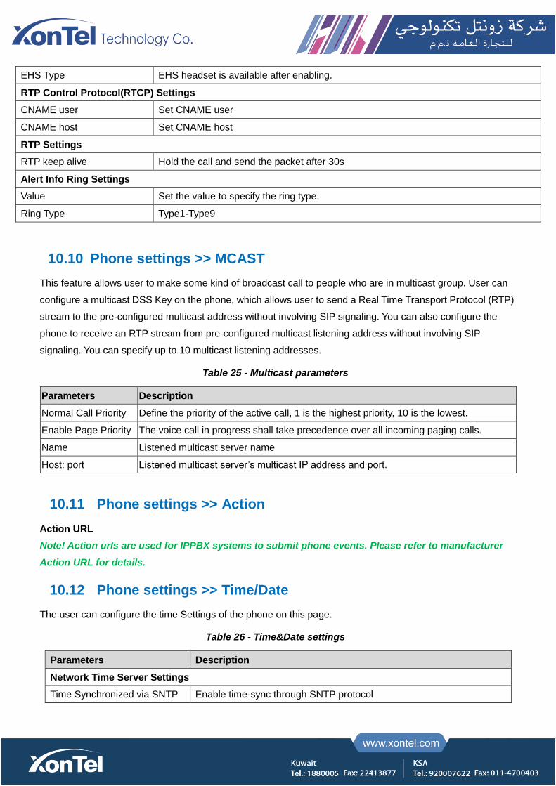
EHS Type EHS headset is available after enabling.
RTP Control Protocol(RTCP) Settings
CNAME user Set CNAME user
CNAME host Set CNAME host
RTP Settings
RTP keep alive Hold the call and send the packet after 30s
Alert Info Ring Settings
Value Set the value to specify the ring type.
Ring Type Type1-Type9
10.10 Phone settings >> MCAST
This feature allows user to make some kind of broadcast call to people who are in multicast group. User can
configure a multicast DSS Key on the phone, which allows user to send a Real Time Transport Protocol (RTP)
stream to the pre-configured multicast address without involving SIP signaling. You can also configure the
phone to receive an RTP stream from pre-configured multicast listening address without involving SIP
signaling. You can specify up to 10 multicast listening addresses.
Table 25 - Multicast parameters
Parameters Description
Normal Call Priority Define the priority of the active call, 1 is the highest priority, 10 is the lowest.
Enable Page Priority The voice call in progress shall take precedence over all incoming paging calls.
Name Listened multicast server name
Host: port Listened multicast server’s multicast IP address and port.
10.11 Phone settings >> Action
Action URL
Note! Action urls are used for IPPBX systems to submit phone events. Please refer to manufacturer
Action URL for details.
10.12 Phone settings >> Time/Date
The user can configure the time Settings of the phone on this page.
Table 26 - Time&Date settings
Parameters Description
Network Time Server Settings
Time Synchronized via SNTP Enable time-sync through SNTP protocol
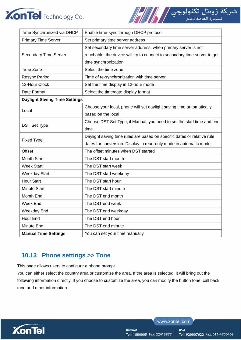
Time Synchronized via DHCP Enable time-sync through DHCP protocol
Primary Time Server Set primary time server address
Secondary Time Server
Set secondary time server address, when primary server is not
reachable, the device will try to connect to secondary time server to get
time synchronization.
Time Zone Select the time zone
Resync Period Time of re-synchronization with time server
12-Hour Clock Set the time display in 12-hour mode
Date Format Select the time/date display format
Daylight Saving Time Settings
Local Choose your local, phone will set daylight saving time automatically
based on the local
DST Set Type Choose DST Set Type, if Manual, you need to set the start time and end
time.
Fixed Type Daylight saving time rules are based on specific dates or relative rule
dates for conversion. Display in read-only mode in automatic mode.
Offset The offset minutes when DST started
Month Start The DST start month
Week Start The DST start week
Weekday Start The DST start weekday
Hour Start The DST start hour
Minute Start The DST start minute
Month End The DST end month
Week End The DST end week
Weekday End The DST end weekday
Hour End The DST end hour
Minute End The DST end minute
Manual Time Settings You can set your time manually
10.13 Phone settings >> Tone
This page allows users to configure a phone prompt.
You can either select the country area or customize the area. If the area is selected, it will bring out the
following information directly. If you choose to customize the area, you can modify the button tone, call back
tone and other information.

Picture 129 - Tone settings on the web
10.14 Phone settings >> Advanced
User can configure the advanced configuration settings in this page.
Screen Configuration.
Enable Energy Saving
Backlight Time
LCD Menu Password Settings.
The password is 123 by default.
Keyboard Lock Settings.
Configure Greeting Words
The greeting message will display on the top left corner of the LCD when the device is idle, which is limited to
16 characters. The default chars are ‘VOIP PHONE’.
10.15 Phonebook >> Contact
User can add, delete, or edit contacts in the phonebook in this page. User can browse the phonebook and sorting it
by name, phones, or filter them out by group.
To add a new contact, user should enter contact’s information and press “Add” button to add it.
To edit a contact, click on the checkbox in front of the contact, the contact information will be copied to the contact
edit boxes, press “Modify” button after finished editing.
To delete one or multiple contacts, check on the checkbox in front of the contacts wished to be deleted and click the
“Delete” button, or click the “Clear” button with selecting any contacts to clear the phonebook.
User can also add multiple contacts into a group by selecting the group in the dropdown options in front of “Add to
Group” button at the bottom of the contact list, selecting contacts with checkbox and click “Add to Group” to add
selected contacts into the group.
Similarly, user can select multiple users and add them into blacklist by click “Add to Blacklist” button.
10.16 Phonebook >> Cloud phonebook
Cloud Phonebook
User can configure up to 8 cloud phonebooks. Each cloud phonebook must be configured with an URL where
an XML phonebook is stored. The URL may be based on HTTP/HTTPs or FTP protocol with or without
authentication. If authentication is required, user must configure the username and password.
To configure a cloud phonebook, the following information should be entered,
Phonebook name (must)
Phonebook URL (must)
Access username (optional)
Access password (optional)
LDAP Settings
The cloud phonebook allows user to retrieve contact list from a LDAP Server through LDAP protocols.
User must configure the LDAP Server information and Search Base to be able to use it on the device. If the
LDAP server requests an authentication, user should also provide username and password.
To configure a LDAP phonebook, the following information should be entered,
Display Title (must)
LDAP Server Address (must)
LDAP Server Port (must)
Search Base (must)
Access username (optional)
Access password (optional)
Note! Refer to the LDAP technical documentation before creating the LDAP phonebook and
phonebook server.
Web page preview
Phone page supports preview of Internet phone directory and contacts
After setting up the XML Voip directory or LDAP,
Select [Phone book] >> [Cloud phone book] >> [Cloud phone book] to select the type.
Click the set XML/LDAP to download the contact for browsing.

Picture 130 - Web cloud phone book Settings
10.17 Phonebook >> Call List
Restricted Incoming Calls:
It is similar like a blacklist. Add the number to the blacklist, and the user will no longer receive calls from the
stored number until the user removes it from the list.
Users can add specific Numbers to the blacklist or add specific prefixes to the blacklist to block calls with all
Numbers with this prefix.
Allowed Incoming Calls:
When DND is enabled, the incoming call number can still be called.
Restricted Outgoing Calls:
Adds a number that restricts outgoing calls and cannot be called until the number is removed from the table.
10.18 Phonebook >> Web Dial
Use web pages for call, reply, and hang up operations.
10.19 Phonebook >> Advanced
Users can export the local phone book in XML, CSV, and VCF format and save it on the local computer.
Users can also import contacts into the phone book in XML, CSV, and VCF formats.
Attention! If the user imports the same phone book repeatedly, the same contact will be ignored. If
the name is the same but the number is different, the contact is created again.
Users can delete groups or add new groups on this page. Deleting a contact group does not delete contacts
in that group.

10.20 Call Log
The user can browse the complete call record in this page. The call record can be sorted by time. Call number,
contact name or line, and the call record can be screened by call record type (incoming call, outgoing call,
missed call, forward call).
The user can also save the number in the call record to his/her phone book or add it to the blacklist/whitelist.
Users can also dial the web page by clicking on the number in the call log.
Users can also download call records conditionally and save them locally.
10.21 Function Key >> Function Key
One-key transfer Settings: establish new call, blind transfer, attention-transfer, one-key three-party, Play DTMF.
The device provides 2 user-defined shortcuts that users can configure on a web page.
Table 27 - Function Key configuration
Parameters Description
Memory Key
BLF (NEW CALL/BXFE /AXFER): It is used to prompt user the state of the subscribe
extension, and it can also pick up the subscribed number, which help user monitor the state
of subscribe extension (idle, ringing, a call). There are 3 types for one-touch BLF transfer
method.
p.s. User should enter the pick-up number for specific BLF key to fulfill the pick-up
operation.
Presence: Compared to BLF, the Presence is also able to view whether the user is online.
Note: You cannot subscribe the same number for BLF and Presence at the same time
Speed Dial: You can call the number directly which you set. This feature is convenient for
you to dial the number which you frequently dialed.
Intercom: This feature allows the operator or the secretary to connect the phone quickly; it
is widely used in office environments.
Line It can be configured as a Line Key. User is able to make a call by pressing Line Key.
Key Event User can select a key event as a shortcut to trigger.
For example: MWI / DND / Release / Headset / Hold / etc.
DTMF It allows user to dial or edit dial number easily.
URL Open the specific URL directly.
Multicast Configure the multicast address and audio codec. User presses the key to initiate the
multicast.
Action URL The user can use a specific URL to make basic calls to the phone.
XML browser Users can set the DSS Key for specific URL download and other operations.
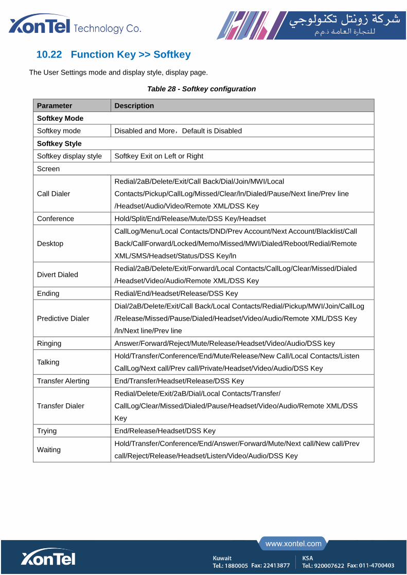
10.22 Function Key >> Softkey
The User Settings mode and display style, display page.
Table 28 - Softkey configuration
Parameter Description
Softkey Mode
Softkey mode Disabled and More,Default is Disabled
Softkey Style
Softkey display style Softkey Exit on Left or Right
Screen
Call Dialer
Redial/2aB/Delete/Exit/Call Back/Dial/Join/MWI/Local
Contacts/Pickup/CallLog/Missed/Clear/ln/Dialed/Pause/Next line/Prev line
/Headset/Audio/Video/Remote XML/DSS Key
Conference Hold/Split/End/Release/Mute/DSS Key/Headset
Desktop
CallLog/Menu/Local Contacts/DND/Prev Account/Next Account/Blacklist/Call
Back/CallForward/Locked/Memo/Missed/MWI/Dialed/Reboot/Redial/Remote
XML/SMS/Headset/Status/DSS Key/ln
Divert Dialed Redial/2aB/Delete/Exit/Forward/Local Contacts/CallLog/Clear/Missed/Dialed
/Headset/Video/Audio/Remote XML/DSS Key
Ending Redial/End/Headset/Release/DSS Key
Predictive Dialer
Dial/2aB/Delete/Exit/Call Back/Local Contacts/Redial/Pickup/MWI/Join/CallLog
/Release/Missed/Pause/Dialed/Headset/Video/Audio/Remote XML/DSS Key
/ln/Next line/Prev line
Ringing Answer/Forward/Reject/Mute/Release/Headset/Video/Audio/DSS key
Talking Hold/Transfer/Conference/End/Mute/Release/New Call/Local Contacts/Listen
CallLog/Next call/Prev call/Private/Headset/Video/Audio/DSS Key
Transfer Alerting End/Transfer/Headset/Release/DSS Key
Transfer Dialer
Redial/Delete/Exit/2aB/Dial/Local Contacts/Transfer/
CallLog/Clear/Missed/Dialed/Pause/Headset/Video/Audio/Remote XML/DSS
Key
Trying End/Release/Headset/DSS Key
Waiting Hold/Transfer/Conference/End/Answer/Forward/Mute/Next call/New call/Prev
call/Reject/Release/Headset/Listen/Video/Audio/DSS Key

10.23 Function Key >> Advanced
One key transfer: for example, set the memory key 4370. Press the memory key when talking with 4374 to
decide whether to call 4370 or transfer 4374 to 4370.
Select memory key function: for example, the phone set the memory key value to 4370. When 4370 calls, press
this key to hold the call or hang up.
Global Key Settings
Picture 131 - Global Key Settings
Programmable key Settings
Please refer to the Table 25 Softkey configuration
10.24 Application >> Manage Recording
See 7.3 Record for details of recording.
10.25 Security >> Web Filter
The user can set up a configuration management phone that allows only machines with a certain network
segment IP access.
Picture 132 - Web Filter settings
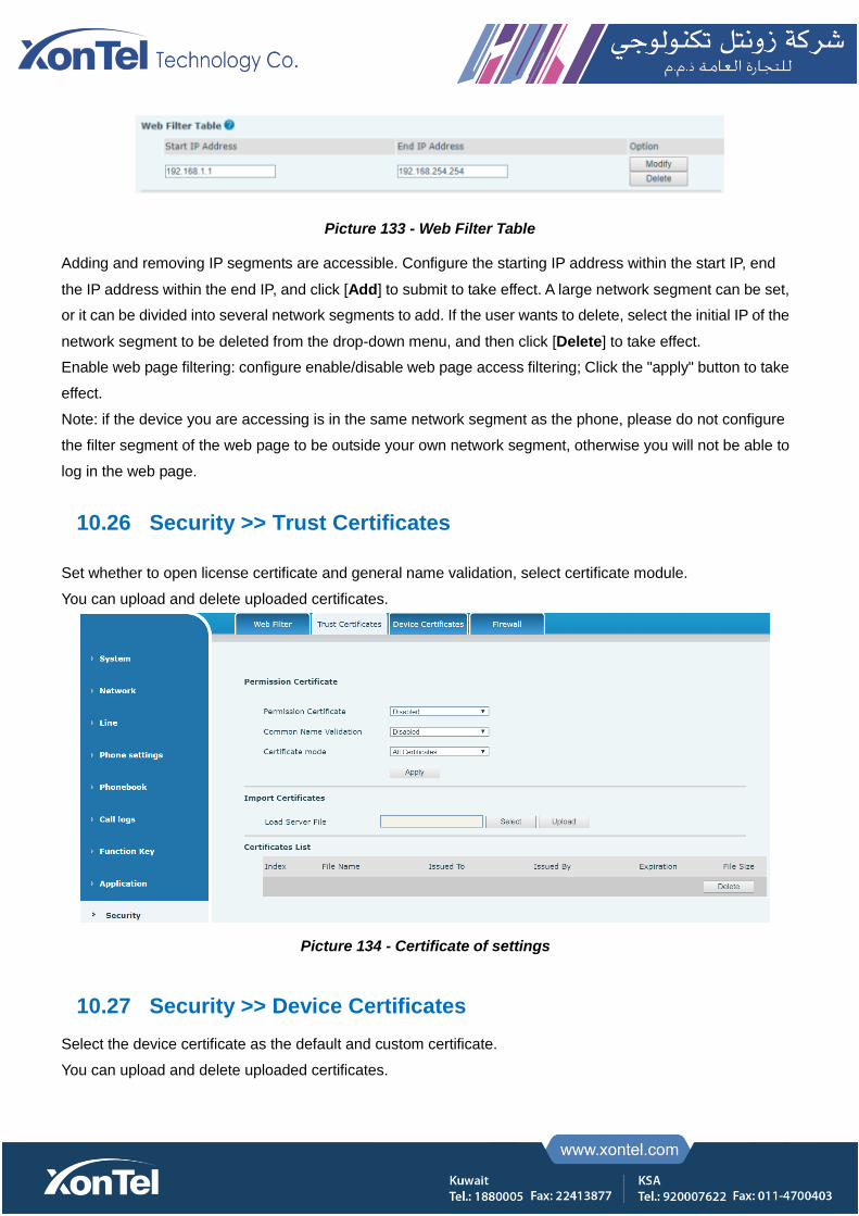
Picture 133 - Web Filter Table
Adding and removing IP segments are accessible. Configure the starting IP address within the start IP, end
the IP address within the end IP, and click [Add] to submit to take effect. A large network segment can be set,
or it can be divided into several network segments to add. If the user wants to delete, select the initial IP of the
network segment to be deleted from the drop-down menu, and then click [Delete] to take effect.
Enable web page filtering: configure enable/disable web page access filtering; Click the "apply" button to take
effect.
Note: if the device you are accessing is in the same network segment as the phone, please do not configure
the filter segment of the web page to be outside your own network segment, otherwise you will not be able to
log in the web page.
10.26 Security >> Trust Certificates
Set whether to open license certificate and general name validation, select certificate module.
You can upload and delete uploaded certificates.
Picture 134 - Certificate of settings
10.27 Security >> Device Certificates
Select the device certificate as the default and custom certificate.
You can upload and delete uploaded certificates.
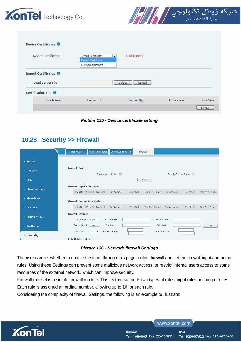
Picture 135 - Device certificate setting
10.28 Security >> Firewall
Picture 136 - Network firewall Settings
The user can set whether to enable the input through this page, output firewall and set the firewall input and output
rules. Using these Settings can prevent some malicious network access, or restrict internal users access to some
resources of the external network, which can improve security.
Firewall rule set is a simple firewall module. This feature supports two types of rules: input rules and output rules.
Each rule is assigned an ordinal number, allowing up to 10 for each rule.
Considering the complexity of firewall Settings, the following is an example to illustrate:
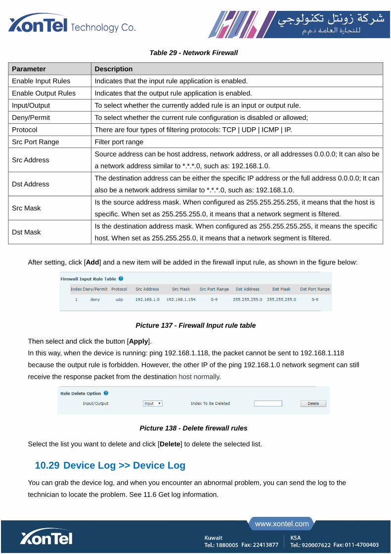
Table 29 - Network Firewall
Parameter Description
Enable Input Rules Indicates that the input rule application is enabled.
Enable Output Rules Indicates that the output rule application is enabled.
Input/Output To select whether the currently added rule is an input or output rule.
Deny/Permit To select whether the current rule configuration is disabled or allowed;
Protocol There are four types of filtering protocols: TCP | UDP | ICMP | IP.
Src Port Range Filter port range
Src Address Source address can be host address, network address, or all addresses 0.0.0.0; It can also be
a network address similar to *.*.*.0, such as: 192.168.1.0.
Dst Address The destination address can be either the specific IP address or the full address 0.0.0.0; It can
also be a network address similar to *.*.*.0, such as: 192.168.1.0.
Src Mask Is the source address mask. When configured as 255.255.255.255, it means that the host is
specific. When set as 255.255.255.0, it means that a network segment is filtered.
Dst Mask Is the destination address mask. When configured as 255.255.255.255, it means the specific
host. When set as 255.255.255.0, it means that a network segment is filtered.
After setting, click [Add] and a new item will be added in the firewall input rule, as shown in the figure below:
Picture 137 - Firewall Input rule table
Then select and click the button [Apply].
In this way, when the device is running: ping 192.168.1.118, the packet cannot be sent to 192.168.1.118
because the output rule is forbidden. However, the other IP of the ping 192.168.1.0 network segment can still
receive the response packet from the destination host normally.
Picture 138 - Delete firewall rules
Select the list you want to delete and click [Delete] to delete the selected list.
10.29 Device Log >> Device Log
You can grab the device log, and when you encounter an abnormal problem, you can send the log to the
technician to locate the problem. See 11.6 Get log information.
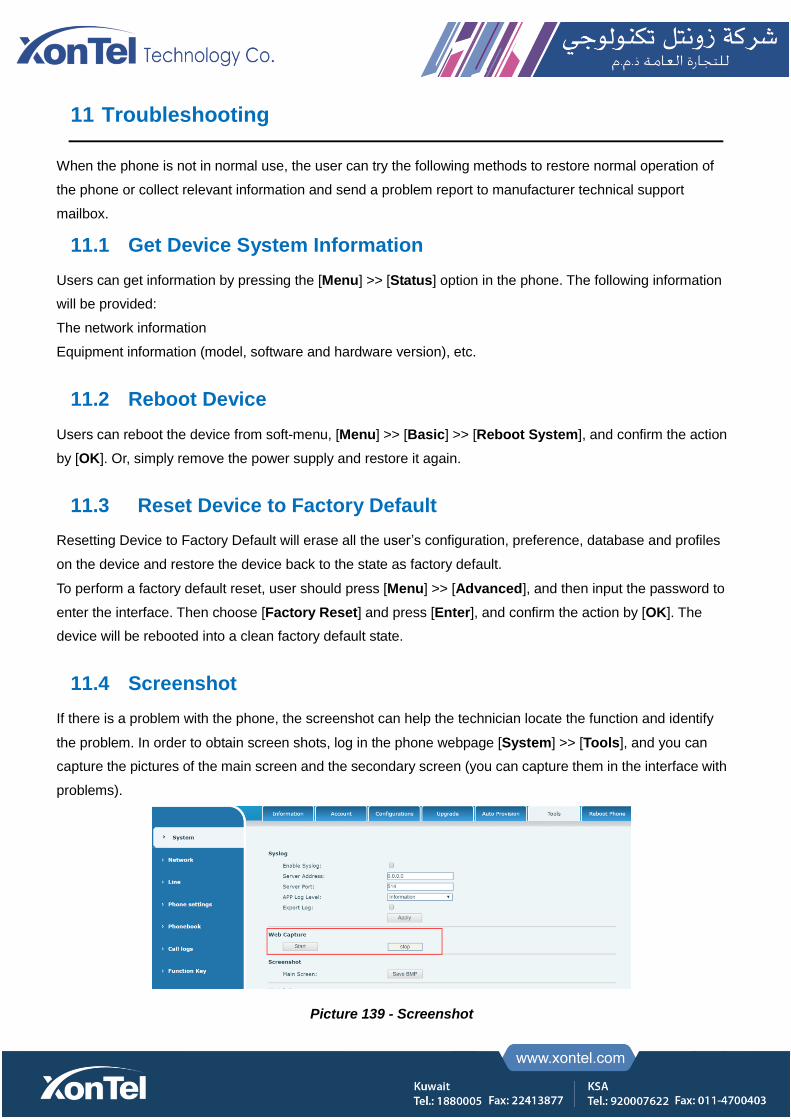
11 Troubleshooting
When the phone is not in normal use, the user can try the following methods to restore normal operation of
the phone or collect relevant information and send a problem report to manufacturer technical support
mailbox.
11.1 Get Device System Information
Users can get information by pressing the [Menu] >> [Status] option in the phone. The following information
will be provided:
The network information
Equipment information (model, software and hardware version), etc.
11.2 Reboot Device
Users can reboot the device from soft-menu, [Menu] >> [Basic] >> [Reboot System], and confirm the action
by [OK]. Or, simply remove the power supply and restore it again.
11.3 Reset Device to Factory Default
Resetting Device to Factory Default will erase all the user’s configuration, preference, database and profiles
on the device and restore the device back to the state as factory default.
To perform a factory default reset, user should press [Menu] >> [Advanced], and then input the password to
enter the interface. Then choose [Factory Reset] and press [Enter], and confirm the action by [OK]. The
device will be rebooted into a clean factory default state.
11.4 Screenshot
If there is a problem with the phone, the screenshot can help the technician locate the function and identify
the problem. In order to obtain screen shots, log in the phone webpage [System] >> [Tools], and you can
capture the pictures of the main screen and the secondary screen (you can capture them in the interface with
problems).
Picture 139 - Screenshot

11.5 Network Packets Capture
Sometimes it is helpful to dump the network packets of the device for issue identification. To get the packets
dump of the device, user needs to log in the device web portal, open page [System] >> [Tools] and click
[Start] in “Network Packets Capture” section. A pop-up message will be prompt to ask user to save the
capture file. User then should perform the relevant operations such as activating/deactivating line or making
phone calls and click [Stop] button in the web page when operation finished. The network packets of the
device during the period have been dumped to the saved file.
Picture 140 - Web capture
User may examine the packets with a packet analyzer or send it to manufacturer support mailbox.
11.6 Get Log Information
Log information is helpful when encountering an exception problem. In order to get the log information of the
phone, the user can log in the phone web page, open the page [Device log], click the [Start] button, follow
the steps of the problem until the problem appears, and then click the [End] button, [Save] to local analysis or
send the log to the technician to locate the problem.
11.7 Common Trouble Cases
Table 30 - Trouble Cases
Trouble Case Solution
Device could not boot up
1. The device is powered by external power supply via power adapter or PoE switch.
Please use standard power adapter provided by manufacturer or PoE switch met with
the specification requirements and check if device is well connected to power source.
2. If you saw “POST MODE” on the device screen, the device system image has been
damaged. Please contact location technical support to help you restore the phone
system.
Device could not register to a 1. Please check if device is well connected to the network. The network Ethernet cable
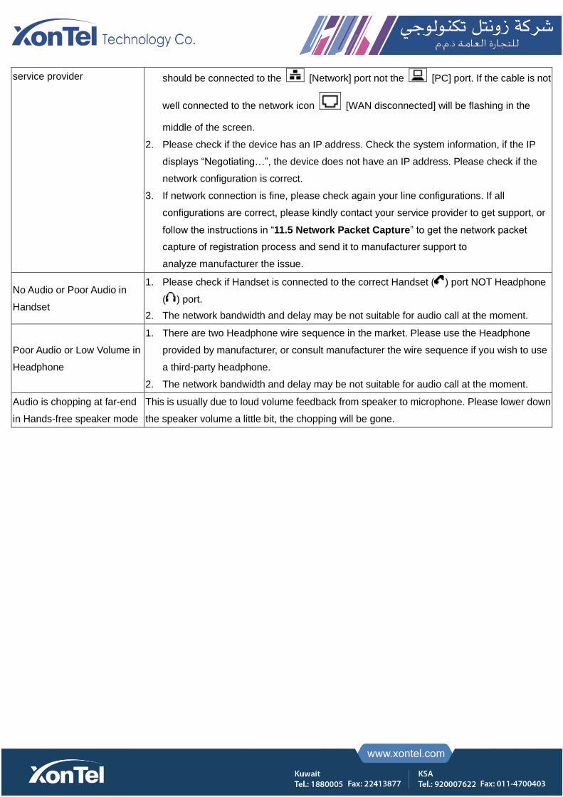
service provider should be connected to the [Network] port not the [PC] port. If the cable is not
well connected to the network icon [WAN disconnected] will be flashing in the
middle of the screen.
2. Please check if the device has an IP address. Check the system information, if the IP
displays “Negotiating…”, the device does not have an IP address. Please check if the
network configuration is correct.
3. If network connection is fine, please check again your line configurations. If all
configurations are correct, please kindly contact your service provider to get support, or
follow the instructions in “11.5 Network Packet Capture” to get the network packet
capture of registration process and send it to manufacturer support to
analyze manufacturer the issue.
No Audio or Poor Audio in
Handset
1. Please check if Handset is connected to the correct Handset ( ) port NOT Headphone
( ) port.
2. The network bandwidth and delay may be not suitable for audio call at the moment.
Poor Audio or Low Volume in
Headphone
1. There are two Headphone wire sequence in the market. Please use the Headphone
provided by manufacturer, or consult manufacturer the wire sequence if you wish to use
a third-party headphone.
2. The network bandwidth and delay may be not suitable for audio call at the moment.
Audio is chopping at far-end
in Hands-free speaker mode
This is usually due to loud volume feedback from speaker to microphone. Please lower down
the speaker volume a little bit, the chopping will be gone.