XS Catalogue - Nuaire · wide range of multipurpose wall, window and roof extract fans with...
16
029 2085 8200 112 SUPPLY & EXTRACT XS TECHNICAL INFORMATION XS EXTRACT FANS WIDE RANGE OF MULTIPURPOSE WALL, WINDOW AND ROOF EXTRACT FANS WITH OPTIONAL INTEGRATED CONTROLS.
Transcript of XS Catalogue - Nuaire · wide range of multipurpose wall, window and roof extract fans with...
029 2085 8200112
SUPPLY & EXTRACT
XS
TECHNIC AL INFORMATION
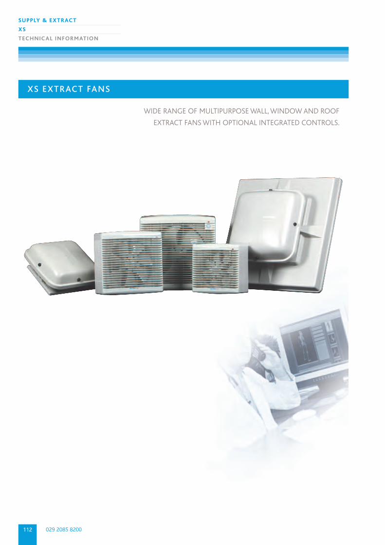
XS EXTRACT FANS
WIDE RANGE OF MULTIPURPOSE WALL, WINDOW AND ROOF
EXTRACT FANS WITH OPTIONAL INTEGRATED CONTROLS.
113
SUPPLY & EXTRACT
XS
TECHNIC AL INFORMATION
nuaire.co.uk
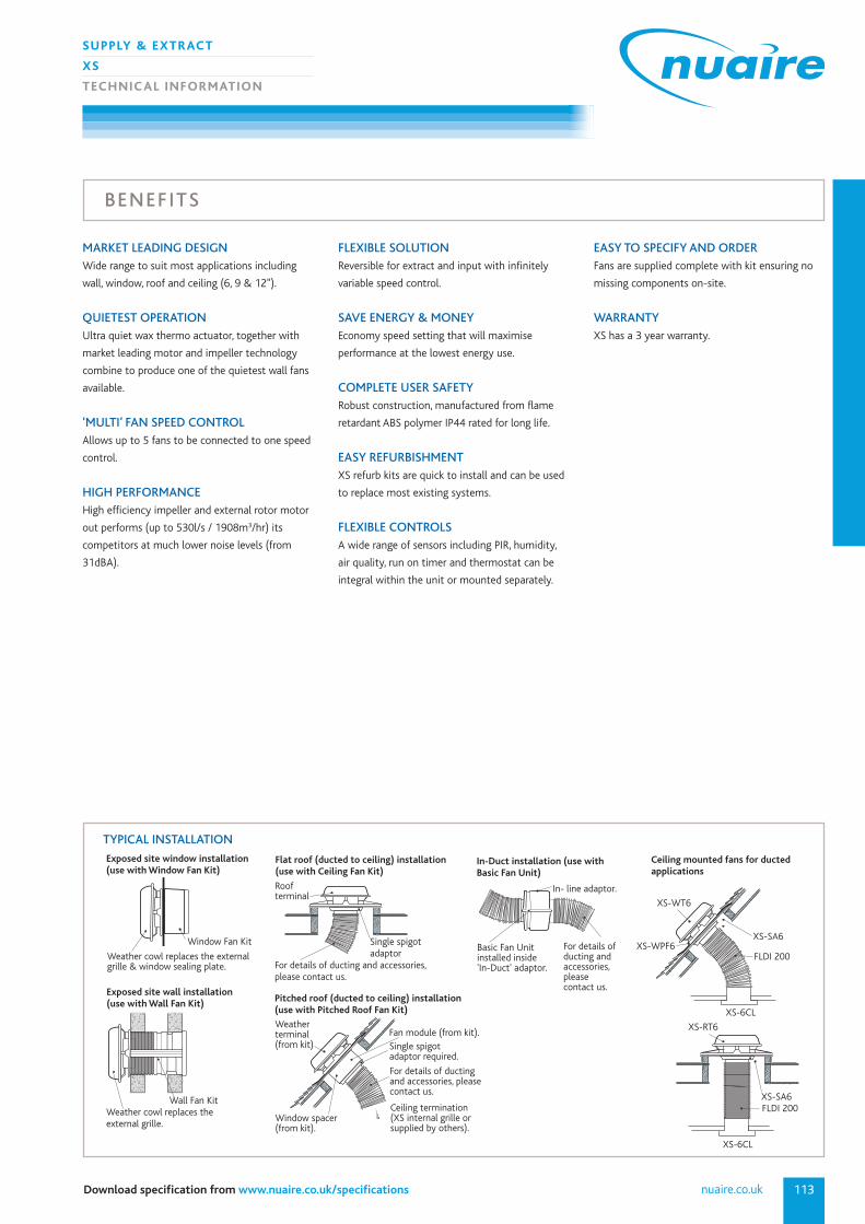
MARKET LEADING DESIGNWide range to suit most applications including
wall, window, roof and ceiling (6, 9 & 12").
QUIETEST OPERATIONUltra quiet wax thermo actuator, together with
market leading motor and impeller technology
combine to produce one of the quietest wall fans
available.
‘MULTI’ FAN SPEED CONTROLAllows up to 5 fans to be connected to one speed
control.
HIGH PERFORMANCE High efficiency impeller and external rotor motor
out performs (up to 530l/s / 1908m3/hr) its
competitors at much lower noise levels (from
31dBA).
FLEXIBLE SOLUTION Reversible for extract and input with infinitely
variable speed control.
SAVE ENERGY & MONEYEconomy speed setting that will maximise
performance at the lowest energy use.
COMPLETE USER SAFETY Robust construction, manufactured from flame
retardant ABS polymer IP44 rated for long life.
EASY REFURBISHMENT XS refurb kits are quick to install and can be used
to replace most existing systems.
FLEXIBLE CONTROLS A wide range of sensors including PIR, humidity,
air quality, run on timer and thermostat can be
integral within the unit or mounted separately.
EASY TO SPECIFY AND ORDER Fans are supplied complete with kit ensuring no
missing components on-site.
WARRANTY XS has a 3 year warranty.
BENEFITS
TYPICAL INSTALLATION
Exposed site wall installation(use with Wall Fan Kit)
Weather cowl replaces the external grille.
Wall Fan Kit
Weather cowl replaces the external grille & window sealing plate.
Window Fan Kit
Exposed site window installation(use with Window Fan Kit)
Single spigot adaptor
Flat roof (ducted to ceiling) installation(use with Ceiling Fan Kit)
Roof terminal
For details of ducting and accessories, please contact us.
Pitched roof (ducted to ceiling) installation(use with Pitched Roof Fan Kit)
Weather terminal(from kit)
Window spacer(from kit).
Single spigot adaptor required.
For details of ductingand accessories, please contact us.
Fan module (from kit).
Ceiling termination (XS internal grille or supplied by others).
XS-WT6
XS-WPF6XS-SA6
FLDI 200
XS-SA6
XS-6CL
XS-6CL
XS-RT6
FLDI 200
Ceiling mounted fans for ductedapplications
In-Duct installation (use with Basic Fan Unit)
In- line adaptor.
Basic Fan Unit installed inside'In-Duct' adaptor.
For details of ducting andaccessories, please contact us.
Download specification from www.nuaire.co.uk/specifications
029 2085 8200114
SUPPLY & EXTRACT
XS
TECHNIC AL INFORMATION
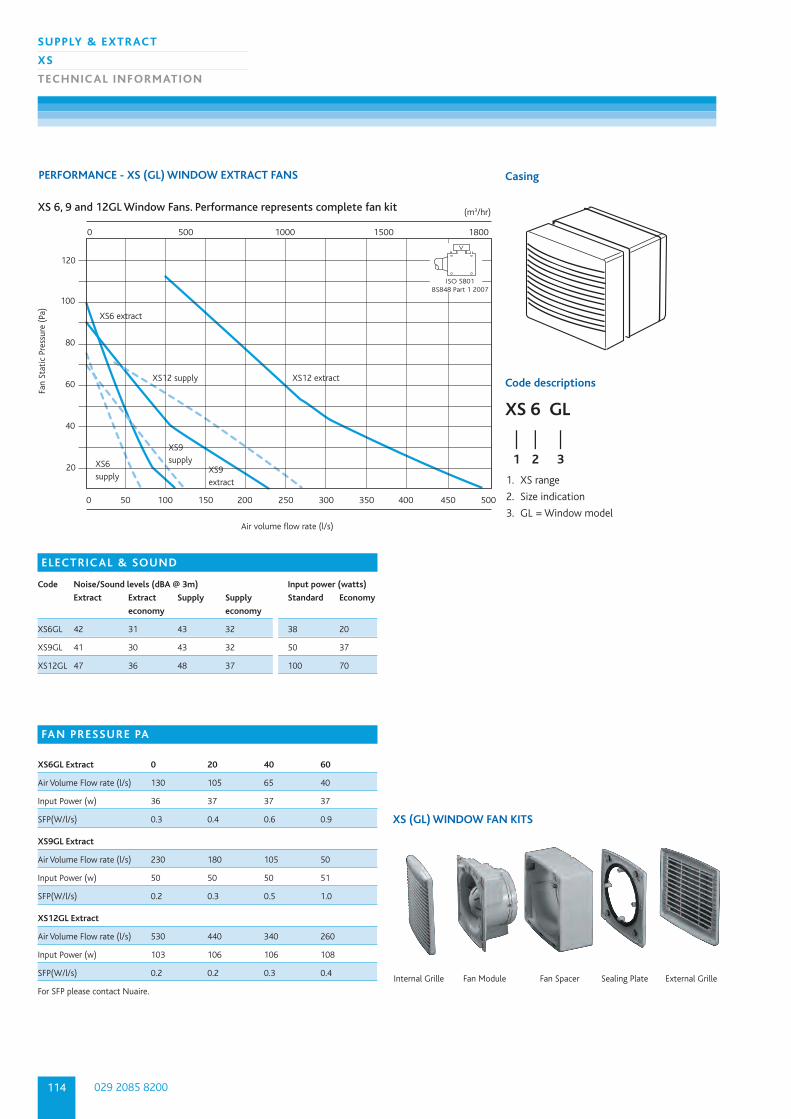
PERFORMANCE - XS (GL) WINDOW EXTRACT FANS Casing
1. XS range
2. Size indication
3. GL = Window model
Fan
Stat
ic P
ress
ure
(Pa)
Air volume flow rate (l/s)
XS 6, 9 and 12GL Window Fans. Performance represents complete fan kit
0 500 1000 1500 1800
0 50 100 150 200 250 300 350 400 450 500
(m3/hr)
XS12 supply XS12 extract
XS9 supply
XS9 extract
XS6 supply
XS6 extract
20
40
60
80
100
120
ISO 5801BS848 Part 1 2007
V
E
Code descriptions
XS 6 GL
| | |1 2 3
ELECTRICAL & SOUND
Code Noise/Sound levels (dBA @ 3m) Input power (watts)
Extract Extract Supply Supply Standard Economy
economy economy
XS6GL 42 31 43 32 38 20
XS9GL 41 30 43 32 50 37
XS12GL 47 36 48 37 100 70
FAN PRESSURE PA
XS6GL Extract 0 20 40 60
Air Volume Flow rate (l/s) 130 105 65 40
Input Power (w) 36 37 37 37
SFP(W/l/s) 0.3 0.4 0.6 0.9
XS9GL Extract
Air Volume Flow rate (l/s) 230 180 105 50
Input Power (w) 50 50 50 51
SFP(W/l/s) 0.2 0.3 0.5 1.0
XS12GL Extract
Air Volume Flow rate (l/s) 530 440 340 260
Input Power (w) 103 106 106 108
SFP(W/l/s) 0.2 0.2 0.3 0.4
For SFP please contact Nuaire.
XS (GL) WINDOW FAN KITS
Internal Grille Fan Module Fan Spacer External GrilleSealing Plate
115
SUPPLY & EXTRACT
XS
TECHNIC AL INFORMATION
nuaire.co.ukDownload specification from www.nuaire.co.uk/specifications
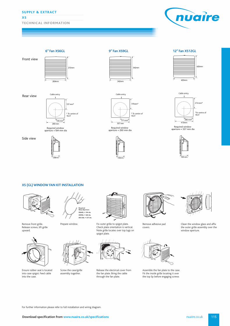
RequiredGlass Aperture
XS6GL = 184 dia
XS9GL = 260 dia
XS12GL = 337 dia
5
Remove front grille.Release screws, lift grilleupward.
Prepare window. Fix outer grille to spigot plate. Check plate orientation is vertical.Note grille locates over top lugs onspigot plate.
Remove adhesive pad covers.
Clean the window glass and affixthe outer grille assembly over thewindow aperture.
Ensure rubber seal is locatedinto case spigot. Feed cableinto the case.
For further information please refer to full installation and wiring diagram.
Screw the case/grille assembly together.
Release the electrical cover fromthe fan plate. Bring the cablethrough the fan plate.
Assemble the fan plate to the case.Fit the inside grille locating it overthe top lip before engaging screws
XS (GL) WINDOW FAN KIT INSTALLATION
6” Fan XS6GL 9” Fan XS9GL 12” Fan XS12GL
413mm
206 mm*
420mm
214 mm*
169 mm
420mm
Cable entry
*To centre of'duct'
Required window aperture = 337 mm dia
269 mm
134 mm*
269mm
137 mm*
128mm
272mm
Front view
Rear view
Side view
Cable entry
Required window aperture =184 mm dia
* To centre of'duct'
337 mm
171 mm*
342mm
175mm*
130mm
342mm
Cable entry
* To centre of'duct'
Required window aperture = 260 mm dia
029 2085 8200116
SUPPLY & EXTRACT
XS
TECHNIC AL INFORMATION
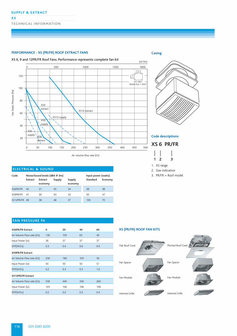
PERFORMANCE - XS (PR/FR) ROOF EXTRACT FANS Casing
1. XS range
2. Size indication
3. PR/FR = Roof model
Fan
Stat
ic P
ress
ure
(Pa)
Air volume flow rate (l/s)
XS 6, 9 and 12PR/FR Roof Fans. Performance represents complete fan kit
0 500 1000 1500 1800
0 50 100 150 200 250 300 350 400 450 500
(m3/hr)
XS12 supply
XS12 extract
XS9 supply
XS9 extract
XS6 supply
XS6 extract
20
40
60
80
100
120
ISO 5801BS848 Part 1 2007
V
Code descriptions
XS 6 PR/FR
| | |1 2 3
ELECTRICAL & SOUND
Code Noise/Sound levels (dBA @ 3m) Input power (watts)
Extract Extract Supply Supply Standard Economy
economy economy
XS6PR/FR 42 31 45 34 38 38
XS9PR/FR 41 30 43 32 50 37
XS12PR/FR 49 38 48 37 100 70
FAN PRESSURE PA
XS6PR/FR Extract 0 20 40 60
Air Volume Flow rate (l/s) 130 105 65 40
Input Power (w) 36 37 37 37
SFP(W/l/s) 0.3 0.4 0.6 0.9
XS9PR/FR Extract
Air Volume Flow rate (l/s) 230 180 105 50
Input Power (w) 50 50 50 51
SFP(W/l/s) 0.2 0.3 0.5 1.0
XS12PR/FR Extract
Air Volume Flow rate (l/s) 530 440 340 260
Input Power (w) 103 106 106 108
SFP(W/l/s) 0.2 0.2 0.3 0.4
XS (PR/FR) ROOF FAN KITS
Flat Roof Cowl
Fan Spacer
Fan Module
Internal Grille
Pitched Roof Cowl
Fan Spacer
Fan Module
Internal Grille
117
SUPPLY & EXTRACT
XS
TECHNIC AL INFORMATION
nuaire.co.ukDownload specification from www.nuaire.co.uk/specifications
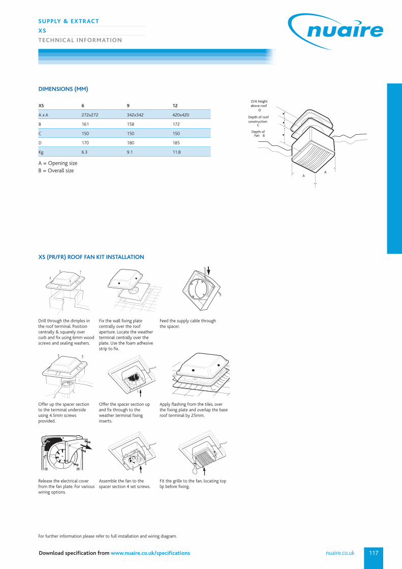
XS 6 9 12
A x A 272x272 342x342 420x420
B 161 158 172
C 150 150 150
D 170 180 185
Kg 6.3 9.1 11.8
A = Opening sizeB = Overall size
DIMENSIONS (MM)
1
A
B
C
A
Depth of roofconstruction
FanDepth of
O/A heightabove roof
D
XS (PR/FR) ROOF FAN KIT INSTALLATION
Drill through the dimples inthe roof terminal. Positioncentrally & squarely over curb and fix using 6mm woodscrews and sealing washers.
Fix the wall fixing plate centrally over the roof aperture. Locate the weatherterminal centrally over theplate. Use the foam adhesivestrip to fix.
Feed the supply cable throughthe spacer.
Offer up the spacer sectionto the terminal undersideusing 4.5mm screws provided.
Offer the spacer section up and fix through to the weather terminal fixing inserts.
Apply flashing from the tiles, overthe fixing plate and overlap the baseroof terminal by 25mm.
Release the electrical coverfrom the fan plate. For variouswiring options.
Assemble the fan to the spacer section 4 set screws.
Fit the grille to the fan, locating toplip before fixing.
For further information please refer to full installation and wiring diagram.
029 2085 8200118
SUPPLY & EXTRACT
XS
TECHNIC AL INFORMATION
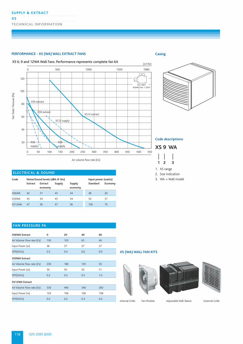
PERFORMANCE - XS (WA) WALL EXTRACT FANS Casing
1. XS range
2. Size indication
3. WA = Wall model
Fan
Stat
ic P
ress
ure
(Pa)
Air volume flow rate (l/s)
XS 6, 9 and 12WA Wall Fans. Performance represents complete fan kit (m3/hr)
XS12 supply
XS12 extract
XS9 supply
XS9 extract
XS6 supply
XS6 extract
20
40
60
80
100
120
0 500 1000 1500 1980
0 50 100 150 200 250 300 350 400 450 500 550
ISO 5801BS848 Part 1 2007
V
Code descriptions
XS 9 WA
| | |1 2 3
ELECTRICAL & SOUND
Code Noise/Sound levels (dBA @ 3m) Input power (watts)
Extract Extract Supply Supply Standard Economy
economy economy
XS6WA 42 31 45 34 38 20
XS9WA 45 34 45 34 50 37
XS12WA 47 36 47 36 100 70
FAN PRESSURE PA
XS6WA Extract 0 20 40 60
Air Volume Flow rate (l/s) 130 105 65 40
Input Power (w) 36 37 37 37
SFP(W/l/s) 0.3 0.4 0.6 0.9
XS9WA Extract
Air Volume Flow rate (l/s) 230 180 105 50
Input Power (w) 50 50 50 51
SFP(W/l/s) 0.2 0.3 0.5 1.0
XS12WA Extract
Air Volume Flow rate (l/s) 530 440 340 260
Input Power (w) 103 106 106 108
SFP(W/l/s) 0.2 0.2 0.3 0.4
XS (WA) WALL FAN KITS
Internal Grille Fan Module Adjustable Wall Sleeve External Grille
119
SUPPLY & EXTRACT
XS
TECHNIC AL INFORMATION
nuaire.co.ukDownload specification from www.nuaire.co.uk/specifications
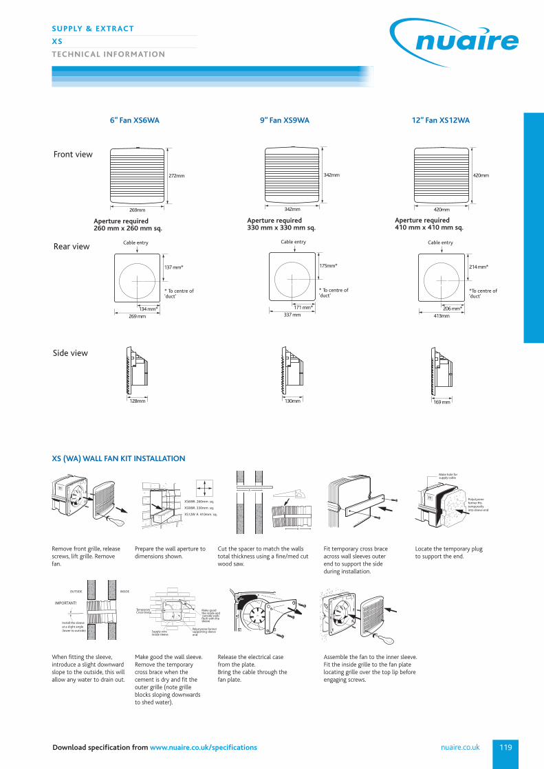
XS (WA) WALL FAN KIT INSTALLATION
2
3
XS6WA 260mm sq.
XS9WA 330mm sq.
XS12W A 410mm sq.
A
A
2
3
2
3
Polystyreneformer Þtstemporarilyinto sleeve end
Make hole for supply cable
2
3
Install the sleeveat a slight angle(lower to outside)
INSIDEOUTSIDE
X 2
3
IMPORTANT !
Polystyrene formersupporting sleeveend
Supply wireinside sleeve
Make goodthe inside and outside wallsßush with the sleeve
TemporaryCross brace
3
Remove front grille, releasescrews, lift grille. Removefan.
Prepare the wall aperture todimensions shown.
Cut the spacer to match the wallstotal thickness using a fine/med cutwood saw.
Fit temporary cross braceacross wall sleeves outerend to support the side during installation.
Locate the temporary plugto support the end.
When fitting the sleeve,introduce a slight downwardslope to the outside, this willallow any water to drain out.
Make good the wall sleeve.Remove the temporarycross brace when the cement is dry and fit theouter grille (note grilleblocks sloping downwardsto shed water).
Release the electrical casefrom the plate.Bring the cable through thefan plate.
Assemble the fan to the inner sleeve.Fit the inside grille to the fan platelocating grille over the top lip beforeengaging screws.
6” Fan XS6WA 9” Fan XS9WA 12” Fan XS12WA
413mm
206 mm*
420mm
214 mm*
169 mm
420mm
Cable entry
*To centre of'duct'
269 mm
134 mm*
269mm
137 mm*
128mm
272mm
Front view
Rear view
Side view
Cable entry
* To centre of'duct'
337 mm
171 mm*
342mm
175mm*
130mm
342mm
Cable entry
* To centre of'duct'
Aperture required 260 mm x 260 mm sq.
Aperture required 330 mm x 330 mm sq.
Aperture required 410 mm x 410 mm sq.
029 2085 8200120
SUPPLY & EXTRACT
XS
TECHNIC AL INFORMATION
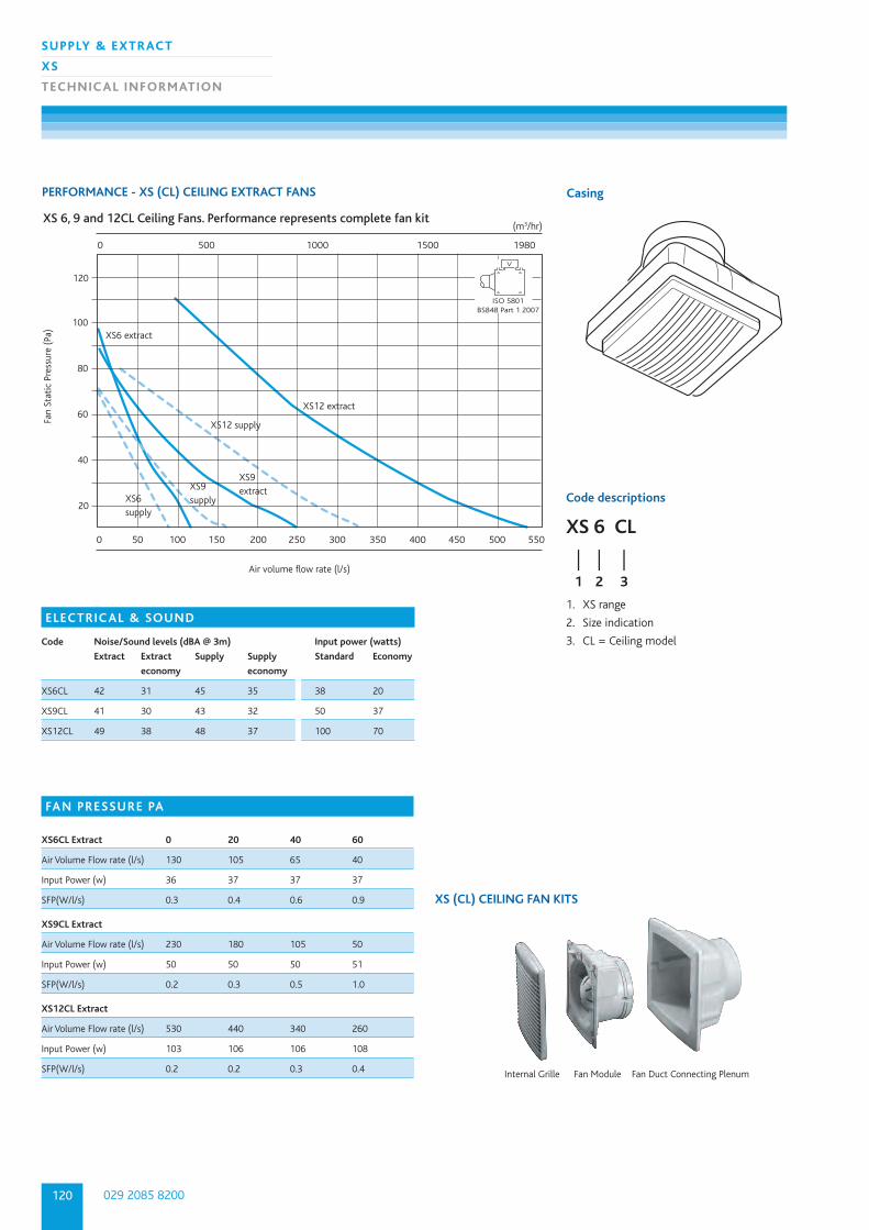
PERFORMANCE - XS (CL) CEILING EXTRACT FANS Casing
1. XS range
2. Size indication
3. CL = Ceiling model
Fan
Stat
ic P
ress
ure
(Pa)
Air volume flow rate (l/s)
XS 6, 9 and 12CL Ceiling Fans. Performance represents complete fan kit (m3/hr)
XS12 supply
XS12 extract
XS9 supply
XS9 extract
XS6 supply
XS6 extract
20
40
60
80
100
120
0 500 1000 1500 1980
0 50 100 150 200 250 300 350 400 450 500 550
ISO 5801BS848 Part 1 2007
V
Code descriptions
XS 6 CL
| | |1 2 3
ELECTRICAL & SOUND
Code Noise/Sound levels (dBA @ 3m) Input power (watts)
Extract Extract Supply Supply Standard Economy
economy economy
XS6CL 42 31 45 35 38 20
XS9CL 41 30 43 32 50 37
XS12CL 49 38 48 37 100 70
FAN PRESSURE PA
XS6CL Extract 0 20 40 60
Air Volume Flow rate (l/s) 130 105 65 40
Input Power (w) 36 37 37 37
SFP(W/l/s) 0.3 0.4 0.6 0.9
XS9CL Extract
Air Volume Flow rate (l/s) 230 180 105 50
Input Power (w) 50 50 50 51
SFP(W/l/s) 0.2 0.3 0.5 1.0
XS12CL Extract
Air Volume Flow rate (l/s) 530 440 340 260
Input Power (w) 103 106 106 108
SFP(W/l/s) 0.2 0.2 0.3 0.4
XS (CL) CEILING FAN KITS
Internal Grille Fan Module Fan Duct Connecting Plenum
121
SUPPLY & EXTRACT
XS
TECHNIC AL INFORMATION
nuaire.co.ukDownload specification from www.nuaire.co.uk/specifications
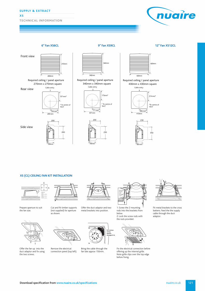
XS (CL) CEILING FAN KIT INSTALLATION
APERTURE6” Fan270mm x 270mm9” Fan340mm x 340mm12” Fan430mm x 430mm
A
A
Mounting Bracketwith threaded insert
For various wiringoptionssee page 9/10
Prepare aperture to suitthe fan size.
Cut and fit timber supports(not supplied) for apertureas shown.
Offer the duct adaptor and twometal brackets into position.
1: Screw the 2 mountingrods into the brackets frombelow. 2: Lock the screw rods withthe nuts provided.
Fit metal brackets to the crossbattens. Feed the the supplycable through the duct adaptor.
Offer the fan up into theduct adaptor and fix usingthe two screws.
Remove the electrical connection panel (top left).
Bring the cable through thefan late approx 150mm.
Fix the electrical connection beforeoffering up the internal grille. Note grille clips over the top edge before fixing.
6” Fan XS6CL 9” Fan XS9CL 12” Fan XS12CL
269 mm
134 mm*
269mm
137 mm*
128mm
272mm
Front view
Rear view
Side view
Cable entry
* To centre of'duct'
413mm
206 mm*
420mm
214 mm*
169 mm
420mm
Cable entry
*To centre of'duct'
337 mm
171 mm*
342mm
175mm*
130mm
342mm
Cable entry
* To centre of'duct'
Required ceiling / panel aperture 270mm x 270mm square
Required ceiling / panel aperture 430mm x 430mm square
Required ceiling / panel aperture 340mm x 340mm square
200 200 230
350250200
029 2085 8200122
SUPPLY & EXTRACT
XS
TECHNIC AL INFORMATION
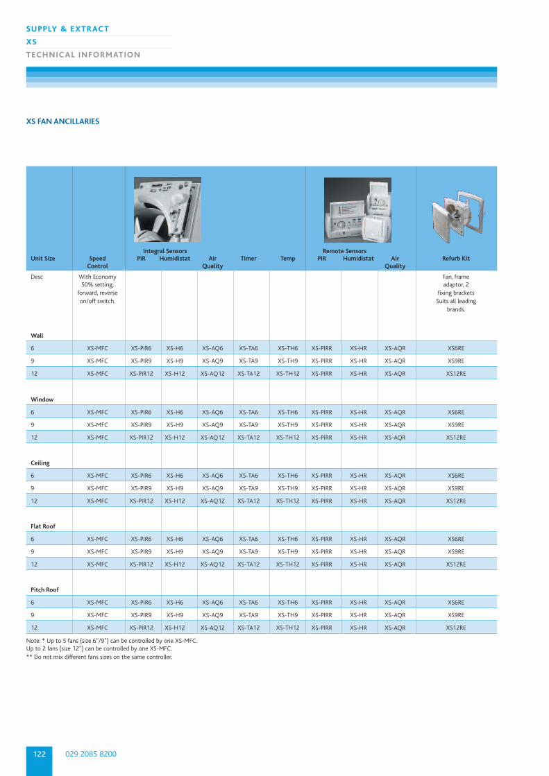
XS FAN ANCILLARIES
Integral Sensors Remote SensorsUnit Size Speed PIR Humidistat Air Timer Temp PIR Humidistat Air Refurb Kit
Control Quality Quality
Desc With Economy Fan, frame50% setting, adaptor, 2
forward, reverse fixing bracketson/off switch. Suits all leading
brands.
Wall
6 XS-MFC XS-PIR6 XS-H6 XS-AQ6 XS-TA6 XS-TH6 XS-PIRR XS-HR XS-AQR XS6RE
9 XS-MFC XS-PIR9 XS-H9 XS-AQ9 XS-TA9 XS-TH9 XS-PIRR XS-HR XS-AQR XS9RE
12 XS-MFC XS-PIR12 XS-H12 XS-AQ12 XS-TA12 XS-TH12 XS-PIRR XS-HR XS-AQR XS12RE
Window
6 XS-MFC XS-PIR6 XS-H6 XS-AQ6 XS-TA6 XS-TH6 XS-PIRR XS-HR XS-AQR XS6RE
9 XS-MFC XS-PIR9 XS-H9 XS-AQ9 XS-TA9 XS-TH9 XS-PIRR XS-HR XS-AQR XS9RE
12 XS-MFC XS-PIR12 XS-H12 XS-AQ12 XS-TA12 XS-TH12 XS-PIRR XS-HR XS-AQR XS12RE
Ceiling
6 XS-MFC XS-PIR6 XS-H6 XS-AQ6 XS-TA6 XS-TH6 XS-PIRR XS-HR XS-AQR XS6RE
9 XS-MFC XS-PIR9 XS-H9 XS-AQ9 XS-TA9 XS-TH9 XS-PIRR XS-HR XS-AQR XS9RE
12 XS-MFC XS-PIR12 XS-H12 XS-AQ12 XS-TA12 XS-TH12 XS-PIRR XS-HR XS-AQR XS12RE
Flat Roof
6 XS-MFC XS-PIR6 XS-H6 XS-AQ6 XS-TA6 XS-TH6 XS-PIRR XS-HR XS-AQR XS6RE
9 XS-MFC XS-PIR9 XS-H9 XS-AQ9 XS-TA9 XS-TH9 XS-PIRR XS-HR XS-AQR XS9RE
12 XS-MFC XS-PIR12 XS-H12 XS-AQ12 XS-TA12 XS-TH12 XS-PIRR XS-HR XS-AQR XS12RE
Pitch Roof
6 XS-MFC XS-PIR6 XS-H6 XS-AQ6 XS-TA6 XS-TH6 XS-PIRR XS-HR XS-AQR XS6RE
9 XS-MFC XS-PIR9 XS-H9 XS-AQ9 XS-TA9 XS-TH9 XS-PIRR XS-HR XS-AQR XS9RE
12 XS-MFC XS-PIR12 XS-H12 XS-AQ12 XS-TA12 XS-TH12 XS-PIRR XS-HR XS-AQR XS12RE
Note: * Up to 5 fans (size 6”/9”) can be controlled by one XS-MFC. Up to 2 fans (size 12”) can be controlled by one XS-MFC.** Do not mix different fans sizes on the same controller.
123
SUPPLY & EXTRACT
XS
TECHNIC AL INFORMATION
nuaire.co.ukDownload specification from www.nuaire.co.uk/specifications
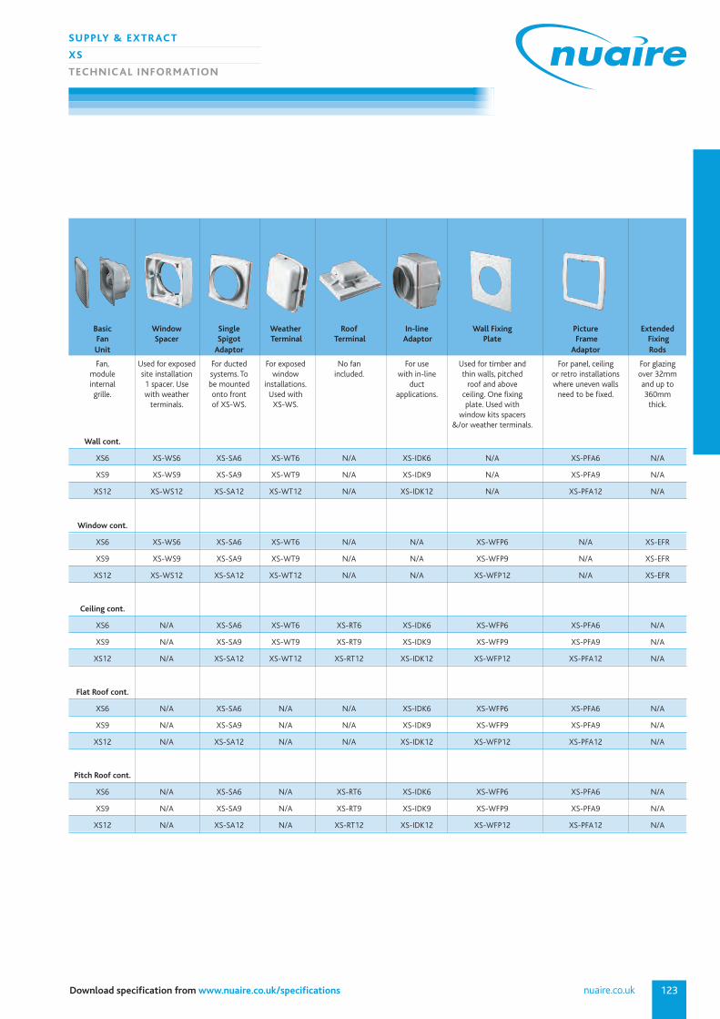
Basic Window Single Weather Roof In-line Wall Fixing Picture ExtendedFan Spacer Spigot Terminal Terminal Adaptor Plate Frame FixingUnit Adaptor Adaptor Rods
Fan, Used for exposed For ducted For exposed No fan For use Used for timber and For panel, ceiling For glazingmodule site installation systems. To window included. with in-line thin walls, pitched or retro installations over 32mminternal 1 spacer. Use be mounted installations. duct roof and above where uneven walls and up togrille. with weather onto front Used with applications. ceiling. One fixing need to be fixed. 360mm
terminals. of XS-WS. XS-WS. plate. Used with thick.window kits spacers
&/or weather terminals.
Wall cont.
XS6 XS-WS6 XS-SA6 XS-WT6 N/A XS-IDK6 N/A XS-PFA6 N/A
XS9 XS-WS9 XS-SA9 XS-WT9 N/A XS-IDK9 N/A XS-PFA9 N/A
XS12 XS-WS12 XS-SA12 XS-WT12 N/A XS-IDK12 N/A XS-PFA12 N/A
Window cont.
XS6 XS-WS6 XS-SA6 XS-WT6 N/A N/A XS-WFP6 N/A XS-EFR
XS9 XS-WS9 XS-SA9 XS-WT9 N/A N/A XS-WFP9 N/A XS-EFR
XS12 XS-WS12 XS-SA12 XS-WT12 N/A N/A XS-WFP12 N/A XS-EFR
Ceiling cont.
XS6 N/A XS-SA6 XS-WT6 XS-RT6 XS-IDK6 XS-WFP6 XS-PFA6 N/A
XS9 N/A XS-SA9 XS-WT9 XS-RT9 XS-IDK9 XS-WFP9 XS-PFA9 N/A
XS12 N/A XS-SA12 XS-WT12 XS-RT12 XS-IDK12 XS-WFP12 XS-PFA12 N/A
Flat Roof cont.
XS6 N/A XS-SA6 N/A N/A XS-IDK6 XS-WFP6 XS-PFA6 N/A
XS9 N/A XS-SA9 N/A N/A XS-IDK9 XS-WFP9 XS-PFA9 N/A
XS12 N/A XS-SA12 N/A N/A XS-IDK12 XS-WFP12 XS-PFA12 N/A
Pitch Roof cont.
XS6 N/A XS-SA6 N/A XS-RT6 XS-IDK6 XS-WFP6 XS-PFA6 N/A
XS9 N/A XS-SA9 N/A XS-RT9 XS-IDK9 XS-WFP9 XS-PFA9 N/A
XS12 N/A XS-SA12 N/A XS-RT12 XS-IDK12 XS-WFP12 XS-PFA12 N/A
029 2085 8200124
SUPPLY & EXTRACT
XS
TECHNIC AL INFORMATION
XS CONTROLS
INTEGRAL SENSORS
Fan PIR Humidistat Air Timer Temp
Size Quality
6 XS-PIR6 XS-H6 XS-AQ6 XS-TA6 XS-TH6
9 S-PIR9 XS-H9 XS-AQ9 XS-TA9 XS-TH9
12 XS-PIR12 XS-H12 XS-AQ12 XS-TA12 XS-TH12
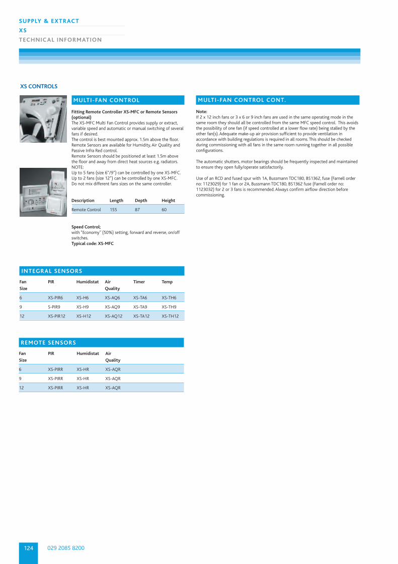
MULTI-FAN CONTROL
Fitting Remote Controller XS-MFC or Remote Sensors(optional)The XS-MFC Multi Fan Control provides supply or extract,variable speed and automatic or manual switching of severalfans if desired.The control is best mounted approx. 1.5m above the floor.Remote Sensors are available for Humidity, Air Quality andPassive Infra Red control.Remote Sensors should be positioned at least 1.5m abovethe floor and away from direct heat sources e.g. radiators.NOTE: Up to 5 fans (size 6”/9”) can be controlled by one XS-MFC. Up to 2 fans (size 12”) can be controlled by one XS-MFC.Do not mix different fans sizes on the same controller.
Description Length Depth Height
Remote Control 155 87 60
Speed Control; with “Economy” (50%) setting, forward and reverse, on/offswitches.Typical code: XS-MFC
REMOTE SENSORS
Fan PIR Humidistat Air
Size Quality
6 XS-PIRR XS-HR XS-AQR
9 XS-PIRR XS-HR XS-AQR
12 XS-PIRR XS-HR XS-AQR
MULTI-FAN CONTROL CONT.
Note:If 2 x 12 inch fans or 3 x 6 or 9 inch fans are used in the same operating mode in thesame room they should all be controlled from the same MFC speed control. This avoidsthe possibility of one fan (if speed controlled at a lower flow rate) being stalled by theother fan(s). Adequate make-up air provision sufficient to provide ventilation inaccordance with building regulations is required in all rooms. This should be checkedduring commissioning with all fans in the same room running together in all possibleconfigurations.
The automatic shutters, motor bearings should be frequently inspected and maintainedto ensure they open fully/operate satisfactorily.
Use of an RCD and fused spur with 1A, Bussmann TDC180, BS1362, fuse (Farnell orderno: 1123029) for 1 fan or 2A, Bussmann TDC180, BS1362 fuse (Farnell order no:1123032) for 2 or 3 fans is recommended. Always confirm airflow direction beforecommissioning.
125
SUPPLY & EXTRACT
XS
TECHNIC AL INFORMATION
nuaire.co.ukDownload specification from www.nuaire.co.uk/specifications
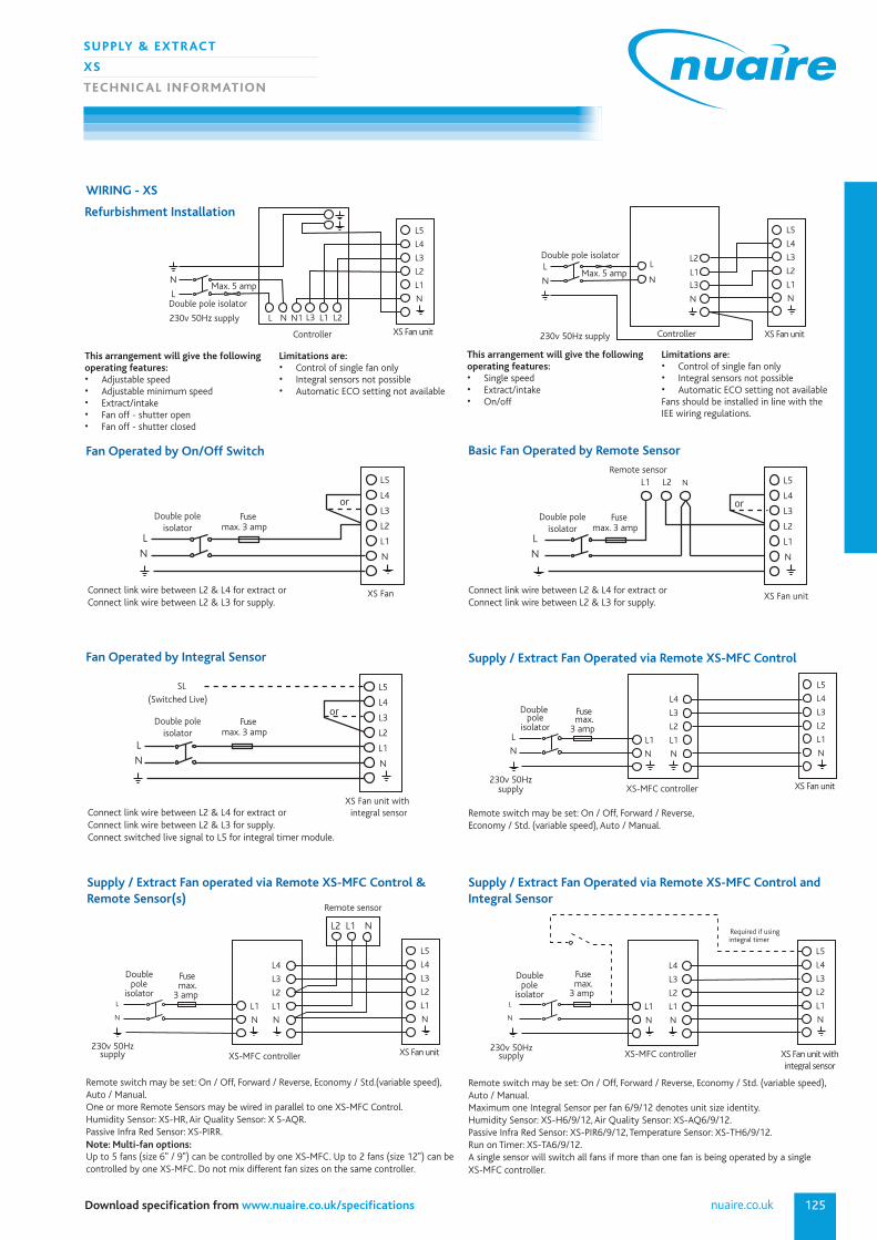
WIRING - XS
L5
L4
L3
L2
L1
N
or
N
XS Fan
L
Double poleisolator
Fusemax. 3 amp
L
Fan Operated by On/Off Switch
L5
L4
L3
L2
L1
N
or
L
N
integral sensor
R
SL(Switched Live)
XS Fan unit with
X
Double poleisolator
Fusemax. 3 amp
D
Fan Operated by Integral Sensor
XS-MFC controller
L5
L4
L3
L2
L1
N
L4
L3
L2
L1
N
L1
N
Double pole
isolator
Fusemax.
3 amp
L
N
XS Fan unit
230v 50Hzsupply
2
Supply / Extract Fan Operated via Remote XS-MFC Control
Connect link wire between L2 & L4 for extract orConnect link wire between L2 & L3 for supply.
Connect link wire between L2 & L4 for extract orConnect link wire between L2 & L3 for supply.Connect switched live signal to L5 for integral timer module.
Remote sensor
SL(
L5
L4
L3
L2
L1
N
or
L
N
L1 L2 N
XS Fan unit
D
Double poleisolator
Fusemax. 3 amp
Basic Fan Operated by Remote Sensor
Connect link wire between L2 & L4 for extract orConnect link wire between L2 & L3 for supply.
Remote switch may be set: On / Off, Forward / Reverse,Economy / Std. (variable speed), Auto / Manual.
XS-MFC controller
X
L5
L4
L3
L2
L1
N
L4
L3
L2
L1
N
L1
N
Double pole
isolator
L
N
Remote sensor
L2 L1 N
.
Fusemax.
3 amp
XS Fan unit
230v 50Hzsupply
2
Supply / Extract Fan operated via Remote XS-MFC Control &Remote Sensor(s)
Remote switch may be set: On / Off, Forward / Reverse, Economy / Std.(variable speed), Auto / Manual.One or more Remote Sensors may be wired in parallel to one XS-MFC Control.Humidity Sensor: XS-HR, Air Quality Sensor: X S-AQR.Passive Infra Red Sensor: XS-PIRR.Note: Multi-fan options:Up to 5 fans (size 6" / 9") can be controlled by one XS-MFC. Up to 2 fans (size 12") can becontrolled by one XS-MFC. Do not mix different fan sizes on the same controller.
L5
L4
L3
L2
L1
N
L4
L3
L2
L1
N
L1
N
L
N
Required if using integral timer
XS-MFC controller
L
Double pole
isolator
Fusemax.
3 amp
XS Fan unit withintegral sensor
230v 50Hzsupply
Supply / Extract Fan Operated via Remote XS-MFC Control andIntegral Sensor
Remote switch may be set: On / Off, Forward / Reverse, Economy / Std. (variable speed),Auto / Manual.Maximum one Integral Sensor per fan 6/9/12 denotes unit size identity.Humidity Sensor: XS-H6/9/12, Air Quality Sensor: XS-AQ6/9/12.Passive Infra Red Sensor: XS-PIR6/9/12, Temperature Sensor: XS-TH6/9/12.Run on Timer: XS-TA6/9/12.A single sensor will switch all fans if more than one fan is being operated by a single XS-MFC controller.
Refurbishment Installation
Controller
L5
L4
L3
L2
L1
N
L2L3 L1N1
L N
Double pole isolator
Max. 5 amp L
N
XS Fan unit
230v 50Hz supply
Controller
L5
L4
L3
L2
L1
N
L2
L3L1
L
N
Double pole isolator
Max. 5 amp L
N
XS Fan unit230v 50Hz supply
N
This arrangement will give the followingoperating features:• Adjustable speed• Adjustable minimum speed• Extract/intake• Fan off - shutter open• Fan off - shutter closed
Limitations are:• Control of single fan only• Integral sensors not possible• Automatic ECO setting not available
This arrangement will give the followingoperating features:• Single speed• Extract/intake• On/off
Limitations are:• Control of single fan only• Integral sensors not possible• Automatic ECO setting not availableFans should be installed in line with the IEE wiring regulations.
029 2085 8200126
SUPPLY & EXTRACT
XS
TECHNIC AL INFORMATION
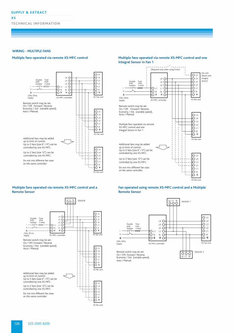
WIRING - MULTIPLE FANS
Remote switch may be set: On / Off, Forward / Reverse,Economy / Std. (variable speed), Auto / Manual.
Additional fans may be addedup to limit of control:Up to 5 fans (size 6" / 9") can be controlled by one XS-MFC.
Up to 2 fans (size 12") can be controlled by one XS-MFC.
Do not mix different fan sizeson the same controller
XS-MFC controller
L5
L4
L3
L2
L1
N
L4
L3
L2
L1
N
L1
N
Double poleisolator
Fusemax. 3 amp
L
N
XS Fan unit 230v 50Hzsupply
L5
L4
L3
L2
L1
N
XS Fan unit
L5
L4
L3
L2
L1
N
XS Fan unit
Multiple fans operated via remote XS-MFC control
Remote switch may be set: On / Off, Forward / Reverse,Economy / Std. (variable speed), Auto / Manual.
XS-MFC controller
L5
L4
L3
L2
L1
N
L4
L3
L2
L1
N
L1
N
L
N
XS Fan unit
SENSOR
230v 50 Hzsupply
L5
L4
L3
L2
L1
N
XS Fan unit
L2 L1 N
Additional fans may be addedup to limit of control:Up to 5 fans (size 6" / 9") can be controlled by one XS-MFC.
Up to 2 fans (size 12") can becontrolled by one XS-MFC.
Do not mix different fan sizeson the same controller.
L5
L4
L3
L2
L1
N
XS Fan unit
Double poleisolator
Fusemax. 3 amp
Multiple fans operated via remote XS-MFC control and aRemote Sensor
Forwa
N
A
Remote switch may be set: On / Off, Forward / Reverse,Economy / Std. (variable speed), Auto / Manual.
Additional fans may be addedup to limit of control:Up to 5 fans (size 6" / 9") can be controlled by one XS-MFC.
Up to 2 fans (size 12") can becontrolled by one XS-MFC.
Do not mix different fan sizeson the same controller .
XS-MFC controller
(Required only when using Timer)
L5
L4
L3
L2
L1
N
L4
L3
L2
L1
N
L1
N
L
N
XS Fan unit 230v 50Hzsupply
L5
L4
L3
L2
L1
N
L5
L4
L3
L2
L1
N
Multiple fans operated via remote XS-MFC control and one Integral Sensor in Fan 1
Forwa
N
Double poleisolator
Fusemax. 3 amp
XS Fan unit
XS Fan unit
D
Fan unit(fitted withintegral sensor)
Multiple fans operated via remote XS-MFC control and oneIntegral Sensor in Fan 1
N
A
Remote switch may be set: On / Off, Forward / Reverse,Economy / Std. (variable speed), Auto / Manual.
XS-MFC controller
SENSOR 1
L5
L4
L3
L2
L1
N
L4
L3
L2
L1
N
L1
N
L
N
XS Fan unit 230v 50Hzsupply
L2 L1 N
SENSOR 2
L2 L1 N
Double poleisolator
Fusemax. 3 amp
D
Fan operated using remote XS-MFC control and a MultipleRemote Sensor
127
SUPPLY & EXTRACT
XS
TECHNIC AL INFORMATION
nuaire.co.ukDownload specification from www.nuaire.co.uk/specifications
FAN DESCRIPTIONThe extract fan/s shall be located in the positions indicated on the drawings and
in accordance with the relevant fan schedule.
The fan shall be of the XS type and shall be supplied complete with integrated low
loss radial backdraught shutter, silent operation via a thermo actuator, room side
grille, connection kit and external louvre/roof cowl to suit the particular application.
The high efficiency, low noise axial flow impeller shall be directly driven by an
external rotor motor featuring enclosure protection to IP 44, class B winding
insulation and maintenance free ball bearings. All models shall be suitable for
air over motor temperatures of up to 60°C and 95% R.H (non-condensing).
The motor and impeller shall be dynamically balanced as an assembly.
Fan casing, impeller and shutter shall be manufactured from UV stabilised
ABS polymer. All models shall include an economy/high efficiency setting facility
and are dove grey in colour.
The fan shall be provided complete with integrated or remote controls as
detailed in the schedule and as described below.
Where indicated the fans shall be interlinked and controlled from 1No. controller
(up to 5 fans sizes 6 & 9, up to 3 fans size 12).
Fans shall be reversible via reversing switch on XS-MFC fan controller.
Fan to have a manufacturers 3 year warranty.
Fan to be of the XS type as manufactured by Nuaire Ltd.
FAN CONTROL OPTIONThe fan shall be provided with either integrated sensor to activate the fan or one
of the remote options:
INTEGRATED CONTROL OPTIONS:• PIR (passive infra-red) movement detector (includes run-on timer), 2-40 mins
• Humidity sensor (includes run-on timer), 30-90% RH - 2-40 mins RT
• Air quality sensor (includes run-on timer), 2-40 mins
• Run-on timer (all adjustable between 2-40 mins)
• Temperature sensor (includes run-on timer), 5-35ºC (fixed 2mm overrun)
REMOTE CONTROL OPTIONS:• PIR (passive infra-red) movement detector (includes run-on timer), 2-40 mins
• Humidity sensor (includes run-on timer), 30-90% RH - 2-40 mins RT
• Air quality sensor (includes run-on timer), 2-40 mins RT
• Anti-tamper security strap.
• XS-MFC controller incorporating economy switch, reversing switch and rotary
speed control –
1No. XS-MFC controller may be used to control up to 5 fans.
Fan, integrated controls or associated sensors/controllers shall be as
manufactured by Nuaire Ltd all with a 3 years warranty.
The manufacturer’s recommendations should be observed at all times.
CONSULTANTS SPECIFICATION


![S90 XS/S70 XS Editor VST Owner's Manual - Yamaha · Starting the S90 XS/S70 XS Editor VST S90 XS/S70 XS Editor VST Owner’s Manual 6 13. In Quick Set Up, select [1] or [2]. nFor](https://static.fdocuments.in/doc/165x107/5fa5d7be5c20e054d9711161/s90-xss70-xs-editor-vst-owners-manual-yamaha-starting-the-s90-xss70-xs-editor.jpg)