XR BOOK PAGES 1-41 - nasscoinc.com · 2. Floor Seals, Wipers, Splash Curtains, Squeegees or...
47
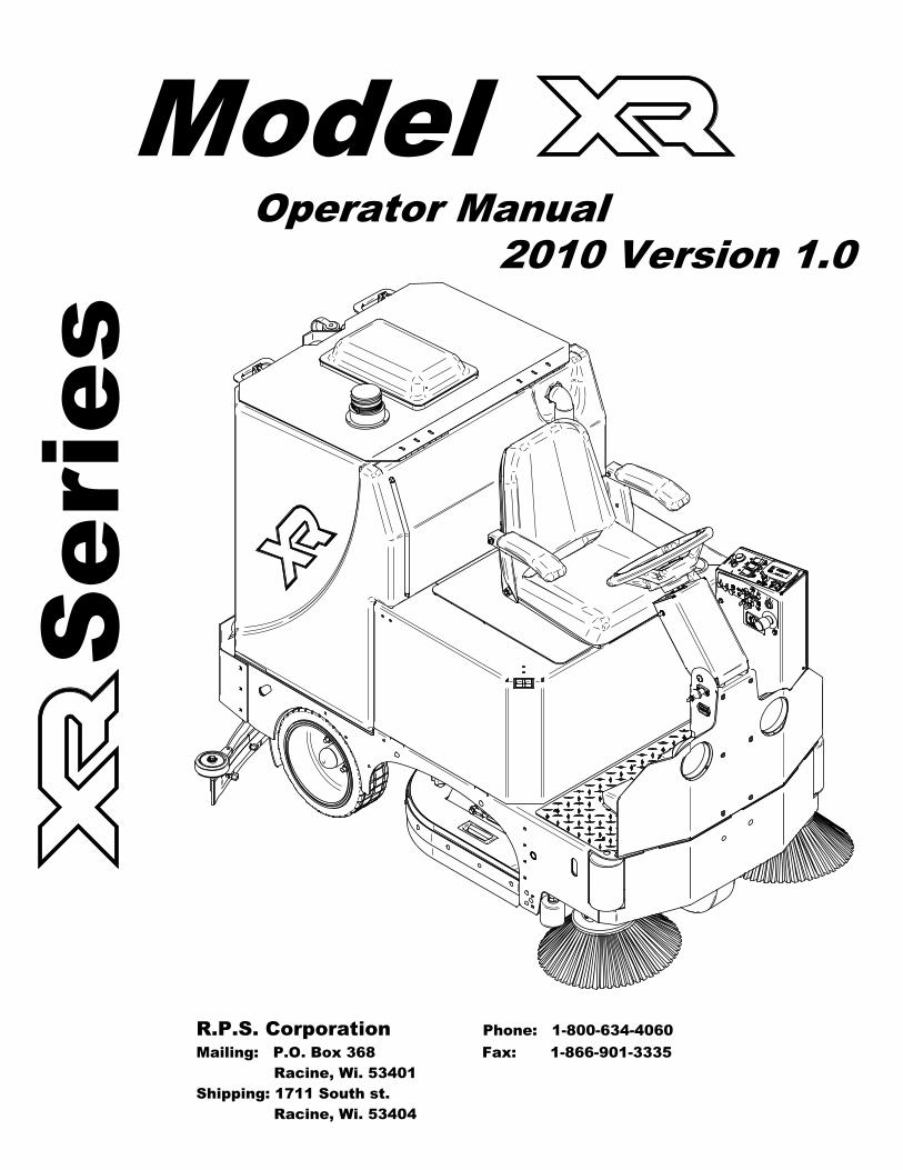
s e i r e S Operator Manual Model 2010 Version 1.0 R.P.S. Corporation Phone: 1-800-634-4060 Mailing: P.O. Box 368 Fax: 1-866-901-3335 Racine, Wi. 53401 Shipping: 1711 South st. Racine, Wi. 53404
Transcript of XR BOOK PAGES 1-41 - nasscoinc.com · 2. Floor Seals, Wipers, Splash Curtains, Squeegees or...
seireS
Operator ManualModel
2010 Version 1.0
R.P.S. Corporation Phone: 1-800-634-4060Mailing: P.O. Box 368 Fax: 1-866-901-3335 Racine, Wi. 53401Shipping: 1711 South st. Racine, Wi. 53404
HOW TO USE THIS MANUALThis manual contains the following sections:
- HOW TO USE THIS MANUAL - SAFETY - OPERATIONS - MAINTENANCE - PARTS LIST
The HOW TO USE THIS MANUAL section will tellyou how to find important information forordering correct repair parts.
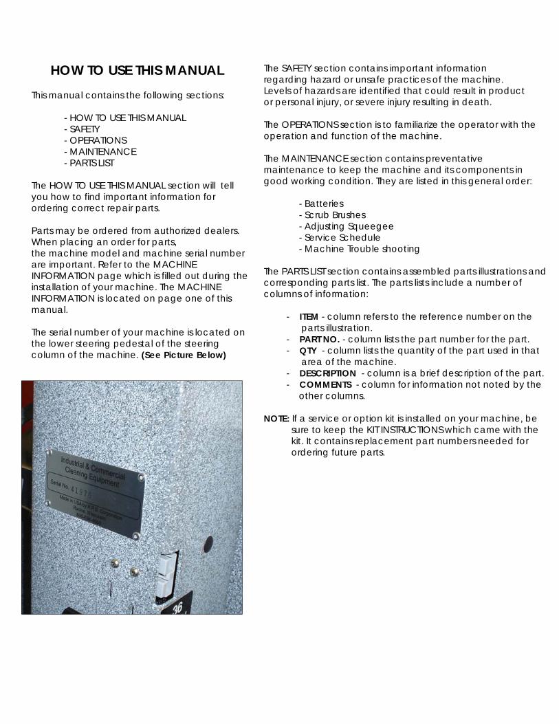
Parts may be ordered from authorized dealers.When placing an order for parts,the machine model and machine serial numberare important. Refer to the MACHINEINFORMATION page which is filled out during theinstallation of your machine. The MACHINEINFORMATION is located on page one of thismanual.
The serial number of your machine is located onthe lower steering pedestal of the steeringcolumn of the machine. (See Picture Below)
The SAFETY section contains important informationregarding hazard or unsafe practices of the machine.Levels of hazards are identified that could result in productor personal injury, or severe injury resulting in death.
The OPERATIONS section is to familiarize the operator with theoperation and function of the machine.
The MAINTENANCE section contains preventativemaintenance to keep the machine and its components ingood working condition. They are listed in this general order:
- Batteries - Scrub Brushes - Adjusting Squeegee - Service Schedule - Machine Trouble shooting
The PARTS LIST section contains assembled parts illustrations andcorresponding parts list. The parts lists include a number ofcolumns of information:
- ITEM - column refers to the reference number on the parts illustration. - PART NO. - column lists the part number for the part. - QTY - column lists the quantity of the part used in that area of the machine. - DESCRIPTION - column is a brief description of the part. - COMMENTS - column for information not noted by the other columns.
NOTE: If a service or option kit is installed on your machine, be sure to keep the KIT INSTRUCTIONS which came with the kit. It contains replacement part numbers needed for ordering future parts.

STANDARD WARRANTY POLICY (RPS Corporation) RPS Corporation warrants its machines, parts and accessories to be free of manufacturer’s defects for the periods specified below. Warranty will be granted at the sole discretion of RPS Corporation and is subject to final claim and parts review by R.P.S. Corporation and its vendors. This policy is effective January 1, 2010 and is subject to change on production units at a future date. COVERAGE, EXCLUSIONS AND LIMITATIONS: Coverage: All Models sold (Sweepers, Scrubbers, Burnishers) Parts: 36 months / 1,500 hours on “Power On” hour meter Labor: 12 months Travel: 3 months (150 mile maximum) Poly Tanks: 7 Years OEM Parts: 3 months Validity: Fully completed Machine Delivery Form (online or fax) is on record at RPS. Limitation: Warranty will begin on date of machine installation to end-user or 6 months
after shipment from RPS Corp to the distributor if unsold at that time. This warranty includes all parts on the machine except normal wear parts. Some of these exceptions are:
1. Any Brooms, Brushes, Pads or Pad Drivers including Center Clip Retainers 2. Floor Seals, Wipers, Splash Curtains, Squeegees or Gaskets. 3. Filters, Dust Collection Bags or Screens 4. The safety pins design to fail in shear, which are a fail-safe device 5. Belts, Hoses or Tubing. 6. Caster Wheels, Tires or internal tire tubes. 7. Vacuum motors with evidence of water/foam passage or more than 450
hours 8. Lights (Strobe, Headlights or bulbs). 9. The Batteries (see below). NOT COVERED: Routine maintenance, adjustments or parts damaged from
abuse, neglect, improper use of the machine, or lack of scheduled “daily, weekly, monthly” maintenance in accordance with our published PM Sheets.
POLY TANKS: 7 Years Coverage against leakage due to manufacturer’s defect in materials or workmanship. NOTE: Freight coverage for 3-Years under the parts section of warranty. BATTERIES: Warranted through battery manufacturer for One (1) Year (prorated) from the date of delivery. The battery manufacturer approves or denies the warranty coverage after analysis. We rely on solely on their review. NOTE NOT COVERED: Damage from lack of water, failure to use OEM charger, or non-distilled water.

Machine InformationMachine delivery formMachine specificationsCommon wear parts/scrub brushesSafety messages!!Safety precautions!!Machine controls and featuresLcd screen menu displaysMachine setupAttaching squeegeeAdjusting squeegeeLeveling scrub deckAttaching brushesAdjusting shroudsAdjusting cylindrical side wipersSolution systemVacuum systemMachine operationDraining recovery & solution tanksRec. Float shut offDrain saverStandard battery chargingOptional battery chargingOn-Board charger operator manualChanging batteriesSide broom systemOverhead guardHD Side doorsOn-board SoapSpray hoseVac wandDiffuser exhaust barStainless steel recovery tankStainless steel solution tankIndustrial batteryRemovable battery boxOn-Board soapSpray hoseVac wandMaintenance & storing machinePreventative maintenance recordsTroubleshooting central command iiTroubleshooting
Page 1Page 2Page 3Page 4Page 5Page 6Page 7-8Page 9Page 10Page 11Page 12Page 13Page 14Page 15Page 16Page 17Page 18Page 19-21Page 22Page 23Page 23Page 24Page 25Page 26-28Page 29Page 30Page 31Page 31Page 31Page 31Page 32Page 32Page 32Page 32Page 32Page 32Page 33Page 33Page 33Page 34-35Page 36-37Page 38-39Page 40-41
Table of Contents

PAGE 1
Machine InformationModel number_____________________________________________________________
Serial number:______________________________________________________________
Installation date:___________________________________________________________
Installing dealer:____________________________________________________________
Dealer contact: ___________________________________________________________
Address:___________________________________________________________________
City, state, zip: _____________________________________________________________
Phone number:_____________________________________________________________
To register for warranty, fax your warranty registration form today! Fax # (886)-632-6961
This operator and parts manual should be considered a permanent part of the unit and shouldremain with the unit at all times. This operator and parts manual covers all the XR series scrubbers.You may find descriptions and features that are not on your particular model. The informationand specifications included in this publication were in effect at the time of printing.R.P.S. Corporation reserves the right to make changes without notice incurring any obligation.

1-800-634-4060 Machine Install / Warranty Registration www.factorycat.com
Installing Dealer: Installed By:
Location: (City, State): Install Date:
End-User Company Name End-User Contact:
Address: City/State: Zip
Phone: Fax: Email:
Model: Serial #: Hour Meter:
BUYER’S REPRESENTATIVE HAS RECEIVED INSTRUCTION IN PROPER OPERATION OF THE FOLLOWING CONTROLS AND FEATURES:
SCRUBBERS
Filling solution tank, Solution tank sight tube, Solution drain hose or valve for flushing and freezing conditions
Adjusting controls & operation, Double scrubbing, Squeegee lift delay, vacuum switch (horn honking) and vacuum timer
Recovery tank draining & cleaning, vacuum screen removal and cleaning, drain saver basket emptied.
Shroud and pad/brush removal and installation
Side Wiper and Curtain adjustment and maintenance for water control
Solution valve and filter operation (removal and cleaning)
LCD display operation, 4 hour meters (key switch, brush, traction drive, vacuum)
Tank tilt back feature, only when both tanks are fully drained
Squeegee hose removal and checking for clogs
BURNISHERS
Train and have customer demonstrate proper removal and replacement of burnishing pad
Pad pressure gauge and proper operating range to avoid tripping the circuit breaker
SWEEPERS
Demonstrate proper removal and replacement of main broom and side brooms
Method for cleaning the dust filter, empting out the debris hopper and correct installation
Correct operation of the main broom and side broom levers, and understands to park with brushes in UP position
Trained on the “Wet-Sweep” bypass door and not to operate through standing water
ALL MACHINES
Checking battery electrolyte level and confirm monthly check that battery terminals are tight
Parking brake override
Charging operation and customer understands batteries have limited “cycles” and recharging = 1 cycle
Seat and steering wheel adjustment
Customer has read and understands the list of WARNINGS in the Operator manual
Battery and Machine Maintenance Guide posters hung up and reviewed
Manufacturer’s website is a good source of information and sign up for quarterly newsletters
In addition to the above items the buyers representative has received the operator’s manual and been advised to read the manual before
operating the machine.
Installed By (print) Signature
Buyers Representative (print) Signature
Buyer agrees to pay for any repairs, adjustments, or secondary training that manufacturer determines is excluded from the warranty.
COMPLETE AND FAX FORM TO 1-866-632-6961 or online www.factorycat.com

PAGE 3
SPECS Disk Cylindrical BODY CONSTRUCTION Tank Material: (3/8”) Roto-Poly (3/8”) Roto-Poly Frame Construction: 3/16” Coated Steel 3/16” Coated Steel Front Wheel: 12” x 4” 12” x 4” Rear Wheel: (2) 14” x 5” (2) 14” x 5” Body Dimensions (L x W x H): 69” x 36” x 59” 69” x 36” x 59” Width (squeegee): 46”, 53” or 60” 46”, 53” or 60” Weight (w/out batteries): 1,230 pounds 1,230 pounds Weight (w/ standard batteries): 1,950 pounds 1,950 pounds
BRUSH/PAD SYSTEM Brush/Pad Diameter: XR-34D - (2) 17 inches XR-34C - (2) 32” x 7.0” XR-40D - (2) 20 inches XR-40C - (2) 42” x 7.0” XR-46C - (2) 44” x 7.0” Motor Power (standard): (2) 1.5 hp / 270 rpm (2) 1.5 hp /750 rpm Brush Pressure: 0-350 pounds 0-350 pounds Brush Pressure Settings: (1-5) automatic (1-5) automatic Actuator Rating: 500 lbs. 500 lbs.
BATTERY SYSTEM System Voltage: 36 volts 36 volts Battery AH Rating (Standard): (6) 325 AH (6) 325 AH Battery AH Rating (Optional): (6) 395 AH (6) 395 AH Battery AH Rating (Industrial): (1) 440 AH/1,280 lbs (1) 440 AH/1,280 lbs Battery Run Time: Up to 7 hours Up to 7 hours Charger (110v / 60 Hz / auto): 36-v / 36-amp 36-v / 36-amp
SOLUTION SYSTEM Solution Tank Capacity: 68-gallons 68-gallons Solution Flow Rate: 0–1.5 gal/min. 0–1.5 gal/min. Solution Filter: Stainless Inline Stainless Inline
RECOVERY SYSTEM Recovery Tank Capacity: 68-gallons 68-gallons Vacuum Horsepower: 1.6 hp 1.6 hp Drain Hose: 2.0” Diameter 2.0” Diameter Vacuum (Water Lift / Cubic ft/min): 68” / 140 cfm 68” /140 cfm Demisting Chamber: 2.5 Gallons 2.5 Gallons Drain Saver: 30 cubic inches 30 cubic inches
DRIVE SYSTEM Standard Drive: 3 hp, Front Motor Wheel 3 hp, Front Motor Wheel Speed Control: Variable 0-320 ft. Variable 0-320 ft. Forward Speed: 0 – 320 ft/min 0 – 320 ft/min Reverse Speed: 0 – 200 ft/min 0 – 200 ft/min Minimum Aisle U-Turn: 56” 56” Sound Level: 68 dBA 68 dBA PRODUCTIVITY Cleaning Width & Rate/Hour: 34” / 36,720 sq.feet / hour 34” / 36,720 sq.feet / hour
40” / 43,200 sq.feet / hour 40” / 43,200 sq.feet / hour 46” / 49,680 sq.feet / hour
R.P.S. Corporation Phone: (800) 634-4060 P.O. Box 368 Fax: (866) 901-3335 Racine, WI 53401 Copyright R.P.S. Corporation 2006. All rights reserved. Since our policy is one of constant improvement, all specifications are subject to change without notice.

Common Wear Parts
PAGE 4
NOTE: Squeegee blade kits include (1) Rear Blade, (1) Front Blade, and (2) Backup Wheels with harware.NOTE: Squeegee Assemblies (complete) listed above all come with Linatex blades.NOTE: Size is stamped into the top of the painted steel squeegee body on all squeegee's.NOTE: The squeegee is designed for narrow isles and may not have the same water control around tight turnsas the larger squeegees.
Brush repair kit: 40-423 Replacement locating clip for all brushes.
Squeegee blade kits & Complete Squeegee assemblies
SOAPHeavy Duty DegreaserCitrusFreezerTire Mark Remover
NOTE: # In Disk Column Denotes Pad Size: 17,20, 23
Pads Disk Level ColorSuper-Black ##-422 BB Very High Black
Black ##-422 B High BlackBrown ##-422 BR High BrownGreen ##-422 G Medium GreenBlue ##-422 BL Moderate BlueRed ##-422 R Moderate Red
White ##-422 W Light White
Squeegee size Model34"-Cyl34"-Disk
Model40"-Cyl40"-Disk
Model46" Disk46"- Cyl
Gum Rubberblade kit
Linatexblade kit
Completesqueegeeassemblies
46" squeegee Standard N/A N/A 360-770 G 360-770 L 360-718053" squeegee Optional Standard Optional 370-770 G 370-770 L 370-718060" squeegee Optional Optional Standard 380-770 G 380-770 L 380-7180
Brushes Model34"-Cyl
Model40"-Cyl
Model46"-Cyl
Super-Grit N/A N/A N/ATough-Grit 327-821S 387-821S 447-821SMidi-Grit 327-821C 387-821C 447-821CLight-Grit 327-821PS 387-821PS 447-821PS
Poly (.028) N/A N/A N/ANylon (.016) 327-821N 387-821N 447-821N
Brushes Model34"-Disk
Model40"-Disk
Model46"-Disk
Super-Grit 17-421 SS 20-421 SS 23-421 SSTough-Grit 17-421 S 20-421 S 23-421 SMidi-Grit 17-421 C 20-421 C 23-421 CLight-Grit 17-421 PS 20-421 PS 23-421 PS
Poly (.028) 17-421 P 20-421 P 23-421 PNylon (.016) 17-421 N 20-421 N 23-421 N
Tampico 17-421 T 20-421 T 23-421 TPad Driver 17-421 D 20-421 D 23-421 D
Diamond Driver 17-421 DD 20-421 DD 23-421 DD
For more soap information call PowerCat 414-745-9337www.powercatsolutions.com
Extra pad driver retaining clip: 40-433

PAGE 5
Your safety, and the safety of others, is very important, and operating this unit safely is animportant responsibility.
To help you make informed decisions about safety, we have provided operating proceduresand other safety information in the manual. This information informs you of potential hazardsthat could hurt you or others.
It is not practical or possible to warn you of all the hazards associated with operating thisunit. You must use your own good judgment.
This is intended for commercial use. It is designed to be used on hard floors in an indoorenvironment, with the recommended pads or brushes.
1. Do not operate unit:
Unless trained and authorized. Unless operator manual is read and understood. If unit is not in proper operating condition. Outdoors or exposed to rain. For picking up hazardous materials/dust. On surfaces having a gradient exceeding 2% unless the optional Parking brake is functioning on the machine.
2. When operating unit:
Remove loose objects from the floor that may be projected from the revolving brushes. Keep hands and feet away from revolving brushes. Do not operate machine where flammable liquids are present. Use extreme caution when maneuvering.
3. Before leaving:
Make sure machine is turned off. Stop on level surfaces. Disconnect batteries.
4. Before servicing:
Stop on level surface, and secure machine. Disconnect batteries.
5. Before discarding machine:
The batteries must be removed and properly disposed of.
Safety Message

PAGE 6
!! Safety Precautions!!Warning: Hazardous voltage. Shock, burns orelectrocution can result. Always disconnect thebatteries before servicing machine.
Warning: Batteries emit hydrogen gases, explosion orfire can result. Keep sparks and open flames away.
Warning: Charge unit in a well ventilated area, andkeep battery compartment open when charging.Explosion or fire could result.
Warning: Battery acid can cause burns. Wearprotective eye wear and gloves when servicingbatteries.
Warning: Do not store outdoors or pressure wash.Prevent from getting electronic components wet.
Warning: The use of parts and solutions other thanrecommended by the manufacturer may causedamage or endanger people.
Warning: Dress safely. Do not wear rings or metal wristwatches while working on this machine. They cancause an electrical short, which can cause seriousburns. Do not work on this machine while wearing atie, scarf or other loose, dangling neckwear orclothing. These loose items can tangle in the rotatingparts and cause serious injury or even death.
Warning: Do not use the machine as a step ladder orchair.
Warning: Only operate this machine from theoperator's seat. It was not designed to carrypassengers.
Warning: Do not operate this machine on ramps oruneven surfaces. When climbing a ramp, always drivethe machine in forward straight up or down the ramp.Never drive across the incline. Do not back down orturn on ramps!
Warning: Do not attempt to push or pull the machinewithout first manually overiding the parking brake anddisconnecting both leads to the traction motor.(See page 21 for pictures)
Warning: Always use the charger provided by themanufacturer to charge the machine. It is anautomatic charger, specifically designed to chargeat the appropriate rate. If you must use a differentcharger, disconnect the batteries before charging.This will prevent damage to the electronic speedcontroller.
Warning: Understand the dynamic braking systembefore you operate the machine on ramps. Machinedoes not coast. Releasing the foot pedal willautomatically apply braking force, and stop themachine.
Warning: Do not park the machine on ramps orslopes. The machine has a parking brake, but it isrecommended that it is always parked on levelground.
Warning: Do not operate the machine if any partshave been removed or damaged.
Warning: Do not remove, paint over, or destroywarning decals. If warning decals becomedamaged, they must be replaced.
Warning: Do not operate machine in unsafecondition. If the machine is in need of repair or is inany way unsafe to operate, the matter should bereported immediately to the shift supervisor. Do notoperate the machine until it is returned to properoperating condition.
Warning: This machine must only be operated bytrained operator. As part of his or her training, theymust read this manual thoroughly. If extra copies areneeded, contact your local dealer.
Warning: Always turn off the machine, before leavingit unattended.
Warning: Do not operate over electrical floor outlets,may result in serious injury.

PAGE 7
Machine Controls and Features
1 2
3
4 5 6
19
20
23
17
18
21
24
2829
30
3231
26
25
27
26
87
9
10
1112
13
14
16
15
37
33
34 35 36
39 4038
43
41
46
44
42
45
47
56
48 51
53
49 50
54 5552
57 58
22

PAGE 8
Controls and Functions1. Steering wheel: Steers the machine.2. Adjustable seat with arm rests: Your machine is equipped with an adjustable seat with arm rests.3. Recovery tank lid: Latch must be secured for recovery tank to seal properly.4. Polyurethane rollers: Helps prevent damage to machine and objects you may drive close to.5. Adjustable disk deck side wipers: Controls water on turns by directing it to the squeegee.6. On board charger (optional): Plugs into any three pronged 20 amp dedicated outlet to charge machine7. Horn button: Sounds the horn for warning oncoming traffic.8. Headlight switch: Turns headlight on and off.9. Adjustable steering: Four settings for operator comfort and ease of entry.10. Hour meter: Keeps track of total hours of use on the machine.11. Battery hour meter: keeps track of total hours of use on the batteries.12. Water control lockout: locks out the solution flow control so it cannot be changed.13. Down pressure lockout: locks out the scrub deck down pressure so it cannot be changed.14. Serial # plate: Have machines individual serial number stamped on it.15. Headlight: helps you see in low light areas and to warn oncoming traffic.16. Foot pedal: Controls the acceleration and deceleration of the machine.17. Cup holder: Holds beverage container.18. Pre-Treat soap door: Holds (2) pre-treat soap jugs.19. Strobe light: (optional) Warns people that the machine is in operation.20. Recovery drain hose: Allows for controlled draining of recovery tank dirty water.21. Site tube/ sol. drain hose: Shows how much solution is in the tank and drains the solution tank.22. Spray hose: (optional) Permits cleaning in remote areas.23. Squeegee/vacuum hose: Vacuumizes squeegee. Note: keep free and clear of blockage.24. Rear bumper: Offers squeegee system protection from damage.25. Tank latch: Permits access to tank.26. Tie down points: Location for tie down straps during transport.27. Squeegee rollers: Help protect the squeegee.28. Rear Tire: Solid Tire.29. Adjustable cylindrical deck side Wipers: Controls water on turns by directing it to the squeegee.30. Cylindrical Deck Access Door: Provides easy access to the decks belts & pulleys.31. Charger Port: (Grey 175) Receives charger input. (Only use OEM charger provided)32. Side Brooms: Extends the cleaning path up to walls.33. Recovery tank: Holds approximately 68-gallons of dirty "recovery" water.34. Drain saver: Prevents debris from clogging drain.35. Foam protection screen: Used to protect vacuum motor from debris.36. Vacuum screen box: Houses the stainless vac screen & shutoff ball.37. Solution fill port: Holds approximately 68-gallons of clean water.38. LCD screen: Lists functions and setting of the machine. (See page 9)39. High water recovery light (red): Indicates when the recovery tank is nearly full.40. Low solution light (yellow): Indicates when the solution tank is nearly empty.41. Menu control: Scrolls through different options on the LCD display.42. Scrub deck down pressure switch: Controls the pressure put on the scrub deck.43. Squeegee switch: Raises and lowers the squeegee.44. Scrub deck switch: Raises and lowers the scrub deck.45. Solution control: (-) to reduce & (+) to increase flow of solution.46. "Uni-touch" button: Activates brushes, squeegee, and solution flow simultaneously.47. Forward/reverse switch (red): Controls the direction of the traction motor.48. Spray jet (blue): (optional) Activates spray pump for remote spray wand.49. Vacuum switch (white): (optional) For use with remote vacuum wand.50. Econ Switch:51. Key switch: Turns the main power on and off.52. Circuit breaker: (15 amp) positive bus bar.53. Circuit breaker: (15 amp) negative bus bar.54. Circuit breaker: (10 amp) side broom motors.55. Circuit breaker: (2 amp) side broom lift actuator.56. Side broom (yellow): lifts and lowers side brooms which turn on automatically.57. Suds switch:58. Emergency stop: shuts machine down in a emergency

PAGE 9
1. Battery level indicator - Indicates the energy level remaining in the batteries. (Shown on all menu displays)
2. Scrubdeck down pressure gauge - Sets the down pressure on the brushes.
3. Vacuum on - Indicates the vacuum is "on".
4. Scrub motors on - Indicates the brush motors are "running".
5. Key switch hour meter - Tells you the total hours the machine has been on.
6. Scrub brush hour meter - Tells you the total hours the brush motors have been used.
7. Transport hour meter - Tells you the total hours the drive system has been used.
8. Error warning symbol - Indicates when there has been a diagnostic code error.
9. Diagnostic code - When the machine has detected an error it will display the warning symbol and a diagnostic code which tells you what's wrong.
10. Water on - Indicates the solution flow is "on"
11. Solution level - Indicates the gallons per minute (G.P.M) 0 - 1.0 .
(For common error codes and descriptions see pages .)
LCD Screen Menu DisplaysSCREEN #3 (Maintenance)
***Use green menu selection button on control panel to change screens***
SCREEN # 1 (Operator)
SCREEN W/ERROR CODE
1
9
8
1
5
6
7
41 11 3102
11 2

PAGE 10
Machine Setup
Uncrating Machine andConnecting Batteries
1. Carefully check the crate for any signs ofdamage. Batteries are in the unit.
2. To uncrate the machine, remove bandingfrom around the crate. Take off the top andsides and dispose of properly.
3. Remove banding from machine. Removethe chocks around the drive wheels.
4. Turn all switches to the off position andremove key.
5. Tip back seat to expose the batterycompartment and check to see that thebattery cables are connected.
A standard machine is equipped with (6) 6-volt,deep cycle, 325 ah batteries, which form a 36volt system. Maximum battery dimensions are7-1/8"W x 12-1/4"L x 13-1/4"H.
6. Verify that all of the battery cables areconnected to the batteries tightly. Locate anyloose ones and connect to the open terminal.Tighten with 9/16" wrench. (DO NOT OVERTIGHTEN!) Batteries are heavy but easilydamaged. Put covers in place. (See picture tothe left)
7. Turn on main power switch and check thebattery condition meter to ensure correctinstallation.
8. Fold down ramp, and drive machine off ofthe base.
Notify the carrier immediately if concealeddamage is discovered.

PAGE 11
Attaching Squeegee1. Lower the squeegee mounting plate bydepressing the squeegee switch (A) to thedown position. (See picture below)
2. Loosen the four knobs (B) on thesqueegee and slide them into the slots in thesqueegee mounting plate. (See picture below)
3. Tighten the four knobs (B) and connectvacuum hose (C) from the machine to thesqueegee.(See picture below)
4. You may have to adjust the squeegeepitch by turning the pitch adjustment knob (D).(See picture below)
5. Note vac exhaust, dual vac out*assists in drying (See picture above)
Removing Squeegee1. With the squeegee in the down position, turnkey switch off & remove key.
2. Disconnect vacuum hose from squeegee andloosen the (4) knobs.
3. Pull squeegee assembly rearward from thelifting carrier.
4. Inspect or repair as necessary and reinstall.
Replacing or RotateSqueegee Blades
For safety: before leaving or servicing themachine, stop on a level surface, turn offmachine, and remove key.
1. Remove the squeegee assembly from themachine.
2. Loosen latch (E) and swing both retainingstraps away from squeegee to remove therear squeegee blade. (See picture at lower left)
3. To remove the front squeegee blade,remove all the knobs (F) on the front of thesqueegee assembly, then remove theretaining strap that secures the blade in place.(See picture below)
4. Rotate the squeegee blades to new edgeposition or replace as required.
5. Install blades on the locating pins ofsqueegee assembly.
6. Reinstall squeegee retainer straps.
7. Retighten front knobs & rear latch.
A
DBC
E
F
PAGE 12
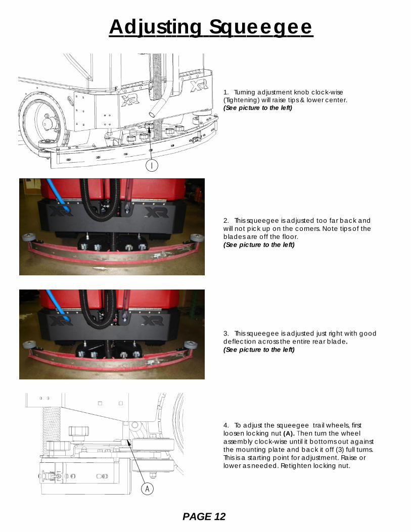
1. Turning adjustment knob clock-wise(Tightening) will raise tips & lower center.(See picture to the left)
2. This squeegee is adjusted too far back andwill not pick up on the corners. Note tips of theblades are off the floor.(See picture to the left)
3. This squeegee is adjusted just right with gooddeflection across the entire rear blade.(See picture to the left)
4. To adjust the squeegee trail wheels, firstloosen locking nut (A). Then turn the wheelassembly clock-wise until it bottoms out againstthe mounting plate and back it off (3) full turns.This is a starting point for adjustment. Raise orlower as needed. Retighten locking nut.
Adjusting Squeegee
1
A
PAGE 13
Leveling Scrubdecks
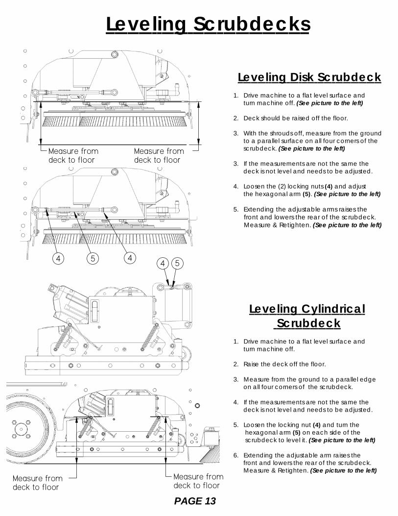
Leveling Disk Scrubdeck1. Drive machine to a flat level surface and turn machine off. (See picture to the left)
2. Deck should be raised off the floor.
3. With the shrouds off, measure from the ground to a parallel surface on all four corners of the scrubdeck. (See picture to the left)
3. If the measurements are not the same the deck is not level and needs to be adjusted.
4. Loosen the (2) locking nuts (4) and adjust the hexagonal arm (5). (See picture to the left)
5. Extending the adjustable arms raises the front and lowers the rear of the scrubdeck. Measure & Retighten. (See picture to the left)
Leveling Cylindrical Scrubdeck
1. Drive machine to a flat level surface and turn machine off.
2. Raise the deck off the floor.
3. Measure from the ground to a parallel edge on all four corners of the scrubdeck.
4. If the measurements are not the same the deck is not level and needs to be adjusted.
5. Loosen the locking nut (4) and turn the hexagonal arm (5) on each side of the scrubdeck to level it. (See picture to the left)
6. Extending the adjustable arm raises the front and lowers the rear of the scrubdeck. Measure & Retighten. (See picture to the left)
Measure from deck to floor
Measure fromdeck to floor
454 4 5
Measure fromdeck to floor
Measure fromdeck to floor

PAGE 14***FOR CORRECT PAD APPLICATION , CALL YOUR LOCAL DEALER***
1. Turn "on" machine power.
2. Raise the scrub deck by depressing the brush switch (A) to the ("0") position and turn machine power "off". Disconnect batteries.
(See picture to the left)
3. Loosen knobs (B) and remove shrouds to access scrub deck (See picture to the left)
4. Attach pads to pad drivers before connecting pad drivers to motor hub. (See picture to the left)
5. Attach brushes or pads to motor hubs. squeeze the scissor locking device (C) and lift brush up on to the motor drive hub. Make sure the scissors close and lock once the brushes are on. (See picture to the left)
6. When brushes are attached put shrouds back on machine and tighten knobs.
Attaching Disk Brushes/Pads
A
BB
C

PAGE 15
1. The shroud must be adjusted correctly in order to have proper water control during turns. the front of the shroud should be slightly higher than the rear. (See picture to the left)
2. To adjust shrouds loosen knobs (A) and remove shroud. (See picture to the left)
3. Spin the RED shroud support (B) up or down to get adjustments. (See picture to the left)
4. Once adjusted to the proper height put the shrouds back on top of adjustment supports and tighten knobs back down. (See picture to the left)
Adjusting Shrouds
A
BB
Adjusting Cylindrical Side Wipers
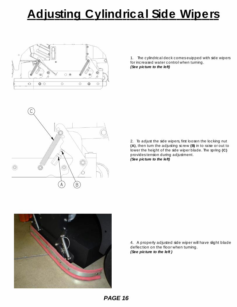
1. The cylindrical deck comes euipped with side wipersfor increased water control when turning.(See picture to the left)
2. To adjust the side wipers, first loosen the locking nut(A), then turn the adjusting screw (B) in to raise or out tolower the height of the side wiper blade. The spring (C)provides tension during adjustment.(See picture to the left)
4. A properly adjusted side wiper will have slight bladedeflection on the floor when turning.(See picture to the left )
PAGE 16
A B
C

Solution System
1. To access the items listed below, completely drain solution and recovery tanks (See picture to the left)
I. Carefully tip the tank back until it is supported by the strap.II. Gate ValveIII. Stainless steel inline filterIV. Solution Flow Valve
2. To clean filter (A) close gate valve (B).(See pictures to the left & below)
3. Unscrew clear lid (C), remove stainless steel screen (D), rinse screen.
(See pictures above & to the left)
4. Reinstall stainless filter screen & tighten cap.
5. Open gate valve (E)(See pictures to the left & below)
Closed Position
Open Position
C
D
PAGE 17
DONT LAYUNDER TANK!
BOTH TANKS EMPTY !
STRAP
AB
CDE
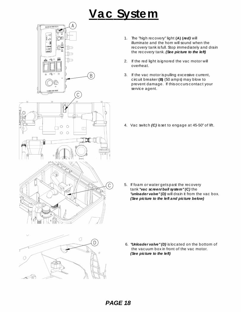
1. The "high recovery" light (A) (red) will illuminate and the horn will sound when the recovery tank is full. Stop immediately and drain the recovery tank. (See picture to the left)
2. If the red light is ignored the vac motor will overheat.
3. If the vac motor is pulling excessive current, circuit breaker (B) (50 amps) may blow to prevent damage. If this occurs contact your service agent.
4. Vac switch (C) is set to engage at 45-50" of lift.
5. If foam or water gets past the recoverytank "vac screen/ball system" (C) the"unloader valve" (D) will drain it from the vac box.(See picture to the left and picture below)
6. "Unloader valve" (D) is located on the bottom of the vacuum box in front of the vac motor. (See picture to the left)
Vac System
PAGE 18
A
B
C
C
D

One pass scrubbingSteps: (see picture below)
1. Turn machine on with the key switch.
2. Lower squeegee by pressing the switch.
3. Lower scrub head to the floor, use the top half of the brush switch.
4. Adjust the solution +/- to the desired setting. (start at half way).
5. Begin scrubbing by depressing the foot pedal slowly and then to the speed required. (Not shown)
6. Start scrubbing at the #1 or # 2 marks, do not use the #4 or #5 marks without management's approval.
7. To operate machine in reverse, simply switch the reverse switch to the reverse position, back up alarm may sound and your reverse speed is set to roughly 70% of forward.
8. To stop the machine, let off of the foot pedal and the machine will stop automatically. (Not shown)
9. Depressing the "uni-touch" button activates the solution, vacuum, and brushes simultaneously.
OperationPre-cleaning check listRead and understand the safety section onpage 5 and 6 before operating machine.
1. Check battery condition gauge on the Central Command II LCD screen. Make sure batteries are fully charged before using.
2. Check the condition of pads or brushes.
3. Check the condition of the squeegee blades.
4. Transport the machine to the filling station. Raise the scrub head and squeegee when transporting.
5. Turn machine off.
6. Open solution fill door on the top of the tank and fill the tank up with clean water or "approved" detergent. For help call Powercat Solutions at 414-745-9337. Foam in the recovery tank is usually an indication of excessive soap.
(See picture below.)
7. Add cleaning chemical. Use the proper dilution ratio indicated on the bottle.
Note: Use only nonflammable commercial cleaning chemicals.
PAGE 19
Solution Fill Port
Solution Fill"Sight Tube"
1
2 3
6
7
4
9

Double ScrubbingSteps: (see picture below)
1. Turn machine on with the key switch.
2. Lower scrub head to the floor, use the top half of the brush switch.
3. Adjust the solution to the desired setting. (set half way)
4. Begin scrubbing by depressing the foot pedal slowly and then to the speed required. (Not shown)
5. Start scrubbing at the #1 or # 2 marks, do not use the #4 or #5 marks without management's approval.
6. To operate machine in reverse, simply switch the reverse switch to the reverse position, back up alarm may sound and your reverse speed is set to roughly 70% of forward.
7. To stop the machine, let off of the foot pedal, and the machine will stop automatically. (Not shown)
Vac Only ScrubbingSteps: (see picture below)
1. Turn machine on with the key switch.
2. Lower squeegee by pressing the switch.
3. Begin vacuuming by depressing the foot pedal slowly and then to the speed required. (Not shown)
4. To operate machine in reverse, simply switch the reverse switch to the reverse position, back up alarm may sound and your reverse speed is set to roughly 70% of forward.
5. To stop the machine, let off of the foot pedal, and the machine will stop automatically. (Not shown)
Operation
PAGE 20
1
2
3
5
6
1
2
4

1. Observe the amount of solution the machine isdispensing on the floor and adjust to the desired flow.To increase the solution flow rate, push solution switch(A) +, to decrease push solution switch (A) -.(See picture to the left)
2. Keep an eye on the "red" recovery full light (B) tomake sure there is not foamy buildup in the recoverytank. If excess foam begins to develop, pour arecommended foam control solution into therecovery tank.(See picture to the left)
3. Always operate at lower speeds when scrubbingaround walls and objects. You should reduce thespeed, to maintain control when turning.
4. If squeegee starts to streak, raise and wipe theblades with a clean cloth. If the problem continues,check the blades for wear or damage, and rotate ifneeded.
5. Change or turn over pads when dirty. Rotate thescrub brushes every week.
6. Stay clear of objects protruding from the floor,such as sockets, grates, for they will damage thepads and squeegee blades.
7. During brief stops you should turn everything off,the brushes and solution will automatically stop whenthe foot pedal is released.
8. Always keep an eye on your gauges. They let youknow the status of a particular system at a glance. Ifyour battery gauge is reading low, you must stopimmediately, and recharge. Running the batteriesdead, will result in damage to the batteries.
9. When you run out of solution, raise the brushes,and continue to vacuum the remaining water until itis consumed. The "yellow" low solution light (C) willlight up when the solution is low and the sight tubeon the back of the tank tells you how much solutionis left in the tank, (See picture to the left)
10. When you are ready to stop, pick up the brushes,turn off the solution switch, pick up the squeegee,and drive the machine back to the charging area.
Operating Hints
Sight Tube
PAGE 21
A
B
C

2. Remove cap and begin draining, squeeze "C"to control flow. (See picture below)
3. Open the top "recovery tank lid" and flush out withfresh water to keep tank clean. Rinse the recovery tankafter every use. This will prevent heavy build up on thebottom of the tank, foul odors and clogging of the drainhose. Empty "Drain Saver".
Always empty recovery tank when refilling the solutiontank. To drain the recovery tank, perform the followingsteps.
1. Remove drain hose "B" and unscrew cap. Open thetop "recovery access lid" and flush out with fresh waterto keep tank clean. (See picture below)
4. Once tank is empty, put the cap back on and placehose back on hook.
Drain Solution TankTo drain left over cleaning solution from the solution tank,perform the following steps.
1. Pull the clear sight tube/drain hose (A) off barbed fitting. (See picture below)
2. Rinse out tank and solution flow system with clean water.
C
* It is the customers responsibility to verify that discardedwater is in compliance with local, state, and federallaws. DO NOT DRAIN INTO "STORM DRAINS" !
Drain Recovery Tank
Overide Parking BrakeThe parking brake must be released "prior" to attempting to"push/pull" the machine manually. Perform the followingsteps in any order.
1. Disconnect both positive and negative leads (1 & 2) fromthe traction motor. (See picture below)
2. Turn wingnut (3) clockwise to release the parking brake. (See picture below)
PAGE 22
A B
1
2
3
Recovery TankDrain Saver
Recovery TankFloat Shut-Off
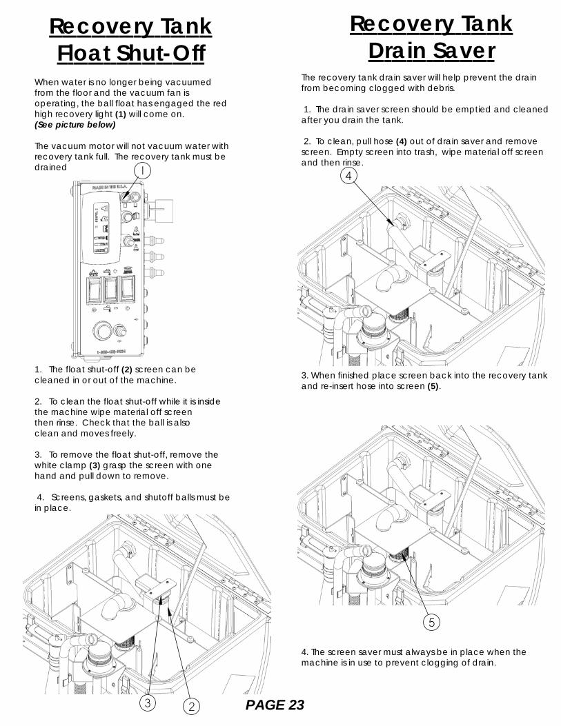
When water is no longer being vacuumedfrom the floor and the vacuum fan isoperating, the ball float has engaged the redhigh recovery light (1) will come on.(See picture below)
The vacuum motor will not vacuum water withrecovery tank full. The recovery tank must bedrained
1. The float shut-off (2) screen can becleaned in or out of the machine.
2. To clean the float shut-off while it is insidethe machine wipe material off screenthen rinse. Check that the ball is alsoclean and moves freely.
3. To remove the float shut-off, remove thewhite clamp (3) grasp the screen with onehand and pull down to remove.
4. Screens, gaskets, and shutoff balls must bein place.
The recovery tank drain saver will help prevent the drainfrom becoming clogged with debris.
1. The drain saver screen should be emptied and cleanedafter you drain the tank.
2. To clean, pull hose (4) out of drain saver and removescreen. Empty screen into trash, wipe material off screenand then rinse.
3. When finished place screen back into the recovery tankand re-insert hose into screen (5).
4. The screen saver must always be in place when themachine is in use to prevent clogging of drain.
PAGE 23
1 4
5
23

Standard ChargerCaution: the following instructions are intended for the36v charger supplied with the machine. Do not useany non OEM charger with this machine.
1. Transport machine to a well ventilated area forcharging.
2. Turn the machine off.
3. Hinge opens the tank to expose the batteries.(See picture to the left)
Caution: (always wear eye protection when batteriesare exposed)
4. Check the water level in each battery. Do notcharge the machine unless the water is slightly higherthan the plates. If needed, add enough distilledwater to 1/2” above the plates. Do not over fill.Batteries can overflow during charging. Replacecaps before charging.
5. With the grey (175) charger plug disconnectedfrom the machine, plug the charger power cord intoa grounded 110 volt standard wall outlet.
6. Connect the grey charger plug into the batterycharging port (A) located on the seat pedestal.
7. The charger will automatically begin charging,and automatically shut off when fully charged(Check gauge)
8. After the charger has turned off, unplug the greycharger plug from the machine and disconnect thecharger from the wall outlet.
9. Recheck the cell level after charging. If needed,add distilled water up to the correct level. Be certainto replace the caps securely and to wipe off the topof the batteries.
Standard Battery ChargingCharger SpecificationsOutput voltage of 36 volts. (Standard)Output current of 36 amps max. (Standard)Input voltage of 110 volts/60 Hz. (standard)Automatic shut off circuit.Made for deep cycle batteries.
Danger: always charge batteries in a well ventilated area.Batteries emit hydrogen gas. Explosion or fire can result.Keep sparks and flame away. Shield eyes when servicingbatteries and avoid contact with battery acid.Leave access panel open when charging!
PAGE 24
A

PAGE 25
Optional Battery Charging
Description of LEDRed LED Battery level low.
Yellow Led Battery at 1/2 charge.
Green LED battery fully charged.
Charger SpecificationsOutput voltage of 36 volts. (optional)Output current of 30 amps max.Input voltage of 110 volts/60 Hz.Automatic shut off circuit.Made for deep cycle batteries, wet or sealed.
Danger: always charge batteries in a well ventilated area.Batteries emit hydrogen gas. Explosion or fire can result.Keep sparks and flame away. Shield eyes when servicingbatteries and avoid contact with battery acid.Leave access panel open when charging!
Close-up of charger LCD
On-Board ChargerCaution: the following instructions are intended for the 36v"optional" on-board charger (A). (See left middle picture)
1. Transport machine to a well ventilated area forcharging.
2. Turn the machine off.
3. Hinge open the tank to expose the batteries. (See figure50.) Caution: (always wear eye protection when batteriesare exposed)
4. Check the water level in each battery. Do not chargethe machine unless the water is slightly higher than theplates. If needed, add enough distilled water to 1/2” abovethe plates. Do not over fill. Batteries can overflow duringcharging. Replace caps before charging.
5. Plug the extension cord into a grounded 110 volt/60 Hzstandard wall outlet & flip switch. (See picture to the left)* NOTE: MUST HAVE 20 AMP SERVICE.
6. The charger will automatically begin charging, andautomatically shut off when fully charged(Check gauge)
7. After the charger has turned off, unplug the extensioncord from the machine and disconnect from the walloutlet. (See picture to the left)
8. Recheck the cell level after charging. If needed, adddistilled water up to the correct level. Be certain to replacethe caps securely and to wipe off the top of the batteries.
A

On-Board Charger Operator Manual
PAGE 26
Charge Status LED's
LCD DisplayMain PowerSwitch

On-Board Charger Operator Manual
PAGE 27

On-Board Charger Operator Manual
PAGE 28
-
-
-
--
-
+
+
+
+
+
+
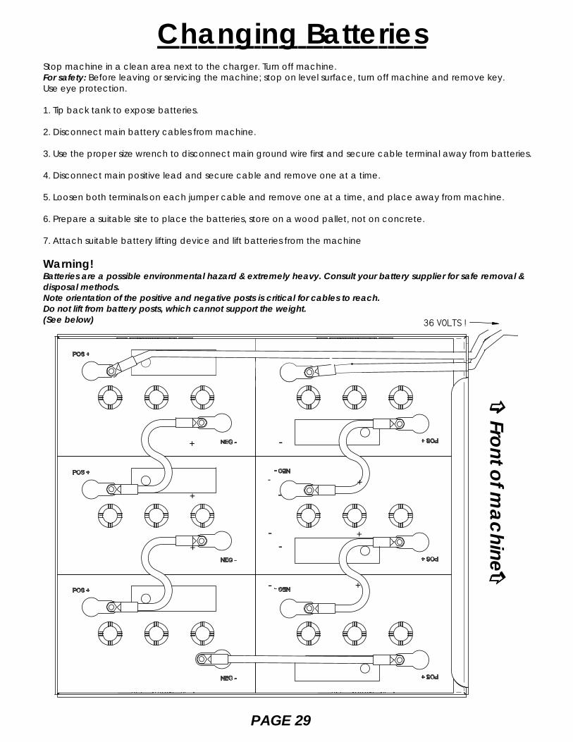
36 VOLTS !
Front of machine
Changing BatteriesStop machine in a clean area next to the charger. Turn off machine.For safety: Before leaving or servicing the machine; stop on level surface, turn off machine and remove key.Use eye protection.
1. Tip back tank to expose batteries.
2. Disconnect main battery cables from machine.
3. Use the proper size wrench to disconnect main ground wire first and secure cable terminal away from batteries.
4. Disconnect main positive lead and secure cable and remove one at a time.
5. Loosen both terminals on each jumper cable and remove one at a time, and place away from machine.
6. Prepare a suitable site to place the batteries, store on a wood pallet, not on concrete.
7. Attach suitable battery lifting device and lift batteries from the machine
Warning!Batteries are a possible environmental hazard & extremely heavy. Consult your battery supplier for safe removal &disposal methods.Note orientation of the positive and negative posts is critical for cables to reach.Do not lift from battery posts, which cannot support the weight.(See below)
PAGE 29

Side Broom System1. Flip side broom switch (A) up to lower and engage broom. (See picture below)
2. To adjust side broom height, loosen locking nut located behind screwhead (B) of screw that is in front of scrubdeck just inside the side wall of frame on each side of the machine. Use 1/2" wrench to loosen locking nut. (See picture below)
3. Turn adjustment screw (B) counter-clockwise(loosens) to lower side brooms. Turn screw
clock-wise (tightens) to raise side brooms.
4. Retighten locking nut.
7. Picture below shows brooms to low.
5. Side broom adjustment slot (C).(See picture below)
8. Picture below shows brooms just right.
6. Picture below shows brooms to high.
A
B
C
PAGE 30

Overhead Guard1. Your machine may be equipped with an"optional""Overhead Guard" (A) that helps protect the operatorfrom falling objects that are above the operators head.(See picture below)
Pre-treat Soap1. Your machine is may be with "optional" "Pre-treatSoap" (B).2. It helps remove stains that a normal detergent cannot get out of floor. (See picture below)
Non-marking tires1. Your machine may be equipped with non marking(D) tires, which may have reduced traction on somefloors (See picture above)
Industrial Battery1. Your machine may be equipped with "optional""Heavy Duty Industrial Battery" and charger thatprovides longer machine run time.(See picture below)
PAGE 31
HD Side Doors1. Your machine may be equipped with "optional""Heavy Duty Side Doors" (C) that helps protect themachine's scrubdeck from collision damage.(See picture below)
On-board charger1. Your machine may be equipped with "optional""On-board charger (E) that will charge your machine.(See picture to the left)
Machine options
A
B
E
C
D
PAGE 32
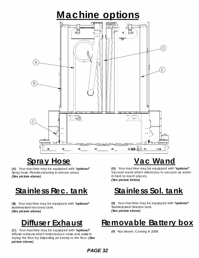
Spray Hose(A) Your machine may be equipped with "optional"Spray hose. Permits cleaning in remote areas.(See picture above)
Vac Wand(D) Your machine may be equipped with "optional"Vacuum wand which allows you to vacuum up waterin hard to reach places.(See picture below)
Stainless Sol. tank(B) Your machine may be equipped with "optional"stainless steel recovery tank.(See picture above)
(E) Your machine may be equipped with "optional"Stainless steel Solution tank.(See picture above)
Diffuser Exhaust(C) Your machine may be equipped with "optional"diffuser exhaust which helps reduce noise and assist indrying the floor by dispersing air evenly to the floor. (Seepicture above)
Removable Battery box(F) Not shown. Coming in 2008
Stainless Rec. tank
Machine options
A
D
E
B
C

On-board Soap1. Switch toggel switch up once fornormal soap distribution and up twicefor heavy duty soap distribution.(See picture at top of the page item "A").
Vac Wand1. Turn on spray jet pump using thetogle switch on the centralcommand.(See picture at top of page item "B" )2. Detach srap hose from back ofmachine and squieeze handel.(See picture above)
Spray Hose
Machine options
1. Detach vac hose from squeegeeand attach it to the vac wand.(See picture above)2. Turn on vac motors using the togleswitch on the central command.(See picture at top of page item "C" )Heavy duty soap
No soap
Normal soap
PAGE 33
B C
AAttach vac hose here

Yearly Maintenance 1. Call your local dealer for yearly maintenance
Storing Machine1. Be sure to flush the tanks out completely. To thoroughlyflush out any solution chemicals in solution line andvalves, refill solution tank with a few gallons of warm cleanwater and run machine until tank is empty.
2. Open the recovery tank lid to promote air circulation.
3. Raise brushes and squeegee.
Checking Battery Specific GravityUse a hydrometer to check the battery specific gravity.
Checking GravityA. HydrometerB. BatteryNote: do not take readings immediately after addingdistilled water, if water and acid are not thoroughly mixed,the reading may not be accurate.
Check the hydrometer against this chart
Daily Maintenance1. Remove and clean pads or brushes. Never use soiledpads when cleaning. Replace pads when they becomepacked with residue.
2. Remove and clean debris from the float shut-off screenand drain saver located inside the recovery tank.
3. Drain and rinse tanks thoroughly.
4. Inspect vacuum hose for any objects obstructing theair flow.
5. Raise squeegee and wiper blades with a clean cloth.Store squeegee in the raised position to prevent damageor setting of the blades.
6. Wipe down machine if needed. Use a nonabrasive,non solvent cleaner, or a clean damp cloth.
7. Recharge the batteries if needed.
Weekly Maintenance 1. Check battery water level in each cell of the batteries,and fill as needed. Always usedistilled water to refillbatteries. Batteries should be filled approximately 3/4" to 1"above the plates. Overfilling will cause the batteries toleak during charging. The charging process creates gasbubbles inside the battery, which effectively increases thevolume of the electrolyte.
2. Clean battery tops to prevent corrosion.
3. Rotate brushes. Rotate the left to the right and right toleft. On cylindrical models from front to back, or end toend if using different materials.
4. Drain and rinse tanks thoroughly. To thoroughly flushout any solution chemicals in solution line and valves,refill solution tank with a few gallons of warm clean waterand run machine until tank is empty.
Monthly Maintenance 1. Check scrub head and squeegee lifting cables forwear and spring tension.
2. Check machine for water leaks and loose nuts andbolts.
3. Check to see if battery cables are tightened(Tighten if needed)
4. Check parking brake
Maintenance
SPECIFIC GRAVITY@ 80v F (27vC) BATTERY CONDITION
1.2651.2251.1901.1551.120
100% CHARGED75% CHARGED50% CHARGED25% CHARGEDDISCHARGED
Note: if the readings are taken when thebattery electrolyte is any temperatureother than 80vF (27vC), the readingmust be temperature corrected.
To find the corrected specific gravity readingwhen the temperature of the battery electrolyteis other than 80vF (27vC): add (+) to the specificgravity reading 0.004 (4 points), for each 10vF(6vC) above 80v (27vC).subtract (-) from the specific reading 0.004(4 points), for each 10vF (6vC) below 80vF (27vC).
PAGE 34

PAGE 35
Maintenance Sevice ScheduleMaintenance Before each work
periodAfter each workperiod
50 hrs 100 hrs 200 hrs
Check water level of batteries after chargingadd distilled water if necessary
X
Check that recovery tank cover seals tightly XVisualy check for damaged or worn tires XCheck brushes or pads for proper installation XCheck vacuum hose connections XCheck that squeegee is securely attachedand properly adjusted
X
Check that side squeegees are properlyadjusted
x
Check for attached drain hose, plug andcaps
X
Check parking brake and steering for properoperation
X
Inspect vacuum filter for debris XClean out solution tank and filter, check flow XRun vacuum motors to dry XClean brushes or pads and check for wear XClean main and side squeegee blades andcheck for wear
X
Clean out recovery tank and vacuum filter XClean and inspect flow shutoff XClean outside of tanks and check fordamages
X
Store with tank covers open XCharge batteries XCheck side squeegee for wear XClean off top of batteries XCheck battery cells with hydrometer XInspect scrub deck skirt XClean solution strainer XCheck battery connections are tight XCheck parking brake adjustment XCheck battery case and batterycompartment
X
Check brake for damage or wear XClean pivot points on squeegee and scrubdeck
X
Check all motors for carbon brush wear XCheck motor commutators XCheck steering chain tensioner X
NOTE: Traction drive, wheels and batteries should be serviced based on traction drivehour meter. The scrub brush hour meter should be used for all other service schedule items.
Maintenance Service Schedule

Preventative Maintenance Records
PAGE 36
CUSTOMER INFORMATION
CUSTOMERADDRESSCITY STATE ZIP CODE
MACHINE INFORMATION
MODEL # SERIAL #WORK ORDER# HOUR METER:
BATTERY CONDITION Cell #1 Cell #2 Cell #3Battery # 1 Hydrometer Reading Battery # 1 Water Condition Battery # 2 Hydrometer Reading Battery # 2 Water condition Battery # 3 Hydrometer Reading Battery # 3 Water Condition Battery # 4 Hydrometer Reading Battery # 4 Water condition Battery # 5 Hydrometer Reading Battery # 5 Water Condition Battery # 6 Hydrometer Reading Battery # 6 Water Condition
Clean Battery Tops. Check Battery Cable and Terminal ConditionNOTES:
BRUSH CONDITIONScrub Brush Fiber Length Rotated BrushesBrush Drive Sockets Good Worn Needs ReplacementDrive Hubs Good Worn Needs ReplacementSide Broom Condition Good Worn Needs Replacement Rotated Side to Side
CHECK OPERATION AND CONDITION OF: IN SPEC REPAIR PROBLEMSteering wheel Tilt MechanismKey SwitchHornHead LightLCD DisplayPage ButtonBrush Pressure ButtonBrush Pressure Managers Lock OutFoot PedalReverse SwitchBack Up AlarmOne Touch Switch
Preventative Maintenance Records
PAGE 37
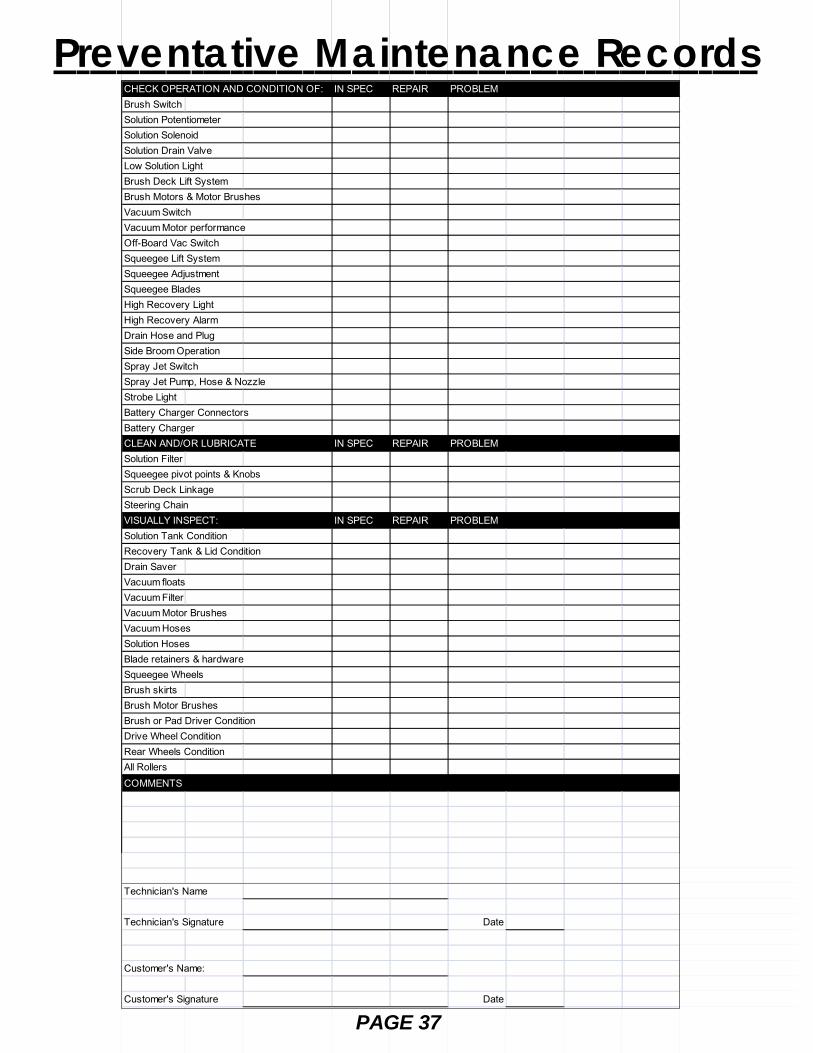
CHECK OPERATION AND CONDITION OF: IN SPEC REPAIR PROBLEMBrush SwitchSolution PotentiometerSolution SolenoidSolution Drain ValveLow Solution LightBrush Deck Lift SystemBrush Motors & Motor BrushesVacuum SwitchVacuum Motor performanceOff-Board Vac SwitchSqueegee Lift SystemSqueegee AdjustmentSqueegee BladesHigh Recovery LightHigh Recovery AlarmDrain Hose and PlugSide Broom OperationSpray Jet SwitchSpray Jet Pump, Hose & NozzleStrobe LightBattery Charger ConnectorsBattery ChargerCLEAN AND/OR LUBRICATE IN SPEC REPAIR PROBLEMSolution FilterSqueegee pivot points & KnobsScrub Deck LinkageSteering ChainVISUALLY INSPECT: IN SPEC REPAIR PROBLEMSolution Tank ConditionRecovery Tank & Lid ConditionDrain SaverVacuum floatsVacuum FilterVacuum Motor BrushesVacuum HosesSolution HosesBlade retainers & hardwareSqueegee WheelsBrush skirtsBrush Motor BrushesBrush or Pad Driver ConditionDrive Wheel ConditionRear Wheels ConditionAll RollersCOMMENTS
Technician's Name
Technician's Signature Date
Customer's Name:
Customer's Signature Date

Troubleshooting Central CommandNote: this machine is operated by a sophisticated electronic "controller" that has many fail-safes within it. Itself-analyzes problems and flashes a four-digit alpha-numeric code of what is wrong in the LCD window.
Most of these codes require a technician attention. You should not attempt repairs you are unfamiliar with, especially ifyou are not authorized to work on this equipment.
The complete list of codes is published in the simplified electronic troubleshooting manual, which is available toauthorized and certified distribution technicians. However, we have included the basic codes that you can usuallyresolve yourself.
1. 7601 and 7602 Error. Scrub deck current over load.This can occur when driving over a bump in the floor. Torestart, turn off the key and turn it on again. To avoid thiserror, either slow down on bumpy parts of the floor, orreduce down pressure on the pads.
2. 1500 Error. There is an open in the parking brakecircuit. Check the parking brake wiring and the parkingbrake coil to find the open circuit.
3. 7700, 7701, 7702, and 7703 Error. The vacuum motorhas exceeded their authorized power limits. Turn off keyand turn on again to clear.
4. BOOST ON Allows front wheel drive to draw morepower when needed to climb ramps for 30 seconds.
PAGE 38

9. All other error codes. Turn off the key, and disconnect the positive battery cable from the batteries for more thanone minute (the time is needed to drain the controler on-board capacitor). Reconnect cables, being sure that it istight. Too loose and you will burn battery. If you over tighten the cables you can damage the battery lead terminal.Try again.
10. If the problems cannot be solved by any of this solution, call your local dealer service department.
5. 7700. Vacuum motor circuit is open.
6. Throttle error. You pressed the foot pedal beforeturning on the key. Turn off the key and try again, leavingfoot off of the pedal.
7. 2C00 and 2C01 error. Low voltage warning. Voltagehas dropped down below the minimum required tooperate the machine. If you wait a few minutes, thebatteries may come up in voltage, allowing you to drivevery slowly to the recharge station. If not, you will have torelease the parking brake (on the front wheel, pull levertoward the front of the machine to release) and push themachine to recharging station. You must disconnect thetraction motor! (+ cable first)
8. 7802 error. The traction motor pulled excessive currentperhaps running a ramp for more than the 60 secondsallowing for this. Turn off the key, turn on again, andcontinue. You should not use this machine to climb rampsso steep and so long that this code comes up repeatedly,or you could overheat the traction motor.
Troubleshooting Central Command
PAGE 39

Problem
No power, nothing operates
Brush motor(s) do not operate
Drive motor does not operate
Vacuum motor does not operate
Drive motor runs incorrectly
Insufficient solution flow
Cause
Faulty key switchBatteries need chargingFaulty batteryLoose battery cableMain circuit breaker tripped
Brush deck is not downFoot pedal is not depressedBrush circuit breaker tripped
Carbon brushes wornFaulty brush motor or wires
Recharge switch misadjustedFaulty speed controller or wiresFaulty drive motorFaulty wiringCarbon brushes worn
Squeegee is in the up positionFaulty vacuum switchVacuum circuit breaker tripped
Faulty vacuum motor
Faulty speed controller or wiresFaulty potentiometerLoose wires
Solution tank low
Flow knob turned downSolution filter cloggedSolution line clogged
Solution valve clogged
Solution
Contact local servicing dealerSee charging batteriesReplace batteryTighten loose cableWait 5 minutes for auto resetDetermine cause and correct
Put brush deck downEngage foot pedalWait 5 minutes for auto resetDetermine cause and correctContact local servicing dealerContact local servicing dealer
Contact local servicing dealerContact local servicing dealerContact local servicing dealerContact local servicing dealerContact local servicing dealer
Rotate squeegee lift lever downTry operating "white” toggleWait 5 minutes for auto resetDetermine cause and correctContact local servicing dealer
Contact local servicing dealerContact local servicing dealerContact local servicing dealer
Refill solution tank, drain recoverytankMove lever to onRemove cover and cleanRemove and blow out withcompressed airRemove cover and clean
Troubleshooting
PAGE 40

Problem
No solution flow
Poor water recovery
Poor water recovery on turns
Rear tires noisy
Poor traction
Short run time
Cause
No solution in tankSolution valve offSolution switch offSolution screen cloggedFaulty solution solenoidFaulty solution switch
Recovery tank is fullBall/screen in recoveryTank is cloggedVacuum hose is cloggedSqueegee is cloggedSqueegee blade is wornFaulty vacuum hoseVacuum motor gasket tornTank gasket faultyDrain plug looseVac motor faultyBattery charge low
Wipers wornWipers chatterSqueegee swing is bindingIncorrect squeegee size
Bearing dryFaulty hubs
Excessive brush pressureWorn drive tireHeavy soap concentration
Batteries run downBatteries still downBatteries low on water
Batteries over cycled
Solution
Fill solution tankRotate lever to onTurn solution switch onRemove and clean screenContact local servicing dealerContact local servicing dealer
Empty recovery tankRemove screen and clean
Remove debrisRemove debrisRotate or replace bladesContact local servicing dealerContact local servicing dealerContact local servicing dealerTighten lidContact local servicing dealerCharge batteries overnight
Replace wiper materialTighten pivot pointsContact local servicing dealerContact local servicing dealer
Grease bearingsContact local servicing dealer
Reduce pressure with switch
Contact local servicing dealer
Charge batteries twiceContact local servicing dealerFill with distilled water to 3/4"above the lead platesContact local servicing dealer
Troubleshooting
PAGE 41