Xm Operation Manual-J - SteppIR Antennas · SE P P TT E P P I R ™ A N T E N N A S — O P E R A T...
40
OPERATORS MANUAL C3 C4 C5 C6 C11 C15 C16 C22 C23 C24 C25 C26 C27 C28 C31 2 C34 C35 C36 D5 IC1 J1 J2 13 25 2,54 1 3 5 7 9 1 J8 L1 Q1 R3 R5 R6 R7 R12 R18 R19 R20 R21 R22 R24 R29 R30 R32 R36 R37 R38 R39 R42 R43 R47 U3 U4 U5 R33 Revision 5/12/08 SteppIR Antennas 2112-116th Ave NE, Suite 2-5, Bellevue, WA 98004 Tel: 425-453-1910 Fax: 425-462-4415 Tech Support: 425-891-6134 www.steppir.com
Transcript of Xm Operation Manual-J - SteppIR Antennas · SE P P TT E P P I R ™ A N T E N N A S — O P E R A T...

OPERATORS MANUAL C
3C
4C
5C
6
C1
1
C1
5C
16
C2
2C
23
C2
4C
25
C2
6
C2
7C
28
C3
1
C3
2C
34
C3
5
C3
6
D5
IC1
J1J2
13 25
2,54
1
3
5
7
9
1J8
L1
Q1
R3
R5
R6
R7
R1
2R1
8R
19
R2
0R
21
R2
2R
24
R2
9R
30
R3
2R
36
R3
7R
38
R3
9R
42
R4
3
R4
7
U3
U4
U5
R3
3
Revision 5/12/08
SteppIR Antennas 2112-116th Ave NE, Suite 2-5, Bellevue, WA 98004
Tel: 425-453-1910 Fax: 425-462-4415 Tech Support: 425-891-6134
www.steppir.com

Topics Page Table of Contents 2
Connecting the Antenna to the Controller 3
Antenna Controllers 4
Using the Antenna Controller 5
Modes of Operation 6
Amateur Mode 6
General Frequency Mode 7
Setup Mode 8
Test Motor 9
Restoring the Factory Default Antenna Segments 10
Transceiver Interface (Optional) 11
Saving Settings (Transceiver Interface) 12
Using the Controller with a Logging Program 12
Creating and Modifying Antennas 13
Calibrating Antenna 16
Retracting the Elements 16
Normal, 180 degree and bi-directional Function 17
Saving Antennas to Memory 17
Appendix B - Yagi Troubleshooting Guide 21
SteppIR Warranty 39
Appendix C - Vertical Troubleshooting Guide 27
SteppIR Notes 38
Appendix A - SteppIR Performance 19
Appendix D - Transceiver Interface Installation 30
Appendix E - Firmware Chip Replacement Procedures 34
SSST E P PT E P PT E P P I R ™ AI R ™ AI R ™ A N T E N N A SN T E N N A SN T E N N A S ——— OOO P E R A T I O NP E R A T I O NP E R A T I O N 2
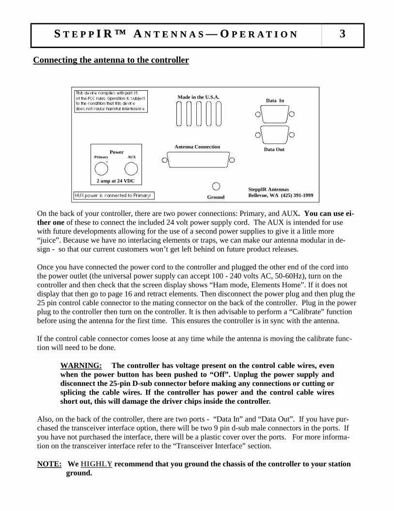
Connecting the antenna to the controller
SSST E P PT E P PT E P P I R ™ AI R ™ AI R ™ A N T E N N A SN T E N N A SN T E N N A S ——— OOO P E R A T I O NP E R A T I O NP E R A T I O N 3
On the back of your controller, there are two power connections: Primary, and AUX. You can use ei-ther one of these to connect the included 24 volt power supply cord. The AUX is intended for use with future developments allowing for the use of a second power supplies to give it a little more “juice”. Because we have no interlacing elements or traps, we can make our antenna modular in de-sign - so that our current customers won’t get left behind on future product releases. Once you have connected the power cord to the controller and plugged the other end of the cord into the power outlet (the universal power supply can accept 100 - 240 volts AC, 50-60Hz), turn on the controller and then check that the screen display shows “Ham mode, Elements Home”. If it does not display that then go to page 16 and retract elements. Then disconnect the power plug and then plug the 25 pin control cable connector to the mating connector on the back of the controller. Plug in the power plug to the controller then turn on the controller. It is then advisable to perform a “Calibrate” function before using the antenna for the first time. This ensures the controller is in sync with the antenna. If the control cable connector comes loose at any time while the antenna is moving the calibrate func-tion will need to be done.
WARNING: The controller has voltage present on the control cable wires, even when the power button has been pushed to “Off”. Unplug the power supply and disconnect the 25-pin D-sub connector before making any connections or cutting or splicing the cable wires. If the controller has power and the control cable wires short out, this will damage the driver chips inside the controller.
Also, on the back of the controller, there are two ports - “Data In” and “Data Out”. If you have pur-chased the transceiver interface option, there will be two 9 pin d-sub male connectors in the ports. If you have not purchased the interface, there will be a plastic cover over the ports. For more informa-tion on the transceiver interface refer to the “Transceiver Interface” section. NOTE: We HIGHLY recommend that you ground the chassis of the controller to your station
ground.
Ground
SteppIR Antennas Bellevue, WA (425) 391-1999
Data Out
Data In
Antenna Connection
Made in the U.S.A.
Power Primary AUX
2 amp at 24 VDC
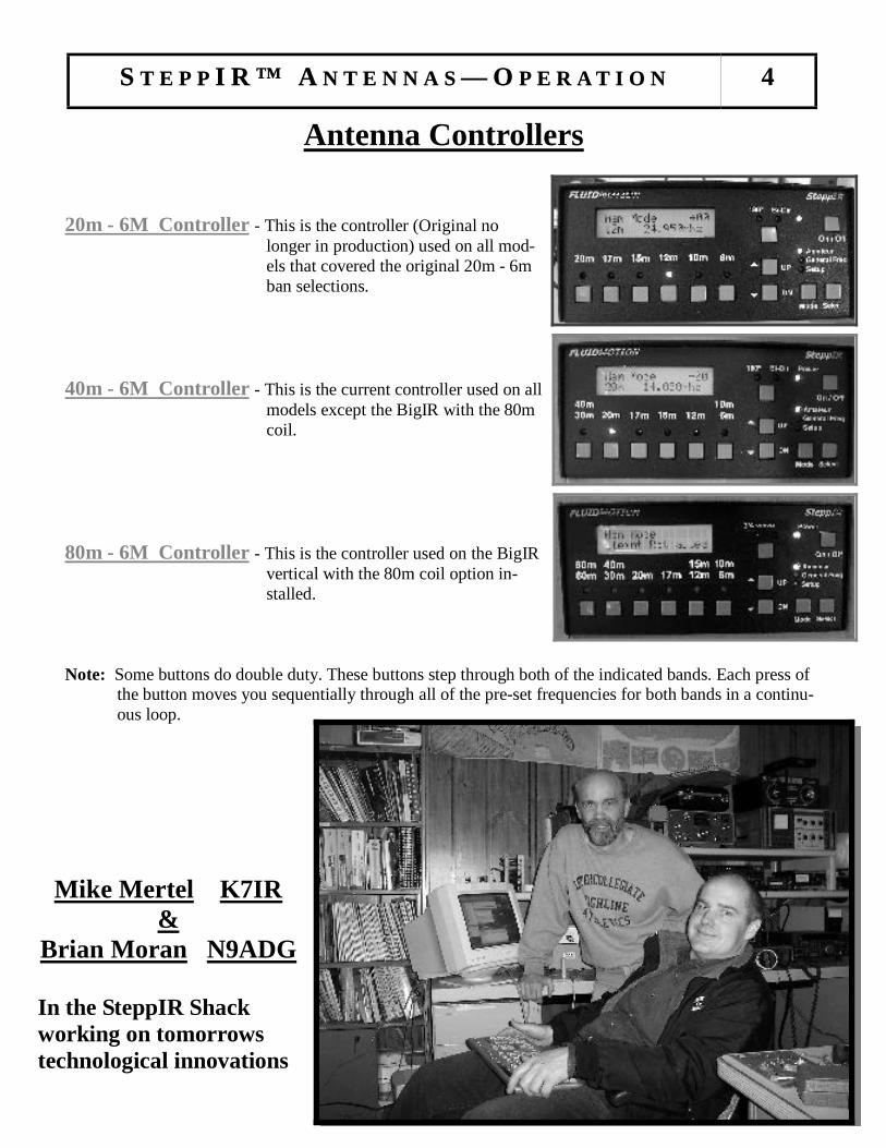
Antenna Controllers 20m - 6M Controller - This is the controller (Original no
longer in production) used on all mod-els that covered the original 20m - 6m ban selections.
40m - 6M Controller - This is the current controller used on all
models except the BigIR with the 80m coil.
80m - 6M Controller - This is the controller used on the BigIR
vertical with the 80m coil option in-stalled.
Note: Some buttons do double duty. These buttons step through both of the indicated bands. Each press of
the button moves you sequentially through all of the pre-set frequencies for both bands in a continu-ous loop.
SSST E P PT E P PT E P P I R ™ AI R ™ AI R ™ A N T E N N A SN T E N N A SN T E N N A S ——— OOO P E R A T I O NP E R A T I O NP E R A T I O N 4
Mike Mertel K7IR &
Brian Moran N9ADG
In the SteppIR Shack working on tomorrows technological innovations
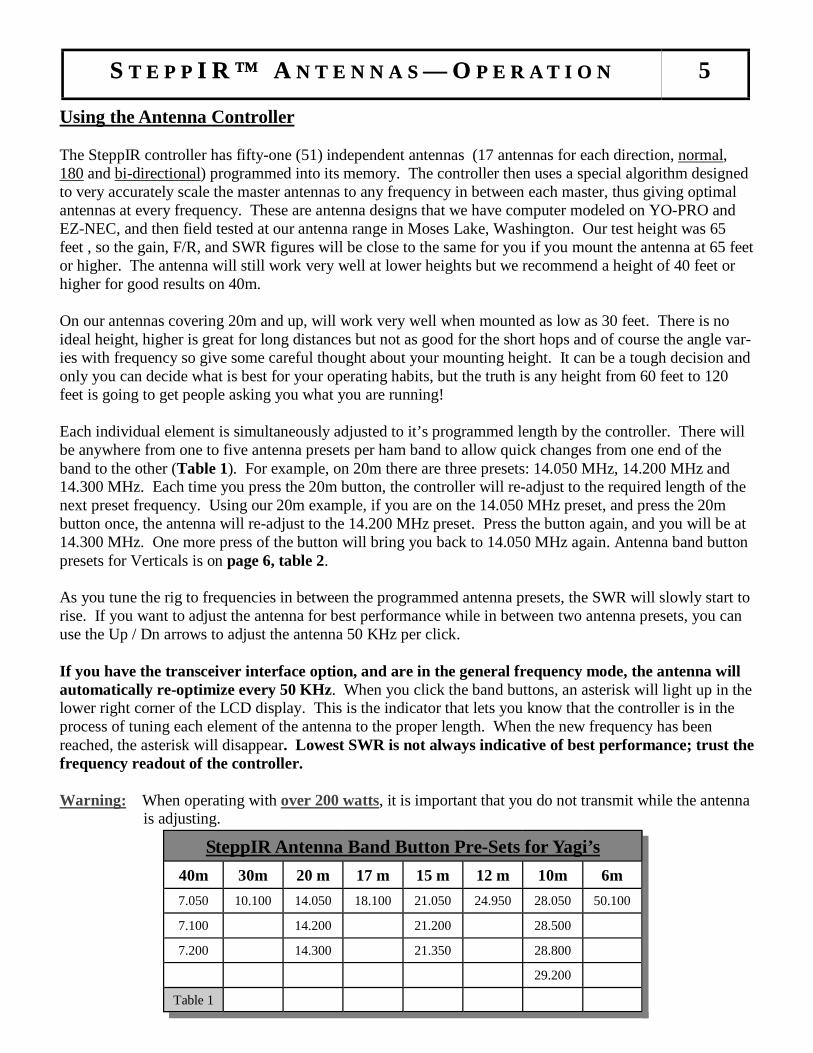
Using the Antenna Controller The SteppIR controller has fifty-one (51) independent antennas (17 antennas for each direction, normal, 180 and bi-directional) programmed into its memory. The controller then uses a special algorithm designed to very accurately scale the master antennas to any frequency in between each master, thus giving optimal antennas at every frequency. These are antenna designs that we have computer modeled on YO-PRO and EZ-NEC, and then field tested at our antenna range in Moses Lake, Washington. Our test height was 65 feet , so the gain, F/R, and SWR figures will be close to the same for you if you mount the antenna at 65 feet or higher. The antenna will still work very well at lower heights but we recommend a height of 40 feet or higher for good results on 40m. On our antennas covering 20m and up, will work very well when mounted as low as 30 feet. There is no ideal height, higher is great for long distances but not as good for the short hops and of course the angle var-ies with frequency so give some careful thought about your mounting height. It can be a tough decision and only you can decide what is best for your operating habits, but the truth is any height from 60 feet to 120 feet is going to get people asking you what you are running! Each individual element is simultaneously adjusted to it’s programmed length by the controller. There will be anywhere from one to five antenna presets per ham band to allow quick changes from one end of the band to the other (Table 1). For example, on 20m there are three presets: 14.050 MHz, 14.200 MHz and 14.300 MHz. Each time you press the 20m button, the controller will re-adjust to the required length of the next preset frequency. Using our 20m example, if you are on the 14.050 MHz preset, and press the 20m button once, the antenna will re-adjust to the 14.200 MHz preset. Press the button again, and you will be at 14.300 MHz. One more press of the button will bring you back to 14.050 MHz again. Antenna band button presets for Verticals is on page 6, table 2. As you tune the rig to frequencies in between the programmed antenna presets, the SWR will slowly start to rise. If you want to adjust the antenna for best performance while in between two antenna presets, you can use the Up / Dn arrows to adjust the antenna 50 KHz per click. If you have the transceiver interface option, and are in the general frequency mode, the antenna will automatically re-optimize every 50 KHz. When you click the band buttons, an asterisk will light up in the lower right corner of the LCD display. This is the indicator that lets you know that the controller is in the process of tuning each element of the antenna to the proper length. When the new frequency has been reached, the asterisk will disappear. Lowest SWR is not always indicative of best performance; trust the frequency readout of the controller. Warning: When operating with over 200 watts, it is important that you do not transmit while the antenna
is adjusting.
SSST E P PT E P PT E P P I R ™ AI R ™ AI R ™ A N T E N N A SN T E N N A SN T E N N A S ——— OOO P E R A T I O NP E R A T I O NP E R A T I O N 5
SteppIR Antenna Band Button Pre-Sets for Yagi’s
40m 30m 20 m 17 m 15 m 12 m 10m 6m
7.050 10.100 14.050 18.100 21.050 24.950 28.050 50.100
7.100 14.200 21.200 28.500
7.200 14.300 21.350 28.800
29.200
Table 1
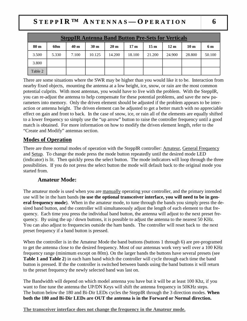
There are some situations where the SWR may be higher than you would like it to be. Interaction from nearby fixed objects, mounting the antenna at a low height, ice, snow, or rain are the most common potential culprits. With most antennas, you would have to live with the problem. With the SteppIR, you can re-adjust the antenna to help compensate for these potential problems, and save the new pa-rameters into memory. Only the driven element should be adjusted if the problem appears to be inter-action or antenna height. The driven element can be adjusted to get a better match with no appreciable effect on gain and front to back. In the case of snow, ice, or rain all of the elements are equally shifted to a lower frequency so simply use the “up arrow” button to raise the controller frequency until a good match is obtained. For more information on how to modify the driven element length, refer to the “Create and Modify” antennas section. Modes of Operation There are three normal modes of operation with the SteppIR controller: Amateur, General Frequency and Setup. To change the mode press the mode button repeatedly until the desired mode LED (indicator) is lit. Then quickly press the select button. The mode indicators will loop through the three possibilities. If you do not press the select button the mode will default back to the original mode you started from. Amateur Mode: The amateur mode is used when you are manually operating your controller, and the primary intended use will be in the ham bands (to use the optional transceiver interface, you will need to be in gen-eral frequency mode). When in the amateur mode, to tune through the bands you simply press the de-sired band button, and the controller will simultaneously adjust the length of each element to that fre-quency. Each time you press the individual band button, the antenna will adjust to the next preset fre-quency. By using the up / down buttons, it is possible to adjust the antenna to the nearest 50 KHz. You can also adjust to frequencies outside the ham bands. The controller will reset back to the next preset frequency if a band button is pressed. When the controller is in the Amateur Mode the band buttons (buttons 1 through 6) are pre-programed to get the antenna close to the desired frequency. Most of our antennas work very well over a 100 KHz frequency range (minimum except on 80m). On the larger bands the buttons have several presets (see Table 1 and Table 2) in each ham band which the controller will cycle through each time the band button is pressed. If the the controller is switched between bands using the band buttons it will return to the preset frequency the newly selected band was last on. The Bandwidth will depend on which model antenna you have but it will be at least 100 Khz, if you want to fine tune the antenna the UP/DN Keys will shift the antenna frequency in 50KHz steps. The button below the 180 and Bi-Dir LEDs cycles the SteppIR through the 3 direction modes. When both the 180 and Bi-Dir LEDs are OUT the antenna is in the Forward or Normal direction. The transceiver interface does not change the frequency in the Amateur mode.
SSST E P PT E P PT E P P I R ™ AI R ™ AI R ™ A N T E N N A SN T E N N A SN T E N N A S ——— OOO P E R A T I O NP E R A T I O NP E R A T I O N 6
80 m 60m 40 m 30 m 20 m 17 m 15 m 12 m 10 m 6 m
3.500 5.330 7.100 10.125 14.200 18.100 21.200 24.900 28.800 50.100
3.800
SteppIR Antenna Band Button Pre-Sets for Verticals
Table 2
General Frequency Mode: When operating the antenna manually, it is possible to adjust the antenna to any frequency within the coverage range of 3.500 MHz to 54.000 MHz (depending on model and options). In general frequency mode, each time you press the UP/DN arrows the controller will tune 50 KHz. When you continuously press the UP/DN button without releasing it, after a few seconds the tuning adjustment will ramp up to a faster speed, tuning at the rate of 1 MHz. You can save up to 18 frequencies using the band buttons that will allow quick access to commonly used discrete frequencies, such as WWV, MARS, nets and so forth. You must disable the transceiver interface to use this feature. See the Saving antennas to memory section. If you have the optional transceiver interface you need to be in the general frequency mode to utilize this feature. This function must be enabled via the Setup Mode. The antenna will be un-der the control of the radio ONLY when in this mode. You can return to manual mode at anytime by going to Amateur Mode and the antenna will stay at the same frequency. This is a very quick way to disable automatic antenna frequency following. When under the control of the radio the antenna will be re-optimized every 50 KHz and will follow the radio to any frequency within the range of the antenna.
When the controller is in the General Frequency mode: ● Band buttons are programmable. If you have not programmed them they will default to the factory frequencies. ● Transceiver Interface sets the operating frequency even if a band button is pressed. ● The factory Options Menu is active. (Push “Select” for 3 seconds to enter this mode)
Note: The band buttons are active when in this mode and will cause the antenna to start to
change frequency until the controller sees another command from the radio which could be up to 2 seconds. Therefore you want to avoid accidentally hitting the band buttons while using the transceiver interface to control the antenna.
If the transceiver interface is disabled or disconnected the band buttons can be used as presets to your favorite frequencies or to Retract (Home) the elements. To save a preset first use the band buttons and UP/DN keys to select the desired frequency. Next hold the band button in until the LED over it starts to blink. Release the button and press it once more before the LED stops blinking. To save the Home position first use the setup menu retract elements command. After the elements are Home press and hold the band button as before. When you press it the second time the controller will display 0000 MHz. The transceiver interface will update the frequency if it is enabled with the radio or computer on overriding the band buttons almost immediately. If using a band button to home the antenna, turn off the radio first . Options Menu - This menu (Table 3) is entered by holding the Select Key Down for 3 seconds while the controller is in the General Freq Mode. Due to limited program space the the only sure indication this mode is active will be some of the band LEDs will light up (LED 5 will always light). Also since we have 3 differently labeled control boxes we will refer to the band buttons as 1 through 6 with 1 being the button on the far left.
SSST E P PT E P PT E P P I R ™ AI R ™ AI R ™ A N T E N N A SN T E N N A SN T E N N A S ——— OOO P E R A T I O NP E R A T I O NP E R A T I O N 7

1) Driven Element Offset - Band button #1 and #2 are used to globally adjust the driven element. This is used to correct for interactions that are affecting the SWR. Each time the #1 button is pressed the driven element is moved .2” longer. The opposite happens when the #2 button is pressed. The band LED’s for these buttons indicate which way the driver has been adjusted (both off indicates the default position). This adjustment can correct for higher than normal SWRs when other antennas are interacting with the feed point. It will have little to no effect if the antenna is in the clear. This adjustment will affect all fre-quencies by the same percentage change.
2) 6m Passive Selection - Button #3 will toggle between having the 6m aluminum passive(s) installed or
not. The band LED will be lit when the passive element is selected. The lengths for the 6m passive ele-ment will be active for the Normal and 180 positions in the frequency range of 50 through 51 MHz. There will be a small “p” in the same location as the saved segment indicator on the LCD display when the 6m aluminum passive element lengths are being used. On 6m with the aluminum element kit in-stalled the 180 mode does nothing. The Bi-Dir mode will dramatically reduce the front to back but the antenna will still have some forward gain. This does not effect any other band.
3) Button #4 is the location of the 40/30m dipole and 80m coil selections (doesn’t apply to the MonstIR). 4) Frequency Tracking disable - Band Button #6 is the Transceiver Interface Frequency tracking control
toggle. When this band LED is lit the antenna will follow the radio frequency. This only effects fre-quency tracking, the computer Port (Data Out) can still send commands to the controller. You can leave the controller in the Options Menu and then be able to quickly disable the transceiver tracking during contests if desired.
5) Frequency Offset ADJ - Using the UP/DN keys the antenna display frequency can be offset from the
antenna frequency. This is basically a calibration function that can be used to compensate for frequency shift caused by ice buildup or rain (usually makes the antenna look to long), both of which can occur for long enough periods to be irritating. It can also be useful in some cases of interaction or low antenna height situations. There will be a number in the range of +/- 15 displayed in the upper right of the LCD display indicating the offset value. This is a global adjustment to all bands and is based on a percent of frequency. The number is for reference only and does not scale directly. When making this adjustment it is possible to move off the best performance point so some experimenting may be necessary. Adjust-ment using this feature affect all frequencies proportionately. True for all options, the changes made in this menu will be saved when the controller power is switched off or after about 3 minutes the control-ler will do an automatic save.
Setup Mode: The setup mode is the mode you use when you want to set up or change certain features of the controller. When you first enter setup, the screen will say “Mode Key to Exit , Up / Dn to Scroll”. “Mode key to exit” means that the mode button operates as normal and can be used to switch modes at any time. “Up / Dn to scroll” means that if you press either the up button or the down button, the controller will scroll through the setup menu. Once you get to the desired menu, you press the select button to “enter” that menu item. Each function in the setup mode is explained in detail on the following pages.
SSST E P PT E P PT E P P I R ™ AI R ™ AI R ™ A N T E N N A SN T E N N A SN T E N N A S ——— OOO P E R A T I O NP E R A T I O NP E R A T I O N 8
Table 3 Options Menu Button Function
1 2 3 4 5 6 UP / DN
Driven Element Offset ( - )
Driven Element Offset ( + )
6m Passive Enable / Disable
40m-30m Or
80m Coil
Always ON
Transceiver Interface
Tracking On/Off
Frequency Offset +/-
SSST E P PT E P PT E P P I R ™ AI R ™ AI R ™ A N T E N N A SN T E N N A SN T E N N A S ——— OOO P E R A T I O NP E R A T I O NP E R A T I O N 9
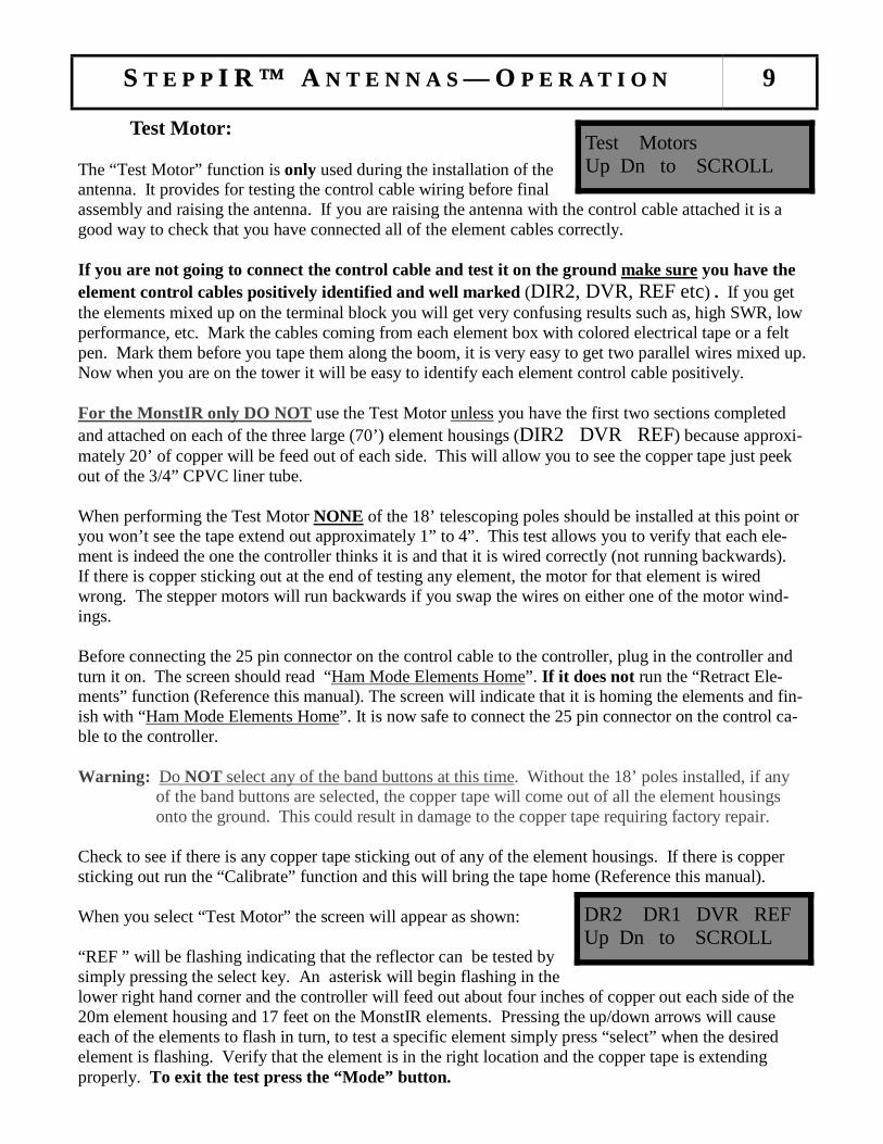
Test Motor: The “Test Motor” function is only used during the installation of the antenna. It provides for testing the control cable wiring before final assembly and raising the antenna. If you are raising the antenna with the control cable attached it is a good way to check that you have connected all of the element cables correctly. If you are not going to connect the control cable and test it on the ground make sure you have the element control cables positively identified and well marked (DIR2, DVR, REF etc) . If you get the elements mixed up on the terminal block you will get very confusing results such as, high SWR, low performance, etc. Mark the cables coming from each element box with colored electrical tape or a felt pen. Mark them before you tape them along the boom, it is very easy to get two parallel wires mixed up. Now when you are on the tower it will be easy to identify each element control cable positively. For the MonstIR only DO NOT use the Test Motor unless you have the first two sections completed and attached on each of the three large (70’) element housings (DIR2 DVR REF) because approxi-mately 20’ of copper will be feed out of each side. This will allow you to see the copper tape just peek out of the 3/4” CPVC liner tube. When performing the Test Motor NONE of the 18’ telescoping poles should be installed at this point or you won’t see the tape extend out approximately 1” to 4”. This test allows you to verify that each ele-ment is indeed the one the controller thinks it is and that it is wired correctly (not running backwards). If there is copper sticking out at the end of testing any element, the motor for that element is wired wrong. The stepper motors will run backwards if you swap the wires on either one of the motor wind-ings. Before connecting the 25 pin connector on the control cable to the controller, plug in the controller and turn it on. The screen should read “Ham Mode Elements Home”. I f it does not run the “Retract Ele-ments” function (Reference this manual). The screen will indicate that it is homing the elements and fin-ish with “Ham Mode Elements Home”. It is now safe to connect the 25 pin connector on the control ca-ble to the controller. Warning: Do NOT select any of the band buttons at this time. Without the 18’ poles installed, if any
of the band buttons are selected, the copper tape will come out of all the element housings onto the ground. This could result in damage to the copper tape requiring factory repair.
Check to see if there is any copper tape sticking out of any of the element housings. If there is copper sticking out run the “Calibrate” function and this will bring the tape home (Reference this manual). When you select “Test Motor” the screen will appear as shown: “REF ” will be flashing indicating that the reflector can be tested by simply pressing the select key. An asterisk will begin flashing in the lower right hand corner and the controller will feed out about four inches of copper out each side of the 20m element housing and 17 feet on the MonstIR elements. Pressing the up/down arrows will cause each of the elements to flash in turn, to test a specific element simply press “select” when the desired element is flashing. Verify that the element is in the right location and the copper tape is extending properly. To exit the test press the “Mode” button.
DR2 DR1 DVR REF Up Dn to SCROLL
Test Motors Up Dn to SCROLL

SSST E P PT E P PT E P P I R ™ AI R ™ AI R ™ A N T E N N A SN T E N N A SN T E N N A S ——— OOO P E R A T I O NP E R A T I O NP E R A T I O N 10
Restoring the Factory Default Antenna Lengths When you use create modify to edit a band (say 20m, normal direction) and save the results, the factory default length for that band in the nor-mal direction is replaced with the new values. This command is used to clear the saved antenna back to the factory defaults. For more information on creating or modifying an-tennas, refer to the creating and modifying antennas section and the saving antennas to memory section of this manual. You can restore the factory default for a specific saved memory or you can completely re-store all of the factory defaults at once. If you want to restore the factory default on a single saved memory, you must first go to that frequency and direction or the saved band button in general frequency mode. Enter the setup mode and select “Factory Defaults” when the controller displays “Current ?” Press Up or Dn until “Yes” is flashing then press select. Multiple master antennas are necessary because the boom length looks longer electrically as you go up in frequency. We have judiciously broken the frequencies up and modeled a unique antenna for each range. This and a smart software algorithm allow an optimal antenna at every frequency without having to model hundreds of antennas. If you create an antenna anywhere within the frequency range of a master antenna the new antenna will be scaled by the software algorithm so you have an antenna with the same performance characteristics throughout that range. To ensure the absolute best performance in the ham bands (any master segment where a ham band occurs) we modeled the master antenna at a frequency near the center of each ham band. So if you are changing a model and create the new antenna near the center of the frequency range, that antenna will then be replicated throughout the entire segment. For example: Let’s say you had replaced the normal direction master antenna for 20M with a new an-tenna length you modeled for maximum gain. Now you have decided that you want the gain / FB combi-nation of the factory default back. To restore the factory default for this example set the controller to nor-mal direction and the frequency anywhere in the 20m band. Leave the antenna at this position, and pro-ceed to the “factory default” menu in the setup mode. Enter the setup mode then press the Up or Dn but-ton until “Factory DEFAULT Current? Yes No” is displayed. Now press either Up or Dn until “Yes” is flashing then press the select key. The factory defaults are now set for the 14.000 MHz segment in the normal Direc-tion only. If you want to re-store all the memories (saved antennas) including the gen-eral mode band buttons at once you will do as before but select “No” when the “Current ?” is displayed. Now the controller will dis-play “All Ant ?” with “No” blinking. If you press select with “Yes” blinking all saved antennas will be reset to the factory defaults. If you press select with “No” flashing you will return to the setup menu.
Factory DEFAULT Current ? Yes No
SSST E P PT E P PT E P P I R ™ AI R ™ AI R ™ A N T E N N A SN T E N N A SN T E N N A S ——— OOO P E R A T I O NP E R A T I O NP E R A T I O N 11
Transceiver Interface (Optional) Note: For retrofit installation information reference Appendix D This menu item is used if you have purchased the optional transceiver interface. To use the transceiver in-terface, you need to have a rig that has computer interfacing capability. Rigs with these options were pri-marily manufactured from 1990 on. When enabled, the transceiver interface on the SteppIR controller will “listen” to your rig through its computer port, and will automatically re-adjust every 50 KHz as you tune through the bands. If you have the transceiver interface option (2 - 9 Pin connectors on the rear of the controller), you will also need an optional interface cable for your specific rig, which has a 9 pin d-sub connector on one end that hooks up to the “Data In” port on the back of the controller. The other end will go to your rigs interface. There is a second 9 pin D-sub connector below the first called “data out”, this connector is used in the event you stack two SteppIR Yagi antennas - it allows the two controllers to communicate with each other, so that when you change frequencies on one of the controllers, the other will follow, or if you want to connect your SteppIR directly to a PC. Note: We can also supply an optional “Y” cable that allows the user to run a logging program concur-
rently with the SteppIR controller. (Not required for ICOM radios) When you first enter setup mode, you will see “Mode key to exit, Up / Dn to SCROLL” on the LCD screen. Press the up button until you see “Transceiver Setup, Up / Dn to scroll”. To enter, press the select button. A new screen will appear saying “Baud Mode Done” with DONE flashing. The baud rate is the speed in which information is exchanged between the SteppIR controller and your ra-dio. This setting must be the same as the setting in your radio, or the interface will not function. To set the baud rate, press the up or down arrow until BAUD is flashing, and then press the select button. You can then use the up or down arrows to adjust to the proper setting. If you are not sure what this setting is, refer to the users manual for your radio. When the proper baud rate is showing, press the select button. BAUD will now be flashing again. Now you will want to set up the mode for the radio type you will be using. Press the up or down arrow un-til MODE is flashing and then press the select button. Now you can use the up or down arrow to scroll through until the proper mode selection is visible. Press the select button, and MODE will be flashing again. (To save refer to Saving Settings below) be sure you set your transceiver up according to your ra-dio manual to broadcast frequency data. Note: => When done the controller power switch must be cycled off then back on for the new settings to
take effect.
=> COM radios require CI-V transceiver mode enabled To use the transceiver interface you must put the controller into “General Frequency” mode. When you tune your rig the SteppIR controller will now automatically re-adjust every 50 KHz. To disable automatic tracking simply select the “Amateur” mode to have full control of the antenna. The controller will be set to the same frequency it was at when you exited General Frequency Mode. It is also possible to disable tracking by using the “Options Menu”.

Saving Settings To save desired settings, use the up or down arrow until DONE is flashing , then press the select button. The controller will ask you if you want to save these settings, and NO will be flashing. If you do not want to save your changes, press the select button while NO is flashing. If you do want to save them, press se-lect while YES is flashing. YOU MUST NOW TURN THE STEPPIR CONTROLLER OFF AND THEN TURN THE CONTROLLER BACK ON AGAIN BEFORE THE SETUP WILL TAKE PLACE . Once this is done, press the mode button until the “General Frequency” LED is lit, and then press select within 2-1/2 seconds. When you tune your rig, the SteppIR controller should now automati-cally re-adjust every 50 KHz. Using the SteppIR controller with your logging program Please refer to the transceiver interface operations for more detailed information.
SSST E P PT E P PT E P P I R ™ AI R ™ AI R ™ A N T E N N A SN T E N N A SN T E N N A S ——— OOO P E R A T I O NP E R A T I O NP E R A T I O N 12
Toni Linden - OH2UA Sets records with SteppIR (Photo Courtesy of Martti Laine OH2BH)
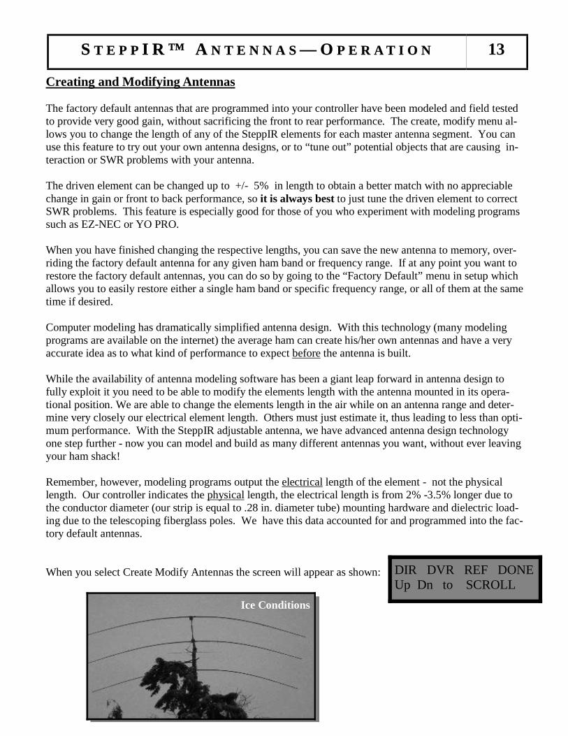
Creating and Modifying Antennas The factory default antennas that are programmed into your controller have been modeled and field tested to provide very good gain, without sacrificing the front to rear performance. The create, modify menu al-lows you to change the length of any of the SteppIR elements for each master antenna segment. You can use this feature to try out your own antenna designs, or to “tune out” potential objects that are causing in-teraction or SWR problems with your antenna. The driven element can be changed up to +/- 5% in length to obtain a better match with no appreciable change in gain or front to back performance, so it is always best to just tune the driven element to correct SWR problems. This feature is especially good for those of you who experiment with modeling programs such as EZ-NEC or YO PRO. When you have finished changing the respective lengths, you can save the new antenna to memory, over-riding the factory default antenna for any given ham band or frequency range. If at any point you want to restore the factory default antennas, you can do so by going to the “Factory Default” menu in setup which allows you to easily restore either a single ham band or specific frequency range, or all of them at the same time if desired. Computer modeling has dramatically simplified antenna design. With this technology (many modeling programs are available on the internet) the average ham can create his/her own antennas and have a very accurate idea as to what kind of performance to expect before the antenna is built. While the availability of antenna modeling software has been a giant leap forward in antenna design to fully exploit it you need to be able to modify the elements length with the antenna mounted in its opera-tional position. We are able to change the elements length in the air while on an antenna range and deter-mine very closely our electrical element length. Others must just estimate it, thus leading to less than opti-mum performance. With the SteppIR adjustable antenna, we have advanced antenna design technology one step further - now you can model and build as many different antennas you want, without ever leaving your ham shack! Remember, however, modeling programs output the electrical length of the element - not the physical length. Our controller indicates the physical length, the electrical length is from 2% -3.5% longer due to the conductor diameter (our strip is equal to .28 in. diameter tube) mounting hardware and dielectric load-ing due to the telescoping fiberglass poles. We have this data accounted for and programmed into the fac-tory default antennas. When you select Create Modify Antennas the screen will appear as shown:
SSST E P PT E P PT E P P I R ™ AI R ™ AI R ™ A N T E N N A SN T E N N A SN T E N N A S ——— OOO P E R A T I O NP E R A T I O NP E R A T I O N 13
DIR DVR REF DONE Up Dn to SCROLL
Ice Conditions

The 4 element antennas have two directors, but you will only see one of them on the LCD screen at any given time. The first Director is labeled Direct 1, the second Direct 2 (See the installation man-ual to determine the location of each on the antenna). To adjust the length of director 2, you simply press the 180 degree button, and it will toggle back and forth between the two directors, showing ei-ther Direct 1 or Direct 2 on the screen. Note: The 2 element and 3 element controllers will also display Direct 2 even though they have only one
director (Direct 1). Make sure you select the correct one. We did this to make our software com-patible across our entire product line.
DIR = Director
DVR = Driven
REF = Reflector
For example, select DIR2 using the 180 button, DIR2 will now be flashing, with the current length shown on the second line. To change this length, press the select button and the display will say Up/Dn to adjust, which means use the up or down arrows to adjust the length of the director to your desired length. Indi-vidual clicks will change the length approximately 0.1” at a time, and if you hold the button down, after a few seconds the controller will ramp up to adjust at 1 inch increments. The elements are changing in real time, so you will see the SWR change as you adjust the element. Once you have reached the desired length, press the select button. DIR will be flashing again, with the new length shown on the second line of the LCD screen. If you want to adjust any or all of the element lengths, you will need to press the up or down arrow until the element of choice is “flashing” and then press the select button. To change the other element lengths, use the up or down arrow until the respective element is “flashing” and repeat the above procedure. When you are finished making adjustments, press the up or down arrow until DONE is flashing again, and press the select button. The screen will read “SAVE? YES NO, with NO flashing. Use the up or down button to make the proper choice (“YES” or “NO”) and press the select button. If you selected “YES”, the new lengths will be saved into memory for the ham band or frequency range you are currently on. After saving your new antenna the controller will scale it and use it through-out the entire ham band or frequency range you created it in. If you create a new antenna or modify the factory default antenna in any of the range segments the controller will then scale that antenna throughout the selected frequency range and only the selected range. Creating and modifying an antenna anywhere (it is best to chose a frequency near the bottom of the range) in a frequency range will change the entire range. You can create the antenna at any frequency within the ham band or general frequency segment, but if you want the very best results model the new antenna in the middle of the band or frequency segment and set the controller to that frequency before creating the antenna. The frequency coverage range of each of our antennas is broken up into numerous blocks for each direction (normal, 180 degree, and bi-directional), each covered by a different antenna model (See “Master Antenna Frequency Range Chart”). Using the create antenna mode you can modify and save any of the master antennas (Table 4 or 5). The frequency range is identical for the all three direction modes of the antenna (normal, 180 degrees, and bi-directional). If you select “NO”, no changes will be made, your antenna segment will be just as it was before.
SSST E P PT E P PT E P P I R ™ AI R ™ AI R ™ A N T E N N A SN T E N N A SN T E N N A S ——— OOO P E R A T I O NP E R A T I O NP E R A T I O N 14
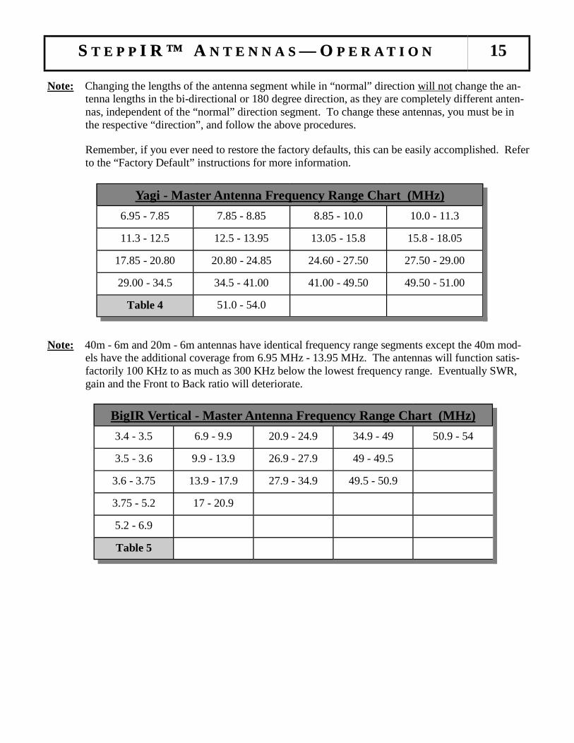
Note: Changing the lengths of the antenna segment while in “normal” direction will not change the an-tenna lengths in the bi-directional or 180 degree direction, as they are completely different anten-nas, independent of the “normal” direction segment. To change these antennas, you must be in the respective “direction”, and follow the above procedures.
Remember, if you ever need to restore the factory defaults, this can be easily accomplished. Refer to the “Factory Default” instructions for more information.
Note: 40m - 6m and 20m - 6m antennas have identical frequency range segments except the 40m mod-
els have the additional coverage from 6.95 MHz - 13.95 MHz. The antennas will function satis-factorily 100 KHz to as much as 300 KHz below the lowest frequency range. Eventually SWR, gain and the Front to Back ratio will deteriorate.
SSST E P PT E P PT E P P I R ™ AI R ™ AI R ™ A N T E N N A SN T E N N A SN T E N N A S ——— OOO P E R A T I O NP E R A T I O NP E R A T I O N 15
6.95 - 7.85 7.85 - 8.85 8.85 - 10.0 10.0 - 11.3
11.3 - 12.5 12.5 - 13.95 13.05 - 15.8 15.8 - 18.05
17.85 - 20.80 20.80 - 24.85 24.60 - 27.50 27.50 - 29.00
29.00 - 34.5 34.5 - 41.00 41.00 - 49.50 49.50 - 51.00
Table 4 51.0 - 54.0
Yagi - Master Antenna Frequency Range Chart (MHz)
3.4 - 3.5 6.9 - 9.9 20.9 - 24.9 34.9 - 49 50.9 - 54
3.5 - 3.6 9.9 - 13.9 26.9 - 27.9 49 - 49.5
3.6 - 3.75 13.9 - 17.9 27.9 - 34.9 49.5 - 50.9
3.75 - 5.2 17 - 20.9
5.2 - 6.9
Table 5
BigIR Vertical - Master Antenna Frequency Range Chart (MHz)
Calibrating the Antenna Calibrating the antenna ensures that the element lengths are exactly what the controller display says they are. Usually, the only way the antenna can get out of calibration is if the power is interrupted or the cable is somehow disconnected while the antenna is changing length. The controller does not “know” where the antenna is adjusted to unless you start at a known place. The antenna housing sent to you has each element retracted inside to “Home”, and the controller is set to “Elements Home”. If you power up the controller and it says “Elements Home”, and you connect the antenna control cable with the elements physically retracted, you are calibrated and ready to go! If you need to calibrate, it is a simple, two click operation. When you select calibrate, the antenna will re-tract all of the elements, and the stepper motor will continue to over-step for up to 50 seconds after the elements have retracted. In doing this, the controller is making sure that there is not a shadow of a doubt that each element is fully retracted, and back to the known starting point. When calibrating, you will hear a buzzing noise for as much as 50 seconds, this is normal. When calibration is finished, the antenna will go to the last frequency you were on before you started the calibration process. The entire process takes less than a minute. Note: Whenever your antenna is not acting as it should, we highly recommend that you use the
calibrate function before exploring other potential problems. Always calibrate when in doubt - it is easy, and doesn’t hurt a thing! It doesn’t matter what frequency you are on when you calibrate, when complete the antenna is calibrated at all frequencies.
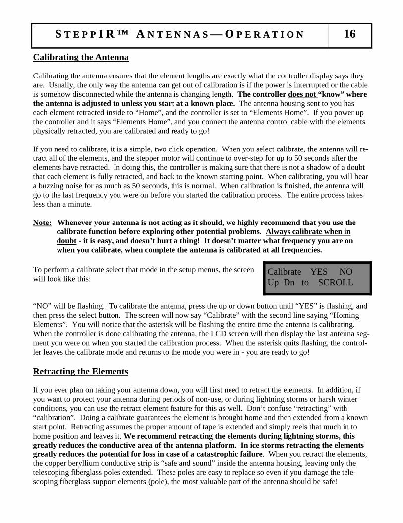
To perform a calibrate select that mode in the setup menus, the screen will look like this: “NO” will be flashing. To calibrate the antenna, press the up or down button until “YES” is flashing, and then press the select button. The screen will now say “Calibrate” with the second line saying “Homing Elements”. You will notice that the asterisk will be flashing the entire time the antenna is calibrating. When the controller is done calibrating the antenna, the LCD screen will then display the last antenna seg-ment you were on when you started the calibration process. When the asterisk quits flashing, the control-ler leaves the calibrate mode and returns to the mode you were in - you are ready to go! Retracting the Elements If you ever plan on taking your antenna down, you will first need to retract the elements. In addition, if you want to protect your antenna during periods of non-use, or during lightning storms or harsh winter conditions, you can use the retract element feature for this as well. Don’t confuse “retracting” with “calibration”. Doing a calibrate guarantees the element is brought home and then extended from a known start point. Retracting assumes the proper amount of tape is extended and simply reels that much in to home position and leaves it. We recommend retracting the elements during lightning storms, this greatly reduces the conductive area of the antenna platform. In ice storms retracting the elements greatly reduces the potential for loss in case of a catastrophic failure. When you retract the elements, the copper beryllium conductive strip is “safe and sound” inside the antenna housing, leaving only the telescoping fiberglass poles extended. These poles are easy to replace so even if you damage the tele-scoping fiberglass support elements (pole), the most valuable part of the antenna should be safe!
SSST E P PT E P PT E P P I R ™ AI R ™ AI R ™ A N T E N N A SN T E N N A SN T E N N A S ——— OOO P E R A T I O NP E R A T I O NP E R A T I O N 16
Calibrate YES NO Up Dn to SCROLL

To select the home Elements” command in the Setup Menu the screen will appear as shown with “NO” flashing. The controller is asking you if you want to send the elements “home”, which means retracting the ele-ments inside the antenna housing. To retract the antenna, press the up or down button once, and YES will start flashing. Press the select button, the display will say “Home Now? / Homing Elements”. The asterisk will be flashing, this means that the antenna is retracting, when the asterisk disappears, the new message will read “Ham Mode Elements Home”. Your antenna is now safely inside the antenna housings. When you want to put the antenna back on the air, simply press the antenna segment you de-sire, and the controller will adjust to that segment.
Normal, 180 Degree and Bi-Directional Function The 180 degree mode feature is one of the most popular among SteppIR users. The 180 degree mode allows you to electrically “rotate” the antenna 180 degrees from your current “normal” direction beam heading. This is done by simply pressing a button, and in 2-1/2 seconds (quicker on higher frequen-cies, longer on lower) the transformation is complete. The existing reflector becomes a director and the director becomes a reflector, and you now have a completely different antenna in the exact opposite direction. With the two element Yagi, the director becomes a reflector. In addition to greatly reducing your rotator use, many SteppIR users report that the 180 degree function is an excellent tool for short path / long path operation, or for picking up that elusive multiplier in the heat of a contest! At SteppIR, we think the best use for this function is when we want to show off the great front to back performance of the antenna! The bi-directional function operates in a similar manner, except when enabled, you are now operating with gain in opposite directions. You will have approximately 2 db less gain than normal but now you have gain in both the forward and reverse direction. This feature can be very handy for those who are involved with net operation or ham contests where hearing (or sending) signals from two directions can give you an advantage. The direction button is located to the right of the LCD display. The button is a 3 way toggle, meaning that each time you press the button it will move to the next position. When no LED’s are lit, this means you are in the forward, or “normal” operating direction. If the 180° LED is lit, the direction of the antenna is now 180 degrees from normal, or the exact opposite direction of where you were pointed at before. If the Bi-Dir LED is lit, you now are operating with gain in both direction. Be aware the power on LED is easy to confuse with the Bi-directional LED. Saving Antennas to Memory In addition to creating or modifying antennas, you can also save specific frequencies that you may want to access repeatedly. You can save up to 6 different frequencies and access them in the general frequency mode. For example, if you wanted to save WWV on 15.000 MHz into memory so that you could access it quickly, you would first go to general frequency mode, and press the “select” button. From there, you could either hold either the up or down arrow until you reached WWV at 15.000, or you could press one of the band buttons to get you close to the destination frequency and then use the up or down arrow to dial it in the rest of the way. This brings up an important point for manually op-erating in the general frequency mode.
SSST E P PT E P PT E P P I R ™ AI R ™ AI R ™ A N T E N N A SN T E N N A SN T E N N A S ——— OOO P E R A T I O NP E R A T I O NP E R A T I O N 17
Home Now? YES NO Up Dn to SCROLL

In the general frequency mode, there are a total of 6 different memories. Each individual band button has 3 memories - a memory for the forward direction, a memory for the 180 degree direction, and a third memory for the bi-directional mode (Remember, these are all separate antennas, independent of each other). You can replace the factory default frequency with a new frequency at any of six band buttons. We will use our example of WWV at 15.000 MHz to explain the procedure. While in general frequency mode, set the controller to “normal” direction and tune the controller to 15.000 MHz as explained above. In this case, we are going to save the new frequency on the 20m but-ton. Press the 20m button and hold it down for a few seconds. The LED will start to flash. Let up on the 20m button, and then immediately press it again. A 15.000 MHz antenna is now saved under the 20m “normal” direction button. Next select the 180 degree mode and repeat the above procedure. Finally select Bi-directional mode and repeat again. If you don’t change the frequency to 15.000 MHz in the 180 degree and Bi-directional modes the controller will revert to the factory default frequency, or to the last saved frequency when you try to use either mode.
SSST E P PT E P PT E P P I R ™ AI R ™ AI R ™ A N T E N N A SN T E N N A SN T E N N A S ——— OOO P E R A T I O NP E R A T I O NP E R A T I O N 18

Appendix A: SteppIR Performance
SteppIR antennas are developed by first modeling the antenna using YO-PRO and EZ-NEC. We cre-ated antennas that had maximum gain and front to rear. The antennas that reside in our controllers memory are all optimized for gain and front to rear with a ra-diation resistance of approximately 22 ohms (16 ohms to 30 ohms is considered ideal for real world yagis). The modeling also takes into account the changing electrical boom length as frequency changes. When the 180 degree function is enabled, a new Yagi is created that takes into account the change in element spacing and in the case of 4 element antennas creating a two reflector antenna to get maximum use of all elements . The result is slightly different gain and front to rear specifications. We then go to the antenna range and correlate the modeled antenna to the real world. In other words, we determine as closely as possible the electrical length of the elements. We are very close to the mod-eled antennas, but it is virtually impossible to get closer than a few tenths of a dB on gain and several dB on front to rear. There are three factors that make our antennas outstanding performers:
1. They are tuned to a specific frequency for maximum gain and front to rear – without the com-promise in performance that tuning for bandwidth causes.
2. They are very efficient antennas with high conductivity conductors, a highly efficient matching system (99% plus) and low dielectric losses.
3. There are no inactive elements, traps or linear loading to reduce antenna performance.
Fixed Element Spacing and the SteppIR Yagi First of all, there really is no "ideal" boom length for a Yagi. To get maximum gain the boom of a three element beam should be right around .4 wavelengths long. This would allow a free space gain of 9.7 dBi, however the front to back ratio is compromised to around 11 dB. If the boom is made shorter, say .25 wavelengths, the front to back can be as high as 25 dB, but now the maximum gain is about 8.0 dBi. Shorter booms also limit the bandwidth, which is why right around .3 wavelengths is considered the best compromise for gain, front to back and bandwidth for a fixed element length yagi. It turns out that being able to tune the elements far outweighs being able to choose boom length. We chose 16 feet for our three element boom length which equates to .23 wavelength on 20 meters and .46 wavelength on 10 meters, because very good Yagi’s can be made in that range of boom length if you can adjust the element lengths. This compromise works out very well because 10m is a large band and F/B isn’t as important so you get excellent gain with still very acceptable F/B. When bandwidth is of no concern to you (as it is with our antenna), you can construct a Yagi that is the very best compromise on that band and then track that performance over the entire band. It is this ability to move the performance peak that makes the SteppIR actually outperform a mono-bander over an entire band – even when the boom length isn’t what is classically considered "ideal". Bear in mind that a Yagi rarely has maximum gain and maximum front to back at the same time, so it is always a compromise between gain and front to back. This is the same philosophy we use on all of our yagi antennas to give you the most performance available for a given boom length. With an adjustable antenna you can choose which parameter is important to you in a given situation. For example, you might want to have a pile-up buster saved in memory, that gets you that extra .5 – 1.0 dB of gain at the expense of front to back and SWR – when you are going after that rare DX!
SteppIR Performance 19

SteppIR Performance 20
RF Power Transmission with the SteppIR Yagi The RF power is transferred by brushes that have 4 contact points on each element that results in a very low impedance connection that is kept clean by the inherent wiping action. The brush contact is .08 in thick and has proven to last over 2 million band changes. The copper beryllium tape is .545 inches wide and presents a very low RF impedance. The type of balun we are using can handle tremendous amounts of power for their size because there is almost no flux in the core and they are 99% efficient. That coupled with the fact that our antenna is always at a very low VSWR means the balun will handle much more than the 3000 watt rating, how much more we don't know. Jerry Sevicks book "Transmission Transformers" (available from ARRL) has a chapter (Chap. 11) that discusses the power handling ability of ferrite core transformers. WARNING: WHEN OPERATING WITH MORE THAN 200 WATTS, DO NOT TRANSMIT
WHILE THE ANTENNA IS CHANGING BANDS. A MISMATCH, WHILE MOVING THE ELEMENTS AT ELEVATED WATTAGES, MAY CAUSE DAM-AGE TO THE DRIVEN ELEMENT.
Balun / Matching System The SteppIR has a matching system that is included in the 2 element, 3 element, 4 element and MonstIR Yagi (a balun is available as an option on the dipole). Our antenna designs are all close to 22 ohms at all frequencies, so we needed a broadband matching system that would transform 22 ohm to 50 ohm. We found an excellent one designed by Jerry Sevick, that is described in his book “Building and Using Baluns and Ununs”. Our matching network is a transmission line transformer that is wound on a 2.25 inch OD ferrite core that operates with very little internal flux, thus allowing it to function at very high power levels. The transformer includes a 22 ohm to 50 ohm unun and a balun wound with custom made, high power, 25 ohm coax for superior balun operation. Jerry has espoused these transformers for years as an overlooked but excellent way to match a Yagi, he would probably be proud to know they are being used in a com-mercial Yagi. This matching network does not require compressing or stretching a coil, or separating wires to get a good match – something that can easily be bumped out of adjustment by birds or installa-tion crews.
Balun

Yagi Troubleshooting Guide 21
Appendix B: The Most Common Problems
(Read this First!) ● The antenna is out of calibration, perform the calibration as described in the manual. ● The factory defaults have been inadvertently changed, reset factory defaults “all”. There are two
default modes, “all” and “current”. “Current” only resets the band segment you are currently on. ● The control cable is miss-wired. ● Interaction between power lines, other antennas, metal roofs, house wiring, gutters, etc, and the an-
tenna. ● The automatic tuner is enabled on your rig, your linear or your external tuner that is in line. ● Your antenna selector is on the wrong antenna, check the coax cable at the shack end with an ohm
meter, it should read very close to a dead short. ● Your rig is in the split mode and worse case, to a different band! ● A low pass filter is in line and 6 meters has very high SWR. ● Your in-line linear has a transmit / receive switch some of which may be poorly designed or
faulty. This can make the SWR give incorrect higher readings. Remove as many things in-line on
the coax as possible so you get a more accurate SWR reading. ● Low cost SWR meters, especially those built into transceivers, can give incorrect readings, both
higher and lower than reality. They also can be drastically affected by the length of the coax line.
Removing a few feet of line can cause drastic differences in the reading ranging from 10% to as
much as 100% ! Directional couplers such as the Bird watt meter or antenna analyzers are much
more reliable. Make sure you really have a problem before you hit the panic button. ● Blown driver board from shorting any of the wires in the control cable with power plugged into the
controller. Even with the power button pushed “off” the cable is energized. ● Broken or damaged control cable or connector. See Cable Problems section. ● Bad coax or coax connector. We have seen bad coax that an analyzer said was good. Substitution
is the sure way. ● Damaged driver board is pulling power supply voltage down causing the microprocessor to mal-
function. Check to see if the green LED is lit on power supply ● Ground the controller, this prevents crashes of the microprocessor and provides a path for static
discharge. ● The rubber plugs that were installed in the telescoping poles for shipping and handling purposes
were not removed. ● PL-259 was not tightened with PLIERS – Do NOT trust your fingers – This is a common problem ● Miss-wire causing the stepper motor on one or more elements to run backwards
Yagi Troubleshooting Guide 22
GENERAL: Be aware that just because the controller display says an element is a certain length there is no guaran-tee that it is, the motor could be running backwards due to a miss-wire, the element could have me-chanical problems, or a broken wire in the control cable (the motor will run with only one winding driven in some cases) or a faulty driver board. The controller runs open loop and has no way of know-ing if the element is really moving. The motors in the elements make three distinct noises: 1. A ratcheting sound lasting 1 – 2 seconds at the start and finish of the motor running. This is the
rpm ramp-up the stepper motors require and is normal. 2. A smooth whirring sound indicating normal operation. 3. A loud rattling sound that sounds like gears slipping indicates the stepper motor is stalling. This
occurs during the middle portion of a “calibrate” with the smooth running sound before and after it and is normal. Any other time (even for brief durations) this noise indicates unwanted stalling of the motor and should be investigated.
Check the resistance with an ohmmeter between the center conductor and ground of the coax con-nected to the antenna, it should read zero ohms. HIGH SWR: Whenever the antenna has a problem you will most likely observe higher than expected SWR. How-ever, this is not always the case, as there are many situations where the SWR looks good but one ele-ment on the antenna may not be working at all. This is what makes it so difficult to diagnose prob-lems, and why we emphasis building and wiring the antenna carefully. In our experience an SWR of 1.4:1 or less is normal. In most cases the lowest SWR will not be at the same frequency as the best performance. This is because we have optimized the antenna for performance first, SWR second. If the problem is with the driven element the SWR can be very high (over 3:1 and as high as 10:1). If the problem is with a passive element the SWR will not be over about 3:1 no matter how far off the passive element is. INTERACTION PROBLEMS: The most common reason for higher than expected or shifted SWR is unexpected interactions. Usually only one or two bands are affected but not always, and the antenna will probably have reasonable gain and front to back. It is important to take good notes, so if you need to call us we can do a better job of helping you. Record the SWR on each band and each direction mode at least one place in the band, this is a good idea anyway so you can assess the health of your antenna over time. Rotate the antenna and look for changes in SWR greater than .2 or so, this indicates interaction if it changes very much. The usual culprits are wire antennas, other nearby antennas, gutters, power lines, house wiring, metal-lic guy wires, etc. If the SWR is not too high you can “tune” it out by using the “Create, Modify” mode to adjust only the driven element for best SWR and save it as described in the manual. Don’t adjust the passive elements to improve SWR it will degrade the performance. Adjusting the driven ele-ment won’t. Otherwise you will need to change your installation to reduce the interaction to an accept-able level.
Yagi Troubleshooting Guide 23
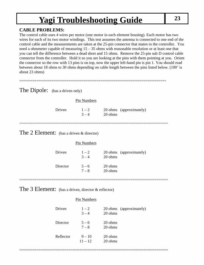
CABLE PROBLEMS: The control cable uses 4 wires per motor (one motor in each element housing). Each motor has two wires for each of its two motor windings. This test assumes the antenna is connected to one end of the control cable and the measurements are taken at the 25-pin connector that mates to the controller. You need a ohmmeter capable of measuring 15 – 35 ohms with reasonable resolution or at least one that you can tell the difference between a dead short and 15 ohms. Remove the 25-pin sub D control cable connector from the controller. Hold it so you are looking at the pins with them pointing at you. Orient the connector so the row with 13 pins is on top, now the upper left-hand pin is pin 1. You should read between about 18 ohms to 30 ohms depending on cable length between the pins listed below. (100’ is about 23 ohms) ==============================================================================
The Dipole: (has a driven only) Pin Numbers Driven 1 – 2 20 ohms (approximately) 3 – 4 20 ohms ===============================================================================
The 2 Element: (has a driven & director) Pin Numbers Driven 1 – 2 20 ohms (approximately) 3 – 4 20 ohms Director 5 – 6 20 ohms 7 – 8 20 ohms ===============================================================================
The 3 Element: (has a driven, director & reflector) Pin Numbers Driven 1 – 2 20 ohms (approximately) 3 – 4 20 ohms Director 5 – 6 20 ohms 7 – 8 20 ohms Reflector 9 – 10 20 ohms 11 – 12 20 ohms ===============================================================================
Yagi Troubleshooting Guide 24
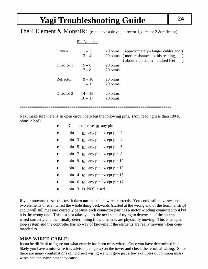
The 4 Element & MonstIR: (each have a driven, director 1, director 2 & reflector) Pin Numbers Driven 1 – 2 20 ohms ( approximately - longer cables add ) 3 – 4 20 ohms ( more resistance to this reading, ) ( about 2 ohms per hundred feet ) Director 1 5 – 6 20 ohms 7 – 8 20 ohms Reflector 9 – 10 20 ohms 11 – 12 20 ohms Director 2 14 – 15 20 ohms 16 – 17 20 ohms =============================================================================== Next make sure there is an open circuit between the following pins. (Any reading less than 100 K ohms is bad) ● Connector case to any pin ● pin 1 to any pin except pin 2 ● pin 3 to any pin except pin 4 ● pin 5 to any pin except pin 6 ● pin 7 to any pin except pin 8 ● pin 9 to any pin except pin 10 ● pin 11 to any pin except pin 12 ● pin 14 to any pin except pin 15 ● pin 16 to any pin except pin 17 ● pin 13 is NOT used
If your antenna passes this test it does not mean it is wired correctly. You could still have swapped two elements or even wired the whole thing backwards (started at the wrong end of the terminal strip) and it will still measure correctly because each connector pair has a motor winding connected to it but it is the wrong one. This test just takes you to the next step of trying to determine if the antenna is wired correctly and then finally determining if the elements are physically moving. This is an open loop system and the controller has no way of knowing if the elements are really moving when com-manded to. MISS-WIRED CABLE: It can be difficult to figure out what exactly has been miss-wired. Once you have determined it is likely you have a miss-wire it is advisable to go up on the tower and check the terminal wiring. Since there are many combinations of incorrect wiring we will give just a few examples of common miss-wires and the symptoms they cause.
Yagi Troubleshooting Guide 25
• Two or More Elements are Swapped: This is easy to do if you don’t mark the 4 conductor cables before you tape them along the boom. The SWR will usually be high on every band. Often by changing the controller frequency, while keeping the transmit frequency fixed, the SWR may go quite low at a higher or lower controller frequency. In any case of SWR problems don’t be surprised if the SWR is okay when you switch to the 180 degree mode. If it isn’t good in the forward mode you have a problem.
• If you Suspect Elements are Swapped: First try to identify which one is the driven element. You can identify the driven element easily be-cause it has a much greater effect on SWR than the passives do. The driven element is also very easy to identify by retracting all of the elements and then use “Create, Modify” to extend each element indi-vidually until signals are heard in the receiver. Obviously you will only hear signals when the driven element is extended. The best way to determine if the passives are switched is to point the antenna in the normal mode at a station you know the location of and then switch the antenna to 180-degree mode, if he gets stronger you probably have switched the passives. If it seems like they are switched you can use “Create, Modify” mode to “swap” the elements back by first recording what the controller says each one should be and then go put the reflector length into the director and vice-versa for the di-rector. If the antenna now works normally you have swapped the cables of the two passives and will need to correct the wiring.
• One or More Elements are not Moving: If the driven is not moving you will have very high SWR at all frequencies. However, it may have stopped at some length and you might have good SWR only at one particular frequency. Set the con-troller to 14.200 MHz and monitor the SWR at that frequency. Next go into the “Create, Modify ” mode and vary each element length and monitor the SWR while you do it and watch for dramatic changes (.5 SWR change, minimum). Warning: Keep your transmit wattage as low as possible during this test, to prevent any possible
damage to your radio from a potential mismatch. When you adjust the driven element driven you should be able to get an SWR of 5:1 or greater. Al-ways return the element you have just tested to its original length before testing the next one. The pas-sive elements can only cause an SWR of 3.5:1 maximum no matter what length you make them. Ad-just the passive elements from minimum length to maximum length and you should see at least a .5 change at some point. When the passive element is near the length of the driven element interaction is the greatest and you should see a very noticeable change in SWR. You will find that Director 2 (on 4 element models) has much less of an affect on the SWR because it is so far away from the driven ele-ment, but you should still see at least a .4 change in the SWR reading. A classic symptom of one pas-sive element not moving is a high SWR in the normal direction and a markedly better SWR in the 180 direction. If any element does not affect the SWR the cause is one of the following: ● Bad or intermittent cable, check it again. ● Damaged driver board in the controller ● Mechanical problem with the element
Be aware that lightning or shorting the cable can partially disable a driver chip and it will still limp along moving the tape but you will see inconsistent SWR when changing from band to band.
Yagi Troubleshooting Guide 26
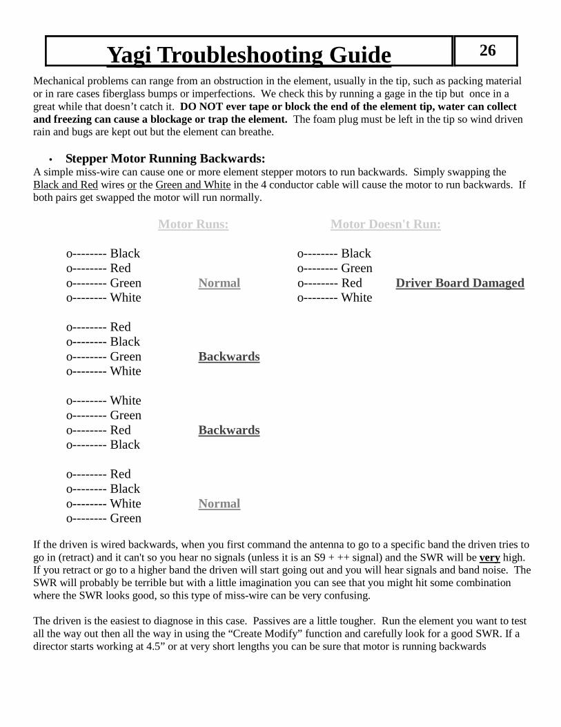
Mechanical problems can range from an obstruction in the element, usually in the tip, such as packing material or in rare cases fiberglass bumps or imperfections. We check this by running a gage in the tip but once in a great while that doesn’t catch it. DO NOT ever tape or block the end of the element tip, water can collect and freezing can cause a blockage or trap the element. The foam plug must be left in the tip so wind driven rain and bugs are kept out but the element can breathe.
• Stepper Motor Running Backwards: A simple miss-wire can cause one or more element stepper motors to run backwards. Simply swapping the Black and Red wires or the Green and White in the 4 conductor cable will cause the motor to run backwards. If both pairs get swapped the motor will run normally. Motor Runs: Motor Doesn't Run: o-------- Black o-------- Black o-------- Red o-------- Green o-------- Green Normal o-------- Red Driver Board Damaged o-------- White o-------- White o-------- Red o-------- Black o-------- Green Backwards o-------- White o-------- White o-------- Green o-------- Red Backwards o-------- Black o-------- Red o-------- Black o-------- White Normal o-------- Green If the driven is wired backwards, when you first command the antenna to go to a specific band the driven tries to go in (retract) and it can't so you hear no signals (unless it is an S9 + ++ signal) and the SWR will be very high. If you retract or go to a higher band the driven will start going out and you will hear signals and band noise. The SWR will probably be terrible but with a little imagination you can see that you might hit some combination where the SWR looks good, so this type of miss-wire can be very confusing. The driven is the easiest to diagnose in this case. Passives are a little tougher. Run the element you want to test all the way out then all the way in using the “Create Modify” function and carefully look for a good SWR. If a director starts working at 4.5” or at very short lengths you can be sure that motor is running backwards

Vertical Troubleshooting Guide 27
Appendix C: The Most Common Problems
(Read this First!) ● The antenna is out of calibration, perform the calibration as described in the manual. ● The antenna length needs to be adjusted due to height above ground or more radials added. Any
length of wire to the radial junction point adds directly to the antenna length. Keep the lead to 12”
or less. ● The control cable is miss-wired. ● Interaction between power lines, other antennas, metal roofs, house wiring, gutters, etc, and the
antenna. ● The automatic tuner is enabled on your rig, your linear or your external tuner is inline. ● Elevated mounting is much trickier than ground mounting. Read the manual section that discusses
elevated mounting. ● Your antenna selector is on the wrong antenna ● Your rig is in the split mode and worse case, to a different band! ● A low pass filter is in line and 6 meters has very high SWR. ● Your inline linear has a transmit / receive switch some of which may be poorly designed or faulty.
This can make the SWR give incorrect higher readings. Remove as many things in-line on the
coax as possible so you get a more accurate SWR reading. ● Blown driver board from shorting the wires together in the control cable with power plugged into
the controller. Even with the power button pushed “off” the cable is energized. ● Low cost SWR meters, especially those built into transceivers, can give incorrect readings, both
higher and lower than reality. They also can be drastically affected by the length of the coax line.
Removing a few feet of line can cause drastic differences in the reading ranging from 10% to as
much as 100% ! Directional couplers such as the Bird watt meter or antenna analyzers are much
more reliable. Make sure you really have a problem before you hit the panic button. ● Broken or damaged control cable or connector. See Cable Problems section. ● Bad coax or coax connector. ● Damaged driver board is pulling power supply voltage down causing the microprocessor to
malfunction. Check to see if green LED is lit on power supply ● Ground the controller, this prevents crashes of the microprocessor and provides a path for static
discharge. ● PL-259 was not tightened with pliers - (do this just like the yagi section)
Vertical Troubleshooting Guide 28
GENERAL: Be aware that just because the controller display says an element is a certain length there is no guarantee that it is, the element could have mechanical problems, or a broken wire in the control cable (the motor will run with only one winding driven in some cases) or a faulty driver board. The controller runs open loop and has no way of knowing if the element is really moving. The motors in the elements make three distinct noises: 1. A ratcheting sound lasting 1 – 2 seconds at the start and finish of the motor running, this is the ramp-
up stepper motors require and is normal. 2. A smooth whirring sound indicating normal operation. 3. A loud rattling sound that sounds like gears slipping indicates the stepper motor is stalling. This
occurs during the middle portion of a “calibrate” with the smooth running sound before and after it and is normal. Any other time (even for brief durations) this noise indicates unwanted stalling of the motor and should be investigated.
Check the resistance with an ohmmeter between the center conductor and ground of the coax connected to the antenna, it should read zero ohms. High SWR: Whenever the antenna has a problem you will most likely observe higher than expected SWR. In our experience an SWR of 1.5:1 or less is normal.
INTERACTION PROBLEMS: The most common reason for higher than expected or shifted SWR is objects in the near field. Usually only one or two bands are affected but not always. It is important to take good notes so if you need to call us we can do a better job of helping you. Record the SWR on each band at least one place in the band, this is a good idea anyway so you can assess the health of your antenna over time. The usual culprits are slopers, other nearby antennas, gutters, power lines, house wiring, metallic guy wires, etc. You can usually tune out high SWR by using the “Create, Modify” mode to adjust only the driven element for best SWR and save it as described in the manual. Otherwise you will need to change your installation to reduce the interaction to an acceptable level.
CABLE PROBLEMS:
The control cable uses 4 wires per motor (one motor is in the element), 2 wires for each of the two motor windings. This test assumes the antenna is connected to one end of the control cable and the measurements are taken at the 25-pin connector that mates to the controller. You need an ohmmeter capable of measuring 15 – 35 ohms with reasonable resolution or at least one that you can tell the difference between a dead short and 15 ohms. Remove the 25-pin subD control cable connector from the controller. Hold it so you are looking at the pins with them pointing at you. Orient the connector so the row with 13 pins is on top, now the upper left-hand pin is pin 1. You should read between about 18 ohms to 30 ohms (depends on cable length, 100’ is about 23 ohms) between the pins listed below.
Vertical Troubleshooting Guide 29
Pin Numbers Driver 1 – 2 20 ohms (approximately) 3 – 4 20 ohms Next make sure there is an open circuit (> 100 K ohms) between the following pins: ● Connector case to pins 1, 2, 3 or 4
• Pins 1 - 3
Antenna is off frequency: It is hard to predict where the best length will be on the vertical so it almost always requires some adjustment to get the lowest SWR at the proper frequency. Set the vertical to the same frequency as the radio and use the Create modify mode to adjust the driver length for the best SWR, this will need to be done for each band. The nature of the vertical is that if there is a problem with the motor housing or conductor strip it will show up when you use the antenna on 40M. If the antenna is off frequency on 20M after going to 40M and doing the setup mode calibrate or the home commands fix the problem on 20M the motor housing needs service. The connection wire to your radial system should be kept to 12” or less. The length of the wire adds directly to the length of the antenna. This is not a problem to tune out by adjusting the element length but it also affects the feed point impedance. It is like using an offset feed point and if you allow the length of the radial connection lead to get too long you will not be able to get a good match. Element is not Moving: If the element is not moving you will have very high SWR at all frequencies. However, it may have stopped at some length and you might have good SWR only at one particular frequency. Next go into the “Create, Modify” mode and vary the element length and monitor the SWR while you do it (100 watts or less is okay) and watch for dramatic changes (.5 SWR change, minimum). When you adjust the driven element you should be able to get an SWR of 2:1 or less. If adjusting the element does not affect the SWR the cause is one of the following: ● Bad or intermittent cable, check it again. ● Damaged driver board in the controller ● Mechanical problem with the element
Be aware that lightning or shorting the cable can partially disable a driver chip and it will still limp along moving the tape but you will see inconsistent SWR when changing from band to band. Mechanical problems can range from an obstruction in the element, usually in the tip, such as packing ma-terial or in rare cases fiberglass bumps or imperfections. We check this by running a gauge in the tip but once in a great while that doesn’t catch it.
Transceiver Interface Installation 30
Appendix D:
Note: These instructions are only needed if you bought the serial interface sepa-
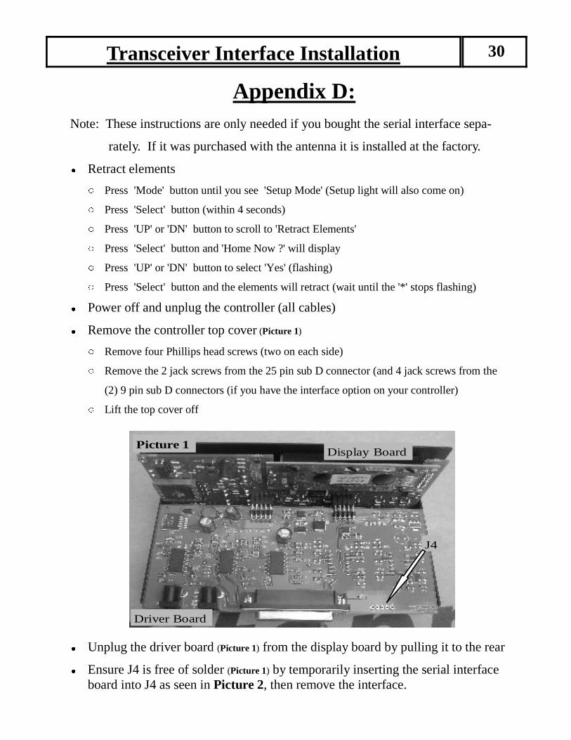
rately. If it was purchased with the antenna it is installed at the factory. ● Retract elements ○ Press 'Mode' button until you see 'Setup Mode' (Setup light will also come on) ○ Press 'Select' button (within 4 seconds) ○ Press 'UP' or 'DN' button to scroll to 'Retract Elements' ○ Press 'Select' button and 'Home Now ?' will display ○ Press 'UP' or 'DN' button to select 'Yes' (flashing) ○ Press 'Select' button and the elements will retract (wait until the '*' stops flashing) ● Power off and unplug the controller (all cables) ● Remove the controller top cover (Picture 1) ○ Remove four Phillips head screws (two on each side) ○ Remove the 2 jack screws from the 25 pin sub D connector (and 4 jack screws from the
(2) 9 pin sub D connectors (if you have the interface option on your controller) ○ Lift the top cover off
● Unplug the driver board (Picture 1) from the display board by pulling it to the rear ● Ensure J4 is free of solder (Picture 1) by temporarily inserting the serial interface board into J4 as seen in Picture 2, then remove the interface.
Driver Board
Display Board Picture 1
J4
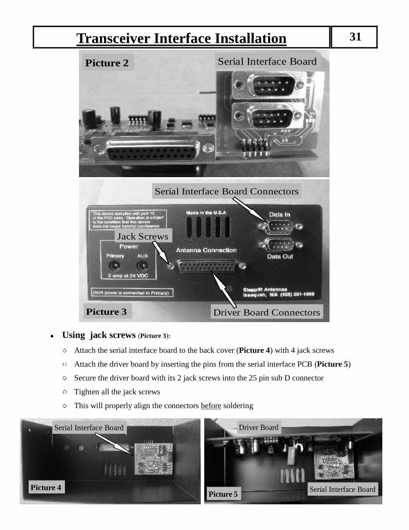
Transceiver Interface Installation 31
Picture 2 Serial Interface Board
Serial Interface Board Connectors
Picture 3 Driver Board Connectors
Jack Screws
● Using jack screws (Picture 3): ○ Attach the serial interface board to the back cover (Picture 4) with 4 jack screws ○ Attach the driver board by inserting the pins from the serial interface PCB (Picture 5) ○ Secure the driver board with its 2 jack screws into the 25 pin sub D connector ○ Tighten all the jack screws ○ This will properly align the connectors before soldering
Serial Interface Board
Picture 4 Picture 5
Serial Interface Board
Driver Board
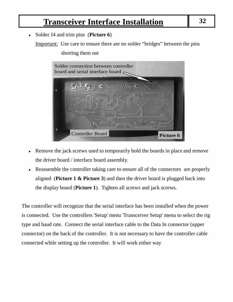
Transceiver Interface Installation 32 ● Solder J4 and trim pins (Picture 6)
Important: Use care to ensure there are no solder “bridges” between the pins
shorting them out
● Remove the jack screws used to temporarily hold the boards in place and remove
the driver board / interface board assembly. ● Reassemble the controller taking care to ensure all of the connectors are properly
aligned (Picture 1 & Picture 3) and then the driver board is plugged back into
the display board (Picture 1). Tighten all screws and jack screws.
The controller will recognize that the serial interface has been installed when the power
is connected. Use the controllers 'Setup' menu 'Transceiver Setup' menu to select the rig
type and baud rate. Connect the serial interface cable to the Data In connector (upper
connector) on the back of the controller. It is not necessary to have the controller cable
connected while setting up the controller. It will work either way
Controller Board
Solder connection between controller board and serial interface board
Picture 6
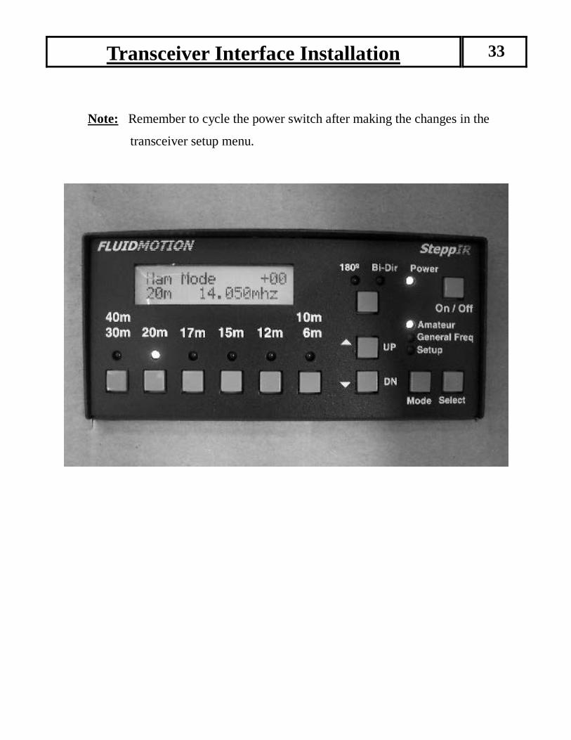
Transceiver Interface Installation 33
Note: Remember to cycle the power switch after making the changes in the
transceiver setup menu.

APPENDIX E
Firmware Chip Replacement Procedures
Please read these instructions first before replacing firmware chip . The following procedure will demonstrate the proper removal of older firmware chip and the in-stallation of the new firmware chip. Tools required: • Chip Extractor • Phillips head screwdriver How to Retract the Elements • Use the mode button until the Setup LED is lit up. • Hit the Select button to confirm that Setup is selected. • Screen will Display “Mode Key to EXIT, Up Dn to SCROLL” • Scroll Up or Dn to till “Retract Elements” is selected. • Hit the Select button to confirm Retract Elements is selected • Screen will Display “Home Now? YES NO, Up Dn to
Scroll” and NO will be flashing • Scroll Up or Dn till “ Yes” or “No” is flashing. • Hit the Select button to confirm either “Yes” or “No ” • If “ Yes” is selected then the Screen will Display “Home Now? Homing Elements, with an
asterisk “* ” flashing in the lower right hand corner. • When it is done the Screen will Display “Ham Mode, Elements Home” • If “ NO” is selected nothing will happen and it will make the Screen Display “Retract Ele-
ments, Up Dn to SCROLL.” • Use Mode to go back until Amateur is selected. Your antenna is now safely inside the antenna housings Now you can disconnect the power plug from the controller, then disconnect the 25 pin D-sub con-nector.
FIRMWARE CHIP REPLACEMENT 34

Removal of the Controller top cover • Using the Phillips head screwdriver, remove the four Phillips head screws, there will be two on
each side. • Remove the two (2) jack screws from the 25 pin D-sub connector (and the four (4) jack screws
from the two (2) 9 pin D-sub connector if there is an transceiver interface option on the controller). • Place all of the screws into a small container so they will not be lost. • The cover can now be removed. • Set the cover off to the side. (Photo 1 shows the interior of the controller) Removal of the Driver board from the Display Board • Make sure that all of this is being done on some sort of anti static mat or wrist strap connected to a
metal object • Disconnect the driver board from the display board. • The boards are connected together by connectors, See photo 1. • The driver board can then be slid out from the display board. • Set the driver board on something that is anti static.
Driver Board
Display Board
Picture 1
Driver board inserted into display board by the pins and connector
Firmware Chip Removal • Make sure that you have a towel or something soft on the table, and then turn the controller so that
the display is laying down on the table. • Use the provided chip extractor (picture 2 & 3, page 36) to carefully pull the chip out of its
socket.
FIRMWARE CHIP REPLACEMENT 35
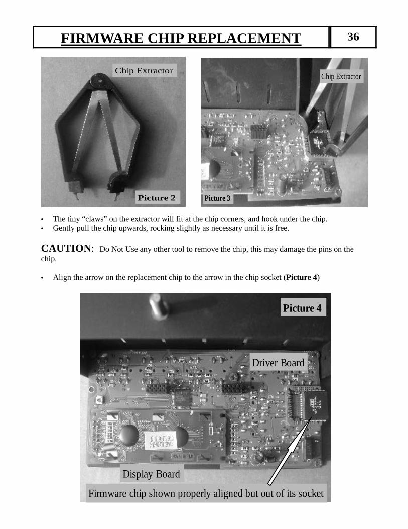
• The tiny “claws” on the extractor will fit at the chip corners, and hook under the chip. • Gently pull the chip upwards, rocking slightly as necessary until it is free.
CAUTION : Do Not Use any other tool to remove the chip, this may damage the pins on the chip. • Align the arrow on the replacement chip to the arrow in the chip socket (Picture 4)
Chip Extractor
Picture 2
Chip Extractor
Picture 3
Display Board
Driver Board
Firmware chip shown properly aligned but out of its socket
Picture 4
FIRMWARE CHIP REPLACEMENT 36
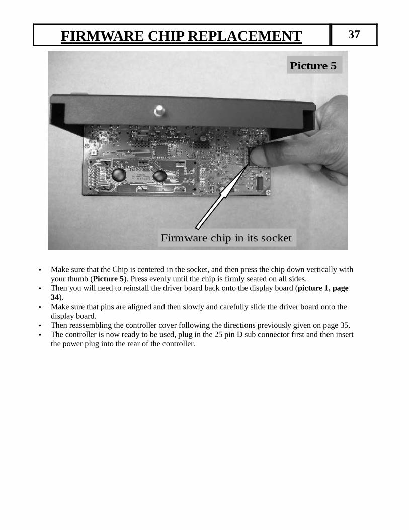
Picture 5
Firmware chip in its socket
• Make sure that the Chip is centered in the socket, and then press the chip down vertically with your thumb (Picture 5). Press evenly until the chip is firmly seated on all sides.
• Then you will need to reinstall the driver board back onto the display board (picture 1, page 34).
• Make sure that pins are aligned and then slowly and carefully slide the driver board onto the display board.
• Then reassembling the controller cover following the directions previously given on page 35. • The controller is now ready to be used, plug in the 25 pin D sub connector first and then insert
the power plug into the rear of the controller.
FIRMWARE CHIP REPLACEMENT 37

SteppIR Notes 38
SSST E P PT E P PT E P P I R ™ AI R ™ AI R ™ A N T E N N A SN T E N N A SN T E N N A S 39
L i m i t e d W a r r a n t y
These products have a limited warranty against manufacturer's defects in materials or construction for two (2) years from date of sale. Do not modify this product or change physical construction without the written permission of SteppIR Antennas Inc. This limited warranty is automatically void if the following occurs: improper installation, unauthorized modifications, physical abuse or damage from severe weather, beyond the manufacturer's control. Manufacturer's responsibility is strictly limited to repair, or replacement of defective components. The shipping instructions will be issued to the buyer for defective components, and shipping charges will be paid for by the buyer to the manufacturer. The manufacturer assumes no further liability.
www.steppir.com

Yagi � Dipole � Vertical www.steppir.com