
XLogic User's Manual2
339
U p d a t e d : F e b r u a r y 22 , 2 0 10 xLogic User's Manual Applied to ELC series CPU& Extensions __ Ver: 2.4
-
Upload
ivan-cruz-mamani -
Category
Documents
-
view
244 -
download
0
Transcript of XLogic User's Manual2

8/20/2019 XLogic User's Manual2
http://slidepdf.com/reader/full/xlogic-users-manual2 1/338
U p d a t e d : F e b r u a r y 22 , 2 0 10
xLogic User's Manual
Applied to ELC series CPU& Extensions __ Ver: 2.4

8/20/2019 XLogic User's Manual2
http://slidepdf.com/reader/full/xlogic-users-manual2 2/338
2
Contents
Introduction
Getting started
Installation and wiring
Programming xLogic
Configuring &software
Applications
Technical data
8/20/2019 XLogic User's Manual2
http://slidepdf.com/reader/full/xlogic-users-manual2 3/338
3
Introduction
Congratulations with your xLogic Micro PLC provided by Easy Electronic Co., Ltd.
The xLogic Micro PLC is a compact and expandable CPU replacing mini PLCs, multiple timers, relays and
counters.
The xLogic Micro PLC perfectly fits in the space between timing relays and low-end PLCs. Each CPU
incorporates not only a real-time clock and calendar, but also provides support for optional expansion I/O
modules to enhance control and monitoring applications. Data adjustments can easily be performed via
the keypad, the LCD display, or through the easy-to-use xLogic soft. DIN-rail and panel-mounted options
are both available, offering full flexibility to the various installation needs of your application.
The xLogic Micro PLC is available in 120V/240V AC or 12V and 24V DC versions, making it the ideal
solution for relay replacement, or simple control applications as building and parking lot lighting,
managing automatic lighting, access control, watering systems, pump control, ventilation systems,
home automation and a wide field of other applications demanding low cost to be a primary design issue.
We strongly recommended taking the time to read this manual, before putting the xLogic Micro PLC to
work. Installation, programming and use of the unit are detailed in this manual. The feature-rich xLogic
Micro PLC provides a for off-line operation mode, allowing full configuration and testing prior to in-field
service commissioning. In reviewing this manual you will discover many additional advantageous product
properties, it will greatly simplify and optimize the use of your xLogic Micro PLC.
Valid range of this manual
The manual applies to devices of ELC series modules . For more information about SMS module or
Ethernet module ,please refer to the SMS module or Ethernet module user's manual.

8/20/2019 XLogic User's Manual2
http://slidepdf.com/reader/full/xlogic-users-manual2 4/338
4
Safety Guideline
This manual contains notices you have to observe in order to ensure your personal safety, as well as to
prevent damage to property. The notices referring to your personal safety are highlighted in the manual
by a safety alert symbol; notices referring to property damage only have no safety alert symbol. The
notices shown below are graded according to the degree of danger.
Caution
Indicates that death or severe personal injury may result if proper precautions are
not taken
Caution
With a safety alert symbol indicates that minor personal injury can result if proper
precautions are not taken.
Caution
Without a safety alert symbol indicates that property damage can result if proper
precautions are not taken.
Attention
Indicate that an unintended result or situation can occur if the corresponding
notice is not taken into account.
If more than one degree of danger is present, the warning notice representing the highest degree of
danger will be used. A notice warning of injury to persons with a safety alert symbol may also include a
warning relating to property damage.
Qualified Personnel
The device/system may only be set up and used in conjunction with this documentation. Commissioning
and operation of a device/system may only be performed by qualified personnel. Within the context of
the safety notices in this documentation qualified persons are defined as persons who are authorized to
commission, ground and label devices, systems and circuits in accordance with established safety
practices and standards. Please read the complete operating instructions before installation and
commissioning.
EASY does not accept any liability for possible damage to persons, buildings or machines, which occur
due to incorrect use or from not following the details.
8/20/2019 XLogic User's Manual2
http://slidepdf.com/reader/full/xlogic-users-manual2 5/338
5
Prescribed Usage
Note the following:
Warning
This device and its components may only be used for the applications described in the catalog or the
technical description, and only in connection with devices or components from other manufacturers
which have been approved or recommended by EASY. Correct, reliable operation of the product requires
proper transport, storage, positioning and assembly as well as careful operation and maintenance.
Trademarks
All names identified by xLogic are registered trademarks of the EASY. The remaining trademarks in this
publication may be trademarks whose use by third parties for their own purposes could violate the rights
of the owner.
Copyright Easy 2007all rights reserved
The distribution and duplication of this document or the utilization and transmission of its contents are
not permitted without express written permission. Offenders will be liable for damages. All rights,
including rights created by patent grant or registration of a utility model or design, are reserved.
Disclaim of Liability
We have reviewed the contents of this publication to ensure consistency with the hardware and software
described. Since variance cannot be precluded entirely, we cannot guarantee full consistency. However,
the information in this publication is reviewed regularly and any necessary corrections are included in
subsequent editions.
Additional support
We take pride in answering your question as soon as we can:
Please consult our website at www.xLogic-plc.com for your closest point of contact or email us at
8/20/2019 XLogic User's Manual2
http://slidepdf.com/reader/full/xlogic-users-manual2 6/338
6
Contents
Contents.............................................................................................................................................................................................7
Chapter 1 General Introduction to xLogic.........................................................................................................................11
1.1 Overview................................................................................................................................................................................. 12
1.2 Highlight feature.................................................................................................................................................................. 12
Chapter 2 Hardware models and resources..................................................................................................................... 17
2.1 Naming Rules of ELC Series............................................................................................................................................17
2.2 Hardware model selection............................................................................................................................................... 18
2.3 Structure & dimension.......................................................................................................................................................24
Chapter 3 Installing/removing xLogic.................................................................................................................................27
3.1 DIN rail mounting................................................................................................................................................................27
3.2 Wall-mounting...................................................................................................................................................................... 29
3.3 Mounting ELC-HMI-FP........................................................................................................................................................32
3.4 wiring xLogic..........................................................................................................................................................................34
3.4.1 Connecting the power supply.............................................................................................................................34
3.4.2 Connecting xLogic inputs..................................................................................................................................... 35
3.4.3 Connecting xLogic Outputs..................................................................................................................................38
3.4.4 Communication port instructions:....................................................................................................................42
Chapter 4 Parameters modification HMI operation...................................................................................................45
4.1 Overview of xLogic menu.................................................................................................................................................
45
4.2 LCD panel instruction.........................................................................................................................................................45
4.3 Select function page...........................................................................................................................................................48
4.3.1 How to switch Run/Stop....................................................................................................................................... 50
4.3.2 Set parameter...........................................................................................................................................................51
4.3.3 Set password.............................................................................................................................................................54
4.3.4 How to set address of CPU and expansion module ...................................................................................57
4.3.5 Set LCD (backlight and Contrast).....................................................................................................................60
4.3.6 Set communication parameters........................................................................................................................ 61
4.3.7 Modification of System Time...............................................................................................................................63
Chapter 5 Programming via panel key............................................................................................................................... 65
5.1 Connectors............................................................................................................................................................................. 65
5.2 Blocks and block numbers............................................................................................................................................... 67
5.3 From circuit diagram to xLogic program................................................................................................................... 69
5.4 The four golden rules for operating xLogic...............................................................................................................71
5.5 Writing and starting the circuit program................................................................................................................... 72
5.5.1 Selecting programming mode............................................................................................................................72
5.5.2 The first circuit program.......................................................................................................................................73
5.5.3 Circuit program input............................................................................................................................................ 75
5.5.4 Assigning a circuit program name....................................................................................................................
78
5.5.5 Assigning system cover........................................................................................................................................ 79
8/20/2019 XLogic User's Manual2
http://slidepdf.com/reader/full/xlogic-users-manual2 7/338
7
5.5.6 Second circuit program.........................................................................................................................................80
5.5.7 Deleting a block....................................................................................................................................................... 85
5.6 Memory space and circuit program size.................................................................................................................... 86
Chapter 6 Configuring & Programming software........................................................................................................... 87
6.1 xLogic Functions...................................................................................................................................................................88
6.2 General Input & Output functions................................................................................................................................ 88
6.2.1 Inputs...........................................................................................................................................................................88
6.2.2 Cursor keys................................................................................................................................................................89
6.2.3 Outputs........................................................................................................................................................................89
6.2.4 Permanent logical levels HI and LO.................................................................................................................90
6.2.5 Panel Key.................................................................................................................................................................... 90
6.2.6 Shift register bits.....................................................................................................................................................91
6.2.7 Analog inputs............................................................................................................................................................ 91
6.2.8 F (digital flag)........................................................................................................................................................... 91
6.2.9 AF (Analog flag).......................................................................................................................................................
92
6.3 Basic functions list – GF....................................................................................................................................................93
6.3.1 AND............................................................................................................................................................................... 94
6.3.2 AND with edge evaluation................................................................................................................................... 95
6.3.3 NAND............................................................................................................................................................................ 95
6.3.4 NAND with edge evaluation................................................................................................................................ 96
6.3.5 OR..................................................................................................................................................................................97
6.3.6 NOR...............................................................................................................................................................................98
6.3.7 XOR............................................................................................................................................................................... 99
6.3.8 NOT............................................................................................................................................................................... 99
6.3.9 Boolean Function...................................................................................................................................................100
6.4 Basics on special functions........................................................................................................................................... 101
6.4.1 Designation of the inputs.................................................................................................................................. 101
6.4.2 Time response........................................................................................................................................................102
6.4.3 Backup of the real-time clock..........................................................................................................................103
6.4.4 Retentivity................................................................................................................................................................103
6.4.5 Parameter protection...........................................................................................................................................103
6.4.6 Calculating the gain and offset of analog values.....................................................................................103
6.5 Special functions list – SF............................................................................................................................................. 105
6.5.1 On-delay...................................................................................................................................................................
108
6.5.2 Off-delay...................................................................................................................................................................111
6.5.3 On-/Off-delay......................................................................................................................................................... 112
6.5.4 Retentive on-delay............................................................................................................................................... 114
6.5.5 Wiping relay (pulse output)..............................................................................................................................115
6.5.6 Edge triggered wiping relay............................................................................................................................. 116
6.5.7 Asynchronous pulse generator........................................................................................................................118
6.5.8 Random generator............................................................................................................................................... 120
6.5.9 Stairway lighting switch.....................................................................................................................................121
6.5.10 Multiple function switch................................................................................................................................... 123
6.5.11 Weekly timer........................................................................................................................................................125
8/20/2019 XLogic User's Manual2
http://slidepdf.com/reader/full/xlogic-users-manual2 8/338
8
6.5.12 Yearly timer.......................................................................................................................................................... 129
6.5.13 Up/Down counter............................................................................................................................................... 134
6.5.14 Hours counter...................................................................................................................................................... 136
6.5.15 Threshold trigger................................................................................................................................................139
6.5.16 Latching relay...................................................................................................................................................... 140
6.5.17 Pulse relay.............................................................................................................................................................141
6.5.18 Message text........................................................................................................................................................ 142
6.5.18.1 How to change parameters of blocks in displayed message ? ............................................150
6.5.19 Softkey................................................................................................................................................................... 152
6.5.20 Shift register........................................................................................................................................................ 154
6.5.21 Analog comparator............................................................................................................................................ 156
6.5.22 Analog threshold trigger..................................................................................................................................160
6.5.23 Analog amplifier..................................................................................................................................................163
6.5.25 Analog differential trigger...............................................................................................................................166
6.5.26 Analog multiplexer.............................................................................................................................................
169
6.5.27 System cover....................................................................................................................................................... 171
6.5.28 Pulse Width Modulator (PWM)...................................................................................................................... 173
6.5.29 Analog Ramp........................................................................................................................................................176
6.5.30 Analog Math..........................................................................................................................................................179
6.5.31 Analog math error detection......................................................................................................................... 181
6.5.32 Modbus Read........................................................................................................................................................183
6.5.33 Modbus Write....................................................................................................................................................... 189
6.5.34 Data latching relay............................................................................................................................................ 194
6.5.35 PI controller.......................................................................................................................................................... 196
6.5.36 Memory write.......................................................................................................................................................206
6.5.37 Memory Read....................................................................................................................................................... 212
6.5.38 Word to Bit............................................................................................................................................................216
6.5.39 Bit to Word............................................................................................................................................................217
6.5.40 Stopwatch..............................................................................................................................................................218
6.5.41 Analog filter.......................................................................................................................................................... 220
6.5.42 Max/Min..................................................................................................................................................................222
6.5.43 Average value...................................................................................................................................................... 225
6.5.44 Device Reset.........................................................................................................................................................227
6.5.45 Comport Status...................................................................................................................................................
230
6.5.46 Astronomical clock.............................................................................................................................................233
6.6 xLogicsoft............................................................................................................................................................................. 235
6.7 Main Functions................................................................................................................................................................... 241
6.8 Operation Instructions....................................................................................................................................................241
6.8.1 Menu Bar.................................................................................................................................................................. 242
6.8.1.1 File.................................................................................................................................................................. 242
6.8.1.2 Edit..................................................................................................................................................................243
6.8.1.3 Tools............................................................................................................................................................... 243
6.8.1.4 SMS................................................................................................................................................................ 244
6.8.1.5 View................................................................................................................................................................246
8/20/2019 XLogic User's Manual2
http://slidepdf.com/reader/full/xlogic-users-manual2 9/338
9
6.8.1.6 Help................................................................................................................................................................ 246
6.8.2 Toolbar.......................................................................................................................................................................247
6.8.3 Programming Toolbar..........................................................................................................................................247
6.8.4 Simulation Tool and status window...............................................................................................................249
6.9 Basic Operation..................................................................................................................................................................251
6.9.1 Open File.................................................................................................................................................................. 251
6.9.1.1 Open New File............................................................................................................................................ 251
6.9.1.2 Open Existed Document........................................................................................................................ 253
6.9.2 Edit Function Diagram Program......................................................................................................................254
6.9.2.1 Place Function Block................................................................................................................................254
6.9.2.2 Edit Property of Function Block...........................................................................................................254
6.9.2.3 Setup link.....................................................................................................................................................255
6.9.2.4 Delete Function Block or Delete Link ................................................................................................257
6.10 Simulation Running....................................................................................................................................................... 257
6.11 Save and Print.................................................................................................................................................................
259
6.12 Modify Password and transfer the Program.........................................................................................................260
6.13 On-line monitoring/test circuit program...............................................................................................................262
Chapter 7 How to configure the Ethernet modem built-in CPU ? ......................................................................... 267
7.1 Configuration with DeviceManager....................................................................................................................267
7.2 Establish communication between CPU and xLogicSoft/SCADA via Ethernet.................................276
7.3 How to establish the communication among CPUs via Ethernet ? .......................................................279
Chapter 8 Applications............................................................................................................................................................289
8.1 Dual-function switch........................................................................................................................................................290
8.2 Automatic gate...................................................................................................................................................................293
8.2.1 Standard solution..................................................................................................................................................294
8.2.2 The scheme of xLogic......................................................................................................................................... 295
8.3 Ventilation system............................................................................................................................................................ 296
8.3.1 Standard solution..................................................................................................................................................297
8.3.2 The scheme of xLogic......................................................................................................................................... 298
8.4 Factory door........................................................................................................................................................................ 300
8.4.1 Standard solution..................................................................................................................................................300
8.4.2 The scheme of xLogic......................................................................................................................................... 301
8.5 Daylight lamp system..................................................................................................................................................... 303
8.5.1 Standard solution..................................................................................................................................................
303
8.5.2 The scheme of xLogic......................................................................................................................................... 304
8.6 Rainwater pump................................................................................................................................................................ 305
8.6.1 Standard solution..................................................................................................................................................306
8.6.2 The scheme of xLogic......................................................................................................................................... 307
Chapter 9 Modbus function code and Register addresses....................................................................................... 308
9.2 Register addresses of xLogic........................................................................................................................................309
Appendix.......................................................................................................................................................................................316
A Technical data.........................................................................................................................................................................316
A.3 Switching capacity and service life of the relay outputs .................................................................................. 346
8/20/2019 XLogic User's Manual2
http://slidepdf.com/reader/full/xlogic-users-manual2 10/338
10
Chapter 1 General Introduction to xLogic
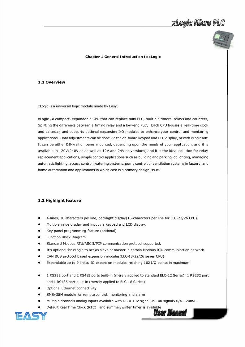
1.1 Overview
xLogic is a universal logic module made by Easy.
xLogic , a compact, expandable CPU that can replace mini PLC, multiple timers, relays and counters,
Splitting the difference between a timing relay and a low-end PLC, Each CPU houses a real-time clock
and calendar, and supports optional expansion I/O modules to enhance your control and monitoring
applications . Data adjustments can be done via the on-board keypad and LCD display, or with xLogicsoft.
It can be either DIN-rail or panel mounted, depending upon the needs of your application, and it is
available in 120V/240V ac as well as 12V and 24V dc versions, and it is the ideal solution for relay
replacement applications, simple control applications such as building and parking lot lighting, managing
automatic lighting, access control, watering systems, pump control, or ventilation systems in factory, and
home automation and applications in which cost is a primary design issue.
1.2 Highlight feature
4-lines, 10-characters per line, backlight display(16-characters per line for ELC-22/26 CPU).
Multiple value display and input via keypad and LCD display.
Key-panel programming feature (optional)
Function Block Diagram
Standard Modbus RTU/ASCII/TCP communication protocol supported.
It’s optional for xLogic to act as slave or master in certain Modbus RTU communication network.
CAN BUS protocol based expansion modules(ELC-18/22/26 series CPU)
Expandable up to 9 linked IO expansion modules reaching 162 I/O points in maximum
1 RS232 port and 2 RS485 ports built-in (merely applied to standard ELC-12 Series); 1 RS232 port
and 1 RS485 port built-in (merely applied to ELC-18 Series)
Optional Ethernet connectivity
SMS/GSM module for remote control, monitoring and alarm
Multiple channels analog inputs available with DC 0-10V signal ,PT100 signal& 0/4….20mA.
Default Real Time Clock (RTC) and summer/winter timer is available
8/20/2019 XLogic User's Manual2
http://slidepdf.com/reader/full/xlogic-users-manual2 11/338
11
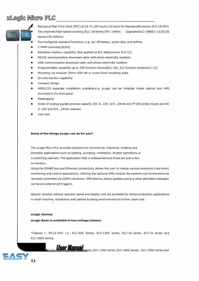
Backup at Real Time Clock (RTC) at 25 °C:100 hours (10 hours for Standard/Economic ELC-18 CPU)
Two channels high-speed counting (ELC-18 Series CPU :14KHz; Upgraded ELC-18&ELC-12/22/26
Series CPU:60KHz)
Pre-configured standard functions, e.g. on/ off-delays, pulse relay and softkey
2 PWM channels(333Hz)
Retentive memory capability (Not applied to ELC-6&economic ELC-12)
RS232 communication download cable with photo-electricity isolation
USB communication download cable with photo-electricity isolation
Programmable capability up to 256 function blocks(ELC-18) ,512 function blocks(ELC-12)
Mounting via modular 35mm DIN rail or screw fixed mounting plate
On-line monitor capability
Compact design
HMI(LCD) separate installation available,e.g. xLogic can be installed inside cabinet and HMI
mounted in it’s front panel
Datalogging
Kinds of analog signals process capacity (DC 0..10V ,0/4...20mA and PT100 probe inputs and DC
0..10V and 0/4...20mA outputs)
Low cost
Some of the things xLogic can do for you?
The xLogic Micro PLC provides solutions for commercial, industrial, building and
domestic applications such as lighting, pumping, ventilation, shutter operations or
in switching cabinets. The application field is widespread and these are just a few
to mention.
Using the RS485 bus and Ethernet connectivity allows the user to realize various extensive (real-time)
monitoring and control applications. Utilizing the optional SMS module the systems can furthermore be
remotely controlled via (GSM) cell phone. SMS Alarms, status updates and any other desirable messages
can be provided at set triggers.
Special versions without operator panel and display unit are available for series production applications
in small machine, installation and cabinet building environments to further slash cost.
xLogic devices:
xLogic Basic is available in two voltage classes:
*Classes 1: DC12-24V: i.e.: ELC-6DC Series, ELC-12DC series, ELC-18 series, ELC-22 series and
ELC-26DC Series.
*Classes2:AC110-240V: i.e.: ELC-6AC Series, ELC-12AC series, ELC-18AC series , ELC-22AC series and
8/20/2019 XLogic User's Manual2
http://slidepdf.com/reader/full/xlogic-users-manual2 12/338
12
ELC-26AC series
In the versions:
* With Display: ELC-18 Series (12 inputs and 6 outputs)
* Optional (With/without) Display: ELC-12 Series (8 inputs and 4 outputs),ELC-22 Series(14 inputs and
8 outputs), ELC-26 Series(16 inputs and 10 outputs)
ELC-18 Series is equipped with an expansion bus (Can Bus)
Each Version is provides 44 pre-configured standard and special function blocks for the creation of your
circuit program.
Expansion modules:
ELC-E (applied to ELC-18/22/26 CPU)
* xLogic digital modules are available for operation with 12…24V DC, and 110.. .240 V AC, and are
equipped with eight inputs and eight outputs.
* xLogic analog modules are available for operation with 12…24 V DC and are equipped with six digital
and two analog inputs.
ELC12-E(applied to ELC-12 CPU)
* xLogic digital modules are available for opera tion with 12…24V DC, and 110.. .240 V AC, and are
equipped with four inputs and four outputs.
* xLogic analog modules are available for operation with 12…24 V DC and are equipped with four
digital/analog inputs.
Communication modules:
xLogic:RS232 communication cable (Model:ELC-RS232)
It is kind of universal cable with photoelectricity isolation which can be directly connected to standard
9-pin port of PC, also kind of interface module which can enable user’s program to be downloaded into
xLogic CPU through xLogicsoft for running. It also is the connection cable between CPU and third party
device with the RS232 port(just like HMI) in modbus communication system.
xLogic: USB communication cable (Model: ELC-USB).
It is kind of communication cable with photoelectricity isolation through which PC with USB port only can
be connected to xLogic main module, moreover, it has same features as ELC-RS232 module, so it is
quite convenient for user whose computer has no standard serial port.
xLogic: Ethernet module
Model:
ELC-Ethernet
8/20/2019 XLogic User's Manual2
http://slidepdf.com/reader/full/xlogic-users-manual2 13/338
13
It is called Ethernet module, used to connect xLogic main modules in different places to enormous
Ethernet to buildup a huge monitoring and control system. It contains DC and AC two types.
xLogic:SMS module
Model:
ELC-SMS-D-R
ELC-SMS-D-R is kind of SMS module, through which SMS can be regarded as expansion input by user
to realize wireless remote control and it can send alarm messages to user cell phones.
Communication / Network
xLogic offers different ways to communicate within the system.
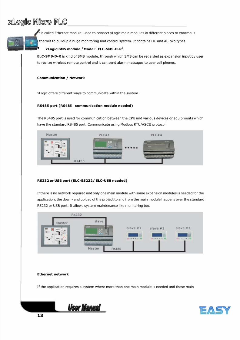
RS485 port (RS485 communication module needed)
The RS485 port is used for communication between the CPU and various devices or equipments which
have the standard RS485 port. Communicate using Modbus RTU/ASCII protocol.
RS232 or USB port (ELC-ES232/ ELC-USB needed)
If there is no network required and only one main module with some expansion modules is needed for the
application, the down- and upload of the project to and from the main module happens over the standard
RS232 or USB port. It allows system maintenance like monitoring too.
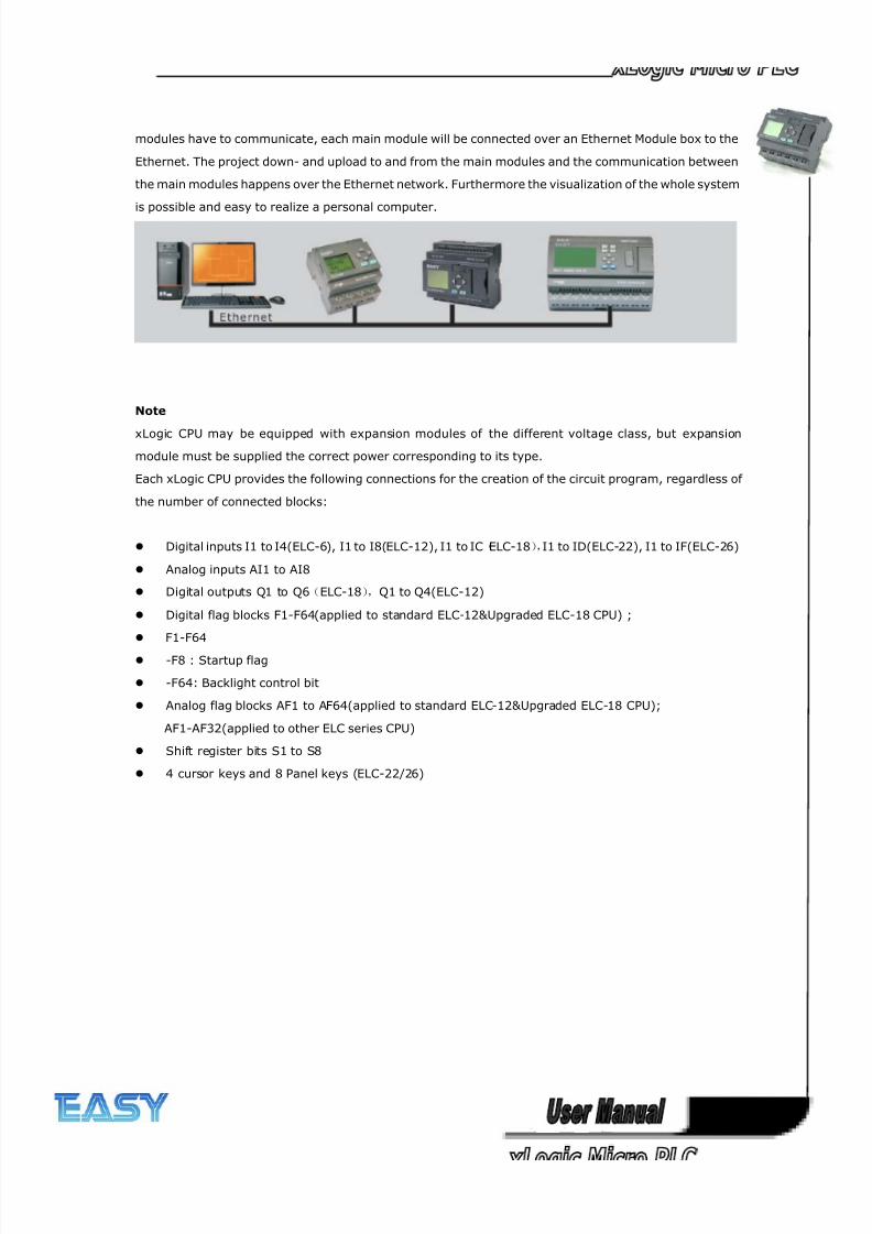
Ethernet network
If the application requires a system where more than one main module is needed and these main
8/20/2019 XLogic User's Manual2
http://slidepdf.com/reader/full/xlogic-users-manual2 14/338
14
modules have to communicate, each main module will be connected over an Ethernet Module box to the
Ethernet. The project down- and upload to and from the main modules and the communication between
the main modules happens over the Ethernet network. Furthermore the visualization of the whole system
is possible and easy to realize a personal computer.
Note
xLogic CPU may be equipped with expansion modules of the different voltage class, but expansion
module must be supplied the correct power corresponding to its type.
Each xLogic CPU provides the following connections for the creation of the circuit program, regardless of
the number of connected blocks:
Digital inputs I1 to I4(ELC-6), I1 to I8(ELC-12), I1 to IC(ELC-18),I1 to ID(ELC-22), I1 to IF(ELC-26)
Analog inputs AI1 to AI8
Digital outputs Q1 to Q6(ELC-18),Q1 to Q4(ELC-12)
Digital flag blocks F1-F64(applied to standard ELC-12&Upgraded ELC-18 CPU) ;
F1-F64
-F8 : Startup flag
-F64: Backlight control bit
Analog flag blocks AF1 to AF64(applied to standard ELC-12&Upgraded ELC-18 CPU);
AF1-AF32(applied to other ELC series CPU)
Shift register bits S1 to S8
4 cursor keys and 8 Panel keys (ELC-22/26)
8/20/2019 XLogic User's Manual2
http://slidepdf.com/reader/full/xlogic-users-manual2 15/338
15
Chapter 2 Hardware models and resources
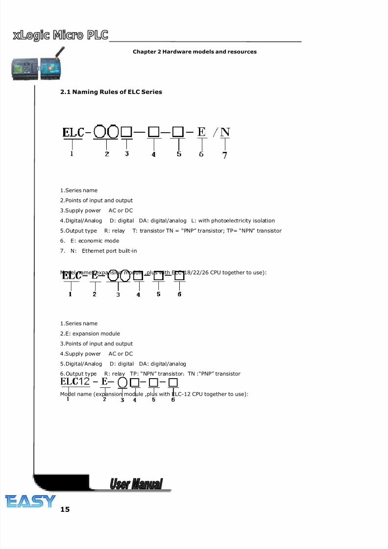
2.1 Naming Rules of ELC Series
1.Series name2.Points of input and output
3.Supply power AC or DC
4.Digital/Analog D: digital DA: digital/analog L: with photoelectricity isolation
5.Output type R: relay T: transistor TN = “PNP” transistor; TP= “NPN” transistor
6. E: economic mode
7. N: Ethernet port built-in
Model name (expansion module ,plus with ELC-18/22/26 CPU together to use):
1.Series name
2.E: expansion module
3.Points of input and output
4.Supply power AC or DC
5.Digital/Analog D: digital DA: digital/analog
6.Output type R: relay TP: “NPN” transistor;TN :“PNP” transistor
Model name (expansion module ,plus with ELC-12 CPU together to use):
8/20/2019 XLogic User's Manual2
http://slidepdf.com/reader/full/xlogic-users-manual2 16/338
16
1. Series name
2.E: expansion module
3.Points of input and output
4.Supply power AC or DC
5.Digital/Analog DA: digital/analog
6.Output type R: relay TP: “NPN” transistor;TN :“PNP” transistor
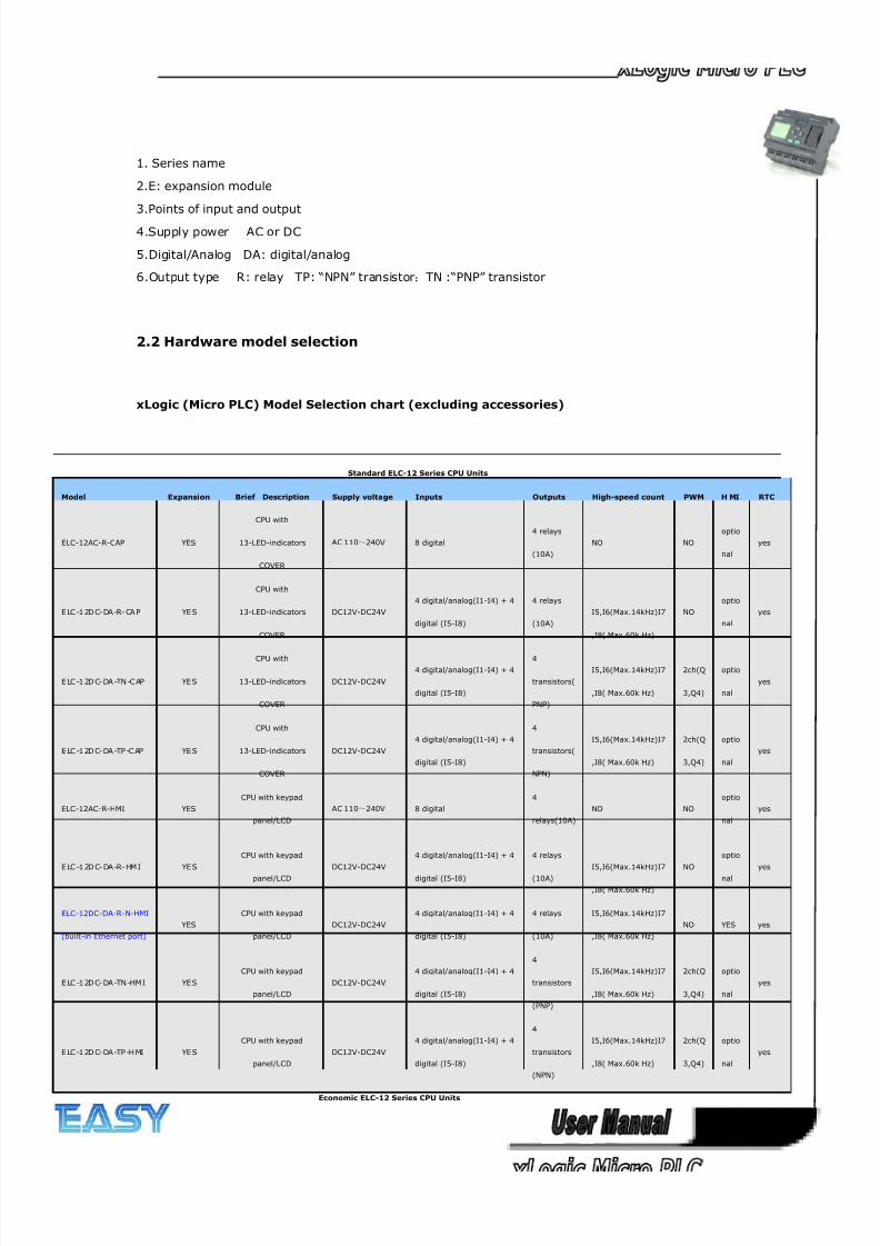
2.2 Hardware model selection
xLogic (Micro PLC) Model Selection chart (excluding accessories)
Standard ELC-12 Series CPU Units
Model Expansion Brief Description Supply voltage Inputs Outputs High-speed count PWM H MI RTC
ELC-12AC-R-CAP YES
CPU with
13-LED-indicators
COVER
AC 110~240V 8 digital
4 relays
(10A)
NO NO
optio
nal
yes
E LC -1 2D C- DA -R- CA P YE S
CPU with
13-LED-indicators
COVER
DC12V-DC24V
4 digital/analog(I1-I4) + 4
digital (I5-I8)
4 relays
(10A)
I5,I6(Max.14kHz)I7
,I8( Max.60k Hz)
NO
optio
nal
yes
E LC -1 2D C- DA -TN -C AP YE S
CPU with
13-LED-indicators
COVER
DC12V-DC24V
4 digital/analog(I1-I4) + 4
digital (I5-I8)
4
transistors(
PNP)
I5,I6(Max.14kHz)I7
,I8( Max.60k Hz)
2ch(Q
3,Q4)
optio
nal
yes
E LC -1 2D C- DA -TP -C AP YE S
CPU with
13-LED-indicators
COVER
DC12V-DC24V
4 digital/analog(I1-I4) + 4
digital (I5-I8)
4
transistors(
NPN)
I5,I6(Max.14kHz)I7
,I8( Max.60k Hz)
2ch(Q
3,Q4)
optio
nal
yes
ELC-12AC-R-HMI YES
CPU with keypad
panel/LCD
AC 110~240V 8 digital
4
relays(10A)
NO NO
optio
nal
yes
E LC -1 2D C- DA -R- HM I YE S
CPU with keypad
panel/LCD
DC12V-DC24V
4 digital/analog(I1-I4) + 4
digital (I5-I8)
4 relays
(10A)
I5,I6(Max.14kHz)I7
,I8( Max.60k Hz)
NO
optio
nal
yes
ELC-12DC-DA-R-N-HMI
(built-in Ethernet port)
YES
CPU with keypad
panel/LCD
DC12V-DC24V
4 digital/analog(I1-I4) + 4
digital (I5-I8)
4 relays
(10A)
I5,I6(Max.14kHz)I7
,I8( Max.60k Hz)
NO YES yes
E LC -1 2D C- DA -TN -HM I YE S
CPU with keypad
panel/LCD
DC12V-DC24V
4 digital/analog(I1-I4) + 4
digital (I5-I8)
4
transistors
(PNP)
I5,I6(Max.14kHz)I7
,I8( Max.60k Hz)
2ch(Q
3,Q4)
optio
nal
yes
E LC -1 2D C- DA -TP -H MI YE S
CPU with keypad
panel/LCD
DC12V-DC24V
4 digital/analog(I1-I4) + 4
digital (I5-I8)
4
transistors
(NPN)
I5,I6(Max.14kHz)I7
,I8( Max.60k Hz)
2ch(Q
3,Q4)
optio
nal
yes
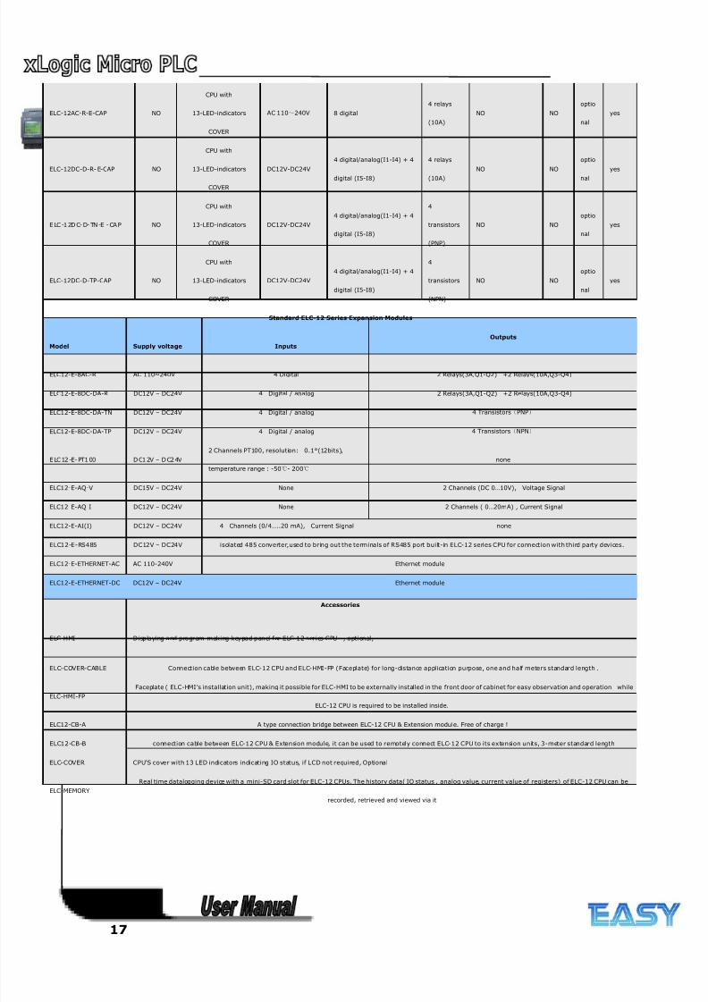
Economic ELC-12 Series CPU Units
8/20/2019 XLogic User's Manual2
http://slidepdf.com/reader/full/xlogic-users-manual2 17/338
17
ELC-12AC-R-E-CAP NO
CPU with
13-LED-indicators
COVER
AC 110~240V 8 digital
4 relays
(10A)
NO NO
optio
nal
yes
ELC-12DC-D-R- E-CAP NO
CPU with
13-LED-indicators
COVER
DC12V-DC24V
4 digital/analog(I1-I4) + 4
digital (I5-I8)
4 relays
(10A)
NO NO
optio
nal
yes
E LC -1 2D C- D- TN -E - CA P NO
CPU with
13-LED-indicators
COVER
DC12V-DC24V
4 digital/analog(I1-I4) + 4
digital (I5-I8)
4
transistors
(PNP)
NO NO
optio
nal
yes
ELC-12DC-D-TP-CAP NO
CPU with
13-LED-indicators
COVER
DC12V-DC24V
4 digital/analog(I1-I4) + 4
digital (I5-I8)
4
transistors
(NPN)
NO NO
optio
nal
yes
Standard ELC-12 Series Expansion Modules
Model Supply voltage Inputs
Outputs
ELC12-E-8AC-R AC 110~240V 4 Digital 2 Relays(3A,Q1-Q2) +2 Relays(10A,Q3-Q4)
ELC12-E-8DC-DA-R DC12V – DC24V 4 Digital / analog 2 Relays(3A,Q1-Q2) +2 Relays(10A,Q3-Q4)
ELC12-E-8DC-DA-TN DC12V – DC24V 4 Digital / analog 4 Transistors(PNP)
ELC12-E-8DC-DA-TP DC12V – DC24V 4 Digital / analog 4 Transistors(NPN)
E LC 12 -E- PT1 00 D C1 2V – D C2 4V
2 Channels PT100, resolution: 0.1°(12bits),
temperature range : -50℃- 200℃
none
ELC12-E-AQ-V DC15V – DC24V None 2 Channels (DC 0…10V), Voltage Signal
ELC12-E-AQ-I DC12V – DC24V None 2 Channels ( 0…20mA) , Current Signal
ELC12-E-AI(I) DC12V – DC24V 4 Channels (0/4…..20 mA), Current Signal none
ELC12-E-RS485 DC12V – DC24V isolated 485 converter,used to bring out the terminals of RS485 port built-in ELC-12 series CPU for connection with third party devices.
ELC12-E-ETHERNET-AC AC 110-240V Ethernet module
ELC12-E-ETHERNET-DC DC12V – DC24V Ethernet module
Accessories
ELC-HMI Displaying and program-making keypad panel for ELC-12 series CPU , optional,
ELC-COVER-CABLE Connection cable between ELC-12 CPU and ELC-HMI-FP (Faceplate) for long-distance application purpose, one and half meters standard length .
ELC-HMI-FP
Faceplate ( ELC-HMI’s installation unit), making it possible for ELC-HMI to be externally installed in the front door of cabinet for easy observation and operation while
ELC-12 CPU is required to be installed inside.
ELC12-CB-A A type connection bridge between ELC-12 CPU & Extension module. Free of charge !
ELC12-CB-B connection cable between ELC-12 CPU & Extension module, it can be used to remotely connect ELC-12 CPU to its extension units, 3-meter standard length
ELC-COVER CPU’S cover with 13 LED indicators indicating IO status, if LCD not required, Optional
ELC-MEMORY
Real time datalogging device with a mini-SD card slot for ELC-12 CPUs. The history data( IO status , analog value, current value of registers) of ELC-12 CPU can be
recorded, retrieved and viewed via it
8/20/2019 XLogic User's Manual2
http://slidepdf.com/reader/full/xlogic-users-manual2 18/338
18
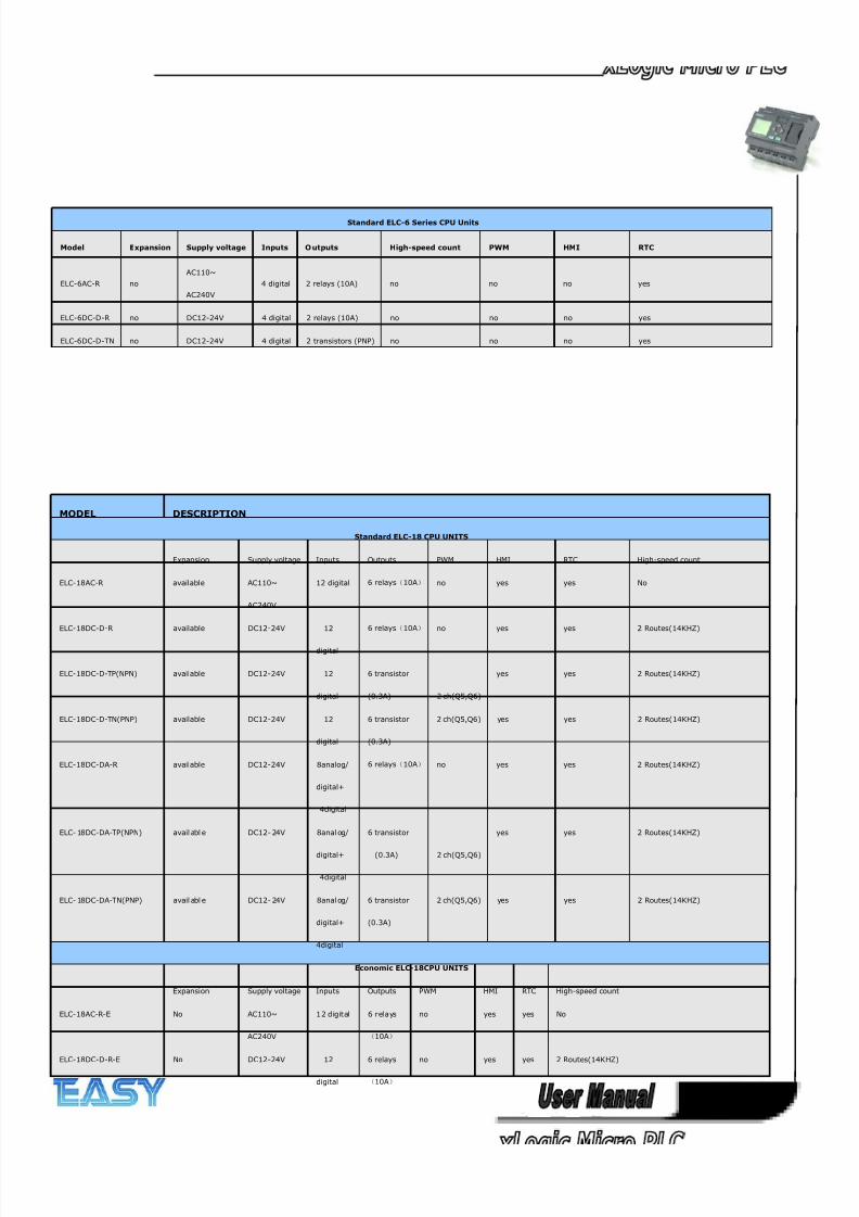
Standard ELC-6 Series CPU Units
Model Expansion Supply voltage Inputs O utputs High-speed count PWM HMI RTC
ELC-6AC-R no
AC110~
AC240V
4 digital 2 relays (10A) no no no yes
ELC-6DC-D-R no DC12-24V 4 digital 2 relays (10A) no no no yes
ELC-6DC-D-TN no DC12-24V 4 digital 2 transistors (PNP) no no no yes
MODEL DESCRIPTION
Standard ELC-18 CPU UNITS
Expansion Supply voltage Inputs Outputs PWM HMI RTC High-speed count
ELC-18AC-R available AC110~
AC240V
12 digital 6 relays(10A) no yes yes No
ELC-18DC-D-R available DC12-24V 12
digital
6 relays(10A) no yes yes 2 Routes(14KHZ)
ELC-18DC-D-TP(NPN) available DC12-24V 12
digital
6 transistor
(0.3A) 2 ch(Q5,Q6)
yes yes 2 Routes(14KHZ)
ELC-18DC-D-TN(PNP) available DC12-24V 12
digital
6 transistor
(0.3A)
2 ch(Q5,Q6) yes yes 2 Routes(14KHZ)
ELC-18DC-DA-R available DC12-24V 8analog/
digital+
4digital
6 relays(10A) no yes yes 2 Routes(14KHZ)
ELC- 18DC-DA-TP(NPN) avail abl e DC12- 24V 8anal og/
digital+
4digital
6 transistor
(0.3A) 2 ch(Q5,Q6)
yes yes 2 Routes(14KHZ)
ELC- 18DC-DA-TN(PNP) avail abl e DC12- 24V 8anal og/
digital+
4digital
6 transistor
(0.3A)
2 ch(Q5,Q6) yes yes 2 Routes(14KHZ)
Economic ELC-18CPU UNITS
Expansion Supply voltage Inputs Outputs PWM HMI RTC High-speed count
ELC-18AC-R-E No AC110~
AC240V
12 digital 6 relays
(10A)
no yes yes No
ELC-18DC-D-R-E No DC12-24V 12
digital
6 relays
(10A)
no yes yes 2 Routes(14KHZ)
8/20/2019 XLogic User's Manual2
http://slidepdf.com/reader/full/xlogic-users-manual2 19/338
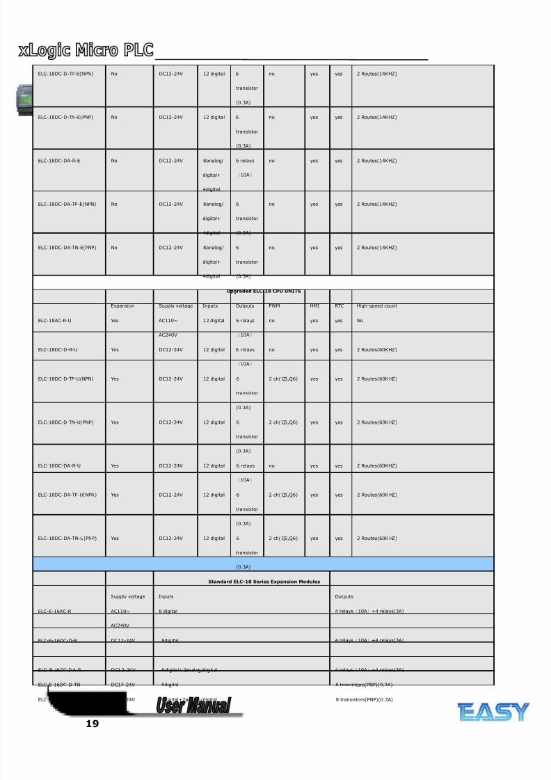
19
ELC-18DC-D-TP-E(NPN) No DC12-24V 12 digital 6
transistor
(0.3A)
no yes yes 2 Routes(14KHZ)
ELC-18DC-D-TN-E(PNP) No DC12-24V 12 digital 6
transistor
(0.3A)
no yes yes 2 Routes(14KHZ)
ELC-18DC-DA-R-E No DC12-24V 8analog/
digital+
4digital
6 relays
(10A)
no yes yes 2 Routes(14KHZ)
ELC-18DC-DA-TP-E(NPN) No DC12-24V 8analog/
digital+
4digital
6
transistor
(0.3A)
no yes yes 2 Routes(14KHZ)
ELC-18DC-DA-TN-E(PNP) No DC12-24V 8analog/
digital+
4digital
6
transistor
(0.3A)
no yes yes 2 Routes(14KHZ)
Upgraded ELC-18 CPU UNITS
Expansion Supply voltage Inputs Outputs PWM HMI RTC High-speed count
ELC-18AC-R-U Yes AC110~
AC240V
12 digital 6 relays
(10A)
no yes yes No
ELC-18DC-D-R-U Yes DC12-24V 12 digital 6 relays
(10A)
no yes yes 2 Routes(60KHZ)
ELC-18DC-D-TP-U(NPN) Yes DC12-24V 12 digital 6
transistor
(0.3A)
2 ch( Q5,Q6) yes yes 2 Routes(60K HZ)
ELC-18DC-D-TN-U(PNP) Yes DC12-24V 12 digital 6
transistor
(0.3A)
2 ch( Q5,Q6) yes yes 2 Routes(60K HZ)
ELC-18DC-DA-R-U Yes DC12-24V 12 digital 6 relays
(10A)
no yes yes 2 Routes(60KHZ)
ELC-18DC-DA-TP-U(NPN) Yes DC12-24V 12 digital 6
transistor
(0.3A)
2 ch( Q5,Q6) yes yes 2 Routes(60K HZ)
ELC-18DC-DA-TN-U(PNP) Yes DC12-24V 12 digital 6
transistor
(0.3A)
2 ch( Q5,Q6) yes yes 2 Routes(60K HZ)
Standard ELC-18 Series Expansion Modules
Supply voltage Inputs Outputs
ELC-E-16AC-R AC110~
AC240V
8 digital 4 relays(10A)+4 relays(3A)
ELC-E-16DC-D-R DC12-24V 8digital 4 relays(10A)+4 relays(3A)
E LC- E- 16 DC-D A- R D C1 2- 24 V 6 di gi ta l+ 2an al og /d ig it al 4 relays(10A)+4 relays(3A)
ELC-E-16DC-D-TN DC12-24V 8digital 8 transistors(PNP)(0.3A)
ELC-E-16DC-DA-TN DC12-24V 6digital+2analog/digital 8 transistors(PNP)(0.3A)
8/20/2019 XLogic User's Manual2
http://slidepdf.com/reader/full/xlogic-users-manual2 20/338
20
ELC-E-PT100 DC12-24V 3 Channels PT100, resolution: 0.1°(12bits), temperature range : -50℃-
200℃
none
ELC-E-AQ-V DC15V – DC24V none 2 Channels (DC 0…10V), Voltage Signal
ELC-E-AQ-I DC12-24V none 2 Channels (0/4…..20 mA), Current Signal
ELC-E-AI(I) DC12-24V 4 Channels (0/4…..20 mA), Current Signal none
ELC-RS485 DC12-24V isolated 485 converter,used to bring out the terminals of RS485 port built-in ELC-12 series CPU for connection with third party devices.
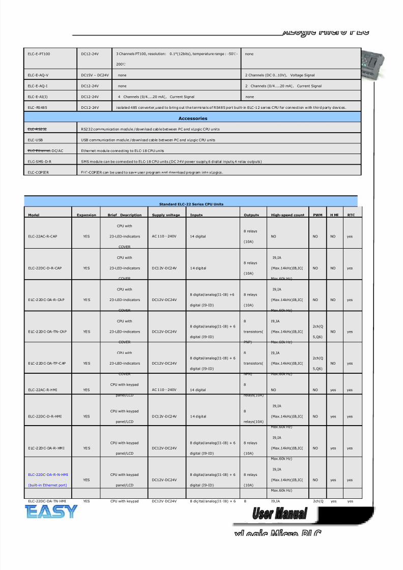
Accessories
ELC-RS232 RS232 communication module /download cable between PC and xLogic CPU units
ELC-USB USB communication module /download cable between PC and xLogic CPU units
ELC-Ethernet-DC/AC Ethernet module connecting to ELC-18 CPU units
ELC-SMS-D-R SMS module can be connected to ELC-18 CPU units.(DC 24V power supply,6 digital inputs,4 relay outputs)
ELC-COPIER ELC-COPIER can be used to save user program and download program into xLogics.
Standard ELC-22 Series CPU Units
Model Expansion Brief Description Supply voltage Inputs Outputs High-speed count PWM H MI RTC
ELC-22AC-R-CAP YES
CPU with
23-LED-indicators
COVER
AC 110~240V 14 digital
8 relays
(10A)
NO NO NO yes
ELC-22DC-D-R-CAP YES
CPU with
23-LED-indicators
COVER
DC12V -DC24V 14 d ig it al
8 relays
(10A)
I9,IA
(Max.14kHz)IB,IC(
Max.60k Hz)
NO NO yes
E LC -2 2D C- DA -R- CA P YE S
CPU with
23-LED-indicators
COVER
DC12V-DC24V
8 digital/analog(I1-I8) +6
digital (I9-ID)
8 relays
(10A)
I9,IA
(Max.14kHz)IB,IC(
Max.60k Hz)
NO NO yes
E LC -2 2D C- DA -TN- CA P YE S
CPU with
23-LED-indicators
COVER
DC12V-DC24V
8 digital/analog(I1-I8) + 6
digital (I9-ID)
8
transistors(
PNP)
I9,IA
(Max.14kHz)IB,IC(
Max.60k Hz)
2ch(Q
5,Q6)
NO yes
E LC -2 2D C- DA -TP -C AP YE S
CPU with
23-LED-indicators
COVER
DC12V-DC24V
8 digital/analog(I1-I8) + 6
digital (I9-ID)
8
transistors(
NPN)
I9,IA
(Max.14kHz)IB,IC(
Max.60k Hz)
2ch(Q
5,Q6)
NO yes
ELC-22AC-R-HMI YES
CPU with keypad
panel/LCD
AC 110~240V 14 digital
8
relays(10A)
NO NO yes yes
ELC-22DC-D-R-HMI YES
CPU with keypad
panel/LCD
DC12V -DC24V 14 d ig it al
8
relays(10A)
I9,IA
(Max.14kHz)IB,IC(
Max.60k Hz)
NO yes yes
E LC -2 2D C- DA -R- HM I YE S
CPU with keypad
panel/LCD
DC12V-DC24V
8 digital/analog(I1-I8) + 6
digital (I9-ID)
8 relays
(10A)
I9,IA
(Max.14kHz)IB,IC(
Max.60k Hz)
NO yes yes
ELC-22DC-DA-R-N-HMI
(built-in Ethernet port)
YES
CPU with keypad
panel/LCD
DC12V-DC24V
8 digital/analog(I1-I8) + 6
digital (I9-ID)
8 relays
(10A)
I9,IA
(Max.14kHz)IB,IC(
Max.60k Hz)
NO yes yes
ELC-22DC-DA-TN-HMI YES CPU with keypad DC12V-DC24V 8 digital/analog(I1-I8) + 6 8 I9,IA 2ch(Q yes yes
8/20/2019 XLogic User's Manual2
http://slidepdf.com/reader/full/xlogic-users-manual2 21/338
21
panel/LCD digital (I9-ID) transistors
(PNP)
(Max.14kHz)IB,IC(
Max.60k Hz)
5,Q6)
E LC -2 2D C- DA -TP -H MI YE S
CPU with keypad
panel/LCD
DC12V-DC24V
8 digital/analog(I1-I8) + 6
digital (I9-ID)
8
transistors
(NPN)
I9,IA
(Max.14kHz)IB,IC(
Max.60k Hz)
2ch(Q
5,Q6)
yes yes
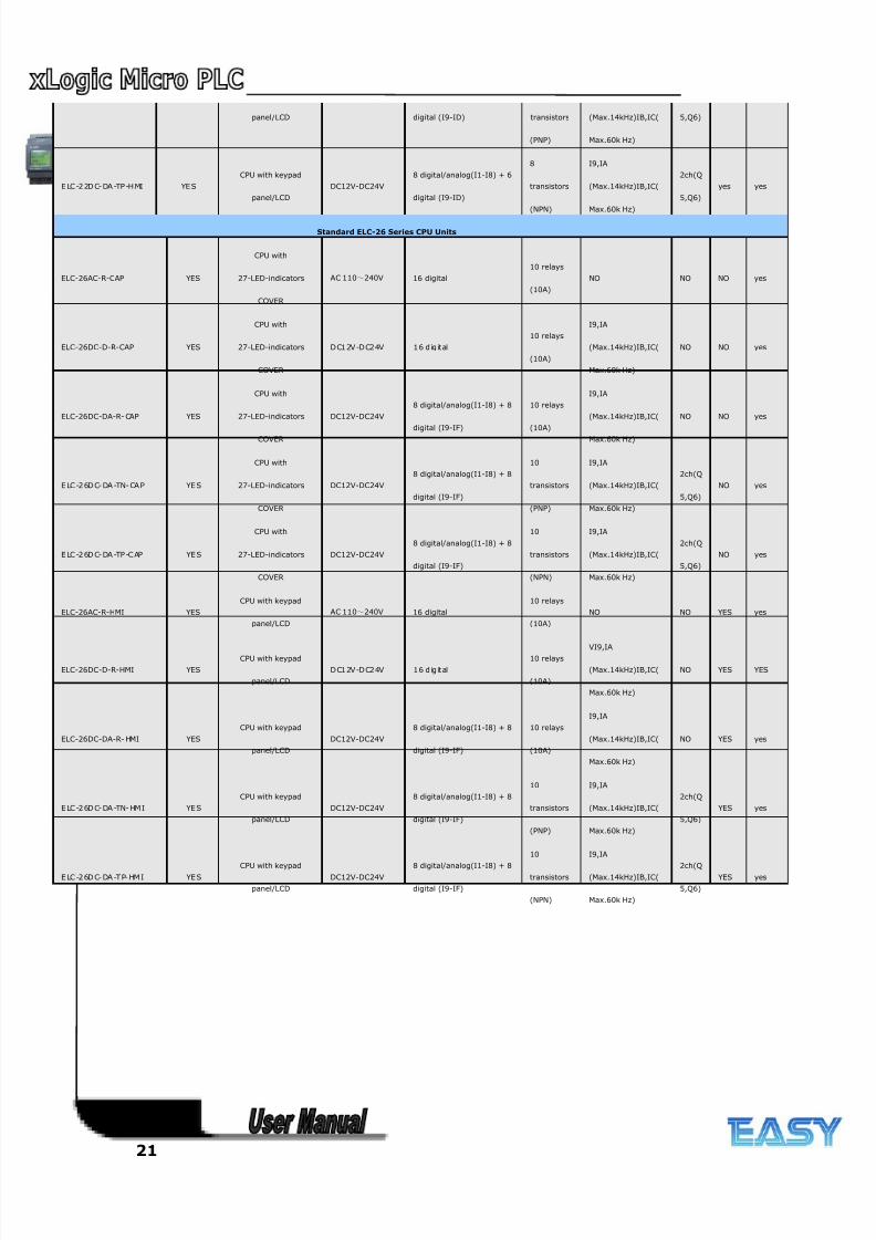
Standard ELC-26 Series CPU Units
ELC-26AC-R-CAP YES
CPU with
27-LED-indicators
COVER
AC 110~240V 16 digital
10 relays
(10A)
NO NO NO yes
ELC-26DC-D-R-CAP YES
CPU with
27-LED-indicators
COVER
DC12V -DC24V 16 d ig it al
10 relays
(10A)
I9,IA
(Max.14kHz)IB,IC(
Max.60k Hz)
NO NO yes
ELC-26DC-DA-R- CAP YES
CPU with
27-LED-indicators
COVER
DC12V-DC24V
8 digital/analog(I1-I8) + 8
digital (I9-IF)
10 relays
(10A)
I9,IA
(Max.14kHz)IB,IC(
Max.60k Hz)
NO NO yes
E LC -2 6D C- DA -TN- CA P YE S
CPU with
27-LED-indicators
COVER
DC12V-DC24V
8 digital/analog(I1-I8) + 8
digital (I9-IF)
10
transistors
(PNP)
I9,IA
(Max.14kHz)IB,IC(
Max.60k Hz)
2ch(Q
5,Q6)
NO yes
E LC -2 6D C- DA -TP -C AP YE S
CPU with
27-LED-indicators
COVER
DC12V-DC24V
8 digital/analog(I1-I8) + 8
digital (I9-IF)
10
transistors
(NPN)
I9,IA
(Max.14kHz)IB,IC(
Max.60k Hz)
2ch(Q
5,Q6)
NO yes
ELC-26AC-R-HMI YES
CPU with keypad
panel/LCD
AC 110~240V 16 digital
10 relays
(10A)
NO NO YES yes
ELC-26DC-D-R-HMI YES
CPU with keypad
panel/LCD
DC12V -DC24V 16 d ig it al
10 relays
(10A)
VI9,IA
(Max.14kHz)IB,IC(
Max.60k Hz)
NO YES YES
ELC-26DC-DA-R- HMI YES
CPU with keypad
panel/LCD
DC12V-DC24V
8 digital/analog(I1-I8) + 8
digital (I9-IF)
10 relays
(10A)
I9,IA
(Max.14kHz)IB,IC(
Max.60k Hz)
NO YES yes
E LC -2 6D C- DA -TN- HM I YE S
CPU with keypad
panel/LCD
DC12V-DC24V
8 digital/analog(I1-I8) + 8
digital (I9-IF)
10
transistors
(PNP)
I9,IA
(Max.14kHz)IB,IC(
Max.60k Hz)
2ch(Q
5,Q6)
YES yes
E LC -2 6D C- DA -T P- HM I YE SCPU with keypad
panel/LCD
DC12V-DC24V8 digital/analog(I1-I8) + 8
digital (I9-IF)
10
transistors
(NPN)
I9,IA
(Max.14kHz)IB,IC(
Max.60k Hz)
2ch(Q
5,Q6)
YES yes
8/20/2019 XLogic User's Manual2
http://slidepdf.com/reader/full/xlogic-users-manual2 22/338
22
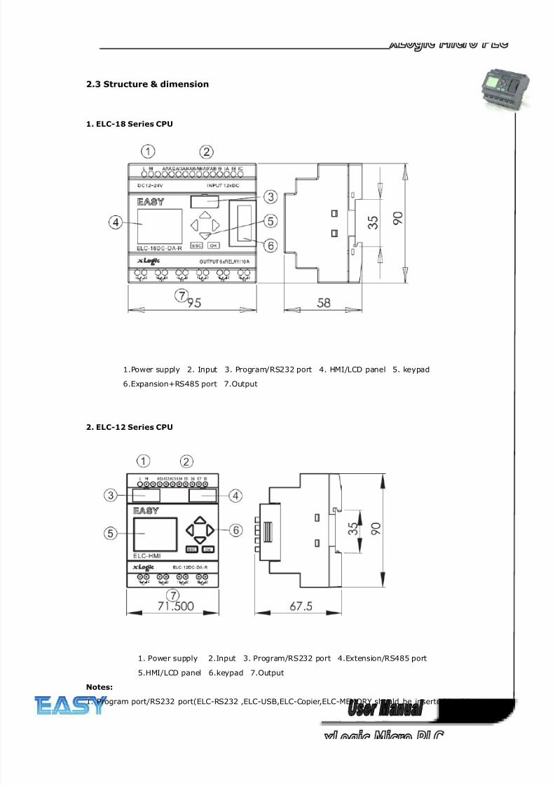
2.3 Structure & dimension
1. ELC-18 Series CPU
1.Power supply 2. Input 3. Program/RS232 port 4. HMI/LCD panel 5. keypad
6.Expansion+RS485 port 7.Output
2. ELC-12 Series CPU
1. Power supply 2.Input 3. Program/RS232 port 4.Extension/RS485 port
5.HMI/LCD panel 6.keypad 7.Output
Notes:
1. Program port/RS232 port(ELC-RS232 ,ELC-USB,ELC-Copier,ELC-MEMORY should be inserted in this
8/20/2019 XLogic User's Manual2
http://slidepdf.com/reader/full/xlogic-users-manual2 23/338
23
port)
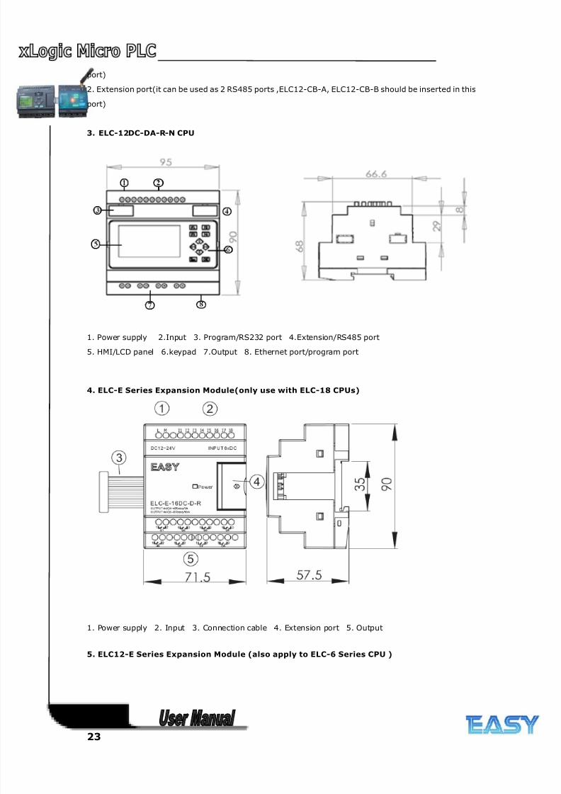
2. Extension port(it can be used as 2 RS485 ports ,ELC12-CB-A, ELC12-CB-B should be inserted in this
port)
3. ELC-12DC-DA-R-N CPU
1. Power supply 2.Input 3. Program/RS232 port 4.Extension/RS485 port
5. HMI/LCD panel 6.keypad 7.Output 8. Ethernet port/program port
4. ELC-E Series Expansion Module(only use with ELC-18 CPUs)
1. Power supply 2. Input 3. Connection cable 4. Extension port 5. Output
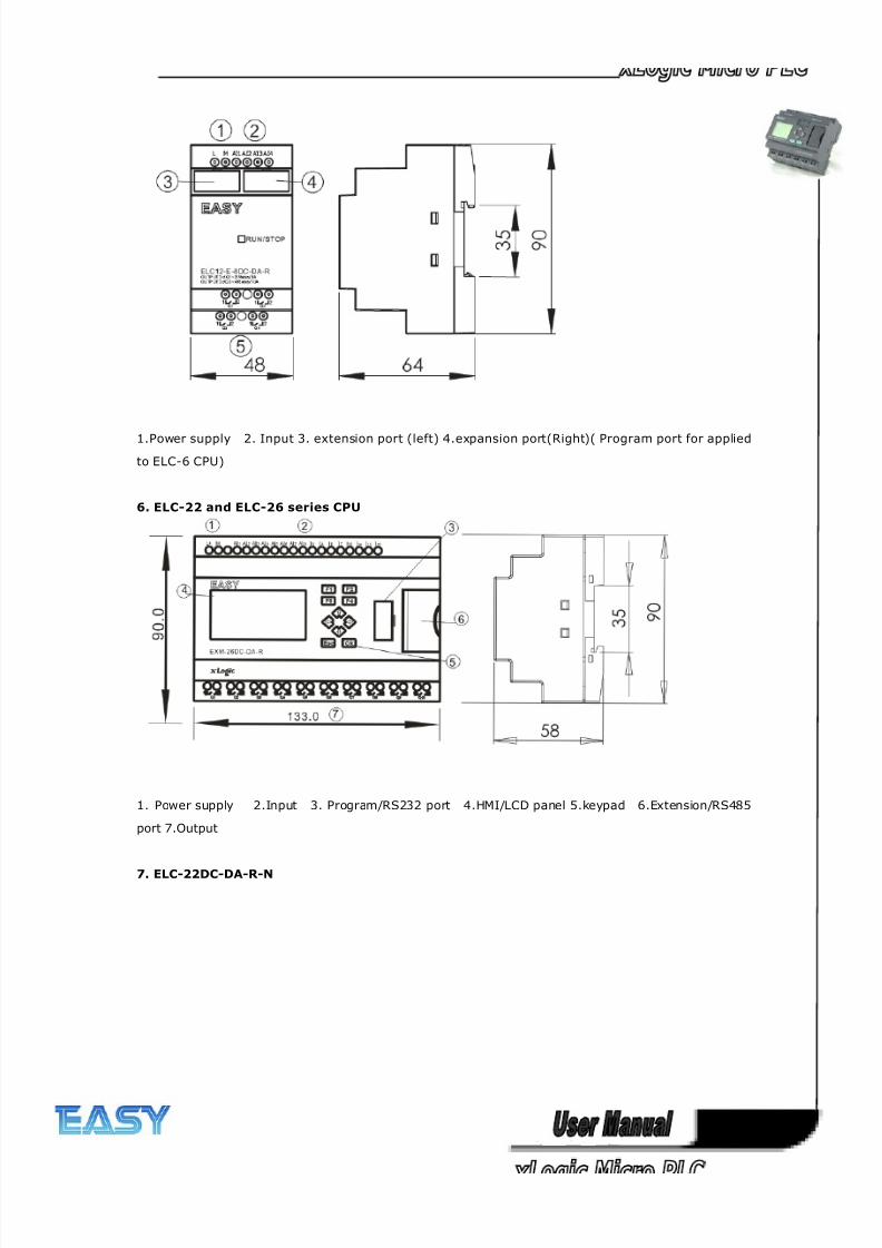
5. ELC12-E Series Expansion Module (also apply to ELC-6 Series CPU )
8/20/2019 XLogic User's Manual2
http://slidepdf.com/reader/full/xlogic-users-manual2 24/338
24
1.Power supply 2. Input 3. extension port (left) 4.expansion port(Right)( Program port for applied
to ELC-6 CPU)
6. ELC-22 and ELC-26 series CPU
1. Power supply 2.Input 3. Program/RS232 port 4.HMI/LCD panel 5.keypad 6.Extension/RS485
port 7.Output
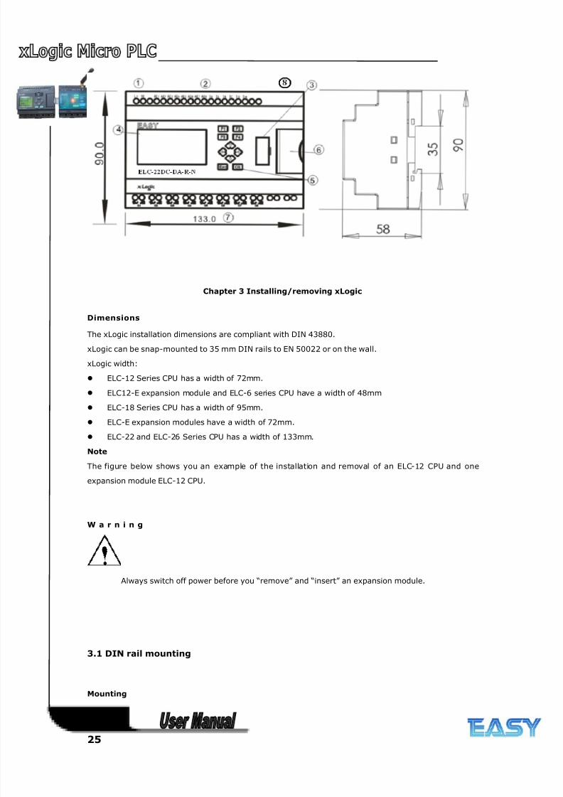
7. ELC-22DC-DA-R-N
8/20/2019 XLogic User's Manual2
http://slidepdf.com/reader/full/xlogic-users-manual2 25/338
25
Chapter 3 Installing/removing xLogic
Dimensions
The xLogic installation dimensions are compliant with DIN 43880.
xLogic can be snap-mounted to 35 mm DIN rails to EN 50022 or on the wall.
xLogic width:
ELC-12 Series CPU has a width of 72mm.
ELC12-E expansion module and ELC-6 series CPU have a width of 48mm
ELC-18 Series CPU has a width of 95mm.
ELC-E expansion modules have a width of 72mm.
ELC-22 and ELC-26 Series CPU has a width of 133mm.
Note
The figure below shows you an example of the installation and removal of an ELC-12 CPU and one
expansion module ELC-12 CPU.
W a r n i n g
Always switch off power before you “remove” and “insert” an expansion module.
3.1 DIN rail mounting
Mounting

8/20/2019 XLogic User's Manual2
http://slidepdf.com/reader/full/xlogic-users-manual2 26/338
26
How to mount a xLogic module and a expansion module onto a DIN rail:
1. Hook the xLogic Basic module onto the rail.
2. Push down the lower end to snap it on. The mounting interlock at the rear must engage.
3. Hook the xLogic expansion module onto the rail
4. Slide the module towards the left until it touches the xLogic CPU.
5. Push down the lower end to snap it on. The mounting interlock at the rear must engage.
6. Remove the plastic cover in the expansion port of CPU and expansion module.
7. Plus the connection bridge
Repeat the expansion module steps to mount further expansion modules.
Notes: 1. ELC12-E extensions connect with ELC-12 CPU by ELC12-CB-A bridge or ELC12-CB-B
connection cable (3 meters)
2. ELC-E extensions connect with ELC-18 ,ELC-22 or ELC-26 CPU directly by the
connector with flat cable of the expansion module
Removal
To remove xLogic:
....... if you have installed only one xLogic Basic:
8/20/2019 XLogic User's Manual2
http://slidepdf.com/reader/full/xlogic-users-manual2 27/338
27
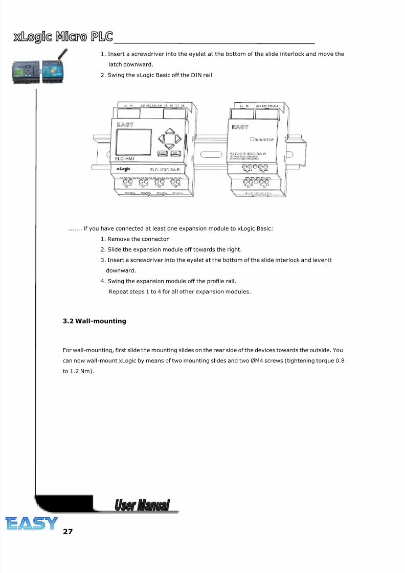
1. Insert a screwdriver into the eyelet at the bottom of the slide interlock and move the
latch downward.
2. Swing the xLogic Basic off the DIN rail.
....... if you have connected at least one expansion module to xLogic Basic:
1. Remove the connector
2. Slide the expansion module off towards the right.
3. Insert a screwdriver into the eyelet at the bottom of the slide interlock and lever it
downward.
4. Swing the expansion module off the profile rail.
Repeat steps 1 to 4 for all other expansion modules.
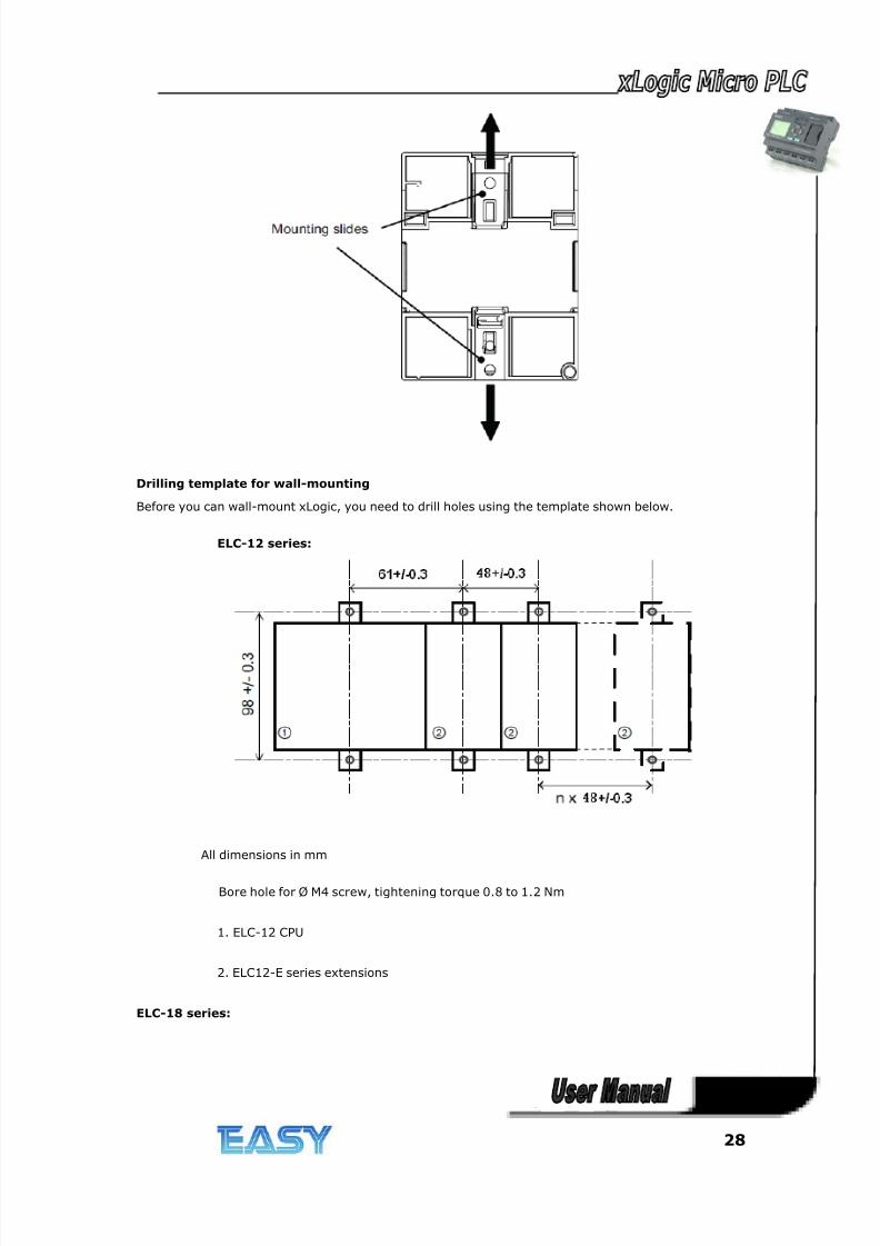
3.2 Wall-mounting
For wall-mounting, first slide the mounting slides on the rear side of the devices towards the outside. You
can now wall-mount xLogic by means of two mounting slides and two ØM4 screws (tightening torque 0.8
to 1.2 Nm).
8/20/2019 XLogic User's Manual2
http://slidepdf.com/reader/full/xlogic-users-manual2 28/338
28
Drilling template for wall-mounting
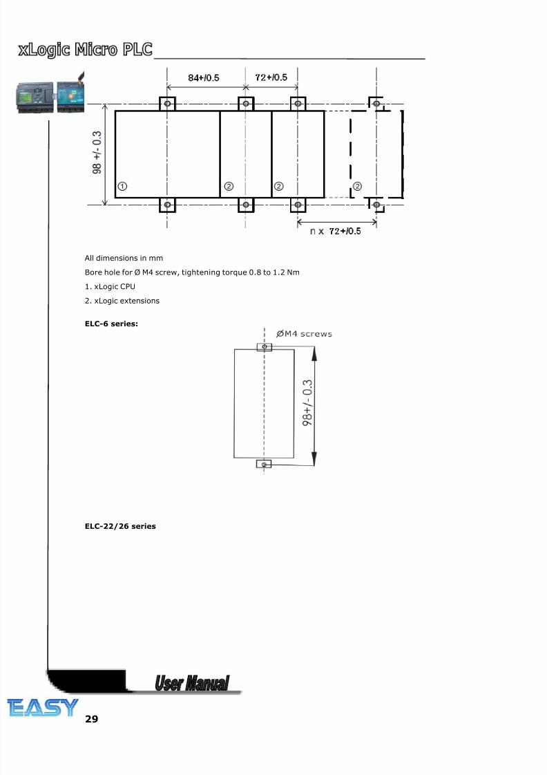
Before you can wall-mount xLogic, you need to drill holes using the template shown below.
ELC-12 series:
All dimensions in mm
Bore hole for Ø M4 screw, tightening torque 0.8 to 1.2 Nm
1. ELC-12 CPU
2. ELC12-E series extensions
ELC-18 series:
8/20/2019 XLogic User's Manual2
http://slidepdf.com/reader/full/xlogic-users-manual2 29/338
29
All dimensions in mm
Bore hole for Ø M4 screw, tightening torque 0.8 to 1.2 Nm
1. xLogic CPU
2. xLogic extensions
ELC-6 series:
ELC-22/26 series
8/20/2019 XLogic User's Manual2
http://slidepdf.com/reader/full/xlogic-users-manual2 30/338
30
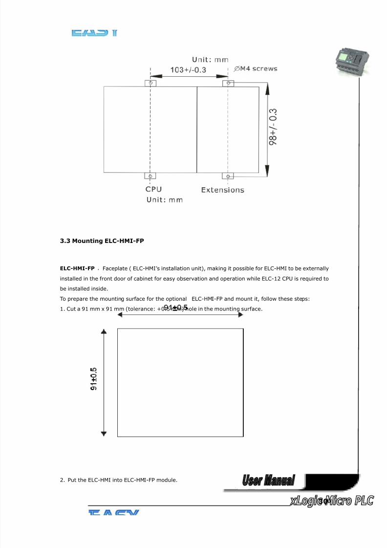
3.3 Mounting ELC-HMI-FP
ELC-HMI-FP ,Faceplate ( ELC-HMI’s installation unit), making it possible for ELC-HMI to be externally
installed in the front door of cabinet for easy observation and operation while ELC-12 CPU is required to
be installed inside.
To prepare the mounting surface for the optional ELC-HMI-FP and mount it, follow these steps:
1. Cut a 91 mm x 91 mm (tolerance: +0.5 mm) hole in the mounting surface.
2. Put the ELC-HMI into ELC-HMI-FP module.
8/20/2019 XLogic User's Manual2
http://slidepdf.com/reader/full/xlogic-users-manual2 31/338
31
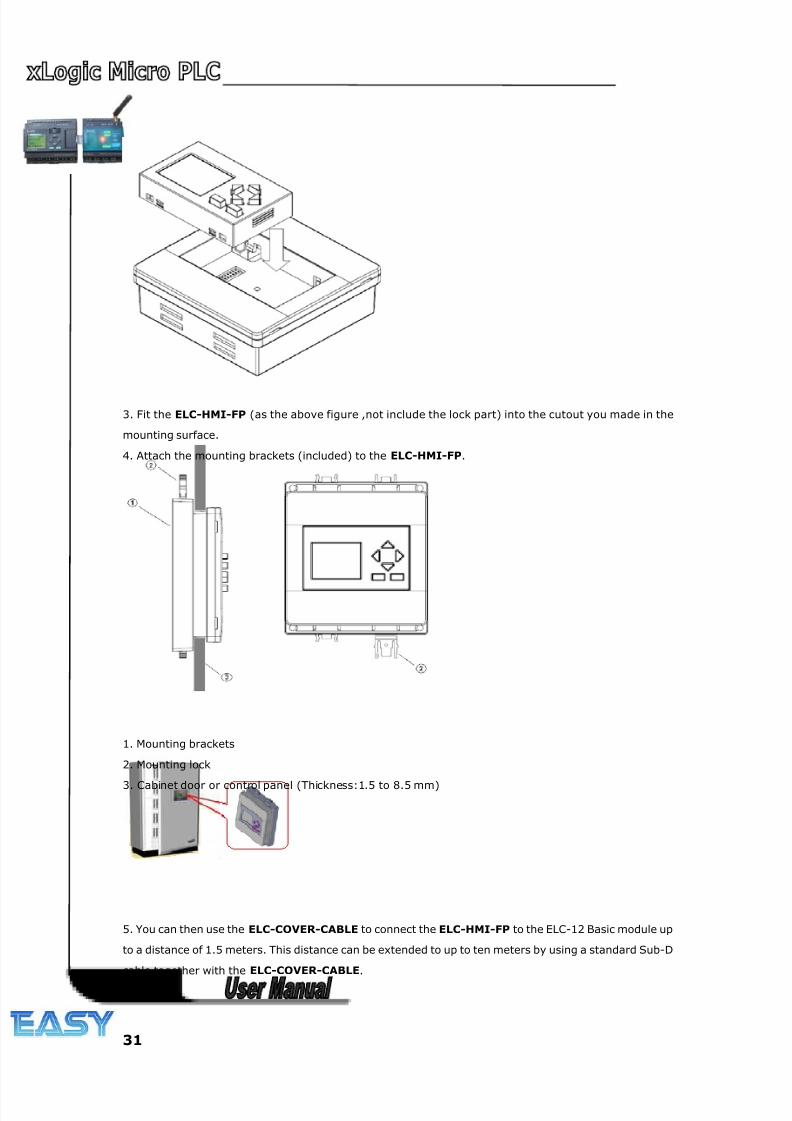
3. Fit the ELC-HMI-FP (as the above figure ,not include the lock part) into the cutout you made in the
mounting surface.
4. Attach the mounting brackets (included) to the ELC-HMI-FP.
1. Mounting brackets
2. Mounting lock
3. Cabinet door or control panel (Thickness:1.5 to 8.5 mm)
5. You can then use the ELC-COVER-CABLE to connect the ELC-HMI-FP to the ELC-12 Basic module up
to a distance of 1.5 meters. This distance can be extended to up to ten meters by using a standard Sub-D
cable together with the ELC-COVER-CABLE.
8/20/2019 XLogic User's Manual2
http://slidepdf.com/reader/full/xlogic-users-manual2 32/338
32
3.4 wiring xLogic
Wire the xLogic using a screwdriver with a 3-mm blade.
You do not need wire ferrules for the terminals. You can use conductors with
cross-sections of up to the following thicknesses:
1 x 2.5 mm2
2 x 1.5 mm2 for each second terminal chamber
Tightening torque: 0.4.. .0.5 N/m or 3. ..4 lbs/in
Note
Always cover the terminals after you have completed the in st al la ti o n. To pr ot ec t
xL o g i c ad eq u a t e l y fr o m impermissible contact to live parts, local standards must
be complied with.
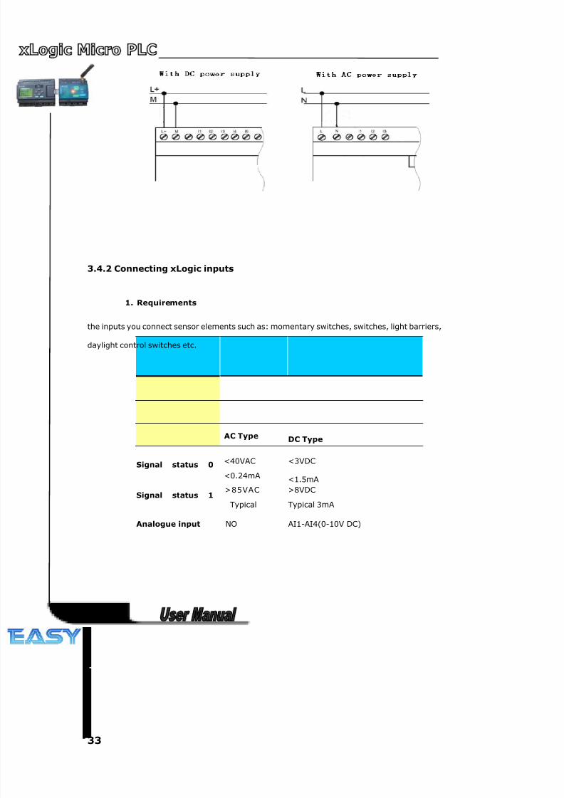
3.4.1 Connecting the power supply
The ELC-6AC, ELC-12AC,ELC-18AC, ELC-22AC and ELC-26AC versions of xLogic
are suitable for operation with rated voltages of 110 V AC and 240 V AC. The ELC-6DC,
ELC-12DC,ELC-18DC, ELC-22DC and ELC-26DC versions can be operated with a
12 or 24 VDC power supply.
Note
A power failure may cause an additional edge triggering signal.
Data of the last uninterrupted cycle are stored in xLogic
To connect xLogic to the power supply:
8/20/2019 XLogic User's Manual2
http://slidepdf.com/reader/full/xlogic-users-manual2 33/338
33
3.4.2 Connecting xLogic inputs
1. Requirements
the inputs you connect sensor elements such as: momentary switches, switches, light barriers,
daylight control switches etc.
AC Type DC Type
Signal status 0 <40VAC
<0.24mA
<3VDC
<1.5mA
Signal status 1 >85VAC
Typical
>8VDC
Typical 3mA
Analogue input NO AI1-AI4(0-10V DC)
8/20/2019 XLogic User's Manual2
http://slidepdf.com/reader/full/xlogic-users-manual2 34/338
34
At
2.
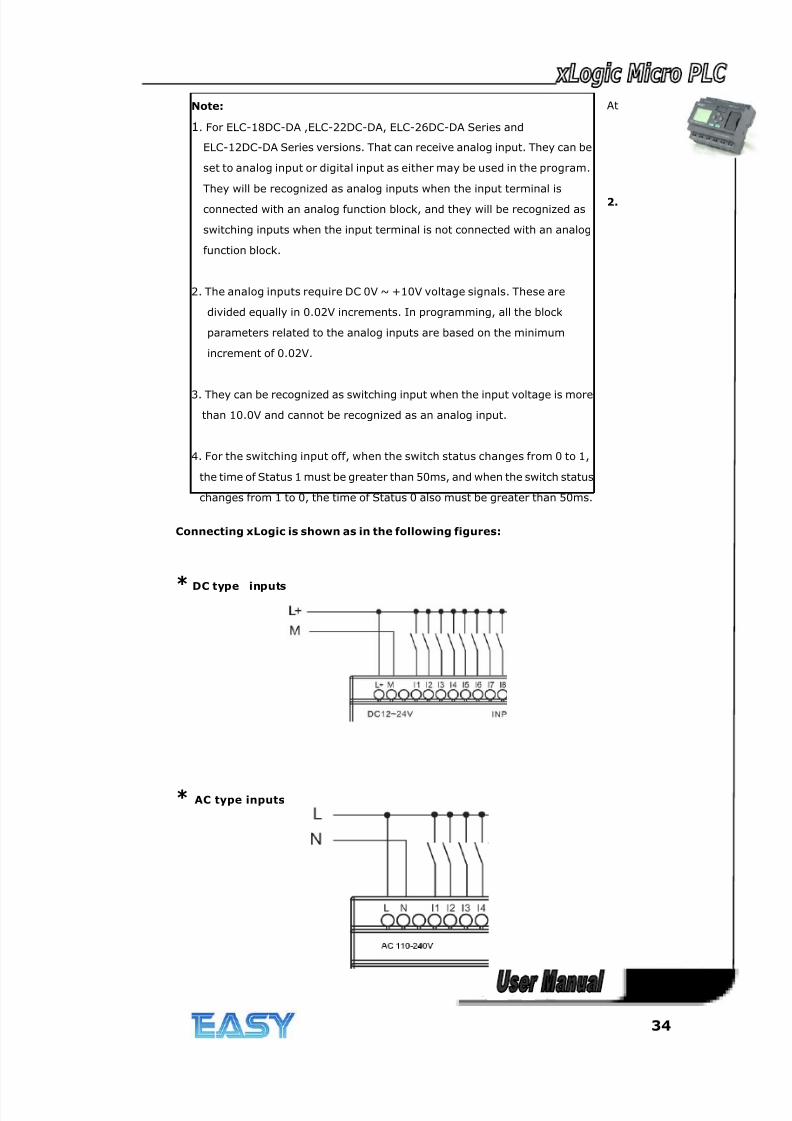
Connecting xLogic is shown as in the following figures:
* DC type inputs
* AC type inputs
Note:
1. For ELC-18DC-DA ,ELC-22DC-DA, ELC-26DC-DA Series and
ELC-12DC-DA Series versions. That can receive analog input. They can be
set to analog input or digital input as either may be used in the program.
They will be recognized as analog inputs when the input terminal is
connected with an analog function block, and they will be recognized as
switching inputs when the input terminal is not connected with an analog
function block.
2. The analog inputs require DC 0V ~ +10V voltage signals. These are
divided equally in 0.02V increments. In programming, all the block
parameters related to the analog inputs are based on the minimum
increment of 0.02V.
3. They can be recognized as switching input when the input voltage is more
than 10.0V and cannot be recognized as an analog input.
4. For the switching input off, when the switch status changes from 0 to 1,
the time of Status 1 must be greater than 50ms, and when the switch status
changes from 1 to 0, the time of Status 0 also must be greater than 50ms.
8/20/2019 XLogic User's Manual2
http://slidepdf.com/reader/full/xlogic-users-manual2 35/338
35
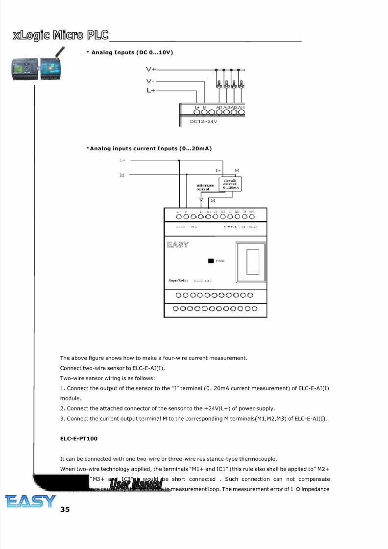
* Analog Inputs (DC 0…10V)
*Analog inputs current Inputs (0…20mA)
The above figure shows how to make a four-wire current measurement.
Connect two-wire sensor to ELC-E-AI(I).
Two-wire sensor wiring is as follows:
1. Connect the output of the sensor to the “I” terminal (0…20mA current measurement) of ELC-E-AI(I)
module.
2. Connect the attached connector of the sensor to the +24V(L+) of power supply.
3. Connect the current output terminal M to the corresponding M terminals(M1,M2,M3) of ELC-E-AI(I).
ELC-E-PT100
It can be connected with one two-wire or three-wire resistance-type thermocouple.
When two-wire technology applied, the terminals “M1+ and IC1” (this rule also shall be applied to” M2+
and IC2”, “M3+ and IC3” ) would be short connected . Such connection can not compensate
error/tolerance caused by the resistance in measurement loop. The measurement error of 1 Ω impedance
8/20/2019 XLogic User's Manual2
http://slidepdf.com/reader/full/xlogic-users-manual2 36/338
36
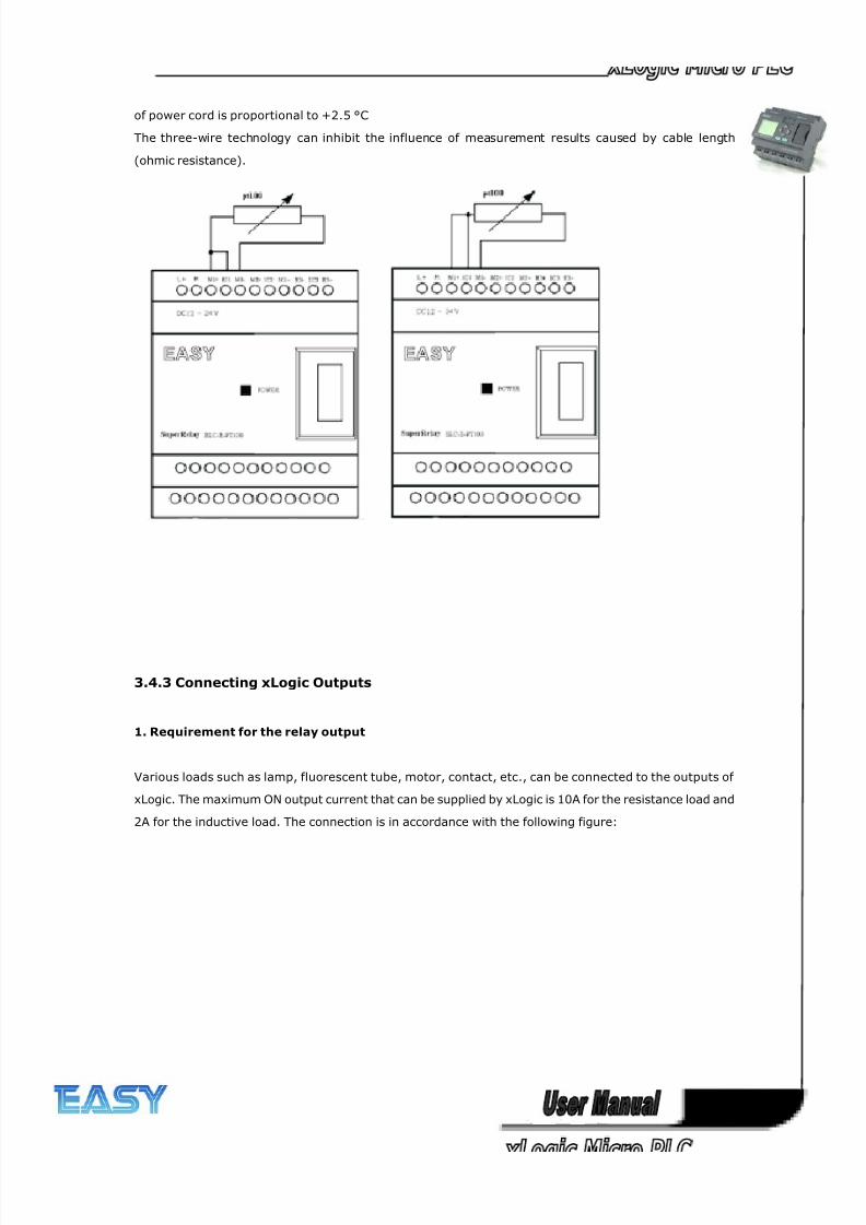
of power cord is proportional to +2.5 °C
The three-wire technology can inhibit the influence of measurement results caused by cable length
(ohmic resistance).
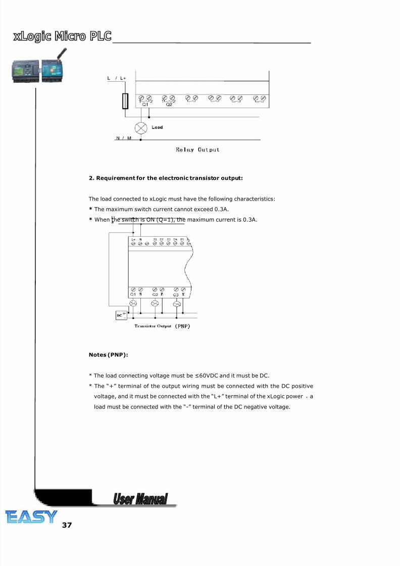
3.4.3 Connecting xLogic Outputs
1. Requirement for the relay output
Various loads such as lamp, fluorescent tube, motor, contact, etc., can be connected to the outputs of
xLogic. The maximum ON output current that can be supplied by xLogic is 10A for the resistance load and
2A for the inductive load. The connection is in accordance with the following figure:
8/20/2019 XLogic User's Manual2
http://slidepdf.com/reader/full/xlogic-users-manual2 37/338
37
2. Requirement for the electronic transistor output:
The load connected to xLogic must have the following characteristics:
* The maximum switch current cannot exceed 0.3A.
* When the switch is ON (Q=1), the maximum current is 0.3A.
Notes (PNP):
* The load connecting voltage must be ≤60VDC and it must be DC.
* The “+” terminal of the output wiring must be connected with the DC positive
voltage, and it must be connected with the “L+” terminal of the xLogic power ,a
load must be connected with the “-” terminal of the DC negative voltage.
8/20/2019 XLogic User's Manual2
http://slidepdf.com/reader/full/xlogic-users-manual2 38/338
38
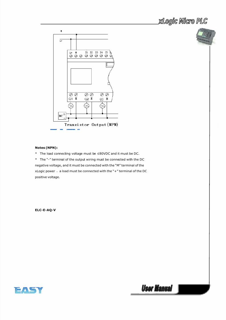
Notes (NPN):
* The load connecting voltage must be ≤80VDC and it must be DC.
* The “-” terminal of the output wiring must be connected with the DC
negative voltage, and it must be connected with the “M” terminal of the
xLogic power ,a load must be connected with the “+” terminal of the DC
positive voltage.
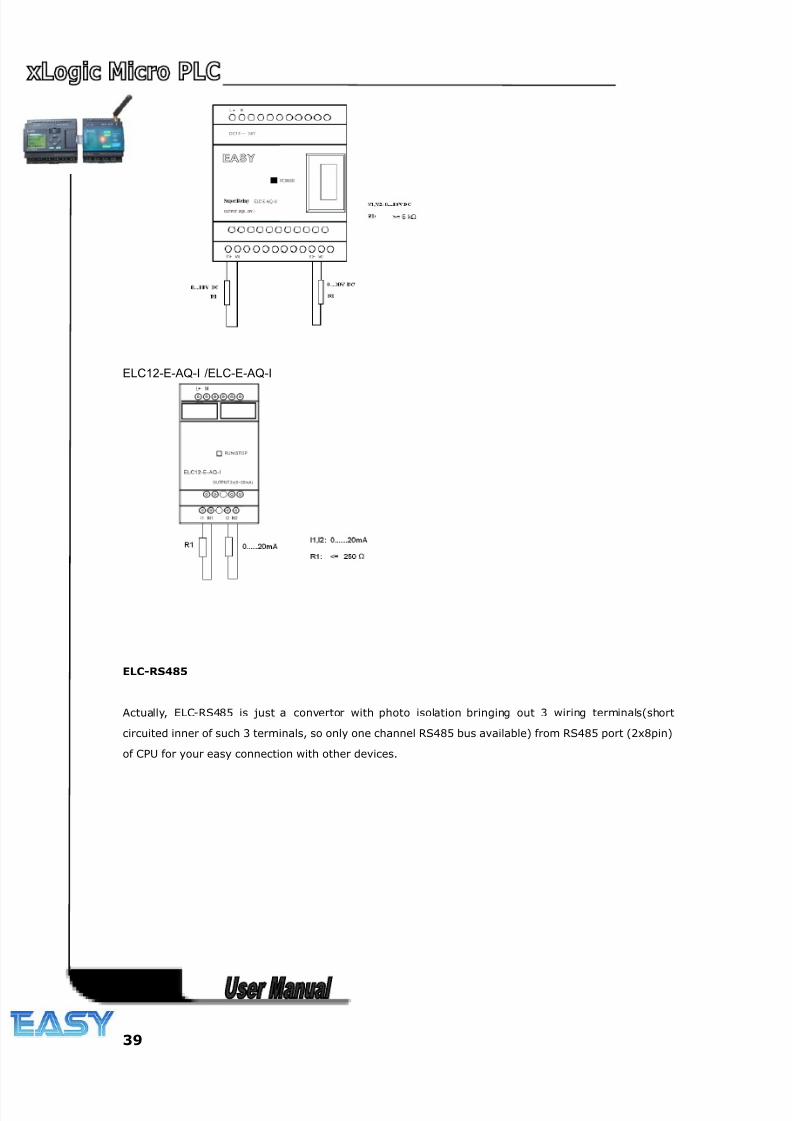
ELC-E-AQ-V
8/20/2019 XLogic User's Manual2
http://slidepdf.com/reader/full/xlogic-users-manual2 39/338
39
ELC12-E-AQ-I /ELC-E-AQ-I
ELC-RS485
Actually, ELC-RS485 is just a convertor with photo isolation bringing out 3 wiring terminals(short
circuited inner of such 3 terminals, so only one channel RS485 bus available) from RS485 port (2x8pin)
of CPU for your easy connection with other devices.
8/20/2019 XLogic User's Manual2
http://slidepdf.com/reader/full/xlogic-users-manual2 40/338
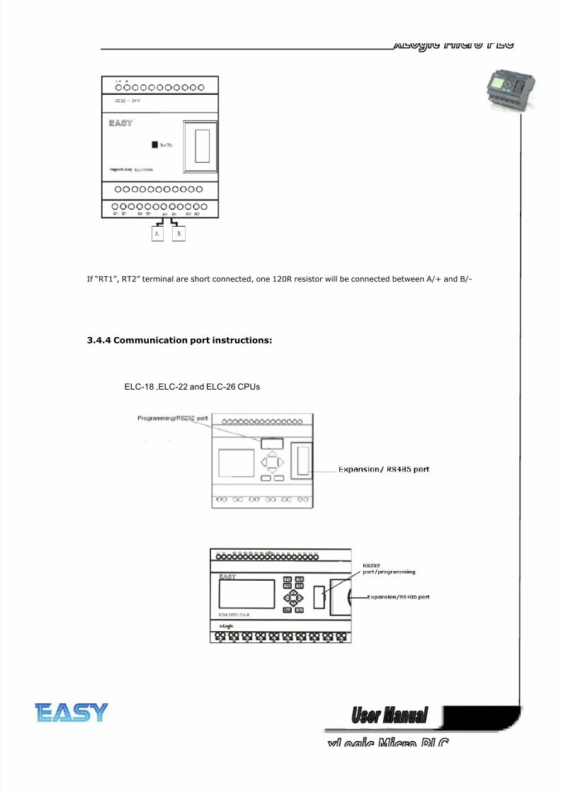
40
If “RT1”, RT2” terminal are short connected, one 120R resistor will be connected between A/+ and B/-
3.4.4 Communication port instructions:
ELC-18 ,ELC-22 and ELC-26 CPUs
8/20/2019 XLogic User's Manual2
http://slidepdf.com/reader/full/xlogic-users-manual2 41/338
41
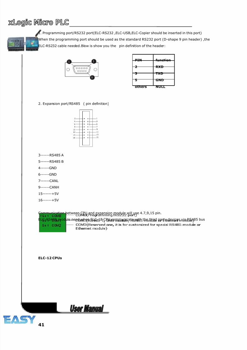
1. Programming port/RS232 port(ELC-RS232 ,ELC-USB,ELC-Copier should be inserted in this port)
When the programming port should be used as the standard RS232 port (D-shape 9 pin header) ,the
ELC-RS232 cable needed.Blow is show you the pin definition of the header:
2. Expansion port/RS485 ( pin definition)
3------RS485 A
5------RS485 B
4------GND
6------GND
7------CANL
9------CANH
15------+5V
16------+5V
Communication between CPU and expansion module will use 4.7,9,15 pin.
ELC-RS485 module need when ELC-18 CPU communicate with the third party devices via RS485 bus
ELC-12 CPUs
PIN function
2 RXD
3 TXD
5 GND
others NULL
8/20/2019 XLogic User's Manual2
http://slidepdf.com/reader/full/xlogic-users-manual2 42/338
42
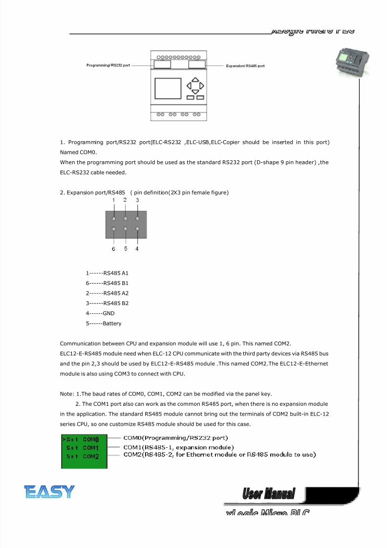
1. Programming port/RS232 port(ELC-RS232 ,ELC-USB,ELC-Copier should be inserted in this port)
Named COM0.
When the programming port should be used as the standard RS232 port (D-shape 9 pin header) ,the
ELC-RS232 cable needed.
2. Expansion port/RS485 ( pin definition(2X3 pin female figure)
1------RS485 A1
6------RS485 B1
2------RS485 A2
3------RS485 B2
4------GND
5------Battery
Communication between CPU and expansion module will use 1, 6 pin. This named COM2.
ELC12-E-RS485 module need when ELC-12 CPU communicate with the third party devices via RS485 bus
and the pin 2,3 should be used by ELC12-E-RS485 module .This named COM2.The ELC12-E-Ethernet
module is also using COM3 to connect with CPU.
Note: 1.The baud rates of COM0, COM1, COM2 can be modified via the panel key.
2. The COM1 port also can work as the common RS485 port, when there is no expansion module
in the application. The standard RS485 module cannot bring out the terminals of COM2 built-in ELC-12
series CPU, so one customize RS485 module should be used for this case.
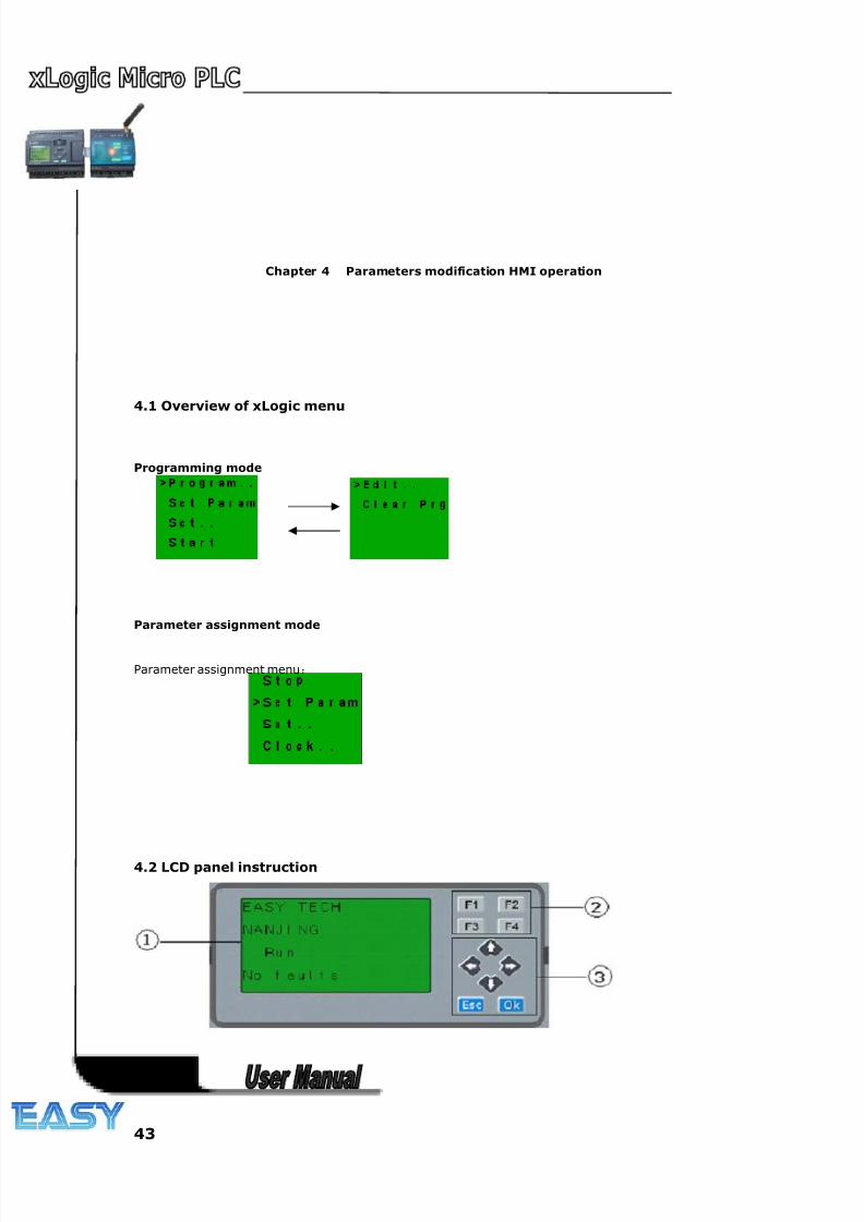
8/20/2019 XLogic User's Manual2
http://slidepdf.com/reader/full/xlogic-users-manual2 43/338
43
Chapter 4 Parameters modification HMI operation
4.1 Overview of xLogic menu
Programming mode
Parameter assignment mode
Parameter assignment menu:
4.2 LCD panel instruction
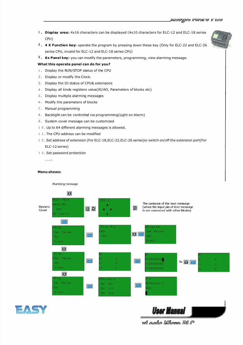
8/20/2019 XLogic User's Manual2
http://slidepdf.com/reader/full/xlogic-users-manual2 44/338
44
1
. Display area: 4x16 characters can be displayed (4x10 characters for ELC-12 and ELC-18 series
CPU)
2
. 4 X Function key: operate the program by pressing down these key (Only for ELC-22 and ELC-26
series CPU, invalid for ELC-12 and ELC-18 series CPU)
3
. 6x Panel key: you can modify the parameters, programming, view alarming message.
What this operate panel can do for you?
1. Display the RUN/STOP status of the CPU
2. Display or modify the Clock.
3. Display the IO status of CPU& extensions
4. Display all kinds registers value(AI/AO, Parameters of blocks etc)
5. Display multiple alarming messages
6. Modify the parameters of blocks
7. Manual programming
8. Backlight can be controlled via programming(Light on Alarm)
9. System cover message can be customized
10. Up to 64 different alarming messages is allowed.
11. The CPU address can be modified
12. Set address of extension (For ELC-18,ELC-22,ELC-26 series)or switch on/off the extension port(For
ELC-12 series)
13. Set password protection
……..
Menu shows:
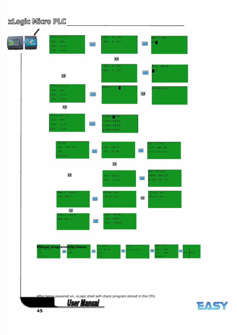
8/20/2019 XLogic User's Manual2
http://slidepdf.com/reader/full/xlogic-users-manual2 45/338
45
Manual programming menu:
After being powered on, xLogic shall self-check program stored in the CPU.
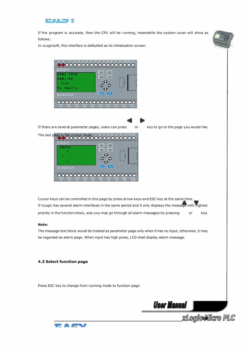
8/20/2019 XLogic User's Manual2
http://slidepdf.com/reader/full/xlogic-users-manual2 46/338
46
If the program is accurate, then the CPU will be running, meanwhile the system cover will show as
follows:
In xLogicsoft, this interface is defaulted as its initialization screen.
If there are several parameter pages, users can press or key to go to the page you would like.
The last page is the cursor mode:
Cursor keys can be controlled in this page by press arrow keys and ESC key at the same time.
If xLogic has several alarm interfaces in the same period and it only displays the message with highest
priority in the function block, also you may go through all alarm messages by pressing or key.
Note:
The message text block would be treated as parameter page only when it has no input, otherwise, it may
be regarded as alarm page. When input has high pulse, LCD shall display alarm message.
4.3 Select function page
Press ESC key to change from running mode to function page.
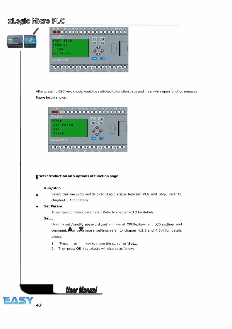
8/20/2019 XLogic User's Manual2
http://slidepdf.com/reader/full/xlogic-users-manual2 47/338
47
After pressing ESC key, xLogic would be switched to function page and meanwhile open function menu as
figure below shows.
Brief introduction on 5 options of function page:
Run/stop
Select this menu to switch over xLogic status between RUN and Stop. Refer to
chapter4.3.1 for details.
Set Param
To set function block parameter. Refer to chapter 4.3.2 for details.
Set…
Used to set /modify password ,set address of CPU&extension , LCD settings and
communication parameters settings refer to chapter 4.3.3 and 4.3.4 for details
please.
1. ”Press or key to move the cursor to “Set….
2. Then press OK key ,xLogic will display as follows:
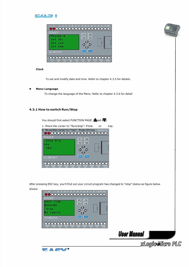
8/20/2019 XLogic User's Manual2
http://slidepdf.com/reader/full/xlogic-users-manual2 48/338
48
Clock
To set and modify date and time .Refer to chapter 4.3.5 for details.
Menu Language
To change the language of the Menu. Refer to chapter 4.3.6 for detail
4.3.1 How to switch Run/Stop
You should first select FUNCTION PAGE. (Read 4.3)
1. Move the cursor to “Run/stop”: Press or key.
2. Move the cursor to "Yes": Press OK key.
After pressing ESC key, you’ll find out your circuit program has changed to “stop” status as figure below
shows:
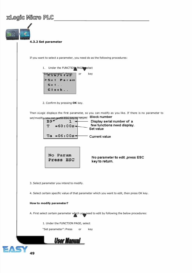
8/20/2019 XLogic User's Manual2
http://slidepdf.com/reader/full/xlogic-users-manual2 49/338
49
4.3.2 Set parameter
If you want to select a parameter, you need do as the following procedures:
1. Under the FUNCTION PAGE, select
“Set parameter”: Press or key
2. Confirm by pressing OK key.
Then xLogic displays the first parameter, so you can modify as you like. If there is no parameter to
set/modify, you can press ESC key to return.
3. Select parameter you intend to modify.
4. Select certain specific value of that parameter which you want to edit, then press OK key.
How to modify parameter?
A. First select certain parameter which you need to edit by following the below procedures:
1. Under the FUNCTION PAGE, select
“Set parameter”: Press or key
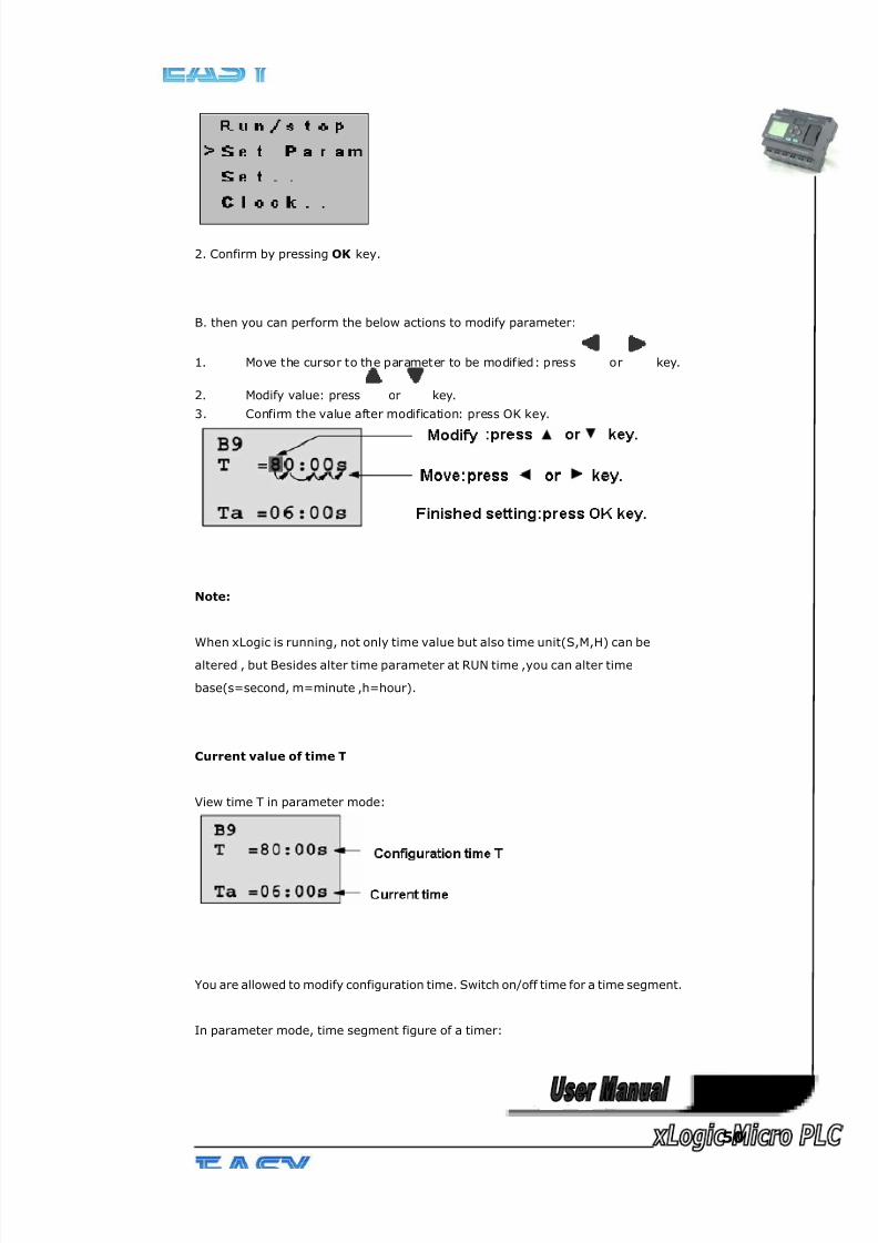
8/20/2019 XLogic User's Manual2
http://slidepdf.com/reader/full/xlogic-users-manual2 50/338
50
2. Confirm by pressing OK key.
B. then you can perform the below actions to modify parameter:
1. Move the cursor to the parameter to be modified: press or key.
2. Modify value: press or key.
3. Confirm the value after modification: press OK key.
Note:
When xLogic is running, not only time value but also time unit(S,M,H) can be
altered , but Besides alter time parameter at RUN time ,you can alter time
base(s=second, m=minute ,h=hour).
Current value of time T
View time T in parameter mode:
You are allowed to modify configuration time. Switch on/off time for a time segment.
In parameter mode, time segment figure of a timer:
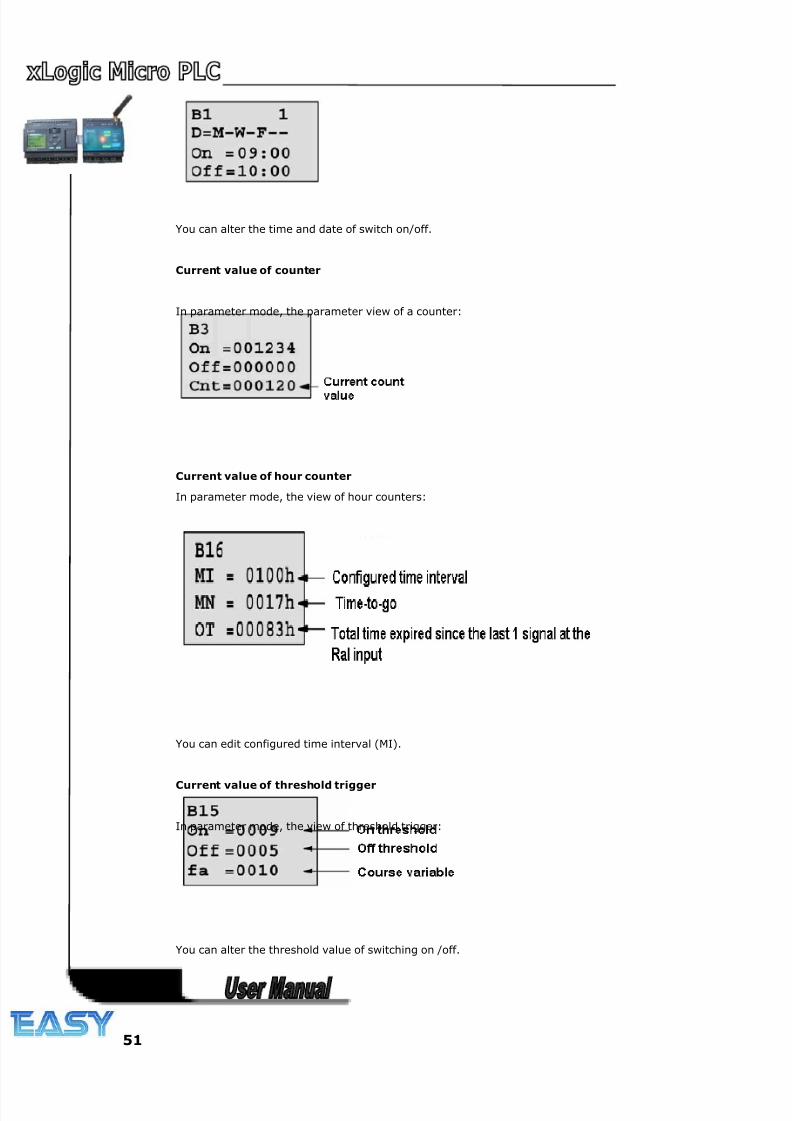
8/20/2019 XLogic User's Manual2
http://slidepdf.com/reader/full/xlogic-users-manual2 51/338
51
You can alter the time and date of switch on/off.
Current value of counter
In parameter mode, the parameter view of a counter:
Current value of hour counter
In parameter mode, the view of hour counters:
You can edit configured time interval (MI).
Current value of threshold trigger
In parameter mode, the view of threshold trigger:
You can alter the threshold value of switching on /off.
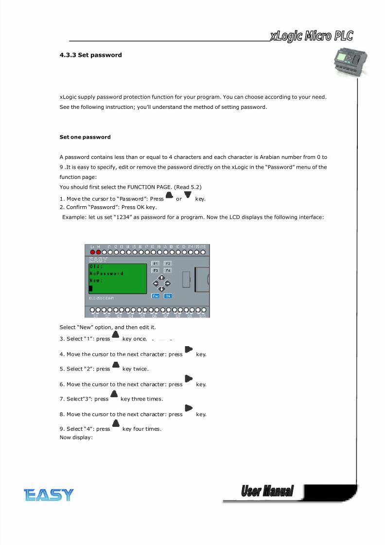
8/20/2019 XLogic User's Manual2
http://slidepdf.com/reader/full/xlogic-users-manual2 52/338
52
4.3.3 Set password
xLogic supply password protection function for your program. You can choose according to your need.
See the following instruction; you’ll understand the method of setting password.
Set one password
A password contains less than or equal to 4 characters and each character is Arabian number from 0 to
9 .It is easy to specify, edit or remove the password directly on the xLogic in the “Password” menu of the
function page:
You should first select the FUNCTION PAGE. (Read 5.2)
1. Move the cursor to “Password”: Press or key.
2. Confirm “Password”: Press OK key.
Example: let us set “1234” as password for a program. Now the LCD displays the following interface:
Select “New” option, and then edit it.
3. Select “1”: press key once.
4. Move the cursor to the next character: press key.
5. Select “2”: press key twice.
6. Move the cursor to the next character: press key.
7. Select”3”: press key three times.
8. Move the cursor to the next character: press key.
9. Select “4”: press key four times.
Now display:
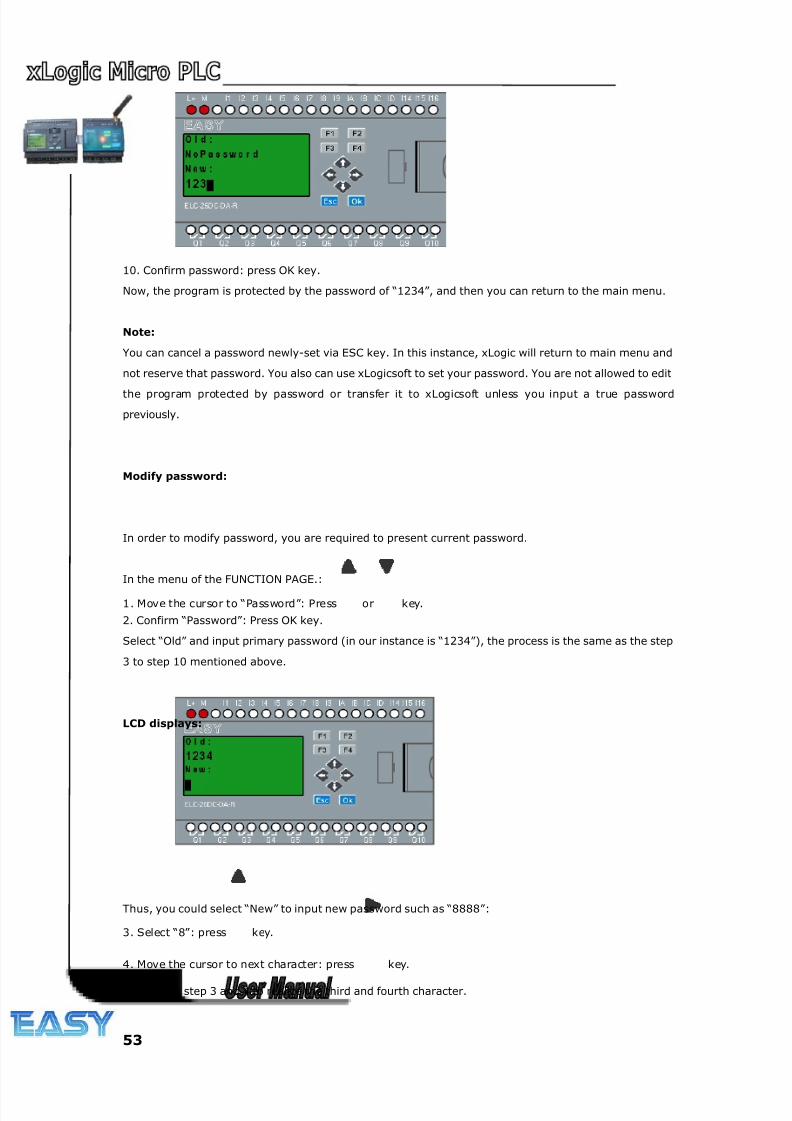
8/20/2019 XLogic User's Manual2
http://slidepdf.com/reader/full/xlogic-users-manual2 53/338
53
10. Confirm password: press OK key.
Now, the program is protected by the password of “1234”, and then you can return to the main menu.
Note:
You can cancel a password newly-set via ESC key. In this instance, xLogic will return to main menu and
not reserve that password. You also can use xLogicsoft to set your password. You are not allowed to edit
the program protected by password or transfer it to xLogicsoft unless you input a true password
previously.
Modify password:
In order to modify password, you are required to present current password.
In the menu of the FUNCTION PAGE.:
1. Move the cursor to “Password”: Press or key.
2. Confirm “Password”: Press OK key.
Select “Old” and input primary password (in our instance is “1234”), the process is the same as the step
3 to step 10 mentioned above.
LCD displays:
Thus, you could select “New” to input new password such as “8888”:
3. Select “8”: press key.
4. Move the cursor to next character: press key.
Repeat the step 3 and 4 to realize the third and fourth character.
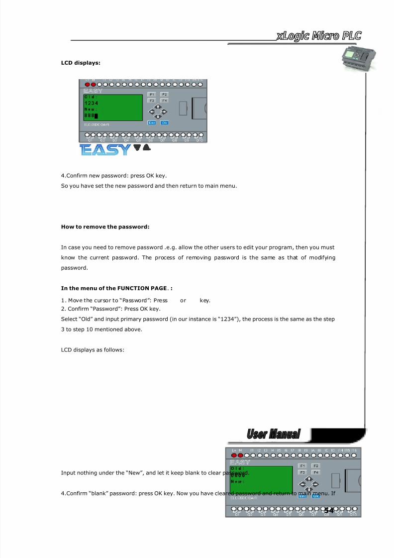
8/20/2019 XLogic User's Manual2
http://slidepdf.com/reader/full/xlogic-users-manual2 54/338
54
LCD displays:
4.Confirm new password: press OK key.
So you have set the new password and then return to main menu.
How to remove the password:
In case you need to remove password .e.g. allow the other users to edit your program, then you must
know the current password. The process of removing password is the same as that of modifying
password.
In the menu of the FUNCTION PAGE. :
1. Move the cursor to “Password”: Press or key.
2. Confirm “Password”: Press OK key.
Select “Old” and input primary password (in our instance is “1234”), the process is the same as the step
3 to step 10 mentioned above.
LCD displays as follows:
Input nothing under the “New”, and let it keep blank to clear password.
4.Confirm “blank” password: press OK key. Now you have cleared password and return to main menu. If
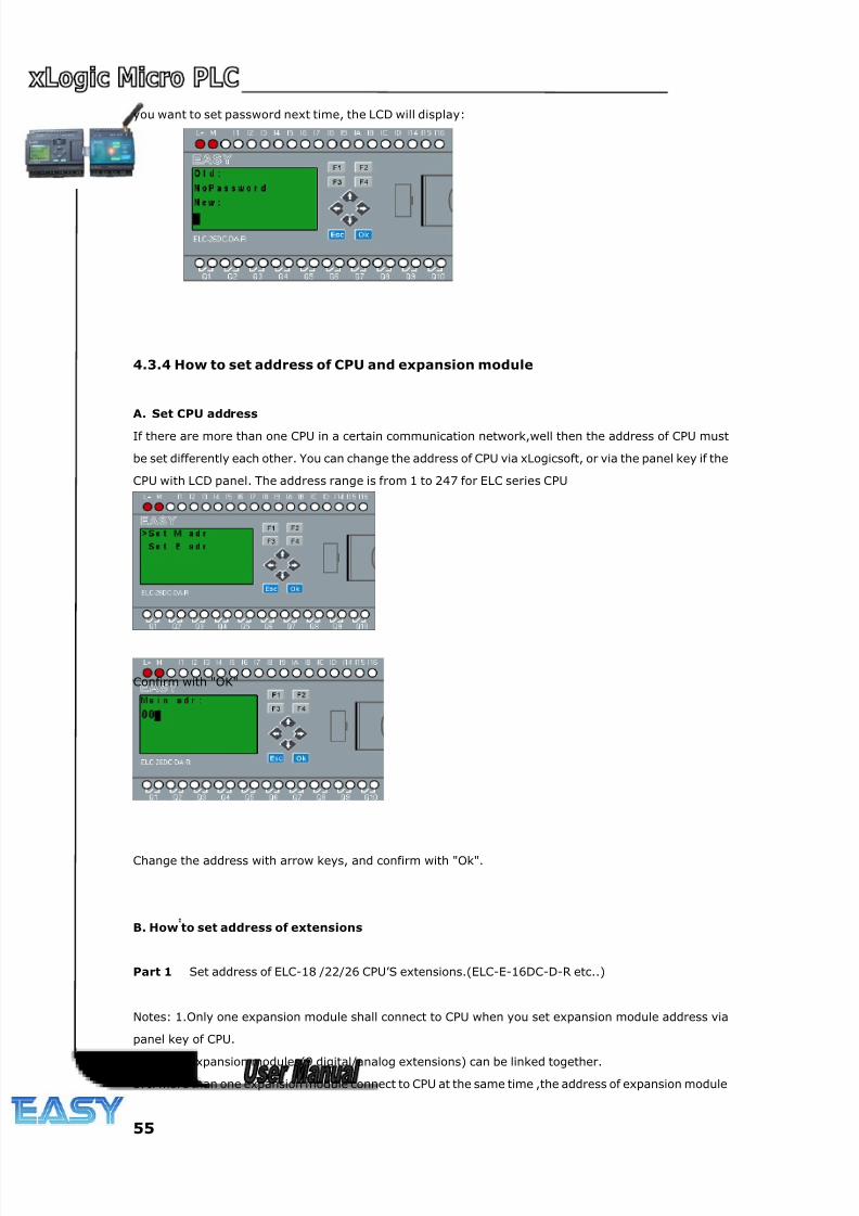
8/20/2019 XLogic User's Manual2
http://slidepdf.com/reader/full/xlogic-users-manual2 55/338
55
you want to set password next time, the LCD will display:
4.3.4 How to set address of CPU and expansion module
A. Set CPU address
If there are more than one CPU in a certain communication network,well then the address of CPU must
be set differently each other. You can change the address of CPU via xLogicsoft, or via the panel key if the
CPU with LCD panel. The address range is from 1 to 247 for ELC series CPU
Confirm with "OK"
Change the address with arrow keys, and confirm with "Ok".
B. How to set address of extensions
Part 1 :
Set address of ELC-18 /22/26 CPU’S extensions.(ELC-E-16DC-D-R etc..)
Notes: 1.Only one expansion module shall connect to CPU when you set expansion module address via
panel key of CPU.
2.Up to 9 expansion modules(9 digital/analog extensions) can be linked together.
3. If more than one expansion module connect to CPU at the same time ,the address of expansion module
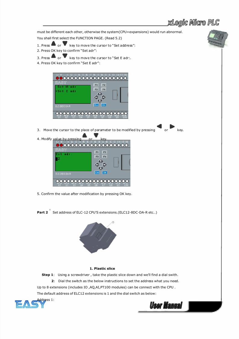
8/20/2019 XLogic User's Manual2
http://slidepdf.com/reader/full/xlogic-users-manual2 56/338
56
must be different each other, otherwise the system(CPU+expansions) would run abnormal.
You shall first select the FUNCTION PAGE. (Read 5.2)
1. Press or key to move the cursor to “Set address”:
2. Press OK key to confirm “Set adr”:
3. Press or key to move the cursor to “Set E adr:.4. Press OK key to confirm “Set E adr”:
3. Move the cursor to the place of parameter to be modified by pressing or key.
4. Modify value by pressing or key.
5. Confirm the value after modification by pressing OK key.
Part 2 :Set address of ELC-12 CPU’S extensions.(ELC12-8DC-DA-R etc..)
1. Plastic slice
Step 1: Using a screwdriver , take the plastic slice down and we’ll find a dial swith.
2: Dial the switch as the below instructions to set the address what you need.
Up to 8 extensions (includes IO ,AQ,AI,PT100 modules) can be connect with the CPU .
The default address of ELC12 extensions is 1 and the dial switch as below:
Address 1:
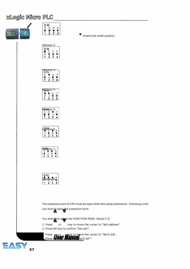
8/20/2019 XLogic User's Manual2
http://slidepdf.com/reader/full/xlogic-users-manual2 57/338
57
means the swith position
Address 2:
Address 3:
Address 4:
Address 5:
Address 6:
Address 7:
Address 8:
The expansion port of CPU must be open when the using extensions . Following is tell
you how to open the expansion port:
You shall first select the FUNCTION PAGE. (Read 5.2)
1. Press or key to move the cursor to “Set address”:
2. Press OK key to confirm “Set adr”:
3. Press or key to move the cursor to “Set E adr:.4. Press OK key to confirm “Set E adr”:
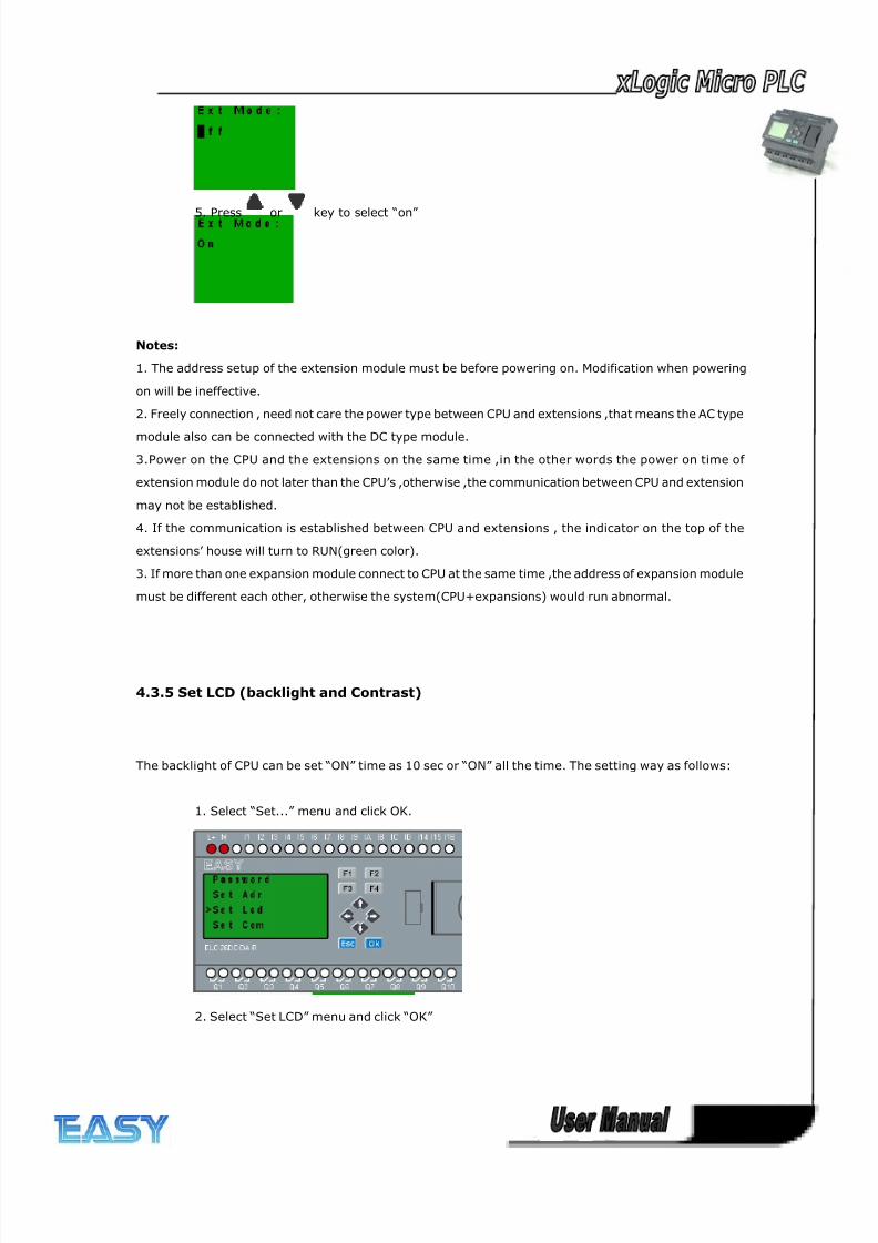
8/20/2019 XLogic User's Manual2
http://slidepdf.com/reader/full/xlogic-users-manual2 58/338
58
5. Press or key to select “on”
Notes:
1. The address setup of the extension module must be before powering on. Modification when powering
on will be ineffective.
2. Freely connection , need not care the power type between CPU and extensions ,that means the AC type
module also can be connected with the DC type module.
3.Power on the CPU and the extensions on the same time ,in the other words the power on time of
extension module do not later than the CPU’s ,otherwise ,the communication between CPU and extension
may not be established.
4. If the communication is established between CPU and extensions , the indicator on the top of the
extensions’ house will turn to RUN(green color).
3. If more than one expansion module connect to CPU at the same time ,the address of expansion module
must be different each other, otherwise the system(CPU+expansions) would run abnormal.
4.3.5 Set LCD (backlight and Contrast)
The backlight of CPU can be set “ON” time as 10 sec or “ON” all the time. The setting way as follows:
1. Select “Set...” menu and click OK.
2. Select “Set LCD” menu and click “OK”
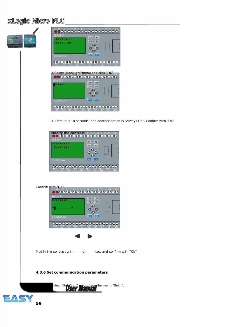
8/20/2019 XLogic User's Manual2
http://slidepdf.com/reader/full/xlogic-users-manual2 59/338
59
3.Select "Backlight"menu and click "OK"
4. Default is 10 seconds, and another option is "Always On". Confirm with "OK"
Modify the contrast
Confirm with "OK"
Modify the contrast with or key, and confirm with "Ok".
4.3.6 Set communication parameters
Select "Set Com" menu from the menu "Set..".
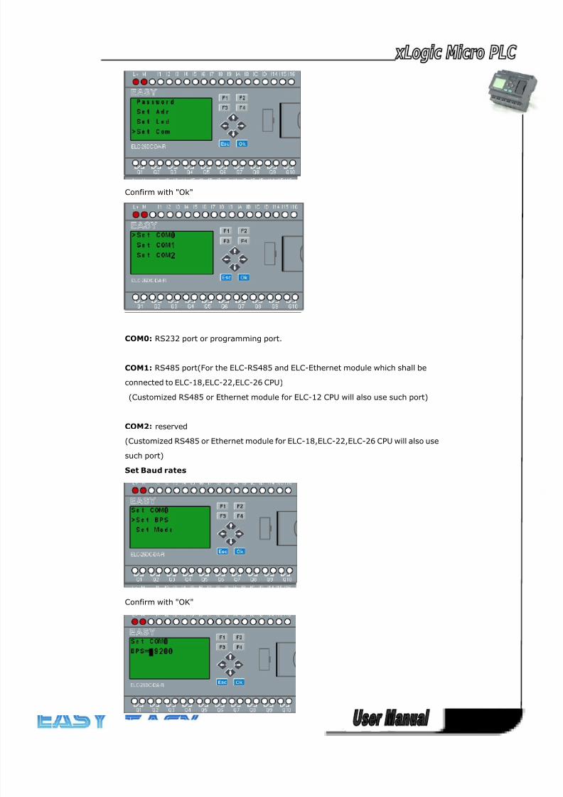
8/20/2019 XLogic User's Manual2
http://slidepdf.com/reader/full/xlogic-users-manual2 60/338
60
Confirm with "Ok"
COM0: RS232 port or programming port.
COM1: RS485 port(For the ELC-RS485 and ELC-Ethernet module which shall be
connected to ELC-18,ELC-22,ELC-26 CPU)
(Customized RS485 or Ethernet module for ELC-12 CPU will also use such port)
COM2: reserved
(Customized RS485 or Ethernet module for ELC-18,ELC-22,ELC-26 CPU will also use
such port)
Set Baud rates
Confirm with "OK"
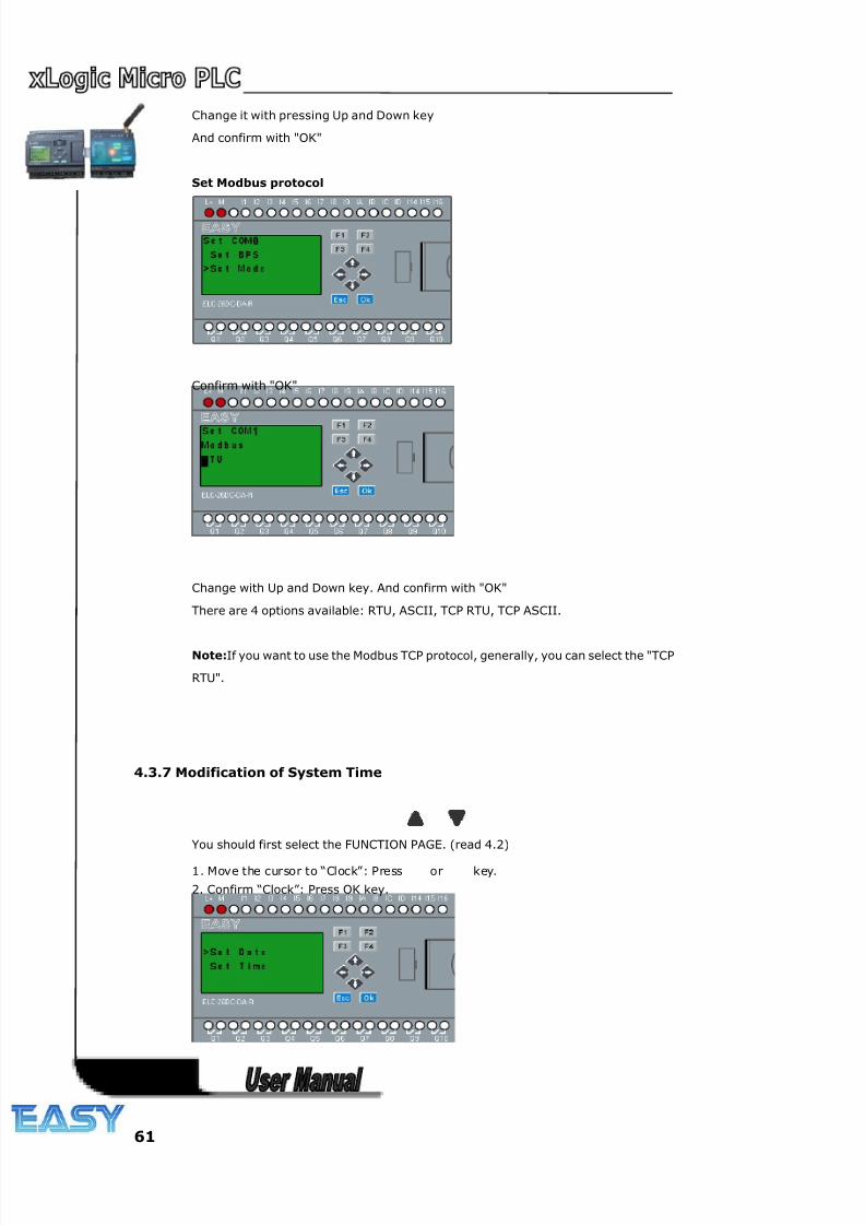
8/20/2019 XLogic User's Manual2
http://slidepdf.com/reader/full/xlogic-users-manual2 61/338
61
Change it with pressing Up and Down key
And confirm with "OK"
Set Modbus protocol
Confirm with "OK"
Change with Up and Down key. And confirm with "OK"
There are 4 options available: RTU, ASCII, TCP RTU, TCP ASCII.
Note:If you want to use the Modbus TCP protocol, generally, you can select the "TCP
RTU".
4.3.7 Modification of System Time
You should first select the FUNCTION PAGE. (read 4.2)
1. Move the cursor to “Clock”: Press or key.
2. Confirm “Clock”: Press OK key.
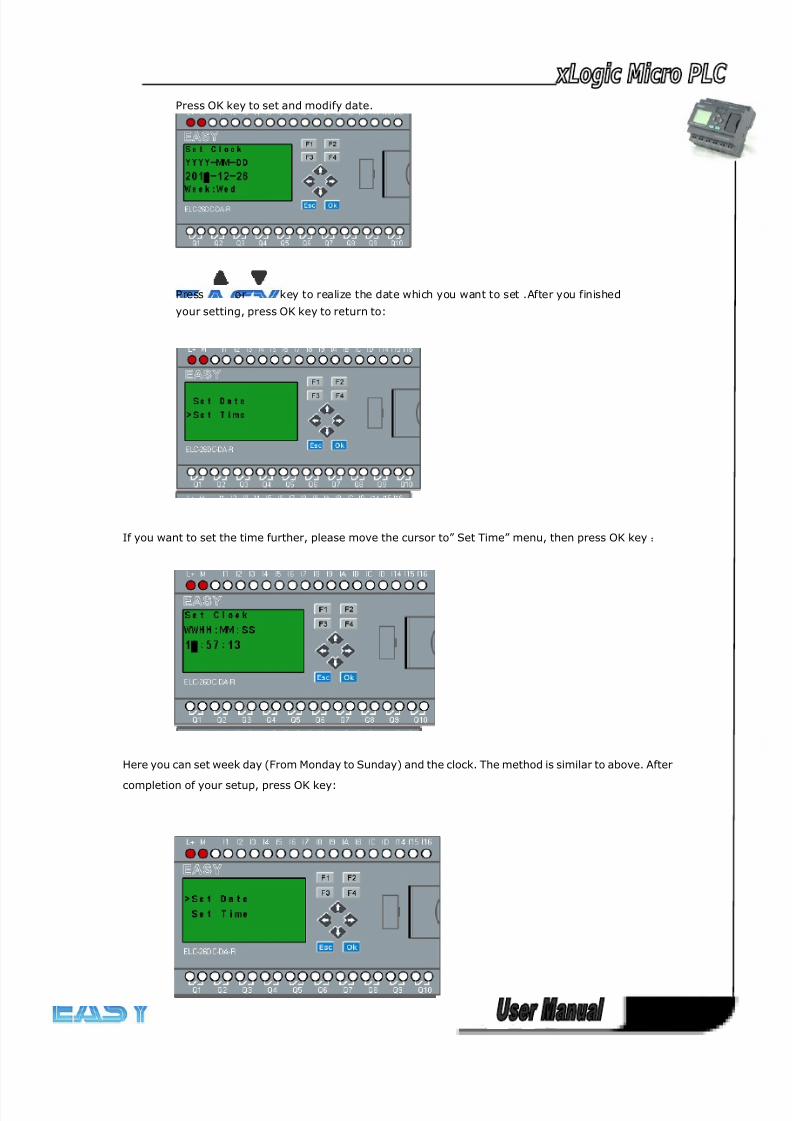
8/20/2019 XLogic User's Manual2
http://slidepdf.com/reader/full/xlogic-users-manual2 62/338
62
Press OK key to set and modify date.
Press or key to realize the date which you want to set .After you finished
your setting, press OK key to return to:
If you want to set the time further, please move the cursor to” Set Time” menu, then press OK key:
Here you can set week day (From Monday to Sunday) and the clock. The method is similar to above. After
completion of your setup, press OK key:
8/20/2019 XLogic User's Manual2
http://slidepdf.com/reader/full/xlogic-users-manual2 63/338
63
Press ESC key and return to FUNCTION PAGE.
Chapter 5 Programming via panel key
Note:
Only the standard ELC-12 series ,upgraded ELC-18 CPU , ELC-22 and ELC-26 CPU supports the
programming via HMI panel key, standard ELC-18 & economic ELC-18 without such feature.
Getting started with xLogic
Programming refers to creating a circuit program from the xLogic Basic module.
In this chapter you will learn how to use xLogic to create the xLogic circuit programs for your application.
xLogicSoft is the xLogic programming software that you can use on your PC to
quickly and easily create, test, modify, save and print the circuit programs. The topics in this manual,
however, relate only to the creation of circuit programs on the actual xLogic Basic module. The
programming software xLogicSoft contains extensive online help.
A small example in the first part of this chapter introduces the operating principles of xLogic:
● You will learn the meaning of two basic terms, namely the connector and the block.
● As the next step, you will create a circuit program based on a simple conventional circuit.
● Lastly, you will enter this program directly in xLogic.
It will take you only a few pages of this manual to store your first executable circuit program
in the xLogic unit. With suitable hardware (switches etc.), you will then be able to carry out
initial tests.
5.1 Connectors
xLogic is equipped with inputs and outputs
Example of a configuration with several modules:
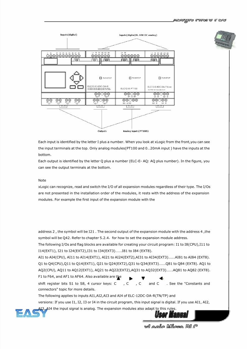
8/20/2019 XLogic User's Manual2
http://slidepdf.com/reader/full/xlogic-users-manual2 64/338
64
Each input is identified by the letter I plus a number. When you look at xLogic from the front,you can see
the input terminals at the top. Only analog modules(PT100 and 0…20mA input ) have the inputs at the
bottom.
Each output is identified by the letter Q plus a number (ELC-E- AQ: AQ plus number). In the figure, you
can see the output terminals at the bottom.
Note
xLogic can recognize, read and switch the I/O of all expansion modules regardless of their type. The I/Os
are not presented in the installation order of the modules, it rests with the address of the expansion
modules. For example the first input of the expansion module with the
address 2 , the symbol will be I21 . The second output of the expansion module with the address 4 ,the
symbol will be Q42. Refer to chapter 5.2.4,for how to set the expansion module address.
The following I/Os and flag blocks are available for creating your circuit program: I1 to I8(CPU),I11 to
I14(EXT1), I21 to I24(EXT2),I31 to I34(EXT3)…….I81 to I84 (EXT8).
AI1 to AI4(CPU), AI11 to AI14(EXT1), AI21 to AI24(EXT2),AI31 to AI34(EXT3)…….AI81 to AI84 (EXT8).
Q1 to Q4(CPU),Q11 to Q14(EXT1), Q21 to Q24(EXT2),Q31 to Q34(EXT3)…….Q81 to Q84 (EXT8). AQ1 to
AQ2(CPU), AQ11 to AQ12(EXT1), AQ21 to AQ22(EXT2),AQ31 to AQ32(EXT3)…….AQ81 to AQ82 (EXT8).
F1 to F64, and AF1 to AF64. Also available are the
shift register bits S1 to S8, 4 cursor keys: C , C , C and C . See the "Constants and
connectors" topic for more details.
The following applies to inputs AI1,AI2,AI3 and AI4 of ELC-12DC-DA-R(TN/TP) and
versions: If you use I1, I2, I3 or I4 in the circuit program, this input signal is digital. If you use AI1, AI2,
AI3, AI4 the input signal is analog. The expansion modules also adapt to this rules.
8/20/2019 XLogic User's Manual2
http://slidepdf.com/reader/full/xlogic-users-manual2 65/338
65
The illustration above with numbered AI inputs shows the conceptual usage of the inputs, not the actual
physical markings on the module.
xLogic's connectors
The term connector refers to all connections and states in xLogic .
The digital I/O status can be '0' or '1'. Status '0' means that the input does not carry a specific voltage.
Status '1' means that the input does carry a specific voltage.
The 'hi', 'lo' connectors have been introduced to make it easier for you to create the
circuit program:
'hi' (high) is assigned the status '1',
'lo' (low) is assigned the status '0'.
You do not have to use all of the connectors of a block. The circuit program automatically assigns the
unused connectors a status that ensures proper functioning of the relevant block. For information on the
meaning of the term "block", refer to the topic on "Blocks and block numbers ".
5.2 Blocks and block numbers
This chapter shows you how to use xLogic elements to create complex circuits and how blocks and I/O
are interconnected.
In the topic "From circuit diagram to xLogic Program" you will learn how to transform a conventional
circuit into a xLogic circuit program.
Blocks
A block in xLogic represents a function that is used to convert input information into output information.
Previously you had to wire the individual elements in a control cabinet or terminal box.
When you create the circuit program, you interconnect the blocks. To do so, simply select the connection
you require from the Co menu. The menu name Co is an abbreviation of the term "Connector".
Logic operations
The most elementary blocks are the logic operations:
● AND
● OR
● …
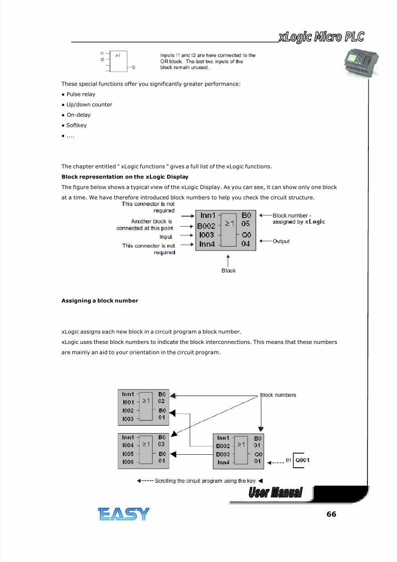
8/20/2019 XLogic User's Manual2
http://slidepdf.com/reader/full/xlogic-users-manual2 66/338
66
These special functions offer you significantly greater performance:
● Pulse relay
● Up/down counter
● On-delay
● Softkey
● ....
The chapter entitled " xLogic functions " gives a full list of the xLogic functions.
Block representation on the xLogic Display
The figure below shows a typical view of the xLogic Display. As you can see, it can show only one block
at a time. We have therefore introduced block numbers to help you check the circuit structure.
Assigning a block number
xLogic assigns each new block in a circuit program a block number.
xLogic uses these block numbers to indicate the block interconnections. This means that these numbers
are mainly an aid to your orientation in the circuit program.
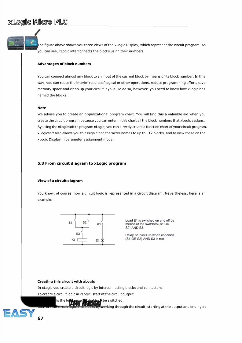
8/20/2019 XLogic User's Manual2
http://slidepdf.com/reader/full/xlogic-users-manual2 67/338
67
The figure above shows you three views of the xLogic Display, which represent the circuit program. As
you can see, xLogic interconnects the blocks using their numbers.
Advantages of block numbers
You can connect almost any block to an input of the current block by means of its block number. In this
way, you can reuse the interim results of logical or other operations, reduce programming effort, save
memory space and clean up your circuit layout. To do so, however, you need to know how xLogic has
named the blocks.
Note
We advise you to create an organizational program chart. You will find this a valuable aid when you
create the circuit program because you can enter in this chart all the block numbers that xLogic assigns.
By using the xLogicsoft to program xLogic, you can directly create a function chart of your circuit program.
xLogicsoft also allows you to assign eight character names to up to 512 blocks, and to view these on the
xLogic Display in parameter assignment mode.
5.3 From circuit diagram to xLogic program
View of a circuit diagram
You know, of course, how a circuit logic is represented in a circuit diagram. Nevertheless, here is an
example:
Creating this circuit with xLogic
In xLogic you create a circuit logic by interconnecting blocks and connectors:
To create a circuit logic in xLogic, start at the circuit output.
The output is the load or relay that is to be switched.
Convert the circuit logic into blocks by working through the circuit, starting at the output and ending at
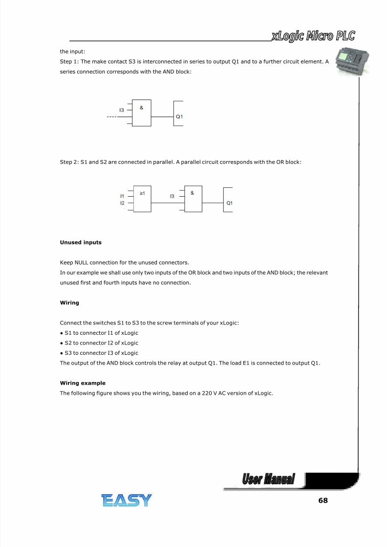
8/20/2019 XLogic User's Manual2
http://slidepdf.com/reader/full/xlogic-users-manual2 68/338
68
the input:
Step 1: The make contact S3 is interconnected in series to output Q1 and to a further circuit element. A
series connection corresponds with the AND block:
Step 2: S1 and S2 are connected in parallel. A parallel circuit corresponds with the OR block:
Unused inputs
Keep NULL connection for the unused connectors.
In our example we shall use only two inputs of the OR block and two inputs of the AND block; the relevant
unused first and fourth inputs have no connection.
Wiring
Connect the switches S1 to S3 to the screw terminals of your xLogic:
● S1 to connector I1 of xLogic
● S2 to connector I2 of xLogic
● S3 to connector I3 of xLogic
The output of the AND block controls the relay at output Q1. The load E1 is connected to output Q1.
Wiring example
The following figure shows you the wiring, based on a 220 V AC version of xLogic.
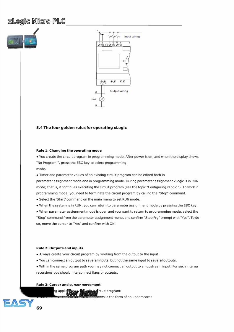
8/20/2019 XLogic User's Manual2
http://slidepdf.com/reader/full/xlogic-users-manual2 69/338
69
5.4 The four golden rules for operating xLogic
Rule 1: Changing the operating mode
● You create the circuit program in programming mode. After power is on, and when the display shows
"No Program ", press the ESC key to select programming
mode.
● Timer and parameter values of an existing circuit program can be edited both in
parameter assignment mode and in programming mode. During parameter assignment xLogic is in RUN
mode; that is, it continues executing the circuit program (see the topic "Configuring xLogic "). To work in
programming mode, you need to terminate the circuit program by calling the "Stop" command.
● Select the 'Start' command on the main menu to set RUN mode.
● When the system is in RUN, you can return to parameter assignment mode by pressing the ESC key.
● When parameter assignment mode is open and you want to return to programming mode, select the
"Stop" command from the parameter assignment menu, and confirm "Stop Prg" prompt with "Yes". To do
so, move the cursor to "Yes" and confirm with OK.
Rule 2: Outputs and inputs
● Always create your circuit program by working from the output to the input.
● You can connect an output to several inputs, but not the same input to several outputs.
● Within the same program path you may not connect an output to an upstream input. For such internal
recursions you should interconnect flags or outputs.
Rule 3: Cursor and cursor movement
The following applies when you edit a circuit program:
● You can move the cursor when it appears in the form of an underscore:

8/20/2019 XLogic User's Manual2
http://slidepdf.com/reader/full/xlogic-users-manual2 70/338
70
– Press , , or to move the cursor in the circuit program.
– Press OK to change to "Select connector/block".
– Press ESC to exit programming mode.
● You select a connector/block - when the cursor appears as a solid square:
– Press or to select a connector or a block.
– Confirm with OK.
– Press ESC to return to the previous step.
Rule 4: Planning
● Before you start to create a circuit program, you should either first create a design on paper or program
xLogic directly using xLogicsoft.
●xLogic can only save complete and faultless circuit programs.
5.5 Writing and starting the circuit program
After you have designed a circuit, you want to write it to your xLogic. The small example below shows
how to do this.
5.5.1 Selecting programming mode
You have connected xLogic to the power supply and switched it on. The display now shows you the
message:
Switch xLogic to programming mode by pressing ESC. This will take you to the main menu of xLogic:
The first character in the first line is the ">" cursor. Press and to move the ">" cursor up and down.
Move it to "Program.." and confirm with OK.xLogic opens the programming menu.
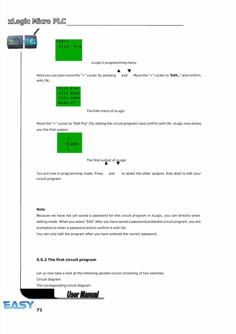
8/20/2019 XLogic User's Manual2
http://slidepdf.com/reader/full/xlogic-users-manual2 71/338
71
xLogic’s programming menu
Here you can also move the ">" cursor by pressing and . Move the ">" cursor to "Edit.." and confirm
with OK.
The Edit menu of xLogic
Move the ">" cursor to "Edit Prg" (for editing the circuit program) and confirm with OK. xLogic now shows
you the first output:
The first output of xLogic
You are now in programming mode. Press and to select the other outputs. Now start to edit your
circuit program.
Note
Because we have not yet saved a password for the circuit program in xLogic, you can directly enter
editing mode. When you select "Edit" after you have saved a password protected circuit program, you are
prompted to enter a password and to confirm it with OK.
You can only edit the program after you have entered the correct password.
5.5.2 The first circuit program
Let us now take a look at the following parallel circuit consisting of two switches.
Circuit diagram
The corresponding circuit diagram
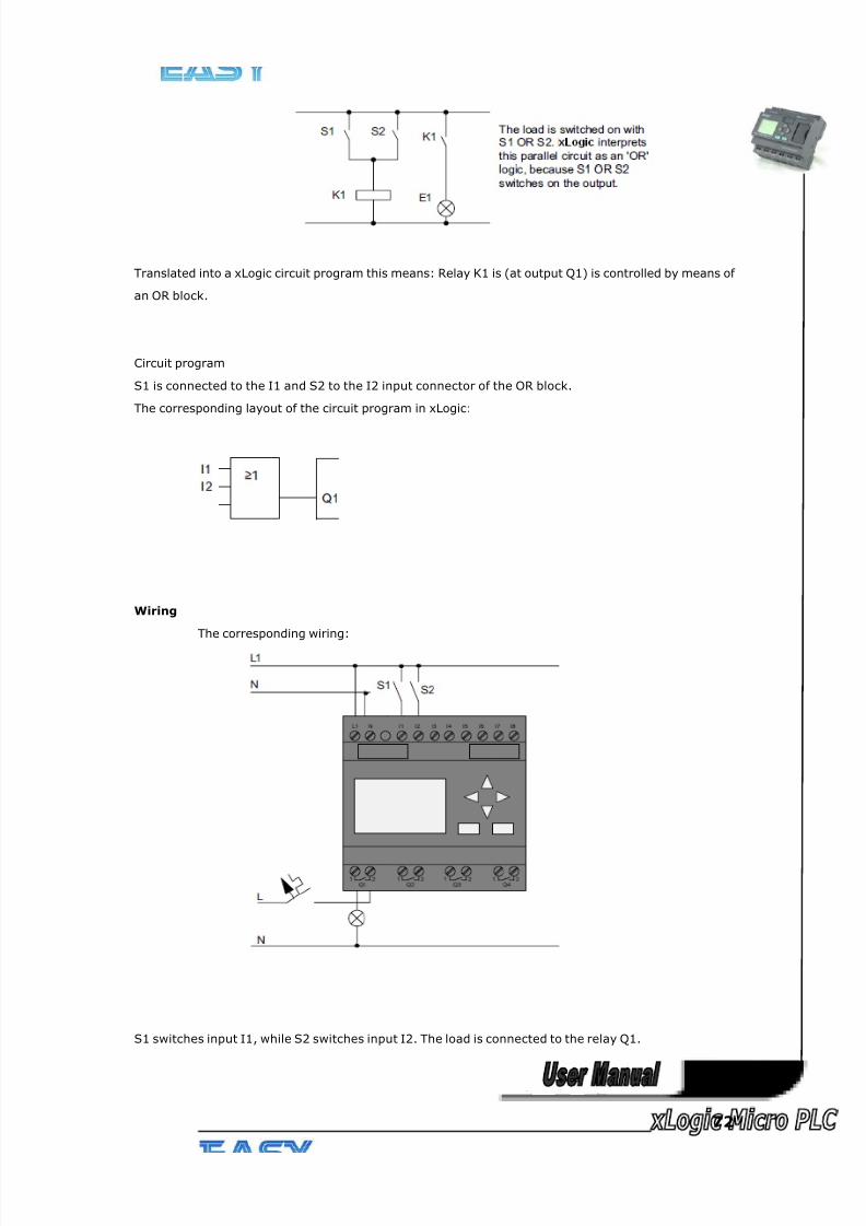
8/20/2019 XLogic User's Manual2
http://slidepdf.com/reader/full/xlogic-users-manual2 72/338
72
Translated into a xLogic circuit program this means: Relay K1 is (at output Q1) is controlled by means of
an OR block.
Circuit program
S1 is connected to the I1 and S2 to the I2 input connector of the OR block.
The corresponding layout of the circuit program in xLogic:
Wiring
The corresponding wiring:
S1 switches input I1, while S2 switches input I2. The load is connected to the relay Q1.
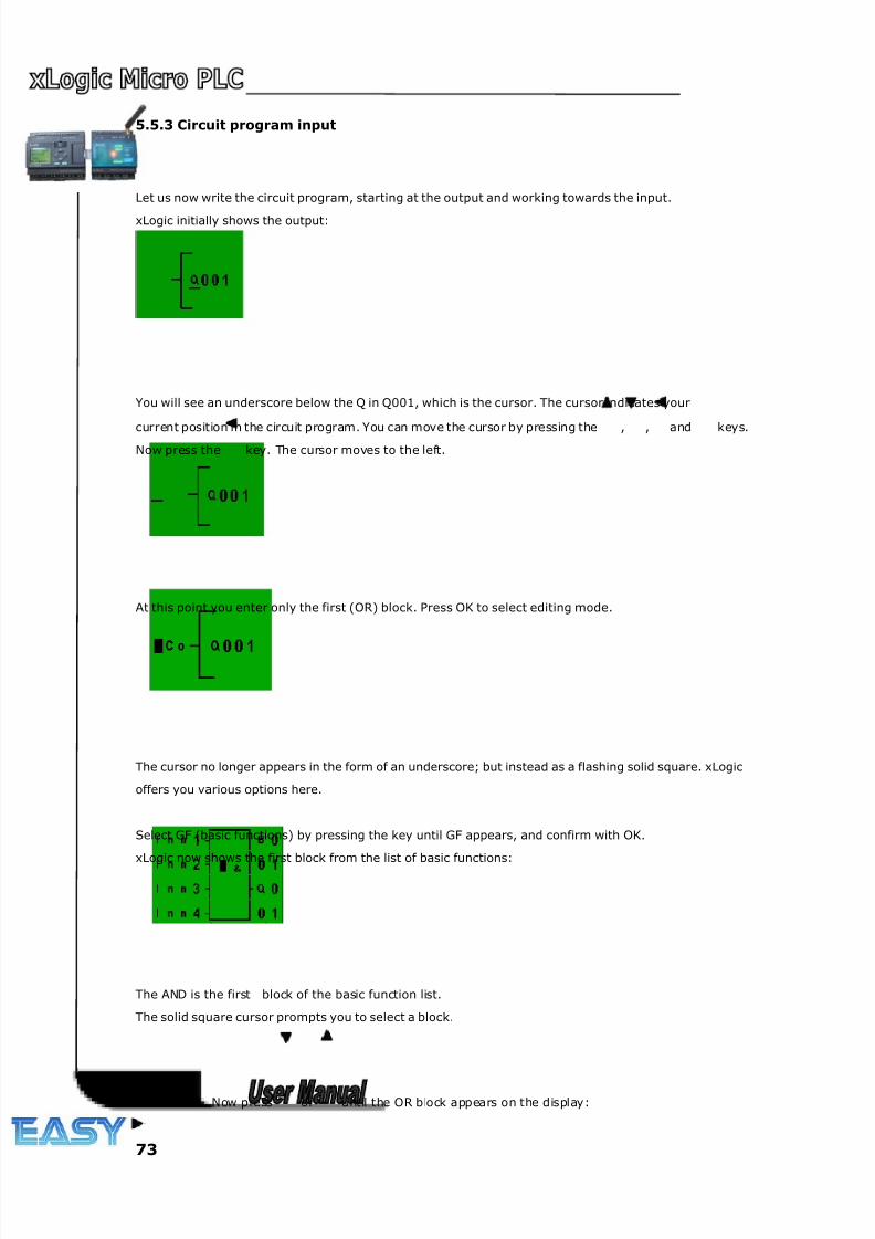
8/20/2019 XLogic User's Manual2
http://slidepdf.com/reader/full/xlogic-users-manual2 73/338
73
5.5.3 Circuit program input
Let us now write the circuit program, starting at the output and working towards the input.
xLogic initially shows the output:
You will see an underscore below the Q in Q001, which is the cursor. The cursor indicates your
current position in the circuit program. You can move the cursor by pressing the , , and keys.Now press the key. The cursor moves to the left.
At this point you enter only the first (OR) block. Press OK to select editing mode.
The cursor no longer appears in the form of an underscore; but instead as a flashing solid square. xLogic
offers you various options here.
Select GF (basic functions) by pressing the key until GF appears, and confirm with OK.
xLogic now shows the first block from the list of basic functions:
The AND is the first block of the basic function list.
The solid square cursor prompts you to select a block.
Now press or until the OR block appears on the display:
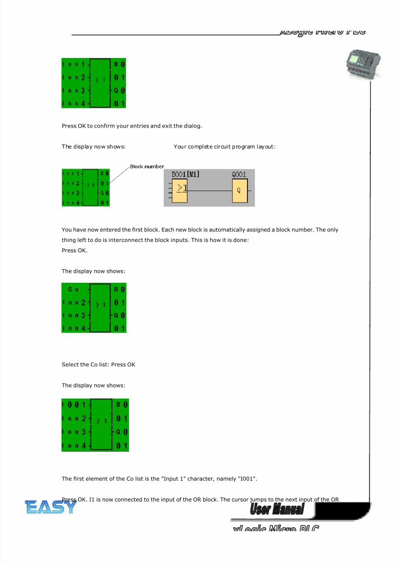
8/20/2019 XLogic User's Manual2
http://slidepdf.com/reader/full/xlogic-users-manual2 74/338
74
Press OK to confirm your entries and exit the dialog.
The display now shows: Your complete circuit program layout:
You have now entered the first block. Each new block is automatically assigned a block number. The only
thing left to do is interconnect the block inputs. This is how it is done:
Press OK.
The display now shows:
Select the Co list: Press OK
The display now shows:
The first element of the Co list is the "Input 1" character, namely "I001".
Press OK. I1 is now connected to the input of the OR block. The cursor jumps to the next input of the OR
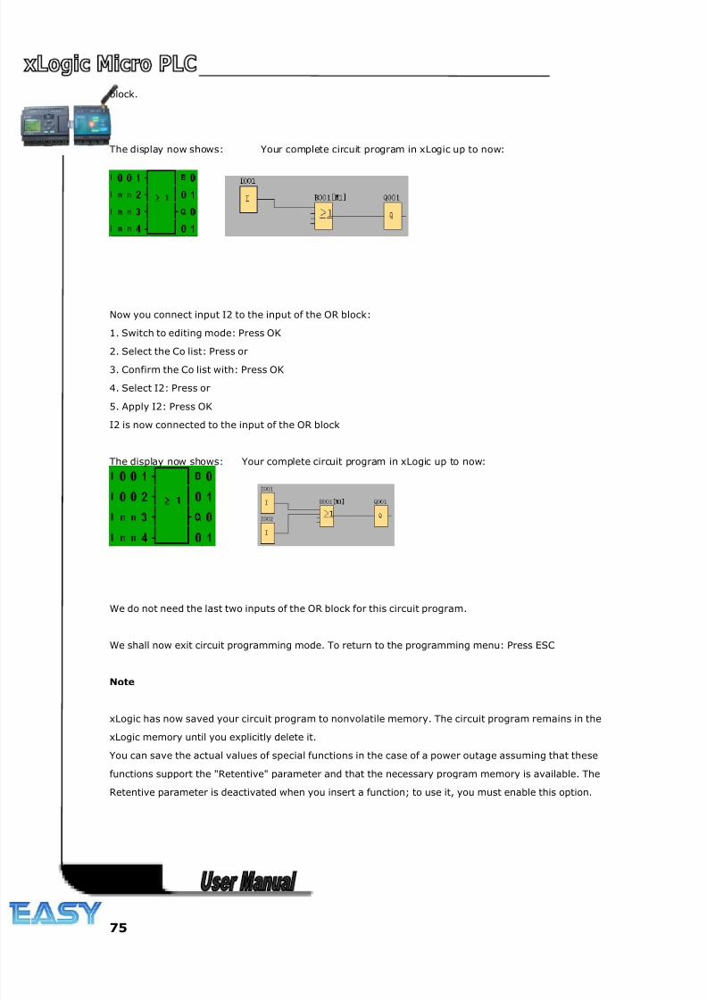
8/20/2019 XLogic User's Manual2
http://slidepdf.com/reader/full/xlogic-users-manual2 75/338
75
block.
The display now shows: Your complete circuit program in xLogic up to now:
Now you connect input I2 to the input of the OR block:
1. Switch to editing mode: Press OK
2. Select the Co list: Press or
3. Confirm the Co list with: Press OK
4. Select I2: Press or
5. Apply I2: Press OK
I2 is now connected to the input of the OR block
The display now shows: Your complete circuit program in xLogic up to now:
We do not need the last two inputs of the OR block for this circuit program.
We shall now exit circuit programming mode. To return to the programming menu: Press ESC
Note
xLogic has now saved your circuit program to nonvolatile memory. The circuit program remains in the
xLogic memory until you explicitly delete it.
You can save the actual values of special functions in the case of a power outage assuming that these
functions support the "Retentive" parameter and that the necessary program memory is available. The
Retentive parameter is deactivated when you insert a function; to use it, you must enable this option.
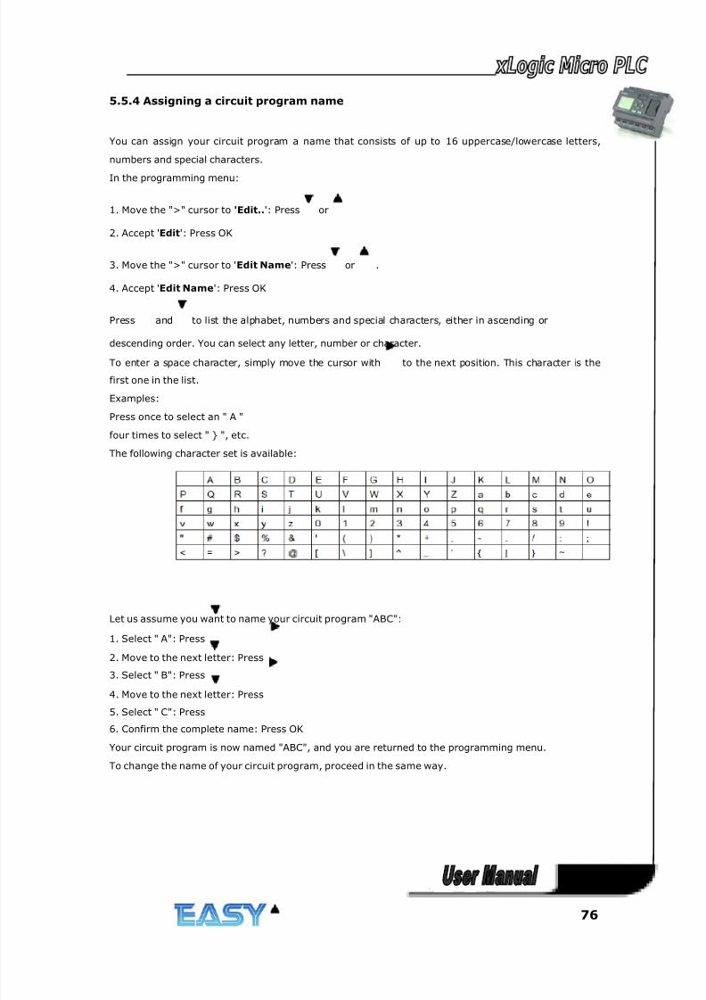
8/20/2019 XLogic User's Manual2
http://slidepdf.com/reader/full/xlogic-users-manual2 76/338
76
5.5.4 Assigning a circuit program name
You can assign your circuit program a name that consists of up to 16 uppercase/lowercase letters,
numbers and special characters.
In the programming menu:
1. Move the ">" cursor to 'Edit..': Press or
2. Accept 'Edit': Press OK
3. Move the ">" cursor to 'Edit Name': Press or .
4. Accept 'Edit Name': Press OK
Press and to list the alphabet, numbers and special characters, either in ascending or
descending order. You can select any letter, number or character.
To enter a space character, simply move the cursor with to the next position. This character is the
first one in the list.
Examples:
Press once to select an " A "
four times to select " } ", etc.
The following character set is available:
Let us assume you want to name your circuit program "ABC":
1. Select " A": Press
2. Move to the next letter: Press
3. Select " B": Press
4. Move to the next letter: Press
5. Select " C": Press
6. Confirm the complete name: Press OK
Your circuit program is now named "ABC", and you are returned to the programming menu.
To change the name of your circuit program, proceed in the same way.
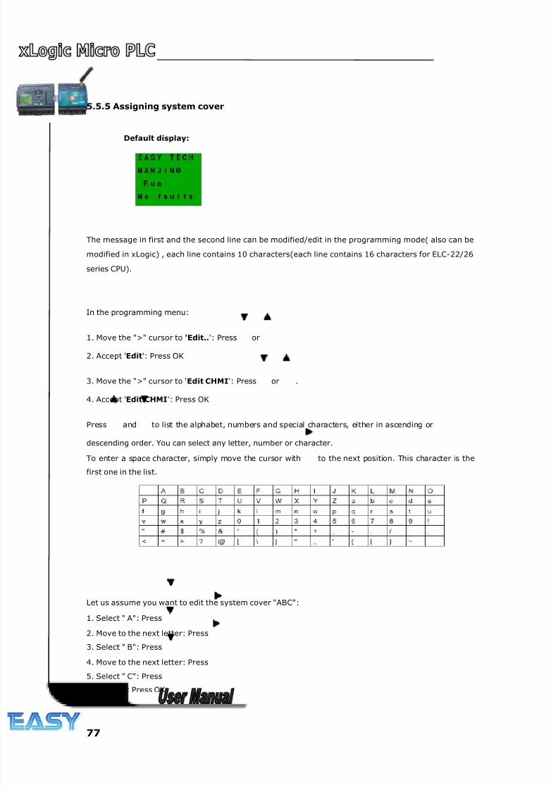
8/20/2019 XLogic User's Manual2
http://slidepdf.com/reader/full/xlogic-users-manual2 77/338
77
5.5.5 Assigning system cover
Default display:
The message in first and the second line can be modified/edit in the programming mode( also can be
modified in xLogic) , each line contains 10 characters(each line contains 16 characters for ELC-22/26
series CPU).
In the programming menu:
1. Move the ">" cursor to 'Edit..': Press or
2. Accept 'Edit': Press OK
3. Move the ">" cursor to 'Edit CHMI': Press or .
4. Accept 'Edit CHMI': Press OK
Press and to list the alphabet, numbers and special characters, either in ascending or
descending order. You can select any letter, number or character.
To enter a space character, simply move the cursor with to the next position. This character is the
first one in the list.
Let us assume you want to edit the system cover "ABC":
1. Select " A": Press
2. Move to the next letter: Press
3. Select " B": Press
4. Move to the next letter: Press
5. Select " C": Press
6. Confirm: Press OK
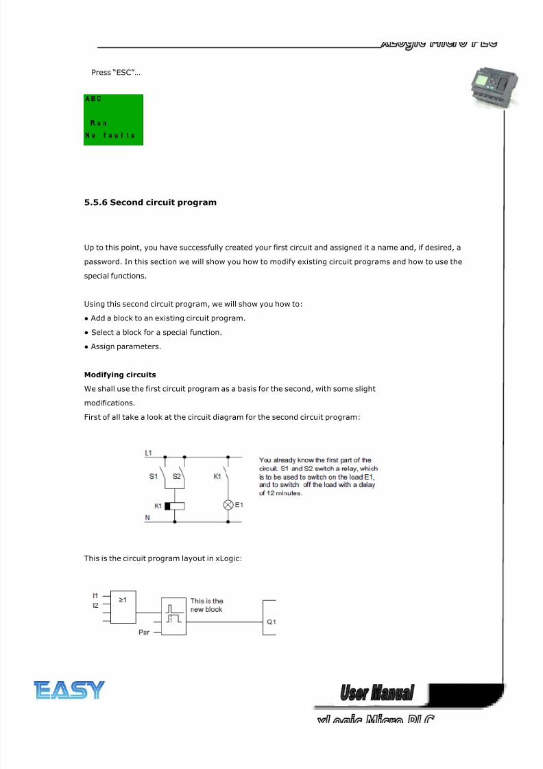
8/20/2019 XLogic User's Manual2
http://slidepdf.com/reader/full/xlogic-users-manual2 78/338
78
Press “ESC”…
5.5.6 Second circuit program
Up to this point, you have successfully created your first circuit and assigned it a name and, if desired, a
password. In this section we will show you how to modify existing circuit programs and how to use the
special functions.
Using this second circuit program, we will show you how to:
● Add a block to an existing circuit program.
● Select a block for a special function.
● Assign parameters.
Modifying circuits
We shall use the first circuit program as a basis for the second, with some slight
modifications.
First of all take a look at the circuit diagram for the second circuit program:
This is the circuit program layout in xLogic:
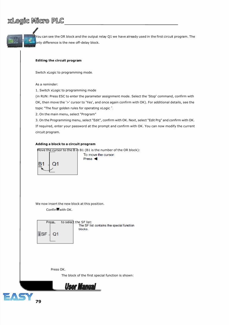
8/20/2019 XLogic User's Manual2
http://slidepdf.com/reader/full/xlogic-users-manual2 79/338
79
You can see the OR block and the output relay Q1 we have already used in the first circuit program. The
only difference is the new off-delay block.
Editing the circuit program
Switch xLogic to programming mode.
As a reminder:
1. Switch xLogic to programming mode
(in RUN: Press ESC to enter the parameter assignment mode. Select the 'Stop' command, confirm with
OK, then move the '>' cursor to 'Yes', and once again confirm with OK). For additional details, see the
topic "The four golden rules for operating xLogic ".
2. On the main menu, select "Program"
3. On the Programming menu, select "Edit", confirm with OK. Next, select "Edit Prg" and confirm with OK.
If required, enter your password at the prompt and confirm with OK. You can now modify the current
circuit program.
Adding a block to a circuit program
Move the cursor to the B in B1 (B1 is the number of the OR block):
We now insert the new block at this position.
Confirm with OK.
Press to select the SF list:
Press OK.
The block of the first special function is shown:
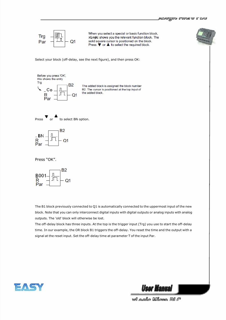
8/20/2019 XLogic User's Manual2
http://slidepdf.com/reader/full/xlogic-users-manual2 80/338
80
Select your block (off-delay, see the next figure), and then press OK:
Press or to select BN option.
Press “OK”.
The B1 block previously connected to Q1 is automatically connected to the uppermost input of the new
block. Note that you can only interconnect digital inputs with digital outputs or analog inputs with analog
outputs. The 'old' block will otherwise be lost.
The off-delay block has three inputs. At the top is the trigger input (Trg) you use to start the off-delay
time. In our example, the OR block B1 triggers the off-delay. You reset the time and the output with a
signal at the reset input. Set the off-delay time at parameter T of the input Par.
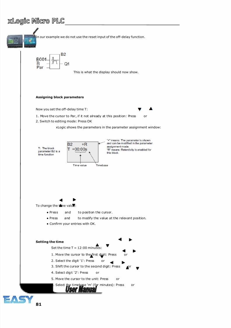
8/20/2019 XLogic User's Manual2
http://slidepdf.com/reader/full/xlogic-users-manual2 81/338
81
In our example we do not use the reset input of the off-delay function.
This is what the display should now show.
Assigning block parameters
Now you set the off-delay time T:
1. Move the cursor to Par, if it not already at this position: Press or
2. Switch to editing mode: Press OK
xLogic shows the parameters in the parameter assignment window:
To change the time value:
● Press and to position the cursor.
● Press and to modify the value at the relevant position.
● Confirm your entries with OK.
Setting the time
Set the time T = 12:00 minutes:
1. Move the cursor to the first digit: Press or
2. Select the digit '1': Press or
3. Shift the cursor to the second digit: Press or
4. Select digit '2': Press or
5. Move the cursor to the unit: Press or
6. Select the timebase 'm' (for minutes): Press or
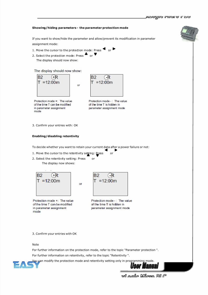
8/20/2019 XLogic User's Manual2
http://slidepdf.com/reader/full/xlogic-users-manual2 82/338
82
Showing/hiding parameters - the parameter protection mode
If you want to show/hide the parameter and allow/prevent its modification in parameter
assignment mode:
1. Move the cursor to the protection mode: Press or2. Select the protection mode: Press or
The display should now show:
3. Confirm your entries with: OK
Enabling/disabling retentivity
To decide whether you want to retain your current data after a power failure or not:
1. Move the cursor to the retentivity setting: Press or
2. Select the retentivity setting: Press or
The display now shows:
3. Confirm your entries with OK
Note
For further information on the protection mode, refer to the topic "Parameter protection ".
For further information on retentivity, refer to the topic "Retentivity ".
You can modify the protection mode and retentivity setting only in programming mode.
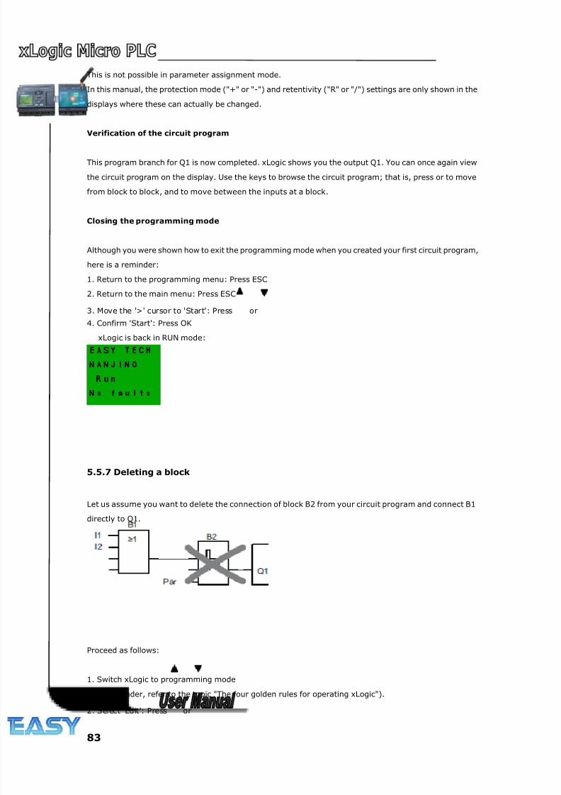
8/20/2019 XLogic User's Manual2
http://slidepdf.com/reader/full/xlogic-users-manual2 83/338
83
This is not possible in parameter assignment mode.
In this manual, the protection mode ("+" or "-") and retentivity ("R" or "/") settings are only shown in the
displays where these can actually be changed.
Verification of the circuit program
This program branch for Q1 is now completed. xLogic shows you the output Q1. You can once again view
the circuit program on the display. Use the keys to browse the circuit program; that is, press or to move
from block to block, and to move between the inputs at a block.
Closing the programming mode
Although you were shown how to exit the programming mode when you created your first circuit program,
here is a reminder:
1. Return to the programming menu: Press ESC
2. Return to the main menu: Press ESC
3. Move the '>' cursor to 'Start': Press or
4. Confirm 'Start': Press OK
xLogic is back in RUN mode:
5.5.7 Deleting a block
Let us assume you want to delete the connection of block B2 from your circuit program and connect B1
directly to Q1.
Proceed as follows:
1. Switch xLogic to programming mode
(as a reminder, refer to the topic "The four golden rules for operating xLogic").
2. Select 'Edit': Press or
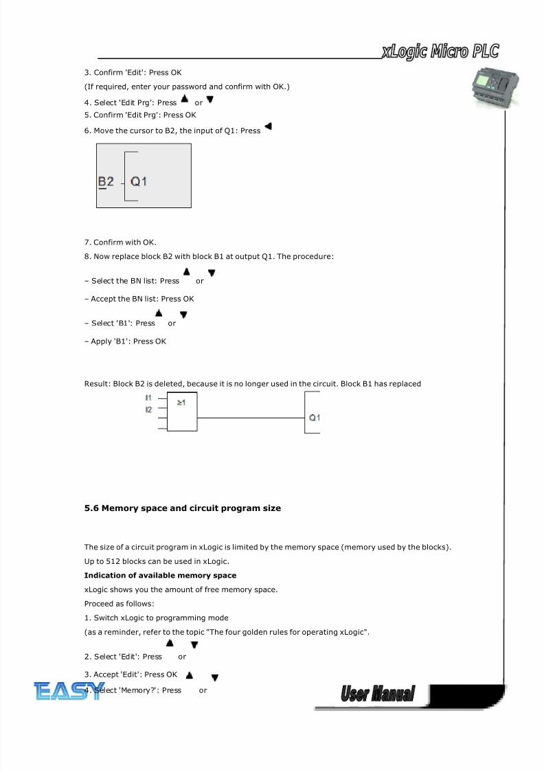
8/20/2019 XLogic User's Manual2
http://slidepdf.com/reader/full/xlogic-users-manual2 84/338
84
3. Confirm 'Edit': Press OK
(If required, enter your password and confirm with OK.)
4. Select 'Edit Prg': Press or
5. Confirm 'Edit Prg': Press OK
6. Move the cursor to B2, the input of Q1: Press
7. Confirm with OK.
8. Now replace block B2 with block B1 at output Q1. The procedure:
– Select the BN list: Press or
– Accept the BN list: Press OK
– Select 'B1': Press or
– Apply 'B1': Press OK
Result: Block B2 is deleted, because it is no longer used in the circuit. Block B1 has replaced
5.6 Memory space and circuit program size
The size of a circuit program in xLogic is limited by the memory space (memory used by the blocks).
Up to 512 blocks can be used in xLogic.
Indication of available memory space
xLogic shows you the amount of free memory space.
Proceed as follows:
1. Switch xLogic to programming mode
(as a reminder, refer to the topic "The four golden rules for operating xLogic".
2. Select 'Edit': Press or
3. Accept 'Edit': Press OK
4. Select 'Memory?': Press or
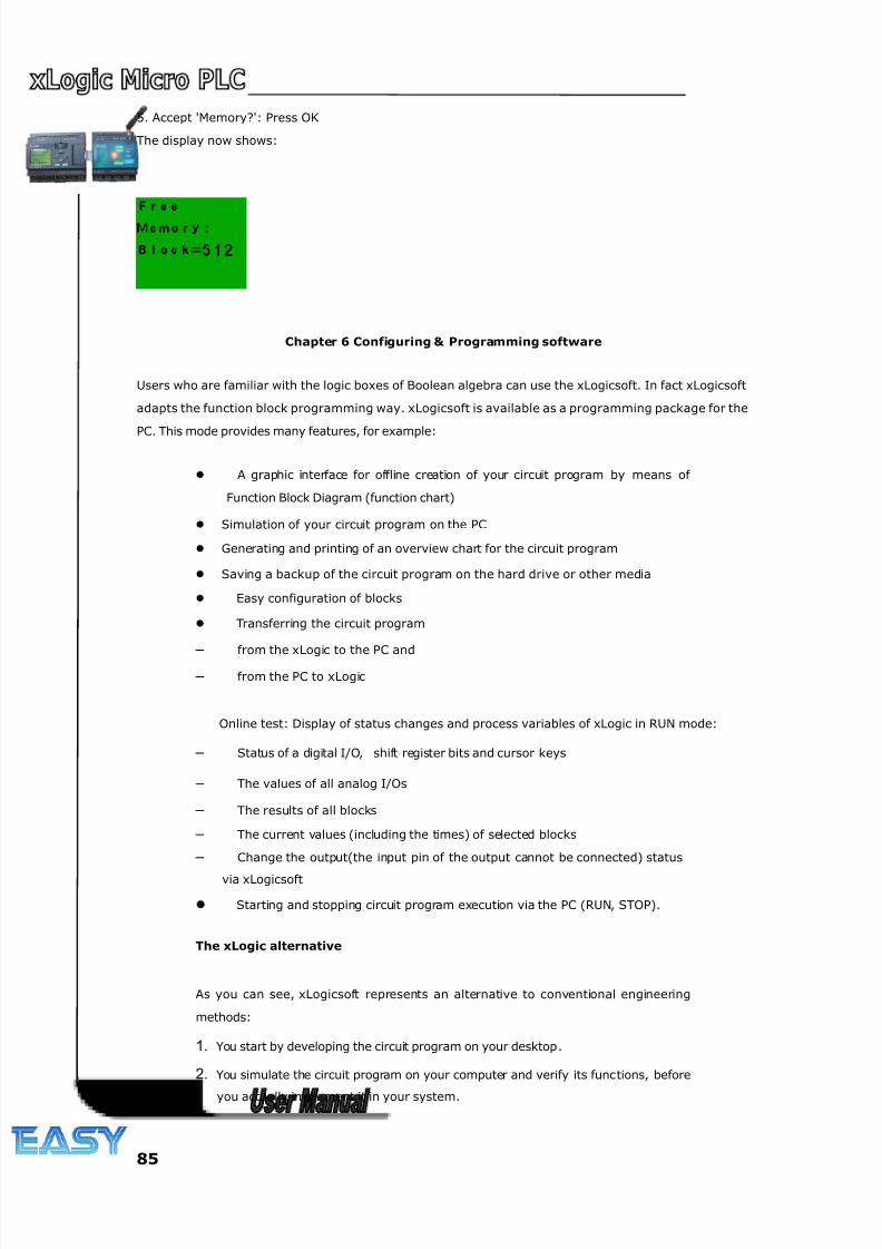
8/20/2019 XLogic User's Manual2
http://slidepdf.com/reader/full/xlogic-users-manual2 85/338
85
5. Accept 'Memory?': Press OK
The display now shows:
Chapter 6 Configuring & Programming software
Users who are familiar with the logic boxes of Boolean algebra can use the xLogicsoft. In fact xLogicsoft
adapts the function block programming way. xLogicsoft is available as a programming package for the
PC. This mode provides many features, for example:
A graphic interface for offline creation of your circuit program by means of
Function Block Diagram (function chart)
Simulation of your circuit program on the PC
Generating and printing of an overview chart for the circuit program
Saving a backup of the circuit program on the hard drive or other media
Easy configuration of blocks
Transferring the circuit program
– from the xLogic to the PC and
– from the PC to xLogic
Online test: Display of status changes and process variables of xLogic in RUN mode:
– Status of a digital I/O, shift register bits and cursor keys
– The values of all analog I/Os
– The results of all blocks
– The current values (including the times) of selected blocks
– Change the output(the input pin of the output cannot be connected) status
via xLogicsoft
Starting and stopping circuit program execution via the PC (RUN, STOP).
The xLogic alternative
As you can see, xLogicsoft represents an alternative to conventional engineering
methods:
1. You start by developing the circuit program on your desktop.
2. You simulate the circuit program on your computer and verify its functions, before
you actually implement it in your system.
8/20/2019 XLogic User's Manual2
http://slidepdf.com/reader/full/xlogic-users-manual2 86/338
86
3. You can add comments to the circuit program and create hard-copies.
4. You save a copy of your circuit program to the file system on your PC, to make it
directly available for any modifications.
5. It takes only a few key actions to download the circuit program to xLogic.
6. Under Simulate mode in xLogicsoft, you can study how to program via the panel
key.
6.1 xLogic Functions
ELC series adapts programming methods by means of function blocks. A total of 9 general function blocks,
37 special function blocks, and 11 input & output function blocks are configured. And each block can
achieve a specific control function independently, e.g. TOND, TOFD, SBPL, TBPL, SCHD, etc. As several
blocks are linked up in a specific way, relatively complicated control functions can be performed.
Programming with function blocks is simpler and better appreciated than the conventional PLC
instruction programming.
The following types of operator for xLogic function blocks are available for options:
6.2 General Input & Output functions
6.2.1 Inputs
Input blocks represent the input terminals of xLogic. Up to 8 digital inputs are available to you.
In your block configuration, you can assign an input block a new input terminal, if this terminal
is not already used in the circuit program.
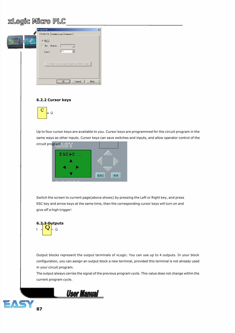
8/20/2019 XLogic User's Manual2
http://slidepdf.com/reader/full/xlogic-users-manual2 87/338
87
6.2.2 Cursor keys
Up to four cursor keys are available to you. Cursor keys are programmed for the circuit program in the
same ways as other inputs. Cursor keys can save switches and inputs, and allow operator control of the
circuit program.
Switch the screen to current page(above shows) by pressing the Left or Right key, and press
ESC key and arrow keys at the same time, then the corresponding cursor keys will turn on and
give off a high trigger!
6.2.3 Outputs
Output blocks represent the output terminals of xLogic. You can use up to 4 outputs. In your block
configuration, you can assign an output block a new terminal, provided this terminal is not already used
in your circuit program.
The output always carries the signal of the previous program cycle. This value does not change within the
current program cycle.
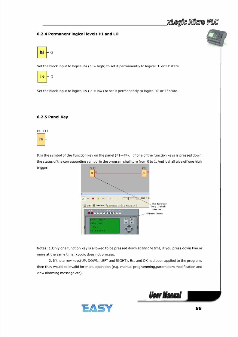
8/20/2019 XLogic User's Manual2
http://slidepdf.com/reader/full/xlogic-users-manual2 88/338
88
6.2.4 Permanent logical levels HI and LO
Set the block input to logical hi (hi = high) to set it permanently to logical '1' or 'H' state.
Set the block input to logical lo (lo = low) to set it permanently to logical '0' or 'L' state.
6.2.5 Panel Key
It is the symbol of the Function key on the panel (F1—F4). If one of the function keys is pressed down,
the status of the corresponding symbol in the program shall turn from 0 to 1. And it shall give off one high
trigger.
Notes: 1.Only one function key is allowed to be pressed down at any one time, if you press down two or
more at the same time, xLogic does not process.
2. If the arrow keys(UP, DOWN, LEFT and RIGHT), Esc and OK had been applied to the program,
then they would be invalid for menu operation (e.g. manual programming,parameters modification and
view alarming message etc).
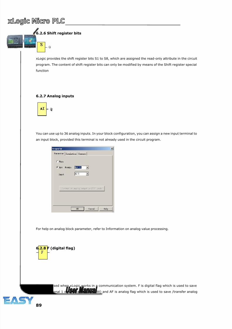
8/20/2019 XLogic User's Manual2
http://slidepdf.com/reader/full/xlogic-users-manual2 89/338
89
6.2.6 Shift register bits
xLogic provides the shift register bits S1 to S8, which are assigned the read-only attribute in the circuit
program. The content of shift register bits can only be modified by means of the Shift register special
function
6.2.7 Analog inputs
You can use up to 36 analog inputs. In your block configuration, you can assign a new input terminal to
an input block, provided this terminal is not already used in the circuit program.
For help on analog block parameter, refer to Information on analog value processing.
6.2.8 F (digital flag)
Flags are used when xLogic works in a communication system. F is digital flag which is used to save
/transfer signal 1 or 0(data format is Bit) and AF is analog flag which is used to save /transfer analog
8/20/2019 XLogic User's Manual2
http://slidepdf.com/reader/full/xlogic-users-manual2 90/338
90
values (data format is Signed short) between the master and slave devices. Both of the flags
(digital/analog) are up to 64 can be used when programming. In your block configuration, you can assign
a new number to the flag, provided this flag number does not already exist in your circuit program.
The output always carries the signal of the previous program cycle. This value does not change if the
communication has failed.
Startup flag: F8
The F8 flag is set in the first cycle of the user program and can thus be used in your circuit program as
a startup flag. It is reset after the first program execution cycle.
In the subsequent cycles, the F8 flag reacts in the same way as the F1 to F64 flags.
Backlight flags: F64
The F64 flag controls the backlight of the xLogic onboard display.
You can use the outputs of timers, message texts, or other function blocks to activate the backlight flags.
To enable multiple conditions to control the backlight of the devices, you can use multiple function blocks
in parallel or in sequence.
Notes: 1.The address of “ F“ can be found in the modbus communication protocol file . the F block figure
must have the input pin in the xLogic showing.
1. Keep the input pin of F NULL(do not connect with other blocks) ,if you want to use the write property.
6.2.9 AF (Analog flag)
Flags are used when xLogic works in a communication system. F is digital flag which is used to save
/transfer signal 1 or 0(data format is Bit) and AF is analog flag which is used to save /transfer analog
values (data format is Signed short) between the master and slave devices. Both of flags (digital/analog)
are up to 64 for xLogic CPU can be used when programming. In your block configuration, you can assign
a new number to the analog flag, provided this flag number does not already exist in your circuit
program.
The output always carries the signal of the previous program cycle. This value does not change if the
communication were failed.
Notes: 1.The address of “AF“ can be found in the modbus communication protocol file .
2.Keep the input pin of AF NULL(do not connect with other blocks) ,if you want to use the write
property.
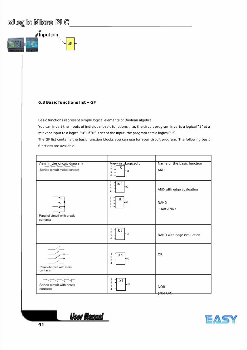
8/20/2019 XLogic User's Manual2
http://slidepdf.com/reader/full/xlogic-users-manual2 91/338
91
6.3 Basic functions list – GF
Basic functions represent simple logical elements of Boolean algebra.
You can invert the inputs of individual basic functions , i.e. the circuit program inverts a logical “1” at a
relevant input to a logical “0”; if “0” is set at the input, the program sets a logical “1”.
The GF list contains the basic function blocks you can use for your circuit program. The following basic
functions are available:
View in the circuit diagram View in xLogicsoft Name of the basic function
AND
AND with edge evaluation
NAND
(Not AND)
NAND with edge evaluation
OR
NOR
(Not OR)
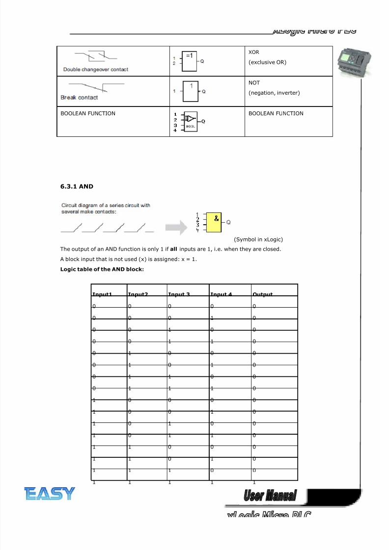
8/20/2019 XLogic User's Manual2
http://slidepdf.com/reader/full/xlogic-users-manual2 92/338
92
XOR
(exclusive OR)
NOT
(negation, inverter)
BOOLEAN FUNCTION BOOLEAN FUNCTION
6.3.1 AND
(Symbol in xLogic)
The output of an AND function is only 1 if all inputs are 1, i.e. when they are closed.
A block input that is not used (x) is assigned: x = 1.
Logic table of the AND block:
Input1 Input2 Input 3 Input 4 Output
0 0 0 0 0
0 0 0 1 0
0 0 1 0 0
0 0 1 1 0
0 1 0 0 0
0 1 0 1 0
0 1 1 0 0
0 1 1 1 0
1 0 0 0 0
1 0 0 1 0
1 0 1 0 0
1 0 1 1 0
1 1 0 0 0
1 1 0 1 0
1 1 1 0 0
1 1 1 1 1
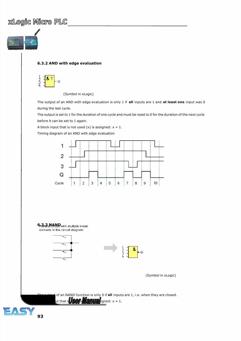
8/20/2019 XLogic User's Manual2
http://slidepdf.com/reader/full/xlogic-users-manual2 93/338
93
6.3.2 AND with edge evaluation
(Symbol in xLogic)
The output of an AND with edge evaluation is only 1 if all inputs are 1 and at least one input was 0
during the last cycle.
The output is set to 1 for the duration of one cycle and must be reset to 0 for the duration of the next cycle
before it can be set to 1 again.
A block input that is not used (x) is assigned: x = 1.
Timing diagram of an AND with edge evaluation
6.3.3 NAND
(Symbol in xLogic)
The output of an NAND function is only 0 if all inputs are 1, i.e. when they are closed.
A block input that is not used (x) is assigned: x = 1.
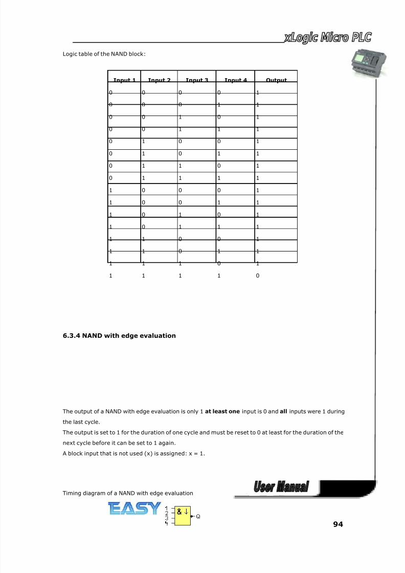
8/20/2019 XLogic User's Manual2
http://slidepdf.com/reader/full/xlogic-users-manual2 94/338
94
Logic table of the NAND block:
Input 1 Input 2 Input 3 Input 4 Output
0 0 0 0 1
0 0 0 1 1
0 0 1 0 1
0 0 1 1 1
0 1 0 0 1
0 1 0 1 1
0 1 1 0 1
0 1 1 1 1
1 0 0 0 1
1 0 0 1 1
1 0 1 0 1
1 0 1 1 1
1 1 0 0 1
1 1 0 1 1
1 1 1 0 1
1 1 1 1 0
6.3.4 NAND with edge evaluation
The output of a NAND with edge evaluation is only 1 at least one input is 0 and all inputs were 1 during
the last cycle.
The output is set to 1 for the duration of one cycle and must be reset to 0 at least for the duration of the
next cycle before it can be set to 1 again.
A block input that is not used (x) is assigned: x = 1.
Timing diagram of a NAND with edge evaluation
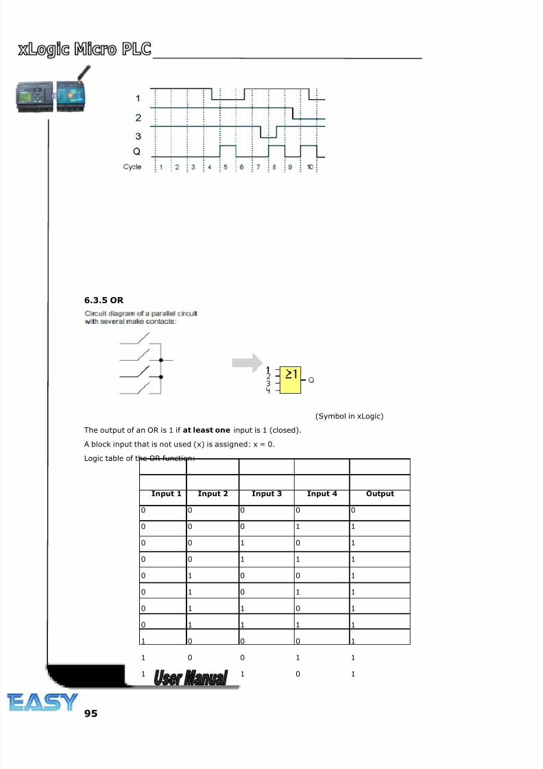
8/20/2019 XLogic User's Manual2
http://slidepdf.com/reader/full/xlogic-users-manual2 95/338
95
6.3.5 OR
(Symbol in xLogic)
The output of an OR is 1 if at least one input is 1 (closed).
A block input that is not used (x) is assigned: x = 0.
Logic table of the OR function:
Input 1 Input 2 Input 3 Input 4 Output
0 0 0 0 0
0 0 0 1 1
0 0 1 0 1
0 0 1 1 1
0 1 0 0 1
0 1 0 1 1
0 1 1 0 1
0 1 1 1 1
1 0 0 0 1
1 0 0 1 1
1 0 1 0 1
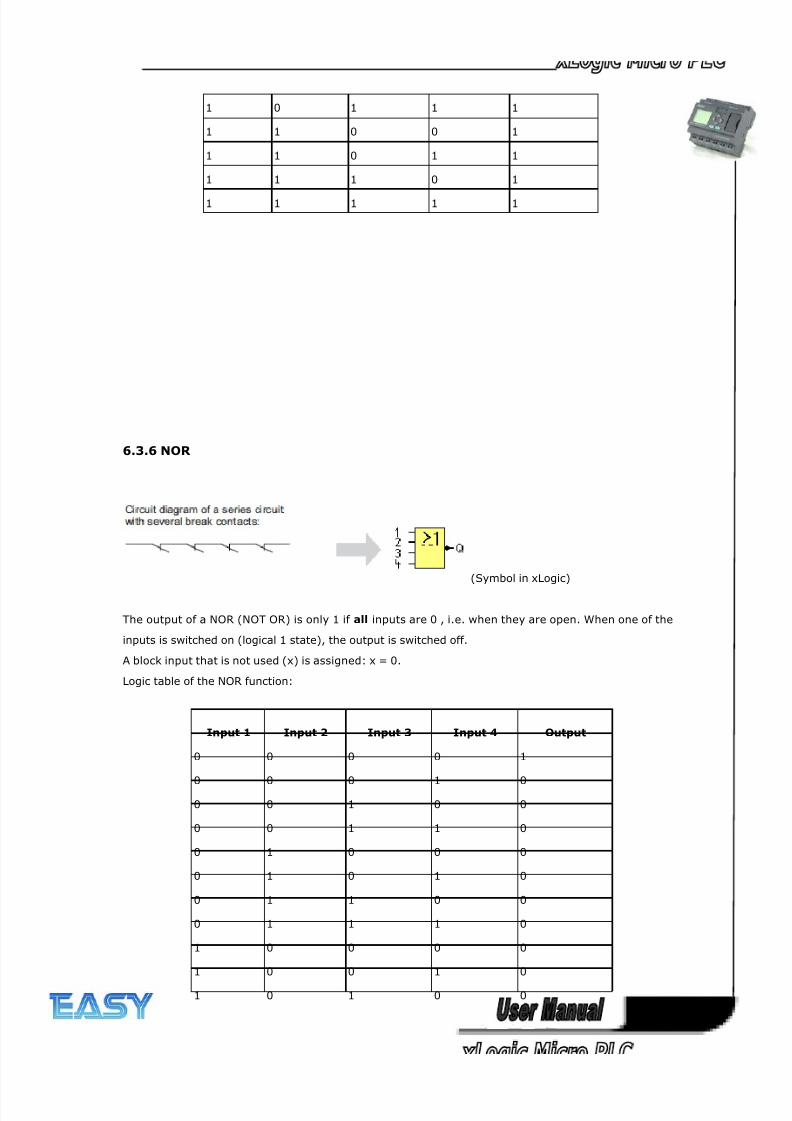
8/20/2019 XLogic User's Manual2
http://slidepdf.com/reader/full/xlogic-users-manual2 96/338
96
1 0 1 1 1
1 1 0 0 1
1 1 0 1 1
1 1 1 0 1
1 1 1 1 1
6.3.6 NOR
(Symbol in xLogic)
The output of a NOR (NOT OR) is only 1 if all inputs are 0 , i.e. when they are open. When one of the
inputs is switched on (logical 1 state), the output is switched off.
A block input that is not used (x) is assigned: x = 0.
Logic table of the NOR function:
Input 1 Input 2 Input 3 Input 4 Output
0 0 0 0 1
0 0 0 1 0
0 0 1 0 0
0 0 1 1 0
0 1 0 0 0
0 1 0 1 0
0 1 1 0 0
0 1 1 1 0
1 0 0 0 0
1 0 0 1 0
1 0 1 0 0
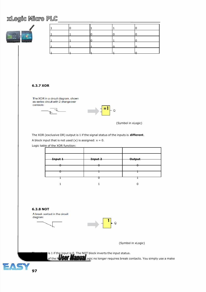
8/20/2019 XLogic User's Manual2
http://slidepdf.com/reader/full/xlogic-users-manual2 97/338
97
1 0 1 1 0
1 1 0 0 0
1 1 0 1 0
1 1 1 0 0
1 1 1 1 0
6.3.7 XOR
(Symbol in xLogic)
The XOR (exclusive OR) output is 1 if the signal status of the inputs is different.
A block input that is not used (x) is assigned: x = 0.
Logic table of the XOR function:
Input 1 Input 2 Output
0 0 0
0 1 1
1 0 1
1 1 0
6.3.8 NOT
(Symbol in xLogic)
The output is 1 if the input is 0. The NOT block inverts the input status.
Advantage of the NOT, for example: xLogic no longer requires break contacts. You simply use a make
8/20/2019 XLogic User's Manual2
http://slidepdf.com/reader/full/xlogic-users-manual2 98/338
98
contact and convert it into a break contact with the help of the NOT function.
Logic table of the NOT function:
Input 1 Output
0 1
1 0
6.3.9 Boolean Function
The BOOLEAN function gives the value of the output according to the combination of inputs.
The function has four inputs, and therefore 16 combinations. These combinations can be found in a truth
table; for each of these, the output value can be adjusted. The number of configurable combinations
depends on the number of inputs connected to the function.
Non-connected inputs are set to 0.
The following diagram shows an example of part of the Boolean function truth table:
Parameters
Having connected at least one input, you can configure the value of the output in the truth table, in the
Parameters window.
The output values can be 0 for the Inactive state, and 1 for the Active state(Double click to change the
0 or 1 ).
By selecting the Output ON if result is TRUE option, the output takes the value configured in the truth
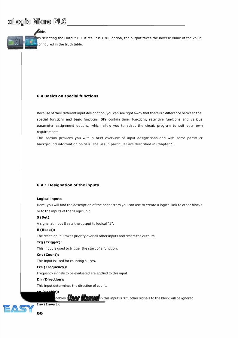
8/20/2019 XLogic User's Manual2
http://slidepdf.com/reader/full/xlogic-users-manual2 99/338
99
table.
By selecting the Output OFF if result is TRUE option, the output takes the inverse value of the value
configured in the truth table.
6.4 Basics on special functions
Because of their different input designation, you can see right away that there is a difference between the
special functions and basic functions. SFs contain timer functions, retentive functions and various
parameter assignment options, which allow you to adapt the circuit program to suit your own
requirements.
This section provides you with a brief overview of input designations and with some particular
background information on SFs. The SFs in particular are described in Chapter7.5
6.4.1 Designation of the inputs
Logical inputs
Here, you will find the description of the connectors you can use to create a logical link to other blocks
or to the inputs of the xLogic unit.
S (Set):
A signal at input S sets the output to logical “1”.
R (Reset):
The reset input R takes priority over all other inputs and resets the outputs.
Trg (Trigger):
This input is used to trigger the start of a function.
Cnt (Count):
This input is used for counting pulses.
Fre (Frequency):
Frequency signals to be evaluated are applied to this input.
Dir (Direction):
This input determines the direction of count.
En (Enable):
This input enables a block function. When this input is “0”, other signals to the block will be ignored.
Inv (Invert):
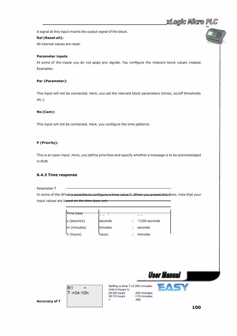
8/20/2019 XLogic User's Manual2
http://slidepdf.com/reader/full/xlogic-users-manual2 100/338
100
A signal at this input inverts the output signal of the block.
Ral (Reset all):
All internal values are reset.
Parameter inputs
At some of the inputs you do not apply any signals. You configure the relevant block values instead.
Examples:
Par (Parameter):
This input will not be connected. Here, you set the relevant block parameters (times, on/off thresholds
etc.).
No (Cam):
This input will not be connected. Here, you configure the time patterns.
P (Priority):
This is an open input. Here, you define priorities and specify whether a message is to be acknowledged
in RUN.
6.4.2 Time response
Parameter T
In some of the SFs it is possible to configure a time value T. When you preset this time, note that your
input values are based on the time base set:
Time base _ _ : _ _
s (seconds) seconds : 1 /100 seconds
m (minutes) minutes : seconds
h (hours) hours : minutes
Accuracy of T
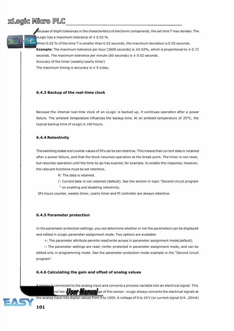
8/20/2019 XLogic User's Manual2
http://slidepdf.com/reader/full/xlogic-users-manual2 101/338
101
Because of slight tolerances in the characteristics of electronic components, the set time T may deviate. The
xLogic has a maximum tolerance of ± 0.02 %.
When 0.02 % of the time T is smaller than 0.02 seconds, the maximum deviation is 0.02 seconds.
Example: The maximum tolerance per hour (3600 seconds) is ±0.02%, which is proportional to ± 0.72
seconds. The maximum tolerance per minute (60 seconds) is ± 0.02 seconds.
Accuracy of the timer (weekly/yearly timer)
The maximum timing in accuracy is ± 5 s/day.
6.4.3 Backup of the real-time clock
Because the internal real-time clock of an xLogic is backed up, it continues operation after a power
failure. The ambient temperature influences the backup time. At an ambient temperature of 25°C, the
typical backup time of xLogic is 100 hours.
6.4.4 Retentivity
The switching states and counter values of SFs can be set retentive. This means that current data is retained
after a power failure, and that the block resumes operation at the break point. The timer is not reset,
but resumes operation until the time-to-go has expired, for example, to enable this response, however,
the relevant functions must be set retentive.
R: The data is retained.
/: Current data is not retained (default). See the section in topic "Second circuit program
" on enabling and disabling retentivity.
SFs hours counter, weekly timer, yearly timer and PI controller are always retentive.
6.4.5 Parameter protection
In the parameter protection settings, you can determine whether or not the parameters can be displayed
and edited in xLogic parameter assignment mode. Two options are available:
+: The parameter attribute permits read/write access in parameter assignment mode(default).
-: The parameter settings are read–/write–protected in parameter assignment mode, and can be
edited only in programming mode. See the parameter protection mode example in the "Second circuit
program".
6.4.6 Calculating the gain and offset of analog values
A sensor is connected to the analog input and converts a process variable into an electrical signal. This
value of signal lies within the typical range of this sensor. xLogic always converts the electrical signals at
the analog input into digital values from 0 to 1000. A voltage of 0 to 10 V (or current signal 0/4…20mA)
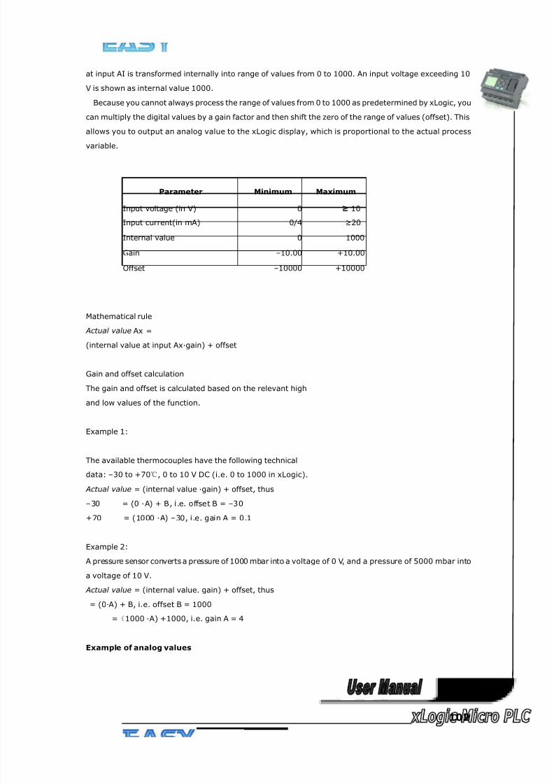
8/20/2019 XLogic User's Manual2
http://slidepdf.com/reader/full/xlogic-users-manual2 102/338
102
at input AI is transformed internally into range of values from 0 to 1000. An input voltage exceeding 10
V is shown as internal value 1000.
Because you cannot always process the range of values from 0 to 1000 as predetermined by xLogic, you
can multiply the digital values by a gain factor and then shift the zero of the range of values (offset). This
allows you to output an analog value to the xLogic display, which is proportional to the actual process
variable.
Parameter Minimum Maximum
Input voltage (in V) 0 ≥ 10
Input current(in mA) 0/4 ≥20
Internal value 0 1000
Gain –10.00 +10.00
Offset –10000 +10000
Mathematical rule
Actual value Ax =
(internal value at input Ax·gain) + offset
Gain and offset calculation
The gain and offset is calculated based on the relevant high
and low values of the function.
Example 1:
The available thermocouples have the following technical
data: –30 to +70℃, 0 to 10 V DC (i.e. 0 to 1000 in xLogic).
Actual value = (internal value ·gain) + offset, thus
–30 = (0 ·A) + B, i.e. offset B = –30
+70 = (1000 ·A) –30, i.e. gain A = 0.1
Example 2:A pressure sensor converts a pressure of 1000 mbar into a voltage of 0 V, and a pressure of 5000 mbar into
a voltage of 10 V.
Actual value = (internal value. gain) + offset, thus
= (0·A) + B, i.e. offset B = 1000
=(1000 ·A) +1000, i.e. gain A = 4
Example of analog values
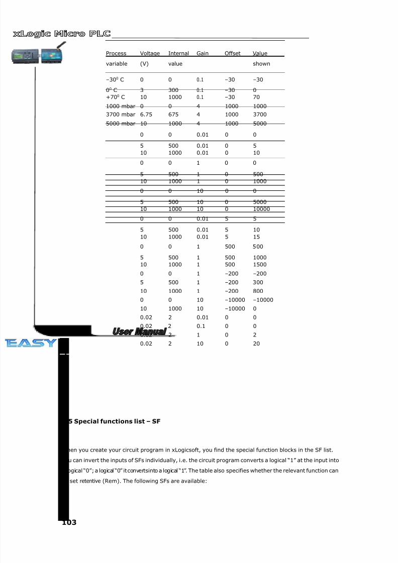
8/20/2019 XLogic User's Manual2
http://slidepdf.com/reader/full/xlogic-users-manual2 103/338
103
Process
variable
Voltage
(V)
Internal
value
Gain Offset Value
shown
–300 C 0 0 0.1 –30 –30
00 C 3 300 0.1 –30 0
+700
C 10 1000 0.1 –30 701000 mbar 0 0 4 1000 1000
3700 mbar 6.75 675 4 1000 3700
5000 mbar 10 1000 4 1000 5000
0 0 0.01 0 0
5 500 0.01 0 5
10 1000 0.01 0 10
0 0 1 0 0
5 500 1 0 500
10 1000 1 0 1000
0 0 10 0 0
5 500 10 0 5000
10 1000 10 0 10000
0 0 0.01 5 5
5 500 0.01 5 10
10 1000 0.01 5 15
0 0 1 500 500
5 500 1 500 1000
10 1000 1 500 1500
0 0 1 –200 –200
5 500 1 –200 300
10 1000 1 –200 800
0 0 10 –10000 –10000
10 1000 10 –10000 0
0.02 2 0.01 0 0
0.02 2 0.1 0 0
0.02 2 1 0 2
0.02 2 10 0 20
6.5 Special functions list – SF
When you create your circuit program in xLogicsoft, you find the special function blocks in the SF list.
You can invert the inputs of SFs individually, i.e. the circuit program converts a logical “1” at the input into
a logical “0”; a logical “0” itconvertsinto a logical “1”. The table also specifies whether the relevant function can
be set retentive (Rem). The following SFs are available:
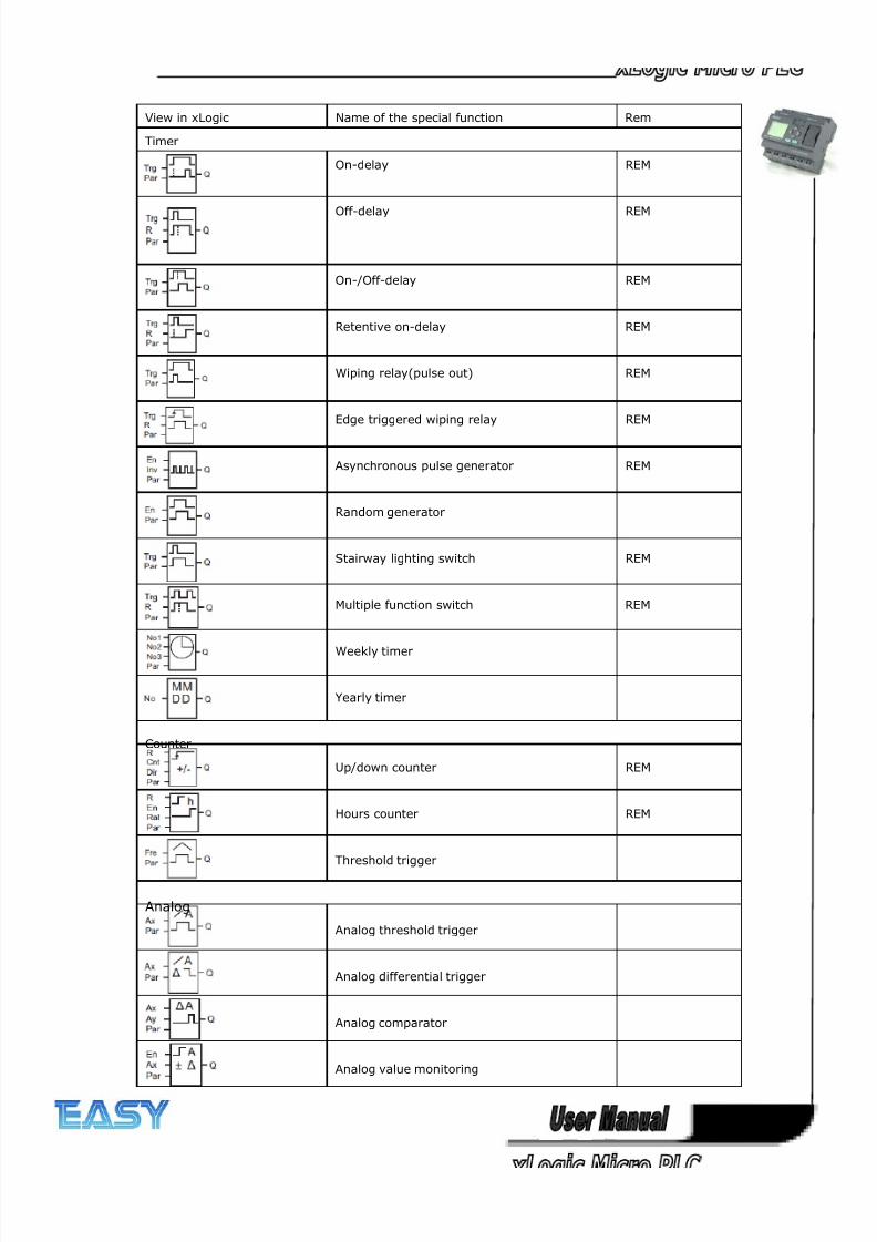
8/20/2019 XLogic User's Manual2
http://slidepdf.com/reader/full/xlogic-users-manual2 104/338
104
View in xLogic Name of the special function Rem
Timer
On-delay REM
Off-delay REM
On-/Off-delay REM
Retentive on-delay REM
Wiping relay(pulse out) REM
Edge triggered wiping relay REM
Asynchronous pulse generator REM
Random generator
Stairway lighting switch REM
Multiple function switch REM
Weekly timer
Yearly timer
Counter
Up/down counter REM
Hours counter REM
Threshold trigger
Analog
Analog threshold trigger
Analog differential trigger
Analog comparator
Analog value monitoring
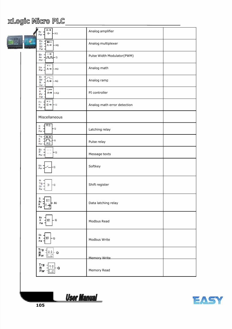
8/20/2019 XLogic User's Manual2
http://slidepdf.com/reader/full/xlogic-users-manual2 105/338
105
Analog amplifier
Analog multiplexer
Pulse Width Modulator(PWM)
Analog math
Analog ramp
PI controller
Analog math error detection
Miscellaneous
Latching relay
Pulse relay
Message texts
Softkey
Shift register
Data latching relay
Modbus Read
Modbus Write
Memory Write
Memory Read
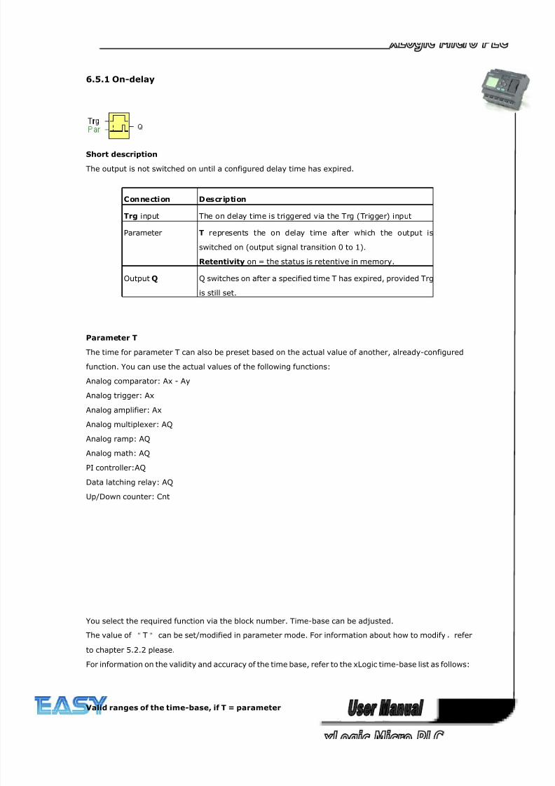
8/20/2019 XLogic User's Manual2
http://slidepdf.com/reader/full/xlogic-users-manual2 106/338
106
6.5.1 On-delay
Short description
The output is not switched on until a configured delay time has expired.
Connection Description
Trg input The on delay time is triggered via the Trg (Trigger) input
Parameter T represents the on delay time after which the output is
switched on (output signal transition 0 to 1).
Retentivity on = the status is retentive in memory.
Output Q Q switches on after a specified time T has expired, provided Trg
is still set.
Parameter T
The time for parameter T can also be preset based on the actual value of another, already-configured
function. You can use the actual values of the following functions:
Analog comparator: Ax - Ay
Analog trigger: Ax
Analog amplifier: AxAnalog multiplexer: AQ
Analog ramp: AQ
Analog math: AQ
PI controller:AQ
Data latching relay: AQ
Up/Down counter: Cnt
You select the required function via the block number. Time-base can be adjusted.
The value of "T" can be set/modified in parameter mode. For information about how to modify,refer
to chapter 5.2.2 please.
For information on the validity and accuracy of the time base, refer to the xLogic time-base list as follows:
Valid ranges of the time-base, if T = parameter
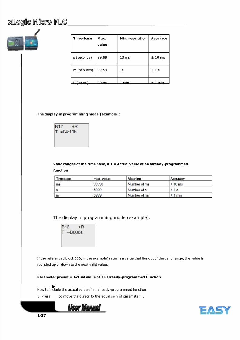
8/20/2019 XLogic User's Manual2
http://slidepdf.com/reader/full/xlogic-users-manual2 107/338
107
Time-base Max.
value
Min. resolution Accuracy
s (seconds) 99:99 10 ms ± 10 ms
m (minutes) 99:59 1s ± 1 s
h (hours) 99:59 1 min ± 1 min
The display in programming mode (example):
Valid ranges of the time base, if T = Actual value of an already-programmed
function
The display in programming mode (example):
If the referenced block (B6, in the example) returns a value that lies out of the valid range, the value is
rounded up or down to the next valid value.
Parameter preset = Actual value of an already-programmed function
How to include the actual value of an already-programmed function:
1. Press to move the cursor to the equal sign of parameter T.
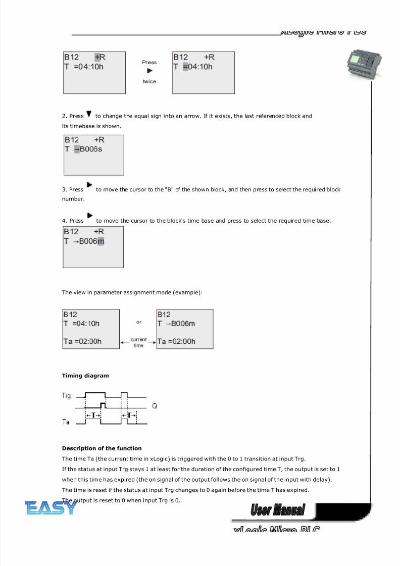
8/20/2019 XLogic User's Manual2
http://slidepdf.com/reader/full/xlogic-users-manual2 108/338
108
2. Press to change the equal sign into an arrow. If it exists, the last referenced block and
its timebase is shown.
3. Press to move the cursor to the "B" of the shown block, and then press to select the required block
number.
4. Press to move the cursor to the block's time base and press to select the required time base.
The view in parameter assignment mode (example):
Timing diagram
Description of the function
The time Ta (the current time in xLogic) is triggered with the 0 to 1 transition at input Trg.
If the status at input Trg stays 1 at least for the duration of the configured time T, the output is set to 1
when this time has expired (the on signal of the output follows the on signal of the input with delay).
The time is reset if the status at input Trg changes to 0 again before the time T has expired.
The output is reset to 0 when input Trg is 0.
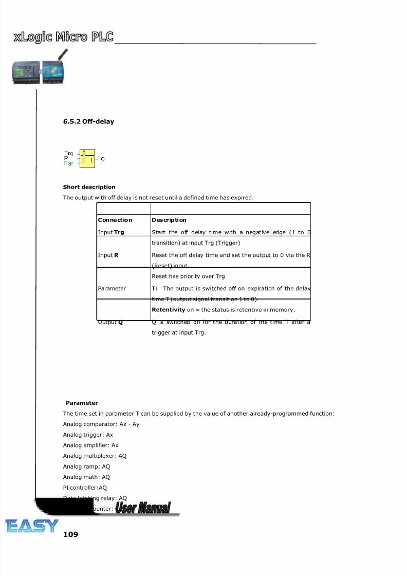
8/20/2019 XLogic User's Manual2
http://slidepdf.com/reader/full/xlogic-users-manual2 109/338
109
6.5.2 Off-delay
Short description
The output with off delay is not reset until a defined time has expired.
Connection Description
Input Trg Start the off delay time with a negative edge (1 to 0
transition) at input Trg (Trigger)
Input R Reset the off delay time and set the output to 0 via the R
(Reset) input.
Reset has priority over Trg
Parameter T: The output is switched off on expiration of the delay
time T (output signal transition 1 to 0).
Retentivity on = the status is retentive in memory.
Output Q Q is switched on for the duration of the time T after a
trigger at input Trg.
Parameter
The time set in parameter T can be supplied by the value of another already-programmed function:
Analog comparator: Ax - Ay
Analog trigger: Ax
Analog amplifier: Ax
Analog multiplexer: AQ
Analog ramp: AQ
Analog math: AQ
PI controller:AQ
Data latching relay: AQ
Up/Down counter: Cnt
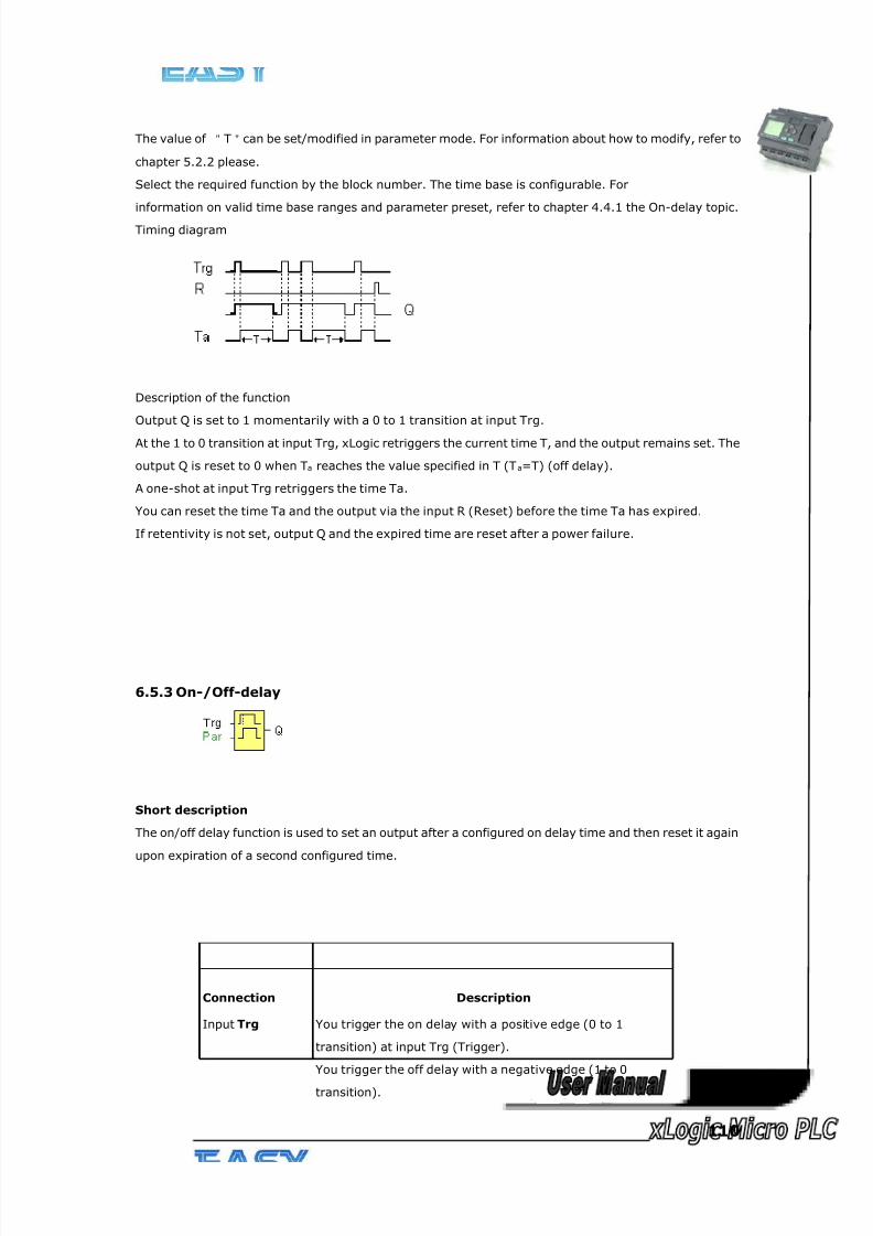
8/20/2019 XLogic User's Manual2
http://slidepdf.com/reader/full/xlogic-users-manual2 110/338
110
The value of "T"can be set/modified in parameter mode. For information about how to modify, refer to
chapter 5.2.2 please.
Select the required function by the block number. The time base is configurable. For
information on valid time base ranges and parameter preset, refer to chapter 4.4.1 the On-delay topic.
Timing diagram
Description of the function
Output Q is set to 1 momentarily with a 0 to 1 transition at input Trg.
At the 1 to 0 transition at input Trg, xLogic retriggers the current time T, and the output remains set. The
output Q is reset to 0 when Ta reaches the value specified in T (Ta=T) (off delay).
A one-shot at input Trg retriggers the time Ta.
You can reset the time Ta and the output via the input R (Reset) before the time Ta has expired.
If retentivity is not set, output Q and the expired time are reset after a power failure.
6.5.3 On-/Off-delay
Short description
The on/off delay function is used to set an output after a configured on delay time and then reset it again
upon expiration of a second configured time.
Connection Description
Input Trg You trigger the on delay with a positive edge (0 to 1
transition) at input Trg (Trigger).
You trigger the off delay with a negative edge (1 to 0
transition).
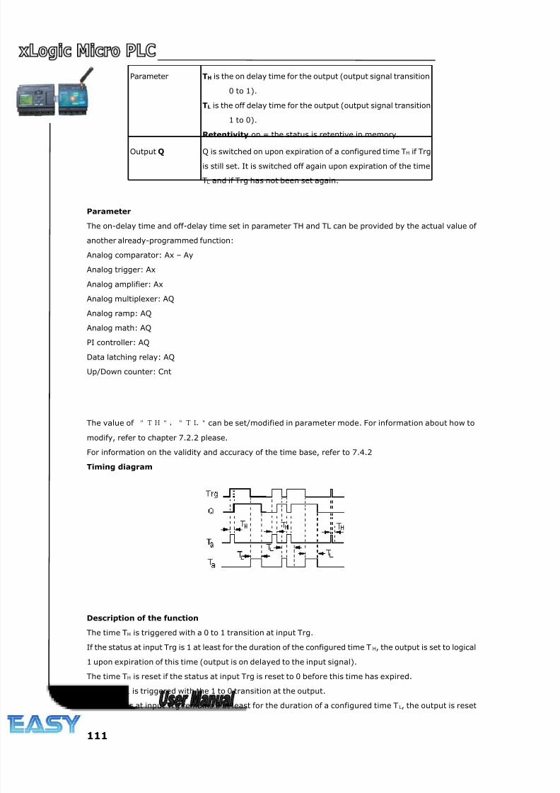
8/20/2019 XLogic User's Manual2
http://slidepdf.com/reader/full/xlogic-users-manual2 111/338
111
Parameter TH is the on delay time for the output (output signal transition
0 to 1).
TL is the off delay time for the output (output signal transition
1 to 0).
Retentivity on = the status is retentive in memory.
Output Q Q is switched on upon expiration of a configured time TH if Trg
is still set. It is switched off again upon expiration of the time
TL and if Trg has not been set again.
Parameter
The on-delay time and off-delay time set in parameter TH and TL can be provided by the actual value of
another already-programmed function:
Analog comparator: Ax – Ay
Analog trigger: Ax
Analog amplifier: Ax
Analog multiplexer: AQ
Analog ramp: AQ
Analog math: AQ
PI controller: AQ
Data latching relay: AQ
Up/Down counter: Cnt
The value of "TH","TL"can be set/modified in parameter mode. For information about how to
modify, refer to chapter 7.2.2 please.
For information on the validity and accuracy of the time base, refer to 7.4.2
Timing diagram
Description of the function
The time TH is triggered with a 0 to 1 transition at input Trg.
If the status at input Trg is 1 at least for the duration of the configured time T H, the output is set to logical
1 upon expiration of this time (output is on delayed to the input signal).
The time TH is reset if the status at input Trg is reset to 0 before this time has expired.
The time TL is triggered with the 1 to 0 transition at the output.If the status at input Trg remains 0 at least for the duration of a configured time T L, the output is reset
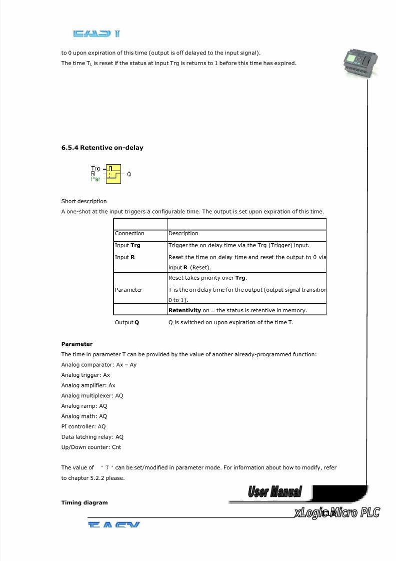
8/20/2019 XLogic User's Manual2
http://slidepdf.com/reader/full/xlogic-users-manual2 112/338
112
to 0 upon expiration of this time (output is off delayed to the input signal).
The time TL is reset if the status at input Trg is returns to 1 before this time has expired.
6.5.4 Retentive on-delay
Short description
A one-shot at the input triggers a configurable time. The output is set upon expiration of this time.
Connection Description
Input Trg Trigger the on delay time via the Trg (Trigger) input.
Input R Reset the time on delay time and reset the output to 0 via
input R (Reset).
Reset takes priority over Trg.
Parameter T is the on delay time for the output (output signal transition
0 to 1).
Retentivity on = the status is retentive in memory.
Output Q Q is switched on upon expiration of the time T.
Parameter
The time in parameter T can be provided by the value of another already-programmed function:
Analog comparator: Ax – Ay
Analog trigger: Ax
Analog amplifier: Ax
Analog multiplexer: AQ
Analog ramp: AQ
Analog math: AQ
PI controller: AQ
Data latching relay: AQ
Up/Down counter: Cnt
The value of "T"can be set/modified in parameter mode. For information about how to modify, refer
to chapter 5.2.2 please.
Timing diagram
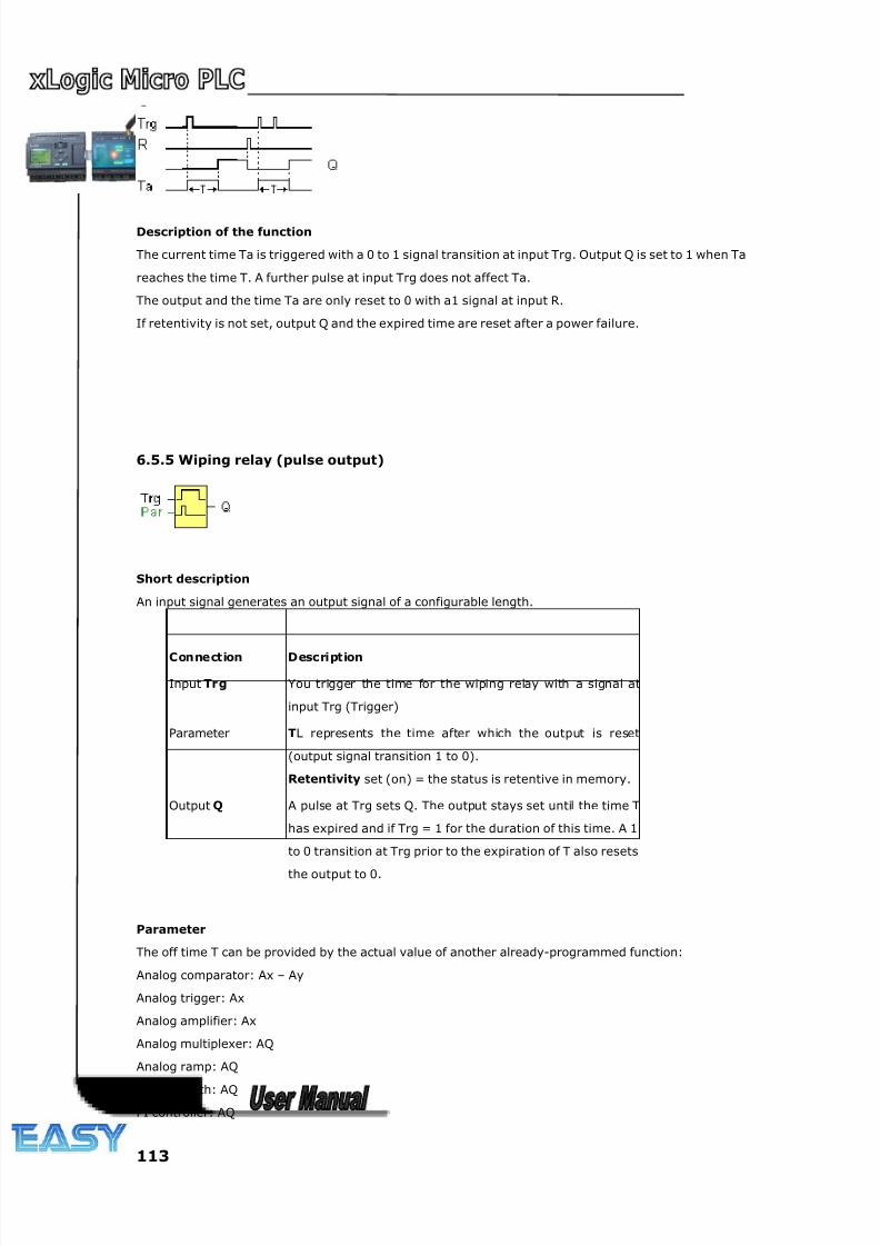
8/20/2019 XLogic User's Manual2
http://slidepdf.com/reader/full/xlogic-users-manual2 113/338
113
Description of the function
The current time Ta is triggered with a 0 to 1 signal transition at input Trg. Output Q is set to 1 when Ta
reaches the time T. A further pulse at input Trg does not affect Ta.
The output and the time Ta are only reset to 0 with a1 signal at input R.
If retentivity is not set, output Q and the expired time are reset after a power failure.
6.5.5 Wiping relay (pulse output)
Short description
An input signal generates an output signal of a configurable length.
Parameter
The off time T can be provided by the actual value of another already-programmed function:
Analog comparator: Ax – Ay
Analog trigger: Ax
Analog amplifier: Ax
Analog multiplexer: AQ
Analog ramp: AQ
Analog math: AQ
PI controller: AQ
Connection Description
Input Trg You trigger the time for the wiping relay with a signal at
input Trg (Trigger)
Parameter TL represents the time after which the output is reset
(output signal transition 1 to 0).
Retentivity set (on) = the status is retentive in memory.
Output Q A pulse at Trg sets Q. The output stays set until the time T
has expired and if Trg = 1 for the duration of this time. A 1
to 0 transition at Trg prior to the expiration of T also resets
the output to 0.
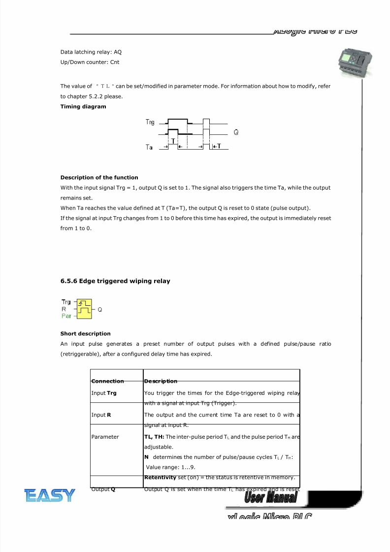
8/20/2019 XLogic User's Manual2
http://slidepdf.com/reader/full/xlogic-users-manual2 114/338
114
Data latching relay: AQ
Up/Down counter: Cnt
The value of "TL"can be set/modified in parameter mode. For information about how to modify, refer
to chapter 5.2.2 please.
Timing diagram
Description of the function
With the input signal Trg = 1, output Q is set to 1. The signal also triggers the time Ta, while the output
remains set.
When Ta reaches the value defined at T (Ta=T), the output Q is reset to 0 state (pulse output).
If the signal at input Trg changes from 1 to 0 before this time has expired, the output is immediately reset
from 1 to 0.
6.5.6 Edge triggered wiping relay
Short description
An input pulse generates a preset number of output pulses with a defined pulse/pause ratio
(retriggerable), after a configured delay time has expired.
Connection Description
Input Trg You trigger the times for the Edge-triggered wiping relay
with a signal at input Trg (Trigger).
Input R The output and the current time Ta are reset to 0 with a
signal at input R.
Parameter TL, TH: The inter-pulse period TL and the pulse period TH are
adjustable.
N determines the number of pulse/pause cycles TL / TH:
Value range: 1...9.
Retentivity set (on) = the status is retentive in memory.
Output Q Output Q is set when the time TL has expired and is reset
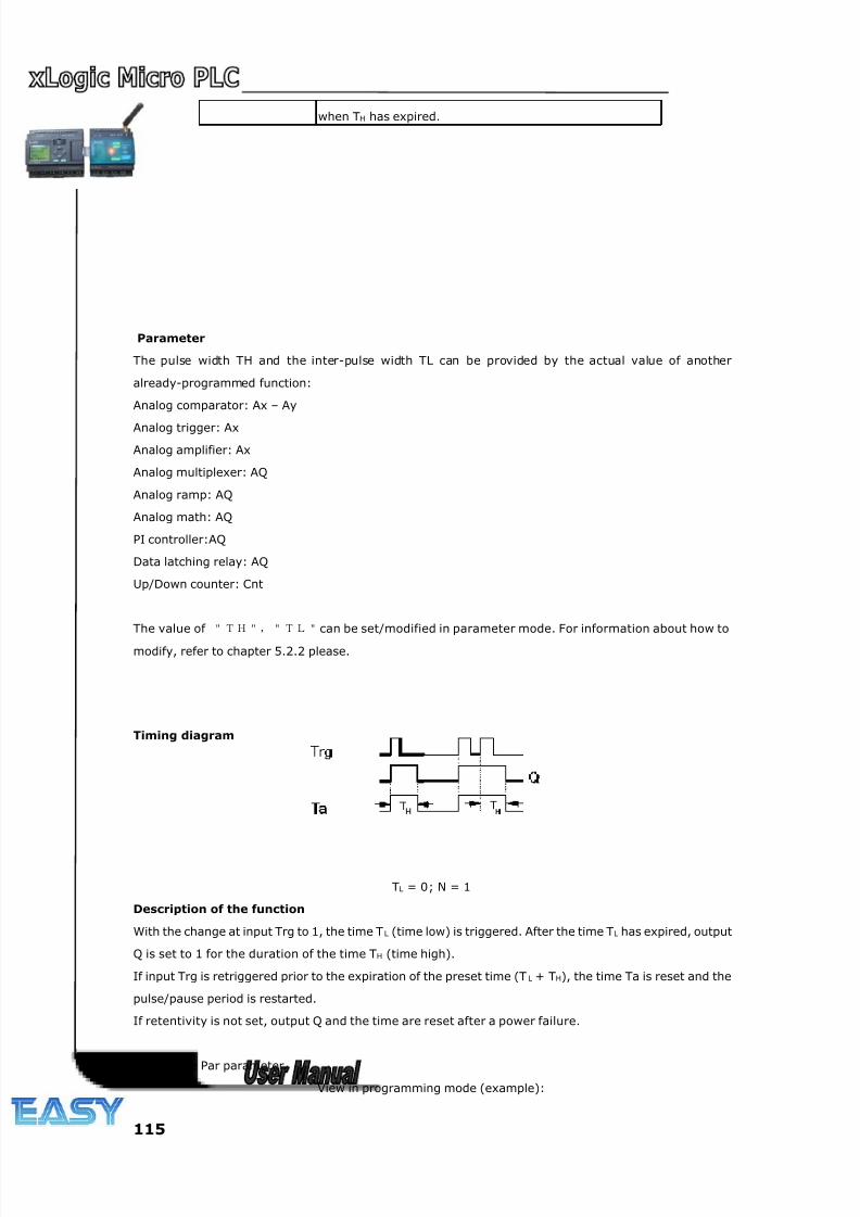
8/20/2019 XLogic User's Manual2
http://slidepdf.com/reader/full/xlogic-users-manual2 115/338
115
Parameter
The pulse width TH and the inter-pulse width TL can be provided by the actual value of another
already-programmed function:
Analog comparator: Ax – Ay
Analog trigger: Ax
Analog amplifier: Ax
Analog multiplexer: AQ
Analog ramp: AQ
Analog math: AQ
PI controller:AQ
Data latching relay: AQ
Up/Down counter: Cnt
The value of "TH","TL"can be set/modified in parameter mode. For information about how to
modify, refer to chapter 5.2.2 please.
Timing diagram
TL = 0; N = 1
Description of the function
With the change at input Trg to 1, the time T L (time low) is triggered. After the time TL has expired, output
Q is set to 1 for the duration of the time TH (time high).
If input Trg is retriggered prior to the expiration of the preset time (T L + TH), the time Ta is reset and the
pulse/pause period is restarted.
If retentivity is not set, output Q and the time are reset after a power failure.
Setting the Par parameter
View in programming mode (example):
when TH has expired.
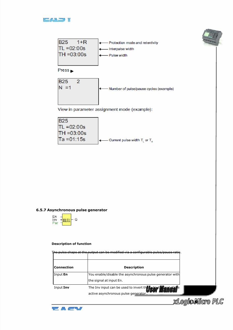
8/20/2019 XLogic User's Manual2
http://slidepdf.com/reader/full/xlogic-users-manual2 116/338
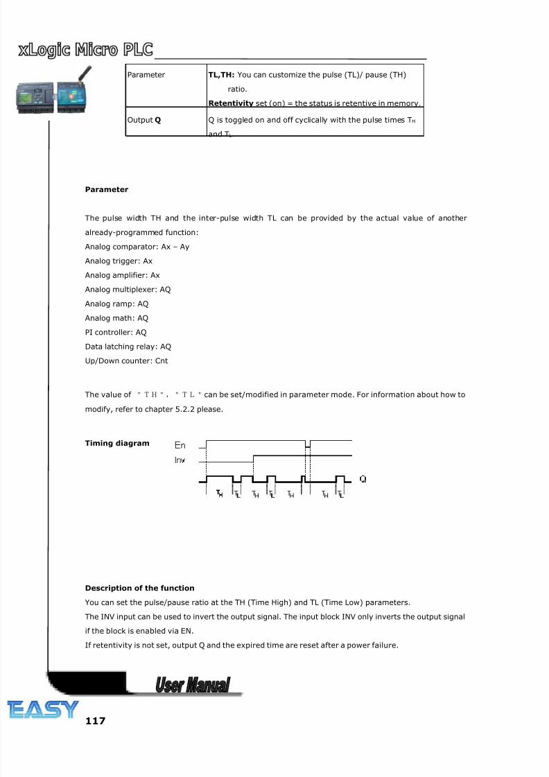
8/20/2019 XLogic User's Manual2
http://slidepdf.com/reader/full/xlogic-users-manual2 117/338
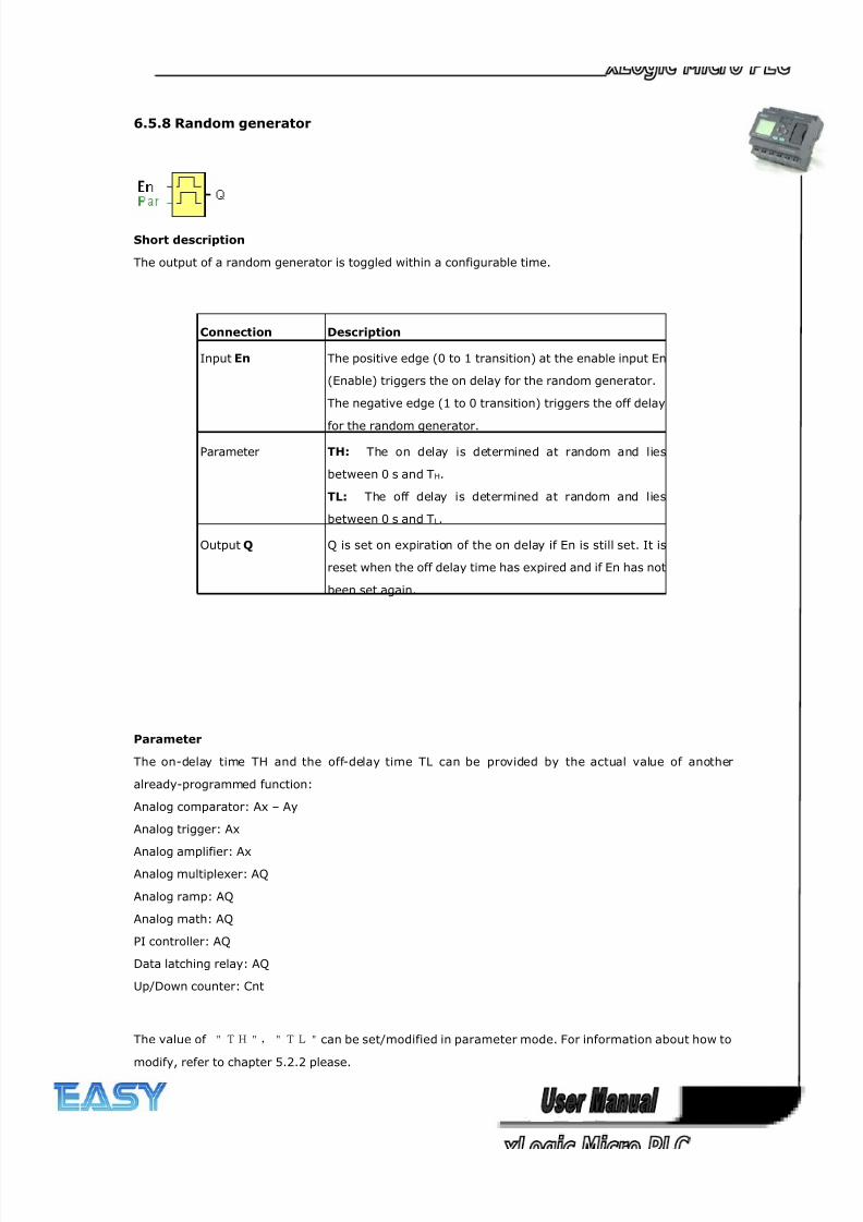
8/20/2019 XLogic User's Manual2
http://slidepdf.com/reader/full/xlogic-users-manual2 118/338
118
6.5.8 Random generator
Short description
The output of a random generator is toggled within a configurable time.
Connection Description
Input En The positive edge (0 to 1 transition) at the enable input En
(Enable) triggers the on delay for the random generator.
The negative edge (1 to 0 transition) triggers the off delay
for the random generator.
Parameter TH: The on delay is determined at random and lies
between 0 s and TH.
TL: The off delay is determined at random and lies
between 0 s and TL.
Output Q Q is set on expiration of the on delay if En is still set. It is
reset when the off delay time has expired and if En has not
been set again.
Parameter
The on-delay time TH and the off-delay time TL can be provided by the actual value of another
already-programmed function:
Analog comparator: Ax – Ay
Analog trigger: Ax
Analog amplifier: AxAnalog multiplexer: AQ
Analog ramp: AQ
Analog math: AQ
PI controller: AQ
Data latching relay: AQ
Up/Down counter: Cnt
The value of "TH","TL"can be set/modified in parameter mode. For information about how to
modify, refer to chapter 5.2.2 please.
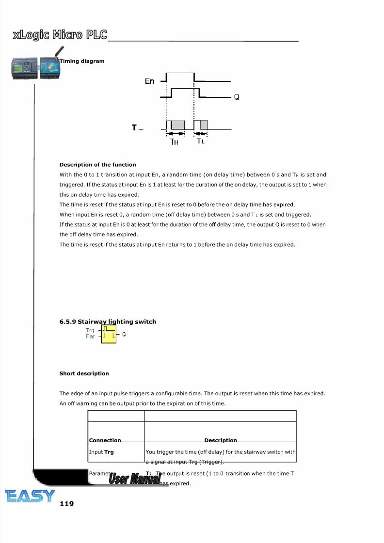
8/20/2019 XLogic User's Manual2
http://slidepdf.com/reader/full/xlogic-users-manual2 119/338
119
Timing diagram
Description of the function
With the 0 to 1 transition at input En, a random time (on delay time) between 0 s and TH is set and
triggered. If the status at input En is 1 at least for the duration of the on delay, the output is set to 1 when
this on delay time has expired.
The time is reset if the status at input En is reset to 0 before the on delay time has expired.
When input En is reset 0, a random time (off delay time) between 0 s and T L is set and triggered.
If the status at input En is 0 at least for the duration of the off delay time, the output Q is reset to 0 when
the off delay time has expired.
The time is reset if the status at input En returns to 1 before the on delay time has expired.
6.5.9 Stairway lighting switch
Short description
The edge of an input pulse triggers a configurable time. The output is reset when this time has expired.
An off warning can be output prior to the expiration of this time.
Connection Description
Input Trg You trigger the time (off delay) for the stairway switch with
a signal at input Trg (Trigger).
Parameter T: The output is reset (1 to 0 transition when the time Thas expired.
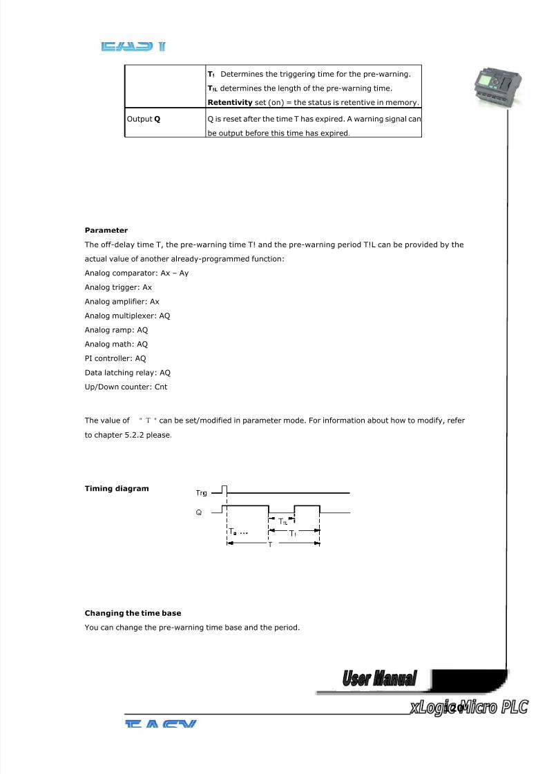
8/20/2019 XLogic User's Manual2
http://slidepdf.com/reader/full/xlogic-users-manual2 120/338
120
Parameter
The off-delay time T, the pre-warning time T! and the pre-warning period T!L can be provided by the
actual value of another already-programmed function:
Analog comparator: Ax – Ay
Analog trigger: Ax
Analog amplifier: Ax
Analog multiplexer: AQ
Analog ramp: AQ
Analog math: AQ
PI controller: AQ
Data latching relay: AQ
Up/Down counter: Cnt
The value of "T"can be set/modified in parameter mode. For information about how to modify, refer
to chapter 5.2.2 please.
Timing diagram
Changing the time base
You can change the pre-warning time base and the period.
T! Determines the triggering time for the pre-warning.
T!L determines the length of the pre-warning time.
Retentivity set (on) = the status is retentive in memory.
Output Q Q is reset after the time T has expired. A warning signal can
be output before this time has expired.
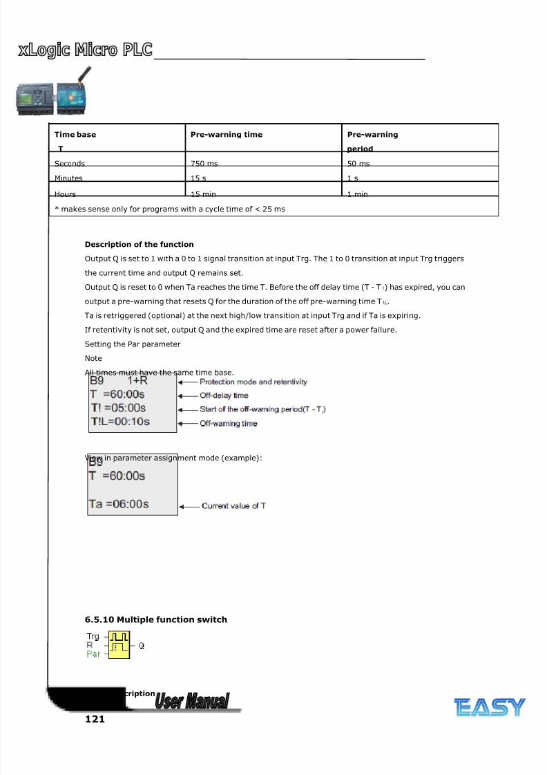
8/20/2019 XLogic User's Manual2
http://slidepdf.com/reader/full/xlogic-users-manual2 121/338
121
Description of the function
Output Q is set to 1 with a 0 to 1 signal transition at input Trg. The 1 to 0 transition at input Trg triggers
the current time and output Q remains set.
Output Q is reset to 0 when Ta reaches the time T. Before the off delay time (T - T !) has expired, you can
output a pre-warning that resets Q for the duration of the off pre-warning time T !L.
Ta is retriggered (optional) at the next high/low transition at input Trg and if Ta is expiring.
If retentivity is not set, output Q and the expired time are reset after a power failure.
Setting the Par parameter
Note
All times must have the same time base.
View in parameter assignment mode (example):
6.5.10 Multiple function switch
Short description
Time base
T
Pre-warning time Pre-warning
period
Seconds 750 ms 50 ms
Minutes 15 s 1 s
Hours 15 min 1 min
* makes sense only for programs with a cycle time of < 25 ms
8/20/2019 XLogic User's Manual2
http://slidepdf.com/reader/full/xlogic-users-manual2 122/338
122
Switch with two different functions:
Pulse switch with off delay
Switch (continuous light)
Connection Description
Input Trg With a signal at input Trg (Trigger) you set output Q
(continuous light), or reset Q with off delay. Output Q can
be reset with a signal at the Trg input.
Input R You set the current time Ta, and reset the output to 0, with
a signal at input R.
Parameter T: The output is reset (1 to 0 transition) when the time T
has expired.
TL determines the period during which the input must be
set in order to enable the permanent light function.
T! Determines the on delay for the pre-warning time.
T!L determines the length of the pre-warning time.
Retentivity set (on) = the status is retentive in memory.
Output Q Output Q is set with a signal at input Trg, and it is reset
again after a configured time has expired and depending
on the pulse width at input Trg, or it is reset with another
signal at input Trg.
Parameter
The off-delay time T, the permanent light time TL, the on-delay pre-warning time T!, and the pre-warning
time period T!L can be provided by the actual value of another already-programmed function:
Analog comparator: Ax – Ay
Analog trigger: Ax
Analog amplifier: Ax
Analog multiplexer: AQ
Analog ramp: AQ
Analog math: AQ
PI controller: AQ
Data latching relay: AQ
Up/Down counter: Cnt
The value of "T","TL"can be set/modified in parameter mode. For information about how to
modify, refer to chapter 5.2.2 please.
Timing diagram
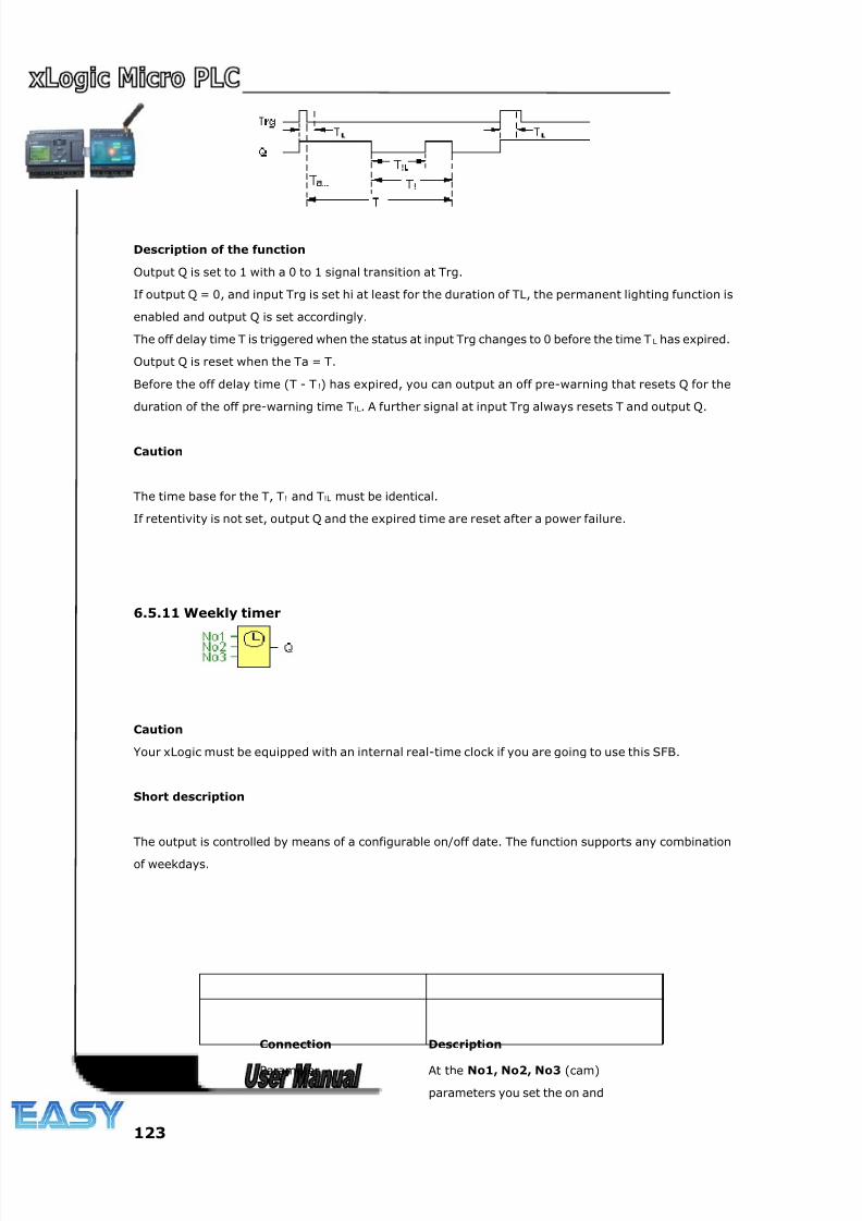
8/20/2019 XLogic User's Manual2
http://slidepdf.com/reader/full/xlogic-users-manual2 123/338
123
Description of the function
Output Q is set to 1 with a 0 to 1 signal transition at Trg.
If output Q = 0, and input Trg is set hi at least for the duration of TL, the permanent lighting function is
enabled and output Q is set accordingly.
The off delay time T is triggered when the status at input Trg changes to 0 before the time T L has expired.
Output Q is reset when the Ta = T.
Before the off delay time (T - T !) has expired, you can output an off pre-warning that resets Q for the
duration of the off pre-warning time T!L. A further signal at input Trg always resets T and output Q.
Caution
The time base for the T, T! and T!L must be identical.
If retentivity is not set, output Q and the expired time are reset after a power failure.
6.5.11 Weekly timer
Caution
Your xLogic must be equipped with an internal real-time clock if you are going to use this SFB.
Short description
The output is controlled by means of a configurable on/off date. The function supports any combination
of weekdays.
Connection Description
Parameter At the No1, No2, No3 (cam)
parameters you set the on and
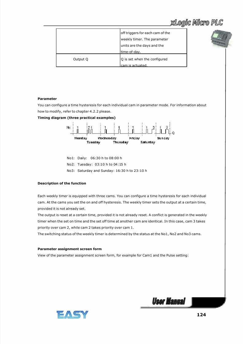
8/20/2019 XLogic User's Manual2
http://slidepdf.com/reader/full/xlogic-users-manual2 124/338
124
off triggers for each cam of the
weekly timer. The parameter
units are the days and the
time-of-day.
Output Q Q is set when the configuredcam is actuated.
Parameter
You can configure a time hysteresis for each individual cam in parameter mode. For information about
how to modify, refer to chapter 4.2.2 please.
Timing diagram (three practical examples)
No1: Daily: 06:30 h to 08:00 h
No2: Tuesday: 03:10 h to 04:15 h
No3: Saturday and Sunday: 16:30 h to 23:10 h
Description of the function
Each weekly timer is equipped with three cams. You can configure a time hysteresis for each individual
cam. At the cams you set the on and off hysteresis. The weekly timer sets the output at a certain time,
provided it is not already set.
The output is reset at a certain time, provided it is not already reset. A conflict is generated in the weekly
timer when the set on time and the set off time at another cam are identical. In this case, cam 3 takes
priority over cam 2, while cam 2 takes priority over cam 1.
The switching status of the weekly timer is determined by the status at the No1, No2 and No3 cams.
Parameter assignment screen form
View of the parameter assignment screen form, for example for Cam1 and the Pulse setting:
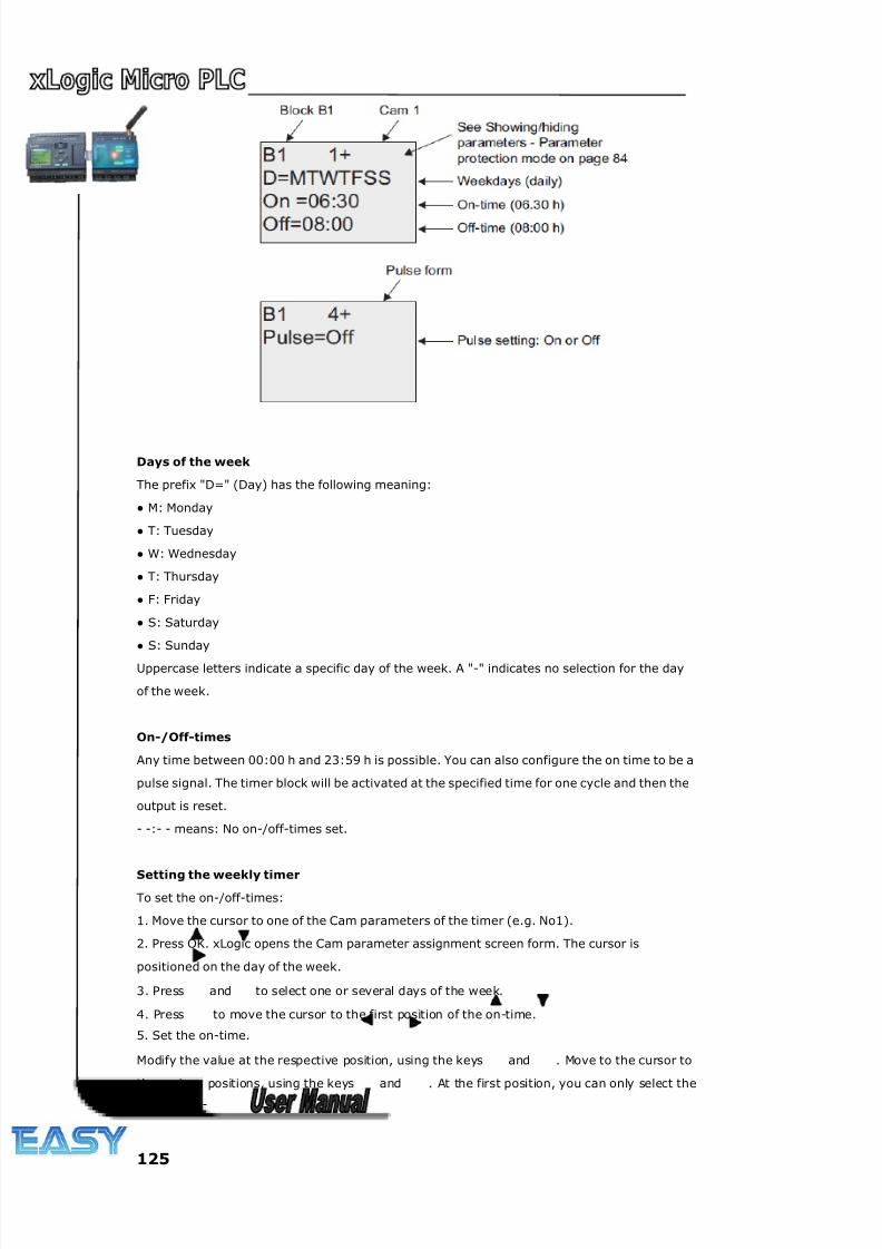
8/20/2019 XLogic User's Manual2
http://slidepdf.com/reader/full/xlogic-users-manual2 125/338
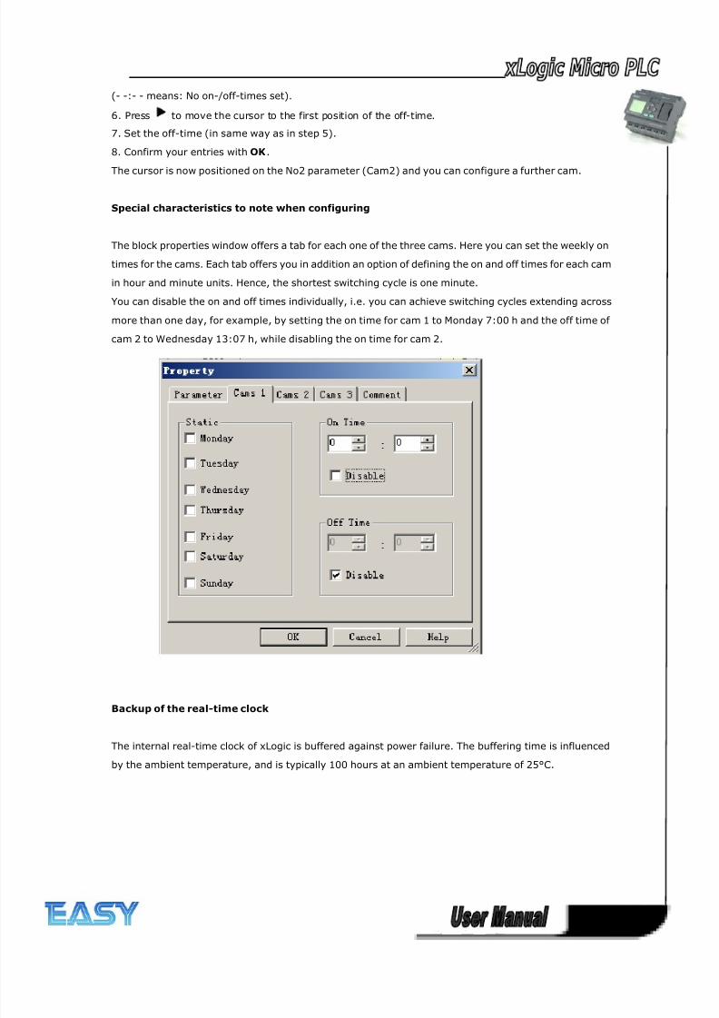
8/20/2019 XLogic User's Manual2
http://slidepdf.com/reader/full/xlogic-users-manual2 126/338
126
(- -:- - means: No on-/off-times set).
6. Press to move the cursor to the first position of the off-time.
7. Set the off-time (in same way as in step 5).
8. Confirm your entries with OK.
The cursor is now positioned on the No2 parameter (Cam2) and you can configure a further cam.
Special characteristics to note when configuring
The block properties window offers a tab for each one of the three cams. Here you can set the weekly on
times for the cams. Each tab offers you in addition an option of defining the on and off times for each cam
in hour and minute units. Hence, the shortest switching cycle is one minute.
You can disable the on and off times individually, i.e. you can achieve switching cycles extending across
more than one day, for example, by setting the on time for cam 1 to Monday 7:00 h and the off time of
cam 2 to Wednesday 13:07 h, while disabling the on time for cam 2.
Backup of the real-time clock
The internal real-time clock of xLogic is buffered against power failure. The buffering time is influenced
by the ambient temperature, and is typically 100 hours at an ambient temperature of 25°C.
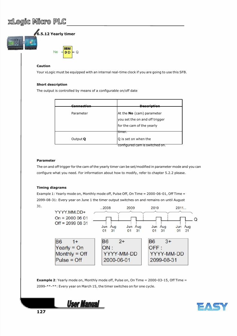
8/20/2019 XLogic User's Manual2
http://slidepdf.com/reader/full/xlogic-users-manual2 127/338
127
6.5.12 Yearly timer
Caution
Your xLogic must be equipped with an internal real-time clock if you are going to use this SFB.
Short description
The output is controlled by means of a configurable on/off date
Connection Description
Parameter At the No (cam) parameter
you set the on and off trigger
for the cam of the yearly
timer.
Output Q Q is set on when the
configured cam is switched on.
Parameter
The on and off trigger for the cam of the yearly timer can be set/modified in parameter mode and you can
configure what you need. For information about how to modify, refer to chapter 5.2.2 please.
Timing diagrams
Example 1: Yearly mode on, Monthly mode off, Pulse Off, On Time = 2000-06-01, Off Time =
2099-08-31: Every year on June 1 the timer output switches on and remains on until August
31.
Example 2: Yearly mode on, Monthly mode off, Pulse on, On Time = 2000-03-15, Off Time =
2099-**-**: Every year on March 15, the timer switches on for one cycle.
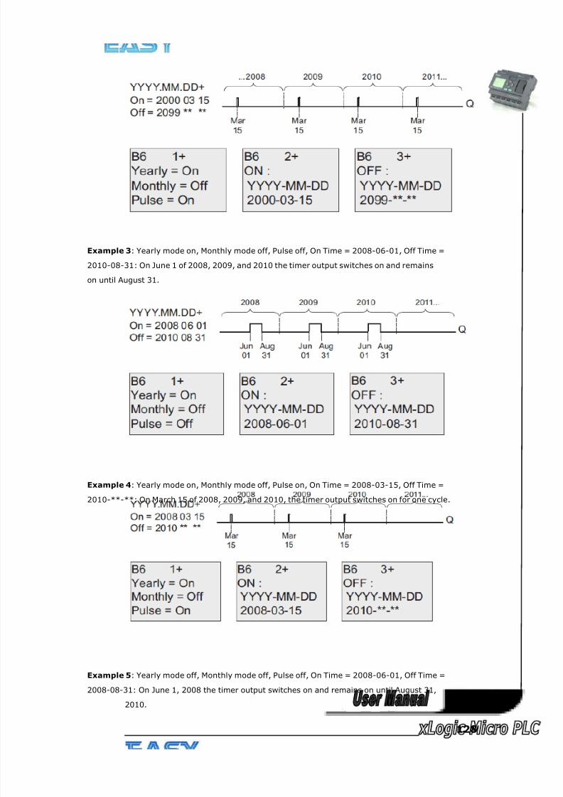
8/20/2019 XLogic User's Manual2
http://slidepdf.com/reader/full/xlogic-users-manual2 128/338
128
Example 3: Yearly mode on, Monthly mode off, Pulse off, On Time = 2008-06-01, Off Time =
2010-08-31: On June 1 of 2008, 2009, and 2010 the timer output switches on and remains
on until August 31.
Example 4: Yearly mode on, Monthly mode off, Pulse on, On Time = 2008-03-15, Off Time =
2010-**-**: On March 15 of 2008, 2009, and 2010, the timer output switches on for one cycle.
Example 5: Yearly mode off, Monthly mode off, Pulse off, On Time = 2008-06-01, Off Time =
2008-08-31: On June 1, 2008 the timer output switches on and remains on until August 31,
2010.
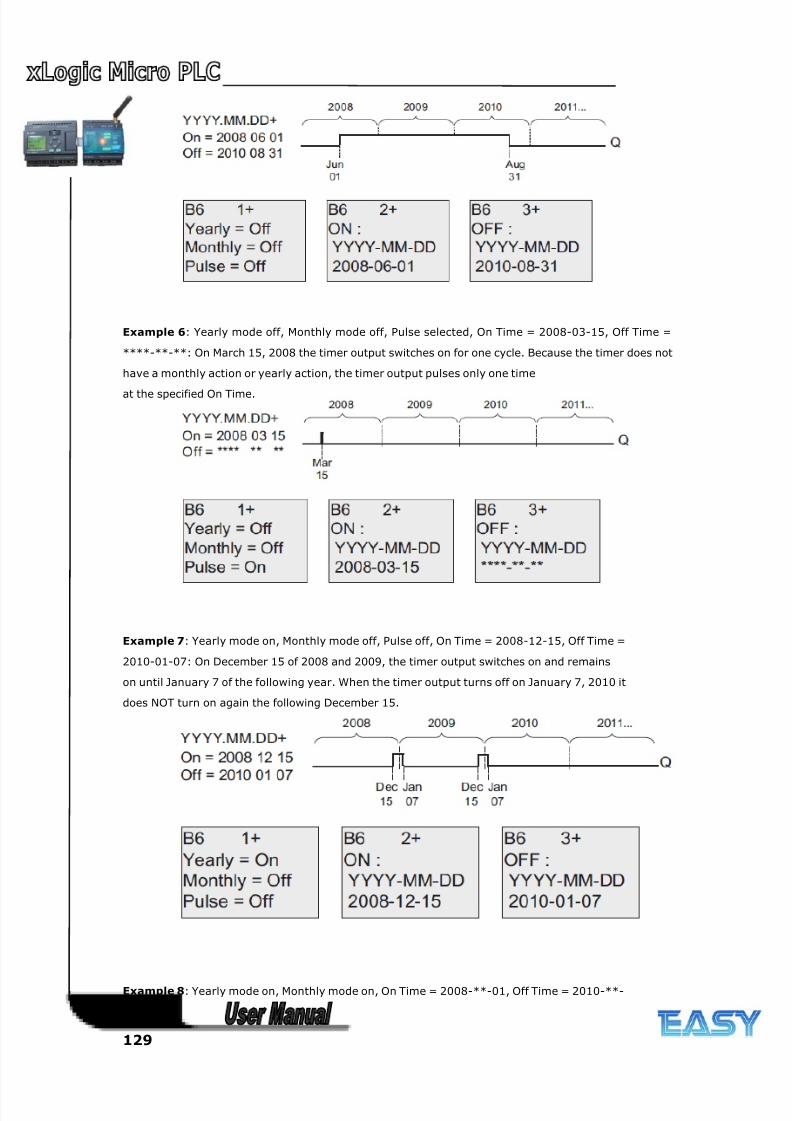
8/20/2019 XLogic User's Manual2
http://slidepdf.com/reader/full/xlogic-users-manual2 129/338
129
Example 6: Yearly mode off, Monthly mode off, Pulse selected, On Time = 2008-03-15, Off Time =
****-**-**: On March 15, 2008 the timer output switches on for one cycle. Because the timer does not
have a monthly action or yearly action, the timer output pulses only one time
at the specified On Time.
Example 7: Yearly mode on, Monthly mode off, Pulse off, On Time = 2008-12-15, Off Time =
2010-01-07: On December 15 of 2008 and 2009, the timer output switches on and remains
on until January 7 of the following year. When the timer output turns off on January 7, 2010 it
does NOT turn on again the following December 15.
Example 8: Yearly mode on, Monthly mode on, On Time = 2008-**-01, Off Time = 2010-**-
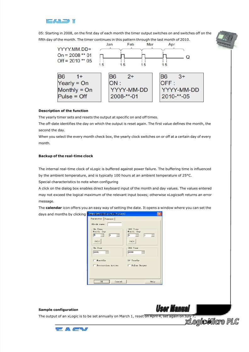
8/20/2019 XLogic User's Manual2
http://slidepdf.com/reader/full/xlogic-users-manual2 130/338
130
05: Starting in 2008, on the first day of each month the timer output switches on and switches off on the
fifth day of the month. The timer continues in this pattern through the last month of 2010.
Description of the function
The yearly timer sets and resets the output at specific on and off times.
The off-date identifies the day on which the output is reset again. The first value defines the month, the
second the day.
When you select the every month check box, the yearly clock switches on or off at a certain day of every
month.
Backup of the real-time clock
The internal real-time clock of xLogic is buffered against power failure. The buffering time is influenced
by the ambient temperature, and is typically 100 hours at an ambient temperature of 25°C.
Special characteristics to note when configuring
A click on the dialog box enables direct keyboard input of the month and day values. The values entered
may not exceed the logical maximum of the relevant input boxes; otherwise xLogicsoft returns an error
message.
The calendar icon offers you an easy way of setting the date. It opens a window where you can set the
days and months by clicking the relevant buttons.
Sample configuration
The output of an xLogic is to be set annually on March 1, reset on April 4, set again on July 7,
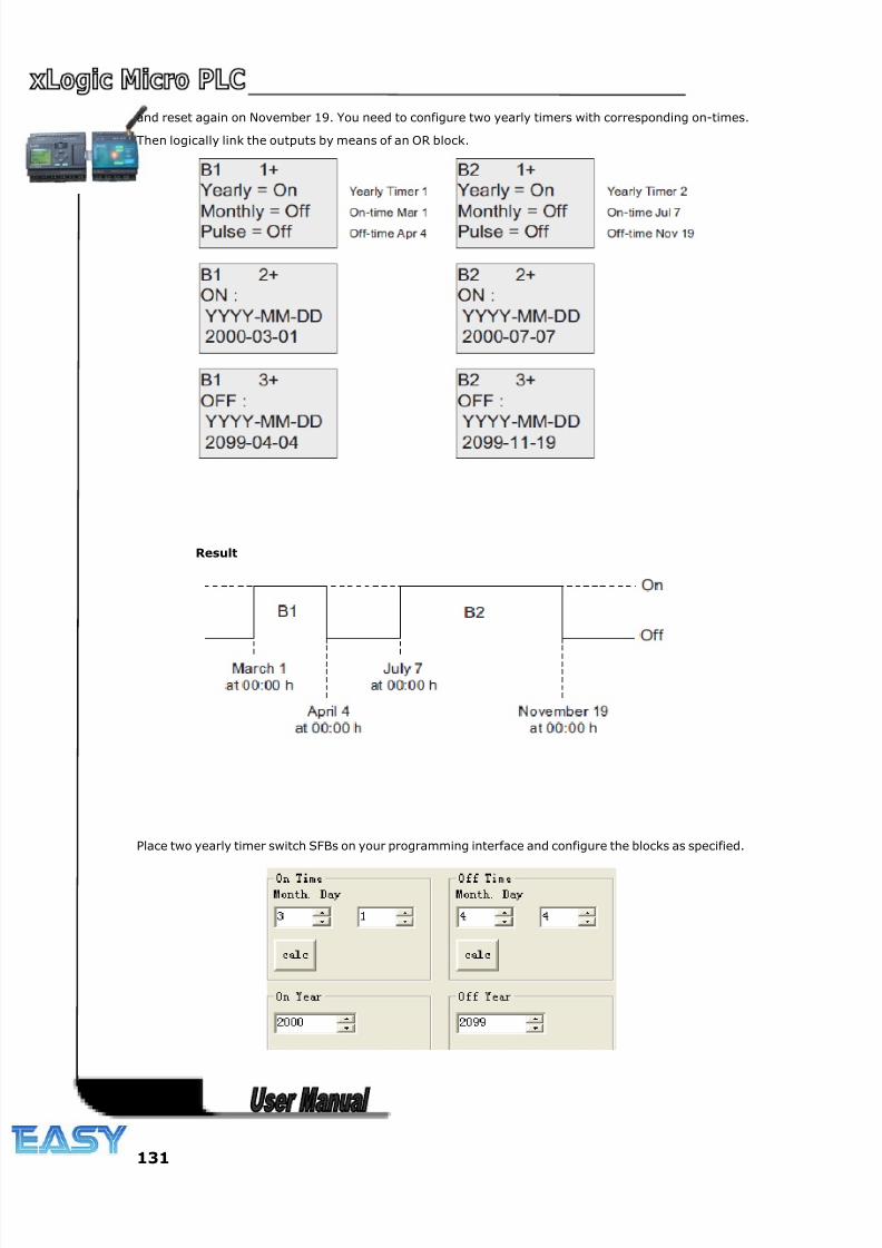
8/20/2019 XLogic User's Manual2
http://slidepdf.com/reader/full/xlogic-users-manual2 131/338
131
and reset again on November 19. You need to configure two yearly timers with corresponding on-times.
Then logically link the outputs by means of an OR block.
Result
Place two yearly timer switch SFBs on your programming interface and configure the blocks as specified.
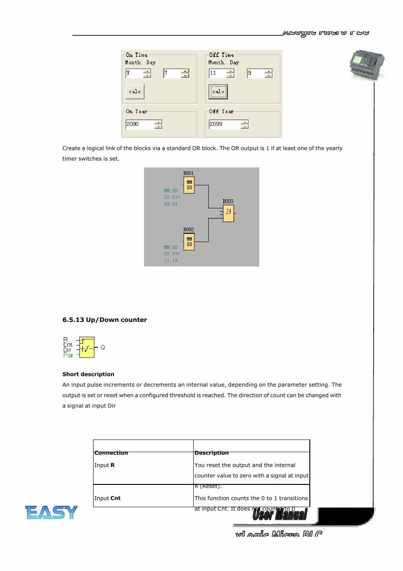
8/20/2019 XLogic User's Manual2
http://slidepdf.com/reader/full/xlogic-users-manual2 132/338
132
Create a logical link of the blocks via a standard OR block. The OR output is 1 if at least one of the yearly
timer switches is set.
6.5.13 Up/Down counter
Short description
An input pulse increments or decrements an internal value, depending on the parameter setting. The
output is set or reset when a configured threshold is reached. The direction of count can be changed with
a signal at input Dir
Connection Description
Input R You reset the output and the internal
counter value to zero with a signal at input
R (Reset).
Input Cnt This function counts the 0 to 1 transitionsat input Cnt. It does not count 1 to 0
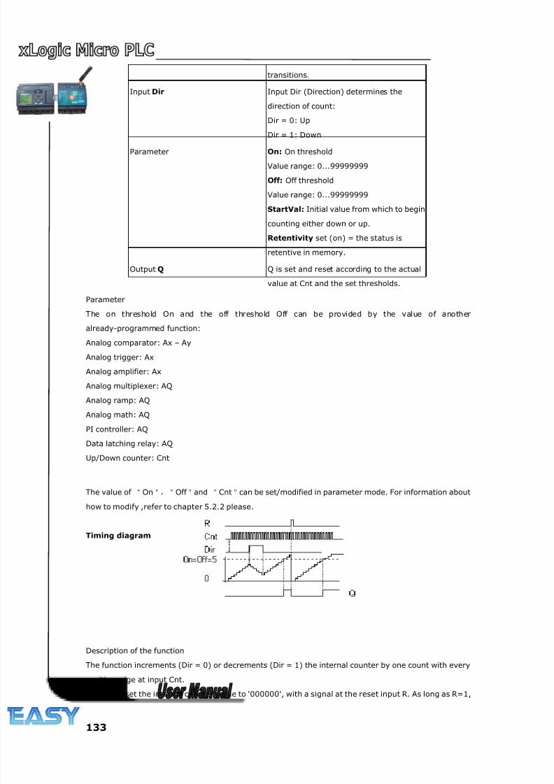
8/20/2019 XLogic User's Manual2
http://slidepdf.com/reader/full/xlogic-users-manual2 133/338
133
transitions.
Input Dir Input Dir (Direction) determines the
direction of count:
Dir = 0: Up
Dir = 1: Down
Parameter On: On threshold
Value range: 0...99999999
Off: Off threshold
Value range: 0...99999999
StartVal: Initial value from which to begin
counting either down or up.
Retentivity set (on) = the status is
retentive in memory.
Output Q Q is set and reset according to the actual
value at Cnt and the set thresholds.
Parameter
The on threshold On and the off threshold Off can be provided by the value of another
already-programmed function:
Analog comparator: Ax – Ay
Analog trigger: Ax
Analog amplifier: Ax
Analog multiplexer: AQ
Analog ramp: AQ
Analog math: AQ
PI controller: AQ
Data latching relay: AQ
Up/Down counter: Cnt
The value of "On","Off "and "Cnt"can be set/modified in parameter mode. For information about
how to modify ,refer to chapter 5.2.2 please.
Timing diagram
Description of the function
The function increments (Dir = 0) or decrements (Dir = 1) the internal counter by one count with every
positive edge at input Cnt.
You can reset the internal counter value to '000000', with a signal at the reset input R. As long as R=1,
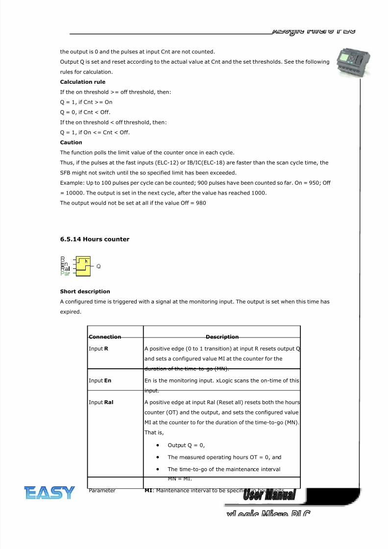
8/20/2019 XLogic User's Manual2
http://slidepdf.com/reader/full/xlogic-users-manual2 134/338
134
the output is 0 and the pulses at input Cnt are not counted.
Output Q is set and reset according to the actual value at Cnt and the set thresholds. See the following
rules for calculation.
Calculation rule
If the on threshold >= off threshold, then:
Q = 1, if Cnt >= On
Q = 0, if Cnt < Off.
If the on threshold < off threshold, then:
Q = 1, if On <= Cnt < Off.
Caution
The function polls the limit value of the counter once in each cycle.
Thus, if the pulses at the fast inputs (ELC-12) or IB/IC(ELC-18) are faster than the scan cycle time, the
SFB might not switch until the so specified limit has been exceeded.
Example: Up to 100 pulses per cycle can be counted; 900 pulses have been counted so far. On = 950; Off
= 10000. The output is set in the next cycle, after the value has reached 1000.
The output would not be set at all if the value Off = 980
6.5.14 Hours counter
Short description
A configured time is triggered with a signal at the monitoring input. The output is set when this time has
expired.
Connection Description
Input R A positive edge (0 to 1 transition) at input R resets output Q
and sets a configured value MI at the counter for the
duration of the time-to-go (MN).
Input En En is the monitoring input. xLogic scans the on-time of this
input.
Input Ral A positive edge at input Ral (Reset all) resets both the hours
counter (OT) and the output, and sets the configured value
MI at the counter to for the duration of the time-to-go (MN).
That is,
• Output Q = 0,
• The measured operating hours OT = 0, and
• The time-to-go of the maintenance interval
MN = MI.
Parameter MI: Maintenance interval to be specified in hour units
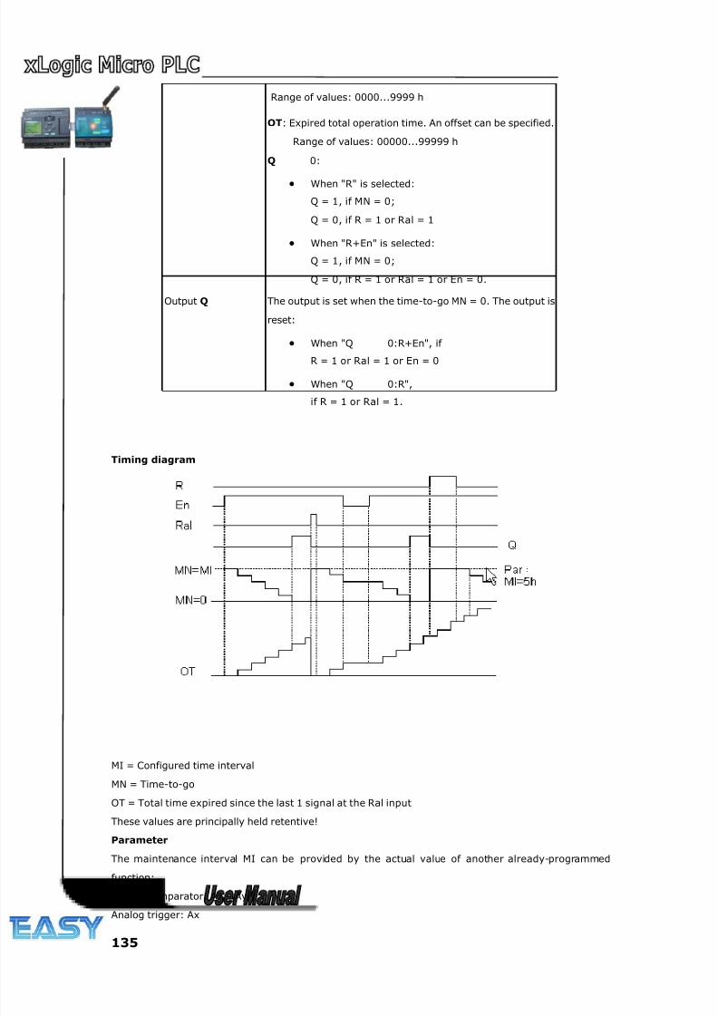
8/20/2019 XLogic User's Manual2
http://slidepdf.com/reader/full/xlogic-users-manual2 135/338
135
Range of values: 0000...9999 h
OT: Expired total operation time. An offset can be specified.
Range of values: 00000...99999 h
Q 0:
• When "R" is selected:
Q = 1, if MN = 0;
Q = 0, if R = 1 or Ral = 1
• When "R+En" is selected:
Q = 1, if MN = 0;
Q = 0, if R = 1 or Ral = 1 or En = 0.
Output Q The output is set when the time-to-go MN = 0. The output is
reset:
• When "Q 0:R+En", if
R = 1 or Ral = 1 or En = 0
• When "Q 0:R",
if R = 1 or Ral = 1.
Timing diagram
MI = Configured time interval
MN = Time-to-go
OT = Total time expired since the last 1 signal at the Ral input
These values are principally held retentive!
Parameter
The maintenance interval MI can be provided by the actual value of another already-programmed
function:
Analog comparator: Ax – Ay
Analog trigger: Ax
8/20/2019 XLogic User's Manual2
http://slidepdf.com/reader/full/xlogic-users-manual2 136/338
136
Analog amplifier: Ax
Analog multiplexer: AQ
Analog ramp: AQ
Analog math: AQ
PI controller: AQ
Data latching relay: AQ
Up/Down counter: Cnt
The value of "MI" can be set and modified in parameter mode. For information about how to modify,
refer to chapter 4.2.2 please.
Description of the function
The hours counter monitors input En. As long as the status at this input is 1, xLogic calculates the time
expired and the time-to-go MN. xLogic displays these times when set to configuration mode. The output
is set to 1 when the time-to-go is equal to zero.
You reset output Q and the time-to-go counter to the specified value MI with a signal at input R. The
operation hour counter OT remains unaffected.
You reset output Q and the time-to-go counter to the specified value MI with a signal at input Ral. The
operation hour counter OT is reset to 0.
Depending on your configuration of the Q parameter, the output is either reset with a reset signal at input
R or Ral, or when the reset signal is 1 or the En signal is 0.
Limit value of OT
The values of the operating hours in OT are retained when you reset the hours counter with a signal at
input R. The hours counter OT continues the count as long as En = 1, irrespective of the status at the
reset input R. The counter limit of OT is 99999 h. The hours counter stops when it reaches this value.
In programming mode, you can set the initial value of OT. The counter starts operation at any value other
than zero. MN is automatically calculated at the START, based on the MI and OT values.
Example: MI = 100, OT = 130, the result is MN = 70
Parameter preset
In xLogicsoft, you can define MI and an OT start value.
You determine that Q does not depend on En by selecting the corresponding check box.
Retentivity with the hours counter
The hours counter in the xLogic is generally retentive.
However, if the values of the hours counter are lost after a power failure, then select the respective block
in your circuit program. Right mouse click on the hours counter and select Block Properties > Parameters.
The option Retentivity must be activated and not changeable (grayed out).
If the Retentivity option is not available, then delete the block and insert a new special function hours
counter at the same position.
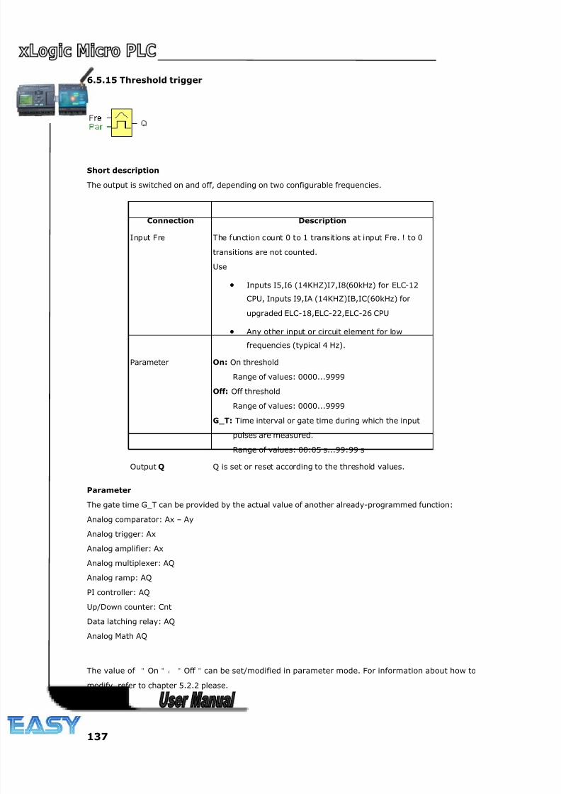
8/20/2019 XLogic User's Manual2
http://slidepdf.com/reader/full/xlogic-users-manual2 137/338
137
6.5.15 Threshold trigger
Short description
The output is switched on and off, depending on two configurable frequencies.
Parameter
The gate time G_T can be provided by the actual value of another already-programmed function:
Analog comparator: Ax – Ay
Analog trigger: Ax
Analog amplifier: Ax
Analog multiplexer: AQ
Analog ramp: AQ
PI controller: AQ
Up/Down counter: Cnt
Data latching relay: AQ
Analog Math AQ
The value of "On","Off "can be set/modified in parameter mode. For information about how to
modify, refer to chapter 5.2.2 please.
Connection Description
Input Fre The function count 0 to 1 transitions at input Fre. ! to 0
transitions are not counted.
Use
• Inputs I5,I6 (14KHZ)I7,I8(60kHz) for ELC-12
CPU, Inputs I9,IA (14KHZ)IB,IC(60kHz) for
upgraded ELC-18,ELC-22,ELC-26 CPU
• Any other input or circuit element for low
frequencies (typical 4 Hz).
Parameter On: On threshold
Range of values: 0000...9999
Off: Off threshold
Range of values: 0000...9999
G_T: Time interval or gate time during which the input
pulses are measured.
Range of values: 00:05 s...99:99 s
Output Q Q is set or reset according to the threshold values.
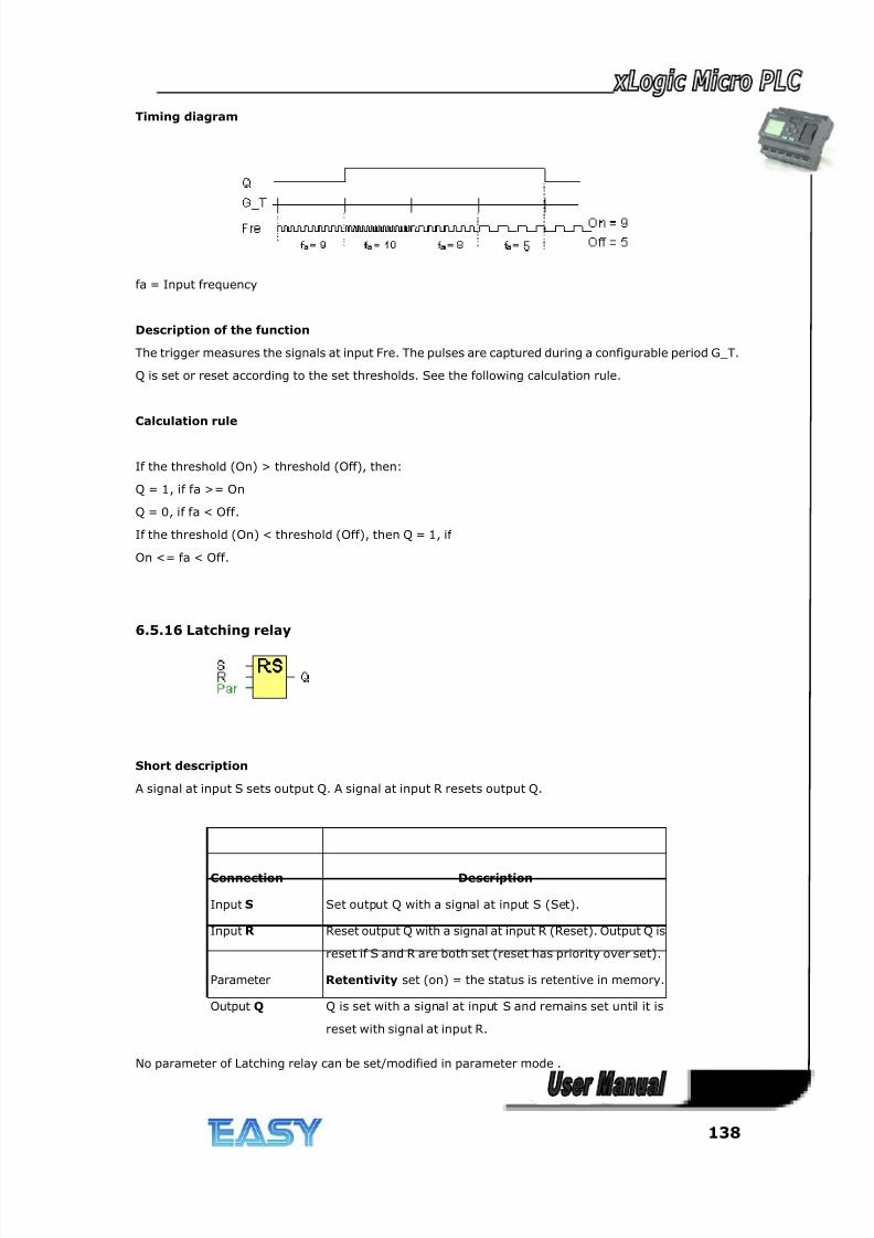
8/20/2019 XLogic User's Manual2
http://slidepdf.com/reader/full/xlogic-users-manual2 138/338
138
Timing diagram
fa = Input frequency
Description of the function
The trigger measures the signals at input Fre. The pulses are captured during a configurable period G_T.
Q is set or reset according to the set thresholds. See the following calculation rule.
Calculation rule
If the threshold (On) > threshold (Off), then:
Q = 1, if fa >= On
Q = 0, if fa < Off.
If the threshold (On) < threshold (Off), then Q = 1, if
On <= fa < Off.
6.5.16 Latching relay
Short description
A signal at input S sets output Q. A signal at input R resets output Q.
No parameter of Latching relay can be set/modified in parameter mode .
Connection Description
Input S Set output Q with a signal at input S (Set).
Input R Reset output Q with a signal at input R (Reset). Output Q is
reset if S and R are both set (reset has priority over set).
Parameter Retentivity set (on) = the status is retentive in memory.
Output Q Q is set with a signal at input S and remains set until it is
reset with signal at input R.
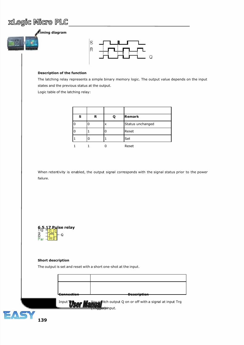
8/20/2019 XLogic User's Manual2
http://slidepdf.com/reader/full/xlogic-users-manual2 139/338
139
Timing diagram
Description of the function
The latching relay represents a simple binary memory logic. The output value depends on the input
states and the previous status at the output.
Logic table of the latching relay:
S R Q Remark
0 0 x Status unchanged
0 1 0 Reset
1 0 1 Set
1 1 0 Reset
When retentivity is enabled, the output signal corresponds with the signal status prior to the power
failure.
6.5.17 Pulse relay
Short description
The output is set and reset with a short one-shot at the input.
Connection Description
Input Trg You switch output Q on or off with a signal at input Trg
(Trigger) input.
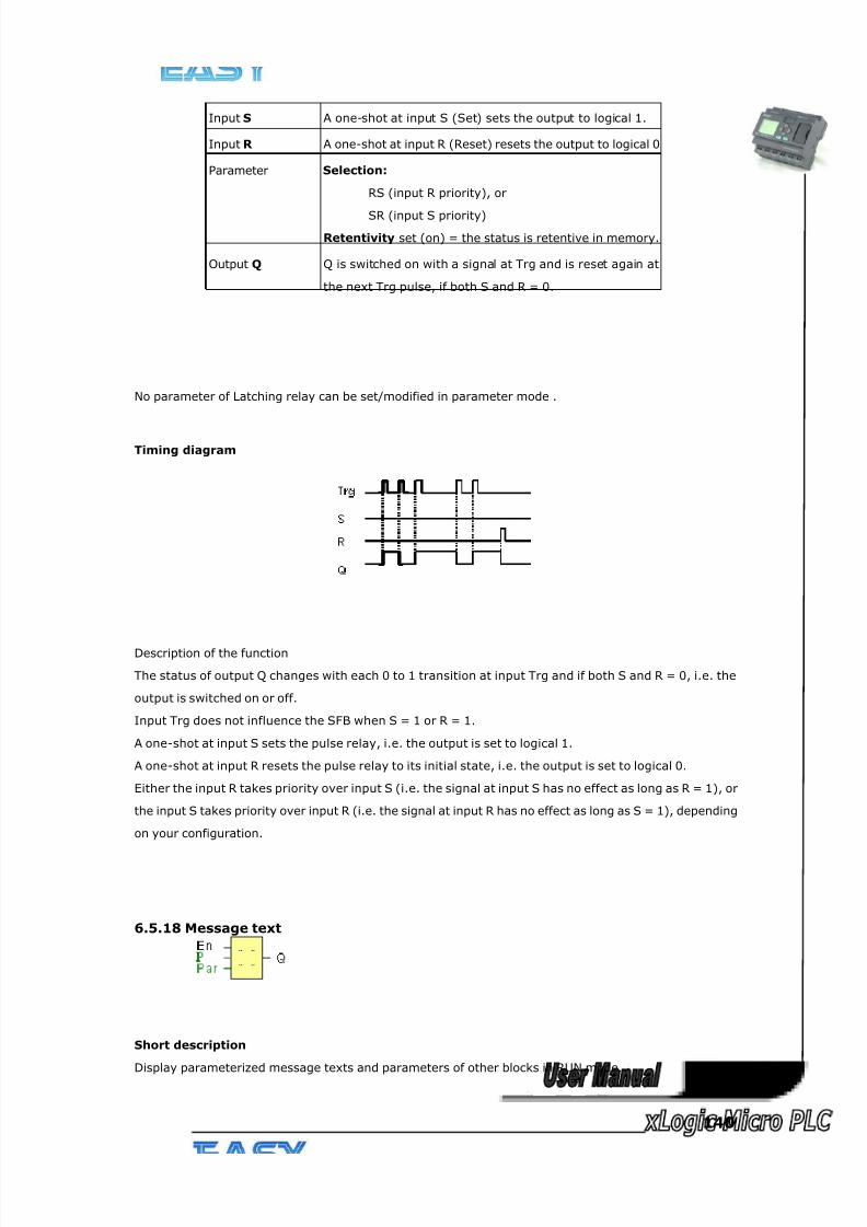
8/20/2019 XLogic User's Manual2
http://slidepdf.com/reader/full/xlogic-users-manual2 140/338
140
No parameter of Latching relay can be set/modified in parameter mode .
Timing diagram
Description of the function
The status of output Q changes with each 0 to 1 transition at input Trg and if both S and R = 0, i.e. the
output is switched on or off.
Input Trg does not influence the SFB when S = 1 or R = 1.
A one-shot at input S sets the pulse relay, i.e. the output is set to logical 1.
A one-shot at input R resets the pulse relay to its initial state, i.e. the output is set to logical 0.
Either the input R takes priority over input S (i.e. the signal at input S has no effect as long as R = 1), or
the input S takes priority over input R (i.e. the signal at input R has no effect as long as S = 1), depending
on your configuration.
6.5.18 Message text
Short description
Display parameterized message texts and parameters of other blocks in RUN mode.
Input S A one-shot at input S (Set) sets the output to logical 1.
Input R A one-shot at input R (Reset) resets the output to logical 0
Parameter Selection:
RS (input R priority), or
SR (input S priority)
Retentivity set (on) = the status is retentive in memory.
Output Q Q is switched on with a signal at Trg and is reset again at
the next Trg pulse, if both S and R = 0.
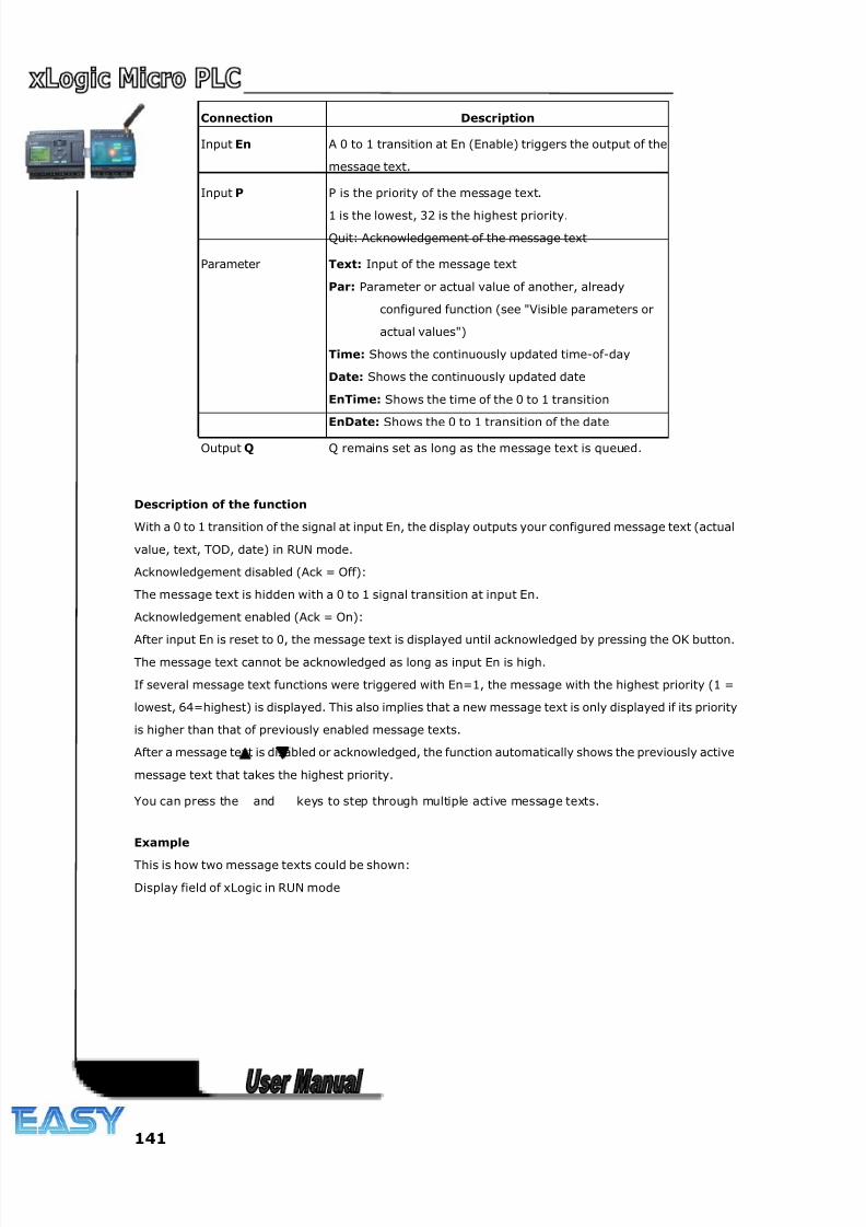
8/20/2019 XLogic User's Manual2
http://slidepdf.com/reader/full/xlogic-users-manual2 141/338
141
Connection Description
Input En A 0 to 1 transition at En (Enable) triggers the output of the
message text.
Input P P is the priority of the message text.
1 is the lowest, 32 is the highest priority.
Quit: Acknowledgement of the message text
Parameter Text: Input of the message text
Par: Parameter or actual value of another, already
configured function (see "Visible parameters or
actual values")
Time: Shows the continuously updated time-of-day
Date: Shows the continuously updated date
EnTime: Shows the time of the 0 to 1 transition
EnDate: Shows the 0 to 1 transition of the date
Output Q Q remains set as long as the message text is queued.
Description of the function
With a 0 to 1 transition of the signal at input En, the display outputs your configured message text (actual
value, text, TOD, date) in RUN mode.
Acknowledgement disabled (Ack = Off):
The message text is hidden with a 0 to 1 signal transition at input En.
Acknowledgement enabled (Ack = On):
After input En is reset to 0, the message text is displayed until acknowledged by pressing the OK button.The message text cannot be acknowledged as long as input En is high.
If several message text functions were triggered with En=1, the message with the highest priority (1 =
lowest, 64=highest) is displayed. This also implies that a new message text is only displayed if its priority
is higher than that of previously enabled message texts.
After a message text is disabled or acknowledged, the function automatically shows the previously active
message text that takes the highest priority.
You can press the and keys to step through multiple active message texts.
Example
This is how two message texts could be shown:
Display field of xLogic in RUN mode
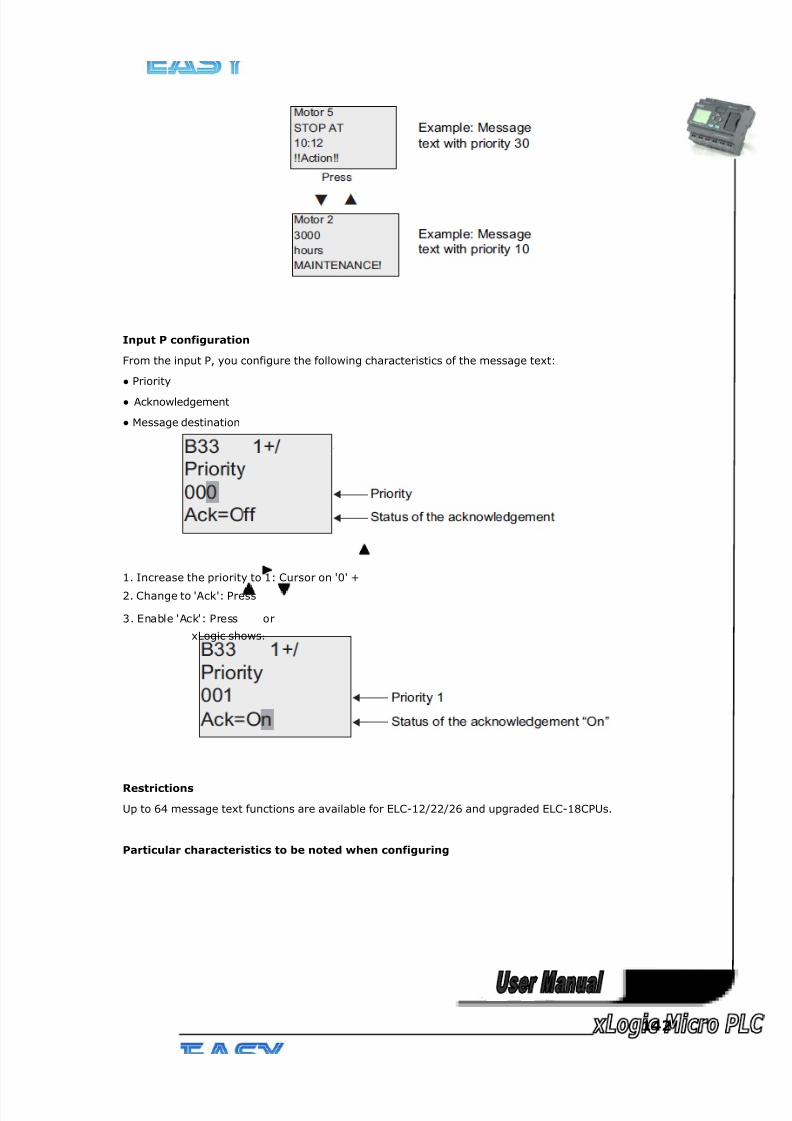
8/20/2019 XLogic User's Manual2
http://slidepdf.com/reader/full/xlogic-users-manual2 142/338
142
Input P configuration
From the input P, you configure the following characteristics of the message text:
● Priority
● Acknowledgement
● Message destination
1. Increase the priority to 1: Cursor on '0' +
2. Change to 'Ack': Press
3. Enable 'Ack': Press or
xLogic shows:
Restrictions
Up to 64 message text functions are available for ELC-12/22/26 and upgraded ELC-18CPUs.
Particular characteristics to be noted when configuring
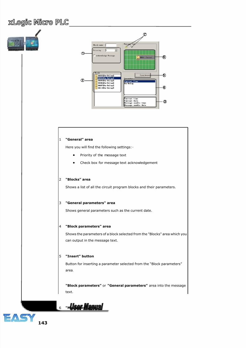
8/20/2019 XLogic User's Manual2
http://slidepdf.com/reader/full/xlogic-users-manual2 143/338
143
1 "General" area
Here you will find the following settings:·
• Priority of the message text
• Check box for message text acknowledgement
2 "Blocks" area
Shows a list of all the circuit program blocks and their parameters.
3 "General parameters" area
Shows general parameters such as the current date.
4 "Block parameters" area
Shows the parameters of a block selected from the "Blocks" area which you
can output in the message text.
5 "Insert" button
Button for inserting a parameter selected from the “Block parameters”
area.
"Block parameters" or "General parameters" area into the message
text.
6 "Messages" area
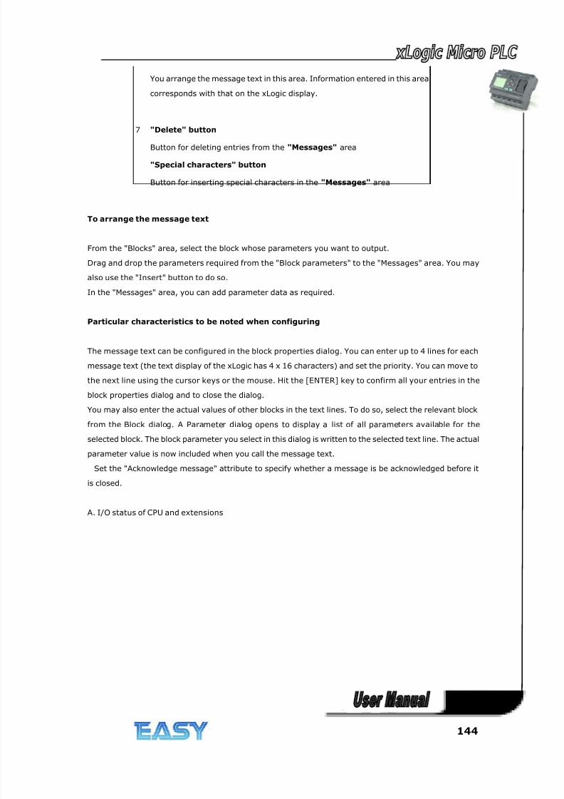
8/20/2019 XLogic User's Manual2
http://slidepdf.com/reader/full/xlogic-users-manual2 144/338
144
You arrange the message text in this area. Information entered in this area
corresponds with that on the xLogic display.
7 "Delete" button
Button for deleting entries from the "Messages" area
"Special characters" button
Button for inserting special characters in the "Messages" area
To arrange the message text
From the "Blocks" area, select the block whose parameters you want to output.
Drag and drop the parameters required from the "Block parameters" to the "Messages" area. You may
also use the "Insert" button to do so.
In the "Messages" area, you can add parameter data as required.
Particular characteristics to be noted when configuring
The message text can be configured in the block properties dialog. You can enter up to 4 lines for each
message text (the text display of the xLogic has 4 x 16 characters) and set the priority. You can move to
the next line using the cursor keys or the mouse. Hit the [ENTER] key to confirm all your entries in the
block properties dialog and to close the dialog.
You may also enter the actual values of other blocks in the text lines. To do so, select the relevant block
from the Block dialog. A Parameter dialog opens to display a list of all parameters available for the
selected block. The block parameter you select in this dialog is written to the selected text line. The actual
parameter value is now included when you call the message text.
Set the "Acknowledge message" attribute to specify whether a message is be acknowledged before it
is closed.
A. I/O status of CPU and extensions
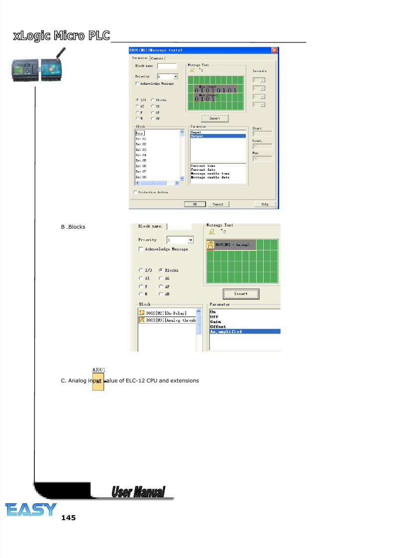
8/20/2019 XLogic User's Manual2
http://slidepdf.com/reader/full/xlogic-users-manual2 145/338
145
B .Blocks
C. Analog input value of ELC-12 CPU and extensions
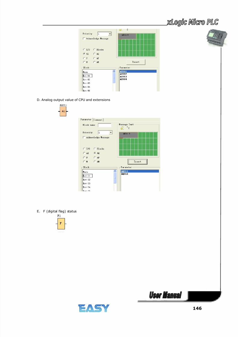
8/20/2019 XLogic User's Manual2
http://slidepdf.com/reader/full/xlogic-users-manual2 146/338
146
D. Analog output value of CPU and extensions
E. F (digital flag) status
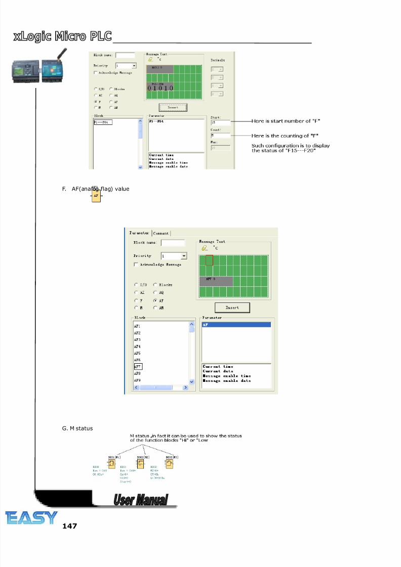
8/20/2019 XLogic User's Manual2
http://slidepdf.com/reader/full/xlogic-users-manual2 147/338
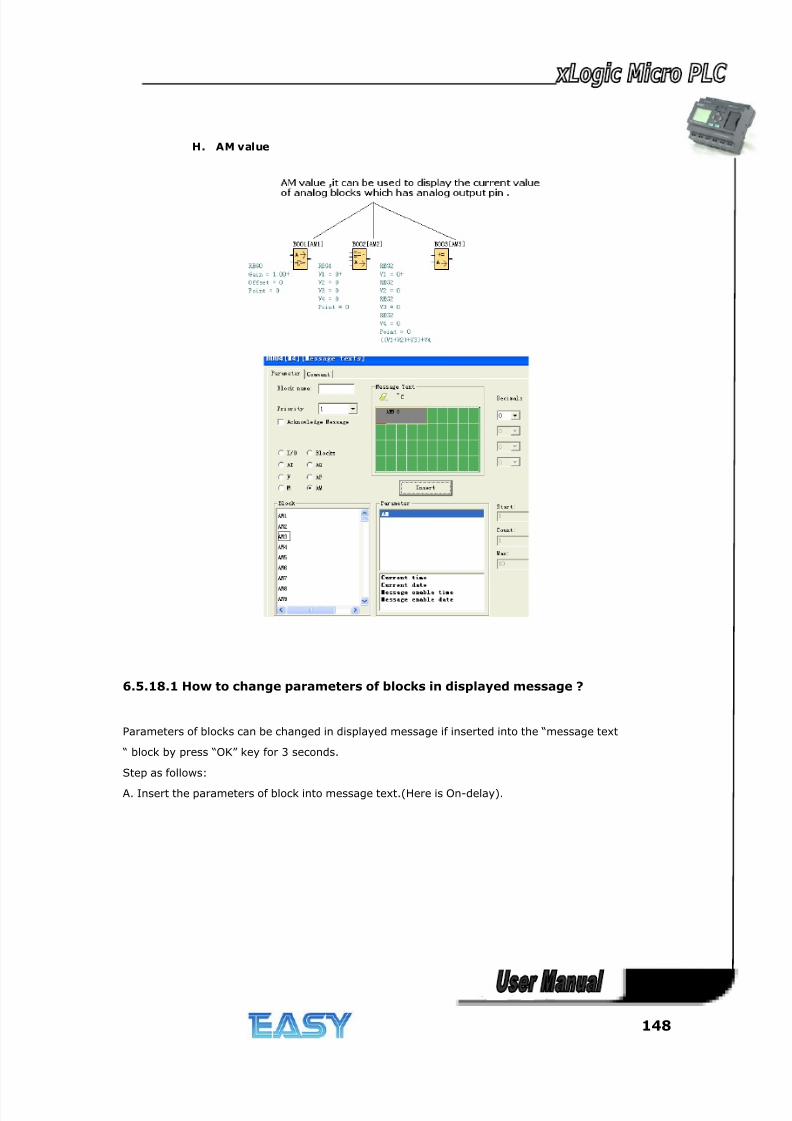
8/20/2019 XLogic User's Manual2
http://slidepdf.com/reader/full/xlogic-users-manual2 148/338
148
H. AM value
6.5.18.1 How to change parameters of blocks in displayed message ?
Parameters of blocks can be changed in displayed message if inserted into the “message text
“ block by press “OK” key for 3 seconds.
Step as follows:
A. Insert the parameters of block into message text.(Here is On-delay).
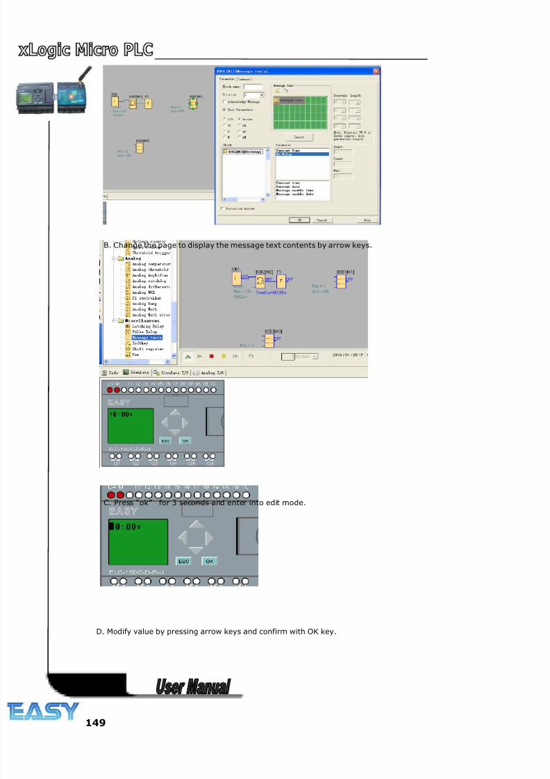
8/20/2019 XLogic User's Manual2
http://slidepdf.com/reader/full/xlogic-users-manual2 149/338
149
B. Change the page to display the message text contents by arrow keys.
C. Press “ok” for 3 seconds and enter into edit mode.
D. Modify value by pressing arrow keys and confirm with OK key.
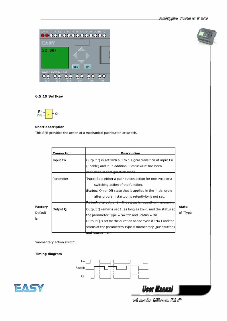
8/20/2019 XLogic User's Manual2
http://slidepdf.com/reader/full/xlogic-users-manual2 150/338
150
6.5.19 Softkey
Short description
This SFB provides the action of a mechanical pushbutton or switch.
Factory state
Default of 'Type'
is
'momentary action switch'.
Timing diagram
Connection Description
Input En Output Q is set with a 0 to 1 signal transition at input En
(Enable) and if, in addition, 'Status=On' has been
confirmed in configuration mode.
Parameter Type: Sets either a pushbutton action for one cycle or a
switching action of the function.
Status: On or Off state that is applied in the initial cycle
after program startup, is retentivity is not set.
Retentivity set (on) = the status is retentive in memory.
Output Q Output Q remains set 1, as long as En=1 and the status at
the parameter Type = Switch and Status = On.
Output Q is set for the duration of one cycle if EN=1 and the
status at the parameters Type = momentary (pushbutton)
and Status = On.
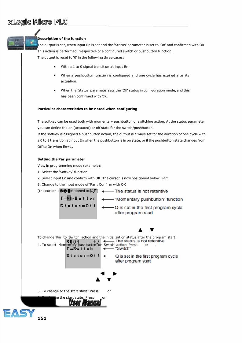
8/20/2019 XLogic User's Manual2
http://slidepdf.com/reader/full/xlogic-users-manual2 151/338
151
Description of the function
The output is set, when input En is set and the 'Status' parameter is set to 'On' and confirmed with OK.
This action is performed irrespective of a configured switch or pushbutton function.
The output is reset to '0' in the following three cases:
• With a 1 to 0 signal transition at input En.
• When a pushbutton function is configured and one cycle has expired after its
actuation.
• When the 'Status' parameter sets the 'Off' status in configuration mode, and this
has been confirmed with OK.
Particular characteristics to be noted when configuring
The softkey can be used both with momentary pushbutton or switching action. At the status parameter
you can define the on (actuated) or off state for the switch/pushbutton.
If the softkey is assigned a pushbutton action, the output is always set for the duration of one cycle with
a 0 to 1 transition at input En when the pushbutton is in on state, or if the pushbutton state changes from
Off to On when En=1.
Setting the Par parameter
View in programming mode (example):
1. Select the 'Softkey' function.
2. Select input En and confirm with OK. The cursor is now positioned below 'Par'.
3. Change to the input mode of 'Par': Confirm with OK
(the cursor is now positioned to 'Off')
To change 'Par' to 'Switch' action and the initialization status after the program start:
4. To select 'Momentary pushbutton' or 'Switch' action: Press or .
5. To change to the start state: Press or
6. To change the start state: Press or
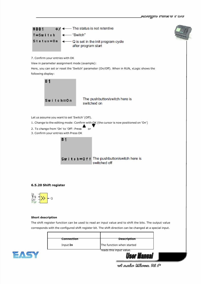
8/20/2019 XLogic User's Manual2
http://slidepdf.com/reader/full/xlogic-users-manual2 152/338
152
7. Confirm your entries with OK
View in parameter assignment mode (example):
Here, you can set or reset the 'Switch' parameter (On/Off). When in RUN, xLogic shows the
following display:
Let us assume you want to set 'Switch' (Off).
1. Change to the editing mode: Confirm with OK (the cursor is now positioned on 'On')
2. To change from 'On' to 'Off': Press or
3. Confirm your entries with Press OK
6.5.20 Shift register
Short description
The shift register function can be used to read an input value and to shift the bits. The output value
corresponds with the configured shift register bit. The shift direction can be changed at a special input.
Connection Description
Input In The function when started
reads this input value.
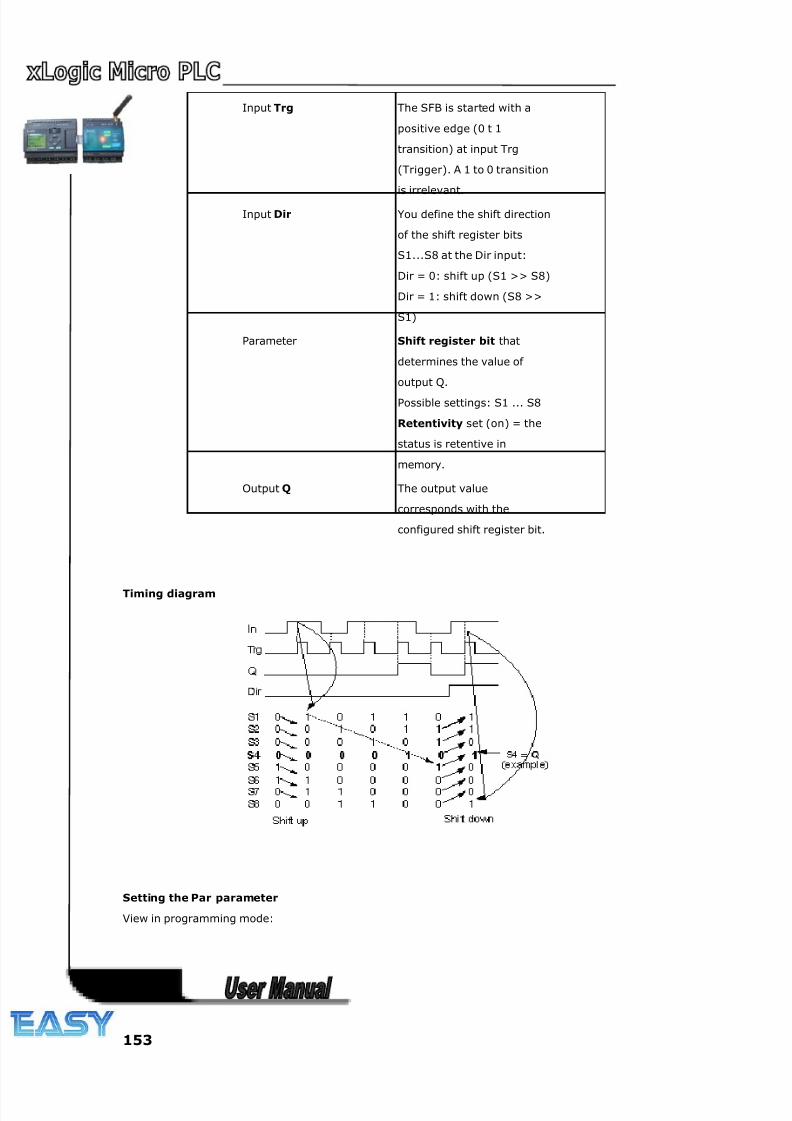
8/20/2019 XLogic User's Manual2
http://slidepdf.com/reader/full/xlogic-users-manual2 153/338
153
Input Trg The SFB is started with a
positive edge (0 t 1
transition) at input Trg
(Trigger). A 1 to 0 transition
is irrelevant.
Input Dir You define the shift direction
of the shift register bits
S1...S8 at the Dir input:
Dir = 0: shift up (S1 >> S8)
Dir = 1: shift down (S8 >>
S1)
Parameter Shift register bit that
determines the value of
output Q.
Possible settings: S1 ... S8
Retentivity set (on) = the
status is retentive in
memory.
Output Q The output value
corresponds with the
configured shift register bit.
Timing diagram
Setting the Par parameter
View in programming mode:
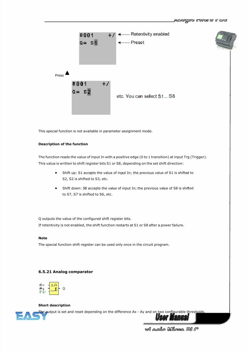
8/20/2019 XLogic User's Manual2
http://slidepdf.com/reader/full/xlogic-users-manual2 154/338
154
Press
This special function is not available in parameter assignment mode.
Description of the function
The function reads the value of input In with a positive edge (0 to 1 transition) at input Trg (Trigger).
This value is written to shift register bits S1 or S8, depending on the set shift direction:
• Shift up: S1 accepts the value of input In; the previous value of S1 is shifted to
S2, S2 is shifted to S3, etc.
• Shift down: S8 accepts the value of input In; the previous value of S8 is shifted
to S7, S7 is shifted to S6, etc.
Q outputs the value of the configured shift register bits.
If retentivity is not enabled, the shift function restarts at S1 or S8 after a power failure.
Note
The special function shift register can be used only once in the circuit program.
6.5.21 Analog comparator
Short description
The output is set and reset depending on the difference Ax - Ay and on two configurable thresholds.
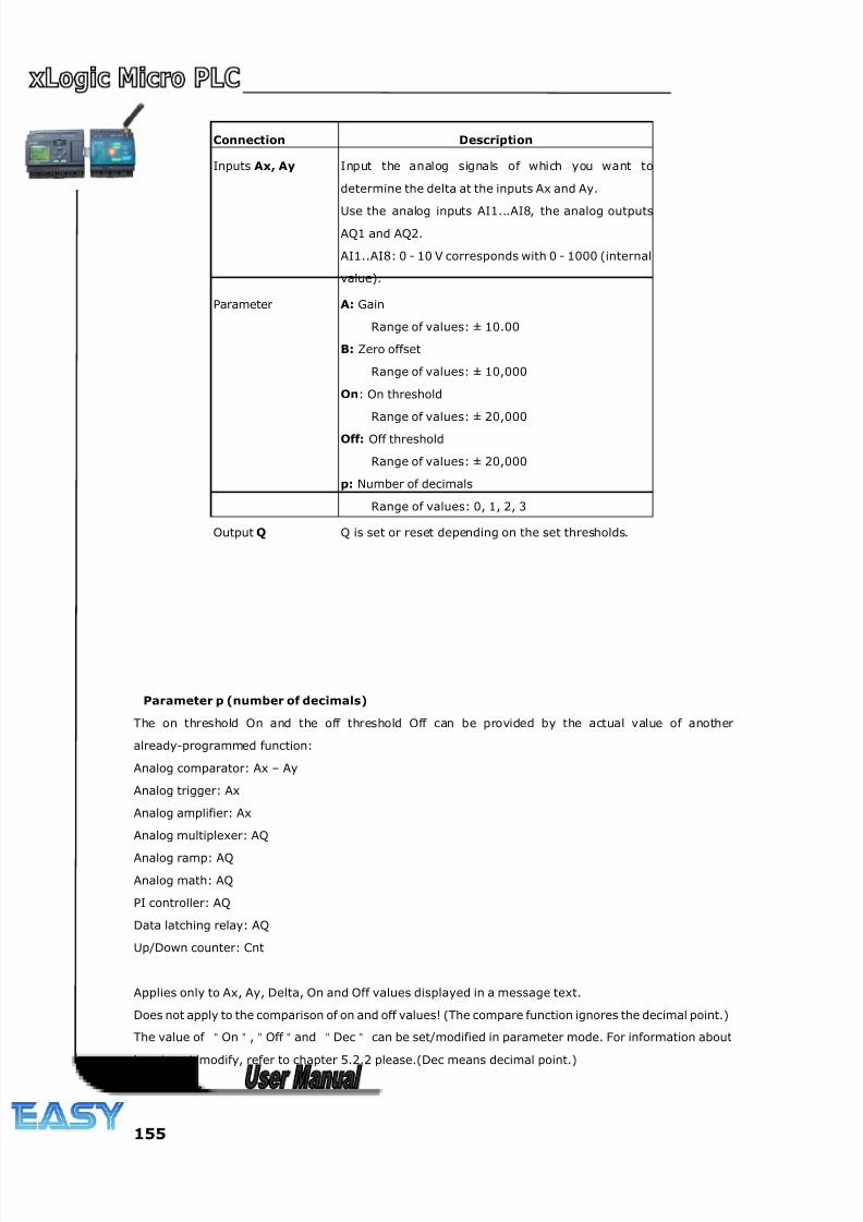
8/20/2019 XLogic User's Manual2
http://slidepdf.com/reader/full/xlogic-users-manual2 155/338
155
Connection Description
Inputs Ax, Ay Input the analog signals of which you want to
determine the delta at the inputs Ax and Ay.
Use the analog inputs AI1...AI8, the analog outputs
AQ1 and AQ2.
AI1..AI8: 0 - 10 V corresponds with 0 - 1000 (internal
value).
Parameter A: Gain
Range of values: ± 10.00
B: Zero offset
Range of values: ± 10,000
On: On threshold
Range of values: ± 20,000
Off: Off threshold
Range of values: ± 20,000
p: Number of decimals
Range of values: 0, 1, 2, 3
Output Q Q is set or reset depending on the set thresholds.
Parameter p (number of decimals)
The on threshold On and the off threshold Off can be provided by the actual value of another
already-programmed function:
Analog comparator: Ax – Ay
Analog trigger: Ax
Analog amplifier: Ax
Analog multiplexer: AQ
Analog ramp: AQ
Analog math: AQ
PI controller: AQ
Data latching relay: AQ
Up/Down counter: Cnt
Applies only to Ax, Ay, Delta, On and Off values displayed in a message text.
Does not apply to the comparison of on and off values! (The compare function ignores the decimal point.)
The value of "On","Off "and "Dec" can be set/modified in parameter mode. For information about
how to set/modify, refer to chapter 5.2.2 please.(Dec means decimal point.)
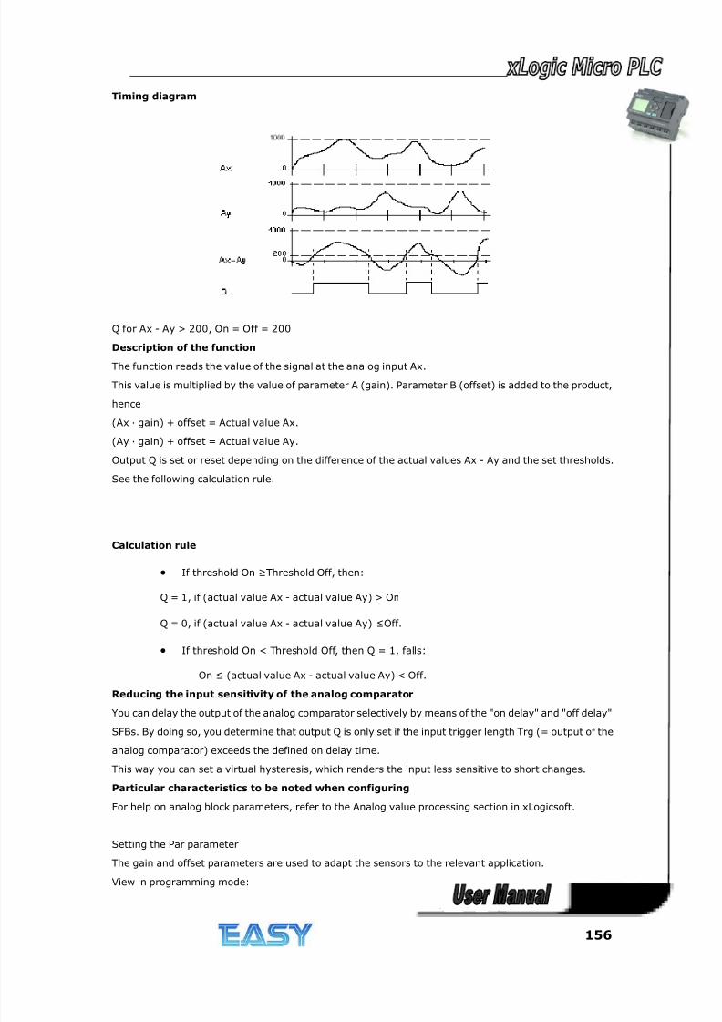
8/20/2019 XLogic User's Manual2
http://slidepdf.com/reader/full/xlogic-users-manual2 156/338
156
Timing diagram
Q for Ax - Ay > 200, On = Off = 200
Description of the function
The function reads the value of the signal at the analog input Ax.
This value is multiplied by the value of parameter A (gain). Parameter B (offset) is added to the product,
hence
(Ax · gain) + offset = Actual value Ax.
(Ay · gain) + offset = Actual value Ay.
Output Q is set or reset depending on the difference of the actual values Ax - Ay and the set thresholds.
See the following calculation rule.
Calculation rule
• If threshold On ≥Threshold Off, then:
Q = 1, if (actual value Ax - actual value Ay) > On
Q = 0, if (actual value Ax - actual value Ay) ≤Off.
• If threshold On < Threshold Off, then Q = 1, falls:
On ≤ (actual value Ax - actual value Ay) < Off.
Reducing the input sensitivity of the analog comparator
You can delay the output of the analog comparator selectively by means of the "on delay" and "off delay"
SFBs. By doing so, you determine that output Q is only set if the input trigger length Trg (= output of the
analog comparator) exceeds the defined on delay time.
This way you can set a virtual hysteresis, which renders the input less sensitive to short changes.
Particular characteristics to be noted when configuring
For help on analog block parameters, refer to the Analog value processing section in xLogicsoft.
Setting the Par parameter
The gain and offset parameters are used to adapt the sensors to the relevant application.
View in programming mode:
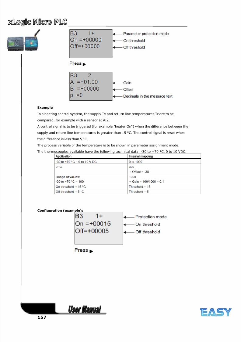
8/20/2019 XLogic User's Manual2
http://slidepdf.com/reader/full/xlogic-users-manual2 157/338
157
Example
In a heating control system, the supply Tv and return line temperatures Tr are to be
compared, for example with a sensor at AI2.
A control signal is to be triggered (for example "heater On") when the difference between the
supply and return line temperatures is greater than 15 °C. The control signal is reset when
the difference is less than 5 °C.
The process variable of the temperature is to be shown in parameter assignment mode.
The thermocouples available have the following technical data: -30 to +70 °C, 0 to 10 VDC.
Configuration (example):
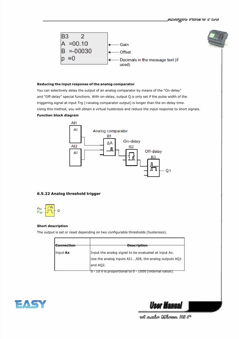
8/20/2019 XLogic User's Manual2
http://slidepdf.com/reader/full/xlogic-users-manual2 158/338
158
Reducing the input response of the analog comparator
You can selectively delay the output of an analog comparator by means of the "On-delay"
and "Off-delay" special functions. With on-delay, output Q is only set if the pulse width of the
triggering signal at input Trg (=analog comparator output) is longer than the on-delay time.
Using this method, you will obtain a virtual hysteresis and reduce the input response to short signals.
Function block diagram
6.5.22 Analog threshold trigger
Short description
The output is set or reset depending on two configurable thresholds (hysteresis).
Connection Description
Input Ax Input the analog signal to be evaluated at input Ax.
Use the analog inputs AI1...AI8, the analog outputs AQ1
and AQ2.
0 - 10 V is proportional to 0 - 1000 (internal value).
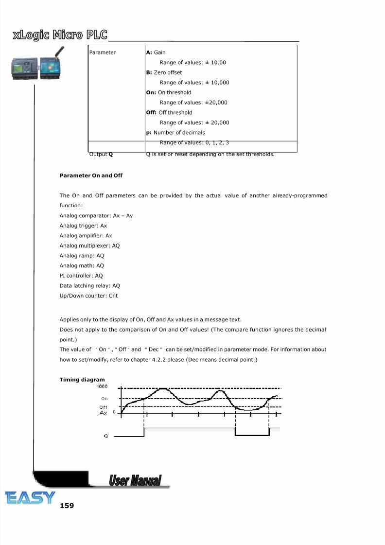
8/20/2019 XLogic User's Manual2
http://slidepdf.com/reader/full/xlogic-users-manual2 159/338
159
Parameter A: Gain
Range of values: ± 10.00
B: Zero offset
Range of values: ± 10,000
On: On thresholdRange of values: ±20,000
Off: Off threshold
Range of values: ± 20,000
p: Number of decimals
Range of values: 0, 1, 2, 3
Output Q Q is set or reset depending on the set thresholds.
Parameter On and Off
The On and Off parameters can be provided by the actual value of another already-programmed
function:
Analog comparator: Ax – Ay
Analog trigger: Ax
Analog amplifier: Ax
Analog multiplexer: AQ
Analog ramp: AQ
Analog math: AQ
PI controller: AQ
Data latching relay: AQ
Up/Down counter: Cnt
Applies only to the display of On, Off and Ax values in a message text.
Does not apply to the comparison of On and Off values! (The compare function ignores the decimal
point.)
The value of "On","Off "and "Dec" can be set/modified in parameter mode. For information about
how to set/modify, refer to chapter 4.2.2 please.(Dec means decimal point.)
Timing diagram
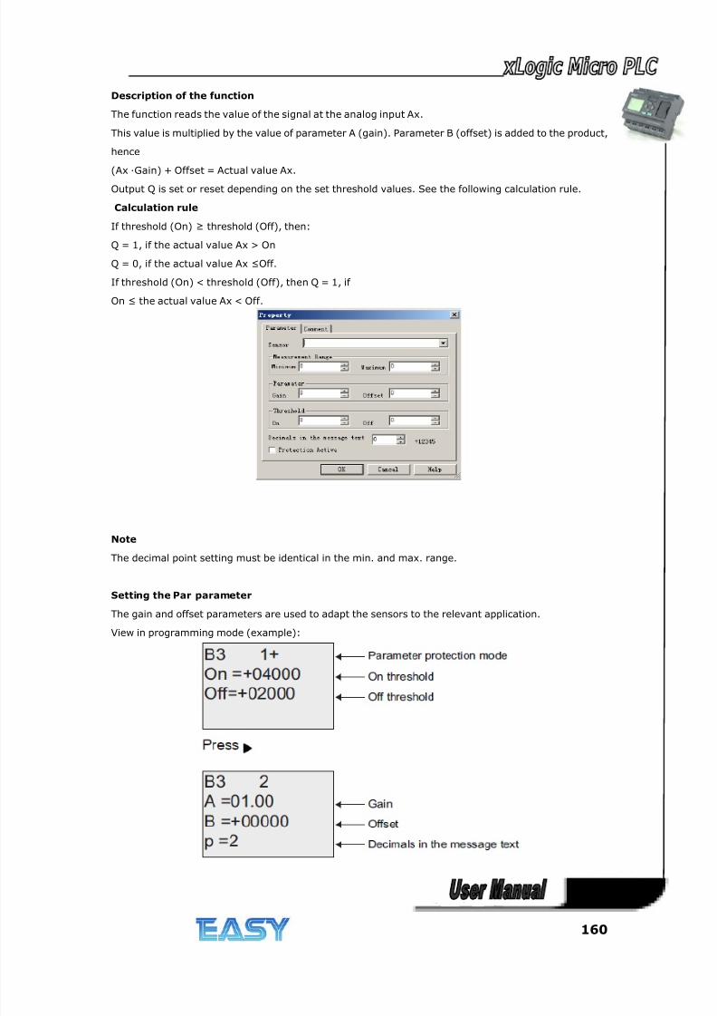
8/20/2019 XLogic User's Manual2
http://slidepdf.com/reader/full/xlogic-users-manual2 160/338
160
Description of the function
The function reads the value of the signal at the analog input Ax.
This value is multiplied by the value of parameter A (gain). Parameter B (offset) is added to the product,
hence
(Ax ·Gain) + Offset = Actual value Ax.
Output Q is set or reset depending on the set threshold values. See the following calculation rule.
Calculation rule
If threshold (On) ≥ threshold (Off), then:
Q = 1, if the actual value Ax > On
Q = 0, if the actual value Ax ≤Off.
If threshold (On) < threshold (Off), then Q = 1, if
On ≤ the actual value Ax < Off.
Note
The decimal point setting must be identical in the min. and max. range.
Setting the Par parameter
The gain and offset parameters are used to adapt the sensors to the relevant application.
View in programming mode (example):
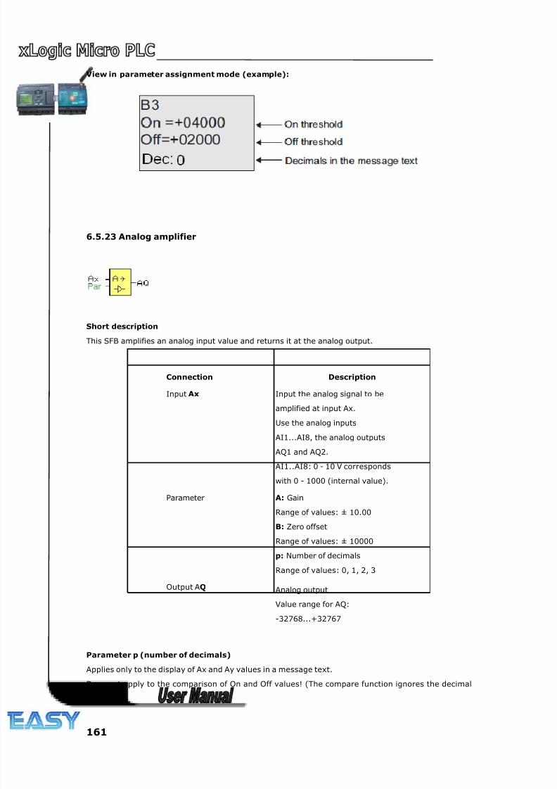
8/20/2019 XLogic User's Manual2
http://slidepdf.com/reader/full/xlogic-users-manual2 161/338
161
View in parameter assignment mode (example):
6.5.23 Analog amplifier
Short description
This SFB amplifies an analog input value and returns it at the analog output.
Connection Description
Input Ax Input the analog signal to be
amplified at input Ax.
Use the analog inputs
AI1...AI8, the analog outputs
AQ1 and AQ2.
AI1..AI8: 0 - 10 V corresponds
with 0 - 1000 (internal value).
Parameter A: Gain
Range of values: ± 10.00
B: Zero offset
Range of values: ± 10000
p: Number of decimals
Range of values: 0, 1, 2, 3
Output AQ Analog output
Value range for AQ:
-32768...+32767
Parameter p (number of decimals)
Applies only to the display of Ax and Ay values in a message text.
Does not apply to the comparison of On and Off values! (The compare function ignores the decimal
point.)
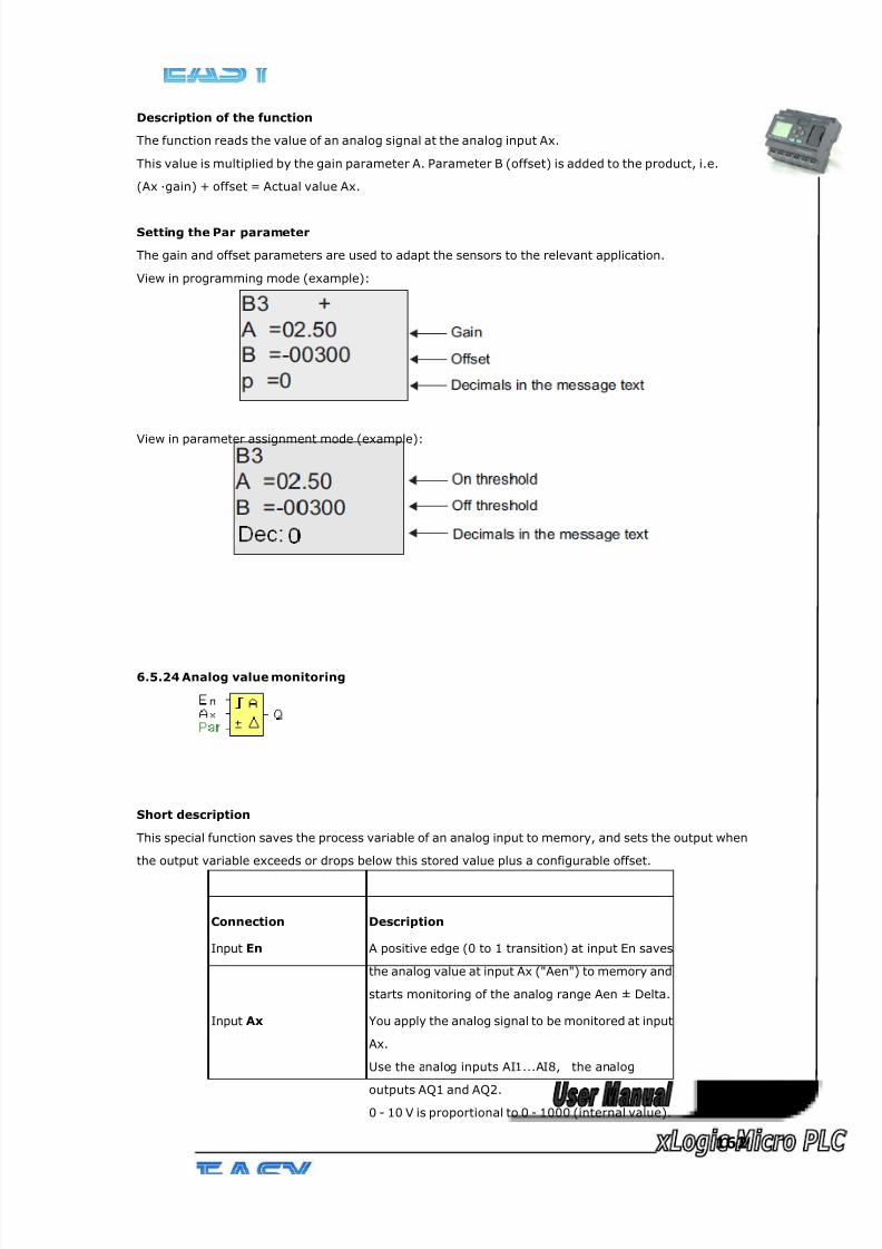
8/20/2019 XLogic User's Manual2
http://slidepdf.com/reader/full/xlogic-users-manual2 162/338
162
Description of the function
The function reads the value of an analog signal at the analog input Ax.
This value is multiplied by the gain parameter A. Parameter B (offset) is added to the product, i.e.
(Ax ·gain) + offset = Actual value Ax.
Setting the Par parameter
The gain and offset parameters are used to adapt the sensors to the relevant application.
View in programming mode (example):
View in parameter assignment mode (example):
6.5.24 Analog value monitoring
Short description
This special function saves the process variable of an analog input to memory, and sets the output when
the output variable exceeds or drops below this stored value plus a configurable offset.
Connection Description
Input En A positive edge (0 to 1 transition) at input En saves
the analog value at input Ax ("Aen") to memory and
starts monitoring of the analog range Aen ± Delta.
Input Ax You apply the analog signal to be monitored at input
Ax.
Use the analog inputs AI1...AI8, the analog
outputs AQ1 and AQ2.0 - 10 V is proportional to 0 - 1000 (internal value).
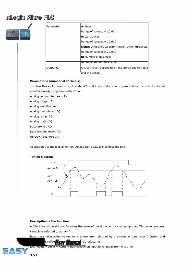
8/20/2019 XLogic User's Manual2
http://slidepdf.com/reader/full/xlogic-users-manual2 163/338
163
Parameter p (number of decimals)
The two threshold parameters Threshold 1 and Threshold 2 can be provided by the actual value of
another already-programmed function:
Analog comparator: Ax – Ay
Analog trigger: Ax
Analog amplifier: Ax
Analog multiplexer: AQ
Analog ramp: AQ
Analog math: AQ
PI controller: AQ
Data latching relay: AQ
Up/Down counter: Cnt
Applies only to the display of Aen, Ax and Delta values in a message text.
Timing diagram
Description of the function
A 0 to 1 transition at input En saves the value of the signal at the analog input Ax. This saved process
variable is referred to as Aen".
Both the analog actual values Ax and Aen are multiplied by the value at parameter A (gain), and
parameter B (offset) is then added to the product, i.e.
(Ax · gain) + offset = Actual value Aen, when input En changes from 0 to 1, or
Parameter A: Gain
Range of values: ± 10.00
B: Zero offset
Range of values: ± 10,000
Delta: Difference value for the Aen on/off thresholdRange of values: ± 20,000
p: Number of decimals
Range of values: 0, 1, 2, 3
Output Q Q is set/reset, depending on the stored analog value
and the offset.
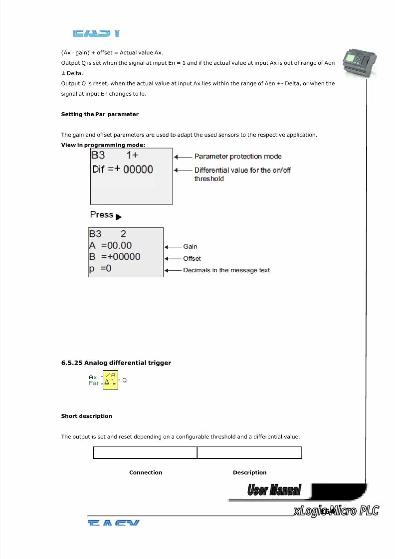
8/20/2019 XLogic User's Manual2
http://slidepdf.com/reader/full/xlogic-users-manual2 164/338
164
(Ax · gain) + offset = Actual value Ax.
Output Q is set when the signal at input En = 1 and if the actual value at input Ax is out of range of Aen
± Delta.
Output Q is reset, when the actual value at input Ax lies within the range of Aen +- Delta, or when the
signal at input En changes to lo.
Setting the Par parameter
The gain and offset parameters are used to adapt the used sensors to the respective application.
View in programming mode:
6.5.25 Analog differential trigger
Short description
The output is set and reset depending on a configurable threshold and a differential value.
Connection Description
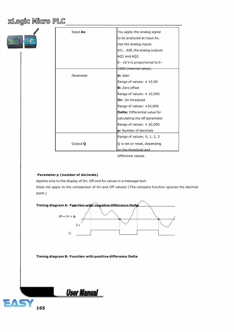
8/20/2019 XLogic User's Manual2
http://slidepdf.com/reader/full/xlogic-users-manual2 165/338
165
Input Ax You apply the analog signal
to be analyzed at input Ax.
Use the analog inputs
AI1...AI8, the analog outputs
AQ1 and AQ2.0 - 10 V is proportional to 0 -
1000 (internal value).
Parameter A: Gain
Range of values: ± 10.00
B: Zero offset
Range of values: ± 10,000
On: On threshold
Range of values: ±20,000
Delta: Differential value for
calculating the off parameter
Range of values: ± 20,000
p: Number of decimals
Range of values: 0, 1, 2, 3
Output Q Q is set or reset, depending
on the threshold and
difference values.
Parameter p (number of decimals)
Applies only to the display of On, Off and Ax values in a message text.
Does not apply to the comparison of On and Off values! (The compare function ignores the decimal
point.)
Timing diagram A: Function with negative difference Delta
Timing diagram B: Function with positive difference Delta
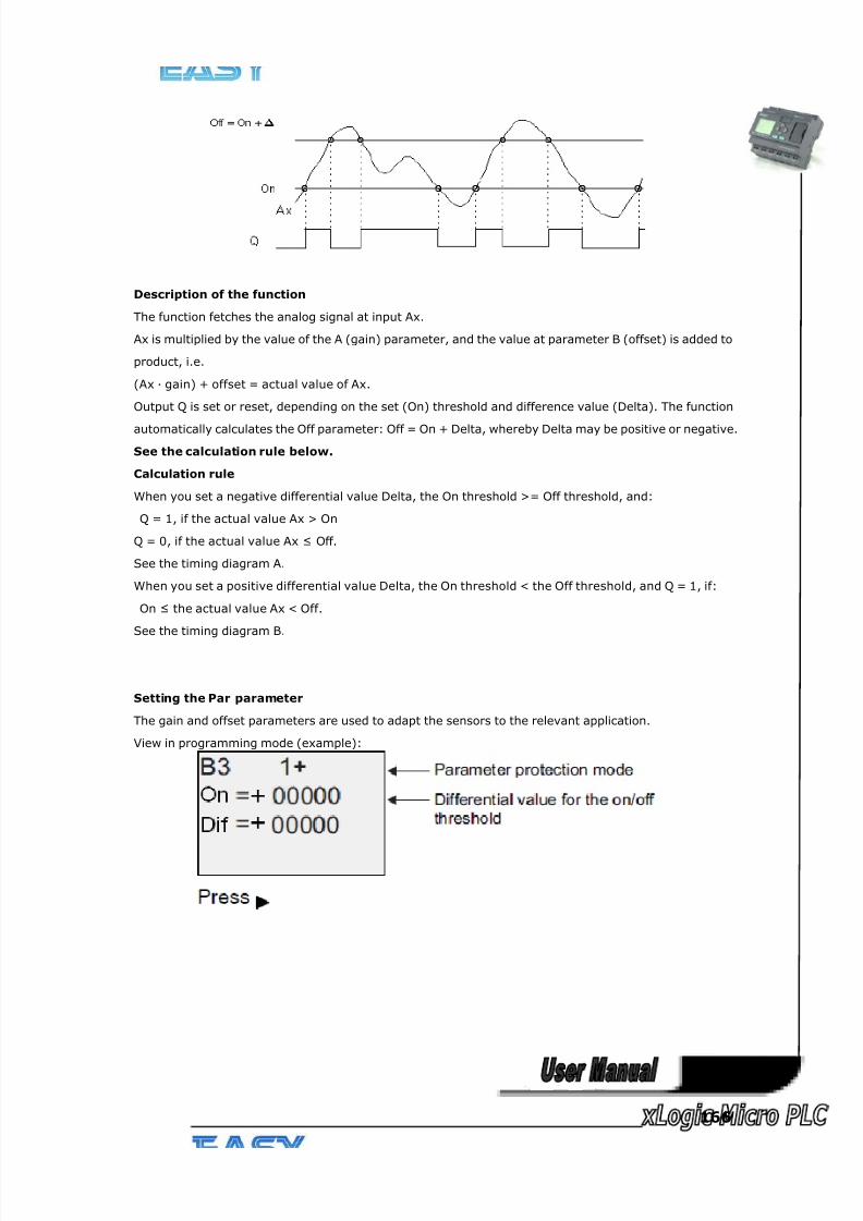
8/20/2019 XLogic User's Manual2
http://slidepdf.com/reader/full/xlogic-users-manual2 166/338
166
Description of the function
The function fetches the analog signal at input Ax.
Ax is multiplied by the value of the A (gain) parameter, and the value at parameter B (offset) is added to
product, i.e.
(Ax · gain) + offset = actual value of Ax.
Output Q is set or reset, depending on the set (On) threshold and difference value (Delta). The function
automatically calculates the Off parameter: Off = On + Delta, whereby Delta may be positive or negative.
See the calculation rule below.
Calculation rule
When you set a negative differential value Delta, the On threshold >= Off threshold, and:
Q = 1, if the actual value Ax > On
Q = 0, if the actual value Ax ≤ Off.
See the timing diagram A.
When you set a positive differential value Delta, the On threshold < the Off threshold, and Q = 1, if:
On ≤ the actual value Ax < Off.
See the timing diagram B.
Setting the Par parameter
The gain and offset parameters are used to adapt the sensors to the relevant application.
View in programming mode (example):
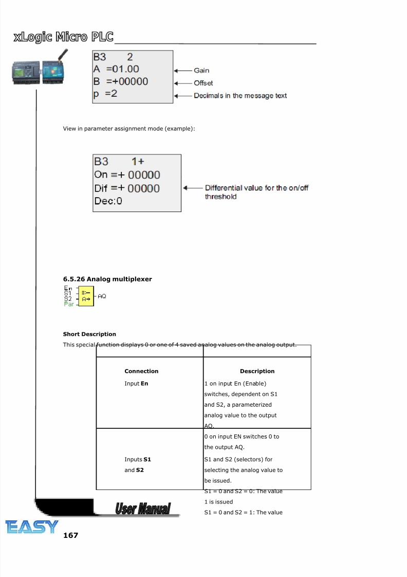
8/20/2019 XLogic User's Manual2
http://slidepdf.com/reader/full/xlogic-users-manual2 167/338
167
View in parameter assignment mode (example):
6.5.26 Analog multiplexer
Short Description
This special function displays 0 or one of 4 saved analog values on the analog output.
Connection Description
Input En 1 on input En (Enable)
switches, dependent on S1
and S2, a parameterized
analog value to the output
AQ.
0 on input EN switches 0 to
the output AQ.
Inputs S1
and S2
S1 and S2 (selectors) for
selecting the analog value to
be issued.
S1 = 0 and S2 = 0: The value
1 is issuedS1 = 0 and S2 = 1: The value
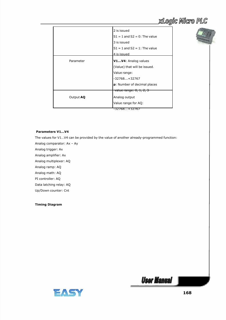
8/20/2019 XLogic User's Manual2
http://slidepdf.com/reader/full/xlogic-users-manual2 168/338
168
2 is issued
S1 = 1 and S2 = 0: The value
3 is issued
S1 = 1 and S2 = 1: The value
4 is issued
Parameter V1...V4: Analog values
(Value) that will be issued.
Value range:
-32768...+32767
p: Number of decimal places
value range: 0, 1, 2, 3
Output AQ Analog output
Value range for AQ:
-32768...+32767
Parameters V1…V4
The values for V1…V4 can be provided by the value of another already-programmed function:
Analog comparator: Ax – Ay
Analog trigger: Ax
Analog amplifier: Ax
Analog multiplexer: AQ
Analog ramp: AQAnalog math: AQ
PI controller: AQ
Data latching relay: AQ
Up/Down counter: Cnt
Timing Diagram
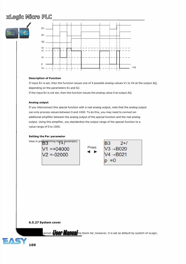
8/20/2019 XLogic User's Manual2
http://slidepdf.com/reader/full/xlogic-users-manual2 169/338
169
Description of Function
If input En is set, then the function issues one of 4 possible analog values V1 to V4 at the output AQ,
depending on the parameters S1 and S2.
If the input En is not set, then the function issues the analog value 0 at output AQ.
Analog output
If you interconnect this special function with a real analog output, note that the analog output
can only process values between 0 and 1000. To do this, you may need to connect an
additional amplifier between the analog output of the special function and the real analog
output. Using this amplifier, you standardize the output range of the special function to a
value range of 0 to 1000.
Setting the Par parameter
View in programming mode (example):
6.5.27 System cover
This block cannot directly be found in the block list ,however, it is set as default by system of xLogic,
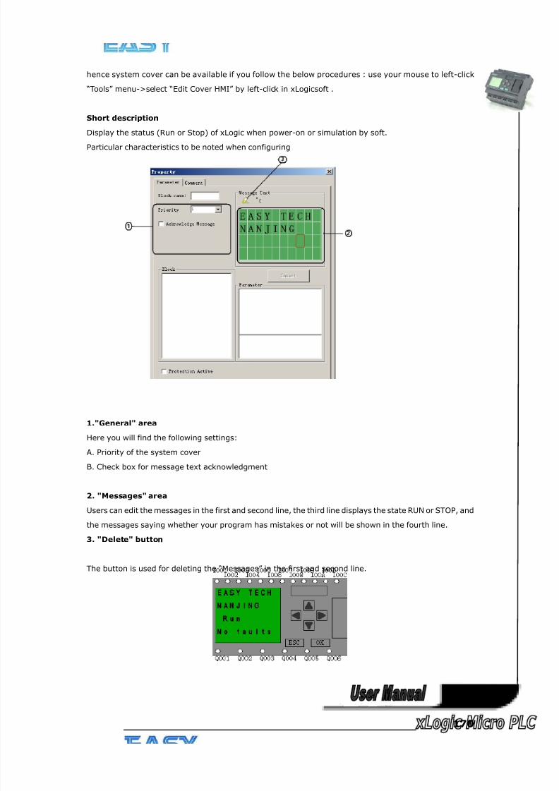
8/20/2019 XLogic User's Manual2
http://slidepdf.com/reader/full/xlogic-users-manual2 170/338
170
hence system cover can be available if you follow the below procedures : use your mouse to left-click
“Tools” menu->select “Edit Cover HMI” by left-click in xLogicsoft .
Short description
Display the status (Run or Stop) of xLogic when power-on or simulation by soft.
Particular characteristics to be noted when configuring
1."General" area
Here you will find the following settings:
A. Priority of the system cover
B. Check box for message text acknowledgment
2. "Messages" area
Users can edit the messages in the first and second line, the third line displays the state RUN or STOP, and
the messages saying whether your program has mistakes or not will be shown in the fourth line.
3. "Delete" button
The button is used for deleting the “Messages” in the first and second line.
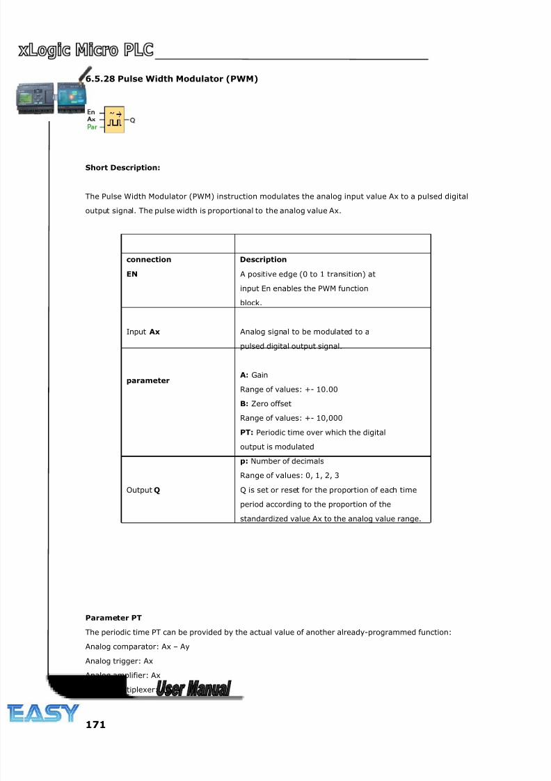
8/20/2019 XLogic User's Manual2
http://slidepdf.com/reader/full/xlogic-users-manual2 171/338
171
6.5.28 Pulse Width Modulator (PWM)
Short Description:
The Pulse Width Modulator (PWM) instruction modulates the analog input value Ax to a pulsed digital
output signal. The pulse width is proportional to the analog value Ax.
connection Description
EN A positive edge (0 to 1 transition) at
input En enables the PWM function
block.
Input Ax Analog signal to be modulated to a
pulsed digital output signal.
parameter A: Gain
Range of values: +- 10.00
B: Zero offset
Range of values: +- 10,000
PT: Periodic time over which the digital
output is modulated
p: Number of decimals
Range of values: 0, 1, 2, 3
Output Q Q is set or reset for the proportion of each time
period according to the proportion of the
standardized value Ax to the analog value range.
Parameter PT
The periodic time PT can be provided by the actual value of another already-programmed function:
Analog comparator: Ax – Ay
Analog trigger: Ax
Analog amplifier: Ax
Analog multiplexer: AQ
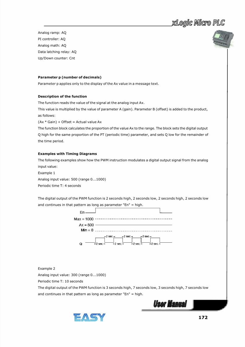
8/20/2019 XLogic User's Manual2
http://slidepdf.com/reader/full/xlogic-users-manual2 172/338
172
Analog ramp: AQ
PI controller: AQ
Analog math: AQ
Data latching relay: AQ
Up/Down counter: Cnt
Parameter p (number of decimals)
Parameter p applies only to the display of the Ax value in a message text.
Description of the function
The function reads the value of the signal at the analog input Ax.
This value is multiplied by the value of parameter A (gain). Parameter B (offset) is added to the product,
as follows:
(Ax * Gain) + Offset = Actual value Ax
The function block calculates the proportion of the value Ax to the range. The block sets the digital output
Q high for the same proportion of the PT (periodic time) parameter, and sets Q low for the remainder of
the time period.
Examples with Timing Diagrams
The following examples show how the PWM instruction modulates a digital output signal from the analog
input value:
Example 1
Analog input value: 500 (range 0...1000)
Periodic time T: 4 seconds
The digital output of the PWM function is 2 seconds high, 2 seconds low, 2 seconds high, 2 seconds low
and continues in that pattern as long as parameter "En" = high.
Example 2
Analog input value: 300 (range 0...1000)
Periodic time T: 10 seconds
The digital output of the PWM function is 3 seconds high, 7 seconds low, 3 seconds high, 7 seconds low
and continues in that pattern as long as parameter "En" = high.
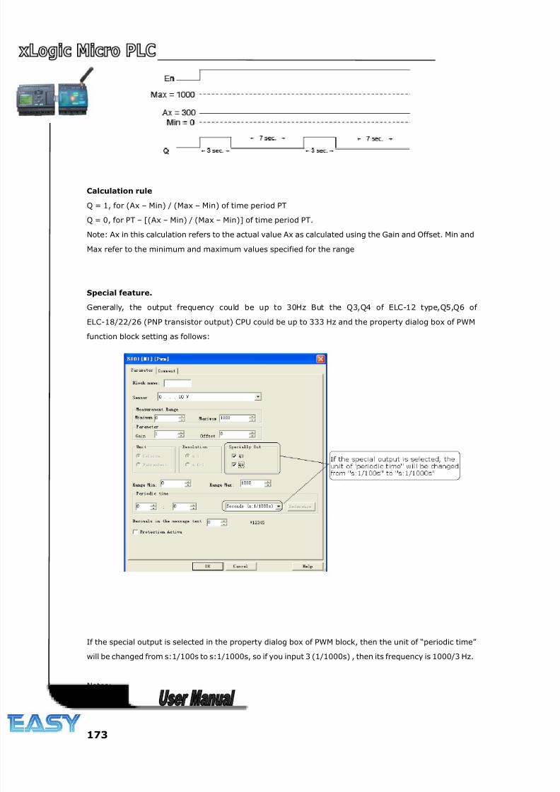
8/20/2019 XLogic User's Manual2
http://slidepdf.com/reader/full/xlogic-users-manual2 173/338
173
Calculation rule
Q = 1, for (Ax – Min) / (Max – Min) of time period PT
Q = 0, for PT – [(Ax – Min) / (Max – Min)] of time period PT.
Note: Ax in this calculation refers to the actual value Ax as calculated using the Gain and Offset. Min and
Max refer to the minimum and maximum values specified for the range
Special feature.
Generally, the output frequency could be up to 30Hz But the Q3,Q4 of ELC-12 type,Q5,Q6 of
ELC-18/22/26 (PNP transistor output) CPU could be up to 333 Hz and the property dialog box of PWM
function block setting as follows:
If the special output is selected in the property dialog box of PWM block, then the unit of “periodic time”
will be changed from s:1/100s to s:1/1000s, so if you input 3 (1/1000s) , then its frequency is 1000/3 Hz.
Notes:
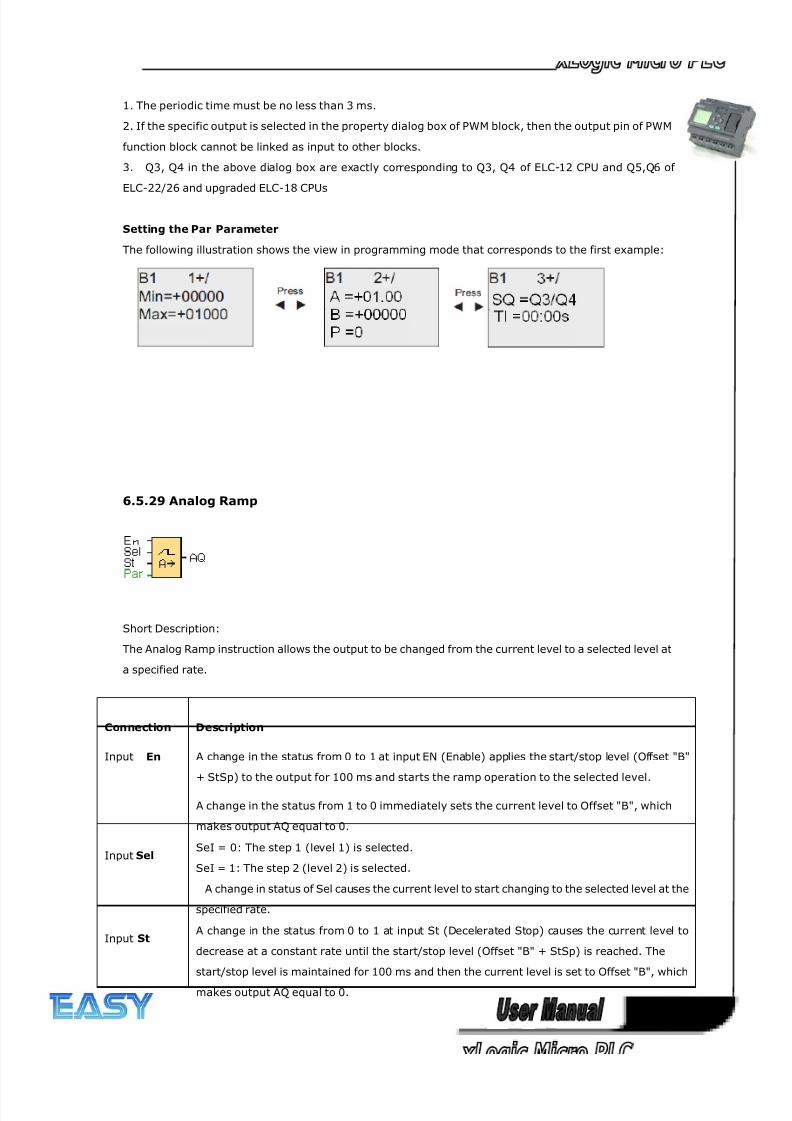
8/20/2019 XLogic User's Manual2
http://slidepdf.com/reader/full/xlogic-users-manual2 174/338
174
1. The periodic time must be no less than 3 ms.
2. If the specific output is selected in the property dialog box of PWM block, then the output pin of PWM
function block cannot be linked as input to other blocks.
3. Q3, Q4 in the above dialog box are exactly corresponding to Q3, Q4 of ELC-12 CPU and Q5,Q6 of
ELC-22/26 and upgraded ELC-18 CPUs
Setting the Par Parameter
The following illustration shows the view in programming mode that corresponds to the first example:
6.5.29 Analog Ramp
Short Description:
The Analog Ramp instruction allows the output to be changed from the current level to a selected level at
a specified rate.
Connection Description
Input En A change in the status from 0 to 1 at input EN (Enable) applies the start/stop level (Offset "B"
+ StSp) to the output for 100 ms and starts the ramp operation to the selected level.
A change in the status from 1 to 0 immediately sets the current level to Offset "B", which
makes output AQ equal to 0.
Input Sel SeI = 0: The step 1 (level 1) is selected.
SeI = 1: The step 2 (level 2) is selected.
A change in status of Sel causes the current level to start changing to the selected level at the
specified rate.
Input St A change in the status from 0 to 1 at input St (Decelerated Stop) causes the current level to
decrease at a constant rate until the start/stop level (Offset "B" + StSp) is reached. The
start/stop level is maintained for 100 ms and then the current level is set to Offset "B", which
makes output AQ equal to 0.
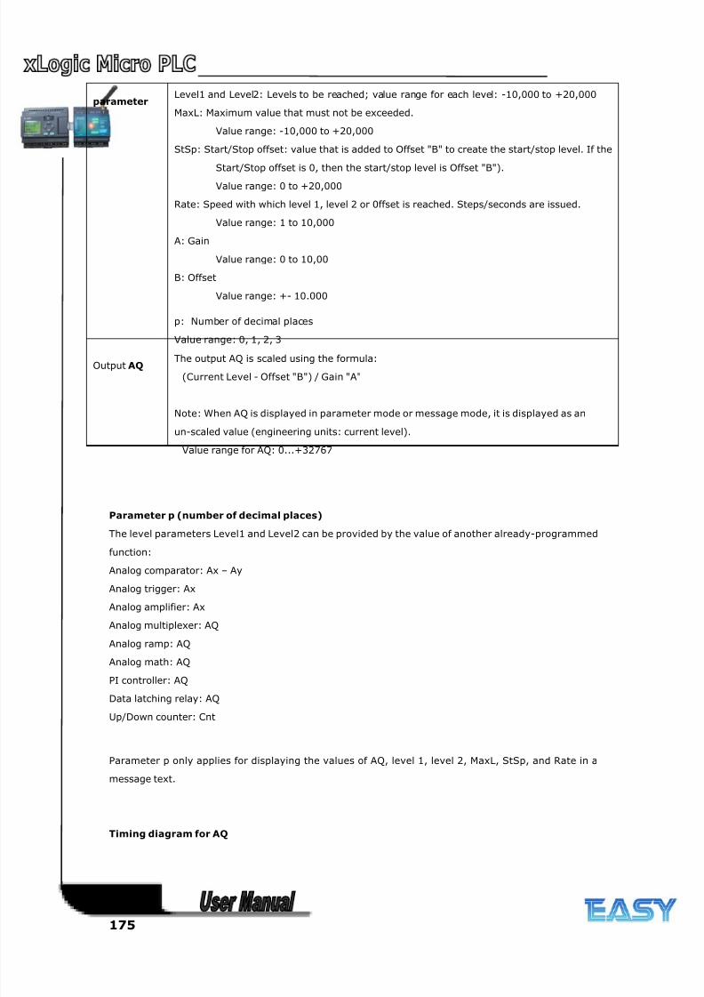
8/20/2019 XLogic User's Manual2
http://slidepdf.com/reader/full/xlogic-users-manual2 175/338
175
parameter Level1 and Level2: Levels to be reached; value range for each level: -10,000 to +20,000
MaxL: Maximum value that must not be exceeded.
Value range: -10,000 to +20,000
StSp: Start/Stop offset: value that is added to Offset "B" to create the start/stop level. If the
Start/Stop offset is 0, then the start/stop level is Offset "B").
Value range: 0 to +20,000
Rate: Speed with which level 1, level 2 or 0ffset is reached. Steps/seconds are issued.
Value range: 1 to 10,000
A: Gain
Value range: 0 to 10,00
B: Offset
Value range: +- 10.000
p: Number of decimal places
Value range: 0, 1, 2, 3
Output AQ The output AQ is scaled using the formula:
(Current Level - Offset "B") / Gain "A"
Note: When AQ is displayed in parameter mode or message mode, it is displayed as an
un-scaled value (engineering units: current level).
Value range for AQ: 0...+32767
Parameter p (number of decimal places)
The level parameters Level1 and Level2 can be provided by the value of another already-programmed
function:
Analog comparator: Ax – Ay
Analog trigger: Ax
Analog amplifier: Ax
Analog multiplexer: AQ
Analog ramp: AQ
Analog math: AQ
PI controller: AQ
Data latching relay: AQ
Up/Down counter: Cnt
Parameter p only applies for displaying the values of AQ, level 1, level 2, MaxL, StSp, and Rate in a
message text.
Timing diagram for AQ
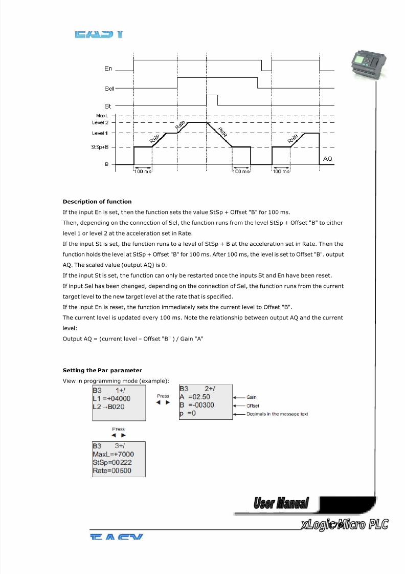
8/20/2019 XLogic User's Manual2
http://slidepdf.com/reader/full/xlogic-users-manual2 176/338
176
Description of function
If the input En is set, then the function sets the value StSp + Offset "B" for 100 ms.
Then, depending on the connection of Sel, the function runs from the level StSp + Offset "B" to either
level 1 or level 2 at the acceleration set in Rate.
If the input St is set, the function runs to a level of StSp + B at the acceleration set in Rate. Then the
function holds the level at StSp + Offset "B" for 100 ms. After 100 ms, the level is set to Offset "B". output
AQ. The scaled value (output AQ) is 0.
If the input St is set, the function can only be restarted once the inputs St and En have been reset.
If input Sel has been changed, depending on the connection of Sel, the function runs from the current
target level to the new target level at the rate that is specified.
If the input En is reset, the function immediately sets the current level to Offset "B".
The current level is updated every 100 ms. Note the relationship between output AQ and the current
level:
Output AQ = (current level – Offset "B" ) / Gain "A"
Setting the Par parameter
View in programming mode (example):
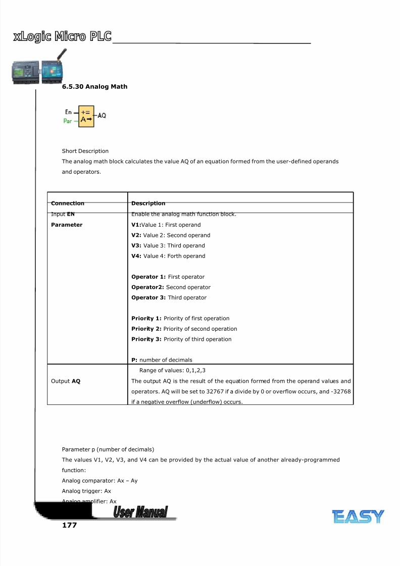
8/20/2019 XLogic User's Manual2
http://slidepdf.com/reader/full/xlogic-users-manual2 177/338
177
6.5.30 Analog Math
Short Description
The analog math block calculates the value AQ of an equation formed from the user-defined operands
and operators.
Connection Description
Input EN Enable the analog math function block.
Parameter V1:Value 1: First operand
V2: Value 2: Second operand
V3: Value 3: Third operand
V4: Value 4: Forth operand
Operator 1: First operator
Operator2: Second operator
Operator 3: Third operator
Priority 1: Priority of first operation
Priority 2: Priority of second operation
Priority 3: Priority of third operation
P: number of decimals
Range of values: 0,1,2,3
Output AQ The output AQ is the result of the equation formed from the operand values and
operators. AQ will be set to 32767 if a divide by 0 or overflow occurs, and -32768
if a negative overflow (underflow) occurs.
Parameter p (number of decimals)
The values V1, V2, V3, and V4 can be provided by the actual value of another already-programmed
function:
Analog comparator: Ax – Ay
Analog trigger: Ax
Analog amplifier: Ax
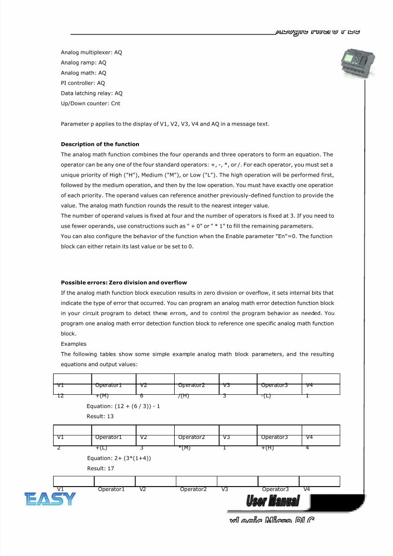
8/20/2019 XLogic User's Manual2
http://slidepdf.com/reader/full/xlogic-users-manual2 178/338
178
Analog multiplexer: AQ
Analog ramp: AQ
Analog math: AQ
PI controller: AQ
Data latching relay: AQ
Up/Down counter: Cnt
Parameter p applies to the display of V1, V2, V3, V4 and AQ in a message text.
Description of the function
The analog math function combines the four operands and three operators to form an equation. The
operator can be any one of the four standard operators: +, -, *, or /. For each operator, you must set a
unique priority of High ("H"), Medium ("M"), or Low ("L"). The high operation will be performed first,
followed by the medium operation, and then by the low operation. You must have exactly one operation
of each priority. The operand values can reference another previously-defined function to provide the
value. The analog math function rounds the result to the nearest integer value.
The number of operand values is fixed at four and the number of operators is fixed at 3. If you need to
use fewer operands, use constructions such as " + 0" or " * 1" to fill the remaining parameters.
You can also configure the behavior of the function when the Enable parameter "En"=0. The function
block can either retain its last value or be set to 0.
Possible errors: Zero division and overflow
If the analog math function block execution results in zero division or overflow, it sets internal bits that
indicate the type of error that occurred. You can program an analog math error detection function block
in your circuit program to detect these errors, and to control the program behavior as needed. You
program one analog math error detection function block to reference one specific analog math function
block.
Examples
The following tables show some simple example analog math block parameters, and the resulting
equations and output values:
V1 Operator1 V2 Operator2 V3 Operator3 V4
12 +(M) 6 /(H) 3 -(L) 1
Equation: (12 + (6 / 3)) - 1
Result: 13
V1 Operator1 V2 Operator2 V3 Operator3 V4
2 +(L) 3 *(M) 1 +(H) 4
Equation: 2+ (3*(1+4))
Result: 17
V1 Operator1 V2 Operator2 V3 Operator3 V4
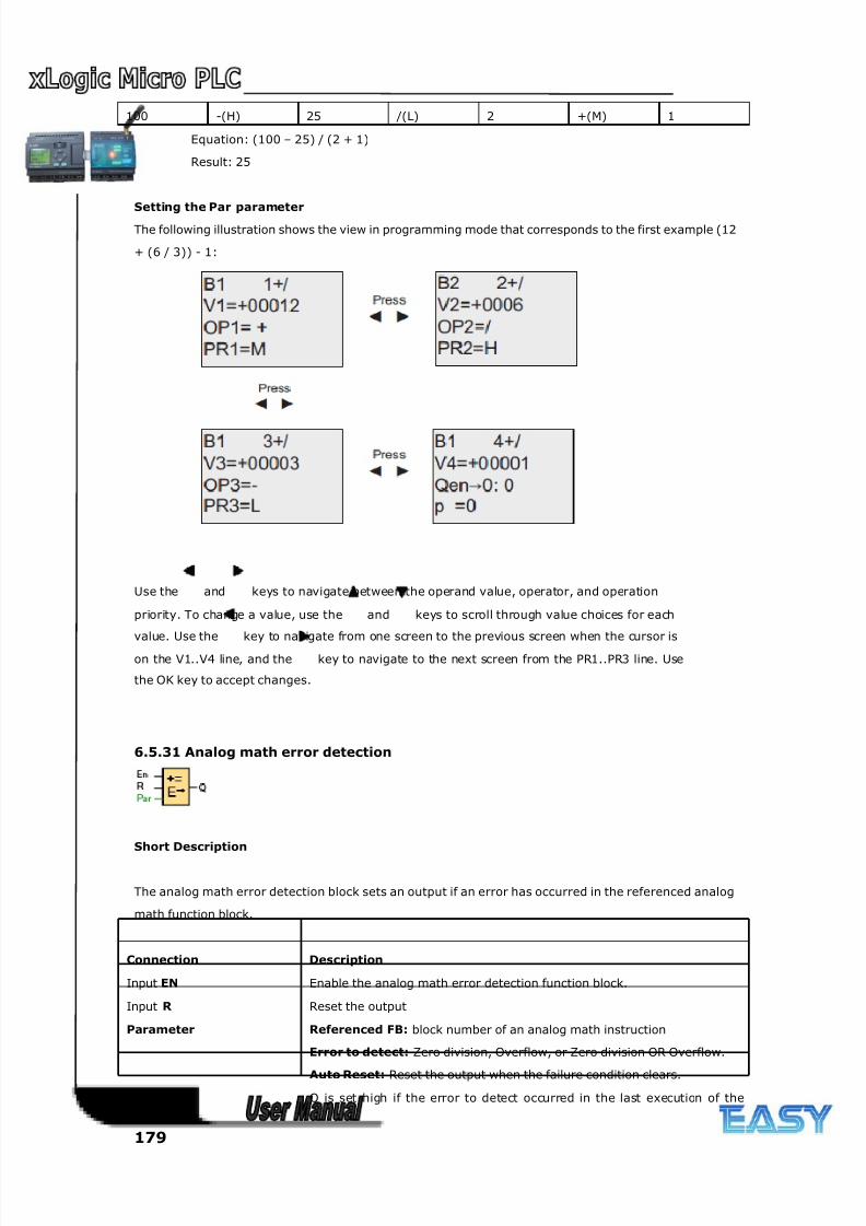
8/20/2019 XLogic User's Manual2
http://slidepdf.com/reader/full/xlogic-users-manual2 179/338
179
100 -(H) 25 /(L) 2 +(M) 1
Equation: (100 – 25) / (2 + 1)
Result: 25
Setting the Par parameter
The following illustration shows the view in programming mode that corresponds to the first example (12
+ (6 / 3)) - 1:
Use the and keys to navigate between the operand value, operator, and operation
priority. To change a value, use the and keys to scroll through value choices for each
value. Use the key to navigate from one screen to the previous screen when the cursor is
on the V1..V4 line, and the key to navigate to the next screen from the PR1..PR3 line. Use
the OK key to accept changes.
6.5.31 Analog math error detection
Short Description
The analog math error detection block sets an output if an error has occurred in the referenced analog
math function block.
Connection Description
Input EN Enable the analog math error detection function block.
Input R Reset the output
Parameter Referenced FB: block number of an analog math instruction
Error to detect: Zero division, Overflow, or Zero division OR Overflow.
Auto Reset: Reset the output when the failure condition clears.
Output AQ Q is set high if the error to detect occurred in the last execution of the
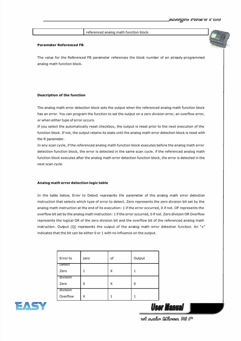
8/20/2019 XLogic User's Manual2
http://slidepdf.com/reader/full/xlogic-users-manual2 180/338
180
referenced analog math function block.
Parameter Referenced FB
The value for the Referenced FB parameter references the block number of an already-programmed
analog math function block.
Description of the function
The analog math error detection block sets the output when the referenced analog math function block
has an error. You can program the function to set the output on a zero division error, an overflow error,
or when either type of error occurs.
If you select the automatically reset checkbox, the output is reset prior to the next execution of the
function block. If not, the output retains its state until the analog math error detection block is reset with
the R parameter.
In any scan cycle, if the referenced analog math function block executes before the analog math error
detection function block, the error is detected in the same scan cycle. if the referenced analog math
function block executes after the analog math error detection function block, the error is detected in the
next scan cycle.
Analog math error detection logic table
In the table below, Error to Detect represents the parameter of the analog math error detection
instruction that selects which type of error to detect. Zero represents the zero division bit set by the
analog math instruction at the end of its execution: 1 if the error occurred, 0 if not. OF represents the
overflow bit set by the analog math instruction: 1 if the error occurred, 0 if not. Zero division OR Overflow
represents the logical OR of the zero division bit and the overflow bit of the referenced analog math
instruction. Output (Q) represents the output of the analog math error detection function. An “x”
indicates that the bit can be either 0 or 1 with no influence on the output.
Error to
Detect
zero of Output
Zero
division
1 X 1
Zero
division
0 X 0
Overflow X 1 1
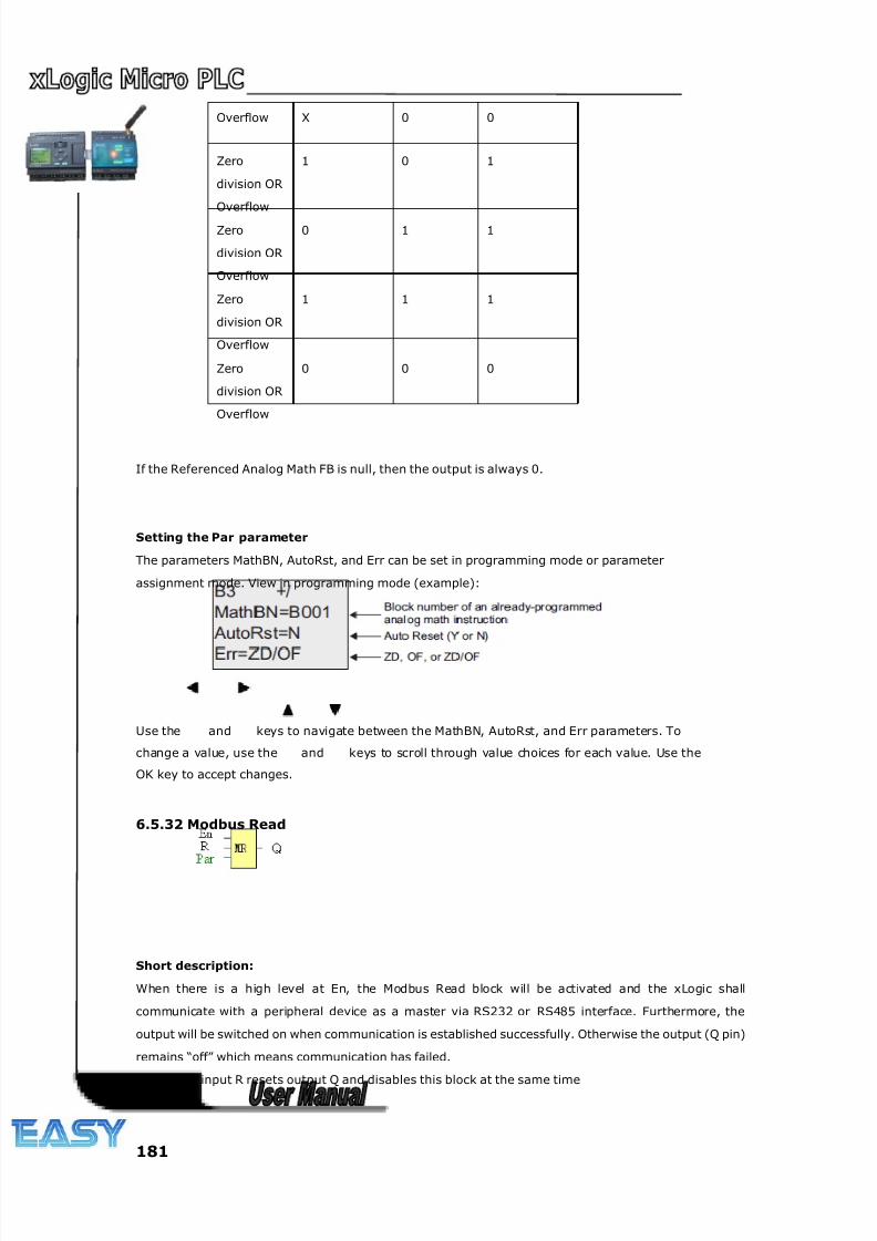
8/20/2019 XLogic User's Manual2
http://slidepdf.com/reader/full/xlogic-users-manual2 181/338
181
Overflow X 0 0
Zero
division OR
Overflow
1 0 1
Zero
division OR
Overflow
0 1 1
Zero
division OR
Overflow
1 1 1
Zero
division OR
Overflow
0 0 0
If the Referenced Analog Math FB is null, then the output is always 0.
Setting the Par parameter
The parameters MathBN, AutoRst, and Err can be set in programming mode or parameter
assignment mode. View in programming mode (example):
Use the and keys to navigate between the MathBN, AutoRst, and Err parameters. To
change a value, use the and keys to scroll through value choices for each value. Use the
OK key to accept changes.
6.5.32 Modbus Read
Short description:
When there is a high level at En, the Modbus Read block will be activated and the xLogic shall
communicate with a peripheral device as a master via RS232 or RS485 interface. Furthermore, the
output will be switched on when communication is established successfully. Otherwise the output (Q pin)
remains “off” which means communication has failed.
A signal at input R resets output Q and disables this block at the same time
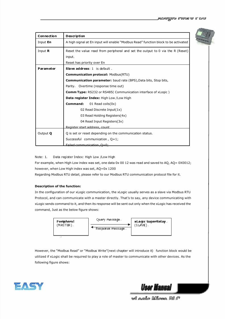
8/20/2019 XLogic User's Manual2
http://slidepdf.com/reader/full/xlogic-users-manual2 182/338
182
Connection Description
Input En A high signal at En input will enable “Modbus Read” function block to be activated
Input R Reset the value read from peripheral and set the output to 0 via the R (Reset)
input.
Reset has priority over En
Parameter Slave address: 1 is default .
Communication protocol: Modbus(RTU)
Communication parameter: baud rate (BPS),Data bits, Stop bits,
Parity, Overtime (response time out)
Comm Type: RS232 or RS485( Communication interface of xLogic )
Data register Index: High Low /Low High
Command: 01 Read coils(0x)
02 Read Discrete Input(1x)
03 Read Holding Registers(4x)
04 Read Input Registers(3x)
Register start address, count
Output Q Q is set or reset depending on the communication status.
Successful communication , Q=1;
Failed communication ,Q=0;
Note: 1. Data register Index: High Low /Low High
For example, when High Low index was set, one data 0x 00 12 was read and saved to AQ, AQ= 0X0012;
however, when Low High index was set, AQ=0x 1200
Regarding Modbus RTU detail, please refer to our Modbus RTU communication protocol file for it.
Description of the function:
In the configuration of our xLogic communication, the xLogic usually serves as a slave via Modbus RTU
Protocol, and can communicate with a master directly. That’s to say, any device communicating with
xLogic sends command to it, and then its response will be sent out only when the xLogic has received the
command, Just as the below figure shows:
However, the “Modbus Read” or “Modbus Write”(next chapter will introduce it) function block would be
utilized if xLogic shall be required to play a role of master to communicate with other devices. As the
following figure shows:
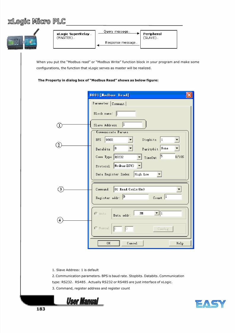
8/20/2019 XLogic User's Manual2
http://slidepdf.com/reader/full/xlogic-users-manual2 183/338
183
When you put the “Modbus read” or “Modbus Write” function block in your program and make some
configurations, the function that xLogic serves as master will be realized.
The Property in dialog box of “Modbus Read” shows as below figure:
1. Slave Address: 1 is default
2. Communication parameters:BPS is baud rate、Stopbits、Databits、Communication
type: RS232、RS485 . Actually RS232 or RS485 are just interface of xLogic.
3. Command, register address and register count
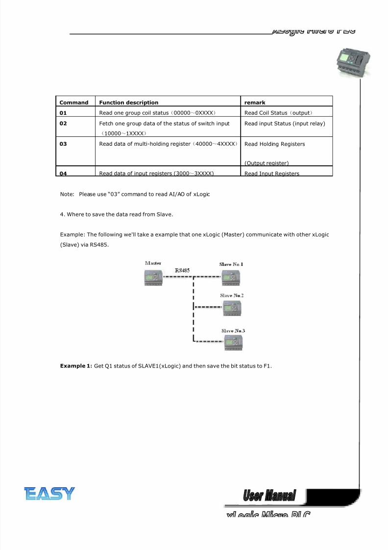
8/20/2019 XLogic User's Manual2
http://slidepdf.com/reader/full/xlogic-users-manual2 184/338
184
Command Function description remark
01 Read one group coil status(00000~0XXXX) Read Coil Status(output)
02 Fetch one group data of the status of switch input
(10000~1XXXX)
Read input Status (input relay)
03 Read data of multi-holding register(40000~4XXXX) Read Holding Registers
(Output register)
04 Read data of input registers (3000~3XXXX) Read Input Registers
Note: Please use “03” command to read AI/AO of xLogic
4. Where to save the data read from Slave.
Example: The following we'll take a example that one xLogic (Master) communicate with other xLogic
(Slave) via RS485.
Example 1: Get Q1 status of SLAVE1(xLogic) and then save the bit status to F1.
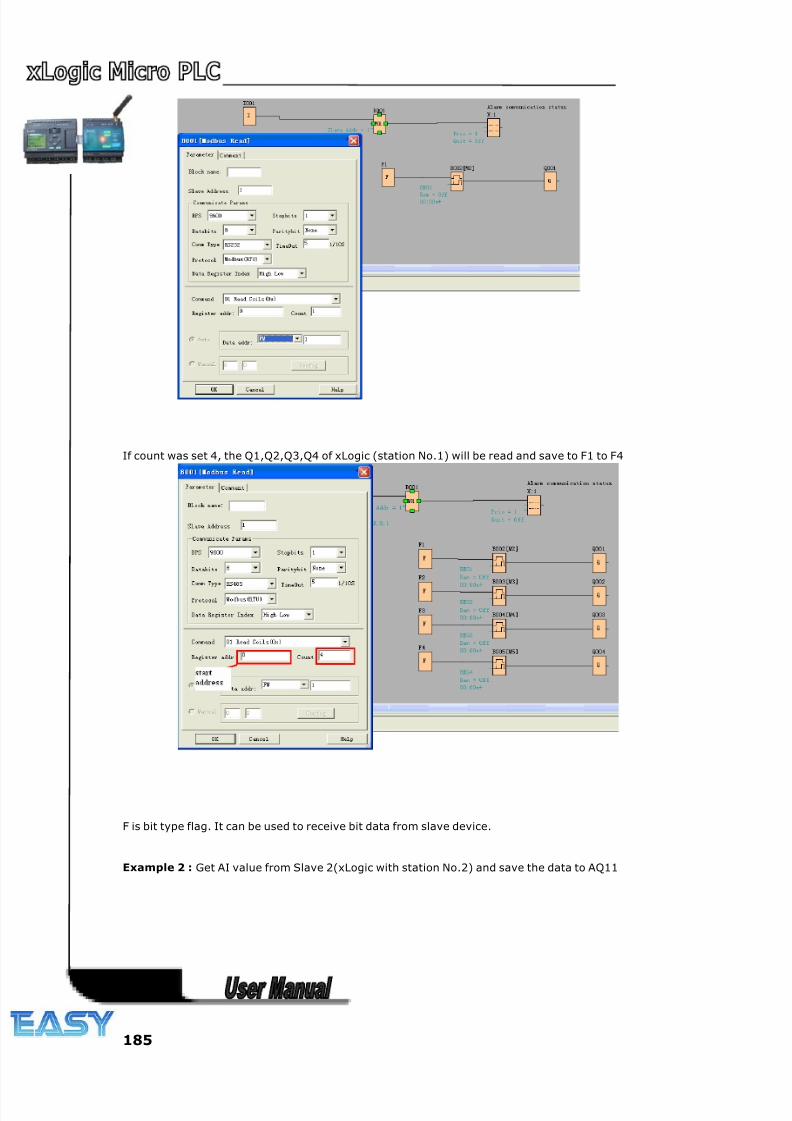
8/20/2019 XLogic User's Manual2
http://slidepdf.com/reader/full/xlogic-users-manual2 185/338
185
If count was set 4, the Q1,Q2,Q3,Q4 of xLogic (station No.1) will be read and save to F1 to F4
F is bit type flag. It can be used to receive bit data from slave device.
Example 2 : Get AI value from Slave 2(xLogic with station No.2) and save the data to AQ11
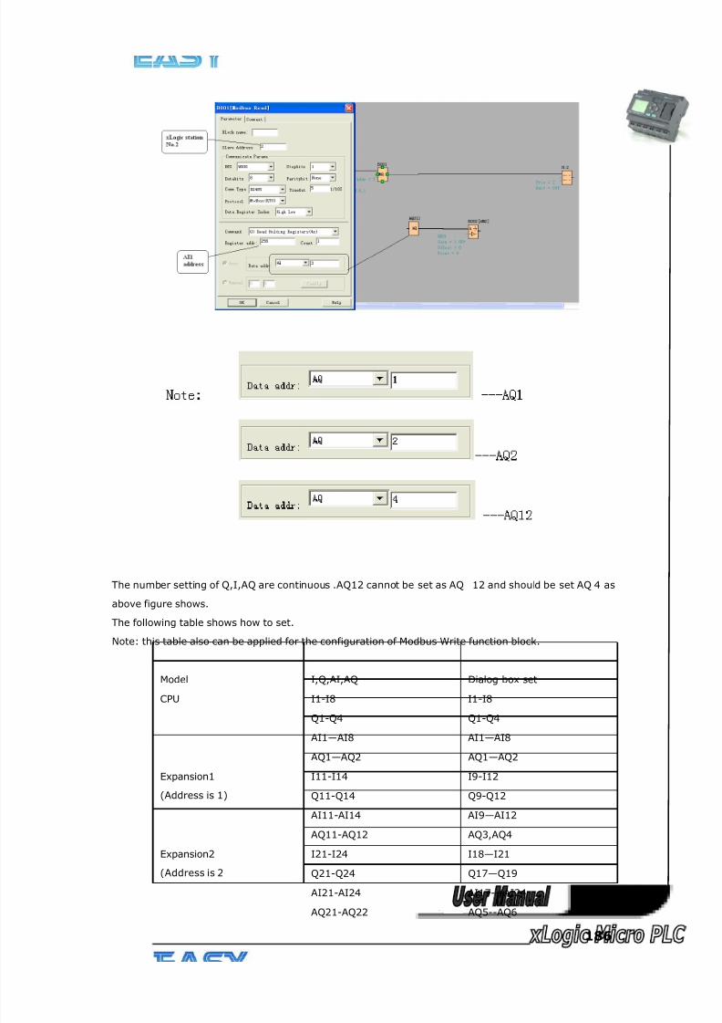
8/20/2019 XLogic User's Manual2
http://slidepdf.com/reader/full/xlogic-users-manual2 186/338
186
The number setting of Q,I,AQ are continuous .AQ12 cannot be set as AQ 12 and should be set AQ 4 as
above figure shows.
The following table shows how to set.
Note: this table also can be applied for the configuration of Modbus Write function block.
Model I,Q,AI,AQ Dialog box set
CPU I1-I8 I1-I8
Q1-Q4 Q1-Q4
AI1—AI8 AI1—AI8
AQ1—AQ2 AQ1—AQ2
Expansion1
(Address is 1)
I11-I14 I9-I12
Q11-Q14 Q9-Q12
AI11-AI14 AI9—AI12
AQ11-AQ12 AQ3,AQ4
Expansion2
(Address is 2
I21-I24 I18—I21
Q21-Q24 Q17—Q19
AI21-AI24 AI17---AI24
AQ21-AQ22 AQ5--AQ6
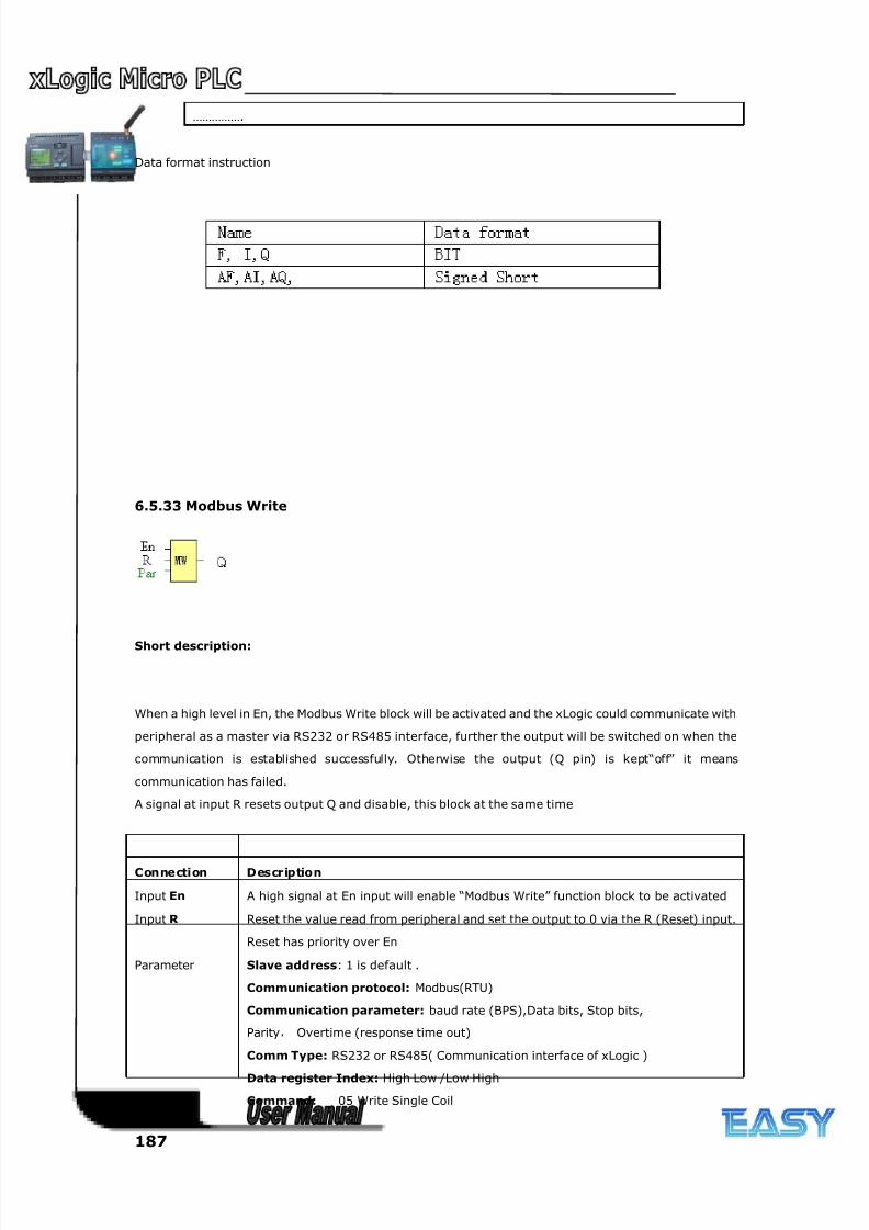
8/20/2019 XLogic User's Manual2
http://slidepdf.com/reader/full/xlogic-users-manual2 187/338
187
…………….
Data format instruction
6.5.33 Modbus Write
Short description:
When a high level in En, the Modbus Write block will be activated and the xLogic could communicate with
peripheral as a master via RS232 or RS485 interface, further the output will be switched on when the
communication is established successfully. Otherwise the output (Q pin) is kept“off” it means
communication has failed.
A signal at input R resets output Q and disable, this block at the same time
Connection Description
Input En A high signal at En input will enable “Modbus Write” function block to be activated
Input R Reset the value read from peripheral and set the output to 0 via the R (Reset) input.
Reset has priority over En
Parameter Slave address: 1 is default .
Communication protocol: Modbus(RTU)
Communication parameter: baud rate (BPS),Data bits, Stop bits,
Parity, Overtime (response time out)
Comm Type: RS232 or RS485( Communication interface of xLogic )
Data register Index: High Low /Low High
Command: 05 Write Single Coil
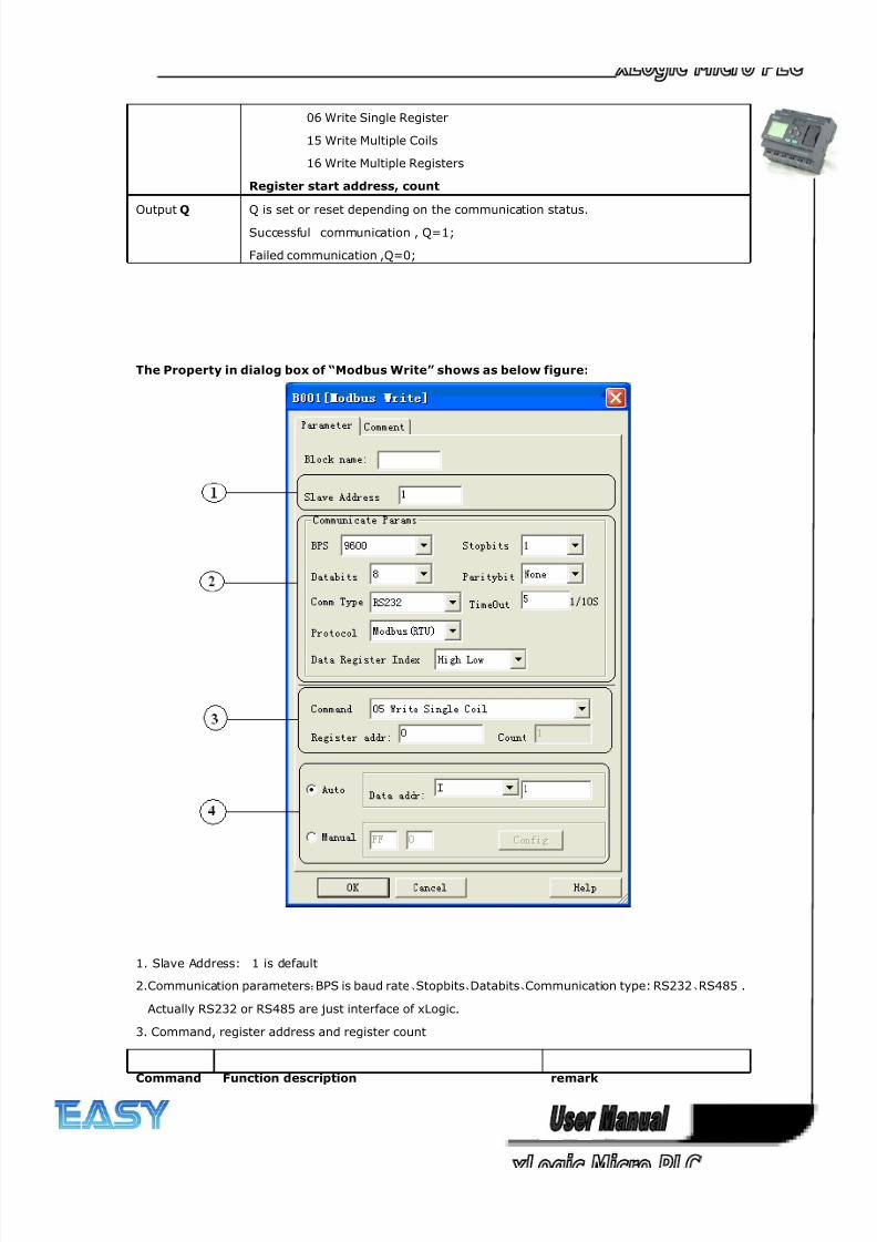
8/20/2019 XLogic User's Manual2
http://slidepdf.com/reader/full/xlogic-users-manual2 188/338
188
06 Write Single Register
15 Write Multiple Coils
16 Write Multiple Registers
Register start address, count
Output Q Q is set or reset depending on the communication status.
Successful communication , Q=1;
Failed communication ,Q=0;
The Property in dialog box of “Modbus Write” shows as below figure:
1. Slave Address: 1 is default
2.Communication parameters:BPS is baud rate、Stopbits、Databits、Communication type: RS232、RS485 .
Actually RS232 or RS485 are just interface of xLogic.
3. Command, register address and register count
Command Function description remark
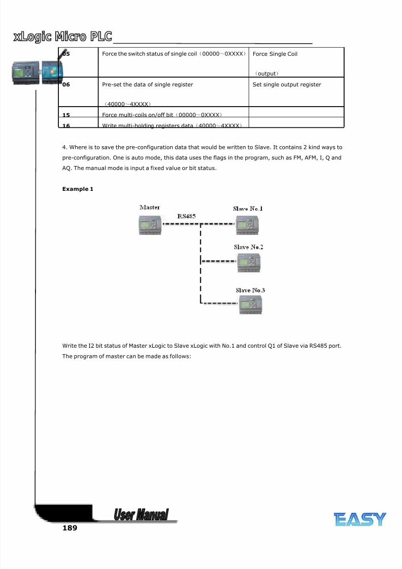
8/20/2019 XLogic User's Manual2
http://slidepdf.com/reader/full/xlogic-users-manual2 189/338
189
05 Force the switch status of single coil(00000~0XXXX) Force Single Coil
(output)
06 Pre-set the data of single register
(40000~4XXXX)
Set single output register
15 Force multi-coils on/off bit(00000~0XXXX)
16 Write multi-holding registers data(40000~4XXXX)
4. Where is to save the pre-configuration data that would be written to Slave. It contains 2 kind ways to
pre-configuration. One is auto mode, this data uses the flags in the program, such as FM, AFM, I, Q and
AQ. The manual mode is input a fixed value or bit status.
Example 1
Write the I2 bit status of Master xLogic to Slave xLogic with No.1 and control Q1 of Slave via RS485 port.
The program of master can be made as follows:
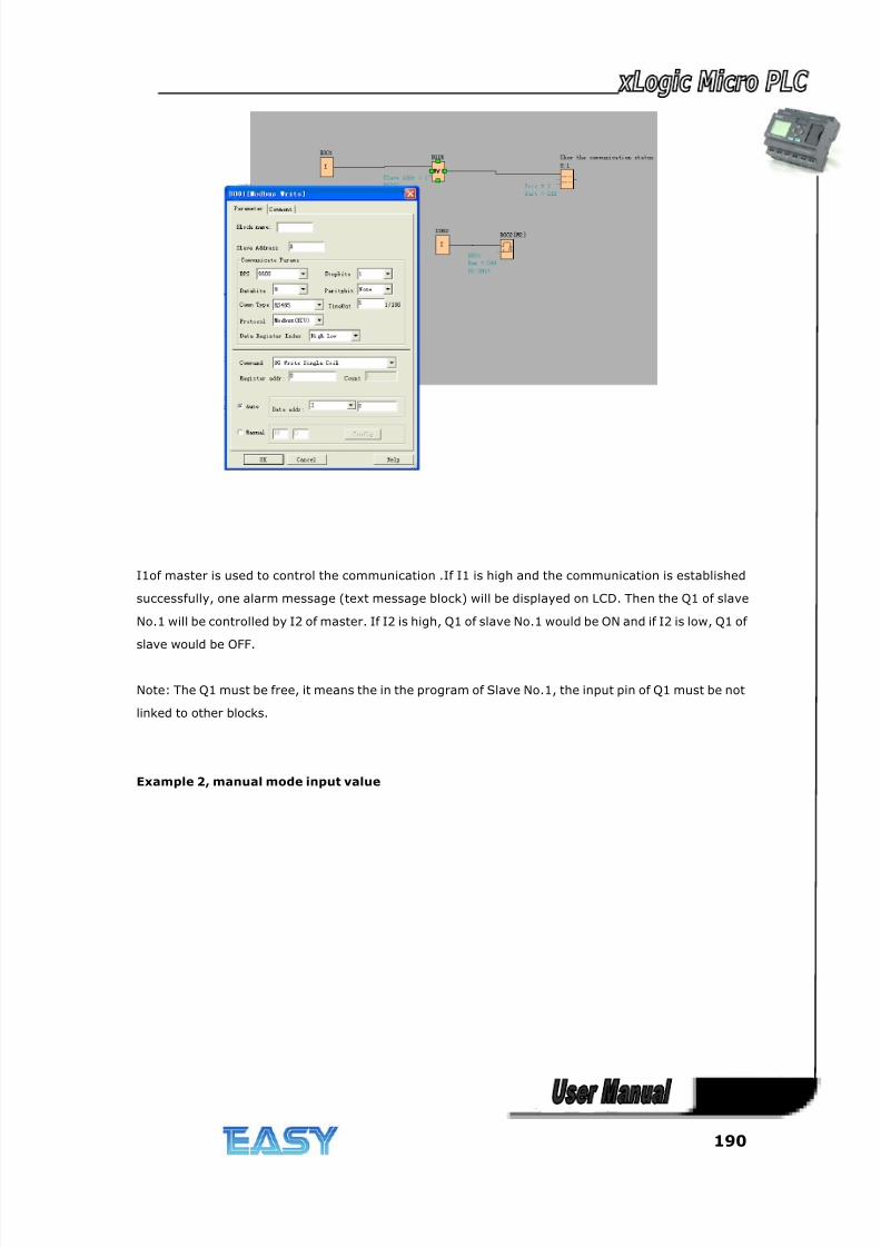
8/20/2019 XLogic User's Manual2
http://slidepdf.com/reader/full/xlogic-users-manual2 190/338
190
I1of master is used to control the communication .If I1 is high and the communication is established
successfully, one alarm message (text message block) will be displayed on LCD. Then the Q1 of slave
No.1 will be controlled by I2 of master. If I2 is high, Q1 of slave No.1 would be ON and if I2 is low, Q1 of
slave would be OFF.
Note: The Q1 must be free, it means the in the program of Slave No.1, the input pin of Q1 must be not
linked to other blocks.
Example 2, manual mode input value
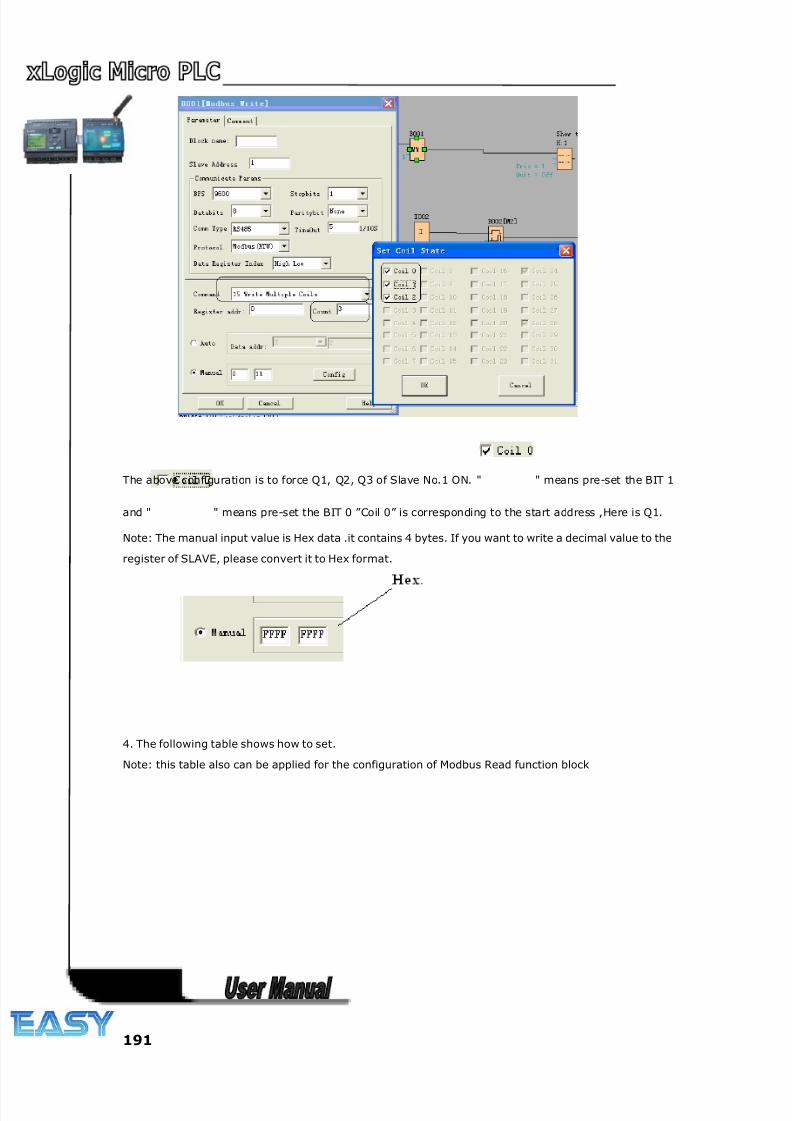
8/20/2019 XLogic User's Manual2
http://slidepdf.com/reader/full/xlogic-users-manual2 191/338
191
The above configuration is to force Q1, Q2, Q3 of Slave No.1 ON. " " means pre-set the BIT 1
and " " means pre-set the BIT 0 ”Coil 0” is corresponding to the start address ,Here is Q1.
Note: The manual input value is Hex data .it contains 4 bytes. If you want to write a decimal value to the
register of SLAVE, please convert it to Hex format.
4. The following table shows how to set.
Note: this table also can be applied for the configuration of Modbus Read function block
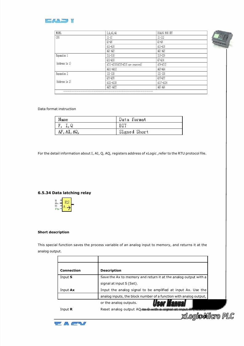
8/20/2019 XLogic User's Manual2
http://slidepdf.com/reader/full/xlogic-users-manual2 192/338
192
Data format instruction
For the detail information about I, AI, Q, AQ, registers address of xLogic ,refer to the RTU protocol file.
6.5.34 Data latching relay
Short description
This special function saves the process variable of an analog input to memory, and returns it at the
analog output.
Connection Description
Input S Save the Ax to memory and return it at the analog output with a
signal at input S (Set).
Input Ax Input the analog signal to be amplified at input Ax. Use the
analog inputs, the block number of a function with analog output,
or the analog outputs.
Input R Reset analog output AQ to 0 with a signal at input R (Reset).
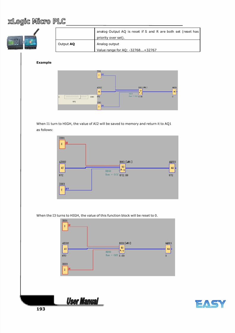
8/20/2019 XLogic User's Manual2
http://slidepdf.com/reader/full/xlogic-users-manual2 193/338
193
analog Output AQ is reset if S and R are both set (reset has
priority over set).
Output AQ Analog output
Value range for AQ: -32768...+32767
Example
When I1 turn to HIGH, the value of AI2 will be saved to memory and return it to AQ1
as follows:
When the I3 turns to HIGH, the value of this function block will be reset to 0.
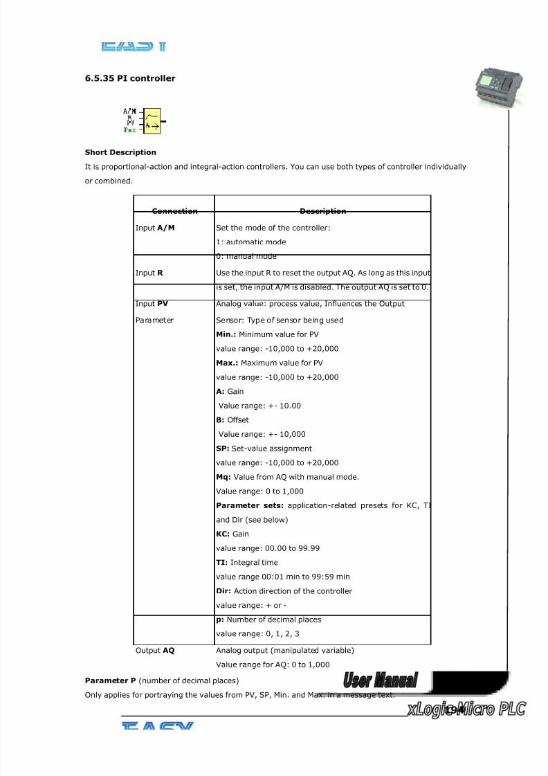
8/20/2019 XLogic User's Manual2
http://slidepdf.com/reader/full/xlogic-users-manual2 194/338
194
6.5.35 PI controller
Short Description
It is proportional-action and integral-action controllers. You can use both types of controller individually
or combined.
Connection Description
Input A/M Set the mode of the controller:
1: automatic mode
0: manual mode
Input R Use the input R to reset the output AQ. As long as this input
is set, the input A/M is disabled. The output AQ is set to 0.
Input PV Analog value: process value, Influences the Output
Parameter Sensor: Type of sensor being used
Min.: Minimum value for PV
value range: -10,000 to +20,000
Max.: Maximum value for PV
value range: -10,000 to +20,000
A: Gain
Value range: +- 10.00
B: Offset
Value range: +- 10,000
SP: Set-value assignment
value range: -10,000 to +20,000
Mq: Value from AQ with manual mode.
Value range: 0 to 1,000
Parameter sets: application-related presets for KC, TI
and Dir (see below)
KC: Gain
value range: 00.00 to 99.99
TI: Integral time
value range 00:01 min to 99:59 min
Dir: Action direction of the controller
value range: + or -
p: Number of decimal places
value range: 0, 1, 2, 3
Output AQ Analog output (manipulated variable)
Value range for AQ: 0 to 1,000
Parameter P (number of decimal places)
Only applies for portraying the values from PV, SP, Min. and Max. in a message text.
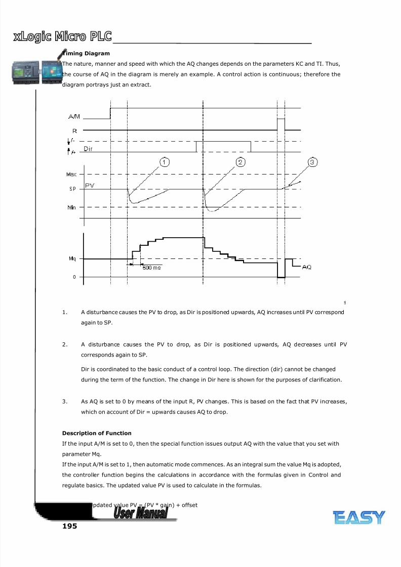
8/20/2019 XLogic User's Manual2
http://slidepdf.com/reader/full/xlogic-users-manual2 195/338
195
Timing Diagram
The nature, manner and speed with which the AQ changes depends on the parameters KC and TI. Thus,
the course of AQ in the diagram is merely an example. A control action is continuous; therefore the
diagram portrays just an extract.
1. A disturbance causes the PV to drop, as Dir is positioned upwards, AQ increases until PV correspond
again to SP.
2. A disturbance causes the PV to drop, as Dir is positioned upwards, AQ decreases until PV
corresponds again to SP.
Dir is coordinated to the basic conduct of a control loop. The direction (dir) cannot be changed
during the term of the function. The change in Dir here is shown for the purposes of clarification.
3. As AQ is set to 0 by means of the input R, PV changes. This is based on the fact that PV increases,
which on account of Dir = upwards causes AQ to drop.
Description of Function
If the input A/M is set to 0, then the special function issues output AQ with the value that you set with
parameter Mq.
If the input A/M is set to 1, then automatic mode commences. As an integral sum the value Mq is adopted,
the controller function begins the calculations in accordance with the formulas given in Control and
regulate basics. The updated value PV is used to calculate in the formulas.
Updated value PV = (PV * gain) + offset
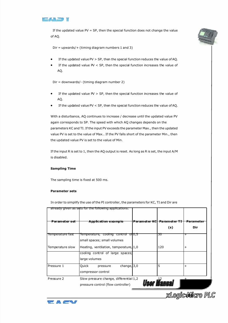
8/20/2019 XLogic User's Manual2
http://slidepdf.com/reader/full/xlogic-users-manual2 196/338
196
If the updated value PV = SP, then the special function does not change the value
of AQ.
Dir = upwards/+ (timing diagram numbers 1 and 3)
• If the updated value PV > SP, then the special function reduces the value of AQ.
• If the updated value PV < SP, then the special function increases the value of
AQ.
Dir = downwards/- (timing diagram number 2)
• If the updated value PV > SP, then the special function increases the value of
AQ.
• If the updated value PV < SP, then the special function reduces the value of AQ.
With a disturbance, AQ continues to increase / decrease until the updated value PV
again corresponds to SP. The speed with which AQ changes depends on the
parameters KC and TI. If the input PV exceeds the parameter Max., then the updated
value PV is set to the value of Max.. If the PV falls short of the parameter Min., then
the updated value PV is set to the value of Min.
If the input R is set to 1, then the AQ output is reset. As long as R is set, the input A/M
is disabled.
Sampling Time
The sampling time is fixed at 500 ms.
Parameter sets
In order to simplify the use of the PI controller, the parameters for KC, TI and Dir are
already given as sets for the following applications:
Parameter set Application example Parameter KC Parameter TI
(s)
Parameter
Dir
Temperature fast Temperature, cooling control of
small spaces; small volumes
0,5 30 +
Temperature slow Heating, ventilation, temperature,
cooling control of large spaces;
large volumes
1,0 120 +
Pressure 1 Quick pressure change,
compressor control
3,0 5 +
Pressure 2 Slow pressure change, differential
pressure control (flow controller)
1,2 12 +
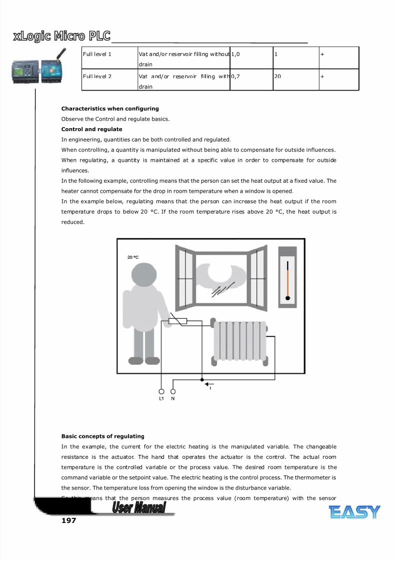
8/20/2019 XLogic User's Manual2
http://slidepdf.com/reader/full/xlogic-users-manual2 197/338
197
Full level 1 Vat and/or reservoir filling without
drain
1,0 1 +
Full level 2 Vat and/or reservoir fill ing with
drain
0,7 20 +
Characteristics when configuring
Observe the Control and regulate basics.
Control and regulate
In engineering, quantities can be both controlled and regulated.
When controlling, a quantity is manipulated without being able to compensate for outside influences.
When regulating, a quantity is maintained at a specific value in order to compensate for outside
influences.
In the following example, controlling means that the person can set the heat output at a fixed value. The
heater cannot compensate for the drop in room temperature when a window is opened.
In the example below, regulating means that the person can increase the heat output if the room
temperature drops to below 20 °C. If the room temperature rises above 20 °C, the heat output is
reduced.
Basic concepts of regulating
In the example, the current for the electric heating is the manipulated variable. The changeable
resistance is the actuator. The hand that operates the actuator is the control. The actual room
temperature is the controlled variable or the process value. The desired room temperature is the
command variable or the setpoint value. The electric heating is the control process. The thermometer is
the sensor. The temperature loss from opening the window is the disturbance variable.So this means that the person measures the process value (room temperature) with the sensor
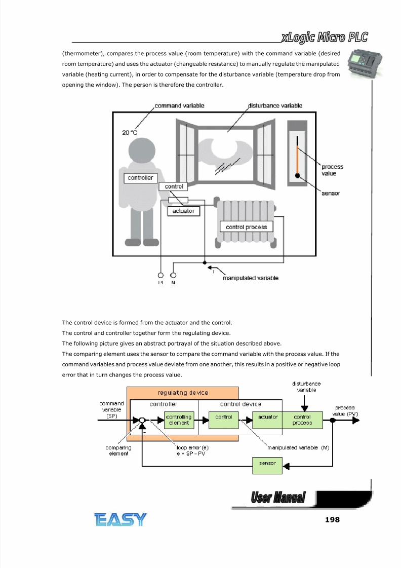
8/20/2019 XLogic User's Manual2
http://slidepdf.com/reader/full/xlogic-users-manual2 198/338
198
(thermometer), compares the process value (room temperature) with the command variable (desired
room temperature) and uses the actuator (changeable resistance) to manually regulate the manipulated
variable (heating current), in order to compensate for the disturbance variable (temperature drop from
opening the window). The person is therefore the controller.
The control device is formed from the actuator and the control.
The control and controller together form the regulating device.
The following picture gives an abstract portrayal of the situation described above.
The comparing element uses the sensor to compare the command variable with the process value. If the
command variables and process value deviate from one another, this results in a positive or negative loop
error that in turn changes the process value.
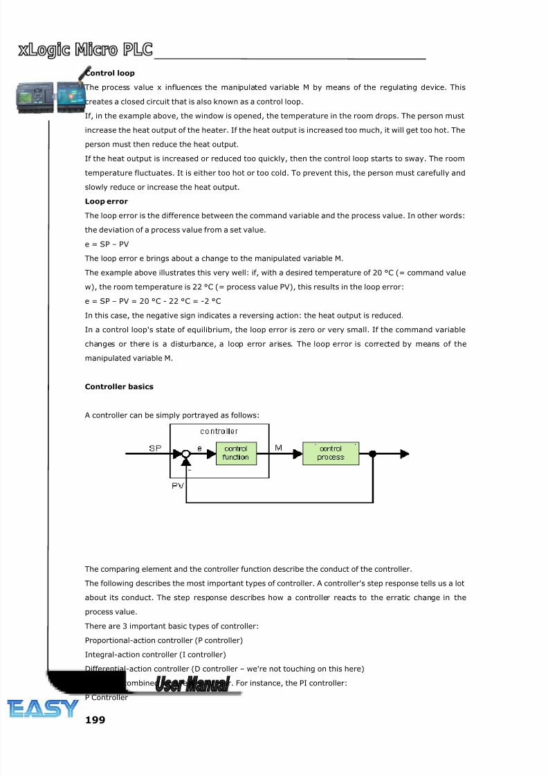
8/20/2019 XLogic User's Manual2
http://slidepdf.com/reader/full/xlogic-users-manual2 199/338
199
Control loop
The process value x influences the manipulated variable M by means of the regulating device. This
creates a closed circuit that is also known as a control loop.
If, in the example above, the window is opened, the temperature in the room drops. The person must
increase the heat output of the heater. If the heat output is increased too much, it will get too hot. The
person must then reduce the heat output.
If the heat output is increased or reduced too quickly, then the control loop starts to sway. The room
temperature fluctuates. It is either too hot or too cold. To prevent this, the person must carefully and
slowly reduce or increase the heat output.
Loop error
The loop error is the difference between the command variable and the process value. In other words:
the deviation of a process value from a set value.
e = SP – PV
The loop error e brings about a change to the manipulated variable M.
The example above illustrates this very well: if, with a desired temperature of 20 °C (= command value
w), the room temperature is 22 °C (= process value PV), this results in the loop error:
e = SP – PV = 20 °C - 22 °C = -2 °C
In this case, the negative sign indicates a reversing action: the heat output is reduced.
In a control loop's state of equilibrium, the loop error is zero or very small. If the command variable
changes or there is a disturbance, a loop error arises. The loop error is corrected by means of the
manipulated variable M.
Controller basics
A controller can be simply portrayed as follows:
The comparing element and the controller function describe the conduct of the controller.
The following describes the most important types of controller. A controller's step response tells us a lot
about its conduct. The step response describes how a controller reacts to the erratic change in the
process value.
There are 3 important basic types of controller:
Proportional-action controller (P controller)
Integral-action controller (I controller)
Differential-action controller (D controller – we're not touching on this here)
These are combined for a real controller. For instance, the PI controller:
P Controller
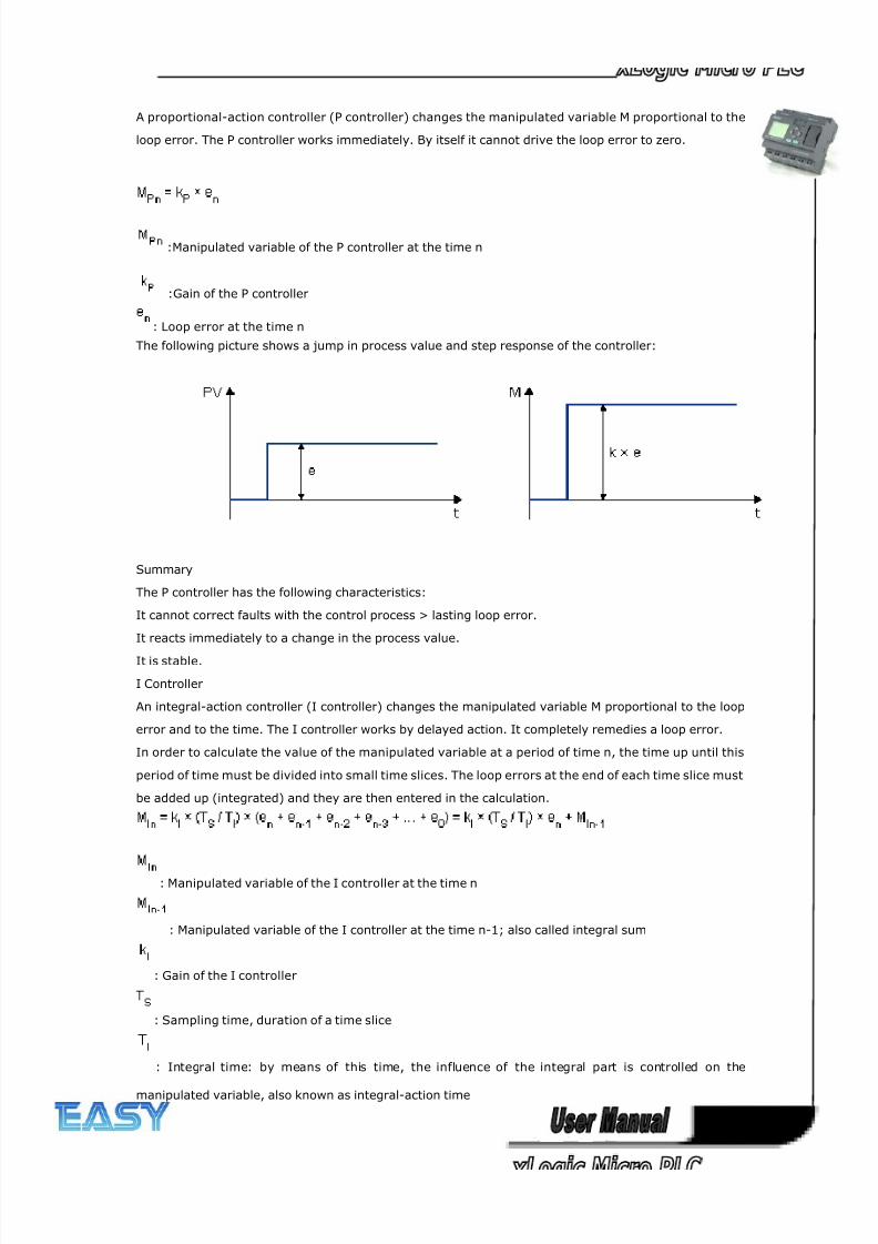
8/20/2019 XLogic User's Manual2
http://slidepdf.com/reader/full/xlogic-users-manual2 200/338
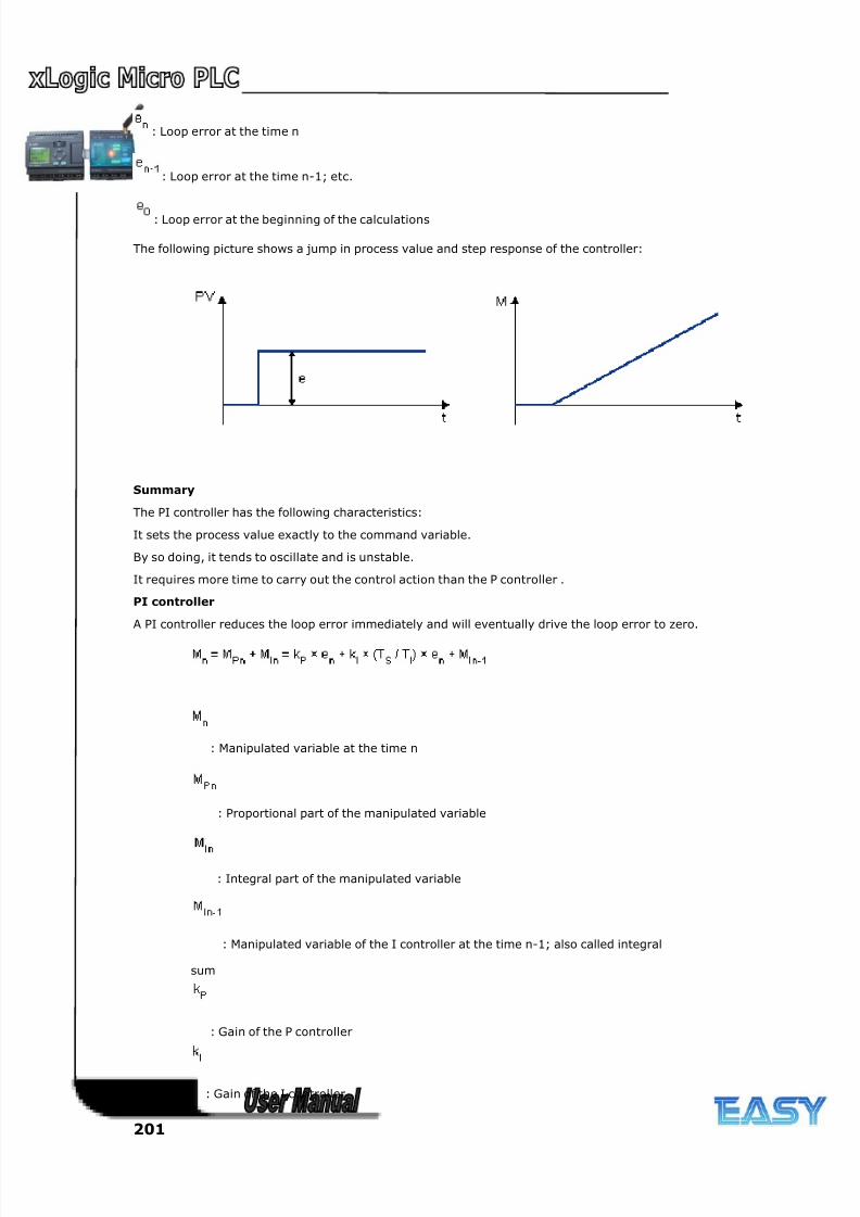
8/20/2019 XLogic User's Manual2
http://slidepdf.com/reader/full/xlogic-users-manual2 201/338
201
: Loop error at the time n
: Loop error at the time n-1; etc.
: Loop error at the beginning of the calculations
The following picture shows a jump in process value and step response of the controller:
Summary
The PI controller has the following characteristics:
It sets the process value exactly to the command variable.
By so doing, it tends to oscillate and is unstable.
It requires more time to carry out the control action than the P controller .
PI controller
A PI controller reduces the loop error immediately and will eventually drive the loop error to zero.
: Manipulated variable at the time n
: Proportional part of the manipulated variable
: Integral part of the manipulated variable
: Manipulated variable of the I controller at the time n-1; also called integral
sum
: Gain of the P controller
: Gain of the I controller
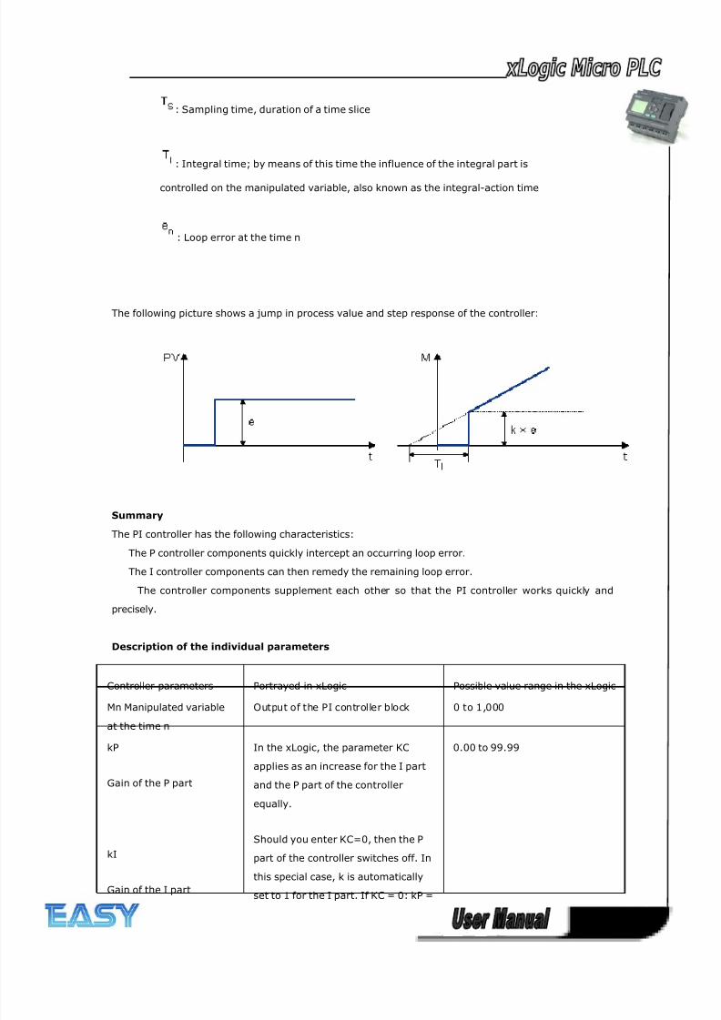
8/20/2019 XLogic User's Manual2
http://slidepdf.com/reader/full/xlogic-users-manual2 202/338
202
: Sampling time, duration of a time slice
: Integral time; by means of this time the influence of the integral part is
controlled on the manipulated variable, also known as the integral-action time
: Loop error at the time n
The following picture shows a jump in process value and step response of the controller:
Summary
The PI controller has the following characteristics:
The P controller components quickly intercept an occurring loop error.
The I controller components can then remedy the remaining loop error.
The controller components supplement each other so that the PI controller works quickly and
precisely.
Description of the individual parameters
Controller parameters Portrayed in xLogic Possible value range in the xLogic
Mn Manipulated variable
at the time n
Output of the PI controller block 0 to 1,000
kP
Gain of the P part
kI
Gain of the I part
In the xLogic, the parameter KC
applies as an increase for the I part
and the P part of the controller
equally.
Should you enter KC=0, then the P
part of the controller switches off. In
this special case, k is automatically
set to 1 for the I part. If KC = 0: kP =
0.00 to 99.99
8/20/2019 XLogic User's Manual2
http://slidepdf.com/reader/full/xlogic-users-manual2 203/338
203
0 and kI = 1
If KC <> 0: kP = kI = KC
Ts Sampling time,
duration of a time slice
Fixed 500 ms
TI Integral time Parameter TI, if you set this
parameter to 99:59 min, then you
switch off the I part of the controller.
00:01 min to 99.59 min
en
Loop error at the time n;
generally applies: e = SP –
PV
Refer to SP and PV "
SP The parameter SP is the set-value
assignment w. For this parameter you
can use the analog output of a
different special function.
-10,000 to +20,000
PV PV is the process value x and is
calculated as follows:
PV = (analog value on input * gain) +
offset.
You can connect the input for
example by means of an analog input
with a PT100 sensor.
"
The gain parameter has an effect on
PV
0.0 to 10.0
The offset parameter has an effect on
PV
-10,000 to +20,000
PV is restricted by the parameters
Min. and Max.
In each case: -10,000 to +20,000
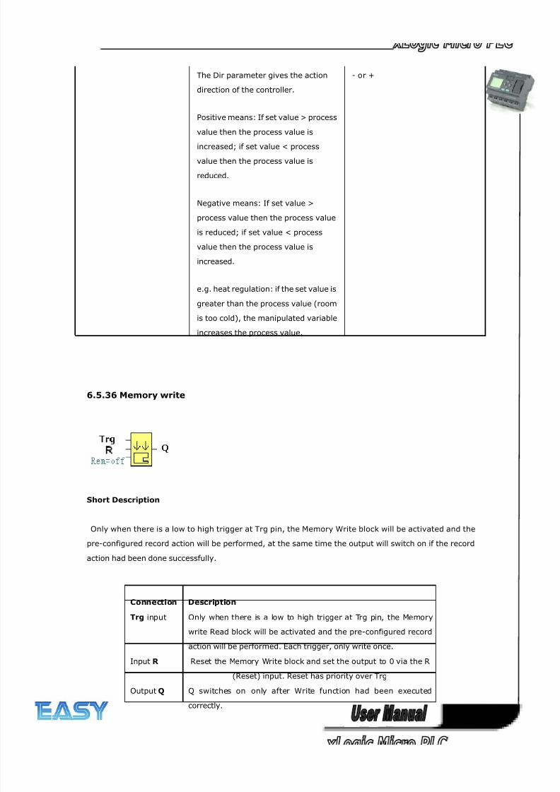
8/20/2019 XLogic User's Manual2
http://slidepdf.com/reader/full/xlogic-users-manual2 204/338
204
The Dir parameter gives the action
direction of the controller.
Positive means: If set value > process
value then the process value is
increased; if set value < process
value then the process value is
reduced.
Negative means: If set value >
process value then the process value
is reduced; if set value < process
value then the process value is
increased.
e.g. heat regulation: if the set value is
greater than the process value (room
is too cold), the manipulated variable
increases the process value.
- or +
6.5.36 Memory write
Short Description
Only when there is a low to high trigger at Trg pin, the Memory Write block will be activated and the
pre-configured record action will be performed, at the same time the output will switch on if the record
action had been done successfully.
Connection Description
Trg input Only when there is a low to high trigger at Trg pin, the Memory
write Read block will be activated and the pre-configured record
action will be performed. Each trigger, only write once.
Input R Reset the Memory Write block and set the output to 0 via the R
(Reset) input. Reset has priority over Trg
Output Q Q switches on only after Write function had been executedcorrectly.
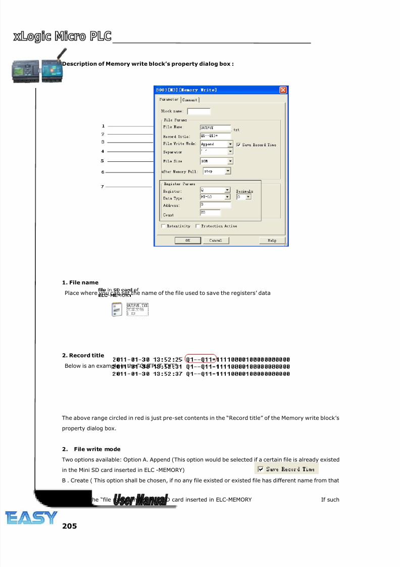
8/20/2019 XLogic User's Manual2
http://slidepdf.com/reader/full/xlogic-users-manual2 205/338
205
Description of Memory write block’s property dialog box :
1. File name
Place where you can set the name of the file used to save the registers’ data
2. Record title
Below is an example in the “OUTPUT.TXT”
The above range circled in red is just pre-set contents in the “Record title” of the Memory write block’s
property dialog box.
2. File write mode
Two options available: Option A. Append (This option would be selected if a certain file is already existed
in the Mini SD card inserted in ELC -MEMORY)
B . Create ( This option shall be chosen, if no any file existed or existed file has different name from that
pre-set in the “file name” in the Mini SD card inserted in ELC-MEMORY If such
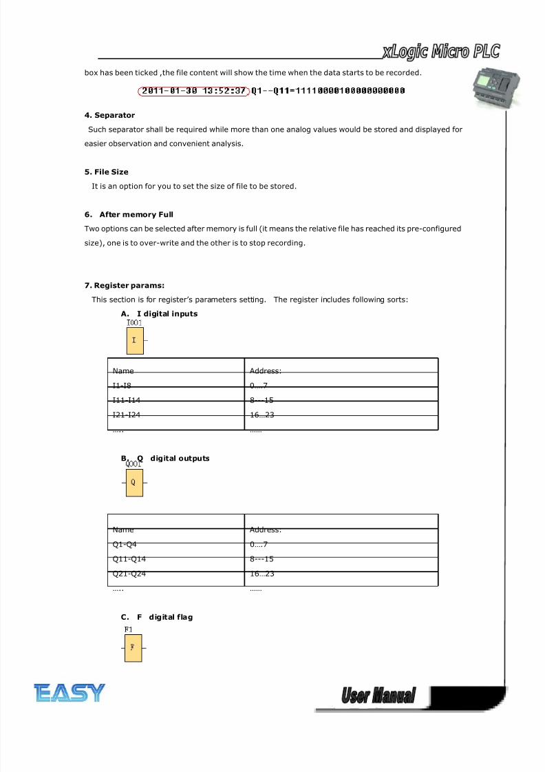
8/20/2019 XLogic User's Manual2
http://slidepdf.com/reader/full/xlogic-users-manual2 206/338
206
box has been ticked ,the file content will show the time when the data starts to be recorded.
4. Separator
Such separator shall be required while more than one analog values would be stored and displayed for
easier observation and convenient analysis.
5. File Size
It is an option for you to set the size of file to be stored.
6. After memory Full
Two options can be selected after memory is full (it means the relative file has reached its pre-configured
size), one is to over-write and the other is to stop recording.
7. Register params:
This section is for register’s parameters setting. The register includes following sorts:
A. I digital inputs
Name Address:
I1-I8 0….7
I11-I14 8---15
I21-I24 16…23
….. ……
B. Q digital outputs
Name Address:
Q1-Q4 0….7
Q11-Q14 8---15
Q21-Q24 16…23
….. ……
C. F digital flag
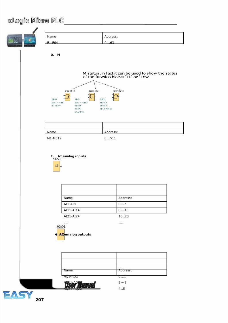
8/20/2019 XLogic User's Manual2
http://slidepdf.com/reader/full/xlogic-users-manual2 207/338
207
Name Address:
F1-F64 0….63
D. M
Name Address:
M1-M512 0….511
F. AI analog inputs
Name Address:
AI1-AI8 0….7
AI11-AI14 8---15
AI21-AI24 16…23
….. ……
G. AQ analog outputs
Name Address:
AQ1-AQ2 0….1
AQ11-AQ12 2---3
AQ21-AQ22 4…5
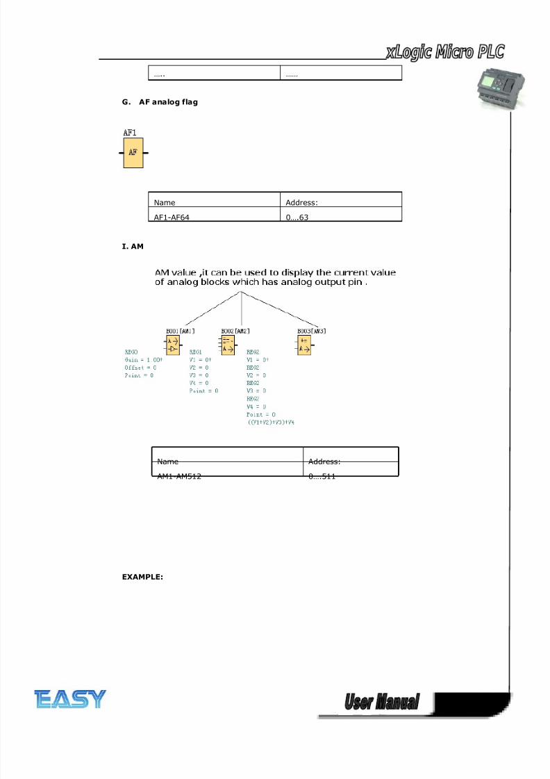
8/20/2019 XLogic User's Manual2
http://slidepdf.com/reader/full/xlogic-users-manual2 208/338
208
G. AF analog flag
Name Address:
AF1-AF64 0….63
I. AM
Name Address:
AM1-AM512 0….511
EXAMPLE:
….. ……
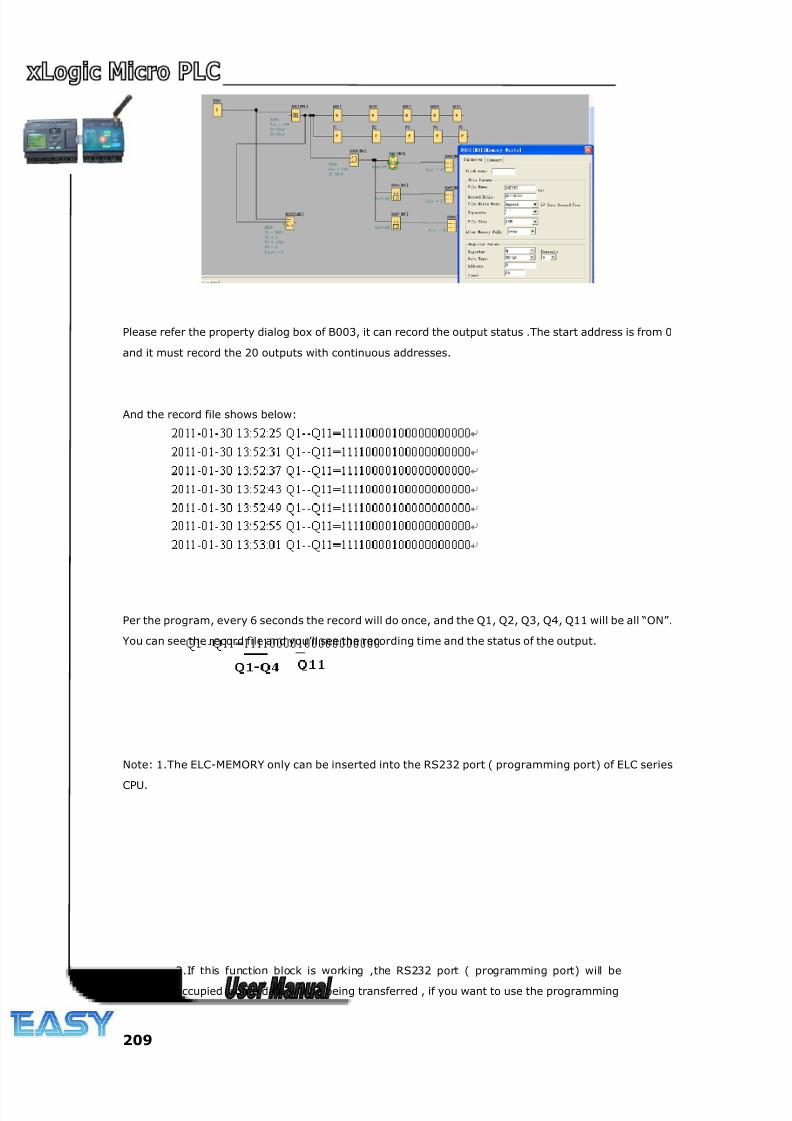
8/20/2019 XLogic User's Manual2
http://slidepdf.com/reader/full/xlogic-users-manual2 209/338
209
Please refer the property dialog box of B003, it can record the output status .The start address is from 0
and it must record the 20 outputs with continuous addresses.
And the record file shows below:
Per the program, every 6 seconds the record will do once, and the Q1, Q2, Q3, Q4, Q11 will be all “ON”.
You can see the record file and you’ll see the recording time and the status of the output.
Note: 1.The ELC-MEMORY only can be inserted into the RS232 port ( programming port) of ELC series
CPU.
2.If this function block is working ,the RS232 port ( programming port) will be
occupied ,some data will be being transferred , if you want to use the programming
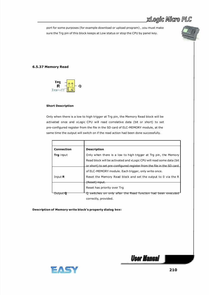
8/20/2019 XLogic User's Manual2
http://slidepdf.com/reader/full/xlogic-users-manual2 210/338
210
port for some purposes (for example download or upload program) , you must make
sure the Trg pin of this block keeps at Low status or stop the CPU by panel key.
6.5.37 Memory Read
Short Description
Only when there is a low to high trigger at Trg pin, the Memory Read block will be
activated once and xLogic CPU will read correlative data (bit or short) to set
pre-configured register from the file in the SD card of ELC-MEMORY module, at the
same time the output will switch on if the read action had been done successfully.
Connection Description
Trg input Only when there is a low to high trigger at Trg pin, the Memory
Read block will be activated and xLogic CPU will read some data (bit
or short) to set pre-configured register from the file in the SD card
of ELC-MEMORY module. Each trigger, only write once.
Input R Reset the Memory Read block and set the output to 0 via the R
(Reset) input.
Reset has priority over Trg
Output Q Q switches on only after the Read function had been executed
correctly, provided.
Description of Memory write block’s property dialog box:
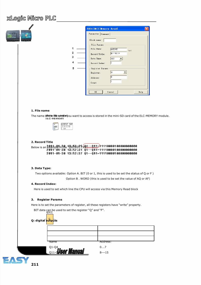
8/20/2019 XLogic User's Manual2
http://slidepdf.com/reader/full/xlogic-users-manual2 211/338
211
1. File name
The name of the file which you want to access is stored in the mini-SD card of the ELC-MEMORY module.
2. Record Title
Below is an example in the “OUTPUT.TXT”
3. Data Type:
Two options available: Option A. BIT (0 or 1, this is used to be set the status of Q or F )
Option B . WORD (this is used to be set the value of AQ or AF)
4. Record Index:
Here is used to set which line the CPU will access via this Memory Read block
3. Register Params
Here is to set the parameters of register, all these registers have “write” property.
BIT data can be used to set the register “Q” and “F”.
Q: digital outputs
Name Address:
Q1-Q4 0….7
Q11-Q14 8---15
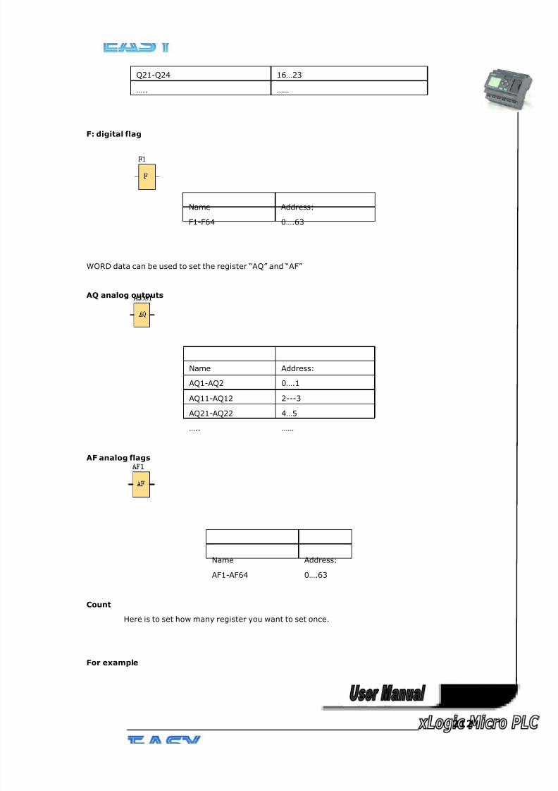
8/20/2019 XLogic User's Manual2
http://slidepdf.com/reader/full/xlogic-users-manual2 212/338
212
Q21-Q24 16…23
….. ……
F: digital flag
Name Address:
F1-F64 0….63
WORD data can be used to set the register “AQ” and “AF”
AQ analog outputs
Name Address:
AQ1-AQ2 0….1
AQ11-AQ12 2---3
AQ21-AQ22 4…5
….. ……
AF analog flags
Name Address:
AF1-AF64 0….63
Count
Here is to set how many register you want to set once.
For example
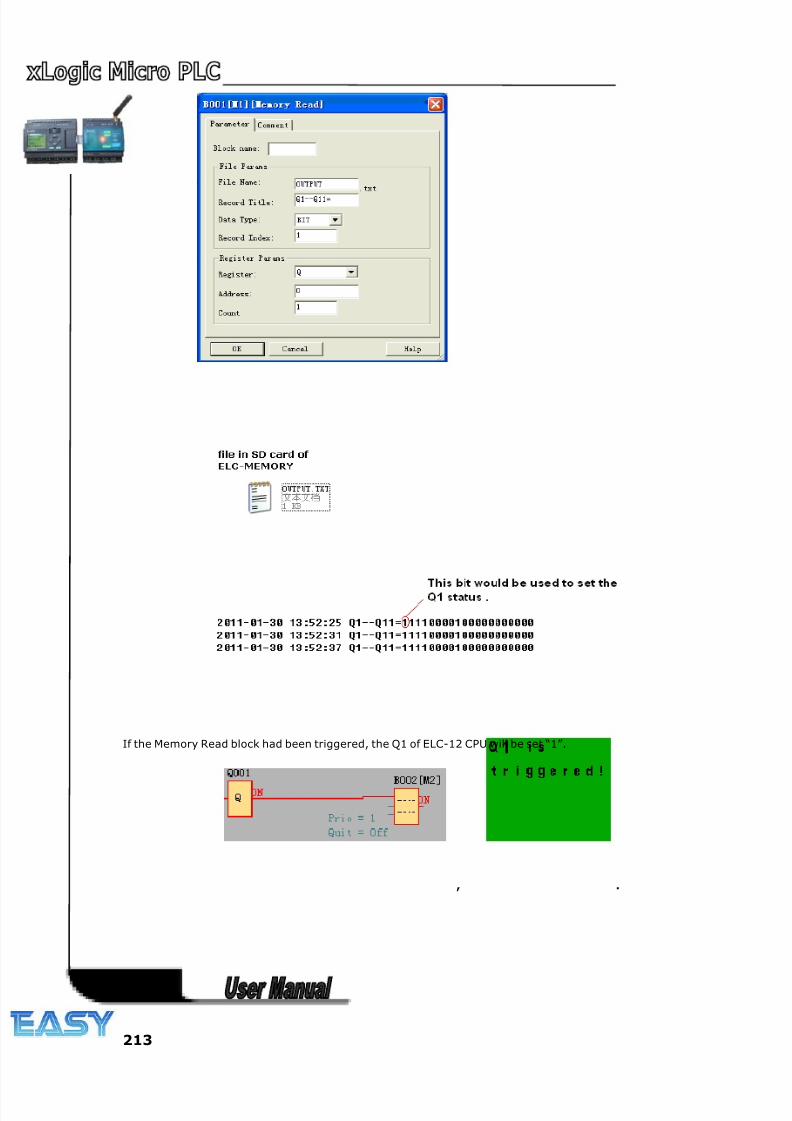
8/20/2019 XLogic User's Manual2
http://slidepdf.com/reader/full/xlogic-users-manual2 213/338
213
If the Memory Read block had been triggered, the Q1 of ELC-12 CPU will be set “1”.
, .
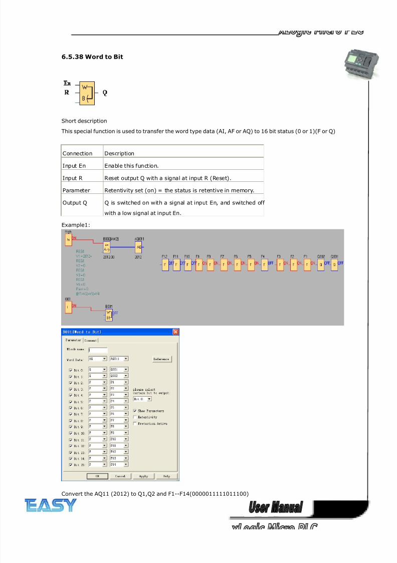
8/20/2019 XLogic User's Manual2
http://slidepdf.com/reader/full/xlogic-users-manual2 214/338
214
6.5.38 Word to Bit
Short description
This special function is used to transfer the word type data (AI, AF or AQ) to 16 bit status (0 or 1)(F or Q)
Connection Description
Input En Enable this function.
Input R Reset output Q with a signal at input R (Reset).
Parameter Retentivity set (on) = the status is retentive in memory.
Output Q Q is switched on with a signal at input En, and switched off
with a low signal at input En.
Example1:
Convert the AQ11 (2012) to Q1,Q2 and F1--F14(0000011111011100)
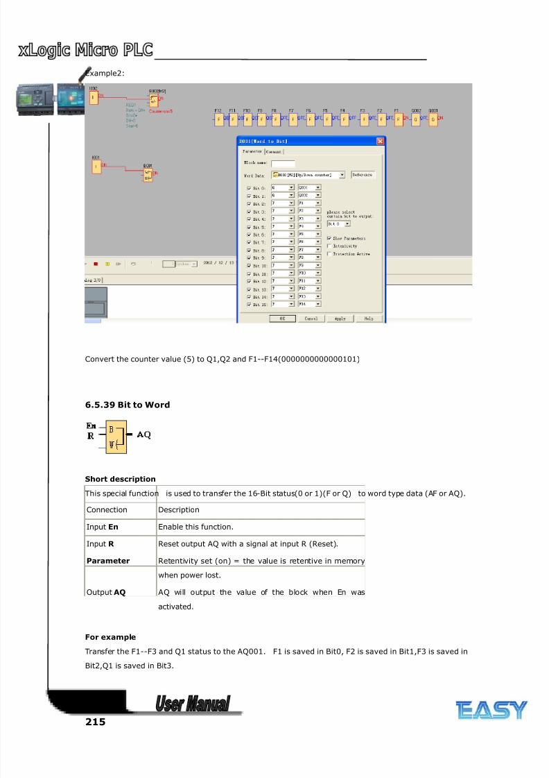
8/20/2019 XLogic User's Manual2
http://slidepdf.com/reader/full/xlogic-users-manual2 215/338
215
Example2:
Convert the counter value (5) to Q1,Q2 and F1--F14(0000000000000101)
6.5.39 Bit to Word
Short description
This special function is used to transfer the 16-Bit status(0 or 1)(F or Q) to word type data (AF or AQ).
Connection Description
Input En Enable this function.
Input R Reset output AQ with a signal at input R (Reset).
Parameter Retentivity set (on) = the value is retentive in memory
when power lost.
Output AQ AQ will output the value of the block when En was
activated.
For example
Transfer the F1--F3 and Q1 status to the AQ001. F1 is saved in Bit0, F2 is saved in Bit1,F3 is saved in
Bit2,Q1 is saved in Bit3.
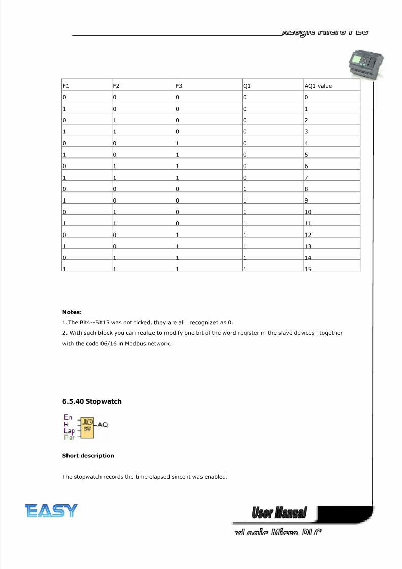
8/20/2019 XLogic User's Manual2
http://slidepdf.com/reader/full/xlogic-users-manual2 216/338
216
F1 F2 F3 Q1 AQ1 value
0 0 0 0 0
1 0 0 0 1
0 1 0 0 2
1 1 0 0 3
0 0 1 0 4
1 0 1 0 5
0 1 1 0 6
1 1 1 0 7
0 0 0 1 8
1 0 0 1 9
0 1 0 1 10
1 1 0 1 11
0 0 1 1 12
1 0 1 1 13
0 1 1 1 14
1 1 1 1 15
Notes:
1.The Bit4--Bit15 was not ticked, they are all recognized as 0.
2. With such block you can realize to modify one bit of the word register in the slave devices together
with the code 06/16 in Modbus network.
6.5.40 Stopwatch
Short description
The stopwatch records the time elapsed since it was enabled.
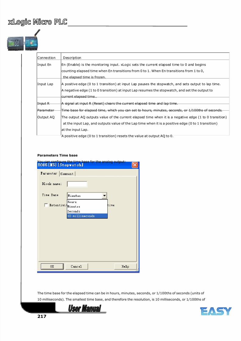
8/20/2019 XLogic User's Manual2
http://slidepdf.com/reader/full/xlogic-users-manual2 217/338
217
Connection Description
Input En En (Enable) is the monitoring input. xLogic sets the current elapsed time to 0 and begins
counting elapsed time when En transitions from 0 to 1. When En transitions from 1 to 0,
the elapsed time is frozen.
Input Lap A positive edge (0 to 1 transition) at input Lap pauses the stopwatch, and sets output to lap time.
A negative edge (1 to 0 transition) at input Lap resumes the stopwatch, and set the output to
current elapsed time..
Input R A signal at input R (Reset) clears the current elapsed time and lap time.
Parameter Time base for elapsed time, which you can set to hours, minutes, seconds, or 1/100ths of seconds.
Output AQ The output AQ outputs value of the current elapsed time when it is a negative edge (1 to 0 transition)
at the input Lap, and outputs value of the Lap time when it is a positive edge (0 to 1 transition)
at the input Lap.
A positive edge (0 to 1 transition) resets the value at output AQ to 0.
Parameters Time base
You can configure the time base for the analog output:
The time base for the elapsed time can be in hours, minutes, seconds, or 1/100ths of seconds (units of
10 milliseconds). The smallest time base, and therefore the resolution, is 10 milliseconds, or 1/100ths of
seconds.
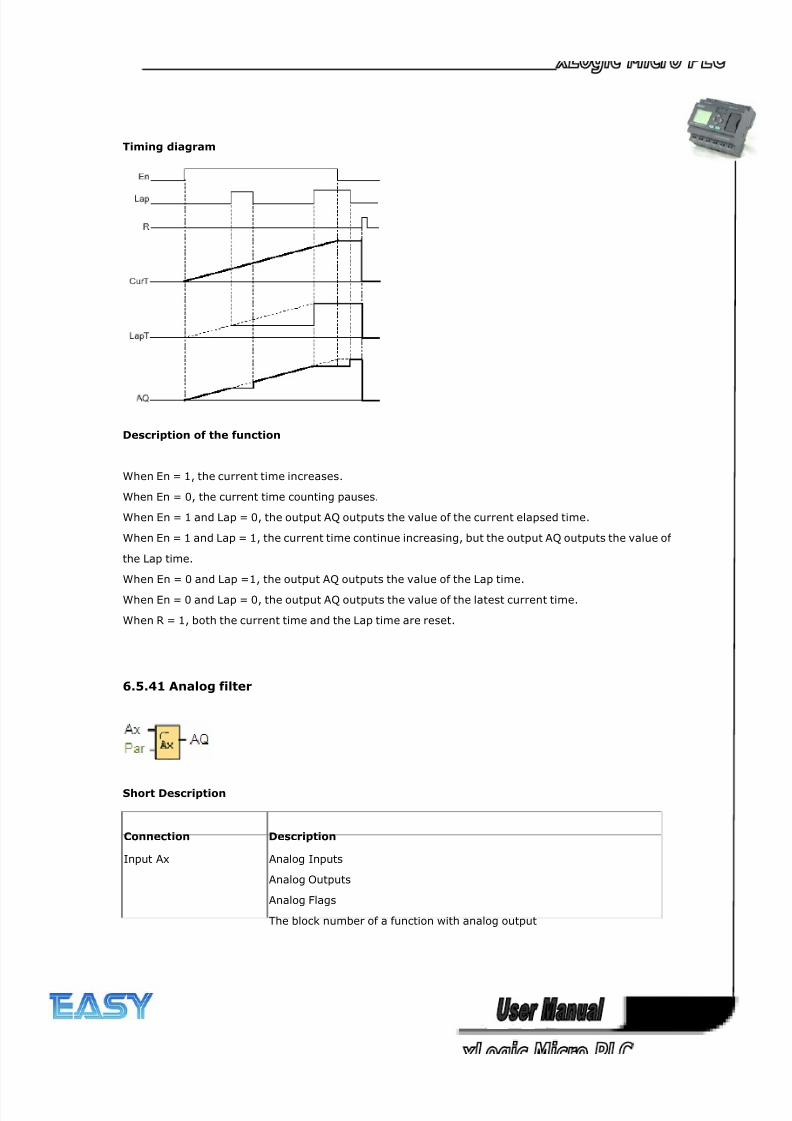
8/20/2019 XLogic User's Manual2
http://slidepdf.com/reader/full/xlogic-users-manual2 218/338
218
Timing diagram
Description of the function
When En = 1, the current time increases.
When En = 0, the current time counting pauses.
When En = 1 and Lap = 0, the output AQ outputs the value of the current elapsed time.
When En = 1 and Lap = 1, the current time continue increasing, but the output AQ outputs the value of
the Lap time.
When En = 0 and Lap =1, the output AQ outputs the value of the Lap time.
When En = 0 and Lap = 0, the output AQ outputs the value of the latest current time.
When R = 1, both the current time and the Lap time are reset.
6.5.41 Analog filter
Short Description
Connection Description
Input Ax Analog Inputs
Analog Outputs
Analog Flags
The block number of a function with analog output
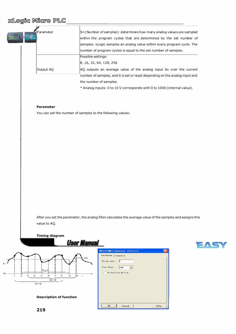
8/20/2019 XLogic User's Manual2
http://slidepdf.com/reader/full/xlogic-users-manual2 219/338
219
Parameter Sn (Number of samples): determines how many analog values are sampled
within the program cycles that are determined by the set number of
samples. xLogic samples an analog value within every program cycle. The
number of program cycles is equal to the set number of samples.
Possible settings:
8, 16, 32, 64, 128, 256
Output AQ AQ outputs an average value of the analog input Ax over the current
number of samples, and it is set or reset depending on the analog input and
the number of samples.
* Analog inputs: 0 to 10 V corresponds with 0 to 1000 (internal value).
Parameter
You can set the number of samples to the following values:
After you set the parameter, the analog filter calculates the average value of the samples and assigns this
value to AQ.
Timing diagram
Description of function

8/20/2019 XLogic User's Manual2
http://slidepdf.com/reader/full/xlogic-users-manual2 220/338
220
The function outputs the average value after sampling the analog input signal according to the set
number of samples. This SFB can reduce the error of analog input signal.
Note
There are a maximum of eight analog filter function blocks available for use in the circuit program in
xLogicsoft.
6.5.42 Max/Min
Connection Description
Input En The function of input En (Enable) depends on the settings of parameter Mode
and the selection of check box "when En = 0, reset Max/Min".
Input S1 This input is enabled when you set Mode =2:
A positive transition (0 to 1) at input S1 sets the output AQ to the maximum
value..
A negative transition (1 to 0) at input S1 sets the output AQ to the minimum
value.
Input Ax Input Ax is one of the following analog signals:
Analog Inputs
Analog Outputs
Analog flags
Block number of a function with analog output
Parameter
Mode
Possible settings: 0, 1, 2, 3
Mode = 0: AQ = Min
Mode = 1: AQ = Max
Mode = 2 and S1= 0 (low): AQ = Min
Mode = 2 and S1= 1 (high): AQ = Max
Mode = 3 or a block value is referenced: AQ = Ax
Output AQ AQ outputs a minimum, maximum, or actual value depending on the inputs, or
is reset to 0 if configured to do so when function is disabled
Analog inputs: 0 to 10 V corresponds with 0 to 1000 (internal value).
Parameter Mode
You can set the values for parameter Mode based on the actual values of another already-programmed
function:
Analog comparator: Ax - Ay
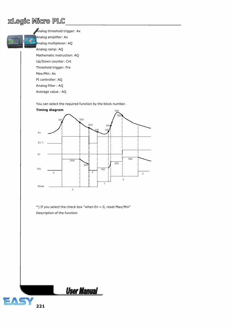
8/20/2019 XLogic User's Manual2
http://slidepdf.com/reader/full/xlogic-users-manual2 221/338
221
Analog threshold trigger: Ax
Analog amplifier: Ax
Analog multiplexer: AQ
Analog ramp: AQ
Mathematic instruction: AQ
Up/Down counter: Cnt
Threshold trigger: Fre
Max/Min: Ax
PI controller: AQ
Analog filter : AQ
Average value : AQ
You can select the required function by the block number.
Timing diagram
*) If you select the check box "when En = 0, reset Max/Min"
Description of the function
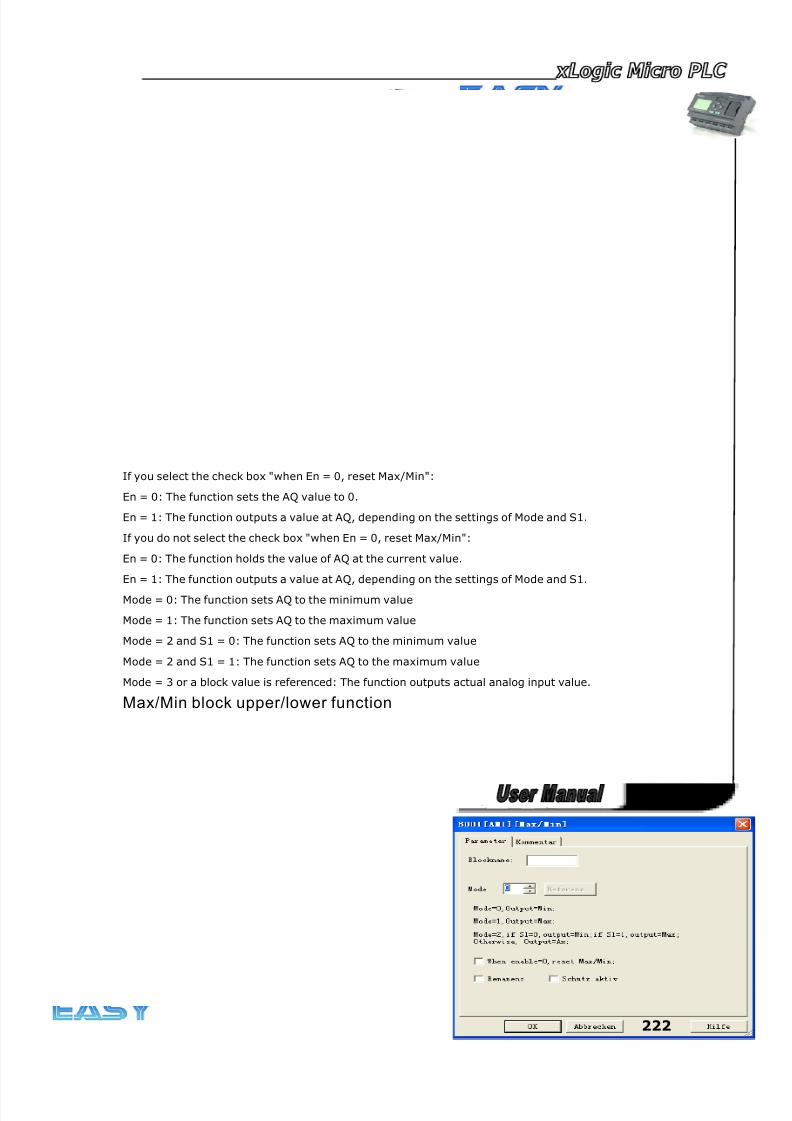
8/20/2019 XLogic User's Manual2
http://slidepdf.com/reader/full/xlogic-users-manual2 222/338
222
If you select the check box "when En = 0, reset Max/Min":
En = 0: The function sets the AQ value to 0.
En = 1: The function outputs a value at AQ, depending on the settings of Mode and S1.
If you do not select the check box "when En = 0, reset Max/Min":
En = 0: The function holds the value of AQ at the current value.
En = 1: The function outputs a value at AQ, depending on the settings of Mode and S1.
Mode = 0: The function sets AQ to the minimum value
Mode = 1: The function sets AQ to the maximum value
Mode = 2 and S1 = 0: The function sets AQ to the minimum value
Mode = 2 and S1 = 1: The function sets AQ to the maximum value
Mode = 3 or a block value is referenced: The function outputs actual analog input value.
Max/Min block upper/lower function
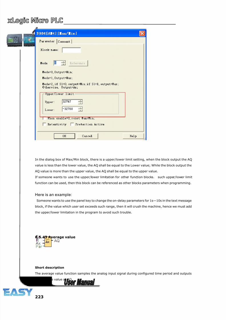
8/20/2019 XLogic User's Manual2
http://slidepdf.com/reader/full/xlogic-users-manual2 223/338
223
In the dialog box of Max/Min block, there is a upper/lower limit setting, when the block output the AQ
value is less than the lower value, the AQ shall be equal to the Lower value; While the block output the
AQ value is more than the upper value, the AQ shall be equal to the upper value.
If someone wants to use the upper/lower limitation for other function blocks. such upper/lower limit
function can be used, then this block can be referenced as other blocks parameters when programming.
Here is an example:
Someone wants to use the panel key to change the on-delay parameters for 1s—10s in the text message
block, if the value which user set exceeds such range, then it will crush the machine, hence we must add
the upper/lower limitation in the program to avoid such trouble.
6.5.43 Average value
Short description
The average value function samples the analog input signal during configured time period and outputs
the average value at AQ.
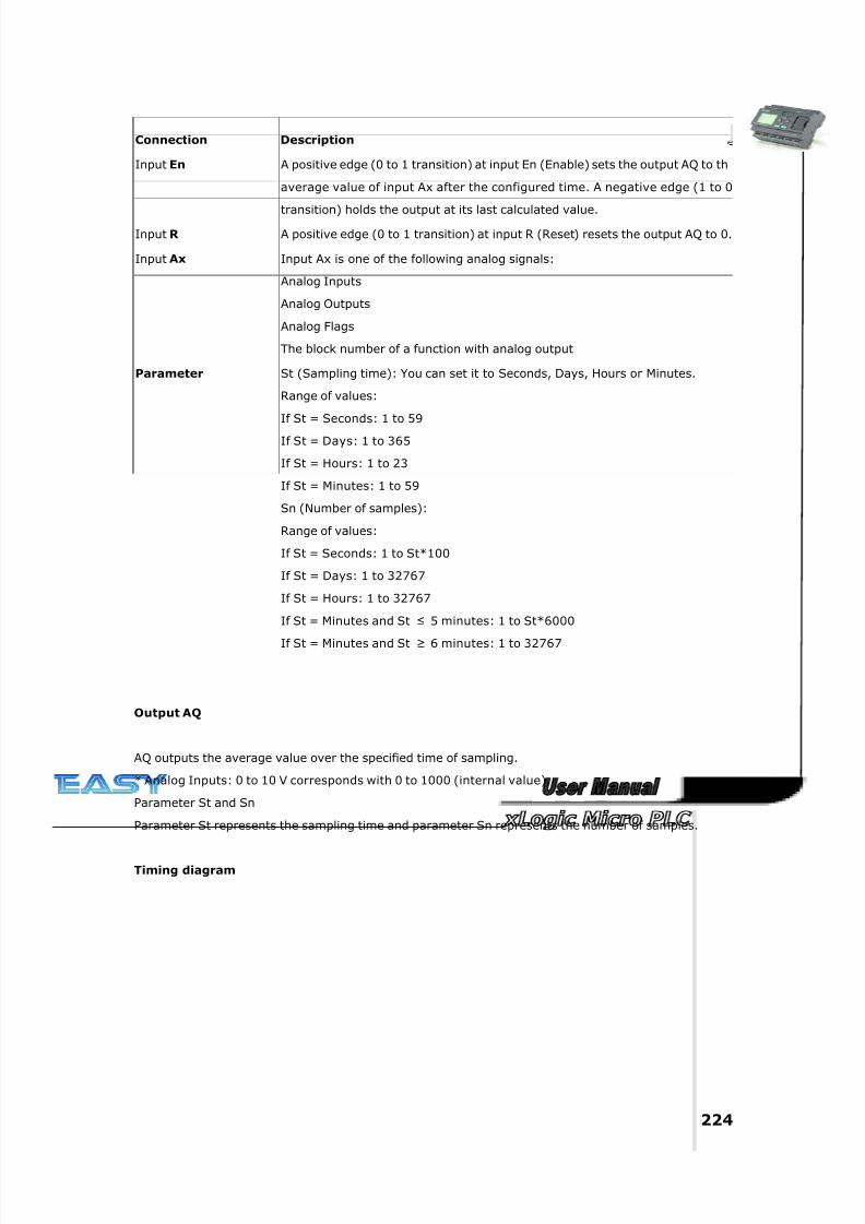
8/20/2019 XLogic User's Manual2
http://slidepdf.com/reader/full/xlogic-users-manual2 224/338
224
Connection Description
Input En A positive edge (0 to 1 transition) at input En (Enable) sets the output AQ to th
average value of input Ax after the configured time. A negative edge (1 to 0
transition) holds the output at its last calculated value.
Input R A positive edge (0 to 1 transition) at input R (Reset) resets the output AQ to 0.
Input Ax Input Ax is one of the following analog signals:
Analog Inputs
Analog Outputs
Analog Flags
The block number of a function with analog output
Parameter St (Sampling time): You can set it to Seconds, Days, Hours or Minutes.
Range of values:
If St = Seconds: 1 to 59
If St = Days: 1 to 365
If St = Hours: 1 to 23
If St = Minutes: 1 to 59
Sn (Number of samples):
Range of values:
If St = Seconds: 1 to St*100
If St = Days: 1 to 32767
If St = Hours: 1 to 32767
If St = Minutes and St ≤ 5 minutes: 1 to St*6000
If St = Minutes and St ≥ 6 minutes: 1 to 32767
Output AQ
AQ outputs the average value over the specified time of sampling.
* Analog Inputs: 0 to 10 V corresponds with 0 to 1000 (internal value).
Parameter St and Sn
Parameter St represents the sampling time and parameter Sn represents the number of samples.
Timing diagram
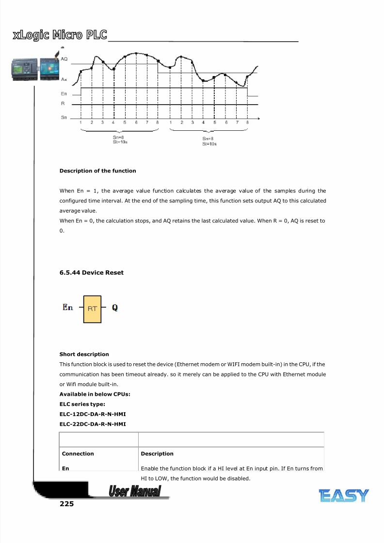
8/20/2019 XLogic User's Manual2
http://slidepdf.com/reader/full/xlogic-users-manual2 225/338
225
Description of the function
When En = 1, the average value function calculates the average value of the samples during the
configured time interval. At the end of the sampling time, this function sets output AQ to this calculated
average value.
When En = 0, the calculation stops, and AQ retains the last calculated value. When R = 0, AQ is reset to
0.
6.5.44 Device Reset
Short description
This function block is used to reset the device (Ethernet modem or WIFI modem built-in) in the CPU, if the
communication has been timeout already. so it merely can be applied to the CPU with Ethernet module
or Wifi module built-in.
Available in below CPUs:
ELC series type:
ELC-12DC-DA-R-N-HMI
ELC-22DC-DA-R-N-HMI
Connection Description
En Enable the function block if a HI level at En input pin. If En turns from
HI to LOW, the function would be disabled.
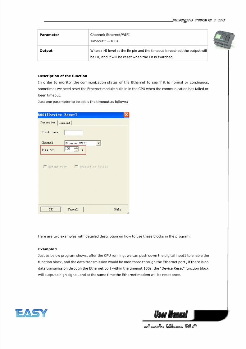
8/20/2019 XLogic User's Manual2
http://slidepdf.com/reader/full/xlogic-users-manual2 226/338
226
Parameter Channel: Ethernet/WIFI
Timeout:1—100s
Output When a HI level at the En pin and the timeout is reached, the output will
be HI, and it will be reset when the En is switched.
Description of the function
In order to monitor the communication status of the Ethernet to see if it is normal or continuous,
sometimes we need reset the Ethernet module built-in in the CPU when the communication has failed or
been timeout.
Just one parameter to be set is the timeout as follows:
Here are two examples with detailed description on how to use these blocks in the program.
Example 1
Just as below program shows, after the CPU running, we can push down the digital input1 to enable the
function block, and the data transmission would be monitored through the Ethernet port , if there is no
data transmission through the Ethernet port within the timeout 100s, the “Device Reset” function block
will output a high signal, and at the same time the Ethernet modem will be reset once.
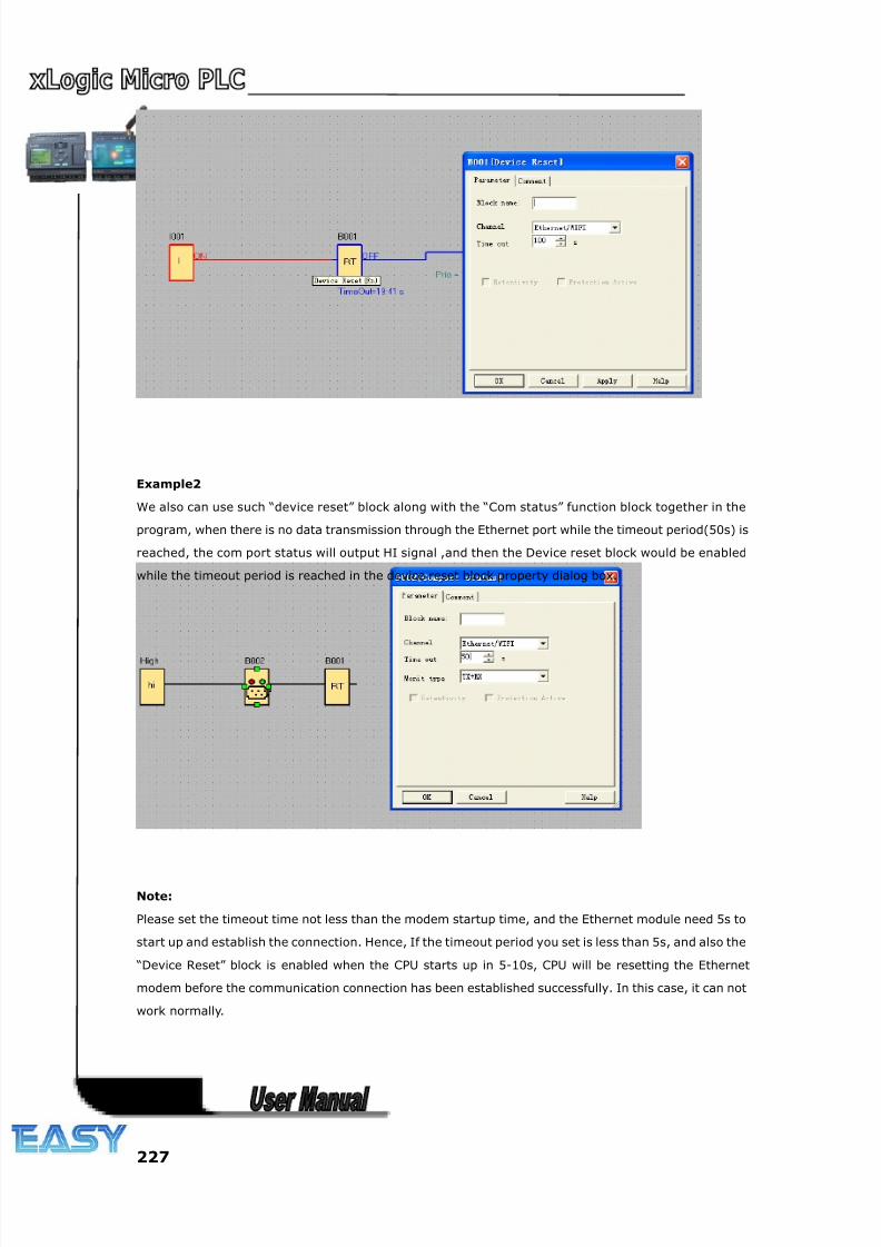
8/20/2019 XLogic User's Manual2
http://slidepdf.com/reader/full/xlogic-users-manual2 227/338
227
Example2
We also can use such “device reset” block along with the “Com status” function block together in the
program, when there is no data transmission through the Ethernet port while the timeout period(50s) is
reached, the com port status will output HI signal ,and then the Device reset block would be enabled
while the timeout period is reached in the device reset block property dialog box.
Note:
Please set the timeout time not less than the modem startup time, and the Ethernet module need 5s to
start up and establish the connection. Hence, If the timeout period you set is less than 5s, and also the
“Device Reset” block is enabled when the CPU starts up in 5-10s, CPU will be resetting the Ethernet
modem before the communication connection has been established successfully. In this case, it can not
work normally.
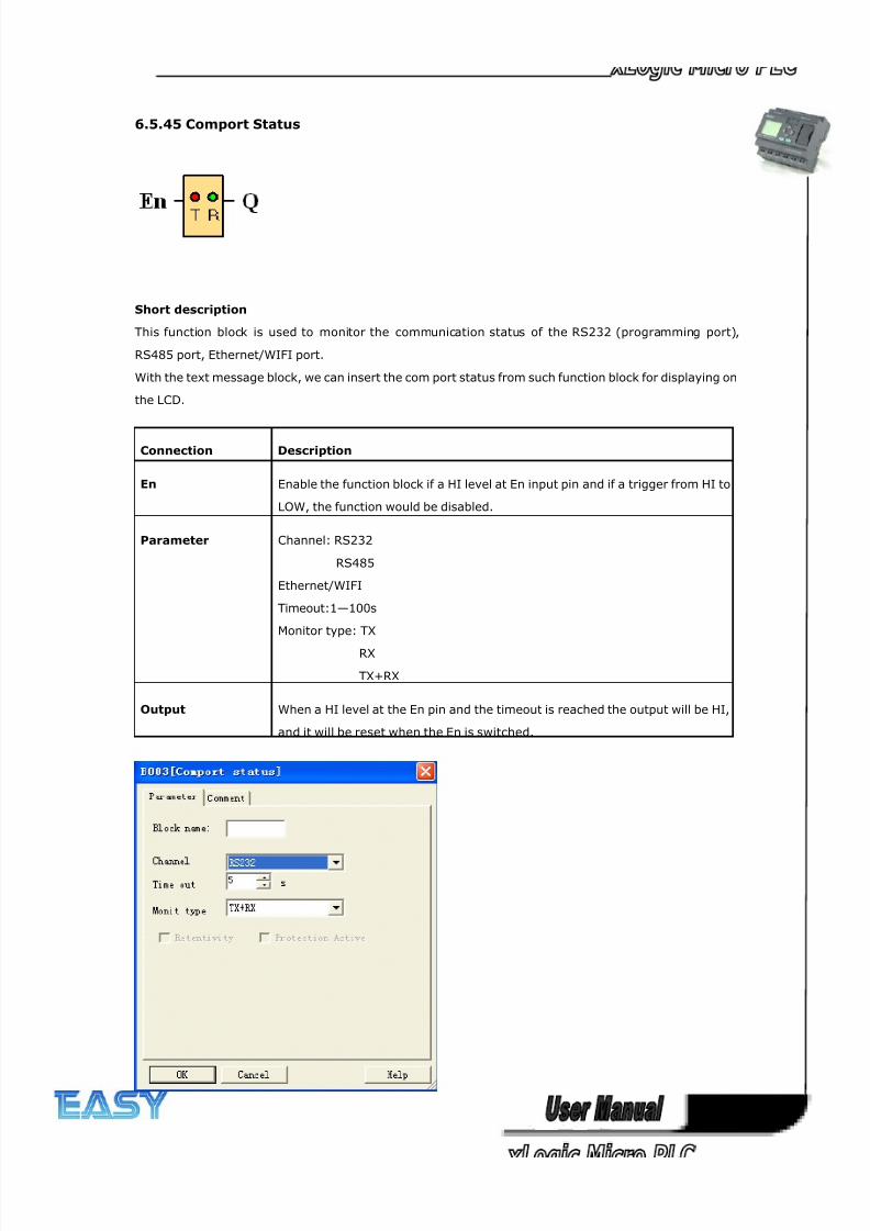
8/20/2019 XLogic User's Manual2
http://slidepdf.com/reader/full/xlogic-users-manual2 228/338
228
6.5.45 Comport Status
Short description
This function block is used to monitor the communication status of the RS232 (programming port),
RS485 port, Ethernet/WIFI port.
With the text message block, we can insert the com port status from such function block for displaying on
the LCD.
Connection Description
En Enable the function block if a HI level at En input pin and if a trigger from HI to
LOW, the function would be disabled.
Parameter Channel: RS232
RS485
Ethernet/WIFI
Timeout:1—100s
Monitor type: TX
RX
TX+RX
Output When a HI level at the En pin and the timeout is reached the output will be HI,
and it will be reset when the En is switched.
8/20/2019 XLogic User's Manual2
http://slidepdf.com/reader/full/xlogic-users-manual2 229/338
229
Parameters
Channel
RS232: This channel is the programming port, it can be used to monitor or display the communication
status of the below accessories:
ELC-RS232 cable
ELC-USB cable
PRO-RS485 cable
ELC-MEMORY
ELC-Copier
RS485: This channel is the RS485 port, it can be used to monitor or display the communication status of
the below accessories:
For Standard ELC-12 Series
ELC12-E-RS485
For ELC-12DC-DA-R-N-HMI CPU
EXM-E-RS485
For ELC-18/22/26 Series CPUs
ELC-RS485
Ethernet: This channel is the Ethernet port, it can be used to monitor or display the communication
status of the LAN port built-in in the CPU:
Timeout 1—100s
Monitor type
Tx : Data from CPU to external devices.
Rx: Data from external device to CPU
Tx+Rx: Data transmission between external device and CPU.
Description of the function
In order to monitor the communication status of the RS232, RS485 and Ethernet port, we can enable
such function block, when the timeout period exceeds, such block shall output a high level trigger.
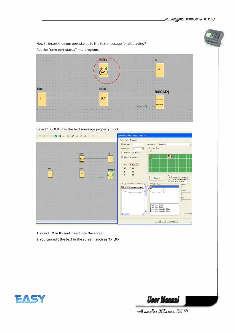
8/20/2019 XLogic User's Manual2
http://slidepdf.com/reader/full/xlogic-users-manual2 230/338
230
How to insert the com port status to the text message for displaying?
Put the “com port status” into program.
Select “BLOCKS” in the text message property block.
1.select TX or Rx and insert into the screen.
2.You can edit the text in the screen, such as TX:,RX:
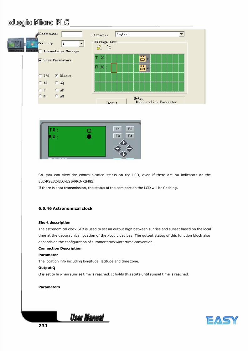
8/20/2019 XLogic User's Manual2
http://slidepdf.com/reader/full/xlogic-users-manual2 231/338
231
So, you can view the communication status on the LCD, even if there are no indicators on the
ELC-RS232/ELC-USB/PRO-RS485.
If there is data transmission, the status of the com port on the LCD will be flashing.
6.5.46 Astronomical clock
Short description
The astronomical clock SFB is used to set an output high between sunrise and sunset based on the local
time at the geographical location of the xLogic devices. The output status of this function block also
depends on the configuration of summer time/wintertime conversion.
Connection Description
Parameter
The location info including longitude, latitude and time zone.
Output Q
Q is set to hi when sunrise time is reached. It holds this state until sunset time is reached.
Parameters
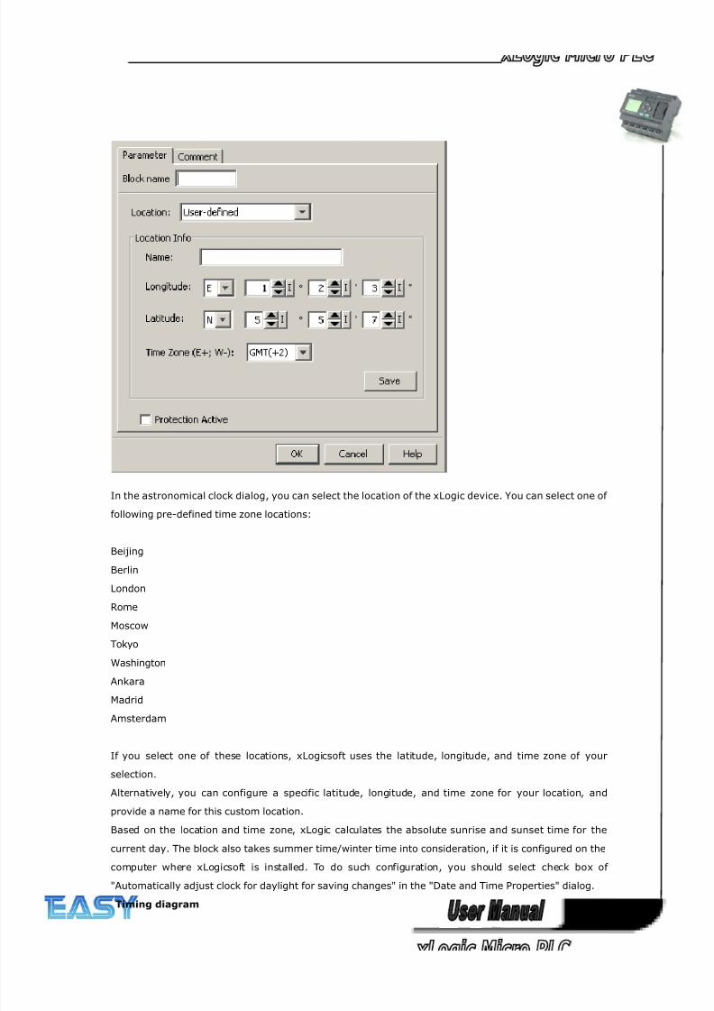
8/20/2019 XLogic User's Manual2
http://slidepdf.com/reader/full/xlogic-users-manual2 232/338
232
In the astronomical clock dialog, you can select the location of the xLogic device. You can select one of
following pre-defined time zone locations:
Beijing
Berlin
London
Rome
Moscow
Tokyo
Washington
Ankara
Madrid
Amsterdam
If you select one of these locations, xLogicsoft uses the latitude, longitude, and time zone of your
selection.
Alternatively, you can configure a specific latitude, longitude, and time zone for your location, and
provide a name for this custom location.
Based on the location and time zone, xLogic calculates the absolute sunrise and sunset time for the
current day. The block also takes summer time/winter time into consideration, if it is configured on the
computer where xLogicsoft is installed. To do such configuration, you should select check box of
"Automatically adjust clock for daylight for saving changes" in the "Date and Time Properties" dialog.
Timing diagram
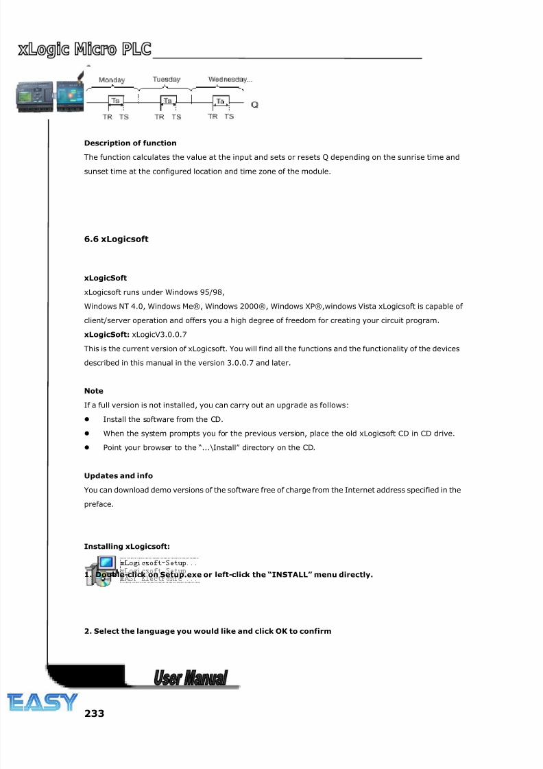
8/20/2019 XLogic User's Manual2
http://slidepdf.com/reader/full/xlogic-users-manual2 233/338
233
Description of function
The function calculates the value at the input and sets or resets Q depending on the sunrise time and
sunset time at the configured location and time zone of the module.
6.6 xLogicsoft
xLogicSoft
xLogicsoft runs under Windows 95/98,
Windows NT 4.0, Windows Me®, Windows 2000®, Windows XP®,windows Vista xLogicsoft is capable of
client/server operation and offers you a high degree of freedom for creating your circuit program.
xLogicSoft: xLogicV3.0.0.7
This is the current version of xLogicsoft. You will find all the functions and the functionality of the devices
described in this manual in the version 3.0.0.7 and later.
Note
If a full version is not installed, you can carry out an upgrade as follows:
Install the software from the CD.
When the system prompts you for the previous version, place the old xLogicsoft CD in CD drive.
Point your browser to the “...\Install” directory on the CD.
Updates and info
You can download demo versions of the software free of charge from the Internet address specified in the
preface.
Installing xLogicsoft:
1. Double-click on Setup.exe or left-click the “INSTALL” menu directly.
2. Select the language you would like and click OK to confirm
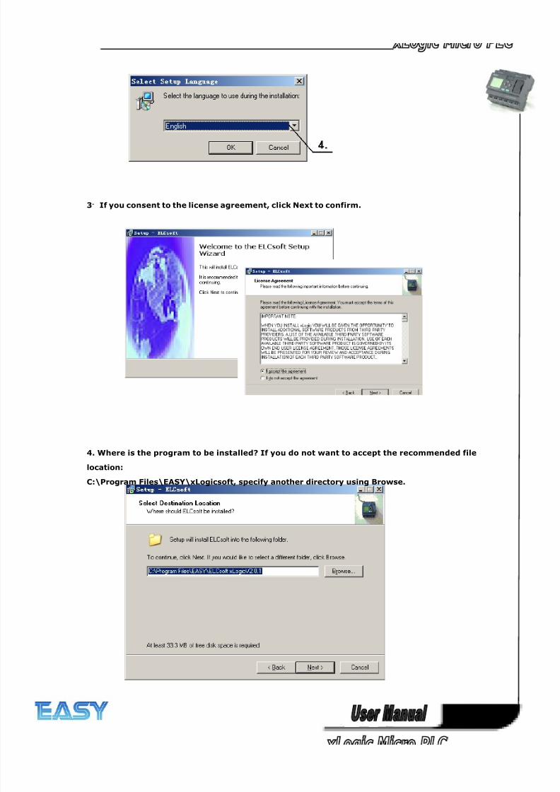
8/20/2019 XLogic User's Manual2
http://slidepdf.com/reader/full/xlogic-users-manual2 234/338
234
3.
If you consent to the license agreement, click Next to confirm.
4. Where is the program to be installed? If you do not want to accept the recommended file
location:
C:\Program Files\EASY\xLogicsoft, specify another directory using Browse.
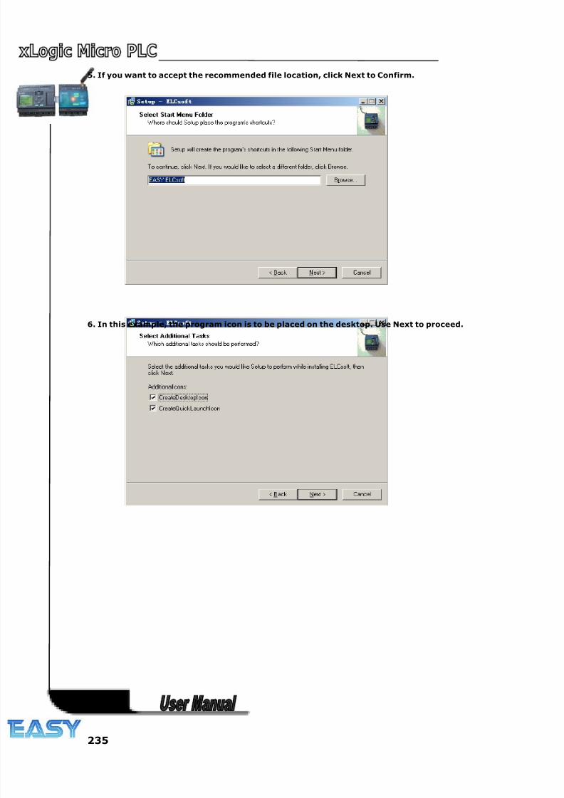
8/20/2019 XLogic User's Manual2
http://slidepdf.com/reader/full/xlogic-users-manual2 235/338
235
5. If you want to accept the recommended file location, click Next to Confirm.
6. In this example, the program icon is to be placed on the desktop. Use Next to proceed.
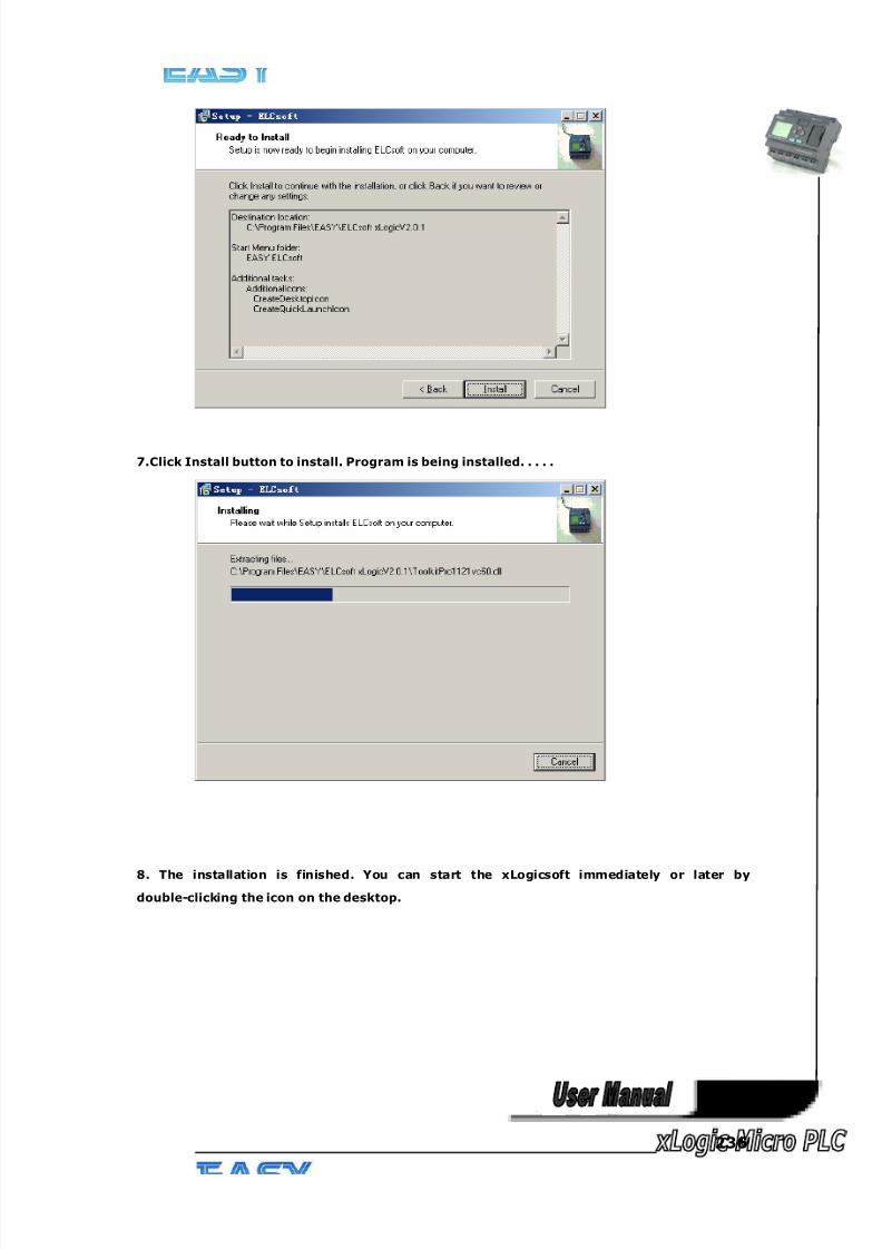
8/20/2019 XLogic User's Manual2
http://slidepdf.com/reader/full/xlogic-users-manual2 236/338
236
7.Click Install button to install. Program is being installed. . . . .
8. The installation is finished. You can start the xLogicsoft immediately or later by
double-clicking the icon on the desktop.

8/20/2019 XLogic User's Manual2
http://slidepdf.com/reader/full/xlogic-users-manual2 237/338
237
You now see the complete user interface of xLogicsoft The programming interface for creating your
circuit programs occupies the greater part of the screen. The icons and logical links of the circuit program
are arranged on this programming interface.
To help you to maintain an overview of large circuit programs, the right side and the bottom of theprogramming interface contains scroll bars, which you can use for vertical and horizontal scrolling of the
circuit program.
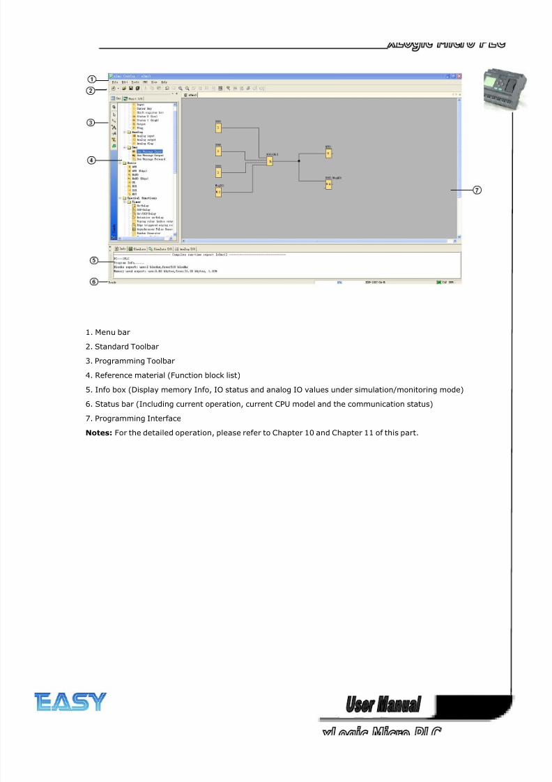
8/20/2019 XLogic User's Manual2
http://slidepdf.com/reader/full/xlogic-users-manual2 238/338
238
1. Menu bar
2. Standard Toolbar
3. Programming Toolbar
4. Reference material (Function block list)
5. Info box (Display memory Info, IO status and analog IO values under simulation/monitoring mode)
6. Status bar (Including current operation, current CPU model and the communication status)
7. Programming Interface
Notes: For the detailed operation, please refer to Chapter 10 and Chapter 11 of this part.
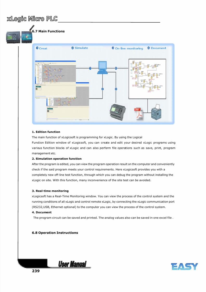
8/20/2019 XLogic User's Manual2
http://slidepdf.com/reader/full/xlogic-users-manual2 239/338
239
6.7 Main Functions
1. Edition function
The main function of xLogicsoft is programming for xLogic. By using the Logical
Function Edition window of xLogicsoft, you can create and edit your desired xLogic programs using
various function blocks of xLogic and can also perform file operations such as save, print, program
management etc.
2. Simulation operation function
After the program is edited, you can view the program operation result on the computer and conveniently
check if the said program meets your control requirements. Here xLogicsoft provides you with a
completely new off-line test function, through which you can debug the program without installing the
xLogic on site. With this function, many inconvenience of the site test can be avoided.
3. Real-time monitoring
xLogicsoft has a Real-Time Monitoring window. You can view the process of the control system and the
running conditions of all xLogic and control remote xLogic, by connecting the xLogic communication port
(RS232,USB, Ethernet optional) to the computer you can view the process of the control system.
4. Document
The program circuit can be saved and printed. The analog values also can be saved in one excel file .
6.8 Operation Instructions
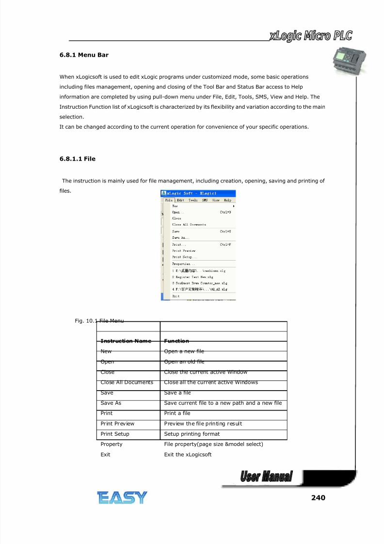
8/20/2019 XLogic User's Manual2
http://slidepdf.com/reader/full/xlogic-users-manual2 240/338
240
6.8.1 Menu Bar
When xLogicsoft is used to edit xLogic programs under customized mode, some basic operations
including files management, opening and closing of the Tool Bar and Status Bar access to Help
information are completed by using pull-down menu under File, Edit, Tools, SMS, View and Help. The
Instruction Function list of xLogicsoft is characterized by its flexibility and variation according to the main
selection.
It can be changed according to the current operation for convenience of your specific operations.
6.8.1.1 File
The instruction is mainly used for file management, including creation, opening, saving and printing of
files.
Fig. 10.1 File Menu
Instruction Name Function
New Open a new file
Open Open an old file
Close Close the current active Window
Close All Documents Close all the current active Windows
Save Save a file
Save As Save current file to a new path and a new file
Print Print a file
Print Preview Preview the file printing result
Print Setup Setup printing format
Property File property(page size &model select)
Exit Exit the xLogicsoft
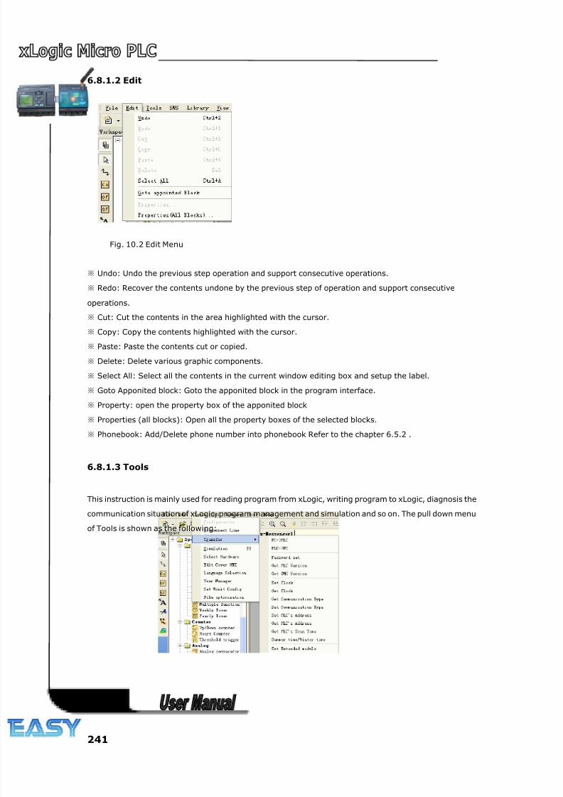
8/20/2019 XLogic User's Manual2
http://slidepdf.com/reader/full/xlogic-users-manual2 241/338
241
6.8.1.2 Edit
Fig. 10.2 Edit Menu
※ Undo: Undo the previous step operation and support consecutive operations.
※ Redo: Recover the contents undone by the previous step of operation and support consecutive
operations.
※ Cut: Cut the contents in the area highlighted with the cursor.
※ Copy: Copy the contents highlighted with the cursor.
※ Paste: Paste the contents cut or copied.
※ Delete: Delete various graphic components.
※ Select All: Select all the contents in the current window editing box and setup the label.
※ Goto Apponited block: Goto the apponited block in the program interface.
※ Property: open the property box of the apponited block
※ Properties (all blocks): Open all the property boxes of the selected blocks.
※ Phonebook: Add/Delete phone number into phonebook Refer to the chapter 6.5.2 .
6.8.1.3 Tools
This instruction is mainly used for reading program from xLogic, writing program to xLogic, diagnosis the
communication situation of xLogic, program management and simulation and so on. The pull down menu
of Tools is shown as the following:
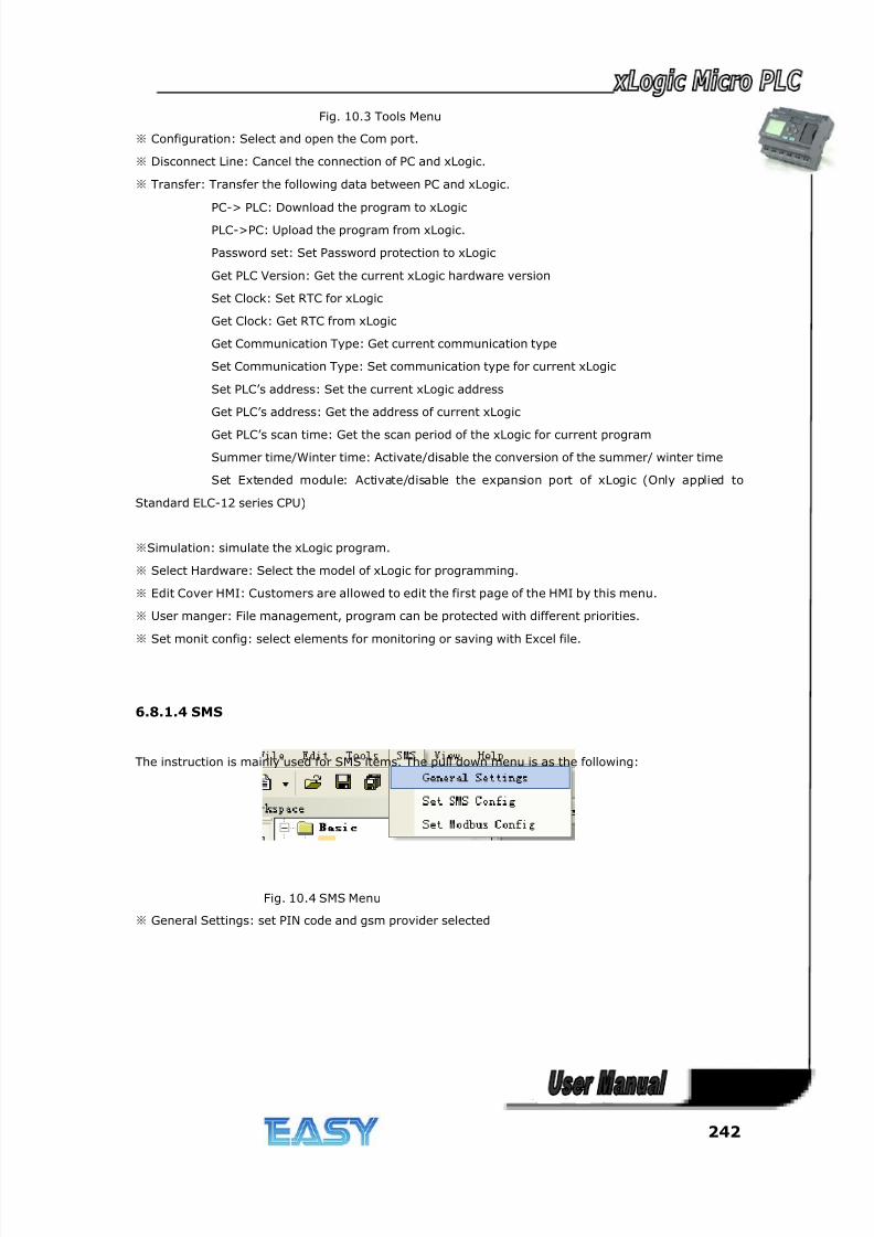
8/20/2019 XLogic User's Manual2
http://slidepdf.com/reader/full/xlogic-users-manual2 242/338
242
Fig. 10.3 Tools Menu
※ Configuration: Select and open the Com port.
※ Disconnect Line: Cancel the connection of PC and xLogic.
※ Transfer: Transfer the following data between PC and xLogic.
PC-> PLC: Download the program to xLogic
PLC->PC: Upload the program from xLogic.
Password set: Set Password protection to xLogic
Get PLC Version: Get the current xLogic hardware version
Set Clock: Set RTC for xLogic
Get Clock: Get RTC from xLogic
Get Communication Type: Get current communication type
Set Communication Type: Set communication type for current xLogic
Set PLC’s address: Set the current xLogic address
Get PLC’s address: Get the address of current xLogic
Get PLC’s scan time: Get the scan period of the xLogic for current program
Summer time/Winter time: Activate/disable the conversion of the summer/ winter time
Set Extended module: Activate/disable the expansion port of xLogic (Only applied to
Standard ELC-12 series CPU)
※Simulation: simulate the xLogic program.
※ Select Hardware: Select the model of xLogic for programming.
※ Edit Cover HMI: Customers are allowed to edit the first page of the HMI by this menu.
※ User manger: File management, program can be protected with different priorities.
※ Set monit config: select elements for monitoring or saving with Excel file.
6.8.1.4 SMS
The instruction is mainly used for SMS items. The pull down menu is as the following:
Fig. 10.4 SMS Menu
※ General Settings: set PIN code and gsm provider selected
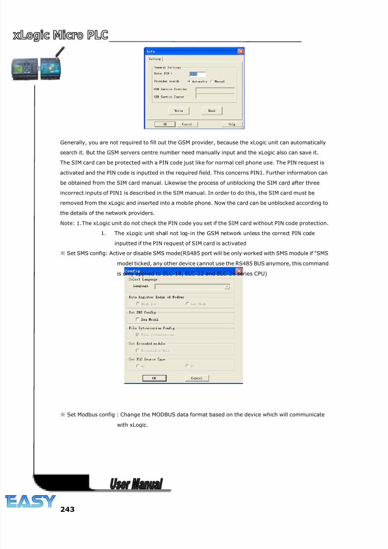
8/20/2019 XLogic User's Manual2
http://slidepdf.com/reader/full/xlogic-users-manual2 243/338
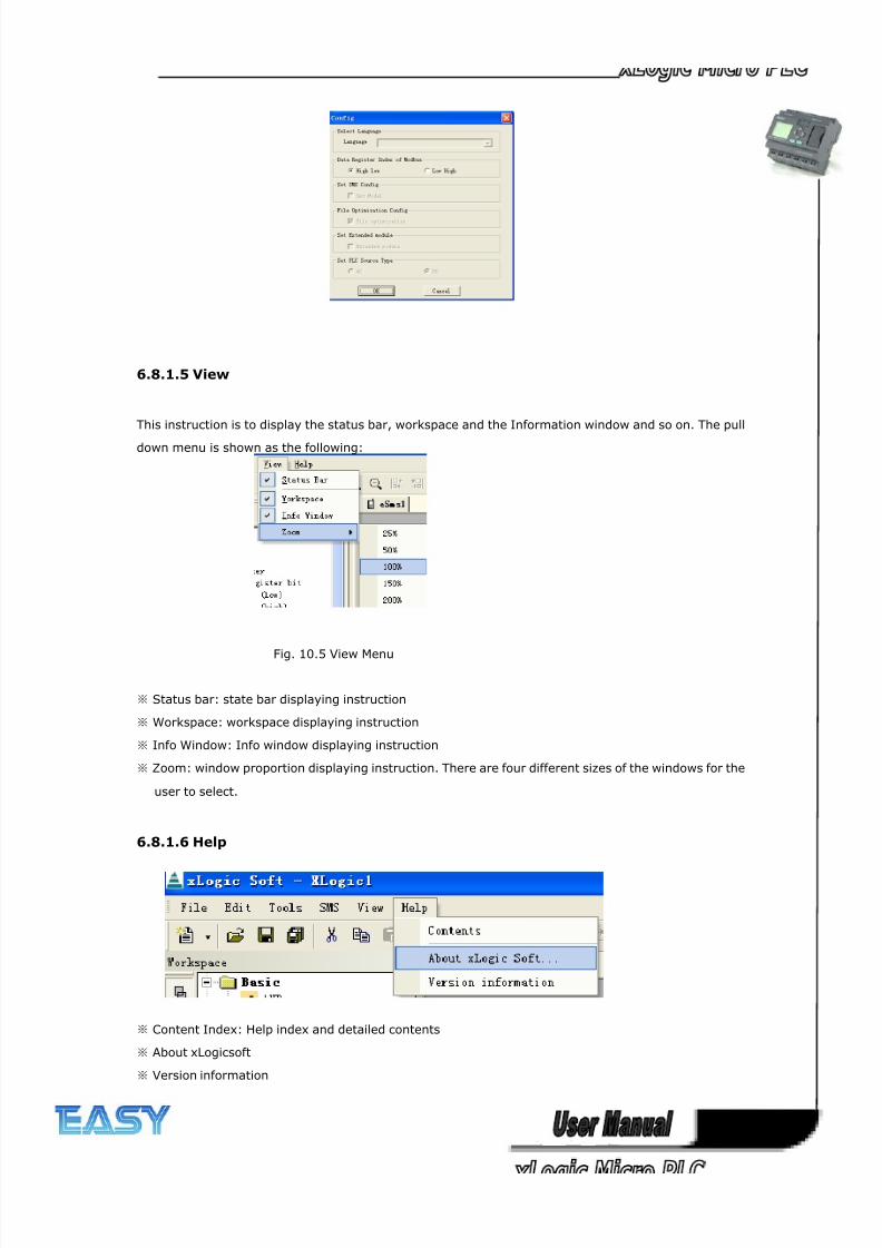
8/20/2019 XLogic User's Manual2
http://slidepdf.com/reader/full/xlogic-users-manual2 244/338
244
6.8.1.5 View
This instruction is to display the status bar, workspace and the Information window and so on. The pull
down menu is shown as the following:
Fig. 10.5 View Menu
※ Status bar: state bar displaying instruction
※ Workspace: workspace displaying instruction
※ Info Window: Info window displaying instruction
※ Zoom: window proportion displaying instruction. There are four different sizes of the windows for the
user to select.
6.8.1.6 Help
※ Content Index: Help index and detailed contents
※ About xLogicsoft
※ Version information
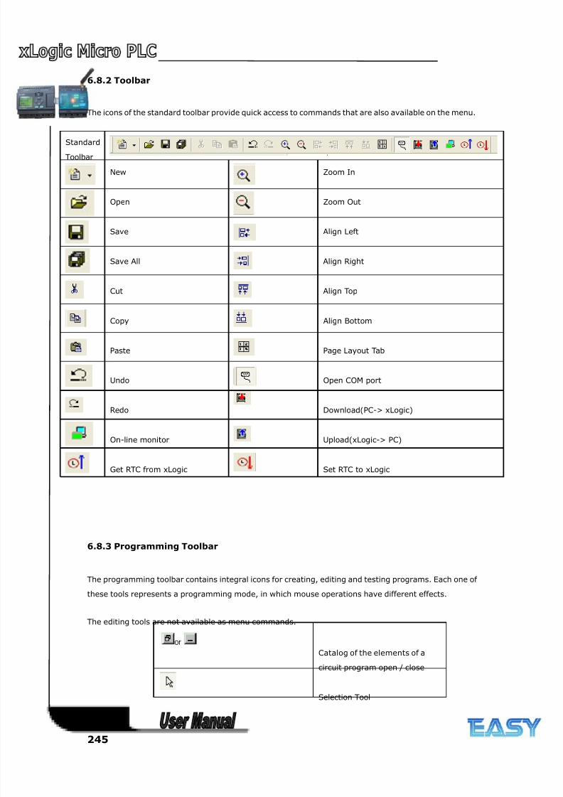
8/20/2019 XLogic User's Manual2
http://slidepdf.com/reader/full/xlogic-users-manual2 245/338
245
6.8.2 Toolbar
The icons of the standard toolbar provide quick access to commands that are also available on the menu.
Standard
Toolbar
New Zoom In
Open Zoom Out
Save Align Left
Save All Align Right
Cut Align Top
Copy Align Bottom
Paste Page Layout Tab
Undo Open COM port
Redo Download(PC-> xLogic)
On-line monitor Upload(xLogic-> PC)
Get RTC from xLogic Set RTC to xLogic
6.8.3 Programming Toolbar
The programming toolbar contains integral icons for creating, editing and testing programs. Each one of
these tools represents a programming mode, in which mouse operations have different effects.
The editing tools are not available as menu commands.
Catalog of the elements of a
circuit program open / close
Selection Tool
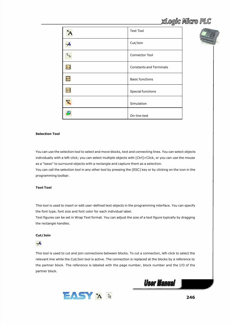
8/20/2019 XLogic User's Manual2
http://slidepdf.com/reader/full/xlogic-users-manual2 246/338
246
Text Tool
Cut/Join
Connector Tool
Constants and Terminals
Basic functions
Special functions
Simulation
On-line test
Selection Tool
You can use the selection tool to select and move blocks, text and connecting lines. You can select objects
individually with a left-click; you can select multiple objects with [Ctrl]+Click, or you can use the mouse
as a "lasso" to surround objects with a rectangle and capture them as a selection.
You can call the selection tool in any other tool by pressing the [ESC] key or by clicking on the icon in theprogramming toolbar.
Text Tool
This tool is used to insert or edit user-defined text objects in the programming interface. You can specify
the font type, font size and font color for each individual label.
Text figures can be set in Wrap Text format. You can adjust the size of a text figure typically by dragging
the rectangle handles.
Cut/Join
This tool is used to cut and join connections between blocks. To cut a connection, left-click to select the
relevant line while the Cut/Join tool is active. The connection is replaced at the blocks by a reference to
the partner block. The reference is labeled with the page number, block number and the I/O of the
partner block.
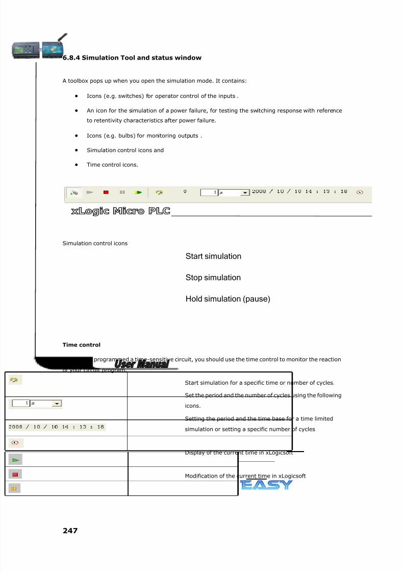
8/20/2019 XLogic User's Manual2
http://slidepdf.com/reader/full/xlogic-users-manual2 247/338
247
6.8.4 Simulation Tool and status window
A toolbox pops up when you open the simulation mode. It contains:
• Icons (e.g. switches) for operator control of the inputs .
• An icon for the simulation of a power failure, for testing the switching response with reference
to retentivity characteristics after power failure.
• Icons (e.g. bulbs) for monitoring outputs .
• Simulation control icons and
• Time control icons.
Simulation control icons
Start simulation
Stop simulation
Hold simulation (pause)
Time control
If you have programmed a time-sensitive circuit, you should use the time control to monitor the reaction
of your circuit program.
Start simulation for a specific time or number of cycles.
Set the period and the number of cycles using the following
icons.
Setting the period and the time base for a time limited
simulation or setting a specific number of cycles
Display of the current time in xLogicsoft
Modification of the current time in xLogicsoft
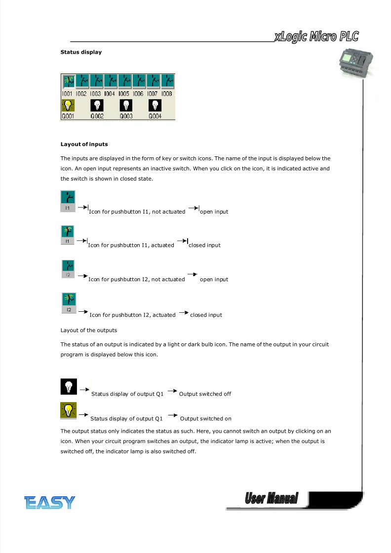
8/20/2019 XLogic User's Manual2
http://slidepdf.com/reader/full/xlogic-users-manual2 248/338
248
Status display
Layout of inputs
The inputs are displayed in the form of key or switch icons. The name of the input is displayed below the
icon. An open input represents an inactive switch. When you click on the icon, it is indicated active and
the switch is shown in closed state.
Icon for pushbutton I1, not actuated open input
Icon for pushbutton I1, actuated closed input
Icon for pushbutton I2, not actuated open input
Icon for pushbutton I2, actuated closed input
Layout of the outputs
The status of an output is indicated by a light or dark bulb icon. The name of the output in your circuit
program is displayed below this icon.
Status display of output Q1 Output switched off
Status display of output Q1 Output switched on
The output status only indicates the status as such. Here, you cannot switch an output by clicking on an
icon. When your circuit program switches an output, the indicator lamp is active; when the output is
switched off, the indicator lamp is also switched off.
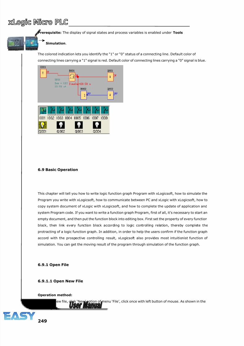
8/20/2019 XLogic User's Manual2
http://slidepdf.com/reader/full/xlogic-users-manual2 249/338
249
Prerequisite: The display of signal states and process variables is enabled under Tools
Simulation.
The colored indication lets you identify the "1" or "0" status of a connecting line. Default color of
connecting lines carrying a "1" signal is red. Default color of connecting lines carrying a "0" signal is blue.
6.9 Basic Operation
This chapter will tell you how to write logic function graph Program with xLogicsoft, how to simulate the
Program you write with xLogicsoft, how to communicate between PC and xLogic with xLogicsoft, how to
copy system document of xLogic with xLogicsoft, and how to complete the update of application and
system Program code. If you want to write a function graph Program, first of all, it’s necessary to start an
empty document, and then put the function block into editing box. First set the property of every function
block, then link every function block according to logic controlling relation, thereby complete the
protracting of a logic function graph. In addition, in order to help the users confirm if the function graph
accord with the prospective controlling result, xLogicsoft also provides most intuitionist function of
simulation. You can get the moving result of the program through simulation of the function graph.
6.9.1 Open File
6.9.1.1 Open New File
Operation method:
To open a new file, click ‘New’ option of menu ‘File’, click once with left button of mouse. As shown in thefollowing fig.
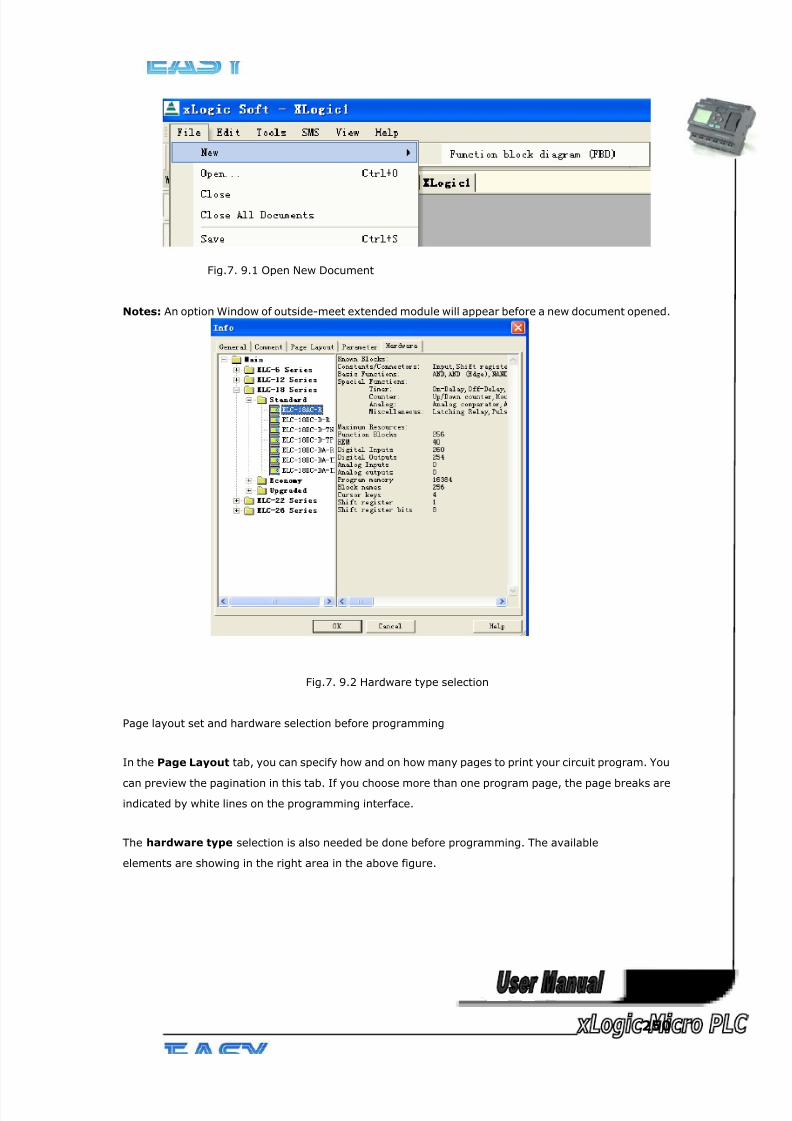
8/20/2019 XLogic User's Manual2
http://slidepdf.com/reader/full/xlogic-users-manual2 250/338
250
Fig.7. 9.1 Open New Document
Notes: An option Window of outside-meet extended module will appear before a new document opened.
Fig.7. 9.2 Hardware type selection
Page layout set and hardware selection before programming
In the Page Layout tab, you can specify how and on how many pages to print your circuit program. You
can preview the pagination in this tab. If you choose more than one program page, the page breaks are
indicated by white lines on the programming interface.
The hardware type selection is also needed be done before programming. The available
elements are showing in the right area in the above figure.
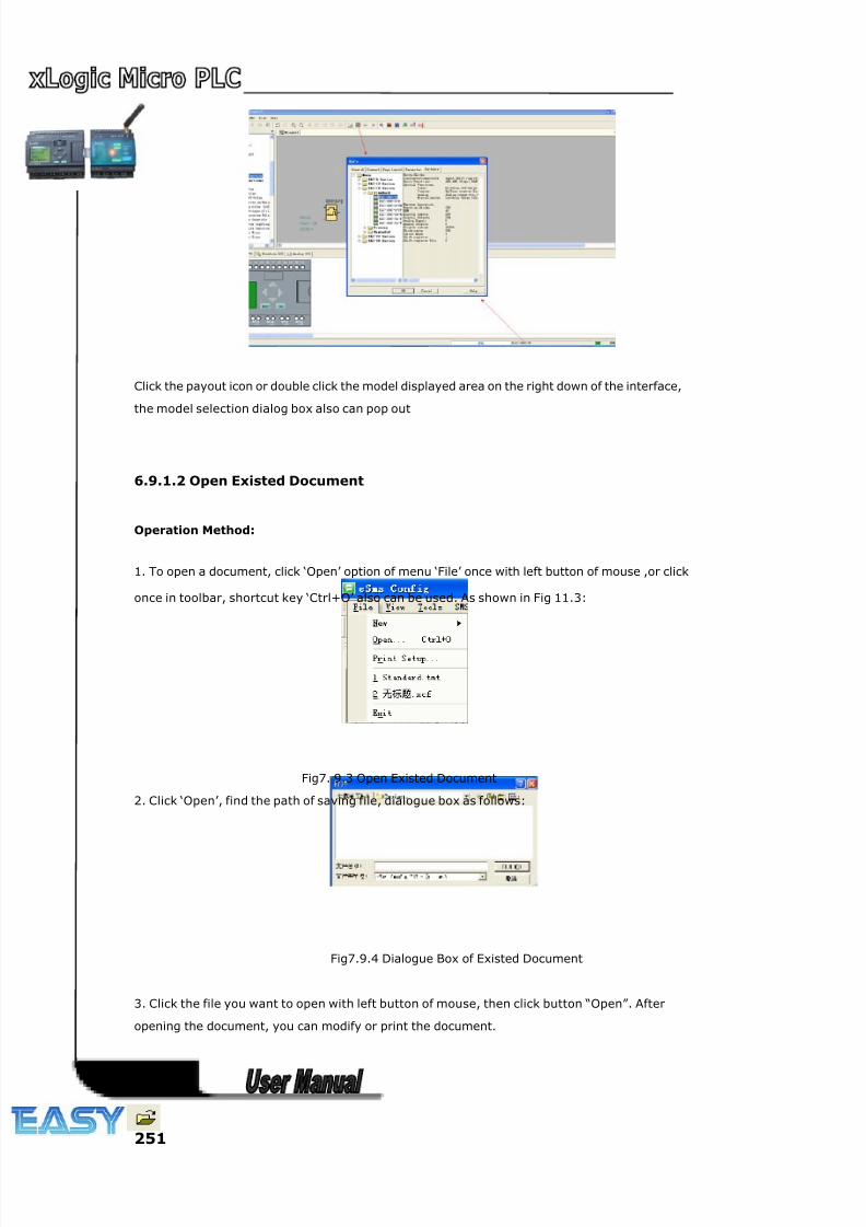
8/20/2019 XLogic User's Manual2
http://slidepdf.com/reader/full/xlogic-users-manual2 251/338
251
Click the payout icon or double click the model displayed area on the right down of the interface,
the model selection dialog box also can pop out
6.9.1.2 Open Existed Document
Operation Method:
1. To open a document, click ‘Open’ option of menu ‘File’ once with left button of mouse ,or click
once in toolbar, shortcut key ‘Ctrl+O’ also can be used. As shown in Fig 11.3:
Fig7. 9.3 Open Existed Document
2. Click ‘Open’, find the path of saving file, dialogue box as follows:
Fig7.9.4 Dialogue Box of Existed Document
3. Click the file you want to open with left button of mouse, then click button “Open”. After
opening the document, you can modify or print the document.
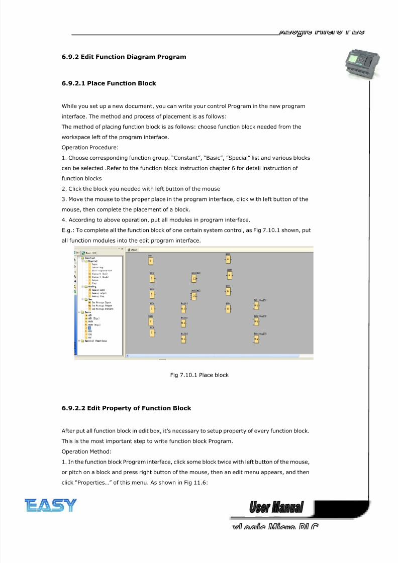
8/20/2019 XLogic User's Manual2
http://slidepdf.com/reader/full/xlogic-users-manual2 252/338
252
6.9.2 Edit Function Diagram Program
6.9.2.1 Place Function Block
While you set up a new document, you can write your control Program in the new program
interface. The method and process of placement is as follows:
The method of placing function block is as follows: choose function block needed from the
workspace left of the program interface.
Operation Procedure:
1. Choose corresponding function group. “Constant”, “Basic”, ”Special” list and various blocks
can be selected .Refer to the function block instruction chapter 6 for detail instruction of
function blocks
2. Click the block you needed with left button of the mouse
3. Move the mouse to the proper place in the program interface, click with left button of the
mouse, then complete the placement of a block.
4. According to above operation, put all modules in program interface.
E.g.: To complete all the function block of one certain system control, as Fig 7.10.1 shown, put
all function modules into the edit program interface.
Fig 7.10.1 Place block
6.9.2.2 Edit Property of Function Block
After put all function block in edit box, it’s necessary to setup property of every function block.
This is the most important step to write function block Program.
Operation Method:
1. In the function block Program interface, click some block twice with left button of the mouse,
or pitch on a block and press right button of the mouse, then an edit menu appears, and then
click “Properties…” of this menu. As shown in Fig 11.6:
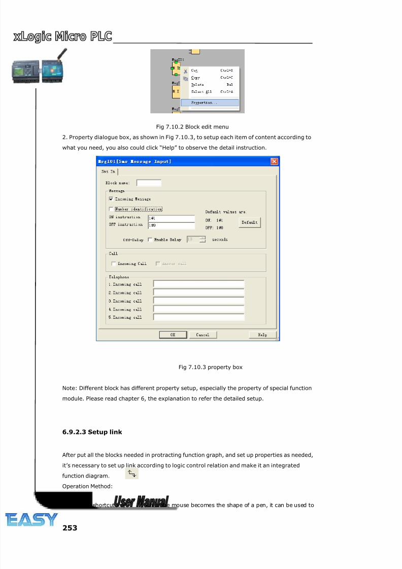
8/20/2019 XLogic User's Manual2
http://slidepdf.com/reader/full/xlogic-users-manual2 253/338
253
Fig 7.10.2 Block edit menu
2. Property dialogue box, as shown in Fig 7.10.3, to setup each item of content according to
what you need, you also could click “Help” to observe the detail instruction.
Fig 7.10.3 property box
Note: Different block has different property setup, especially the property of special function
module. Please read chapter 6, the explanation to refer the detailed setup.
6.9.2.3 Setup link
After put all the blocks needed in protracting function graph, and set up properties as needed,
it’s necessary to set up link according to logic control relation and make it an integrated
function diagram.
Operation Method:
1. Pitch on shortcut key , when the mouse becomes the shape of a pen, it can be used to
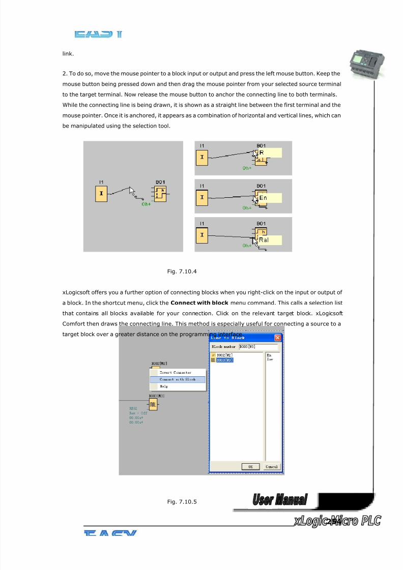
8/20/2019 XLogic User's Manual2
http://slidepdf.com/reader/full/xlogic-users-manual2 254/338
254
link.
2. To do so, move the mouse pointer to a block input or output and press the left mouse button. Keep the
mouse button being pressed down and then drag the mouse pointer from your selected source terminal
to the target terminal. Now release the mouse button to anchor the connecting line to both terminals.
While the connecting line is being drawn, it is shown as a straight line between the first terminal and the
mouse pointer. Once it is anchored, it appears as a combination of horizontal and vertical lines, which can
be manipulated using the selection tool.
Fig. 7.10.4
xLogicsoft offers you a further option of connecting blocks when you right-click on the input or output of
a block. In the shortcut menu, click the Connect with block menu command. This calls a selection list
that contains all blocks available for your connection. Click on the relevant target block. xLogicsoft
Comfort then draws the connecting line. This method is especially useful for connecting a source to a
target block over a greater distance on the programming interface.
Fig. 7.10.5
8/20/2019 XLogic User's Manual2
http://slidepdf.com/reader/full/xlogic-users-manual2 255/338
255
Tips on connecting blocks
1. Move the mouse pointer over a block and briefly hold it in this position. The name of the block is shown.
The name of the block input appears when you move the mouse pointer onto the input.
2. To make it easier for you to interconnect blocks, a blue frame around the mouse pointer pops when it
is "captured" by a pin.
Rules for connecting blocks
The following rules apply to the connection of blocks:
1. You can connect a single input to multiple outputs.
2. You cannot connect multiple inputs to a single output.
You cannot interconnect I/O in the same path of a circuit program. Recursion is not permitted.
Interconnect a flag or output if necessary.
Special function blocks also have green "connectors". These do not represent connecting pins, but are
used instead for assigning the parameter settings.
Analog I/O cannot be connected to digital I/O.
6.9.2.4 Delete Function Block or Delete Link
When you put some needless block in program interface or link some default ones, you need to
delete them as follows:
1. Pitch on module or link to delete with mouse.
2. Press “Delete” in the keyboard, or click right button of the mouse, select option
“Delete” in the menu, then you can delete the module or link.
6.10 Simulation Running
xLogicsoft could edit function diagram, and perform function of simulation operation.
After you finish the edit, you can start the function of simulation operation, to
examine program to see if it performs your control logic or not.
Operation Method:
1.Click “Simulation” under the menu “Tools” with left button of the mouse . It’s time to start
program of simulation, or click “ ” in the simulation toolbar with mouse, and it also can open
simulation operation interface. It shows as Fig. 11.9.
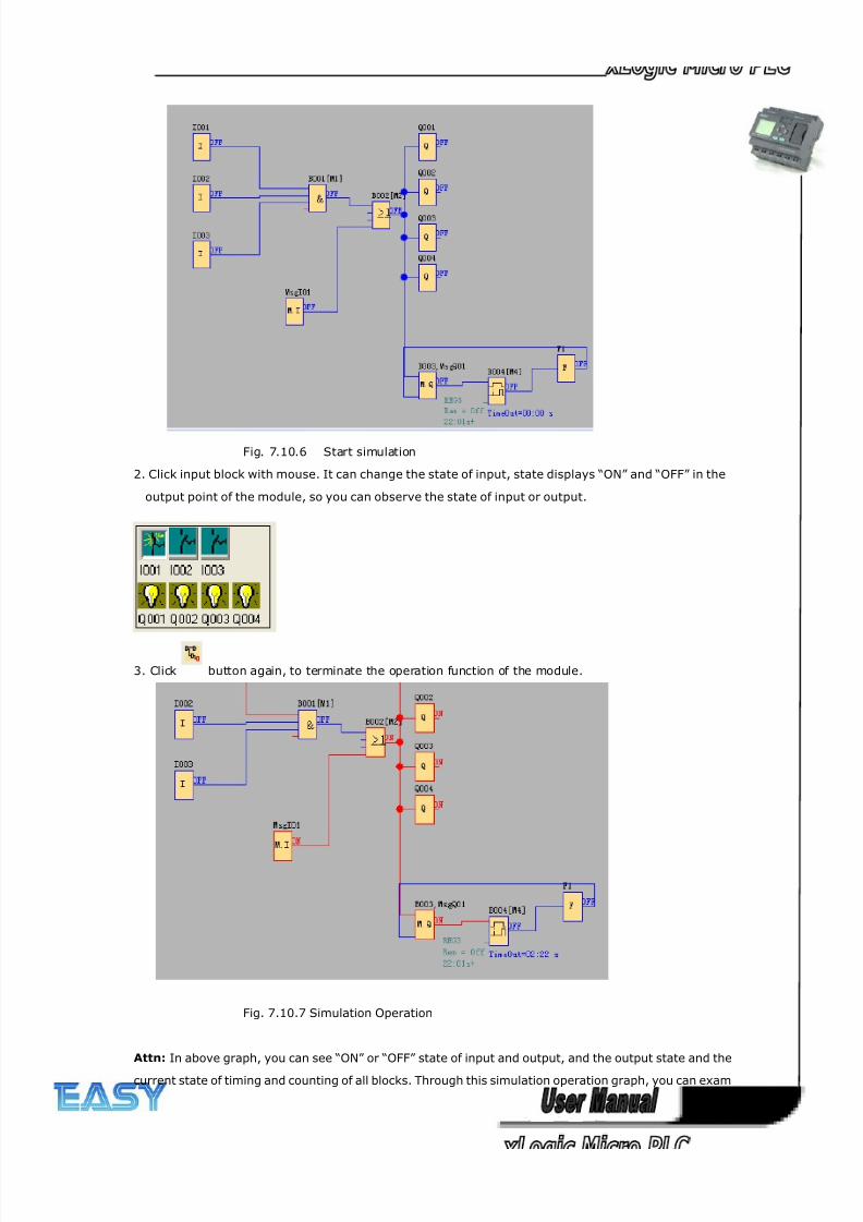
8/20/2019 XLogic User's Manual2
http://slidepdf.com/reader/full/xlogic-users-manual2 256/338
256
Fig. 7.10.6 Start simulation
2. Click input block with mouse. It can change the state of input, state displays “ON” and “OFF” in the
output point of the module, so you can observe the state of input or output.
3. Click button again, to terminate the operation function of the module.
Fig. 7.10.7 Simulation Operation
Attn: In above graph, you can see “ON” or “OFF” state of input and output, and the output state and the
current state of timing and counting of all blocks. Through this simulation operation graph, you can exam
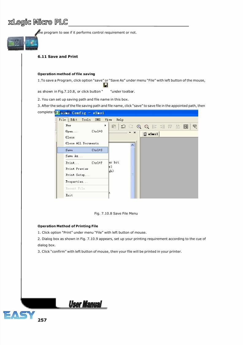
8/20/2019 XLogic User's Manual2
http://slidepdf.com/reader/full/xlogic-users-manual2 257/338
257
the program to see if it performs control requirement or not.
6.11 Save and Print
Operation method of file saving
1.To save a Program, click option “save” or “Save As” under menu “File” with left button of the mouse,
as shown in Fig.7.10.8, or click button “ ”under toolbar.
2. You can set up saving path and file name in this box.
3. After the setup of the file saving path and file name, click “save” to save file in the appointed path, then
complete to save file.
Fig. 7.10.8 Save File Menu
Operation Method of Printing File
1. Click option “Print” under menu “File” with left button of mouse.
2. Dialog box as shown in Fig. 7.10.9 appears, set up your printing requirement according to the cue of
dialog box.
3. Click “confirm” with left button of mouse, then your file will be printed in your printer.
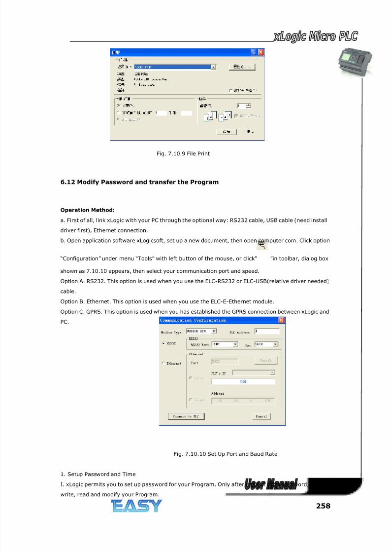
8/20/2019 XLogic User's Manual2
http://slidepdf.com/reader/full/xlogic-users-manual2 258/338
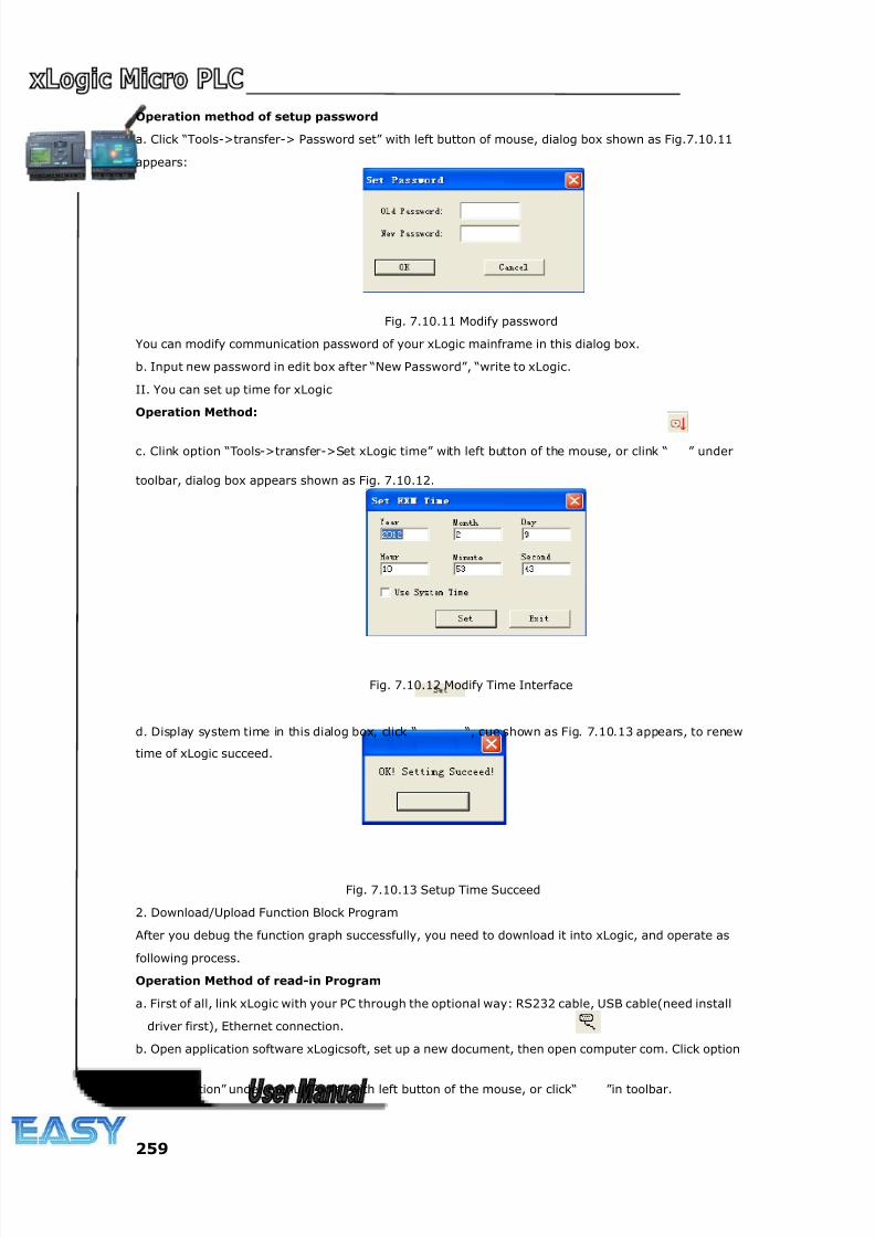
8/20/2019 XLogic User's Manual2
http://slidepdf.com/reader/full/xlogic-users-manual2 259/338
259
Operation method of setup password
a. Click “Tools->transfer-> Password set” with left button of mouse, dialog box shown as Fig.7.10.11
appears:
Fig. 7.10.11 Modify password
You can modify communication password of your xLogic mainframe in this dialog box.
b. Input new password in edit box after “New Password”, “write to xLogic.
II. You can set up time for xLogic
Operation Method:
c. Clink option “Tools->transfer->Set xLogic time” with left button of the mouse, or clink “ ” under
toolbar, dialog box appears shown as Fig. 7.10.12.
Fig. 7.10.12 Modify Time Interface
d. Display system time in this dialog box, click “ “, cue shown as Fig. 7.10.13 appears, to renew
time of xLogic succeed.
Fig. 7.10.13 Setup Time Succeed
2. Download/Upload Function Block Program
After you debug the function graph successfully, you need to download it into xLogic, and operate as
following process.
Operation Method of read-in Program
a. First of all, link xLogic with your PC through the optional way: RS232 cable, USB cable(need install
driver first), Ethernet connection.
b. Open application software xLogicsoft, set up a new document, then open computer com. Click option
“Configuration” under menu “Tools” with left button of the mouse, or click“ ”in toolbar.
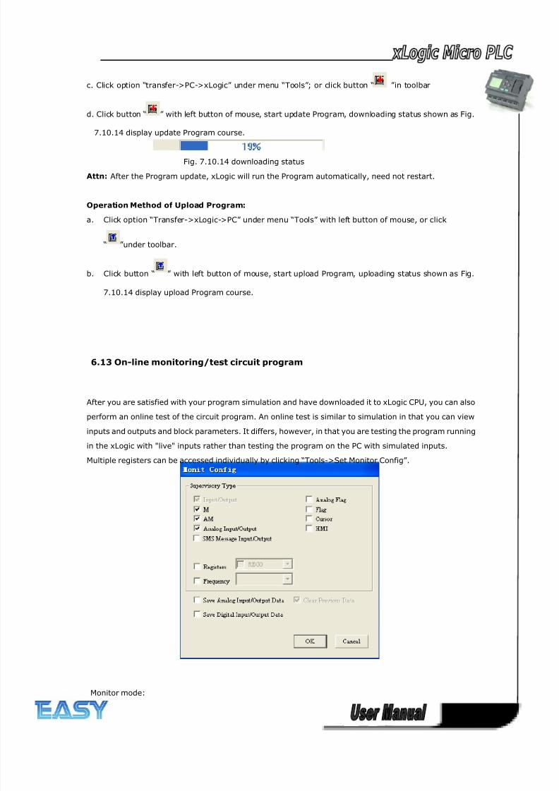
8/20/2019 XLogic User's Manual2
http://slidepdf.com/reader/full/xlogic-users-manual2 260/338
260
c. Click option “transfer->PC->xLogic” under menu “Tools”; or click button “ ”in toolbar
d. Click button “ ” with left button of mouse, start update Program, downloading status shown as Fig.
7.10.14 display update Program course.
Fig. 7.10.14 downloading status
Attn: After the Program update, xLogic will run the Program automatically, need not restart.
Operation Method of Upload Program:
a. Click option “Transfer->xLogic->PC” under menu “Tools” with left button of mouse, or click
“ ”under toolbar.
b. Click button “ ” with left button of mouse, start upload Program, uploading status shown as Fig.
7.10.14 display upload Program course.
6.13 On-line monitoring/test circuit program
After you are satisfied with your program simulation and have downloaded it to xLogic CPU, you can also
perform an online test of the circuit program. An online test is similar to simulation in that you can view
inputs and outputs and block parameters. It differs, however, in that you are testing the program running
in the xLogic with "live" inputs rather than testing the program on the PC with simulated inputs.
Multiple registers can be accessed individually by clicking “Tools->Set Monitor Config”.
Monitor mode:
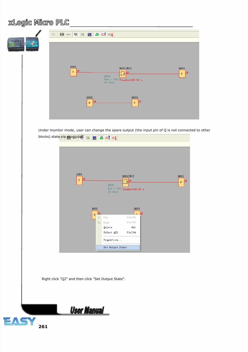
8/20/2019 XLogic User's Manual2
http://slidepdf.com/reader/full/xlogic-users-manual2 261/338
261
Under monitor mode, user can change the spare output (the input pin of Q is not connected to other
blocks) state via xLogicsoft.
Right click "Q2" and then click "Set Output State".
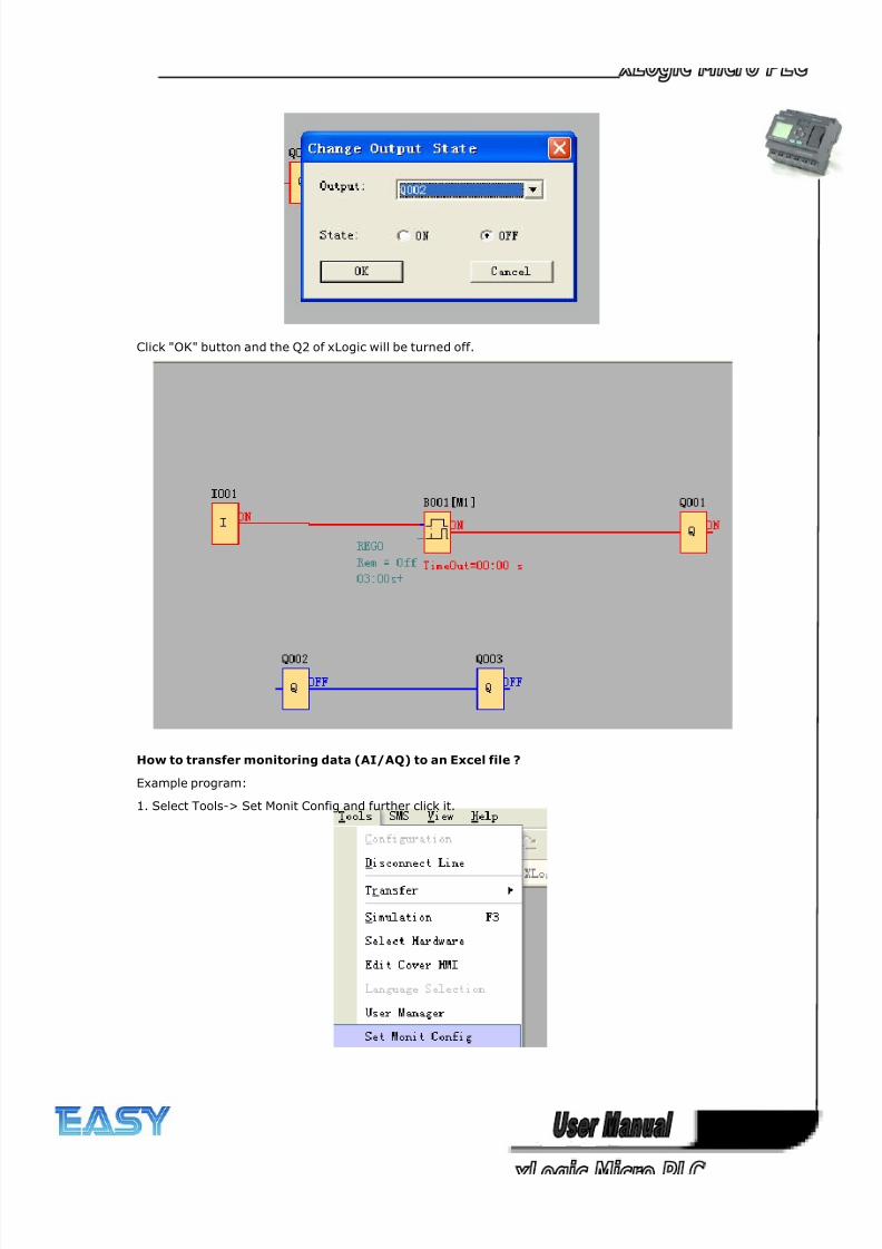
8/20/2019 XLogic User's Manual2
http://slidepdf.com/reader/full/xlogic-users-manual2 262/338
262
Click "OK" button and the Q2 of xLogic will be turned off.
How to transfer monitoring data (AI/AQ) to an Excel file ?
Example program:
1. Select Tools-> Set Monit Config and further click it.
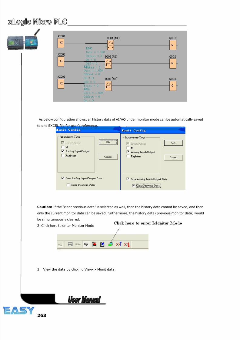
8/20/2019 XLogic User's Manual2
http://slidepdf.com/reader/full/xlogic-users-manual2 263/338
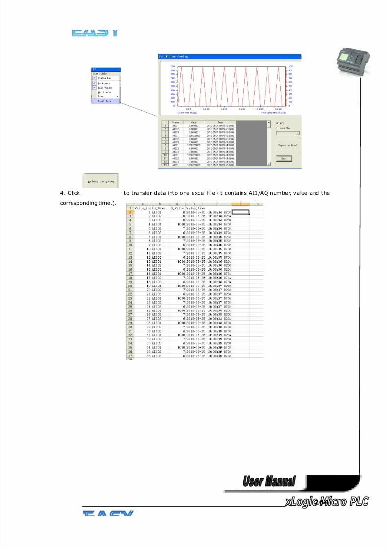
8/20/2019 XLogic User's Manual2
http://slidepdf.com/reader/full/xlogic-users-manual2 264/338
264
4. Click to transfer data into one excel file (it contains AI1/AQ number, value and the
corresponding time.).
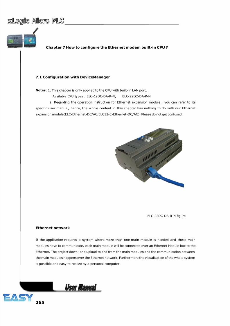
8/20/2019 XLogic User's Manual2
http://slidepdf.com/reader/full/xlogic-users-manual2 265/338
265
Chapter 7 How to configure the Ethernet modem built-in CPU ?
7.1 Configuration with DeviceManager
Notes: 1. This chapter is only applied to the CPU with built-in LAN port.
Available CPU types : ELC-12DC-DA-R-N; ELC-22DC-DA-R-N
2. Regarding the operation instruction for Ethernet expansion module , you can refer to its
specific user manual, hence, the whole content in this chapter has nothing to do with our Ethernet
expansion module(ELC-Ethernet-DC/AC,ELC12-E-Ethernet-DC/AC). Please do not get confused.
ELC-22DC-DA-R-N figure
Ethernet network
If the application requires a system where more than one main module is needed and these main
modules have to communicate, each main module will be connected over an Ethernet Module box to the
Ethernet. The project down- and upload to and from the main modules and the communication between
the main modules happens over the Ethernet network. Furthermore the visualization of the whole system
is possible and easy to realize by a personal computer.
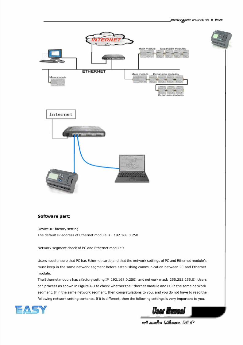
8/20/2019 XLogic User's Manual2
http://slidepdf.com/reader/full/xlogic-users-manual2 266/338
266
Software part:
Device IP factory setting
The default IP address of Ethernet module is:192.168.0.250
Network segment check of PC and Ethernet module’s
Users need ensure that PC has Ethernet cards,and that the network settings of PC and Ethernet module’s
must keep in the same network segment before establishing communication between PC and Ethernet
module.
The Ethernet module has a factory setting IP(192.168.0.250)and network mask(255.255.255.0). Users
can process as shown in Figure 4.3 to check whether the Ethernet module and PC in the same network
segment. If in the same network segment, then congratulations to you, and you do not have to read the
following network setting contents. If it is different, then the following settings is very important to you.
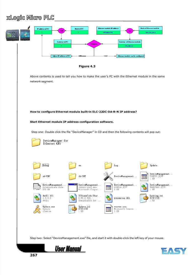
8/20/2019 XLogic User's Manual2
http://slidepdf.com/reader/full/xlogic-users-manual2 267/338
267
Figure 4.3
Above contents is used to tell you how to make the user’s PC with the Ethernet module in the same
network segment.
How to configure Ethernet module built-in ELC-22DC-DA-R-N IP address?
Start Ethernet module IP address configuration software.
Step one: Double click the file “DeviceManager” in CD and then the following contents will pop out:
Step two: Select “DeviceManagement.exe” file, and start it with double-click the left key of your mouse.
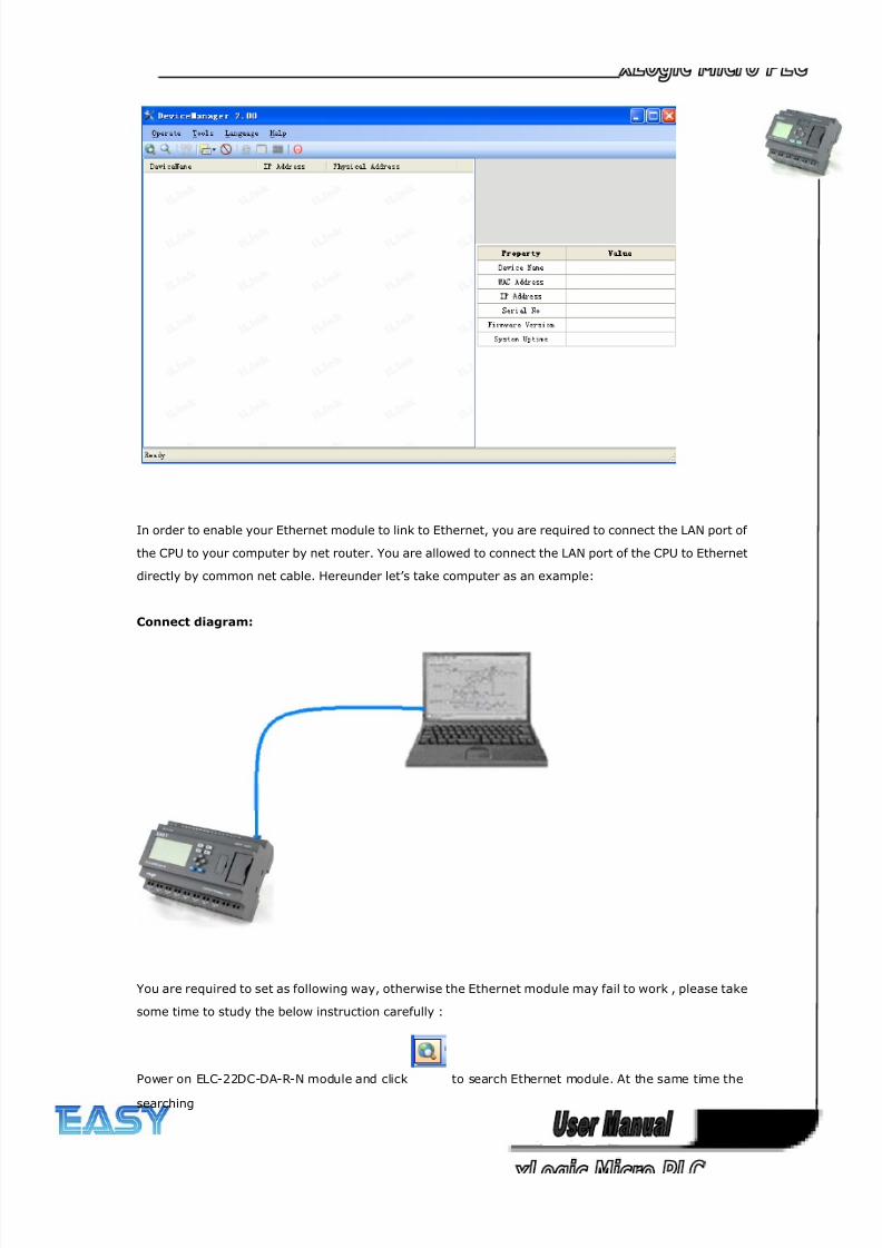
8/20/2019 XLogic User's Manual2
http://slidepdf.com/reader/full/xlogic-users-manual2 268/338
268
In order to enable your Ethernet module to link to Ethernet, you are required to connect the LAN port of
the CPU to your computer by net router. You are allowed to connect the LAN port of the CPU to Ethernet
directly by common net cable. Hereunder let’s take computer as an example:
Connect diagram:
You are required to set as following way, otherwise the Ethernet module may fail to work , please take
some time to study the below instruction carefully :
Power on ELC-22DC-DA-R-N module and click to search Ethernet module. At the same time the
searching
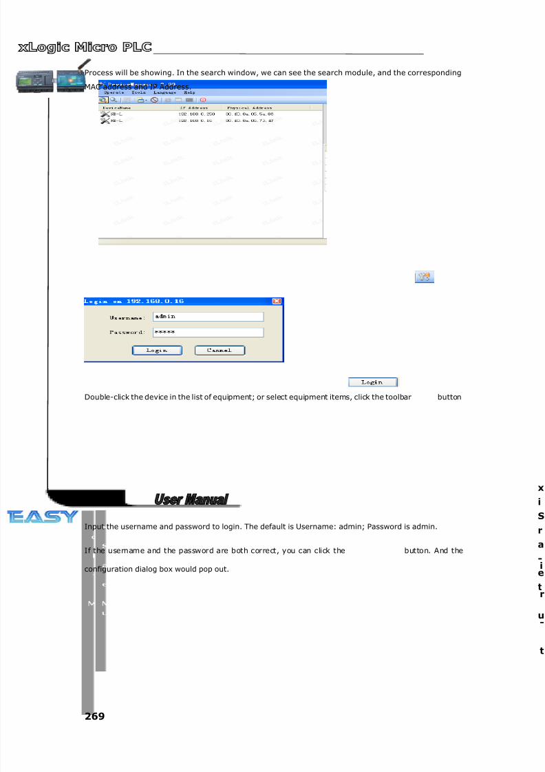
8/20/2019 XLogic User's Manual2
http://slidepdf.com/reader/full/xlogic-users-manual2 269/338
269
Process will be showing. In the search window, we can see the search module, and the corresponding
MAC address and IP Address.
Double-click the device in the list of equipment; or select equipment items, click the toolbar button
Input the username and password to login. The default is Username: admin; Password is admin.
If the username and the password are both correct, you can click the button. And the
configuration dialog box would pop out. i
r
-
t
x
i
S
r
a
-
e
t
u
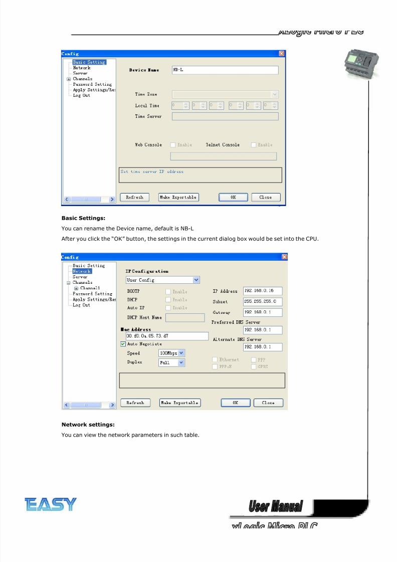
8/20/2019 XLogic User's Manual2
http://slidepdf.com/reader/full/xlogic-users-manual2 270/338
270
Basic Settings:
You can rename the Device name, default is NB-L
After you click the “OK” button, the settings in the current dialog box would be set into the CPU.
Network settings:
You can view the network parameters in such table.
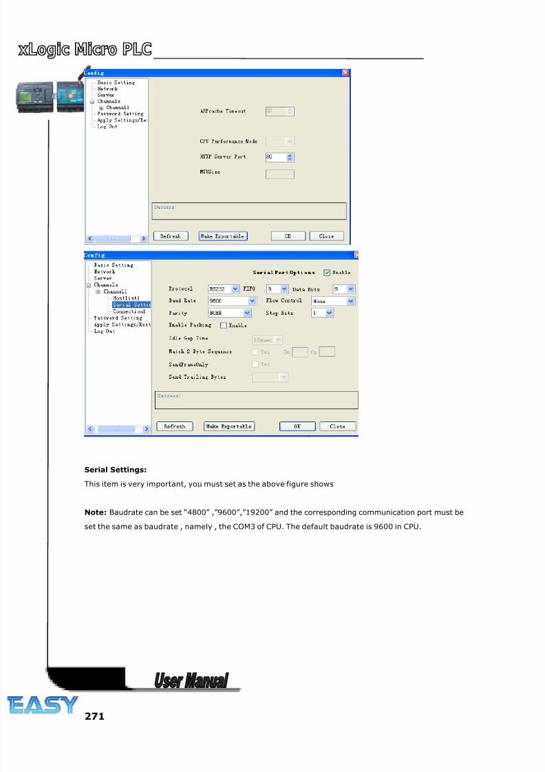
8/20/2019 XLogic User's Manual2
http://slidepdf.com/reader/full/xlogic-users-manual2 271/338
271
Serial Settings:
This item is very important, you must set as the above figure shows
Note: Baudrate can be set “4800” ,”9600”,”19200” and the corresponding communication port must be
set the same as baudrate , namely , the COM3 of CPU. The default baudrate is 9600 in CPU.
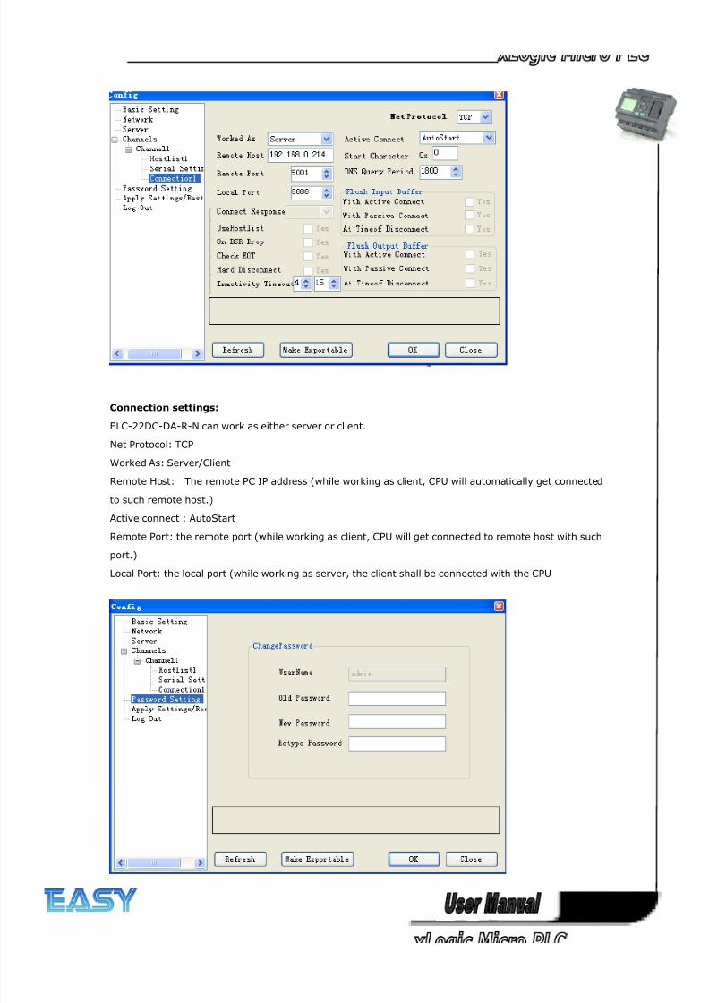
8/20/2019 XLogic User's Manual2
http://slidepdf.com/reader/full/xlogic-users-manual2 272/338
272
Connection settings:
ELC-22DC-DA-R-N can work as either server or client.
Net Protocol: TCP
Worked As: Server/Client
Remote Host: The remote PC IP address (while working as client, CPU will automatically get connected
to such remote host.)
Active connect : AutoStart
Remote Port: the remote port (while working as client, CPU will get connected to remote host with such
port.)
Local Port: the local port (while working as server, the client shall be connected with the CPU
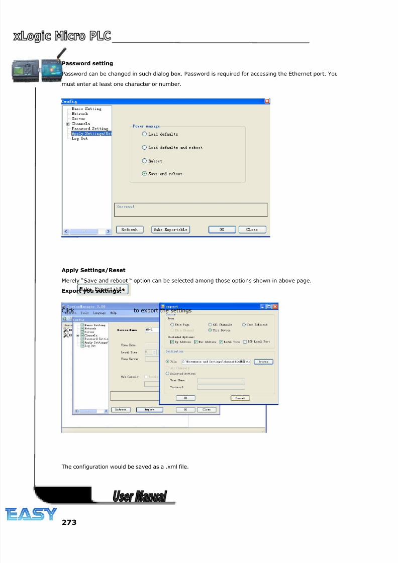
8/20/2019 XLogic User's Manual2
http://slidepdf.com/reader/full/xlogic-users-manual2 273/338
273
Password setting
Password can be changed in such dialog box. Password is required for accessing the Ethernet port. You
must enter at least one character or number.
Apply Settings/Reset
Merely “Save and reboot “ option can be selected among those options shown in above page.
Export you settings:
Click to export the settings
The configuration would be saved as a .xml file.
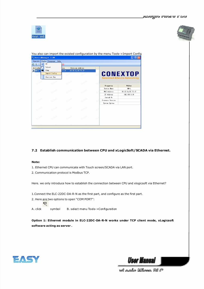
8/20/2019 XLogic User's Manual2
http://slidepdf.com/reader/full/xlogic-users-manual2 274/338
274
You also can import the existed configuration by the menu Tools->Import Config
7.2 Establish communication between CPU and xLogicSoft/SCADA via Ethernet.
Note:
1. Ethernet CPU can communicate with Touch screen/SCADA via LAN port.
2. Communication protocol is Modbus TCP.
Here. we only introduce how to establish the connection between CPU and xlogicsoft via Ethernet?
1.Connect the ELC-22DC-DA-R-N as the first part, and configure as the first part.
2. Here are two options to open “COM PORT”:
A. click symbol B. select menu Tools->Configuration
Option 1: Ethernet module in ELC-22DC-DA-R-N works under TCP client mode, xLogicsoft
software acting as server .
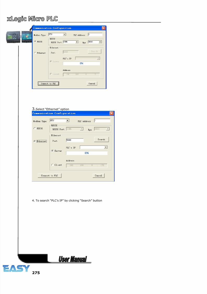
8/20/2019 XLogic User's Manual2
http://slidepdf.com/reader/full/xlogic-users-manual2 275/338
275
3.Select “Ethernet” option
4. To search “PLC’s IP” by clicking “Search” button
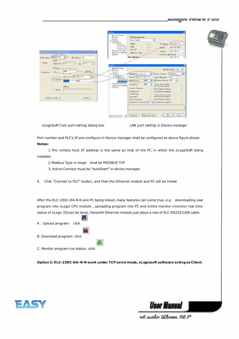
8/20/2019 XLogic User's Manual2
http://slidepdf.com/reader/full/xlogic-users-manual2 276/338
276
xLogicSoft Com port setting dialog box LAN port setting in Device manager
Port number and PLC’s IP pre-configure in Device manager shall be configured as above figure shows
Notes:
1.The remote host IP address is the same as that of the PC in which the xLogicSoft being
installed .
2.Modbus Type in xlogic shall be MODBUS TCP
3. Active Connect must be “AutoStart” in device manager.
5. Click "Connect to PLC" button, and then the Ethernet module and PC will be linked.
After the ELC-22DC-DA-R-N and PC being linked, many features can come true, e.g. downloading user
program into xLogic CPU module , uploading program into PC and online monitor (monitor real time
status of xLogic IO)can be done, herewith Ethernet module just plays a role of ELC-RS232/USB cable.
A . Upload program: click
B. Download program: click
C. Monitor program run status: click
Option 2: ELC-22DC-DA-R-N work under TCP serve mode, xLogicsoft software acting as Client.
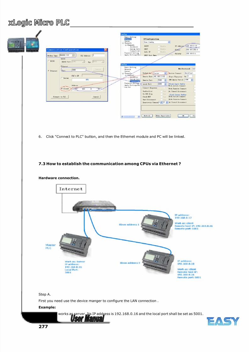
8/20/2019 XLogic User's Manual2
http://slidepdf.com/reader/full/xlogic-users-manual2 277/338
277
6. Click "Connect to PLC" button, and then the Ethernet module and PC will be linked.
7.3 How to establish the communication among CPUs via Ethernet ?
Hardware connection.
Step A.
First you need use the device manger to configure the LAN connection .
Example:
Master PLC works as server. Its IP address is 192.168.0.16 and the local port shall be set as 5001.
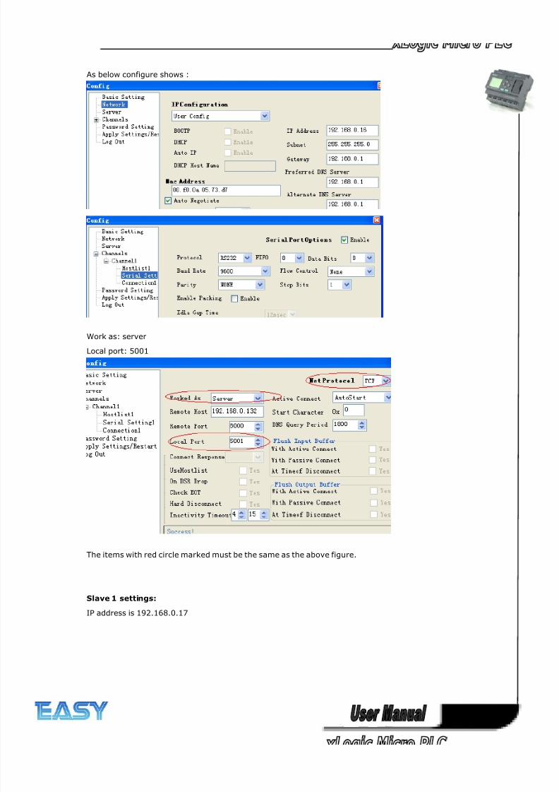
8/20/2019 XLogic User's Manual2
http://slidepdf.com/reader/full/xlogic-users-manual2 278/338
278
As below configure shows :
Work as: server
Local port: 5001
The items with red circle marked must be the same as the above figure.
Slave 1 settings:
IP address is 192.168.0.17
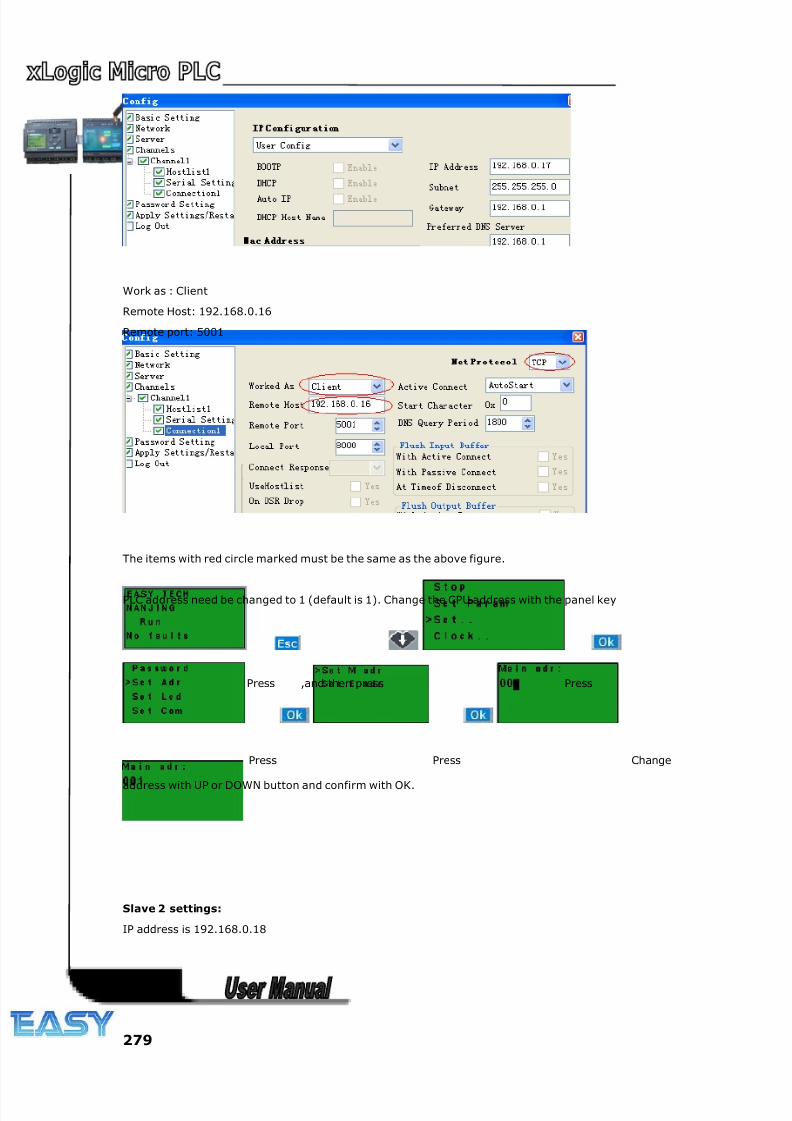
8/20/2019 XLogic User's Manual2
http://slidepdf.com/reader/full/xlogic-users-manual2 279/338
279
Work as : Client
Remote Host: 192.168.0.16
Remote port: 5001
The items with red circle marked must be the same as the above figure.
PLC address need be changed to 1 (default is 1). Change the CPU address with the panel key
Press ,and then press Press
Press Press Change
address with UP or DOWN button and confirm with OK.
Slave 2 settings:
IP address is 192.168.0.18
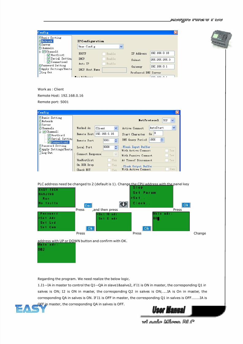
8/20/2019 XLogic User's Manual2
http://slidepdf.com/reader/full/xlogic-users-manual2 280/338
280
Work as : Client
Remote Host: 192.168.0.16
Remote port: 5001
PLC address need be changed to 2 (default is 1). Change the CPU address with the panel key
Press ,and then press Press
Press Press Change
address with UP or DOWN button and confirm with OK.
Regarding the program. We need realize the below logic.
1.I1--IA in master to control the Q1--QA in slave1&salve2, if I1 is ON in master, the corresponding Q1 in
salves is ON; I2 is ON in master, the corresponding Q2 in salves is ON;....IA is On in master, the
corresponding QA in salves is ON. If I1 is OFF in master, the corresponding Q1 in salves is OFF.......IA is
OFF in master, the corresponding QA in salves is OFF.
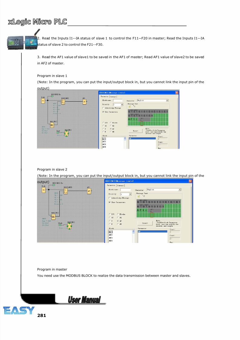
8/20/2019 XLogic User's Manual2
http://slidepdf.com/reader/full/xlogic-users-manual2 281/338
281
2. Read the Inputs I1--IA status of slave 1 to control the F11--F20 in master; Read the Inputs I1--IA
status of slave 2 to control the F21--F30.
3. Read the AF1 value of slave1 to be saved in the AF1 of master; Read AF1 value of slave2 to be saved
in AF2 of master.
Program in slave 1
(Note: In the program, you can put the input/output block in, but you cannot link the input pin of the
output)
Program in slave 2
(Note: In the program, you can put the input/output block in, but you cannot link the input pin of the
output)
Program in master
You need use the MODBUS BLOCK to realize the data transmission between master and slaves.
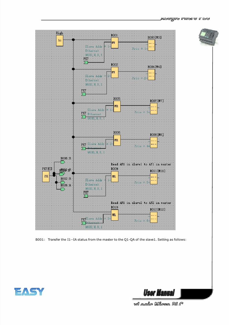
8/20/2019 XLogic User's Manual2
http://slidepdf.com/reader/full/xlogic-users-manual2 282/338
282
B001: Transfer the I1--IA status from the master to the Q1-QA of the slave1. Setting as follows:
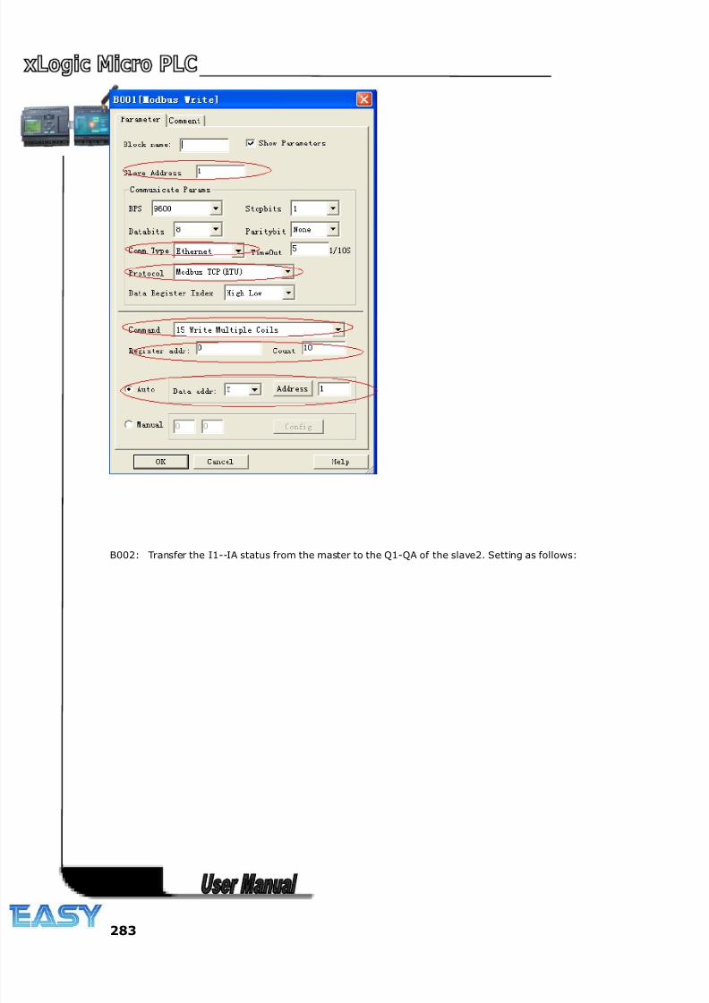
8/20/2019 XLogic User's Manual2
http://slidepdf.com/reader/full/xlogic-users-manual2 283/338
283
B002: Transfer the I1--IA status from the master to the Q1-QA of the slave2. Setting as follows:
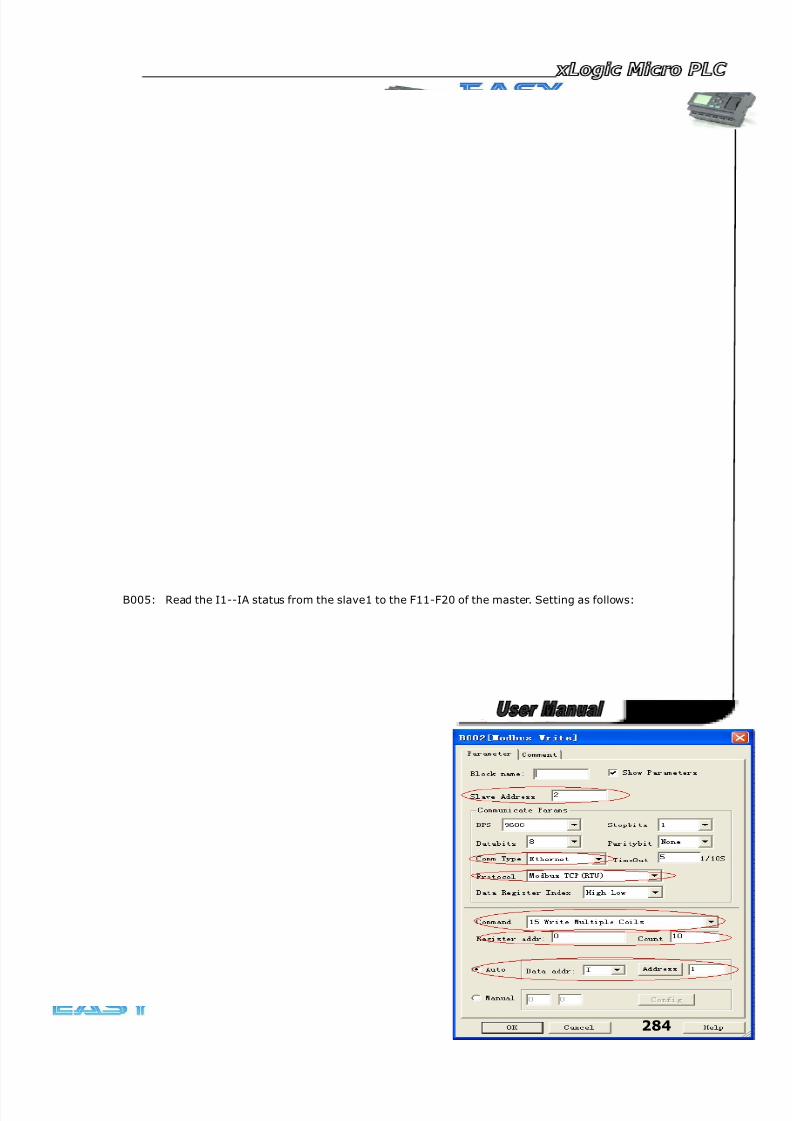
8/20/2019 XLogic User's Manual2
http://slidepdf.com/reader/full/xlogic-users-manual2 284/338
284
B005: Read the I1--IA status from the slave1 to the F11-F20 of the master. Setting as follows:
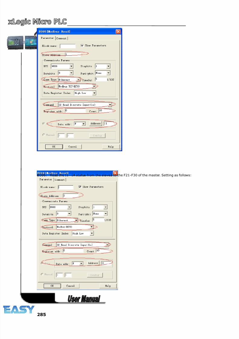
8/20/2019 XLogic User's Manual2
http://slidepdf.com/reader/full/xlogic-users-manual2 285/338
285
B006: Read the I1--IA status from the slave2 to the F21-F30 of the master. Setting as follows:
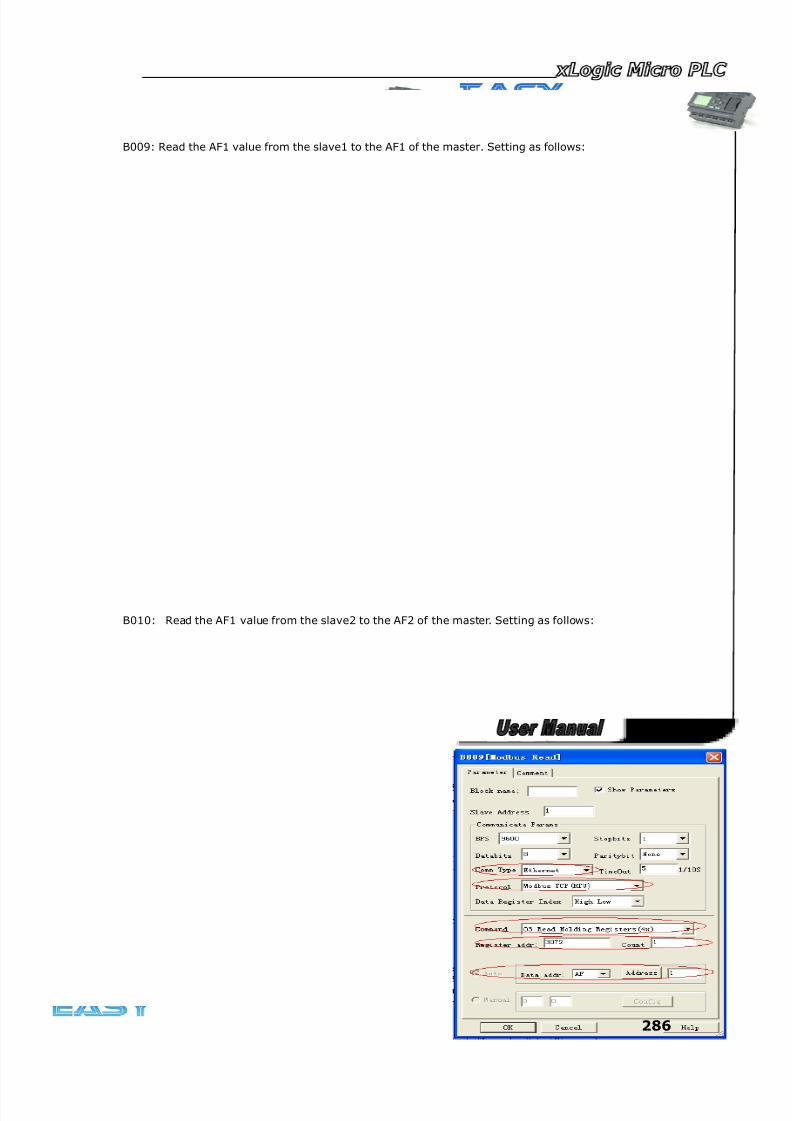
8/20/2019 XLogic User's Manual2
http://slidepdf.com/reader/full/xlogic-users-manual2 286/338
286
B009: Read the AF1 value from the slave1 to the AF1 of the master. Setting as follows:
B010: Read the AF1 value from the slave2 to the AF2 of the master. Setting as follows:
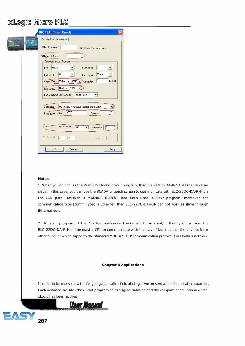
8/20/2019 XLogic User's Manual2
http://slidepdf.com/reader/full/xlogic-users-manual2 287/338
287
Notes:
1. When you do not use the MODBUS blocks in your program, then ELC-22DC-DA-R-N CPU shall work as
slave, in this case, you can use the SCADA or touch screen to communicate with ELC-22DC-DA-R-N via
the LAN port. However, if MODBUS BLOCKS had been used in your program, moreover, the
communication type (comm Type) is Ethernet, then ELC-22DC-DA-R-N can not work as slave through
Ethernet port
2. In your program, if the Modbus read/write blocks would be used, then you can use the
ELC-22DC-DA-R-N as the master CPU to communicate with the slave ( i.e. xlogic or the devices from
other supplier which supports the standard MODBUS TCP communication protocol.) in Modbus network
Chapter 8 Applications
In order to let users know the far going application field of xLogic, we present a set of application example.
Each instance includes the circuit program of its original solution and the compare of solution in which
xLogic has been applied.
You can find the following solution:
8/20/2019 XLogic User's Manual2
http://slidepdf.com/reader/full/xlogic-users-manual2 288/338
288
Dual-function switch
Automatic gate
Ventilation system
Industry door
Daylight lamps
Rain water pump
Note:
The application example of xLogic is available free of charge to our clients, but we can’t make any
promise, it is only to explain the general rule of using xLogic. It is possible that these instances can be
different from user’s specific application, so user should take all related responsibility of running those
instance systems, and we sincerely suggest user shall refer to relevant nation standard and installation
rules related to systems. Also, we have to point out that error is unavoidable, and we reserve the
according modification rights.
8.1 Dual-function switch
Requirements for stairway lighting systems
The basic requirements for a stairway lighting system are as follows:
When someone is using the stairs, the stairway lights should be on.
If no one is in the stairway, the lights should go out in order to save energy.
8.1.1 Standard solution
Up to now two methods were known to control such a lighting system:
Pulse relay: When the lights are off, press any of the pushbuttons to switch on the lights. When the
lights are on, press any of the pushbuttons to switch off the lights again.
Disadvantage: People often forget to switch off the lights
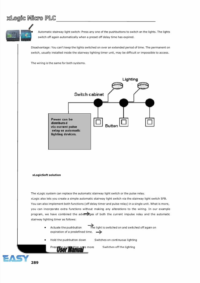
8/20/2019 XLogic User's Manual2
http://slidepdf.com/reader/full/xlogic-users-manual2 289/338
289
Automatic stairway light switch: Press any one of the pushbuttons to switch on the lights. The lights
switch off again automatically when a preset off delay time has expired.
Disadvantage: You can't keep the lights switched on over an extended period of time. The permanent on
switch, usually installed inside the stairway lighting timer unit, may be difficult or impossible to access.
The wiring is the same for both systems.
xLogicSoft solution
The xLogic system can replace the automatic stairway light switch or the pulse relay.
xLogic also lets you create a simple automatic stairway light switch via the stairway light switch SFB.
You can also implement both functions (off delay timer and pulse relay) in a single unit. What is more,
you can incorporate extra functions without making any alterations to the wiring. In our example
program, we have combined the advantages of both the current impulse relay and the automatic
stairway lighting timer as follows:
• Actuate the pushbutton The light is switched on and switched off again on
expiration of a predefined time.
• Hold the pushbutton down Switches on continuous lighting
• Press the pushbutton once more Switches off the lighting

8/20/2019 XLogic User's Manual2
http://slidepdf.com/reader/full/xlogic-users-manual2 290/338
290
8.1.2 The scheme of xLogic
The wiring of a lighting system with xLogic is the same as standard corridor or stairway lighting systems.
Only the automatic lighting timer/pulse relay is replaced.
xLogic lets you quickly and easily combine all those functions in a single dual-function switch SFB,
without additional wiring and expenditure.
Apply pulse relay of xLogic
When the input “I1” has a pulse, the output “Q1”will be on or off.
Automatic stairway lighting system
If input “I1”has a pulse, the output Q1will be on and keep 6 minutes, then be off.
Apply xLogic to realize multiple switches
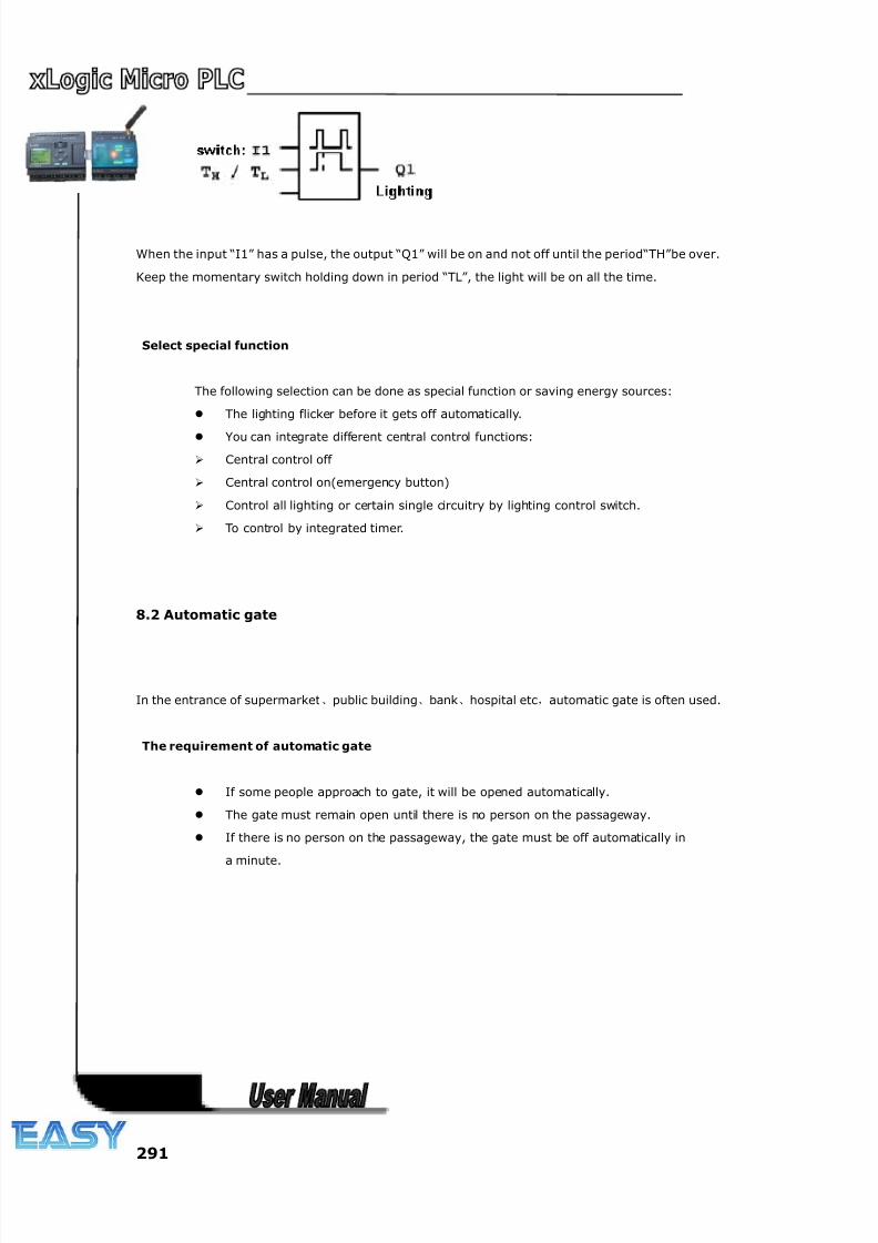
8/20/2019 XLogic User's Manual2
http://slidepdf.com/reader/full/xlogic-users-manual2 291/338
291
When the input “I1” has a pulse, the output “Q1” will be on and not off until the period“TH”be over.
Keep the momentary switch holding down in period “TL”, the light will be on all the time.
Select special function
The following selection can be done as special function or saving energy sources:
The lighting flicker before it gets off automatically.
You can integrate different central control functions:
Central control off
Central control on(emergency button)
Control all lighting or certain single circuitry by lighting control switch.
To control by integrated timer.
8.2 Automatic gate
In the entrance of supermarket、public building、bank、hospital etc,automatic gate is often used.
The requirement of automatic gate
If some people approach to gate, it will be opened automatically.
The gate must remain open until there is no person on the passageway.
If there is no person on the passageway, the gate must be off automatically in
a minute.
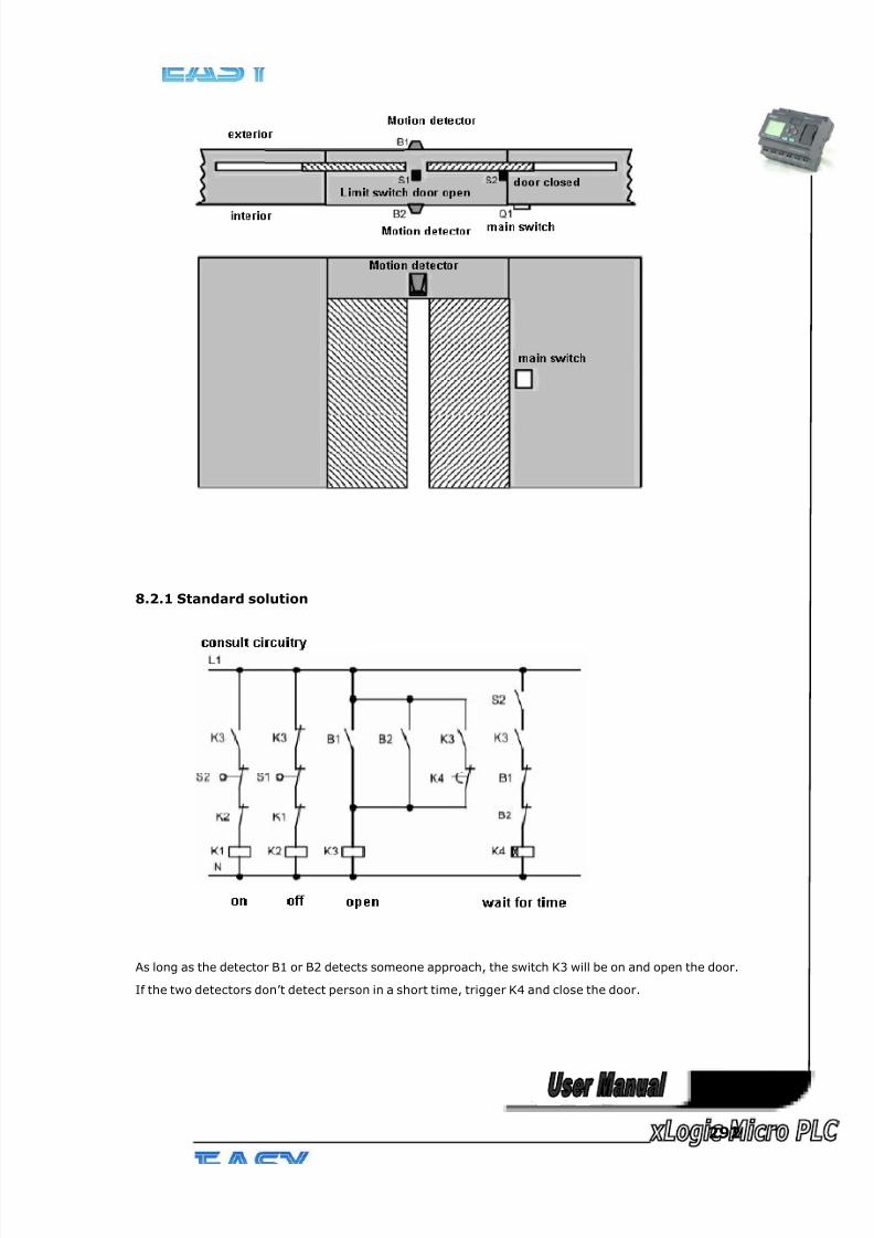
8/20/2019 XLogic User's Manual2
http://slidepdf.com/reader/full/xlogic-users-manual2 292/338
292
8.2.1 Standard solution
As long as the detector B1 or B2 detects someone approach, the switch K3 will be on and open the door.
If the two detectors don’t detect person in a short time, trigger K4 and close the door.
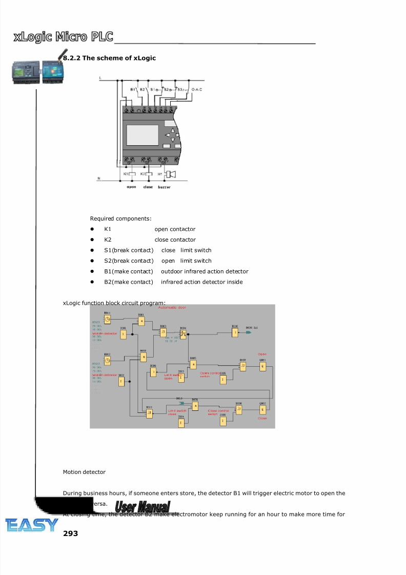
8/20/2019 XLogic User's Manual2
http://slidepdf.com/reader/full/xlogic-users-manual2 293/338
293
8.2.2 The scheme of xLogic
Required components:
K1 open contactor
K2 close contactor
S1(break contact) close limit switch
S2(break contact) open limit switch
B1(make contact) outdoor infrared action detector
B2(make contact) infrared action detector inside
xLogic function block circuit program:
Motion detector
During business hours, if someone enters store, the detector B1 will trigger electric motor to open the
door, vice versa.
At closing time, the detector B2 make electromotor keep running for an hour to make more time for
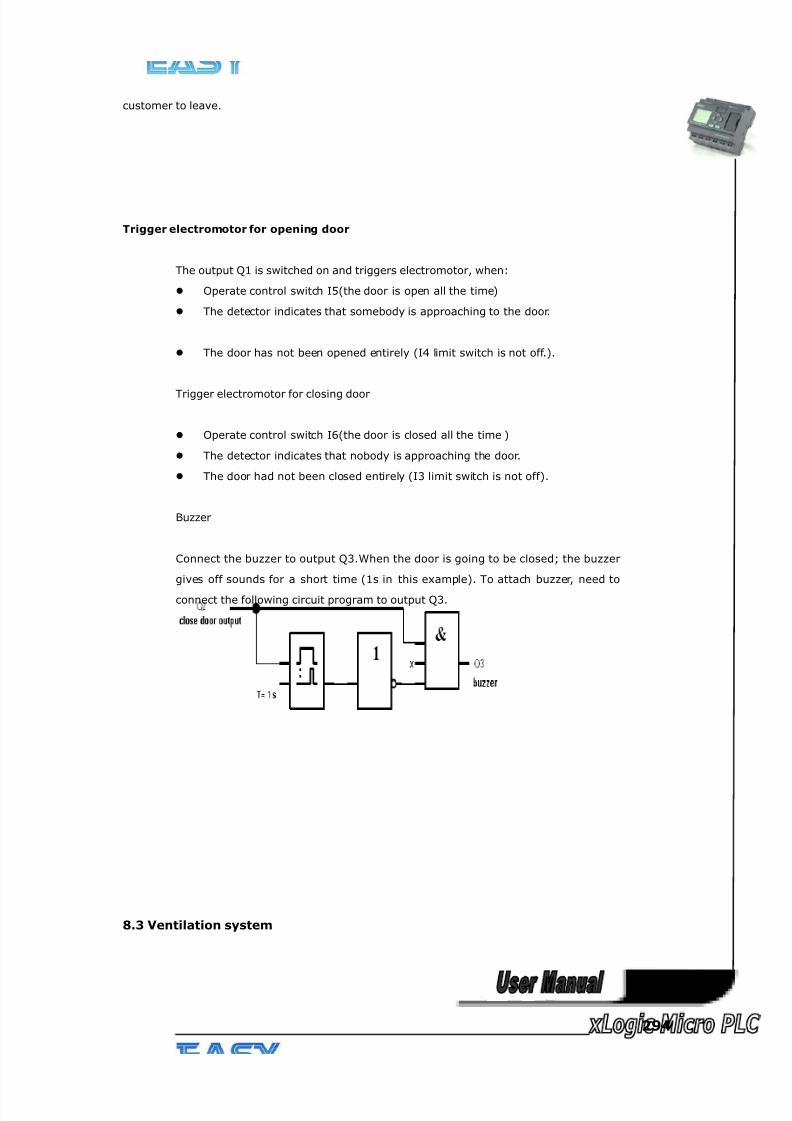
8/20/2019 XLogic User's Manual2
http://slidepdf.com/reader/full/xlogic-users-manual2 294/338
294
customer to leave.
Trigger electromotor for opening door
The output Q1 is switched on and triggers electromotor, when:
Operate control switch I5(the door is open all the time)
The detector indicates that somebody is approaching to the door.
The door has not been opened entirely (I4 limit switch is not off.).
Trigger electromotor for closing door
Operate control switch I6(the door is closed all the time )
The detector indicates that nobody is approaching the door.
The door had not been closed entirely (I3 limit switch is not off).
Buzzer
Connect the buzzer to output Q3.When the door is going to be closed; the buzzer
gives off sounds for a short time (1s in this example). To attach buzzer, need to
connect the following circuit program to output Q3.
8.3 Ventilation system
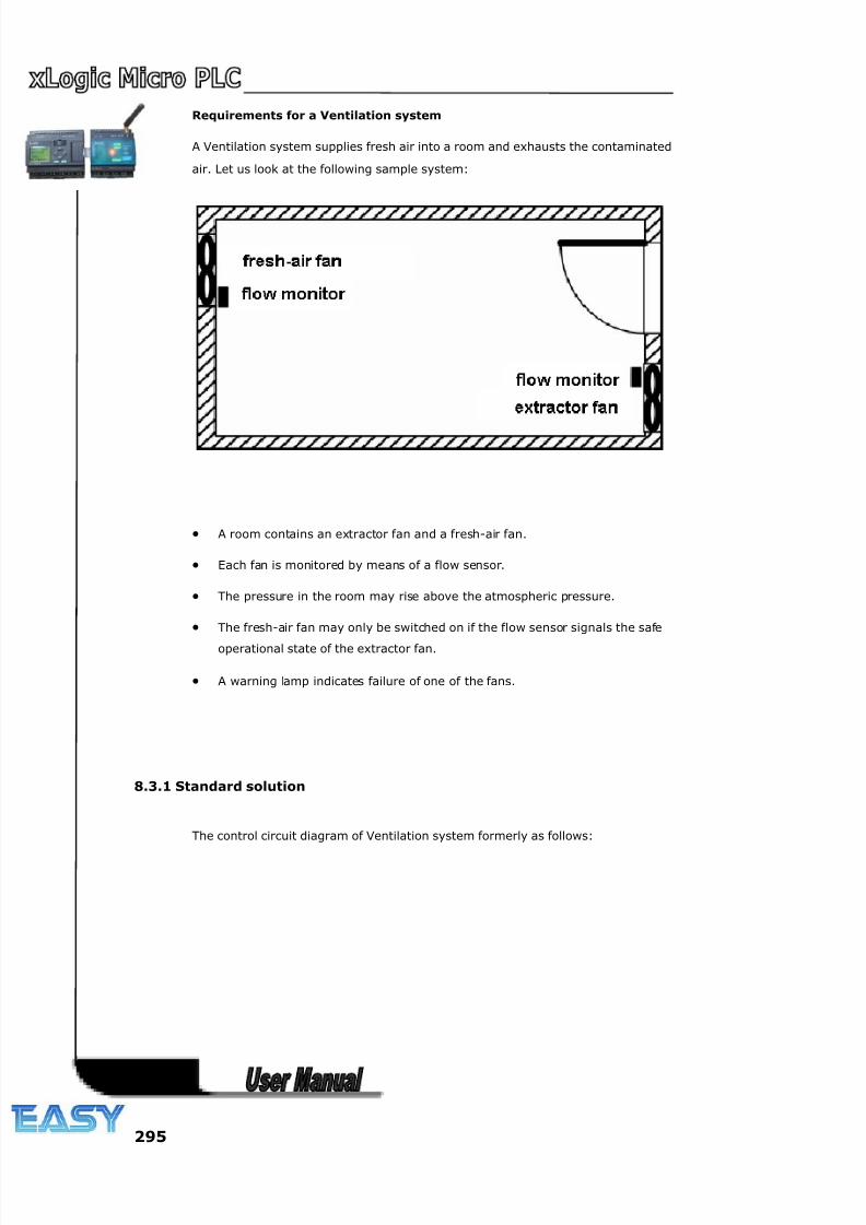
8/20/2019 XLogic User's Manual2
http://slidepdf.com/reader/full/xlogic-users-manual2 295/338
295
Requirements for a Ventilation system
A Ventilation system supplies fresh air into a room and exhausts the contaminated
air. Let us look at the following sample system:
• A room contains an extractor fan and a fresh-air fan.
• Each fan is monitored by means of a flow sensor.
• The pressure in the room may rise above the atmospheric pressure.
• The fresh-air fan may only be switched on if the flow sensor signals the safe
operational state of the extractor fan.
• A warning lamp indicates failure of one of the fans.
8.3.1 Standard solution
The control circuit diagram of Ventilation system formerly as follows:
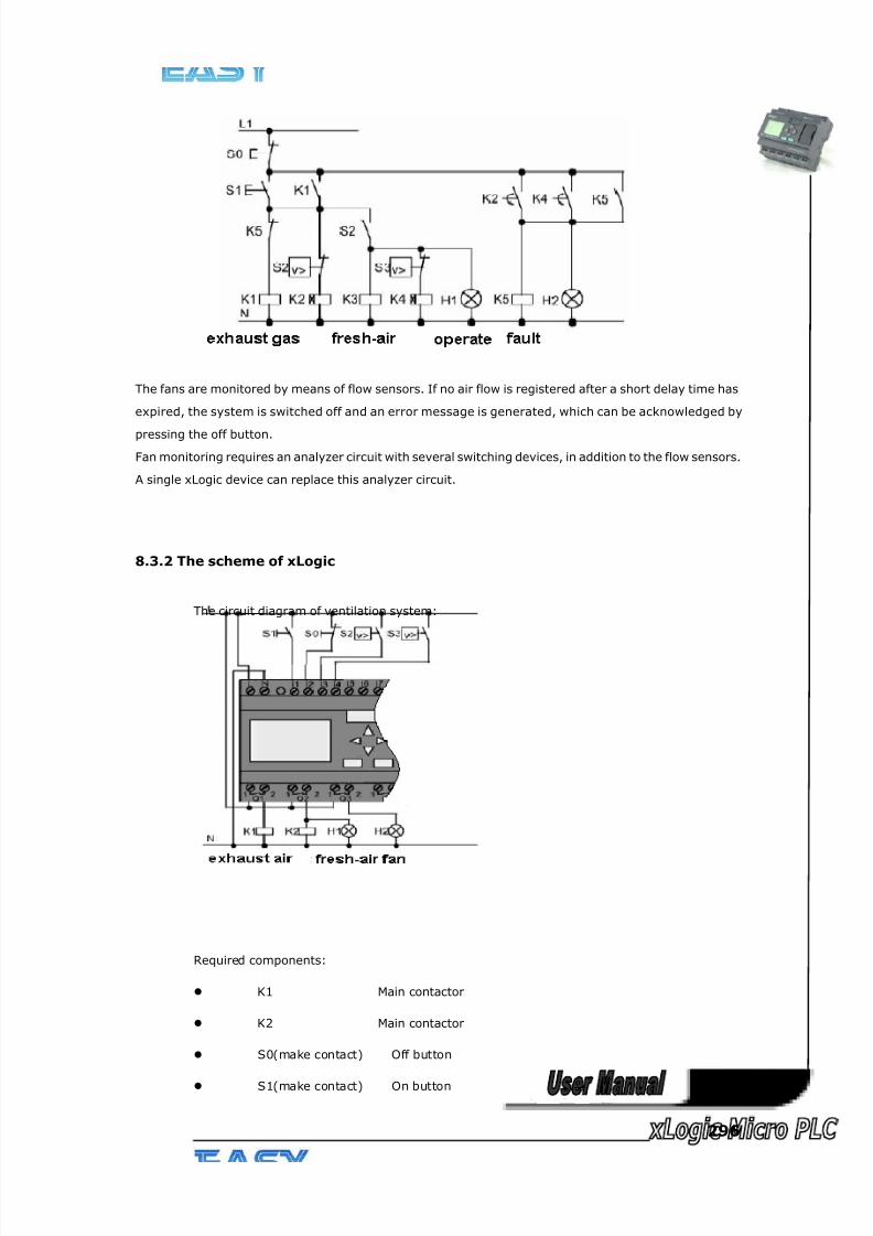
8/20/2019 XLogic User's Manual2
http://slidepdf.com/reader/full/xlogic-users-manual2 296/338
296
The fans are monitored by means of flow sensors. If no air flow is registered after a short delay time has
expired, the system is switched off and an error message is generated, which can be acknowledged by
pressing the off button.
Fan monitoring requires an analyzer circuit with several switching devices, in addition to the flow sensors.
A single xLogic device can replace this analyzer circuit.
8.3.2 The scheme of xLogic
The circuit diagram of ventilation system:
Required components:
K1 Main contactor
K2 Main contactor
S0(make contact) Off button
S1(make contact) On button
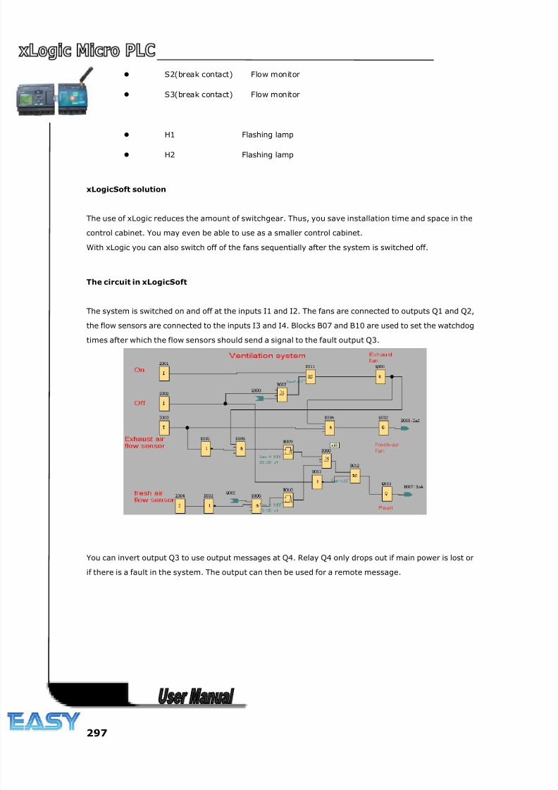
8/20/2019 XLogic User's Manual2
http://slidepdf.com/reader/full/xlogic-users-manual2 297/338
297
S2(break contact) Flow monitor
S3(break contact) Flow monitor
H1 Flashing lamp
H2 Flashing lamp
xLogicSoft solution
The use of xLogic reduces the amount of switchgear. Thus, you save installation time and space in the
control cabinet. You may even be able to use as a smaller control cabinet.
With xLogic you can also switch off of the fans sequentially after the system is switched off.
The circuit in xLogicSoft
The system is switched on and off at the inputs I1 and I2. The fans are connected to outputs Q1 and Q2,
the flow sensors are connected to the inputs I3 and I4. Blocks B07 and B10 are used to set the watchdog
times after which the flow sensors should send a signal to the fault output Q3.
You can invert output Q3 to use output messages at Q4. Relay Q4 only drops out if main power is lost or
if there is a fault in the system. The output can then be used for a remote message.
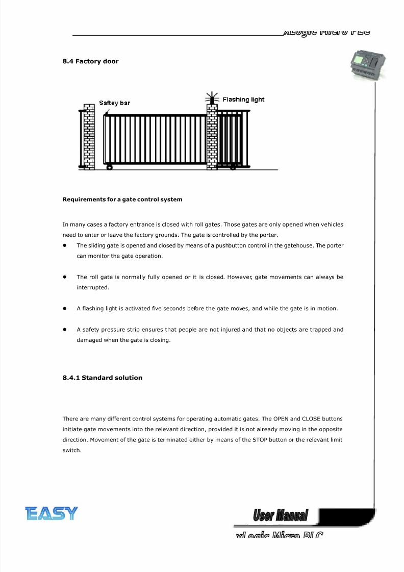
8/20/2019 XLogic User's Manual2
http://slidepdf.com/reader/full/xlogic-users-manual2 298/338
298
8.4 Factory door
Requirements for a gate control system
In many cases a factory entrance is closed with roll gates. Those gates are only opened when vehicles
need to enter or leave the factory grounds. The gate is controlled by the porter.
The sliding gate is opened and closed by means of a pushbutton control in the gatehouse. The porter
can monitor the gate operation.
The roll gate is normally fully opened or it is closed. However, gate movements can always be
interrupted.
A flashing light is activated five seconds before the gate moves, and while the gate is in motion.
A safety pressure strip ensures that people are not injured and that no objects are trapped and
damaged when the gate is closing.
8.4.1 Standard solution
There are many different control systems for operating automatic gates. The OPEN and CLOSE buttons
initiate gate movements into the relevant direction, provided it is not already moving in the opposite
direction. Movement of the gate is terminated either by means of the STOP button or the relevant limit
switch.
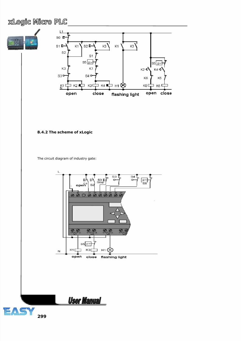
8/20/2019 XLogic User's Manual2
http://slidepdf.com/reader/full/xlogic-users-manual2 299/338
299
8.4.2 The scheme of xLogic
The circuit diagram of industry gate:
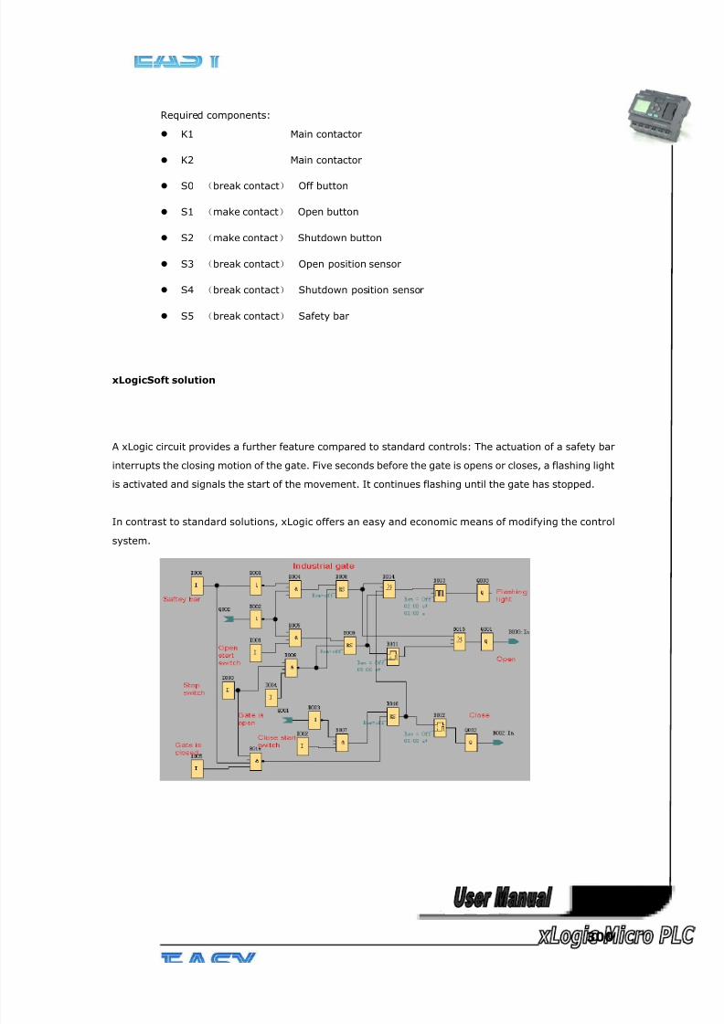
8/20/2019 XLogic User's Manual2
http://slidepdf.com/reader/full/xlogic-users-manual2 300/338
300
Required components:
K1 Main contactor
K2 Main contactor
S0 (break contact) Off button
S1 (make contact) Open button
S2 (make contact) Shutdown button
S3 (break contact) Open position sensor
S4 (break contact) Shutdown position sensor
S5 (break contact) Safety bar
xLogicSoft solution
A xLogic circuit provides a further feature compared to standard controls: The actuation of a safety bar
interrupts the closing motion of the gate. Five seconds before the gate is opens or closes, a flashing light
is activated and signals the start of the movement. It continues flashing until the gate has stopped.
In contrast to standard solutions, xLogic offers an easy and economic means of modifying the control
system.
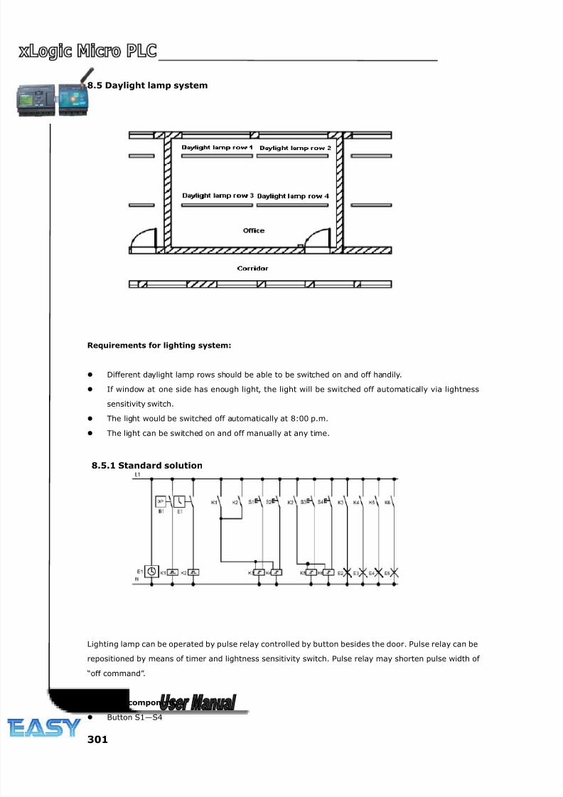
8/20/2019 XLogic User's Manual2
http://slidepdf.com/reader/full/xlogic-users-manual2 301/338
301
8.5 Daylight lamp system
Requirements for lighting system:
Different daylight lamp rows should be able to be switched on and off handily.
If window at one side has enough light, the light will be switched off automatically via lightness
sensitivity switch.
The light would be switched off automatically at 8:00 p.m.
The light can be switched on and off manually at any time.
8.5.1 Standard solution
Lighting lamp can be operated by pulse relay controlled by button besides the door. Pulse relay can be
repositioned by means of timer and lightness sensitivity switch. Pulse relay may shorten pulse width of
“off command”.
Required component:
Button S1—S4
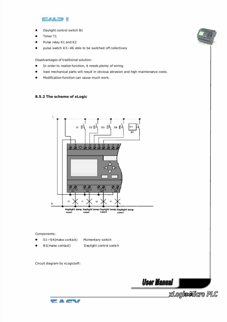
8/20/2019 XLogic User's Manual2
http://slidepdf.com/reader/full/xlogic-users-manual2 302/338
302
Daylight control switch B1
Timer T1
Pulse relay K1 and K2
pulse switch K3—K6 able to be switched off collectively
Disadvantages of traditional solution:
In order to realize function, it needs plenty of wiring.
Vast mechanical parts will result in obvious abrasion and high maintenance costs.
Modification function can cause much work.
8.5.2 The scheme of xLogic
Components:
S1—S4(make contact) Momentary switch
B1(make contact) Daylight control switch
Circuit diagram by xLogicsoft:
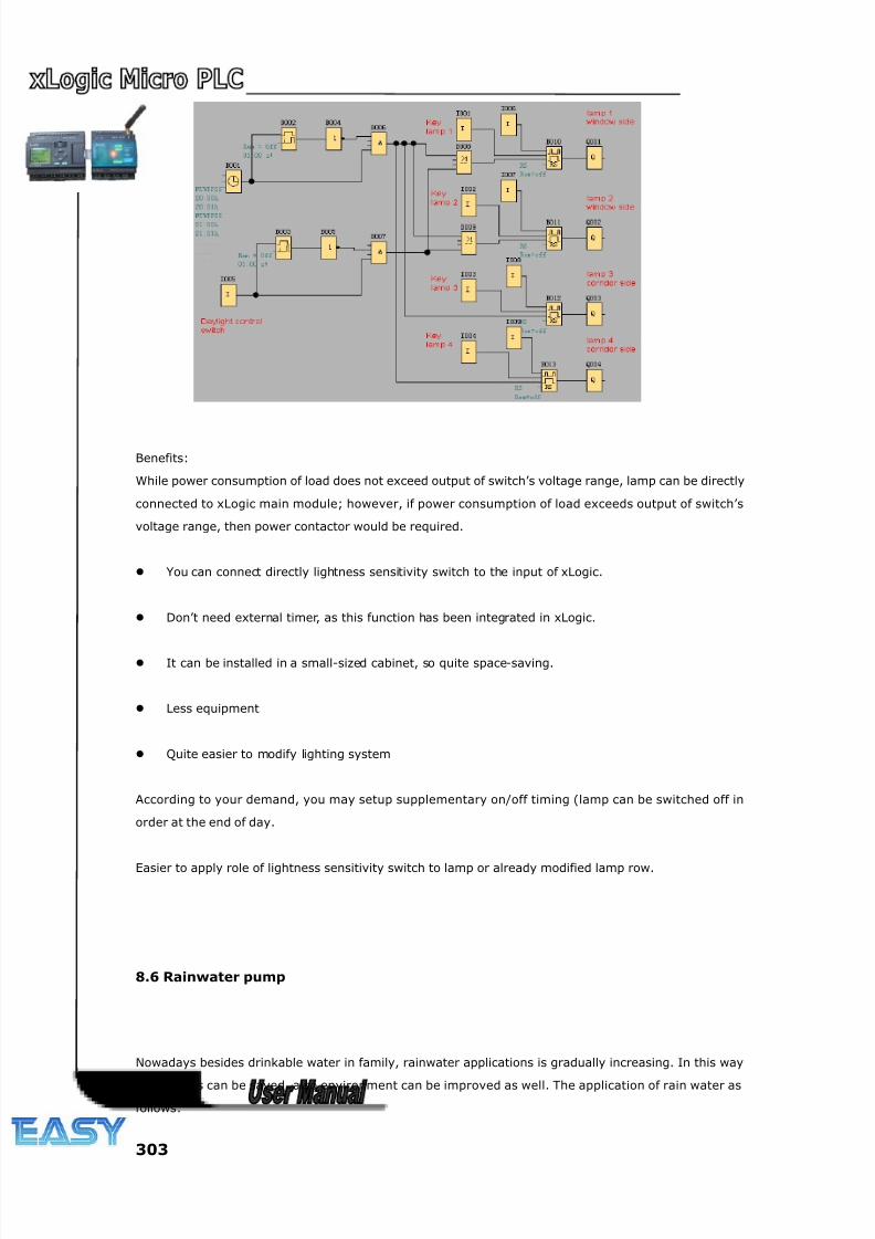
8/20/2019 XLogic User's Manual2
http://slidepdf.com/reader/full/xlogic-users-manual2 303/338
303
Benefits:
While power consumption of load does not exceed output of switch’s voltage range, lamp can be directly
connected to xLogic main module; however, if power consumption of load exceeds output of switch’s
voltage range, then power contactor would be required.
You can connect directly lightness sensitivity switch to the input of xLogic.
Don’t need external timer, as this function has been integrated in xLogic.
It can be installed in a small-sized cabinet, so quite space-saving.
Less equipment
Quite easier to modify lighting system
According to your demand, you may setup supplementary on/off timing (lamp can be switched off in
order at the end of day.
Easier to apply role of lightness sensitivity switch to lamp or already modified lamp row.
8.6 Rainwater pump
Nowadays besides drinkable water in family, rainwater applications is gradually increasing. In this way
much costs can be saved, also environment can be improved as well. The application of rain water as
follows:
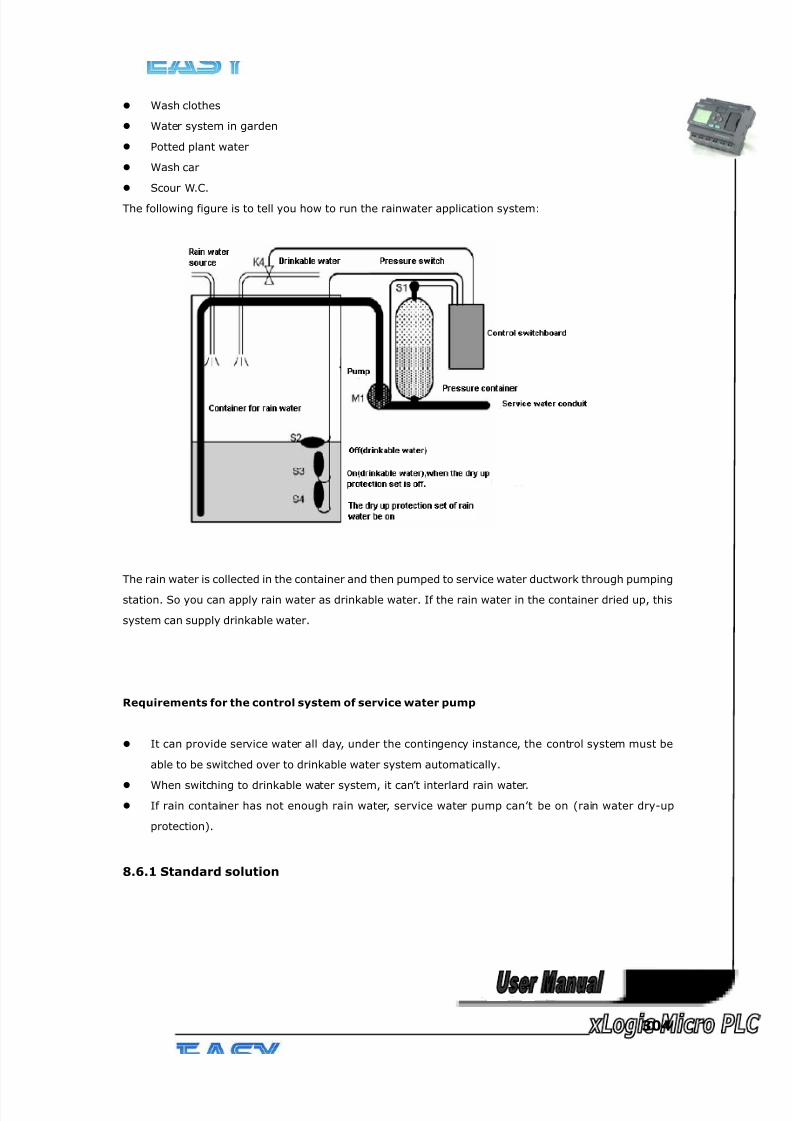
8/20/2019 XLogic User's Manual2
http://slidepdf.com/reader/full/xlogic-users-manual2 304/338
304
Wash clothes
Water system in garden
Potted plant water
Wash car
Scour W.C.
The following figure is to tell you how to run the rainwater application system:
The rain water is collected in the container and then pumped to service water ductwork through pumping
station. So you can apply rain water as drinkable water. If the rain water in the container dried up, this
system can supply drinkable water.
Requirements for the control system of service water pump
It can provide service water all day, under the contingency instance, the control system must be
able to be switched over to drinkable water system automatically.
When switching to drinkable water system, it can’t interlard rain water.
If rain container has not enough rain water, service water pump can’t be on (rain water dry-up
protection).
8.6.1 Standard solution
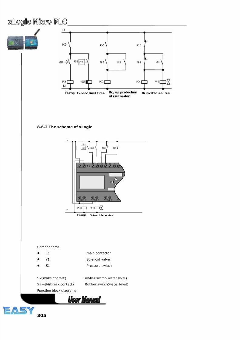
8/20/2019 XLogic User's Manual2
http://slidepdf.com/reader/full/xlogic-users-manual2 305/338
305
8.6.2 The scheme of xLogic
Components:
K1 main contactor
Y1 Solenoid valve
S1 Pressure switch
S2(make contact) Bobber switch(water level)
S3—S4(break contact) Bobber switch(water level)
Function block diagram:
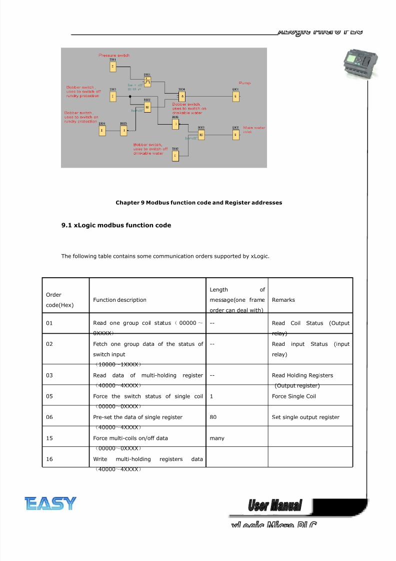
8/20/2019 XLogic User's Manual2
http://slidepdf.com/reader/full/xlogic-users-manual2 306/338
306
Chapter 9 Modbus function code and Register addresses
9.1 xLogic modbus function code
The following table contains some communication orders supported by xLogic.
Order
code(Hex)Function description
Length of
message(one frame
order can deal with)
Remarks
01 Read one group coil status( 00000~
0XXXX)
-- Read Coil Status (Output
relay)
02 Fetch one group data of the status of
switch input
(10000~1XXXX)
-- Read input Status (input
relay)
03 Read data of multi-holding register
(40000~4XXXX)
-- Read Holding Registers
(Output register)
05 Force the switch status of single coil
(00000~0XXXX)
1 Force Single Coil
06 Pre-set the data of single register
(40000~4XXXX)
80 Set single output register
15 Force multi-coils on/off data
(00000~0XXXX)
many
16 Write multi-holding registers data
(40000~4XXXX)
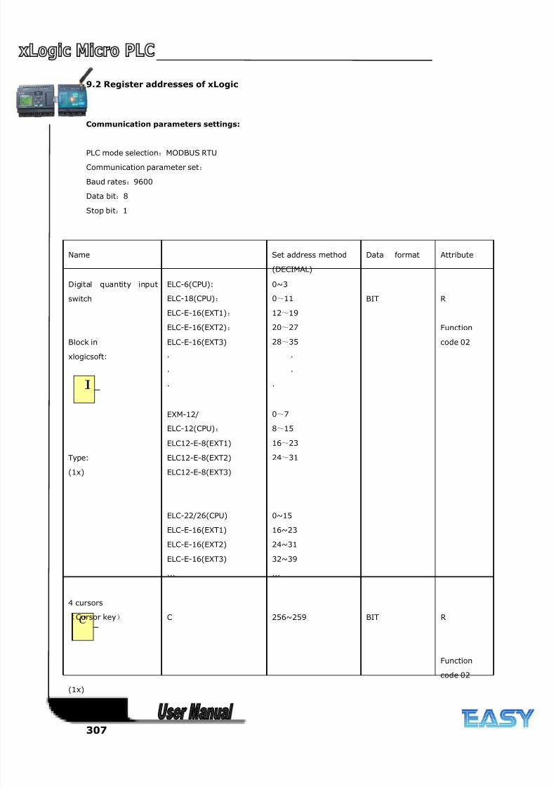
8/20/2019 XLogic User's Manual2
http://slidepdf.com/reader/full/xlogic-users-manual2 307/338
307
9.2 Register addresses of xLogic
Communication parameters settings:
PLC mode selection:MODBUS RTU
Communication parameter set:
Baud rates:9600
Data bit:8
Stop bit:1
Name Set address method
(DECIMAL)
Data format Attribute
Digital quantity input
switch
Block in
xlogicsoft:
Type:
(1x)
ELC-6(CPU):
ELC-18(CPU):
ELC-E-16(EXT1):
ELC-E-16(EXT2):
ELC-E-16(EXT3)
·
·
·
EXM-12/
ELC-12(CPU):
ELC12-E-8(EXT1)
ELC12-E-8(EXT2)
ELC12-E-8(EXT3)
ELC-22/26(CPU)
ELC-E-16(EXT1)
ELC-E-16(EXT2)
ELC-E-16(EXT3)
...
0~3
0~11
12~19
20~27
28~35
·
·
·
0~7
8~15
16~23
24~31
0~15
16~23
24~31
32~39
...
BIT R
Function
code 02
4 cursors
(Cursor key)
(1x)
C 256~259 BIT R
Function
code 02

8/20/2019 XLogic User's Manual2
http://slidepdf.com/reader/full/xlogic-users-manual2 308/338
308
Sms Input
(1x)
ELC-SMS-D-R
(SmsI1-SmsI6)
260~265 BIT R
Function
code 02
Sms Message Input
(1x)
ELC-SMS-D-R
(MsgI1-MsgI10) 266~275
BIT R
Function
code 02
Coils outputs
(0x)
ELC-6(CPU):
ELC-18(CPU):
ELC-E-16(EXT1):
ELC-E-16(EXT2):
ELC-E-16(EXT3):
·
·
·
EXM-12/ELC-12(CPU):
ELC12-E-8(EXT1)
ELC12-E-8(EXT2)
ELC12-E-8(EXT3)
ELC-22/26(CPU)
ELC-E-16(EXT1)
ELC-E-16(EXT2)
ELC-E-16(EXT3)
SMS Output
SMS Message Output
0~1
0~5
8~15
16~23
24~31
·
·
·
0~7
8~15
16~23
24~31
0~9
10~17
18~25
26~33
512~515
516~525
BIT R/W
Function
code
01/05/15
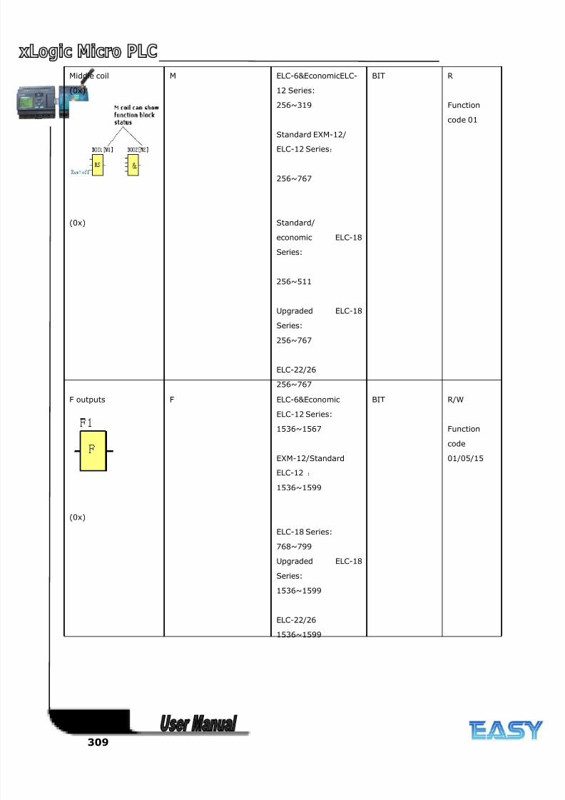
8/20/2019 XLogic User's Manual2
http://slidepdf.com/reader/full/xlogic-users-manual2 309/338
309
Middle coil
(0x)
(0x)
M ELC-6&EconomicELC-
12 Series:
256~319
Standard EXM-12/
ELC-12 Series:
256~767
Standard/
economic ELC-18
Series:
256~511
Upgraded ELC-18
Series:
256~767
ELC-22/26
256~767
BIT R
Function
code 01
F outputs
(0x)
F ELC-6&Economic
ELC-12 Series:
1536~1567
EXM-12/Standard
ELC-12 :
1536~1599
ELC-18 Series:
768~799
Upgraded ELC-18
Series:
1536~1599
ELC-22/26
1536~1599
BIT R/W
Function
code
01/05/15
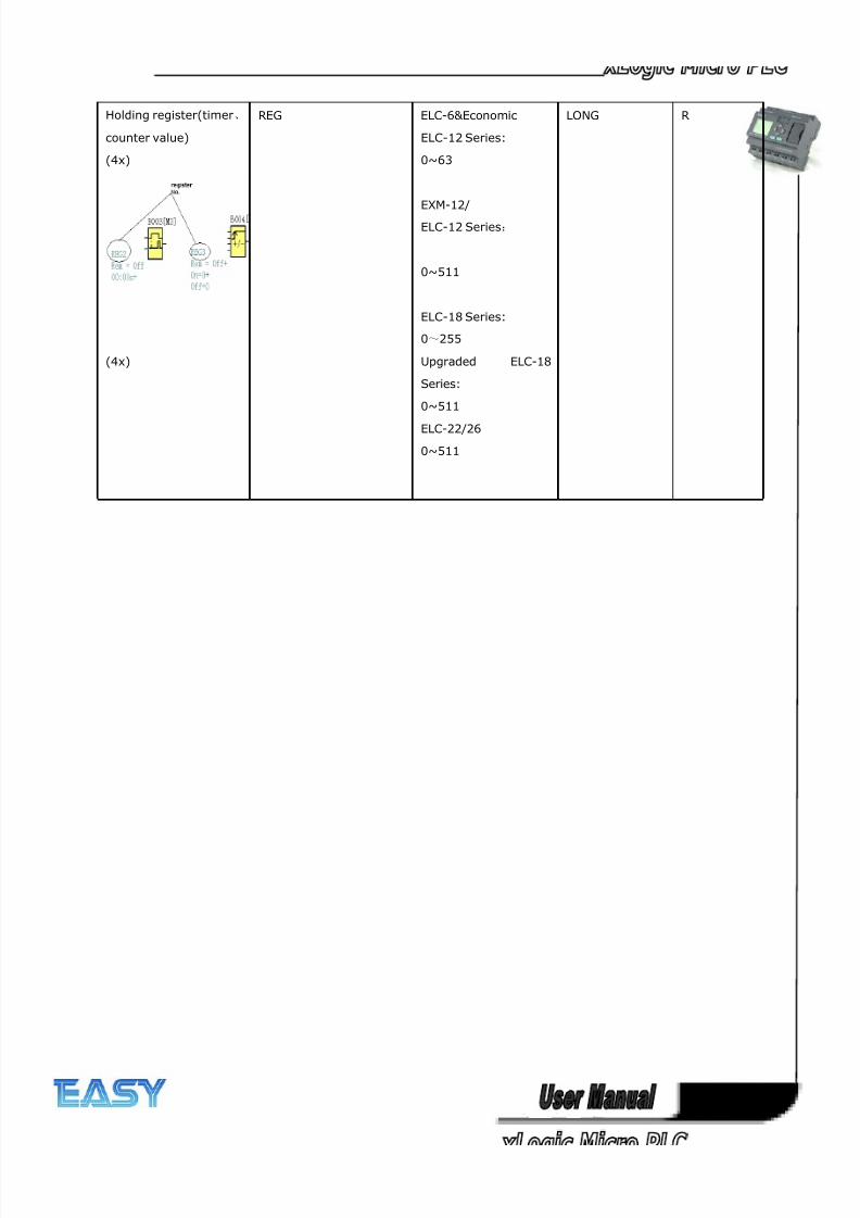
8/20/2019 XLogic User's Manual2
http://slidepdf.com/reader/full/xlogic-users-manual2 310/338
310
Holding register(timer、
counter value)
(4x)
(4x)
REG ELC-6&Economic
ELC-12 Series:
0~63
EXM-12/
ELC-12 Series:
0~511
ELC-18 Series:
0~255
Upgraded ELC-18
Series:
0~511
ELC-22/26
0~511
LONG R
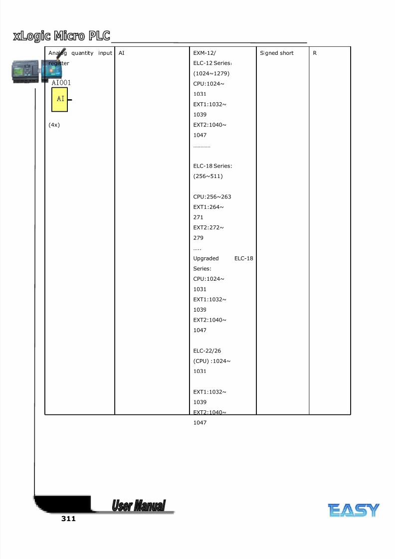
8/20/2019 XLogic User's Manual2
http://slidepdf.com/reader/full/xlogic-users-manual2 311/338
311
Analog quantity input
register
(4x)
AI EXM-12/
ELC-12 Series:
(1024~1279)
CPU:1024~
1031
EXT1:1032~
1039
EXT2:1040~
1047
…………
ELC-18 Series:
(256~511)
CPU:256~263
EXT1:264~
271
EXT2:272~
279
…..
Upgraded ELC-18
Series:
CPU:1024~
1031
EXT1:1032~
1039
EXT2:1040~
1047
ELC-22/26
(CPU) :1024~
1031
EXT1:1032~
1039
EXT2:1040~
1047
Signed short R
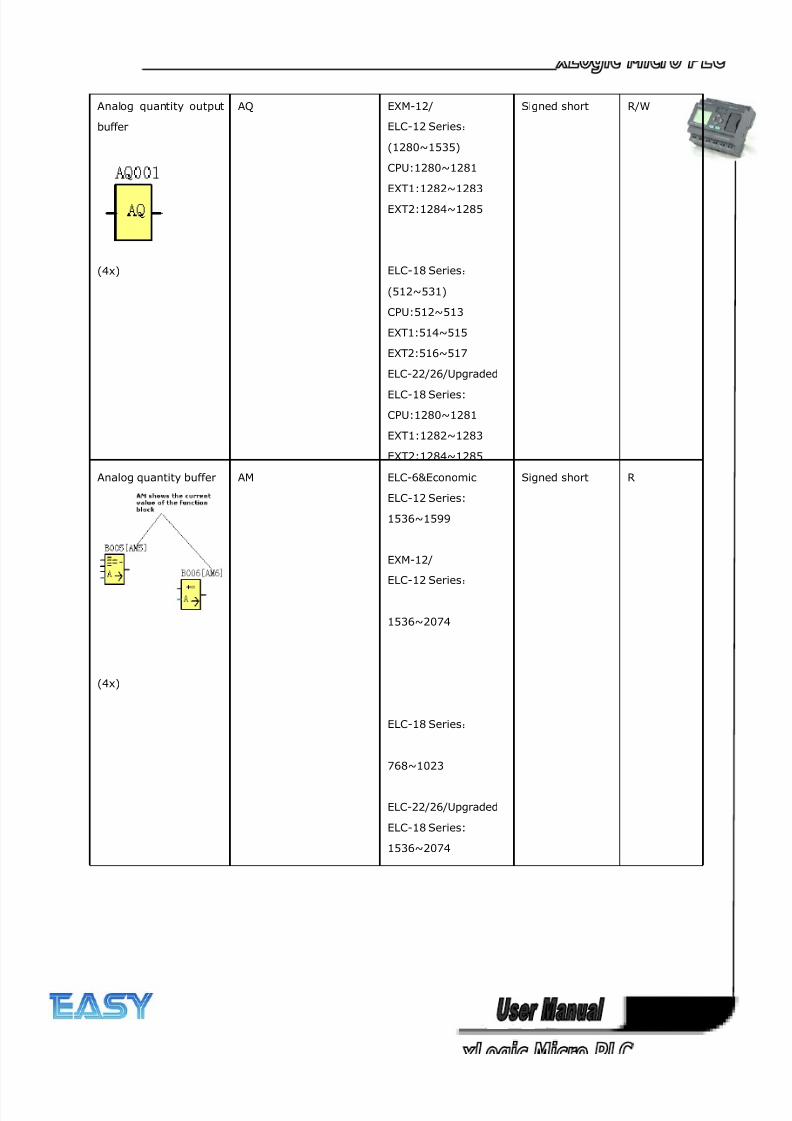
8/20/2019 XLogic User's Manual2
http://slidepdf.com/reader/full/xlogic-users-manual2 312/338
312
Analog quantity output
buffer
(4x)
AQ EXM-12/
ELC-12 Series:
(1280~1535)
CPU:1280~1281
EXT1:1282~1283
EXT2:1284~1285
ELC-18 Series:
(512~531)
CPU:512~513
EXT1:514~515
EXT2:516~517
ELC-22/26/Upgraded
ELC-18 Series:
CPU:1280~1281
EXT1:1282~1283
EXT2:1284~1285
Signed short R/W
Analog quantity buffer
(4x)
AM ELC-6&Economic
ELC-12 Series:
1536~1599
EXM-12/
ELC-12 Series:
1536~2074
ELC-18 Series:
768~1023
ELC-22/26/Upgraded
ELC-18 Series:
1536~2074
Signed short R
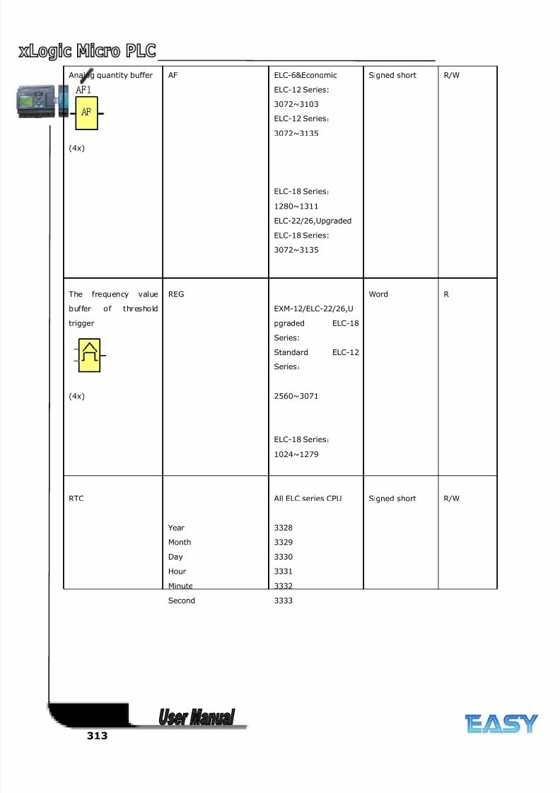
8/20/2019 XLogic User's Manual2
http://slidepdf.com/reader/full/xlogic-users-manual2 313/338
313
Analog quantity buffer
(4x)
AF ELC-6&Economic
ELC-12 Series:
3072~3103
ELC-12 Series:
3072~3135
ELC-18 Series:
1280~1311
ELC-22/26,Upgraded
ELC-18 Series:
3072~3135
Signed short R/W
The frequency value
buffer of threshold
trigger
(4x)
REG
EXM-12/ELC-22/26,U
pgraded ELC-18
Series:
Standard ELC-12
Series:
2560~3071
ELC-18 Series:
1024~1279
Word R
RTC
Year
Month
Day
Hour
Minute
Second
All ELC series CPU
3328
3329
3330
3331
3332
3333
Signed short R/W
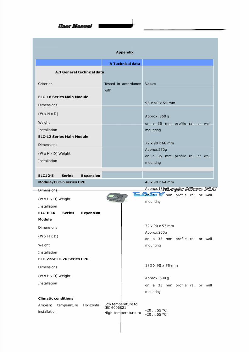
8/20/2019 XLogic User's Manual2
http://slidepdf.com/reader/full/xlogic-users-manual2 314/338
314
Appendix
A Technical data
A.1 General technical data
Criterion Tested in accordance
with
Values
ELC-18 Series Main Module
Dimensions
(W x H x D)
Weight
Installation
95 x 90 x 55 mm
Approx. 350 g
on a 35 mm pr ofil e rail or wall
mounting
ELC-12 Series Main Module
Dimensions
(W x H x D) Weight
Installation
72 x 90 x 68 mm
Approx.250g
on a 35 mm pr ofil e rail or wall
mounting
ELC1 2-E Series Expansion
Module/ELC-6 series CPU
Dimensions
(W x H x D) Weight
Installation
48 x 90 x 64 mm
Approx.180g
on a 35 mm profile rail or wall
mounting
ELC-E-16 Series Expansion
Module
Dimensions
(W x H x D)
Weight
Installation
72 x 90 x 53 mm
Approx.250g
on a 35 mm profile rail or wall
mounting
ELC-22&ELC-26 Series CPU
Dimensions
(W x H x D) Weight
Installation
133 X 90 x 55 mm
Approx. 500 g
on a 35 mm profile rail or wall
mounting
Climatic conditions
Ambient temperature Horizontal
installation
Low temperature to
IEC 6006821High temperature to
-20 ... 55 °C-20 ... 55 °C
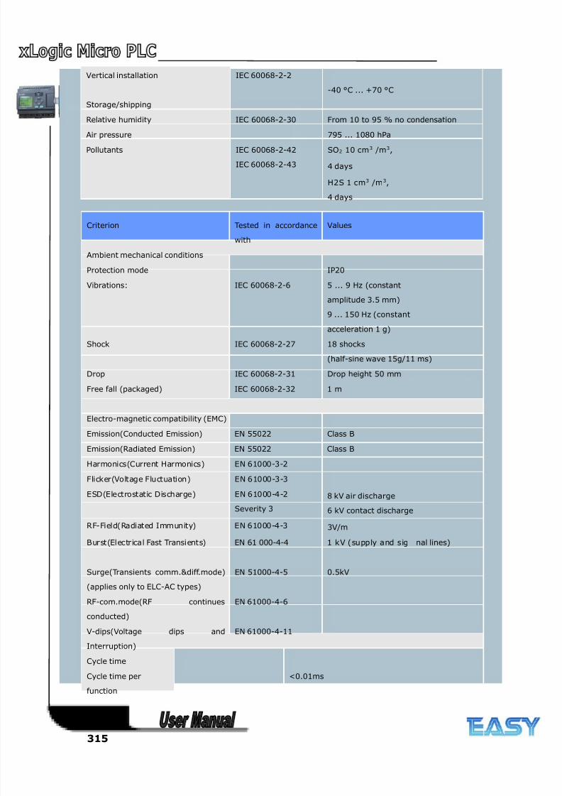
8/20/2019 XLogic User's Manual2
http://slidepdf.com/reader/full/xlogic-users-manual2 315/338
315
Vertical installation
Storage/shipping
IEC 60068-2-2
-40 °C ... +70 °C
Relative humidity IEC 60068-2-30 From 10 to 95 % no condensation
Air pressure 795 ... 1080 hPa
Pollutants IEC 60068-2-42
IEC 60068-2-43
SO2 10 cm3 /m3,
4 days
H2S 1 cm3 /m3,
4 days
Criterion Tested in accordance
with
Values
Ambient mechanical conditions
Protection mode IP20
Vibrations: IEC 60068-2-6 5 ... 9 Hz (constant
amplitude 3.5 mm)
9 ... 150 Hz (constant
acceleration 1 g)
Shock IEC 60068-2-27 18 shocks
(half-sine wave 15g/11 ms)
Drop IEC 60068-2-31 Drop height 50 mm
Free fall (packaged) IEC 60068-2-32 1 m
Electro-magnetic compatibility (EMC)
Emission(Conducted Emission) EN 55022 Class B
Emission(Radiated Emission) EN 55022 Class B
Harmonics(Current Harmonics) EN 61000-3-2
Flicker(Voltage Fluctuation) EN 61000-3-3
ESD(Electrostatic Discharge) EN 61000-4-2
Severity 3
8 kV air discharge
6 kV contact discharge
RF-Field(Radiated Immunity) EN 61000-4-3 3V/m
Burst(Electrical Fast Transients) EN 61 000-4-4 1 kV (supply and sig nal lines)
Surge(Transients comm.&diff.mode)
(applies only to ELC-AC types)
EN 51000-4-5 0.5kV
RF-com.mode(RF continues
conducted)
EN 61000-4-6
V-dips(Voltage dips and
Interruption)
EN 61000-4-11
Cycle time
Cycle time per
function
<0.01ms
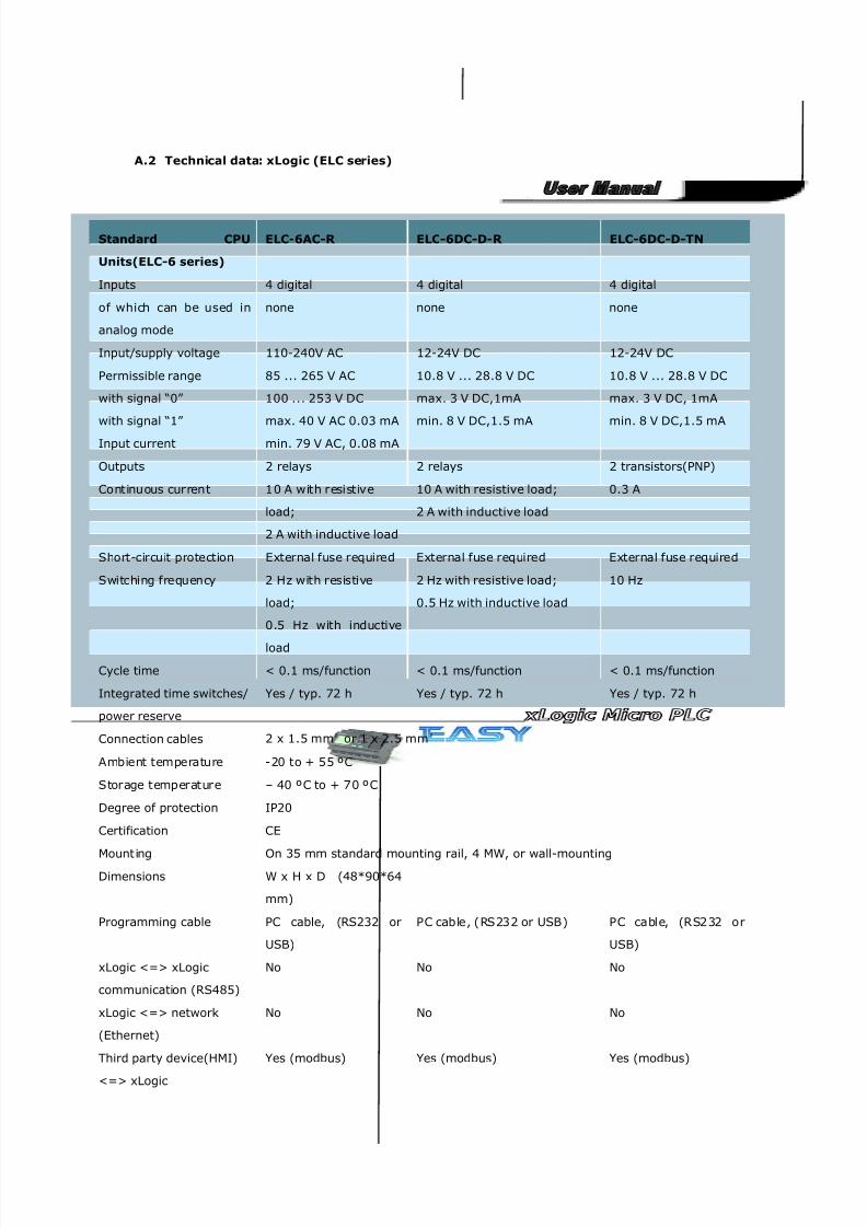
8/20/2019 XLogic User's Manual2
http://slidepdf.com/reader/full/xlogic-users-manual2 316/338
316
A.2 Technical data: xLogic (ELC series)
Standard CPU
Units(ELC-6 series)
ELC-6AC-R ELC-6DC-D-R ELC-6DC-D-TN
Inputs 4 digital 4 digital 4 digital
of which can be used in
analog mode
none none none
Input/supply voltage 110-240V AC 12-24V DC 12-24V DC
Permissible range
with signal “0”
with signal “1”
Input current
85 ... 265 V AC
100 ... 253 V DC
max. 40 V AC 0.03 mA
min. 79 V AC, 0.08 mA
10.8 V ... 28.8 V DC
max. 3 V DC,1mA
min. 8 V DC,1.5 mA
10.8 V ... 28.8 V DC
max. 3 V DC, 1mA
min. 8 V DC,1.5 mA
Outputs 2 relays 2 relays 2 transistors(PNP)
Continuous current 10 A with resistive
load;
2 A with inductive load
10 A with resistive load;
2 A with inductive load
0.3 A
Short-circuit protection External fuse required External fuse required External fuse required
Switching frequency 2 Hz with resistive
load;
0.5 Hz with inductive
load
2 Hz with resistive load;
0.5 Hz with inductive load
10 Hz
Cycle time < 0.1 ms/function < 0.1 ms/function < 0.1 ms/function
Integrated time switches/
power reserve
Yes / typ. 72 h Yes / typ. 72 h Yes / typ. 72 h
Connection cables 2 x 1.5 mm² or 1 x 2.5 mm²
Ambient temperature -20 to + 55 ºC
Storage temperature – 40 ºC to + 70 ºC
Degree of protection IP20
Certification CE
Mounting On 35 mm standard mounting rail, 4 MW, or wall-mountingDimensions W x H x D (48*90*64
mm)
Programming cable PC cable, (RS232 or
USB)
PC cable, (RS232 or USB) PC cable, (RS232 or
USB)
xLogic <=> xLogic
communication (RS485)
No No No
xLogic <=> network
(Ethernet)
No No No
Third party device(HMI)
<=> xLogic
Yes (modbus) Yes (modbus) Yes (modbus)
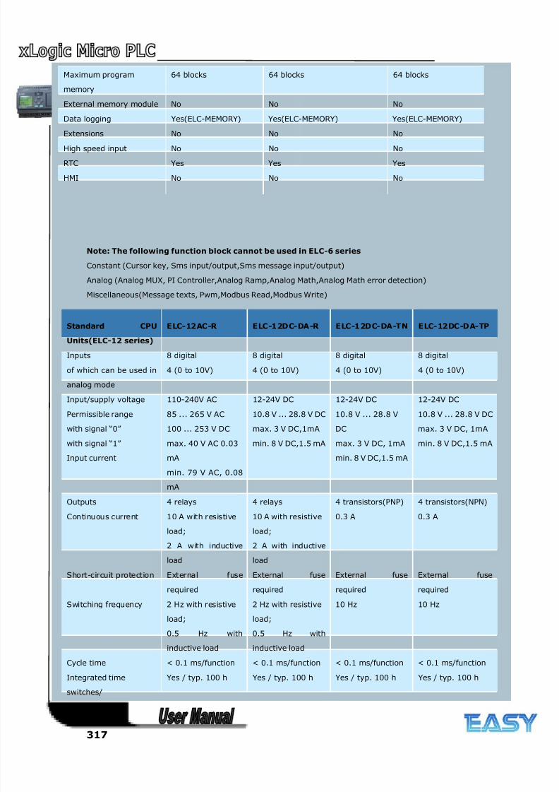
8/20/2019 XLogic User's Manual2
http://slidepdf.com/reader/full/xlogic-users-manual2 317/338
317
Note: The following function block cannot be used in ELC-6 series
Constant (Cursor key, Sms input/output,Sms message input/output)
Analog (Analog MUX, PI Controller,Analog Ramp,Analog Math,Analog Math error detection)
Miscellaneous(Message texts, Pwm,Modbus Read,Modbus Write)
Maximum program
memory
64 blocks 64 blocks 64 blocks
External memory module No No No
Data logging Yes(ELC-MEMORY) Yes(ELC-MEMORY) Yes(ELC-MEMORY)
Extensions No No No
High speed input No No No
RTC Yes Yes Yes
HMI No No No
Standard CPU
Units(ELC-12 series)
ELC-12AC-R ELC-12DC-DA-R ELC-12DC-DA-TN ELC-12DC-DA-TP
Inputs 8 digital 8 digital 8 digital 8 digital
of which can be used in
analog mode
4 (0 to 10V) 4 (0 to 10V) 4 (0 to 10V) 4 (0 to 10V)
Input/supply voltage 110-240V AC 12-24V DC 12-24V DC 12-24V DC
Permissible range
with signal “0”
with signal “1”
Input current
85 ... 265 V AC
100 ... 253 V DC
max. 40 V AC 0.03
mA
min. 79 V AC, 0.08
mA
10.8 V ... 28.8 V DC
max. 3 V DC,1mA
min. 8 V DC,1.5 mA
10.8 V ... 28.8 V
DC
max. 3 V DC, 1mA
min. 8 V DC,1.5 mA
10.8 V ... 28.8 V DC
max. 3 V DC, 1mA
min. 8 V DC,1.5 mA
Outputs 4 relays 4 relays 4 transistors(PNP) 4 transistors(NPN)
Continuous current 10 A with resistive
load;
2 A with inductive
load
10 A with resistive
load;
2 A with inductive
load
0.3 A 0.3 A
Short-circuit protection External fuse
required
External fuse
required
External fuse
required
External fuse
required
Switching frequency 2 Hz with resistive
load;
0.5 Hz with
inductive load
2 Hz with resistive
load;
0.5 Hz with
inductive load
10 Hz 10 Hz
Cycle time < 0.1 ms/function < 0.1 ms/function < 0.1 ms/function < 0.1 ms/function
Integrated time
switches/
power reserve
Yes / typ. 100 h Yes / typ. 100 h Yes / typ. 100 h Yes / typ. 100 h
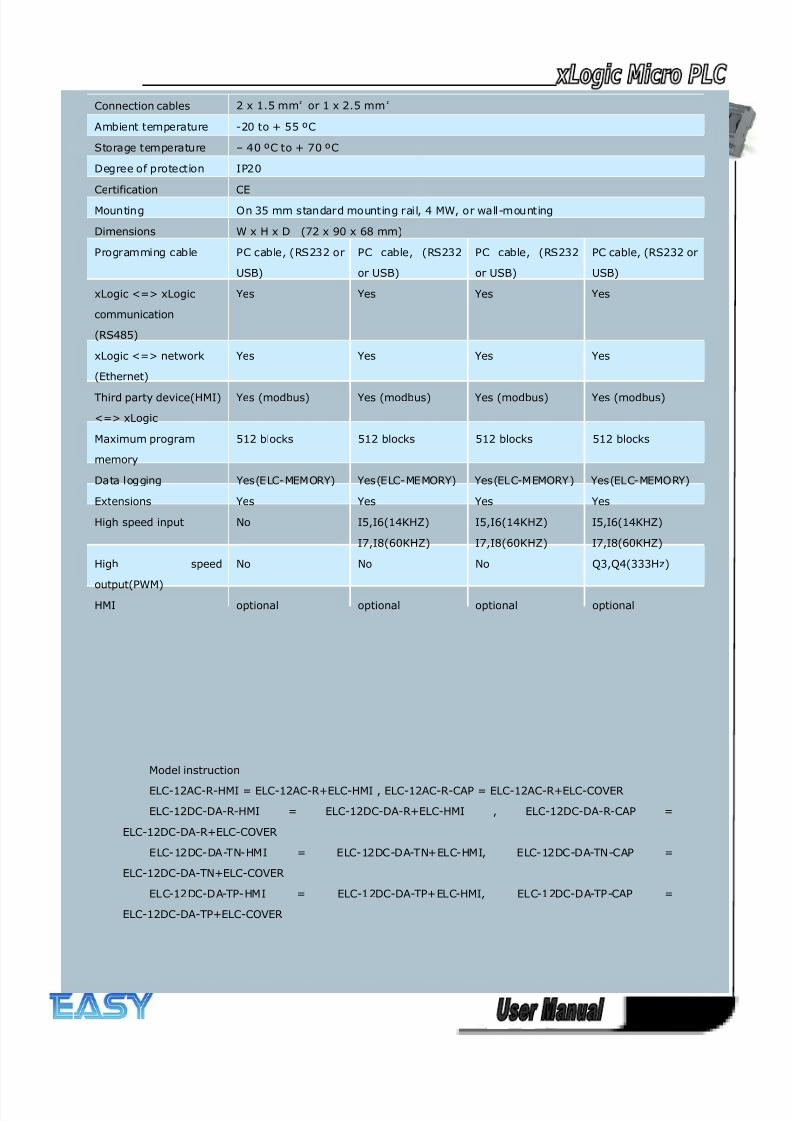
8/20/2019 XLogic User's Manual2
http://slidepdf.com/reader/full/xlogic-users-manual2 318/338
318
Model instruction
ELC-12AC-R-HMI = ELC-12AC-R+ELC-HMI , ELC-12AC-R-CAP = ELC-12AC-R+ELC-COVER
ELC-12DC-DA-R-HMI = ELC-12DC-DA-R+ELC-HMI , ELC-12DC-DA-R-CAP =
ELC-12DC-DA-R+ELC-COVER
ELC-12DC-DA-TN-HMI = ELC-12DC-DA-TN+ELC-HMI, ELC-12DC-DA-TN-CAP =
ELC-12DC-DA-TN+ELC-COVER
ELC-12DC-DA-TP-HMI = ELC-12DC-DA-TP+ELC-HMI, ELC-12DC-DA-TP-CAP =
ELC-12DC-DA-TP+ELC-COVER
Connection cables 2 x 1.5 mm² or 1 x 2.5 mm²
Ambient temperature -20 to + 55 ºC
Storage temperature – 40 ºC to + 70 ºC
Degree of protection IP20
Certification CE
Mounting On 35 mm standard mounting rail, 4 MW, or wall-mounting
Dimensions W x H x D (72 x 90 x 68 mm)
Programming cable PC cable, (RS232 or
USB)
PC cable, (RS232
or USB)
PC cable, (RS232
or USB)
PC cable, (RS232 or
USB)
xLogic <=> xLogic
communication
(RS485)
Yes Yes Yes Yes
xLogic <=> network
(Ethernet)
Yes Yes Yes Yes
Third party device(HMI)
<=> xLogic
Yes (modbus) Yes (modbus) Yes (modbus) Yes (modbus)
Maximum program
memory
512 blocks 512 blocks 512 blocks 512 blocks
Data logging Yes(ELC-MEMORY) Yes(ELC-MEMORY) Yes(ELC-MEMORY) Yes(ELC-MEMORY)
Extensions Yes Yes Yes Yes
High speed input No I5,I6(14KHZ)
I7,I8(60KHZ)
I5,I6(14KHZ)
I7,I8(60KHZ)
I5,I6(14KHZ)
I7,I8(60KHZ)
High speed
output(PWM)
No No No Q3,Q4(333Hz)
HMI optional optional optional optional
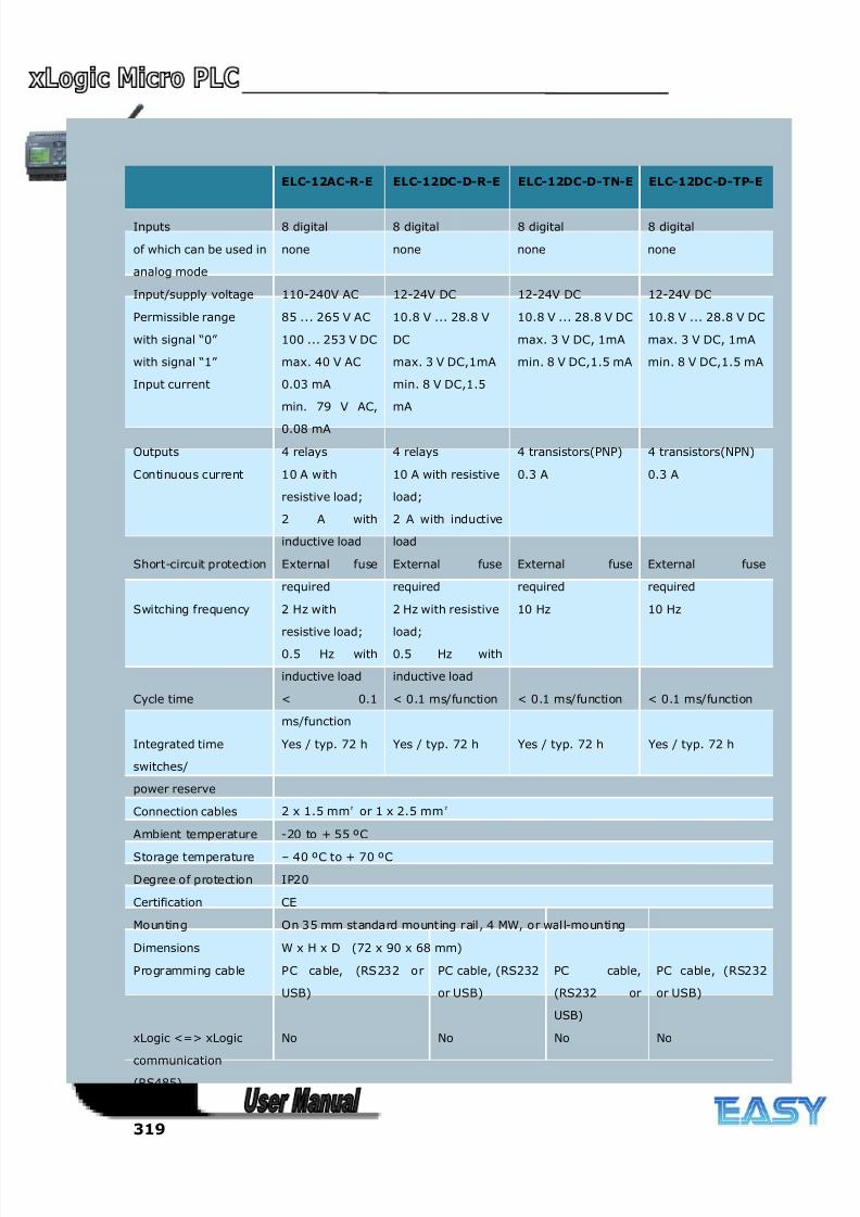
8/20/2019 XLogic User's Manual2
http://slidepdf.com/reader/full/xlogic-users-manual2 319/338
319
ELC-12AC-R-E ELC-12DC-D-R-E ELC-12DC-D-TN-E ELC-12DC-D-TP-E
Inputs 8 digital 8 digital 8 digital 8 digital
of which can be used in
analog mode
none none none none
Input/supply voltage 110-240V AC 12-24V DC 12-24V DC 12-24V DC
Permissible range
with signal “0”
with signal “1”
Input current
85 ... 265 V AC
100 ... 253 V DC
max. 40 V AC
0.03 mA
min. 79 V AC,
0.08 mA
10.8 V ... 28.8 V
DC
max. 3 V DC,1mA
min. 8 V DC,1.5
mA
10.8 V ... 28.8 V DC
max. 3 V DC, 1mA
min. 8 V DC,1.5 mA
10.8 V ... 28.8 V DC
max. 3 V DC, 1mA
min. 8 V DC,1.5 mA
Outputs 4 relays 4 relays 4 transistors(PNP) 4 transistors(NPN)
Continuous current 10 A with
resistive load;
2 A with
inductive load
10 A with resistive
load;
2 A with inductive
load
0.3 A 0.3 A
Short-circuit protection External fuse
required
External fuse
required
External fuse
required
External fuse
required
Switching frequency 2 Hz with
resistive load;
0.5 Hz with
inductive load
2 Hz with resistive
load;
0.5 Hz with
inductive load
10 Hz 10 Hz
Cycle time < 0.1
ms/function
< 0.1 ms/function < 0.1 ms/function < 0.1 ms/function
Integrated time
switches/
power reserve
Yes / typ. 72 h Yes / typ. 72 h Yes / typ. 72 h Yes / typ. 72 h
Connection cables 2 x 1.5 mm² or 1 x 2.5 mm²
Ambient temperature -20 to + 55 ºC
Storage temperature – 40 ºC to + 70 ºC
Degree of protection IP20
Certification CE
Mounting On 35 mm standard mounting rail, 4 MW, or wall-mounting
Dimensions W x H x D (72 x 90 x 68 mm)
Programming cable PC cable, (RS232 or
USB)
PC cable, (RS232
or USB)
PC cable,
(RS232 or
USB)
PC cable, (RS232
or USB)
xLogic <=> xLogic
communication(RS485)
No No No No
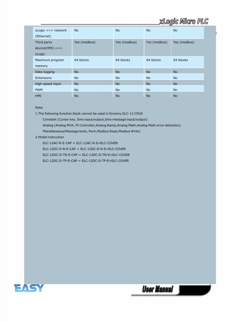
8/20/2019 XLogic User's Manual2
http://slidepdf.com/reader/full/xlogic-users-manual2 320/338
320
xLogic <=> network
(Ethernet)
No No No No
Third party
device(HMI) <=>
xLogic
Yes (modbus) Yes (modbus) Yes (modbus) Yes (modbus)
Maximum program
memory
64 blocks 64 blocks 64 blocks 64 blocks
Data logging No No No No
Extensions No No No No
High speed input No No No No
PWM No No No No
HMI No No No No
Note:
1.The following function block cannot be used in Ecnomy ELC-12 CPUS
Constant (Cursor key, Sms input/output,Sms message input/output)
Analog (Analog MUX, PI Controller,Analog Ramp,Analog Math,Analog Math error detection)
Miscellaneous(Message texts, Pwm,Modbus Read,Modbus Write)
2.Model instruction
ELC-12AC-R-E-CAP = ELC-12AC-R-E+ELC-COVER
ELC-12DC-D-R-E-CAP = ELC-12DC-D-R-E+ELC-COVER
ELC-12DC-D-TN-E-CAP = ELC-12DC-D-TN-E+ELC-COVER
ELC-12DC-D-TP-E-CAP = ELC-12DC-D-TP-E+ELC-COVER
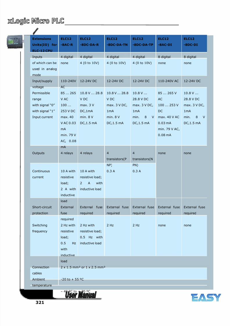
8/20/2019 XLogic User's Manual2
http://slidepdf.com/reader/full/xlogic-users-manual2 321/338
321
Extensions
Units(IO) for
ELC-12 CPU
ELC12
-8AC-R
ELC12
-8DC-DA-R
ELC12
-8DC-DA-TN
ELC12
-8DC-DA-TP
ELC12
-8AC-DI
ELC12
-8DC-DI
Inputs 4 digital 4 digital 4 digital 4 digital 8 digital 8 digital
of which can be
used in analog
mode
none 4 (0 to 10V) 4 (0 to 10V) 4 (0 to 10V) none none
Input/supply
voltage
110-240V
AC
12-24V DC 12-24V DC 12-24V DC 110-240V AC 12-24V DC
Permissible
range
with signal “0”
with signal “1”
Input current
85 ... 265
V AC
100 ...
253 V DC
max. 40
V AC 0.03
mA
min. 79 V
AC, 0.08
mA
10.8 V ... 28.8
V DC
max. 3 V
DC,1mA
min. 8 V
DC,1.5 mA
10.8 V ... 28.8
V DC
max. 3 V DC,
1mA
min. 8 V
DC,1.5 mA
10.8 V ...
28.8 V DC
max. 3 V DC,
1mA
min. 8 V
DC,1.5 mA
85 ... 265 V
AC
100 ... 253 V
DC
max. 40 V AC
0.03 mA
min. 79 V AC,
0.08 mA
10.8 V ...
28.8 V DC
max. 3 V DC,
1mA
min. 8 V
DC,1.5 mA
Outputs 4 relays 4 relays 4
transistors(P
NP)
4
transistors(N
PN)
none none
Continuous
current
10 A with
resistive
load;
2 A with
inductive
load
10 A with
resistive load;
2 A with
inductive load
0.3 A 0.3 A
Short-circuit
protection
External
fuse
required
External fuse
required
External fuse
required
External fuse
required
External fuse
required
External fuse
required
Switching
frequency
2 Hz with
resistive
load;
0.5 Hz
with
inductive
load
2 Hz with
resistive load;
0.5 Hz with
inductive load
2 Hz 2 Hz none none
Connection
cables
2 x 1.5 mm² or 1 x 2.5 mm²
Ambient
temperature
-20 to + 55 ºC
Storage – 40 ºC to + 70 ºC
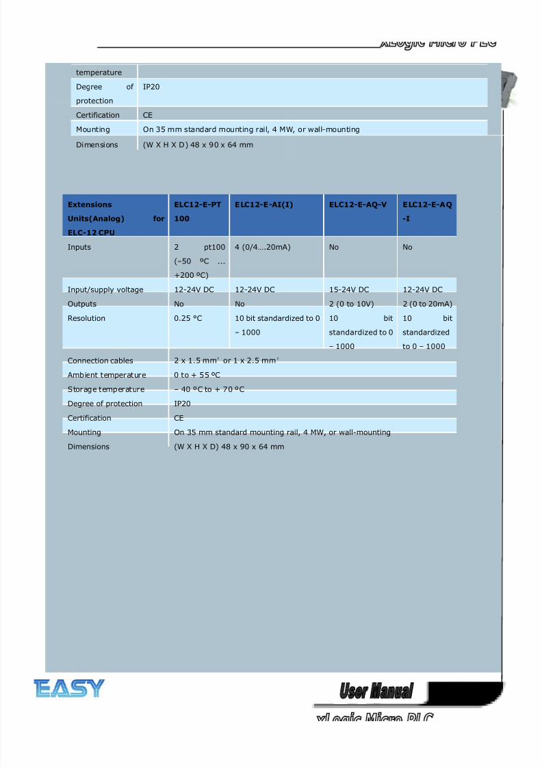
8/20/2019 XLogic User's Manual2
http://slidepdf.com/reader/full/xlogic-users-manual2 322/338
322
temperature
Degree of
protection
IP20
Certification CE
Mounting On 35 mm standard mounting rail, 4 MW, or wall-mounting
Dimensions (W X H X D) 48 x 90 x 64 mm
Extensions
Units(Analog) for
ELC-12 CPU
ELC12-E-PT
100
ELC12-E-AI(I) ELC12-E-AQ-V ELC12-E-A Q
-I
Inputs 2 pt100
(–50 ºC ...
+200 ºC)
4 (0/4….20mA) No No
Input/supply voltage 12-24V DC 12-24V DC 15-24V DC 12-24V DC
Outputs No No 2 (0 to 10V) 2 (0 to 20mA)
Resolution 0.25 °C 10 bit standardized to 0
– 1000
10 bit
standardized to 0
– 1000
10 bit
standardized
to 0 – 1000
Connection cables 2 x 1.5 mm² or 1 x 2.5 mm²
Ambient temperature 0 to + 55 ºC
Storage temperature – 40 ºC to + 70 ºC
Degree of protection IP20
Certification CE
Mounting On 35 mm standard mounting rail, 4 MW, or wall-mounting
Dimensions (W X H X D) 48 x 90 x 64 mm
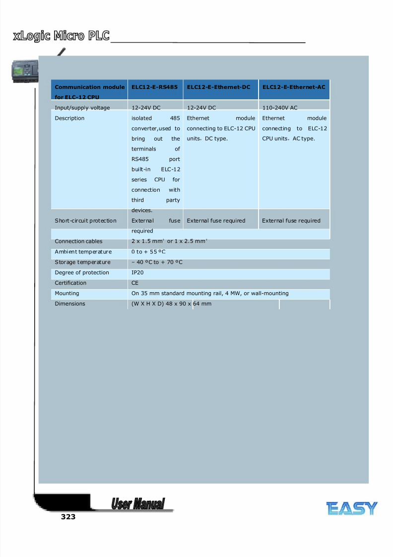
8/20/2019 XLogic User's Manual2
http://slidepdf.com/reader/full/xlogic-users-manual2 323/338
323
Communication module
for ELC-12 CPU
ELC12-E-RS485 ELC12-E-Ethernet-DC ELC12-E-Ethernet-AC
Input/supply voltage 12-24V DC 12-24V DC 110-240V AC
Description isolated 485
converter,used to
bring out the
terminals of
RS485 port
built-in ELC-12
series CPU for
connection with
third party
devices.
Ethernet module
connecting to ELC-12 CPU
units,DC type.
Ethernet module
connecting to ELC-12
CPU units,AC type.
Short-circuit protection External fuse
required
External fuse required External fuse required
Connection cables 2 x 1.5 mm² or 1 x 2.5 mm²
Ambient temperature 0 to + 55 ºC
Storage temperature – 40 ºC to + 70 ºC
Degree of protection IP20
Certification CE
Mounting On 35 mm standard mounting rail, 4 MW, or wall-mounting
Dimensions (W X H X D) 48 x 90 x 64 mm
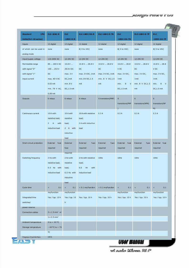
8/20/2019 XLogic User's Manual2
http://slidepdf.com/reader/full/xlogic-users-manual2 324/338
324
Standard CPU
Units(ELC-18 series)
E LC- 18 AC -R E LC
-18DC-D-R
ELC-18DC-DA-R ELC-18DC-D-TN ELC
-18DC-DA-TN
ELC-18DC-D-TP ELC
-18DC-DA-TP
Inputs 12 digital 12 digital 12 digital 12 digital 12 digital 12 digital 12 digital
of which can be used in
analog mode
none none 8( 0 to 10V) none 8( 0 to 10V) none 8( 0 to 10V)
Input/supply voltage 110-240V AC 12-24V DC 12-24V DC 12-24V DC 12-24V DC 12-24V DC 12-24V DC
Permissible range
with signal “0”
with signal “1”
Input current
85 ... 265 V AC
100 ... 253 V
DC
max. 40 V AC
0.03 mA
min. 79 V AC,
0.08 mA
10.8 V ...
28.8 V DC
max. 3 V
DC,1mA
min. 8 V
DC,1.5 mA
10.8 V ... 28.8 V
DC
max. 3 V DC, 1mA
min. 8 V DC,1.5
mA
10.8 V ... 28.8 V
DC
max. 3 V DC, 1mA
min. 8 V DC,1.5
mA
10.8 V ... 28.8
V DC
max. 3 V DC,
1mA
min. 8 V
DC,1.5 mA
10.8 V ... 28.8 V
DC
max. 3 V DC,
1mA
min. 8 V DC,1.5
mA
10.8 V ... 28.8
V DC
max. 3 V DC,
1mA
min. 8 V
DC,1.5 mA
Outputs 6 relays 6 relays 6 relays 6 transistors(PNP) 6
transistors(PNP
)
6
transistors(NPN)
6
transistors(NP
N)
Con ti nu ou s current 10 A w it h
resistive load;
2 A with
inductive load
10 A with
resistive
load;
2 A with
inductive
load
10 A with resistive
load;
2 A with inductive
load
0.3 A 0.3 A 0.3 A 0.3 A
Short-circuit protection External fuse
required
External
fuse
required
E xt er na l f us e
required
E xt er na l f us e
required
External fuse
required
E xt ernal fuse
required
External fuse
required
Swi tchi ng frequ en cy 2 H z w it h
resistive load;
0. 5 Hz with
inductive load
2 Hz with
resistive
load;
0.5 Hz with
inductive
load
2 Hz with resistive
load;
0.5 Hz with
inductive load
10Hz 10Hz 10Hz 10Hz
Cycle time < 0.1
ms/function
< 0.1
ms/function
< 0 .1 ms /f unc tio n < 0. 1 m s/f unc tion < 0. 1
ms/function
< 0.1
ms/function
< 0.1
ms/function
Integrated time
switches/
power reserve
Yes / typ. 10 h Yes / typ. 10
h
Yes / typ. 10 h Yes / typ. 10 h Yes / typ. 10 h Yes / typ. 10 h Yes / typ. 10 h
Connection cables 2 x 1.5 mm² or
1 x 2.5 mm²
Ambient temperature 0 to + 55 ºC
Storage temperature – 40 ºC to + 70
ºC
D egree o f pro tect io n I P20
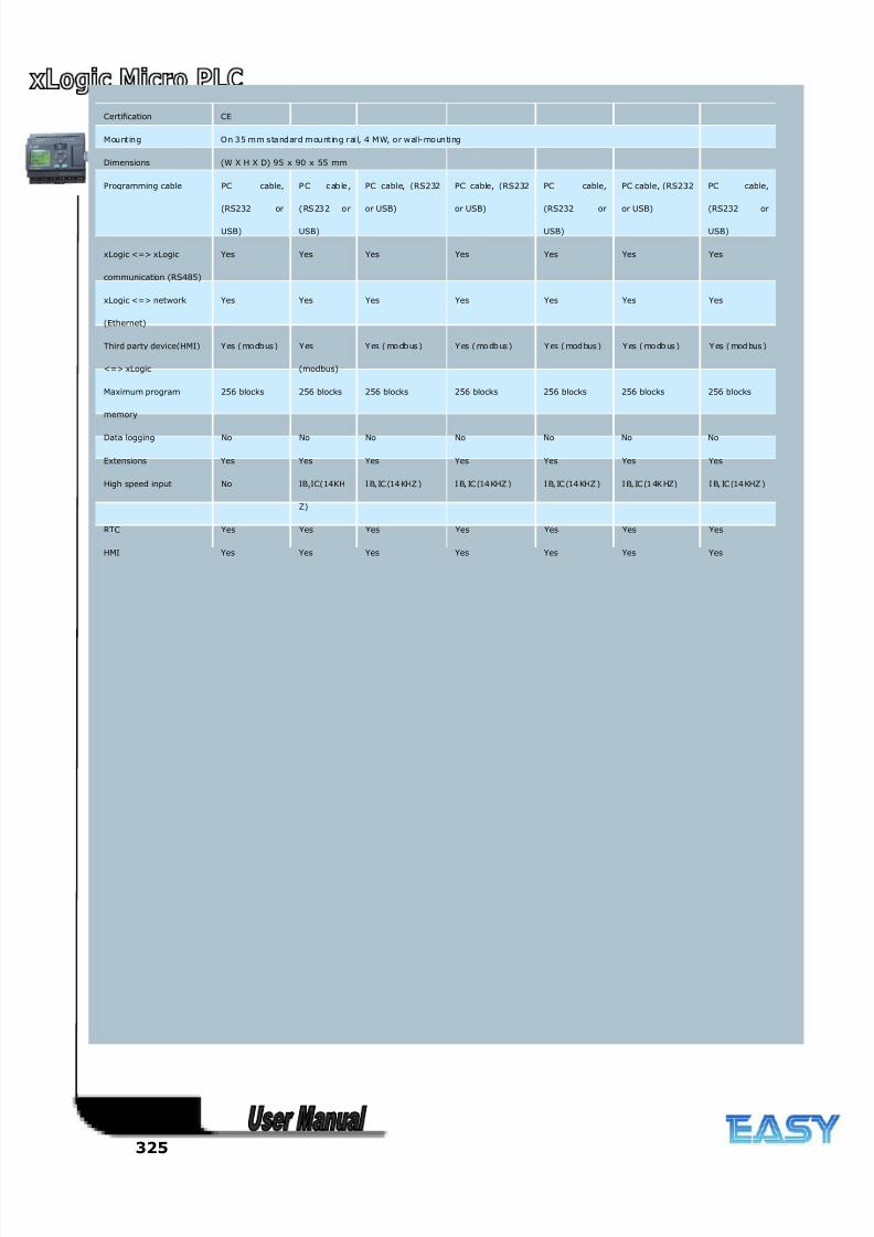
8/20/2019 XLogic User's Manual2
http://slidepdf.com/reader/full/xlogic-users-manual2 325/338
325
Certification CE
M ou nt in g On 35 mm standard mou nt in g rai l, 4 M W, o r w al l-mo un ti ng
Dimensions (W X H X D) 95 x 90 x 55 mm
Programming cable PC cable,
(RS232 or
USB)
P C c ab le ,
(RS232 o r
USB)
PC cable, (RS232
or USB)
PC cable, (RS232
or USB)
PC cable,
(RS232 or
USB)
PC cable, (RS232
or USB)
PC cable,
(RS232 or
USB)
xLogic <=> xLogic
communication (RS485)
Yes Yes Yes Yes Yes Yes Yes
xLogic <=> network
(Ethernet)
Yes Yes Yes Yes Yes Yes Yes
Third party device(HMI)
<=> xLogic
Yes (mo dbus) Yes
(modbus)
Y es ( mo db us ) Y es ( mo db us ) Y es ( mod bus ) Y es ( mo db us ) Y es ( mod bus )
Maximum program
memory
256 blocks 256 blocks 256 blocks 256 blocks 256 blocks 256 blocks 256 blocks
Data logging No No No No No No No
Extensions Yes Yes Yes Yes Yes Yes Yes
High speed input No IB,IC(14KH
Z)
I B, IC (14 KHZ ) I B, IC (14 KHZ ) I B, IC (14 KHZ ) I B, IC (1 4K HZ) I B, IC (14 KHZ )
RTC Yes Yes Yes Yes Yes Yes Yes
HMI Yes Yes Yes Yes Yes Yes Yes
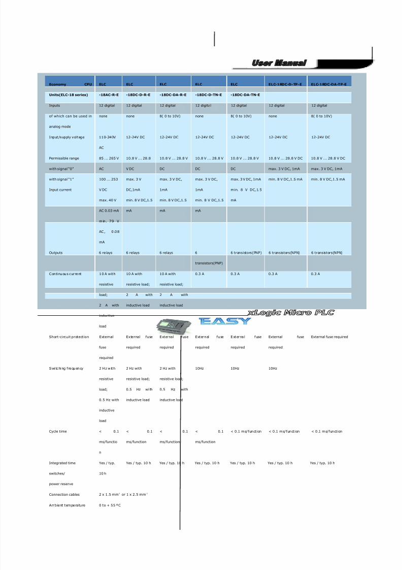
8/20/2019 XLogic User's Manual2
http://slidepdf.com/reader/full/xlogic-users-manual2 326/338
326
Economy CPU
Units(ELC-18 series)
ELC
-18AC-R-E
ELC
-18DC-D-R-E
ELC
-18DC-DA-R-E
ELC
-18DC-D-TN-E
ELC
-18DC-DA-TN-E
ELC-18DC-D-TP-E ELC-18DC-DA-TP-E
Inputs 12 digital 12 digital 12 digital 12 digital 12 digital 12 digital 12 digital
of which can be used in
analog mode
none none 8( 0 to 10V) none 8( 0 to 10V) none 8( 0 to 10V)
Input/supply voltage 110-240V
AC
12-24V DC 12-24V DC 12-24V DC 12-24V DC 12-24V DC 12-24V DC
Permissible range
with signal “0”
with signal “1”
Input current
85 ... 265 V
AC
100 ... 253
V DC
max. 40 V
AC 0.03 mA
m in . 79 V
AC , 0 .0 8
mA
10.8 V ... 28.8
V DC
max. 3 V
DC,1mA
min. 8 V DC,1.5
mA
10.8 V ... 28.8 V
DC
max. 3 V DC,
1mA
min. 8 V DC,1.5
mA
10.8 V ... 28.8 V
DC
max. 3 V DC,
1mA
min. 8 V DC,1.5
mA
10.8 V ... 28.8 V
DC
max. 3 V DC, 1mA
min. 8 V DC,1.5
mA
10.8 V ... 28.8 V DC
max. 3 V DC, 1mA
min. 8 V DC,1.5 mA
10.8 V ... 28.8 V DC
max. 3 V DC, 1mA
min. 8 V DC,1.5 mA
Outputs 6 relays 6 relays 6 relays 6
transistors(PNP)
6 transistors(PNP) 6 transistors(NPN) 6 transistors(NPN)
C on tinu ou s c urre nt 10 A wit h
resistive
load;
2 A with
inductive
load
10 A with
resistive load;
2 A with
inductive load
10 A with
resistive load;
2 A with
inductive load
0.3 A 0.3 A 0.3 A 0.3 A
Short-circuit protection External
fuse
required
External fuse
required
External fuse
required
External fuse
required
E xt er na l f use
required
External fuse
required
External fuse required
S witc hing fre qu en cy 2 H z wit h
resistive
load;
0.5 Hz with
inductive
load
2 Hz with
resistive load;
0.5 Hz wi th
inductive load
2 Hz with
resistive load;
0.5 Hz with
inductive load
10Hz 10Hz 10Hz
Cycle time < 0.1
ms/functio
n
< 0.1
ms/function
< 0.1
ms/function
< 0.1
ms/function
< 0.1 ms/function < 0.1 ms/function < 0.1 ms/function
Integrated time
switches/
power reserve
Yes / typ.
10 h
Yes / typ. 10 h Yes / typ. 10 h Yes / typ. 10 h Yes / typ. 10 h Yes / typ. 10 h Yes / typ. 10 h
Connection cables 2 x 1.5 mm² or 1 x 2.5 mm²
Ambient temperature 0 to + 55 ºC
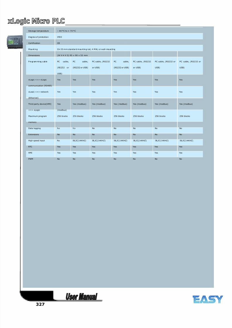
8/20/2019 XLogic User's Manual2
http://slidepdf.com/reader/full/xlogic-users-manual2 327/338
327
Storage temperature – 40 ºC to + 70 ºC
Deg re e o f p ro te ct io n I P20
Certification CE
M ou nt in g O n 35 m m s ta nd ard m ou nt in g rail, 4 M W, o r wall-mo un ting
Dimensions (W X H X D) 95 x 90 x 55 mm
P ro gr am mi ng c ab le PC ca bl e,
(RS232 or
USB)
PC cable,
(RS232 or USB)
PC cable, (RS232
or USB)
PC cable,
(RS232 or USB)
PC cable, (RS232
or USB)
PC cable, (RS232 or
USB)
PC cable, (RS232 or
USB)
xLogic <=> xLogic
communication (RS485)
Yes Yes Yes Yes Yes Yes Yes
xLogic <=> network
(Ethernet)
Yes Yes Yes Yes Yes Yes Yes
Third party device(HMI)
<=> xLogic
Yes
(modbus)
Yes (modbus) Yes (modbus) Yes ( modbus) Yes (modbus) Yes (modbus) Yes (modbus)
Maximum program
memory
256 blocks 256 blocks 256 blocks 256 blocks 256 blocks 256 blocks 256 blocks
Data logging No No No No No No No
Extensions No No No No No No No
High speed input No IB,IC(14KHZ) IB,IC(14KHZ) IB,IC(14KHZ) IB,IC(14KHZ) IB,IC(14KHZ) IB,IC(14KHZ)
RTC Yes Yes Yes Yes Yes Yes Yes
HMI Yes Yes Yes Yes Yes Yes Yes
PWM No No No No No No No
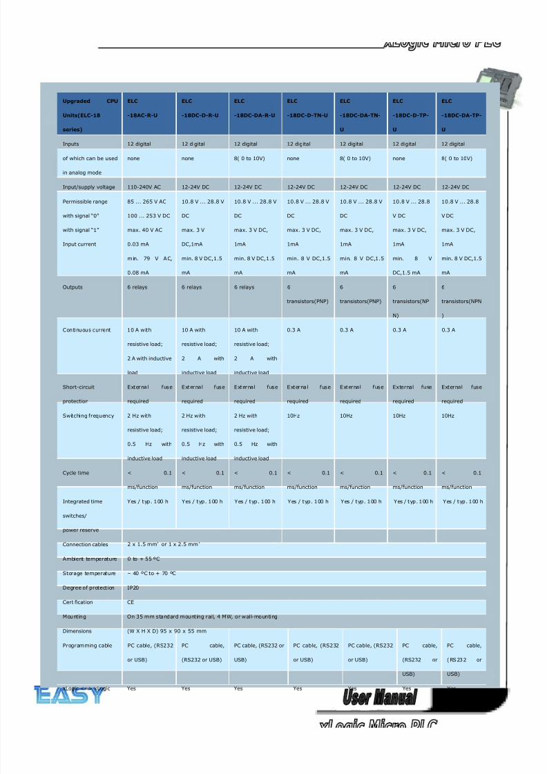
8/20/2019 XLogic User's Manual2
http://slidepdf.com/reader/full/xlogic-users-manual2 328/338
328
Upgraded CPU
Units(ELC-18
series)
ELC
-18AC-R-U
ELC
-18DC-D-R-U
ELC
-18DC-DA-R-U
ELC
-18DC-D-TN-U
ELC
-18DC-DA-TN-
U
ELC
-18DC-D-TP-
U
ELC
-18DC-DA-TP-
U
Inputs 12 digital 12 digital 12 digital 12 digital 12 digital 12 digital 12 digital
of which can be used
in analog mode
none none 8( 0 to 10V) none 8( 0 to 10V) none 8( 0 to 10V)
Input/supply voltage 110-240V AC 12-24V DC 12-24V DC 12-24V DC 12-24V DC 12-24V DC 12-24V DC
Permissible range
with signal “0”
with signal “1”
Input current
85 ... 265 V AC
100 ... 253 V DC
max. 40 V AC
0.03 mA
m in. 79 V A C,
0.08 mA
10.8 V ... 28.8 V
DC
max. 3 V
DC,1mA
min. 8 V DC,1.5
mA
10.8 V ... 28.8 V
DC
max. 3 V DC,
1mA
min. 8 V DC,1.5
mA
10.8 V ... 28.8 V
DC
max. 3 V DC,
1mA
min. 8 V DC,1.5
mA
10.8 V ... 28.8 V
DC
max. 3 V DC,
1mA
min. 8 V DC,1.5
mA
10.8 V ... 28.8
V DC
max. 3 V DC,
1mA
min. 8 V
DC,1.5 mA
10.8 V ... 28.8
V DC
max. 3 V DC,
1mA
min. 8 V DC,1.5
mA
Outputs 6 relays 6 relays 6 relays 6
transistors(PNP)
6
transistors(PNP)
6
transistors(NP
N)
6
transistors(NPN
)
Continuous current 10 A with
resistive load;
2 A with inductive
load
10 A with
resistive load;
2 A with
inductive load
10 A with
resistive load;
2 A with
inductive load
0.3 A 0.3 A 0.3 A 0.3 A
Short-circuit
protection
E xt ernal fuse
required
E xt ernal fuse
required
E xt ernal fuse
required
E xt ernal fuse
required
E xt ernal fuse
required
External fuse
required
External fuse
required
Switching frequency 2 Hz with
resistive load;
0.5 Hz with
inductive load
2 Hz with
resistive load;
0.5 Hz with
inductive load
2 Hz with
resistive load;
0.5 Hz with
inductive load
10Hz 10Hz 10Hz 10Hz
Cycle time < 0.1
ms/function
< 0.1
ms/function
< 0.1
ms/function
< 0.1
ms/function
< 0.1
ms/function
< 0.1
ms/function
< 0.1
ms/function
Integrated time
switches/
power reserve
Yes / t yp. 100 h Yes / t yp. 100 h Yes / t yp. 100 h Yes / t yp. 100 h Yes / t yp. 100 h Yes / t yp. 100 h Yes / t yp. 100 h
Connection cables 2 x 1.5 mm² or 1 x 2.5 mm²
Ambient temperature 0 to + 55 ºC
Storage temperature – 40 ºC to + 70 ºC
Degree of protection IP20
Certification CE
Mounting On 35 mm standard mounting rail, 4 MW, or wall-mounting
Dimensions (W X H X D) 95 x 90 x 55 mm
Programming cable PC cable, (RS232
or USB)
PC cable,
(RS232 or USB)
PC cable, (RS232 or
USB)
PC cable, (RS232
or USB)
PC cable, (RS232
or USB)
PC cable,
(RS232 or
USB)
PC cable,
( RS 23 2 or
USB)
xLogic <=> xLogic Yes Yes Yes Yes Yes Yes Yes
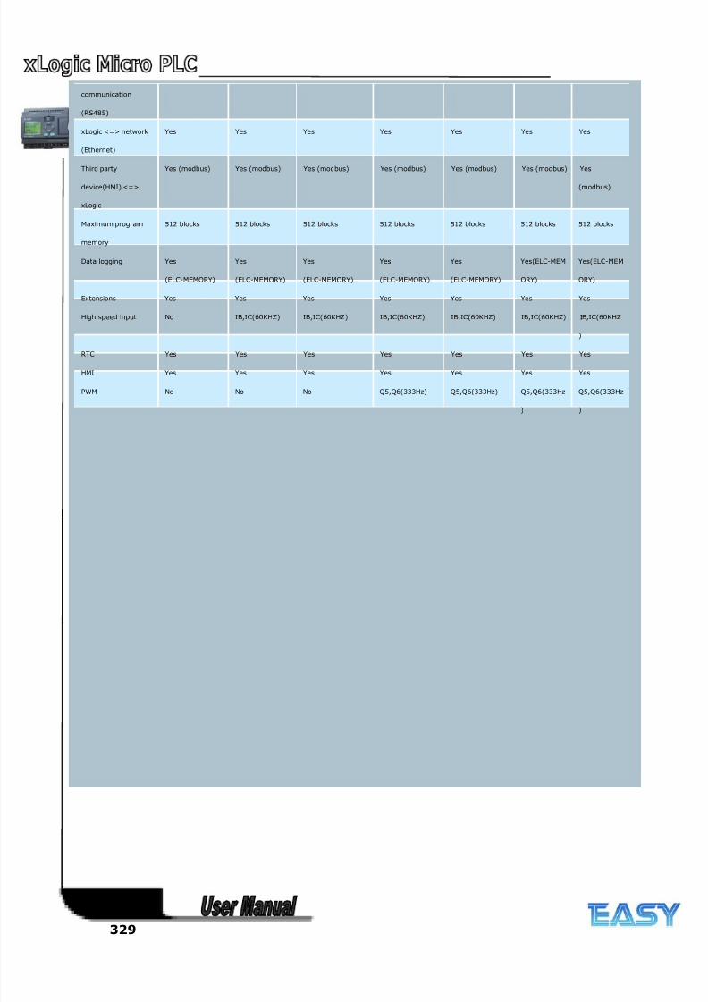
8/20/2019 XLogic User's Manual2
http://slidepdf.com/reader/full/xlogic-users-manual2 329/338
329
communication
(RS485)
xLogic <=> network
(Ethernet)
Yes Yes Yes Yes Yes Yes Yes
Third party
device(HMI) <=>
xLogic
Yes (modbus) Yes (modbus) Yes (modbus) Yes (modbus) Yes (modbus) Yes (modbus) Yes
(modbus)
Maximum program
memory
512 blocks 512 blocks 512 blocks 512 blocks 512 blocks 512 blocks 512 blocks
Data logging Yes
(ELC-MEMORY)
Yes
(ELC-MEMORY)
Yes
(ELC-MEMORY)
Yes
(ELC-MEMORY)
Yes
(ELC-MEMORY)
Yes(ELC-MEM
ORY)
Yes(ELC-MEM
ORY)
Extensions Yes Yes Yes Yes Yes Yes Yes
High speed input No IB,IC(60KHZ) IB,IC(60KHZ) IB,IC(60KHZ) IB,IC(60KHZ) IB,IC(60KHZ) IB,IC(60KHZ
)
RTC Yes Yes Yes Yes Yes Yes Yes
HMI Yes Yes Yes Yes Yes Yes Yes
PWM No No No Q5,Q6(333Hz) Q5,Q6(333Hz) Q5,Q6(333Hz
)
Q5,Q6(333Hz
)
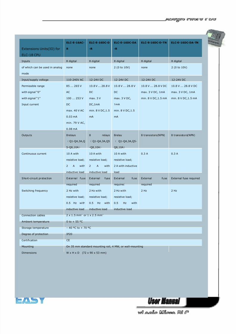
8/20/2019 XLogic User's Manual2
http://slidepdf.com/reader/full/xlogic-users-manual2 330/338
330
Extensions Units(IO) for
ELC-18 CPU
ELC-E-16AC-
R
ELC-E-16DC-D
-R
ELC-E-16DC-DA
-R
ELC-E-16DC-D-TN ELC-E-16DC-DA-TN
Inputs 8 digital 8 digital 8 digital 8 digital 8 digital
of which can be used in analog
mode
none none 2 (0 to 10V) none 2 (0 to 10V)
Input/supply voltage 110-240V AC 12-24V DC 12-24V DC 12-24V DC 12-24V DC
Permissible range
with signal “0”
with signal “1”
Input current
85 ... 265 V
AC
100 ... 253 V
DC
max. 40 V AC
0.03 mA
min. 79 V AC,
0.08 mA
10.8 V ... 28.8 V
DC
max. 3 V
DC,1mA
min. 8 V DC,1.5
mA
10.8 V ... 28.8 V
DC
max. 3 V DC,
1mA
min. 8 V DC,1.5
mA
10.8 V ... 28.8 V DC
max. 3 V DC, 1mA
min. 8 V DC,1.5 mA
10.8 V ... 28.8 V DC
max. 3 V DC, 1mA
min. 8 V DC,1.5 mA
Outputs 8relays
(Q1-Q4,3A,Q
5-Q8,10A)
8 relays
( Q1-Q4,3A,Q5
-Q8,10A)
8relay
( Q1-Q4,3A,Q5-
Q8,10A)
8 transistors(NPN) 8 transistors(NPN)
Continuous current 10 A with
resistive load;
2 A with
inductive load
10 A with
resistive load;
2 A with
inductive load
10 A with
resistive load;
2 A with inductive
load
0.3 A 0.3 A
S ho rt-c ir cuit pr otec ti on Exter na l fus e
required
External fuse
required
Ext ernal fuse
required
External fuse
required
External fuse required
Switching frequency 2 Hz with
resistive load;
0 .5 Hz wi th
inductive load
2 Hz with
resistive load;
0.5 Hz with
inductive load
2 Hz with
resistive load;
0.5 Hz with
inductive load
2 Hz 2 Hz
Connection cables 2 x 1.5 mm² or 1 x 2.5 mm²
Ambient temperature 0 to + 55 ºC
Storage temperature – 40 ºC to + 70 ºC
Degree of protection IP20
Certification CE
Mounting On 35 mm standard mounting rail, 4 MW, or wall-mounting
Dimensions W x H x D (72 x 90 x 53 mm)
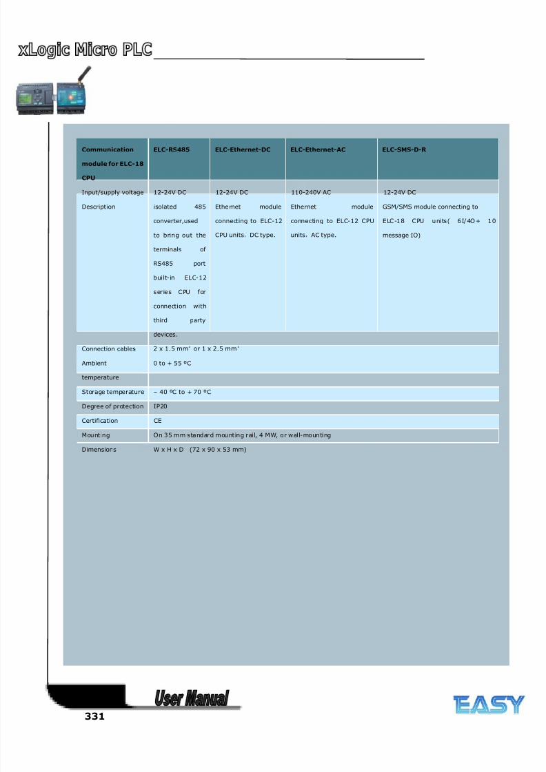
8/20/2019 XLogic User's Manual2
http://slidepdf.com/reader/full/xlogic-users-manual2 331/338
331
Communication
module for ELC-18
CPU
ELC-RS485 ELC-Ethernet-DC ELC-Ethernet-AC ELC-SMS-D-R
Input/supply voltage 12-24V DC 12-24V DC 110-240V AC 12-24V DC
Description isolated 485
converter,used
to bring out the
terminals of
RS485 port
built-in ELC-12
s er ies CPU for
connection with
third party
devices.
Ethe rnet module
connecting to ELC-12
CPU units,DC type.
Ethernet module
connecting to ELC-12 CPU
units,AC type.
GSM/SMS module connecting to
ELC-18 CPU uni ts ( 6I/4O + 10
message IO)
Connection cables 2 x 1.5 mm² or 1 x 2.5 mm²
Ambient
temperature
0 to + 55 ºC
Storage temperature – 40 ºC to + 70 ºC
Degree of protection IP20
Certification CE
Mounting On 35 mm standard mounting rail, 4 MW, or wall-mounting
Dimensions W x H x D (72 x 90 x 53 mm)
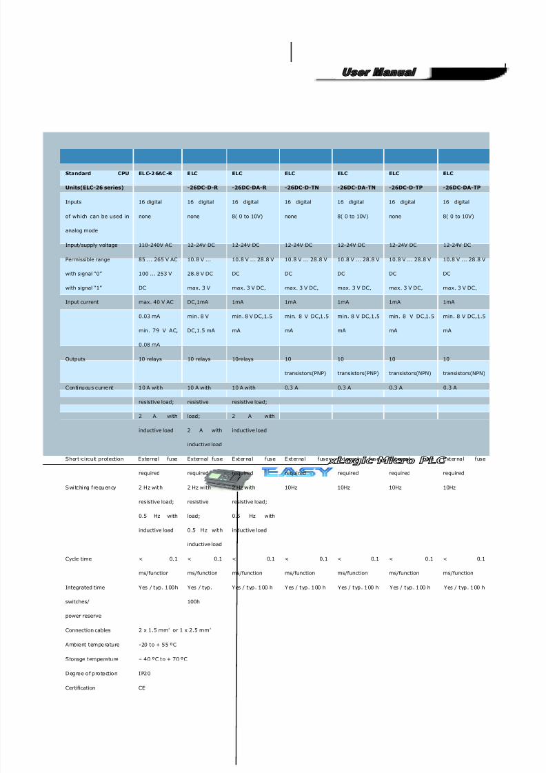
8/20/2019 XLogic User's Manual2
http://slidepdf.com/reader/full/xlogic-users-manual2 332/338
332
Standard CPU
Units(ELC-26 series)
EL C-2 6AC -R E LC
-26DC-D-R
ELC
-26DC-DA-R
ELC
-26DC-D-TN
ELC
-26DC-DA-TN
ELC
-26DC-D-TP
ELC
-26DC-DA-TP
Inputs 16 digital 16 digital 16 digital 16 digital 16 digital 16 digital 16 digital
of which can be used in
analog mode
none none 8( 0 to 10V) none 8( 0 to 10V) none 8( 0 to 10V)
Input/supply voltage 110-240V AC 12-24V DC 12-24V DC 12-24V DC 12-24V DC 12-24V DC 12-24V DC
Permissible range
with signal “0”
with signal “1”
Input current
85 ... 265 V AC
100 ... 253 V
DC
max. 40 V AC
0.03 mA
min. 79 V AC,
0.08 mA
10.8 V ...
28.8 V DC
max. 3 V
DC,1mA
min. 8 V
DC,1.5 mA
10.8 V ... 28.8 V
DC
max. 3 V DC,
1mA
min. 8 V DC,1.5
mA
10.8 V ... 28.8 V
DC
max. 3 V DC,
1mA
min. 8 V DC,1.5
mA
10.8 V ... 28.8 V
DC
max. 3 V DC,
1mA
min. 8 V DC,1.5
mA
10.8 V ... 28.8 V
DC
max. 3 V DC,
1mA
min. 8 V DC,1.5
mA
10.8 V ... 28.8 V
DC
max. 3 V DC,
1mA
min. 8 V DC,1.5
mA
Outputs 10 relays 10 relays 10relays 10
transistors(PNP)
10
transistors(PNP)
10
transistors(NPN)
10
transistors(NPN)
Con ti nu ou s current 10 A w it h
resistive load;
2 A with
inductive load
10 A with
resistive
load;
2 A with
inductive load
10 A with
resistive load;
2 A with
inductive load
0.3 A 0.3 A 0.3 A 0.3 A
Short-circuit protection External fuse
required
External fuse
required
E xt ernal fuse
required
E xt ernal fuse
required
External fuse
required
E xt ernal fuse
required
External fuse
required
Swi tchi ng frequ en cy 2 H z w it h
resistive load;
0.5 Hz with
inductive load
2 Hz with
resistive
load;
0.5 H z w it h
inductive load
2 Hz with
resistive load;
0.5 Hz with
inductive load
10Hz 10Hz 10Hz 10Hz
Cycle time < 0.1
ms/function
< 0.1
ms/function
< 0.1
ms/function
< 0.1
ms/function
< 0.1
ms/function
< 0.1
ms/function
< 0.1
ms/function
Integrated time
switches/
power reserve
Yes / typ. 100h Yes / typ.
100h
Yes / t yp. 100 h Yes / t yp. 100 h Yes / t yp. 100 h Yes / t yp. 100 h Yes / t yp. 100 h
Connection cables 2 x 1.5 mm² or 1 x 2.5 mm²
Ambient temperature -20 to + 55 ºC
Storage temperature – 40 ºC to + 70 ºC
D egree o f pro tect io n I P20
Certification CE
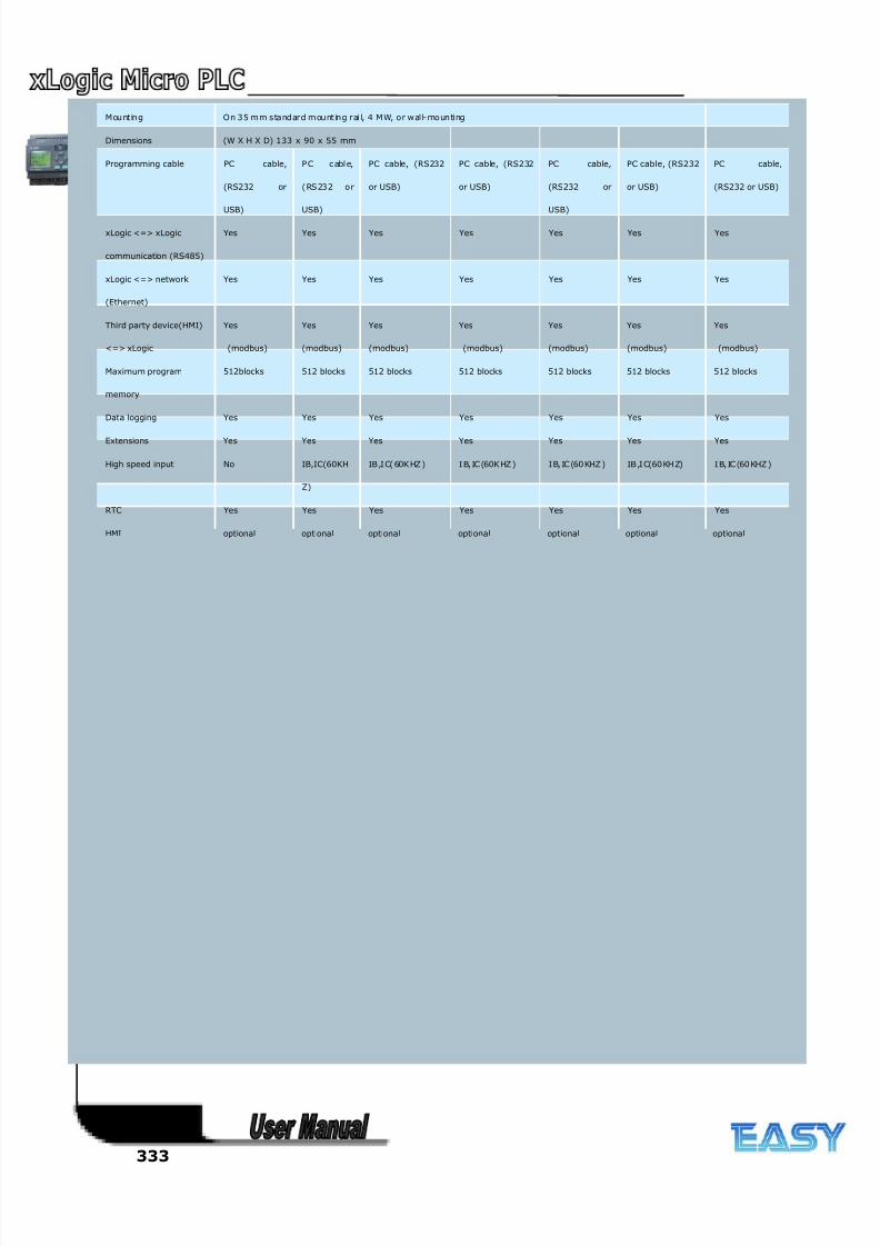
8/20/2019 XLogic User's Manual2
http://slidepdf.com/reader/full/xlogic-users-manual2 333/338
333
M ou nt in g On 35 mm standard mou nt in g rai l, 4 M W, o r w al l-mo un ti ng
Dimensions (W X H X D) 133 x 90 x 55 mm
Programming cable PC cable,
(RS232 or
USB)
P C c abl e,
(RS232 o r
USB)
PC cable, (RS232
or USB)
PC cable, (RS232
or USB)
PC cable,
(RS232 or
USB)
PC cable, (RS232
or USB)
PC cable,
(RS232 or USB)
xLogic <=> xLogic
communication (RS485)
Yes Yes Yes Yes Yes Yes Yes
xLogic <=> network
(Ethernet)
Yes Yes Yes Yes Yes Yes Yes
Third party device(HMI)
<=> xLogic
Yes
(modbus)
Yes
(modbus)
Yes
(modbus)
Yes
(modbus)
Yes
(modbus)
Yes
(modbus)
Yes
(modbus)
Maximum program
memory
512blocks 512 blocks 512 blocks 512 blocks 512 blocks 512 blocks 512 blocks
Data logging Yes Yes Yes Yes Yes Yes Yes
Extensions Yes Yes Yes Yes Yes Yes Yes
High speed input No IB,IC(60KH
Z)
IB ,I C( 60K HZ ) I B, IC (60K HZ ) I B, IC (60 KHZ ) IB ,I C(60 KH Z) I B, IC (60 KHZ )
RTC Yes Yes Yes Yes Yes Yes Yes
HMI optional optional optional optional optional optional optional
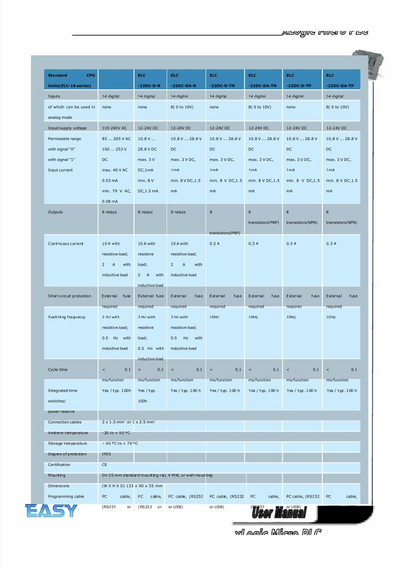
8/20/2019 XLogic User's Manual2
http://slidepdf.com/reader/full/xlogic-users-manual2 334/338
334
Standard CPU
Units(ELC-18 series)
ELC
-22DC-D-R
ELC
-22DC-DA-R
ELC
-22DC-D-TN
ELC
-22DC-DA-TN
ELC
-22DC-D-TP
ELC
-22DC-DA-TP
Inputs 14 digital 14 digital 14 digital 14 digital 14 digital 14 digital 14 digital
of which can be used in
analog mode
none none 8( 0 to 10V) none 8( 0 to 10V) none 8( 0 to 10V)
Input/supply voltage 110-240V AC 12-24V DC 12-24V DC 12-24V DC 12-24V DC 12-24V DC 12-24V DC
Permissible range
with signal “0”
with signal “1”
Input current
85 ... 265 V AC
100 ... 253 V
DC
max. 40 V AC
0.03 mA
min. 79 V AC,
0.08 mA
10.8 V ...
28.8 V DC
max. 3 V
DC,1mA
min. 8 V
DC,1.5 mA
10.8 V ... 28.8 V
DC
max. 3 V DC,
1mA
min. 8 V DC,1.5
mA
10.8 V ... 28.8 V
DC
max. 3 V DC,
1mA
min. 8 V DC,1.5
mA
10.8 V ... 28.8 V
DC
max. 3 V DC,
1mA
min. 8 V DC,1.5
mA
10.8 V ... 28.8 V
DC
max. 3 V DC,
1mA
min. 8 V DC,1.5
mA
10.8 V ... 28.8 V
DC
max. 3 V DC,
1mA
min. 8 V DC,1.5
mA
Outputs 8 relays 8 relays 8 relays 8
transistors(PNP)
8
transistors(PNP)
8
transistors(NPN)
8
transistors(NPN)
Con ti nu ou s current 10 A w it h
resistive load;
2 A with
inductive load
10 A with
resistive
load;
2 A with
inductive load
10 A with
resistive load;
2 A with
inductive load
0.3 A 0.3 A 0.3 A 0.3 A
Short-circuit protection External fuse
required
External fuse
required
E xt ernal fuse
required
E xt ernal fuse
required
External fuse
required
E xt ernal fuse
required
External fuse
required
Swi tchi ng frequ en cy 2 H z w it h
resistive load;
0.5 Hz with
inductive load
2 Hz with
resistive
load;
0.5 H z w it h
inductive load
2 Hz with
resistive load;
0.5 Hz with
inductive load
10Hz 10Hz 10Hz 10Hz
Cycle time < 0.1
ms/function
< 0.1
ms/function
< 0.1
ms/function
< 0.1
ms/function
< 0.1
ms/function
< 0.1
ms/function
< 0.1
ms/function
Integrated time
switches/
power reserve
Yes / typ. 100h Yes / typ.
100h
Yes / t yp. 100 h Yes / t yp. 100 h Yes / t yp. 100 h Yes / t yp. 100 h Yes / t yp. 100 h
Connection cables 2 x 1.5 mm² or 1 x 2.5 mm²
Ambient temperature -20 to + 55 ºC
Storage temperature – 40 ºC to + 70 ºC
D egree o f pro tect io n I P20
Certification CE
M ou nt in g On 35 mm standard mou nt in g rai l, 4 M W, o r w al l-mo un ti ng
Dimensions (W X H X D) 133 x 90 x 55 mm
Programming cable PC cable,
(RS232 or
P C c abl e,
(RS232 o r
PC cable, (RS232
or USB)
PC cable, (RS232
or USB)
PC cable,
(RS232 or
PC cable, (RS232
or USB)
PC cable,
(RS232 or USB)
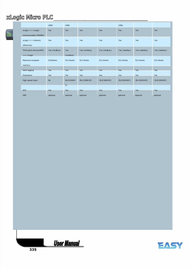
8/20/2019 XLogic User's Manual2
http://slidepdf.com/reader/full/xlogic-users-manual2 335/338
335
USB) USB) USB)
xLogic <=> xLogic
communication (RS485)
Yes Yes Yes Yes Yes Yes Yes
xLogic <=> network
(Ethernet)
Yes Yes Yes Yes Yes Yes Yes
Third party device(HMI)
<=> xLogic
Yes (mo dbus) Yes
(modbus)
Y es ( mo db us ) Y es ( mo db us ) Y es ( mod bus ) Y es ( mod bus ) Y es ( mod bus )
Maximum program
memory
512blocks 512 blocks 512 blocks 512 blocks 512 blocks 512 blocks 512 blocks
Data logging Yes Yes Yes Yes Yes Yes Yes
Extensions Yes Yes Yes Yes Yes Yes Yes
High speed input No IB,IC(60KH
Z)
IB ,I C( 60K HZ ) I B, IC (60K HZ ) I B, IC (60 KHZ ) IB ,I C(60 KH Z) I B, IC (60 KHZ )
RTC Yes Yes Yes Yes Yes Yes Yes
HMI optional optional optional optional optional optional optional
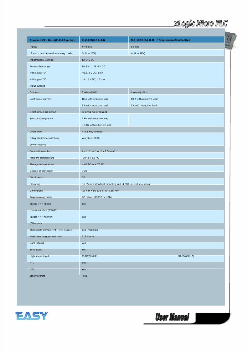
8/20/2019 XLogic User's Manual2
http://slidepdf.com/reader/full/xlogic-users-manual2 336/338
336
Standard CPU Units(ELC-22 series) ELC-22DC-DA-R-N ELC-12DC-DA-R-N Program in eSmsConfig)
Inputs 14 digital 8 digital
of which can be used in analog mode 8( 0 to 10V) 4( 0 to 10V)
Input/supply voltage 12-24V DC
Permissible range
with signal “0”
with signal “1”
Input current
10.8 V ... 28.8 V DC
max. 3 V DC, 1mA
min. 8 V DC,1.5 mA
Outputs 8 relays(10A) 4 relays(10A)
Continuous current 10 A with resistive load;
2 A with inductive load
10 A with resistive load;
2 A with inductive load
S hor t- cir cu it p ro te ction Ex te rn al f us e r eq uir ed
Switching frequency 2 Hz with resistive load;
0.5 Hz with inductive load
Cycle time < 0.1 ms/function
Integrated time switches/
power reserve
Yes / typ. 100h
Connection cables 2 x 1.5 mm² or 1 x 2.5 mm²
Ambient temperature -20 to + 55 ºC
Storage temperature – 40 ºC to + 70 ºC
Degree of protection IP20
Certification CE
Mounting On 35 mm standard mounting rail, 4 MW, or wall-mounting
Dimensions (W X H X D) 133 x 90 x 55 mm
Programming cable PC cable, (RS232 or USB)
xLogic <=> xLogic
communication (RS485)
Yes
xLogic <=> network
(Ethernet)
Yes
Third party device(HMI) <=> xLogic Yes (modbus)
Maximum program memory 512 blocks
Data logging Yes
Extensions Yes
High speed input IB,IC(60KHZ) IB,IC(60KHZ)
RTC Yes
HMI Yes
Ethernet Port Yes
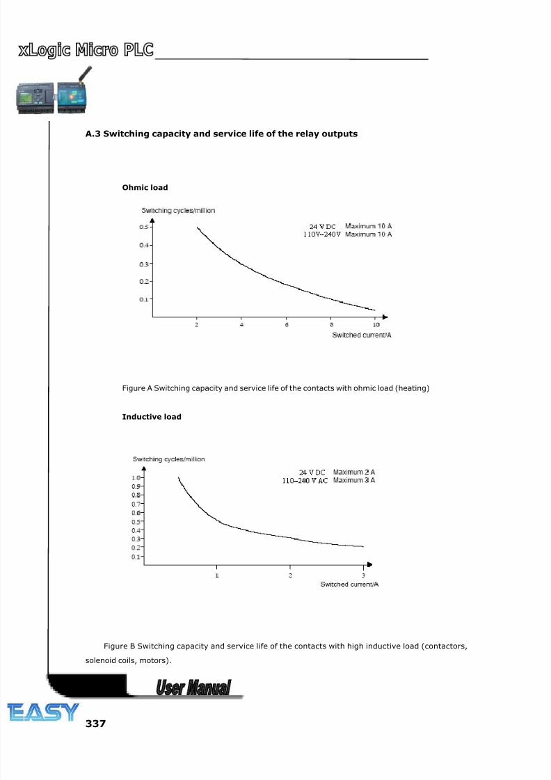
8/20/2019 XLogic User's Manual2
http://slidepdf.com/reader/full/xlogic-users-manual2 337/338
337
A.3 Switching capacity and service life of the relay outputs
Ohmic load
Figure A Switching capacity and service life of the contacts with ohmic load (heating)
Inductive load
Figure B Switching capacity and service life of the contacts with high inductive load (contactors,
solenoid coils, motors).
8/20/2019 XLogic User's Manual2
http://slidepdf.com/reader/full/xlogic-users-manual2 338/338
338
REVISION RECORD
Revision Description
2013.1.25 6.5.18.1 How to change parameters of blocks in displayed message ? had been added.
2013.8.1 Changed the naming rules, “-N” means the Ethernet PLC in chapter 2.1
Added “ELC-12DC-DA-R-N, ELC-22DC-DA-R-N” of model selection table in chapter2.2
Added the structure and dimensions about “ELC-12DC-DA-R-N, ELC-22DC-DA-R-N” in chapter2.3
Added below new function blocks
6.5.38 Word to Bit
6.5.39 Bit to Word
6.5.40 Stopwatch
6.5.41 Analog filter
6.5.43 Average value
6.5.44 Device Reset
6.5.45 Comport Status
Added configuration about Ethernet PLC
Chapter 7 How to configure the Ethernet modem built-in CPU ?
7.1 Configuration with DeviceManager
7.2 Establish communication between CPU and xLogicSoft/SCADA via Ethernet
7.3 How to establish the communication among CPUs via Ethernet ?
Added the technical data about Ethernet PLC in chapter A.2 Technical data: xLogic
2013.8.10 Added new function block
6.5.46Astronomical clock