XLogic Alpha Link
38
XLogi c Alpha-Lin k A X / MADI–AX / MADI-SX Installation and User Guide XLogic Alpha-Link. This is SSL.
-
Upload
dreamkatcher -
Category
Documents
-
view
224 -
download
0
Transcript of XLogic Alpha Link

8/8/2019 XLogic Alpha Link
http://slidepdf.com/reader/full/xlogic-alpha-link 1/40
XLogic Alpha-Link A
X / MADI–AX / MADI-SX
Installation and User Guide
XLogic Alpha-Link. This is SSL.

8/8/2019 XLogic Alpha Link
http://slidepdf.com/reader/full/xlogic-alpha-link 2/40
8/8/2019 XLogic Alpha Link
http://slidepdf.com/reader/full/xlogic-alpha-link 3/40
Safety and Installation Considerations 1
1. Introduction 3
2. Installation 5
Master Clock 7
3. Audio Connectivity 9
Overview 9
ADAT Inputs and Outputs 9
AES/EBU Inputs and Outputs 10
Analogue Inputs and Outputs 11
MADI Ports 12
Expansion Bus Port 12
MIDI Connectivity 12
4. Front Panel 13
Power Switch 13
Headphone Socket 13
Routing Matrix 14
Sample Rate Button and Sample Rate Indicator LEDs 17
Meter Section 18
5. System Settings and Diagnostic Mode 19
Overview 19
Selecting a Virtual 8-way Option Switch 19
Selecting an Option 19
Setting an Option 19
5.1 Firmware Version 20
Firmware Version Number 20
5.2 ADAT Compatible Alpha-Link Units 22
Option Switch 1 22
Option Switch 2 24
5.3 AES/EBU Compatible Alpha-Link Units 25
Option Switch 1 25
Option Switch 2 27
Appendix A – AES/EBU Interface 29
Appendix B – Interface Frameclock vs WordClock 30
Appendix C – Troubleshooting 33
Appendix D – Specifications 35
Contents

8/8/2019 XLogic Alpha Link
http://slidepdf.com/reader/full/xlogic-alpha-link 4/40
8/8/2019 XLogic Alpha Link
http://slidepdf.com/reader/full/xlogic-alpha-link 5/40
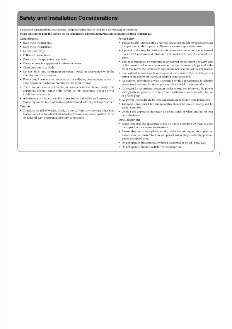
This section contains definitions, warnings, and practical information to ensure a safe working environment.
Please take time to read this section before installing or using this unit. Please do not dispose of these instructions.
Safety and Installation Considerations
General Safety
• Read these instructions.
• Keep these instructions.
• Heed all warnings.
• Follow all instructions.
• Do not use this apparatus near water.
• Do not expose this apparatus to rain or moisture.
• Clean only with dry cloth.
• Do not block any ventilation openings. Install in accordance with themanufacturer’s instructions.
• Do not install near any heat sources such as radiators, heat registers, stoves orother apparatus (including amplifiers) that produce heat.
• There are no user-adjustments, or user-serviceable items, inside thisapparatus. Do not remove the covers of this apparatus; doing so willinvalidate your warranty.
• Adjustments or alterations to this apparatus may affect the performance suchthat safety and/or international compliance standards may no longer be met.
Caution
• To reduce the risk of electric shock, do not perform any servicing other thanthat contained in these Installation Instructions unless you are qualified to doso. Refer all servicing to qualified service personnel.
Power Safety
• This apparatus is fitted with a universal power supply, approved and certifiedfor operation in this apparatus. There are no user-replaceable fuses.
• A power cord is supplied with this unit. Alternative power cords may be usedif rated 2.5A or above and fitted with a 3-pin IEC320 connector and a 3-corecable.
• This apparatus must be connected to an earthed mains outlet. The earth coreof the power cord must always connect to the mains supply ground – theearth core forms the safety earth and should not be removed for any reason.
• If an extension power cable or adaptor is used, ensure that the total powerrating of the power cable and/or adaptor is not exceeded.
• An external disconnect device is required for this apparatus; a detachablepower cord – as used for this apparatus – is a suitable disconnect device.
• An external over-current protection device is required to protect the powerwiring to this apparatus. In certain countries this function is supplied by useof a fused plug.
• All power wiring should be installed according to local wiring regulations.
• The mains outlet used for this apparatus should be located nearby and beeasily accessible.
• Unplug this apparatus during an electrical storm or when unused for longperiods of time.
Installation Notes
• When installing this apparatus, either fix it into a standard 19" rack or placethe apparatus on a secure level surface.
• Ensure that no strain is placed on the cables connecting to this apparatus.Ensure also that such cables are not placed where they can be stepped on,pulled or tripped over.
• Do not operate this apparatus whilst it is covered or boxed in any way.
• Do not operate this unit with the covers removed.
1
8/8/2019 XLogic Alpha Link
http://slidepdf.com/reader/full/xlogic-alpha-link 6/40
2
8/8/2019 XLogic Alpha Link
http://slidepdf.com/reader/full/xlogic-alpha-link 7/40
Congratulations on your purchase of this Solid State Logic Alpha-Link audio I/O solution. Please be assured that it will provide
you with many years of reliable service while delivering the pristine audio quality you expect from any Solid State Logic
product.
The Alpha-Link Audio I/O Product Range is a new collection of highly flexible and fully featured multi-channel audio
converters for Studio, Live and Broadcast Applications with an incredible price/performance ratio. There are three Alpha-Link
models, all featuring high quality 24-channel SSL enhanced AD/DA converter circuitry and offering a choice of digital audio
format options. The Alpha Link MADI SX is a MADI & AES/EBU based converter, whilst the Alpha-Link AX and Alpha-
Link MADI AX are ADAT based converters.
The XLogic Alpha-Link series of Audio Converters are stylishly designed, 2U-high rack-mountable units with deceptively
simple front panel controls. Each unit offers a comprehensive input/output routing matrix which can be used to set up globalconnections between the various I/O connections that makes all combinations possible. There is also a handy front panel
headphone connection plus a meter section for the analogue inputs and outputs with an AD/DA selection button, mode indicator
LEDs and 24 tri-colour level LEDs.
All Alpha-Link units can be used as standalone format converters, but used in combination with an SSL or Soundscape
Mixpander PCI card they provide a powerful, highly flexible IO solution for native PC-based audio workstations. When the
unit is connected to a Mixpander card the inputs and outputs can be routed individually from the PC using the Soundscape Mixer
software.
1. Introduction
3

8/8/2019 XLogic Alpha Link
http://slidepdf.com/reader/full/xlogic-alpha-link 8/40
Designation of Supported Hardware
The information in this manual generally applies to all the models in the XLogic Alpha-Link range: Alpha-Link AX, Alpha-
Link MADI-AX, Alpha-Link MADI-SX and in this manual they are collectively referred to as the “Alpha-Link”. References
to particular audio interfaces (MADI, ADAT, AES/EBU or analogue) apply only to the Alpha-Link models that support this
interface.
IMPORTANT: Please register your XLogic Alpha-Link unit on our website. This will ensure that you receive
notification of future updates and other important information, and that your guarantee is registered. Registration willalso make you eligible for technical support.
The Solid State Logic home page is at: http://www.solid-state-logic.com
From there you can go to the Support page, which includes links to the Product Registration and Download pages. You
can also visit the Frequently Asked Questions (FAQ) area for any questions you might have or to contact tech support.
4

8/8/2019 XLogic Alpha Link
http://slidepdf.com/reader/full/xlogic-alpha-link 9/40
The XLogic Alpha-Link AX/MADI-AX/MADI-SX package includes:
• The Alpha-Link unit• One mains connection cable
• This manual
If required, the Alpha-Link unit can be rack mounted. It occupies 2U of rack space in a standard 19-inch rack.
To use an Alpha-Link unit with an SSL or Soundscape Mixpander PCI audio card, connect the Expansion Bus port of the
Alpha-Link unit to the Expansion Bus port of the Mixpander card using a Mixpander Expansion Bus cable.
WARNING !Always switch the host computer and the Alpha-Link unit off before connecting or
disconnecting the Mixpander Expansion Bus cable or damage may result.
2. Installation
5

8/8/2019 XLogic Alpha Link
http://slidepdf.com/reader/full/xlogic-alpha-link 10/40
6
Alpha-Link MADI-SX Rear Panel
Expansion Bus Port AES/EBU Ports A, B and C IEC Connector
• Connect the mains cable to the IEC connector of the Alpha-Link unit.
• Audio sources and other devices may be connected now to the various inputs and outputs.
• If connecting to a Mixpander card:
Power up the computer that hosts the Mixpander card and start the Soundscape Mixer software.• Power up the Alpha-Link unit using the On/Off switch on the front panel.
• Select a Master Clock setting as described in the “Master Clock” section on page 7.
8/8/2019 XLogic Alpha Link
http://slidepdf.com/reader/full/xlogic-alpha-link 11/40
7
Master Clock
The Alpha-Link unit can operate as a Clock Master device (“Internal” mode), or as a Clock Slave device locked to a Master
Clock signal received either via its WordClock input (“External” mode) or via a digital audio connection (“ADAT” or
“AES/EBU” mode).
NOTE: At any given time, only one of the ADAT ports or one of the AES/EBU inputs (on port A) can be used to receive and
lock to a Master Clock signal. The required ADAT port or AES/EBU input can be selected for that purpose from the front
panel by following the procedure described in the “System Settings” chapter.
WordClock Input WordClock Output
AES/EBU Ports A, B &C
(or location of ADAT ports, depending on model)
When the Alpha-Link unit is used as part of a Mixpander setup, the Master Clock mode must be selected in the Soundscape
Mixer software. In other cases, pressing the front panel Clock button repeatedly will cycle through the available Master Clock
modes.

8/8/2019 XLogic Alpha Link
http://slidepdf.com/reader/full/xlogic-alpha-link 12/40
8
The currently selected mode is indicated by illumination of the corresponding LED. Shown in the example below, the AES mode
has been selected for an Alpha-Link MADI-SX.
A flashing LED indicates that the corresponding mode is selected but the Alpha-Link is not
receiving a valid Master Clock signal via the selected port/input.
NOTE: The Mixpander card only operates as a Master Clock Slave. Therefore, if the Alpha-
Link is used with a Mixpander connected to its Expansion Bus port, it must provide a Master
Clock signal to the Mixpander. This may be the Alpha-Link’s Internal Master Clock or a
ADAT, AES/EBU or External Master Clock.
Once locked to an ADAT, AES/EBU, Internal or External Master Clock signal, the Alpha-Link distributes that signal through its ADAT, AES/EBU, WordClock output and Expansion
Bus ports.
AES mode
selected
Clock button

8/8/2019 XLogic Alpha Link
http://slidepdf.com/reader/full/xlogic-alpha-link 13/40
9
Overview
All Alpha-Link models feature 24 channels of SSL grade analogue I/O, an Expansion Bus port and a stereo headphone output.
• Alpha-Link MADI-SX converts analogue I/O to and from MADI & AES/EBU
• Alpha-Link MADI-AX converts analogue I/O to and from MADI & ADAT
• Alpha-Link AX converts he analogue I/O to and from ADAT
All the audio connectors are located on the rear panel of the unit, except for the headphone output which is on the front.
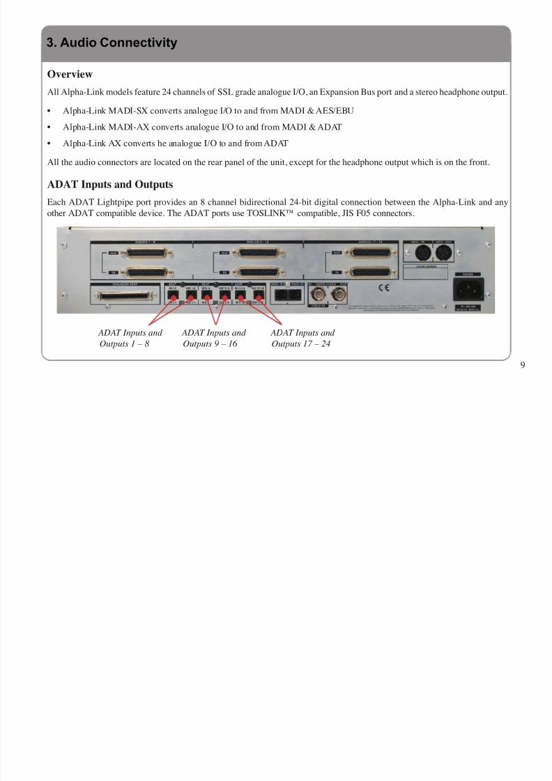
ADAT Inputs and Outputs
Each ADAT Lightpipe port provides an 8 channel bidirectional 24-bit digital connection between the Alpha-Link and any
other ADAT compatible device. The ADAT ports use TOSLINK™ compatible, JIS F05 connectors.
ADAT Inputs and ADAT Inputs and ADAT Inputs and
Outputs 1 – 8 Outputs 9 – 16 Outputs 17 – 24
3. Audio Connectivity

8/8/2019 XLogic Alpha Link
http://slidepdf.com/reader/full/xlogic-alpha-link 14/40
AES/EBU Inputs and Outputs
The AES/EBU inputs and outputs are available via three
25-pin ‘D’ type connectors wired according to the DB25
AES/EBU digital I/O specification. Each connector provides
four stereo inputs and outputs (eight input channels and eight
output channels).
AES/EBU Connections
Shown Right:
AES/EBU Connections I/O 1 – 8 *
Location: Rear Panel
Connector Type: 25-pin ‘D’ Type Female
* I/O 9 – 16 and I/O 17 – 24 similar
Pin Description
1 Channel 1&2 IN (+ve)
14 Channel 1&2 IN (–ve)2 Channel 3&4 IN (+ve)
15 Channel 3&4 IN (–ve)
3 Channel 5&6 IN (+ve)
16 Channel 5&6 IN (–ve)
4 Channel 7&8 IN (+ve)
17 Channel 7&8 IN (–ve)
5 Channel 1&2 OUT (+ve)
18 Channel 1&2 OUT (–ve)
6 Channel 3&4 OUT (+ve)19 Channel 3&4 OUT (–ve)
7 Channel 5&6 OUT (+ve)
20 Channel 5&6 OUT (–ve)
8 Channel 7&8 OUT (+ve)
21 Channel 7&8 OUT (–ve)
9 n/c
22 0V
10 0V
23 n/c11 n/c
24 0V
12 0V
25 0V
13 0V
10
8/8/2019 XLogic Alpha Link
http://slidepdf.com/reader/full/xlogic-alpha-link 15/40
Analogue Inputs and Outputs
The analogue inputs and outputs are available via six 25-pin
‘D’ type connectors wired according to the Tascam DB25 I/O
specification. Each connector provides eight inputs or outputs.
Outputs 1 – 8 Outputs 9 – 16 Outputs 17 – 24
Inputs 1 – 8 Inputs 9 – 16 Inputs17 – 24
Shown Right:
Analogue Connections I/O 1 – 8 *
Location: Rear PanelConnector Type: 25-pin ‘D’ Type Female
* I/O 9 – 16 and I/O 17 – 24 similar
Pin Description
1 Channel 8 (+ve)
14 Channel 8 (–ve)2 0V
15 Channel 7 (+ve)
3 Channel 7 (–ve)
16 0V
4 Channel 6 (+ve)
17 Channel 6 (–ve)
5 0V
18 Channel 5 (+ve)
6 Channel 5 (-ve)19 0V
7 Channel 4 (+ve)
20 Channel 4 (–ve)
8 0V
21 Channel 3 (+ve)
9 Channel 3 (-ve)
22 0V
10 Channel 2 (+ve)
23 Channel 2 (-ve)
11 0V
24 Channel 1 (+ve)
12 Channel 1 (-ve)
25 0V
13 n/c
11

8/8/2019 XLogic Alpha Link
http://slidepdf.com/reader/full/xlogic-alpha-link 16/40
MADI Ports
The MADI interface supports both the “legacy frame
pattern” and “96kHz frame pattern” when operating at
double speed (96kHz). Please refer to the AES10-2003
document for details. The legacy frame pattern should be
viewed as an SMUX2 signal (refer to the Appendix for
further details).
Expansion Bus Port MADI Output Port MADI Input Port
Expansion Bus Port
The Expansion Bus port can be used to connect the Alpha-Link to an SSL or Soundscape Mixpander PCI audio card. It provides
a high-speed bidirectional 64-channel connection between the Alpha-Link and the Mixpander card.
The Soundscape Expansion Bus is proprietary and the connection between the Mixpander card and Alpha-Link must be made
using an Expansion Bus cable supplied by Solid State Logic. The cables supplied by Solid State Logic are made to the
maximum length allowing proper operation.
MIDI Connectivity
All Alpha-Link models feature MIDI input and output ports. At the time of writing, the functionality of these ports has not been
implemented, but future software updates might add specific MIDI functionality.
12
8/8/2019 XLogic Alpha Link
http://slidepdf.com/reader/full/xlogic-alpha-link 17/40
13
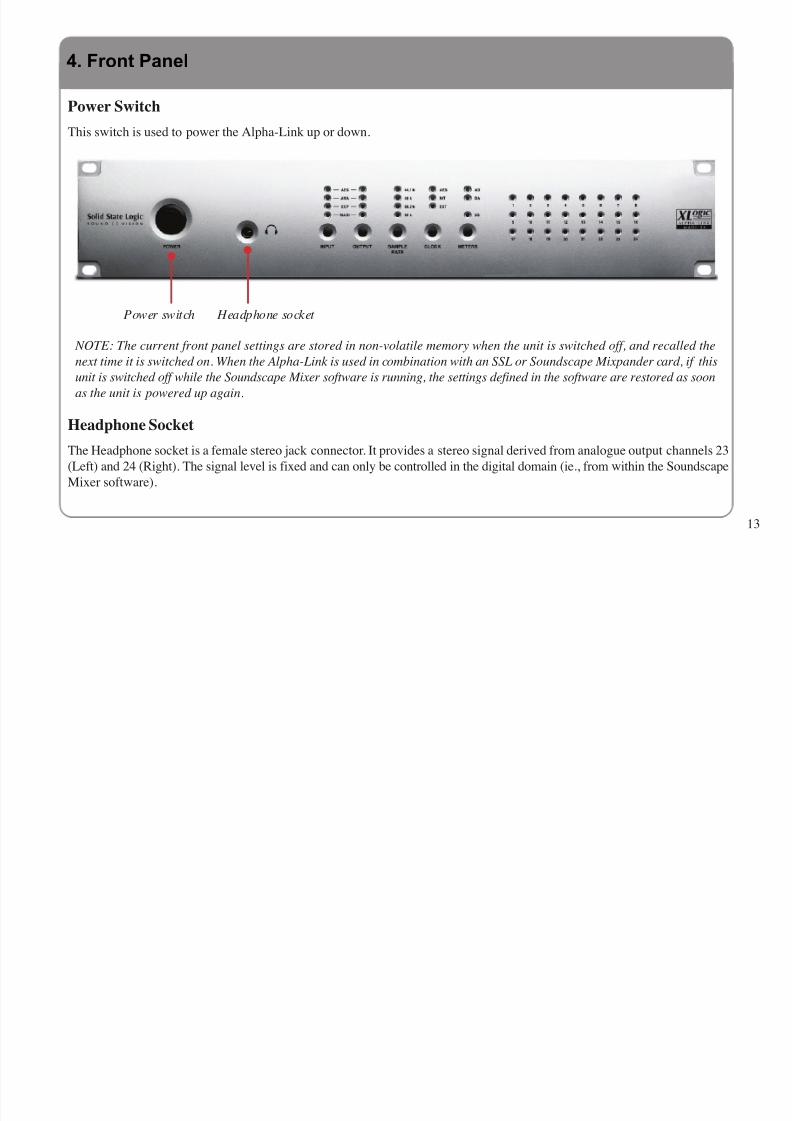
Power Switch
This switch is used to power the Alpha-Link up or down.
Power switch Headphone socket
NOTE: The current front panel settings are stored in non-volatile memory when the unit is switched off, and recalled the
next time it is switched on. When the Alpha-Link is used in combination with an SSL or Soundscape Mixpander card, if this
unit is switched off while the Soundscape Mixer software is running, the settings defined in the software are restored as soon
as the unit is powered up again.
Headphone Socket
The Headphone socket is a female stereo jack connector. It provides a stereo signal derived from analogue output channels 23
(Left) and 24 (Right). The signal level is fixed and can only be controlled in the digital domain (ie., from within the Soundscape
Mixer software).
4. Front Panel
8/8/2019 XLogic Alpha Link
http://slidepdf.com/reader/full/xlogic-alpha-link 18/40
Routing Matrix
The Alpha-Link unit can be used as a standalone format converter for any piece of equipment that supports one of its formats.
The Alpha-Link routing matrix includes one Input button and one Output button, four Input indicator LEDs and four Output
indicator LEDs. It can be used to connect any input group (ie., the ADAT, AES/EBU, Analogue, Expansion Bus or MADI
inputs) to any output group. The picture below shows the routing matrix for an Alpha-Link MADI-SX:
Alternatively, the Alpha-Link can be connected to an SSL or Soundscape Mixpander/9 or Mixpander/5 via its Expansion Busport. In that case it can act as multi-channel bidirectional format converter between the MADI, ADAT, AES/EBU or analogue
inputs and outputs and the Expansion Bus (depending on model). The routing is determined in the Soundscape Mixer software
and the front panel routing matrix is deactivated.
AES input LED
Analogue input LED
Expansion input LED
MADI input LED
Input button
AES output LED
Analogue input LED
Expansion output LED
MADI output LED
Output button
14

8/8/2019 XLogic Alpha Link
http://slidepdf.com/reader/full/xlogic-alpha-link 19/40
The routing connections are 24-bit digital switches that do not affect the quality of the signal or the integrity of the audio data
in any way.
Pressing the Output button repeatedly will cycle through the available output groups. The currently selected output group is
indicated by illumination of the corresponding LED. The LEDs of the input column will indicate which input group(s) are
connected to the selected output group.
In order to change the input group(s) connected to a given output group, press the Output button and hold it down when the
required output group is selected. Pressing the Input button repeatedly while the Output button is held down will cycle through
the input groups available for that output. Releasing the Output button when the input LEDs indicate the required Input group
selection will store and activate that selection.
NOTE: Pressing the Input button alone has no effect. The Input button only works in combination with the Output button.
15

8/8/2019 XLogic Alpha Link
http://slidepdf.com/reader/full/xlogic-alpha-link 20/40
16
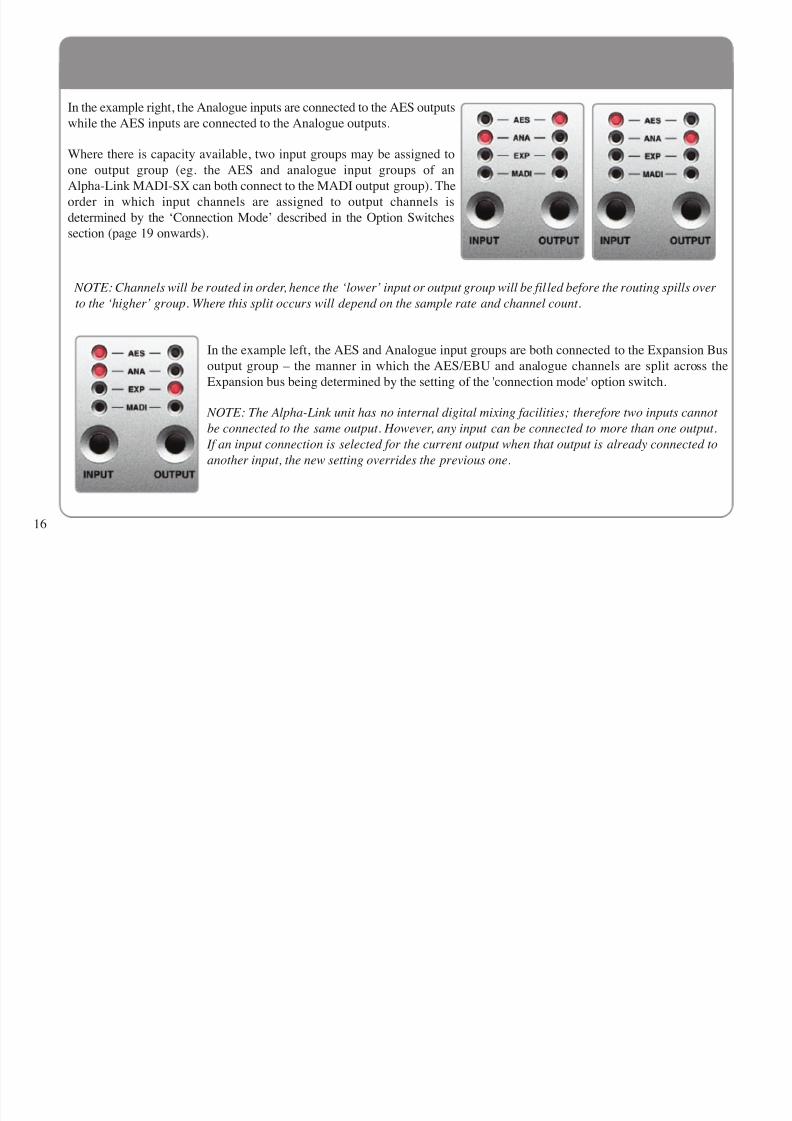
In the example right, the Analogue inputs are connected to the AES outputs
while the AES inputs are connected to the Analogue outputs.
Where there is capacity available, two input groups may be assigned to
one output group (eg. the AES and analogue input groups of an
Alpha-Link MADI-SX can both connect to the MADI output group). The
order in which input channels are assigned to output channels is
determined by the ‘Connection Mode’ described in the Option Switches
section (page 19 onwards).
NOTE: Channels will be routed in order, hence the ‘lower’ input or output group will be filled before the routing spills over
to the ‘higher’ group. Where this split occurs will depend on the sample rate and channel count.
In the example left, the AES and Analogue input groups are both connected to the Expansion Bus
output group – the manner in which the AES/EBU and analogue channels are split across the
Expansion bus being determined by the setting of the 'connection mode' option switch.
NOTE: The Alpha-Link unit has no internal digital mixing facilities; therefore two inputs cannot
be connected to the same output. However, any input can be connected to more than one output.
If an input connection is selected for the current output when that output is already connected to
another input, the new setting overrides the previous one.

8/8/2019 XLogic Alpha Link
http://slidepdf.com/reader/full/xlogic-alpha-link 21/40
17
Sample Rate Button and Sample Rate Indicator LEDs
When the Alpha-Link is used in combination with a Mixpander card the Sample Rate button is deactivated.
The Sample Rate indicator LEDs reflect the settings made in the Soundscape Mixer software.
In all other cases, when the Clock source is set to Internal (as described in the ‘Master Clock’ section on
page 7), pressing the Sample Rate button repeatedly will cycle through the available Sample Rates: 44.1kHz,
48kHz, 88.2kHz and 96kHz. The current sample rate selection is indicated by illumination of the
corresponding LED.
When the Master Clock source is ADAT, AES/EBU or External, the illuminated LED indicates the received
Sample Rate. If there is an error or the received Sample Rate does not fall within the tolerances that are
normally expected, all the LEDs will be off.
Sample Rate button
If pressing the Sample Rate button has no effect, check that the Master Clock is set to Internal, as described in the ‘Master Clock’
section on page 7.

8/8/2019 XLogic Alpha Link
http://slidepdf.com/reader/full/xlogic-alpha-link 22/40
Meter Section
The meter section includes the Meters button, the AD and DA indicator LEDs and twenty four metering LEDs. For Alpha-Link
units that have analogue connectivity, it allows the level of the signals received via the analogue inputs or transmitted via theanalogue ouputs to be monitored.
AD Indicator LED
DA Indicator LED
NOTE: While the XS LED is
located in the same area of
the front panel, it is not used
for metering. Its function is
described in the “System
Settings” chapter.
Pressing the Meters button switches the monitoring mode between AD (monitoring the level of the signal received via the
analogue inputs) and DA (showing the level of the signal transmitted via the analogue outputs). For each analogue input or
output channel, the signal level is represented by the state of the LED with the corresponding number. The LEDs respond to
the signal level in the digital domain as follows:
• Below –30dB FS (< –8dBu applied to an analogue input): the LED is OFF.
• Above –30dB FS (> –8dBu applied to an analogue input): the LED is GREEN.
• Above –3.0dB FS (> +19dBu applied to an analogue input): the LED is AMBER.
• Above –0.1dB FS (> +22dBu applied to an analogue input): the LED is RED.
18
Metering LEDs.
Channel 13 is clipping in
this example and would be
indicated by a red LED.
8/8/2019 XLogic Alpha Link
http://slidepdf.com/reader/full/xlogic-alpha-link 23/40
19
Overview
Two virtual 8-way Option Switches allow global system parameters to be set as required. These switches are controlled from
the front panel when the Alpha-Link is in Diagnostic mode; holding the Sample Rate and Clock buttons for at least 1.5 secondsduring power up will cause the Alpha-Link to start in this mode which will be indicated by a flashing XS LED (see over leaf).
Selecting a Virtual 8-way Option Switch
When the Alpha-Link is in diagnostic mode, pressing the Meters button toggles between Option Switch 1 (indicated by a lit
amber channel 17 LED) and Option Switch 2 (indicated by a lit amber channel 18 LED).
Selecting an Option
When an Option Switch is selected, pressing the Output button cycles between up to eight options available for that switch.
The current option selection is indicated by a lit red LED in the second row of metering LEDs. A lit channel 9 LED indicates
that option 1 is selected; a lit channel 10 LED indicates that option 2 is selected, and so on.
Setting an Option
When an option is selected, pressing the Input button toggles it between two possible settings. The current setting is indicated
by the on/off status of the corresponding LED in the first row of metering LEDs. The setting of option 1 is indicated by the
on/off status of the channel 1 LED, the setting of option 2 is indicated by the on/off status of the channel 2 LED, and so on.
Please refer to the following ‘Option Switch 1’ and ‘Option Switch 2’ tables for details of the available options and settings.
Note also that different tables are provided for ADAT compatible and AES/EBU compatible Alpha-Link units.
5. System Settings and Diagnostic Mode

8/8/2019 XLogic Alpha Link
http://slidepdf.com/reader/full/xlogic-alpha-link 24/40
20
Firmware Version Number
If the Alpha-Link unit is started in Diagnostic mode, the firmware varsion can be checked:
Flashing XS LED
Pressing the Sample Rate and Clock buttons simultaneously will cause the Alpha-
Link to display its firmware version number using the top row of meter LEDs until
the buttons are released. The unit then returns to normal operation.
The firmware version number is expressed in binary. Each LED can represent a “0”
(LED off) or a “1” (LED on). LEDs 1 to 4 represent the first nibble (the numberbefore the point) and LEDs 5 to 8 represent the second nibble (the number after the
point).
Sample Rate button Clock button
5.1 Firmware Version

8/8/2019 XLogic Alpha Link
http://slidepdf.com/reader/full/xlogic-alpha-link 25/40
21
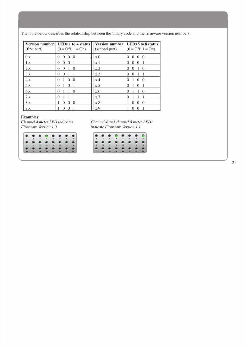
The table below describes the relationship between the binary code and the firmware version numbers.
Examples:
Channel 4 meter LED indicates Channel 4 and channel 8 meter LEDs
Firmware Version 1.0 indicate Firmware Version 1.1
Version number(first part)
LEDs 1 to 4 status(0 = Off, 1 = On)
Version number(second part)
LEDs 5 to 8 status(0 = Off, 1 = On)
0.x 0 0 0 0 x.0 0 0 0 0
1.x 0 0 0 1 x.1 0 0 0 1
2.x 0 0 1 0 x.2 0 0 1 0
3.x 0 0 1 1 x.3 0 0 1 1
4.x 0 1 0 0 x.4 0 1 0 0
5.x 0 1 0 1 x.5 0 1 0 1
6.x 0 1 1 0 x.6 0 1 1 0
7.x 0 1 1 1 x.7 0 1 1 1
8.x 1 0 0 0 x.8 1 0 0 0
9.x 1 0 0 1 x.9 1 0 0 1

8/8/2019 XLogic Alpha Link
http://slidepdf.com/reader/full/xlogic-alpha-link 26/40
22
Option Switch 1
Option Switch 1 (Indicated by a lit amber Channel 17 LED)(Default settings in bold)
LED number Option Setting LED status
1 MADI – number of channels64(32) Off
56(28) On
2 MADI – 96kHz mode*3Non-SMUX2 Off
SMUX2 On
3 ADAT – 96kHz mode*3
Non-SMUX2 Off
SMUX2 On
4 Analogue or ADAT connection mode*1ANA lowest Off
ADAT lowest On
5 ADAT – Channel Status*2Use Off
Ignore On
6 WordClock IN – 96kHz mode*3WordClock Off
FrameClock On
7 WordClock OUT – 96kHz mode*4 WordClock Off
FrameClock On
8 FrameClock OUT – Phase Angle*50° Off
90° On
5.2 ADAT Compatible Alpha-Link Units
8/8/2019 XLogic Alpha Link
http://slidepdf.com/reader/full/xlogic-alpha-link 27/40
23
*1 Analogue or ADAT connection mode: When the analogue and ADAT input groups are both connected to the MADI output
group, this option determines which input group feeds the MADI output group first and hence affects the order in which input
channels are assigned to channels in the MADI stream. Similarly, when the MADI input group is routed to both the analogue
and ADAT output groups, this switch also determines the order in which the MADI channels are split across the selected output
groups.
*2 ADAT Channel Status: Newer ADAT interfaces can identify the sample rate range (eg. as used in the Alesis HD24).
*3 SMUX2/non-SMUX2: With an SMUX2 data-format, the Sample Rate cannot be predicted. These option switches thereforeserve a double purpose:
• If the unit has to lock from the ADAT/MADI, these option switches set how the interface-embedded WordClock is
interpreted when this clock is below 57kHz.Non-SMUX2 = ‘normal’ sample frequency
SMUX2 = ‘double’ sample frequency
• If the unit does not have to lock from the interface, these option switches set which data-format has to be used for thegeneration of the higher sample-rate-signal.
Non-SMUX2 = ‘High Speed’ frame pattern
SMUX2 = ‘Legacy’ frame pattern (ie. SMUX2)
*4 WordClock/FrameClock:
Please see the “Interface FrameClock vs WordClock” topic in the Appendix for details.
*5 FrameClock Phase Angle:
At the time of writing, only a fixed 90° angle is used.

8/8/2019 XLogic Alpha Link
http://slidepdf.com/reader/full/xlogic-alpha-link 28/40
Option Switch 2
NOTE: Option Switch 2 is used to determine which ADAT port is used as the ADAT Clock source when the ADAT Master
Clock mode is selected. Since there are three possibilities (ADAT A, ADAT B or ADAT C), options 1 and 2 are combined toselect a configuration. The status of the channel 1 and channel 2 metering LEDs indicates the current ADAT Clock input
selection.
*1 External Clock source selection: When External Master Clock mode is selected the WordClock (or FrameClock) is obtained
from the MADI input, therefore a WordClock signal is not needed at the WordClock input connector.
Option Switch 2 (Indicated by a lit amber Channel 18 LED)
(Default settings in bold)
LED number Option Setting LED status
1
2
ADAT Clock input selectionADAT A Off/Off ADAT B On/Off
ADAT C Off/On
3 External Clock source selection*1 WordClock Off MADI On
4 Unusedn/a n/an/a n/a
5 Unusedn/a n/an/a n/a
6 Unusedn/a n/an/a n/a
7 Unusedn/a n/a
n/a n/a8 Unused
n/a n/an/a n/a
24
8/8/2019 XLogic Alpha Link
http://slidepdf.com/reader/full/xlogic-alpha-link 29/40
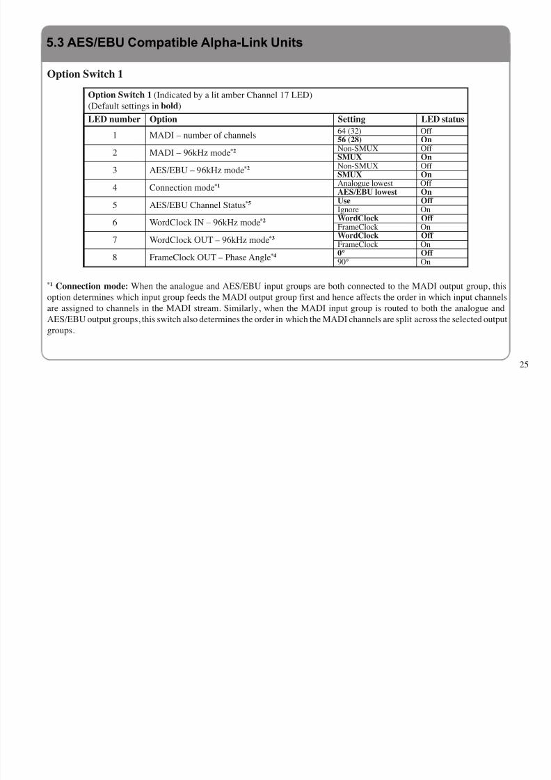
Option Switch 1
*1 Connection mode: When the analogue and AES/EBU input groups are both connected to the MADI output group, this
option determines which input group feeds the MADI output group first and hence affects the order in which input channelsare assigned to channels in the MADI stream. Similarly, when the MADI input group is routed to both the analogue and
AES/EBU output groups, this switch also determines the order in which the MADI channels are split across the selected output
groups.
Option Switch 1 (Indicated by a lit amber Channel 17 LED)
(Default settings in bold)
LED number Option Setting LED status
1 MADI – number of channels64 (32) Off 56 (28) On
2 MADI – 96kHz mode*2 Non-SMUX Off SMUX On
3 AES/EBU – 96kHz mode*2 Non-SMUX Off SMUX On
4 Connection mode*1 Analogue lowest Off AES/EBU lowest On
5 AES/EBU Channel Status*5 Use Off Ignore On
6 WordClock IN – 96kHz mode*2 WordClock Off FrameClock On
7 WordClock OUT – 96kHz mode*3 WordClock Off FrameClock On
8 FrameClock OUT – Phase Angle*4 0° Off 90° On
25
5.3 AES/EBU Compatible Alpha-Link Units

8/8/2019 XLogic Alpha Link
http://slidepdf.com/reader/full/xlogic-alpha-link 30/40
8/8/2019 XLogic Alpha Link
http://slidepdf.com/reader/full/xlogic-alpha-link 31/40
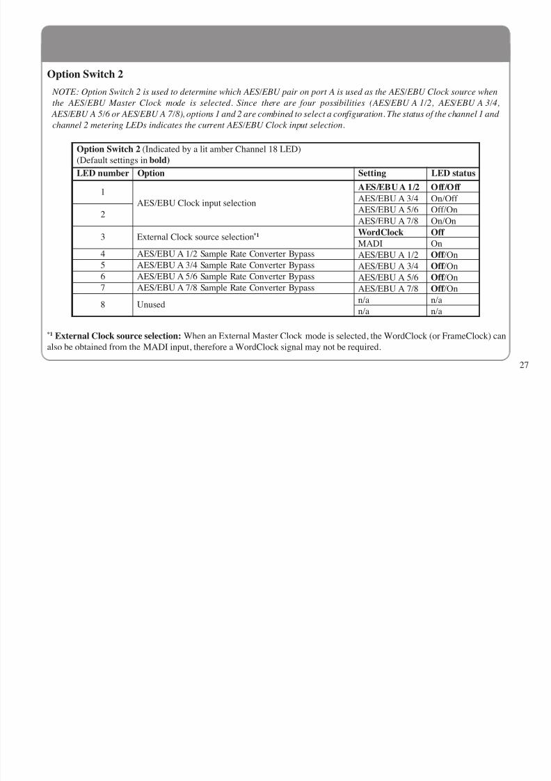
Option Switch 2
NOTE: Option Switch 2 is used to determine which AES/EBU pair on port A is used as the AES/EBU Clock source when
the AES/EBU Master Clock mode is selected. Since there are four possibilities (AES/EBU A 1/2, AES/EBU A 3/4, AES/EBU A 5/6 or AES/EBU A 7/8), options 1 and 2 are combined to select a configuration. The status of the channel 1 and
channel 2 metering LEDs indicates the current AES/EBU Clock input selection.
*1 External Clock source selection: When an External Master Clock mode is selected, the WordClock (or FrameClock) can
also be obtained from the MADI input, therefore a WordClock signal may not be required.
Option Switch 2 (Indicated by a lit amber Channel 18 LED)
(Default settings in bold)
LED number Option Setting LED status
1
AES/EBU Clock input selection
AES/EBU A 1/2 Off/Off
AES/EBU A 3/4 On/Off
2AES/EBU A 5/6 Off/On
AES/EBU A 7/8 On/On
3 External Clock source selection*1 WordClock Off
MADI On4 AES/EBU A 1/2 Sample Rate Converter Bypass AES/EBU A 1/2 Off /On5 AES/EBU A 3/4 Sample Rate Converter Bypass AES/EBU A 3/4 Off /On6 AES/EBU A 5/6 Sample Rate Converter Bypass AES/EBU A 5/6 Off /On7 AES/EBU A 7/8 Sample Rate Converter Bypass AES/EBU A 7/8 Off /On
8 Unusedn/a n/a
n/a n/a
27

8/8/2019 XLogic Alpha Link
http://slidepdf.com/reader/full/xlogic-alpha-link 32/40
28

8/8/2019 XLogic Alpha Link
http://slidepdf.com/reader/full/xlogic-alpha-link 33/40
29
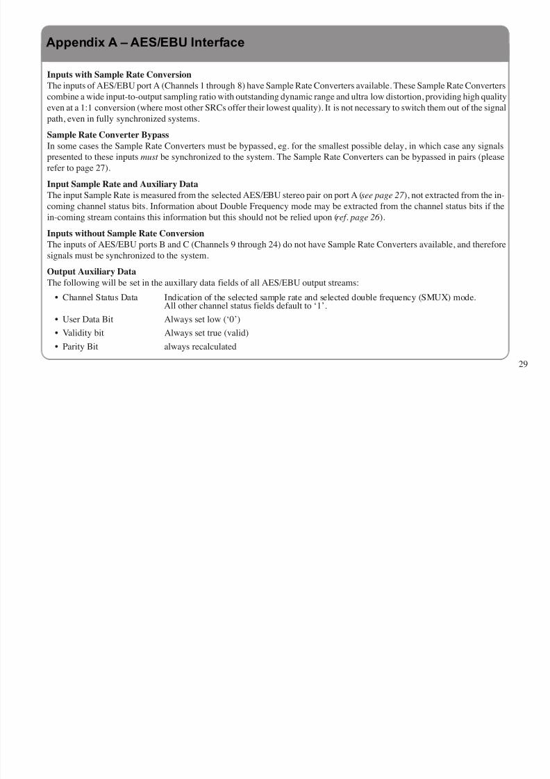
Inputs with Sample Rate Conversion
The inputs of AES/EBU port A (Channels 1 through 8) have Sample Rate Converters available. These Sample Rate Converters
combine a wide input-to-output sampling ratio with outstanding dynamic range and ultra low distortion, providing high quality
even at a 1:1 conversion (where most other SRCs offer their lowest quality). It is not necessary to switch them out of the signal
path, even in fully synchronized systems.
Sample Rate Converter Bypass
In some cases the Sample Rate Converters must be bypassed, eg. for the smallest possible delay, in which case any signals
presented to these inputs must be synchronized to the system. The Sample Rate Converters can be bypassed in pairs (please
refer to page 27).
Input Sample Rate and Auxiliary Data
The input Sample Rate is measured from the selected AES/EBU stereo pair on port A (see page 27 ), not extracted from the in-coming channel status bits. Information about Double Frequency mode may be extracted from the channel status bits if the
in-coming stream contains this information but this should not be relied upon (ref. page 26 ).
Inputs without Sample Rate Conversion
The inputs of AES/EBU ports B and C (Channels 9 through 24) do not have Sample Rate Converters available, and therefore
signals must be synchronized to the system.
Output Auxiliary Data
The following will be set in the auxillary data fields of all AES/EBU output streams:
• Channel Status Data Indication of the selected sample rate and selected double frequency (SMUX) mode.All other channel status fields default to ‘1’.
• User Data Bit Always set low (‘0’)
• Validity bit Always set true (valid)
• Parity Bit always recalculated
Appendix A – AES/EBU Interface
8/8/2019 XLogic Alpha Link
http://slidepdf.com/reader/full/xlogic-alpha-link 34/40
30
What is an interface-frame?
An interface-frame is a structure which contains digital audio data of all channels of one sample taken. A signal which indicates
the boundaries of such interface-frames is called the interface-FrameClock.
NOTE: this “frame” has nothing to do with the familiar video-frame (eg. 24fps). To minimize confusion it is best linked with
its corresponding interface type (eg. AES-frame…).
What is SMUXn?
If a given interface is required to operate at a higher sample rate to that which was originally specified (eg. 48kHz→ 96kHz),
it will not be possible to maintain the same number of channels with the same audio-resolution (eg. 24-bit), without increasing
the interface bandwidth – which may not be possible. A solution to this may be sample-multiplexing or ‘SMUX’, whereby the
original channel count is sacrificed to provide space for a more samples.
• SMUX2: Double Speed (eg. 96kHz):Two (96kHz) samples of a certain channel are now distributed over two former (48kHz) channels (or two WordClock-
ticks). The number of channels is therefore divided by two.
• SMUX4: Quadruple Speed (eg. 192kHz):
Four (192kHz) samples of a certain channel are now distributed over four former (48kHz) channels (or four WordClock-
ticks). The number of channels is therefore divided by four .
Appendix B – Interface FrameClock vs WordClock
8/8/2019 XLogic Alpha Link
http://slidepdf.com/reader/full/xlogic-alpha-link 35/40
31
What is WordClock?
WordClock is a timing reference which indicates the rate at which audio has been sampled (ADC), or generated (DAC). This
signal may be provided in two different forms:
A. Embedded WordClock:
Most interface standards carry some kind of embedded WordClock which clearly indicates the frame-boundaries of that
interface. Some popular interfaces which contain an embedded WordClock are:
• AES: Embedded Wordclock by means of data-encoding violations. This data-encoding is done at an integer multiple of
the sample rate (128 x LR), thus yielding an almost jitter-free WordClock. When operating in SMUX mode this signal
becomes the AES-FrameClock.
• ADAT: Embedded Wordclock by means of data-encoding violations. This data-encoding is done at an integer multiple
of the sample rate (256 x LR), thus yielding an almost jitter-free WordClock. When operating in SMUX mode this signalbecomes the ADAT-FrameClock.
• MADI: Embedded Wordclock by means of a dedicated bit inside the structure. Because MADI uses symbols inside a
fixed length (80ns) frame, a jittery WordClock is obtained. When operating in SMUX mode this signal becomes the
MADI-FrameClock.
B. Dedicated WordClock:
A separate, dedicated WordClock connection is also usually found on the rear panel of professional digital audio equipment.
The typical connector used for this is a 75ohm BNC socket, typically running at +5V pk-pk (‘TTL’ level). Note that when
operating in an SMUX-mode, the WordClock may indicate the base sample rate (eg. 48kHz) rather than the actual sample rate.This signal is often used because it has the least jitter, however this signal is rarely phase-locked to the audio stream(s) with
which it is associated and so can not be guaranteed to indicate frame-boundaries (see “What is SMUXn?” opposite) – problems
can be expected…

8/8/2019 XLogic Alpha Link
http://slidepdf.com/reader/full/xlogic-alpha-link 36/40
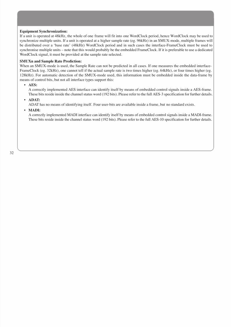
Equipment Synchronization:
If a unit is operated at 48kHz, the whole of one frame will fit into one WordClock period, hence WordClock may be used to
synchronize multiple units. If a unit is operated at a higher sample rate (eg. 96kHz) in an SMUX-mode, multiple frames will
be distributed over a ‘base rate’ (48kHz) WordClock period and in such cases the interface-FrameClock must be used to
synchronise multiple units – note that this would probably be the embedded FrameClock. If it is preferable to use a dedicated
WordClock signal, it must be provided at the sample rate selected.
SMUXn and Sample Rate Prediction:
When an SMUX-mode is used, the Sample Rate can not be predicted in all cases. If one measures the embedded interface-
FrameClock (eg. 32kHz), one cannot tell if the actual sample rate is two times higher (eg. 64kHz), or four times higher (eg.
128kHz). For automatic detection of the SMUX-mode used, this information must be embedded inside the data-frame by
means of control bits, but not all interface types support this:
• AES:A correctly implemented AES interface can identify itself by means of embedded control signals inside a AES-frame.
These bits reside inside the channel status word (192 bits). Please refer to the full AES-3 specification for further details.
• ADAT:
ADAT has no means of identifying itself. Four user-bits are available inside a frame, but no standard exists.
• MADI:
A correctly implemented MADI interface can identify itself by means of embedded control signals inside a MADI-frame.
These bits reside inside the channel status word (192 bits). Please refer to the full AES-10 specification for further details.
32

8/8/2019 XLogic Alpha Link
http://slidepdf.com/reader/full/xlogic-alpha-link 37/40
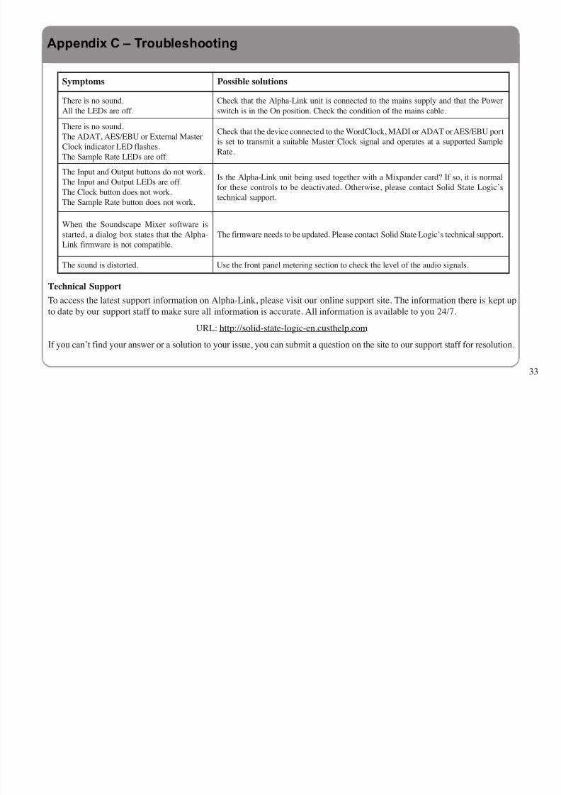
Technical Support
To access the latest support information on Alpha-Link, please visit our online support site. The information there is kept upto date by our support staff to make sure all information is accurate. All information is available to you 24/7.
URL: http://solid-state-logic-en.custhelp.com
If you can’t find your answer or a solution to your issue, you can submit a question on the site to our support staff for resolution.
Symptoms Possible solutions
There is no sound.
All the LEDs are off.
Check that the Alpha-Link unit is connected to the mains supply and that the Power
switch is in the On position. Check the condition of the mains cable.
There is no sound.
The ADAT, AES/EBU or External Master
Clock indicator LED flashes.
The Sample Rate LEDs are off.
Check that the device connected to the WordClock, MADI or ADAT or AES/EBU port
is set to transmit a suitable Master Clock signal and operates at a supported Sample
Rate.
The Input and Output buttons do not work.
The Input and Output LEDs are off.
The Clock button does not work.
The Sample Rate button does not work.
Is the Alpha-Link unit being used together with a Mixpander card? If so, it is normal
for these controls to be deactivated. Otherwise, please contact Solid State Logic’s
technical support.
When the Soundscape Mixer software is
started, a dialog box states that the Alpha-
Link firmware is not compatible.
The firmware needs to be updated. Please contact Solid State Logic’s technical support.
The sound is distorted. Use the front panel metering section to check the level of the audio signals.
Appendix C – Troubleshooting
33

8/8/2019 XLogic Alpha Link
http://slidepdf.com/reader/full/xlogic-alpha-link 38/40
Physical *
Depth 310mm / 12.25" casing only
Height 89mm / 3.5" (1 RU)
Width 438mm / 17.25" casing only482mm / 19" inc’ rack ears
Weight 6kg / 13.25 pounds
Power < 30 Watts
Boxed size 500mm x 600mm x 220mm
20" x 24" x 9"
Boxed weight 8kg / 18 pounds
* All values are approximate
EnvironmentalTemperature Operating: +5 to 30 deg. C
Non-operating: –20 to 50 deg. C
Max. gradient: 15 deg. C/hour
Relative Operating: 20 to 80 %
Humidity Non-operating: 5 to 90 %
Max. wet bulb: 29 deg. C
(non-condensing)
Vibration Operating: < 0.2 G (3 – 100Hz)
Non-operating,
power off: < 0.4 G (3 – 100Hz)
Shock Operating: < 2 G (10ms max.)
Non-operating: < 10 G (10ms max.)
Altitude Operating: 0 to 3000m
(above sea level) Non-operating: 0 to 12000m
Connections
Power IEC320 3-pin connector, 100 – 240 Vac, 50 – 60 Hz
Analogue I/O 6 of 25-pin ‘D’ sockets
provide 24 input and 24 output channels (8 in or out per socket)
• Headphones 1 of ¼" stereo jack (located on front panel)
Digital I/O
• ADAT Tascam TOSLINK™ compatible, JIS F05 connector, 3 pairs
provide 24 input and 24 output channels (8 in/out per pair)
• AES/EBU 3 of 25-pin ‘D’ socket, Zin/out = 110Ω, balanced and isolated
providing 24 input / 24 output channels (8 in/out per socket)
• Expansion Bus 68-pin Hirose DXM series socket
provides 64 channels
• MADI Twin SC type chassis sockets, glass multimode fibre: 50/125µ,
provides 64 channels @ 48kHz
Control
• WordClock 75Ω BNC, Zin = 75Ω, 3V3/5V TTL compatible
• MIDI Ports 2 of 5-pin 180° DIN (1 in, 1 out)
Performance
Quantisation 24bit, fixed point
Sample Rates 44.1kHz, 48kHz, 88.2kHz and 96kHz
Sample Rate Converters Conversion Range 4kHz – 2 12kHz( AES port A input only) Dynamic Range (A-wtd): 128dB
THD+N (1kHz @–60dB): –125dB
Group Delay (@48kHz): 36 samples
Analogue I/O Level +22dBu 0 dB FS
34
Appendix D – Specifications

8/8/2019 XLogic Alpha Link
http://slidepdf.com/reader/full/xlogic-alpha-link 39/40
This equipment has been tested and found to comply
with the limits for a Class B digital device, pursuant
to part 15 of the FCC Rules. These limits are
designed to provide reasonable protection against
harmful interference in a residential installation. Thisequipment generates, uses and can radiate radio frequency energy and, if not installed and
used in accordance with the instructions, may cause harmful interference to radio
communications. However, there is no guarantee that interference will not occur in a
particular installation. If this equipment does cause harmful interference to radio or
television reception, which can be determined by turning the equipment off and on, the
user is encouraged to try to correct the interference by one or more of the following
measures:
• Reorient or relocate the receiving antenna.
• Increase the separation between the equipment and receiver.
• Connect the equipment into an outlet on a circuit different from that to which
the receiver is connected.
• Consult the dealer or an experienced radio/TV technician for help.
Instructions for Disposal of WEEE by Users in the European Union
The symbol shown here is on the product or on its packaging, which
indicates that this product must not be disposed of with other waste. Instead,
it is the user’s responsibility to dispose of their waste equipment by handing
it over to a designated collection point for recycling of waste electrical and
electronic equipment. The separate collection and recycling of your waste
equipment at the time of disposal will help to conserve natural resources and ensure that
it is recycled in a manner that protects human health and the environment. For more
information about where you can drop off your waste equipment for recycling, please
contact your local city office, your household waste disposal service or where you
purchased the product.
Standards Conformance
This apparatus fully conforms with the current protection
requirements of the European community council directives on
EMC and LVD.
WarrantyPursuant to the Solid State Logic Terms and Conditions under European consumer law
the purchaser has full statutory warranty rights for two years from the date of delivery
of the product. The warranty is valid only in those Member States of the European Union
(EU) who have adopted the applicable EU law into their national legislation. Theapplicable national legislation governing the sale of consumer goods is not affected by
this warranty. Warranty claims will only be accepted if the purchased product has been
used for its intended purpose. Any purchased product used for an unintended purpose will
not be eligible for warranty protection. For all warranty inquiries or claims please address
the claim to us if the purchase was directly from us or otherwise to the dealer from which
you purchased the product within a period of two months from the date on which you
detected its lack of conformity with the terms of the warranty. Please include your
original proof of purchase when initiating the claim.
Out of Warranty RepairsIn the event of a fault arising after the warranty period has expired the unit should be
returned to Solid State Logic either directly or via your local dealer. You will be chargedfor the time spent on the repair (at Solid State Logic's current repair rate) plus the cost
of parts and shipping. Note that no units can be accepted for repair without prior
arrangement (see below).
All Returns
• No unit will be accepted for repair by Solid State Logic unless accompanied by a
valid RMA (Return Material Authorisation) number, obtainable from Solid State
Logic prior to shipping.
• All units should be shipped to Solid State Logic in suitable rigid packaging – Solid
State Logic cannot be held responsible for any damage caused by shipping units in
other packaging. In such cases Solid State Logic will return the unit in a suitable
box, which you will be charged for.
• Do not include the power cable, manual or any other items – Solid State Logic can
not guarantee to return them to you.
Tested To Complywith FCC Standards
FOR HOME OR OFFICE USE
35

8/8/2019 XLogic Alpha Link
http://slidepdf.com/reader/full/xlogic-alpha-link 40/40
Visit SSL at URL: http://www.solid-state-logic.com
82S6ALS10C
© Solid State LogicAll Rights reserved under International and Pan-American Copyright Conventions
VHD, VHD logo, Xlogic, XLogic Delta and Xlogic Alpha are trademarks of Solid State Logic
All other product names and trademarks are the property of their respective owners and are hereby acknowledged
No part of this publication may be reproduced in any form or by any means, whether mechanical or
electronic, without the written permission of Solid State Logic, Oxford, OX5 1RU, England
As research and development is a continual process, Solid State Logic reserves the right to change
the features and specifications described herein without notice or obligation.
Solid State Logic cannot be held responsible for any loss or damage arising directly or indirectly
from any error or omission in this manual.
E&OE