XL POWERSPORT FULL RANGE AMPLIFIER - … · The PC board features a conformal coating that resists...
28
XL-3515M XL-5675M XL POWERSPORT FULL RANGE AMPLIFIER Owners Manual Please read through this manual to familiarize yourself with your new amplifier. Should your PowerBass Xtreme mobile amplifier ever require service, you will need to have the original dated receipt.
Transcript of XL POWERSPORT FULL RANGE AMPLIFIER - … · The PC board features a conformal coating that resists...

XL-3515MXL-5675M
XL POWERSPORT FULL RANGE AMPLIFIER
Owners ManualPlease read through this manual to familiarize yourself with your new amplifi er. Should your PowerBass
Xtreme mobile amplifi er ever require service, you will need to have the original dated receipt.

Thank you and Congratulations
Thank you for your decision to purchase a PowerBass USA Xtreme mobile amplifier! Our new mini amplifiers
are the result of extensive engineering, testing, and bullet proof construction. Their versatility enables compat-
ibility with optional signal and audio processors. These high quality MOSFET amplifiers may be configured to
allow maximum flexibility in designing different types of speaker systems.
FULL RANGE CLASS D MINI AMPLIFIERS
The PowerBass XL Series are high quality MOSFET amplifiers that are capable of running a system full range,
or they may be selected only to power subwoofers. It is important that you closely follow the wiring instructions
contained in this Owners Manual so that you get the most from your PowerBass Xtreme mobile amplifier.
∆ Caution ∆
High powered audio systems in a vehicle are capable of generating higher than “Live Concert” levels of sound pressure. Continued exposure
to excessively high volume sound levels could cause hearing loss or damage. Also, operation of a motor vehicle while listening to audio
equipment at high volume levels may impair your ability to hear external sounds such as horns, warning signals, or emergency vehicles—thus
creating a potential traffic hazard. In the interest of safety, PowerBass USA highly recommends listening at lower volume levels when driving.
AMPLIFIERS

3
TECHNICAL FEATURES
• FRD (Full Range Class-D) Multi-Channel Technology • International Rectifier Chip Set • Conformal Coated PC Board to Resist Moisture, Dust and Extreme Heat• AUX Input Accepts MP3, iPod® or Portable Source Device• Wrap-around Aluminum Heatsink Shell• Ultra Low Current Draw • High Damping Control Circuit • High Efficiency SMD Circuit Technology • 4-Layer Copper Plated PCB • Digital Sound Optimization Circuitry • Quiet Switching • Bass EQ Circuitry Centered at 45Hz (+/- 18dB)• High Current Voltage Ripple Rejection Circuitry • Virtual Silence Turn On/Off Mute Circuit• Advanced Protection Circuitry• Low Level RCA and High Level Speaker Inputs
*iPod® is a registered trademark of Apple
FRD-FULL RANGE CLASS D TECHNOLOGY
This amplifier represents the very latest in Class D technology. The XL Series uses the new IR® (International Rectifier) platform which has been under development for the past several years. IR®, a leader in PWM circuit design, has worked in conjunction with PowerBass engineers to produce more stable power output, minimal RF interference and improved sound quality.
The benefits of this cooperative effort are many and include improved temperature, frequency, voltage regulation and drive capability to name a few.
The PC board features a conformal coating that resists moisture, dust and extreme heat. Combine that plus their small size and these amplifiers are perfect for many Powersport applications including UTV, golf cart and motorcycle and Watersport vessels.
The result to the user is a all around improved product that will provide years of listening enjoyment.
IR® is a registered trademark of International Rectifier Corporation.

INSTALLATION EXPERIENCE
Installation of PowerBass mobile amplifiers requires detailed knowledge of electronics wiring and proper speaker impedance. We strongly recommend installation by an authorized PowerBass dealer. This Owners Manual only provides general installation and operation instructions. If you have any reservations about your installation skills, please contact your local PowerBass dealer for assistance.
IMPORTANT : This amplifier is designed for operation in vehicles with 12-volt Negative ground electrical systems only.
PREPARING FOR INSTALLATION
NOTE: The tools listed below may be required for basic installation• An electric drill with bits• Philips head and standard screwdrivers• Wire strippers• Crimping tool• VOM (electronic volt ohm meter)• Heat shrink tubing and heat gun• Soldering iron• Electronic (Rosen not Acid Core) Solder
INSTALLATION PRECAUTIONS
NOTE: Proceed only if you are a qualified installer, otherwise; see your Authorized PowerBass Dealer to professionally install this amplifier. Always wear protective eyewear when using tools.
• Turn off all stereo and other electrical devices before you begin.• Disconnect the negative (-) lead from your vehicles battery.• Locate all fuel lines, brake lines, oil lines, and electrical cables when planning the install.• Make sure there is at least 2-inches (5 cm) around the air vents on the amplifier.• When connecting ground points, make sure all paint is carefully scrapped away from the auto body
and contact is made with bare metal.• Use a utility knife to trim away fabric from hole locations before drilling or cutting.• When running power cables through sheet metal, be sure to use grommets to properly insulate the
metal edges from the wire insulation.• If possible, use tubing through grommets.
WARNING: Check your vehicle’s owner’s manual before disconnecting the battery. Disconnecting the battery on some vehicles may require an anti-theft code when reconnecting the battery and require the on-board computer to be reset at the dealership. Check with your local dealer if you are uncertain.
5
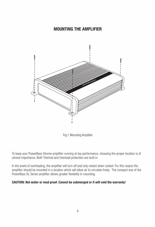
To keep your PowerBass Xtreme amplifier running at top performance, choosing the proper location is of utmost importance. Both Thermal and Overload protection are built in.
In the event of overheating, the amplifier will turn off and only restart when cooled. For this reason the amplifier should be mounted in a location which will allow air to circulate freely. The compact size of the PowerBass XL Series amplifier allows greater flexibility in mounting.
CAUTION: Not water or mud proof. Cannot be submerged or it will void the warranty!
Fig.1 Mounting Amplifier
MOUNTING THE AMPLIFIER

MOUNTING LOCATION
The XL Series amplifiers have a conformal coating applied to the PC board. This coating makes them resistant to water and dust—however they are not waterproof. Therefore, care should still be taken to protect the am-plifier from water and find a mounting location that is not likely to get wet. Take care not to mount in a vehicle/vessel where it can cause interference with the factory installed electronic devices. The unique wrap around outer shell (heatsink) allows the XL Series amplifiers to be mounted in spaces with minimal air flow. It is important that whatever location is selected the amplifier must be mounted securely in a manner keeps the unit intact even during rough jolts that can occur to the vehicle/vessel.
You may use the amplifier as a template and mark the four screw locations with a felt tip pen. Set the amplifier aside before drilling. Use caution to make sure there are no objects behind the installation surface that may become damaged during drilling.
If mounting under a seat, make sure there is at least 1-inch (2.5 cm) of space above the amplifier’s heatsink to permit proper cooling.
The best places to mount your amplifier are: The floor of the trunk, under a seat, on the back of the rear seat or a storage compartment where air can circulate. For alternate installation locations, please consult your authorized PowerBass Dealer.
NOTE: Do not use a drill with driver bit to mount the amplifier. Excessive force could cause the plastic mounting feet to crack.
6
*** WARNING ***• Do not install in a place where it could injure the driver or passengers if the vehicle
stops suddenly.• Try to avoid mounting the amplifier on a subwoofer enclosure, as extended exposure
to vibration may cause malfunction of the amplifier.• Don’t mount the amplifier so that the wire connections are unprotected or are sub-
ject to pinching or damage from nearby objects.• The DC power wire must be fused at the battery positive (+) terminal connection.
Before making or breaking power connections at the amplifier power terminals, disconnect the DC power wire at the battery end.
• The battery of the car audio system must be disconnected until the entire wiring and installation is completed.
7
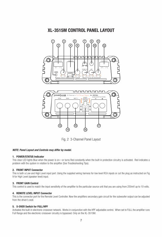
XL-3515M CONTROL PANEL LAYOUT
NOTE: Panel Layout and Controls may differ by model.
1. POWER/STATUS IndicatorThis clear LED lights Blue when the power is on—or turns Red constantly when the built-in protection circuitry is activated. Red indicates a problem with the system in relation to the amplifier (See Troubleshooting Tips). 2. FRONT INPUT ConnectorThis is both a Low and High Level input port. Using the supplied wiring harness for low level RCA inputs or cut the plug as instructed on Fig 9 for High Level (speaker level) input. 3. FRONT GAIN ControlThis control is used to match the input sensitivity of the amplifier to the particular source unit that you are using from 250mV up to 10 volts. 4. REMOTE LEVEL INPUT Connector This is the connector port for the Remote Level Controller. Now the amplifiers secondary gain circuit for the subwoofer output can be adjusted from the driver’s seat.
5. X-OVER Switch for FULL/HPFActivates the built-in electronic crossover network. Works in conjunction with the HPF adjustable control. When set to FULL the amplifier runs Full Range and the electronic crossover circuitry is bypassed. Only on the XL-3515M.
Fig. 2 3-Channel Panel Layout

6. HPF (High Pass Filter)This control is continuously adjustable from 40Hz to 400Hz at 12dB per octave when the x-over switch is set to HPF. (XL-3515M only).
7. MODE Switch Matches the input from the Source Unit to that of the amplifier, either 2 or 3 Channel. This eliminates the use of “Y” adapters and provides a cleaner input signal. When the 2-Channel mode is selected, both front and sub outputs will operate with only one pair of low level RCA / high level inputs. (Must use front inputs) When the 3-CH MODE is selected, both the front and subwoofer inputs will be used. This will allow fading between the front and subwoofer outputs.
8. BASS EQ ControlThis equalization circuit is used to enhance the low frequency response of the vehicle’s interior. With up to 18dB of boost centered at 45Hz, the BASS EQ can be adjusted to meet your own personal taste.
9. AUX Input JackThis 1/8-inch (3.5mm) mini jack can be used to accept an MP3, iPOD or smartphone as the source unit from that devices headphone (3.5mm) output. NOTE: MODE switch needs to be in the 2CH setting when using AUX Input. 10. LPF (Low Pass Filter)This control is continuously adjustable from 50Hz to 150Hz at 12dB per octave.
11. SUBWOOFER GAIN ControlThis control is used to match the input sensitivity of the amplifier to the particular source unit that you are using up to 250mV to 10 volts.
12. SUBWOOFER INPUT ConnectorThis is both a Low and High Level Input port. Using the supplied wiring harness for low level RCA inputs or cut the plug as instructed on Fig.9 for High Level (speaker level) input. 13. GND (Ground Input Connection)A good quality ground is required for your PowerBass Xtreme amplifier to operate at peak performance. A short length of cable the same gauge as your power cable should be used to attach the ground terminal directly to the chassis of the vehicle. Make sure that all of the paint is sanded or scraped away to ensure a quality ground connection. NOTE: If installing in a boat, UTV or motorcycle make sure your ground wire is connected to the negative ( - ) terminal of the battery.
14. REM (Remote Input Connection)This terminal must be connected to a switched +12V source. Typically, remote turn-on leads are provided at the source unit that will turn on and off the amplifier in correspondence with the source. If this lead is not at the source unit, then a switched +12V supply must be used, like the ACC, +12V. 15. BATT+ (Power Input Connection)This terminal is the main power input for the amplifier and must be connected directly to the positive (+) terminal of the car battery. The solderless terminal block is designed to accommodate up to 4-gauge power wire. FUSE-IMPORTANTDue to the limited space on the XL amplifier chassis they do NOT come with internal fusing! Instead we have included an in-line fuse holder that can be connected directly to the BATT+ input on the amplifier. Please note the proper ampere fuse for each model are listed below. Never replace a fuse with a higher rating then what is listed. XL-3515M uses 60A, XL-5675M uses 80A 16. FRONT SPEAKER OUTPUTThis 4-pin Molex style connector is where the speaker output harness plugs in. Be sure to observe the correct speaker polarity and follow the speaker wiring diagrams starting on page 21.
17. SUBWOOFER OUTPUTSet screw subwoofer output terminal. Be sure to observe the correct speaker polarity and follow the speaker wiring diagrams starting on page 21.
8
9
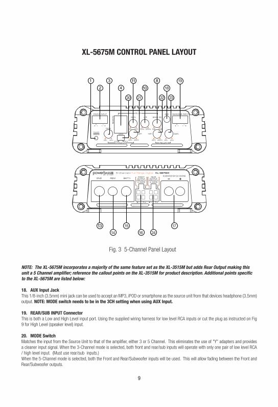
XL-5675M CONTROL PANEL LAYOUT
NOTE: The XL-5675M incorporates a majority of the same feature set as the XL-3515M but adds Rear Output making this unit a 5 Channel amplifier; reference the callout points on the XL-3515M for product description. Additional points specific to the XL-5675M are listed below:
18. AUX Input JackThis 1/8-inch (3.5mm) mini jack can be used to accept an MP3, iPOD or smartphone as the source unit from that devices headphone (3.5mm) output. NOTE: MODE switch needs to be in the 3CH setting when using AUX Input.
19. REAR/SUB INPUT ConnectorThis is both a Low and High Level input port. Using the supplied wiring harness for low level RCA inputs or cut the plug as instructed on Fig 9 for High Level (speaker level) input.
20. MODE Switch Matches the input from the Source Unit to that of the amplifier, either 3 or 5 Channel. This eliminates the use of "Y" adapters and provides a cleaner input signal. When the 3-Channel mode is selected, both front and rear/sub inputs will operate with only one pair of low level RCA / high level input. (Must use rear/sub inputs.) When the 5-Channel mode is selected, both the Front and Rear/Subwoofer inputs will be used. This will allow fading between the Front and Rear/Subwoofer outputs.
Fig. 3 5-Channel Panel Layout

10
21. FRONT HPF (High Pass Filter)This control is continuously adjustable from 40Hz to 400Hz at 12dB per octave.
22. REAR HPF (High Pass Filter)This control is continuously adjustable from 40Hz to 400Hz at 12dB per octave.
23. REAR GAIN ControlThis control is used to match the input sensitivity of the amplifier to the particular source unit that you are using from to 250mV up to 10 volts. 24. REAR SPEAKER OutputThis 4-pin Molex style connector is where the speaker output harness plugs in. Be sure to observe the correct speaker polarity and follow the speaker wiring diagrams starting on page 21.

11
Your PowerBass Xtreme amplifier requires unrestricted current to deliver peak performance, so do not “starve” your amplifier by using small power cable. Using under sized power cable can result in unnecessary over-heating of the amplifier, distortion at high volume levels and might even cause the thermal protection circuitry to shut-off the amplifier. Remember, bigger wire is better! For best results we recommend a PowerBass ampli-fier install kit, available at your local PowerBass dealer.
• Use rubber grommets when running cables through any metal or sharp plastic, to prevent accidental shorting or shearing. Make sure the cables do not interfere with normal operation of the vehicle.
• The audio signal cables (RCA interconnects) should be kept far away from any potential sources of electrical interference such as electronic vehicle management systems (relays, engine computers etc.), wiring harnesses, fuel pumps etc.
These amplifiers are designed to work within a 10 to 16 volt DC range. Before any wires are connected, the vehicles electrical system should be checked for correct voltage supply with the help of a voltmeter.
First, check the voltage at the battery with the ignition in the OFF position. The voltmeter should read no less than 12V. If your vehicles electrical system is not up to these specifications, we recommend having it checked by an auto electrician before any further installation. Once the vehicle is checked, make certain the correct cable gauge is used. The XL amplifier terminals are capable of accepting up to 8 gauge power and ground cable. We recommend using as large a gauge cable as possible, use the Power Cable Selection Chart to cal-culate the correct power wire size for your application.
POWER WIRING AND SIGNAL CONNECTIONS
Fig.4 Power Input Connection
*** WARNING ***Disconnect the negative (-) battery terminal before you start any wiring work! The battery of your car audio system must be disconnected until the entire wiring installation is completed.

12
Fig.5 Proper Chassis Ground Connection For Cars And Trucks
POWER WIRING
BATT+ (Power)This amplifier should be wired directly to the vehicle battery using the appropriate size cable. Start at the vehicle battery and run the power cable through to the amplifier. Avoid running the power cable over engine components and near heater cores. The use of an inline fuse or circuit breaker is a must; this will pre-vent the risk of a potential fire caused by a short in your power cable. Connect the fuse holder or circuit breaker as close to the battery positive (+) terminal as possible (within 18” from the battery). This fuse or circuit breaker should be no greater then the sum of the fuses found on the chassis of your amplifier (also see specifications chart). You may now connect the cable to the battery, but remember to leave the fuse out or circuit breaker “off” until all other cable connections are made.
GND (Ground)When grounding your amplifier, locate a metal area close to the amplifier that is good source of ground (preferable the floor pan). Use a short length of cable the same gauge as your power cable. Once again, investigate the area you wish to use for electrical wires, vacuum lines, and brake or fuel lines. Use either a wire brush or sandpaper to eliminate unwanted paint for better contact of the ground. NOTE: If installing in a boat, UTV or motorcycle make sure your ground wire is connected to the negative ( - ) terminal of the battery. See Fig. 5
Secure the ground cable to the body using a bolt, star washer and nut. Spread silicon over the screw and bare metal to prevent rust and possible water leaks.
For Power Sport applications such as UTVs, motorcycles and boats it is highly recommended to wire both the Ground (GND) and Positive (BATT+) cables from the amplifier directly to the battery. NOTE: The Ground must be capable of carrying the same amount of current as the positive wire.
Now it’s time to connect the power and ground cables to the amplifier. Cut both cables to length. Strip off 1/2 inch (12mm) of the insulation so that the bare wire fits all the way in the terminal block on the side panel of the amplifier, seating it firmly so no bare wire is exposed. Use a screw driver to losen the BATT+ and the GND connection on the amplifier. Insert the ground first, and then the +12V and please make sure that you place them into the correctly marked terminals. Hand thighten the set screws and make sure the connection is secure to prevent possible arcing due to loose screws.
13
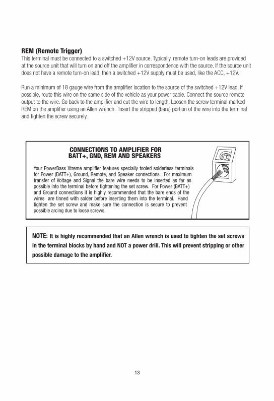
REM (Remote Trigger)This terminal must be connected to a switched +12V source. Typically, remote turn-on leads are provided at the source unit that will turn on and off the amplifier in correspondence with the source. If the source unit does not have a remote turn-on lead, then a switched +12V supply must be used, like the ACC, +12V.
Run a minimum of 18 gauge wire from the amplifier location to the source of the switched +12V lead. If possible, route this wire on the same side of the vehicle as your power cable. Connect the source remote output to the wire. Go back to the amplifier and cut the wire to length. Loosen the screw terminal marked REM on the amplifier using an Allen wrench. Insert the stripped (bare) portion of the wire into the terminal and tighten the screw securely.
NOTE: It is highly recommended that an Allen wrench is used to tighten the set screws
in the terminal blocks by hand and NOT a power drill. This will prevent stripping or other
possible damage to the amplifier.

14
FUSE REQUIREMENTS
Due to the small size of the PowerBass XL series amplifiers, no fuses are incorporated into the panels that normally protect the unit from excessive current. Instead we have included an in-line fuse holder and fuse for this purpose.
Remember this fuse does nothing to protect the vehicle/vessel from a dangerous short circuit.
It is absolutely vital that the main power lead to the amplifier(s) in the system be fused within 18-inches (45cm) of the connection to the battery.
Fig.6 Proper Ground Connection For UTVs, Motorcycles or Boats
Proper Ground Connection For UTVs, Motorcycles or Boats
15
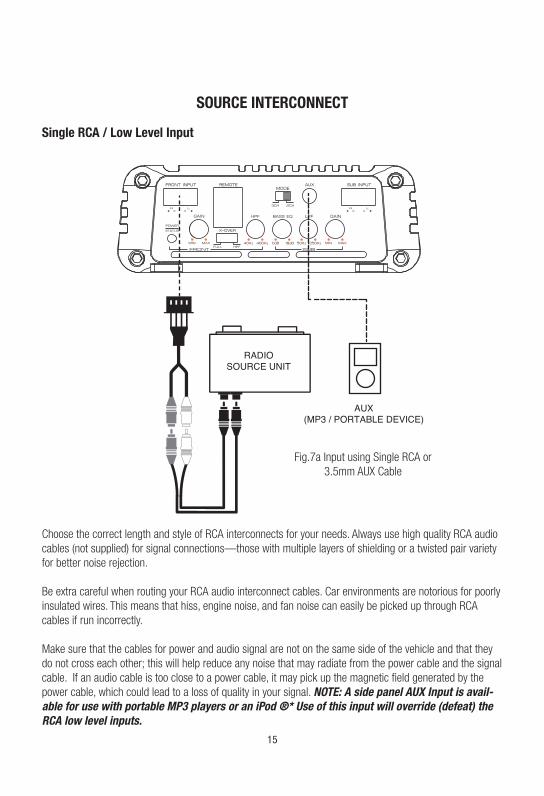
SOURCE INTERCONNECT
Fig.7a Input using Single RCA or 3.5mm AUX Cable
Choose the correct length and style of RCA interconnects for your needs. Always use high quality RCA audio cables (not supplied) for signal connections—those with multiple layers of shielding or a twisted pair variety for better noise rejection.
Be extra careful when routing your RCA audio interconnect cables. Car environments are notorious for poorly insulated wires. This means that hiss, engine noise, and fan noise can easily be picked up through RCA cables if run incorrectly.
Make sure that the cables for power and audio signal are not on the same side of the vehicle and that they do not cross each other; this will help reduce any noise that may radiate from the power cable and the signal cable. If an audio cable is too close to a power cable, it may pick up the magnetic field generated by the power cable, which could lead to a loss of quality in your signal. NOTE: A side panel AUX Input is avail-able for use with portable MP3 players or an iPod ®* Use of this input will override (defeat) the RCA low level inputs.
Single RCA / Low Level Input

16
SOURCE INTERCONNECT
Fig.8 Input using two pairs of RCA cables
Dual RCA / Low Level Input (Front and Subwoofer)
17
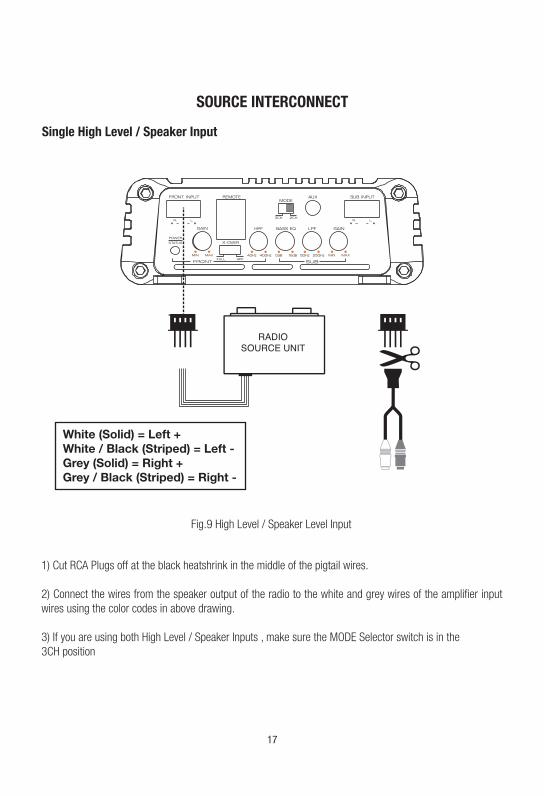
White (Solid) = Left +White / Black (Striped) = Left -Grey (Solid) = Right +Grey / Black (Striped) = Right -
Fig.9 High Level / Speaker Level Input
1) Cut RCA Plugs off at the black heatshrink in the middle of the pigtail wires.
2) Connect the wires from the speaker output of the radio to the white and grey wires of the amplifier input wires using the color codes in above drawing.
3) If you are using both High Level / Speaker Inputs , make sure the MODE Selector switch is in the 3CH position
SOURCE INTERCONNECT
Single High Level / Speaker Input

18
BASS EQ ControlThis special feature is designed to provide you more powerful sound quality, and it allows you to increase the bass output up to +18dB at 45Hz (Sub Channel only). Keep in mind more is not always better. Setting the control to the max (18dB) may stress the amplifier and woofer and could result in damage.
NOTE: More is not always better. By turning the BASS EQ all the way up to 18dB you can overwork the amplifier and send the unit into thermal protection.
This control allows you to match the input level of the amplifier to the output level of your head unit. Matching the input can be accomplished in three simple steps:1. Set the volume of GAIN on the amplifier to Min (completely counter clock wise).2. Turn on the head unit and adjust volume to 2/3 maximum, and set the BASS and TREBLE to zero.3. Adjust the GAIN control clockwise until the sound just begins to distort, then back off slightly to cut
distortion and operate at optimum gain.Remember, the GAIN control is not a volume control. Ignoring the three steps above may leave you with damaged speaker and/or a damaged amplifier.
SET UP ADJUSTMENTS
INPUT Gain Adjustment
Control Panel (3) and (11)GAIN Control
Control Panel (8)Bass EQ Control
Control Panel (10)Low Pass Control (LPF)
GAIN
MIN MAX
50Hz 250Hz
LPF (Low Pass Filter) AdjustmentAdjust the LPF frequency for your subwoofer(s) operation. Using the LPF control, adjust the Low Pass Fre-quency to limit the amount of midrange going to your subwoofers.
19
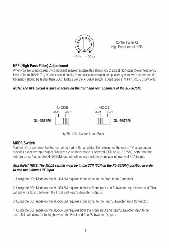
Fig.10 2-5 Channel Input Mode
MODE Switch Matches the input from the Source Unit to that of the amplifier. This eliminates the use of “Y” adapters and provides a cleaner input signal. When the 2-Channel mode is selected (3CH on XL-5675M), both front and sub (front/rear/sub on the XL-5675M) outputs will operate with only one pair of low level RCA inputs.
AUX INPUT NOTE: The MODE switch must be in the 2CH (3CH on the XL-5675M) position in order to use the 3.5mm AUX input
1) Using the 2CH Mode on the XL-3515M requires input signal to the Front Input Connector.
2) Using the 3CH Mode on the XL-3515M requires both the Front Input and Subwoofer Input to be used. This will allow for fading between the Front and Rear/Subwoofer Outputs.
3) Using the 3CH mode on the XL-5675M requires input signal to the Rear/Subwoofer Input Connector.
4) Using the 5CH mode on the XL-5675M requires both the Front Input and Rear/Subwoofer Input to be used. This will allow for fading between the Front and Rear/Subwoofer Outputs.
HPF (High Pass Filter) AdjustmentWhen you are using coaxial or component speaker system, this allows you to adjust high-pass X-over frequency from 40Hz to 400Hz. To get better sound quality from coaxial or component speaker system, we recommend the frequency should be higher than 80Hz. Make sure the X-OVER switch is positioned at “HPF”. (XL-3515M only)
NOTE: The HPF circuit is always active on the front and rear channels of the XL-5675M.
40Hz 400Hz
3CH
XL-3515M XL-5675M
3CH 5CH
Control Panel (6)High Pass Control (HPF)
20
SPEAKER WIRING AND CONFIGURATIONS
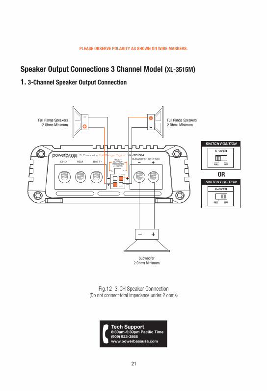
Speaker LoadKeep in mind your PowerBass Xtreme amplifier is a high power amplifier and not a high current amplifier. In other words this amplifier requires a minimum impedance of 2 ohms STEREO and 4 ohms bridged (2-ohms MONO on SUB channel) to operate trouble free. Lower impedance will send the amplifier into protection and possibly damage the electronics inside and void the waranty.
NOTE: Know your total impedance load before you make any connections.
Speaker WiringChoose the correct speaker wire for your application. Most applications will require a minimum of 16 gauge wire. At the amplifier end, splice the speaker wires to the properly marked output leads from the Molex style connector. Route these using the same precautions as you did when you ran the power cable. Check to make sure you’ve maintained proper polarity and balance.
CAUTION:Maintaining proper impedance is critical when wiring the Full Range Digital model amplifiers. Improper
wiring can cause severe damage to BOTH the speakers and the amplifier. Detailed wiring diagrams
are supplied with all PowerBass woofers. IF YOU ARE NOT EXPERIENCED OR UNCOMFORTABLE
READING THE WIRING DIAGRAMS CONSULT YOUR AUTHORIZED POWERBASS DEALER BEFORE YOU
ATTEMPT TO WIRE THE SYSTEM.
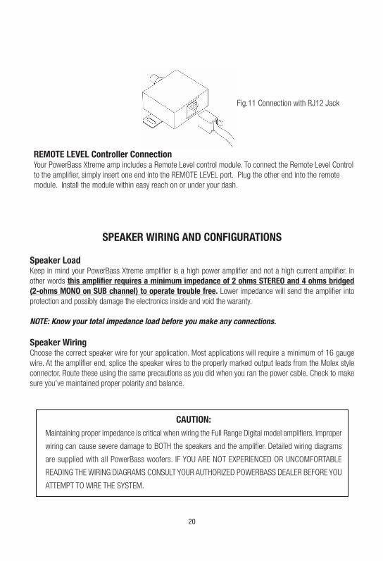
REMOTE LEVEL Controller ConnectionYour PowerBass Xtreme amp includes a Remote Level control module. To connect the Remote Level Control to the amplifier, simply insert one end into the REMOTE LEVEL port. Plug the other end into the remote module. Install the module within easy reach on or under your dash.
Fig.11 Connection with RJ12 Jack
21
Speaker Output Connections 3 Channel Model (XL-3515M)
1. 3-Channel Speaker Output Connection
Fig.12 3-CH Speaker Connection(Do not connect total impedance under 2 ohms)
PLEASE OBSERVE POLARITY AS SHOWN ON WIRE MARKERS.

22
Speaker Output Connections 5 Channel Model (XL-5675M)
3. 5-Channel Speaker Output Connection
Fig.13 5-CH Speaker Connection / 2 ohms minimum
PLEASE OBSERVE POLARITY AS SHOWN ON WIRE MARKERS.

4. 3-Channel Stereo/Mono Speaker Output Connection
Fig.14 3-CH Speaker Connection
23
Speaker Output Connections 3 Channel Model (XL-5675M)
PLEASE OBSERVE POLARITY AS SHOWN ON WIRE MARKERS.
NOTE: For the XL-3515M follow the same bridge connection from the Front Output in the above diagram if you need to run a mono output for the front channel.

24
RECOMMENDED WIRE SIZESPower Cable Selection Chart
Fuse Total 4Ft 4-7Ft 7-10Ft 10-13Ft 13-16 Ft 16-19 Ft 19-22 Ft
In Amperes Length of Wire/Gauge
150A - 200A 2 GA 2 GA 2 GA *1/0* *1/0* *1/0* *1/0*
125A - 150A 4 GA 4 GA 4 GA 4 GA 2 GA 2 GA 2 GA
105A - 125A 8 GA 8 GA 8 GA 4 GA 4 GA 4 GA 2 GA
85A - 105A 8 GA 8 GA 8 GA 4 GA 4 GA 4 GA 4 GA
65A - 85A 10 GA 8 GA 8 GA 8 GA 4 GA 4 GA 4 GA
50A - 65A 10 GA 10 GA 8 GA 8 GA 8 GA 8 GA 8 GA
35A - 50A 10 GA 10 GA 10 GA 8 GA 8 GA 8 GA 8 GA
25A - 35A 10GA 10GA 10GA 10GA 8GA 8GA 8GA
PowerBass makes several types of amplifier wiring kits to assist with the installation of your PowerBass amplifier. Consult your local PowerBass dealer for details. For more information about recommended power wire check out our website at www.powerbassusa.com.
PERSONAL NOTES:
Name: ______________________________________________________________
Date Purchased: ______________________________________________________
Dealer: _____________________________________________________________
Installed By: _________________________________________________________
Model: _____________________________________________________________
Serial Number: ______________________________________________________
Miscellaneous: ______________________________________________________
This manual is the exclusive property of PowerBass USA, Inc. Any reproduction of this manual, or use other than its intentions is strictly prohibited without the express consent of PowerBass USA, Inc. © Copyright 2016 PowerBass USA, Inc.
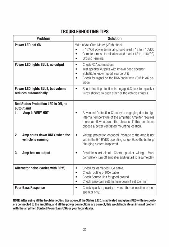
TROUBLESHOOTING TIPSProblem Solution
Power LED not ON With a Volt Ohm Meter (VOM) check:• +12 Volt power terminal (should read +12 to +16VDC• Remote turn-on terminal (should read +12 to +16VDC)• Ground Terminal
Power LED lights BLUE, no output • Check RCA connections• Test speaker outputs with known good speaker• Substitute known good Source Unit• Check for signal on the RCA cable with VOM in AC po-
sition
Power LED lights BLUE, but volume reduces automatically.
• Short circuit protection is engaged.Check for speaker wires shorted to each other or the vehicle chassis.
Red Status Protection LED is ON, no output and1. Amp is VERY HOT
2. Amp shuts down ONLY when the
vehicle is running
3. Amp has no output
• Advanced Protection Circuitry is engaging due to high internal temperature of the amplifier. Amplifer requires more air flow around the chassis. If this continues choose a better ventilated mounting location.
• Voltage protection engaged. Voltage to the amp is not within the 9-16 VDC operating range. Have the battery/charging system inspected.
• Possible short circuit. Check speaker wiring. Must completely turn off amplifier and restart to resume play.
Alternator noise (varies with RPM) • Check for damaged RCA cable.• Check routing of RCA cable• Check Source Unit for good ground• Check amp gain setting, turn down if set too high
Poor Bass Response • Check speaker polarity, reverse the connection of one speaker only.
NOTE: After using all the troubleshooting tips above, if the Status L.E.D. is activated and glows RED with no speak-ers connected to the amplifier, and all the power connections are correct, this would indicate an internal problem with the amplifier. Contact PowerBass USA or your local dealer.
25

SPECIFICATIONS FOR XL MULTICHANNEL AMPLIFIERS
Three Channel Model XL-3515M
4 Ohms Power (Watts) 80 x 2 + 250 x 1
2 Ohms Power (Watts) 160 x 2 + 350 x 1
Peak Music Power (Watts) 1340
THD @ RMS Power < 0.2%
Frequency Response 10Hz - 40kHz
S/N Ratio (EIA Rated) > 85dB
Input Sensitivity 250mV - 10.0 volts
Crossover Slope 12dB
High-Pass Crossover Freq. (Hz) 40Hz - 400Hz
Low-Pass Crossover Freq. (Hz) 50Hz - 250Hz
Recommended Fuse* 60A* AGU
Dimensions (LxWxH) 9.6" x 4.5" x 1.6" (243 x 114 x 40mm )
Five Channel Model XL-5675M
4 Ohms Power (Watts) 80 x 4 + 250 x 1
2 Ohms Power (Watts) 160 x 4 + 350 x 1
4 Ohms Mono Power (Watts) 320 x 2 + 350 x 1 (Sub 2-ohm)
Peak Music Power (Watts) 1980
THD @ RMS Power < 0.2%
Frequency Response 10Hz - 40kHz
S/N Ratio (EIA Rated) >85dB
Input Sensitivity 250mV - 10.0 volts
Crossover Slope 12dB
High-Pass Crossover Freq. (Hz) 40Hz - 400Hz (Front/Rear)
Low-Pass Crossover Freq. (Hz) 50Hz - 250Hz (Sub)
Variable Subwoofer EQ 0 - 18dB
Subwoofer EQ Freq. 45Hz
Recommended Fuse* 80A* AGU
Dimensions (LxWxH) 11.2" x 4.5" x 1.6" (284 x 114 x 40mm )
*REQUIRES EXTERNAL FUSE !Important Notes:-Due to continuing improvements these specifications are subject to change without any notice.-Do not attempt to fix or repair this unit. Unauthorized repairs will void the manufacturer’s warranty.
POWERBASS ELECTRONICS LIMITED WARRANTY POLICY
PowerBass USA, Inc. offers limited warranty on PowerBass products under normal use on the following terms:
PowerBass Xtreme Amplifiers are to be free of defects in material and workmanship for a period of one (1) year.
This warranty applies only to PowerBass products sold to consumers by Authorized PowerBass Dealers in the United States of America. Products purchased by consumers from a PowerBass dealer in another country are covered only by that country’s Distributor and not by PowerBass USA.
This warranty covers only the original purchaser of PowerBass product. In order to receive service, the purchaser must provide PowerBass with the receipt stating the consumer name, dealer, product and date of purchase.
Products found to be defective during the warranty period will be repaired or replaced (with a product deemed to be equivalent) at PowerBass’s discretion and will not be liable for incidental or consequential damages. PowerBass will not warranty this product under the following situations:
• Amplifiers received with apparent rust or corrosion
• Any evidence of liquid damage or exposure to excessive heat
• Attempted repairs or alterations of any nature
• Product that has not been installed according to this owners manual
Any implied warranties including warranties of fitness for use and merchantability are limited in duration to the period of the express warranty set forth above. Some states do not allow limitations on the length of an implied warranty, so this limitation may not apply. No person is authorized to assume for PowerBass any other liability in connection with the sale of this product.
Please call (909) 923-3868 for PowerBass Customer Service. You must obtain an RA# (Return Authorization Num-ber) to return any product to PowerBass. The RA number must be prominently marked on the outside of the shipping carton or the delivery will be refused. Please pack your return carefully; we are not responsible for items damaged in shipping. Return the defective product along with a copy of the original dated retail sales receipt, plus $12.00 for handling and diagnostic evaluation to:
PowerBass USA, Inc., Attn: Returns (RA#__________)2133 S. Green Privado, Ontario, CA 91761
Residents of HI, AK and US territories will be charged for return shipping. All inquires regarding service and warranty should be sent to the above address.
Removed or altered serial numbers will void this warranty

PowerBass Xtreme – A division of PowerBass USA, Inc.
2133 S. Green Privado – Ontario, CA 91761
Tel. (909) 923-3868 – Fax (909) 923-8048
www.powerbassusa.com
©2016