XI.M41 BURIED AND UNDERGROUND PIPING AND TANKS … · The terms buried and und erground are fully...
24
11 Aug 2010 1 XI.M41 BURIED AND UNDERGROUND PIPING AND TANKS Program Description This is a comprehensive program designed to manage the aging of the external surfaces of buried and underground piping and tanks and to augment other programs which manage the aging of internal surfaces of buried and underground piping and tanks. It addresses piping and tanks composed of any material, including metallic, polymeric, cementitious and concrete materials. This program manages aging through preventive, mitigative and inspection activities. It manages all applicable aging effects such as loss of material, cracking, and changes in material properties. Depending on the material, preventive and mitigative techniques include: the material itself, external coatings for external corrosion control, the application of cathodic protection and the quality of backfill utilized. Also, depending on the material, inspection activities include electrochemical verification of the effectiveness of cathodic protection, non-destructive evaluation of pipe or tank wall thicknesses, hydrotesting of the pipe, and visual inspections of the pipe or tank from the exterior as permitted by opportunistic or directed excavations. With, in some cases, the assistance of this program, management of aging of the internal surfaces of buried and underground piping and tanks is accomplished through the use of other aging management programs (e.g. Open Cycle Cooling Water (AMP XI.M20), Treated Water (AMP XI.M21A), Internal Inspection of Miscellaneous Piping and Ducts (AMP XI.M38), Fuel Oil Chemistry (AMP XI.M30), Fire Water System (AMP XI.M27) or Water Chemistry (AMP XI.M2). Additionally, this program does not address selective leaching. The selective leaching program (AMP XI.M33) is applied in addition to this program for applicable materials and environments. The terms “buried” and “underground” are fully defined in Chapter IX of the GALL Report. Briefly, buried piping and tanks are in direct contact with soil or concrete (e.g., a wall penetration). Underground piping and tanks are below grade, but are contained within a tunnel or vault such that they are in contact with air and are located where access for inspection is restricted. Evaluation and Technical Basis
Transcript of XI.M41 BURIED AND UNDERGROUND PIPING AND TANKS … · The terms buried and und erground are fully...

11 Aug 2010
1
XI.M41 BURIED AND UNDERGROUND PIPING AND TANKS Program Description This is a comprehensive program designed to manage the aging of the external surfaces of buried and underground piping and tanks and to augment other programs which manage the aging of internal surfaces of buried and underground piping and tanks. It addresses piping and tanks composed of any material, including metallic, polymeric, cementitious and concrete materials. This program manages aging through preventive, mitigative and inspection activities. It manages all applicable aging effects such as loss of material, cracking, and changes in material properties. Depending on the material, preventive and mitigative techniques include: the material itself, external coatings for external corrosion control, the application of cathodic protection and the quality of backfill utilized. Also, depending on the material, inspection activities include electrochemical verification of the effectiveness of cathodic protection, non-destructive evaluation of pipe or tank wall thicknesses, hydrotesting of the pipe, and visual inspections of the pipe or tank from the exterior as permitted by opportunistic or directed excavations. With, in some cases, the assistance of this program, management of aging of the internal surfaces of buried and underground piping and tanks is accomplished through the use of other aging management programs (e.g. Open Cycle Cooling Water (AMP XI.M20), Treated Water (AMP XI.M21A), Internal Inspection of Miscellaneous Piping and Ducts (AMP XI.M38), Fuel Oil Chemistry (AMP XI.M30), Fire Water System (AMP XI.M27) or Water Chemistry (AMP XI.M2). Additionally, this program does not address selective leaching. The selective leaching program (AMP XI.M33) is applied in addition to this program for applicable materials and environments. The terms “buried” and “underground” are fully defined in Chapter IX of the GALL Report. Briefly, buried piping and tanks are in direct contact with soil or concrete (e.g., a wall penetration). Underground piping and tanks are below grade, but are contained within a tunnel or vault such that they are in contact with air and are located where access for inspection is restricted. Evaluation and Technical Basis

Summary of Comments on Microsoft Word - XI M41 11 Aug 2010-1Page: 1
Author: Paul Subject: Highlight Date: 8/24/2010 2:56:22 PM This is a proposed revision to NUREG 1801 (GALL). This is a very positive step in that: 1. It covers pipes and tanks other than steel and includes all pipe and tank materials 2. It covers tanks and pipes that may contain radioactive liquids in excess of EPA drinking water limits 3.It covers buried portions of partially piping systems and partially buried tanks such as CST, Waste tanks, RWST's Spent Fuel Pools, fuel transfer canals, refueling cavities and containments and drywells. What is the regulatory authority of a NUREG? Will this AMP be applicable for those plants that have received an extended license? Brian Holian confirmed during this meeting this AMP will this be applicable to plants presently under review. Can the NRC take any enforcement action if a licensee fails to meet the guidance of this NUREG? Other sites such as Indian Point contain (3) 700# natural gas lines ranging in size from 26 to 30 inches in diameter. Are the natural gas pipes buried on the Indian Point site pipes covered by this proposed program? Are there sites other than IP that have pipes containing hazardous materials not under the direct control of the licensee? Author: Paul Subject: Highlight Date: 8/24/2010 12:34:52 PM Service Water Piping Does this program apply to service water systems where the majority of the piping is buried. At lease two plants, in response to GL 89-13 have excluded the buried portions of the SW systems and the NRC has accepted these positions. XI.M20 only requires inspection of "lined or coated" SW pipes. (See Seabrook LRA) Will this AMP supercede M20? Review of responses and many LRAs, there are no requirements for internal and/or external inspections of the SW piping systems and branch lines. Which AMP assures the integrity of the SW systems in all nuclear plants? What are the specific requirements for the inspections of buried SW systems that have experienced numerous internal corrosion failures and in some cases, required the replacement of the majority of service water piping.
Author: Paul Subject: Highlight Date: 8/24/2010 12:36:30 PM Why only external surfaces only? Many pipes have failed due to internal mechanisms, From my years at Millstone, Indian Point and Maine Yankee, Connecticut Yankee and recent tritium leaks at Vermont Yankee I recall numerous internal failures of piping systems within the scope of 10 CFR 54.4. or containing HAZMAT as defined within. The environment and chemistry on the external surfaces remains fairly stable however the internal surfaces are exposed to a wide range of temperature and chemistry. (i.e. service water), potentially more destructive than the external environments. MIC is one form of severe internal corrosion that has internally degraded many nuclear piping systems yet this is not being addressed in this program. There have been numerous reported failures of internal coatings of nuclear plant systems and internal erosion and cracking. Why are these failure mechanisms not addressed in this proposed program? This program must be modified to address internal corrosion which is the most common failure mechanisms
Comments from page 1 continued on next page

11 Aug 2010
1
XI.M41 BURIED AND UNDERGROUND PIPING AND TANKS Program Description This is a comprehensive program designed to manage the aging of the external surfaces of buried and underground piping and tanks and to augment other programs which manage the aging of internal surfaces of buried and underground piping and tanks. It addresses piping and tanks composed of any material, including metallic, polymeric, cementitious and concrete materials. This program manages aging through preventive, mitigative and inspection activities. It manages all applicable aging effects such as loss of material, cracking, and changes in material properties. Depending on the material, preventive and mitigative techniques include: the material itself, external coatings for external corrosion control, the application of cathodic protection and the quality of backfill utilized. Also, depending on the material, inspection activities include electrochemical verification of the effectiveness of cathodic protection, non-destructive evaluation of pipe or tank wall thicknesses, hydrotesting of the pipe, and visual inspections of the pipe or tank from the exterior as permitted by opportunistic or directed excavations. With, in some cases, the assistance of this program, management of aging of the internal surfaces of buried and underground piping and tanks is accomplished through the use of other aging management programs (e.g. Open Cycle Cooling Water (AMP XI.M20), Treated Water (AMP XI.M21A), Internal Inspection of Miscellaneous Piping and Ducts (AMP XI.M38), Fuel Oil Chemistry (AMP XI.M30), Fire Water System (AMP XI.M27) or Water Chemistry (AMP XI.M2). Additionally, this program does not address selective leaching. The selective leaching program (AMP XI.M33) is applied in addition to this program for applicable materials and environments. The terms “buried” and “underground” are fully defined in Chapter IX of the GALL Report. Briefly, buried piping and tanks are in direct contact with soil or concrete (e.g., a wall penetration). Underground piping and tanks are below grade, but are contained within a tunnel or vault such that they are in contact with air and are located where access for inspection is restricted. Evaluation and Technical Basis
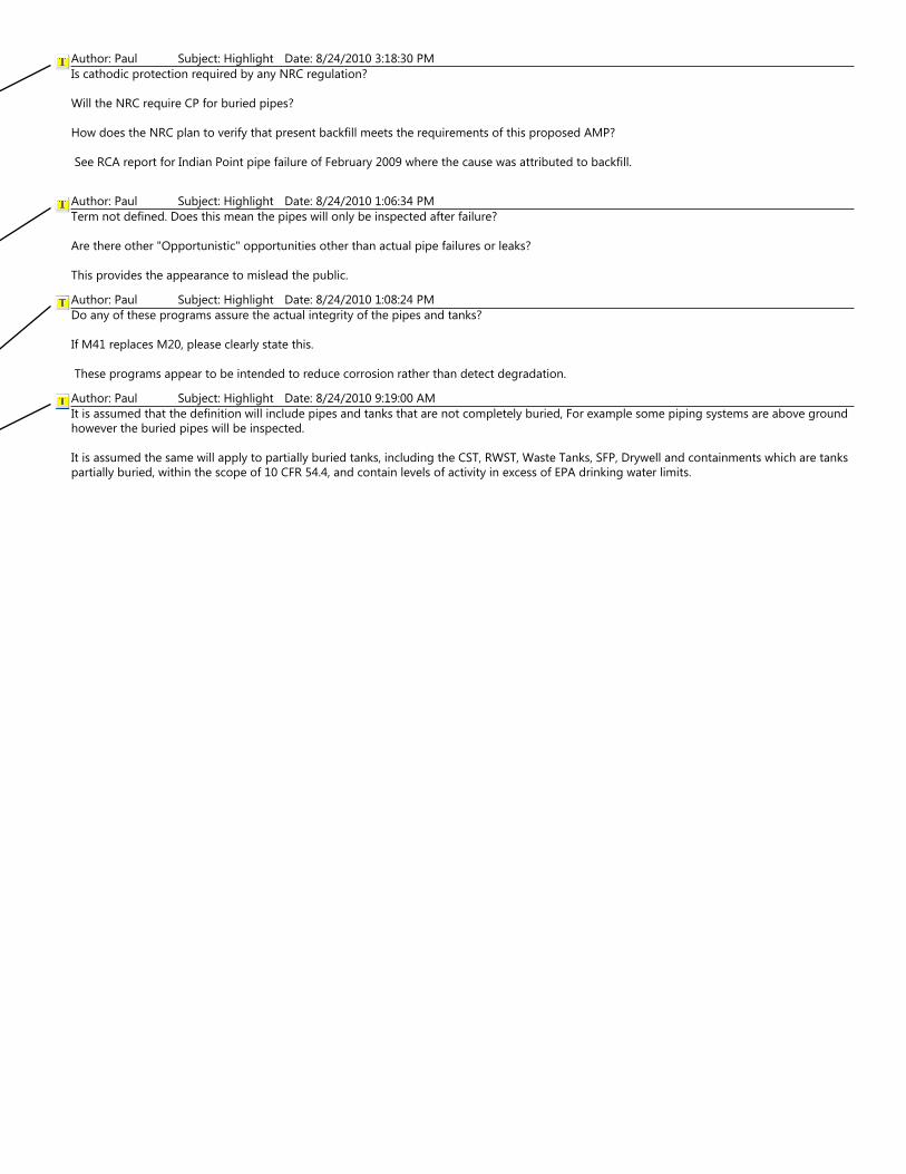
Author: Paul Subject: Highlight Date: 8/24/2010 3:18:30 PM Is cathodic protection required by any NRC regulation? Will the NRC require CP for buried pipes? How does the NRC plan to verify that present backfill meets the requirements of this proposed AMP? See RCA report for Indian Point pipe failure of February 2009 where the cause was attributed to backfill.
Author: Paul Subject: Highlight Date: 8/24/2010 1:06:34 PM Term not defined. Does this mean the pipes will only be inspected after failure? Are there other "Opportunistic" opportunities other than actual pipe failures or leaks? This provides the appearance to mislead the public. Author: Paul Subject: Highlight Date: 8/24/2010 1:08:24 PM Do any of these programs assure the actual integrity of the pipes and tanks? If M41 replaces M20, please clearly state this. These programs appear to be intended to reduce corrosion rather than detect degradation. Author: Paul Subject: Highlight Date: 8/24/2010 9:19:00 AM It is assumed that the definition will include pipes and tanks that are not completely buried, For example some piping systems are above ground however the buried pipes will be inspected. It is assumed the same will apply to partially buried tanks, including the CST, RWST, Waste Tanks, SFP, Drywell and containments which are tanks partially buried, within the scope of 10 CFR 54.4, and contain levels of activity in excess of EPA drinking water limits.

11 Aug 2010
2
1. Scope of Program: This program is used to manage the effects of aging for buried and underground piping and tanks constructed of any material including metallic, polymeric, cementitious and concrete materials. The program addresses aging effects such as loss of material, cracking, and changes in material properties. Typical systems in which buried and underground piping and tanks may be found include service water piping and components, condensate storage transfer lines, fuel oil and lubricating oil lines, fire protection piping and piping components (fire hydrants), and storage tanks. Corrosion of piping system bolting within the scope of this program is managed using this program. Other aging effects associated with piping system bolting are managed through the use of the Bolting Integrity Program (AMP XI.M18).
2. Preventive Actions: Preventive actions utilized by this program vary with the
material of the tank or pipe and the environment (air, soil, or concrete) to which it is exposed. These actions are outlined below:
a. Preventive Actions, Buried Piping and Tanks
i. Preventive actions for buried piping and tanks are conducted in accordance with Table 2a and its accompanying footnotes
ii. Fire mains are installed in accordance with National Fire Protection
Association (NFPA) Standard 24. Preventive actions for fire mains beyond those in NFPA 24 need not be provided if the system undergoes a periodic flow test in accordance with NFPA 25 as described in program element 4 of this AMP.
Table 2a, Preventive Actions for Buried Piping and Tanks
Material1 Coating2 Cathodic
Protection4
Backfill Quality
Titanium
Super Austenitic Stainless8
Stainless Steel X3 X5, 7
Steel X X X5
Copper X X X5

Page: 2
Author: Paul Subject: Highlight Date: 8/23/2010 6:20:19 PM Many tanks such as the CST and the RWST are in contact with sand, concrete or soil but are only partially buried. It is not clear if these tanks are within the scope of this proposed program. Many internal failures of tanks have been reported over the past 30 years. How would these failure be detected by this proposed program. (VY CST and the CY RWST have experienced internal failures) The spent fuel pool and the contaminants are "tanks" meeting the requirements of the above definition in that it is encased in concrete and/or soil and at many reactors, is below the surface of the ground. The same is true for the Spent Fuel Pool. Author: Paul Subject: Highlight Date: 8/24/2010 12:39:13 PM How does the NRC expect the licensee to inspect "bolting" of valves and flanges of buried pipes without any periodic external visual inspections? A logical conclusion is that it is likely that external bolting of buried pipes will never be inspected during the entire 60 years of plant operation. How is piping integrity assured in the event of a common mode event such as a earthquake? Author: Paul Subject: Highlight Date: 8/23/2010 11:01:35 AM My concern is the structural integrity of these pipes. Please explain how any flow test verifies the integrity of these pipes?

11 Aug 2010
3
Aluminum X X X5
Cementitious or Concrete
X3 X5, 7
Polymer X6
1. Materials classifications are meant to be broadly interpreted; e.g., all
alloys of titanium which are commonly used for buried piping are to be included in the titanium category. Material categories are generally aligned with P numbers as found in the ASME Code, Section IX. Steel is defined in chapter IX of this report. Polymer includes polymeric materials as well as composite materials such as fiberglass.
2. When provided, coatings are in accordance with Table 1 of NACE
SP0169-2007 or Section 3.4 of NACE RP0285-2002.
3. Coatings are provided based on environmental conditions (e.g., stainless steel in chloride containing environments). If coatings are not provided, a justification is provided in the LRA.
4. Cathodic protection is in accordance with NACE SP0169-2007 or NACE
RP0285-2002. The system monitoring interval discussed in section 10.3 of NACE SP0169-2007 may not be extended beyond one year. The equipment used to implement cathodic protection need not be 10 CFR 50 Appendix B qualified. Cathodic protection need not be provided if:
a. Soil resistivities > 20,000 ohm cm. If this condition is met, inspections
in Table 4a are conducted in accordance with Table 4a footnote 2 item C.
b. Corrosion rates, based on at least 5 years of data, which indicate that
minimum design wall thickness for the buried pipe or tank will not be reached within the period of extended operation. The corrosion rates may be based on measurements taken from actual uncoated pipe or may be approximated for coated piping, which is assumed to contain flaws in the coating, from bare metal coupons of similar material exposed, on site, to soil of similar conditions (e.g., resistivity, ionic content, moisture content, etc). Multiple corrosion measurements are necessary when a length of pipe passes through varying soil types. If this condition is met, inspections in Table 4a are conducted in accordance with Table 4a footnote 2 item D.

Page: 3
Author: Paul Subject: Highlight Date: 8/24/2010 12:40:58 PM How will the NRC assure that these backfill and cathodic protections measures are implemented or verified? Will the NRC require any type of physical verification? Author: Paul Subject: Highlight Date: 8/23/2010 6:26:26 PM Does this infer that all metallic pipes have or are required to have cathodic protection unless the following conditions are met? Will the NRC require cathodic protection be added to protect these pipes?

11 Aug 2010
4
5. Backfill is consistent with SP0169-2007 section 5.2.3. The staff considers
backfill which is located within 6 inches of the pipe that meets ASTM D 448-08 size number 67 to meet the objectives of SP0169-2007. Backfill quality may be demonstrated by plant records or by examining the backfill while conducting the inspections conducted in program element 4 of this AMP. Backfill not meeting this standard is acceptable if the inspections conducted in program element 4 of this AMP do not reveal evidence of mechanical damage to pipe coatings due to the backfill.
6. Aggregate size for backfill within 6 inches of the pipe must meet ASTM
D 448-08 size number 10.
7. Backfill limits apply only if piping is coated.
8. Super austenitic stainless steel, e.g., Al6XN or 254 SMO. b. Preventive Actions, Underground Piping and Tanks
i. Preventive actions for underground piping and tanks are conducted in accordance with Table 2b and its accompanying footnotes
Table 2b, Preventive Actions for Underground Piping and Tanks
Material1 Coating
Provided2 Titanium
Super Austenitic Stainless4
Stainless Steel X3
Steel X Copper X
Aluminum X3
Cementitious or Concrete
Polymer
1. Materials classifications are meant to be broadly interpreted; e.g., all alloys of titanium which are commonly used for buried piping are to be

Page: 4
Author: Paul Subject: Highlight Date: 8/24/2010 12:42:24 PM Are the presently operating plants in compliance with this standard? If not will they be required to backfit or verified to meet these requirements? See IP-2 RCA for CST line failure of February 2009. Author: Paul Subject: Highlight Date: 8/23/2010 11:10:26 AM Are there any preventative measures for internal corrosion control such as epoxy or concrete. If the pipes are lined are there any requirements to inspect the integrity of the internal lining or coatings? Author: Paul Subject: Highlight Date: 8/23/2010 6:26:59 PM Other materials such as monel, bronze, etc. are commonly used in nuclear plants. Are these materials covered by this program?

11 Aug 2010
5
included in the titanium category. Material categories are generally aligned with P numbers as found in the ASME Code, Section IX. Steel is defined in chapter IX of this report. Polymer includes polymeric materials as well as composite materials such as fiberglass.
2. When provided, coatings are in accordance with Table 1 of NACE
SP0169-2007 or Section 3.4 of NACE RP0285-2002. A broader range of coatings may be used if justification is provided in the LRA.
3. Coatings are provided based on environmental conditions (e.g., stainless
steel in chloride containing environments). If coatings are not provided, a justification is provided in the LRA.
4. Super austenitic stainless steel, e.g., Al6XN or 254 SMO.
3. Parameters Monitored/Inspected: The aging effects addressed by this AMP
are: changes in material properties of polymeric materials, loss of material due to all forms of corrosion and, potentially, cracking due to stress corrosion cracking. Changes in material properties are monitored by manual examinations. Loss of material is monitored by visual appearance of the exterior of the piping or tank; and wall thickness of the piping or tank. Wall thickness is determined by a non-destructive examination technique such as ultrasonic testing (UT). Two additional parameters, the pipe-to-soil potential and the cathodic protection current, are monitored for steel, copper, and aluminum piping and tanks in contact with soil to determine the effectiveness of cathodic protection systems and, thereby, the effectiveness of corrosion mitigation.
4. Detection of Aging Effects: Methods and frequencies used for the detection of
aging effects vary with the material and environment of the buried and underground piping and tanks. These methods and frequencies are outlined below.
a. Opportunistic Inspections
i. All buried and underground piping and tanks, regardless of their material of construction are inspected by visual means whenever they become accessible for any reason. The information in paragraph f of this program element is applied in the event deterioration of piping or tanks is observed.

Page: 5
Author: Paul Subject: Highlight Date: 8/24/2010 12:44:31 PM What if they never become accessible for any reason? Is this OK? Wall thickness and integrity must be periodically verified.

11 Aug 2010
9
E Coatings and backfill are in accordance with NACE SP0169-2007 and Table 2a but cathodic protection is not provided.
F Preventive actions provided do not meet criteria C, D, or E.
3. Inspections are listed as either a discrete number of visual examinations
(excavations) or as a percentage of the linear length of piping under consideration. The following guidance related to the extent of inspections is provided:
a. Each inspection will examine either the entire length of a run of pipe
or a minimum of 10 feet. b. If the length of pipe to be inspected based on the number of
inspections times the minimum inspection length (10 feet) exceeds 10% of the length of the piping under consideration, only 10% need be inspected.
c. If the length of pipe to be inspected based on the total length of pipe
under consideration times percentage to be inspected is less than 10 feet, either 10 feet or the total length of pipe present, whichever is less, will be inspected.
4. Code Class and safety related pipe which also meets the definition of
hazmat pipe will be inspected as hazmat pipe. 5. Hazmat pipe is pipe which, during normal operation, contains material
which, if released, could be detrimental to the environment. This includes chemical substances such as diesel fuel and radioisotopes. To be considered hazmat, the concentration of radioisotopes within the pipe during normal operation must exceed established standards such as EPA drinking water standard. In the absence of such standards, the concentration of the radioisotope must exceed the greater of background or reliable level of detection. For tritium, the EPA drinking water standard (20,000 pCi/L) is used. (This approach for defining hazmat is consistent with that used in classifying fluid services in ASME B31.3 appendix M.)
6. Only 1 inspection is conducted even if both Code Class/safety related and
hazmat pipe are present.

Page: 9
Author: Paul Subject: Highlight Date: 8/23/2010 11:24:17 AM This is very confusing. If a service water system contains 10,000 feet of buried pipes, how many feet of pipe will be excavated and inspected? Will every branch line be inspected? Author: Paul Subject: Highlight Date: 8/24/2010 12:46:40 PM Insert "and tanks"

11 Aug 2010
10
7. Super austenitic stainless steel, e.g., Al6XN or 254 SMO. 8. High Density Polyethylene (HDPE) pipe includes only HDPE pipe
approved for use by the NRC for buried applications. 9. Other polymer piping includes some HDPE pipe, and all other polymeric
materials including composite materials such as fiberglass. c. Directed Inspections – Underground Pipe
i. Directed inspections for underground piping are conducted in accordance with Table 4b and its accompanying footnotes.
ii. Unless otherwise indicated, directed inspections as indicated in Table 4b
will be conducted during each 10 year period beginning 10 years prior to the entry into the period of extended operation.
iii. Inspection locations are selected based on susceptibility to degradation.
Characteristics such as coating type, coating condition, exact external environment, and flow characteristics within the pipe, are considered.
iv. Underground pipes are inspected visually to detect external corrosion and
by a volumetric technique such as UT to detect internal corrosion. v. Opportunistic examinations may be credited toward these direct
examinations if the location selection criteria in item iii, above, are met. vi. At multi-unit sites, individual inspections of shared piping may be
credited for only one unit. vii. Visual inspections for polymeric materials are augmented with
manual examinations to detect hardening, softening or other changes in material properties.
viii. The use of guided wave ultrasonic or other advanced inspection
techniques is encouraged for the purpose of determining those piping locations that should be inspected but may not be substituted for the inspections listed in the table.

Page: 10
Author: Paul Subject: Highlight Date: 8/24/2010 12:55:14 PM As I understand this technology it is an unproven method to assure the structural integrity of buried pipes. The word "encouraged" is meaningless is a regulatory environment and obligates a licensee to nothing.

11 Aug 2010
11
ix. For the purpose of this program element, fire mains will be considered to be code class/safety related piping and inspected as such unless they are subjected to a flow test as described in section 7.3 of NFPA 25 at an frequency of at least one test in each six month period.
x. Inspection as indicated in (A), and (B) below may be performed in lieu of
the inspections contained in Table 4a for either code class/safety significant or hazmat piping or both:
A. At least 25% of the code class/safety related or hazmat piping or both
constructed from the material under consideration is hydrostatically tested in accordance with 49 CFR 195 subpart E on an interval not to exceed 5 years.
B. At least 25% of the code class/safety related or hazmat piping or both
constructed from the material under consideration is internally inspected by a method capable of precisely determining pipe wall thickness. The inspection method must be capable of detecting both general and pitting corrosion and must be qualified by the applicant and approved by the staff. As of the effective date of this document, guided wave ultrasonic examinations do not meet this paragraph. Internal inspections are to be conducted at an interval not to exceed 5 years. Consideration should be given to SP0169-2007 sections 6.1.2 and 6.3.3
Table 4b, Inspections of Underground Pipe
Material1 Inspections2
Code Class Safety Related3
Hazmat4
Titanium Super
Austenitic Stainless6
Stainless Steel
15 15
HDPE7 15 15 Other
Polymer8 15 15

Page: 11
Author: Paul Subject: Highlight Date: 8/24/2010 12:56:44 PM A flow test is not able to detect either internal or external degradation of pipes. A fire mail could experience severe degradation not detected by a flow test and fail as a result of an earthquake when it is most likely needed. Author: Paul Subject: Highlight Date: 8/24/2010 12:57:41 PM Subpart H of 49 CFR 196 for corrosion control and other applicable parts of 49 CFR 195 must be included. 49 CFR 195 only applies to steel pipes. Will this testing apply to all pipes?

11 Aug 2010
13
radioisotope must exceed the greater of background or reliable level of detection. For tritium, the EPA drinking water standard (20,000 pCi/L) is used. (This approach for defining hazmat is consistent with that used in classifying fluid services in ASME B31.3 appendix M)
5. Only 1 inspection is conducted even if both Code Class/safety related and
hazmat pipe are present. 6. Super austenitic stainless steel, e.g., Al6XN or 254 SMO. 7. HDPE pipe includes only HDPE pipe approved for use by the NRC for
buried applications. 8. Other polymer piping includes some HDPE pipe, and all other polymeric
materials including composite materials such as fiberglass. d. Directed Inspections – Buried Tanks
i. Directed inspections for buried tanks are conducted in accordance with Table 4c and its accompanying footnotes.
ii. Directed inspections as indicated in Table 4c will be conducted during
each 10 year period beginning 10 years prior to the entry into the period of extended operation.
iii. Each buried tank is examined if it is Code Class/safety related or contains
hazardous materials as defined in footnote 5 to Table 4a and is constructed from a material for which an examination is indicated in Table 4c.
iv. Examinations may be conducted from the external surface of the tank
using visual techniques or from the internal surface of the tank using volumetric techniques. If the tank is inspected from the external surface a minimum 25% coverage is required. This area must include at least some of both the top and bottom of the tank. If the tank is inspected internally by UT, at least 1 measurement is required per square foot of tank surface. UT measurements are distributed uniformly over the surface of the tank. If the tank is inspected internally by another volumetric technique, at least 90% of the surface of the tank must be inspected.

Page: 13
Author: Paul Subject: Highlight Date: 8/24/2010 12:58:54 PM Need a very clear definition for "buried tanks"

11 Aug 2010
20
b. On September 6, 2005, a service water leak was discovered in a buried service water header. The header had been in service for 38 years. The cause of the leak was either failure of the external coating or damage caused by improper backfill. The service water header was relocated above ground.
c. In October 2007, degradation of essential service water piping was
reported. The riser pipe leak was caused by a loss of pipe wall thickness due to external corrosion induced by the wet environment surrounding the unprotected carbon steel pipe. The corrosion processes that caused this leak affected all eight similar locations on the essential service water riser pipes within vault enclosures and had occurred over many years
d. In February 2009, a leak was discovered on the return line to the condensate
storage tank. The cause of the leak was coating degradation probably due to the installation specification not containing restrictions on the type of backfill allowing rocks in the backfill. The leaking piping was also located close to water table.
e. In April 2009, a leak was discovered in an aluminum pipe where it went
through a concrete wall. The piping was for the condensate transfer system. The failure was caused by vibration of the pipe within its steel support system. This vibration led to coating failure and eventual galvanic corrosion between the aluminum pipe and the steel supports.
f. In June 2009, an active leak was discovered in buried piping associated with
the condensate storage tank. The leak was discovered because elevated levels of tritium were detected. The cause of the through-wall leaks was determined to be the degradation of the protective moisture barrier wrap which allowed moisture to come in contact with the piping resulting in external corrosion.
References 10 CFR Part 50, Appendix B, Quality Assurance Criteria for Nuclear Power
Plants, Office of the Federal Register, National Archives and Records Administration, 2009.
NACE Standard SP0169-2007, Control of External Corrosion on Underground or
Submerged Metallic Piping Systems, 2007.

Page: 20
Author: Paul Subject: Highlight Date: 8/23/2010 12:12:14 PM A comprehensive listing of pipe failures due to internal corrosion and degradation should also be provided. Provide a listing of only external corrosion failures leads to a inference that pipes do not degrade do to internal mechanisms. Author: Paul Subject: Highlight Date: 8/23/2010 12:19:17 PM Is it possible to obtain a copy of these standards from the NRC?

11 Aug 2010
21
NACE Standard RP0285-2002, Standard Recommended Practice Corrosion Control of Underground Storage Tank Systems by Cathodic Protection, revised April 2002.
NFPA Standard 24, Standard for the Installation of Private Fire Service Mains and
Their Appurtenances, 2010 edition. ASTM Standard D 448-08, Standard Classification for Sizes of Aggregate for
Road and Bridge Construction, 2008. NFPA Standard 25, Standard for the Inspection, Testing, and Maintenance of
Water-Based Fire Protection Systems, 2008 edition. 49 CFR 195 subpart E, Transportation of Hazardous Liquids by Pipeline, Pressure Testing. ASME Standard B31.3 – 2002, Process Piping, Appendix M. ASME Boiler and Pressure Vessel Code, Section IX, Welding and Brazing.

Page: 21
Author: Paul Subject: Highlight Date: 8/23/2010 12:19:18 PM Author: Paul Subject: Highlight Date: 8/23/2010 12:19:23 PM Author: Paul Subject: Highlight Date: 8/23/2010 12:19:27 PM Author: Paul Subject: Highlight Date: 8/23/2010 12:19:33 PM Author: Paul Subject: Highlight Date: 8/23/2010 12:19:42 PM Author: Paul Subject: Highlight Date: 8/23/2010 12:19:39 PM