Xilinx XAPP1053 Flash Memory Bootloading Using SPI … · Xilinx EDK software, version 9.2 Xilinx...
14
XAPP1053 (v1.0) February 8, 2008 www.xilinx.com 1 © 2008 Xilinx, Inc. All rights reserved. XILINX, the Xilinx logo, and other designated brands included herein are trademarks of Xilinx, Inc. All other trademarks are the property of their respective owners. Summary The Xilinx Spartan™-3A DSP FPGA features the ability to configure from standard serial flash over a built-in Serial Peripheral Interface (SPI). Being general-purpose flash, the SPI serial flash can also be used for any other non-volatile storage that the user may need. One such non- volatile purpose is the storage of MicroBlaze™ processor application code for bootloading. Included Systems Included with this application note is one reference system: www.xilinx.com/support/documentation/application_notes/xapp1053.zip Hardware and Software Requirements The hardware and software requirements are: Windows XP 32-bit Xilinx ISE™ software, version 9.2i with Service Pack 3 Xilinx EDK software, version 9.2 Xilinx Spartan-3A DSP 1800A Starter Platform Xilinx Parallel Cable IV (PC4) or Platform Cable USB with flyleads Serial Cable Introduction: Similar to the traditional configuration memories, SPI serial flash memories must be loaded with the configuration data. SPI serial flash memories have a single interface for programming, but there are multiple methods to deliver the data to this interface. Four primary delivery methods exist to program an SPI serial flash through the SPI interface: • • Direct in-system programming (SPI direct interface connect) • • Indirect in-system programming or ISP (Xilinx iMPACT, JTAG tool vendor or custom solution) • • Third-party programmers (off-board programming) • • Embedded processor (in-system programming) The following sections discuss the hardware connections required for the Direct in-system programming of SPI serial flash memory. Application Note: Embedded Processing XAPP1053 (v1.0) February 8, 2008 Flash Memory Bootloading Using SPI with Spartan-3A DSP 1800A Starter Platform Author: Bryan Fletcher R
Transcript of Xilinx XAPP1053 Flash Memory Bootloading Using SPI … · Xilinx EDK software, version 9.2 Xilinx...

XAPP1053 (v1.0) February 8, 2008 www.xilinx.com 1
© 2008 Xilinx, Inc. All rights reserved. XILINX, the Xilinx logo, and other designated brands included herein are trademarks of Xilinx, Inc. All other trademarks are the property of their respective owners.
Summary The Xilinx Spartan™-3A DSP FPGA features the ability to configure from standard serial flash over a built-in Serial Peripheral Interface (SPI). Being general-purpose flash, the SPI serial flash can also be used for any other non-volatile storage that the user may need. One such non-volatile purpose is the storage of MicroBlaze™ processor application code for bootloading.
Included Systems
Included with this application note is one reference system:
www.xilinx.com/support/documentation/application_notes/xapp1053.zip
Hardware and Software Requirements
The hardware and software requirements are:
Windows XP 32-bit
Xilinx ISE™ software, version 9.2i with Service Pack 3
Xilinx EDK software, version 9.2
Xilinx Spartan-3A DSP 1800A Starter Platform
Xilinx Parallel Cable IV (PC4) or Platform Cable USB with flyleads
Serial Cable
Introduction: Similar to the traditional configuration memories, SPI serial flash memories must be loaded
with the configuration data. SPI serial flash memories have a single interface for programming,
but there are multiple methods to deliver the data to this interface.
Four primary delivery methods exist to program an SPI serial flash through the SPI interface:
• • Direct in-system programming (SPI direct interface connect)
• • Indirect in-system programming or ISP (Xilinx iMPACT, JTAG tool vendor or custom solution)
• • Third-party programmers (off-board programming)
• • Embedded processor (in-system programming)
The following sections discuss the hardware connections required for the Direct in-system
programming of SPI serial flash memory.
Application Note: Embedded Processing
XAPP1053 (v1.0) February 8, 2008
Flash Memory Bootloading Using SPI with Spartan-3A DSP 1800A Starter PlatformAuthor: Bryan Fletcher
R

System Specifics
XAPP1053 (v1.0) February 8, 2008 www.xilinx.com 2
R
System Specifics
The components of the board utilized for this design are shown in Figure 1.
Objectives The objectives of this design are:
• FPGA configuration over SPI
♦ Store bitstream to serial flash
♦ Configure FPGA from serial flash
• MicroBlaze test application utilizing the Intel QH25F640S33
♦ Read manufacturer’s ID
♦ Perform a bulk erase
♦ Write to all locations in the flash
♦ Read from all locations in the flash
• MicroBlaze interactive user application utilizing the Intel QH25F640S33 for data program data storage
♦ Read from a designated sector
♦ Perform a sector erase
♦ Write to a sector
• MicroBlaze bootloader application
♦ Merge a configuration bitstream and binary MicroBlaze application
♦ Store merged file to serial flash
♦ Copy application image from serial flash to external memory
♦ Run from external memory
X-Ref Target - Figure 1
Figure 1: Board Used for this Design
Xilinx Spartan-3ADSP FPGA
RS232
SPI ProgrammingHeader
Intel S33Serial Flash
DDR2 SDRAM
x1053_01_011608
Experiment Setup
XAPP1053 (v1.0) February 8, 2008 www.xilinx.com 3
R
Experiment Setup
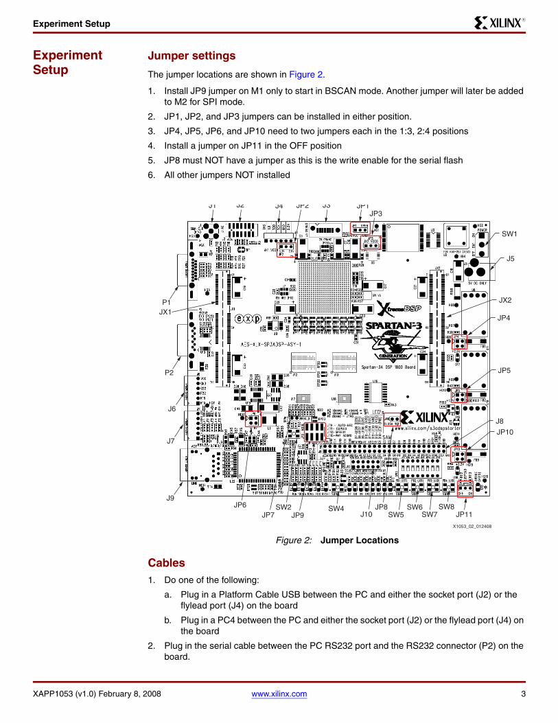
Jumper settings
The jumper locations are shown in Figure 2.
1. Install JP9 jumper on M1 only to start in BSCAN mode. Another jumper will later be added to M2 for SPI mode.
2. JP1, JP2, and JP3 jumpers can be installed in either position.
3. JP4, JP5, JP6, and JP10 need to two jumpers each in the 1:3, 2:4 positions
4. Install a jumper on JP11 in the OFF position
5. JP8 must NOT have a jumper as this is the write enable for the serial flash
6. All other jumpers NOT installed
Cables1. Do one of the following:
a. Plug in a Platform Cable USB between the PC and either the socket port (J2) or the flylead port (J4) on the board
b. Plug in a PC4 between the PC and either the socket port (J2) or the flylead port (J4) on the board
2. Plug in the serial cable between the PC RS232 port and the RS232 connector (P2) on the board.
X-Ref Target - Figure 2
Figure 2: Jumper Locations
SW1
J5
JP4
JP5
JP10
JP11
J9
J7
J6
P2
JX1P1
J10SW8
SW7SW5 SW6 SW4
J1 J2 J4 J3 JP1 JP3
JP2
SW2 JP8 JP6JP7 JP9
J8
JX2
X1053_02_012408

Experiment 1: Create and Test a Bitstream
XAPP1053 (v1.0) February 8, 2008 www.xilinx.com 4
R
3. With SW1 Power in the OFF position, plug in the 5V supply at J5
Files1. Unzip the Xil3S1800ADSP_Rev1_Serial_Flash_v92.zip file to a folder, making sure that
there are no spaces in the pathname.
Experiment 1: Create and Test a Bitstream
This experiment uses a simple Hello World MicroBlaze design that prints to the UART. This experiment will ensure the software, jumpers, and cables are all installed properly. During this experiment, you will create a bitstream for this project and test it by downloading the bitstream directly to the FPGA via JTAG.
1. Select Start → Programs → Xilinx Platform Studio 9.2 → Xilinx Platform Studio to launch Xilinx Platform Studio (XPS).
2. Select File → Open Project. Browse to the Xil3S1800ADSP_Rev1_Serial_Flash_v92 folder, select system.xmp, and click Open.
3. Select the Applications tab which will appear as shown in Figure 3.
4. Right click on Project: hello_world for BRAM initialization, then select Mark to Initialize BRAMs. No other applications should be marked for BRAM initialization.
5. Select Device Configuration → Update Bitstream to generate the MicroBlaze hardware platform, build the Board Support Package (BSP), compile the project, and initialize the bitstream with the application code. The result of this operation is an FPGA bitstream located at:
Xil3S1800ADSP_Rev1_Serial_Flash_v92\implementation\download.bit
6. Launch a HyperTerminal connected to the RS232 COM port with the settings 115200 bps, 8 data bits, 1 stop bit, no parity, and no flow control. Alternatively, double-click on the com1_115200_8n1n.ht file in the project directory to launch HyperTerminal with the appropriate settings.
7. Plug power into the Xilinx Spartan-3A DSP 1800A Starter Platform. Turn the Power Switch to the ON position. The POWER LED should light.
X-Ref Target - Figure 3
Figure 3: Project: hello_world Selected for BRAM Initialization
X1053_03_011608
Experiment 2: Configure From Serial Flash
XAPP1053 (v1.0) February 8, 2008 www.xilinx.com 5
R
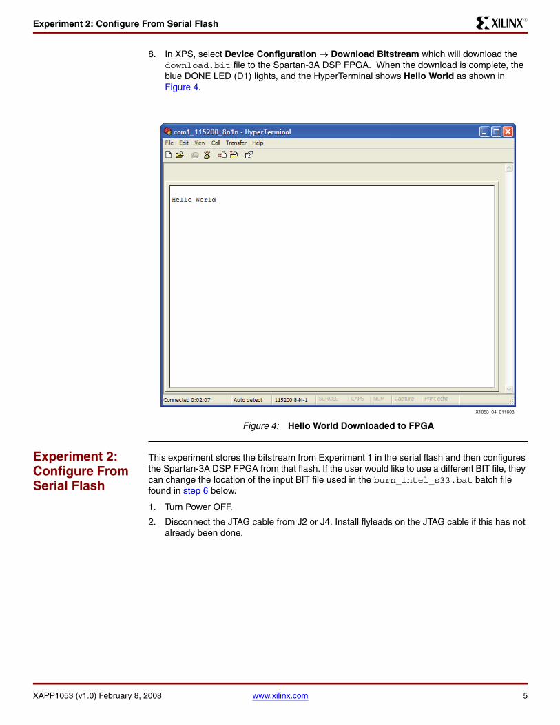
8. In XPS, select Device Configuration → Download Bitstream which will download the download.bit file to the Spartan-3A DSP FPGA. When the download is complete, the blue DONE LED (D1) lights, and the HyperTerminal shows Hello World as shown in Figure 4.
Experiment 2: Configure From Serial Flash
This experiment stores the bitstream from Experiment 1 in the serial flash and then configures the Spartan-3A DSP FPGA from that flash. If the user would like to use a different BIT file, they can change the location of the input BIT file used in the burn_intel_s33.bat batch file found in step 6 below.
1. Turn Power OFF.
2. Disconnect the JTAG cable from J2 or J4. Install flyleads on the JTAG cable if this has not already been done.
X-Ref Target - Figure 4
Figure 4: Hello World Downloaded to FPGA
X1053_04_011608

Experiment 2: Configure From Serial Flash
XAPP1053 (v1.0) February 8, 2008 www.xilinx.com 6
R
3. Plug JTAG cable flyleads onto the SPI connector (J10). Connect the leads as shown in Table 1. Note that as shown in Figure 5, the 2nd row of J10 is not used during this procedure.
4. Add a jumper to JP7 to ground the FPGA PROG_B pin.
5. Turn power ON.
A batch file is provided to simplify the burning of the Intel S33 serial flash using the XIP and iMPACT programs. iMPACT is used in batch mode to convert the bitstream to an MCS file compatible with SPI configuration. XIP is then used to burn this MCS to the Intel S33 flash.
6. Open the burn_intel_s33.bat batch file for editing. If the user would like to use a different BIT file, they can change the location if the input BIT file.
Table 1: Connection of JTAG Cable Flyleads to Board Connector J10
Flyleads Board J10
VREF VCC
GND GND
TCK SCK
TDO MISO
TDI MOSI
TMS SEL
X-Ref Target - Figure 5
Figure 5: JTAG Flyleads Not Connected to Second Row of J10
X1053_05_011608

Experiment 3: Exercise Serial Flash from MicroBlaze
XAPP1053 (v1.0) February 8, 2008 www.xilinx.com 7
R
7. If the PC4 is being used rather than the Platform Cable USB, change the XIP argument from -select_cable 2 to -select_cable 6
8. Close the batch file.
9. Double-click the burn_intel_s33.bat batch file.
10. Verify the programming was successful as indicated by the following statement near the end of batch file command prompt
--> Total byte mismatches [0] (see [verify.txt])
11. Turn off power to the board.
12. Unplug the JTAG cable flyleads.
13. Remove the JP7 jumper to release PROG_B.
14. Place MODE jumpers on JP9 in positions M1 and M2.
15. Turn power on.
Upon power up, the FPGA is configured from the image stored in the Intel S33 Serial Flash. The DONE LED (D1) lights and Hello World is displayed on the HyperTerminal as in “Experiment 1: Create and Test a Bitstream”.
Experiment 3: Exercise Serial Flash from MicroBlaze
A sample application to test the serial flash is included. This application uses the same driver code that is used the user application in “Experiment 4: Bootload MicroBlaze from Serial Flash”. The results are shown in HyperTerminal. The test application does the following:
• Reads the ID of the manufacturer
• Performs a bulk erase
• Writes to all locations in the flash
• Reads from all locations in the flash
1. In XPS, mark the serial_flash_test for BRAM initialization and unmark all others, as shown in Figure 6.
2. Browse through the code to become familiar with what the application is doing.
3. Select Device Configuration → Update Bitstream to compile this project and create a new download.bit bitstream with this application.
Before downloading, make the following changes to the board.
4. Return the JP9 jumpers to Boundary Scan Mode (M1 only installed).
5. Attach a JTAG cable to either J2 or J4.
X-Ref Target - Figure 6
Figure 6: Project: serial_flash_test Marked for BRAM Initialization
X1053_06_011608

Experiment 4: Bootload MicroBlaze from Serial Flash
XAPP1053 (v1.0) February 8, 2008 www.xilinx.com 8
R
6. Turn power ON.
7. If previously closed, re-open the HyperTerminal (com1_115200_8n1n.ht)
8. Download the bitstream to the board.
The test takes less than four minutes to run. The results are as shown in Figure 7.
9. Turn power OFF.
Experiment 4: Bootload MicroBlaze from Serial Flash
This experiment shows how a MicroBlaze application is stored in serial flash device and then bootloaded after configuration. The process to be completed in this experiment is:
• Configure the FPGA from serial flash with a bitstream containing a MicroBlaze hardware platform and BRAM contents initialized with a bootloader application.
• The bootloader accesses a pre-determined location in the serial flash and copies a stored user application from flash to DDR2.
• The bootloader application then jumps to the user application in DDR2 and begins running.
The user application does the following:
• Reads and displays a 16-character location in serial flash and displays the user string.
• Prompts the user to enter a new string
• Accepts a new 16-character string from the UART
• Stores the string in serial flash
• Instructs the how to reconfigure to show that the new string was stored in flash
X-Ref Target - Figure 7
Figure 7: Serial Flash Test Results
X1053_07_011608

Experiment 4: Bootload MicroBlaze from Serial Flash
XAPP1053 (v1.0) February 8, 2008 www.xilinx.com 9
R
This experiment uses the serial flash for three separate functions:
• FPGA configuration
• MicroBlaze application bootloading
• User data storage.
1. Browse through the code for the two applications that are used during this experiment:
a. Project: serial_flash_user_app: A binary version of this application will be stored in serial flash and later bootloaded.
a. Project: serial_flash_bootloader: This application is stored in BRAM and launches immediately after the MicroBlaze is configured.
2. In XPS, mark the Project: serial_flash_bootloader for BRAM Initialization and unmark all others as shown in Figure 8.
X-Ref Target - Figure 8
Figure 8: SPI Bootloader Marked for BRAM Initialization
X1053_08_011608

Experiment 4: Bootload MicroBlaze from Serial Flash
XAPP1053 (v1.0) February 8, 2008 www.xilinx.com 10
R
3. In the Compiler Options window shown in Figure 9, right-click on Project: serial_flash_user_app and select Set Compiler Options… Note that Program Start Address is set to 0x88000000 which is the base address of the DDR2 memory. Click Cancel to close this window.
4. Right-click on Project: serial_flash_user_app and select Build Project. This creates the ELF file Xil3S1800ADSP_Rev1_Serial_Flash_v92\serial_flash_user_app\executable.elf.
Converted this application from ELF to binary format for use with the programming utilities.
5. Select Project → Launch EDK Shell to open a cygwin shell window.
A script is provided for ease of use. The script uses the mb-objcopy utility to convert serial_flash_user_app\executable.elf to FLASH_BURN\serial_flash_user_app.b. Options are included to exclude several initialization vectors which are not used in this application. The syntax format to perform this on the command line of the shell window is:mb-objcopy -O binary <options> <ELF file input> <binary file to output>
X-Ref Target - Figure 9
Figure 9: serial_flash_user_app Compiler Options
X1053_09_011608

Experiment 4: Bootload MicroBlaze from Serial Flash
XAPP1053 (v1.0) February 8, 2008 www.xilinx.com 11
R
6. Type the following command in the shell window:./make_bin.sh <enter>
7. Type exit to close the command shell.
The file serial_flash_user_app.b should be approximately 9 to 10 KB. If the options to exclude the initialization vectors are not used, this file will exceed 500 MB causing the remainder of this experiment to fail.
8. Browse to the FLASH_BURN directory. Make sure that serial_flash_user_app.b fine is 9 to 10 KB in size.
Now the bitstream with the hardware platform and bootloader application is created.
9. Select Tools → Update Bitstream to compile the spi_bootloader project and create a new implementation/download.bit bitstream with the bootloader application initialized into BRAM.
For this experiment, command-line utilities are used to program this information into the serial flash. The bitstream as well as the serial_flash_user_app application binary must be stored in the flash.
10. Browse to the Xil3S1800ADSP_Rev1_Serial_Flash_v92\FLASH_BURN directory
The script used in this experiment is called S3ADSPSK_bootload.bat. The user sets up four variables: bitstream, application, spiPartName, and spi_offset. These variables are already set correctly for this project. To use this script for another project or design, the user must modify the bitstream variable to point to the proper location of the bitstream to be downloaded. The other variables should also be modified as needed. This script accomplishes several things, including:
• Converts the bitstream to the MCS format
• Converts the user application binary to the MCS format
• Combines the bitstream MCS and the user application MCS into a single MCS.
• Erases, program, and verify the flash
11. In Explorer, right-click on S3ADSPSK_bootload.bat and select Edit.
X-Ref Target - Figure 10
Figure 10: Creating Binary of the SPI User Application
X1053_10_011608
Experiment 4: Bootload MicroBlaze from Serial Flash
XAPP1053 (v1.0) February 8, 2008 www.xilinx.com 12
R
Note that the serial_flash_user_app will be stored at address 0x100000 in the serial flash. This is the beginning of Sector #16, which matches the location from which the bootloader application will read (see BOOT_SECTOR constant in the bootload.c file of the serial_flash_bootloader project).
12. Unplug the JTAG cable from J2 or J4 on the board.
13. Plug either the PC4 or USB JTAG flyleads into the SPI port (J10).
14. Add a jumper to JP7.
15. Turn power ON.
16. Double-click the S3ADSPSK_bootload.bat script. The files are converted and programmed into the flash. In the command window, make sure that the device verification was successful:--> Total byte mismatches [0] (see [verify.txt])
17. Press any key to close the command window.
18. Turn off power to the board.
19. Remove the flyleads.
20. If closed, launch HyperTerminal (com1_115200_8n1n.ht).
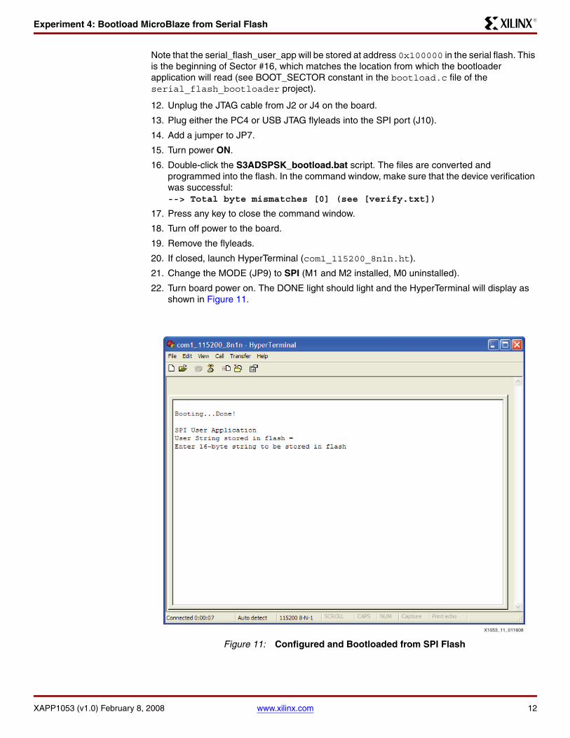
21. Change the MODE (JP9) to SPI (M1 and M2 installed, M0 uninstalled).
22. Turn board power on. The DONE light should light and the HyperTerminal will display as shown in Figure 11.
X-Ref Target - Figure 11
Figure 11: Configured and Bootloaded from SPI Flash
X1053_11_011608

Experiment 4: Bootload MicroBlaze from Serial Flash
XAPP1053 (v1.0) February 8, 2008 www.xilinx.com 13
R
23. Enter exactly 16 characters. For example, 0123456789abcdef. The data is then written in the SPI flash.
X-Ref Target - Figure 12
Figure 12: Initial User String Written to Flash
X1053_12_011608

Revision History
XAPP1053 (v1.0) February 8, 2008 www.xilinx.com 14
R
24. Press the PROGRAM button. The FPGA will again configure from SPI flash. This time, however, the user application finds the string previously typed as shown in Figure 13.
25. Turn the board power off.
Revision History
The following table shows the revision history for this document:
Notice of Disclaimer
Xilinx is disclosing this Application Note to you “AS-IS” with no warranty of any kind. This Application Noteis one possible implementation of this feature, application, or standard, and is subject to change withoutfurther notice from Xilinx. You are responsible for obtaining any rights you may require in connection withyour use or implementation of this Application Note. XILINX MAKES NO REPRESENTATIONS ORWARRANTIES, WHETHER EXPRESS OR IMPLIED, STATUTORY OR OTHERWISE, INCLUDING,WITHOUT LIMITATION, IMPLIED WARRANTIES OF MERCHANTABILITY, NONINFRINGEMENT, ORFITNESS FOR A PARTICULAR PURPOSE. IN NO EVENT WILL XILINX BE LIABLE FOR ANY LOSS OFDATA, LOST PROFITS, OR FOR ANY SPECIAL, INCIDENTAL, CONSEQUENTIAL, OR INDIRECTDAMAGES ARISING FROM YOUR USE OF THIS APPLICATION NOTE.
X-Ref Target - Figure 13
Figure 13: User String Retrieved from SPI Flash
X1053_13_011608
Date Version Description of Revisions
2/8/08 1.0 Initial Xilinx release.