Xicoy X45 TurboJet Engine X45 User manual.pdf+&1& ) /""+ /""+ ) 6"/ /""+ !&, /""+ &)" /""+
28
Xicoy X45 TurboJet Engine User Manual Version 1.2/2020
Transcript of Xicoy X45 TurboJet Engine X45 User manual.pdf+&1& ) /""+ /""+ ) 6"/ /""+ !&, /""+ &)" /""+
Xicoy X45 TurboJet Engine
User Manual
Version 1.2/2020
User Manual X45 Version 1.2/2020
Copyright © 2020 by Xicoy Electrònica S.L. All rights reserved Page 2
Index Index ....................................................................................................................................................................... 2
Features: ................................................................................................................................................................. 3
Legal ........................................................................................................................................................................ 4
Disclaimer ............................................................................................................................................................... 4
Warranty ................................................................................................................................................................. 5
Safety Notes ........................................................................................................................................................... 6
Engine Specifications .............................................................................................................................................. 8
Engine Description .................................................................................................................................................. 9
Battery .................................................................................................................................................................... 9
Fuel ......................................................................................................................................................................... 9
Oil .......................................................................................................................................................................... 10
Installation Notes ................................................................................................................................................. 10
Component Description ....................................................................................................................................... 12
ECU (Engine Control Unit) ................................................................................................................................. 12
Connector board, the “Hub”. ............................................................................................................................ 13
Fuel Pump ......................................................................................................................................................... 13
ECU Display ........................................................................................................................................................... 15
Engine Installation: Electrical connections ........................................................................................................... 16
ECU setup ............................................................................................................................................................. 17
Aligning transmitter with ECU .......................................................................................................................... 18
Telemetry.............................................................................................................................................................. 19
Preparing the engine for running ......................................................................................................................... 20
Important notes for kerostart engines: PLEASE READ ........................................................................................ 20
During startup ....................................................................................................................................................... 20
First engine runs ................................................................................................................................................... 21
Starting the engine ............................................................................................................................................... 21
Engine shut down procedure ............................................................................................................................... 22
WHAT TO DO IN THE CASE OF AN EMERGENCY .................................................................................................. 22
Adjusting the engine maximum power ................................................................................................................ 22
Autorestart function ............................................................................................................................................. 22
Restart options and how to enable them: ........................................................................................................ 23
What the auto-restart function does: .............................................................................................................. 23
User Manual X45 Version 1.2/2020
Copyright © 2020 by Xicoy Electrònica S.L. All rights reserved Page 3
What the Autorestart function will not do: ...................................................................................................... 23
When should Autorestart function be enabled? .............................................................................................. 24
Throttle curves ..................................................................................................................................................... 25
Acceleration and deceleration settings. ............................................................................................................... 25
Exhaust tubes ....................................................................................................................................................... 26
Use in gliders and in 3D planes............................................................................................................................. 26
List of ECU message codes ................................................................................................................................... 26
Diagnoses .............................................................................................................................................................. 27
Diagnosis messages: ......................................................................................................................................... 27
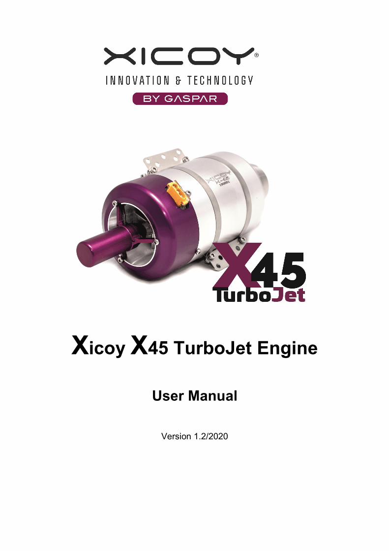
Congratulations on your purchase of this new generation Xicoy “X45” gas turbine engine. We are confident you will be pleased with your purchase and your new engine will give you excellent service and maximum enjoyment to your hobby.
The “X45” engine is the result of a very extensive research and development programme by Xicoy Electronica SL supported by the latest fluid dynamics and analysis software to bring you an engine of unparalled performance and incredible response in an amazingly small package. New electronics design and digital programming sets a new high bar standard for this new generation of small jet engines.
Features:
45N / 10lb of thrust in a tiny 60mm case
Low Idle thrust just 1.8N / 6.5oz
Low weight of 395g / 14oz
Valves installed on-engine
ECU mounted on engine
Internal kero burner and thermocouple for clean exterior
Compatible with diesel and kerosene
Typical start to idle of just 25secs
Fast spool up to max rpm
Super-fast auto-restart with normal and glider modes
Automatic cooldown after run with receiver power turned off
Automatic power-off after cooldown
Automatic adjustment of engine performance from ambient pressure and temperature.
Brushless high speed starter
Intelligent brushless fuel pump
High speed digital control of all components
Neat slip-on FOD screen included
User Manual X45 Version 1.2/2020
Copyright © 2020 by Xicoy Electrònica S.L. All rights reserved Page 4
Choice of display options, on and off board and Bluetooth Android/iPhone
Telemetry options available for most modern transmitters
New options are being added from time to time,
Keep watching on: www.xicoyturbines.com for details
The Xicoy Electronica SL responsibility is limited exclusively to the repair of the engine and accessories which are outlined in the conditions of warranty.
Before unpacking the engine, please read through these notes and agree to the conditions of warranty.
Customer satisfaction is important to Xicoy Electronica. Technical support is readily available through your local dealer and via email:
Xicoy Electronica SL, Plaça Pere Llauger Nau 18, 08360, Canet de Mar, Barcelona, Spain
Web site: www.xicoy.com Email: [email protected]
See our new turbine webpage at: www.Xicoyturbines.com
Legal
The engine design and contents of this User Manual are copyright Xicoy Electronica SL, Canet de Mar, Barcelona, Spain. All rights are reserved.
This User manual, pictures and data are the property of Xicoy Electronica SL and cannot be used or reproduced in any way with written permission from Xicoy Electronica SL.
Disclaimer
This X45 engine is a very sophisticated piece of machinery. Great care should be taken at all times when using the engine. It should only be operated by those with appropriate skills and knowledge to do so. The engine is not a toy. Incorrect operation or misuse can cause damage to property and bodily harm to operators, spectators or animals. Xicoy Electronica SL accepts no liability any damage which may occur.
Xicoy Electronica SL assumes no responsibility for any errors contained in this document and is not liable for any damages resulting from such errors.
It is forbidden to use this engine outside radio control applications, especially those that power vehicles to carry people.
User Manual X45 Version 1.2/2020
Copyright © 2020 by Xicoy Electrònica S.L. All rights reserved Page 5
Warranty
The warranty duration for this Xicoy X45 engine is two years from date of completed purchase, or 25 running hours, whichever comes first. Warranty is valid solely for the original 1st owner and is non-transferable upon resale. Warranty includes all supplied parts and is limited to manufacturing defects only. Shipment costs forth and back, including packing and relevant customs fees are not covered by the warranty, and will be at owner’s expense.
Damage or defective operation covered under warranty terms will be repaired and tested at no cost to original owner (other than shipping expenses). Repairs not covered under the terms of warranty will be carried out by Xicoy Electronica SL or their appointed agent after agreement of costs.
Before returning the engine or ancillary equipment for service or repair, please contact first your local dealer or Xicoy Electronica SL central office to agree action and costs.
Do not ship before contacting Xicoy Electronica first.. Shipping anything from outside the EU without appropriate documentation will introduce delay and costs at customs borders.
Please do not disassemble this engine or accessories (pump etc.). You will breach your warranty agreement and will find it an unfamiliar sophisticated and precision assembly which you may not be able to reassemble without considerable difficulty and specialist equipment.
Simply slackening the compressor nut on the engine will lose the delicate balance condition of rotor without which the engine may not run without sustaining damage to the rotating assembly.
This warranty is voided if any one or more of the following conditions applies. In such a case Xicoy Electronica SL will accept no responsibility for any damage or other consequence caused by engine operation.
1. The product has been subject to any form of operation using incorrect fuel, oil or fuel/oil mix.
2. The product is, or appears to be, crash damaged, the fuel pump is blocked due to particle ingestion,
electronics or pump-drive are flooded with fuel or water ingress, connection leads are cut or show loss of
insulation and/or short circuit, overvoltage, or reverse polarity on battery or engine cable connection.
3. Unauthorized maintenance and/or modifications have been made to any part of the product; including
unlocking of the ECU and changing any of the manufacturers settings, or any items supplied has or appears to
have been disassembled.
4. Parts show damage by ingestion of foreign object (wires or pipes, sand, grit and small abrasive
particles, water or fluids, dry powder from extinguisher, etc.).
5. The engine has or appears to have been operated incorrectly or not in accordance to this operators
manual.
6. The product has been or appears to have been misused, neglected or inadequately maintained.
7. The engine or fuel pump has or appears to have suffered damage or blockages in the fuel system due
to being run with unfiltered or contaminated fuel.
8. The engine and/or accessories show damage by physical contact with a corrosive substance through
operation or storage.
9. The engine has been used in 3D planes.
User Manual X45 Version 1.2/2020
Copyright © 2020 by Xicoy Electrònica S.L. All rights reserved Page 6
Safety Notes
Please remember that though this engine is very small and bijou it is most definitely NOT a toy and has the potential to hurt you or others around you if misused. The engine is a very high performance machine in miniature and must always be treated with a high level of care and safety when in your operation. It is your responsibility as owner, to ensure safe and considerate operation at all times and conforming to the word and sprit of this User Manual. By running this engine you agree to assume full responsibility for its safe operation.
If you sell or transfer this engine, please pass this User Manual or web link to the new owner.
The following guidelines should be read carefully and followed:
Always keep a C02 or similar gaseous fire extinguisher of at least 2kg contents close to hand when
starting and operating the engine. Do not use a powder extinguisher unless of last resort as the powder will
ruin the engine if it used.
Protect eyes and ears during the starting procedure.
Be especially aware this engine is very fast to start, initiate only when ready.
Please note this engine is extremely fast to spool to maximum thrust, use the throttle control carefully,
especially with very small models.
Be aware of the extreme intake suction, use the available and supplied intake filter screen always.
Always run the engine in open air as engine exhaust contains gases which can cause asphyxiation and
nuisance smells.
The engine WILL be very hot while running, so please don´t touch it.
Keep clear anything affected by heat away from the engine, especially the exhaust area.
Don´t run the engine anywhere near a source of flammable gases, liquids or materials.
Don´t run the engine or fly the plane in wooded or crop or other high fire risk areas.
Keep spectators, children and animals clear of starting area (10mtrs (30ft) radius away).
Always handle turbine fuel and oil with care as they are flammable and can cause a reaction with
sensitive skin. Store them in clearly marked containers and always dispose appropriately. Use protective
gloves when mixing and decanting fuel and oils. Avoid all skin, eye, mouth or ingestion contact with the liquids
and ensure any spillage is wiped up immediately. Clean any affected area with warm soapy water. Wash
hands and any effected part immediately after any contact.
Continued excess of fuel priming or failure of the internal burner to initiate the combustion can result in pooling of fuel inside the engine which could cause excess flaming in event of subsequent ignition. The only method to clear the engine is to tip it forward and allow excess to escape through the front of the engine. Mop up with a rag. Tipping it backwards will not work as the internal construction of the engine prevents any liquid draining out to the rear.
This engine is a real gas turbine machine with very high rotational speeds and high temperature fast moving exhaust gases. Despite the small intake the engine is able to swallow a huge amount of air, and anything else that air can carry with it. So before running please carefully check the area surrounding the front and back end of the engine for any loose materials like rags, sawdust, sand or grit, modelling materials, liquids, or anything else that can be picked up by the airstream and sucked into the engine, or blown out at speed by the exhaust.
User Manual X45 Version 1.2/2020
Copyright © 2020 by Xicoy Electrònica S.L. All rights reserved Page 7
If you are new to turbines or returning after some years it is a good idea to set up the engine on a simple test stand so you can get familiar with its operation before installing it into a model. Use a maximum thrust setting that is appropriate for your model especially on 1st flights. The RUN menu shows this clearly, see “derating”. A power/weight ratio of 1:1 sounds great but can accelerate a model dangerously quickly and can lead to control or structural failure of the model. If you have recent jet engine experience you should be able to install the engine straight into your model but take careful note of the quick response in start-up and throttling. Every engine is carefully test run at the factory together with the all its ancillary items (pump, cables, etc) to ensure that the whole system performs properly, so you can take confidence to know it is fully operational at time of despatch.
Being an internal combustion engine the engine will consume oxygen during running so must never be run inside or in a confined space. The engine consumes a volume of air about 93ltrs/3.3cu ft every SECOND (ie, a dustbin full) so can quickly use up a lot of air in a limited space, so only run outside in open air. Never try to slow the engine by placing any kind of restriction on the intake or the exhaust or on the model. The suction is more powerful than any vacuum cleaner and can do severe damage to anything passing into the intake. It can also collapse an airframe where insufficient area for the intake air is provided, or is restricted in some way. The small fod screen supplied is intended to prevent small articles being drawn into the engine like blades of grass, small stones etc. It cannot prevent a rag or similar being accidentally jammed against the front of the engine by the suction, so please take great care. Never test the suction with fingers or hand, these engines bite hard.
The engine exhaust exit is very small but with such a large volume of gas passing through it at pressure it makes a loud penetrating noise. At a distance this noise is most pleasing but in close proximity (within 5mtrs/16ft) the noise level can be very hazardous to hearing so always ensure you and any nearby helpers have proper ear defenders and are wearing them while test running the engine. Ensure you check carefully the area where you plan to run the engine and have someone keep lookout for inquisitive bystanders who could approach to see the source of the noise, as you will be concentrating on the engine. Agree a system of hand signals in advance so they know what you are planning to do and can warn you of any issue during the run, ie shut down in a hurry or reduce to idle if someone (or an animal) is approaching, walking by, etc.
The engine has its own internal starting system and does not require any assistance or priming to operate. So please do not try to assist it to start quicker or easier by administering any flammable agents, sprays or similar, into the engine in the belief it will start better. It won´t, but it could result in causing a dangerous flashback or fire to start which could rapidly get out of control and putting yourself in danger or more surely the destruction of your model. The engine does not need priming like a petrol or glow engine to start, so when filling the fuel line for the first time leave a couple of cms of empty pipe where it connects to the engine to be sure you have not pushed a puddle of fuel into the engine which can cause a flame on start-up.
The engine has been tested at factory with the cable connector facing upwards and the fuel inlet below. But if it suits your installation better the engine can function safely in any orientation which suits your installation, but you will find starting is quickest and easiest with the recommended positioning. If you find the engine cable length is not sufficient for your installation, please do not cut it and try to extend it, please get in touch with the Xicoy office for a longer version.
The engine has a replaceable 6V internal starting burner. This is an Authorised Dealer and/or Service Agent replaceable component as the engine must be opened to access it. Note - unauthorised opening of the engine will void the warranty. The burner has been designed that the rotor is not disturbed during this process so the balance is retained. The engine also features an internal thermocouple. This avoids the danger to this delicate component being outside the engine from the usual knocks and bumps associated with engine install and refit.

User Manual X45 Version 1.2/2020
Copyright © 2020 by Xicoy Electrònica S.L. All rights reserved Page 8
If the thermocouple needs attention please refer to nearest Service Agent or direct to Xicoy Electronica SL as the engine case requires opening to access it.
The engine starter is a high quality high speed brushless unit. The power driver for this is part of the ECU. It should go without saying you cannot replace this with anything else. You also cannot power the starter separately beyond using the “starter test” function. The starter is accessible and in the unlikely event of attention can be easily replaced. The small clutch fitted to the starter motor has a small O-ring which may wear in service. It is easily replaced if required.
Please note that the accessories used for this engine use the simple 3-wire servo type cable connection. This includes the fuel pump, display, sensors, telemetry adapters etc. In all cases the third wire (usually orange or white) is a digital signal line so DC power should not be applied to this line or attempts made to read the voltage on this line for fault-finding purposes.
Please refer to the Xicoy office for guidance in the first instance in event of any issue.
Engine Specifications
Engine diameter 60mm / 2.35”
Length 160mm / 6.3”
Engine weight 398g / 14oz
Total installed weight 470g/16.5oz
Nominal thrust at sea level 45N / 10lbs (continuously derateable to 20N / 4.5lbs)
Idle thrust 1.8N / 0.4lbs
Max rpm 225,000
Idle rpm 60,000
EGT at max thrust 550 -700´C
Fuel consumption at max thrust 140g / 4.7oz per min
Minimum exhaust tube diameter 45-50mm / 1.8-2”
Glow plug volts 6v
Restart capable, 2 modes, manual (glider) & automatic
Fuel / Oil, Kerosene or diesel + 4% oil mix. See text for breakdown
*The specifications may be subject change without notice as new updates and developments are added to the production model.
User Manual X45 Version 1.2/2020
Copyright © 2020 by Xicoy Electrònica S.L. All rights reserved Page 9
Engine Description
The engine is a miniature turbojet design produced specifically to produce thrust to power small model aircraft. It has a single stage billet machined centrifugal compressor and single stage cast Inconel axial flow turbine mounted on a single shaft. The engine is fitted with a long life ceramic glow plug which enables the engine to initiate combustion directly on liquid fuel after which further fuel is gradually introduced into the main part of the combustion chamber to provide combustion heat to operate the engine. A high speed brushless electric starter motor fitted with a clutch mechanism to the front provides drive to the rotor up to self-sustaining speed for starting the engine. The starting sequence is controlled by an electronic system fitted to the engine (ECU) which initiates the start sequence and controls the parameters of the engine within design limits.
The engine rotor shaft is supported by two ceramic bearings which are lubricated by a small percentage bleed off the pressurized main fuel supply, which should contain a small percentage of oil for this purpose. The rotor discs are separately balanced and then 2-stage dynamically balanced on assembly to the engine. Disturbing the rotor will lose this delicate balance and the engine will need to be returned to a service unit for rebalancing.
The fuel for the engine is provided from a fuel tank and fed through a small pump driven by a 3-phase (brushless) motor that has its own intelligent control. The engine speed between idle and maximum is controlled by varying the speed of the fuel pump rotor by command from the electronic device called an ECU (Electronic Control Unit) that is mounted under the front cover of the engine. This sends commands to the fuel pump via a connector board (Hub) to turn at a certain rpm (and therefore flow rate) to deliver a precise amount of fuel and the fuel pump automatically adjusts itself to this rate. The communication between the ECU and fuel pump and all other function accessories, display, telemetry etc is via a single wire bidirectional digital data link, no analogue voltages are used and operation is not voltage sensitive.
To control the admission of fuel to the burner and main combustion chamber there are two miniature electric valves attached to a mounting block fitted to the front of the engine, under the cover. This block also holds the 4mm quick-release fuel feed connection. The valves are connected to and controlled by the ECU as required by the starting sequence. The valve block assembly is replaceable but the individual valve assemblies are not user serviceable.
Battery
The engine has been designed to use a 2s Lipo battery for power. 3S LiFe batteries are allowed in the case that Lipo can’t be used, but if possible, use 2s Lipo. Using a higher battery voltage than 10V will damage the ecu.
Use at least 25C batteries. Do not use other battery types like LiIon, these batteries cannot deliver the peak amperage (20A) necessary for starting.
The engine uses about 100mAh for starting, about 20mAh for each minute running, and about 40mAh for cooling after a run.
Fuel
The engine can be run using Kerosene or Diesel fuel. Kerosene is the recommended fuel if available; it produces the best user experience, as the engine starts and accelerates faster, without smoke, flames or
User Manual X45 Version 1.2/2020
Copyright © 2020 by Xicoy Electrònica S.L. All rights reserved Page 10
unpleasant smell. Diesel fuel is acceptable, the engine will not be damaged by using it, but user experience will be worse. Power is the same using both fuels.
Recommended Kerosene fuel is the odourless refined Kerosene (some countries call it ”Paraffin”) used in home stoves, there are different commercial brands like “keroclair”, “Ptx200”, “Petroleum”.as it is very clean and burn without smell. JetA1 will work the same but should be carefully filtered before use, but its odour can be offensive during model storage.
Oil
A 4% of oil should be mixed with the fuel. The recommended mix is a 3% of ISO32 type of oil, commercial brands like Mobil DTE lite, Shell Tellus 32, Igol 32, Cepsa Turbine 32, etc) plus 1% of 100% synthetic 2 stroke oil. Plenty of commercial brands available locally, just check in the bottle that the oil is JASO FC or JASO FD compliant. Commercial turbine oils like Kingtech oil, Jetcat oil, Jackadofsky oil, Fuchs, Deluxe… can be used.
It is allowed to use a 5% of oil contents for compatibility with other engine brands, this will cause a higher fuel consumption and increased possibility of internal carbon building. Full size turbine oils can be used, but are not recommended because these oils are not intended to be burned, irritant and contains neurotoxic chemicals such as tricresyl phosphate that in long term could impact negatively on the health of operators and other persons breathing the exhaust fumes. Aeroshell 500 should not be used at all due at high residues left on bearings
Do not use 2 stroke oil alone (4%). This will gum the bearings causing difficult or impossible startup when engine be cold.
Installation Notes
1. The engine should be mounted securely using only the strap mount supplied.
2. The 3-wire connecting cable from the engine to the connector board should be carefully routed away
from the engine intake so there is no possibility of the wire being accidentally ingested if the FOD screen
should be displaced for any reason. Avoid placing the cable close to the engine rpm sensor which is located at
approximately 4 O´clock when viewed at the front of the engine with the cable entry plug at 12 O´clock. A
cable too close can cause some rpm interference at start-up. The same goes for any servo wires passing
near.
3. The 4mm fuel feed pipe should be routed similarly clear of the intake.
4. The other end of the engine cable should plug into the Hub sited at a convenient location for access.
This is also the location to connect the ECU battery. If battery is sited at some distance perhaps in the nose of
the aircraft, please contact Xicoy and ask for a longer cable in one piece. Please don´t cut it and splice in a
couple of old bits of wire to make it longer. A heavy duty extension can be used but check polarity before
plugging in. It’s always better to have a longer single piece cable for minimum volt drop and maximum
reliability.
User Manual X45 Version 1.2/2020
Copyright © 2020 by Xicoy Electrònica S.L. All rights reserved Page 11
5. The centre of the fuel tank should be located as close to the centre of gravity (CofG) of the model as
possible. This will minimize the effects of the CofG shifting as the fuel is used during the flight. The fuel tank
should have an effective fuel pickup, like a felt clunk or felt bag over a weighted clunk to ensure no air is pulled
into the fuel feed.
6. The fuel pump should be located close to the fuel tank as convenient. Fit the inline filter between tank
and pump to protect the pump from particles that could jam the pump. The pump has two 3mm screw fixing
holes provided for mounting to the airframe.
7. Run a single piece of tubing between the pump and the engine. Do not install anything (valves, filters,
flowmeters… ) between the pump and the engine.
8. If using “Tygon” flexible piping from fuel tank push on a short (12mm/1/2”) length of the supplied 4mm
pipe onto the pump suction port and push the “Tygon” over the top to provide a tight leak free fitting. A double
wrap of lock-wire will ensure secure connection. Otherwise, use the 4mm piping supplied.
DO NOT use nylon tie wraps anywhere on the fuel system.
9. DO NOT use “Tygon” flexible piping anywhere for the pressure (delivery) side; it is only suitable on the
suction side. Also DO NOT use silicon tube anywhere in the fuel system as the fuel will melt it.
10. Any air ducting to the engine inlet should have sufficient diameter of at least the engine case diameter
(60mm / 2-1/2”).
11. If an extended exhaust duct (internal tailpipe) for internal installation is required, it should be 45 to
50mm (1.8-2”) diameter and stiff enough to resist flattening in the airflow. Leave a gap of 25mm (1”) from tip of
the exhaust to the end of the duct (excluding bell mouth length).
12. Extreme care should be taken to avoid the possibility of foreign objects, loose parts or debris being
allowed to enter the compartment where the engine is installed. Always use the supplied FOD screen but
regard this as a last line of defence and not as a reason not to practice good housekeeping. Before filling the
tank and starting the engine for the first time, turn the model upside down and give it a good shake to loosen
and clear any small bits and pieces lying in the engine compartment. A go-around with the hoover is also a
good idea.
13. We recommend testing the engine on a test stand prior to fitting to an airframe.
14. You should have a clear idea how to arrange all the components needed to run the engine inside the
model. The main issues are fuel tank (locate centre of tank to CofG), bubble trap position (if used), locating the
fuel pump in close proximity to the source of the fuel (bubble trap or tank) and adjusting the receiver and ECU
batteries to achieve optimum location for balancing the model.
15. Do not under any circumstances try to run the fuel pump by plugging it into any other FADEC
brushless pump control or similar type 3-phase driver. It does not work like that and you will destroy it in the
process.
User Manual X45 Version 1.2/2020
Copyright © 2020 by Xicoy Electrònica S.L. All rights reserved Page 12
Component Description
ECU (Engine Control Unit)
The ECU and indeed the whole system used on this engine are totally new and unlike any previous version of Xicoy ECU. It is a new controller developed specifically for this application by Xicoy Electronica which is in the form of a small C-shaped pcb fitted under the front cover of the engine. It is connected via the 3-wire cable which plugs into the engine and to a small connector board called the “Hub” externally. The three wires are just plus (+) minus (–) and data. The signals in and out of the ECU are via bidirectional digital data link, no direct connection to the outside world is required, or possible.
The ECU is a powerful new design using a completely new architecture than used before, so represents not an upgraded version of anything before but a new system completely. This new platform allows us to break from the limitations of older technologies to make use of the latest high speed connectivity to add many more functions than were possible before, and all using a single wire data cable. All signals in and out of the ECU go via the Hub which acts as a clearing house for ECU data and the outside world.
The ECU is programmed specifically for the X45 with the engine operating characteristics, start parameters, throttle curves and operating routines. Some of these are user settable like the radio setup and maximum thrust settings which are accessed used via a menu system on a special data display which plugs into the Hub. A version of the Hub is available with a display built in and with adjuster buttons which you can mount in your model, to eliminate the need to plug in anything. The screen is very bright making it easy to observe the start-up on the display from a short distance through a canopy, for instance.
Users familiar with other Xicoy ECUs will notice the menu structure is very similar to previous generation ECUs, but with some display items in new positions, some extra functions added and some removed. This is mainly because the ECU is specially produced for the X45 so functions which have previously been general purpose are now tuned specifically for the engine and fixed.
We have added a few new special options:
Kero/Diesel selector: This option switches between pre-set routines for each fuel. This saves you the ordeal of having to make many adjustments to fine tune the starting every time you switch fuels, now you just press a button to click your fuel, and go. Diesel being heavier and higher flashpoint fuel than kerosene requires a different start technique to enable it to start quickly and cleanly. We have spent time optimizing the engine for each fuel and have prepared two start routines. You choose the fuel option and leave the ECU to use its pre-set start routine.
Power adjustment: To limit the engine to a reduced maximum rating there is a simple setting in the RUN menu which shows maximum rpm with a corresponding nominal thrust figure. So it is easy to dial in say 35N (8lbs) without having to know the rpm setting for this. This adjustment is operative between 20N (4.5lbs) and maximum.
Battery recognition. Another addition is automatic detection and accommodation for 7.4v LiPo and 9.9v 3-cell LiFe batteries. The ECU detects the battery voltage at plug in, and automatically adjusts the starter maximum rpm to make use of the additional voltage available
Ambient Auto-Tunning: The hub board includes an ambient pressure sensor and an ambient temperature sensor. This data is used by the ecu to adjust the acceleration/deceleration rates and idle speed at the

User Manual X45 Version 1.2/2020
Copyright © 2020 by Xicoy Electrònica S.L. All rights reserved Page 13
optimum values automatically. This function is available on engines with software version 8.03 or higher that have a sensored hub.
The heart of the ECU is one of the latest high speed microprocessors which enable it to carry out millions of instructions per second and do a great many things at the same time without having to stop and wait. It has its own memory so can hold programme instructions and operating data and store runtime data from previous engine runs.
Connector board, the “Hub”.
To enable connection of the power supply and signals to and from the outside world to the ECU, a small connector board which we call the “Hub” is provided. This forms the connecting point for:
The receiver throttle signal (max voltage 10v) ECU battery (volts 7.4 – 10V) Fuel pump ECU on the engine Any display used, either on board as part of the connector board (compact version) , or separately plugged in (Light version). Additional input sensors such as pitot pressure, rpm from a 2nd stage, etc Additional output devices such as telemetry, SD memory storage, Bluetooth etc.
The Hub has some intelligence of its own in that it can take a signal from the ECU and isolate (power down) the ECU battery after a cooldown has completed and the receiver turned off. The ECU will complete the cooldown process even if the receiver is turned off, it does not need a radio signal to do this. This saves the battery in the transmitter and receiver and helps stop the possibility of leaving them on for long periods accidentally.
From engine S/N 100, the hub includes one ambient pressure sensor and one ambient temperature sensor.
The Hub is available in two options, the simplest being the smallest option which is plain board to connect ECU battery, receiver, ECU, fuel pump and a full colour external display. This is ideal for the smallest installation, small foamies etc. Others will have a display or indicator lights included on the board, or with Bluetooth connectivity included, or other options. The Xicoy website: www.xicoyturbines.com will show what is available for the X45 at any time, new items are being added regularly.
The Hub has a printed panel showing where each cable goes and the orientation of each plug. For all cables, if you need a longer or shorter version than supplied, please contact Xicoy. Do not cut or splice in extra wire.
Battery should be connected directly to the Hub, not using switches, electronic regulators, diodes etc. Multiple battery operation using “Y” lead is possible but at least one battery must be directly connected.
If you are using the full colour, plug-in display this is also plugged in here.
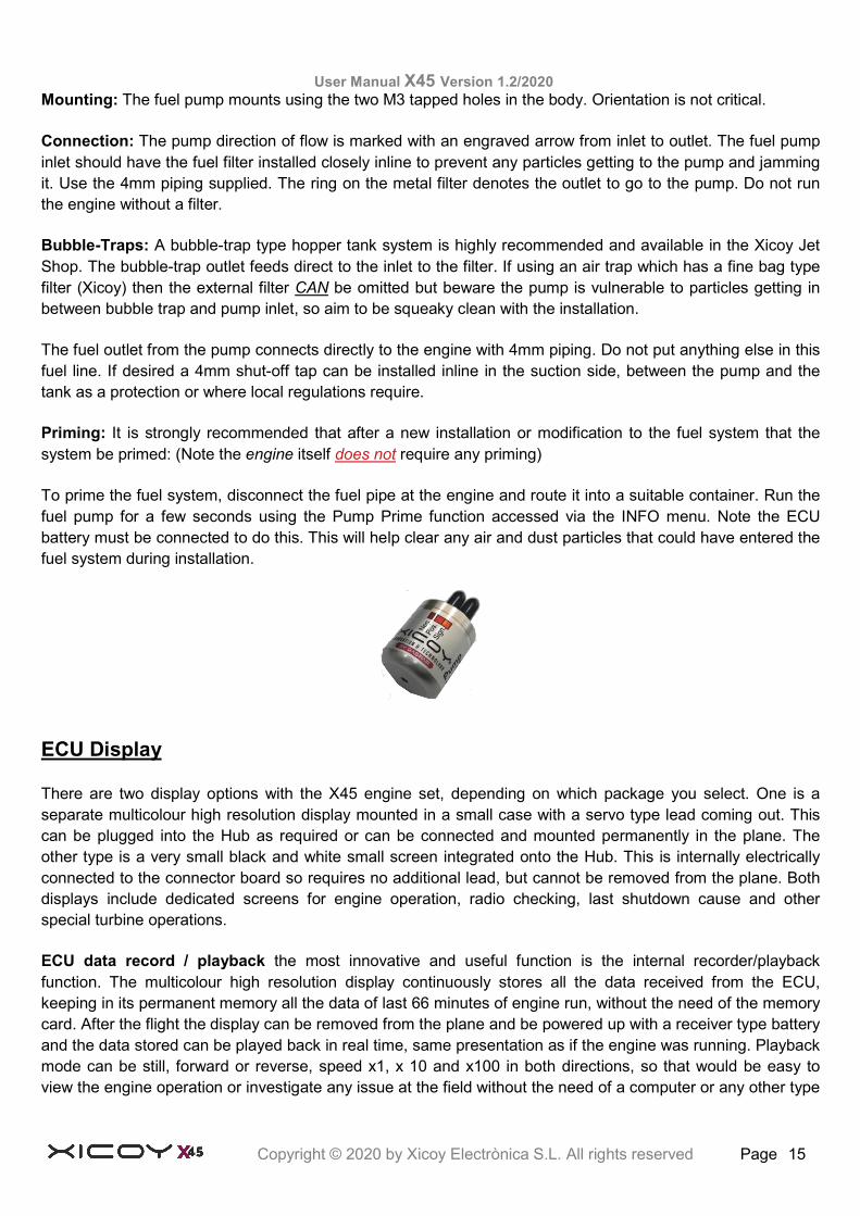
Fuel Pump
As mentioned previously, the fuel pump has been specially designed for this application and is unique in many ways. It is extremely small in size and weight but is much more sophisticated than its looks suggest. There is
User Manual X45 Version 1.2/2020
Copyright © 2020 by Xicoy Electrònica S.L. All rights reserved Page 14
not the usual fixed cable with socket but a small plug built into the pump which enables a regular high quality JR type servo cable to be used as the pump cable (socket at both ends). This way it’s easy to get just the right length you need without cutting or extending the wire.
Note: the three wires are NOT the 3-phases usually used for a brushless motor. The three wires are for the plus and minus power supply, and a single wire bidirectional digital link.
Construction. Inside the sturdy machined aluminium housing is a powerful, purpose made brushless (3-phase) motor with a ball raced (not plain bearing) shaft carrying a pair of precision close tolerance gears to provide the displacement pump function. A pair of nipples provides a secure connection for 4mm piping at inlet and outlet. Two tapped holes in the body provide a secure mounting location avoiding the need for tie-wraps and other messy fixings, for a neat and tidy installation. Never try to disassemble the pump, it has an extremely delicate internal structure and you will void its warranty.
Operation: The difference between this pump and most others is that it also has its own tiny brushless 3-phase driver included within the pump housing. The motor is not a slave to an external driver or an open loop dc motor driven by an external voltage, but has its own sophisticated controller and driver built in. This controller communicates with the ECU via the Hub many hundreds of times a second. The ECU sends out an rpm request to the pump and receives actual rpm information and therefore flow rate return signals back, and this process is updated continuously at high speed.
Please note, you must not try to run the pump by plugging this 3-wire cable into any brushless (3-phase) driver, the controller will be immediately destroyed.
This system means the ECU does not have to spend time constantly controlling the pump speed, it only needs to send a brief signal to request a certain rpm. The on board controller then looks after how this command is carried out and confirms it back when this is achieved. This enables the ECU to do other things like updating telemetry or collecting data from sensors, while still controlling the engine operation.
Pre-setting: The pump initial flow rate is set at the factory with the engine, by simply setting the minimum rpm it produces sufficient heating from the burner for a start. This is the only required adjustment. Once set, the user needs make no adjustment to pump commands. Being based on a brushless motor it does not suffer from sticky seals or variable speeds due to atmospherics or fuel densities unlike regular DC motor based pumps. So the old juggle with adjustable “pump start point” is no more. To accommodate the idealising of the start process required for kero and diesel fuels we have pre-programmed in an optimised sequence for each, activated by a simple switch in the START menu. Select the fuel type you are using and the ECU does the rest.
Replacement pump pre-set. In event of the pump needing replacement for any reason the user can set the new pump to the default setting (100 rpm) and see the heating effect on the engine on a start. If slow to heat up then the value can be raised to the next level (125) and so on until a satisfactory setting is found. There are a limited range of values, with jumps of 25 between each so the process is quick and straight forward. Once set, this value can be left and does not usually need adjusting in normal use. All other start functions are handled automatically by the ECU.
Applying a DC voltage to the fuel pump will not make it run so please do not try it. Modifying the cable and reverse connecting the polarity of the power supply wires will also not make it run but may destroy the internal pump controller, so don´t risk ruining your pump by modifying your cable, just get the right length you need.
User Manual X45 Version 1.2/2020
Copyright © 2020 by Xicoy Electrònica S.L. All rights reserved Page 15
Mounting: The fuel pump mounts using the two M3 tapped holes in the body. Orientation is not critical.
Connection: The pump direction of flow is marked with an engraved arrow from inlet to outlet. The fuel pump inlet should have the fuel filter installed closely inline to prevent any particles getting to the pump and jamming it. Use the 4mm piping supplied. The ring on the metal filter denotes the outlet to go to the pump. Do not run the engine without a filter.
Bubble-Traps: A bubble-trap type hopper tank system is highly recommended and available in the Xicoy Jet Shop. The bubble-trap outlet feeds direct to the inlet to the filter. If using an air trap which has a fine bag type filter (Xicoy) then the external filter CAN be omitted but beware the pump is vulnerable to particles getting in between bubble trap and pump inlet, so aim to be squeaky clean with the installation.
The fuel outlet from the pump connects directly to the engine with 4mm piping. Do not put anything else in this fuel line. If desired a 4mm shut-off tap can be installed inline in the suction side, between the pump and the tank as a protection or where local regulations require.
Priming: It is strongly recommended that after a new installation or modification to the fuel system that the system be primed: (Note the engine itself does not require any priming)
To prime the fuel system, disconnect the fuel pipe at the engine and route it into a suitable container. Run the fuel pump for a few seconds using the Pump Prime function accessed via the INFO menu. Note the ECU battery must be connected to do this. This will help clear any air and dust particles that could have entered the fuel system during installation.
ECU Display
There are two display options with the X45 engine set, depending on which package you select. One is a separate multicolour high resolution display mounted in a small case with a servo type lead coming out. This can be plugged into the Hub as required or can be connected and mounted permanently in the plane. The other type is a very small black and white small screen integrated onto the Hub. This is internally electrically connected to the connector board so requires no additional lead, but cannot be removed from the plane. Both displays include dedicated screens for engine operation, radio checking, last shutdown cause and other special turbine operations.
ECU data record / playback the most innovative and useful function is the internal recorder/playback function. The multicolour high resolution display continuously stores all the data received from the ECU, keeping in its permanent memory all the data of last 66 minutes of engine run, without the need of the memory card. After the flight the display can be removed from the plane and be powered up with a receiver type battery and the data stored can be played back in real time, same presentation as if the engine was running. Playback mode can be still, forward or reverse, speed x1, x 10 and x100 in both directions, so that would be easy to view the engine operation or investigate any issue at the field without the need of a computer or any other type
User Manual X45 Version 1.2/2020
Copyright © 2020 by Xicoy Electrònica S.L. All rights reserved Page 16
of reader. All the data, including all engine parameters, can be saved later to a memory card, where it can be read using a text editor, or our viewer software. Also this data can be sent to Xicoy to be studied.
The function of the buttons is described later in the “ECU setup”
In the case that the touchscreen is not responding as required, you can recalibrate it. Power-up while touching the centre of screen, and follow the instructions.
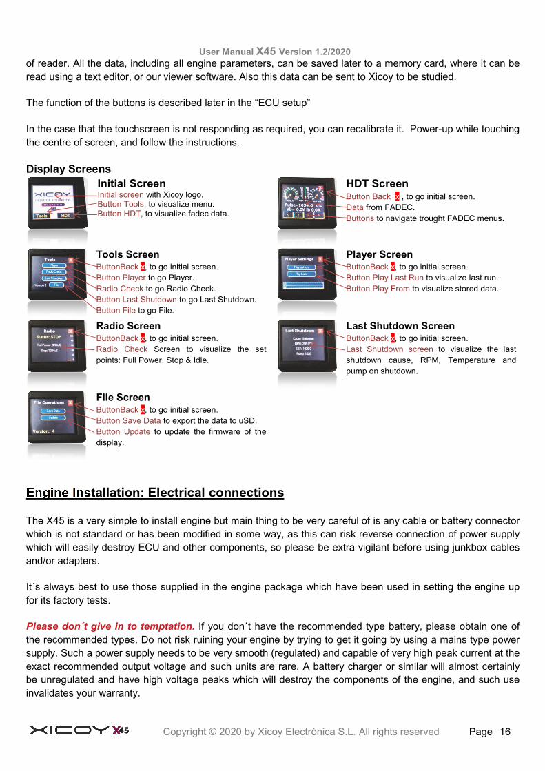
Display Screens Initial Screen Initial screen with Xicoy logo. Button Tools, to visualize menu. Button HDT, to visualize fadec data.
HDT Screen Button Back x , to go initial screen. Data from FADEC. Buttons to navigate trought FADEC menus.
Tools Screen ButtonBack x, to go initial screen. Button Player to go Player. Radio Check to go Radio Check. Button Last Shutdown to go Last Shutdown. Button File to go File.
Player Screen ButtonBack x, to go initial screen. Button Play Last Run to visualize last run. Button Play From to visualize stored data.
Radio Screen ButtonBack x, to go initial screen. Radio Check Screen to visualize the set points: Full Power, Stop & Idle.
Last Shutdown Screen ButtonBack x, to go initial screen. Last Shutdown screen to visualize the last shutdown cause, RPM, Temperature and pump on shutdown.
File Screen ButtonBack x, to go initial screen. Button Save Data to export the data to uSD. Button Update to update the firmware of the display.
Engine Installation: Electrical connections
The X45 is a very simple to install engine but main thing to be very careful of is any cable or battery connector which is not standard or has been modified in some way, as this can risk reverse connection of power supply which will easily destroy ECU and other components, so please be extra vigilant before using junkbox cables and/or adapters.
It´s always best to use those supplied in the engine package which have been used in setting the engine up for its factory tests.
Please don´t give in to temptation. If you don´t have the recommended type battery, please obtain one of the recommended types. Do not risk ruining your engine by trying to get it going by using a mains type power supply. Such a power supply needs to be very smooth (regulated) and capable of very high peak current at the exact recommended output voltage and such units are rare. A battery charger or similar will almost certainly be unregulated and have high voltage peaks which will destroy the components of the engine, and such use invalidates your warranty.

User Manual X45 Version 1.2/2020
Copyright © 2020 by Xicoy Electrònica S.L. All rights reserved Page 17
Just order yourself a good, high quality battery of the recommended type and use the wait for it to arrive by checking through your installation and these notes.
When it does arrive please double check the polarity of the connector supplied before plugging in.
A reverse polarity battery connection WILL destroy the ECU and engine components.
ECU setup
The ECU is contained on the engine. All the operating parameters relating to the starting and running of the engine are contained in its memory. All communications with the outside world occurs through the cable connected to the external Hub unit. The signal from the user radio receiver throttle channel is used to initiate and control all functions relating to engine operation.
Interaction with the ECU and modifying or adjusting of any parameter or setting is done via buttons on a display unit, also plugged into the Hub. The ECU battery should be plugged in as well as receiver, to access the display.
The ECU on the engine and all its components have been carefully programmed and tested together at the factory. They are then subject to rigorously testing together to ensure they all operate as expected so there is very little for the user to do to get the engine operational beyond the installation process and align the transmitter to the ECU
Once the engine is correctly installed and the components of the fuel system are fitted and connected up, the ECU can be aligned to the radio system. This is a simple procedure which should be done whenever your radio is programmed for a model, or the engine is new or returned from service or repair. Confirm you have connected the ECU signal input to the throttle channel on your receiver. Connect the display to the Hub if your system uses a separate display. Connect the ECU battery and note the display screen illuminates. To navigate through the menus the two left buttons move up and down the menus, the two right buttons increase and decrease the value set. There is no need to confirm any settings as changing a value automatically update it.
Remove all rates, mixes, and throttle travel settings in the transmitter.
User Manual X45 Version 1.2/2020
Copyright © 2020 by Xicoy Electrònica S.L. All rights reserved Page 18
Set the throttle maximum at 100%, minimum to -100% and adjust the failsafe to -125%. Before doing any adjustment on the ECU, check that your transmitter is sending the correct signal by checking the reading on the display.
Press the 2nd button from left once to show an information screen. Note at the top left there is a number showing the received radio signal shown as “Pulse = xxxxuS”. It should be between around 900 in Failsafe, around 1000-1050uS at STOP position, between 1100 and 1300uS at IDLE position and between 1800 and 2200uS at Full Power position. Exact readings are not important, but ensure that there are at least 100uS difference between failsafe and Stop, and another 100uS between Stop and Idle positions.
Ignore the % reading to the top right for the moment. Please note that these readings are measured directly from the signal received from your RC system, so you should readjust your transmitter if the values read are outside that the ones suggested.
On some Futaba transmitters, it has been found that the throttle channel the sense of movement may require reversing (servo reverse) and to repeat the transmitter alignment. The setting up assumes the use of a transmitter (TX) with manual trims.
If you use a TX with digital trims, is essential to use the switch in the TX programmed for the function "Throttle cut", or “engine cut” which normally has the effect of producing the “trim-down” function. Using a digital trim cause unstable idle, and delay in shutting off the engine in emergency.
Check your radio manual for this before you start. Avoid using the digital trim if at all possible.
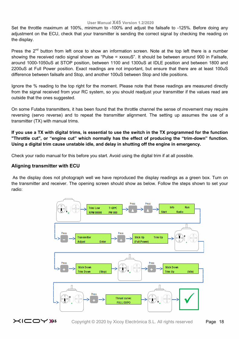
Aligning transmitter with ECU
As the display does not photograph well we have reproduced the display readings as a green box. Turn on the transmitter and receiver. The opening screen should show as below. Follow the steps shown to set your radio:
User Manual X45 Version 1.2/2020
Copyright © 2020 by Xicoy Electrònica S.L. All rights reserved Page 19
The correct adjustment of the throttle adjustment on the ECU can be verified in the second screen of the display as used before. The percentage of the throttle position should read 0% at the position of engine stop (trim and stick down), 100% with stick/trim full up and between 10% and 30% at idle.
This now completes your radio setup and should only need doing again if the radio settings are changed.
Failsafe, Never fly with the failsafe set to “hold”. It is strongly recommended that you setup your radio system with the correct failsafe settings. In some countries is mandatory that the engine stops in 2 seconds in the case of a failure of the radio link.
To program correctly the failsafe on your radio:
1) Adjust the travel of the throttle channel from -100% (stop position) to +100% (full power)
2) Adjust the ECU to your radio as described above.
3) Adjust the failsafe position of the throttle channel in your radio to -125%.
If all is correctly adjusted, the ECU will stop the engine immediately when receive the “STOP” signal (-100%), but if the signal received is Failsafe (-125%) the ECU will set Idle power during 2 seconds, and, if after these 2 seconds the Failsafe condition persists, will shut down the engine.
Once you have the radio programmed, check it by setting the throttle to any position, then switching off the transmitter; after two seconds the “failsafe” reading should be displayed.
Telemetry
The operation of the engine can be monitored remotely by a compatible RC transmitter or by a smartphone through Bluetooth.
To get the telemetry data displayed on the transmitter, Xicoy offers 3 different accessories, to be purchased separately. To connect to RC radios of brands Multiplex, Jeti, Futaba, Hott, Core and FrSky, it is needed the adapter “Tele 5” or newer. Older adapters for older ecus (Tele1 to Tele 4) are not compatible with the newest Xicoy engines.
To connect to Spektrum, you need the “Spek2” adapter. Old Spek adapter is not compatible.
You also can use the Xicoy Flight Computer (FC1) to connect to all these radios, old models of FC1 can be upgraded easily on the field.
To connect to an Android or Apple Smartphone, you need an Blue2 adapter. Same as other devices, older adapters used in other engines are not compatible with the newest high performance ecu used on the X45.
These devices are connected to the DATA port on the hub. Can be connected at same time as the colour display using an “Y” lead. This connection goes directly to the data bus on the engine, connecting a not compatible device would prevent the engine to run properly, or damage the ecu and other ancillary devices, so please DO NOT CONNECT anything to the Data port that has not been supplied by Xicoy.
Please check the user manual for these different devices to adjust your transmitter to receiver the data.
User Manual X45 Version 1.2/2020
Copyright © 2020 by Xicoy Electrònica S.L. All rights reserved Page 20
Preparing the engine for running
A suitable test stand should be made to hold the engine. A pair of sturdy timber rails securely fixed to a base board will suffice. Use screws to hold together, don´t rely on a nailed assembly. The engine can be secured to the rails using good quality woodscrews. Use at least 20mm/3/4” long to be sure the engine is properly secure.
A platform/table/workbench is required to clamp or fix the test stand onto. Make sure this can be easily transported outside and weight enough to ensure it cannot be blown over by the thrust of the engine. Set up the fuel tank, fuel pump, battery and display onto the baseboard, ideally secured. Nothing should be fixed downstream of the engine.
Select a clear area for running – keep clear of areas with loose leaves, sand or other debris that could be picked up or drawn towards the intake. Ensure the fuel tank is position well clear of the exhaust area and secured. You and your helper and any spectators should stand at the front of the engine, not to the side.
Important notes for kerostart engines: PLEASE READ
The kerostart system used on this engine is a reliable and well tested system that produces very smooth and trouble free starts. However, extra care and attention must be paid when starting a kerostart engine.
The main difference between gas and kerosene is that in the case of a failed ignition, the gas dissipates quickly in the air and won't stay inside the engine. Kerosene (or diesel) is liquid and if unburned, will pool inside the engine and stay there forever. The engine can hold a big quantity of kerosene inside. This kerosene will be ignited on next successful start-up and will be pushed to the exhaust as soon as the airflow inside the engine is sufficient, then it will be ignited in the exhaust, causing a hot start (in extreme cases a big fireball) that surely will not hurt the engine, but can destroy the model.
During startup
It is recommended on a new installation, to initiate a start and then abort the 1st start after about 5 seconds. This ensures fuel has reached all part of the engine. The start can then be repeated and allowed to complete. During the start-up listen to the engine sound to check for positive sound of ignition, check looking from the exhaust that the kero is burning, or check for an increase in exhaust temperature in the display. A small plume of white smoke from the exhaust means that the fuel is not burning. The fuel is pooling inside the engine. Abort immediately the start.
Double check that the engine is not flooded. An extra security measure is to place a manual valve between the pump inlet and tank, to prevent that during the process of filling the tanks or during storage, some fuel can arrive to the engine.
After a failed start, or whatever condition that could cause that fuel be collected inside the engine (ie accidental priming), ALWAYS empty the engine of fuel by tilting the engine nose down. Fuel will exit through intake. Do not tilt upwards; as due at the internal engine construction the fuel cannot exit out through the exhaust.
Another big difference between gas start and liquid start is that the kerosene can keep burning slowly for a long time inside the engine. This situation can happen during an aborted start, the start-up sequence is aborted by the user or automatically before the engine arrive to idle. This can cause that the kerosene inside the engine keep burning for long time, and could destroy the engine or the model.
IF START-UP SEQUENCE IS NOT COMPLETED, CHECK FOR FLAME INSIDE THE ENGINE.
User Manual X45 Version 1.2/2020
Copyright © 2020 by Xicoy Electrònica S.L. All rights reserved Page 21
If there is flame, then set the trim to idle position. The starter will be energized while the temperature is over 100ºC, cooling down the engine automatically. If temperature reading is low, you can get the starter running in manual mode by setting full throttle for over 3 seconds to engage the starter and blow out the flame. USE SHORT BURSTS OF STARTER. Using the starter for long time can overheat and destroy the starter motor. In the case that the start-up procedure has been aborted due to starter failure or the engine has jammed, then it will be necessary to apply the CO2 fire extinguisher. A white smoke plume from the engine is a good indication here; mean that there is no fire inside.
First engine runs Confirm your test stand is securely fixed to a bench or heavy table. Keep your ear defenders within easy reach and a CO2 fire extinguisher handy. VERY IMPORTANT ON KEROSTART ENGINES. Do not use a powder extinguisher, it will ruin the engine. Fill the fuel tank. Do not forget to filter the fuel, and to mix the oil. Confirm all batteries are freshly charged and connected up. Check there is a temperature reading on the display. Ensure the running area is clear of onlookers – especially the prohibited zone of a 10 metre radius 180° arc from engine centre around the rear Verify that the fuel tube is full of fuel and purged of all air, if not; carry out the fuel system prime sequence as described here. BUT do not prime fuel into the engine.
Priming the fuel system: Fuel system needs purging of all air after initial installation. Take extra care when priming the line, ensure fuel is primed only up 2cm before the engine; fuel inside engine will cause excessive flaming during start sequence. Priming is achieved by a menu on the display Set the trim to low and go to “Info” menu and then travel to “Pump test”. Click on “on” /”off” to start/stop the pump manually. Please observe fuel line to engine very carefully and push the off button to stop as soon as fuel reaches close to the engine. Best too short than risk flood the engine.
IMPORTANT: The prime procedure should be done only to fill the fuel tube and filter in the case of a first installation or in case of disassembling of the tubes. It does not need repeating. Pushing fuel directly into the engine will cause an uncontrolled fire at next start-up.
Starting the engine
Set the throttle stick down and the trim up (“Idle”). Confirm that the screen shows "Ready" ie Ready to start! In the case that the exhaust temperature is over 100º, the ECU will power the starter to cool down the engine. Wait until the cooling sequence finish.
Move the stick to full throttle and immediately back to idle again within 2 seconds. The ECU will begin the start-up sequence as described below:
First the internal glow plug will be energized. Soon after, the starter will be powered up to have the rotor turning at slow speed (3000- 5000 RPM).
Once the rotor is at correct speed, the fuel pump and solenoid valves will be energized. A few seconds later (depending if the fuel is already at the engine or not) the fuel will ignite and the exhaust temperature will begin to increase. The rpm and pump power will increase automatically. During this phase the display will display “IGNITION”.
When the ignition is detected, the display will change to “SwitchOver”, during this phase fuel is also routed to main injectors and speed of the rotor will be progressively increased to about 8,000RPM.
User Manual X45 Version 1.2/2020
Copyright © 2020 by Xicoy Electrònica S.L. All rights reserved Page 22
Once this phase is finished, the RPM rises to 10,000RPM and the reading will be “FUEL RAMP”. In this phase the ignition system is switched off.
The fuel flow and starter power will be increased automatically to increase the RPM quickly up to idle at 60,000RPM. Before arriving to idle the ECU will automatically disconnect power to the starter. When the rotor speed reaches idle, the screen will change to “Run IDLE” and the engine speed is adjusted to the idle RPM.
The engine is running!
Control of engine power/rpm is now handed back to the transmitter and controlled by the position of the throttle stick. Initially Increase/decrease the throttle slowly, verifying that the engine accelerates/decelerates following the throttle command. Take special care around the engine intake; keep your hands at a safe distance along with any objects as they can be easily ingested.
Engine shut down procedure
To shut down the engine lower the trim and the stick. It is recommendable that before shutting down the engine to restrain the model and then raise the throttle stick to approximately 25%, allowing temperatures to stabilize for around 5 seconds before carrying out the shutdown procedure. After the shutdown the ECU will keep the starting motor running to cool the engine under 100ºc. A special feature on this system is that the power of the receiver can be switched off before the cooling procedure is complete. The ECU will shut down itself when the procedure is complete.
WHAT TO DO IN THE CASE OF AN EMERGENCY
During the start sequence the ECU will be in charge of everything, controlling temperature and RPM. The only thing the user can do is to abort the sequence by lowering the trim in the case that something abnormal (excessive flames in the exhaust, etc).
If a problem is detected, first: Move the trim to the low position to abort the sequence. If there is a fire in the engine and the problem is because the starter has failed or the engine is seized (not turning), IMMEDIATELY APPLY THE FIRE EXTINGUISHER through the intake side of the engine, never through the exhaust. If there is a fire, but the rotor remains free to spin and the starter is OK, raise the trim and stick to the full power position for 3 seconds, this will connect the starter manually to ventilate the engine and extinguish the fire. The throttle channel acts as a starter switch.
Adjusting the engine maximum power
The engine comes from factory adjusted for its maximum thrust. But it is possible to reduce the maximum power if necessary. To do so, go to RUN menu and scroll the menus up to “Max RPM”. Using the + and – buttons, you can change the rotor speed at full throttle. Beside the full power RPM, the equivalent thrust in Newton and in Lb. Please note that these figures are calculated based on an ambient temperature of 15ºC at sea level. Hotter ambient/higher altitude will reduce the power output.
Autorestart function
X45 engines include the AUTORESTART function. This function can quickly restart an engine automatically, but it should be understood that such a system may cause damage to people and property if triggered
User Manual X45 Version 1.2/2020
Copyright © 2020 by Xicoy Electrònica S.L. All rights reserved Page 23
inappropriately. By default this function is disabled in the ECU, the user should expressly enable it. By enabling this function, the user agrees that they have understood the working principles and understands its limitations.
Restart options and how to enable them:
Within the “Radio” menu, a selection defines the restart operation. The ECU offers 3 choices:
Standard operation (off): After the shutdown the ECU should be reset (power cycled off then on) to enable another start-up cycle. Engines are supplied in this mode from factory.
Manual restart: User can normally shutdown the ECU through the transmitter (by lowering the stick and trim). The ECU will execute the normal shutdown and post run cooling cycle. Once the cooling is finished (temperature below 100ºC), the ECU will return to power-up state allowing the engine to be restarted through the normal procedure (Trim-up, cycle stick). The time to shut down and later start is exactly the same as standard operation. This mode is useful for gliders, where the engine is used to climb to height, shutdown, soaring, restart, climb, etc. This mode does not pose any safety hazard besides the fact that the engine can be started inadvertently if the start procedure is executed in the transmitter after the flight.
Auto-restart: In particular case of a fuel bubble that momentarily stops the combustion, the ECU will detect this condition by monitoring the rpm, temperature and pump power, and then the ECU triggers the auto-restart sequence. This sequence is done with the engine hot, so the power is restored quickly. This restarting function can help save the plane in few limited circumstances.
But it can also greatly increase the risk of fire, so before to enable this function, please read and understand the following:
What the auto-restart function does:
It automatically tries to restart the engine quickly and restore the power setting that is being asked by the transmitter. To trigger this function, the ECU checks:
The radio signal is valid, no failsafe condition. The readings of the RPM are consistent with a flameout condition (the speed of the RPM coasting down is between pre-set limits). The readings of the exhaust temperature are consistent with a flameout condition. The battery voltage is good.
No other faults detected.
Once the ECU is satisfied that the shutdown/flameout was most likely caused by an interruption of combustion, usually caused by an air bubble, the ECU triggers the quick restart function, where the ignitor is energized to full voltage and the pump is started at a power dependent of the current engine status (RPM and EGT). Once the ECU detects that the combustion has resumed, the starter power is set to full power to reach the idle rpm as quickly as possible, and the pump power is increased accordingly to the real RPM increase, allowing for delays caused by bubbles arriving to the engine. If after 10 seconds of restart the ECU doesn’t detect a stable combustion, the procedure is aborted and the normal cooldown initiated.
What the Autorestart function will not do:
It will not restart the engine if the shutdown was caused by any fault other than a typical flame out caused by air in the fuel system. It will not monitor and confirm flight conditions are optimum for a restart. Leaving the restart to progress is the pilot responsibility and decision, depending on each particular case.
User Manual X45 Version 1.2/2020
Copyright © 2020 by Xicoy Electrònica S.L. All rights reserved Page 24
When should Autorestart function be enabled?
Auto-restart is fast but still takes an average time of 10s to establish restored level of pre-shutdown power. It is highly recommended that Auto-restart only be used on airframes capable of sustaining enough flight for the re-start to be completed. Some aircraft examples include: lightly loaded planes, gliders, or multi engine planes.
It is highly advised that a shutdown simulation be done before selecting Auto-restart option in the ECU RADIO menu. Do it during a normal flight at a high altitude, then throttle down to idle then begin a 10sec count down. From this try to gauge if the aircraft can maintain controlled flight during this time at idle setting.
If your plane cannot maintain flight for a minimum of 10sec without engine power, do not enable the Auto restart function.
“I’m flying my plane and the engine has shutdown with restart enabled, what should I do”:
Think that the chances of that the engine restart are slim. You don’t know why it has shut down, so likely it will not restart, DO NOT RELY on it. Fly your plane. Leave the throttle at mid setting and fly your plane keeping airspeed in aft for a dead stick landing. In case you see the plane begins to stall or an uncontrolled landing is most likely, IMMEDIATELY set the trim and stick to STOP position to abort the restart function. A crash with the engine running normally ends with a fireball; a crash with the engine off is not likely to catch fire.
Do not use the “digital trims” to shut down the engine, use a dedicated switch to be operated quickly. If the engine restart is initiated while on approach, evaluate if the speed/position of the plane is still good for a safe landing, if so, land immediately, you don’t know why the engine stopped and may stop again during a “go around” but this time the aircraft may not be in an as favourable position. If the position/speed of the plane is not convenient, use the engine power to go around and plan for a normal landing, BUT land as soon as possible. Once the plane is on the ground, even in normal landing or crash landing, set the transmitter in the STOP position. The engine could restart and go to full power on its own; the ECU does not know when the plane is on the ground. “Can I use the restart function many times”? NO!
Restart function is an emergency procedure and places a high stress on the engine ancillary components. The starter and ignitor are fed with extra power that is not used in normal startups, this places considerable more wear on them, also the engine is subjected to abrupt temperature changes that could shorten its life.
Restart function is not the replacement of a poor fuel system. It can save a plane in particular circumstances, but it can do much more harm than good. A belly landing or landing gear damage due to a flameout induced heavy landing is more favourable than a similar landing arrival with the engine in start phase that can possibly cause a fire and result in total destruction of the model and or property.
Please consider carefully before enabling the auto-restart feature.
Never test the auto-restart function by closing the fuel line after the pump, this could cause a overload in the pump that can damage it.
Disclaimer There are no circumstances Xicoy Electronica SL or any of its Service Agents and employees will accept or be held responsible for any losses or damages the Auto Restart feature causes should the owner operator choose to enable this function.
User Manual X45 Version 1.2/2020
Copyright © 2020 by Xicoy Electrònica S.L. All rights reserved Page 25
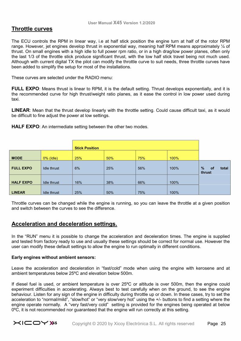
Throttle curves
The ECU controls the RPM in linear way, i.e at half stick position the engine turn at half of the rotor RPM range. However, jet engines develop thrust in exponential way, meaning half RPM means approximately ¼ of thrust. On small engines with a high idle to full power rpm ratio, or in a high drag/low power planes, often only the last 1/3 of the throttle stick produce significant thrust, with the low half stick travel being not much used. Although with current digital TX the pilot can modify the throttle curve to suit needs, three throttle curves have been added to simplify the setup for most of the installations.
These curves are selected under the RADIO menu:
FULL EXPO: Means thrust is linear to RPM, it is the default setting. Thrust develops exponentially, and it is the recommended curve for high thrust/weight ratio planes, as it ease the control in low power used during taxi.
LINEAR: Mean that the thrust develop linearly with the throttle setting. Could cause difficult taxi, as it would be difficult to fine adjust the power at low settings.
HALF EXPO: An intermediate setting between the other two modes.
Stick Position
MODE 0% (Idle) 25% 50% 75% 100%
FULL EXPO Idle thrust 6% 25% 56% 100% % of total thrust
HALF EXPO Idle thrust 16% 38% 66% 100%
LINEAR Idle thrust 25% 50% 75% 100%
Throttle curves can be changed while the engine is running, so you can leave the throttle at a given position and switch between the curves to see the difference.
Acceleration and deceleration settings.
In the “RUN” menu it is possible to change the acceleration and deceleration times. The engine is supplied and tested from factory ready to use and usually these settings should be correct for normal use. However the user can modify these default settings to allow the engine to run optimally in different conditions.
Early engines without ambient sensors:
Leave the acceleration and deceleration in “fast/cold” mode when using the engine with kerosene and at ambient temperatures below 25ºC and elevation below 500m.
If diesel fuel is used, or ambient temperature is over 25ºC or altitude is over 500m, then the engine could experiment difficulties in accelerating. Always best to test carefully when on the ground, to see the engine behaviour. Listen for any sign of the engine in difficulty during throttle up or down. In these cases, try to set the acceleration to “normal/mild”, “slow/hot” or “very slow/very hot” using the +/- buttons to find a setting where the engine operate normally. A “very fast/very cold” setting is provided for the engines being operated at below 0ºC, it is not recommended nor guaranteed that the engine will run correctly at this setting.
User Manual X45 Version 1.2/2020
Copyright © 2020 by Xicoy Electrònica S.L. All rights reserved Page 26
It is much better to have an engine respond slower to throttle changes than one that just stop when asked to accelerate faster than possible in difficult ambient conditions!
Later engines with ambient sensors:
On these engines, there is an extra acceleration setting called AUTO. In AUTO mode, the ecu adjusts itself for optimum running at the current ambient conditions, and, in extreme cases, it raises the idle speed accordingly. Leave always your ecu in AUTO for optimum, trouble free performance.
Exhaust tubes
The size and placement of the exhaust tube is not an exact science. The optimum tube diameter and the gap between the engine exhaust and the tube intake is largely dependent of the airframe. A slow airframe with big intakes will benefit from larger exhaust diameter and larger gap to get the maximum static thrust possible. A fast airframe, with small intakes, bypass installation, will benefit of smaller exhaust diameter and smaller gap to get the maximum efflux speed.
As a general guideline, use an exhaust tube of a diameter equal or larger than 45mm (1.8”) diameter, with a gap between the engine exhaust and beginning of exhaust tube (excluding the bell mouth) of 25mm (1”).
Later you can experiment moving the engine 5mm (0.2”) forward or aft to see if performance is better. Too larger gap will cause hot gases to recirculate to the engine intake, decreasing performance and worsening the acceleration or causing the engine to stop. Too short gap will cause extra pipe noise and depression inside the pipe, in extreme cases the exhaust tube can collapse due the low pressure inside (venture effect).
Use in gliders and in 3D planes
If you plan to use your engine in a glider, please consider to de-rate your engine. The typical use that is running at full power continuously for the entire flight in airframes that easily weight 4 times the engine thrust is very hard for the engine, as the internal elements like combustion chamber are subjected to maximum temperature and stress all the time, reducing the time between overhauls. We would recommend using the engine at 80% of its maximum power in these conditions, or using the 100% for take-off, but later reducing to 80% during continuous climb.
We don’t recommend using our engines in 3D planes doing fast acrobatics. The gyroscopic forces that a turbine rotor turning at +220.000RPM apply to the bearings doing a loop in less than 1s are extremely high and can destroy the bearings or cause the compressor or turbine wheels to rub to the engine case. Warranty will not cover this kind of damage.
List of ECU message codes
Here is a list of possible messages shown on the data terminal screen and their meaning:
TrimLow: Indicates that the signal received from the transmitter corresponds to the lowered trim, that is to say, engine OFF
Ready: Indicates that the engine is ready for starting, and that the transmitter signal corresponds to IDLE.
StickLo!: This indicates that the throttle stick is in a position above IDLE, the engine will not start with the stick in this position.
Glow Test: Verification of glow plug
StartOn: Test of the starter and rpm sensor

User Manual X45 Version 1.2/2020
Copyright © 2020 by Xicoy Electrònica S.L. All rights reserved Page 27
Ignition: Ignition phase.
SwitchOver: Phase of heating of the combustion chamber after detecting the ignition.
FuelRamp: Phase of acceleration until idle speed.
Run Idle: Engine working correctly, pilot have full control of engine power, command received from transmitter is IDLE.
Running: Engine working correctly, pilot have full control of engine power, command received is an intermediate setting between Idle and Full Power.
Run-Max: Engine working correctly, pilot have full control of engine power, command received is Full Power
CalPump: Pump is being calibrated; it is an informative message, nothing to worry about.
Stop: Engine off.
Cooling: Starter is operating to cool the engine.
GlowBad: Defective or disconnected glow plug.
StartBad: Defective starter, insufficient RPM reached during start, RPM sensor damaged, too thick oil used on previous run, no cooling sequence done in previous run.
Low RPM: Engine had been shut down because the speed has fallen below the minimum. Usually lack of fuel (or an air bubble(s) has passed through the pump)
HighTemp: Excessive temperature
Battery!: battery voltage out of limits.
Pump Overload: There is a restriction in the fuel path from the pump to the engine, or in the engine itself.
No Data: Means that the data terminal is not receiving any data from the engine. Usual causes are: Ecu battery disconnected, data terminal connected in wrong port, throttle lead connected in wrong port, pump lead connected revesed.
Diagnoses
During engine operation the ECU measures and stores all the engine operating parameters recorded during the last the 51 minutes of operation. These measures can be downloaded later to a PC to study the behaviour of the engine in flight and to diagnose any possible problems. Also, after each cycle of operation, the ECU stores the last cause of shut down and the values of RPM, temperature and pump power.
In order to access these measures, it is necessary to shut down and power-up the ECU. Set the trim down (trimLow) and push the left button on the display. The ECU will show the cause of last shutdown and the parameters value at the moment of shut down.
Diagnosis messages:
1. UserOff: The engine has been shut down because it has received the shutdown command from the transmitter.
2. FailSafe: The engine has been shut down because of loss of the control signal from the transmitter. After 0,5s of detecting a loss or invalid RC signal, the ECU sets engine power to idle, and if after another 1,5seconds a valid signal is still not received the engine is shut down.
3. LowRPM: The engine has been shut down because the RPM has dropped below a minimum. Cause could be lack of fuel, air bubbles, problem with the batteries, or defective RPM sensor.

User Manual X45 Version 1.2/2020
Copyright © 2020 by Xicoy Electrònica S.L. All rights reserved Page 28
4. RCPwFail: Lack of power from the radio receiver.
For further Information and updates on this engine and available Xicoy Electronica help and support:
Check our new dedicated turbine webpage at www.Xicoyturbines.com