XFi: Cross-technology IoT Data Collection via Commodity WiFi
11
XFi: Cross-technology IoT Data Collection via Commodity WiFi Ruofeng Liu * , Zhimeng Yin * , Wenchao Jiang † , Tian He * * University of Minnesota † Singapore University of Technology and Design [email protected] Abstract—Wireless technologies are increasingly diversified to serve various Internet-of-things applications. Yet, our mobile devices (e.g., smartphones) are manufactured with limited types of wireless radio, making it challenging to access the data in the heterogeneous IoT devices. To address this fundamental problem, this work proposes XFi, which enables mobile devices to use commodity WiFi radio to directly and simultaneously collect data from diverse heterogeneous IoT devices. Our critical insight is that when an IoT frame collides with an ongoing WiFi transmis- sion, its IoT data is captured by WiFi receiver and retained even after the demodulation procedures in WiFi hardware. Motivated by this observation, XFi proposes a general approach to obtain IoT data by analyzing the decoded WiFi payload. The method is fully compatible with existing commodity WiFi hardware and generally applicable to various IoT protocols. We implement XFi on commodity devices (e.g., RTL8812au, CC2650, and SX1280). Our comprehensive evaluation demonstrates that XFi can collect data from 8 IoT devices in parallel with over 97% accuracy, offering reliable cross-technology data collection. Index Terms—WiFi, ZigBee, LoRa, Internet-of-Things I. I NTRODUCTION Internet of things (IoT) are rapidly expanding to every aspect of our daily life with the unprecedented proliferation of heterogeneous wireless devices (e.g., ZigBee sensors, LoRa smart meters, Bluetooth smart wearable, and wireless baby monitors). Naturally, people desire to use their mobile devices (e.g., smartphones) to interact with the diverse IoT devices, manage IoT data, and conduct data fusion operations. How- ever, the increasing diversity of wireless technologies adopted by IoT devices brings about a unique challenge: due to the constraints in the size and complexity, mobile devices are manufactured with limited types of wireless radios such as WiFi and Bluetooth, which inhibits them from directly collect data from heterogeneous IoT devices (e.g., ZigBee and LoRa). To alleviate this issue, we study the possibility to extend the pervasively available radio in mobile devices, i.e., WiFi, to support heterogeneous IoT techniques in the overlapping ISM spectrum. By doing this, we envision that with a moderate software upgrade, mobile devices can collect data from various types of heterogeneous IoT devices directly, which paves the way for a lot of novel IoT applications. However, it is technically challenging to enable data ex- change between WiFi and heterogeneous IoT radio due to their distinct physical layers. Recent advances in cross-technology communication [9], [30], [31] propose signal emulation, i.e., manipulating high-speed WiFi radio to emulate low-speed Zig- Bee signal, which allows WiFi to deliver messages to ZigBee. Nevertheless, this series of techniques are not applicable to the communication from low-speed IoT radios back to WiFi because IoT radios generally have very limited capabilities - it is impossible for a ZigBee radio with a 2 MHz bandwidth to produce a 20 MHz WiFi signal. To address this problem, there are a few previous attempts [18], [39]. Yet, they are fundamentally limited in compatibility and generality. Specifically, they need to modify the WiFi demodulation procedure for customized decoding of raw IoT signal, making them incompatible with billions of existing commodity WiFi radio in the smartphone. In addition, they are inherently restricted to only support ZigBee without serving other IoT techniques that are being increasingly diversified. This paper presents XFi - the first design that achieves data collection from diverse heterogeneous IoT devices using commodity WiFi radio with only a software upgrade. The basic idea is signal hitchhiking - when a smartphone is receiving a WiFi packet from an AP, IoT devices transmit simultaneously, leading to intentional collisions with the WiFi packet in the air. In this way, low-speed IoT data hitchhikes on the high-speed WiFi packet and enters the WiFi radio of the smartphone. The most critical question XFi needs to address in this paper is how to obtain the IoT data hitchhiking on the received WiFi packet. With our goal of serving diverse IoT techniques with distinct physical layers in minds, XFi proposes a general approach: reconstruct and decode, i.e., 1) reconstruct the I/Q waveform of hitchhiking IoT data and then 2) decode the reconstructed IoT waveform. Although the idea sounds straightforward, it is extremely challenging to accomplish in a commodity WiFi device with only a software upgrade. In particular, commodity WiFi hardware does not expose raw I/Q data to the software - It only returns the decoded WiFi payload after WiFi demodulation. To reliably retrieve IoT data from the decoded payload, XFi has to tackle several critical challenges imposed by WiFi demodulation procedures. • Waveform Reconstruction: Commodity WiFi receiver ap- plies forward error correction (FEC) algorithm to correct errors incurred by wireless interference. Consequently, the hitchhiking IoT signal could be considered by FEC as interference and eliminated amid error correction, rendering it challenging to reconstruct IoT waveform from the decoded WiFi payload. Counter-intuitively, we 978-1-7281-6992-7/20/$31.00 ©2020 IEEE
Transcript of XFi: Cross-technology IoT Data Collection via Commodity WiFi
XFi: Cross-technology IoT Data Collection viaCommodity WiFi
Ruofeng Liu∗, Zhimeng Yin∗, Wenchao Jiang†, Tian He∗∗University of Minnesota
†Singapore University of Technology and [email protected]
Abstract—Wireless technologies are increasingly diversified toserve various Internet-of-things applications. Yet, our mobiledevices (e.g., smartphones) are manufactured with limited typesof wireless radio, making it challenging to access the data in theheterogeneous IoT devices. To address this fundamental problem,this work proposes XFi, which enables mobile devices to usecommodity WiFi radio to directly and simultaneously collect datafrom diverse heterogeneous IoT devices. Our critical insight isthat when an IoT frame collides with an ongoing WiFi transmis-sion, its IoT data is captured by WiFi receiver and retained evenafter the demodulation procedures in WiFi hardware. Motivatedby this observation, XFi proposes a general approach to obtainIoT data by analyzing the decoded WiFi payload. The methodis fully compatible with existing commodity WiFi hardware andgenerally applicable to various IoT protocols. We implement XFion commodity devices (e.g., RTL8812au, CC2650, and SX1280).Our comprehensive evaluation demonstrates that XFi can collectdata from 8 IoT devices in parallel with over 97% accuracy,offering reliable cross-technology data collection.
Index Terms—WiFi, ZigBee, LoRa, Internet-of-Things
I. INTRODUCTION
Internet of things (IoT) are rapidly expanding to everyaspect of our daily life with the unprecedented proliferationof heterogeneous wireless devices (e.g., ZigBee sensors, LoRasmart meters, Bluetooth smart wearable, and wireless babymonitors). Naturally, people desire to use their mobile devices(e.g., smartphones) to interact with the diverse IoT devices,manage IoT data, and conduct data fusion operations. How-ever, the increasing diversity of wireless technologies adoptedby IoT devices brings about a unique challenge: due to theconstraints in the size and complexity, mobile devices aremanufactured with limited types of wireless radios such asWiFi and Bluetooth, which inhibits them from directly collectdata from heterogeneous IoT devices (e.g., ZigBee and LoRa).
To alleviate this issue, we study the possibility to extendthe pervasively available radio in mobile devices, i.e., WiFi,to support heterogeneous IoT techniques in the overlappingISM spectrum. By doing this, we envision that with a moderatesoftware upgrade, mobile devices can collect data from varioustypes of heterogeneous IoT devices directly, which paves theway for a lot of novel IoT applications.
However, it is technically challenging to enable data ex-change between WiFi and heterogeneous IoT radio due to theirdistinct physical layers. Recent advances in cross-technologycommunication [9], [30], [31] propose signal emulation, i.e.,
manipulating high-speed WiFi radio to emulate low-speed Zig-Bee signal, which allows WiFi to deliver messages to ZigBee.Nevertheless, this series of techniques are not applicable tothe communication from low-speed IoT radios back to WiFibecause IoT radios generally have very limited capabilities -it is impossible for a ZigBee radio with a 2 MHz bandwidthto produce a 20 MHz WiFi signal.
To address this problem, there are a few previous attempts[18], [39]. Yet, they are fundamentally limited in compatibilityand generality. Specifically, they need to modify the WiFidemodulation procedure for customized decoding of raw IoTsignal, making them incompatible with billions of existingcommodity WiFi radio in the smartphone. In addition, they areinherently restricted to only support ZigBee without servingother IoT techniques that are being increasingly diversified.
This paper presents XFi - the first design that achievesdata collection from diverse heterogeneous IoT devices usingcommodity WiFi radio with only a software upgrade. The basicidea is signal hitchhiking - when a smartphone is receiving aWiFi packet from an AP, IoT devices transmit simultaneously,leading to intentional collisions with the WiFi packet in the air.In this way, low-speed IoT data hitchhikes on the high-speedWiFi packet and enters the WiFi radio of the smartphone.
The most critical question XFi needs to address in this paperis how to obtain the IoT data hitchhiking on the receivedWiFi packet. With our goal of serving diverse IoT techniqueswith distinct physical layers in minds, XFi proposes a generalapproach: reconstruct and decode, i.e., 1) reconstruct theI/Q waveform of hitchhiking IoT data and then 2) decodethe reconstructed IoT waveform. Although the idea soundsstraightforward, it is extremely challenging to accomplish ina commodity WiFi device with only a software upgrade. Inparticular, commodity WiFi hardware does not expose raw I/Qdata to the software - It only returns the decoded WiFi payloadafter WiFi demodulation. To reliably retrieve IoT data from thedecoded payload, XFi has to tackle several critical challengesimposed by WiFi demodulation procedures.• Waveform Reconstruction: Commodity WiFi receiver ap-
plies forward error correction (FEC) algorithm to correcterrors incurred by wireless interference. Consequently,the hitchhiking IoT signal could be considered by FECas interference and eliminated amid error correction,rendering it challenging to reconstruct IoT waveformfrom the decoded WiFi payload. Counter-intuitively, we978-1-7281-6992-7/20/$31.00 ©2020 IEEE

observe that IoT waveform is retained even after errorcorrection, so that XFi manages to reconstruct a largeportion of IoT waveform from the decoded payload.
• Robust Decoding: Commodity WiFi receiver discards in-formationless segments of WiFi signal (e.g., guard inter-vals between WiFi symbols). Thus, IoT signal hitchhikingon these discarded segments cannot be recreated in thereconstructed waveform. To cope with the challenge andreliably obtain IoT data, we enhance IoT decoders, whichprovides them robustness against discarded waveform.
Importantly, our proposed methods are generally applicableto various types of IoT techniques, which is essential for ourmotivation for supporting diversified IoT devices. We demon-strate the applicability to two representative IoT techniquesusing highly distinct physical layers: ZigBee and LoRa whilethey can be extended to other techniques.
In summary, our intellectual contributions are as follows:• XFi is the first work that enables data collection from
diverse IoT techniques with a commodity WiFi radio,without compromising WiFi demodulation.
• Our design simultaneously features generality to variousIoT techniques and compatibility with commodity WiFihardware. To achieve this, XFi obtains IoT data onlyusing decoded payload while tackling critical challenges,e.g., waveform construction and robust decoding.
• We implement XFi on COTS WiFi devices (e.g.,RTL8812au) and evaluate XFi across various scenarios.The results demonstrate that XFi can concurrently receive2 streams of ZigBee or 8 streams of LoRa with 97%accuracy while reaching a throughput of 1.8 Mbps.
II. MOTIVATIONThis section presents the motivation of cross-technology IoT
data collection using commodity WiFi radio in a smartphone.Deficiency of IoT Support in Smartphone: Internet of
Things (IoT) has been widely deployed, where a large numberof heterogeneous IoT devices are generating more than 500zettabytes IoT data per year [13]. A natural way for peo-ple to interact with these ubiquitous IoT devices is throughtheir mobile devices (e.g., smartphones), which brings severalunique benefits. For example, a smartphone can provide afriendly user interface for visualizing and managing IoT data,while the powerful computing capability of the smartphonealso offers an ideal platform for analyzing heterogeneous IoTdata through sensor fusion and machine learning operations.
The challenge, however, is that wireless techniques adoptedin IoT devices are increasingly diversified while our mobiledevice is constrained to provide limited options of wirelesstechniques. For instance, environmental sensors are commonlyequipped with ZigBee, while smart meters could adopt LoRa.There are also a large number of IoT devices (e.g., healthwearable and baby monitors [34]) that use proprietary wirelessprotocols. In contrast, restricted by the size and complexity,a smartphone is only equipped with radios such as WiFi,while cramming additional IoT interfaces (e.g., ZigBee) intosmartphones [14] has been proved commercially inviable.
Conventionally, a smartphone has to indirectly access thedata in heterogeneous IoT devices via extra IoT gateways[3]. However, the dedicated gateway incurs additional hard-ware cost, deployment complexity, and administration burden,which prevents it from being ubiquitously deployed. In addi-tion, an IoT gateway with a specific wireless radio cannotserve other emerging IoT techniques. As a result, there isan emergent need for a low-cost and general method for theheterogeneous IoT data collection on mobile devices.
Cross-technology Data Collection via Commodity WiFi:We propose to directly collect data from heterogeneous IoTdevices with commodity WiFi radio available in every smart-phone. With a moderate software upgrade, smartphones canaccess diversified IoT devices without extra gateways.
Although direct communications from heterogeneous IoTradio to WiFi have been studied in recent works [18], [39],they commonly work on physical layers requiring a redesignof WiFi decoder. Therefore, they are incompatible with com-modity WiFi hardware in mobile devices. Furthermore, theirdesigns are tightly coupled with unique features of ZigBeesignal, which cannot be generalized to other types of IoTtechniques that are increasingly diversified.
In XFi, we simultaneously address the challenges in bothcompatibility and generality, enabling mobile devices to obtainIoT data of various heterogeneous techniques using only thedecoded WiFi payload that is accessible from WiFi software.
Fig. 1: (a) XFi Enables a WiFi Smartphone to Collect Datafrom Heterogeneous IoT Devices. (b) XFi Analyzes the De-coded WiFi Payload to Obtain ZigBee or LoRa Data.
III. XFI IN A NUTSHELL
Overview. XFi enables a commodity WiFi radio in mobiledevices to collect data from diversified narrowband IoT de-vices (e.g., ZigBee and LoRa1) with only a software upgrade.The high-level idea is signal hitchhiking demonstrated inFig.1(a): a mobile device downloads a standard WiFi datapacket from the associated WiFi AP. When the WiFi packet isbeing delivered by AP, IoT devices send data in the overlappedspectrum such that low-speed IoT data can hitchhike on the
1Note that while LoRa initially operates on the sub-GHz band, 2.4GHzLoRa transceivers (e.g., SX1280/SX1281) have been deployed since 2017.

high-speed WiFi packet in the air and enter the WiFi radioof the mobile device. In the rest of paper, we will refer toZigBee or LoRa radios as “IoT devices” and ZigBee or LoRadata frames as “IoT frames”.
Applicable scenarios. XFi is applicable in a wide rangeof scenarios since WiFi APs have been ubiquitously deployedfor Internet service. For example, over 79% US householdsget WiFi at home [6] while there are 432 million publicAPs worldwide [21]. Additionally, XFi is also possible tobe applied in mobile scenarios without WiFi APs. It is anincreasingly common situation that people carry more thanone mobile device. For instance, 60 million US people areusing smartwatches in addition to smartphones [15], whichcan serve as WiFi transmitters with only a software upgrade.
System architecture. The critical component of the systemis XFi software installed in mobile devices. As depicted inFig.1(b), it is able to obtain the hitchhiking IoT data withoutaccessing raw I/Q signal. Specifically, XFi software only usesthe decoded WiFi payload returned by commodity WiFi hard-ware as the input. To retrieve IoT data, it first reconstructs IoTwaveform by analyzing the decoded WiFi payload (Section§V) and then reliably decodes the reconstructed IoT waveformwith our enhanced IoT decoders (Section §VI).
XFi has three unique features:• Compatibility: XFi retrieves heterogeneous IoT data
only via the decoded payload available in WiFi software.Therefore, it is fully compatible with commodity WiFidevices and does not require any hardware modification.
• Generality: XFi manages to reconstruct raw RF wave-form of hitchhiking IoT data regardless of the wirelesstechnique it uses. This capability makes XFi generallyapplicable to various IoT protocols that coexist with WiFion ISM band. We demonstrate the generality with twopopular techniques (i.e., ZigBee and LoRa) with highlydifferent physical layers.
• Efficiency: XFi allows the wide-band WiFi receiver toconcurrently receive and decode multiple heterogeneousnarrowband IoT transmissions, significantly improvingthe network efficiency of densely-deployed IoT devices.Taking Fig.1(a) for example, XFi is able to simultane-ously decode the transmissions from two ZigBee devicesand four LoRa devices allocated at different channels.
IV. BACKGROUND AND CHALLENGES
This section introduces the background of commodity WiFireceiver and then analyzes the challenges of obtaining IoT dataunder the constraints of WiFi demodulation procedures.
Premeable
Detection
CP
RemovalFFT
QAM
Demapping
Channel
Decoding
t[n] t’[n] f[n]20MHz Signal
Coded BitsDecoded Bits
(i) (ii) (iii)
(v) (vi)
Fig. 2: Demodulation Procedures in WiFi Receiver.
A. Background
In Fig. 2, we illustrate how the WiFi receiver works. (i)Preamble detection searches the predefined training signal,i.e., WiFi preamble in the received 20 MHz signal. If thepreamble is detected, WiFi receiver conducts the followingOFDM demodulation procedures. Otherwise, the signal isrejected. (ii) For a signal t[n] that passes preamble detection,the cyclic prefix (CP), i.e., the 0.8us at the beginning ofeach 4us WiFi symbol is removed because it is an “in-formationless” guarding interval between WiFi symbols foreliminating the inter-symbol interference. (iii) The survivingtime-domain waveform t′[n] is transformed into the frequencydomain by Fast Fourier Transform (FFT). Each WiFi symbolis transformed into 64 frequency components that correspondto 64 WiFi subcarriers over 20 MHz WiFi spectrum. (v) TheQAM demapping discretizes the continuous-value frequencycomponents into bits. Then bits on all the subcarriers areserialized to a sequence of coded bits (or a codeword). (vi) Thechannel decoder corrects errors in coded bits using forwarderror correction (FEC) algorithm and produces decoded bitsthat are available in WiFi software. Note The corrupteddecoded bits with CRC check failure by default are droppedby low-level WiFi software for efficiency. However, we canintentionally access these data by editing the filter in the driver.
B. Challenges
The top of Fig.3 shows signal hitchhiking where the inputsignal to WiFi receiver is 20 MHz WiFi signal with one ormore narrowband IoT frames that hitchhike on it. Since XFi iscompatible with commodity WiFi hardware, the mixed signalis demodulated through the WiFi decoding pipeline, i.e., (i)-(vi) in Fig. 2, which produces the decoded bits. Our objectiveis to use these decoded bits to reconstruct IoT waveform andthen decode the waveform to obtain IoT data. To achieve this,XFi has to address several challenges in a top-down order.• Waveform Reconstruction. Channel decoder adopts for-ward error correction (FEC) to protect WiFi transmissionsagainst interference. Presumably, FEC considers hitchhikingIoT signal as interference and attempts to eliminate it in thedecoded output. Specifically, in the step (vi), the channeldecoder performs error correction to recover collision-freeWiFi data, which may prevent the reconstruction of IoTwaveform using the decoded bits. In Section §V, our in-depthlook into the channel decoding algorithm reveals a counter-intuitive phenomenon that IoT waveform can survive channeldecoding because it creates an excessive number of errors.• Robust Decoding. While a large portion of IoT waveformcan be reconstructed from the decoded payload, there are stilla lot of waveform segments erased amid WiFi demodulation.For example, CP removal in the step (ii) erases the IoTwaveform hitchhiking on the cyclic prefix, causing problemsto IoT decoders. To reliably decode the partially reconstructedwaveform, Section §VI enhances decoder’s robustness againstsignal erasure by leveraging a unique signal erasure pattern.• Other Challenges. XFi has to address other practicalchallenges. For example, WiFi receiver only decodes after

receiving WiFi preamble. For signal hitchhiking, IoT devicesneed to know when to transmit in order to be simultaneouswith WiFi transmitter, which is discussed in Section §VII.
Fig. 3: FFT of WiFi Signal with Hitchhiking IoT Data.
V. WAVEFORM RECONSTRUCTION
This section presents the design to reconstruct the rawwaveform of hitchhiking IoT data from decoded WiFi payload.
A. Channel Decoding and Error Correction
As an OFDM receiver, a commodity WiFi receiver convertsthe time-domain signal into the frequency domain via FFT,so that it can demodulate the received data at each subcarrier.Fig.3 demonstrates that each narrowband IoT signal interfereswith the WiFi data in the specific subcarriers. For example,ZigBee signal disturbs subcarrier 13 to 20, while LoRa signaldisturbs subcarrier 6 to 9. So ideally, XFi can examinethe changes of values on the corresponding subcarriers toreconstruct each hitchhiking IoT signal.
However, channel decoder performs error correction (FEC)on the received data to get rid of narrowband interference,which could potentially recover the original value on thesubcarriers and eliminate hitchhiking IoT signal. In Fig. 4,we use a toy example to illustrate the error correction of LowDensity Parity Check (LDPC) decoder in WiFi. Specifically,the received data on the subcarriers are first mapped to codedbits consisting of “data bits” (d0, d1, d2) and “parity bits”(p0, p1, p3). The hitchhiking ZigBee signal disturbs the databit d1 such that d1 is changed to an incorrect value: 0.
While we desire to infer the IoT data from such errors,FEC comes in to detect and correct them. As the top of Fig.4 shows, data bits d1, d2, and parity bits p1 are connectedto a common parity check constraint for error detection. Thebinary parity check fails since the summation in gf(2), i.e.,d1 ⊕ d2 ⊕ p1 6= 0. Similarly, the other two parity checks thatd1 is associated with also fail. Therefore, the parity checkscome to a consensus that d1 is incorrect, so LDPC decodermight flip d1 for the parity check constraints to be satisfied.If this happens, error correction might unfortunately eliminatethe influence of ZigBee waveform in the coded bits.
It is noteworthy that the real coded bits in WiFi are muchlonger than the example (typically 1944) with the 324 paritychecks. Thus, the decoder needs to repeat the procedure abovemultiple times for the coded bits to converge. Finally, WiFiversions targeted by the paper include 802.11n/ax/ac, whichare supported in majority of commodity mobile devices.
1 0 0 0 1 0Coded bits
Parity Check
Disturbed by ZigBee
Parity bitData bit
d0 d1 d2 p0 p1 p2d1d
Fig. 4: Error Correction in LDPC Decoder.
B. Feasibility of Waveform Reconstruction
Counter-intuitively, we observe that LDPC decoder almostkeeps the corrupted coded bits intact. In specific, whencoded bits are severely disturbed by heterogeneous IoT signal,channel decoder only flips an extremely limited number of“coded bits” (≤ 2%). Our key insight for this phenomenon isthat the channel decoding algorithm has an Error CorrectionCapability. When received coded bits have errors that exceedthe algorithm’s capacity, parity checks fail to reach a consensusand the decoder becomes ineffective in correcting errors.
0.2 0.8 1 1.5 2 2.5 3 5 8 10 15 30 50 80 100
Bit Error Ratio(%)
0
20
40
60
80
100Flipped
Not Flipped
Fig. 5: Error Correction (Flip) Ratio vs. Bit Error Ratio.
In the section, we demonstrate this observation with anempirical experiment while the theoretical proof is given inthe Appendix. Specifically, we first generate a valid WiFicodeword and then purposely inject varying ratios of bit errorsinto the codeword such that it gradually moves away from thecorrect value. We use LDPC decoder to decode each modifiedWiFi codeword and calculate the percentage of errors thatare corrected (flipped) to examine the effectiveness of LDPCdecoder under different bit error ratios.
The result in Fig. 5 shows that LDPC decoder is able toperform with a small bit error ratio (e.g., 1.5%), while itbecomes ineffective and only flips 1.8% bits when the biterror ratio exceeds 5%. The interference created by hitchhikingIoT signal (e.g., ZigBee and LoRa) is sufficient to makeLDPC decoder ineffective. For example, ZigBee has a 2 MHzbandwidth, which is equivalent to 15% of bit errors, whileLoRa with a 0.8 MHz bandwidth incurs around 7% of biterrors. Consequently, channel decoder preserves IoT signalhitchhiking on each subcarrier, so that XFi can reconstructthe IoT waveform by elaborately analyzing decoded bits. Sincethese decoded bits are available in software, our design canbe compatible with commodity WiFi hardware.
C. Waveform Reconstruction Algorithm
In this section, we present the details of reconstructing IoTwaveform with decoded bits. As Fig.6 demonstrates, waveform

Coded bit Reconstructor
Decode bits e.g., 010101111
Subcarrier Mapper
Coded bits 010101111xxx
IFFT IFFT
6 9 13 20
LoRa
Decoder
ZigBee
Decoder
LoRa
Decoder
...
Waveform
Reconstruction
(§5)
Enhanced IoT
Decoder (§6)
IFFT...
...
Fig. 6: XFi Architecture.
reconstruction is a general module that recreates IoT signalof various techniques in the separated channels by analyzingthe decoded bits returned to WiFi software. The reconstructedIoT waveforms are then demodulated using the enhanced IoTdecoders to obtain IoT data, which we will discuss in §VI.
Specifically, XFi first approximates coded bits with decodedbits. As discussed in §V-B, channel decoder becomes inef-fective due to the excessive interference from IoT signal, sodecoded bits provide a close approximation of coded bits.Second, coded bits are mapped to frequency domain, i.e,subcarriers. Finally, each individual IoT signal resides in theseparated narrowband, so XFi aggregates the changes of valueson the corresponding subcarriers and then performs inversefast fourier transform (IFFT) to reconstruct IoT waveform. Forexample, when a ZigBee frame is at the frequency range from−4 MHz to −6 MHz w.r.t the center frequency of WiFi, XFiaggregates the value changes on 13th to 20th subcarriers andperforms IFFT to compute the time-domain ZigBee waveform.
Note that decoded bits do not contain the parity bits whichare dropped by WiFi receiver as we will further discuss in§VI-A1. In Fig.6, we mark unknown parity bits as “x” whenapproximating coded bits and the corresponding IoT waveformcannot be reconstructed. We tackle the challenge in §VI.
VI. ROBUST DECODING
Waveform construction effectively recovers a large portionof IoT waveform. Yet, there are still a lot of waveformsegments that are erased amid WiFi demodulation, imposingchallenges to obtain the hitchhiking IoT data. This sectionfirst analyzes two major sources of signal erasure (i.e., Parityand CP). Then we introduce our enhanced IoT decoders thatprovide robustness against signal erasure in the software.
Coded bits (after error correction) Decoded bits
Parity Removal
ParityData bits5/6 1/6 5/6Lost
Fig. 7: Parity Removal Erasures IoT waveform.
A. Signal Erasure
1) Parity Removal: As we mention in §V-A, LDPC decodertakes the data bits and parity bits as input, and then tries tocorrect errors in data bits with parity bits. After that, it discardsthe parity bits and only passes data bits to the software.
Although we observe that the error correction has negligibleimpacts, the removal of parity bits inevitably leads to signalerasure because parity bits also contain IoT signal. As Fig. 7depicts, when the coding rate of LDPC is 5
6 , 16 of coded bits
are parity bits. Consequently, 16 of IoT signal is erased and
cannot be accessed by XFi via decoded bits.
4us
Identical
WiFi Symbol
Non-WiFi
Waveform
CP(0.8us)
Not Identical
CP
Lost
No LossCP
Removal
CP Removal
(a)
(b)
Fig. 8: (a) CP Removal of WiFi Symbol. (b) CP Removal ofIoT Waveform Erasures IoT waveform.
2) CP Removal: Besides parity removal, CP removal alsoincurs signal erasure. As depicted in Fig. 8(a), for each WiFisymbol with a duration of 4us, WiFi receiver drops the guard-ing signal in the first 0.8us, which is called cyclic prefix (CP).In a standard WiFi symbol, the transmitted waveform at CPis identical to the last 0.8us of a symbol, suggesting that theWiFi receiver will not lose any information for removing CP.In contrast, due to heterogeneity between wireless protocols,non-WiFi signal (e.g., ZigBee) does not have this CP feature,as we demonstrate in Fig.8(b). As a result, when WiFi receiverremoves “CP” in IoT signal every 4us, a segment of 0.8usIoT signal is lost, imposing challenges for obtaining IoT data.
Data bits Parity bits
0.8us 3.2us
CP Removal Parity Removal
4us
24us
Reconstructed
Fig. 9: Overall Pattern of Signal Erasure.
3) Summary of Signal Erasure Pattern: The overall signalerasure pattern is illustrated in Fig.9 where 1
3 of IoT wave-forms are erased by WiFi hardware. The erased waveformpartitions are marked by red ‘x’, which can not be accessedfrom decoded bits. Specifically, In every 24us, XFi suffersfrom the one 3.2us signal erasure due to parity removal. Inaddition, XFi also suffers from 0.8us signal erasure due toCP removal every 4us. These two factors are the dominatingwaveform loss in XFi, while XFi also suffers from the quan-tization error when QAM demapping discretizes subcarriersand the bit flippings (< 1.8%) during error correction (§V-B).
Our evaluation (§IX) shows both quantization and bit flippingshave limited impacts and do not lead to decoding errors.
To reliably decode the reconstructed waveform with signalerasure, XFi customizes the IoT decoder to incorporate thesignal erasure pattern with the symbol-level (§VI-B) andchip-level (§VI-C) redundancy of IoT signal. To make ourdescription concrete, our discussion focuses on ZigBee whilethe idea generally applies to other techniques (e.g., LoRa). In§IX, we provide evaluation results for both techniques.
B. Combat Signal Erasure: Symbol-level
ZigBee symbols contain redundant information for theprotection against interference In the section, we combinethe signal erasure pattern observed in §VI-A3 with this re-dundancy to offer ZigBee decoder robustness against signalerasure. Note that symbol-level redundancy is widely providedby various IoT techniques, e.g., LoRa spreads symbols intochirps. Although our description focuses on ZigBee, this ideais applicable to other IoT protocols.
1) ZigBee Symbol: ZigBee adopts direct sequence spreadspectrum (DSSS) which spreads each ZigBee symbol (4 bits)into 32 binary chips following the DSSS table (Table 1). Thisinherent redundancy introduced by DSSS helps XFi to decodepartially reconstructed ZigBee signal, as discussed later. Ina standard ZigBee receiver, a set of 32 ZigBee chips arethen mapped to a ZigBee symbol by comparing the hammingdistances between the demodulated chip sequence and the 16standard DSSS sequences in Table 1. The symbol with thesmallest hamming distance is selected.
Symbol (4 bits) Chip Sequence (32 bits)0 0 0 0 110110011100001101010010001011100 0 0 1 11101101100111000011010100100010
... ...1 1 1 1 11001001011000000111011110111000
TABLE I: Symbol-to-chip Mapping in ZigBee (802.15.4)
2) Erasure-Aware Symbol Decoding: As analyzed in§VI-A, the reconstructed IoT waveform suffers from the signalerasure in specific sections, i.e., CP and parity. This knowl-edge motivates us to design an erasure-aware DSSS decodingalgorithm adapted to the unique signal erasure pattern.
x1011001x1000011x1010010xxxxxxxxReceived DSSS
CP Data Bits Parity Bits
11011001110000110101001000101110Standard DSSS
Hamming Distance = 0
xor
Blacklist
Fig. 10: Decoding ZigBee Symbol with Blacklist.
In specific, XFi can use the signal erasure pattern to identifywhich ZigBee chips are undetermined and thus cannot betrusted in DSSS decoding. Therefore, when XFi calculatesthe hamming distance, it blacklists these undetermined chips,and only utilizes the remaining chips for improving symboldecoding reliability. As Fig.10 shows, XFi blacklists the chipswhich are missing due to CP removal and parity removal,
while it only relies on the chips that can be reconstructed fromdata bits. In this example, the chip sequence has the smallesthamming distance to ZigBee symbol 0, and is thus decoded assymbol 0. By doing this, XFi offers the decoder robustness tomissing chips. Note that this procedure is after the detectionof ZigBee preamble, which is discussed in §VII-A.
C. Combat Signal Erasure: Chip-level
In addition to symbol-level redundancy, XFi explores theresilience in ZigBee chip to enhance the decoder’s robustness.
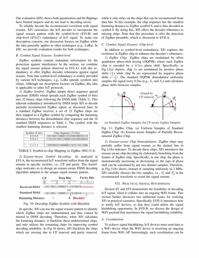
1) ZigBee Chip: ZigBee chips are modulated by offsetquadrature phase-shift keying (OQPSK) where each ZigBeechip is encoded by a 0.5us phase shift. Specifically, asFig.11(a) depicts, chip 1s are modulated by positive phaseshifts (π2 ) while chip 0s are represented by negative phaseshifts (−π2 ). The standard OQPSK demodulator uniformlysamples the signal every 0.5us (e.g., S1 and S2) and calculatesphase shifts between samples.
S1
S2
I
Q
I
Q
(a) Standard ZigBee Samples (b) CP-aware ZigBee Samples
1S¢
2S¢
Erased by
CP removal
Fig. 11: ZigBee Chip. (a) Uniform Samples of StandardZigBee Chip. (b) Erasure-aware Samples of Partially Recon-structed ZigBee Chip.
2) Erasure-aware Chip Demodulation: ZigBee chips maypartially suffer from signal erasure as the dashed line inFig.11(b) indicates. To decode these chips, XFi introduces theerasure-aware chip decoding by elaborately benefiting from thefeature of ZigBee chip. Specifically, in one chip, the phase ismonotonically increasing or decreasing, so the sign of phaseshift can be calculated by any two distinct samples. Therefore,as Fig.11(b) shows, instead of sampling uniformly in 2 MHz,XFi carefully chooses the two samples, i.e., S′1 and S′2 in thereconstructed waveform to avoid the signal erasure.
VII. PRACTICAL SIGNAL HITCHHIKING
Section §V and §VI demonstrate the feasibility of decodingIoT signal, when it collides into an ongoing WiFi frame. Thissection further discusses two additional issues for realizingXFi in practical scenarios. Specifically, §VII-A introduces howto notify IoT devices, so that they could utilize the signalhitchhiking opportunity. In §VII-B, we discuss the design ofWiFi payload that maximizes the signal hitchhiking reliability.
A. Coordination
To achieve signal hitchhiking, IoT devices must send data toa WiFi device when the WiFi device is receiving an ongoingframe from WiFi AP. Interestingly, such coordination can be

WiFi AP
WiFi Device
TX
RX
Rx TX
WiFi Preamble Cross-tech Polling Carrier of IoT Frames
t0 t1 t2t2+∆t t3
t0 t1 t2 t3
ZigBee/LoRa
Fig. 12: The downlink WiFi frame from AP consists of a cross-technology polling notification to IoT devices (t1 − t2) and acarrier of IoT signal (t2 − t3).
achieved by the WiFi frame itself. More specifically, we elab-orately select the WiFi payload such that the correspondingWiFi frame delivered by AP can simultaneously accomplish 3critical goals: (1) polls IoT devices to send data, (2) carriersIoT data into WiFi receiver, and (3) allocates IoT devices todistinct channels for avoiding collisions.
The WiFi frame structure and the complete signal hitch-hiking procedures are demonstrated in Fig.12. First, as alegitimate WiFi frame, the frame starts with WiFi preambleat t0. Upon the detection of the preamble, the WiFi radiobegins receiving and decoding, which provides an opportunityto capture the IoT signal. Second, the segment of WiFi payloadfrom t1 to t2 notifies the IoT devices of the opportunity ofsignal hitchhiking. In specific, XFi adopts WiFi→IoT CTCtechniques recently proposed in [30] to embed a legitimateZigBee or LoRa packet in the WiFi frame that contains a listof IoT devices to be queried and their allocated channels. Afterreceiving the notification, IoT devices tune the transmitterto the allocated channel, temporarily disable collision-avoidmechanism (e.g., CSMA), and then start transmissions att2 + ∆t. Narrowband IoT frames collide with the rest partof the WiFi frame, which carries them into the WiFi device.
Note that the WiFi frame and IoT frames do not need tobe strictly synchronized, as Fig.12 depicts. XFi reconstructsthe complete narrowband signal from t2 to t3, which is thenmatch-filtered with the predefined ZigBee or LoRa preambleto detect the beginning of IoT frames (i.e., t2 + ∆t).
R
f
Fig. 13: Power Spectrum and Channel Allocation.
B. Power Control
An issue arises immediately: High energy of WiFi cansaturate the WiFi subcarriers, leading to the corruption of IoT
frames. To address the problem, XFi introduces a power con-trol mechanism - by elaborately selecting the WiFi payload,we can minimize the WiFi energy on specific subcarriers. Inparticular, XFi carefully chooses the payload that producesWiFi signal from t2 to t3 in Fig.12, so that the subcarrierscapturing IoT signal take minimal values. By doing this, XFieffectively minimizes the WiFi energy at the frequency rangeswhere IoT frames hitchhike. Fig.13 depicts the visual powerspectrum density, where blue indicates low energy and yellowrefers to high energy. Obviously, several narrowbands withvisibly lower energy than other subcarriers (e.g., pilots) areproduced, thus improving the IoT signal’s signal-to-noise ratio.
With the power control, XFi utilizes WiFi spectrum with ex-tremely high efficiency. As the top of Fig.13 shows, we createtwo continuous 4 MHz channels and four 2 MHz channelsthat can pack 2 ZigBee frames or 8 LoRa frames. Besides,XFi carefully allocates guarding bands between channels tomitigate the interferences between channels. The evaluationdemonstrates that the power control mechanism effectivelycarries IoT data over WiFi transmission.
VIII. LIMITATION AND DISCUSSION
Implementation of XFi on smartphones. XFi works inWiFi software, so it is compatible with commodity WiFihardware in smartphones, requiring only a moderate driverupgrade. As a proof of concept, we prototype and evaluateXFi with commodity WiFi NIC in a Linux PC because itis convenient to patch Linux open-source WiFi drivers andobtain corrupted WiFi frames. WiFi drivers of smartphone areclose-source and need be patched with special patch tools (e.g.,NexMon [33]), which is left to future works.
Limitation of communication Range: XFi cannot supportlong range communications with IoT devices, which is becauseXFi can reconstruct IoT signals only when the signal is strongenough to corrupt WiFi packets. For long ranges, IoT signalscannot significantly interfere with WiFi packets due to thelimited transmission power of low-power IoT transmitters anduncertainty of the channel. As a result, IoT signals will beeliminated by error correction of LDPC decoder.
Generalization of XFi. The proposed approach in XFigenerally applies to other IoT techniques. To extend XFi toanother technique, one can directly adopt signal hitchhikingand waveform reconstruction to capture and reconstruct itswaveform while replacing the decoder (Section §VI) to onespecific to target technique. Additionally, it is possible toextend XFi to scenarios in other frequency bands, e.g., com-munication among WiFi 802.11ah and sub-GHz IoT devices.
XFi overhead. XFi introduces little overhead to WiFi andIoT network. Due to WiFi’s collision avoidance mechanism,i.e., CSMA, other WiFi traffic will back off when IoT framesare in transmission. Besides, XFi allows parallel data col-lection from multiple IoT devices to make efficient use ofWiFi’s wide spectrum. Finally, our coordination design inSection §VII is compatible with the receiver-initiated ZigBeeand LoRa protocol (e.g., [35]), so IoT devices can performduty cycle to minimize the overhead of idle listening.

IX. PERFORMANCE EVALUATION
This section evaluates XFi on commodity IoT and WiFi de-vices across various scenarios for demonstrating the reliability,efficiency, and generality of XFi.
CC2650
SX1280
RTL8812au
RTL8812auA6210 AR9380
ZigBee (COTS)
LoRa (COTS)
WiFi AP (COTS)
WiFi Device (COTS)
Fig. 14: Experimental Setting for XFi.
A. Evaluation Setup
We prototype XFi on the commercial off-the-shelf WiFiand IoT devices. The evaluation settings are depicted inFig.14. To demonstrate XFi’s compatibility, we evaluated iton Ubuntu 16.04 PC with three representative WiFi chipsetsfrom different brands: Mediatek A6210, Realtek RTL8812au,and Atheros AR9380. WiFi devices operate on channel 3 (2422MHz). ZigBee performance is evaluated with CC2650 ZigBeeSoC [38]. We develop ZigBee program using TI-RTOS SDK.Finally, LoRa is evaluated with SX1280 SoC [36] runningdefault PINGPONG example.
The evaluation starts with the overall performance of XFi.Then the detailed measurements of physical layers (i.e., Zig-Bee chip error rate and symbol error rate) are provided,followed by the link-layer experiments (i.e., frame receptionratio). To demonstrate the generality of XFi, we also evaluate iton LoRa. Each experiment is repeated 10 times, while 10000frames are received and the statistical results are obtained.Without further explanation, the distance between WiFi trans-mitter and receiver is 5 meters and the transmitter adopts 64QAM modulation, 5/6 coding rate, and 15 dBm transmissionpower. The distance between IoT devices and WiFi receivervaries from 2 meters to 15 meters, while the transmissionpower of IoT devices is 0 dBm.
TABLE II: Summary of XFi Performance.Commodity ZigBee LoRa
XFi Yes 285.7 Kbps 1.8 MbpsLego-Fi [18] No 213 Kbps Not SupportSymBee [39] No 31.25 Kbps Not Support
ZiFi [17] Yes 215.9 bps Not Support
B. Overall Performance
As we demonstrate in Table II, XFi is the first IoT→WiFicommunication design that simultaneously features 1) com-patibility with commodity WiFi hardware, 2) generality tovarious IoT technologies, and 3) high throughput. Specifically,XFi obtains IoT data entirely from decoded WiFi payload,whereas the state-of-the-art designs (e.g., Lego-Fi [18]) requireraw signal, which is incompatible with commodity devices.
Additionally, in contrast to previous works that are specificto ZigBee, XFi is first to be generally applicable to severaldistinct wireless techniques (e.g., LoRa), which is extremelybeneficial since IoT techniques are increasingly diversified.
With the capability of retrieving the legitimate payload dataof multiple IoT frames in parallel, XFi achieves a maximumthroughput of 285.7 Kbps for ZigBee and 1.8 Mbps for LoRa.The throughput of XFi significantly outperforms SymBee [39]and ZigFi [17] which rely on coarse-grained information ofsignal (e.g., correlation and CSI). Note that the latest WiFistandard (i.e., IEEE 802.11ax) provides 160 MHz bandwidth,which allows XFi to supports 16 parallel ZigBee devices andpotentially improves the overall throughput by 8 times.
0 50 100 150 200 250 300-2
0
2
Recovered By XFi
0 50 100 150 200 250 300-2
0
2
Standard ZigBee
Fig. 15: Reconstructed ZigBee vs. Standard ZigBee.
C. PHY Layer Performance
XFi introduces waveform reconstruction (Section §V) torecover raw IoT waveforms from decoded WiFi payload. Toevaluate the accuracy, we compare the reconstructed ZigBeesignal with the standard one. As Fig.15 illustrates, the narrow-band signal recovered by XFi approximates the standard onewell for the most of the time except those signal erased bythe WiFi receiver amid CP removal and parity removal.
0 1 2 3 4 5 6 7 8 9 10
Hamming Distance
05
10152025303540
Pro
bab
ilit
y(%
)
ZigBee#1
0 1 2 3 4 5 6 7 8 9 10
Hamming Distance
05
10152025303540
Pro
bab
ilit
y(%
)
ZigBee#2
(a) CER: ZigBee Channel 1 (b) CER: ZigBee Channel 2
Fig. 16: Chip Error Distribution in ZigBee Symbols.
We quantify the accuracy of the reconstructed waveformby examining the demodulated chips. In this experiment, twoZigBee devices transmit on parallel channels in Fig.13, whilethe distance between ZigBee transmitters and WiFi receiver is2 meters. The distributions of chip errors are depicted in theFig.16. Over 90% of symbols have less than 3 chips errors,which can be tolerated by DSSS. In addition, these two streamsof Zigbee signal demonstrate similar chip error distribution,showing that XFi can obtain multiple ZigBee transmissionsfrom WiFi payload and independently decode them in parallel.
2 4 8 10 15
Distances(m)
0
5
10
15
20
25
30
SE
R(%
)w/ backlist
w/o backlist
2 4 8 10 15
Distances(m)
0
5
10
15
20
25
30
SE
R(%
)
w/ backlist
w/o backlist
(a) SER: ZigBee Channel 1 (b) SER: ZigBee Channel 2
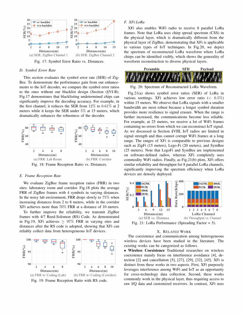
Fig. 17: Symbol Error Ratio vs. Distances.
D. Symbol Error Rate
This section evaluates the symbol error rate (SER) of Zig-Bee. To demonstrate the performance gain from our enhance-ments to the IoT decoder, we compare the symbol error ratiosto the ones without our blacklist design (Section (§VI-B).Fig.17 demonstrates that blacklisting undetermined chips cansignificantly improve the decoding accuracy. For example, inthe first channel, it reduces the SER from 12% to 0.61% at 2meters while it keeps the SER under 5% at 15 meters, whichdramatically enhances the robustness of the decoder.
2 4 6 8
Distance(m)
40
60
80
FRR(%)
2 4 6 8 10
Distance(m)
40
60
80
FRR(%)
Fig. 18: Frame Reception Ratio vs. Distances.
E. Frame Reception Rate
We evaluate ZigBee frame reception ratios (FRR) in twosites: laboratory room and corridor. Fig.18 plots the averageFRR of ZigBee frames with 4 symbols in varying distances.In the noisy lab environment, FRR drops slowly to 75% whenincreasing distances from 2 to 8 meters, while in the corridorXFi achieves more than 70% FRR at a distance of 10 meters.
To further improve the reliability, we transmit ZigBeeframes with 4/7 Reed-Solomon (RS) Code. As demonstratedin Fig.19, XFi achieves ≥ 97% FRR in varying sites anddistances after the RS code is adopted, showing that XFi canreliably collect data from heterogeneous IoT devices.
2 4 6 8
Distance(m)
90
95
100
FRR(%)
2 4 6 8 10
Distance(m)
90
95
100
FRR(%)
(a) FRR w/ Coding (Lab) (b) FRR w/ Coding (Corridor)
Fig. 19: Frame Reception Ratio with RS code.
F. XFi:LoRa
XFi also enables WiFi radio to receive 8 parallel LoRaframes. Note that LoRa uses chirp spread spectrum (CSS) inthe physical layer, which is dramatically different from thephysical layer of ZigBee, demonstrating that XFi is applicableto various types of IoT techniques. In Fig.20, we depictthe spectrum of reconstructed LoRa waveform where LoRachirps can be identified visibly, which shows the generality ofwaveform reconstruction to diverse physical layers.
Preamble SFD Payload
Fig. 20: Spectrum of Reconstructed LoRa Waveform.
Fig.21(a) shows symbol error ratios (SER) of LoRa invarious seettings. XFi achieves low error ratio (< 0.5%)within 15 meters. We observe that LoRa signals with a smallerbandwidth are most robust because a longer symbol durationprovides more resilience to signal erasure. When the range isfurther increased, the communications become less reliable.For example, at 25 meters, we receive a lot of WiFi framescontaining no errors from which we can reconstruct IoT signal.As we discussed in Section §VIII, IoT radios are limited insignal strength and thus cannot corrupt WiFi frames at a longrange. The ranges of XFi is comparable to previous designssuch as ZigFi (15 meters), Lego-Fi (20 meters), and SymBee(25 meters). Note that LegoFi and SymBee are implementedon software-defined radios, whereas XFi completely usescommodity WiFi radios. Finally, as Fig.21(b) plots, XFi offerssimilar reliability and throughput for 8 parallel LoRa channels,significantly improving the spectrum efficiency when LoRadevices are densely deployed.
3 6 9 12 15
Distance(m)
0
0.2
0.4
SE
R(%
)
1625K
812K
406K
203K
1 2 3 4 5 6 7 8
LoRa Channel
0
200
400
Data
Ra
te(K
bp
s) 1625K
812K
406K
203K
Fig. 21: LoRa Performance (Spreading Factor = 5).
X. RELATED WORKThe coexistence and communication among heterogeneous
wireless devices have been studied in the literature. Theexisting works can be categorized as follows.• Wireless Coexistence Traditional researches on wirelesscoexistence mainly focus on interference avoidance [4], de-tection [2] and cancellation [5], [27], [29], [32], [45]. XFi isdistinct from these works in two aspects. First, XFi purposelyleverages interference among WiFi and IoT as an opportunityfor cross-technology data collection. Second, these workscommonly work in the physical layer, thus requiring access toraw I/Q data and customized receivers. In contrast, XFi uses
the decoded WiFi payload, so it is only a software upgradethat is compatible with commodity WiFi devices.• Cross-technology Communication Cross-technology com-munication technologies (CTC) enable direct data exchangesamong heterogeneous wireless techniques. Early CTC designsmanipulate sparse packet-level information (e.g., the packetduration [8], [20], [43], interval [26], energy pattern [10],[16], [23], [41], and energy level [11], [17], [19], [44]) todeliver messages among heterogeneity. Among these works,B2W2 [11] and ZigFi [17] enable low-power IoT radios tosend messages to WiFi by intentionally interfering WiFi CSI.However, due to the sparsity of CSI information, these designsare intrinsically restricted in the data rate.
XFi belongs to recent advances of physical-layer CTC [9],[12], [30], [31], [40], [42], which significantly improve thedata rate by directly delivering messages via payload. The pi-oneering work (WEBee [30]) introduces signal emulation thatenables WiFi radio to send legitimate ZigBee frames. Despiteits success, signal emulation only applies to high-speed radios(e.g., WiFi), so it cannot enable a WiFi radio to collect datafrom ZigBee. To tackle the problem, SymBee [39] and LEGO-Fi [18] propose to decode ZigBee signal in the WiFi device.However, they modify WiFi demodulation procedures, thuscannot be deployed on commodity WiFi hardware. Besides,their designs are tightly coupled with the unique featuresof ZigBee signal and thus cannot be generalized to otherwireless techniques (e.g., LoRa). In contrast, XFi is the first“IoT→WiFi” CTC that entirely uses commodity WiFi radiosand our “reconstruct and decode” technique is also the firstgeneral method that can be extended to other IoT technologies.CTC among various IoT technologies (e.g., ZigBee, BLE andLoRa) [22], [24], [28], [37] and CTC between WiFi andLTE [7] are also proposed. These works are either based onsignal emulation or unique features of these wireless protocols.Therefore, they cannot be generalized to “IoT→WiFi CTC”(i.e., address communication from low-speed radio to high-speed WiFi). They also do not address the unique challengesof a WiFi radio (e.g., channel decoding and signal erasure).Finally, using mobile devices as IoT gateways is discussed in[1], which only considers homogeneous wireless techniques.
XI. CONCLUSIONThis paper proposes XFi, the first work that achieves cross-
technology data collection using commodity WiFi hardware.We envision that XFi will inspire ubiquitous interactionsbetween mobile devices and heterogeneous IoT systems.
XII. ACKNOWLEDGE
This work was supported by the NSF CNS-1525235, NSFCNS-1718456, NSF CNS-1717059 and SRG ISTD 2020159.We sincerely thank the shepherd and reviewers for theirvaluable comments.
APPENDIX
This section theoretically proves our observation in thesection V-B that LDPC decoder is ineffective when decodinghitchhiking IoT signal that incurs excessive bit errors.
Proof. The proof is based on sum-product algorithm [25],which is commonly used in LDPC decoder for its high effi-ciency. Sum-product calculates the a posteriori log-likelihoodratio (LLR) Li for each bit i as defined in Equation 1 wherebit i is decided to be one when Li ≤ 0 and zero when Li ≥ 0.
Li = logp(xi = 0)
p(xi = 1)= ri +
∑j∈Ai
Ej,i (1)
Li is the sum of ri (the initial LLR from the input) and Ej,i(the extrinsic LLR from the jth parity check to bit i). Since abit is flipped when the sum of extrinsic LLRs is large enoughso that the initial LLR (ri) and a posteriori LLR (Li) takedifferent signs, the probability of flip (Pe) can be expressedas a conditional probability in Equation 2. The decoder isineffective if Pe is extremely small for any bit.
Pe = P (Li ≤ 0|ri ≥ 0) = P (Li ≥ 1|ri ≤ 1) (2)
As Equation 3 shows, the initial LLR ri only depends onthe received value of bit i denoted as xi, where the crossoverprobability p is prior knowledge of the decoder.
ri = logP (xi = 0)
P (xi = 1)=
{log p
1−p xi = 1
log 1−pp xi = 0
(3)
Since ri ≥ 0 is equivalent to xi = 0 and vice versa, Pe inEquation 2 can be deduced into Equation 4.
Pe = P (ri +∑j∈Ai
Ej,i ≤ 0|xi = 0)
= P (∑j∈Ai
Ej,i < logp
1− p)
(4)
log p1−p is constant, so the calculation of Pe is reduced to
find the distribution of∑j∈Ai
Ej,i. As Equation 5 shows, eachextrinsic LLR Ej,i is computed from all bits associated withjth parity check except for bit i (denoted as bit i′), wherepi′ = P (xi′ = 1) is the probability that the true value of biti′ is one.
Ej,i = log(
12 + 1
2
∏i′∈Bj ,i′ 6=i(1− 2pi′)
12 −
12
∏i′∈Bj ,i′ 6=i(1− 2pi′)
) (5)
Our key insight is that coded bits in severely corrupted WiFipayload are almost uncorrelated from each other, meaning thatp′is are i.i.d random variables that take value either p or 1−pwith 1
2 probability. Therefore, Ej,i is simply a discrete randomvariable shown in Equation 6, where e is a constant calculated
as e = log(12+
12
∏i′∈Bj,i
′ 6=i(1−2p)12−
12
∏i′∈Bj,i
′ 6=i(1−2p)).
f(Ej,i) =
{12 Ej,i = e12 Ej,i = −e
(6)
Importantly, e � log p1−p . Typically, p = 0.9 and log p
1−p= 2.2, while e is less than 0.001. Since corrupted coded bitsare highly uncorrelated, Ej,is are approximately independentof each other and can also be modeled as i.i.d. Thus, the sumof extrinsic LLR is very unlikely to be large enough to flipthe sign of LLR. When p = 0.9, Pe ≈ 0.1%. Note that theexperiment shows a slightly higher probability because Ej,isare not completely independent. Our observation in Section§V-B is proved.
REFERENCES
[1] M. Abdelaal, M. Dandy, F. Durr, K. Rothermel, and M. Abdelgawad.Gaas: Adaptive cross-platform gateway for iot applications. In 2019IEEE 16th International Conference on Mobile Ad Hoc and SensorSystems (MASS), pages 217–226, 2019.
[2] F. Adib, S. Kumar, O. Aryan, S. Gollakota, and D. Katabi. Interferencealignment by motion. In Proceedings of ACM MobiCom, 2013, 2013.
[3] advantech.com. advantech IoT Gateway. http://select.advantech.com/iotgateway/, 2019.
[4] G. Baig, I. Kash, B. Radunovic, T. Karagiannis, and L. Qiu. Interferencemanagement for unlicensed users in shared cbrs spectrum. In Pro-ceedings of the 14th International Conference on emerging NetworkingEXperiments and Technologies, pages 333–345, 2018.
[5] T. Bansal, B. Chen, P. Sinha, and K. Srinivasan. Symphony: Cooperativepacket recovery over the wired backbone in enterprise wlans. InProceedings of the 19th annual international conference on Mobilecomputing & networking, pages 351–362. ACM, 2013.
[6] P. R. Center. Internet/Broadband Fact Sheet. https://www.pewresearch.org/internet/fact-sheet/internet-broadband/, 2019.
[7] E. Chai, K. Sundaresan, M. A. Khojastepour, and S. Rangarajan. Ltein unlicensed spectrum: Are we there yet? In Proceedings of the 22ndAnnual International Conference on Mobile Computing and Networking,pages 135–148. ACM, 2016.
[8] K. Chebrolu and A. Dhekne. Esense: communication through energysensing. In Proceedings of ACM MobiCom 2009, 2009.
[9] Y. Chen, Z. Li, and T. He. Twinbee: Reliable physical-layer cross-technology communication with symbol-level coding. In Proceedingsof IEEE INFOCOM 2018, 2018.
[10] Z. Chi, Z. Huang, Y. Yao, T. Xie, H. Sun, and T. Zhu. Emf: Embeddingmultiple flows of information in existing traffic for concurrent com-munication among heterogeneous iot devices. In Proceedings of IEEEINFOCOM 2017.
[11] Z. Chi, Y. Li, H. Sun, Y. Yao, Z. Lu, and T. Zhu. B2w2: N-wayconcurrent communication for iot devices. In Proceedings of ACMSensys 2016, 2016.
[12] Z. Chi, Y. Li, Y. Yao, and T. Zhu. Pmc: Parallel multi-protocolcommunication to heterogeneous iot radios within a single wifi channel.In 2017 IEEE 25th International Conference on Network Protocols(ICNP), pages 1–10. IEEE, 2017.
[13] cisco.com. Cisco Global Cloud Index: Forecast and Methodology.https://www.cisco.com/c/en/us/solutions/collateral/service-provider/global-cloud-index-gci/white-paper-c11-738085.html, 2019.
[14] S. Clark. TazTag unveils first Android phone with NFCand ZigBee. https://www.nfcw.com/2012/02/26/313800/taztag-unveils-first-android-phone-with-nfc-and-zigbee/, 2012.
[15] eMarketer. US Adult Wearable Users and Penetration. https://www.emarketer.com/content/wearables-2019, 2018.
[16] P. Gawlowicz, A. Zubow, and A. Wolisz. Enabling cross-technologycommunication between lte unlicensed and wifi. In IEEE INFOCOM2018-IEEE Conference on Computer Communications, pages 144–152.IEEE, 2018.
[17] X. Guo, Y. He, X. Zheng, L. Yu, and O. Gnawali. Zigfi: Harnessingchannel state information for cross-technology communication. InProceedings of IEEE INFOCOM 2018, 2018.
[18] X. Guo, Y. He, X. Zheng, Z. Yu, and Y. Liu. Lego-fi: Transmitter-transparent ctc with cross-demapping. In IEEE INFOCOM 2019-IEEEConference on Computer Communications, pages 2125–2133. IEEE,2019.
[19] X. Guo, X. Zheng, and Y. He. Wizig: Cross-technology energy com-munication over a noisy channel. In Proceedings of IEEE INFOCOM2017.
[20] R. Hofmann, C. A. Boano, and K. Romer. X-burst: Enabling multi-platform cross-technology communication between constrained iot de-vices. In 2019 16th Annual IEEE International Conference on Sensing,Communication, and Networking (SECON), pages 1–9, 2019.
[21] iPass. The Rise of Wi-Fi First. https://www.ipass.com/wp-content/uploads/2017/03/iPass-White-Paper-WiFi-First.pdf, 2017.
[22] W. Jiang, S. M. Kim, Z. Li, and T. He. Achieving receiver-side cross-technology communication with cross-decoding. In Proceedings ofthe 24th Annual International Conference on Mobile Computing andNetworking, pages 639–652. ACM, 2018.
[23] W. Jiang, Z. Yin, S. M. Kim, and T. He. Transparent cross-technologycommunication over data traffic. In Proceedings of IEEE INFOCOM,2017, 2017.
[24] W. Jiang, Z. Yin, R. Liu, Z. Li, S. M. Kim, and T. He. Bluebee: a10,000 x faster cross-technology communication via phy emulation. InProceedings of the 15th ACM Conference on Embedded Network SensorSystems, page 3. ACM, 2017.
[25] S. J. Johnson. Introducing low-density parity-check codes. Universityof Newcastle, Australia, page V1, 2006.
[26] S. M. Kim and T. He. Freebee: Cross-technology communication viafree side-channel. In In Mobicom, 2015.
[27] L. Kong and X. Liu. mzig: Enabling multi-packet reception in zigbee.In Proceedings of the 21st annual international conference on mobilecomputing and networking, pages 552–565. ACM, 2015.
[28] L. Li, Y. Chen, and Z. Li. Physical-layer cross-technology communi-cation with narrow-band decoding. In 2019 IEEE 27th InternationalConference on Network Protocols (ICNP), pages 1–2. IEEE, 2019.
[29] Y. Li, Z. Chi, X. Liu, and T. Zhu. Chiron: Concurrent high throughputcommunication for iot devices. In Proceedings of the 16th AnnualInternational Conference on Mobile Systems, Applications, and Services,pages 204–216. ACM, 2018.
[30] Z. Li and T. He. Webee: Physical-layer cross-technology communica-tion via emulation. In Proceedings of the 23rd Annual InternationalConference on Mobile Computing and Networking, pages 2–14. ACM,2017.
[31] Z. Li and T. He. Longbee: Enabling long-range cross-technologycommunication. In Proceedings of IEEE INFOCOM 2018, 2018.
[32] C.-J. M. Liang, N. B. Priyantha, J. Liu, and A. Terzis. Surviving wi-fi interference in low power zigbee networks. In Proceedings of the8th ACM Conference on Embedded Networked Sensor Systems, pages309–322. ACM, 2010.
[33] M. Schulz, D. Wegemer, and M. Hollick. Nexmon: The c-based firmwarepatching framework, 2017.
[34] Sears. 2.4GHz wireless digital video baby monitor. https://www.sears.com/xcsource-2.4-ghz-wireless-digital-video-baby/p-A026482260,2020.
[35] Semtech. Using the SX1280/SX1281 in Low Power Applications. https://www.semtech.com/products/wireless-rf/24-ghz-transceivers/sx1280,2019.
[36] Semtech. Semtech SX1280. https://www.semtech.com/products/wireless-rf/24-ghz-transceivers/sx1280, 2020.
[37] J. Shi, D. Mu, and M. Sha. Lorabee: Cross-technology communicationfrom lora to zigbee via payload encoding. In 2019 IEEE 27th Inter-national Conference on Network Protocols (ICNP), pages 1–11. IEEE,2019.
[38] TI. CC2650 SimpleLink™ 32-bit Arm Cortex-M3 multiprotocol 2.4GHz wireless MCU. https://www.ti.com/product/CC2650, 2020.
[39] S. Wang, S. M. Kim, and T. He. Symbol-level cross-technologycommunication via payload encoding. In 2018 IEEE 38th InternationalConference on Distributed Computing Systems (ICDCS), pages 500–510,July 2018.
[40] S. Wang, Z. Yin, Z. Li, and T. He. Networking support for physical-layer cross-technology communication. In 2018 IEEE 26th InternationalConference on Network Protocols (ICNP), pages 259–269, 2018.
[41] Z. Yin, W. Jiang, S. M. Kim, and T. He. C-morse: Cross-technologycommunication with transparent morse coding. In Proceedings of IEEEINFOCOM 2017, 2017.
[42] Z. Yin, Z. Li, S. M. Kim, and T. He. Explicit channel coordinationvia cross-technology communication. In Proceedings of ACM MobiSys2018, 2018.
[43] Y. Zhang and Q. Li. Howies: A holistic approach to zigbee assisted wifienergy savings in mobile devices. In Proceedings of IEEE INFOCOM2013, 2013.
[44] X. Zheng, Y. He, and X. Guo. Stripcomm: Interference-resilient cross-technology communication in coexisting environments. In Proceedingsof IEEE INFOCOM 2018, 2018.
[45] W. Zhou, T. Das, L. Chen, K. Srinivasan, and P. Sinha. Basic: backbone-assisted successive interference cancellation. In MobiCom ’16, pages149–161. ACM, 2016.


![A Breathing Beats with Commodity WiFi - arXiv.org e …1702.02046v1 [cs.CE] 6 Feb 2017 A TensorBeat: Tensor Decomposition for Monitoring Multi-Person Breathing Beats with Commodity](https://static.fdocuments.in/doc/165x107/5ad6cc267f8b9a98098bfcdc/a-breathing-beats-with-commodity-wifi-arxivorg-e-170202046v1-csce-6-feb.jpg)