xenon Gladiator Iii - Strong...
54
STRONG INTERNATIONAL a division of Ballantyne of Omaha, Inc. 4350 McKinley Street Omaha, Nebraska 68112 USA Tel 402/453-4444 • Fax 402/453-7238 www.strong-lighting.com XENON GLADIATOR III Follow Spotlight Type 47061 Rev. October 2005
-
Upload
vuongnguyet -
Category
Documents
-
view
217 -
download
3
Transcript of xenon Gladiator Iii - Strong...

STRONG INTERNATIONALa division of Ballantyne of Omaha, Inc.
4350 McKinley StreetOmaha, Nebraska 68112 USATel 402/453-4444 • Fax 402/453-7238www.strong-lighting.com
XENON GLADIATOR IIIFollow Spotlight
Type 47061
Rev. October 2005


PREFACE
THE STRONG INTERNATIONAL XENON GLADIATOR III Model 47061 is a direct cur-rent follow spotlight complete with a xenon lamphouse, power supply, optical system, color boomerang, andbase stand assembly. The spotlight assembly consists of the arc lamp, variable focus lens system, color boomer-ang, and base. The separate xenon power supply completes the installation.
ONLY THE SPECIAL XENON POWER SUPPLIES manufactured by Strong Internationalcan be used with the Gladiator III. For installation and operation of the power supply, see the instructionmanual furnished separately.
THE XENON LAMPHOUSE utilizes a 3000 watt xenon bulb designed for horizontal opera-tion, and a deep ellipse metal reflector, as a light source. The reflector is designed to operate in a fixed position,and is dichroic (“cold”) coated to reduce heat in the projected light. A lens blower and heat filters, mounted inthe spotlight optical system, further reduce heat at the projection lens and color media.
ONLY XENON BULBS designed for horizontal operation should be used in this follow spot.The Gladiator III lamphouse is designed to use the LTIX-3000W-H xenon theater bulb, and replacement bulbsmust be certified as 100% interchangeable with this type. All required bulb cabling is provided in the xenonlamphouse or supplied with the bulb, and bulb adapters are not required.
ADJUSTMENT CONTROL for the xenon bulb is located at the rear of the lamphouse behindthe access panel. The adjustments control the horizontal, vertical and focal movement of the bulb.
INSTRUMENTATION of the lamphouse includes a running time meter and a DC ammeter.The running time meter indicates the number of hours the bulb has been in operation. The ammeter displays theoperating current of the lamp. A push button switch, located below the ammeter, changes the meter reading toindicate the DC voltage at the arc.
THE LAMPHOUSE COOLING BLOWERS are internally wired and operate on AC voltagederived from the xenon power supply. These blowers are required to maintain a safe operating temperature atthe bulb seals. The blowers operate continuously until the xenon power supply is de-energized. Air flowinterlock switches prevent operation of the lamp if the intake or exhaust blowers are not operating or failing tomove adequate air.
THE IGNITER is equipped with an emergency ignition switch, located on the top of the lamp-house below the plug button. Pressing this switch bypasses the relay contacts on the igniter printed circuitboard. DO NOT hold this switch for longer than one second to prevent transformer damage.
THE TWO ROCKER SWITCHES on the instrument panel are labeled MODE and LAMP.The MODE switch permits operation of the lamphouse from a remote location when placed in the “AUTO”position, or by the operator at the lamphouse when in “MAN.” The normal setting for this switch, in a followspot application, is in the “MAN.” position.
THE LAMP SWITCH is provided for manual bulb ignition when the MODE switch is in the“MAN.” position. The LAMP switch must also be “ON” to complete the ignition circuit when operating froma remote location.
XG3/001

THE LAMPHOUSE is supplied with a 13 foot cable containing the DC leads, the AC controlwires, and the ground wire. The cable terminates in a multiple pin MS connector keyed to mate with thereceptacle on the power supply.
WHEN TRANSPORTING THE SPOTLIGHT, it is necessary to remove the xenon bulb andplace it in its original shipping container to prevent breakage. See the SAFETY PROCEDURES sectionfollowing, and permit only authorized personnel to handle the xenon bulb.
IF AT ANY TIME you have a suggestion, or desire aid in securing anticipated results, writedirectly to STRONG INTERNATIONAL, 4350 McKinley Street, Omaha, Nebraska 68112.
XG3/002

INSTALLATION AND SETTING UP SPOTLIGHT
THE XENON GLADIATOR III is shipped in sections which must be assembled. Liftingstraps on the yoke assembly permit assembling the spotlight on the floor and later hoisting it to an elevatedposition.
ASSEMBLE THE FOUR BASE LEGS to the lower square section of the base column usingthe 3/8-16 x 2-3/4 inch hex head cap screws and lockwashers provided. Insert a leveling foot and locknut ineach of the four leg brackets and level the base before continuing the installation.
WHEN INSTALLED in a permanent location, the leveling feet must be removed, and theclearance holes in the base leg brackets used for hardware (user supplied) to bolt the base to the floor orplatform. If it is desired to have the unit portable, when operating, the leveling feet must be adjusted down untilthe weight of the spotlight has been shifted from the casters to the leveling feet.
THE INNER TUBE and support yoke has three holes to permit adjusting the height of thespotlight. The three holes are on four inch centers and will allow an optical height of approximately 53 inches,57 inches, and 61 inches above floor level to the optical center of the lamphouse and lens system. Insert theheight location pin through the hole in the outer tube and one of the holes in the inner tube. The leveling feetmay be adjusted through an additional two inch range.
THE HORIZONTAL SWING and vertical tilt locking knobs are on the right hand (operating)side of the yoke assembly. Tighten both of these locking devices securely before attempting to place the lamp-house and lens system on the support yoke.
PLACE THE LAMPHOUSE and lens system on the yoke assembly, with the spot size controlhandle to the right hand (operating) side, the same as the locking controls on the yoke. Line up the fourmounting holes in the bottom of the base rail with the four mating holes in the support yoke and secure using thefour sets of 3/8-16 screws, nuts and washers.
ATTACH THE LAMPHOUSE CABLE CONNECTOR to the mating receptacle on the powersupply. The lamphouse and power supply connectors are keyed for correct pin alignment; make certain pins areseated before tightening the locking ring. Check the position of the slide switch adjacent to the MS connector;it must be in the proper setting for “Lamphouse/Spotlight”. See the inside front cover of the power supplymanual. DO NOT energize the xenon power supply before the xenon bulb is correctly installed into the lamphouse.
EARLIER MODELS of Strong xenon spotlights included a heavy-gauge green ground wire inthe lamphouse cable assembly. This ground wire was attached to a ground stud connected to the power supplycabinet. Current models of Strong power supplies include a 1/4-20 stud in the cabinet adjacent to the MSconnector to allow ground termination of older spotlights.
XG3/003

LAMPHOUSE - POWER SUPPLYInterconnection Diagram
LAMPHOUSE(Connections Pre-wired)
MS CONNECTORPin Wire No, A DC- B DC+ C 2 D 3 E 4 F 5 G 6 I 7 J 8 M Grnd
LamphouseCable Assembly
Conduit
Remote - AutoSustained 5 Amp.
Dry Contact(by Installeras req’d.)
XENONPOWERSUPPLY
MS Connector (pre-wired)DC+DC-
XG3/004
SYSTEM MUST BE GROUNDEDAll wiring must conform to local
codes; shield lamphouse cable inconduit if required.
Check Slide Switch (below) on PowerSupply for correct positioning.
Slide to LEFT

SAFETY PROCEDURES
READ CAREFULLY BEFORE INSTALLING XENON BULB
THE XENON BULB is highly pressurized. When ignited, the normal operating temperatureof the bulb increases the pressure to a level at which the bulb may explode if not handled in strict accordance tothe manufacturer’s operating instructions.
THE BULB is stable at room temperature, but may still explode if dropped or otherwise mis-handled. Breakage resulting from transport and handling is not covered by the bulb manufacturer’s warranty,and it is strongly recommended to dismount the xenon bulb when transporting the spotlight.
REFER bulb replacement and service to QUALIFIED PERSONNEL with adequate protectiveclothing (face shield, clean cotton gloves, welder’s jacket). For routine lamphouse service, observe the follow-ing rules:
1. Allow the bulb to cool to room temperature before opening the lamphouse. Put on protective clothingdescribed above.
2. De-energize the xenon power supply at the AC source before opening the lamphouse compartment.
3. When possible, encase the bulb in its protective cover when cleaning or servicing the lamphouse inte-rior. The bulb, when outside the lamphouse, must be encased in the cover.
4. Clean the bulb after it has cooled to room temperature. Do not touch the quartz envelope of the bulb;fingerprints will burn in and create hot spots which may shorten bulb life. If fingermarks are made,they should be carefully removed with methyl alcohol and cotton prior to bulb operation.
5. Never view an ignited bulb directly. BLINDNESS OR PERMANENT EYE DAMAGE MAY BEINCURRED.
6. Use only xenon bulbs designated as OZONE FREE. When possible, vent the lamphouse exhaust tooutside atmosphere.
7. Maintain the lamphouse blower in good operating condition. Keep the blower inlet clean for unre-stricted air flow.
8. To insure maximum bulb life, operate the lamphouse blower and the exhaust system for at least tenminutes after extinguishing the bulb.
9. If returning a bulb for warranty adjustment, pack it in its original shipping container. Complete andreturn all required warranty information.
XG3/005
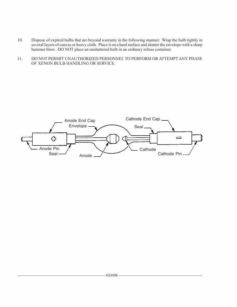
10. Dispose of expired bulbs that are beyond warranty in the following manner: Wrap the bulb tightly inseveral layers of canvas or heavy cloth. Place it on a hard surface and shatter the envelope with a sharphammer blow. DO NOT place an unshattered bulb in an ordinary refuse container.
11. DO NOT PERMIT UNAUTHORIZED PERSONNEL TO PERFORM OR ATTEMPT ANY PHASEOF XENON BULB HANDLING OR SERVICE.
Cathode PinCathode
AnodeAnode Pin
Cathode End Cap
Seal
SealEnvelopeAnode End Cap
XG3/006

BULB INSTALLATION
OBSERVE ALL SAFETY PROCEDURES when working around the xenon bulb. Open thelamphouse access door by releasing the key lock and removing the tamperproof screws using the special screw-driver supplied. The igniter lead and contact clamp are tied off for shipping. Free the clamp and slide it over therear bulb support collet. Attach the cathode lead to the cathode end cap, if not factory-installed.
REMOVE THE PLASTIC PROTECTIVE COVER from the xenon bulb only if necessary.Handle the bulb by the metal end caps only. Insert the bulb into the lamphouse, passing the anode (+) end capthrough the center hole of the reflector. Take care not to bump or scratch the surface of the reflector.
INSERT THE ANODE (+) PIN into the rear support collet and contact clamp. Rest thecathode (-) end cap in the front bulb support yoke. Seat the anode (+) pin into the rear support collet as far aspossible for correct focus travel. Securely tighten the socket head clamping screw in the anode contact.
REST THE CATHODE END CAP in the “V” of the bulb yoke. Insulate the cathode bulb leadusing the length of silastic rubber tubing supplied. Dress the bulb lead directly in front of the bulb support yoketo minimize the projected shadow. Attach the ring terminal on the end of the bulb lead to the negative bindingpost inside the operator’s access door. Securely tighten the 3/8-16 hexnut.
REMOVE THE PLASTIC COVER from the bulb. Record the bulb serial number, date, andlamphouse hours on the Xenon Bulb Record on the inside back cover of this manual. This information will beneeded in the event of a bulb warranty adjustment.
XG3/007

ESTABLISH A ROUTINE of periodically checking all electrical connections for tightness.Loose contacts, particularly in the DC circuit, will cause overheating and damage the xenon bulb and othercomponents. Normal xenon bulb warranties allow no credit for bulb damage caused by overheating.
REFER TO THE BULB MANUFACTURER’S INSTRUCTIONS regarding bulb rotation.Most bulb manufacturers recommend rotating the bulb 180° at 50% of warranty hours. After rotating the bulb,operate at maximum allowable current for several hours, and then return to the nominal operating current.
IN THE EVENT of a bulb warranty claim, the bulb must be packaged in its original shippingcontainer, and returned with all required warranty forms completed. Contact the dealer through whom the bulbwas originally purchased for correct procedures and Return Authorizations.
IT IS A COMMON PRACTICE to replace the bulb at the expiration of its warranty period. Ifa xenon bulb explodes in operation, the reflector and other lamphouse components are frequently damaged. Thexenon bulb manufacturer will extend no credit for a replacement reflector if the defective bulb is beyond war-ranty. Explosion-damaged reflectors are to be returned to the bulb supplier, NOT Strong International, unlessthe bulb was supplied by Strong.
XG3/008
ARC STABILIZATION MAGNET
THE XENON BULB used in the Gladiator III lamphouse requires an arc stabilization magnet.This magnet is located on the lamp base behind the reflector. This magnet is preset at the factory and shouldnot require adjustment. Should it become necessary to adjust the magnet, the following procedure must befollowed. Observe all bulb safety procedures when working in the lamphouse compartment.
THE NORMAL ARC, when viewed through the arc viewing port, will appear as in Figure“A.” This represents the correct magnet position. Figure “B” shows the position of the arc when the magnetis too low. Raise the magnet on its adjustment bracket to lower the arc to the position illustrated in Figure “A.”Figure “C” shows the position of the arc when the magnet is too high. Lower the magnet to raise the arc tothe position illustrated in Figure “A.”
THE MAGNET must always be installed with the longest portion of the magnet nearestthe bulb, and with the NORTH (N) pole pointing to the operator side access door. Reversing the magnet willcause bulb flicker, and may inhibit bulb ignition. In new equipment, the magnet is normally in the center of theadjustment range. Changes in the magnet position are required only to correct an improperly burning arc(Figure “B” or “C”).
ANY REPLACEMENT MAGNET should first be installed in the center position of theadjustment range. Raise or lower the magnet as required to center the arc as illustrated in Figure “A.”

OPERATION
INSTALL THE GLASS HEAT FILTER into the bracket mounted on the rear of the fadeoutand douser support housing. NOTE: The coated side of the filter, with the XX or other marking, must befacing the reflector. Reach through the side door and nose opening of the lamphouse, slide the filter into the slotin the top angle bracket, and lower it into the bottom slotted bracket.
REMOVE THE PLASTIC COVER from the xenon bulb. DO NOT ignite the lamp with thecover on the bulb. Store the cover for future re-use.
CLOSE AND SECURE the lamphouse door using the tamperproof screws and special screw-driver supplied with the lamphouse. Engage the cam lock and install the security screw. The door must becompletely secured to actuate the interlock switch and permit lamp ignition. Place the MODE switch in the“MAN.” (manual) position.
TURN ON THE MAIN LINE SWITCH and/or circuit breaker to energize the xenon powersupply. The lamphouse blowers will start and the blower interlock switches will be actuated to permit lampignition. The blowers will operate continuously until the xenon power supply is de-energized.
PLACE THE LAMP SWITCH in the “ON” position and the lamp will ignite. If ignition doesnot occur, or the high voltage pulse is not apparent, press the emergency ignition switch on the top of thelamphouse under the plug button. Do not hold more than one second; release immediately upon lamp ignition.Use of the emergency ignition switch indicates an abnormal condition; see the TROUBLESHOOTING sectionfollowing.
CHECK THE READING on the lamphouse ammeter. Nominal current for the 3000 wattxenon bulb is 95 amperes. DO NOT, AT ANY TIME, exceed 100 amperes. Output current is adjusted at thepower supply; see power supply manual for instructions. Operation of a new bulb is normally started at thelower end of its range (85 A.), and current is gradually increased as the bulb ages to maintain light output.
PRESS THE SMALL PUSH BUTTON SWITCH located below the ammeter to read the DCvoltage at the arc. This permits immediate calculation of the power at which the lamp is operating (volts timesamperes = wattage). Holding this switch in during the ignition cycle will also briefly indicate the “no load”(open circuit) DC voltage applied to the xenon bulb for ignition.
REMOVE THE REAR COVER PLATE below the instrument panel by withdrawing the twoplastic plungers. This exposes the bulb positioning controls in the lamphouse back casting.
TO FOCUS THE XENON BULB and obtain the best light on the stage, the two methodsoutlined below are the most suitable.
MOVE THE SPOT SIZE CONTROL HANDLE (trombone) on the large lens carriage all theway forward to project the smallest spot possible; place the iris, masking shutters (choppers) and the fadeoutdouser blades in their full open positions. Project a spot to a wall or similar flat perpendicular surface oppositethe spotlight position.
XG3/009

THE CENTER SECTION of the bulb positioning controls is a threaded member that focusesthe bulb in relation to the reflector. Turning this adjustment moves the bulb in only one plane, into or away fromthe reflector. Turning this section clockwise moves the bulb away from the reflector. The small knurled screwto the left of this section can be tightened to lock the focusing mechanism after the following procedures havebeen completed.
THE LARGE THUMB SCREWS, on either side of the focusing control, lock the horizontaland vertical adjustment mechanism in position.
TURN THE CENTER FOCUSING SECTION of the bulb positioning control counterclock-wise until a small black spot is projected onto the wall. It may be best to run this adjustment both directions topermit positive identification of the spot.
LOOSEN THE TWO THUMB SCREWS, one on either side of the center focusing section,just enough to permit manual movement of the complete assembly. The bulb positioning control will now movearound these two thumb screws, and as this control is shifted, the smooth shadow of the bulb electrode can beseen extending beyond the projected center hole in the reflector. The shadow of the electrode (black spot) mustbe centered in the projected hole of the reflector (shaded, less dense dark area).
MOVE THE CONTROL SECTION around the two screws until the black spot is as round aspossible to project. It may be necessary to again turn the focus control to project a sharply defined black spot.
AFTER THE BLACK SPOT is as even around the outside as possible to project, and appearscentered in the shaded reflector center hole, tighten the two large thumb screws to lock the position of themechanism. Turn the center focus control to obtain the brightest light with the best light distribution. Rotate thelens spot focus control knob, located at the extreme front of the lens mechanism, to obtain the sharpest edgepossible on the projected spot.
THE SECOND METHOD of focusing the xenon bulb is to project the spot to the stage, andworking with the above lamphouse controls, adjust these controls to obtain a “hot spot” on the projected spot.Then center this “hot spot” on the projected light by moving the entire control section around the two thumbscrews. Once this “hot spot” is centered in the projected light, lock the control in position with the two thumbscrews and turn the center section to obtain a spot with an even distribution of light. Rotate the lens spot focuscontrol knob to obtain a sharp edge on the projected spot.
XG3/010

THESE ADJUSTMENTS should not be disturbed until it is necessary to replace the xenonbulb. At that time, the procedure on obtaining a smooth, round black spot, or “hot spot,” may have to berepeated. Replace the cover plate over the bulb positioning controls.
BECAUSE OF NORMAL BULB AGING, and manufacturing tolerances between individualxenon bulbs, it may be necessary to operate lamps at slightly higher or lower current settings to maintainuniform light output when two or more spotlights are used in one installation. This entails a slight currentoutput adjustment at the xenon power supplies. See the power supply manual.
TO EXTINGUISH the arc, place the LAMP switch on the instrument panel to “OFF.” Thelamphouse blowers will continue to operate until the xenon power supply is de-energized. Allow the blowers tooperate for ten minutes before turning off the power supply; a forced-air bulb cooling cycle is required by allbulb manufacturers.
DAILY OPERATION in the “Manual” mode requires only that the xenon power supply beenergized, the MODE switch be left in the “MAN.” position, and the lamp switched ON and OFF by means ofthe LAMP switch. No bulb alignment or “warm up” are necessary. Always allow for the ten minute bulbcooling cycle.
OPERATION IN THE “AUTO” MODE is intended for use only if the spotlight is to be used asa fixed spot without an operator at the equipment. Place the MODE switch in the “AUTO” position, and theLAMP switch to “ON.” The lamp will ignite when a sustained dry contact is made between the automationleads 3 and 6, and extinguish when the contact is opened. See the INSTALLATION DIAGRAM in the powersupply manual. The lamphouse blowers will operate until the xenon power supply is de-energized; allow for tenminutes bulb cooling.
BEFORE OPENING the lamphouse enclosure for servicing, allow the blowers to operate fortwenty minutes, or until the bulb has cooled to room temperature.
HANDLING THE SPOTLIGHT
GENERALLY THE BEST POSITION for the operator to stand is hear the center of the spot-light on the right side. The angle of tilt, the size of the porthole, and the layout of the spotlight position maydictate another location.
EACH OPERATOR will, after a few minutes of operation, generally develop his own systemand position for most convenient operation.
THE HORIZONTAL SWING and vertical tilt are individually adjustable to give the desireddegree of friction to suit the operator. The locking clamps are located on the right side of the yoke assembly.
THE EASE with which the spot size control handle (“trombone”) can be operated may beadjusted by means of the nylon friction brake screw in the outrigger of the large lens carriage casting. To accessthis adjustment, open the color boomerang and remove the gel frames. Slide the large lens carriage to theextreme rear position. Reach through the boomerang housing and loosen the nylon friction screw locknut. Turnthe nylon friction screw clockwise to increase drag, or counterclockwise to relieve. Tighten the locknut after thedesired adjustment is reached.
XG3/011
OPERATION OF OPTICAL SYSTEM
THE IRIS CONTROL is the front lever which projects through the top of the optical systemhousing. When this lever is to the left (as viewed from the rear of the unit), the largest aperture is provided.Smaller apertures are obtained as the lever is moved to the right.
THE SPOT SIZE CONTROL HANDLE is located on the right hand side of the optical systemjust above the base rail. A variation of spot sizes from full flood to small spot can be obtained by moving thespot size control handle from one extreme to the other. Beam intensity is increased by this optical system whenreducing from flood to spot, and maximum intensity is reached when the spot size control handle is in theextreme forward position.
THE MAXIMUM FLOOD SPOT is obtained with the iris control lever to the left (away fromoperating side) for the largest aperture and with the spot size control handle moved as far to the rear as possible.
SMALLER SIZED SPOTS are projected as the spot size control handle is moved forward.Most of the spot sizes needed will be produced with the iris in its maximum open position.
FOR A “HEAD SPOT,” or any spot smaller than can be obtained with the spot size controlhandle in its extreme forward position, shift the iris control lever to the right (toward operating side) for asmaller aperture. The iris control lever should always be returned to its extreme left position before the spot sizecontrol handle is again moved to obtain larger spots.
THE MASKING SHUTTER (chopper) lever is the middle lever projecting through the top ofthe optical system housing. The masking shutter blades are operated by this lever to shape the projected spot toa rectangle, strip spot, or dousing.
THE DISENGAGED POSITION of the masking shutter lever is to the extreme right (towardoperating side) and varying degrees of masking to complete cutoff are obtained by moving the lever to the left(away from operating side).
THE ANGLE of the masking shutter blades can be adjusted to compensate for the horizontalprojection angle. Remove the color boomerang and optical system housing, and loosen the screws holding eachof the masking shutter blades enough to allow adjustments. Ignite the bulb and adjust the angle of the bottomblade by tapping with a screwdriver so its projected edge lies parallel to the footlights. Tighten the screw.Operate the masking shutter lever to close the blades. Adjust the upper blade to close in line with the bottomblade and tighten the screw.
THE FADEOUT MECHANISM AND DOUSER CONTROL is the rear lever projectingthrough the top of the optical system cover. This lever controls the intensity of light from complete fadeoutwhen the lever is to the left, to full intensity when the lever is to the right.
THE SPOT FOCUSING CONTROL KNOB is located on the operating side of the opticalsystem at the forward end above the base rail. This control is used to adjust the optical system for the length ofthrow. When making an adjustment, rotate the spot focusing control knob until the sharpest edge is obtained onthe projected spot.
XG3/012
OPERATION OF COLOR BOOMERANG
THE COLOR BOOMERANG is equipped with six color holders and an ultraviolet filter.Additional filter holders can be supplied by an authorized Strong International Dealer.
TO OPERATE INDIVIDUAL COLOR FILTERS, lower the desired filter selector lever. Arocker catch located in the color disc housing holds the filter in position.
TO RELEASE A COLOR, push the filter release button or engage another color, thus releas-ing the previous color automatically.
TO REPLACE A FILTER HOLDER, open the hinged top of the color disc housing and lift outthe desired filter holder.
HIGH TEMPERATURE FILTERS (RoscoLux® or equivalent) cut to nine inch diameter arerequired, and are secured in the filter holders with paper fasteners.
NOTE: WHEN PLACING COLOR FILTERS in the boomerang, the less dense colors (pink,amber) should be placed in the holders toward the rear of the boomerang (toward arc), and those of greaterdensity (red, green) should be placed in the holders toward the front of the boomerang (away from the arc).
COLOR TEMPERATURE REDUCTION FILTERS, required for use with television andvideotape, are available from theatrical supply dealers.
XG3/013

MAINTENANCE
THE XENON GLADIATOR III SPOTLIGHT requires very little maintenance to keep it ingood working order.
THE REFLECTOR should be cleaned periodically with a soft, clean, lint-free cloth to removedust from the reflecting surface. If excessively soiled, the reflector may be cleaned with Windex® or an equiva-lent glass cleaner. DO NOT use abrasive cleaners of any kind. Clean the heat filter glass; replace with thecoated surface toward the lamphouse.
CHECK ALL ELECTRICAL CONNECTIONS for tightness on a regular basis. Loose con-nections, particularly in the DC circuit, may cause premature bulb failure and damage lamphouse components.
LUBRICATE the bulb seal blower and the lens blower with two or three drops of non-detergentoil once every six months. The exhaust blower is permanently lubricated.
THE XENON BULB should be checked occasionally for the presence of dust or foreign mate-rials. If necessary, clean the quartz envelope of the bulb with alcohol, and wipe dry with a clean, lint-free cloth.Observe all safety procedures when working with the exposed bulb.
THE INSIDE OF THE LAMPHOUSE and the blower squirrelcages should be cleaned peri-odically, depending on the dust conditions at each installation. Keep the blower inlet and outlet grilles clean topermit free air flow. Clean the actuator arms of the air flow switches to prevent dust build-up.
THE LENS SYSTEM should be kept clean to prevent any light reduction in the projected spot.Tighten the horizontal swing and vertical tilt locking clamps. Remove the color gels to reach and clean the backsurface of the large lens. Remove the cover casting over the fadeout, chopper, and iris controls to remove thesmall projection lens which is held in place with a large spring-type retainer ring at the front of the lens barrel.
CLEAN THE PROJECTION LENS and large lens with with any cleaner approved for use oncoated projection lenses. Replace the Buhl projection lens with the end with the FL marking ring toward the iris;the ISCO lens tube has arrows indicating the end nearest the iris. Secure with the retainer ring.
BEFORE TRANSPORTING the spotlight, remove the xenon bulb from the lamphouse. Placethe bulb in its plastic cover and original shipping container.
XG3/014
XG3/015

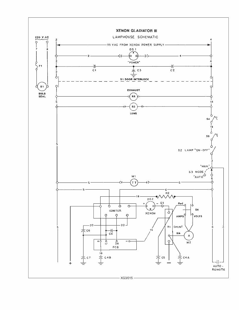
PARTS LISTLamphouse Schematic
Ref.Desig. Part No. Description B1 40905 Bulb Seal Blower Assembly, 220 V.AC, 50/60 Hz. B2 71220 Exhaust Blower, 115 V.AC, 50/60 Hz. B3 47944 Lens Cooling Blower, 115 V.AC, 50/60 Hz. C1,2 76132 Capacitor, .005 µf, 600WVDC * C3 76133 Capacitor, .01 µf, 400 WVDC * C4A, 4B 76323 Capacitor, 10 µf, 370 V. C5 81947 Capacitor, .01 µf, 500 WVDC C6,7 40973 Capacitor, .05 µf, 600 V.DC C8 39956 Capacitor, .05 µf, 1200 V.DC DS1 78984 POWER Indicator Light, 115 V.AC DS2 - Xenon Bulb, 3 kW F1 21-21015 Fuse, 1.5 A. M1 40971 Elapsed Time Meter, 60 Hz. - 40963 Elapsed Time Meter, 50 Hz. M2 40923 Ammeter, 0-150 A. PCB 40913 Igniter Printed Circuit Board Assembly R1 81247 Shunt, 200 A. 50 mV. R2 39886 Resistor, 150k Ohm, ½ Watt S1 80168 Door Interlock Switch S2 81276 LAMP Switch, Rocker Type S3 81276 MODE Switch, Rocker Type S4 39955 Air Flow Switch, Exhaust S5 40936 Air Flow Switch, Intake Blower S6 72275 VOLTAGE Switch, Pushbutton
- 39949A Igniter Assembly, Gladiator - 40904 MS Connector & Interconnect Cable Assembly - 88318 MS Connector, 14 Pin Male
* 40983 RF Suppressor Assembly (C1, C2, C3)
XG3/016
MS CONNECTORA - BLK DC Neg.B - RED DC Pos.C - BRN No. 2D - RED No. 3E - ORN No. 4F - BLU No. 5G - YEL No. 6 I - GRY No. 7J - BLK No. 8M - GRN Ground

PRINCIPLE OF IGNITER OPERATION
THE IGNITER is energized through the 115 V.AC control circuit when the LAMP “ON-OFF”switch (S2) is depressed and all interlocks and air flow switches are closed.
CAUTION: Do not use the Emergency Ignition switch (S102) in the igniter until it is deter-mined that the polarity of the xenon bulb is correct. Use of the S102 switch bypasses the polarity sensing diode(CR201) on the igniter printed circuit board; if polarity is not correct, the bulb will be seriously damaged ordestroyed. No credit is allowed on bulbs damaged by reversed polarity.
THE IGNITER supplies a high RF voltage pulse to the bulb, together with the high “No Load”DC voltage from the xenon power supply, to ignite the xenon bulb. After the arc is sustained, the AC circuit inthe igniter is interrupted by the opening of K201 relay contacts on the signal of the timer circuit on the PC board.The DC output of the xenon power supply is automatically lowered to the power level required to maintain thearc. The DC power to the bulb is dependent upon the bulb characteristics and the setting of the output of thexenon power supply.
DC VOLTAGE is applied to the printed circuit board from the xenon power supply, energizingthe 12 V.DC coil and closing the contacts of K201 relay, completing the AC circuit through the igniter to theT102 high voltage (10 kV.) transformer. High voltage boost capacitor C107 is charged to a voltage sufficient tocause breakdown across the E101 spark gap. Approximately 35 kV. is supplied to the xenon bulb for ignition.
S101 is the igniter cover interlock switch and S102 is the Emergency Ignition switch, which isa bypass for the K201 relay contacts and CR201 polarity sensing diode on the PC board. Components C101,102, and 103 function as RF bypass capacitors on the igniter. The C108 capacitor serves as a coupling capaci-tor to the current coil.
THE PC BOARD operates on DC voltage from the xenon power supply. Capacitor C201across the positive #10 and negative #15 is an RF suppression capacitor. Resistor R201 and zener diodesVR201 and 202 drop the DC voltage to 12 volts for the K201 relay coil. CR201 is the polarity sensing diode.C204 is a polarized capacitor used for arc suppression at the K201 relay coil, and CR202 functions as atransient protection diode.
THE FOLLOWING COMPONENTS are parts of the timing circuit on the PC board: Timerchip U201, resistors R202, 203, and the polarized capacitor C203. The C203 capacitor functions as the timingcontrol, and CR203 serves as the “ON” time control diode. C202 is the control voltage isolation capacitor.
XG3/017

Ref
.D
esig
.Pa
rt N
o.D
escr
iptio
nC
107
3911
0C
apac
itor,
2400
pf,
20 k
V.D
CC
108
3911
0C
apac
itor,
2400
pf,
20 k
V.D
CE1
0139
923
Spar
k G
ap A
ssem
bly
S101
8016
8C
over
Inte
rlock
Sw
itch
S102
8016
8Em
erge
ncy
Igni
te S
witc
hT1
0139
937
Hig
h Vo
ltage
Tra
nsfo
rmer
-
3999
8C
ase
& C
oil,
Potte
d A
ssem
bly
IGN
ITE
R A
SS
EM
BLY
, S
CH
EM
ATIC
XG3/018

Ref
.D
esig
.Pa
rt N
o.D
escr
iptio
nC
201
8826
3C
apac
itor,
.05
µf, 6
00 W
VD
CC
202
7912
7C
apac
itor,
.01
µf, 6
00 W
VD
CC
203
3915
6C
apac
itor,
15 µ
f, 30
/35
WV
DC
C20
488
249
Cap
acito
r, .1
µf,
600
WV
DC
CR
201
8511
2D
iode
, 2.5
A. 1
000
PRV
CR
202
8511
2D
iode
, 2.5
A. 1
000
PRV
CR
203
8511
2D
iode
, 2.5
A. 1
000
PRV
K20
139
154
Rel
ay, P
&B
R10
-E1-
W2S
800
-
3916
0R
elay
Soc
ket
-
3916
1R
elay
Hol
d-D
own
Sprin
gR
201
3915
7R
esis
tor,
1k O
hm, 1
2 W
att
R20
239
158
Res
isto
r, 10
0k O
hm, ½
Wat
t
Ref
.D
esig
.Pa
rt N
o.D
escr
iptio
nR
203
3915
9R
esis
tor,
200k
Ohm
, ½ W
att
U20
172
185
Tim
er IC
, Mot
orol
a M
C11
455P
1
-39
164
IC S
ocke
t, (6
) Pin
VR
201
3921
1Ze
ner D
iode
, 1N
5377
A (4
0913
*)V
R20
181
519
Zene
r Dio
de, 1
N53
61 (4
0984
*)V
R20
239
162
Zene
r Dio
de, 1
N47
42
-39
145
PC B
oard
(les
s C
ompo
nent
s)
*40
913
PCB
Ass
embl
y, S
tand
ard
*
4098
4PC
B A
ssem
bly
(Old
er M
odel
s us
ing
Hig
h R
eact
ance
Pow
er S
uppl
y)
Ass
embl
y N
umbe
r writ
ten
on C
ompo
nent
Sid
e of
PC
B.
IGN
ITE
R P
RIN
TED
CIR
CU
IT B
OA
RD
AS
SE
MB
LY, S
CH
EM
ATIC
XG3/019
W
IRE
MA
RK
ER
SA
= 1
0B
= 1
5C
= 1
7D
= 3
8

XG3/020
TROUBLE CHART
NORMAL OPERATION
WHEN THE SWITCH in the main AC supply line to the xenon power supply is in the ONposition, and the 30 A. circuit breaker on the switching power supply is ON, the POWER lights on the xenonpower supply and the lamphouse instrument panel will glow. The lamphouse blowers will start. The blowersin the power supply will operate.
OPERATION OF THE LAMPHOUSE BLOWERS will close the (2) air flow interlock switches,and if the lamphouse door is closed and correctly secured, the control circuit to the LAMP switch will becompleted.
THE MODE SWITCH, located on the lamphouse instrument panel, should be in the “MAN.”(Manual) position.
WHEN THE LAMP SWITCH is placed in the ON position, the AC control circuit (5 & 6) inthe lamphouse will energize the power supply circuitry providing DC current to the igniter and bulb.
THERE WILL BE a distinctly audible high voltage arc ping at the igniter arc gap and acrossthe bulb electrodes. The bulb should ignite immediately after one or two of these high voltage pulses, and thelamp current will adjust to the output setting of the xenon power supply. Multiple ignition pulses prior to bulbignition normally indicate a low DC output setting. See xenon power supply manual. A “warm” or aged xenonbulb might also require multiple strikes.
TROUBLE SHOOTING
IF THE XENON BULB does not ignite, observe the following operational sequences for assis-tance in locating and isolating the trouble area.
WHEN THE FAN(S) and the indicator light on the power supply are on, the circuit in thepower supply is trouble-free up to the terminal block in the power supply.
AT THIS TIME, the lamphouse blowers should operate. If this does not occur, the trouble isin the door interlock switch, one of the blower motors, a loose connection, a broken #2, #4, #7 or #8 lead, or ablown F1 seal blower fuse. Check the 1.5 A. fuse in the in-line fuseholder. CAUTION: In order to prevent bulbignition when checking the AC control circuit in the lamphouse, remove lead #10 from the igniter terminal strip.
CHECK AT THIS TIME for 115 V.AC Control Voltage at the access door interlock switch(wires 2 & 4), and 220 V.AC at the blower terminals (7 & 8). The door interlock switch must be manuallyactuated to energize the exhuast and lens blowers. Replace #10 lead before proceeding.
THE VANES on the air flow switches should raise. With the MODE switch in the “MAN.”position and the LAMP switch in the “ON” position, the running time meter should start and indicate elapsedtime. If this meter does not operate, check for continuity at the MODE and LAMP switches.
A DEFECTIVE RUNNING TIME METER will not prevent bulb ignition.

XG3/021
WITH THE “LAMP” SWITCH in the “ON” position, a distinct high voltage arc ping shouldbe heard at the spark gap in the igniter, and the flash of the xenon bulb should be visible through the ammeter asa high DC voltage pulse is applied across the bulb electrodes.
IF THE HIGH VOLTAGE PING or the flash at the ammeter is not apparent, check for 115V.AC at terminals 5 & 6 at the terminal board. If 115 V.AC is present, and terminals are tight, check then the“No Load” DC Voltage between the lamphouse and power supply. Remove either lead #5 or #6 at the terminalboard to prevent bulb ignition and defeat the door interlock switch. Check the DC voltage across terminals #10(+) and #15 (-). A reading of 85 V.DC should be measured if using a high reactance power supply; 120-170V.DC if using a switching type. If this voltage is not indicated, the problem is in the leads between the lamp-house and power supply, or in the power supply boost circuit. See the trouble shooting section of the powersupply manual for additional instructions. Replace lead #5 or #6 at the igniter before proceeding.
THE SWITCHING-TYPE XENON POWER SUPPLY furnished with the spotlight systemincludes thermal overload switches and protection circuits to prevent damage resulting from high or low inputvoltage. Loss of DC open circuit voltage, or an interruption of DC sustaining current, may be traced to thesecircuits. See the power supply manual.
IGNITER PRINTED CIRCUIT BOARD 40913 is required for use with the switching typexenon power supply. If the lamphouse is equipped with an older type (40984), replace it with the 40913 board.If the lamphouse ignites only by means of the emergency ignition switch, replace the igniter PC board.
IF THE HIGH VOLTAGE ARC is audible at the lamphouse and the bulb does not flash, checkfor a lamphouse DC lead arcing to ground. If no ground fault is detected, replace the bulb and attempt ignitionwith the new bulb.
IF THE HIGH VOLTAGE ARC is audible at the lamphouse, the flash of the bulb is visible inthe ammeter, but ignition of the bulb is not sustained, the problem area is in the power supply. See the troubleshooting section of the power supply manual for additional instructions.
IF THE HIGH VOLTAGE ARC is not audible or the flash of the bulb visible, the problem is inthe igniter or igniter PC board assembly.
EXCHANGE of components (i.e. igniters, printed circuit boards) between similar StrongXenon Gladiators to aid in diagnosis of a problem is encouraged. This will not lead to equipment damage, andwill not void equipment warranty.

XENON GLADIATOR III TROUBLESHOOTING
Bulb fails to ignite.
1. MODE switch S3 set to “AUTO.” Place in “MAN.” position when not employing automated or remotelamphouse operation.
2. AC power not on to lamphouse. Turn switching power supply 30 A. circuit breaker ON. If 115 V.ACnot read at 2 & 4, or POWER indicator not glowing, see power supply manual.
3. Door interlock switch (S1) open. Close and secure lamphouse door. 4. Faulty interlock switch(s). Check for 115 V.AC at 9 & 12; replace switch(s) if defective. 5. Air vane switches not closing. Check for unobstructed operation; clean if required. Check continuity
between “NO” and “COM;” replace if defective. 6. Faulty S2 “ON-OFF” switch. Check for voltage at 3 & 5; check for loose terminals or wiring. Replace
if defective. 7. Blower fuse F1 blown. Replace as required (1.5 A. Std.). 8. Low AC source voltage actuating “brownout” protection circuit in xenon power supply.
Bulb fails to ignite; ping audible, bulb flash visible.
1. Inadequate DC output from xenon power supply. Set power supply output to correct range required forbulb wattage (95 A. nominal for 3000 watt).
2. If bulb flash is visible but faint, check for defective HV capacitor(s) in igniter. Replace if defective. 3. Faulty or expired xenon bulb. Replace as required.
Bulb fails to ignite; ping audible, no bulb flash.
1. Faulty xenon bulb. Check for cracked electrodes or darkened envelope. Replace if defective. 2. Ignition pulse shorting to ground. Inspect DC leads for burned insulation; dress leads away from
grounded metal components.
No high voltage ping audible; MODE switch in “MAN.” and LAMP switch in “ON.”
1. Loss of AC control voltage. Check xenon power supply for tripped circuit breaker or open thermalswitch. See power supply manual.
2. Little or no DC “No Load” voltage. Measure DC “No Load” voltage at 10 & 15. See power supplymanual.
3. Open fuse F1 (600 V.) on switching power supply. SEE POWER SUPPLY MANUAL. Allow (20)minutes for capacitor discharge before replacing.
4. Faulty igniter printed circuit board. If lamphouse ignites immediately when emergency ignition switchis pressed, replace printed circuit board.
5. Loose spark gap connections or terminals. Repair or replace as required. 7. Faulty igniter. Check for 115 V.AC at 5 & 6; adequate DC “No Load” at 10 & 15. If present, and
igniter does not fire, replace igniter.
XG3/022
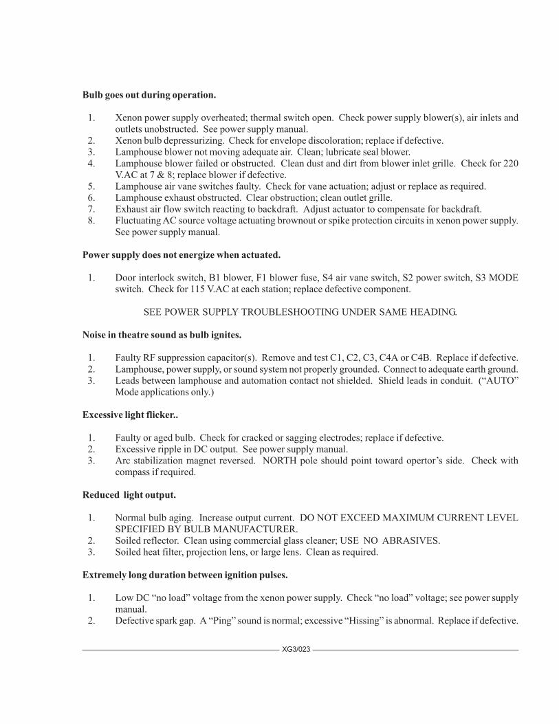
Bulb goes out during operation.
1. Xenon power supply overheated; thermal switch open. Check power supply blower(s), air inlets andoutlets unobstructed. See power supply manual.
2. Xenon bulb depressurizing. Check for envelope discoloration; replace if defective. 3. Lamphouse blower not moving adequate air. Clean; lubricate seal blower. 4. Lamphouse blower failed or obstructed. Clean dust and dirt from blower inlet grille. Check for 220
V.AC at 7 & 8; replace blower if defective. 5. Lamphouse air vane switches faulty. Check for vane actuation; adjust or replace as required. 6. Lamphouse exhaust obstructed. Clear obstruction; clean outlet grille. 7. Exhaust air flow switch reacting to backdraft. Adjust actuator to compensate for backdraft. 8. Fluctuating AC source voltage actuating brownout or spike protection circuits in xenon power supply.
See power supply manual.
Power supply does not energize when actuated.
1. Door interlock switch, B1 blower, F1 blower fuse, S4 air vane switch, S2 power switch, S3 MODEswitch. Check for 115 V.AC at each station; replace defective component.
SEE POWER SUPPLY TROUBLESHOOTING UNDER SAME HEADING.
Noise in theatre sound as bulb ignites.
1. Faulty RF suppression capacitor(s). Remove and test C1, C2, C3, C4A or C4B. Replace if defective. 2. Lamphouse, power supply, or sound system not properly grounded. Connect to adequate earth ground. 3. Leads between lamphouse and automation contact not shielded. Shield leads in conduit. (“AUTO”
Mode applications only.)
Excessive light flicker..
1. Faulty or aged bulb. Check for cracked or sagging electrodes; replace if defective. 2. Excessive ripple in DC output. See power supply manual. 3. Arc stabilization magnet reversed. NORTH pole should point toward opertor’s side. Check with
compass if required.
Reduced light output.
1. Normal bulb aging. Increase output current. DO NOT EXCEED MAXIMUM CURRENT LEVELSPECIFIED BY BULB MANUFACTURER.
2. Soiled reflector. Clean using commercial glass cleaner; USE NO ABRASIVES. 3. Soiled heat filter, projection lens, or large lens. Clean as required.
Extremely long duration between ignition pulses.
1. Low DC “no load” voltage from the xenon power supply. Check “no load” voltage; see power supplymanual.
2. Defective spark gap. A “Ping” sound is normal; excessive “Hissing” is abnormal. Replace if defective.
XG3/023
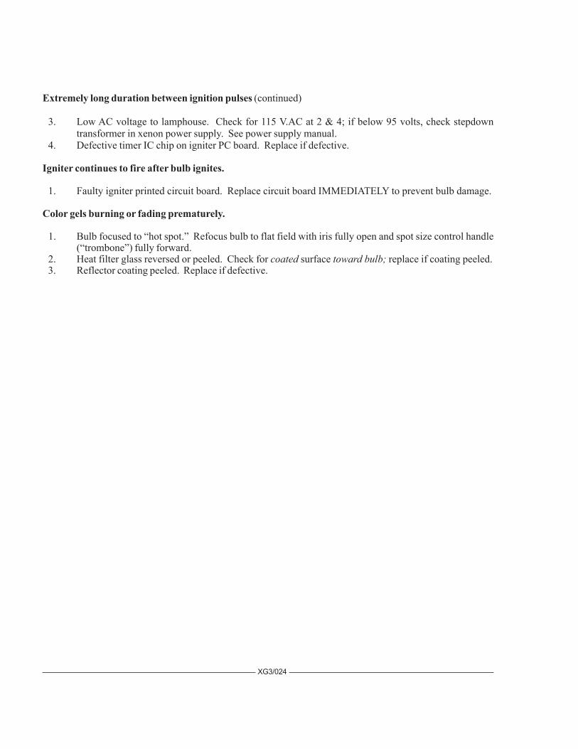
Extremely long duration between ignition pulses (continued)
3. Low AC voltage to lamphouse. Check for 115 V.AC at 2 & 4; if below 95 volts, check stepdowntransformer in xenon power supply. See power supply manual.
4. Defective timer IC chip on igniter PC board. Replace if defective.
Igniter continues to fire after bulb ignites.
1. Faulty igniter printed circuit board. Replace circuit board IMMEDIATELY to prevent bulb damage.
Color gels burning or fading prematurely.
1. Bulb focused to “hot spot.” Refocus bulb to flat field with iris fully open and spot size control handle(“trombone”) fully forward.
2. Heat filter glass reversed or peeled. Check for coated surface toward bulb; replace if coating peeled. 3. Reflector coating peeled. Replace if defective.
XG3/024

FIG
UR
E 1
XG3/025
1 2 3 4 5 67891011
12

PARTS LISTFigure 1
Item Part No. Description 1 40955 Top Cover & Door Welded Assembly - - See 40951 Drawing for Exhaust Assembly - 4100371 Screw, 10-32 x 3/8" Pan Head - 4107001 Lockwasher, #10 2 39139 Magnetic Door Catch (early models*) 3 48930 Arc Viewing Port 4 65353 DANGER Label 5 81282 CAUTION Label - 01639-5 Pop Rivet, 1/8" 6 4100502 Tamperproof Screw, 10-32 x 1/2" Holt Head - 4107101 Flatwasher, #10 - 4108021 Tinnerman Nut, #10 (Clip-On) - 65149A Screwdriver (for 4100502) 7 40100 Name & Data Plate, Super 80 - 01639-2 Pop Rivet, 1/8" 8 40992 Cover Assembly, Bulb Adjust Controls - 40119 Cover Plate 9 65166 Plunger, Black Plastic - 65167 Grommet, Black Plastic 10 40986 Instument Panel Assembly (see Figure 2) 11 39122 Igniter Access Panel - 4080310 Screw, 8-32 x 5/16" Pan Head - 4087004 Lockwasher, #8 12 57275 Plug Button, Emergency Ignite Switch
* See Figure 3, Item 1 for Door Catch (current production)
XG3/026

FIGURE 2
XG3/027
1
2
3
4
5
67
8
9
10
11
12

PARTS LISTFigure 2
Item Part No. Description 1 81276 MODE Switch (S3) 2 81276 LAMP Switch (S2) 3 40102 Plate, Instrument Panel - 4100310 Screw, 10-32 x 5/16" Pan Head 4 65116 Casting, Bulb Adjust Mechanism 5 37985 Thumbscrew - 15010 Compression Spring - 65150 Fender Washer 6 65959 Focus Screw & Bearing Assembly 7 40953 Bulb Support Collet (see Figure 3, Item 14) - 21-48027 Snap Ring, Collet Retaining 8 65153 Thumbscrew, Focus Lock - 65154 Nylon Locking Ball 9 40923 Ammeter (M2) - 71532 Mounting Plate, Ammeter 10 40971 Elapsed Time Meter (M1), 60 Hz. - 40963 Elapsed Time Meter, 50 Hz. (Export) 11 78984 POWER Indicator Light (DS1), 115 V.AC 12 72275 Switch (S5), Voltage Test - 39886 Resistor (R2) - 72276 Button, Plastic
XG3/028

FIG
UR
E 3
1 2 3 4 5
67
89
1011
1213141516
XG3/029

XG3/030
PARTS LISTFigure 3
Item Part No. Description 1 40955 Door & Top Cover Welded Assembly - 4100503 Screw, 10-32 x 1/2" Pan Head - 4107001 Lockwasher, #10 - 40174 Upper Bracket, Door Catch - 40175 Door Catch Plate, Slotted - 40176 Lower Bracket, Door Catch - 40173 Stud, Door Catch Plate 2 48930 Arc Viewing Port 3 40958 Front Casting, Gladiator III - 40958 does not include snood & douser (as illustrated) 4 - Douser Assembly not used 5 - on Gladiator Lamphouse 6 4108021 Tinnerman (Clip-On) Nut, #10 7 40985 Lamphouse Base Pan 8 40987 Binding Post Assembly (E1) - 40130 Phenolic Block - 4371500 Contact Screw, 3/8-16 x 1-1/2" Flat Head - 40131 Fibre Insulator - 4378006 Jam Nut, 3/8-16 Hex - 4377100 Flatwasher, 3/8" Brass - 4250750 Mounting Screw, 1/4-20 x 3/4" Flat Head - 4258001 Hexnut, 1/4-20 9 40107 Air Duct Casting - 4310750 Mounting Screw, 5/16-18 x 3/4" Hex Head, Nylon - 40116 Fibre Insulator - 40900 Bulb Support Yoke - 00781 Yoke Set Screw, 8-32 x 1/4" 10 40104 Reflector Bulkhead Casting - 40142 Tie Rod, 1/4-20 - 4258001 Lock Nut, 1/4-20 Hex 11 40120 Dust Cover - 4080250 Screw, 8-32 x 1/4" Pan Head - 4087004 Lockwasher, #8 12 M15315 Arc Stabilizer Magnet - 81137 Magnet Clamp - 4080259 Set Screw, 8-32 x 1/4" - 4080251 Clamp Mounting Screw, 8-32 x 1/4" Hex Head

XG3/031
Item Part No. Description 13 23754 Flanged Reflector, 15" Dichroic - 4250505 Mounting Screw, 1/4-20 x 1/2" Socket Head - 4257102 Flatwasher, 1/4" 14 40953 Rear Bulb Support Collet - 21-48027 Retaining Ring - 40944 Igniter Lead & Clamp Assembly - 40114 Clamp - 4080870 Clamping Screw, 8-32 x 7/8" Socket Head - 4250373 Lead Mounting Screw, 1/4-20 x 3/8" Hex Head 15 39949A Igniter Assembly (see Figure 5) 16 40105 Rear Casting
NOT SHOWN
71284 Cam Lock & Key, Lamphouse Access Door25372 Cam Lock Security Screw, Special Hex Head
PARTS LIST, Figure 3 (continued)

FIGURE 4
XG3/032
1
2
3
4
5
67891011
12
13
14
15
16
17
18
19

Item Part No. Description 1 40905 Bulb Seal Blower Assembly (B1), 220 V.AC, 50/60 Hz. - 40993 Blower Inlet Grille - 4080375 Screw, 8-32 x 3/8" Pan Head - 4087004 Lockwasher, #8 2 40136 Capacitor Clamp - 4080181 Clamp Mounting Screw, 8-32 x 3/16" Pan Head - 4087004 Lockwasher, #8 3 76323 Capacitor (C4A & C4B) 4 40981 Cable Assembly, Shunt to Binding Post 5 40983 RF Suppression Capacitor Assembly (C1,2,3) - 39153 PCB Stand-Off, Nylon 6 76133 Capacitor (C3) 7 76132 Capacitor (C1, C2) 8 40913 Igniter Printed Circuit Board Assembly - 40984 Igniter PC Board (with High Reactance power supply) - 39154 Relay, PC Board (K201) - 39153 PCB Stand-Off, Nylon 9 40974 Capacitor (C8) 10 40103 Barrier Strip, (14) Terminal - 40138 Insulated Marker Strip - 4080627 Screw, 8-32 x 5/8" Fillister Head - 4087004 Lockwasher, #8 11 80168 Door Interlock Switch (S1) - 39321 Switch Bracket, Recessed - 4060501 Screw, 6-32 x 1/2" Flat Head - 4068001 Hexnut, 6-32 12 81247 Shunt (R1), 200 A. 50 mV. - 4080506 Screw, 8-32 x 1/2" Pan Head - 4087004 Lockwasher, #8 13 40973 RF Bypass Capacitor Assembly (C6, C7) 14 40961 Fuse Wire Assembly - 39199 Fuse Holder - 21-21015 Fuse (F1), 1.5 A 15 81274 Ground Lug 16 40904 Lamphouse/Power Supply Interconnect Cable Assembly - 81143 Cable Connector, 90° Elbow 17 40953 Rear Bulb Support Collet - 40944 Igniter Lead & Clamp Assembly 18 39955 Air Flow Switch (S4) - 00953 Screw, 4-40 x 1/2" Round Head 19 40164 Light Baffle & Wiring Channel - 4110311 Screw, 10-24 x 5/16" Pan Head
PARTS LISTFigure 4
XG3/033

1 2 3 4 5 6
78910
FIG
UR
E 5
IGNITER ASSEMBLY
XG3/034

Item Part No. Description 1 80168 Cover Interlock Switch (S101) 2 39113 Switch Bracket - 4100251 Screw, 10-32 x 1/4" Flat Head 3 80168 Emergency Ignite Switch (S102) 4 39110 High Voltage Capacitor (C107, 108) - 4080252 Screw, 8-32 x 1/4" Socket Head - 4087004 Lockwasher, #8 - 39112 Capacitor Mounting Plate - 4251001 Screw, 1/4-20 x 1" Hex Head Nylon - 4258015 Hex Nut, 1/4-20 Nylon 5 4080250 Screw, 8-32 x 1/4" Pan Head - 4087004 Lockwasher, #8 6 39998 Case & Current Coil, Potted Assembly - 65353 DANGER Label 7 39201 * Spark Gap Body, Nylon - 4110501 Screw, 10-24 x 1/2" Pan Head 8 39107 * Contact Screw, Tungsten - 39109 Terminal Tab - 4107100 Flatwasher, #10 Brass - 4088001 Hexnut, 8-32 * 39923 Spark Gap Assembly (Items 7 & 8, Gapped) 9 39937 High Voltage Transformer (T102) - 4087101 Flatwasher, #8 - 4088001 Hexnut, 8-32 10 39204 Transformer Spacer
NOT SHOWN
39101 Igniter Box Cover, Black Plastic4060250 Cover Mounting Screw, 6-32 x 1/4" Pan Head
PARTS LISTFigure 5
XG3/035
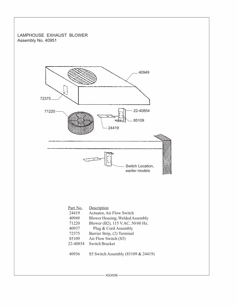
LAMPHOUSE EXHAUST BLOWERAssembly No. 40951
Part No. Description 24419 Actuator, Air Flow Switch 40949 Blower Housing, Welded Assembly 71220 Blower (B2), 115 V.AC, 50/60 Hz. 40937 Plug & Cord Assembly 72375 Barrier Strip, (2) Terminal 85109 Air Flow Switch (S5)22-40854 Switch Bracket
40936 S5 Switch Assembly (85109 & 24419)
XG3/036
72375
71220
24419
85109
22-40854
40949
Switch Location,earlier models

FIGURE 6
XG3/037

Item Part No. Description 1 49943 Lifting Strap 2 4377102 Flatwasher, 3/8" 3 49120 Tilt Axis Bolt 4 4378002 Locknut, 3/8-16 Hex 5 02411 Washer, .640" I.D. x 1-1/4" O.D. 6 72-01021 Clamp Plate 7 49125 Compression Spring, Tilt Clamp 8 49124 Spring Bushing 9 49223 Clamp Shaft 10 49130 Clamp Handle 11 10048A Knob, Round Plastic 12 49290 Swivel Clamp Shaft - 49291 Stop Plate, Horizontal Swivel - 4872500 Bolt, 3/8-16 x 2-1/2" Square Head 13 49130 Clamp Handle 14 83799 Base Column, Welded Assembly 15 83297 Mounting Bolt, Base Leg - 4377001 Lockwasher, 3/8" Split Ring 16 83797 Base Leg, Welded Assembly - 11-09013 Caster, Locking (not shown) 17 49226 Leveling Foot - 4508001 Locknut, 1/2-13 Hex 18 83294A Height Adjustment Pin - 21-71187 Lanyard (Wire Rope, 9 inches req’d.) - 11-98230 Lanyard Clamp (2 req’d.) - 4100376 Lanyard Mounting Screw, 10-3/8" Self-Tap 19 83794 Tube & Collar Assembly 20 83113 Needle Bearing 21 83114 Race, Needle Bearing 22 49213 Swivel Clamp Collar - 4250503 Screw, 1/4-20 x 1/2" Hex Head - 4257000 Lockwasher, 1/4" Split Ring 23 83357 Yoke Cover Plate - 4080375 Screw, 8-32 x 3/8" Pan Head - 4087004 Lockwasher, #8 24 83112 Collar, Inner Tube - 4260370 Set Screw, 1/4-28 x 3/8" Dog Point 25 47951 Yoke Assembly 26 4371120 Screw, 3/8-16 x 1" - 4377001 Lockwasher, 3/8" - 4377103 Flatwasher, 3/8" - 4378001 Hexnut, 3/8-16 27 47958 Saddle & Quadrant Assembly 28 83341 Cable Clamp - 4250623 Screw, 1/4-20 x 5/8" Hex Head
PARTS LISTFigure 6
XG3/038

FIG
UR
E 7
XG3/039

Item Part No. Description 1 49342 Hand Rail - 4317000 Lockwasher, 5/16" Split Ring - 4310500 Screw, 5/16-18 x 1/2" Hex Head 2 47944 Blower Assembly (B3), with Item 5 - 44191 Blower Motor & Squirrelcage, 115 V.AC - 21-40011 Plug, (2) Pin Male - 31-62007 Molex Pin, Male - 21-40019 Receptacle, (2) Pin Female - 31-62006 Molex Pin, Female 3 4080375 Screw, 8-32 x 3/8" Pan Head (as req’d.) 4 47177 Receptacle Bracket (not req’d. in current units) 5 21-71066 Cable, 18/2 Type SJ (incl. with Item 2) 6 47945 Base Rail, Welded Assembly
NOT SHOWN
47989 Front Counterweight47988 Counterweight Bracket4310500 Screw, 5/16-18 x 1/2" Hex Head4317000 Lockwasher, 5/16" Split Ring4317100 Flatwasher, 5/16"4250505 Screw, 1/4-20 x 1/2" Hex Head4257000 Lockwasher, 1/4" Split Ring4257100 Flatwasher, 1/4"
PARTS LISTFigure 7
XG3/040

FIG
UR
E 8
XG3/041
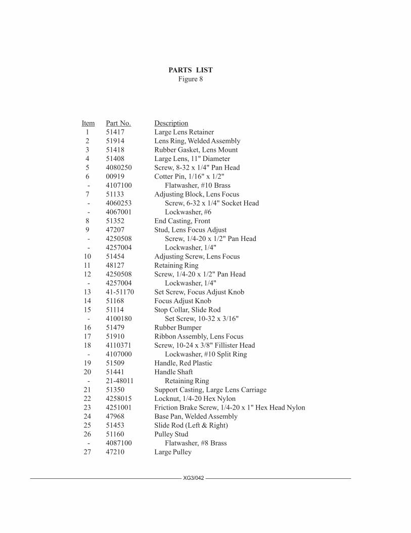
Item Part No. Description 1 51417 Large Lens Retainer 2 51914 Lens Ring, Welded Assembly 3 51418 Rubber Gasket, Lens Mount 4 51408 Large Lens, 11" Diameter 5 4080250 Screw, 8-32 x 1/4" Pan Head 6 00919 Cotter Pin, 1/16" x 1/2" - 4107100 Flatwasher, #10 Brass 7 51133 Adjusting Block, Lens Focus - 4060253 Screw, 6-32 x 1/4" Socket Head - 4067001 Lockwasher, #6 8 51352 End Casting, Front 9 47207 Stud, Lens Focus Adjust - 4250508 Screw, 1/4-20 x 1/2" Pan Head - 4257004 Lockwasher, 1/4" 10 51454 Adjusting Screw, Lens Focus 11 48127 Retaining Ring 12 4250508 Screw, 1/4-20 x 1/2" Pan Head - 4257004 Lockwasher, 1/4" 13 41-51170 Set Screw, Focus Adjust Knob 14 51168 Focus Adjust Knob 15 51114 Stop Collar, Slide Rod - 4100180 Set Screw, 10-32 x 3/16" 16 51479 Rubber Bumper 17 51910 Ribbon Assembly, Lens Focus 18 4110371 Screw, 10-24 x 3/8" Fillister Head - 4107000 Lockwasher, #10 Split Ring 19 51509 Handle, Red Plastic 20 51441 Handle Shaft - 21-48011 Retaining Ring 21 51350 Support Casting, Large Lens Carriage 22 4258015 Locknut, 1/4-20 Hex Nylon 23 4251001 Friction Brake Screw, 1/4-20 x 1" Hex Head Nylon 24 47968 Base Pan, Welded Assembly 25 51453 Slide Rod (Left & Right) 26 51160 Pulley Stud - 4087100 Flatwasher, #8 Brass 27 47210 Large Pulley
PARTS LISTFigure 8
XG3/042
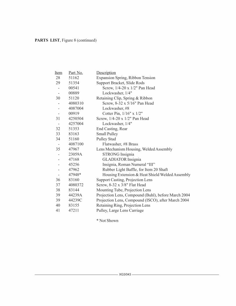
Item Part No. Description 28 51162 Expansion Spring, Ribbon Tension 29 51354 Support Bracket, Slide Rods - 00541 Screw, 1/4-20 x 1/2" Pan Head - 00889 Lockwasher, 1/4" 30 51120 Retaining Clip, Spring & Ribbon - 4080310 Screw, 8-32 x 5/16" Pan Head - 4087004 Lockwasher, #8 - 00919 Cotter Pin, 1/16" x 1/2" 31 4250504 Screw, 1/4-20 x 1/2" Pan Head - 4257004 Lockwasher, 1/4" 32 51353 End Casting, Rear 33 83163 Small Pulley 34 51160 Pulley Stud - 4087100 Flatwasher, #8 Brass 35 47967 Lens Mechanism Housing, Welded Assembly - 23059A STRONG Insignia - 47168 GLADIATOR Insignia - 45256 Insignia, Roman Numeral “III” - 47962 Rubber Light Baffle, for Item 20 Shaft - 47948* Housing Extension & Heat Shield Welded Assembly 36 83160 Support Casting, Projection Lens 37 4080372 Screw, 8-32 x 3/8" Flat Head 38 83144 Mounting Tube, Projection Lens 39 44239A Projection Lens, Compound (Buhl), before March 2004 39 44239C Projection Lens, Compound (ISCO), after March 2004 40 83155 Retaining Ring, Projection Lens 41 47211 Pulley, Large Lens Carriage
* Not Shown
PARTS LIST, Figure 8 (continued)
XG3/043

58
59 FI
GU
RE
9
Ite
m 5
8 B
rack
et
mo
un
ts t
ob
ack
su
rfa
ce
of
Ite
m 3
1.
XG3/044

Item Part No. Description 1 10048A Knob, Red Plastic 2 51451 Iris Shaft 3 406037B Screw, 6-32 x 3/8" Pan Head 4 4067001 Lockwasher, #6 5 51978 Friction Spring & Button - 51229 Friction Pad 6 4060621 Screw, 6-32 x 5/8" Socket Head 7 4067001 Lockwasher, #6 8 51979 Iris (as shown; see Fig. 9A for current configuration) - 83181 Plate, 51979 Iris - 83182 Retaining Clip, 51979 Iris 9 51226 Pivot Stud 10 83773 Aperture Support Plate 11 51160 Pulley Stud 12 83163 Large Pulley 13 4087100 Flatwasher, #8 Brass 14 47191 Masking Blade 15 47982 Slide Assembly, Masking Blade 16 4087000 Lockwasher, #8 Split Ring 17 4080375 Screw, 8-32 x 3/16" Pan Head 18 4257102 Flatwasher, 1/4" 19 51156 Friction Plate (Replace with 4507106 Friction Washer) 20 83134 Fadeout Pull Rod, Long 21 4257000 Lockwasher, 1/4" Split Ring 22 4258001 Hexnut, 1/4-20 23 4107100 Flatwasher, #10 Brass 24 4107001 Lockwasher, #10 25 4080250 Screw, 10-32 x 1/4" Pan Head 26 4080250 Screw, 10-32 x 1/4" Pan Head 27 4107001 Lockwasher, #10 28 4107100 Flatwasher, #10 Brass 29 83351 Retaining Strip, Fadeout Bracket 30 51226 Pivot Stud 31 83890 Fadeout Support Assembly 32 83892 Fadeout Blade, Lower 33 83891 Fadeout Blade, Upper 34 51153 Spacer Bushing
PARTS LISTFigure 9
XG3/045

Item Part No. Description 35 83133 Fadeout Pull Rod, Short 36 01704 Spring Pin 37 51357 Cover Plate Casting 38 4250508 Screw, 1/4-20 x 1/2" Pan Head 39 10048A Knob, Red Plastic 40 51155 Control Lever, Fadeout Mechanism 41 83143 Fadeout Lever Bracket 42 10048A Knob, Red Plastic 43 51452 Control Lever, Masking Blades 44 51498 Masking Blade Pull Rod, Short 45 51156 Friction Plate (Replace with 4507106 Friction Washer) 46 4317100 Flatwasher, 5/16" 47 4318004 Hexnut, 5/16-18 FlexLock 48 MAL-64 Spacer (early models only) 49 4257000 Lockwasher, 1/4" Split Ring - 4257102 Flatwasher, 1/4" 50 4258001 Hexnut, 1/4-20 51 4318004 Hexnut, 5/16-18 FlexLock 52 48406 Bracket, Masking Blade Control Lever 53 51153 Spacer Bushing 54 51497 Masking Blade Pull Rod, Long 55 47170 Stop Bracket, Iris Lever 56 4087004 Lockwasher, #8 Split Ring 57 4080250 Screw, 8-32 x 1/4" Pan Head 58 47966 Mounting Bracket, Heat Filter Glass - 4100371 Mounting Screw, 10-32 x 3/8" Pan Head - 4107104 Lockwasher, #10 59 65122A Heat Filter Glass, Coated
ASSEMBLIES
83788 Aperture Plate, Masking Blades, and Iris(Items 1-17, 42-50, & 52-57)
83790 Fadeout Mechanism and Blades(Items 18-36, 39-41, & 51)
PARTS LIST, Figure 9 (continued)
XG3/046

XG3/047
51451
4060372
41-51530,25017
21-70029
406037224369
24374
72-00075
4080621
25034
FIGURE 9A
24372
Part No. Description21-70029 Spring Washer24369 Bell Crank24372 Adapter Ring24374 Iris25017 Bushing (with 41-51530)25034 Iris Clamp4040310 Screw, 4-40 x 5/16"4060372 Screw, 6-32 x 3/8"4080621 Screw, 8-32 x 5/8"41-51530 Shoulder Bolt51451 Iris Control Handle72-00075 Link81432 Shoulder Screw
4040310
81432
83773ref. Figure 9,Item 10

FIG
UR
E 1
0
47
XG3/048

Item Part No. Description 1 51376 Cover Plate, Gel Frame 2 51928 Gel Frame & Slide Channel 3 01456 Paper Fastener 4 4068001 Hexnut, 6-32 5 4067001 Lockwasher, #6 6 51926 Plate & Slide Channel, Ultra Violet 7 51192 Ultra Violet Lens 8 51406 Clip, UV Lens 9 406037B Screw, 6-32 x 3/8" Pan Head 10 4088001 Hexnut, 8-32 11 4087000 Lockwasher, #8 Split Ring 12 51404 Support Arm 13 51396 Catch, Color Arm 14 4080754 Screw, 8-32 x 1/2" Pan Head 15 51379 Mounting Bracket, Right 16 4107000 Lockwasher, #10 Split Ring 17 4110501 Screw, 10-24 x 1/2" Round Head 18 51398 Nylon Washer 19 51402 Torsion Spring, UV Filter 20 51927 UV Arm Assembly 21 408037A Screw, 8-32 x 5/16" Fillister Head - 4087000 Lockwasher, #8 Split Ring 22 51465 Torsion Spring, Color Arm 23 51929 Color Arm Assembly, 6-11/16" 24 51403 Pivot Shaft, Color Arms 25 00919 Cotter Pin, 1/16" x 1/2" 26 4107101 Flatwasher, #10 S.A.E. 27 51922 Rocker Catch Assembly, Short - 51506 Rubber Pad, Short 28 17219 Compression Spring, Release Button 29 51923 Rocker Catch Assembly, Long - 51505 Rubber Pad, Long 30 90473 Compression Spring, Release Button 31 00919 Cotter Pin, 1/16" x 1/2" 32 51467 Washer, Color Release Button 33 51397 Color Release Button 34 51395 Rocker Catch Shaft
PARTS LISTFigure 10
XG3/049

Item Part No. Description 35 01475 Cotter Pin, 1/16" x 3/8" 36 51356 Cover, Boomerang Housing - 4080506 Screw, 8-32 x 1/2" Pan Head 37 51166 Retaining Screw, Boomerang Cover 38 51930 Color Arm Assembly, 6-3/16" 39 51931 Color Arm Assembly, 5-11/16" 40 51932 Color Arm Assembly, 5-3/16" 41 51933 Color Arm Assembly, 4-11/16" 42 51934 Color Arm Assembly, 4-3/16" 43 51378 Mounting Bracket, Left 44 51399 Spacer 45 51400 Stop Shaft 46 51401 Rubber Stop 47 19893 Boomerang Heat Filter Assembly - 47231 Bracket - 47232 Heat Filter Mounting Disc - 47233 Heat Filter - 46150 Assembly Clip
PARTS NOT SHOWN
51913 Boomerang Housing & Hinge51471 Rubber Bumper Pad, 7" x 8"01304 Screw, 8-32 x 5/16" Pan Head4088001 Hexnut, 8-324087004 Lockwasher, #851355 Boomerang Housing Support Casting, Rear4080372 Screw, 8-32 x 3/8" Flat Head51864 Auxiliary Color Holder (replaces UV Filter)
PARTS LIST, Figure 10 (continued)
NOTE: Color temperature reduction filters, required for use with television and videotape, are available fromtheatrical supply dealers.
XG3/050