Xbee Wireless Uploading and Communicationthesis.ruedamanuel.com/complements/xbeeTutorial.pdf · In...
31
Xbee Wireless Uploading and Communication Manuel Rueda Iragorri
Transcript of Xbee Wireless Uploading and Communicationthesis.ruedamanuel.com/complements/xbeeTutorial.pdf · In...

Xbee Wireless Uploading and Communication
Manuel Rueda Iragorri
Abstract
In this tutorial you will learn how to use xbee modules to wirelessly upload programs to an Arduino Pro board and be able to communicate from one point to another through serial. The hardware used is readily available on the web and there's an Arduino program provided for testing.

Parts● Sparkfun
● XBee Explorer Regulated.– http://www.sparkfun.com/commerce/product_info.php?products_id=9132
● Arduino Pro Board.– http://www.sparkfun.com/commerce/product_info.php?products_id=9219
● FTDI Basic Breakout 5V.– http://www.sparkfun.com/commerce/product_info.php?products_id=9115
● Adafruit● USB XBee adapter.
– http://www.adafruit.com/index.php?main_page=product_info&cPath=29&products_id=247&zenid=1d827de14d0a4efa6c740ad1c9eefc3b
● XBee adapter kit.– http://www.adafruit.com/index.php?
main_page=product_info&cPath=29&products_id=126&zenid=1d827de14d0a4efa6c740ad1c9eefc3b
● 4 XBee Series 1 modules.– http://www.adafruit.com/index.php?
main_page=product_info&cPath=29&products_id=128&zenid=1d827de14d0a4efa6c740ad1c9eefc3b
You will also need male and female header pins, a soldering iron, solder, a blank PCB, a 9V battery clip and 22 gauge wire but you should be able to find all of the above somewhere around where you live.

Software
● Arduino● www.arduino.cc
● New Soft Serial Library for Arduino● http://arduiniana.org/libraries/NewSoftSerial/
● XCTU● http://www.digi.com/support/kbase/kbaseresultdetl.jsp?kb=125
FOR MAC USERS● Parallels
● http://www.parallels.com/
● Windows 7

Step 1 – Assemble your kits
Some of the Sparkfun parts (the FTDI breakout and the Arduino Pro board) come pre-assembled. However, the XBee explorer regulated and the Adafruit parts need some assembly. The assembly is as follows:
XBee explorer regulated:
1. Get your female header pins and cut a line of 6.
2. If you have 90º headers, you should use them, if not, bend the short end of your headers with some pliers.
3. Place the headers on the regulated explorer as shown in the picture.
4. Solder the headers in place and you're done with this part.
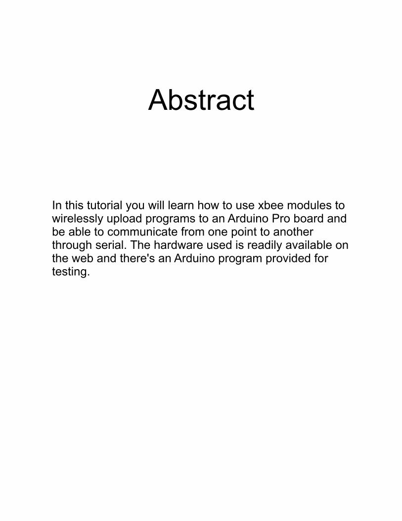
USB XBee Adapter
1. Take the PCB from the bag, you will be soldering the other parts to it.
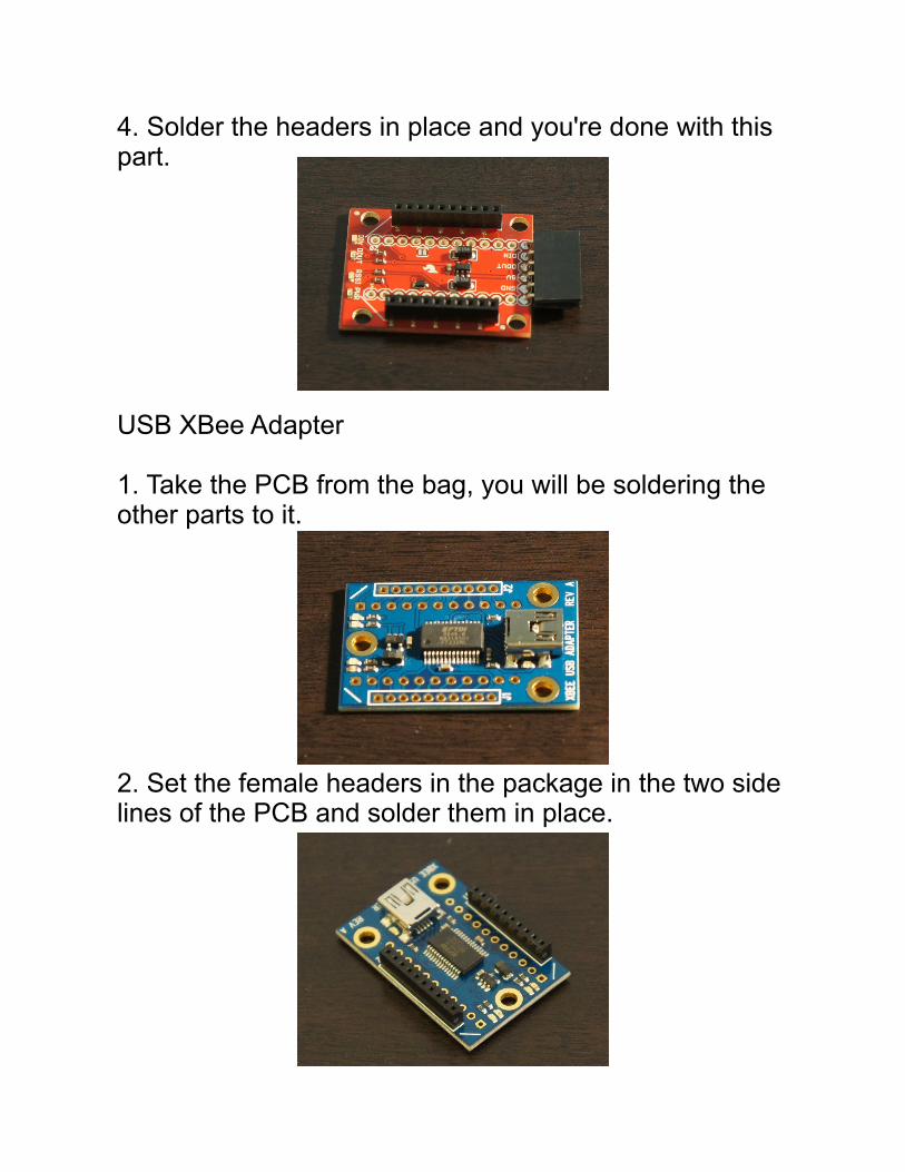
2. Set the female headers in the package in the two side lines of the PCB and solder them in place.

4. Flip the PCB and solder the male headers in the package on the lines that are closer to the center as shown in the picture.
5. Flip the PCB again and place an XBee module on the female headers to make sire it fits.
6. Cut a strip of two female headers (from the ones you bout separately) and solder their male ends together to create a jumper.
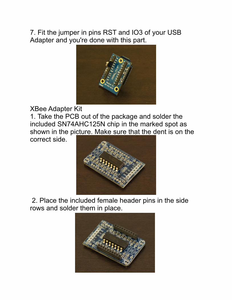
7. Fit the jumper in pins RST and IO3 of your USB Adapter and you're done with this part.
XBee Adapter Kit1. Take the PCB out of the package and solder the included SN74AHC125N chip in the marked spot as shown in the picture. Make sure that the dent is on the correct side.
2. Place the included female header pins in the side rows and solder them in place.

3. Solder the red and green LEDs on the PCB as shown in the picture. They are polarized, so make sure that the long leg in the LED aligns with the + sign in the PCB.
4. Solder the electrolytic capacitor in C2. Again, the long leg should line up with the + sign on the board.
5. Place the included transistor opposite to the capacitor you just attached and solder it in place. Make sure the flat part faces in.

6. Place and solder the ceramic capacitor in C1. This one isn't polarized so it doesn't matter in which direction you solder it.
7. Solder the 10K resistor (brown, black, orange) on the R3 spot. In resistors, direction doesn't matter.
8. Now place and solder the remaining 1K resistors (brown, black, red).

9. Carefully solder the provided header pins from the output terminals facing out as seen in the picture.
10. Place an XBee module on the female headers and you're done with this part.

Step 2 – Make a Custom Shield
Test your Arduino Pro:
1. Grab your Arduino Pro board, the FTDI adapter and a USB to USB B cable.
2. Plug it to your computer as shown in the following picture.

3. Open Arduino, open the blink example and upload it to your board. Make sure you select the correct USB port and the correct board in the tools menu.
4. Upload the blink program to your board to make sure it is working properly. If it doesn't, check the troubleshooting section in the Arduino site for information on how to solve the problem.
Modify your Board
1. Cut a strip of two female header pins and solder them to the power input slots on the Arduino Pro.
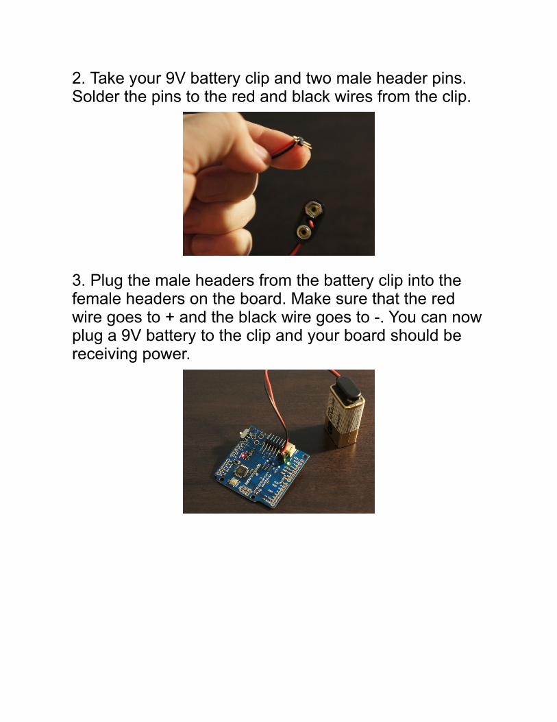
2. Take your 9V battery clip and two male header pins. Solder the pins to the red and black wires from the clip.
3. Plug the male headers from the battery clip into the female headers on the board. Make sure that the red wire goes to + and the black wire goes to -. You can now plug a 9V battery to the clip and your board should be receiving power.
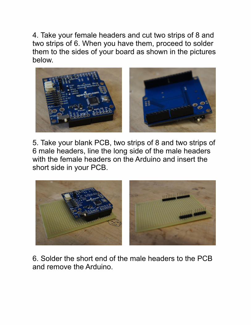
4. Take your female headers and cut two strips of 8 and two strips of 6. When you have them, proceed to solder them to the sides of your board as shown in the pictures below.
5. Take your blank PCB, two strips of 8 and two strips of 6 male headers, line the long side of the male headers with the female headers on the Arduino and insert the short side in your PCB.
6. Solder the short end of the male headers to the PCB and remove the Arduino.
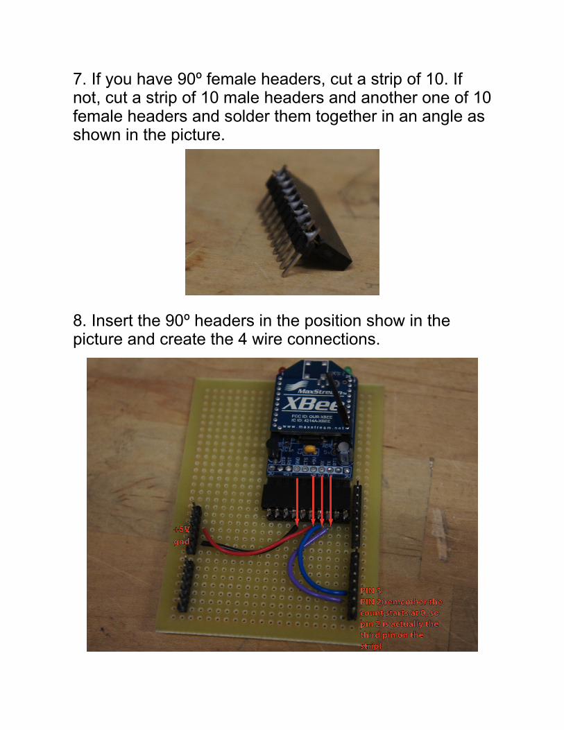
7. If you have 90º female headers, cut a strip of 10. If not, cut a strip of 10 male headers and another one of 10 female headers and solder them together in an angle as shown in the picture.
8. Insert the 90º headers in the position show in the picture and create the 4 wire connections.

9. When you've finished making the connections, plug your XBee adapter in the newly made 10 pin connector (as shown in the previous instruction) and then plug the shield to the Arduino.
10. Plug the female headers from the regulated XBee explorer into the male headers on the Arduino as shown below.

11. Plug the 9V battery to the Arduino as shown before and you should now be seeing the LED's in every one of your boards turn on.

Step 3 – Configure your XBees
Updating the Firmware(Necessary for all of your modules)
1. If you have windows, don't mind this first step. If you are a Mac user, install Windows in your machine and use it through Parallels. Each one of the aforementioned programs has its own instructions in it's software bundle.
2. Once you're set and have windows running, plug your USB XBee adapter to your computer. If you're running Parallels, you'll have make sure to select “virtual machine” from the “connect the USB device to:” menu that should pop up automatically. If your computer gives you an error, it's probably because you haven't installed the drivers for the FTDI chip you are using. You can go to this site http://www.ftdichip.com/FTDrivers.htm and download the drivers for free.

3. Open XCTU and you should see a window like this:
4. Press the “test/query” button to make sure you have a working connection with your XBee module. If you do, you should see a pop up window saying what kind of module you have (there are multiple kinds of XBee modules) and what firmware are you running.

5. Click on the module configuration tab and then click “read”.
6. If this is the first time you do it, you will probably have to go download the latest firmware updates. To do so, you can allow the program to look for updates online or, if you are on a virtual machine with no connection to the internet, you can download the firmware from this site http://www.digi.com/support/kbase/kbaseresultdetl.jsp?id=2182 and copy the files to your virtual machine. Click on “download new versions” and pick the choice that better suits you.
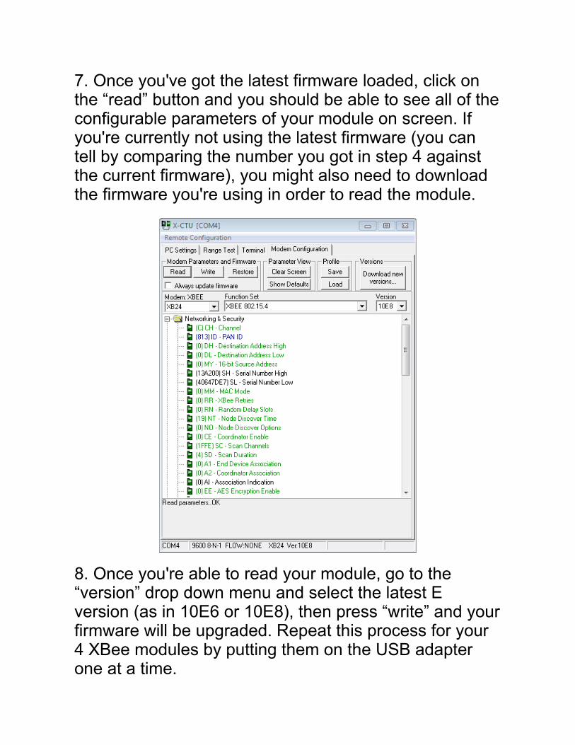
7. Once you've got the latest firmware loaded, click on the “read” button and you should be able to see all of the configurable parameters of your module on screen. If you're currently not using the latest firmware (you can tell by comparing the number you got in step 4 against the current firmware), you might also need to download the firmware you're using in order to read the module.
8. Once you're able to read your module, go to the “version” drop down menu and select the latest E version (as in 10E6 or 10E8), then press “write” and your firmware will be upgraded. Repeat this process for your 4 XBee modules by putting them on the USB adapter one at a time.

Configuring the Serial Com modules
1. XBee modules can talk to multiple other modules, but they need to have the same baud rate and the same PAN ID. An XBee module can have a PAN ID ranging from 0000 to FFFF so that it doesn't interfere with other modules' info transfer. In this case, since we're going to use two modules to send and receive instructions actively through serial and two modules for wireless program uploading, we want each pair to be on a different network. To do so, click on the ID – PAN ID line on the Networking and Security folder and set a unique number for your serial network, in this case I chose 813.
Since you just upgraded the firmware, the baud rate should be at 9600 so just click on “write” and repeat the process for the other module in this network. You can now set one of the two modules in the XBee adapter on your shield.

Configuring the Wireless Uploading Modules
1. Now that you have the Serial Com modules done, put one of the wireless uploading modules on the USB adapter and click “read”. This is going to be your sender module.2. After you read your module change your PAN ID to a number different to the one you used before. In this case, I chose 624.
3. Scroll down to the Serial Interfacing folder and change the BD - Interface Data Rate to 57600. 4. Go a couple of lines down and change the RO – Packetization Timeout to 10, so that there's enough time to send the program through.

5. Scroll down to the I/O Settings folder and go to D3 - DIO3 Configuration. Change the preset for DI, which stands for digital input.6. Move a few lines down to DIO Change Detect and change the preset to FF so that all changes are accounted for.7. Click on the “write” button and you will be done with the sender module for the wireless uploading.
If you try to read the module again, it will not work because you have the interface of XCTU running at a baud rate of 9600. To access the module you just wrote in, go to the PC Settings tab in XCTU and change the baud rate to 57600.

8. Now that you're done with the sender, lets focus on the receiver. Change the module on your USB adapter and read it (make sure you're at a baud rate of 9600 to read the last module).9. Repeat instructions 2 to 4 for this module (set PAN ID, baud rate 57600 and packetization timeout 10).10. Scroll down to D3 – DIO3 Configuration in the I/O Settings folder and change the preset to DO HIGH, which stands for a digital output that's naturally pulled up.
11. Move a few lines down and select IU – I/O Output Enable and disable it so that there's no info sent to the serial line when the program is being uploaded.

12. Open the I/O Line Passing folder and select IA – I/O Input Address.13. Click on Set and write FFFF on the text field, then click ok.
14. Now click the “write” button and your receiver is all set. You can take it off the USB adapter and put it back in the XBee regulated explorer.

Step 4 – Use the System
Set it Up
1. Reassemble the whole shield. Make sure that the receiver module goes on the regulated XBee Explorer, one of the Serial Com modules goes in the XBee adapter and the sender module goes in the USB XBee adapter (you should have one serial com module left).
2. Open Arduino (I did it from the virtual machine but it should work in both) and copy the following program:

/*Test program for arduino wireless uploading and control through XBee.If you press H, the built in led should turn high, if you press L it should turn low.
by Manuel Rueda Iragorri */
#include <NewSoftSerial.h>
NewSoftSerial mySerial = NewSoftSerial(2, 3);//don't change these numbers
int led=13;char inByte=0;
void setup(){
pinMode (led,OUTPUT); Serial.begin(9600); //both have to be set at the same baud rate mySerial.begin(9600); Serial.println("Program Started");
}void loop(){
if (mySerial.available()){ inByte=mySerial.read(); } if ((inByte=='H')||(inByte=='h')){ digitalWrite(led,HIGH); Serial.print("H"); } else if((inByte=='L')||(inByte=='l')){ digitalWrite(led,LOW); Serial.print("L"); } if (Serial.available()) { mySerial.print((char)Serial.read()); }}

3. Select the correct board and port from the tools menu (as you did when you tested your arduino pro) and upload the program.4. After a few seconds, a blue led should start flickering in your USB adapter as the tx rx led's on the regulated explorer should. It is possible that Arduino will give an error after uploading the program but don't worry, if the led's were flickering, the program went through.5. After the program is uploaded, change the uploader module on your USB explorer for the serial com module you had left.6. Open your serial monitor and type 'H' and press enter. If the green led on the arduino pro turns on, you've succeeded. If not, check your batteries or try to upload once again.
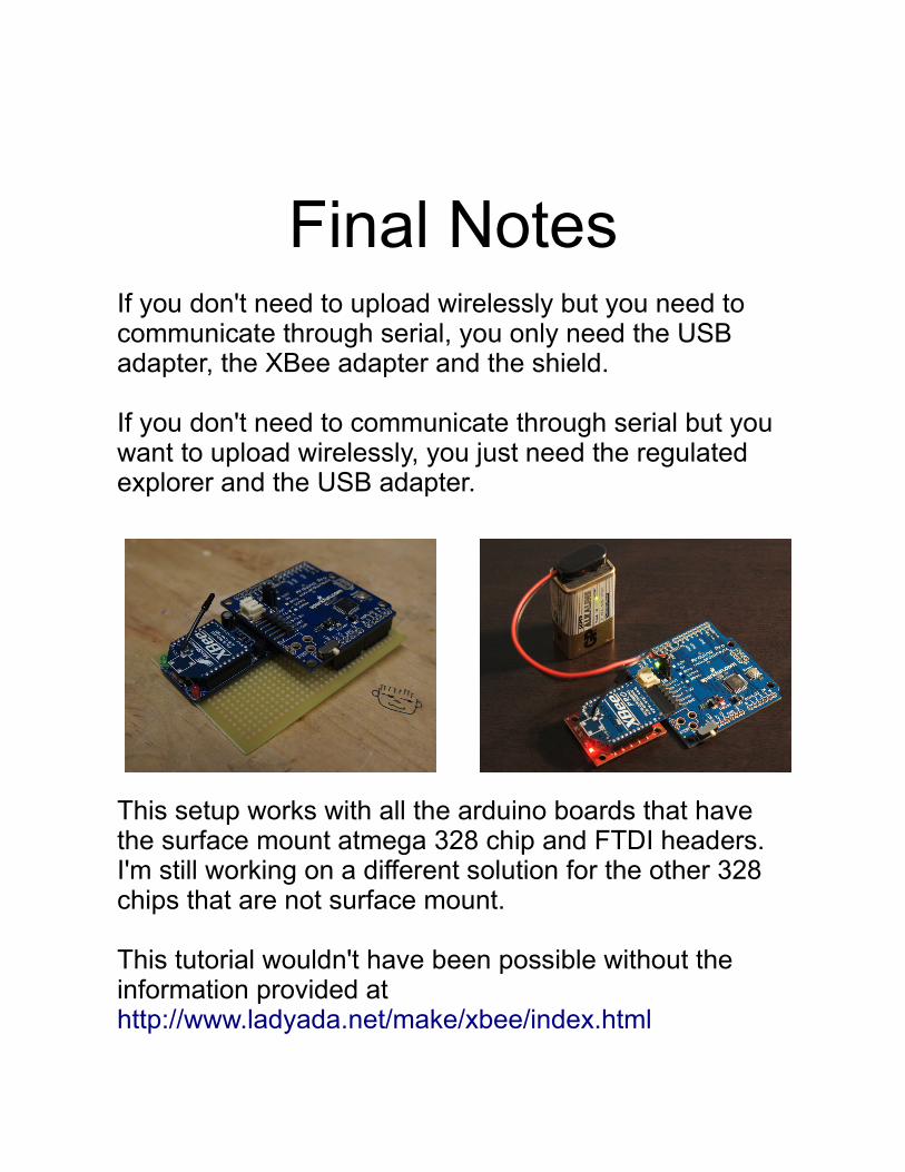
Final NotesIf you don't need to upload wirelessly but you need to communicate through serial, you only need the USB adapter, the XBee adapter and the shield.
If you don't need to communicate through serial but you want to upload wirelessly, you just need the regulated explorer and the USB adapter.
This setup works with all the arduino boards that have the surface mount atmega 328 chip and FTDI headers. I'm still working on a different solution for the other 328 chips that are not surface mount.
This tutorial wouldn't have been possible without the information provided at http://www.ladyada.net/make/xbee/index.html