X9503 2 - Horizon Hobby · JR’s X9503 2.4 offers airplane, helicopter and sailplane pilots...
107
INSTRUCTION AND PROGRAMMING MANUAL X9503 2.4 9-CHANNEL, 50-MODEL MEMORY COMPUTER RADIO SYSTEM WITH SPEKTRUM 2.4GHz DSM TECHNOLOGY
Transcript of X9503 2 - Horizon Hobby · JR’s X9503 2.4 offers airplane, helicopter and sailplane pilots...

INSTRUCTION AND PROGRAMMING MANUAL
X9503 2.49-CHANNEL, 50-MODEL MEMORY COMPUTER RADIO SYSTEM WITH
SPEKTRUM 2.4GHz DSM TECHNOLOGY

Table of ContentsTable of Contents
G-2 G-3
Section 1: Using the Manual ......................................................................................................................... G-9
Features ......................................................................................................................................................... G-9Specifications ................................................................................................................................................ G-9
Section 2: Transmitter and Receiver Specifications ................................................................................. G-9
JR X9503 Transmitter ..................................................................................................................................... G-9
JR R921 Receiver ..........................................................................................................................................G-10
Features .......................................................................................................................................................G-10Specifications ..............................................................................................................................................G-10
Section 3: Component Specifications .......................................................................................................G-11
Servo Specifications ......................................................................................................................................G-11
Charger Specifications .................................................................................................................................G-11
Airborne Battery Pack .................................................................................................................................G-11
Airborne Battery Pack Specifications ...................................................................................................G-11Battery Charging ...........................................................................................................................................G-12
Transmitter/Receiver ....................................................................................................................................G-12
JR Transmitter Charging ...........................................................................................................................G-12Using the Included Charger ....................................................................................................................G-12
X9503 2.4 Transmitter Features (Mode 2 Airplane Shown) ...............................................................G-13
X9503 2.4 Transmitter Features (Rear) ...................................................................................................G-14
Battery Cover ............................................................................................................................................G-14
X9503 2.4 Transmitter Features (Internal) .............................................................................................G-15
Control Stick Tension Adjustment .............................................................................................................G-15
Back of Transmitter (Mode 2) ................................................................................................................G-15
Advanced Digital Trims ................................................................................................................................G-16
Control Stick Length ....................................................................................................................................G-16
Neckstrap Attachment .................................................................................................................................G-16
Installing the Receiver ..................................................................................................................................G-17
Installing the JR R921 ...............................................................................................................................G-17ModelMatch ....................................................................................................................................................G-18
Other Important Installation Tips .........................................................................................................G-18Binding .............................................................................................................................................................G-19
How to Bind ...................................................................................................................................................G-19
Fail-Safe Functions .........................................................................................................................................G-20
SmartSafe ........................................................................................................................................................G-20
Receiver Power Only ...............................................................................................................................G-20After Connection ......................................................................................................................................G-20
Preset Fail-Safe ...............................................................................................................................................G-20
Receiver Power Only ...............................................................................................................................G-20After Connection ......................................................................................................................................G-20
Programming SmartSafe ..............................................................................................................................G-20
(All Spektrum Aircraft Receivers) .........................................................................................................G-20Programming Preset Fail-Safe .....................................................................................................................G-21
(JR R921 and Spektrum AR9000 Receivers Only) .............................................................................G-21
Standard Range Testing ................................................................................................................................G-21
Range Testing the X9503 2.4 ..................................................................................................................G-21Advanced Range Testing Using a Flight Log ............................................................................................G-22
Advanced Range Testing the X9503 2.4 ...............................................................................................G-22Flight Log—Optional for JR R921 Receiver ...........................................................................................G-23
Using the Flight Log ..................................................................................................................................G-23Receiver Power System Requirements ....................................................................................................G-24
Recommended Power System Guidelines ...............................................................................................G-24
Flash Memory ................................................................................................................................................G-25
Battery Alarm and Display ..........................................................................................................................G-25
Tips on Using 2.4GHz Systems .................................................................................................................G-25
Airplane – ACRO Mode .................................................................................................................................A-1
Flight Modes ..................................................................................................................................................A-1
ACRO Programming - Please Read .........................................................................................................A-1
ACRO - Getting Started – System Menu Basics ..................................................................................A-1
Access the System Menu ................................................................................................................................A-2
Select a Model Memory .................................................................................................................................A-2
Reset The Model ..............................................................................................................................................A-3
To Activate the ACRO Mode ........................................................................................................................A-4
Enter a Name for the Model .........................................................................................................................A-4
ACRO - System Menu - Advanced Functions ...........................................................................................A-5
Flight Modes ......................................................................................................................................................A-6
To Activate Flight Modes ................................................................................................................................A-7
TRIM:COM (Flight Modes) ............................................................................................................................A-8
D/R:SW (Flight Modes) ..................................................................................................................................A-8
Switch Assignments .........................................................................................................................................A-9
Flap Trim On/Off ..............................................................................................................................................A-9
Activate/Inhibit Switches ............................................................................................................................. A-10
Wing Type ....................................................................................................................................................... A-11
Wing Parameter – (Wing Type) ................................................................................................................. A-12
V-tail (Wing Type) .......................................................................................................................................... A-14
Dual Channels (Wing Type) ........................................................................................................................ A-14
Twin E. (Wing Type) ...................................................................................................................................... A-16
Trim Step ......................................................................................................................................................... A-18
ACRO – Function List ............................................................................................................................. A-19
REV.SW – Servo Reversing ........................................................................................................................ A-19
SUB TRIM ........................................................................................................................................................ A-20
TRVL ADJ. – Travel Adjust ............................................................................................................................ A-21
D/R & EXP – Dual Rate and Exponential ................................................................................................ A-22
THRO CURV – Throttle Curve ................................................................................................................. A-23
FLAP SYS. – Flap System .............................................................................................................................. A-25
Auto Land (Flap System) ............................................................................................................................. A-26
ELEV – Elevator Compensation (Flap System) ....................................................................................... A-27
Table of Contents Table of Contents
G-4 G-5
FLAP – (Flap System) ................................................................................................................................... A-28
FM0-FM2 (Flap System) ............................................................................................................................... A-29
Delay (Flap System) ...................................................................................................................................... A-30
ELEFLP M – Elevator-to-Flap Mixing .................................................................................................... A-31
AILRUD M – Aileron-to-Rudder Mixing ............................................................................................ A-32
AIL DIFF. – Aileron Differential .................................................................................................................. A-33
SRV. SPEED – Servo Speed .......................................................................................................................... A-35
Snap Roll ......................................................................................................................................................... A-36
GYRO SYS. – Gyro System ......................................................................................................................... A-37
Gyro Connections (Gyro System) ............................................................................................................ A-37
Fixed Gyro Gain (Gyro System) ................................................................................................................ A-38
Stick Override Gyro Gain (Gyro System) ............................................................................................... A-39
PROG MIX – Programmable Mixers ........................................................................................................ A-40
Standard Programmable Mixer – Example: Down Elevator at Idle .................................................... A-41
Multi-Point Mixer – Example: Eliminate Pitch-Coupling ....................................................................... A-43
Trainer – Trainer System ............................................................................................................................. A-45
X9503 Used as Master (Iinstructor) – (Trainer System) ..................................................................... A-45
X9503 2.4 Used as Slave (Student) – (Trainer System) ........................................................................ A-46
Timer – Timer System ................................................................................................................................. A-47
Monitor ........................................................................................................................................................... A-48
Utility Functions ............................................................................................................................................ A-49
Copy – Copy the Currently Selected Model to Another Model Memory ...................................... A-49
Transfer – Transfer the Model to Another Transmitter or to DataSafe ............................................ A-51
Receive a Model into the X9503 2.4 – (Transfer function) ................................................................. A-51
Receive a Model into the X9503 2.4 – (Transfer function) ................................................................. A-52
Sub Trim Usage and Mechanical Advantage ............................................................................................. A-53
Sub Trim ....................................................................................................................................................... A-53Mechanical Advantage .............................................................................................................................. A-53
Dual Rates and Exponential Curves ......................................................................................................... A-54
Setup Sheet (Aircraft) .................................................................................................................................. A-55
X9503 2.4 Helicopter – Heli Mode ........................................................................................................... H-1
Introduction ................................................................................................................................................. H-1
Heli Programming - Please Read ................................................................................................................. H-1
Heli - Getting Started – System Menu Basics ........................................................................................... H-1
Access the System Menu ............................................................................................................................... H-2
Model SEL- Model Selection ......................................................................................................................... H-2
Copy – Copying the Currently Selected Model to Another Model Memory ................................... H-3
Data Reset – Reset the Model ..................................................................................................................... H-5
Type Select – To Activate the Heli Mode ................................................................................................... H-6
MDL Name-Enter a Name for the Model ................................................................................................. H-6
Transfer – Transfer the Model to Another Transmitter or to DataSafe .............................................. H-7
Transfer a Model From the X9503 2.4 – (Transfer function) – To Send ............................................ H-7
Transfer a Model to the X9503 2.4 – (Transfer function) – To Receive ............................................. H-8
Trim Step ........................................................................................................................................................... H-9
Heli - System Menu - Advanced Functions ..............................................................................................H-10
Additional Flight Modes 3 and 4 ................................................................................................................H-10
RUD TRIM: COM – (Flight Mode Trim Options) ...................................................................................H-11
Switch Assignments ......................................................................................................................................H-11
Activate/Deactivate Switches .....................................................................................................................H-12
Governor Program Activation ...................................................................................................................H-12
SWASH TYP-Swashplate Type ....................................................................................................................H-13
Accessing the Swashplate Type Function .................................................................................................H-13
Function Mode...............................................................................................................................................H-14
Heli – Function List ......................................................................................................................................H-14
D/R & EXP – Dual Rate and Exponential ................................................................................................H-14
Auto Dual Rate ..............................................................................................................................................H-15
REV.SW - Servo Reversing .........................................................................................................................H-15
Sub Trim ...........................................................................................................................................................H-16
TRVL ADJ. – Travel Adjust ............................................................................................................................H-17
Swash Mix- CCPM Swashplate Mixing ....................................................................................................H-18
Variations of CCPM Mixing ....................................................................................................................H-18CCPM Servo Connection/Channel Numbers ....................................................................................H-18Accessing the Swashplate Mixing Function .........................................................................................H-19
CCPM Exponential (EXP) ...........................................................................................................................H-19
THRO HOLD- Throttle Hold ....................................................................................................................H-20
Accessing the Throttle Hold Function .................................................................................................H-20Stick Auto/Auto Cut Setting .......................................................................................................................H-21
Hold Delay ......................................................................................................................................................H-21
THRO CURV – Throttle Curves ...............................................................................................................H-22
Accessing the Throttle Curve Function ...............................................................................................H-23Throttle Trim Lever Function .....................................................................................................................H-24
Hovering Throttle Lever ..............................................................................................................................H-24
Throttle Curve Exponential .......................................................................................................................H-24
Accessing the Throttle Curve Exponential Function ........................................................................H-24PIT. CURV/Pitch Curves Function .............................................................................................................H-25
Accessing the Pitch Curve Function .....................................................................................................H-25Hovering Pitch Lever ....................................................................................................................................H-26
Example of Throttle Curve and Pitch Curve Settings ......................................................................H-26Accessing the Revolution Mixing Function .........................................................................................H-27Setting up Revolution Mixing..................................................................................................................H-27
REVO.MIX/Revo Mix Function: Non Heading Lock Gyros Only .......................................................H-27
GYRO SENS/Gyro Gain Function .............................................................................................................H-28
Accessing the Gyro Gain Function .......................................................................................................H-28Gyro Remote Gain Connections: JR G370, G770 and Others .....................................................H-29
Remote Gain Gyros .....................................................................................................................................H-29
Mixing – Cyclic-to-Throttle Mixing ...........................................................................................................H-29
Rudder-to-Throttle Mixing .........................................................................................................................H-30
Accessing the Cyclic-to-Throttle Function .........................................................................................H-31

Table of Contents Table of Contents
G-6 G-7
Aileron-to-Throttle and Elevator-to-Throttle Mixing ...........................................................................H-31
Setting the Desired Flight Modes for Cyclic-to-Throttle Mixing ...................................................H-31Governor- Governor Function ..................................................................................................................H-32
Accessing the Governor Function ........................................................................................................H-32PROG MIX 1-6 – Programmable Mixes 1 through 6 ............................................................................H-33
Swashplate Timing Mixes Example: Elevator-to-Aileron (Corrects Vertical Tracking)....................H-35
Swashplate Timing: Aileron-to-Elevator (Corrects Rolling Maneuvers) ............................................H-37
Standard Programmable Mixes – Example: Right Aileron with Positive Pitch .............................H-39Multi-Point Mixes – Example: FMOD to Gear Mixing (Retract and other Functions)..................H-41
Trainer – Programmable Trainer System..................................................................................................H-44
X9503 2.4 Used as Master (Instructor) – (Trainer System) ...........................................................H-44X9503 2.4 Used as Slave (Student) – (Trainer System) ...................................................................H-45
Timer – Timer System .................................................................................................................................H-46
Monitor – Servo Monitor ...........................................................................................................................H-47
Setup Sheet (Helicopter) .............................................................................................................................H-48
Sailplane – GLID Mode....................................................................................................................................S-1
System Mode GLID Features .....................................................................................................................S-1
Function Mode GLID Features ..................................................................................................................S-1
System Mode ......................................................................................................................................................S-2
System Mode ......................................................................................................................................................S-2
To Enter System Mode: ................................................................................................................................S-2Model Select .......................................................................................................................................................S-3
Copy – Copying the Currently Selected Model to Another Model Memory .....................................S-4
Model Name ......................................................................................................................................................S-6
Type Select ..........................................................................................................................................................S-6
Model Reset .......................................................................................................................................................S-7
Transfer – Transfer the Model to Another Transmitter or to DataSafe ................................................S-8
Transfer a model from the X9503 2.4 – (Transfer Function) .................................................................S-8
Transfer a model to the X9503 2.4 – (Transfer Function) ......................................................................S-9
Trim Step .......................................................................................................................................................... S-10
Device Select ................................................................................................................................................... S-11
Flight Modes ................................................................................................................................................ S-11
Activating and Assigning Flight Modes ....................................................................................................... S-12
Motor Function .............................................................................................................................................. S-13
Flap and AUX Functions ............................................................................................................................... S-14
Activating / Inhibiting Channels .............................................................................................................. S-14Wing Type ........................................................................................................................................................ S-15
Function Mode ........................................................................................................................................... S-16
D/R & EXP – Dual Rate and Exponential ................................................................................................. S-18
REV.SW – Servo Reversing ......................................................................................................................... S-19
Sub Trim ............................................................................................................................................................ S-20
TRVL. ADJ - Travel Adjust ............................................................................................................................. S-21
Elevator-to-Flap Mix ...................................................................................................................................... S-21
Aileron-to-Flap Mix ....................................................................................................................................... S-22
Differential ....................................................................................................................................................... S-22
Camber Adjust ................................................................................................................................................ S-23
Camber Mix .................................................................................................................................................... S-24
Aileron-to-Rudder Mix ................................................................................................................................. S-25
Butterfly Mix (Landing Flaps) ....................................................................................................................... S-26
Flap Rate........................................................................................................................................................... S-27
Motor Hold ..................................................................................................................................................... S-27
Programmable Curve Mix 1 (Programmed for Spoiler-to-Elevator Mix).......................................... S-28
PROG MIX - Programmable Mixers .......................................................................................................... S-29
Multi-Point Programmable Mixer ............................................................................................................... S-33
Trainer – Programmable Trainer System................................................................................................... S-36
X9503 2.4 Used as Master (Instructor) – (Trainer System) ............................................................ S-36X9503 2.4 Used as Slave (Student) – (Trainer System) .................................................................... S-37
Timer ................................................................................................................................................................ S-37
Monitor ............................................................................................................................................................ S-38
Programming a 6-Channel Sailplane by Engineering Manager John Adams ...................................... S-39
Channel Assignment .................................................................................................................................. S-41Step #1 Servo Assignment .......................................................................................................................... S-41
Step #2 System Mode ................................................................................................................................... S-42
Step #3 Selecting a Model Memory ........................................................................................................... S-42
Step #4 Selecting Model Type...................................................................................................................... S-43
Step #5 Naming a Model .............................................................................................................................. S-43
Step #6 Turning Off the Spoiler Stick Trim ............................................................................................... S-44
Step #7 Establishing Flight Modes .............................................................................................................. S-44
Step #8 Wing and Tail Type Select .............................................................................................................. S-45
Step #9 Entering FUNC.LIST ...................................................................................................................... S-45
Step #10 Servo Reversing ............................................................................................................................ S-46
Step #11 Sub Trim .......................................................................................................................................... S-47
Step #12 Travel Adjust ................................................................................................................................... S-48
Step #13 Butterfly (Landing Flaps) ............................................................................................................. S-48
Setting Up Flight Modes ........................................................................................................................... S-49Launch Mode Setup ................................................................................................................................... S-49
Step #14 Spoiler to Elevator Curve Mix (Programmable Mix 1) ....................................................... S-49
Step #15 Launch Pre-sets ............................................................................................................................ S-50
Step #16 Dual Rate and Exponential ......................................................................................................... S-51
Step #17 Elevator-to-Flap Mix .................................................................................................................... S-51
Step #18 Aileron-to-Flap .............................................................................................................................. S-52
Step #19 Aileron Differential ....................................................................................................................... S-52
Flaperon Mix ............................................................................................................................................... S-53Step #20 Flap Rate, Camber Mix and Camber Adjust ........................................................................... S-53
Step #21 Flap Rate, Camber Mix and Camber Adjust (continued) .................................................... S-54
Flaperon Mix ............................................................................................................................................... S-54Flaperon Mix Delay .................................................................................................................................... S-54Setting up Cruise Mode ............................................................................................................................ S-55
Step #22 Aileron-to-Rudder Mix ............................................................................................................. S-55
Step #23 Cruise Pre-sets ............................................................................................................................. S-56
JR X9503 Transmitter
Section 2: Transmitter and Receiver Specifications
Section 1: Using the Manual
G-8 G-9
JR’s X9503 2.4 offers airplane, helicopter and sailplane pilots sophisticated programming that JR’s 9303 is famous for with the added benefits of a backlight screen, 50-model memory, and new throttle timer start for aircraft and helicopter model types plus fully integrated Spektrum 2.4GHz DSM® radio link technology. DSM (Digital Spektrum Modulation) technology offers a far superior RF link than narrow band 72MHz FM and PCM systems, providing a higher level of confidence and
safety. Now with even the most sophisticated models up to 9 channels, you’ll no longer have to wait for an open frequency, worry about someone unintentionally powering up on the same frequency, or have to plan a frequency-based flight matrix for competition. And for response-critical aircraft like 3D helicopters and airplanes, latency (the time it takes for a stick input to translate to a servo output) is significantly reduced providing a more responsive precise connection to your model.
Features
•Fullyintegrated2.4GHzSpektrumRFlink
•Sophisticatedthree-model-typeprogramming:Airplane,Helicopter,Sailplane
•PatentedDuaLink® technology
•ModelMatch™
•ServoSync™
•RollingSelectorinput
•Digital3+1trims
•50-modelmemory
•Backlightscreen
Specifications
•Modelnumber—Airplane/Sailplane(JRP2930),Helicopter(JRP2935)
•Numberofchannels—9
•Modulationtype—DirectSequenceSpreadSpectrumDSM2/DSM1protocol
•Band—2.400to2.483GHz
•Spectralcapacity—40simultaneoussystems
•Transmittercurrent—180mA/DSM2280mA/DSM1
•Resolution—2048withR921receiver
In the front of this manual you will find common transmitter features and specifications plus information on the included components and accessories. Guidelines for receiver and servo installation are also included. In each section of this manual (Air, Heli and Sailplane) are instructions for adjusting model-specific programming and functions. An explanation of the purpose of each programming function is provided, followed by an illustrationofitscorrespondingLCDdisplayandinstructions on how to access and adjust the function.
A blank data sheet has been included at the end of each section, as well as on the JR web site. Once all data has been input for a particular model, you should record these values and settings on a copy of the data sheet, so in the rare event of a loss of memory, these settings are available.
Note:ThemanualfortheX95032.4manualispostedonline at www.horizonhobby.com in the support section or it can be ordered from your local hobby dealer or directly from Horizon Hobby.
Step #24 Dual Rate and Exponential ......................................................................................................... S-56
Step #25 Elevator-to-Flap Mix .................................................................................................................... S-57
Step #26 Aileron-to-Flap .............................................................................................................................. S-58
Step #27 Aileron Differential ....................................................................................................................... S-58
Flap Rate ...................................................................................................................................................... S-59Flaperon Mix ............................................................................................................................................... S-59
Step #28 Flap Rate, Camber Mix and Camber Adjust ........................................................................... S-59
Step #29 Flap Rate, Camber Mix and Camber Adjust (continued) .................................................... S-60
Flaperon Mix Delay .................................................................................................................................... S-60Setting Up Land Mode .............................................................................................................................. S-61
Step #30 Aileron-to-Rudder Mix .............................................................................................................. S-61
Step #31 Land Pre-sets ................................................................................................................................. S-62
Step #32 Dual Rate and Exponential ......................................................................................................... S-63
Step #33 Elevator-to-Flap Mix .................................................................................................................... S-64
Step #34 Aileron-to-Flap .............................................................................................................................. S-64
Step #35 Aileron Differential ....................................................................................................................... S-64
Flaperon Mix ............................................................................................................................................... S-65Flaperon Mix ............................................................................................................................................... S-65
Step #36 Flap Rate, Camber Mix and Camber Adjust ........................................................................... S-65
Step #37 Flap Rate, Camber Mix and Camber Adjust (continued) .................................................... S-66
Step #38 Aileron-to-Rudder Mix .............................................................................................................. S-66
Flaperon Mix Delay .................................................................................................................................... S-66Setup Sheet (Sailplane) .................................................................................................................................. S-67
Servo Precautions .......................................................................................................................................... W-1
General Notes ................................................................................................................................................ W-1
Federal Aviation Administration .................................................................................................................. W-2
1. Purpose .................................................................................................................................................... W-22. Background .............................................................................................................................................. W-23. Operating Standards ............................................................................................................................. W-2Warning ........................................................................................................................................................ W-3Warranty Period ........................................................................................................................................ W-3Limited Warranty ....................................................................................................................................... W-3Damage Limits ............................................................................................................................................ W-3Safety Precautions ...................................................................................................................................... W-3Questions, Assistance, and Repairs ........................................................................................................ W-3
Warranty and Service Information ............................................................................................................ W-3
Warranty and Service Information ............................................................................................................ W-4
Inspection or Repairs ................................................................................................................................ W-4Warranty Inspection and Repairs ........................................................................................................... W-4Non-Warranty Repairs ............................................................................................................................. W-4Safety, Precautions, and Warnings ........................................................................................................... W-4Instructions for Disposal of WEEE by Users in the European Union ............................................ W-5FCC Information ........................................................................................................................................ W-5

JR R921 Receiver
Charger Specifications
Section 3: Component Specifications
G-10 G-11
TheR921receivercombinestwointernalwithoneortwo (optional) remote receivers, offering superior path diversity.Theradiosystemsimultaneouslytransmitson two frequencies, creating up to four RF paths on two different2.4GHzchannels.Thismulti-pathredundancy,plus the fact that each of the up to 4 receivers are located in different locations throughout the aircraft exposes each
to a different RF environment creating a superior RF linkinallconditions.TheJRR921allowstheuse ofanoptionalFlightLogDataRecorder(JRPA145)to beused.TheFlightLogplugsintothedataportandprovides quality of RF link data of the previous flight allowing the confirmation of the operational performance of the systems.
Features
•9channels
•2internalreceivers
•1or2(optional)remotereceiver(s)
•PatentedMultiLinktechnology
•Twotypesoffail-safe—SmartSafe™ and Preprogrammed fail-safe
•FlightLogcompatible
Specifications
•Numberofchannels—9
•Modulation—DSM2
•Band—2.400to2.4835GHz
•Dimensions(WxLxH)—1.23x1.94x.56in
•Weight—Main15g/.6ozRemote3g/.2ozeach
•Current—70mA
•Voltagerange—3.5to9.6V
Note:TheX95032.4isalsocompatiblewithallcurrentJRandSpektrumDSMaircraftreceiversincluding:
AR5005-channel,AR6000,AR6100/E,AR6110/E,AR6300,AR6400/L6-channelparkflyer
AR6200,AR62506-channelfullrange
AR7000,AR7100,AR76007-channelfullrange
AR9000,AR9100,AR93009-channelfullrange
R9229-channelfullrangeandR1221,R122212-channelfullrange
Important:WhenusingtheX95032.4withparkflyerreceivers(theAR6000,AR6100/E,AR6110/E,AR6300andAR6400),it’simperativethatthesereceiversonlybeflowninparkflyer-typeaircraft(smallelectricairplanesorminiand micro helicopters). Flying receivers designed for parkflyers in larger aircraft could cause loss of control.
Model Number AD35M05
InputVoltage AC120V,60Hz
OutputCurrent 11.6VTransmitter/110mAh,5.8VReceiver/110mAh
ChargingTime 15hours

Transmitter/Receiver
Battery Charging X9503 2.4 Transmitter Features (Mode 2 Airplane Shown)
50FEATURING 2048 RESOLUTION
G-12 G-13
Note:Youshouldfullychargeboththetransmitterand the receiver battery packs prior to each flying session. Also, check the condition of the receiver battery between each flight using a reliable battery testerwithabuilt-inload.Theincludedwallchargerslowchargesata110mArate.Inordertofullycharge the included batteries, you should leave the charger and batteries hooked up to the included wall chargerfor15hours.
Youcanuseanoptionalfastchargertochargeboththetransmitter and receiver batteries. However, the batteries must be properly charged and the charge condition should be checked prior to flight. False peaking is a common occurrence with many fast chargers (batteries giving an indication the battery is fully charged when in fact the battery is only partially charged). False peaking can lead to disastrous results and it is the pilot’s responsibility to verify the charge condition of the batteries before every flight. (Also see Receiver Power Requirements page G-24)
JR Transmitter Charging
ThecenterpinonallJR® and Spektrum™ transmitters is negative.Therefore,thecenterpinonallJRchargersisnegative,notpositive.Thisisdifferentfrommanyothermanufacturers’chargersandradiosystems.Bewareofimproper connections based on “color-coded” wire leads, astheymaynotapplyinthisinstance.Youmustmakesure that the center pin of your JR transmitter is always connected to the negative pole for correct polarity.
Note:Whenusingafastchargertochargethetransmitterbatterydonotexceed1.5amps(or1500mAh)chargerateordamagetothetransmitteror battery damage can occur.
Using the Included Charger
Thepilotlampsshouldalwaysbeonduringthechargingoperation. If not, check to make sure that both the transmitter and receiver are switched off.
DonotusethechargerforequipmentotherthanJR.Thechargingplugpolaritymaynotbethesame.Equipmentdamage can result.
Do not use other manufacturers’ after-market accessories that plug into the transmitter’s charging jack if you are unsure of the polarity compatibility with your radio. Seek expert advice to avoid possible damage.
During the charging operation, the charger’s temperature is slightly elevated.
All preprogrammed data is protected by a flash memory that guards against main transmitter battery failure.
CENTER PIN IS
NEGATIVE
OUTSIDE IS POSITIVE
CHARGER PIGTAIL FOR RECEIVER
CHARGER PIGTAIL FOR TRANSMITTER
BLACK TO POSITIVE
RED TO NEGATIVE
RIGHT SIDE OF TRANSMITTER
RED–POSITIVE / BROWN–NEGATIVE / ORANGE–SIGNAL
TrainerButton
Gear Switch
Flap Switch
Elevator Dual Rate
FlapTrim
Lever
AUX4/ Rudder Dual
RateAuxTrim
Aileron Dual Rate
AUX2
Mix Switch
Lever
Elevator/ Aileron Stick
Throttle/ Rudder Stick
RudderTrim
ThrottleTrim
ListButton
EnterButton
ClearButton
Power Switch
AileronTrim
ElevatorTrim
Rolling Selector
LCDDisplay

X9503 2.4 Transmitter Features (Rear) X9503 2.4 Transmitter Features (Internal)
Control Stick Tension Adjustment
G-14 G-15
Remove the six transmitter screws from the back cover as shownonpageG-14.Removethetransmitterback,beingcareful not to cause damage to any components.
Adjust each gimbal tension screw for desired tension (counterclockwise to loosen stick tension; clockwise to tightensticktension).Whenadjustingthethrottleratchettension, make sure that the adjusting screw does not touch the PC board after adjustment is complete.
Model No. X9503
Horizon Hobby, Inc. Made in Malaysia
U.S. Patent 7,391,320
DC 11.6V
Battery CoverCAUTION:THEBATTERYCONNECTIONISKEYEDSOTHATITCANONLY
BEPLUGGEDINONEDIRECTION.DONOTFORCE.
Back of Transmitter (Mode 2)
THROTTLETENSIONSCREW
RUDDERTENSIONSCREW
ELEVATORTENSIONSCREW
AILERONTENSIONSCREW

Control Stick Length
Neckstrap Attachment
Installing the Receiver
G-16 G-17
Advanced Digital Trims
TheX95032.4featuresAdvancedDigitalTrims.OntheNormal display screen, if a trim lever is moved, the screen will automatically change to display the graphic position forthetrimbeingadjusted.TheX95032.4’sAileron,Elevator,andRuddertrimleversfeatureanaudiblecentertrimbeep.Thisishelpfulindeterminingthetrimlevers’center position during flight. In addition, the frequency of eachtrimstepchangesfromfullright/uptofullleft/down,allowing the pilot to be aware of the general trim position audibly without looking at the transmitter.
ByusingtheTrimStepFunctionlocatedintheSystemMode, you can adjust the amount of travel per each trim step for your specific application.
Please note, when you turn it off, the X9503 stores the trim values in memory and recalls them when turned back on.
Use a 2mm Allen wrench to unlock the setscrew to adjust thesticklength.Turnthewrenchcounterclockwisetoloosenthescrew.Then,turnthestickclockwisetoshortenor counterclockwise to lengthen the overall stick length. After the control stick length has been adjusted to suit your flying style, tighten the 2mm setscrew. If you desire longer sticks, JR offers a stick (JRPA047) that is approximately one inch longer than standard, and has various length anodized aluminum stick ends available (JRPA040-JRPA045).Thesestickendsarecraftedfrombarstockaluminum, and are available at your local JR dealer.
An eyelet provided on the face of the X9503 transmitter allows youtoconnectaNeckStrap(JRPP607).Neckstrapadaptorsare also available to customize the balance of the transmitter (JRPA140-JRPA142andSPM6703).
Installing the JR R921
TheJRR921incorporatesdualinternalreceivers,andoneor two remote receivers offering the security of up to four simultaneous RF links for the ultimate in multi-path RF security.ThemainPCboardhastwointernalreceivers,while a third remote receiver must be plugged into one of the antenna ports in order for the system to operate. Optionally, you can plug a second remote receiver into the remaining remote antenna port giving a total of four operationalreceivers.Bylocatingthesereceiversindifferent locations throughout the aircraft, each receiver is exposed to its own RF environment, greatly improving path diversity.
Note:TheJRR921requiresatleastoneremotereceiver be used.
Install the main receiver using the same method you would use to install a conventional receiver in your aircraft.Typicallywrapthemainreceiverinprotectivefoam and fasten it in place using rubber bands or hook and loop straps. Alternately in electric models or in jets (low vibration), it’s acceptable to use thick double-sided foam tape to fasten the main receiver in place.
Mounting the remote receiver(s) in a different location(s) from the primary receiver, gives tremendous improvementsinpathdiversity.Essentiallyeachreceiversees a different RF environment and this is the key to maintaining a solid RF link, even in aircraft that have substantial conductive materials, (e.g. turbine engines with metal tail pipes, carbon fiber, tuned pipes, etc.) which can weaken the signal.
Using double-sided foam tape, (servo tape) mount the remote receiver(s) keeping the remote antenna(s) at least 2 inches away from the primary antenna. Ideally the antennas will be oriented perpendicular to each other; however,we’vefoundthistonotbecritical.6-inch,9-inch,12-inch,24-inchand36-inchleadsareavailableand in sophisticated aircraft, we’ve found it best to mount the remote receivers in different parts of the aircraft keeping the remote antennas as far away as practical from any conductive materials. A typical installation would include the main receiver mounted in the conventional location in the fuselage and the remote antennas in the nose(jets)inthetopturtledeckandeveninthetail.Theoptimum location is as far away from any conductive materials as practical.
LOOSEN
TIGHTEN
SETSCREW

G-18 G-19
In helicopters, there is generally enough room on the servo tray to achieve the necessary separation. If necessary, a mount can be made using clear plastic to mount the remote receiver as shown below.
Other Important Installation Tips
1. Mounttheservosusingrubbergrommetsandbrasseyelets to isolate them from vibration. Do not over-tighten the mounting screws; this will negate the vibrationabsorptioneffectoftherubbergrommets.Thefollowing diagram will assist you in properly mounting your servo.
Thebrasseyeletsarepushedfromthebottomupintherubbergrommets.Whentheservoscrewistightenedsecurely, it provides the proper security as well as the proper vibration isolation for your servo.
2. Theservosmustbeabletomovefreelyovertheirentire range of travel. Make sure that the control linkages do not bind or impede the movement of any of the servos.
3. Mount all switches away from the engine exhaust and away from any high-vibration areas. Make sure the switch operates freely and is able to operate over its full travel.
It’s necessary to program the receiver to the transmitter so that the receiver will only recognize that specific transmitter, ignoring signals from any other sources. If the receiver is not bound to the transmitter, the system will not operate. During binding, the servo’s fail-safe positions are stored.
ThefollowingsequencedescribesthebindingprocedurefortheJRR921;however,allJRandSpektrumDSMaircraft receivers are bound in the same way.
How To Bind1. Withthesystemhookedupasshown,insertthebind
pluginthechargeplugreceptacle.Theswitchmustbea3-wiretypeswitch(JRPA001orJRPA004)toenterbind mode through the switch. Plug the receiver’s power lead from the switch into the receivers bind port. If a 3-wire switch is not available, install the male bind plug into the bind plug receptacle and power the receiver through any other open port to enter bind mode.
REMO
VE BEFORE U
SE
2. Poweronthereceiver.NotethattheLEDsonallreceivers should be flashing, indicating that the receiver is ready to bind.
AR90
00
3. Establishthedesiredfail-safestickpositions:normallylow throttle and flight controls neutral.
4. Press and hold the bind button on the back of the transmitterwhileturningonthepowerswitch.Thebind button should flash and can then be released, and withinafewsecondsthesystemshouldconnect.TheLEDsonthereceiversshouldgosolid,indicatingthesystem has connected.
5. Remove the bind plug from the receiver or switch harness and store it in a convenient place.
6. Afteryou’veprogrammedyourmodel,it’simportanttorebind the system so the true low throttle and neutral control surface positions are programmed.
Note:Tobindanaircraftwithanelectronicspeedcontroller that powers the receiver through the throttlechannel(BEC),insertthebindplugintothebattery port and proceed to Step #2.
Binding
ModelMatchTheX95032.4featuresModelMatchtechnologythatprevents the operation of a model if the wrong model memory is selected. During binding, the receiver actually learnsandremembersthespecificmodelmemory(1thru50)thatthetransmitteriscurrentlyprogrammedto.Laterifthe incorrect model memory in the transmitter is selected and the receiver is turned on, the model simply won’t operate, preventing a possible crash. Change programming to the correct model memory and you’re set to fly.
ServoMountingTab
Screw
Rubber Grommet
BrassEyelet
G-20 G-21
TheJRR921receiverfeaturestwotypesoffail-safe:SmartSafe and Preset Fail-safe.
SmartSafe
Thistypeoffail-safeisespeciallyidealformosttypesofelectric aircraft and is also recommended for most types of gas- and glow-powered airplanes and helicopters. Here’s how SmartSafe works.
Receiver Power Only
Whenthereceiveronlyisturnedon(notransmittersignalis present), all servos except for the throttle are driven to their preset fail-safe positions, normally control surfaces atneutralandthelandinggeardown.Thesefail-safepositions are stored in the receiver during binding. At this time the throttle channel has no output, to avoid operating or arming the electronic speed control. In glow-powered models, the throttle servo has no input so it remains in its current position.
After Connection
Whenthetransmitteristurnedonandafterthereceiverconnects to the transmitter, normal control of all channels occurs. After the system makes a connection, if loss of signal occurs, SmartSafe drives the throttle servo only to its preset fail-safe position (low throttle) that was set during binding. All other channels hold their last position. Whenthesignalisregained,thesystemimmediately(lessthan 4 ms) regains control.
Preset Fail-Safe
Preset fail-safe is ideal for sailplanes and preferred by some modelers for their glow- and gas-powered aircraft.
Receiver Power Only
Whenthereceiveronlyisturnedon(notransmittersignalis present) all servos except for the throttle are driven to their preset fail-safe positions, normally control surfaces atneutralandthelandinggeardown.Thesefail-safepositions are stored in the receiver during binding. At this time the throttle channel has no output, to avoid operating or arming the electronic speed control. In glow-powered models, the throttle servo has no input so it remains in its current position.
After Connection
Whenthetransmitteristurnedonandafterthereceiverconnects to the transmitter, normal control of all channels occurs. After the system makes a connection, if loss of signal occurs preset fail-safe drives all servos to their preset fail-safe positions. For sailplanes, it’srecommendedthatthespoilers/flapsdeploytode-thermalize the aircraft, preventing a flyaway. Some powered modelers prefer to use this fail-safe system to program a slight turn and low throttle to prevent their aircraftfromflyingaway.Whenthesignalisregained,thesystem immediately (in less than 4 ms) regains control.
Programming SmartSafe
(All Spektrum Aircraft Receivers)
Leavethebindpluginduringthebindingprocessand remove it only after the receiver connects to the transmitter. After the connection is made, confirmed by operatingtheservos,removethebindplug.Thereceiveris now programmed for SmartSafe.
Fail-Safe Functions
(JR R921, R922, R1221, R1222 and Spektrum AR7100, AR7100R, AR7600, AR9000, AR9100 Receivers Only)
During the binding process, insert the bind plug in the bind port or in the charge jack, as the receiver is powered up. TheLEDsineachreceivershouldblink,indicatingthatthereceiverisinbindmode.Beforebindingthereceivertothetransmitter and with the receiver in bind mode, remove the bindplug.TheLEDswillstillbeblinking.Withthecontrolsticks and switches in the desired fail-safe positions, bind the transmitter to the receiver by pressing and holding the bindbuttonsonthebackofthetransmitter/moduleandturningonthetransmitter.Thesystemshouldconnectinlessthan15seconds.Thereceiverisnowprogrammedfor
preset fail-safe.
Note:Fail-safepositionsarestoredviathestickandswitch positions on the transmitter during binding.
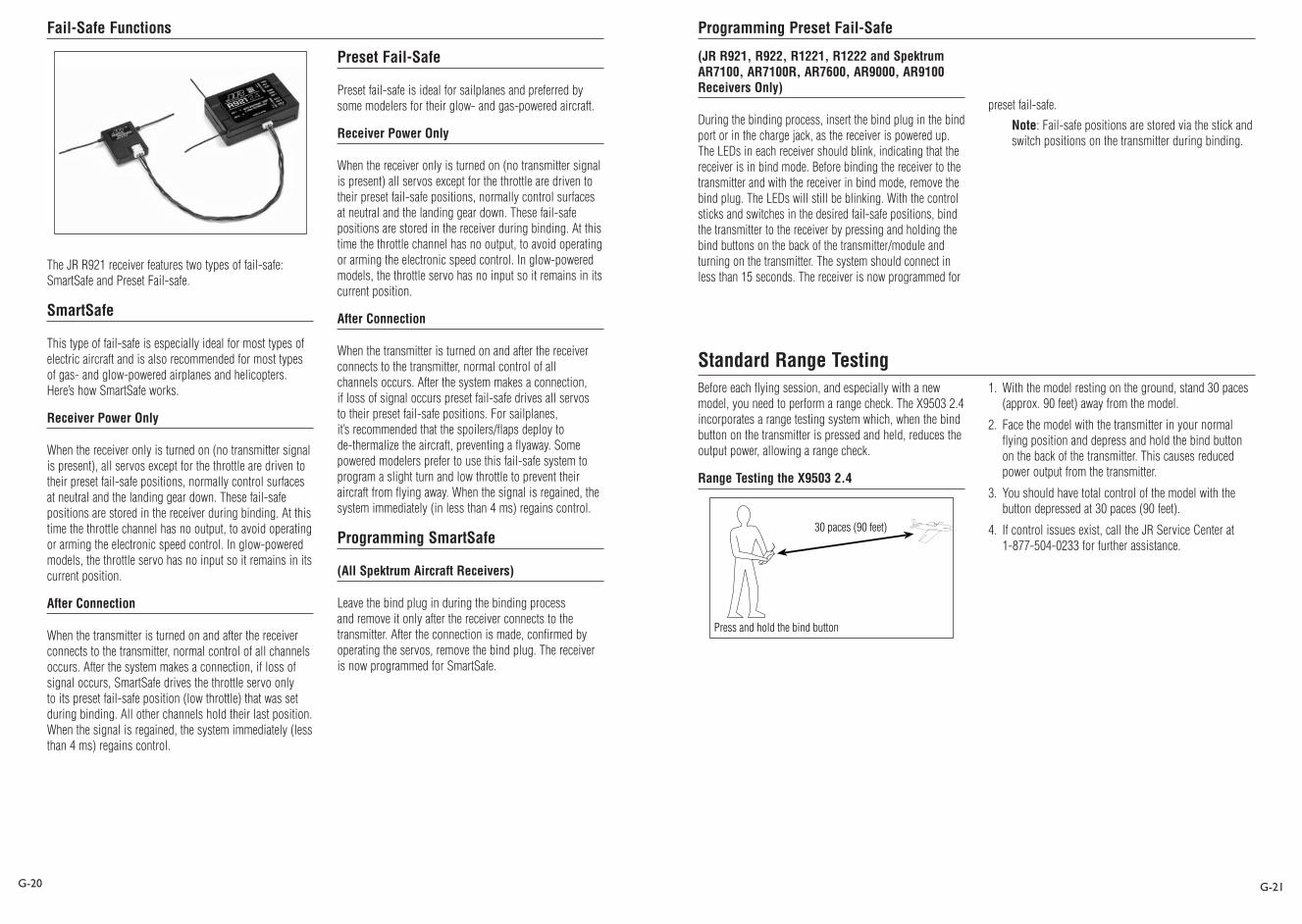
Standard Range TestingBeforeeachflyingsession,andespeciallywithanewmodel,youneedtoperformarangecheck.TheX95032.4incorporates a range testing system which, when the bind button on the transmitter is pressed and held, reduces the output power, allowing a range check.
Range Testing the X9503 2.4
Press and hold the bind button
30 paces (90 feet)
1. Withthemodelrestingontheground,stand30paces(approx. 90 feet) away from the model.
2. Face the model with the transmitter in your normal flying position and depress and hold the bind button onthebackofthetransmitter.Thiscausesreducedpower output from the transmitter.
3. Youshouldhavetotalcontrolofthemodelwiththebutton depressed at 30 paces (90 feet).
4. If control issues exist, call the JR Service Center at 1-877-504-0233forfurtherassistance.
Programming Preset Fail-Safe

G-22 G-23
WhiletheaboveStandardRangeTestingprocedureisrecommended for most sport aircraft, for sophisticated aircraftthatcontainsignificantamountsofconductive/reflective materials (e.g. turbine-powered jets, some types of scale aircraft, aircraft with carbon fuselages, etc.) the following advanced range check will confirm that all internal and remote receivers are operating optimally and that the installation (position of the receivers) is optimizedforthespecificaircraft.ThisAdvancedRangeCheck allows you to evaluate the RF performance of each individual internal and remote receiver and to optimize the locations of each individual remote receiver.
Advanced Range Testing the X9503 2.4
1. Plugaflightlog(optional)intothedataportintheJRR921receiverandturnonthesystem(transmitterandreceiver).
2. AdvancetheFlightLoguntilF-framelossesaredisplayed, by pressing the button on the flight log.
3. Haveahelperholdyouraircraftwhilehe/sheobservestheFlightLogdata.
4. Standing 30 paces away from the model, face the model with the transmitter in your normal flying position. Depress and hold the bind button on the back ofthetransmitter.Thiscausesreducedpoweroutputfrom the transmitter.
5. Have your helper position the model in various orientations (nose up, nose down, nose toward the transmitter, nose away from the transmitter, etc.) while yourhelperiswatchingtheFlightLog,notinganycorrelation between the aircraft’s orientation and Frame Losses.Dothisfor1minute.ThetimerontheX9503canbeusedhere.Tiptheairplaneuponitsnoseandrotateit360degreesforoneminute,thenrecordthedata. Next place the airplane on its wheels and do a second test, rotating the aircraft in all directions for one minute.
6. Afteroneminute,releasethebindbutton.Asuccessfulrange check will have recorded zero frame losses. ScrolltheFlightLogthroughtheAntennafades (A,B,L,R)toevaluatetheperformanceofeachreceiver. Antenna fades should be relatively uniform. If a specific antenna is experiencing a high degree of fades, then that antenna should be moved to a different location.
7. A successful Advanced test will yield the following.
H - 0 holds
F - 0 frame losses
A,B,R,L-Antennafadeswilltypicallybelessthan100.Compare the relative antenna fades and if a particular receiver has significantly higher antenna fades (2 to 3X), then the test should be redone. If the same results occur, move the offending receiver to a different location.
Advanced Range Testing Using a Flight Log
TheFlightLogiscompatiblewithJRR921receivers.TheFlightLogdisplaysoverallRFlinkperformanceaswellas the individual internal and external receiver link data. Additionally it displays receiver voltage.
Using the Flight Log
After a flight and before turning off the receiver or transmitter,plugtheFlightLogintotheDataportontheJRR921receiver.Thescreenwillautomaticallydisplayvoltagee.g.6v2=6.2volts.
Note:Whenthevoltagereaches4.8voltsorless,the screen will flash indicating low voltage.
Press the button to display the following information.A - Antenna fades on internal antenna A
B-AntennafadesoninternalantennaB
L-Antennafadesontheleftexternalantenna
R - Antenna fades on the right external antenna
F - Frame loss
H - Holds
Antennafades—representsthelossofabitofinformationon that specific antenna.
Typicallyit’snormaltohaveasmanyas50to100antennafades during a flight.
If any single antenna experiences over 500 fades in a single flight, the antenna should be repositioned in the aircraft to optimize the RF link.
Frameloss—representssimultaneousantennafadeson all attached receivers. If the RF link is performing optimally, frame losses per flight should be less than 20.
A hold occurs when 45 continuous (one right after the other) frame losses occur.
Thistakesaboutonesecond.Ifaholdoccursduringa flight, you should re-evaluate the system. Move the antennastodifferentlocationsand/orchecktobesurethetransmitter and receivers are all working correctly.
Note:AservoextensioncanbeusedtoallowtheFlightLogtomoreconvenientlybepluggedinwithouthaving to remove the aircraft’s hatch or canopy. On somemodels,theFlightLogcanbepluggedin,attached and left on the model using double-sided tape.Thisiscommonwithhelicopters,mountingtheFlightLogconvenientlytothesideframe.
Flight Log—Optional for JR R921 Receiver

G-24 G-25
Withallradioinstallations,theonboardpowersystemmust provide adequate power without interruption to the receiver even when the system is fully loaded (servos at maximumflightloads).Thisbecomesespeciallycriticalwithgiant-scalemodelsthatutilizemultiplehigh-torque/high-current servos. Inadequate power systems that do not provide the necessary minimum voltage to the receiver during flight loads are the number one cause of in-flight failures. Some of the power system components that affect theabilitytoproperlydeliveradequatepowerinclude:theselected receiver battery pack (number of cells, capacity, cell type, state of charge), switch harness, battery leads, regulator (if used), power bus (if used).
WhiletheR921receivers’minimumoperationalvoltageis3.5-volts, you should test the system per the guidelines belowtoaminimumacceptablevoltageof4.8-voltsduringgroundtesting.Thisprovidesheadroomtocompensate for battery discharging or if the actual flight loads are greater than the ground test loads.
Recommended Power System Guidelines1. Whensettinguplargeorcomplexaircraftwithmultiple
high-torque servos, you should use a current and voltmeter(Hangar9HAN172).Plugthevoltmeterinanopen channel port in the receiver and with the system on, load the control surfaces (apply pressure with your hand)whilemonitoringthevoltageatthereceiver.Thevoltage should remain above 4.8voltsevenwhenallservosareheavilyloaded.
Note:TheoptionalFlightLoghasabuilt-involtmeter that can perform this test.
2. Withthecurrentmeterinlinewiththereceiverbatterylead, load the control surfaces (apply pressure withyourhand)whilemonitoringthecurrent.Themaximum continuous recommended current for a singleheavy-dutyservo/batteryleadisthreeampswhile short duration current spikes of up to five amps are acceptable. Consequently, if your system draws more than three amps continuous or five amps for short durations, a single battery pack with a single switch harness plugged into the receiver for power is inadequate.Youshouldusemultiplepacksofthesamecapacity with multiple switches and multiple leads plugged into the receiver.
3. If using a regulator, it’s important that the above tests are done for an extended period of 5 minutes. Currents passing through a regulator generate heat, and this heat causes the regulator to increase resistance, which in turn causes even more heat to build up (thermal runaway).Whilearegulatormayprovideadequatepower for a short duration, you should test its ability over time as the regulator may not be able to maintain voltage at significant power levels.
4. For really large aircraft or complex models (e.g. 35% and larger or jets), multiple battery packs with multiple switch harnesses are necessary. In many cases, one ofthecommerciallyavailablepowerboxes/bussesis recommended. No matter what power system you choose,alwayscarryouttest#1abovemakingsurethereceiverisconstantlyprovidedwith4.8voltsormoreunder all conditions.
5. ThelatestgenerationofNickel-MetalHydridebatteriesincorporate a new chemistry mandated to be more environmentallyfriendly.Thesebatteries,when charged with peak detection fast chargers, have tendencies to false peak (not fully charge) repeatedly. TheseincludeallbrandsofNi-MHbatteries.IfusingNi-MH packs be especially cautious when charging, make absolutely sure that the battery is fully charged.Youshoulduseachargerthatcandisplaytotal charge capacity. Note the number of mAh put into a discharged pack to verify it has reached capacity.
Receiver Power System RequirementsAll preprogrammed data is protected by a flash memory that guards against memory loss .
Flash Memory
Battery Alarm and DisplayWhenthetransmittervoltagedropsbelow9.0-voltsDC,thedisplayflashes“BATTLOW”andanalarmsounds.
If you are flying when this occurs, land immediately.
Tips on Using 2.4GHz SystemsWhileyourDSM-equipped2.4GHzsystemisintuitivetooperate, functioning nearly identically to 72MHz systems, following are a few common questions from customers.1. Q:WhichdoIturnonfirst,thetransmitterorthe
receiver?
A:Ifthereceiveristurnedonfirst,allservosexceptfor the throttle will be driven to their preset fail-safe positions set during binding. At this time, the throttle channel doesn’t put out a pulse position preventing the arming of electronic speed controllers or, in the case of an engine-powered aircraft, the throttle servo remainsinitscurrentposition.Whenthetransmitteristhen turned on, the transmitter scans the 2.4GHz band andacquirestwoopenchannels.Thenthereceiverthatwas previously bound to the transmitter scans the band and finds the GUID (Globally Unique Identifier code) storedduringbinding.Thesystemthenconnectsandoperates normally.
If the transmitter is turned on first, the transmitter scans the 2.4GHz band and acquires two open channels.Whenthereceiveristhenturnedonforashort period (the time it takes to connect), all servos except for the throttle are driven to their preset fail-safe positions while the throttle has no output pulse.Thereceiverscansthe2.4GHz band looking for the previously stored GUID; and when it locates the specific GUID code and confirms uncorrupted repeatable packet information the system connects and normaloperationtakesplace.Typicallythistakes2to6seconds.
2. Q:Sometimesthesystemtakeslongertoconnectandsometimes it doesn’t connect at all?
A:Inorderforthesystemtoconnect(afterthereceiveris bound) the receiver must receive a large number of continuous (one after the other) uninterrupted perfect packetsfromthetransmitter.Thisprocessispurposelycritical of the environment, ensuring that it’s safe to fly when the system does connect. If the transmitter is too close to the receiver (less than 4 feet) or if the transmitter is located near metal objects (metal transmitter case, the bed of a truck, the top of a metal work bench, etc.) connection will take longer, and in some cases, connection will not occur as the system is receiving reflected 2.4GHz energy from itself and is interpreting this as unfriendly noise. Moving the system away from metal objects or moving the transmitter away from the receiver and powering the system up again will causeaconnectiontooccur.Thisonlyhappensduringthe initial connection. Once connected, the system is locked-in and, should a loss of signal occur (fail-safe), the system connects immediately (4ms) when signal is regained.

G-26
3. Q:I’veheardthattheDSMsystemislesstolerantoflow voltage. Is that correct?
A:AllDSMreceivershaveanoperationalvoltagerangeof3.5to9volts.Withmostsystems,thisisnotaproblem as most servos cease to operate at around 3.8volts.Whenusingmultiplehigh-currentdrawservoswithasingleorinadequatebattery/powersource, heavy momentary loads can cause the voltage to dip below this 3.5-volt threshold, causing the entire system (servos and receiver) to brown out.Whenthevoltagedropsbelowthelowvoltagethreshold (3.5 volts), the DSM receiver must reboot (go through the start-up process of scanning the band and finding the transmitter) and this can take several seconds. Please read the receiver power requirement on page G-24 as this explains how to test for and prevent this occurrence.
4. Q:Sometimesmyreceiverlosesitsbindandwon’tconnect,requiringrebinding.Whathappensifthebindis lost in flight?
A:Thereceiverwillneverloseitsbindunlessinstructed to. It’s important to understand that during the binding process the receiver not only learns the GUID (code) of the transmitter but the transmitter learns and stores the type of receiver it’s bound to. If the bind button on the transmitter is pressed at any time and the transmitter is turned on, the transmitter looks for the binding protocol signal from a receiver. If no signal is present, the transmitter no longer has the correct information to connect to a specific receiver and in essence the transmitter has been “unbound” fromthereceiver.We’vehadseveralcustomersthatuse transmitter stands or trays that unknowingly depress the bind button and the system is then turned on, losing the necessary information to allow the connectiontotakeplace.We’vealsohadcustomersthat didn’t fully understand the range test process and pushed the bind button before turning on the transmitter, also causing the system to “lose its bind.” If, when turning on, the system fails to connect, one of thefollowinghasoccurred:
•Thewrongmodelhasbeenselectedinthemodelmemory (ModelMatch).
•Thetransmitterisnearconductivematerial(transmitter case, truck bed, etc.) and the reflected 2.4GHz energy is preventing the system from connecting (see #2 above).
•Thebindbuttonwasunknowingly(orknowingly)depressed and the transmitter was turned on previously, causing the transmitter to no longer recognize the receiver.
5. Q:CanIusea3-cellLi-Popackinmytransmitter?
A:No.AllcurrentJRandSpektrumtransmittersaredesignedtooperateusinga9.6-volttransmitterpack.Afullycharged3-cellLi-Popackputsout12.6volts.Thishighervoltagecanoverloadthepower-regulatingtransistor causing damage and or failure, possibly in flight. Many of our customers have experienced failuresusing3-cellLi-PopacksandtheiruseinJRand Spektrum transmitters is highly advised against. TheX95032.4systemwilloperateforover15hoursusing a 2700mAh Ni-MH battery.
6. Q:HowimportantisitthatItestmysystemusingaflight log?
A:Formostsportairplanesandhelicopters,theuseof the flight log is unnecessary. For sophisticated aircraft, especially those that have significant conductive materials within the airframe (e.g. jets, scaleairplanes,etc.),theFlightLogoffersanextrameasure of confidence that all radio components are workingoptimally.TheFlightLogisanimportanttool that confirms that the installation (position of the internal and remote receivers relative to the conductive materials in the aircraft) is optimized and that the RF (radio) link is operating at the highest levels of performance.
Tips on Using 2.4GHz Systems (continued)
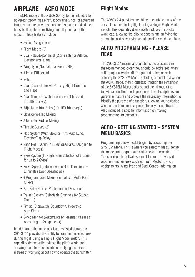
A-1
AIRPLANE – ACRO MODEThe ACRO mode of the X9503 2.4 system is intended for powered fixed-wing aircraft. It contains a host of advanced features that are easy to set up and use, and are designed to assist the pilot in realizing the full potential of the aircraft. These features include:
• Switch Assignments
• Flight Modes (3)
• Dual Rates/Exponential (2 or 3 sets for Aileron, Elevator and Rudder)
• Wing Type (Normal, Flaperon, Delta)
• Aileron Differential
• V-Tail
• Dual Channels for All Primary Flight Controls and Flaps
• Dual Throttles (With Independent Trims and Throttle Curves)
• Adjustable Trim Rates (10–100 Trim Steps)
• Elevator-to-Flap Mixing
• Aileron-to-Rudder Mixing
• Throttle Curves (2)
• Flap System (With Elevator Trim, Auto Land, Elevator/Flap Delay)
• Snap Roll System (4 Directions/Rates Assigned to Flight Modes)
• Gyro System (In-Flight Gain Selection of 3 Gains for up to 2 Gyros)
• Servo Speed (Independent in Both Directions – Eliminates Door Sequencers)
• 6 Programmable Mixers (Includes 2 Multi-Point Mixers)
• Fail-Safe (Hold or Predetermined Positions)
• Trainer System (Selectable Channels for Student Control)
• Timers (Stopwatch, Countdown, Integrated, Auto Start)
• Servo Monitor (Automatically Renames Channels According to Assignments)
In addition to the numerous features listed above, the X9503 2.4 provides the ability to combine these features during flight, using a single Flight Mode switch. This capability dramatically reduces the pilot’s work load, allowing the pilot to concentrate on flying the aircraft instead of worrying about how to operate the transmitter.
Flight Modes
The X9503 2.4 provides the ability to combine many of the above functions during flight, using a single Flight Mode switch. This capability dramatically reduces the pilot’s work load, allowing the pilot to concentrate on flying the aircraft instead of worrying about specific switch positions.
ACRO PROGRAMMING - PLEASE READ
The X9503 2.4 menus and functions are presented in the recommended order they should be addressed when setting up a new aircraft. Programming begins with entering the SYSTEM Menu, selecting a model, activating the ACRO mode, then progresses through the remainder of the SYSTEM Menu options, and then through the individual function mode programs. The descriptions are general in nature and provide the necessary information to identify the purpose of a function, allowing you to decide whether the function is appropriate for your application. Also included is specific information on making programming adjustments.
ACRO - GETTING STARTED – SYSTEM MENU BASICS
Programming a new model begins by accessing the SYSTEM Menu. This is where you select models, identify the mode and program other high-level information. You can use it to activate some of the more advanced programming features such as Flight Modes, Switch Assignments, Wing Type and Dual Control information.

ACCESS THE SYSTEM MENU RESET THE MODEL
A-2 A-3
When setting up a new model you should reset all parameters to their default or factory settings before proceeding with any other programming. This ensures there are no program mixes, trims or other functions left over from a previous model or programming session.
1. In the SYSTEM Menu, highlight and select MDL Reset using the Selector.
2. Press the CLR button that is next to RES on the display.
3. Press the lowermost button next to YES on the display to reset all data for this model.
4. Return to the SYSTEM Menu by pressing the LIST button.
To set up a new model, first select the desired model memory. Generally an unused model memory is selected. However, memory that already contains data for another model may be used, as long as data for that model is no longer required since any data in that memory will be lost.
1. In the SYSTEM Menu, highlight and select Model SEL using the Selector. The currently selected model number displays. If you want a different model, highlight and select the displayed model and a list of models will appear. Scroll up and down the list using the Selector.
2. Use the Selector to highlight and select the desired model memory.
3. Return to the SYSTEM Menu by pressing the LIST button.
1. To access the System menu [SYSTEM M.], hold down the ENT button while turning the transmitter on.
SELECT A MODEL MEMORY
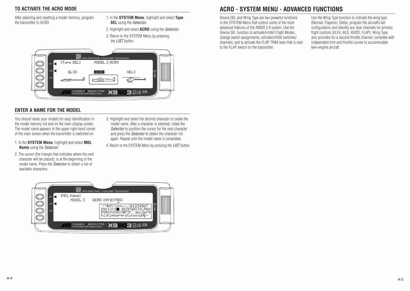
TO ACTIVATE THE ACRO MODE
ENTER A NAME FOR THE MODEL
A-4 A-5
After selecting and resetting a model memory, program the transmitter to ACRO.
1. In the SYSTEM Menu, highlight and select Type SEL using the Selector.
2. Highlight and select ACRO using the Selector.
3. Return to the SYSTEM Menu by pressing the LIST button.
You should name your models for easy identification in the model memory list and on the main display screen. The model name appears in the upper right-hand corner of the main screen when the transmitter is switched on.
1. In the SYSTEM Menu, highlight and select MDL Name using the Selector.
2. The cursor (the triangle that indicates where the next character will be placed), is at the beginning of the model name. Press the Selector to obtain a list of available characters.
3. Highlight and select the desired character to create the model name. After a character is selected, rotate the Selector to position the cursor for the next character and press the Selector to obtain the character list again. Repeat until the model name is completed.
4. Return to the SYSTEM Menu by pressing the LIST button.
Device SEL and Wing Type are two powerful functions in the SYSTEM Menu that control some of the more advanced features of the X9503 2.4 system. Use the Device SEL function to activate/inhibit Flight Modes; change switch assignments; activate/inhibit switches/channels; and to activate the FLAP TRIM lever that is next to the FLAP switch on the transmitter.
Use the Wing Type function to indicate the wing type (Normal, Flaperon, Delta); program the aircraft’s tail configuration; and identify any dual channels for primary flight controls (ELEV, AILE, RUDD, FLAP). Wing Type also provides for a second throttle channel, complete with independent trim and throttle curves to accommodate twin-engine aircraft.
ACRO - SYSTEM MENU - ADVANCED FUNCTIONS

FLIGHT MODES To Activate Flight Modes
A-6 A-7
out. A couple of program mixes can be set up to bring in some Up-Elevator to make the jet assume a positive angle of attack, and to deploy the speed brakes. The two mixers can then be assigned only to the 3rd Flight Mode for landings. The Landing flap position can also be associated with the third or Landing Flight Mode and the Gyro gain can again be turned on to assist in a straight roll-out during landing.
Many of the functions found in the X9503 2.4 system are switch selectable (including programmable mixers) and can be assigned to one or more Flight Modes. This provides the ability to have 3 completely different aircraft configurations that are selectable in flight using a single switch.
Three Flight Modes are available in the X9503 2.4 system. When activated, you can select them during flight by using one of the two 3-position switches (FLAP Switch or AUX2 switch). You decide which switch to use when Flight Modes are activated in the Devic. SEL function in the System menu. Once Flight Modes are activated, you have a choice of using the Flight Mode switch to select up to 3 Dual Rates and Exponential settings for each of the primary controls (ELEV, AILE, RUDD), or Dual Rates and Exponential settings may continue to be controlled by the 3 individual Dual Rate switches. However, when using the standard D/R switches, there are only 2 settings possible for each of the primary controls because the D/R switches are only 2-position switches. All other functions that can be activated by a switch can be assigned to 1 or more Flight Modes when Flight Modes have been activated.
Decide if Flight Modes are to be activated. If 3 sets of Dual Rates and Exponential settings are desired for Elevator, Ailerons, and Rudder instead of having only 2 sets available, then continue with the following steps to activate Flight Modes.
If you want to gang Dual Rates for Aileron, Elevator and Rudder together on a single switch, then continue with the following steps to activate Flight Modes.
If you need to group multiple functions together in order to perform certain tasks with the aircraft, then continue with the following steps to activate Flight Modes. If it is decided that Flight Modes are not to be activated, then skip to SWITCH ASSIGNMENTS.
A Flight Mode represents an aircraft configuration (Dual Rate/Expo, programmed mixes, Aileron Differential, Flap System, Gyro System, etc.) designed and optimized to assist the pilot and the aircraft in performing a specific type of maneuver.
Programming Flight Modes provides the ability to flip a switch to select a collection of settings optimized to perform a maneuver. An aerobatic aircraft, for example, may be set up such that the Flight Mode switch in its first position configures the aircraft for normal precision flying. Positioning the switch in its second position sets the aircraft up for snap rolls. Positioning the switch in its third position sets the aircraft up for consecutive rolls, slow rolls, and rolling circles. The 3 Flight Modes could just as easily represent aircraft settings for Takeoff, Flying, and Landing for a turbine-powered jet aircraft. Thus Flight Modes can make the pilot’s job easier by configuring the aircraft to do different things by flipping a single switch.
For example, let’s consider a jet aircraft. The jet will utilize 3 Flight Modes - 1 for takeoffs, 1 for flying at high speed and 1 for landing.
During takeoff, full control deflections are desired, with a moderate amount of Exponential to assist in rotation and control of the aircraft at takeoff speed. Steering should have a lot of Exponential to avoid over-steering during the takeoff roll. So for the first Flight Mode (FM0), Dual Rates and Exponential curves are set for Ailerons and Elevator to allow adequate control for rotation and control at takeoff speed, while a high percentage of Exponential is set for the rudder/steering to help prevent over-steering during takeoff. If the aircraft is equipped with 3 position Flaps (Retracted, Takeoff position and Landing position), the Takeoff flap position can be assigned to only the first Flight Mode to assist in takeoff. There may also be a Gyro attached to the steering/rudder and the Gyro gain can be turned on and associated with the Takeoff Flight Mode to assist in keeping the aircraft straight during the takeoff roll.
For normal flight at higher speeds, the second Flight Mode (FM1) would be set up to have quite a bit of Exponential and perhaps reduced control rates on all control surfaces because a lot less control deflection is required at high speeds. The retracted flap position would also be assigned to this Flight Mode and the Gyro gain could be reduced or turned off.
For landing, the third Flight Mode (FM2) would be set up to use full control throws with a moderate-to-high degree of Exponential to smoothly control the jet at lower landing speeds and again have a lot of Exponential on the rudder to prevent over-steering upon the landing/roll
1. From SYSTEM M. highlight and select Devic. SEL using the Selector.
2. Highlight and select INH under FLIGHT MODE. When selected, two options appear: AUX2 SW and FLAP SW. Highlight and select the switch you will use to select between Flight Modes while flying. The example below shows that the FLAP switch has been selected.
Once Flight Modes have been activated, 2 new parameters appear on the display: TRIM:COM and D/R:SW.
Once one of the 3-position switches is selected, Flight Mode 0 (FM0) is in effect when the switch is in the upper position. Flight Mode 1 (FM1) is in effect when the switch is in the middle position, and Flight Mode 2 (FM2) is in effect when the switch is moved to the lowest position.

TRIM:COM (Flight Modes)
D/R:SW (Flight Modes)
SWITCH ASSIGNMENTS
FLAP TRIM ON/OFF
A-8 A-9
You can toggle the TRIM:COM parameter back and forth between COM and FM by pressing the Selector when COM or FM is highlighted. If left in the COM mode, the digital trims for Elevator, Ailerons, and Rudder are Common or shared by the 3 Flight Modes. If FM is selected, the X9503 2.4 keeps track of the digital trims independently for each Flight Mode, so the pilot can re-trim the aircraft using the digital trims for each Flight Mode. This helps if switching between Flight Modes causes the aircraft’s trim to change, such as when flaps are deployed by one of the Flight Modes causing a slight roll. In this case, the pilot can simply use the Aileron digital trim to trim the Ailerons, eliminating the roll tendency when that Flight Mode is selected. Selecting other Flight Modes brings in a corresponding set of trims, ensuring the aircraft stays in trim as the pilot changes between the 3 Flight Modes during flight.
If Flight Modes are only going to be used to switch between 3 sets of Dual Rates/Exponential settings, then leave the TRIM parameter set to COM. If other functions are to be controlled by Flight Modes which may have a tendency to cause the aircraft trim to change, then select FM for the TRIM parameter. The example below shows FM selected, meaning that each Flight Mode has its own set of trims. You can change the setting at any time by returning to this display.
Note: When trims are set to FM, be especially careful during the first flight of an aircraft to remember that the aircraft will need to be trimmed using the digital trims for Aileron, Elevator and Rudder for each Flight Mode selected during flight. If the aircraft is badly out of trim, it will probably be badly out of trim for each Flight Mode selected. If the out-of-trim condition is very severe, it might be wise to land after trimming the first Flight Mode and note the trim settings. Switch to the other 2 Flight Modes and match the trims to these settings before flying again.
You can toggle the D/R:SW parameter between SW and FM by pressing the Selector when SW or FM is highlighted. If left in the SW mode, then you will use the 3 Dual Rate switches to select Dual Rates and Exponential settings for Elevator, Ailerons, and Rudder and there will only be 2 sets of Dual Rates/Expo settings for each control. If FM is selected, you will use the Flight Mode switch to select Dual Rates/Expo settings for all three controls at once (Elev, Aile, Rudd - D/R settings ganged together on the Flight Mode switch). There will be 3 sets of D/R/Expo values available for each control.
If you want individual D/R switches (3 switches) to control only 2 sets of rates and curves for Elevator, Ailerons and Rudder, set this parameter to SW. If you want 3 sets of rates and curves selectable by a single Flight Mode switch, then set this parameter to FM. You can change this setting any time by returning to this display.
The X9503 2.4 provides the ability to change the standard default switch assignments for GEAR, FLAP, AUX2, AUX3, and AUX4. You can change the standard switch assignments in the Devic.SEL function contained in the SYSTEM Menu. To change one or more switch assignments:
1. From within the Devic.SEL function, use the Selector to highlight and select GEAR, FLAP, AUX2, AUX3, or AUX4 along the top line of the display.
2. Once a switch is selected, a list of available replacement switches displays. Highlight and select the desired switch with the Selector.
3. Repeat for as many switches as desired.
1. The digital FLAP TRIM lever is located next to the FLAP switch. You can activate or deactivate it in the Devic.SEL function by using the Selector to highlight either ON or OFF and pressing the Selector to toggle between these two values.
Ordinarily this switch should be turned OFF, even if the aircraft has flaps or flaperons. The system provides other means of controlling flaps. Disabling this switch will help prevent a serious out-of-trim condition if flaperons are used and the trim lever is accidentally moved. Do not turn this on unless there is a specific need to do so.
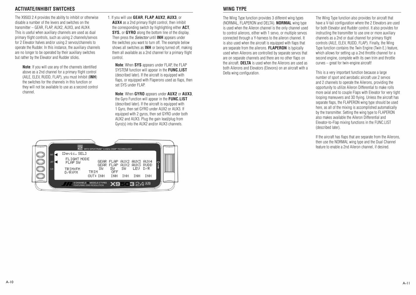
ACTIVATE/INHIBIT SWITCHES WING TYPE
A-10 A-11
The X9503 2.4 provides the ability to inhibit or otherwise disable a number of the levers and switches on the transmitter – GEAR, FLAP, AUX2, AUX3, and AUX4. This is useful when auxiliary channels are used as dual primary flight controls, such as using 2 channels/servos for 2 Elevator halves and/or using 2 servos/channels to operate the Rudder. In this instance, the auxiliary channels are no longer to be operated by their auxiliary switches but rather by the Elevator and Rudder sticks.
Note: If you will use any of the channels identified above as a 2nd channel for a primary flight control (AILE, ELEV, RUDD, FLAP), you must Inhibit (INH) the switches for the channels in this function or they will not be available to use as a second control channel.
1. If you will use GEAR, FLAP, AUX2, AUX3, or AUX4 as a 2nd primary flight control, then inhibit the corresponding switch by highlighting either ACT, SYS. or GYRO along the bottom line of the display. Then press the Selector until INH appears under the switches you want to turn off. The example below shows all switches as INH or being turned off, making them all available as a 2nd channel for a primary flight control.
Note: When SYS appears under FLAP, the FLAP SYSTEM function will appear in the FUNC.LIST (described later). If the aircraft is equipped with flaps, or equipped with Flaperons used as flaps, then set SYS under FLAP.
Note: When GYRO appears under AUX2 or AUX3, the Gyro Function will appear in the FUNC.LIST (described later). If the aircraft is equipped with 1 Gyro, then set GYRO under AUX2 or AUX3. If equipped with 2 gyros, then set GYRO under both AUX2 and AUX3. Plug the gain lead/plug from Gyro(s) into the AUX2 and/or AUX3 channels.
The Wing Type function provides 3 different wing types (NORMAL, FLAPERON and DELTA). NORMAL wing type is used when the Aileron channel is the only channel used to control ailerons, either with 1 servo, or multiple servos connected through a Y-harness to the aileron channel. It is also used when the aircraft is equipped with flaps that are separate from the ailerons. FLAPERON is typically used when Ailerons are controlled by separate servos that are on separate channels and there are no other flaps on the aircraft. DELTA is used when the Ailerons are used as both Ailerons and Elevators (Elevons) on an aircraft with a Delta wing configuration.
The Wing Type function also provides for aircraft that have a V-tail configuration where the 2 Elevators are used for both Elevator and Rudder control. It also provides for instructing the transmitter to use one or more auxiliary channels as a 2nd or dual channel for primary flight controls (AILE, ELEV, RUDD, FLAP). Finally, the Wing Type function contains the Twin Engine (Twin E.) feature, which allows for setting up a 2nd throttle channel for a second engine, complete with its own trim and throttle curves – great for twin-engine aircraft!
This is a very important function because a large number of sport and aerobatic aircraft use 2 servos and 2 channels to operate the Ailerons, providing the opportunity to utilize Aileron Differential to make rolls more axial and to couple Flaps with Elevator for very tight looping maneuvers and 3D flying. Unless the aircraft has separate flaps, the FLAPERON wing type should be used here, as all of the mixing is accomplished automatically by the transmitter. Setting the wing type to FLAPERON also makes available the Aileron Differential and Elevator-to-Flap mixing functions in the FUNC.LIST (described later).
If the aircraft has flaps that are separate from the Ailerons, then use the NORMAL wing type and the Dual Channel feature to enable a 2nd Aileron channel, if desired.
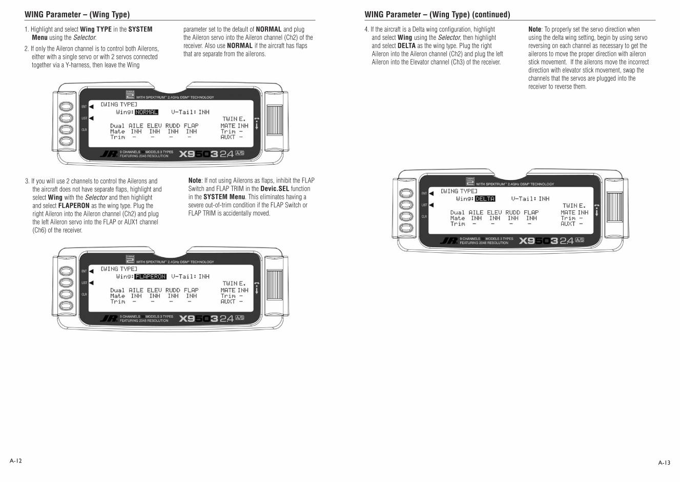
WING Parameter – (Wing Type) WING Parameter – (Wing Type) (continued)
A-12 A-13
1. Highlight and select Wing TYPE in the SYSTEM Menu using the Selector.
2. If only the Aileron channel is to control both Ailerons, either with a single servo or with 2 servos connected together via a Y-harness, then leave the Wing
3. If you will use 2 channels to control the Ailerons and the aircraft does not have separate flaps, highlight and select Wing with the Selector and then highlight and select FLAPERON as the wing type. Plug the right Aileron into the Aileron channel (Ch2) and plug the left Aileron servo into the FLAP or AUX1 channel (Ch6) of the receiver.
parameter set to the default of NORMAL and plug the Aileron servo into the Aileron channel (Ch2) of the receiver. Also use NORMAL if the aircraft has flaps that are separate from the ailerons.
Note: If not using Ailerons as flaps, inhibit the FLAP Switch and FLAP TRIM in the Devic.SEL function in the SYSTEM Menu. This eliminates having a severe out-of-trim condition if the FLAP Switch or FLAP TRIM is accidentally moved.
4. If the aircraft is a Delta wing configuration, highlight and select Wing using the Selector, then highlight and select DELTA as the wing type. Plug the right Aileron into the Aileron channel (Ch2) and plug the left Aileron into the Elevator channel (Ch3) of the receiver.
Note: To properly set the servo direction when using the delta wing setting, begin by using servo reversing on each channel as necessary to get the ailerons to move the proper direction with aileron stick movement. If the ailerons move the incorrect direction with elevator stick movement, swap the channels that the servos are plugged into the receiver to reverse them.

Dual Channels (Wing Type)
V-tail (Wing Type) V-tail (Wing Type) (continued)
A-14 A-15
1. To assign a 2nd channel to Ailerons, Elevator, Rudder or Flaps, highlight and select INH under the desired channel on the Mate line of the Wing TYPE display and a list of available channels is displayed.
Note: Channels/Switches must be inhibited (INH) in the Devic. SEL function before they appear in the list as an option to be used as a Dual channel.
1. If the aircraft has a V-tail configuration, highlight INH next to V-tail in the Wing TYPE function and press the Selector until ACT appears. Plug the right Elevator servo into the Elevator channel (Ch3) and plug the left Elevator servo into the Rudder channel (Ch4). Pressing the Selector toggles the parameter between ACT and INH. If the aircraft has a normal tail, make sure INH is selected and plug the Elevator and Rudder servos into the Elevator and Rudder channels (Ch3 and Ch4 respectively). Continue with Dual Channels below.
2. Highlight and select the channel that is to be the Mate (slave) to the control channel represented above it. Plug the 2nd control surface servo into the channel selected as the Mate.
3. If FLAP or AUX3 is selected as a Mate, INH will appear on the Trim Line of the display directly beneath the channel just selected. This means that the corresponding digital switch (FLAP TRIM or AUX TRIM) located next to the FLAP and AUX2 switches can be used as additional trim. However, the additional trims do not function in the same fashion as regular trims. Instead, they trim the controls such that both channels move in the same direction – like reflexing both Ailerons or in the case of Elevator halves, the Elevators would move in opposite directions. As a result, you should leave these additional trims inhibited unless you’ve a special need for them. If changed to ACT, the corresponding trim switch (FLAP or AUX3) will become active. If set to INH these additional trim switches are inactive. Normal trims continue to work regardless of the settings.
Note: To properly set the servo direction when using the V-tail setting, begin by using servo reversing on each channel as necessary to get the elevators to move the proper direction with rudder stick movement. If the elevators move the incorrect direction with elevator stick movement, swap the channels that the servos are plugged into in the receiver to reverse them.
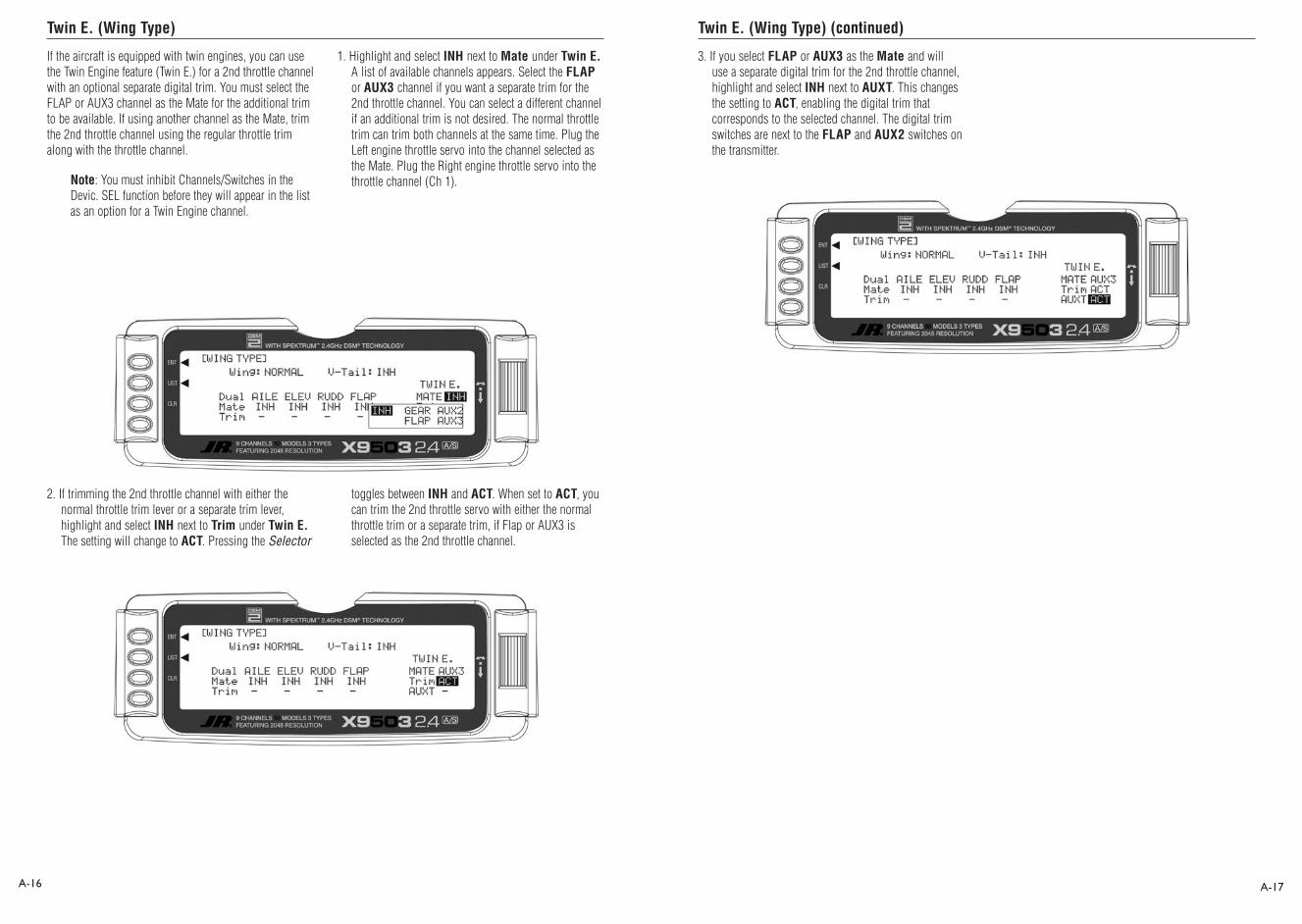
Twin E. (Wing Type) Twin E. (Wing Type) (continued)
A-16 A-17
If the aircraft is equipped with twin engines, you can use the Twin Engine feature (Twin E.) for a 2nd throttle channel with an optional separate digital trim. You must select the FLAP or AUX3 channel as the Mate for the additional trim to be available. If using another channel as the Mate, trim the 2nd throttle channel using the regular throttle trim along with the throttle channel.
Note: You must inhibit Channels/Switches in the Devic. SEL function before they will appear in the list as an option for a Twin Engine channel.
1. Highlight and select INH next to Mate under Twin E. A list of available channels appears. Select the FLAP or AUX3 channel if you want a separate trim for the 2nd throttle channel. You can select a different channel if an additional trim is not desired. The normal throttle trim can trim both channels at the same time. Plug the Left engine throttle servo into the channel selected as the Mate. Plug the Right engine throttle servo into the throttle channel (Ch 1).
2. If trimming the 2nd throttle channel with either the normal throttle trim lever or a separate trim lever, highlight and select INH next to Trim under Twin E. The setting will change to ACT. Pressing the Selector
toggles between INH and ACT. When set to ACT, you can trim the 2nd throttle servo with either the normal throttle trim or a separate trim, if Flap or AUX3 is selected as the 2nd throttle channel.
3. If you select FLAP or AUX3 as the Mate and will use a separate digital trim for the 2nd throttle channel, highlight and select INH next to AUXT. This changes the setting to ACT, enabling the digital trim that corresponds to the selected channel. The digital trim switches are next to the FLAP and AUX2 switches on the transmitter.

TRIM STEP
REV.SW – SERVO REVERSING
A-18 A-19
The Trim Step function adjusts the sensitivity of the X9503 2.4 trim levers and switches. It allows quick initial trimming of the aircraft, then makes precise adjustments to aircraft trim after that. The digital trims may have a setting of 0–10 with 10 being the coarsest adjustment. When the value is set to 10, there are only 10 trim increments from center to each end. When set to 5, there are 20 trim increments from center to each end. When set to 4 there are 25 increments. When set to 3 there are 34 increments and when set to 1 there are 100 trim increments! When set to 0 the trim levers cease to function and cannot change the trim of the aircraft.
When adjusting the digital trims (AILE, ELEV, RUDD, FLAP, AUXT), the total trim travel does not change. Only the number of increments (beeps) changes, which makes for finer or coarser trim movements. When adjusting the analog throttle trim, however, the total trim travel is actually reduced when set to less than 100%.
Use a fairly coarse setting such as 4–6 when test flying an aircraft in order to trim the aircraft quickly. Then use a finer setting such as 3–1 for final precision trimming.
1. Highlight and select TRIM STEP in the SYSTEM MENU to acquire the TRIM STEP display.
2. Highlight and select the trim you are changing. Use the Selector to set a value of 1–10 (1 = finest, 10 = coarsest).
3. Repeat for other trims as desired.
This concludes the SYSTEM Menu portion of the ACRO mode. Continue with FUNC.LIST to complete the aircraft setup.
After defining the basic aircraft configuration in the SYSTEM Menu, use the functions in the Function List [FUNCT.LIST] to complete the setup and adjust how the aircraft flies. We present the functions (to the extent practical) in the order they should be addressed when setting up a new aircraft.
The descriptions are general in nature and are intended to provide enough information to decide whether or not to use a function and what types of selections and settings to make.
Press the LIST button after the transmitter is powered up to obtain the FUNC.LIST.
After plugging all servos into their proper channels in the receiver, the first thing to check is the direction of travel of each servo’s travel. Move all sticks and switches/levers while observing each servo to determine if the servos are moving in the correct directions. Make note of those channels not traveling in the correct direction and use the REV.SW function to reverse the direction of travel for these channels.
1. Highlight and select REV.SW in the FUNC.LIST to obtain the servo reversing display.
2. Use the Selector to highlight and select those channels that need to be reversed. Pressing the Selector toggles the channel between Normal and Reverse.
ACRO – FUNCTION LIST

Sub-Trim TRVL ADJ. – TRAVEL ADJUST
A-20 A-21
Use Sub-Trims for minor adjustments to servo linkages, not for major trim adjustments to the aircraft. Using excessive Sub-Trim percentages can cause a loss of available servo travel where the servo reaches its travel limit and stops moving before the control sticks are fully deflected. For more information on Sub-Trims and linkage setups, refer to the Sub-Trim Usage and Mechanical Advantage article in the Glossary.
Use Sub-Trims to fine-tune the alignment of servo arms. Install servo arms on the servos so that the arms are at 90˚ or perpendicular to the servo case/linkage. Rotate, swap and reinstall the arms or try different arms if necessary to get them as close to 90˚ as possible. It is not unusual for the arms to be off just a little bit. Now use the Sub-Trim function to fine-tune the servo arms that are not quite at 90˚ to the linkage/servo case.
1. Highlight and select Sub-Trim in the FUNC.LIST to obtain the Sub-Trim Display.
2. Highlight and select the channels where the servo arms are not quite at 90˚ to the servo cases. Once a channel is selected, rotate the Selector until the servo arm is at 90˚ to the servo case.
Use Travel Adjust to calibrate how far a servo travels in each direction. After installing the linkages and attaching to the servos, adjust the amount of servo travel in each direction. For more information on Servo Travel and Mechanical Advantage, refer to the Sub-Trim Usage and Mechanical Advantage article in the Glossary.
1. Highlight and select TRVL ADJ. in the FUNC.LIST to obtain the Travel Adjust display.
2. Use the Selector to highlight and select each channel and adjust the travel in each direction by rotating the Selector. The direction of travel is changed by moving the stick/switch/lever back and forth.

D/R & EXP – DUAL RATE AND EXPONENTIAL THRO CURV – THROTTLE CURVE
A-22 A-23
Dual Rates and Exponential curves can be very effective in setting up an aircraft to have a particular “feel” when performing different types of maneuvers. Just flipping a switch can change the aircraft’s personality, causing it to take on traits that make certain maneuvers easier for the pilot. At times the aircraft needs to feel very crisp, such as when performing point-oriented aerobatics, and then feel softer for other maneuvers such as landing and rolling circles. At other times the aircraft needs to be very crisp but without the tendency to be over-controlled, like in performing snap rolls. You can combine Dual Rates and Exponential curves to produce these traits for most any aircraft. When programming a Dual Rate and Exponential curve, think about what kind of maneuver you will perform
and your desired response from the aircraft. For an in-depth description of D/R and Exponential, please refer to the Dual Rates and Exponential Curves at the end of the Aircraft section of this manual
1. Highlight and select D/R & EXP in the FUNC.LIST to obtain the D/R & EXP display. If you activated Flight Modes earlier in the Devic.SEL function and set D/R to FM in the same function, 3 sets of values will display for each channel. Otherwise, there will only be 2 sets of Dual Rate and Exponential settings for each control.
2. Use the Selector to change between Aileron, Elevator and Rudder by highlighting and selecting AILE. Then use it to select and set dual rate and exponential values. If exponential has never been used before, try a low positive value like +10. After a while increase it gradually until the desired feel is obtained.
Note: Use only positive (+) percentages unless there is a distinct need to do otherwise.
A linear throttle response can be obtained with the THRO CURV function by causing the throttle servo to move in an exponential fashion. In other words, the servo will move very little for the first ¼–½ of stick movement, and then move more rapidly as the stick is advanced further.
You can also use THRO CURV to set up a special throttle response where the engine quickly comes up to a certain rpm, then advances very slowly to provide precise rpm control for a specific throttle range before continuing on to full throttle. Such a curve is useful for torque rolling, rolling circles and other maneuvers where the throttle response is slowed or flattened-out for a particular throttle range.
If you activated the Twin E. function for twin-engine aircraft, independent throttle curves are available for each engine to help eliminate any discrepancies in the throttle response between the two engines.
If the aircraft is equipped with an engine that has a non-linear response, set up a throttle curve as described below.
1. Highlight and select THRO CURV in the FUNC.LIST. Two different throttle curves may be defined and they are named or otherwise referenced by Pos0 and Pos1.
2. If there is a need to have 2 throttle curves (e.g. a regular curve and a curve for torque rolling), use the Selector to highlight SW SELECT and a list of available Flight Modes and switches appears. Select the Flight Mode(s) (FM0, FM1, or FM2) and/or switch(es) used to select between the 2 curves. The switch will be used to select between the Pos0 curve and the Pos1 curve. Highlight and select Pos0 to toggle between the Pos0 and Pos1, in order to display and adjust the 2 curves.

THRO CURV – THROTTLE CURVE (continued) FLAP SYS. – FLAP SYSTEM
A-24 A-25
3. Scroll over to OFF under EXP and select it to turn exponential ON. This smoothes out the throttle curve.
4. Scroll over to Point-3 and select it. Set the Point-3 value to 25%. This yields a preliminary throttle curve that provides a good starting point for further adjustments. The remainder of the adjustments should be made with the engine running and the aircraft securely restrained so that it cannot possibly move.
Note: If you activated Twin E. for a twin engine aircraft, there will be a Pos0 and Pos1 for both the right and left engines, providing a total of 4 possible throttle curves.
5. Warm up the engine to its normal operating temperature. Move the throttle stick to full idle and slowly advance the throttle 1 click at a time. There should be a noticeable change in rpm for each movement of the stick. If while moving the stick it seems that the engine should be running faster or slower for a given throttle stick position, select the point closest to the vertical line (cursor) and increase the value if the engine is running too slow or decrease the value if the engine is running too fast for the stick position. Repeat as necessary until the desired response is obtained.
However, instead of being named Pos0 & Pos1, they are named RTH.0, RTH.1, LTH.0, and LTH.1. They represent Right Throttle Pos0 & Pos1 and Left Throttle Pos0 & Pos1 respectively.
The X9503 2.4 features a three-position Flap System with Elevator compensation, programmable Delay, and an Auto Land feature. Its purpose is to allow the flaps to be deployed in two different positions in addition to the normal or fully retracted position. The Flap System is available in the FUNC.LIST only if SYS. is selected on the OUT line under FLAP in the Devic. SEL function within the SYSTEM Menu.
Because deploying flaps generally causes a change in pitch (Elevator trim), the Flap System provides for setting an Elevator deflection for each flap position. This is called Elevator Compensation. There is also a programmable Delay in .1 second increments up to a maximum of 2 seconds. The Delay determines how long it takes for the Flaps and Elevator to reach their positions. The X9503 2.4 ensures that the Flaps and Elevator reach their positions at the same time resulting in smooth Flap deployment and retraction.

AUTO LAND (Flap System) ELEV – ELEVATOR COMPENSATION (Flap System)
A-26 A-27
1. If using Auto Land, scroll to INH under AUTO LAND and select it with the Selector. INH will change to ACT when selected and toggles between ACT and INH each time the Selector is pressed.
The Auto Land feature, if implemented, automatically retracts the Flaps and Elevator compensation when the throttle is raised above a specified throttle position. This can be useful during a missed landing approach when a go-around is required. The Flap System allows the Flaps to be deployed using the Flap Switch, Flight Mode switch or a combination of both.
2. Scroll down to THRO and press the Selector to show the throttle percentage. Rotate the selector until the throttle percentage (0–100%) is equal to where the Auto Land feature is to retract the Flaps and Elevator compensation.
You should set the throttle position very high at first (between 90–99%) to give the aircraft a chance to regain some speed before the Flaps actually retract. As the Flaps retract, lift will decrease and the stall speed of the aircraft will increase and may cause a crash if the airspeed is too low. When there is a missed approach, advance the throttle slowly up to about 90% and wait until the aircraft picks up some speed before advancing the throttle to full, causing the Flaps to retract.
Highlight and select FLAP SYS. in the FUNC.LIST to obtain the Flap System display if the aircraft has flaps or Flaperons that are also going to be used as flaps.
The ELEV values represent the Elevator deflection that occurs when the Flaps are deployed to their various positions. Some trial and error will probably be required to arrive at the right values, but once set, the aircraft will assume the proper pitch attitude for all flap positions.
1. Make sure the NORM value next to ELEV is set to 0% as there should be no Elevator deflection with the flaps in their fully retracted (up) position. If it is not 0%, scroll to NORM next to ELEV, select it, and then set the value to 0%.
2. Scroll to the Mid parameter beside ELEV and select it. Set the value either U (up) or D (down) to introduce up or down Elevator trim for the Mid position of the flaps. If not sure about which direction, aircraft typically pitch up when flaps are deployed, requiring some Down Elevator input to compensate. Use a small percentage like 3–5% at first and, after test flying, adjust the value a little at a time until the aircraft maintains the correct pitch attitude (typically slightly nose down) when the flaps are deployed to the Mid position.
3. Scroll to the Land parameter beside ELEV on the display and press the Selector to select it. Set the value either U (up) or D (down) to introduce a small amount (5–10%) of up or down Elevator for the Land position of the flaps, in the same fashion as setting up the Mid position above.

FLAP – (Flap System) FM0-FM2 (Flap System)
A-28 A-29
The FLAP values represent how far the flaps deflect when in the NORM, Mid, and Land positions. The NORM position represents normal flying where the flaps are fully retracted. The Mid position is typically used for short field takeoffs and the Land position is typically used for landing. Refer to the aircraft manufacturer’s specifications for recommended flap deflections.
1. Put the Flap switch in its uppermost (Normal) position (no flaps deployed). Scroll to the NORM parameter next to FLAP on the display. It should be at U100%. If it is not, select it with the Selector and set it to 100% or the value that brings the flaps up to their normal flying position (no flaps deployed) with the Flap switch in the uppermost or Normal position.
2. Put the Flap switch in Mid position. Scroll to the Mid parameter next to FLAP on the display and select it. Dial in a Down percentage to deflect the flaps downward the desired amount. The example above shows a value of 25%, but you should follow the aircraft manufacturer’s specifications to set this value to achieve the recommended partial flap deflection.
3. Put the Flap switch in the lowermost or Land position. Scroll to the Land parameter next to FLAP on the display and select it. Dial in a Down percentage to deflect the flaps downward the amount required for landing. The illustration below shows a value of 80%, but you should use the aircraft manufacturer’s specifications to set this value to achieve the recommended deflection.
If Flight Modes have been activated in the Devic. SEL function of the SYSTEM Menu then FM0, FM1 and FM2 appear along the right side of the Flap System display to represent the 3 Flight Modes. You can assign each of the Flight modes one of the Flap Values (NORM, Mid, or Land), so when that Flight Mode is selected during flight, the Flaps deploy to that position. SW is also an option. When you select SW or a Flight Mode, the Flap switch controls flap operation in that Flight Mode.
If Flight Modes have not been activated, skip this portion of the Flap System.
1. For each Flight Mode, highlight and select FM0-FM2 and select either a flap position (NORM, Mid, Land) that the flaps assume when in that Flight Mode, or select SW if the Flap switch controls the flaps when in that Flight Mode.
The example above shows Flight Mode 0 (FM0) set to SW, meaning the Flap switch controls flaps when in this Flight Mode. With FM1 set to Mid, the flaps deflect to the Mid position when Flight Mode 1 is selected. With FM2 set to Land, the flaps deploy to the Land position when Flight Mode 2 is selected.

Delay (Flap System) ELEFLP M – ELEVATOR-TO-FLAP MIXING
A-30 A-31
The Delay parameter determines how long it takes for the flaps and Elevator to reach their positions. The X9503 2.4 automatically times the Flaps and Elevator so they reach their positions at the same time. This allows smooth Flap deployment and retraction. You can adjust the Delay in .1-second increments up to a maximum of 2 seconds.
1. Highlight and select Delay in the Flap System display using the Selector. Then use the rotary to select a delay between .1 second and 2.0 seconds.
The X9503 2.4 features a built-in mixer for Elevator-to-Flap. The mixer causes the Flaps (or Flaperons) to move when the Elevator is moved, resulting in tighter looping maneuvers, or to provide some Aileron reflex for some 3D maneuvers such as harriers. Typically, the flaps are set to travel downward with up Elevator and upward with down Elevator. The exception is adding reflex for 3D maneuvers such as harriers. In this case the reverse is set so the
flaps travel up with up elevator and down with down elevator. You can change the direction the flaps travel with Elevator input using positive and negative values.
If Elevator-to-Flap mixing is desired for the aircraft, perform the steps below.
1. Highlight and select ELEFLP M in the FUNC.LIST to obtain the Elevator-to-Flap mix display.
2. There are 2 sets of mixing values available – Pos0 or Pos1. If the Pos0 values are left at 0% then the mixer may be turned on and off – Pos0 will be OFF and Pos1 will be ON (this can be reversed by leaving the Pos1 values at zero and putting values in Pos0). Highlight and select DN next to Pos1 and set the value to give the desired amount of Flap travel in the Down direction when full Up Elevator is applied.
3. Highlight and select UP next to Pos1 and set the value to give the desired amount of Flap travel in the UP direction when full Down Elevator is applied.
4. Scroll down to the bottom line of the display to select the Flight Mode(s) and/or switch(es) used to turn the mixer on and off. You can also turn the mixer on and off with the throttle by highlighting and selecting THRO STK. Set the percentage of throttle to the point where the mixer is to switch between on and off.
Note: Pos1 always has priority over Pos0. If multiple switches are selected to turn the mixer on and off and one of the switches is in its Pos1 position, all other switches are ignored and the Pos1 values are in effect.

AILRUD M – AILERON-TO-RUDDER MIXING AIL DIFF. – AILERON DIFFERENTIAL
A-32 A-33
The X9503 2.4 features a built-in mixer for Aileron-to-Rudder. The mixer causes the Rudder to deflect when the Ailerons are moved resulting in coordinated turns. This is a useful function for high-wing aircraft with flat-bottomed airfoils because the Ailerons are typically not very effective, and Rudder input combined with Aileron input dramatically improves the turn and bank authority for these aircraft. The Rudder normally moves in the same direction as the Ailerons, however, the Rudder can
be made to move in either direction by using positive or negative values.
If the aircraft requires Aileron-to-Rudder mixing, perform the steps below.
1. Highlight and select AILRUD M in the FUNC.LIST to obtain the Aileron-to-Rudder mix display.
2. There are 2 sets of mixing values available – Pos0 and Pos1. If the Pos0 values are left at 0% then the mixer may be turned on and off – Pos0 would be off and Pos1 would be on (this can be reversed by leaving the Pos1 values at zero and putting values into Pos0). Highlight and select L next to Pos1 and set the value to give the desired amount of Left Rudder. A negative value will reverse the direction.
3. Highlight and select R next to Pos1 and set the value to give the desired amount of Right Rudder. A negative value will reverse the direction.
4. Scroll down to the bottom line of the display to select the Flight Mode and/or switch(es) used to turn the mixer on and off. The example below shows Flight Mode 2 set to Pos1, turning on the Aileron-to-Rudder mix. The throttle may also be used to turn the mixer on and off by highlighting and selecting THRO STK and setting the percentage of throttle to the point where the mixer is switched on/off.
Note: You can also set the Pos0 values to something other than zero for a different amount of Rudder deflection upon Aileron input. You can then select one or more switches to switch between the two sets of values. With this setup there will always be some mixing, as indicated by either Pos0 or Pos1, and the mixing cannot be turned off.
Note: Pos1 always has priority over Pos0. If you select multiple switches to turn the mixer on and off and one of the switches is in its Pos1 position, all other switches are ignored and the Pos1 values are in effect.
When Ailerons are deflected, the Aileron that deflects downward typically creates more drag than the Aileron that deflects upward. If the difference in drag is great enough, the aircraft will yaw in the direction of the down Aileron. For example a roll to the right causes the aircraft to yaw to the left because the left Aileron deflects downward and creates more drag. This, of course, is an undesirable tendency that results in non-axial rolls and a loss of heading.
The X9503 2.4 provides an Aileron Differential function that allows adjustment of the Aileron deflecting downward without affecting the Aileron that travels upward eliminating yaw tendencies in rolling maneuvers. It can also affect only the Aileron that travels upward (negative differential). This is useful if an aircraft yaws in the same direction as the Aileron input.
Aileron differential is available in the FUNC.LIST only if the FLAPERON Wing Type was selected in the Wing Type function in the SYSTEM Menu or a Dual channel was assigned to ailerons in the Wing TYPE function.
The Aileron Differential function provides for 2 differential settings that are switch or Flight Mode selectable – Pos0 and Pos1. You can combine the 2 settings in different ways to provide one setting that is on all the time, or one setting on and one off (0 differential). It could also provide 2 different amounts of differential like one for normal flying and another for flat spins.
To use the Aileron Differential function, highlight and select AIL Diff. in the FUNC.LIST to obtain the Aileron Differential display.
1. To program a single Aileron differential setting that is on all the time, highlight and select Pos0 and set a small percentage of differential. A positive value causes the downward Aileron to travel less while a negative value causes the upward Aileron to travel less (negative differential). Test fly the aircraft and return to this function to make adjustments until the yaw tendency has been eliminated. That is all that is required to set up a single differential setting that is always on.

AIL DIFF. – AILERON DIFFERENTIAL (continued) SRV.SPEED – SERVO SPEED
A-34 A-35
2. If using 2 Aileron differential values you can select a switch to control the differential amount and set each position as desired. If one of these values is set to zero, Aileron differential can be turned off by selecting the position that has the 0 values. Highlight and select Pos0 and set a small percentage of differential or leave it set to zero (0) if the ability to turn differential
off is desired. Highlight and select Pos1 and set the percentage of differential. A positive value causes the downward Aileron to travel less, while a negative value causes the upward Aileron to travel less (negative differential). The example below shows a positive percentage in Pos0 for precision flying and a negative differential for Pos1 for flat spins, which is selectable with Flight Mode 2 (FM2).
3. Scroll down to the bottom line of the display to select the Flight Mode and/or switch(es) that will switch between the Aileron Differential settings. You can also use the throttle to switch between differential settings by highlighting and selecting THRO STK and setting the percentage of throttle to the point where the values are switched. Test fly the aircraft and return to this function to make adjustments until eliminating the yaw tendency.
Note: Pos1 always has priority over Pos0. If you select multiple switches and one of the switches is in its Pos1 position, then all other switches are ignored and the Pos1 values are in effect.
The X9503 2.4 system provides the ability to adjust the speed of servos on each channel in both directions. The speed may be adjusted downward (servo slowed) from its normal speed but it cannot cause a servo to move faster than its rated specifications. Furthermore, each servo can have 2 sets of speeds in both directions that are Flight Mode or switch selectable.
The servo speed function is very useful for scale models with retractable landing gear and gear doors, since in many instances the need for gear door sequencers can be eliminated. If the gear door servos move at normal speed and the landing gear servos move at a slower speed when the gear is lowered, the gear doors will be open before the landing gear begins to come down. In the opposite direction, if the gear door servos move slowly and the landing gear servos move at normal speed, the gear can retract before the gear doors begin to close.
Note: Most mechanical retract servos are non-proportional type servos that simply move from endpoint to endpoint. These types of servos are not adjustable in the servo speed function.
Servo speed can also be useful on the throttle channel. The throttle servo can be slowed down such that the engine will not flame out because the carburetor is opened or closed too quickly when the throttle stick is jammed from low to high and vice versa.
To adjust servo speed, highlight and select SRV.Speed in the FUNC.LIST.
1. If there is to be a single set of servo speeds in effect all of the time, make sure the display is showing Pos0. If it is not, select Pos1 and change it to Pos0.
Highlight and select the channel and direction for each servo you will adjust. Once a direction for a servo is selected, the servo speed may be set so the servo travels from .176 seconds for 60 degrees of rotation all the way up to 15 seconds for 60 degrees of rotation. Adjust the speed of each servo until the desired speed is obtained. The example below shows the throttle servo slowed down so that it traverses 60 degrees in 1.25 seconds in both directions. That is all that is required when there is only 1 set of servo speeds.
2. If using 2 sets of servo speeds that are Flight Mode or switch selectable, you can select a switch to control the servo speed and set each position as desired. If one set of values is set to NORM for all channels, slowing of servos can be turned off by selecting the position (Pos0 or Pos1) that has the NORM values. Highlight and select Pos0 and change it to Pos1 then highlight and select the channel and direction for each servo you will adjust. Once a direction for a servo is selected, the servo speed may be set so the servo travels from .176 seconds for 60 degrees of rotation all the way up to 15 seconds for 60 degrees of rotation. Adjust the speed of each servo until the desired speed is obtained. Highlight and select Pos0 then highlight and select the channel and direction for each servo that is to be adjusted. Switch between Pos0 and Pos1 to view and adjust the 2 sets of values for each servo.
3. Scroll over to and select SW SELECT to identify
the Flight Mode and/or switch(es) used to switch between the 2 sets of servo speeds. The throttle may also be used to switch between differential settings by highlighting and selecting THRO STK and setting the percentage of throttle to the point where the values are switched.
Note: Pos1 always has priority over Pos0. If you select multiple switches and one of the switches is in its Pos1 position, then all other switches are ignored and the Pos1 values are in effect.
The X9503 2.4 has a Snap Roll system comprised of a

SNAP ROLL GYRO SYS. – GYRO SYSTEM
GYRO CONNECTIONS (Gyro System)
A-36 A-37
Snap Roll switch used in conjunction with Flight Modes to select a direction (Right/Up, Right/Down, Left/Up, and Left/Down) and deflections for Aileron, Elevator and Rudder. You can program up to four directions and corresponding rates and assign a Direction/Rate combination to 1 or more of the 3 Flight Modes. Pressing the Snap Roll switch causes the aircraft to snap roll in the direction and according to the rates assigned to the Flight Mode currently selected.
If you activate Flight Modes you can assign 3 of the Snap Roll directions/rates to them—one per Flight Mode. If you haven’t activated Flight Modes then only one of the directions/rates may be active and it must be set/selected in the Snap Roll function. The Snap Roll function is inhibited as a default and must be turned on in order to use it.
If using the Snap Roll function, highlight and select Snap
Roll in the FUNC.LIST, then select INH to activate it.
1. If you activated Flight Modes in the Devic. SEL function, FM0, FM1, and FM2 appear down the left hand side of the display. Select each one and assign a direction (RIGHT-DOWN, RIGHT-UP, LEFT-DOWN, LEFT-UP) from the list for each of the 3 Flight Modes.
If Flight Modes are not activated, only a single direction appears along the left-hand side of the display. Highlight and select it and pick one of the directions.
2. Scroll over to the AILE deflection of the first direction (R-D) and set it to a rather high percentage. Scroll down to the ELEV deflection for the same direction and set it to a modest value of perhaps 40% to prevent “burying” the aircraft with too much Elevator during the snap. Now scroll down to the RUDD deflection and set it to a modest value like the Elevator.
3. Repeat step 2 for the other 3 directions.
The X9503 2.4 features a very sophisticated Gyro Gain Sensitivity System allowing in-flight selection of 3 gyro gains for two separate gyros. It provides for fixed gain values as well as a Stick Override Gain, where gyro gain is progressively reduced as the stick is moved further off center. Stick Override Gain is an absolute “must” for controlling gyros in aerobatic aircraft.
Note: In order for the GYRO System to appear in the FUNC.LIST, you must set the AUX2 and/or the AUX3 channels to GYRO on the OUT Line of the Devic.SEL display. If neither of these are set to GYRO, then GYRO System does not appear as a function in the FUNC.LIST.
You can use up to 2 gyros to control two of the three primary flight controls (Elevator, Rudder, or Aileron). Typical applications involve gyros on the Rudder and/or Elevator. You can use the FLAP and/or AUX2 switch to switch between the 3 different gains for each gyro. You can also control the gyro gains by Flight Modes. They can be fixed or variable using the Stick Override Gain feature. If you set one set of gains for each gyro to zero, then the gain/gyro can essentially be switched off during flight.
Note: Use this function only with gyros that have in-flight proportional gain adjustment capability. Single and dual rate gyros that use a potentiometer to adjust the gain will not work properly with this function.
Plug the gain connector of one gyro into the AUX2 port of the receiver. Plug the gain connector of another gyro (if any) into the AUX3 of the receiver. If using only one gyro, connect its gain to either AUX2 or AUX3.
Note: You must set the OUT line at the bottom of the Devic.SEL function to GYRO for AUX2 and/or AUX3 if using them to control Gyros.

FIXED GYRO GAIN (Gyro System) STICK OVERRIDE GYRO GAIN (Gyro System)
A-38 A-39
Fixed Gyro Gain does not use the Stick Override Gain feature. Whichever of the 3 gains you select to remain in effect moving the control stick does not affect the gain.
1. To access the GYRO System, highlight and select GYRO SYS. in the FUNC.LIST.
AUX2 gain settings appear in the top half of the display while the AUX3 settings appear in the lower half of the display. They will appear only if AUX2 and/or AUX3 have been set to GYRO on the OUT line of the Devic.SEL function.
2. Decide which switch will control gyro gain. The Flap switch and the AUX2 switch are the only 3-position switches the Gyro System can use. You can use one switch to select the gain for both gyros, or each gyro can use a different switch to select the gain. Typically, one switch is used to control the gain, even when 2 gyros are used.
Highlight and select AX2 SW or FLP SW next to AUX2 and AUX3 until the desired switch is displayed next to each. The example below shows the AUX2 switch selected for both gyros.
3. Each gyro has 3 possible gain settings. They are labeled 0, 1, and 2 next to CEN on the display, with a percentage next to each (CEN stands for gyro gain when the control stick is at center – no stick deflection). They correspond to the positions of a 3-position switch where 0 represents the switch being in the upper position; 1 represents the middle position; and 2 represents the lower position. We recommend that the 0 position (upper switch position) for each gyro be set to zero (0%) which allows the gyro to be turned off in flight (very useful if a gyro suddenly becomes overly sensitive).
4. Use the Selector to highlight and select the number 0 position for each gyro and set the percentage to 0% if not already at a 0% value.
5. Select the number 1 gain for each gyro and set it to some moderate value. The example shows 50% gain set for both gyros.
6. Select the number 2 gain for each gyro and set it to a relatively high value. The example shows 85% gain set for both gyros.
7. If Flight Modes have not been activated, skip to the next step.
If Flight Modes have been activated in the Devic. SEL function, a list of Flight Modes (FM0, FM1, FM2) displays to the right of the display for each active Gyro. The default setting for each Flight Mode is S, indicating that the 3-position gyro switch will control the gyro gain when in that Flight Mode. You can change the S to 0, 1, or 2 to represent the gain values associated with the positions of the 3-position switch. For example, if FM1 is set to 0, then when in Flight Mode 1, the gain is 0% which corresponds to the gain of the upper position of the 3-position switch. If FM1 is set to 1, the gain is 50%, and if FM1 is set to 2, the gain is 85% when in Flight Mode 1.
Highlight and select each FM parameter and set it to S, 0, 1, or 2 to indicate if the Gyro switch will control gyro gain while in that Flight Mode, or to assign one of the gains to the flight Mode. The example above shows all Flight Modes as deferring gyro gain control to the 3-position gyro gain switch – in this case the AUX2 switch.
8. This completes the Fixed Gyro Gain setup. In the example, the AUX2 switch selects the gain of both gyros at the same time. The upper position of the switch selects 0%, essentially turning the gyros off. The middle position selects 50% for both gyros and the lower position selects 85% gain for both gyros. The selected gain does not change when the sticks are moved.
Stick Override Gyro Gain is very popular with aerobatic pilots, as it allows the pilot to instantaneously override the gyro by moving the stick. Gyro gain decreases as the stick is moved further from neutral and is typically set up so that gyro gain is reduced to zero when the stick is at full deflection. When the stick is released and allowed to center, gyro gain is instantaneously restored. In other words, the pilot assumes control of the channel by moving the stick and returns control of the channel to the gyro by releasing the stick. This helps in performing excellent hammerheads/stall turns, as the gyro is overridden by the Rudder stick in performing the pivot, but instantly dampens out any “wiggle” as soon as the pivot is completed and the Rudder stick released.
Stick Override Gyro Gain is identical to Fixed Gyro Gain in all regards except that the control stick(s) progressively reduces the presently selected gyro gain as the stick(s) is moved off of center. As mentioned before, it is typically set up so that when the stick reaches full deflection, the gyro gain is reduced to zero.
1. To access the Stick Override Gyro Gain feature, highlight and select GYRO SYS. in the FUNC.LIST.
2. Perform all of the steps outlined for Fixed Gyro Gain above.
3. Scroll over to and select STICK for each gyro and select the stick that corresponds with the control surface being controlled by the gyro. For example, if AUX2 is controlling the gain for the Rudder gyro, select RUDD as the stick for AUX2. If AUX3 is controlling the gyro for Elevator, select ELEV as the stick for AUX3.
4. Once a stick has been selected, a new set of END percentages appears on the display—all with a value of 50%. These new percentages indicate the gyro gain when the stick is moved to full deflection. If set to 0%, the gain will be progressively reduced as the stick is moved off center until it reaches 0% when the stick is at full deflection.
It is recommended that all END percentages be set to 0% unless there is a specific need to do otherwise. The default value of all END percentages is 50%. Use the Selector to highlight and select each END percentage and set each one to 0%.

PROG MIX – PROGRAMMABLE MIXERS STANDARD PROGRAMMABLE MIXER – Example: DOWN ELEVATOR AT IDLE
A-40 A-41
The X9503 2.4 System provides 4 Standard programmable mixers (PROG.MIX3 - PROG.MIX6) and 2 Multi-Point programmable mixers (PROG.MIX1 & PROG.MIX2). Mixing occurs when the pilot moves a stick, switch or lever on the Master channel and the transmitter generates an input for the Slave channel. The Slave’s input is based on the pilot’s input to the Master channel and the parameter defined in the programmable mixer.
You can use programmable mixers whenever you want a channel to react or move (Slave) by providing input to another channel (Master), or to move a channel by moving a switch or lever. They are typically used to compensate for deficiencies in aircraft design/setup, such as eliminating pitch- and roll-coupling in knife-edge flight, and to activate special aircraft functions like smoke systems, speed brakes, bomb drops, idle-up, etc.
Multi-Point Mixing provides the ability to define a customized “curve” of travel that the Slave channel will follow as it reacts to the Master channel. It is different from Normal Mixing in the sense that Normal Mixing results in a linear movement of the Slave channel in relation to the Master. With Multi-Point Mixing there are 7 points (including endpoints) along the travel of the Master channel that can be adjusted to control the action of the Slave channel (more or less travel in the same/opposite direction) providing the ability to deviate from a linear mixing action.
Mixes are programmable, allowing any of the 9 channels to be Master, Slave or both. Additionally there are 4 options for Master channels that begin with a “#” (pound sign), these Master channels are origin type mixes. These include #THR, #AIL, #ELE, and #RUD. Origin mixing bypasses any other mixing that might affect that channel such as throttle curves or other programming and uses the stick position only to control the mix. Also the Master channel can be assigned to one of the two digital rocker switches, levers, or button. If dual functions have been activated in the device select function, it is possible for the Slave channel to be assigned to channels such as AILV, FPRN, FROL, and RUDV. These functions allow the ailerons to be moved as flaps, flaps to be moved as ailerons, elevators to be moved as ailerons, rudders to be moved as speed brakes either both in or both out, or similar functions.
Some examples of how programmable mixers might be used include but are certainly not limited to:
• Eliminate Roll-Coupling where the aircraft rolls when there is Rudder input. The mixer causes the Ailerons to move just a little bit in the opposite
direction of the Rudder in order to keep the aircraft from rolling, while holding Rudder for knife-edge flight. This standard mixer would designate the Rudder as the Master and the Ailerons as the Slave.
• Eliminate Pitch-Coupling where the aircraft pitches to the gear or canopy when holding Rudder for knife-edge flight. The mixer causes the Elevator to move a little when Rudder is applied to keep the aircraft from pitching while holding Rudder during knife-edge flight. This Multi-Point mixer would designate the Rudder as the Master and the Elevator as the slave. A Multi-Point mixer would be used because pitch-coupling is typically non-linear in nature and requires a customized curve to counteract pitching induced by different amounts of Rudder deflection.
• Eliminate pulling out on down lines where the aircraft has a tendency to pull out towards the canopy when flying vertical down lines at idle. The mixer generates a bit of down Elevator when the throttle stick is pulled back to idle, making the aircraft track straight down with no input from the pilot. This mixer would designate the Throttle as the Master and the Elevator as the Slave and would be turned on and off with a switch so the down Elevator would not be generated during landing.
• Controlling a Smoke System where a switch activates a smoke system. The smoke system comes on when the throttle stick is advanced beyond a certain point. This standard mixer would designate Throttle as the Master and an Auxiliary channel as a slave and would be turned on and off by a switch.
• Idle-Up where flipping a switch causes the engine rpm to increase a bit at idle to protect against a flameout during flying, then return to low idle for landing. This standard mixer would designate an auxiliary channel as the Master and the Throttle channel as the Slave. It would also use a switch to turn the mixer on and off.
The possibilities are endless and limited only by the imagination.
Perhaps the best way to describe a Programmable Mixer is by example. The example below demonstrates a program mix for an aircraft that pulls out or pitches towards the canopy when trying to fly a vertical down line at idle. If a mix is set up to provide a couple of degrees of down Elevator when at idle, the aircraft will track straight down without input from the pilot. Once the throttle is advanced above idle, the mixer is turned off and the down Elevator is removed. The mixer can also be turned off so the down Elevator input does not occur during landing.
This mixer uses the Throttle as the Master and the Elevator as the Slave. The mix is turned on and off with the GEAR switch in combination with the position of the throttle stick – ON at idle and OFF above idle with the GEAR switch ON. When the GEAR switch is OFF, the mixer is turned off regardless of throttle setting.
The Mix parameters will be selected and set in the following order: Program Mix number, Master, Slave, Switch, Travel/Direction, and Offset. This is generally a good sequence to follow when setting up Programmable Mixers.
1. Program Mix Number. Highlight and select one of the Standard Programmable Mixers (PROG.MIX3 - PROG.MIX6) to obtain the first Programmable Mix display. Then press ACT next to CLR or highlight and select INH to obtain the main mix display. The example uses PROG.MIX3.
2. Select Master. All Programmable Mixers default to Throttle as both the Master and the Slave (THROTHRO). The first THRO is the Master and the 2nd THRO represents the Slave.
Highlight and select the first THRO to the left of the arrow to obtain a list of channels that can be used as the Master. Highlight and select the #THR channel as the Master, bypassing any throttle curve settings. This causes the physical position of the throttle stick to control the mixer.
3. Select Slave. Highlight and select THRO to the right of the arrow to obtain a list of channels that can be used as the Slave. Highlight and select ELEV as the Slave.
4. Select Switch. Scroll down, highlight, and select GER as the switch that turns the mixer on and off. The GER indicator should appear in the upper or Pos1 position at the bottom of the display. You can use any of the switches along the bottom of the display as well as multiple switches. The example is using only the Gear switch.
5. Select Switch Position. Move the Gear switch back and forth while observing the number directly to the right of the Program Mix Name in the upper left hand corner of the display. The number will change from 0 to 1 as the switch is moved back and forth. When the number is 0, the mixer is looking at the Pos0 values (not programmed yet) and when it is a 1, it is looking at the Pos1 values (also not programmed yet).Put the switch in the position that turns the mixer ON. Look at the number directly to the right of the Program Mix Name. If it is 0, highlight and select Pos0 on the display. If it is 1, highlight and select Pos1 on the display. The example shows Pos0 as the position to turn the mixer ON.
6. Travel and Direction. With the switch still in the ON position, move the throttle stick to the full low position and the lower value next to the selected position should be highlighted. Set the lower position parameter to a low positive value like +3%. This is the amount of deflection of the Elevator (Slave channel) occurring when the mixer is turned on and the throttle is reduced to idle, or just enough to see a little down elevator deflection.
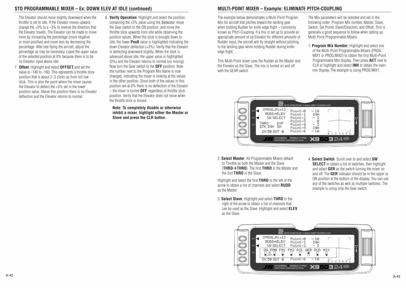
STD PROGRAMMABLE MIXER – Ex: DOWN ELEV AT IDLE (continued) MULTI-POINT MIXER – Example: ELIMINATE PITCH-COUPLING
A-42 A-43
The Elevator should move slightly downward when the throttle is set to idle. If the Elevator moves upward, change the +3% to a –3% to reverse the direction that the Elevator travels. The Elevator can be made to move more by increasing the percentage (more negative or more positive) and move less by decreasing the percentage. After test flying the aircraft, adjust the percentage as may be necessary. Leave the upper value of the selected position at 0% because there is to be no Elevator input above idle.
7. Offset. Highlight and select OFFSET and set the value to -140 to -160. This represents a throttle stick position that is about 2–3 clicks up from full low stick. This is also the point where the mixer causes the Elevator to deflect the +3% set in the lower position value. Above this position there is no Elevator deflection and the Elevator returns to normal.
8. Verify Operation. Highlight and select the position containing the +3% value using the Selector, move the Gear switch to the ON position, and move the throttle stick upwards from idle while observing the position values. When the stick is brought down to idle, the lower Pos0 value is highlighted indicating the down Elevator deflection (+3%). Verify that the Elevator is deflecting downward slightly. When the stick is advanced above idle, the upper value is highlighted (0%) and the Elevator returns to normal (no mixing). Now turn the Gear switch to the OFF position. Note the number next to the Program Mix Name is now changed, indicating the mixer is looking at the values in the other position. Since both of the values in this position are at 0% there is no deflection of the Elevator – the mixer is turned OFF regardless of throttle stick position. Verify that the Elevator does not move when the throttle stick is moved.
Note: To completely disable or otherwise inhibit a mixer, highlight either the Master or Slave and press the CLR button.
The example below demonstrates a Multi-Point Program Mix for aircraft that pitches toward the landing gear when holding Rudder for knife-edge flight – commonly known as Pitch-Coupling. If a mix is set up to provide an appropriate amount of up Elevator for different amounts of Rudder input, the aircraft will fly straight without pitching to the landing gear while holding Rudder during knife-edge flight.
This Multi-Point mixer uses the Rudder as the Master and the Elevator as the Slave. The mix is turned on and off with the GEAR switch.
The Mix parameters will be selected and set in the following order: Program Mix number, Master, Slave, Switch, Set Points Travel/Direction, and Offset. This is generally a good sequence to follow when setting up Multi-Point Programmable Mixers.
1. Program Mix Number. Highlight and select one of the Multi-Point Programmable Mixers (PROG.MIX1 or PROG.MIX2) to obtain the first Multi-Point Programmable Mix display. Then press ACT next to CLR or highlight and select INH to obtain the main mix display. The example is using PROG.MIX1.
2. Select Master. All Programmable Mixers default to Throttle as both the Master and the Slave (THROTHRO). The first THRO is the Master and the 2nd THRO is the Slave.
Highlight and select the first THRO to the left of the arrow to obtain a list of channels and select RUDD as the Master.
3. Select Slave. Highlight and select THRO to the right of the arrow to obtain a list of channels that can be used as the Slave. Highlight and select ELEV as the Slave.
4. Select Switch. Scroll over to and select SW SELECT to obtain a list of switches, then highlight and select GER as the switch turning the mixer on and off. The GER indicator should be in the upper or ON position at the bottom of the display. You can use any of the switches as well as multiple switches. The example is using only the Gear switch.

MULTI-POINT MIXER – Ex: ELIMINATE PITCH-COUPLING (continued) TRAINER – TRAINER SYSTEM
X9503 USED AS MASTER (INSTRUCTOR) – (Trainer System)
A-44 A-45
5. Set Points for Travel and Direction. There are 7 points along the travel of the Rudder (the line intersected by the vertical line that moves right and left with the Rudder stick). At each point an Elevator deflection may be defined. A point that is set to 0% represents no Elevator deflection at that point. A negative value at a point typically indicates Up Elevator movement while a positive value results in Down Elevator movement. A point set to INH takes on the value of the curve/line between the 2 adjacent points. The direction of travel may be reversed (Up Elevator vs. Down Elevator) by changing values from negative (-) to positive (+) (moving the point values above and below the 0% line).
Since the aircraft pitches to the landing gear with the application of both Right and Left Rudder, the Elevator deflection will be zero at center (Point-3) (no mixing). At the points either side of Point-3 will be negative, indicating Up Elevator movement. The more negative a point value, the more Up Elevator deflection. Set the points initially to the following values.
Point-0 - 10% (At full Right Rudder the Elevator will deflect
Up 10%)Point-1 INH (Takes on the value along the curve between
Point-0 & Point-2)Point-2 -3% (Elevator deflects Up 3% when Rudder is
moved to Point-2)Point-3 0% (no Mixing – no Elevator deflection when
Rudder is at neutral)Point-4 -3% (Elevator deflects Up 3% when Rudder is
moved to Point-4)Point-5 INH (Takes on the value along the curve between
Point-4 & Point-6)Point-6 -10% (At full Left Rudder the Elevator will deflect
Up 10%)
6. Offset. Point-3 represents the offset position and corresponds to the Rudder stick being at neutral. It is important to leave Point-3 set at 0% to make sure there is no mixing and therefore no Elevator deflection when the Rudder is at neutral.
7. Verify Operation. Turn the Receiver on and turn the mix on using the Gear switch. Move the Rudder stick from full right to full left. The Elevator should deflect Up when the Rudder is moved in both directions. If it moves down instead, change the percentages to (+) values instead of (-) values at each point. If the Elevator appears to be moving too much, reduce the point values (less negative). If the Elevator does not seem to move enough, then increase the point values (more negative). Now turn the Gear switch to the OFF position and verify that the Elevator does not move.
While test flying the aircraft, make note of the mixing and whether it generates enough up-Elevator during knife-edge to stop it from pitching to the gear, or generating too much Elevator input, causing it to pitch to the canopy instead of the gear. Also note the approximate position of the Rudder stick when pitching occurs. Land the aircraft and adjust the points closest to the position of the Rudder stick when pitching occurs for more or less Elevator deflection until the aircraft no longer pitches during knife-edge. More negative generates more Up Elevator and less negative generates less Up Elevator. Points 1 and 5 may be activated and their value changed if necessary to fine-tune the mix.
Note: To completely disable or otherwise inhibit a mixer, highlight either the Master or Slave and press the CLR button.
The X9503 2.4 contains a Trainer System that allows the instructor to transfer some or all of the primary flight control functions (Throttle, Aileron, Elevator and Rudder) to the student. It also allows you to indicate if the transmitter is the Master (controlled by the instructor) or Slave (controlled by the student). The Snap Roll button transfers control to the student when the X9503 2.4 is being used as the Master/Instructor transmitter.
All Dual rates and Exponential settings in the Master transmitter are transferred to the Slave transmitter when the master transmitter channels are selected individually in the trainer menu. The Slave transmitter battery must be charged.
1. Connect the Trainer cord between the Master and Slave transmitters. Turn the power on to the Master transmitter. (The Slave transmitter remains powered off and can even have the module removed if equipped with a module)
2. Make sure the Slave transmitter is in the PPM/FM modulation mode. If the slave system is a X9503 2.4, or any other system that is Spread Spectrum only, such as other JR 2.4GHz or Spektrum systems, this does not apply.
3. Highlight and select Trainer in the FUNC.LIST to obtain the Trainer Display.
1. If the X9503 2.4 is the Master transmitter select the channel(s) operated by the Slave transmitter when the trainer switch is depressed.
When all channel selectors are in the MAST position, NORMAL appears on the display and all 4 channels are transferred to the student when the trainer switch is depressed. When all channel selectors are in the MAST position, the slave system must be programmed for the model, meaning all programming necessary for the model must be programmed in both the master and the slave systems. Also when all the channel selectors are in the MAST position, the slave system should be left in normal default MASTER mode.
To transfer only certain channels to the student, highlight and select the channels you will transfer, moving the indicator for these channels to the SLAV position for these channels. When less than all channels are selected as SLAV, PROGRAM T appears on the display indicating that the Trainer System has been programmed
to transfer only selected channels. When the channel selectors are in the SLAV position, all programming of the master system will be used, and only the stick movements of the 4 primary channels are used from the slave system when control is given to the slave transmitter. In this case, the slave system does not need to be programmed for the model. Also the slave system should be set to Slave mode in it’s trainer system.
The X9503 2.4 is now ready to be used as the Master or instructor transmitter. Depress the Snap Roll button to transfer control to the student. Control will remain transferred until the Snap Roll button is released.

X9503 2.4 USED AS SLAVE (STUDENT) – (Trainer System) TIMER – TIMER SYSTEM
A-46 A-47
Highlight and select MASTER and the display will switch to SLAVE. A message appears instructing to Connect DSC & POWER off. Make sure the transmitter power switch is in the Off position and the trainer cord is connected between the 2 transmitters.
If the master system is an XP9303, X9303 2.4, X9503 2.4, or 12X and the individual channels are not selected in the master system’s trainer function, leave the slave system’s
The X9503 2.4 contains a Timer System that contains two timers. One is an integrated timer that keeps track of total time that the transmitter has been on for the model and appears on the Main display. The other timer can be configured as either a Countdown timer or as a Stopwatch. This timer also appears on the Main display when active and can be started, stopped and reset from the Main display. It is a good idea to use the Countdown timer as a reminder that it is time to land so as not to run out of fuel.
If using the Countdown timer, an Auto Start function is available that starts the timer when the throttle is raised over 20% the first time after the transmitter is turned on.
1. To configure the timer as a Countdown timer highlight and select Timer in the FUNC.LIST to obtain the Timer display.
Highlight and select INH under TIMER then select DOWN-T. Use the Selector to set the countdown start time. Once the timer is set, TIM will appear on the Main display in the lower left corner. Pressing the button next to TIM on the Main display starts and stops the timer while pressing the button next to CLR resets the timer to the programmed value.
2. To Reset the Integrated Timer, highlight and select the time under INTEG-T and Push[CLR]=0:00 appears on the display. Press the CLR button to the left of the display to reset the Integrated timer. If the momentary button or switch is not used for another function, it can also be used to start and stop the timer.
trainer function in the default MASTER setting. In this case, both the master and the slave systems must be fully programmed and set up to fly the model including all servo reversing, travel adjust, program mixes and all other necessary programming.
The X9503 2.4 is now ready to be used as the Slave or student transmitter.
3. If the Auto Start function is desired which starts the timer by the throttle stick, select INH next to STICK and select this to ACT. With this set to ACT, the Auto Start function will start the timer when the throttle stick is raised above 20%.
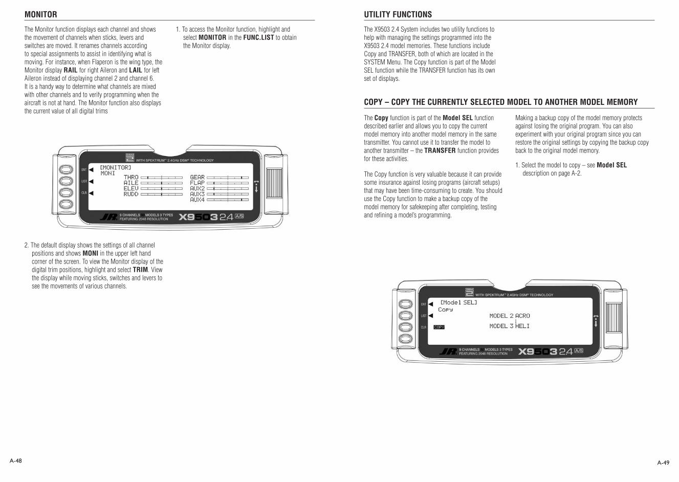
MONITOR UTILITY FUNCTIONS
COPY – COPY THE CURRENTLY SELECTED MODEL TO ANOTHER MODEL MEMORY
A-48 A-49
The Monitor function displays each channel and shows the movement of channels when sticks, levers and switches are moved. It renames channels according to special assignments to assist in identifying what is moving. For instance, when Flaperon is the wing type, the Monitor display RAIL for right Aileron and LAIL for left Aileron instead of displaying channel 2 and channel 6. It is a handy way to determine what channels are mixed with other channels and to verify programming when the aircraft is not at hand. The Monitor function also displays the current value of all digital trims
1. To access the Monitor function, highlight and select MONITOR in the FUNC.LIST to obtain the Monitor display.
2. The default display shows the settings of all channel positions and shows MONI in the upper left hand corner of the screen. To view the Monitor display of the digital trim positions, highlight and select TRIM. View the display while moving sticks, switches and levers to see the movements of various channels.
The Copy function is part of the Model SEL function described earlier and allows you to copy the current model memory into another model memory in the same transmitter. You cannot use it to transfer the model to another transmitter – the TRANSFER function provides for these activities.
The Copy function is very valuable because it can provide some insurance against losing programs (aircraft setups) that may have been time-consuming to create. You should use the Copy function to make a backup copy of the model memory for safekeeping after completing, testing and refining a model’s programming.
Making a backup copy of the model memory protects against losing the original program. You can also experiment with your original program since you can restore the original settings by copying the backup copy back to the original model memory.
1. Select the model to copy – see Model SEL description on page A-2.
The X9503 2.4 System includes two utility functions to help with managing the settings programmed into the X9503 2.4 model memories. These functions include Copy and TRANSFER, both of which are located in the SYSTEM Menu. The Copy function is part of the Model SEL function while the TRANSFER function has its own set of displays.

COPY – COPY CURRENT MODEL (continued) TRANSFER – TRANSFER THE MODEL TO ANOTHER TRANSMITTER
RECEIVE A MODEL INTO THE X9503 2.4 – (Transfer function)
A-50 A-51
2. Highlight and select Model SEL in the SYSTEM Menu. Then highlight and select Select to obtain the Copy display.
3. Verify that the top model is the model you want to back-up and the lower model is empty or no longer required. When satisfied that all is correct, press the CLR button on the left side of the display next to COPY. The entire contents of the currently selected model copy to the lower model on the display making a complete backup of the current model. The upper and lower model memory names are now the same since the two model memories are identical.
You can use the backup copy to restore the original any time. To do this, perform the Copy function reversing the order of models copying the backup to the original (backup copy on the top line and the original model memory on the bottom line).
Note: Since the X9503 2.4 has the ModelMatch feature, to operate the receiver on a new model number, you must first re-bind the receiver to the new model for it to function.
The display shows the currently selected model on top with a down-arrow pointing to the lower model memory that the current model will be copied into. The data presently in the lower model memory will be entirely replaced by the data in the currently selected model, so be sure the lower model memory is either empty or contains data no longer required.
To change the lower model memory that will receive the copy of the current model, highlight and select the lower model name and number. Scroll to an unused model memory or a memory that contains data no longer required, and select it.
1. Hold the ENT button while plugging the trainer cord into the back of the transmitter to obtain the SYSTEM Menu.
Plug the other end of the trainer cord into another X9503 2.4 transmitter while holding the ENT button down and prepare that transmitter to Receive (described below).
2. Highlight and select TRANSFER in the SYSTEM Menu to obtain the Transfer display.
The TRANSFER function is in the SYSTEM Menu and can copy the contents of a model memory to another X9503 2.4 transmitter. It is also used to receive data for a model, from another X9503 2.4 transmitter.
3. The model you will transfer must be the currently selected model. If the model to be transferred is not currently selected, see Model SEL in the SYSTEM Menu to select the model.
4. When the receiving device is ready, press the CLR button next to START on the left side of the display. The data for the currently selected model transfers to the receiving device.

RECEIVE A MODEL INTO THE X9503 2.4 – (Transfer function) Sub-Trim USAGE AND MECHANICAL ADVANTAGE
MECHANICAL ADVANTAGE
Sub-Trim
A-52 A-53
1. Hold the ENT button while plugging the trainer cord into the back of the transmitter to obtain the SYSTEM Menu. Plug the other end of the trainer cord into another X9503 2.4 transmitter while holding the ENT button and prepare that transmitter for Transmit as
described above.
2. Highlight and select TRANSFER in the SYSTEM Menu to obtain the Transfer display.
3. If RECEIVE is already displayed, continue with the next step. If TRANSMIT is displayed, highlight and select TRANSMIT, changing it to RECEIVE.
4. Select the model memory to receive the data by highlighting and selecting the model name/memory number. Then scroll to and select the model memory that will receive the data. Be careful to select an unused model memory or a model memory no longer needed as the data in this model memory will be replaced and permanently lost.
5. Press the CLR button next to START on the left side
of the display. Stand-by appears at the bottom of the display indicating that the X9503 2.4 is ready to receive data. Press start on the transmitting X9503 2.4 to begin the data transfer to the X9503 2.4.
Sub-Trims are intended for minor adjustments to servo linkages and not for major trim adjustments to the aircraft. Using excessive Sub-Trim percentages can cause a loss in servo travel in one direction, where the servo reaches its travel limit and stops moving before the control stick is fully deflected.
The diagram below illustrates an ideal servo/linkage setup when the servo is at neutral (no Sub-Trim and digital trims centered). Notice that the servo arm is positioned at 90˚ or perpendicular to the servo. Also note that the linkage or rod is attached at 90˚ to both the servo arm and the control surface horn. This setup results in the same amount of throw in both directions (0 differential throw). If you can’t mount the servo parallel to the linkage/rod, make sure the servo arm is at 90 degrees to the control rod when the servo is at neutral.
Mechanical Advantage is a very important concept when dealing with larger aircraft. It refers to the leverage that the servo can exert on the control surface. Since the control surfaces are rather large, it is important for the servo to have enough mechanical advantage or leverage to control them, regardless of the servo’s rated torque. A large amount of torque is of little value if there is not enough leverage to use it. Insufficient leverage can lead to control surface flutter (usually a catastrophic event) and blow-back, where the air flow pushes the control surface backwards resulting in mushy or no control at higher speeds.
There are two ways to increase the mechanical advantage of the servo. One is to make sure the control horn device, whether it be a horn as shown in the illustration above or a bolt with a ball-link fastener, is long enough. The horn is the lever the servo uses to control the surface. The longer the horn, the more leverage the servo has.
The second way to increase the mechanical advantage of the servo is to attach the linkage at the servo arm as far inward (toward the servo arm retaining screw) as possible while still providing enough throw. This takes leverage away from the control surface by providing it with a shorter lever to work against the servo.
Ensure that the attach point is the same distance from the hinge line for like surfaces (two Ailerons, two Elevators and two Rudder horns). If the attach points are not the same distance from the hinge line there will be unequal throw and it will be more difficult to synchronize the surfaces for equal deflection. This is especially critical for the Rudder where two servos are attached to the same surface – unequal throw will cause the servos to fight one another causing excessive battery drain, and in severe cases may cause servo damage.
Always try to use the maximum amount of Travel (100%) the radio provides. Don’t reduce the percentage of travel in the radio. Instead, move the linkage further away from the hinge line at the control surface and/or move the linkage inward on the servo arm or use a shorter arm. If you use high percentages of travel, you maintain resolution (fine movements of the stick result in fine positive movements of the control surface).
Linkage is 90 degrees to control horn
Linkage is 90 degrees to servo arm
Servo arm is 90 degrees to servo
Greater Mechanical Advantage
Greater Mechanical Advantage

DUAL RATES AND EXPONENTIAL CURVES Setup Sheet (Aircraft)
A-54 A-55
Dual Rates and Exponential curves can be very effective in setting up an aircraft to “feel” the way you would like it to feel when performing different types of maneuvers. You can essentially change the aircraft’s personality just by flipping a switch, causing the aircraft to take on traits that make certain maneuvers easier for the pilot. At times you may want the aircraft to feel very crisp, such as when performing point rolls and sided-loops and then feel softer for other maneuvers, such as rolling circles and consecutive rolls. And yet other times when you would like the aircraft to be very crisp but without the tendency to be over-controlled, like in performing snap rolls. Dual Rates and Exponential curves can be combined to produce these traits for most any aircraft. When programming a Dual Rate and Exponential curve, always think about what kind of maneuver or flying style you plan to accomplish with it.
Dual Rates (D/R) limit how far a control surface travels. Without dual rates your control surfaces deflect to their full travel – the travel that you previously established with the TRVL ADJ. function and linkage setup. When a D/R is programmed, it limits the amount of deflection that occurs when the stick is moved to its extremes. For example, if you set an Elevator D/R to 75%, the Elevator will only deflect 75% or 3/4 of its full travel; if set to 50%, it will be limited to ½ of its full travel; and so forth. A D/R setting of 100% results in full travel again, as though there were no D/R programmed at all.
An example of programming a D/R for the Ailerons would be to set up an Aileron D/R for flying consecutive rolls by setting the Aileron D/R to 25% (actual percentage will vary). At this setting, moving the Aileron stick full left or full right would result in a roll rate of about 1 roll per second. This allows you to deflect the Aileron stick all the way and just hold it there while concentrating on Elevator and Rudder inputs – flying consecutive rolls just became easier.
EXPONENTIAL (EXP) does not limit the total deflection of a servo/control surface – the surface still moves 100% of its travel. It does, however, determine how the surface reaches its full travel, or how the control surface moves relative to the stick. When Exponential is not used, the servo response is said to be linear. That is, every movement of the stick causes the same movement in the servo--if the stick moves 20%, the servo moves 20% and the control surface follows the stick throughout the entire travel range. When plotted on a graph where the X-axis (left and right) = stick movement and the Y-axis (up and down) = servo movement, the result is a straight line that is at 45 degrees.
When using Exponential, a positive (+) exponential percentage causes the servo to move less when the stick is close to the neutral point, and to move more as the stick moves further from the neutral point. For instance, the stick is moved from neutral to 30% and the servo only moves from neutral to 10%. As the stick is moved further from center (from 30% to 50%), the servo moves further and faster (from 10% to 35%). The further the stick is moved away from center, the higher the rate of servo movement. The larger the positive (+) Exponential percentage, the further the stick must be moved from center before the servo rate increases, and the faster the servo rate becomes when it gets close to the end of its travel. When stick travel (left and right) versus servo travel (up and down) is plotted on a graph, the result is a “curve.” The curve stays close to the X-axis at the center (small servo movement) and moves away from the X-axis at a greater rate (more servo movement) as the stick is moved further off center.
Exponential typically reduces sensitivity or otherwise dampens movements around the neutral stick position without sacrificing full servo travel. This provides the pilot with very smooth and precise control of the aircraft while allowing relatively large movements in the control stick. It becomes easier to make very smooth and precise corrections that are difficult to detect.
If negative exponential is used, it has the opposite effect. Servo travel increases around center and slows towards the ends. Care must be taken with negative exponential, as an aircraft that is already overly sensitive may become uncontrollable with negative exponential. It can prove useful, however, when hovering a 3D-type aircraft.
MODEL NO
MODEL NAME
SPOI AIL1 ELEV RUDD AIL2 FLAP AUX2 AUX3
REVERSE SW
SUB-TRIM
TRAVEL ADJUST
AILE ELEV RUDD
DUAL RATE/EXP
0
1
D/R
EXP
D/R
EXP
%
%
%
%
%
%
%
%
%
%
%
%
DIFFERENTIAL %
NORMREV
NORMREV
NORMREV
NORMREV
NORMREV
NORMREV
NORMREV
NORMREV
+ %
- %
L %
R %
U %
D %
L %
R %
+ %
- %
+ %
- %
L %
R %
U %
D %
PROGRAMMABLEMIX
MIX1
MIX1
MIX1
MIX1
MIX1
MIX1
CHANNEL SW EXP 0 1 2 3 4 5 6
ON/OFF
+POS -POS OFFSET
ON/OFF
ACT
INHSNAP ROLL
R-D
R-U
L-D
L-U
%
%
%
%
%
%
%
%
%
%
%
%
TRIM OFFSET
AUTO RUDD D/R ACT INH
ELEV FLAP
MIX
DOWN
UP
%
%
AILE RUDD
MIX
RATE
SW
%
%
ACT INH
ELEV
FLAP
SPOI
AUTO
LANDING
THRO
WING TYPENORMAL
FLAPERONDELTA
ADDITIONALNOTES
No Exponential
Exponential

A-56
X9503 2.4 Helicopter – Heli Mode
Heli PROGRAMMING - PLEASE READ
HELI - GETTING STARTED – SYSTEM MENU BASICS
H-1
INTRODUCTION
The Heli mode of the X9503 2.4 system is intended for use in model helicopters with all types of Swashplate mixing. It contains a host of advanced features that are easy to set up and use. The features have been designed to assist the pilot in realizing the full potential of the helicopter. These features include:
• Switch Assignments for Specific Channels/Functions
• Flight Modes (up to 6)
• Dual Rates/Exponential (up to 3 settings each for Aileron, Elevator and Rudder)
• Swashplate Type (Normal, 120, 140, and 90 CCPM)
• Adjustable Trim Rates (10 – 100 Trim Steps)
• Built-In Cyclic-to-Throttle Mixing for Aileron, Elevator, and Rudder
• Governor Pre-Program Mix
• Throttle Curves (up to 5) with up to 7 Points
• Pitch Curves (up to 6) with up to 7 Points
• Gyro System (In Flight Gain Selection of up to 3 Gains)
• 6 Programmable Mixes (Includes 2 Multi-Point and 4 Standard Mixes)
• Fail-Safe (Hold or Predetermined Positions)
•Trainer System (Selectable Channels for Student Control)
• Timers (Stopwatch, Count-Down, Integrated)
• Servo Monitor (Automatically Renames Channels According to Assignments)
In addition, the X9503 2.4 allows you to combine, activate, and deactivate multiple features such as Dual Rates, Gyro Gain, and Governor settings, using the Flight Mode switch. This capability dramatically reduces your workload, allowing you to focus on the task of flying.
Even if you’re comfortable with programming, you should still read this part of the manual to get a basic understanding of the X9503 2.4.
This section begins with entering the System Menu, selecting a model and activating the HELI Mode, and progresses through the remainder of the System Menu options and then through the individual functions. The descriptions here are general in nature and serve to identify the available functions, why they are included and when a particular function should be used.
Those who have some experience with computer radios will probably be able to program their helicopter as they read through this section, as individual functions are generally simple and the X9503 2.4 is very intuitive.
Getting started begins with accessing the SYSTEM Menu. This is where you select models, identify modes, indicate modulation type and store other high-level information for the model. You can also activate some of the more advanced programming features such as Swashplate Types and Governor Program activation.

Copy – Copying the Currently Selected Model to Another Model MemoryACCESS THE SYSTEM MENU
Model SEL- Model Selection
H-2 H-3
The Copy function is part of the Model SEL function and allows you to copy the current model memory into another model memory in the same transmitter. It is not used to transfer the model to another transmitter or to a Data Safe unit – the DATA TRANSFER function provides for these activities.
The Copy function can provide some insurance against losing programs (helicopter setups) that may have been very time-consuming to create. You should use the Copy function to make a backup copy of the model memory after you have completed, tested and refined the programming.
Making a backup copy protects you from losing the original program while allowing you to experiment with the original program. You can restore the original settings by copying the backup copy back to the original model memory.
1. Select the model to copy – see Model SEL description at the beginning of the HELI section.
2. Highlight and select Model SEL in the SYSTEM Menu. Highlight and select Select to obtain the Copy display.
The display shows the currently selected model on top with a down arrow pointing to the lower model memory that the current model will be copied into. The data in the lower model memory will be entirely replaced by the data in the currently selected model, so be sure the lower model is either empty or contains data no longer required.
To set up a new model, first select the desired model. Generally, an unused model memory is selected. However, you can use a model containing data for another
model, as long as you no longer need the data, as any information in that memory will be lost.
1. Bring up the SYSTEM Menu by holding down the ENT button while turning the transmitter on.
1. In the SYSTEM Menu, highlight and select Model SEL using the Selector.
2. Use the Selector to highlight and select the desired model number.
3. Return to the SYSTEM Menu by pressing the LIST button.

Data Reset – RESET THE MODELCopy (continued)
H-4 H-5
When setting up a new mode, reset all parameters to their default or factory settings before proceeding with any other programming. This ensures there are no programming elements left from a previous model or programming session.
If you are setting up a model for the first time, you can skip this step and move to the TYPE SELECT function.
1. In the SYSTEM Menu, highlight and select MDL Reset using the Selector.
2. Press the CLR button next to RES on the display.
3. Press the lowermost button next to YES on the display to reset all data for this model.
4. Return to the SYSTEM Menu by pressing the LIST button.
3. Verify the top model is the model you will back up and the lower model is empty or no longer needed. Then press the CLR button on the left side of the display next to COPY. The entire contents of the currently selected model copy to the lower model on the display and there is now a complete backup of the current model. The upper and lower model memory names are now the same because they are identical.
.
You can use the backup copy to restore the original any time by performing the Copy function and reversing the order of models copying the backup into the original.
Note: As the X9503 2.4 has the ModelMatch feature, in order to operate the receiver on a new model number, you must first re-bind the receiver to the new model in order for it to function.
To change the lower model memory that will receive the copy of the current model, highlight and select the lower model name and number. Then scroll to an unused model memory or a memory containing data no longer needed, and select it.

Type Select – TO ACTIVATE HELI MODE
MDL Name-ENTER A NAME FOR THE MODEL
TRANSFER A MODEL FROM THE X9503 2.4 – (Transfer function) – To Send
TRANSFER – TRANSFER THE MODEL TO ANOTHER TRANSMITTER
H-6 H-7
1. In the SYSTEM Menu, highlight and select Type SEL using the Selector.
2. Highlight and select HELI using the Selector.
You should give each model a name for easy identification in the model number list and the current model on the main display screen.
3. Return to the SYSTEM Menu by pressing the LIST button.
1. In the SYSTEM Menu, highlight and select MDL Name using the Selector.
2. Highlight and select the desired characters to form the model name.
After selecting and resetting the desired model number to program, you need to activtate Heli Mode.
3. Return to the SYSTEM Menu by pressing the LIST button.
1. Hold the ENT button while plugging the trainer cord into the back of the transmitter to obtain the SYSTEM Menu. Plug the other end of the trainer cord into another X9503 2.4 transmitter while holding the ENT button down and prepare that transmitter for Receive as described below.
2. Highlight and select TRANSFER in the SYSTEM Menu to show the Transfer display.
3. Make sure the model to be transferred is the currently selected model. If it is not selected, see Model SEL in the SYSTEM Menu to select the model to be transferred to another JR X9503 2.4.
You can use the TRANSFER function (in the System Menu) to copy the contents of a model memory to another X9503 2.4. It can also receive data for a model from another X9503 2.4 transmitter.
.
4. When the receiving device is ready, press the CLR button next to START on the left side of the display. The data for the currently selected model is transferred to the receiving device.
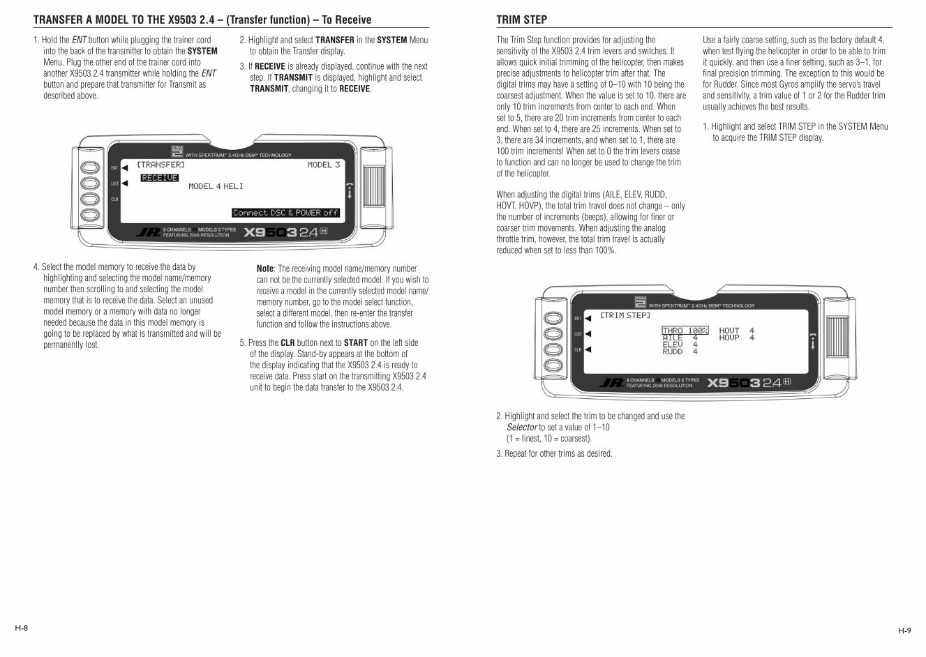
TRANSFER A MODEL TO THE X9503 2.4 – (Transfer function) – To Receive TRIM STEP
H-8 H-9
1. Hold the ENT button while plugging the trainer cord into the back of the transmitter to obtain the SYSTEM Menu. Plug the other end of the trainer cord into another X9503 2.4 transmitter while holding the ENT button and prepare that transmitter for Transmit as described above.
2. Highlight and select TRANSFER in the SYSTEM Menu to obtain the Transfer display.
3. If RECEIVE is already displayed, continue with the next step. If TRANSMIT is displayed, highlight and select TRANSMIT, changing it to RECEIVE.
4. Select the model memory to receive the data by highlighting and selecting the model name/memory number then scrolling to and selecting the model memory that is to receive the data. Select an unused model memory or a memory with data no longer needed because the data in this model memory is going to be replaced by what is transmitted and will be permanently lost.
Note: The receiving model name/memory number can not be the currently selected model. If you wish to receive a model in the currently selected model name/memory number, go to the model select function, select a different model, then re-enter the transfer function and follow the instructions above.
5. Press the CLR button next to START on the left side of the display. Stand-by appears at the bottom of the display indicating that the X9503 2.4 is ready to receive data. Press start on the transmitting X9503 2.4 unit to begin the data transfer to the X9503 2.4.
The Trim Step function provides for adjusting the sensitivity of the X9503 2.4 trim levers and switches. It allows quick initial trimming of the helicopter, then makes precise adjustments to helicopter trim after that. The digital trims may have a setting of 0–10 with 10 being the coarsest adjustment. When the value is set to 10, there are only 10 trim increments from center to each end. When set to 5, there are 20 trim increments from center to each end. When set to 4, there are 25 increments. When set to 3, there are 34 increments, and when set to 1, there are 100 trim increments! When set to 0 the trim levers cease to function and can no longer be used to change the trim of the helicopter.
When adjusting the digital trims (AILE, ELEV, RUDD, HOVT, HOVP), the total trim travel does not change – only the number of increments (beeps), allowing for finer or coarser trim movements. When adjusting the analog throttle trim, however, the total trim travel is actually reduced when set to less than 100%.
Use a fairly coarse setting, such as the factory default 4, when test flying the helicopter in order to be able to trim it quickly, and then use a finer setting, such as 3–1, for final precision trimming. The exception to this would be for Rudder. Since most Gyros amplify the servo’s travel and sensitivity, a trim value of 1 or 2 for the Rudder trim usually achieves the best results.
1. Highlight and select TRIM STEP in the SYSTEM Menu to acquire the TRIM STEP display.
2. Highlight and select the trim to be changed and use the Selector to set a value of 1–10 (1 = finest, 10 = coarsest).
3. Repeat for other trims as desired.
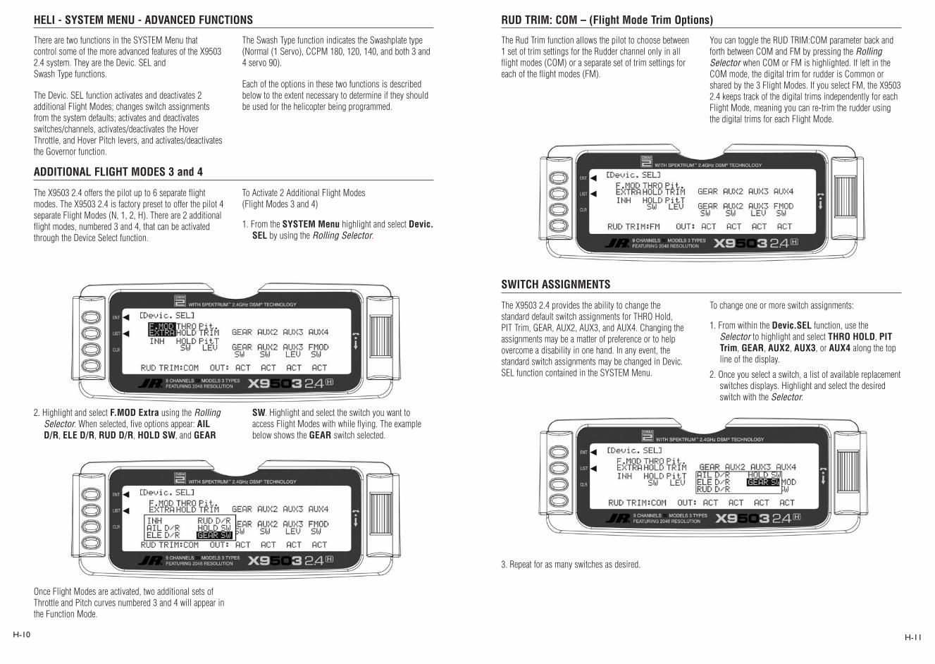
HELI - SYSTEM MENU - ADVANCED FUNCTIONS
ADDITIONAL FLIGHT MODES 3 and 4
RUD TRIM: COM – (Flight Mode Trim Options)
SWITCH ASSIGNMENTS
H-10 H-11
There are two functions in the SYSTEM Menu that control some of the more advanced features of the X9503 2.4 system. They are the Devic. SEL and Swash Type functions.
The Devic. SEL function activates and deactivates 2 additional Flight Modes; changes switch assignments from the system defaults; activates and deactivates switches/channels, activates/deactivates the Hover Throttle, and Hover Pitch levers, and activates/deactivates the Governor function.
The Swash Type function indicates the Swashplate type (Normal (1 Servo), CCPM 180, 120, 140, and both 3 and 4 servo 90).
Each of the options in these two functions is described below to the extent necessary to determine if they should be used for the helicopter being programmed.
The X9503 2.4 offers the pilot up to 6 separate flight modes. The X9503 2.4 is factory preset to offer the pilot 4 separate Flight Modes (N, 1, 2, H). There are 2 additional flight modes, numbered 3 and 4, that can be activated through the Device Select function.
To Activate 2 Additional Flight Modes (Flight Modes 3 and 4)
1. From the SYSTEM Menu highlight and select Devic. SEL by using the Rolling Selector.
2. Highlight and select F.MOD Extra using the Rolling Selector. When selected, five options appear: AIL D/R, ELE D/R, RUD D/R, HOLD SW, and GEAR
SW. Highlight and select the switch you want to access Flight Modes with while flying. The example below shows the GEAR switch selected.
Once Flight Modes are activated, two additional sets of Throttle and Pitch curves numbered 3 and 4 will appear in the Function Mode.
The Rud Trim function allows the pilot to choose between 1 set of trim settings for the Rudder channel only in all flight modes (COM) or a separate set of trim settings for each of the flight modes (FM).
You can toggle the RUD TRIM:COM parameter back and forth between COM and FM by pressing the Rolling Selector when COM or FM is highlighted. If left in the COM mode, the digital trim for rudder is Common or shared by the 3 Flight Modes. If you select FM, the X9503 2.4 keeps track of the digital trims independently for each Flight Mode, meaning you can re-trim the rudder using the digital trims for each Flight Mode.
To change one or more switch assignments:
1. From within the Devic.SEL function, use the Selector to highlight and select THRO HOLD, PIT Trim, GEAR, AUX2, AUX3, or AUX4 along the top line of the display.
2. Once you select a switch, a list of available replacement switches displays. Highlight and select the desired switch with the Selector.
The X9503 2.4 provides the ability to change the standard default switch assignments for THRO Hold, PIT Trim, GEAR, AUX2, AUX3, and AUX4. Changing the assignments may be a matter of preference or to help overcome a disability in one hand. In any event, the standard switch assignments may be changed in Devic.SEL function contained in the SYSTEM Menu.
3. Repeat for as many switches as desired.
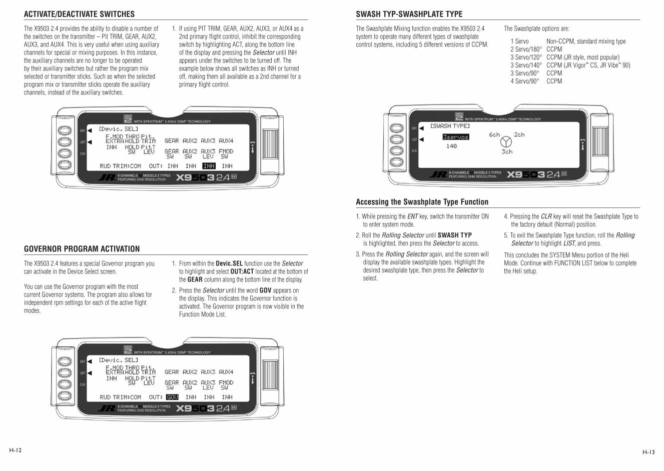
ACTIVATE/DEACTIVATE SWITCHES
GOVERNOR PROGRAM ACTIVATION
SWASH TYP-SWASHPLATE TYPE
Accessing the Swashplate Type Function
H-12 H-13
The X9503 2.4 provides the ability to disable a number of the switches on the transmitter – Pit TRIM, GEAR, AUX2, AUX3, and AUX4. This is very useful when using auxiliary channels for special or mixing purposes. In this instance, the auxiliary channels are no longer to be operated by their auxiliary switches but rather the program mix selected or transmitter sticks. Such as when the selected program mix or transmitter sticks operate the auxiliary channels, instead of the auxiliary switches.
1. If using PIT TRIM, GEAR, AUX2, AUX3, or AUX4 as a 2nd primary flight control, inhibit the corresponding switch by highlighting ACT, along the bottom line of the display and pressing the Selector until INH appears under the switches to be turned off. The example below shows all switches as INH or turned off, making them all available as a 2nd channel for a primary flight control.
The X9503 2.4 features a special Governor program you can activate in the Device Select screen.
You can use the Governor program with the most current Governor systems. The program also allows for independent rpm settings for each of the active flight modes.
1. From within the Devic.SEL function use the Selector to highlight and select OUT:ACT located at the bottom of the GEAR column along the bottom line of the display.
2. Press the Selector until the word GOV appears on the display. This indicates the Governor function is activated. The Governor program is now visible in the Function Mode List.
1. While pressing the ENT key, switch the transmitter ON to enter system mode.
2. Roll the Rolling Selector until SWASH TYP is highlighted, then press the Selector to access.
3. Press the Rolling Selector again, and the screen will display the available swashplate types. Highlight the desired swashplate type, then press the Selector to select.
4. Pressing the CLR key will reset the Swashplate Type to the factory default (Normal) position.
5. To exit the Swashplate Type function, roll the Rolling Selector to highlight LIST, and press.
This concludes the SYSTEM Menu portion of the Heli Mode. Continue with FUNCTION LIST below to complete the Heli setup.
The Swashplate Mixing function enables the X9503 2.4 system to operate many different types of swashplate control systems, including 5 different versions of CCPM.
The Swashplate options are:
1 Servo Non-CCPM, standard mixing type2 Servo/180° CCPM3 Servo/120° CCPM (JR style, most popular)3 Servo/140° CCPM (JR Vigor™ CS, JR Vibe™ 90)3 Servo/90° CCPM4 Servo/90° CCPM

HELI – FUNCTION LIST
D/R & EXP – DUAL RATE AND EXPONENTIAL
FUNCTION MODE
REV.SW - SERVO REVERSING
Auto Dual Rate
H-14 H-15
Once you’ve setup the SYSTEM settings, use the FUNCTION LIST to complete your set up and adjust how the helicopter flies and is controlled. The functions are presented below in the order that they appear in the Function List.
The descriptions are general in nature and are intended to provide enough information to decide whether or not to use a function, and what types of selections and settings to make.
Press the LIST button after the transmitter is powered up to obtain the FUNCTION LIST.
Dual Rates and Exponential curves allow you to set up your helicopter with a particular “feel” in maneuvers. Just changing D/R and EXPO values can change the helicopter’s personality, causing it to take on traits that make certain maneuvers easier for you. At times you might want the helicopter to feel very crisp, such as when performing aerobatics, and then feel softer for other maneuvers such as Hovering. And other times you want the helicopter to be very crisp but without the tendency to be over-controlled, like in performing 3D maneuvers. Dual Rates and Exponential curves can be combined to
produce these traits. When programming a Dual Rate and Exponential curve, think about what kind of response is desired from the helicopter.
1. Highlight and select D/R & EXP in the FUNC.LIST to obtain the D/R & EXP display. There will be 3 sets of values displayed for each channel – Aileron, Elevator and Rudder.
2. Use the Selector to change between Aileron, Elevator and Rudder. Then use it to set dual rate and exponential values. If you’ve never used exponential before, try a low positive value like +20. After a while, increase it gradually until the desired feel is obtained. Use only positive (+) percentages unless there is a distinct need to increase control sensitivity.
After plugging all servos into their proper channels in the receiver, you should first check each servo’s direction of travel. Move all sticks and switches/levers while observing each servo to determine if the servos are moving in the correct directions. Make note of those servos not traveling in the correct direction and use the REV.SW function to reverse the direction of travel for those servos.
1. Highlight and select REV.SW in the FUNC.LIST to obtain the servo reversing display.
2. Using the Selector, highlight and select those channels you need to reverse. Pressing the Selector toggles the channel between Normal and Reverse.
Note: If any of the versions of CCPM have been selected, the 3 CCPM channels will be re-named to CH2, CH3, and CH6, etc. on the display.
The Automatic Dual Rate function allows you to change the dual rate and expo values of the elevator, aileron, and rudder by changing the flight mode or throttle hold switch positions.
This feature simplifies the operation of multiple switches during flight.
To access the Auto D/R feature, roll the selector to the right until the D/R Expo graph is replaced by the Auto D/R Flight Mode list.
Highlight the Flight Mode to be set for Auto D/R, then press the selector to pick the desired D/R setting for this flight mode. Repeat as necessary to assign D/R positions for each flight mode.
Extended Screen

Sub-Trim TRVL ADJ. – TRAVEL ADJUST
H-16 H-17
You should use Sub-Trims for minor adjustments to servo linkages, not for major trim adjustments. Using excessive sub trim percentages can cause a loss in servo travel in one direction where the servo reaches its travel limit and stops moving before the control stick is fully deflected.
Use Sub-Trims to fine-tune the alignment of servo arms. Install servo arms on the servos so that the arms are at 90˚ or perpendicular to the servo case/linkage. As JR servos feature an odd number of splines on the output shaft, you can rotate and reinstall the arms to try and obtain a better position for the servo arm that will require a lesser amount of sub-trim. Now use the Sub-Trim function to fine-tune the servo arms that are not quite at 90˚ to the servo.
1. Highlight and select Sub-Trim in the FUNC.LIST to obtain the Sub-Trim Display.
Note: If a form of CCPM has been selected, channel naming will vary.
2. Highlight and select the channels where the servo arms are not quite at the desired position. Once a channel is selected, rotate the Selector until the servo arm is at 90˚ to the servo case.
Use Travel Adjust to alter how far a servo travels in each direction. After installing the linkages and attaching them to the servos, adjust the amount of servo travel in each direction.
1. Highlight and select TRVL ADJ. in the FUNC.LIST to obtain the Travel Adjust display.
2. Using the Selector, highlight and select each channel. Adjust the travel in each direction by rotating the Selector. You can change the direction of travel by moving the stick/switch lever back and forth.
Note: If a form of CCPM has been selected, channel naming will vary.
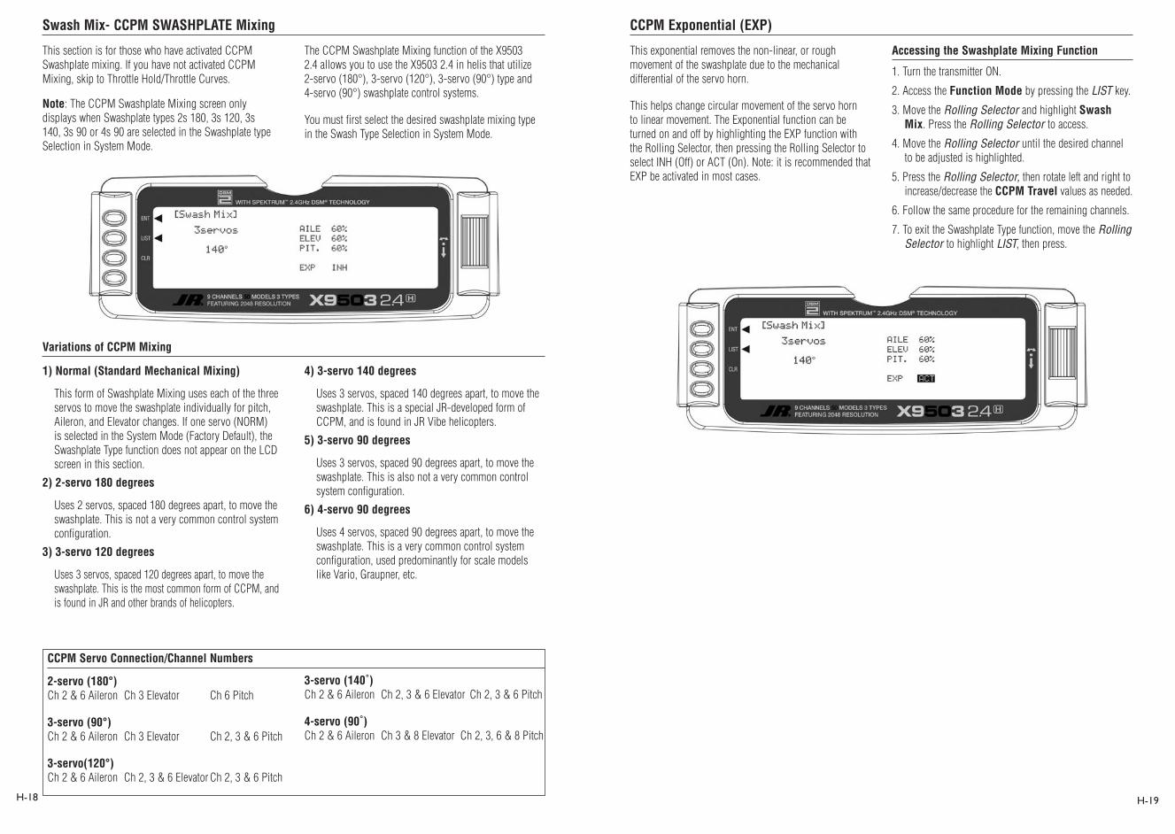
Swash Mix- CCPM SWASHPLATE Mixing CCPM Exponential (EXP)
H-18 H-19
1) Normal (Standard Mechanical Mixing)
This form of Swashplate Mixing uses each of the three servos to move the swashplate individually for pitch, Aileron, and Elevator changes. If one servo (NORM) is selected in the System Mode (Factory Default), the Swashplate Type function does not appear on the LCD screen in this section.
2) 2-servo 180 degrees
Uses 2 servos, spaced 180 degrees apart, to move the swashplate. This is not a very common control system configuration.
3) 3-servo 120 degrees
Uses 3 servos, spaced 120 degrees apart, to move the swashplate. This is the most common form of CCPM, and is found in JR and other brands of helicopters.
4) 3-servo 140 degrees
Uses 3 servos, spaced 140 degrees apart, to move the swashplate. This is a special JR-developed form of CCPM, and is found in JR Vibe helicopters.
5) 3-servo 90 degrees
Uses 3 servos, spaced 90 degrees apart, to move the swashplate. This is also not a very common control system configuration.
6) 4-servo 90 degrees
Uses 4 servos, spaced 90 degrees apart, to move the swashplate. This is a very common control system configuration, used predominantly for scale models like Vario, Graupner, etc.
This section is for those who have activated CCPM Swashplate mixing. If you have not activated CCPM Mixing, skip to Throttle Hold/Throttle Curves.
Note: The CCPM Swashplate Mixing screen only displays when Swashplate types 2s 180, 3s 120, 3s 140, 3s 90 or 4s 90 are selected in the Swashplate type Selection in System Mode.
The CCPM Swashplate Mixing function of the X9503 2.4 allows you to use the X9503 2.4 in helis that utilize 2-servo (180°), 3-servo (120°), 3-servo (90°) type and 4-servo (90°) swashplate control systems.
You must first select the desired swashplate mixing type in the Swash Type Selection in System Mode.
Variations of CCPM Mixing
This exponential removes the non-linear, or rough movement of the swashplate due to the mechanical differential of the servo horn.
This helps change circular movement of the servo horn to linear movement. The Exponential function can be turned on and off by highlighting the EXP function with the Rolling Selector, then pressing the Rolling Selector to select INH (Off) or ACT (On). Note: it is recommended that EXP be activated in most cases.
Accessing the Swashplate Mixing Function
1. Turn the transmitter ON.
2. Access the Function Mode by pressing the LIST key.
3. Move the Rolling Selector and highlight Swash Mix. Press the Rolling Selector to access.
4. Move the Rolling Selector until the desired channel to be adjusted is highlighted.
5. Press the Rolling Selector, then rotate left and right to increase/decrease the CCPM Travel values as needed.
6. Follow the same procedure for the remaining channels.
7. To exit the Swashplate Type function, move the Rolling Selector to highlight LIST, then press.
2-servo (180°) Ch 2 & 6 Aileron Ch 3 Elevator Ch 6 Pitch
3-servo (90°) Ch 2 & 6 Aileron Ch 3 Elevator Ch 2, 3 & 6 Pitch
3-servo(120°) Ch 2 & 6 Aileron Ch 2, 3 & 6 Elevator Ch 2, 3 & 6 Pitch
CCPM Servo Connection/Channel Numbers
3-servo (140˚) Ch 2 & 6 Aileron Ch 2, 3 & 6 Elevator Ch 2, 3 & 6 Pitch
4-servo (90˚) Ch 2 & 6 Aileron Ch 3 & 8 Elevator Ch 2, 3, 6 & 8 Pitch

THRO HOLD- THROTTLE HOLD Stick Auto/Auto Cut Setting
Hold Delay
H-20 H-21
The Throttle Hold function holds the throttle servo in a specific position during an autorotation. This is very useful for practicing autorotation landings. The Throttle Hold switch is located on the top right-rear corner of the transmitter (unless a different switch has been selected in the Device Sel section in the System Mode). In the forward position, Throttle Hold is on; in the rear position, Throttle Hold is off.
The proper Throttle Hold value should deliver the proper engine idle rpm for your helicopter. The adjustable range is (-20% – +50%). Once you establish the proper idle trim value for your engine, you can use this value for Throttle Hold as well. To shut the engine off for autorotation, a negative or zero value should be input.
Accessing the Throttle Hold Function
1. Place the transmitter switch in the ON position.
2. Press the List key, then move the Selector until THRO HOLD is displayed. Press the Selector to access.
3. Pressing the Selector activates (ACT) or inhibits (INH) the Throttle Hold function.
4. Once the Throttle Hold function is activated, the screen displays the current Throttle Hold value.
5. Move the Selector to highlight HOLD Pos, then press. Roll the Selector to increase or decrease the Throttle Hold value.
6. To exit the Throttle Hold function, move the Selector to highlight LIST, then press.
Note: When the Throttle Hold is activated and the switch is on, the ‘’HLD“ indication on the LCD displays just under the battery voltage bar.
The Stick Auto Setting acts as an automatic Throttle cutoff point.
This feature allows you to select the throttle stick position in which the throttle hold function can be activated in the Throttle Hold mode. Although the throttle hold switch is active, when using this feature the throttle continues to function until the throttle stick is moved below the cutoff position you select.
To activate the Stick Auto function, highlight the Stick Auto function with the selector, and press to access. Next, roll the selector to increase/decrease the position of the cutoff point.
The Hold Delay function allows the throttle servos’ movement to be slowed when switching from Throttle Hold back to a previous Flight Mode. This feature is helpful when practicing Autos. If the autorotation attempt is not going well, when the Throttle hold switch is released, the throttle increases more slowly, eliminating any sudden bursts of throttle which could damage the mechanics of the model.
The adjustable range is from 1/10 of a second, up to a full 2 seconds of delay.
To activate the Hold Delay, highlight the Hold Delay function with the selector, and press to access. Next, roll the selector to the desired delay position, and press the selector to store. A good starting value is .75 (3/4) of a second.

THRO CURV – THROTTLE CURVES Accessing the Throttle Curve Function
H-22 H-23
The X9503 2.4 offers up to five (5) separate throttle curves with up to seven adjustable points per curve. This function allows you to customize the throttle curve and pitch curve together to maximize engine performance at a particular pitch setting. Once the throttle curves are established, you can activate each in flight using the 3-position flight mode switch. If you’ve activated the additional 2 flight modes (numbers 3 and 4) in the Device Select portion of the system mode, an additional switch will be used to activate these modes.
The flight mode switch offers three selectable ranges:
N=Normal, 1=Stunt 1, and 2=Stunt 2. Optional: 3= Stunt 3, and 4= Stunt 4
Use the N (Normal) position as the hover throttle curve.
Use positions 1 and 2 (Stunt 1 and Stunt 2) for aerobatic maneuvers and forward flight. Modes 3 and 4 are optional flight modes. Use these with aerobatic maneuvers and forward flight.
Note: The throttle trim and hovering throttle levers are only operable when the flight mode switch is in the normal position. Thus, in the 1 or 2 positions, these two functions have no effect. Also, adjusting the hovering throttle lever and throttle trim has no effect on the input values of the throttle curve. Each of the five points of the throttle curve are independently adjustable from 0–100%. These five points correspond to the position of the throttle stick.
The transmitter is preset at the factory to the throttle curve as indicated by the solid line in figure 1 above. You can activate individual middle points and increase or decrease their values as desired.
The throttle trim lever position affects the low-point position as shown when in the Normal mode Throttle Curve.
for points 1, 2, 4 and 5. These values are 16.5%, 33%, 66.5% and 83.5% respectively if no value changes are made to any other points. If you change any of the other points while these were inhibited, the inhibited points change to plot a smooth curve.
To keep this from happening, highlight each point and press the Rolling Selector twice to activate each. Repeat as necessary. You can then fully adjust the values of these points with the Rolling Selector. To inhibit the points, highlight the desired point with the Rolling Selector, press the Rolling Selector to open the point, then press the clear key (CLR) to inhibit.
1. Turn the transmitter ON.
2. Press the List key simultaneously to enter the Function Mode.
3. Roll the Rolling Selector to highlight the THRO CURV function, then press to access.
Note: The letter/numbers directly to the right of THRO CURV at the top left of the LCD display the current Flight mode switch position.
Use NORM for hover curves and 1, 2, 3, and 4 (3 and 4 optional) for stunt curves. This examples shows the hovering curve.
4. Highlight the desired throttle point to be adjusted. Press the Selector to open the point value, then roll the Selector to increase and decrease the point value.
5. To set curves for flight mode switch position 1, highlight NORM with the Selector, press, then select ST-1 from the drop down box and repeat steps 4 and 5.
6. To set curves for flight mode switch positions 2 through 5, repeat step 5 above.
7. To exit the Throttle Curve function, highlight the LIST with the Selector, and press.
Note: In each curve, the factory setting indicates INH
Note: If using a governor, generally the throttle curves in stunt 1 and stunt 2 are set to flat lines at 100% throttle, allowing the governor to control the throttle servo.Figure 1: Throttle Curve Normal
Figure 2: Throttle Curve, Stunt 1
Throttle Curve, Stunt 1

Throttle Trim Lever Function
Hovering Throttle Lever
Throttle Curve Exponential
PIT. CURV/PITCH CURVES Function
Accessing the Pitch Curve Function
H-24 H-25
The throttle trim lever is only active when the flight mode switch is in the normal position. Use the throttle trim to increase or decrease the engine power when the flight mode switch is in the Normal mode. The throttle trim lever has no effect on flight modes 1, 2, 3, 4, or in throttle hold.
Note: Making changes to the throttle trim lever does not change the input values for any of the points on the throttle curve; it merely makes adjustments to the engine idle speed position.
The Hovering Throttle lever increases or decreases the engine output power for the middle three points set for the throttle curve. As shown in the figure below, using the hovering throttle lever shifts the curve upward or downward parallel with the original curve. Therefore, operation of the hovering throttle knob does not cause any change to the original settings of the throttle curve.
The throttle trim range affects the throttle curve as shown. The adjustable range of output using the hovering throttle lever is approximately +/-15 points as shown in the diagram below.
Note: The Hovering Throttle has no effect on flight mode switch positions 1 and 2.
With the X9503 2.4 system, individual throttle curves are selectable to be either straight (linear) or curved (exponential) setting. With the exponential function on, you will notice that any sharp angles of the throttle curve will become more “rounded” or “smooth”, creating more equal throttle servo movement during the entire curve range.
Accessing the Throttle Curve Exponential Function
1. From the Throttle Curve function, press the Channel key until “EXP” appears at the center of the LCD screen.
2. Highlight the EXP OFF with the Selector. Press the Selector to change the display from OFF to ON.
3. To exit the Throttle Curve function, move the Selector to highlight LIST and press.
Adjustment of the pitch curve is very similar to the throttle
curve adjustment described in the preceding section. A thorough understanding of the Throttle Curve Section will make pitch curve adjustment easier to understand. There are up to six independent types of pitch curves available: Normal, Stunt-1, Stunt-2, Stunt-3, and Stunt-4 (Stunt 3 and 4 optional) and Hold. Each pitch curve contains up to seven adjustable points: L, 1, 2, 3, 4, 5, and H.
Note: You can only set the pitch curve for the Throttle Hold function and Stunt Modes 3 and 4, if you previously activated them in the System mode.
INH for points 1, 2, 4 and 5. These values are 16.5%, 33%, 66.5% and 83.5% respectively if no value changes are made to any other points. If you change any of the other points while these points are inhibited, the inhibited points change to plot a smooth curve.
1. Turn the transmitter ON.
2. Press the LIST key to enter the Function mode.
3. Use the Selector to highlight the PIT. CURV function, and press the to access.
Note: The Letter, numbers directly to the right of PIT. CURV at the top right portion of the LCD is the current flight mode switch position. (N, 1, 2, 3, 4 or H).
Use NORMAL for hover curves and 1 through 4 (3 and 4 optional) for stunt curves. This example shows the hovering curve.
4. Highlight the desired Pitch point to be adjusted. Press the Selector to open the point value, then roll the Selector to increase and decrease the point value.
5. To set curves for flight mode switch position 1, highlight NORM with the Selector, press, then select ST-1 from the drop down box and repeat steps 4 and 5.
6. To set curves for flight mode switch positions 2 through 5, repeat step 6 above.
7. To exit the Pitch Curve function, highlight the LIST with the Selector, and press.
Note: In each curve, the factory setting indicates
To keep this from happening, highlight each point and press the Selector twice to activate each of the points. Repeat as necessary. You can fully adjust the values for these points with the Selector. To inhibit the points, highlight the desired point with the Selector, press the Selector to open the point, then press the clear key (CLR) to inhibit.

Hovering Pitch Lever REVO.MIX/Revo Mix Function: Non Heading Lock Gyros Only
H-26 H-27
The Hovering Pitch lever operates in the same manner as the Hovering Throttle knob. It is only operable while the flight mode switch is in the ‘’N’’ (normal) position, and its function is to shift the middle portion of the curve upward or downward.
Example of Throttle Curve and Pitch Curve Settings
An example of throttle curve and pitch curve settings for aerobatic specifications are shown below in the graphs. Details of the curves differ depending on the helicopter specifications. In these examples, the throttle open-close stroke and autorotation pitch stroke are set 0 to 100 to ease your understanding of other curves.
Note: Dotted line indicates Throttle and Pitch curve range/movements using the Hover Throttle and Hover Pitch levers.
The Revolution Mixing function is for conventional “Rate” gyros only, and mixes tail rotor with the Throttle and Pitch Curve functions to counteract torque from the main rotor blades. When set up correctly, the helicopter should climb and descend without a tendency to yaw in either direction. Because torque reaction varies with different power settings, it is necessary to vary the tail rotor pitch at the same time. The X9503 2.4 offers two separate revolution mixing programs, with independent up and down mixing for each—one for Flight mode position N and the other for Stunt 1 and Stunt 2 positions. The U (Up) mixing adjusts the tail rotor compensation for the mid to high
throttle setting and the D, or down, mixing adjusts the tail rotor compensation for the mid to low throttle setting. Thus, if you move the throttle from the low to high position, the tail rotor servo would move from D through Hover (mid) and to the U setting.
Note: A letter appears directly to the right of the REVO.MIX on the top of the LCD to indicate the current throttle stick/mix position (U for Up, D for Down).
Accessing the Revolution Mixing Function
1. Turn the transmitter ON.
2. Press the LIST key to enter Function Mode.
3. Use the Selector to highlight the REVO.MIX function, then press to access.
4. Highlight the Revo Mix value to be adjusted, then press to open the value. Rotate the Selector to increase or decrease the value as needed.
5. Press the CLR key to reset the values to 0% if needed.
6. To exit the Revolution Mixing function, move the Selector to highlight LIST, and press.
Setting up Revolution Mixing
Set up the helicopter so that it will hover with the tail rotor trim centered. Establish the helicopter into a stable hover, then steadily increase the throttle to initiate a steady climb. The body of the helicopter will moves in the opposite direction to the main rotor rotation. Increase the U, or Up, setting until the helicopter climbs with no tendency to turn. At a safe altitude, close the throttle; the helicopter will descend and the body turn in the same direction as the main rotor rotation. Increase the D, or down, mix until the helicopter descends with no tendency to turn. Throttle stick movements should be slow, and the initial acceleration and deceleration swings should be ignored.
When throttle is in the hold position (autorotation), revolution and acceleration mixings are off. The Acceleration Mixing function compensates for the main rotor acceleration (and deceleration) torque. The magnitude and duration of the signal to the tail rotor depends on the rate of the throttle changes. Thus, quick, jerky throttle inputs yield more noticeable tail compensation.
1 2 3 4 5L H
1 2 3 4 5L H 1 2 3 4 5L H
1 2 3 4 5L H
1 2 3 4 5L H
0%
50%
100%Pitch
0%
50%
100%Pitch
0%
50%
100%Pitch
0%
50%
100%Throttle
0%
50%
100%Throttle
NormalHover
Stunt 1Aerobatics
ThrottleHold
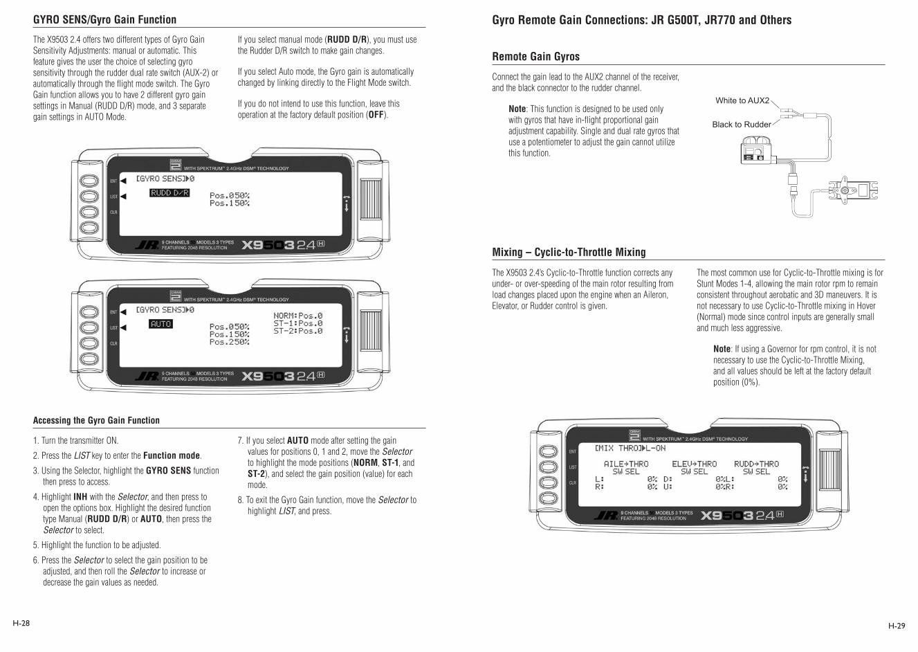
GYRO SENS/Gyro Gain Function
Accessing the Gyro Gain Function
Remote Gain Gyros
Gyro Remote Gain Connections: JR G500T, JR770 and Others
H-28 H-29
The X9503 2.4 offers two different types of Gyro Gain Sensitivity Adjustments: manual or automatic. This feature gives the user the choice of selecting gyro sensitivity through the rudder dual rate switch (AUX-2) or automatically through the flight mode switch. The Gyro Gain function allows you to have 2 different gyro gain settings in Manual (RUDD D/R) mode, and 3 separate gain settings in AUTO Mode.
If you select manual mode (RUDD D/R), you must use the Rudder D/R switch to make gain changes.
If you select Auto mode, the Gyro gain is automatically changed by linking directly to the Flight Mode switch.
If you do not intend to use this function, leave this operation at the factory default position (OFF).
1. Turn the transmitter ON.
2. Press the LIST key to enter the Function mode.
3. Using the Selector, highlight the GYRO SENS function then press to access.
4. Highlight INH with the Selector, and then press to open the options box. Highlight the desired function type Manual (RUDD D/R) or AUTO, then press the Selector to select.
5. Highlight the function to be adjusted.
6. Press the Selector to select the gain position to be adjusted, and then roll the Selector to increase or decrease the gain values as needed.
7. If you select AUTO mode after setting the gain values for positions 0, 1 and 2, move the Selector to highlight the mode positions (NORM, ST-1, and ST-2), and select the gain position (value) for each mode.
8. To exit the Gyro Gain function, move the Selector to highlight LIST, and press.
Connect the gain lead to the AUX2 channel of the receiver, and the black connector to the rudder channel.
Note: This function is designed to be used only with gyros that have in-flight proportional gain adjustment capability. Single and dual rate gyros that use a potentiometer to adjust the gain cannot utilize this function.
The X9503 2.4’s Cyclic-to-Throttle function corrects any under- or over-speeding of the main rotor resulting from load changes placed upon the engine when an Aileron, Elevator, or Rudder control is given.
Mixing – Cyclic-to-Throttle Mixing
The most common use for Cyclic-to-Throttle mixing is for Stunt Modes 1-4, allowing the main rotor rpm to remain consistent throughout aerobatic and 3D maneuvers. It is not necessary to use Cyclic-to-Throttle mixing in Hover (Normal) mode since control inputs are generally small and much less aggressive.
Note: If using a Governor for rpm control, it is not necessary to use the Cyclic-to-Throttle Mixing, and all values should be left at the factory default position (0%).
1 ON
2
Black to Rudder
White to AUX2
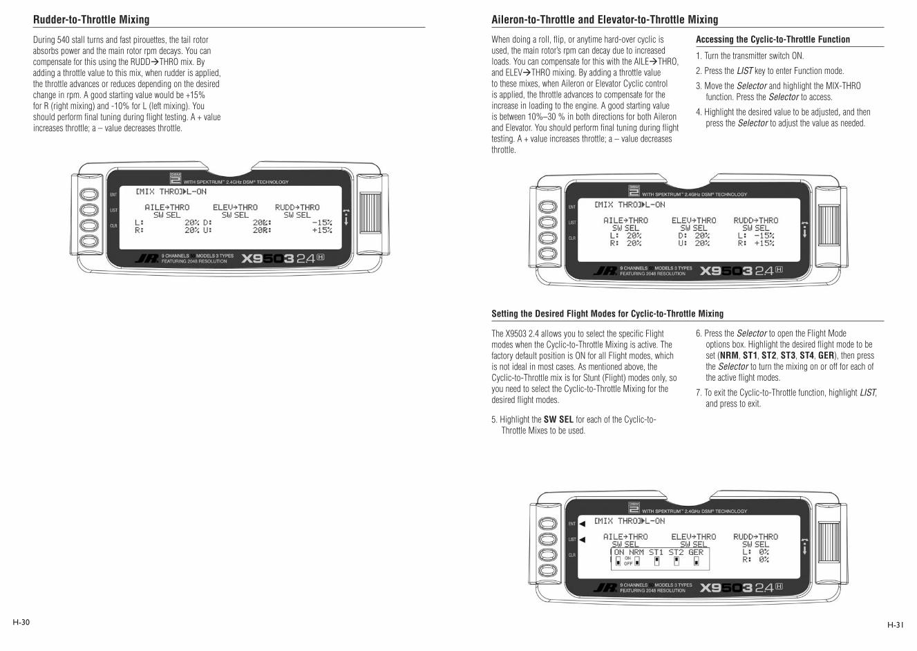
Rudder-to-Throttle Mixing Aileron-to-Throttle and Elevator-to-Throttle Mixing
Setting the Desired Flight Modes for Cyclic-to-Throttle Mixing
H-30 H-31
During 540 stall turns and fast pirouettes, the tail rotor absorbs power and the main rotor rpm decays. You can compensate for this using the RUDDTHRO mix. By adding a throttle value to this mix, when rudder is applied, the throttle advances or reduces depending on the desired change in rpm. A good starting value would be +15% for R (right mixing) and -10% for L (left mixing). You should perform final tuning during flight testing. A + value increases throttle; a – value decreases throttle.
When doing a roll, flip, or anytime hard-over cyclic is used, the main rotor’s rpm can decay due to increased loads. You can compensate for this with the AILETHRO, and ELEVTHRO mixing. By adding a throttle value to these mixes, when Aileron or Elevator Cyclic control is applied, the throttle advances to compensate for the increase in loading to the engine. A good starting value is between 10%–30 % in both directions for both Aileron and Elevator. You should perform final tuning during flight testing. A + value increases throttle; a – value decreases throttle.
Accessing the Cyclic-to-Throttle Function
1. Turn the transmitter switch ON.
2. Press the LIST key to enter Function mode.
3. Move the Selector and highlight the MIX-THRO function. Press the Selector to access.
4. Highlight the desired value to be adjusted, and then press the Selector to adjust the value as needed.
The X9503 2.4 allows you to select the specific Flight modes when the Cyclic-to-Throttle Mixing is active. The factory default position is ON for all Flight modes, which is not ideal in most cases. As mentioned above, the Cyclic-to-Throttle mix is for Stunt (Flight) modes only, so you need to select the Cyclic-to-Throttle Mixing for the desired flight modes.
5. Highlight the SW SEL for each of the Cyclic-to-Throttle Mixes to be used.
6. Press the Selector to open the Flight Mode options box. Highlight the desired flight mode to be set (NRM, ST1, ST2, ST3, ST4, GER), then press the Selector to turn the mixing on or off for each of the active flight modes.
7. To exit the Cyclic-to-Throttle function, highlight LIST, and press to exit.
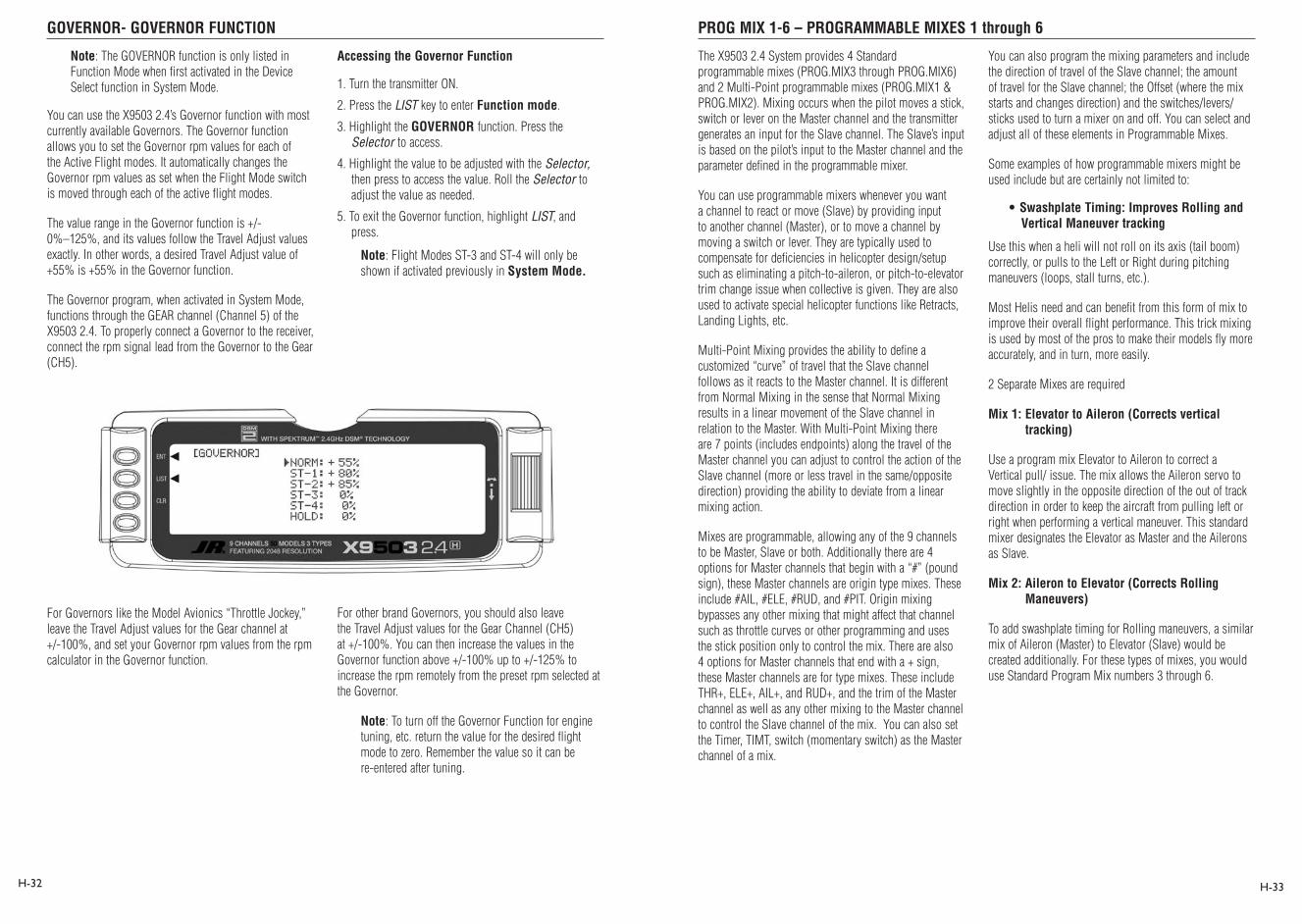
GOVERNOR- GOVERNOR FUNCTION PROG MIX 1-6 – PROGRAMMABLE MIXES 1 through 6
H-32 H-33
Note: The GOVERNOR function is only listed in Function Mode when first activated in the Device Select function in System Mode.
You can use the X9503 2.4’s Governor function with most currently available Governors. The Governor function allows you to set the Governor rpm values for each of the Active Flight modes. It automatically changes the Governor rpm values as set when the Flight Mode switch is moved through each of the active flight modes.
The value range in the Governor function is +/- 0%–125%, and its values follow the Travel Adjust values exactly. In other words, a desired Travel Adjust value of +55% is +55% in the Governor function.
The Governor program, when activated in System Mode, functions through the GEAR channel (Channel 5) of the X9503 2.4. To properly connect a Governor to the receiver, connect the rpm signal lead from the Governor to the Gear (CH5).
Accessing the Governor Function
1. Turn the transmitter ON.
2. Press the LIST key to enter Function mode.
3. Highlight the GOVERNOR function. Press the Selector to access.
4. Highlight the value to be adjusted with the Selector, then press to access the value. Roll the Selector to adjust the value as needed.
5. To exit the Governor function, highlight LIST, and press.
Note: Flight Modes ST-3 and ST-4 will only be shown if activated previously in System Mode.
For Governors like the Model Avionics “Throttle Jockey,” leave the Travel Adjust values for the Gear channel at +/-100%, and set your Governor rpm values from the rpm calculator in the Governor function.
For other brand Governors, you should also leave the Travel Adjust values for the Gear Channel (CH5) at +/-100%. You can then increase the values in the Governor function above +/-100% up to +/-125% to increase the rpm remotely from the preset rpm selected at the Governor.
Note: To turn off the Governor Function for engine tuning, etc. return the value for the desired flight mode to zero. Remember the value so it can be re-entered after tuning.
The X9503 2.4 System provides 4 Standard programmable mixes (PROG.MIX3 through PROG.MIX6) and 2 Multi-Point programmable mixes (PROG.MIX1 & PROG.MIX2). Mixing occurs when the pilot moves a stick, switch or lever on the Master channel and the transmitter generates an input for the Slave channel. The Slave’s input is based on the pilot’s input to the Master channel and the parameter defined in the programmable mixer.
You can use programmable mixers whenever you want a channel to react or move (Slave) by providing input to another channel (Master), or to move a channel by moving a switch or lever. They are typically used to compensate for deficiencies in helicopter design/setup such as eliminating a pitch-to-aileron, or pitch-to-elevator trim change issue when collective is given. They are also used to activate special helicopter functions like Retracts, Landing Lights, etc.
Multi-Point Mixing provides the ability to define a customized “curve” of travel that the Slave channel follows as it reacts to the Master channel. It is different from Normal Mixing in the sense that Normal Mixing results in a linear movement of the Slave channel in relation to the Master. With Multi-Point Mixing there are 7 points (includes endpoints) along the travel of the Master channel you can adjust to control the action of the Slave channel (more or less travel in the same/opposite direction) providing the ability to deviate from a linear mixing action.
Mixes are programmable, allowing any of the 9 channels to be Master, Slave or both. Additionally there are 4 options for Master channels that begin with a “#” (pound sign), these Master channels are origin type mixes. These include #AIL, #ELE, #RUD, and #PIT. Origin mixing bypasses any other mixing that might affect that channel such as throttle curves or other programming and uses the stick position only to control the mix. There are also 4 options for Master channels that end with a + sign, these Master channels are for type mixes. These include THR+, ELE+, AIL+, and RUD+, and the trim of the Master channel as well as any other mixing to the Master channel to control the Slave channel of the mix. You can also set the Timer, TIMT, switch (momentary switch) as the Master channel of a mix.
You can also program the mixing parameters and include the direction of travel of the Slave channel; the amount of travel for the Slave channel; the Offset (where the mix starts and changes direction) and the switches/levers/sticks used to turn a mixer on and off. You can select and adjust all of these elements in Programmable Mixes.
Some examples of how programmable mixers might be used include but are certainly not limited to:
• Swashplate Timing: Improves Rolling and Vertical Maneuver tracking
Use this when a heli will not roll on its axis (tail boom) correctly, or pulls to the Left or Right during pitching maneuvers (loops, stall turns, etc.).
Most Helis need and can benefit from this form of mix to improve their overall flight performance. This trick mixing is used by most of the pros to make their models fly more accurately, and in turn, more easily.
2 Separate Mixes are required
Mix 1: Elevator to Aileron (Corrects vertical tracking)
Use a program mix Elevator to Aileron to correct a Vertical pull/ issue. The mix allows the Aileron servo to move slightly in the opposite direction of the out of track direction in order to keep the aircraft from pulling left or right when performing a vertical maneuver. This standard mixer designates the Elevator as Master and the Ailerons as Slave.
Mix 2: Aileron to Elevator (Corrects Rolling Maneuvers)
To add swashplate timing for Rolling maneuvers, a similar mix of Aileron (Master) to Elevator (Slave) would be created additionally. For these types of mixes, you would use Standard Program Mix numbers 3 through 6.

PROG MIX 1-6 – PROGRAMMABLE MIXES 1 through 6 (continued) Swashplate Timing Mixes Example: Elevator-to-Aileron (Corrects Vertical Tracking)
H-34 H-35
• Eliminate Pitch to Collective Trim Changes (non CCPM only)
Use this when the Heli rolls left or right, or pitches fore or aft when a collective input is given. This is commonly caused by a mechanical geometry issue in the design of the servo linkages and mechanical mixers/levers. By using a program mix for Pitch-to-Aileron to correct an Aileron trim change issue, the mix allows the Aileron servo to move slightly in the opposite direction of the out of trim direction in order to keep the helicopter from rolling, while Collective pitch is added or reduced. This standard mixer designates the Pitch (Collective) as the Master and the Ailerons as the Slave. For this type of Mix, you would use Standard Program Mixes 3 through 6.
• Activating Retractable Gear via the Flight Mode switch
This form of mix allows you to activate your retractable landing gear via your Flight mode switch. It could be set so that in Normal (Hover) and Throttle Hold (Hold) modes, the retracts would be down, and when you move the Flight Mode switch to positions 1 or 2, the retracts would automatically go up and stay up in these modes until you return to Normal or Throttle Hold. This type of mix reduces the workload on you, so you can focus on flying your model. This type of mix uses Multi -Point Programmable mixes 1 or 2, and designates FMOD (Flight Mode switch) as the Master and Gear or another unused auxiliary channel as the slave.
The possibilities are endless and limited only by the imagination.
The example below demonstrates a program mix for a heli that pulls or climbs to the left when pulling vertical into a maneuver such as a loop or stall turn. If you set up a mix to provide a couple of degrees of Right aileron when up Elevator is given, the aircraft then climbs vertically with no change in Aileron tracking.
This mix uses the Elevator as the Master and the Aileron as the Slave. You can turn it on and off via the Flight Mode switch, so you can activate the mix only in the flight modes where the trim change is noted, most commonly forward flight modes 1–4 only.
Select and set the mix parameters in the following order: Program Mix number (3-6), Master and Slave channels, Mix Position and Flight Mode. This is generally a good sequence to follow when setting up a Programmable Mix. In this situation, the Offset value would remain at 0% (1/2 Stick).
Highlight and select one of the Standard Programmable Mixers (PROG.MIX3PROG.MIX6) to obtain the first Programmable Mix display. Then press ACT next to CLR or highlight and select INH to obtain the main mix display. The example is using PROG.MIX3.
1. Select Master. All Programmable Mixers default to Throttle as both the Master and the Slave (THROTHRO). The first THRO is the Master and the second THRO represents the Slave. Since the Elevator is the Master in this example, highlight the first channel with the Selector and select ELEV to the left of the arrow.
2. Select Slave. Highlight and select THRO to the right of the arrow to obtain a list of channels that can be the Slave. Highlight and select AILE as the Slave.
3. Select Position and Flight Modes. Move the Selector to highlight each of the active flight modes (NRM, ST1,ST2, ST3, ST4, GER, then select the mix position (0 or 1) to be used. Since the mix value will be in position 1, the flight modes where the mix would not be required would be set to the POS 0 mix position (will be left at 0%).
The number will change from 0 to 1 as the switch is moved back and forth. When the number is 0, the mixer looks at the Pos0 values (not programmed yet) and when it is a 1 it looks at the Pos1 values (also not programmed yet). For this example, assume this mix will be used in Stunt Modes 1 and 2 only.

Swashplate Timing Mixes (continued) Swashplate Timing: Aileron-to-Elevator (Corrects Rolling Maneuvers)
H-36 H-37
4. Travel and Direction. Highlight POS 1 with the Selector and press to access the values. Move the Elevator stick to the full up position and the lower value next to Pos1 should be highlighted. Set the lower Pos1 parameter to a low negative or positive value (check aileron function for proper direction) to a starting value of between 3% and 5%. This is the amount of deflection of the Aileron (Slave channel) that occurs when the mixer is turned on and the Elevator is pulled up.
Example: If the model pulls to the left during a loop, set a value so that when up Elevator is given, the mix would provide a small amount of right Aileron to correct this problem.
If an Elevator-to-Aileron mixing value is also required for Down Elevator, move the Elevator stick to the down position. You can then highlight and adjust the Pos0 mix value as needed.
5. Offset. Leave the offset value to 0% for this mix, adding 0% will correspond to the center stick position.
6. Verify Proper Mix Operation. Move the Flight Model switch to the Stunt 1 or Stunt 2 positions, and move the elevator stick from center to full up, and from center stick to full down. If the mix is activated and functioning properly, you should see a slight aileron servo movement (easiest to see at the aileron servo arm) when the Elevator stick is moved. Please verify that the Aileron servo moves in the desired direction to correct the trim problem at this time. Next, switch the Flight Mode switch to the Normal or Throttle Hold positions (set to off in this example), and verify that the mix is being turned off for these desired flight modes.
This mix functions and is set up as described in the Elevator-to-Aileron Mix section. It allows the helicopter to roll more axial along the Tail Boom by adding a slight amount of Elevator to each direction of Aileron.
Setup Tip: Most helicopters with a Clockwise Rotation Rotor require a small amout of Up Elevator for right rolls, and a small amount of Down Elevator for left rolls.
Highlight and select one of the Standard Programmable Mixers (PROG.MIX3PROG.MIX6) to obtain the first Programmable Mix display. Then press ACT next to CLR or highlight and select INH to obtain the main mix display. The example is using PROG.MIX3.
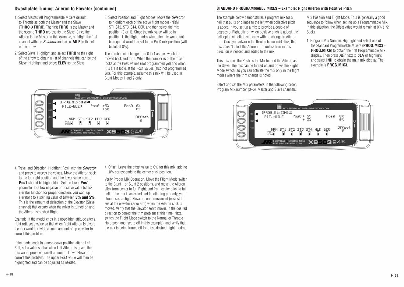
Swashplate Timing: Aileron to Elevator (continued) STANDARD PROGRAMMABLE MIXES – Example: Right Aileron with Positive Pitch
H-38 H-39
1. Select Master. All Programmable Mixers default to Throttle as both the Master and the Slave (THROTHRO). The first THRO is the Master and the second THRO represents the Slave. Since the Aileron is the Master in this example, highlight the first channel with the Selector and select AILE to the left of the arrow.
2. Select Slave. Highlight and select THRO to the right of the arrow to obtain a list of channels that can be the Slave. Highlight and select ELEV as the Slave.
3. Select Position and Flight Modes. Move the Selector to highlight each of the active flight modes (NRM, ST1,ST2, ST3, ST4, GER, and then select the mix position (0 or 1). Since the mix value will be in position 1, the flight modes where the mix would not be required would be set to the Pos0 mix position (will be left at 0%).
The number will change from 0 to 1 as the switch is moved back and forth. When the number is 0, the mixer looks at the Pos0 values (not programmed yet) and when it is a 1 it looks at the Pos1 values (also not programmed yet). For this example, assume this mix will be used in Stunt Modes 1 and 2 only.
4. Travel and Direction. Highlight Pos1 with the Selector and press to access the values. Move the Aileron stick to the full right position and the lower value next to Pos1 should be highlighted. Set the lower Pos1 parameter to a low negative or positive value (check elevator function for proper direction, you want up elevator ) to a starting value of between 3% and 5%. This is the amount of deflection of the Elevator (Slave channel) that occurs when the mixer is turned on and the Aileron is pushed Right.
Example: If the model ends in a nose-high attitude after a right roll, set a value so that when Right Aileron is given, the mix would provide a small amount of up elevator to correct this problem.
If the model ends in a nose-down position after a Left Roll, set a value so that when Left Aileron is given, the mix would provide a small amount of Down Elevator to correct this problem. The upper Pos1 value will then be highlighted and can be adjusted as needed.
4. Offset. Leave the offset value to 0% for this mix, adding 0% corresponds to the center stick position.
Verify Proper Mix Operation. Move the Flight Mode switch to the Stunt 1 or Stunt 2 positions, and move the Aileron stick from center to full Right, and from center stick to full Left. If the mix is activated and functioning properly, you should see a slight Elevator servo movement (easiest to see at the elevator servo arm) when the Aileron stick is moved. Verify that the Elevator servo moves in the desired direction to correct the trim problem at this time. Next, switch the Flight Mode switch to the Normal or Throttle Hold positions (set to off in this example), and verify that the mix is being turned off for these desired flight modes.
The example below demonstrates a program mix for a heli that pulls or climbs to the left when collective pitch is added. If you set up a mix to provide a couple of degrees of Right aileron when positive pitch is added, the helicopter will climb vertically with no change in Aileron trim. Once you advance the throttle below mid stick, the mix doesn’t affect the Aileron trim unless trim in this direction is needed and added to the mix.
This mix uses the Pitch as the Master and the Aileron as the Slave. The mix can be turned on and off via the Flight Mode switch, so you can activate the mix only in the flight modes where the trim change is noted.
Select and set the Mix parameters in the following order: Program Mix number (3–6), Master and Slave channels,
Mix Position and Flight Mode. This is generally a good sequence to follow when setting up a Programmable Mix. In this situation, the Offset value would remain at 0% (1/2 Stick).
1. Program Mix Number. Highlight and select one of the Standard Programmable Mixers (PROG.MIX3 - PROG.MIX6) to obtain the first Programmable Mix display. Then press ACT next to CLR or highlight and select INH to obtain the main mix display. The example is PROG.MIX3.

STANDARD PROGRAMMABLE MIXES – Example: Right Aileron with Positive Pitch (continued) MULTI-POINT MIXES – Example: FMOD to Gear Mixing (Retract and other Functions)
H-40 H-41
2. Select Master. All Programmable Mixers default to Throttle as both the Master and the Slave (THROTHRO). The first THRO is the Master and the 2nd THRO represents the Slave. Since the Pitch is the Master in this example, highlight the first channel with the Selector and select PIT to the left of the arrow.
3. Select Slave. Highlight and select THRO to the right of the arrow to obtain a list of channels that can be the Slave. Highlight and select AILE as the Slave.
4. Select Position and Flight Modes. Move the Selector to highlight each of the active flight modes (NRM, ST1, ST2, ST3, ST4, GER, and then select the mix position (0 or 1). Since the mix value will be in position 0, the flight modes where the mix would not be required would be set to the POS 1 mix position (will be left at 0%).
The number changes from 0 to 1 as the switch is moved back and forth. When the number is 0, the mixer looks at the Pos0 values (not programmed yet) and when it is a 1 it looks at the Pos1 values (also not programmed yet). For this example, assume this mix will be used in Stunt Modes 1 and 2 only.
5. Travel and Direction. Highlight Pos0 with the Selector and Press to access the values. Move the throttle stick to the full high position and the upper value next to Pos0 should be highlighted. Set the higher Pos0 parameter to a low negative or positive value (check aileron function for proper direction) to a starting value of between 3% and 5%. This is the amount of deflection of the Aileron (Slave channel) that occurs when the mixer is turned on and the throttle is moved from center to full throttle.
If an Aileron mixing value is also required for center stick to low Pitch, move the throttle stick to the low position. You can then highlight and adjust the Pos0 mix value as needed.
6. Offset. Leave the offset value to 0% for this mix, and 0% corresponds to the center stick position.
7. Verify Proper Mix Operation. Move the Flight Model switch to the Stunt 1 or Stunt 2 positions, and move the Throttle stick from center to full throttle, and from center stick to low throttle. If the mix is activated and functioning properly, you should see a slight aileron servo movement (easiest to see at the aileron servo arm) when the throttle stick is moved. Verify that the Aileron servo moves in the desired direction to correct the trim problem. Next, switch the Flight Mode switch to the Normal or Throttle Hold positions (set to off in this example), and verify that the mix is being turned off for these desired flight modes.
The example below demonstrates a Multi-Point Program Mix for coupling the Retractable Gear function to the Flight Mode switch so the Gear automatically moves up and down when moving through the Flight modes.
This Multi-Point mix (mixes 1 and 2) will use the FMOD (Flight Mode switch) as the Master and the Gear (or other available auxiliary channels) as the Slave. The mix will be activated with the Flight Mode switch.
Select and set the Mix parameters in the following order: Program Mix number (1 or 2), Master and Slave Channels, switch Selection, Set Points Travel/Direction, and Expo. This is generally a good sequence to follow when setting up Multi-Point Programmable Mixers.
1. Program Mix Number. Highlight and select one of the Multi-Point Programmable Mixers (PROG.MIX1 or PROG.MIX2) to obtain the first Multi-Point Programmable Mix display. Then press ACT next to CLR or highlight and select INH to obtain the main mix display. The example is using PROG.MIX1.
Flight Mode switch in Normal position
2. Select Master. All Programmable Mixers default to Throttle as both the Master and the Slave (THROTHRO). The first THRO is the Master and the second THRO represents the Slave. Highlight and select the first THRO to the left of the arrow to obtain a list of channels and select FMOD as the Master.
3. Select Slave. Highlight and select THRO to the right of the arrow to obtain a list of channels that can be the Slave. Highlight and select GEAR as the Slave. Now, if you move the Flight Mode or Throttle Hold switches, the vertical cursor on the screen moves to one of the 7 points for each of the flight modes. Point 1 will be Normal, Point 2 will be Stunt 1, Point 3 will be Stunt 2, and Point 6 will be Throttle Hold.

MULTI-POINT MIXES – FMOD to Gear (continued) MULTI-POINT MIXES – FMOD to Gear (continued)
H-42 H-43
4. Select switch. Scroll down, highlight, and press SW SELECT. The Box displays the activated Flight Modes. Move the Selector to highlight each of the Flight Modes, and press to select ON or OFF for the mix in each of the Flight Modes. For this example, the Mix will be set to the ON position for Flight Modes NRM, ST1, ST2, and HLD.
Flight Mode Switch in ST1 Position
Flight Mode Switch in ST2 Position
Flight Mode Switch in Hold Position
5. Set Points for Travel and Direction. Seven points will display. A negative value at a point typically indicates a Gear Up movement at that point and a positive value, a Gear Down movement. Reverse the direction of travel (Up Gear vs. Down Gear) by changing values from negative (-) to positive (+) (moving the point values above and below the 0% line).
Set the points initially to the following values.
Point-0 -0%Point-1 +80% (Normal Mode, Gear Down)Point-2 -80% (Stunt 1, Gear Up)Point-3 -80% (Stunt 2, Gear Up)Point-4 INH (Stunt 3 if Activated)Point-5 INH (Stunt 4 if Activated)Point-6 +80% (Throttle Hold, Gear Down)
7. EXP (Expo). With this mixing example, it is not necessary to activate the Expo option.
8. Verify Operation. Power up the receiver, making sure that the heli is elevated for the first time in case the Gear is functioning in the opposite direction desired. Move the Flight Mode and Throttle Hold switches, and note the position (Up or Down) of the retracts. If the retracts function in the opposite direction desired, then enter the mix again and change the value from a + to a -, or a – to a + as needed and retest.

Trainer – Programmable Trainer System
H-44 H-45
The X9503 2.4 contains a Trainer System that allows the instructor to transfer some or all of the primary flight control functions (Throttle, Aileron, Elevator and Rudder) to the student. It also allows for indicating if the transmitter is to be the Master or Slave. The Trainer (TRN) switch transfers control to the student when the X9503 2.4 is being used as the Master/Instructor transmitter. All Dual rates and Exponential settings in the Master transmitter are transferred to the Slave transmitter when the master transmitter channels are selected individually in the trainer menu. The Slave transmitter battery must be charged.
1. Connect the Trainer cord between the Master and Slave transmitters. Turn the power on to the Master transmitter. The Slave transmitter remains powered off and can even have the module removed.
2. Make sure the Slave transmitter is in the PPM/FM modulation mode. If the slave system is a X9503 2.4 or any other Spread Spectrum system, such as other JR 2.4GHz or Spektrum systems, this does not apply.
3. Highlight and select Trainer in the FUNCTION LIST to obtain the Trainer Display.
4. If using the X9503 2.4 as the Master transmitter, select the channel(s) the Slave transmitter will operate when in trainer mode.
X9503 2.4 USED AS MASTER (INSTRUCTOR) – (Trainer System)
When all channel selectors are in the MAST position, NORMAL appears on the display and all 4 channels are transferred to the student when the trainer switch is depressed.
When all channel selectors are in the MAST position, the slave system must be programmed for the model, meaning all programming necessary for the model must be programmed in both the master and the slave systems. Also when all the channel selectors are in the MAST position, the slave system should be left in normal default MASTER mode. To transfer only certain channels to the student, highlight and select the channels that you will transfer, moving the indicator for these channels to the SLAV position for these channels. When less than all channels are selected as SLAV, PROGRAM T appears
on the display indicating that the Trainer System has been programmed to transfer only selected channels. When the channel selectors are in the SLAV position, all programming of the master system will be used, and only the stick movements of the 4 primary channels are used from the slave system when control is given to the slave transmitter. In this case, the slave system does not need to be programmed for the model. Also the slave system should be set to Slave mode in its trainer system. The X9503 2.4 is now ready to be the Master or instructor transmitter. Depress the trainer switch to transfer control to the student. Control will remain transferred until the trainer switch is released.
X9503 2.4 USED AS SLAVE (STUDENT) – (Trainer System)
Highlight and select MASTER and the display switches to SLAVE. A message appears instructing to Connect DSC & POWER off. Make sure the transmitter power switch is in the OFF position and the trainer cord is connected between the 2 transmitters. If the master system is an XP9303, X9303 2.4, X9503 2.4, or 12X and the individual channels are not selected in the master system’s trainer function, leave the slave system’s trainer
function in the default MASTER setting. In this case, both the master and the slave systems must be fully programmed and set up to fly the model including all servo reversing, travel adjust, program mixes and all other necessary programming.
You can now use the X9503 as the Slave transmitter.

Timer – Timer System MONITOR- SERVO MONITOR
H-46 H-47
The X9503 2.4 contains a Timer System with two timers. One is an integrated timer that keeps track of total transmitter-on time for the model and displays on the Main display. You can configure this as a Countdown timer or Stopwatch. This timer also appears on the Main display when active and can be started, stopped and reset from the Main display. It is a good idea to use the Countdown timer as a reminder that it is time to land so as not to run out of fuel. If using the Countdown timer,
an Auto Start function is available that will start the timer when the throttle is raised over 20% the first time after the transmitter is turned on.1. To configure the timer as a Countdown timer, highlight
and select Timer in the FUNCTION LIST to obtain the Timer display.
Highlight and select INH under TIMER then select DOWN-T. Use the Selector to set the countdown start time. Once the timer is set, TIM appears in the lower left corner of the Main display. Press the button next to TIM on the Main display to start and stop the timer. Press the button next to CLR to reset the time to the programmed value.
2. To Reset the Integrated Timer, highlight and select the time under INTEG-T. Push [CLR]=0:00 appears on the display. Press the CLR button to the left of the display to reset the integrated timer.
The Servo Monitor function displays each channel and shows the movement of channels when sticks, levers and switches are moved. It renames channels according to special assignments to assist in identifying what is moving. For instance, when 120 CCPM Swashplate Type is selected, the Servo Monitor displays CH-2, CH-3, and
CH-6. It is a handy way to determine what channels are mixed with other channels and verify programming when the helicopter is not at hand. The Monitor function also displays the current value of all digital trims.
1. To access the Monitor function, highlight and select MONITOR in the FUNCTION LIST to obtain the Monitor display.
2. The default display (MONI) shows the settings of all digital trims. To view the Monitor display of all channels, highlight and select MONI. View the display while moving sticks, switches and levers to see the movements of various channels.
3. To view the Digital Trim values and Hover Pitch (HOV P) and Hover Throttle (HOV T) Lever values, Highlight MONI with the Selector and press. The word MONI changes to TRIM to show the trim values for these levers. To move back to the Channels display, press TRIM to return to MONI and the servo travel and output positions display once again.
Note: If you’ve selected any CCPM mixing, channel naming will vary.
3. If the Auto Start function is desired which starts the timer by the throttle stick, select INH next to STICK and select this to ACT. With this set to ACT, the Auto Start function will start the timer when the throttle stick is raised above 20%.
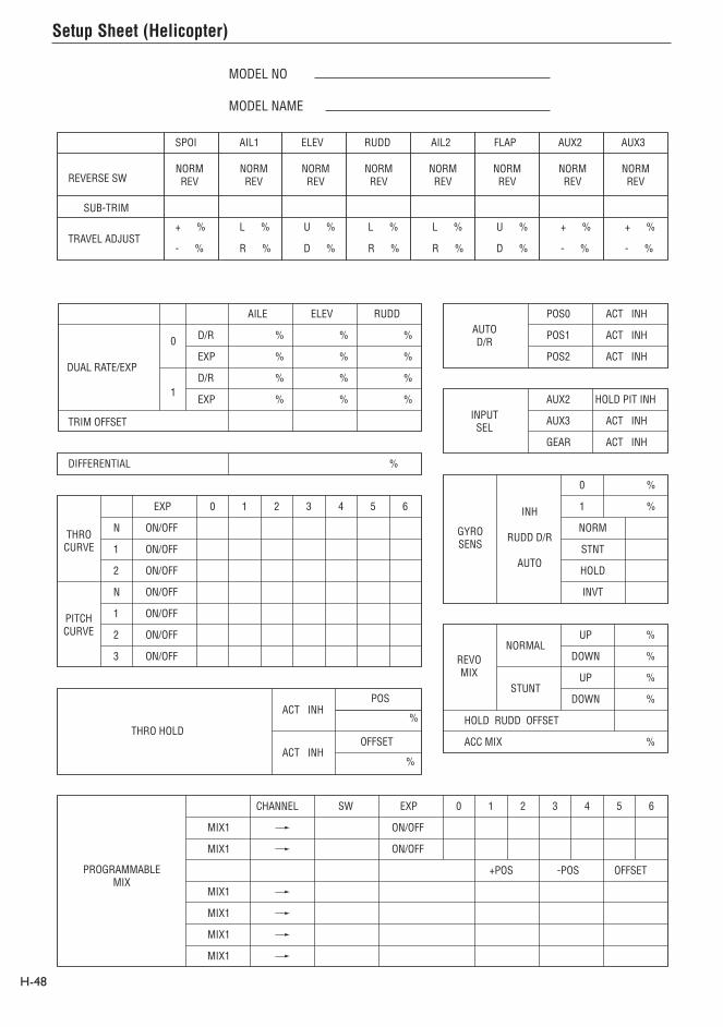
Setup Sheet (Helicopter)
MODEL NO
MODEL NAME
SPOI AIL1 ELEV RUDD AIL2 FLAP AUX2 AUX3
REVERSE SW
SUB-TRIM
TRAVEL ADJUST
AILE ELEV RUDD
DUAL RATE/EXP
0
1
D/R
EXP
D/R
EXP
%
%
%
%
%
%
%
%
%
%
%
%
TRIM OFFSET
DIFFERENTIAL %
NORMREV
NORMREV
NORMREV
NORMREV
NORMREV
NORMREV
NORMREV
NORMREV
+ %
- %
L %
R %
U %
D %
L %
R %
+ %
- %
+ %
- %
L %
R %
U %
D %
PROGRAMMABLEMIX
MIX1
MIX1
MIX1
MIX1
MIX1
MIX1
CHANNEL SW EXP 0 1 2 3 4 5 6
ON/OFF
EXP 0 1 2 3 4 5 6
ON/OFF
+POS -POS OFFSET
ON/OFF
POS0
POS1
POS2
AUTOD/R
ACT INH
ACT INH
ACT INH
AUX2
AUX3
GEAR
INPUTSEL
HOLD PIT INH
ACT INH
ACT INH
ON/OFF
ON/OFF
ON/OFF
ON/OFF
ON/OFF
ON/OFF
N
1
2
N
1
2
3
THROCURVE
PITCHCURVE
NORM
STNT
HOLD
INVT
0
1
%
%
GYROSENS
INH
RUDD D/R
AUTO
%UPNORMAL
REVOMIX
%
%
%
%
STUNT
DOWN
UP
DOWN
HOLD RUDD OFFSET
ACC MIXACT INH
ACT INHPOS
OFFSET
%
%
THRO HOLD
H-48

S-1
The GLID mode is intended for multi-function sailplanes. Up to 5 flight modes are available, each allowing virtually every parameter to be individually adjusted. Active flight mode digital trims allow in-flight adjustments of camber, elevator, rudder and aileron. Trim settings are automatically stored and recalled in each individual flight mode. Following is a list of sailplane specific programming menus and their primary functions.
Note: When Glider Model Type is used the servo port assignments on the receiver change to accommodate a full-house (6 servos) sailplane using the first 6 ports of the receiver.
GLID Model Type Servo Port Assignments1 - LAIL
2 - RAIL
3 - ELEV
4 - RUDD
5 - MOTO/* RFLP
6 - FLAP/* LFLP
7 - AUX2
8 - AUX3
9 - AUX4
* When DUAL Flap is Activated in Wing Type
SYSTEM MODE GLID FEATURES
• Trim Step–Allows the trim authority to be adjusted or even turned off.
• Device Select–Program Flight modes, switch and lever locations and functions in this menu.
• Wing Type–Allows the selection of V-tail and dual or single flap servos.
• Selectable switch positions for flight modes are available.
FUNCTION MODE GLID FEATURES
• Elevator-to-Flap–Allows two values of elevator-to-flap mixing with independent up and down adjustments. Offset allows you to program snap flaps. You can automatically select the mix in any desired flight mode or via several switch options.
• Aileron-to-Flap–Allows two values of aileron-to-flap mixing with independent right and left adjustment. You can select this mix automatically in any desired flight mode or via several switch options.
• Aileron and Flap Differential–Separate differential values (5) are available in each flight mode including reverse differential (for landing). Aileron and flap differentials are independently adjustable.
• Camber Adjust Delay–You can program a delay up to 2 seconds for each individual flight mode so the camber and elevator transition smoothly when you switch flight modes. A break-off delay allows an elevator stick position to override the delay, useful when switching from launch to cruise mode for a zoom launch.
• Camber Mix–Allows individual up and down flaperon and elevator values for each of the 5 flight modes to be adjusted via the side lever.
• Aileron-to-Rudder Mix–Features separate right and left mix values for each of the 5 available flight modes.
• The Butterfly Menu–Provides 2 settings for flaps, flaperons and elevator values using the spoiler stick. You can select each value via flight modes or several available switches.
• Flap Rate–Allows the flap camber up and down to be adjusted independently in each of the 5 flight modes via the side lever(s).
• Programmable Mix 1–Spoiler-to-elevator curve mix allows non-linear elevator compensation when using a landing flap (butterfly/ crow) . A 6-point adjustable curve allows precise elevator input throughout flap travel avoiding unwanted pitching during landings.
• 2 Timers–Count up or down, and are assignable to various switches and buttons.
• Active Digital Flight Trims–Allow presets of elevator, camber, rudder and aileron to be adjusted in flight and are automatically stored and recalled in each of the 5 flight modes.
Note: The following section contains in-depth details regarding each of the available programming functions. If you’re just getting started, you’ll find it easier to use the programming guide for 6-servo sailplanes on page S36. This step-by-step guide leads you through a typical 6-servo sailplane and gives the key-strokes necessary to set up a sailplane, including flight modes, butterfly and side lever camber adjustment.
Sailplane – GLID Mode

System Mode
System Mode
Model Reset Pg. S-7
Type Select Pg. S-6
Info Display
Model Select Pg. S-3
Model Name Pg. S-6
Transfer Pg. S-8
Trim Step Pg. S-10
Device Select Pg. S-11
Wing Type Pg. S-15
Model Select
S-2 S-3
System mode is the foundational programming. The screens include model name, model reset, modulation, data transfer, etc.—functions you typically set once and seldom change.
To enter System Mode:
Press ENT and hold while turning on the transmitter.
The screen should appear as follows.
System mode contains the following screens:
Model select allows you to store and select up to 50 different models.
Note: When you set up a new model, select an unused model memory. If you select a current model memory, reset the model to factory default settings before programming the new model. See model reset page S-7.
1. In the SYSTEM Menu, highlight and select Model SEL using the Selector.
2. Use the Selector to highlight and select the desired model number.
3. Press the LIST button to return to the SYSTEM Menu.TX 10.5v MODEL 1
Integ. 1:29
0 00
DISPCONT
Select 49 HELI 50 HELIMODEL 1 MODEL 1 GLID 2 ACRO 3 GLID
[Model SEL]
MODEL 1 GLID <ZENITH >[MDL Name]
[Type SEL] MODEL 1 GLID
GLID ACRO HELI
[Type SEL] MODEL 1 GLID
LST
NO
YES
MODEL 1 GLID
Are you sure? Y/N
[TRANSFER]RECEIVE
MODEL 2 GLID
MODEL 1
Connect DSC & POWER off
[TRIM STEP]
SPOI 100%AILE 4ELEV 4RUDD 4
FPRN 4FLAP 4
[Devic. SEL]SPEED LAUN INH INH MOTO FLAP AUX2 AUX3 AUX4
BTFL FLAP SPOI AUX3 AUX4 SW LEV STK LEV SW
OUT: INH ACT ACT INH ACT
LST
[WING TYPE]
V-tail:INH
DUAL FLAPINH

Copy – Copying the Currently Selected Model to Another Model Memory Copy (continued)
S-4 S-5
The Copy function is part of the Model SEL function. It allows you to copy the contents of the current model memory into another model memory in the same transmitter. It is not used to transfer the model to another transmitter – the DATA TRANSFER provides this function.
The Copy function is valuable because it provides some insurance against losing programs (sailplane setups) that can be time-consuming to create. You should use the Copy function to make a backup copy of the model memory after completing, testing and refining the programming.
Making a backup copy of the model memory protects against losing the original program and also allows you to experiment with the original program, since you can restore the original settings by copying the backup back to the original model memory.
1. Select the model you will copy – see Model SEL description at the beginning of the GLID section.
2. Highlight and select Model SEL in the SYSTEM Menu. Highlight and select Select to obtain the Copy display.
The display shows the currently selected model on top with a down arrow pointing to the lower model memory. The data in the lower model memory will be entirely replaced by the data in the currently selected model, so it should be empty or have data no longer needed.
To change the lower model memory that will receive the copy of the current model, highlight and select the lower model name and number. Then scroll to an unused model memory or a memory with data no longer needed, and select it.
3. Verify that the top model is the model you want to backup and the lower model is empty or a model no longer needed. Then press the CLR button on the left side of the display next to COPY. The entire contents of the currently selected model copy to the lower model on the display and there is now a complete backup of the current model. The upper and lower model memory names are now the same because they are identical.
You can restore the original with the backup copy by performing the Copy function and reversing the order of models copying the backup into the original.
Note: Since the X9503 2.4 has ModelMatch, in order to operate the receiver on a new model number, you must first re-bind the receiver to the new model in order for it to function.

Model Name
Type Select
Model Reset
S-6 S-7
To easily identify a model or the channel it’s on, the model name screen allows you to give each model an 8-digit name or number. The model’s name appears in the upper right corner of the main info screen.
1. In the SYSTEM Menu, highlight and select MDL Name using the Selector.
2. The cursor appears at the beginning of the model name. Press the Selector to obtain a list of available characters.
3. Highlight and select the desired character to form the model name. After the character is selected, rotate the Selector to position the cursor for the next character and press the Selector to obtain the character list again. Repeat until the model name is completed.
4. Press the LIST button to return to the SYSTEM Menu.
Type select allows you to select the model type (glider, acro or heli). Note: When you change model types, the programming information resets to factory default settings, losing previous settings.
1. In the SYSTEM Menu, highlight and select Type SEL using the Selector.
2. Highlight and select GLID using the Selector.
3. Return to the SYSTEM Menu by pressing the LIST button.
Model Reset returns the program to the factory default settings.
1. In the SYSTEM Menu, highlight and select MDL Reset using the Selector.
2. Press the CLR button next to RES on the display.
3. Press the lowermost button next to YES on the display to reset all data for this model.
4. Press the LIST button to return to the SYSTEM Menu.

TRANSFER – Transfer the Model to Another Transmitter
TRANSFER a model from the X9503 2.4 – (Transfer function)
TRANSFER a Model to the X9503 2.4 – (Transfer function)
S-8 S-9
1. Hold the ENT button while plugging the trainer cord into the back of the transmitter to obtain the SYSTEM Menu.
Plug the other end of the trainer cord into another X9503 2.4 transmitter while holding the ENT button down and prepare that transmitter for Receive as described below.
2. Highlight and select TRANSFER in the SYSTEM Menu to obtain the Transfer display.
The TRANSFER function is in the SYSTEM Menu and copies the contents of a model memory to another X9503 2.4 transmitter. It also receives data for a model, from another X9503 2.4 transmitter.
3. The transferring model must be the currently selected model. If it is not currently selected, see Model SEL in the SYSTEM Menu to select it.
Note: The receiving transmitter must be an X9503 2.4. Transfer is not possible to any other system.
4. When the receiving device is ready, press the CLR button next to START on the left side of the display. The data for the currently selected model transfers to the receiving device.
1. Hold the ENT button while plugging the trainer cord into the back of the transmitter to obtain the SYSTEM Menu. Plug the other end of the trainer cord into another X9503 2.4 transmitter while holding the ENT button and prepare that transmitter for Transmit as described above.
2. Highlight and select TRANSFER in the SYSTEM Menu to obtain the Transfer display.
3. If RECEIVE is already displayed, continue with the next step. If TRANSMIT is displayed, highlight and select TRANSMIT, changing it to RECEIVE.
4. Select the model memory to receive the data by highlighting and selecting the model name/memory number. Then scroll to and select the model memory to receive the data. Select an unused model memory or a memory for a model no longer needed, since the data in this model memory will be replaced and permanently lost.
Note: The receiving model name/memory number can not be the currently selected model. To receive a model in the currently selected model name/memory number, go to the model select function and select a different model, then re-enter the transfer function and follow the instructions above.
5. Press the CLR button next to START on the left side of the display. Stand-by appears at the bottom of the display indicating that the X9503 2.4 is ready to receive data. Press start on the transmitting X9503 2.4 to begin the data transfer to the receiving X9503 2.4.

Trim Step Device Select
Flight Modes
S-10 S-11
The Trim Step function provides for adjusting the sensitivity of the trim levers. It is useful during and after initial trimming of the aircraft, in order to trim the aircraft quickly at first and then make precise adjustments to aircraft trim. When adjusting the digital trims (AILE, ELEV, RUDD, FPRN, FLAP), the total trim travel does not change—only the number of increments (beeps) allowing finer or coarser trim movements. The digital trims may have a setting of 0–10 with 10 being the coarsest adjustment. When the value is set to 10, there are only 10 trim increments from center to each end. When set to 5, there are 20 trim increments from center to each end. When set to 4 there are 25 increments. When set to 3 there are 34 increments and when set to 1 there are 100 trim increments. At 0 the trim levers cease to function and can no longer be used to change the trim of the aircraft.
When adjusting the analog spoiler trim, however, the
total trim travel is actually reduced when set to less than 100%.
Use a fairly coarse setting such as 4–6 when test flying an aircraft in order to trim the aircraft quickly, then use a finer setting such as 3–1 for final precision trimming.
1. Highlight and select TRIM STEP in the SYSTEM Menu to acquire the TRIM STEP display.
2. Highlight and select the trim and use the Selector to set a value of 1–10 (1 = finest, 10 = coarsest).
3. Repeat for other trims as desired.
Use the device select screen to select the following:
• To assign/activate flight modes to a variety of switches
• To assign the motor function to spoiler the stick, levers or switches
• To program the digital aileron and rudder trims so they are common or separate in each flight mode
• To assign the flap (camber) adjustment to one of the two available side levers
• To assign aux 2 channel to various levers, switches or sticks
• To assign aux 3 channel to various levers, switches, buttons or sticks
• To assign aux 4 channel to various levers, switches, buttons or sticks
• To activate or inhibit the motor, aux 2, aux 3 and/or aux 4 channels
• To determine the direction of the flight mode switch
Flight Modes allow you to program and select nearly all of the parameters (e.g. dual rates, camber adjust values, preset trims, all types of mixing, etc.) in flight via a switch(es). The X9503 2.4 offers up to 5 flight modes that include Launch, Land, Cruise, Speed and Thermal. Flight modes allow a sailplane’s programming to be optimized for up to five tasks.
As an example, typically in launch mode:
• The flaps and flaperons are preset with positive camber to give more lift.
• An elevator preset trim position giving the best climb is programmed.
• A high rudder rate with reduced exponential to give authoritative steering control on launch is programmed, while the elevator and aileron rates are set to give a medium response.
• Aileron-to-rudder mix is turned off, as are landing flaps and elevator-to-flap mix. Camber adjustment of the side lever is programmed to give proportional camber changes allowing for last minute adjustments based on wind and launching conditions.
• Aileron differential is set at 50%.
You can select these programming parameters and many more by moving one switch. At the top of the launch you prepare to zoom by switching to the cruise mode. A single flip of the switch neutralizes the trailing edge while giving the correct elevator trim for cruise. Rudder-to-elevator and elevator-to-flap mixes automatically turn on the programmed values and the aileron differential is now at a much higher 75% for more coordinated thermal turns. At the flip of a single switch you’re ready for a zoom launch and for hunting thermals! And there are 3 more flight modes available. Once you start using flight modes, you’ll wonder how you ever flew without them.

Activating and Assigning Flight Modes Activating and Assigning Flight Modes (continued)
Motor Function
S-12 S-13
In the factory default setting, all flight modes are inhibited. You can activate and assign flight modes to the desired switch positions using the SPEED and LAUN functions in the Device SEL screen.
In system mode list rotate the Selector until Device SEL is highlighted. Then press to access the Device Select screen.
To activate the launch, cruise, and land mode, rotate the Selector until LAUN is highlighted and then press the Selector. The following screen appears:
At this point, you must decide which 2- or 3-position switch you prefer to assign the flight mode to. If you select a 2-position switch, launch and cruise are active. If you select a 3-position switch, launch, cruise and land are activated. For convenience, we recommend starting with the L3P (left 3 position) switch. Rotate the Selector until the desired switch is highlighted and press to select.
AIL D/R = Aileron dual rate switchELE D/R = Elevator dual rate switchRUD D/R = Rudder dual rate switchAUX4 = Auxiliary 4 switchR3P = Right 3-position switchL3P = Left 3-position switch BTFL = Butterfly switch
To activate the speed thermal flight modes, highlight SPEED and press the Selector to select the desired switch position.
Important: When you activate the speed and thermal flight modes, launch and land always have priority. To access speed or thermal, the launch switch must be in the cruise position. Try selecting the various flight modes several times while looking at the main info screen to quickly become familiar with the switch priority.
Note: On the main info screen, the activated flight mode displays on the top center of the screen.
Note: You can select the flight mode switch direction when launch mode is programmed to a switch. Select NORM or REV. to reverse the direction of the launch land switch to meet your preferences.
You can assign the motor function to operate from several different switches, buttons or the throttle stick. In device select, highlight MOTO and press the Selector to access the available switches you can program to operate the motor.
Select the desired switch by highlighting it and press the Selector.
AIL D/R = Aileron dual rate switchELE D/R = Elevator dual rate switchRUD D/R = Rudder dual rate switch
AUX4 SW = Auxiliary 4 switchR3P SW = Right 3-position switchL3P SW = Left 3-position switch BTFL SW = Butterfly switch= Auxiliary 4 switchTIME SW = Timer buttonSPOI ST = Spoiler stick
Note: If dual flaps are activated, the motor function is not assigned to a channel. You will need to use a programmable mix to mix MOTO to any open auxiliary channel in order to operate the throttle when dual flaps are activated. Also see Motor Hold on page S-27 for more details.
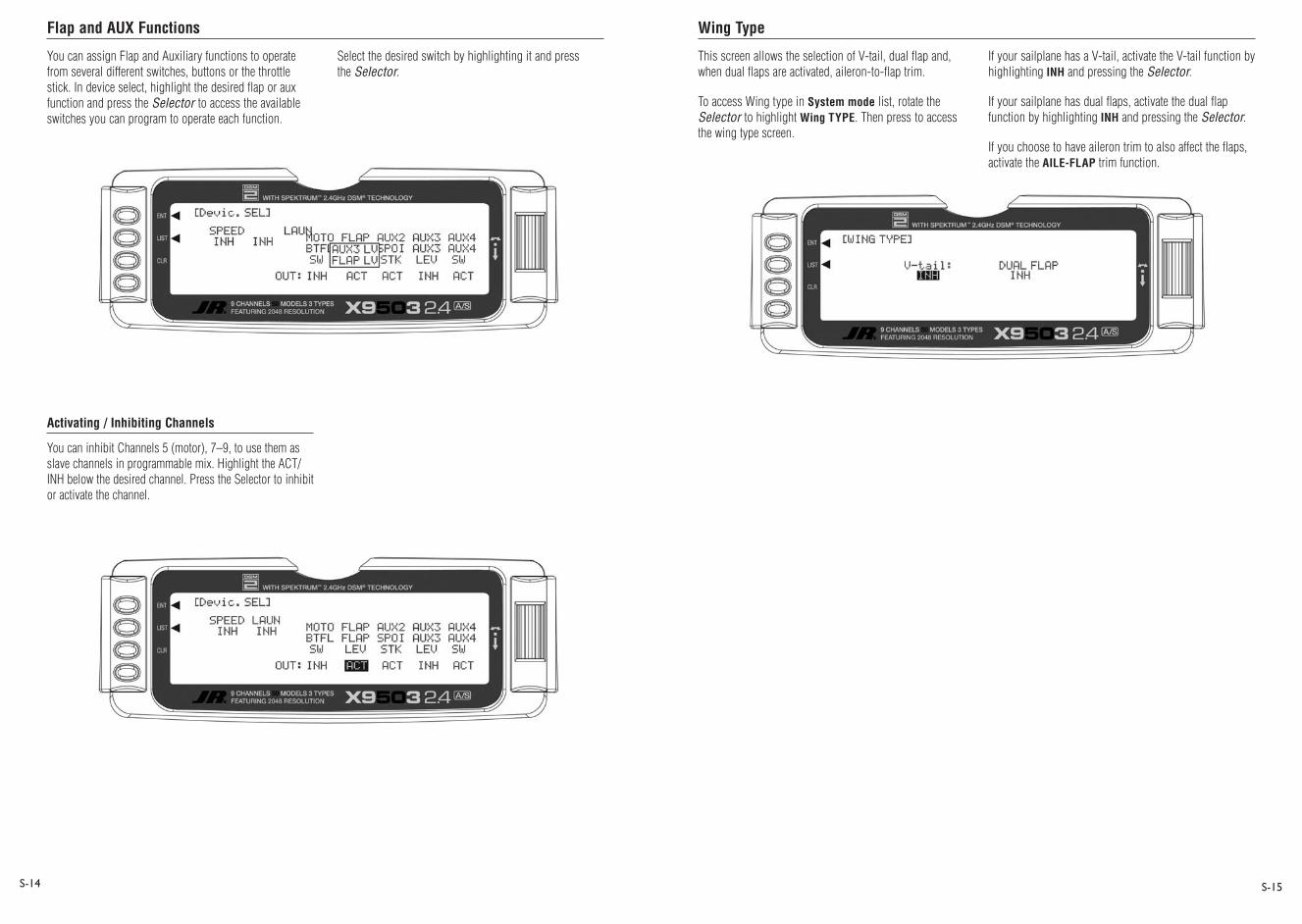
Flap and AUX Functions Wing Type
S-14 S-15
You can assign Flap and Auxiliary functions to operate from several different switches, buttons or the throttle stick. In device select, highlight the desired flap or aux function and press the Selector to access the available switches you can program to operate each function.
Select the desired switch by highlighting it and press the Selector.
Activating / Inhibiting Channels
You can inhibit Channels 5 (motor), 7–9, to use them as slave channels in programmable mix. Highlight the ACT/INH below the desired channel. Press the Selector to inhibit or activate the channel.
This screen allows the selection of V-tail, dual flap and, when dual flaps are activated, aileron-to-flap trim.
To access Wing type in System mode list, rotate the Selector to highlight Wing TYPE. Then press to access the wing type screen.
If your sailplane has a V-tail, activate the V-tail function by highlighting INH and pressing the Selector.
If your sailplane has dual flaps, activate the dual flap function by highlighting INH and pressing the Selector.
If you choose to have aileron trim to also affect the flaps, activate the AILE-FLAP trim function.

Elevator-to-Flap Mix Pg. S-21
Travel Adjust Pg. S-21
Dual Rate and Exponential Pg. S-18
Reversing Switch Pg. S-19
Sub-Trim Pg. S-20Differential Pg. S-22
Aileron-to-Flap Mix Pg. S-22
Function Mode
Camber Mix Pg. S-24
Aileron-to-Rudder Mix Pg. S-25
Butterfly Mix Pg. S-26
Flap Rate Pg. S-27
Motor Hold Pg. S-27Camber Adjust Pg. S-23
Programmable Curve Mix Pg. S-33
Programmable Mix Pg. S-28
Timer Pg. S-37
Timer Pg. S-36
Monitor Pg. S-38
Function Mode (continued)
[Trainer]MASTER NORMAL T.
ch THRO AILE ELEV RUDDSLAVMAST
S-16 S-17
Function mode contains the following screens:
Programs in function mode are more frequently used for both initial setup and at the field to change or optimize your aircraft’s flight characteristics and response.
To enter function mode, turn on the transmitter then press the ENT button. To enter the function list mode, press list mode after function mode has been selected.
D/R EXP110% 30110% 30125% 30125% 30125% 30125% 30
[D/R & EXP]◊0POS-0
POS-1
POS-2
AILEAUTOCRUI:0
LAUN:1LAND:2
[REV SW.]
LAI RAI ELE RUD MOT FLP AX2 AX3 AX4
REV.NORM
[Sub Trim]LAIL 0 RFLP D 225RAIL 0 LFLP U 225ELEV 0 AUX2 0RUDD 0 AUX3 0 AUX4 0
[TRVL ADJ.]LAIL L 81% R 81% RFLP +100% -100%RAIL L 81% R 81% LFLP U100% D106%ELEV D 59% U 50% AUX2 +100% -100%RUDD L 54% R 56% AUX3 +100% -100% AUX4 +100% -100%
[ELE≥FLP M]◊0-U DN UP OffsetPos1: 0% 0% 0Pos0: 0% 0% 0
AX4 BTF RUDPOS1POS0
[AIL≥FLP M]◊0
CRU LAU LND AX4 BTF RUDPOS1POS0
Pos0: 0% Pos1:+ 16%
[DIFFEREN.]AILE+60%+50%+20%
FLAP+40%+30%
0%
CRUISELAUNCHLAND
◊
FLAP LV Offset 0
[Flaprn MX] ◊U ≥FPRN ≥ELEVDN0%0%0%
DN0%0%0%
UP 0% 0% 0%
UP 0% 0% 0%
CRUILAUNCHLAND
◊
◊
◊
[AIL≥RUD M]◊LLeft
+ 40%+ 50%
0%
Right+ 40%+ 50%
0%
CRUISELAUNCHLAND
◊
[Butterfly]◊0 SPOI FPRN 0: 0% 1: 0%SPOI ELEV 0: 0% 1: 0%SPOI FLAP 0: +35% 1: 0%
SWSELECT
SPOI offset +170
[FLAP RATE]◊UUP DN 0% 0%
[MOTO.HOLD]◊OFF
Motor HOLDPos. 0.0%
CRU SPD THM AX4 BTF RUDONOFF
[FM Delay]Delay
1.5INH2.0
BREAK OFFACTINHINH
CRUISELAUNCHLAND ELEV
StickD 70%
◊
◊
◊
[PROG.Mix1] Point-0Point-1Point-2Point-3Point-4Point-5Point-6
0+ 15INH
+ 36INHINH
+ 44
SPOI≥ELEVSW SELECT
EXPOFF
IN 1 OUT 0 0 1 2 3 4 5 6
[PROG.Mix3]◊0FPRN≥FPRN Pos0 0%
0%Pos0 0% 0%
Offset 0
CRU LAU LND AX4 BTF RUDPOS1POS0
-
[TIMER] MODEL 1
INTEG-T
1:12
TIMER 1:DOWN-TTIME SW
10:00
TIMER 2:STOP-WTIM KEY
[MONITOR]MONI
LAILRAILELEVRUDD
MOTOFLAPAUX2AUX3AUX4
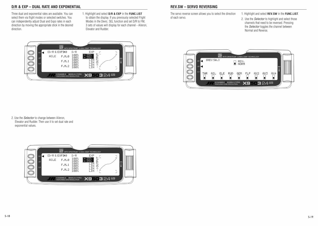
D/R & EXP – DUAL RATE AND EXPONENTIAL REV.SW – SERVO REVERSING
S-18 S-19
Three dual and exponential rates are available. You can select them via flight modes or selected switches. You can independently adjust Dual and Expo rates in each direction by moving the appropriate stick in the desired direction.
1. Highlight and select D/R & EXP in the FUNC.LIST to obtain the display. If you previously selected Flight Modes in the Devic. SEL function and set D/R to FM, 3 sets of values will display for each channel - Aileron, Elevator and Rudder.
2. Use the Selector to change between Aileron, Elevator and Rudder. Then use it to set dual rate and exponential values.
The servo reverse screen allows you to select the direction of each servo.
1. Highlight and select REV.SW in the FUNC.LIST.
2. Use the Selector to highlight and select those channels that need to be reversed. Pressing the Selector toggles the channel between Normal and Reverse.

SUB-TRIM TRVL. ADJ - TRAVEL ADJUST
Elevator-to-Flap Mix
S-20 S-21
Use Sub Trims to fine-tune the alignment of servo arms.
1. Highlight and select Sub-Trim in the FUNC.LIST to obtain the Display.
2. Highlight and select the channels where the sub trims must be adjusted. Once a channel is selected, rotate the Selector until the servo arm is in the desired position.
Note: Typical flap geometry requires that the sub-trim be significantly offset to provide adequate down flap throw. This issue exists because flaps typically have a large travel down (80 to 90 degrees) but very little travel up (less than 15 degrees). To achieve proper flap travel, you must set the right flap sub-trim at 225 down and the left flap sub-trim at 225
up, to start with. Then, when attaching the flap servo arms, be sure the spoiler stick is in the up position and camber lever in the middle position. Install the flap servo horns so they angle approximately 30˚ toward the trailing edge, then adjust the flap linkage such that the flaps are level.
Travel Adjust allows the independent adjustment of servo travel for each direction of servo travel.
1. Highlight and select TRVL ADJ. in the FUNC.LIST to obtain the Travel Adjust display.
2. Use the Selector to highlight and select each channel and adjust the travel in each direction by rotating the Selector. The direction of travel is changed by moving the stick/switch/lever back and forth.
Elevator-to-flap mix is normally used to give several degrees of down flap when up elevator is applied. This gives more pitch authority than elevator alone. Slope racers use this to improve high-speed turns and it allows increased maneuverability for tight thermal turns in thermal sailplanes. An offset is available that allows the programming of snap-flaps. With snap-flaps, no flap mixing occurs during small to medium up-elevator inputs.At about 80% up elevator, the flaps are mixed to give down flaps, causing greater up pitch authority. For more detail on setting up snap-flaps, see the setup guide on page S-66.
To access Elevator-to-flap mix, in Function Mode list, rotate the Selector until ELEFLP M is highlighted. Press the Selector to access the Elevator-to-Flap mix menu. Note that two elevator-to-flap mix values are available, Pos0 and Pos1. You can independently adjust the values up and down. You can also adjust the offset (the stick position where the mixing changes from up to down) in order to program snap-flaps. If you choose to program snap-flaps, the offset adjustment range is -200 to +200. Negative values move the offset in the up elevator direction. Switches at the bottom of the screen allow the selection of Pos0 or Pos1.
Note: Position 1 always has priority over position 0. Press the LIST button to return to the Function Mode screen.
30°
30°
B OTTOM C ONTR OL HOR N
TOP C ONTR OL HOR N

Aileron-to-Flap Mix
Differential
Camber Adjust
S-22 S-23
Aileron-to-flap mix causes the flaps to move in unison with the ailerons. This function gives added roll response by mixing ailerons to flaps such that the entire trailing edge functions as an aileron.
To access aileron-to-flap mix, in FUNC.LIST rotate the Selector until AILFLP M is highlighted. Press the Selector to access the Aileron-to-Flap mix.
Note: Two aileron-to-flap mix values are available—Pos0 and Pos1. Switches at the bottom of the screen allow the selection of Pos0 or Pos1.
Note that position 1 always has priority over position 0. Press the LIST button to return to the Function Mode screen.
Use Differential (typically more up aileron travel than down) to reduce adverse yaw and improve turning/handling characteristics. You can adjust aileron and flap differentials for each of the 5 flight modes.
To access Differential, in FUNC.LIST highlight DIFFEREN. Press the Selector to access the Aileron differential menu. Rotate the Selector to highlight the desired flight mode and aileron or flap value, then press the Selector to access that value. With the flight mode switch in the corresponding mode, give a full right aileron command and rotate the Selector to achieve the desired aileron or flap differential. Pressing the Selector will store the value. Press the LIST button to return to the Function Mode screen.
The camber adjust screen allows a delay of up to 2 seconds to be programmed to each of the 5 flight modes. This delay affects the flap, flaperon and elevator (and rudder and aileron if activated) presets such that when switching from one flight mode to another the servos don’t rapidly change to their intended preset position. An available break-off function in each flight mode bypasses the delay at a given programmed elevator stick position. This is useful during launch when you want to switch from launch flight mode to cruise for zoom and need to override the delay. In this case, you can set the break-off for slight down elevator in the cruise mode.
Note: In order for the camber adjustment to operate, you must program each flight mode in device select with different trim presets. See Device Select Pg. S-11 and Servo Monitor pg. S-39 for more details.
To access camber adjust, in FUNC.LIST highlight CAMBR ADJ. Press the Selector to access the Camber Adjust menu. Rotate the Selector to highlight the launch delay value, then press to access this value. Rotate the Selector to adjust the value, (from inhibit to 2 seconds are available). To access the break-off value, highlight the desired break-off flight mode then press the Selector. To access the elevator stick position, highlight ELEV Stick then press the Selector to access. Press the Selector to store the value. Press the LIST button to return to the Function Mode screen.

Camber Mix Aileron-to-Rudder Mix
S-24 S-25
Important: Camber mix values are based on a percentage of the Flap Rate value (see page S-27). If no values are programmed in flap rate (default setting), then camber mix values have no effect. You should program flap rate values before programming camber mix values. And remember, when you change flap rate values the travel of the camber mix settings is affected.
Camber mix allows the independent adjustment of flaperon and elevator with the lever the camber mix is assigned to for each of the flight modes in Device Select (pg. S-11). You can assign camber mix to the flap lever or Aux 3. The provided offset allows pilots to choose the neutral position for the side lever. You might prefer the lever’s neutral position in the center position when the trailing edge is at neutral (offset at 0). This offers the advantages of being able to add camber (trailing edge down) or reflex (trailing edge up) in each flight mode using the side lever. Some pilots prefer the neutral position in the lever up position (Offset +170).
To access camber mix, in FUNC.LIST highlight CAMBR MIX. Press the Selector to access the Camber Mix menu. Highlight the desired value then press the Selector to access. With the flight mode switch in the corresponding mode, move the programmed side lever to the appropriate position and adjust the value to the desired position. Press the Selector to store the value. Repeat the process for all flight modes. Press the LIST button to return to the Function Mode screen.
Note: The Offset value determines the point at which the side lever changes from the up value to the down value. If you want the lever neutral position in the middle, a 0 value is needed. This will allow up and down FPRN and ELEV values to be programmed. If an up lever position is desired, then use the offset value of +170. This only allows the down values to be operational.
Aileron-to-rudder mix causes the rudder to move in unison with ailerons. It reduces adverse yaw and improves the turning/handling characteristics. You can independently adjust aileron-to-rudder mix values right and left for each of the 5 flight modes.
To access Aileron-to-Rudder mix, in FUNC.LIST rotate the Selector until AILRUD M is highlighted. Press to access the aileron-to-rudder mix menu. Rotate the Selector to highlight the desired value corresponding to the flight mode and desired direction, then press the Selector to access that value. With the flight mode switch in the corresponding mode, give an aileron command and rotate the Selector to achieve the desired rudder value. Press the Selector to store the value. Press the LIST button to return to the Function Mode screen.

Butterfly Mix (Landing Flaps) Flap Rate
Motor Hold
S-26 S-27
The Butterfly Mix is the landing program that mixes the flaps, flaperons (ailerons as flaps) and elevator to the spoiler or throttle stick. Two values are available, Pos0 and Pos1. You can assign each to several different switches or flight modes. The provided offset allows the user’s preference for the neutral position (normally stick up).
To access the Butterfly menu, in FUNC.LIST highlight Butterfly. Press the Selector to access the Butterfly menu.
Note: The default setting for offset is at +170%.
With this setting, the flap’s neutral position (trailing edge level) occurs when the spoiler stick is in the full up position. If you locate the neutral position in the down position, the value would be –170%. Rotate the Selector to highlight SW select and press to access the available switches. The default setting is the BTF or butterfly switch. To access the various values, rotate the Selector to highlight them then depress to access the value. Move the spoiler stick to the full down position and adjust the value by rotating the Selector until the desired position is achieved. Press the Selector to store the value. You may wish to adjust the SPOIELEV, however, there is a curve mix in P-mix 1 that allows several points on a curve to be adjusted for flap-to-elevator mixing that we will be covering in programmable mix 1. Press the LIST button to return to the Function Mode screen.
Flap Rate allows the independent up and down adjustment of flaps with the lever that camber mix is assigned to. It is assigned to either the flap lever or Aux. 3 for each flight mode in Device Select (pg. S11). The lever-offset position is established in camber mix above, allowing pilots to choose the neutral position for the side lever. This offset is in effect in the flap rate menu (see Camber Mix for more details). Program these values before proceeding to the camber mix menu, as the camber mix values are based on a percentage of the flap values.
To access Flap Rate in FUNC.LIST highlight FLAP RATE. Press the Selector to access the Flap Rate menu. Highlight the desired value then press to access. With the flight mode switch in the corresponding launch mode, move the left side lever to the appropriate position and adjust the value to the desired flap position. Repeat this for all desired flight modes and flap positions. Press the LIST button to return to the Function Mode screen.
Note: This function is only available when the motor is programmed to the spoiler stick in the device select menu. See Device Select Pg. S-11.
The Motor Hold feature allows the spoiler stick to be used for multiple functions. For example, in launch mode you can use a proportional throttle for an electric motor and switch to another mode like landing and use the spoiler as landing flaps. You can use the motor hold function in conjunction with a programmable mix by mixing motor to an AUX channel. When the motor hold mix is on, the throttle hold program holds the throttle in the desired position (usually motor off).
To access Motor Hold in FUNC.LIST highlight MOTO. HOLD. Press the Selector to access the Motor Hold menu. Highlight desired flight mode or switch, then press the Selector to access on or off. Adjust the motor value to achieve the desired throttle position for that flight mode or switch. Press the LIST button to return to the Function Mode screen.

Programmable Curve Mix 1 (Programmed for Spoiler-to-Elevator Mix) PROG MIX - PROGRAMMABLE MIXERS
STANDARD PROGRAMMABLE MIXER - (Std. Prog Mixer)
S-28 S-29
Programmable mix 1 is a preprogrammed curve mix for spoiler-to-elevator. It works in conjunction with the butterfly mix pg. S27. On most sailplanes, deploying flaps causes the aircraft to pitch up. This pitching is non-linear and typically the airplane pitches up dramatically the first 25% of flap travel but becomes less dramatic during the 25% through 50% range and very little additional up pitching occurs from 75 to 100% flaps. Programmable mix 1 is a preprogrammed curve mix that mixes the spoiler stick (landing flaps) to the elevator.
To access programmable mix 1 in FUNC.LIST highlight PROG.Mix1. Press the Selector to access the Programmable mix 1 spoiler-to-elevator curve mix. Highlight the desired point then press the Selector to access the point’s value. Rotate the Selector to change the value. All points on the curve can be adjusted using this method. There are switches and flight modes to turn this curve on and off, but you should have this curve active anytime the butterfly (landing flaps) is active. All other functions in this mix are identical to curve mix 2, and this mix can be changed to any other master or slave. Press the LIST button to return to the Function Mode screen.
The X9503 2.4 system provides 2 Multi-Point programmable mixers, PROG.MIX1 & PROG.MIX2, and 4 Standard programmable mixers, PROG.MIX3 - PROG.MIX6. Programmable mixers are used whenever you want a channel (Slave) to react or move by providing input to another channel, or to simply cause a channel to move by moving a switch or lever.
Multi-Point Mixing provides the ability to define a customized “curve” of travel that the Slave channel follows as it reacts to the Master channel. It is different from Normal Mixing in that Normal Mixing results in a linear movement of the Slave channel in relation to the Master. With Multi-Point Mixing there are 7 points, including end points, along the travel of the Master channel that you can adjust to control the action of the Slave channel. You can input more or less travel in the same/opposite direction, providing non-linear mixing.
Mixing occurs when the pilot provides an input to the Master channel by moving a stick, switch, or lever. The transmitter automatically generates an input for the Slave channel based on your input to the Master channel and the parameters defined in the programmable mixer.
Mixes are programmable, allowing any of the 9 channels to be Master, Slave or both. You can program other mixing parameters and include the Slave channel’s direction of travel; the Slave channel’s amount of travel; the Offset (where the mix starts and changes direction) and the switches/levers/sticks used to turn a mixer on and off. All of these elements are adjustable in Programmable Mixers.
Note: Programmable Mix 1 defaults to SpoilerElevator mix. This program, when used in conjunction with Butterfly, allows for pitch compensation during landings. Programmable Mix 1 can be changed to use any master or slave channel if so desired.
The X9503 2.4 has 4 standard programmable mixers that allow for linear mixing of a Master channel to a Slave channel. The standard mixers are PROG.Mix3, 4, 5 and 6.
The mixer provides for 2 sets of mixing values named Pos0 and Pos1. If you program one set of values to 0%, you can turn the mixer On and Off with a stick, switch or lever. Each set of mixing values is comprised of 2 percentages to accommodate movement of the Master channel in both directions. This is shown in the
illustration below where there is an upper and lower percentage for both Pos0 and Pos1.
You can set a mixer always on by setting Pos0 values only and not selecting any switches to switch between the Pos0 and Pos1 values.

PROG MIX - PROGRAMMABLE MIXERS (continued) PROG MIX - PROGRAMMABLE MIXERS (continued)
S-30 S-31
Master Channel - (Std. Prog Mixer)
This is the Master channel that receives input from the pilot. The default for both the Master and the Slave channel is FPRN. To Select the Master channel, highlight and select this parameter for a list of channels. Select the Master channel from the list.
There are 4 channels that appear more than once. They are Flap, Aileron, Elevator and Rudder. These channels can be influenced by Dual Rate and Exponential settings, so they are included in the list twice - once where the D/R and EXP settings are in effect and again where D/R and EXP are ignored. The second time they are listed, there
is a special designator to indicate you can use them as a Master while bypassing any Dual Rate and Exponential settings associated with them. They appear with a “#” (pound sign) in front of the name - #FLP, #AIL, #ELE, and #RUD. When you select one of these as the Master, all D/R, EXP and Curve settings associated with the Master are ignored during the mixing operation. Instead, the mixer reads only the physical position of the stick to perform mixing.
A (+) behind the channel indicates a trim include function. By selecting a channel with the (+), the trim lever and any other program mixes to the master channel affect both the master and slave channels.
Slave Channel - (Std. Prog Mixer)
The Slave channel moves according to the input on the Master channel. The default for both the Master and the Slave is FPRN.
To choose the Slave channel, highlight and select this parameter to see the list of 9 available channels. Select the Slave channel from the list.
Current Switch Position - (Std. Prog Mixer)
Indicates the current switch position of the switch (if any) controlling the mixer.
Direction - (Std. Prog Mixer)
Each standard programmable mixer has two positions - Pos0 and Pos1 and each position has 2 percentages (upper and lower) to accommodate mixing when the Master is moved in both directions.
The direction indicator consists of a dotted and solid line next to the switch position on the top line of the display. The solid line indicates whether the upper or lower percentage is in effect for either Pos0 or Pos1, depending on which Position is currently selected.
As the Master channel moves above and below the Offset (where the mix turns on or changes direction), the solid bar moves between the top and bottom line. If for example, the switch is set so that Pos0 percentages are in effect and the master channel is moved below the Offset, the solid bar will be on the lower line meaning the lower percentage associated with Pos0 is in effect. When the master moves above the Offset, the solid bar moves to the top line indicating the upper percentage for Pos0 is in effect.
The Direction Indicator works the same way when you select the Pos1 values. It indicates the upper or lower value of Pos1 as you move the Master.
Pos0 Settings - (Std. Prog Mixer)
Each standard Programmable mixer can have two sets of mixing values - Pos0 and Pos1. Each set can have 2 percentages which control movement of the slave when the master is moved in both directions. You can select a switch to toggle between the Pos0 and Pos1 percentages.
The Pos0 settings determine how far, and in which direction, the slave channel moves when the master is moved above and below the Offset.
To enter Pos0 values, highlight and select Pos0, move the Master channel control (stick, lever or switch) in one direction and set the percentage. Then move the Master channel control in the other direction and set its value.
Pos1 Settings - (Std. Prog Mixer)
The Pos1 settings are identical to the Pos0 settings and determine how far, and in which direction, the slave channel moves when the master is moved above and below the offset.
To enter Pos1 values, highlight and select Pos1, move the Master channel control (stick, lever or switch) in one direction and set the percentage. Then move the Master channel control in the other direction and set its value.

PROG MIX - PROGRAMMABLE MIXERS (continued) MULTI-POINT PROGRAMMABLE MIXER
S-32 S-33
Offset - (Std. Prog Mixer)
The Offset parameter defines the position of the Master where the mixer changes directions. The Offset automatically defaults to a channel’s center position or 0 (zero). For example, if the Rudder is the Master, the Offset automatically defaults to the center stick position (no rudder input). Since the Offset is at the center, moving the rudder stick to the left of center causes a mix in one direction while moving the rudder stick to the right of center causes a mix in the other direction. Directions correspond to the upper and lower percentages for Pos0 and the upper and lower percentages of Pos1. The amount of mix and actual direction the slave moves is determined by the Pos0/Pos1 values. The Offset applies to both Pos0 and Pos1 settings.
You can change the Offset by highlighting and selecting Offset, then adjusting either a positive (+) or negative (-) value. A positive percentage moves the offset in one direction from center while a negative percentage moves the Offset in the other direction from center.
Available Switches - (Std. Prog Mixer)
There are 3 switches you can always use to switch between Pos0 and Pos1 settings. (If the upper and lower settings for Pos0 or Pos1 are left at 0%, you can turn the mixer on and off with the switch). They include the Rudder D/R switch, Butterfly Switch, Rudder D/R switch and the AUX4 switch. In addition, if Flight Modes are activated in the Devic.SEL function, then 5 more switches may be selected: Cruise, Speed, Thermal, Launch and Land, which correspond to the 3 positions of the Flight Mode switch.
To select a switch that will alternate between the Pos0 and Pos1 values, highlight and select the switch name and it will toggle between Pos0 and Pos1. Set the desired switch(es) to Pos1.
CLR Button - (Std. Prog Mixer)
Pressing the CLR button while a modifiable parameter is selected resets the parameter to its default value.
Note: Pressing the CLR button when either the Master or Slave is highlighted Inhibits the entire mixer, making it no longer functional.
LIST Button - (Std. Prog Mixer)
Press the LIST button to return to the FUNCTION List, or rotate the rotary selector until LST appears next to LIST and select it to return to the SYSTEM Menu.
ENT Button - (Std. Prog Mixer)
Pressing the ENT button returns to the Main Display.
TO INHIBIT A MIXER (TURN IT OFF ENTIRELY)
Highlight either the Master or Slave and press the CLR button to completely disable a mixer.
There are 2 Multi-Point Programmable Mixers in the GLID system. They are Prog.Mix1 and Prog.Mix2. They differ from the standard mixers in that they allow a non-linear mix response from the Master to the Slave. This is possible because the mixer uses 7 points to define how the slave channel moves as the Master is moved. As the
Master comes across each point, the Slave response can be defined in terms of deflection and direction independent of other point settings. This results in extreme flexibility in the movement of the Slave channel relative to the Master channel.
Master Channel - (Multi-Point Mixer)
This is the Master channel that receives input from the pilot. To select the Master channel, highlight and select this parameter to obtain a list of channels. Then select the Master channel from the list.
There are 4 channels that appear more than once. They are Flap, Aileron, Elevator and Rudder. Since these channels can be influenced by Dual Rate, Exponential, and Throttle Curve settings, they appear in the list twice - once where the D/R and EXP settings are in effect and again where the D/R and EXP settings are ignored. The second time they are listed, there is a special designator to indicate that these channels can also be used as a Master
while bypassing any Dual Rate and Exponential settings that may be associated with them. They are designated by a “#” (pound sign) in front of the name - #FLP, #AIL, #ELE, and #RUD. When one of these channels is selected as the Master, all D/R, EXP and Curve settings associated with the Master are ignored during the mixing operation. Instead, the mixer reads only the physical position of the stick to perform mixing.
A (+) behind the channel indicates a trim include function. By selecting a channel with the (+), the trim lever and any other program mixes to the master channel affects both the master and slave channels.

MULTI-POINT PROGRAMMABLE MIXER (continued) MULTI-POINT PROGRAMMABLE MIXER (continued)
S-34 S-35
Slave Channel - (Multi-Point Mixer)
This is the Slave channel that moves according to the program mix in relation to the Master channel.
To select the Slave channel, highlight and select this parameter to obtain a list of channels. Then select the Slave channel from the list of 9 channels.
Point Names/Numbers - (Multi-Point Mixer)
The points you can adjust are listed vertically by name and displayed by number along the bottom of the graph.
Change the value of a point by highlighting and selecting the point name and dialing-in the desired percentage.
Current Point Setting - (Multi-Point Mixer)
This list shows the setting for each of the 7 adjustable points (Point-0, 1, 2, 3, 4, 5, 6). The value of each point determines where the point is positioned vertically on the graph, which dictates the Slave servo position. You can set the values from -100 to +100. -100 is full deflection in one direction. +100 is full deflection in the other direction. A value of 0 indicates the Slave’s center or neutral position. The overall Travel settings of the slave channel are set in the TRVL ADJ. function.
A point value of INH can also be set for points 1, 2, 4, and 5. When set to INH the point takes on a value represented by the intersection of the cursor and the Curve/Line between the 2 adjacent points. For instance, if Point-1 is set to -67, Point-2 is set to INH and Point-3 is set to 0, then Point-2, which is inhibited, takes on a value of -34, which is midway between points 1 and 3.
Change the value for a point by highlighting and selecting the Point Name to the left of the point value then dialing-in the desired value.
Pressing the CLR button when a point value is highlighted resets the point to original settings. The
original settings are:
Point-0 -100
Point-1 INH
Point-2 INH
Point-3 0
Point-4 INH
Point-5 INH
Point-6 +100
Cursor - (Multi-Point Mixer)
The cursor shows the current Master channel position. When the Master channel is deflected fully in one direction, the cursor is to the extreme left over Point-0, when it is at neutral it is in the center over Point-3 and when it is fully deflected in the other direction the cursor is at the extreme right of the graph over Point-6.
The cursor moves across the 7 points as the Master is moved from one extreme to the other. Where the cursor intersects the Curve/Line over a given point defines the amount of Slave servo deflection, which is equal to the value assigned to the point. For example, if Point-2 is set to 30% then the servo deflects 30% from neutral when the Master is advanced so the cursor is over that point.
Curve/Line - (Multi-Point Mixer)
The Curve/Line is the line that results from connecting all of the points together based on their point values.
Graph - (Multi-Point Mixer)
The graph illustrates the mixing curve. The X-Axis (horizontal plane) represents Master channel movement. The Y-Axis (vertical plane) represents the Slave servo movement where the bottom half of the graph is one direction from neutral and the top portion of the graph is the other direction.
Points That Can Be Adjusted - (Multi-Point Mixer)
The points you can adjust are listed vertically by name and displayed by number along the bottom of the graph. Use the numbers along the bottom of the graph to determine which point(s) need adjustment.
Change the value of a point by highlighting and selecting the Point Name and dialing-in the desired percentage.
Exponential - (Multi-Point Mixer)
This parameter smoothes the Curve/Line between all of the points on the graph to provide a smoother mixing response. The default value is OFF. To turn it on and smooth the mixing curve, highlight and select OFF. It will toggle to ON.
Slave Channel Position - (Multi-Point Mixer)
The Slave servo position next to OUT at the bottom left of the display is expressed in values from -100 to +100, with 0 being neutral or center. It represents the servo travel corresponding to the present Master Channel position.
Note: When the mixer is switched OFF, the out value changes to OFF instead of displaying the Slave position. This is how to determine if the mixer is ON or OFF.
Master Channel Position - (Multi-Point Mixer)
The Master channel position shown on the bottom line of the display next to IN is expressed in values from 0 to 100 with 50 being the center or neutral position. It represents the present Master channel position.
Select Switch - (Multi-Point Mixer)
There are 3 switches that can be always used to switch between the Pos0 and Pos1 settings (if the upper and lower settings for Pos0 or Pos1 are left at 0% the mixer can be turned on and off with the switch). They include the Rudder D/R switch, Butterfly Switch, Rudder D/R switch and the AUX4 switch. In addition, if you activate Flight Modes in the Devic. SEL function, 5 more switches are available: Cruise, Speed, Thermal, Launch and Land, which correspond to the 3 positions of the Flight Mode switch.
To select a switch that will switch between the Pos0 and Pos1 values, highlight and select the switch name and it will toggle between Pos0 and Pos1. Set the desired switch(es) to Pos1.
CLR Button - (Multi-Point Mixer)
Pressing the CLR button while a modifiable parameter is selected resets the parameter to its default value.
Note: Pressing the CLR button when either the Master or Slave is highlighted Inhibits the entire mixer and it is no longer functional.
LIST Button - (Multi-Point Mixer)
Press the LIST button to return to the FUNCTION List, or rotate the rotary selector until LST appears next to LIST and select it to return to the SYSTEM Menu.
ENT Button - (Multi-Point Mixer)
Pressing the ENT button returns to the Main Display.
TO INHIBIT A MIXER (TURN IT OFF ENTIRELY)
Highlight either the Master or Slave and press the CLR button to completely disable a mixer.
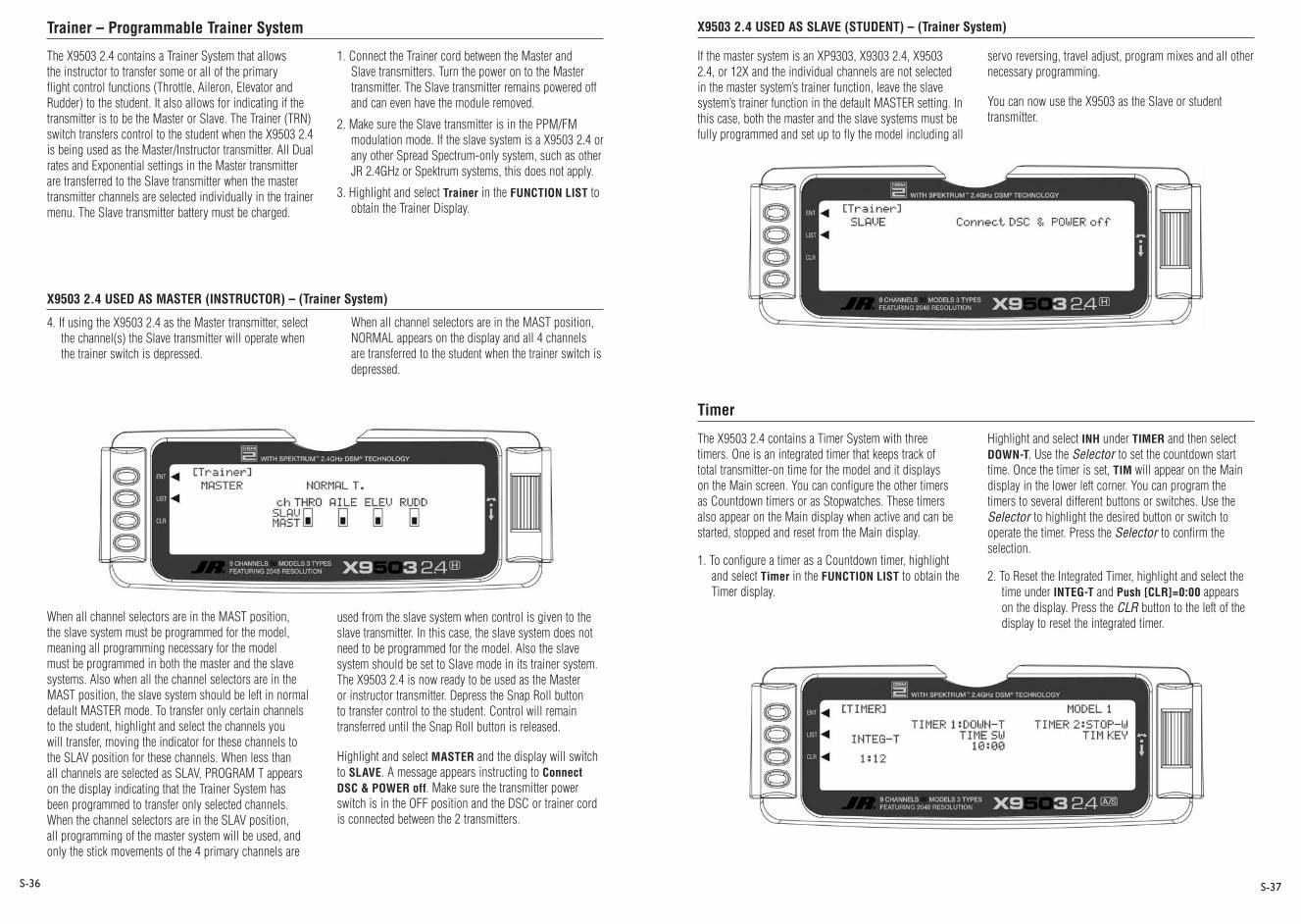
Trainer – Programmable Trainer System
X9503 2.4 USED AS MASTER (INSTRUCTOR) – (Trainer System)
X9503 2.4 USED AS SLAVE (STUDENT) – (Trainer System)
Timer
S-36 S-37
The X9503 2.4 contains a Trainer System that allows the instructor to transfer some or all of the primary flight control functions (Throttle, Aileron, Elevator and Rudder) to the student. It also allows for indicating if the transmitter is to be the Master or Slave. The Trainer (TRN) switch transfers control to the student when the X9503 2.4 is being used as the Master/Instructor transmitter. All Dual rates and Exponential settings in the Master transmitter are transferred to the Slave transmitter when the master transmitter channels are selected individually in the trainer menu. The Slave transmitter battery must be charged.
1. Connect the Trainer cord between the Master and Slave transmitters. Turn the power on to the Master transmitter. The Slave transmitter remains powered off and can even have the module removed.
2. Make sure the Slave transmitter is in the PPM/FM modulation mode. If the slave system is a X9503 2.4 or any other Spread Spectrum-only system, such as other JR 2.4GHz or Spektrum systems, this does not apply.
3. Highlight and select Trainer in the FUNCTION LIST to obtain the Trainer Display.
4. If using the X9503 2.4 as the Master transmitter, select the channel(s) the Slave transmitter will operate when the trainer switch is depressed.
When all channel selectors are in the MAST position, the slave system must be programmed for the model, meaning all programming necessary for the model must be programmed in both the master and the slave systems. Also when all the channel selectors are in the MAST position, the slave system should be left in normal default MASTER mode. To transfer only certain channels to the student, highlight and select the channels you will transfer, moving the indicator for these channels to the SLAV position for these channels. When less than all channels are selected as SLAV, PROGRAM T appears on the display indicating that the Trainer System has been programmed to transfer only selected channels. When the channel selectors are in the SLAV position, all programming of the master system will be used, and only the stick movements of the 4 primary channels are
used from the slave system when control is given to the slave transmitter. In this case, the slave system does not need to be programmed for the model. Also the slave system should be set to Slave mode in its trainer system. The X9503 2.4 is now ready to be used as the Master or instructor transmitter. Depress the Snap Roll button to transfer control to the student. Control will remain transferred until the Snap Roll button is released.
Highlight and select MASTER and the display will switch to SLAVE. A message appears instructing to Connect DSC & POWER off. Make sure the transmitter power switch is in the OFF position and the DSC or trainer cord is connected between the 2 transmitters.
If the master system is an XP9303, X9303 2.4, X9503 2.4, or 12X and the individual channels are not selected in the master system’s trainer function, leave the slave system’s trainer function in the default MASTER setting. In this case, both the master and the slave systems must be fully programmed and set up to fly the model including all
servo reversing, travel adjust, program mixes and all other necessary programming.
You can now use the X9503 as the Slave or student transmitter.
The X9503 2.4 contains a Timer System with three timers. One is an integrated timer that keeps track of total transmitter-on time for the model and it displays on the Main screen. You can configure the other timers as Countdown timers or as Stopwatches. These timers also appear on the Main display when active and can be started, stopped and reset from the Main display.
1. To configure a timer as a Countdown timer, highlight and select Timer in the FUNCTION LIST to obtain the Timer display.
Highlight and select INH under TIMER and then select DOWN-T. Use the Selector to set the countdown start time. Once the timer is set, TIM will appear on the Main display in the lower left corner. You can program the timers to several different buttons or switches. Use the Selector to highlight the desired button or switch to operate the timer. Press the Selector to confirm the selection.
2. To Reset the Integrated Timer, highlight and select the time under INTEG-T and Push [CLR]=0:00 appears on the display. Press the CLR button to the left of the display to reset the integrated timer.
When all channel selectors are in the MAST position, NORMAL appears on the display and all 4 channels are transferred to the student when the trainer switch is depressed.

Monitor
S-38 S-39
To access the servo monitor, in FUNC.LIST rotate the Selector until MONITOR is highlighted. Press the Selector to access the Monitor menu then press the Selector again to access the camber digital preset screen. To adjust the presets, move the flight mode switch to the launch mode (up) position. Adjust the preset positions via the flap trim, auxiliary trim and elevator trims on the transmitter. The values will be displayed in the screen and then memorized for that flight mode. If you wish to have these preset values be fixed (not active in flight), once you establish the values return to the Trim Step screen in the system mode and reduce the value of the desired channel to 0. The preset values for all flight modes will be stored and no longer accessible with the digital trims.
The X9503 2.4 offers tremendous flexibility allowing nearly infinite setup options. The available five flight modes allow virtually every parameter to be independently adjusted in each flight mode. You can program camber adjustment, landing flaps, motor control, flight modes with all their options, programmable mixes, dual rates and even the two timers to several different levers and/or switches, allowing personal customization preferences.
Following is a step-by-step programming guide that will familiarize you with a typical setup procedure. We recommend following this setup guide during your first attempts at programming, as it will familiarize you with the available functions and how flight modes operate. Later you can customize this setup, adding more flight modes, changing function locations, etc. to meet your specific needs and preferences.
The following setup utilizes three flight modes (Launch, Cruise and Land), which are selected using the left 3-position switch on the face of the transmitter. Trailing edge camber adjustment will be assigned to the left side lever in the launch and cruise mode. Butterfly (landing
flaps) will be assigned to the spoiler stick (throttle stick) to be active in all flight modes. This is the setup I personally use and believe this program offers a great base for sailplane pilots to develop their own setups from.
Programming a 6-Channel Sailplane by Engineering Manager John Adams
50FEATURING 2048 RESOLUTION
Spoiler stick Butterfly (landing flaps)
Left 3-position switch Flight Modes- Launch
Cruise Land
Left side lever Camber adjustment

Step #1 Servo Assignment
S-40 S-41
Note on installing flap servos: Typical flap geometry requires that the servo arms be significantly offset to provide adequate down flap throw. This issue exists because flaps typically have a large travel down (80 to 90 degrees) but very little up travel (less than 15 degrees). To achieve proper flap travel, it is necessary that the right flap sub-trim is set at 225 down and the left flap sub trim is set at 225 up as a starting point. Then when installing the flap servo arms, be sure the spoiler stick is in the up position and camber lever in the middle position. Install the flap servo horns so they angle approximately 30 degrees toward the trailing edge (if the flaps have the control horn on the bottom of the flap) or 30 degrees toward the leading edge (if the flap control horn is on top of the flap) then adjust the flap linkage so the flaps are level. See Sub-Trim on Page S-20 for more details.
Channel Assignment
Important: In glider mode, the channel assignment (servo lead positions in the receiver) of the X9503 2.4 is different than previous JR radios. This new channel assignment has two important advantages:
• It allows you to use a 6-channel receiver to control the 6 functions commonly found on full-function sailplanes.
• It locates commonly mixed channels, like right and left ailerons, right and left flaps, rudder and elevator for V-tail, next to each other in the data stream minimizing synchronizing delay issues.
Install the servos in the correct location in the receiver per the chart and illustration below.
Servo Channel # Receiver Position
Left Aileron 1 Throttle
Right Aileron 2 Aileron
Elevator 3 Elevator
Rudder 4 Rudder
Right Flap 5 Gear
Left Flap 6 Flap/ Aux. 1
ON
OFF
4N11004.8V 1100mAh
JAPAN REMOTE CONTROL CO., LTD.
®
Note: Position the flap and aileron servos so their output shafts face outward toward the wing tips.
30°
30°
B OTTOM C ONTR OL HOR N
TOP C ONTR OL HOR N
Left AileronRight AileronElevator
RudderRight FlapLeft Flap
Switch
Receiver Battery
Charge Connection
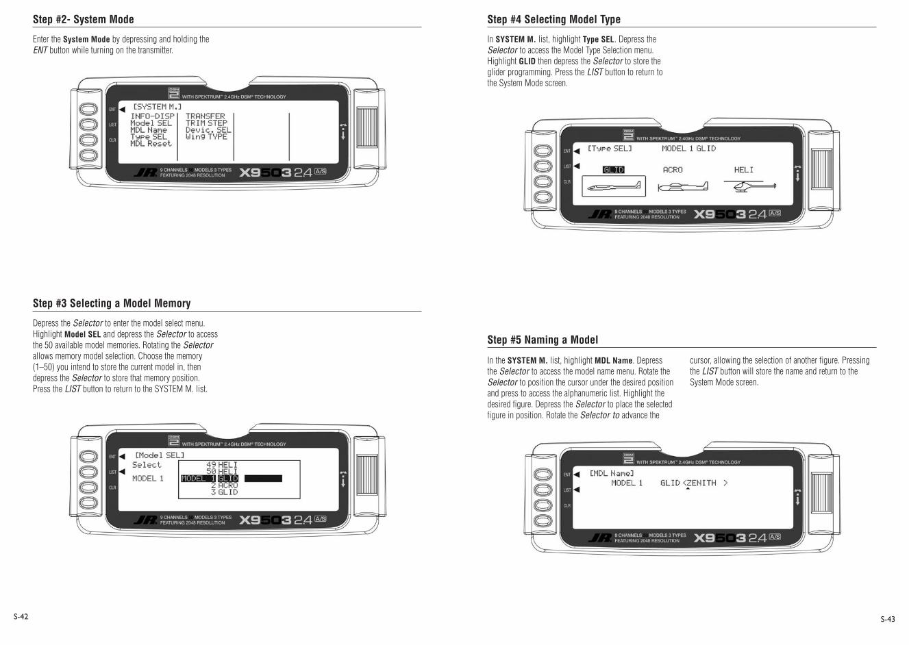
Step #2- System Mode
Step #3 Selecting a Model Memory
Step #4 Selecting Model Type
Step #5 Naming a Model
S-42 S-43
Enter the System Mode by depressing and holding the ENT button while turning on the transmitter.
Depress the Selector to enter the model select menu. Highlight Model SEL and depress the Selector to access the 50 available model memories. Rotating the Selector allows memory model selection. Choose the memory (1–50) you intend to store the current model in, then depress the Selector to store that memory position. Press the LIST button to return to the SYSTEM M. list.
In SYSTEM M. list, highlight Type SEL. Depress the Selector to access the Model Type Selection menu. Highlight GLID then depress the Selector to store the glider programming. Press the LIST button to return to the System Mode screen.
In the SYSTEM M. list, highlight MDL Name. Depress the Selector to access the model name menu. Rotate the Selector to position the cursor under the desired position and press to access the alphanumeric list. Highlight the desired figure. Depress the Selector to place the selected figure in position. Rotate the Selector to advance the
cursor, allowing the selection of another figure. Pressing the LIST button will store the name and return to the System Mode screen.
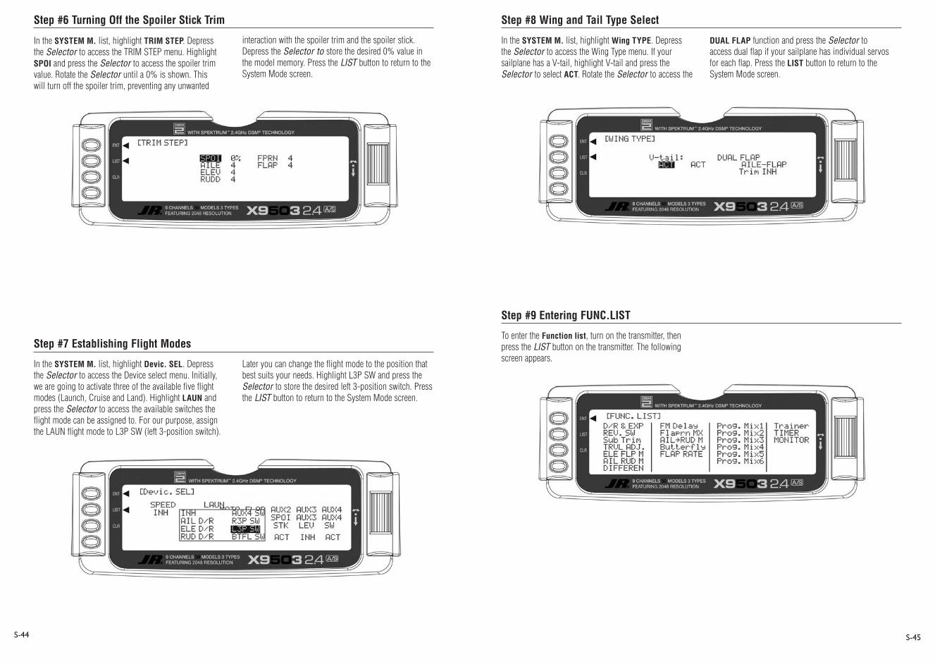
Step #6 Turning Off the Spoiler Stick Trim
Step #7 Establishing Flight Modes
Step #8 Wing and Tail Type Select
Step #9 Entering FUNC.LIST
S-44 S-45
In the SYSTEM M. list, highlight TRIM STEP. Depress the Selector to access the TRIM STEP menu. Highlight SPOI and press the Selector to access the spoiler trim value. Rotate the Selector until a 0% is shown. This will turn off the spoiler trim, preventing any unwanted
interaction with the spoiler trim and the spoiler stick. Depress the Selector to store the desired 0% value in the model memory. Press the LIST button to return to the System Mode screen.
In the SYSTEM M. list, highlight Devic. SEL. Depress the Selector to access the Device select menu. Initially, we are going to activate three of the available five flight modes (Launch, Cruise and Land). Highlight LAUN and press the Selector to access the available switches the flight mode can be assigned to. For our purpose, assign the LAUN flight mode to L3P SW (left 3-position switch).
Later you can change the flight mode to the position that best suits your needs. Highlight L3P SW and press the Selector to store the desired left 3-position switch. Press the LIST button to return to the System Mode screen.
In the SYSTEM M. list, highlight Wing TYPE. Depress the Selector to access the Wing Type menu. If your sailplane has a V-tail, highlight V-tail and press the Selector to select ACT. Rotate the Selector to access the
DUAL FLAP function and press the Selector to access dual flap if your sailplane has individual servos for each flap. Press the LIST button to return to the System Mode screen.
To enter the Function list, turn on the transmitter, then press the LIST button on the transmitter. The following screen appears.

Step #10 Servo Reversing Step #11 Sub-Trim
S-46 S-47
In FUNC.LIST list, highlight REV. SW. Press the Selector to access the reverse switch menu. Highlight the desired channel then press the Selector to reverse the selected channel’s direction. Check the direction of all
servos and reverse as necessary. Press the LIST button to return to the Function Mode screen.
In FUNC.LIST rotate the Selector until Sub-Trim is highlighted. Press the Selector to access the Sub-Trim menu. Highlight the desired channel, then press the Selector to change the sub-trim value of that channel. Set the sub-trim for all functions in the neutral position. (see flap note below). Press the LIST button to return to the Function Mode screen.
Note: Typical flap geometry requires the sub-trim be significantly offset to provide adequate down flap throw. This issue exists because flaps typically have a large travel down (80 to 90 degrees) but very little travel up (less than 15 degrees). To achieve proper flap travel, it is necessary that the right flap sub-trim be set at 225 down and the left flap sub-trim be set
at 225 up as a starting point. Then, when attaching the flap servo arms, be sure the spoiler stick is in the up position and camber lever is in the middle position. Install the flap servo horns so they are angled approximately 30% toward the trailing edge, then adjust the flap linkage so the flaps are level.
30°
30°
B OTTOM C ONTR OL HOR N
TOP C ONTR OL HOR N

Step #12 Travel Adjust
Step #13 Butterfly (Landing Flaps)
Step #14 Spoiler to Elevator Curve Mix (Programmable Mix 1)
S-48 S-49
In FUNC.LIST highlight TRVL ADJ. Press the Selector to access the Travel Adjust menu. Highlight the desired channel then press the Selector to change the sub-trim value of that channel. Moving the applicable control stick or switch changes the direction in
In FUNC.LIST highlight Butterfly. Press the Selector to access the Butterfly menu. Note the default setting for offset is at +170%. With this setting, the flap’s neutral position (trailing edge level) occurs when the spoiler stick is in the full up position. Highlight SW select and press the Selector to access the available switches. Rotate the Selector to select the BTF switch and press the Selector to move the switch to Pos0. Be sure all switches in this screen are set at zero. This is necessary to allow the Butterfly function to always be on. Highlight SPOIFLAP 0 then depress the Selector to access the spoiler-to-flap value. Move the spoiler stick to the full down position and adjust the value by rotating the Selector until the desired
down flap position is achieved. Press the Selector to store the flap value then rotate the Selector to access the SPOIFPRN 0 function. Depress the Selector to access this value and with the spoiler stick in the low position, adjust the flaperons (ailerons as flaps) to the desired position. You may wish to adjust the SPOIELEV at this time, however, there is a curve mix in P-mix 1 that allows several points on a curve to be adjusted for flap-to-elevator mixing covered in Step 15 below. Press the LIST button to return to the Function Mode screen.
On most sailplanes, deploying flaps causes the aircraft to pitch up. This pitching is non-linear and typically the
which the travel adjustment is made (right/ left, up/down). Set the travel adjust for all functions except flaps at this time. Press the LIST button to return to the Function Mode screen.
airplane pitches up dramatically the first 25% of flap travel but becomes less dramatic during the 25% through 50% range, and very little additional up pitching occurs from 75 to 100% flaps. The X9503 2.4 incorporates a preprogrammed curve mix that mixes the spoiler stick (landing flaps) to the elevator.
In FUNC.LIST highlight PROG Mix1. Press the Selector to access the Programmable mix 1 spoiler-to-elevator curve mix. Highlight the desired point then press the Selector to access the point’s value. Rotate the Selector to change the value. You can adjust all points on the curve using this method. The curve below shows the typical values needed for a common performance sailplane. Press the LIST button to return to the Function Mode screen.
Setting Up Flight Modes
Up to this point we have established the foundational programming common to all flight modes. Now we will focus on the specifics of setting up each individual flight mode.
We will individually program the following parameters for each of the selected flight modes (Launch, Cruise, Land).
• Dual and Exponential rates for Aileron, Elevator and Rudder
• Preset positions for the Camber, Flaperon and Elevator
• Elevator-to-Flap Mixes• Aileron-to-Flap Mixes• Aileron Differential• Flight Mode Delay• Camber Adjustment• Aileron-to-Rudder Mixes• Spoiler-to-Elevator Curve Mix (elevator
compensation)
Launch Mode Setup
In Step #8, Establishing Flight Modes, flight modes are programmed to operate from the left front 3-position switch. To select Launch mode, move the left 3-position switch in the up position. In the main (info) screen LAUNCH appears in the upper portion of the display when Launch mode is selected. When making programming changes/adjustments in Launch mode, this 3-position switch must remain in the upper position during the process to allow the results of those adjustments to be seen on the model.

Step #15 Launch Presets Step #16 Dual Rate and Exponential
Step #17 Elevator-to-Flap Mix
S-50 S-51
The X9503 2.4 offers a sophisticated program that allows easy preset trim positions for the elevator, flaps, flaperons (and even the aileron and rudder if you choose). The system can remain active in flight, allowing you to fine-trim presets in each flight mode or be locked in so they cannot be altered in flight. Flight mode presets are automatically selected via the flight mode switch and are adjusted with the digital elevator trim, the digital flap trim and the digital auxiliary trim (flaperon). While the presets are adjusted via the digital trims, their positions are recorded in the servo monitor.
To access the servo monitor, in FUNC.LIST highlight MONITOR. Press the Selector to access the Monitor menu then press the Selector again to access the camber digital preset screen. To adjust the presets move the flight mode switch to the launch mode (up) position. Adjust the preset positions via the flap trim, auxiliary trim and elevator trim on the transmitter. The values will display in the screen and then will be memorized for that flight mode. If you want these preset values to be fixed (not active in flight) once the values are established, return to the Trim Step screen in the system mode and reduce the value of the desired channel to 0. The preset values for all flight modes will be stored and no longer accessible with the digital trims.
In FUNC.LIST, highlight D/R & EXP. Press the Selector to access the Dual Rate and Exponential menu. Highlight the channel (aile, elev or rudd) then press the Selector to select the channel you wish to adjust the dual and expo rates for. Rotate to select then press the Selector to store the desired channel.
Note that three D/R and EXPO positions (values) are available (Pos0, 1 and 2). Under AUTO on the right of the screen, highlight LAUN and press the Selector. Select Pos0 as the active position for the launch mode by rotating the Selector then press the Selector when Pos0 is highlighted. This automatically accesses dual rate and expo values programmed into position 0 whenever
launch mode is selected. Now rotate the Selector to Pos0 and highlight the D/R values. Rotate the Selector to change these values. Displace the aileron stick right or left to independently adjust the dual rate in each direction. Depress the Selector to store the desired D/R values. Rotate the Selector to the EXP Pos0 values and adjust these values in the same manner pressing the Selector to store the desired value.
Now go back to channel and repeat for the two remaining channels. Press the LIST button to return to the Function Mode screen.
This function is normally not used in launch mode. It will be addressed in setting up the Cruise mode below.

Step #18 Aileron-to-Flap
Step #19 Aileron Differential
Step #20 Flap Rate, Camber Mix and Camber Adjust
S-52 S-53
This function gives added roll response by mixing ailerons to flaps so the entire trailing edge functions as an aileron. In FUNC.LIST highlight AILFLP M. Press the Selector to access the Aileron-to-flap mix. Highlight LND then press the Selector selecting Pos1. Highlight Pos1 above and press the Selector to access the aileron-to-flap values. With the flight mode switch in the upper
launch position, move the aileron control stick full right and hold while adjusting the aileron-to-flap value by rotating the Selector achieving the desired mix. Press the LIST button to return to the Function Mode screen.
In FUNC.LIST highlight DIFFEREN. Press the Selector to access the Aileron differential menu. Highlight the launch aileron value then press the Selector to access that value. With the flight mode switch in the upper launch mode, give a full right aileron command and rotate
the Selector to achieve the desired aileron differential for launch. Press the Selector to store the value. Now highlight the launch flap value and adjust it to the desired position. Press the LIST button to return to the Function Mode screen.
Many pilots prefer to have variable camber adjustment during launch. This enables adjustments at the last minute or even during launch, based on wind and winch (launching) conditions.
Important: The flaperon and elevator values in the camber mix menu are based on a percentage of the programmed flap rate. The flap rates are defaulted to 0% from the factory, so flaperon and elevator mix values have no effect until the flap rate values are set. Because of this, it’s mandatory to first adjust the flap rates before adjusting the flaperon and elevator camber mixes. Also remember that changing the flap rate values also affects the flaperon and elevator camber mix.
Flaperon Mix
In FUNC.LIST highlight Flaprn MX. Press the Selector to access the Flap Rate menu. Highlight the launch down value then press the Selector to access this value. With the flight mode switch in the upper launch mode, move the left side lever to the lower most position and adjust the down value to the desired flap position. Now, with the flight mode switch in the upper launch mode, move the left side lever to the uppermost position and adjust the up value to the desired flap position. Press the LIST button to return to the Function Mode screen.

Step #21 Flap Rate, Camber Mix and Camber Adjust (continued) Step #22- Aileron-to-Rudder Mix
S-54 S-55
Flaperon Mix
Note: Flap rate must be set before camber mix.
In FUNC.LIST highlight Flaprn MX. Press the Selector to access the Camber Mix menu. Highlight the launch FPRN down value then press the Selector to access this value. With the flight mode switch in the upper launch mode, move the left side lever to the lowermost position and adjust the down value to the desired flaperon
Flaperon Mix Delay
The camber adjust menu allows the programming of a delay from 0 to 2 seconds. This delay affects the flap, flaperon and elevator presets when switching from one flight mode to another. When inhibited, no delay occurs and the servo immediately transitions from one preset trim position to another when the flight modes are switched. With a delay programmed the transition is smooth relative to the delay time. A break-off function is available that you can program to override the delay, based on a selected elevator stick position. For this setup, we will program a 1.0 second delay for Launch.
position. Press the Selector to store the value. Now with the flight mode switch in the upper launch mode, move the left side lever to the uppermost position and adjust the up value to the desired flaperon position and store by pressing the Selector. Repeat the process for the up and down elevator camber mix. Press the LIST button to return to the Function Mode screen.
In FUNC.LIST highlight FM Delay. Press the Selector to access the Camber Adjust menu. Highlight the launch delay value then press the Selector to access this value. Rotate the Selector to adjust the value to 1.0s (seconds), Press the Selector to store the value. Press the LIST button to return to the Function Mode screen.
In FUNC.LIST highlight AILRUD M. Press the Selector to access the Aileron-to-Rudder mix menu. Highlight the launch left value then press the Selector to access that value. With the flight mode switch in the upper launch mode, give a full left aileron command and rotate the Selector to achieve the desired left rudder throw. Press the Selector to store the value. Now highlight the launch right value and adjust it to the desired position. Press the LIST button to return to the Function Mode screen.
Setting Up Cruise Mode
In Step #8, Establishing Flight Modes, flight modes were programmed to operate from the left front 3-position switch. To select Cruise mode, move the left 3-position switch to the middle position. In the main (info) screen CRUISE appears in the upper portion of the display when Cruise mode is selected. When making programming changes/adjustments in Cruise mode, this 3-position switch must remain in the middle position during the process to allow the results of those adjustments to be seen on the model.

Step #23 Cruise Pre-sets
Step #24 Dual Rate and Exponential
Step #25 Elevator-to-Flap Mix
S-56 S-57
In FUNC.LIST, highlight D/R & EXP. Press the Selector to access the Dual Rate and Exponential menu. Highlight the channel (aile, elev or rudd) then press the Selector to select the desired channel you wish to adjust the dual and expo rates for. Rotate to select then press the Selector to store the desired channel.
Note: Three D/R and EXPO positions (values) are available (Pos0, 1 and 2).
Under AUTO on the right of the screen, highlight CRUI and press the Selector. Select Pos1 as the active position for the cruise mode by rotating the Selector then pressing it when Pos1 is highlighted. This will automatically access dual rate and expo values programmed into position 1 whenever cruise mode is selected. Now rotate the Selector to Pos1 and highlight the D/R values. Rotate the Selector to change these values. Displace the aileron stick right or left to independently adjust the dual rate in each direction. Depress the Selector to store the desired D/R values. Rotate the Selector to the EXP Pos1 values and adjust these values in the same manner, pressing the Selector to store the desired value.
Now go back to channel and repeat for the two remaining channels. Press the LIST button to return to the Function Mode screen.
This function is normally not used in cruise mode; however, it is active and all trim adjustments will be automatically stored when cruise mode is selected.
In Function Mode list, highlight ELEFLP M. Press the Selector to access the Elevator-to-Flap mix menu. Note that two elevator-to-flap mix values are available, Pos0 and Pos1, and the elevator-to-flap values can be independently adjusted up and down. Also, you can adjust the offset (the stick position where the mixing changes from up to down). This offset allows the programming of snap-flaps, a common sailplane function that gives greater full up elevator pitch authority for tighter turns. With snap-flaps, no flap mixing occurs during small to medium up elevator inputs, but at about 80% up elevator, the flaps are mixed to give down flaps, causing greater up pitch authority.
Highlight CRU (cruise mode) at the bottom of the screen and depress the Selector to select Pos1. If you choose to program snap-flaps, highlight Offset Pos1 and depress the Selector to access this value. A 0 value locates the offset position when the elevator is centered. The adjustment range is -200 to +200. Negative values move the offset in the up elevator direction. Set a value of –100 to start, as this will locate the offset at 80% up elevator. Press the Selector to store this offset value. Highlight Pos1 UP and depress the Selector to access the position 1 up elevator mixing. With the 3-position switch in the middle (cruise) position, give a full up elevator command and hold while adjusting the Pos1 up value until the desired down flap position is achieved. Press the LIST button to return to the Function Mode screen.
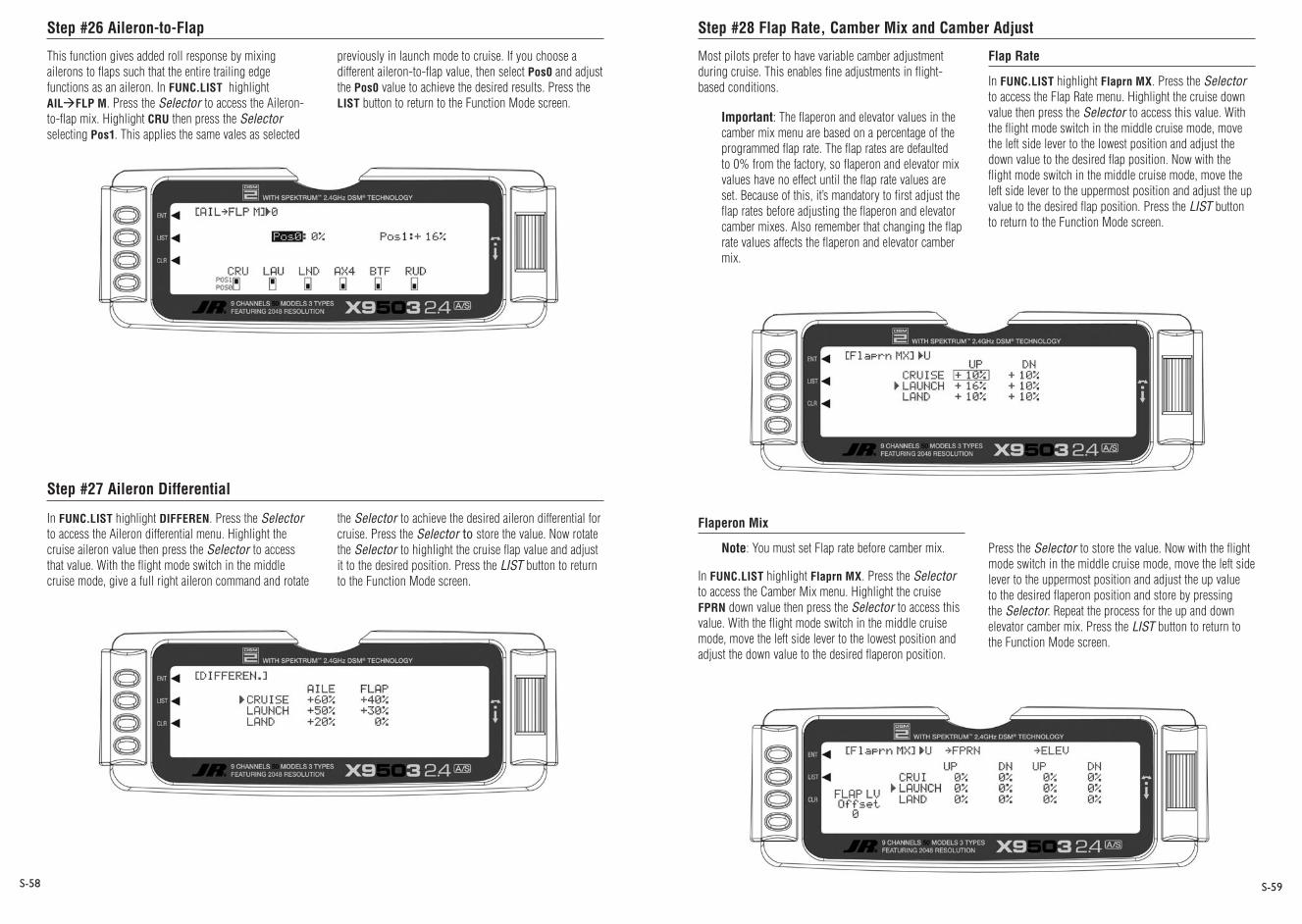
Step #26 Aileron-to-Flap
Step #27 Aileron Differential
Step #28 Flap Rate, Camber Mix and Camber Adjust
S-58 S-59
This function gives added roll response by mixing ailerons to flaps such that the entire trailing edge functions as an aileron. In FUNC.LIST highlight AILFLP M. Press the Selector to access the Aileron-to-flap mix. Highlight CRU then press the Selector selecting Pos1. This applies the same vales as selected
In FUNC.LIST highlight DIFFEREN. Press the Selector to access the Aileron differential menu. Highlight the cruise aileron value then press the Selector to access that value. With the flight mode switch in the middle cruise mode, give a full right aileron command and rotate
previously in launch mode to cruise. If you choose a different aileron-to-flap value, then select Pos0 and adjust the Pos0 value to achieve the desired results. Press the LIST button to return to the Function Mode screen.
the Selector to achieve the desired aileron differential for cruise. Press the Selector to store the value. Now rotate the Selector to highlight the cruise flap value and adjust it to the desired position. Press the LIST button to return to the Function Mode screen.
Most pilots prefer to have variable camber adjustment during cruise. This enables fine adjustments in flight-based conditions.
Important: The flaperon and elevator values in the camber mix menu are based on a percentage of the programmed flap rate. The flap rates are defaulted to 0% from the factory, so flaperon and elevator mix values have no effect until the flap rate values are set. Because of this, it’s mandatory to first adjust the flap rates before adjusting the flaperon and elevator camber mixes. Also remember that changing the flap rate values affects the flaperon and elevator camber mix.
Flap Rate
In FUNC.LIST highlight Flaprn MX. Press the Selector to access the Flap Rate menu. Highlight the cruise down value then press the Selector to access this value. With the flight mode switch in the middle cruise mode, move the left side lever to the lowest position and adjust the down value to the desired flap position. Now with the flight mode switch in the middle cruise mode, move the left side lever to the uppermost position and adjust the up value to the desired flap position. Press the LIST button to return to the Function Mode screen.
Flaperon Mix
Note: You must set Flap rate before camber mix.
In FUNC.LIST highlight Flaprn MX. Press the Selector to access the Camber Mix menu. Highlight the cruise FPRN down value then press the Selector to access this value. With the flight mode switch in the middle cruise mode, move the left side lever to the lowest position and adjust the down value to the desired flaperon position.
Press the Selector to store the value. Now with the flight mode switch in the middle cruise mode, move the left side lever to the uppermost position and adjust the up value to the desired flaperon position and store by pressing the Selector. Repeat the process for the up and down elevator camber mix. Press the LIST button to return to the Function Mode screen.

Step #29 Flap Rate, Camber Mix and Camber Adjust (continued) Step #30 Aileron-to-Rudder Mix
S-60 S-61
Flaperon Mix Delay
The camber adjust menu allows the programming of a delay from 0 to 2 seconds. This delay affects the flap, flaperon and elevator presets when switching from one flight mode to another. When inhibited, no delay occurs and the servo immediately transitions from one preset trim position to another when the flight modes are switched. With a delay programmed, the transition is smooth relative to the delay time. You can program the available break-off function to override the delay, based on a selected elevator stick position. For this setup, we will program a 1.0 second delay for cruise.
In FUNC.LIST highlight FM Delay. Press the Selector to access the Camber Adjust menu. Highlight the cruise delay value then press the Selector to access this value. Rotate the Selector to adjust the value to 1.0s (seconds). Press the Selector to store the value. Press the LIST button to return to the Function Mode screen.
In FUNC.LIST highlight AILRUD M. Press the Selector to access the Aileron-to-rudder mix menu. Highlight the cruise left value then press the Selector to access that value. With the flight mode switch in the middle cruise mode, give a full left aileron command and rotate the Selector to achieve the desired left rudder throw. Press the Selector to store the value. Now rotate the Selector to highlight the launch right value and adjust it to the desired position. Press the LIST button to return to the Function Mode screen.
Setting Up Land Mode
In Step #8, Establishing Flight Modes, flight modes were programmed to operate from the left front 3-position switch. To select Land mode, move the left 3-position switch to the down position. In the main (info) screen LAND appears in the upper portion of the display when Land mode is selected. When making programming changes/adjustments in Land mode, this 3-position switch must remain in the lower position during the process to allow the results of those adjustments to be seen on the model.

Step #31 Land Presets Step #32 Dual Rate and Exponential
S-62 S-63
The X9503 2.4 offers a sophisticated program with easy preset trim positions for the elevator, flaps, flaperons (and even the aileron and rudder if you choose). The system can remain active in flight allowing you to fine-trim presets in each flight mode or can be locked in so they cannot be altered in flight. Flight mode presets are automatically selected via the flight mode switch and are adjusted with the digital elevator trim, the digital flap trim and the digital auxiliary trim (flaperon). While the presets are adjusted via the digital trims, their positions are recorded in the servo monitor.
To access the servo monitor, in FUNC.LIST highlight MONITOR. Press the Selector to access the Monitor menu then press the Selector again to access the camber digital preset screen. To adjust the presets, move the flight mode switch to the land mode (down) position. Adjust the preset positions via the flap trim, auxiliary trim and elevator trim on the transmitter. The values will will display in the screen and then will be memorized for that flight mode. If you want these preset values to be fixed (not active in flight) once the values are established, return to the Trim Step screen in the system mode and reduce the value of the desired channel to 0. The preset values for all flight modes will be stored and no longer accessible with the digital trims.
In FUNC.LIST, highlight D/R & EXP. Press the Selector to access the Dual Rate and Exponential menu. Highlight the channel (aile, elev or rudd) then press the Selector to select the channel you wish to adjust the dual and expo rates for. Rotate to select then press the Selector to store the desired channel.
Note that three D/R and EXPO positions (values) are available (Pos0, 1 and 2).
Under AUTO on the right of the screen, highlight LAND and press the Selector. Select POS2 as the active position for land mode by rotating the Selector and pressing the Selector when POS2 is highlighted. This automatically accesses dual rate and expo values that are programmed into position 2 whenever land mode is selected. Now rotate the Selector to POS2 and depress to highlight the D/R values. Rotate the Selector to change these values. Displace the aileron stick right or left to independently adjust the dual rate in each direction. Depress the Selector to store the desired D/R values. Rotate the Selector to the EXP Pos2 values and adjust these values in the same manner. Press the Selector to store the desired value.
Now go back to channel and repeat for the two remaining channels. Press the LIST button to return to the Function Mode screen.

Step #33 Elevator-to-Flap Mix
Step #34 Aileron-to-Flap
Step #35 Aileron Differential
Step #36 Flap Rate, Camber Mix and Camber Adjust
S-64 S-65
This function is normally not used in land mode. It was addressed above in setting up cruise mode.
This function is normally not used in land mode. It was addressed above in setting up launch and cruise modes.
In FUNC.LIST highlight DIFFEREN. Press the Selector to access the Aileron differential menu. Highlight the land aileron value then press the Selector to access that value. With the flight mode switch in the lower land mode, give a full right aileron command and rotate the Selector to achieve the desired aileron differential for land.
Note: Reverse differential is common for landing mode to give greater roll control when flaps are deployed.
Press the Selector to store the value. Now rotate the Selector to highlight the land flap value and adjust it to the desired position. Press the LIST button to return to the Function Mode screen.
A few pilots prefer to have variable camber adjustment during launch. This enables last minute adjustments based on wind and winch conditions.
Important: The flaperon and elevator values in the camber mix menu are based on a percentage of the programmed flap rate. The flap rates are defaulted to 0% from the factory, so flaperon and elevator mix values have no effect until the flap rate values are set. Because of this, it’s mandatory to first adjust the flap rates before adjusting the flaperon and elevator camber mixes. Also remember that changing the flap rate values affects the flaperon and elevator camber mix.
Flaperon Mix
In FUNC.LIST highlight Flaprn MX. Press the Selector to access the Flap Rate menu. Highlight the land down value then press the Selector to access this value. With the flight mode switch in the lower position mode, move the left side lever to the lowest position and adjust the down value to the desired flap position. Now with the flight mode switch in the lower land mode, move the left side lever to the uppermost position and adjust the up value to the desired flap position. Press the LIST button to return to the Function Mode screen.
Flaperon Mix
Note: You must set flap rate before camber mix.
In FUNC.LIST highlight Flaprn MX. Press the Selector to access the Camber Mix menu. Highlight the land FPRN down value then press the Selector to access this value. With the flight mode switch in the lower LAND mode, move the left side lever to the lowest position and adjust the down value to the desired flaperon position.
Press the Selector to store the value. Now with the flight mode switch in the lower land mode, move the left side lever to the uppermost position and adjust the up value to the desired flaperon position and store by pressing the Selector. Repeat the process for the up and down elevator camber mix. Press the LIST button to return to the Function Mode screen.

Step #37 Flap Rate, Camber Mix and Camber Adjust (continued)
Step #38 Aileron-to-Rudder Mix
S-66 S-67
Flaperon Mix Delay
The camber adjust menu allows the programming of a delay from 0 to 2 seconds. This delay affects the flap, flaperon and elevator presets when switching from one flight mode to another. When inhibited, no delay occurs and the servo immediately transitions from one preset trim position to another when the flight modes are switched. With a delay programmed, the transition is smooth relative to the delay time. You can program a break-off function to override the delay, based on a selected elevator stick position. For this setup, we will program a .5 second delay for land.
In FUNC.LIST highlight FM Delay. Press the Selector to access the Camber Adjust menu. Highlight the land delay value then press the Selector to access this value. Rotate the Selector to adjust the value to .5s (seconds) Press the Selector to store the value. Press the LIST button to return to the Function Mode screen.
In FUNC.LIST highlight AILRUD M. Press the Selector to access the Aileron-to-Rudder mix menu. Highlight the land left value then press the Selector to access that value. With the flight mode switch in the lower land mode, give a full left aileron command and rotate the Selector to achieve the desired left rudder throw. Press the Selector to store the value. Now rotate the Selector to highlight the land right value and adjust it to the desired position. Press the LIST button to return to the Function Mode screen.
Setup Sheet (Sailplane)
MODEL NO
MODEL NAME
SPOI AIL1 ELEV RUDD AIL2 FLAP AUX2 AUX3
REVERSE SW
SUB-TRIM
TRAVEL ADJUST
FAIL SAFE (SPCM)
AILE ELEV RUDD
DUAL RATE/EXP
0
1
D/R
EXP
D/R
EXP
%
%
%
%
%
%
%
%
%
%
%
%
TRIM OFFSET
DIFFERENTIAL %
NORMREV
NORMREV
NORMREV
NORMREV
NORMREV
NORMREV
NORMREV
NORMREV
+ %
- %
L %
R %
U %
D %
L %
R %
+ %
- %
+ %
- %
L %
R %
U %
D %
PROGRAMMABLEMIX
MIX1
MIX1
MIX1
MIX1
MIX1
MIX1
CHANNEL SW EXP 0 1 2 3 4 5 6
ON/OFF
+POS -POS OFFSET
ON/OFF
ELEV FLAPMIX
DOWN
UP
SW
%
%
FLAP ELEVMIX
DOWN
UP
SW
%
%
AILE FLAPMIX
RATE
SW
%
AILE RUDDMIX
RATE
SW
%
FLAP AILEMIX
RATE
SW
%
FLAP OFFSET
ELEV
AILE
FLAP
ELEV
AILE
FLAP
%
%
%
%
%
%
0
1
SPOILER OFFSET
BUTTERFLY MIXING
V-TAIL
DUAL FLAP
ACT INH
ACT INHWING TYPE
ADDITIONALNOTES

S-68
Servo Precautions
General Notes
W-1
•Donotlubricateservogearsormotors.
•Donotoverloadretractservosduringretractedorextendedconditions.Makesuretheyareabletotraveltheirfulldeflection.Overloadingorstallingaservocancauseexcessivecurrentdrain.
•Makesureallservosmovefreelythroughtheirrotationsandnolinkageshanguporbind.Abindingcontrollinkagecancauseaservotodrawexcessivecurrent.Astalledservocandrainabatterypackinamatterofminutes.
•Correctanycontrolsurface“buzz”or“flutter”assoonasitisnoticedinflight,asthisconditioncandestroythefeedbackpotentiometerintheservo.Itmaybeextremelydangeroustoignoresuch“buzz”or“flutter.”
•Usethesuppliedrubbergrommetsandbrassservoeyeletswhenmountingyourservos.Donotover-tightentheservomountingscrews,asthisnegatesthedampeningeffectoftherubbergrommets.
•Ensuretheservohornissecurelyfastenedtotheservo.UseonlytheJR®servoarmscrewsprovided;thesizeisdifferentfromothermanufacturers.
•Discontinuetouseservoarmswhentheybecome“yellowed”ordiscolored.Suchservoarmsmaybebrittleandcansnapatanytime,possiblycausingtheaircrafttocrash.
•Checkallrelatedmountingscrewsandlinkagesfrequently.Aircraftoftenvibrate,causinglinkagesandscrewstoloosen.
•Ensureyourbatterieshavebeenproperlychargedpriortoinitialflight.
•Keeptrackofthetimethesystemisturnedonsoyouwillknowhowlongyoucansafelyoperateyoursystem.
•Performagroundrangecheckpriortotheinitialflightoftheday.Seethe“DailyFlightChecksSection”forinformation.
•Checkallcontrolsurfacespriortoeachtakeoff.
•Usefrequencyflags.
•Donotflyyourmodelnearspectators,parkingareasoranyotherareathatcouldresultininjurytopeopleordamageofproperty.
•Donotflyduringadverseweatherconditions.Poorvisibilitycancausedisorientationandlossofcontrolofyouraircraft.Strongwindscancausesimilarproblems.
•Donotpointthetransmitterantennadirectlytowardthemodel.Theradiationpatternfromthetipoftheantennaisinherentlylow.
•Donottakechances.Ifatanytimeduringflightyouobserveanyerraticorabnormaloperation,donotresumeflightuntilthecauseoftheproblemhasbeenascertainedandcorrected.Safetycanneverbetakenlightly.
Radiocontrolledmodelsareagreatsourceofpleasure.Unfortunately,theycanalsoposeapotentialhazardifnotoperatedandmaintainedproperly.
Itisimperativetoinstallyourradiocontrolsystemcorrectly.Additionally,yourlevelofpilotingcompetencymustbehighenoughtoensurethatyouareabletocontrolyouraircraftunderallconditions.Ifyouareanewcomertoradiocontrolledflying,pleaseseekhelpfromanexperiencedpilotoryourlocalhobbyshop.
Safety Do’s and Don’ts for Pilots

Federal Aviation Administration Warranty and Service Information
W-2 W-3
1. Purpose
Thisadvisoryoutlinessafetystandardsforoperationsofmodelaircraft.Weencouragevoluntarycompliancewiththesestandards.
2. Background
Attentionhasbeendrawntotheincreaseinmodelaircraftoperation.Thereisaneedforaddedcautionwhenoperatingfreeflightandradiocontrolledcraftinordertoavoidcreatinganoisenuisanceorapotentialhazardtofull-scaleaircraftandpersonsand/orpropertyonthesurface.
3. Operating Standards
Modelersgenerallyareconcernedwithsafetyandexercisegoodjudgmentwhenflyingmodelaircraft.However,intheinterestofsaferskies,weencourageoperatorsofradiocontrolledandfreeflightmodelstocomplywiththefollowingstandards:
a.Exercisevigilanceinlocatingfull-scaleaircraft(gethelpifpossible)soasnottocreateacollisionhazard.
b.Selectanoperatingsiteatsufficientdistancefrompopulatedareassoyoudonotcreateanoiseproblemorapotentialhazard.
c.Donotflyhigherthan400feetabovethesurface.
d.Alwaysoperatemorethanthreemilesfromtheboundaryofanairportunlessyouaregivenpermissiontobecloserbytheappropriateairtrafficcontrolfacilityinthecaseofanairportforwhichacontrolzonehasbeendesignatedorbytheairportmanagerinthecaseofotherairports.
e.Donothesitatetoaskforassistanceincomplyingwiththeseguidelinesattheairporttrafficcontroltowerorairroutetrafficcontrolcenternearestthesiteofyourproposedoperation.
InformationProvidedBy: Director,AirTrafficServiceFederalAviation
Administration,Washington,D.C.
Warning
AnRCaircraftisnotatoy!Ifmisused,itcancauseseriousbodilyharmanddamagetoproperty.Flyonlyinopenareas,preferablyatAMA(AcademyofModelAeronautics)approvedflyingsites,followingallinstructionsincludedwithyourradio.
Keeplooseitemsthatcangetentangledinthepropellerawayfromtheprop,includinglooseclothing,orotherobjectssuchaspencilsandscrewdrivers.Especiallykeepyourhandsawayfromthepropeller.
Warranty Period
ExclusiveWarranty-HorizonHobby,Inc.,(Horizon)warrantiesthattheProductspurchased(the“Product”)willbefreefromdefectsinmaterialsandworkmanshipforaperiodof3(three)yearsfromthedateofpurchasebythePurchaser.
3 Year Limited Warranty
(a)ThiswarrantyislimitedtotheoriginalPurchaser(“Purchaser”)andisnottransferable.REPAIRORREPLACEMENTASPROVIDEDUNDERTHISWARRANTYISTHEEXCLUSIVEREMEDYOFTHEPURCHASER.ThiswarrantycoversonlythoseProductspurchasedfromanauthorizedHorizondealer.Thirdpartytransactionsarenotcoveredbythiswarranty.Proofofpurchaseisrequiredforwarrantyclaims.Further,Horizonreservestherighttochangeormodifythiswarrantywithoutnoticeanddisclaimsallotherwarranties,expressorimplied.
(b)Limitations-HORIZONMAKESNOWARRANTYORREPRESENTATION,EXPRESSORIMPLIED,ABOUTNON-INFRINGEMENT,MERCHANTABILITYORFITNESSFORAPARTICULARPURPOSEOFTHEPRODUCT.THEPURCHASERACKNOWLEDGESTHATTHEYALONEHAVEDETERMINEDTHATTHEPRODUCTWILLSUITABLYMEETTHEREQUIREMENTSOFTHEPURCHASER’SINTENDEDUSE.
(c)PurchaserRemedy-Horizon’ssoleobligationhereundershallbethatHorizonwill,atitsoption,(i)repairor(ii)replace,anyProductdeterminedbyHorizontobedefective.Intheeventofadefect,thesearethePurchaser’sexclusiveremedies.Horizonreservestherighttoinspectanyandallequipmentinvolvedinawarrantyclaim.RepairorreplacementdecisionsareatthesolediscretionofHorizon.ThiswarrantydoesnotcovercosmeticdamageordamageduetoactsofGod,accident,misuse,abuse,negligence,commercialuse,ormodificationofortoanypartoftheProduct.Thiswarrantydoesnotcoverdamageduetoimproper
installation,operation,maintenance,orattemptedrepairbyanyoneotherthanHorizon.ReturnofanygoodsbyPurchasermustbeapprovedinwritingbyHorizonbeforeshipment.
Damage Limits
HORIZONSHALLNOTBELIABLEFORSPECIAL,INDIRECTORCONSEQUENTIALDAMAGES,LOSSOFPROFITSORPRODUCTIONORCOMMERCIALLOSSINANYWAYCONNECTEDWITHTHEPRODUCT,WHETHERSUCHCLAIMISBASEDINCONTRACT,WARRANTY,NEGLIGENCE,ORSTRICTLIABILITY.Further,innoeventshalltheliabilityofHorizonexceedtheindividualpriceoftheProductonwhichliabilityisasserted.AsHorizonhasnocontroloveruse,setup,finalassembly,modificationormisuse,noliabilityshallbeassumednoracceptedforanyresultingdamageorinjury.Bytheactofuse,setuporassembly,theuseracceptsallresultingliability.
IfyouasthePurchaseroruserarenotpreparedtoaccepttheliabilityassociatedwiththeuseofthisProduct,youareadvisedtoreturnthisProductimmediatelyinnewandunusedconditiontotheplaceofpurchase.
Law:TheseTermsaregovernedbyIllinoislaw(withoutregardtoconflictoflawprincipals).
Safety Precautions
ThisisasophisticatedhobbyProductandnotatoy.Itmustbeoperatedwithcautionandcommonsenseandrequiressomebasicmechanicalability.FailuretooperatethisProductinasafeandresponsiblemannercouldresultininjuryordamagetotheProductorotherproperty.ThisProductisnotintendedforusebychildrenwithoutdirectadultsupervision.TheProductmanualcontainsinstructionsforsafety,operationandmaintenance.Itisessentialtoreadandfollowalltheinstructionsandwarningsinthemanual,priortoassembly,setuporuse,inordertooperatecorrectlyandavoiddamageorinjury.
Questions, Assistance, and Repairs
Yourlocalhobbystoreand/orplaceofpurchasecannotprovidewarrantysupportorrepair.Onceassembly,setuporuseoftheProducthasbeenstarted,youmustcontactHorizondirectly.ThiswillenableHorizontobetteransweryourquestionsandserviceyouintheeventthatyoumayneedanyassistance.Forquestionsorassistance,[email protected],orcall877.504.0233tollfreetospeaktoaservicetechnician.
1.Checkthebatteryvoltageonboththetransmitterandthereceiverbatterypacks.Donotflybelow4.3Vonthetransmitterorbelow4.7Vonthereceiver.Todosocancrashyouraircraft.
Note:Whenyoucheckthesebatteries,ensurethatyouhavethepolaritiescorrectonyourexpandedscalevoltmeter.
2.Checkallhardware(linkages,screws,nuts,andbolts)priortoeachday’sflight.Besurethatbindingdoesnotoccurandthatallpartsareproperlysecured.
3.Ensurethatallsurfacesaremovinginthepropermanner.
4.Performagroundrangecheckbeforeeachday’sflyingsession.
5.Priortostartingyouraircraft,turnoffyourtransmitter,thenturnitbackon.Dothiseachtimeyoustartyouraircraft.Ifanycriticalswitchesareonwithoutyourknowledge,thetransmitteralarmwillwarnyouatthistime.
6.Checkthatalltrimleversareintheproperlocation.
7.Allservopigtailsandswitchharnessplugsshouldbesecuredinthereceiver.Makesurethattheswitchharnessmovesfreelyinbothdirections.
Daily Flight Checks
Warranty and Service Information
W-4 W-5
Inspection or Repairs
IfthisProductneedstobeinspectedorrepaired,pleasecallforaReturnMerchandiseAuthorization(RMA).PacktheProductsecurelyusingashippingcarton.Pleasenotethatoriginalboxesmaybeincluded,butarenotdesignedtowithstandtherigorsofshippingwithoutadditionalprotection.Shipviaacarrierthatprovidestrackingandinsuranceforlostordamagedparcels,as Horizon is not responsible for merchandise until it arrives and is accepted at our facility. AServiceRepairRequestisavailableatwww.horizonhobby.comonthe“Support”tab.Ifyoudonothaveinternetaccess,pleaseincludealetterwithyourcompletename,streetaddress,emailaddressandphonenumberwhereyoucanbereachedduringbusinessdays,yourRMAnumber,alistoftheincludeditems,methodofpaymentforanynon-warrantyexpensesandabriefsummaryoftheproblem.Youroriginalsalesreceiptmustalsobeincludedforwarrantyconsideration.Besureyourname,address,andRMAnumberareclearlywrittenontheoutsideoftheshippingcarton.
Warranty Inspection and Repairs
To receive warranty service, you must include your original sales receipt verifyingtheproof-of-purchasedate.Providedwarrantyconditionshavebeenmet,yourProductwillberepairedorreplacedfreeofcharge.RepairorreplacementdecisionsareatthesolediscretionofHorizonHobby.
Non-Warranty Repairs
Should your repair not be covered by warranty the repair will be completed and payment will be required without notification or estimate of the expense unless the expense exceeds 50% of the retail purchase cost. Bysubmittingtheitemforrepairyouareagreeingtopaymentoftherepairwithoutnotification.Repairestimatesareavailableuponrequest.Youmustincludethisrequestwithyourrepair.Non-warrantyrepairestimateswillbebilledaminimumof½houroflabor.Inadditionyouwillbebilledforreturnfreight.Pleaseadviseusofyourpreferredmethodofpayment.Horizonacceptsmoneyordersandcashierschecks,aswellasVisa,MasterCard,AmericanExpress,andDiscovercards.Ifyouchoosetopaybycreditcard,pleaseincludeyourcreditcardnumberandexpirationdate.Anyrepairleftunpaidorunclaimedafter90dayswillbeconsideredabandonedandwillbedisposedofaccordingly. Please note: non-warranty repair is only available on electronics and model engines.
Electronicsandenginesrequiringinspectionorrepairshouldbeshippedtothefollowingaddress:
HorizonServiceCenter4105FieldstoneRoadChampaign,Illinois61822,USA
AllotherProductsrequiringwarrantyinspectionorrepairshouldbeshippedtothefollowingaddress:
HorizonProductSupport4105FieldstoneRoadChampaign,Illinois61822,USA
Please call 877-504-0233 with any questions or concerns regarding this product or warranty.
Safety, Precautions, and Warnings
Astheuserofthisproduct,youaresolelyresponsibleforoperatingitinamannerthatdoesnotendangeryourselfandothersorresultindamagetotheproductorthepropertyofothers.
Carefullyfollowthedirectionsandwarningsforthisandanyoptionalsupportequipment(chargers,rechargeablebatterypacks,etc.)thatyouuse.
Thismodeliscontrolledbyaradiosignalthatissubjecttointerferencefrommanysourcesoutsideyourcontrol.Thisinterferencecancausemomentarylossofcontrolsoitisnecessarytoalwayskeepasafedistanceinalldirectionsaroundyourmodel,asthismarginwillhelptoavoidcollisionsorinjury.
•Alwaysoperateyourmodelinanopenareaawayfromcars,traffic,orpeople.
•Avoidoperatingyourmodelinthestreetwhereinjuryordamagecanoccur.
•Neveroperatethemodeloutintothestreetorpopulatedareasforanyreason.
•Neveroperateyourmodelwithlowtransmitterbatteries.
•Carefullyfollowthedirectionsandwarningsforthisandanyoptionalsupportequipment(chargers,rechargeablebatterypacks,etc.)thatyouuse.
•Keepallchemicals,smallpartsandanythingelectricaloutofthereachofchildren.
•Moisturecausesdamagetoelectronics.Avoidwaterexposuretoallequipmentnotspecificallydesignedandprotectedforthispurpose.
FCC Information
FCCID:BRWDAMTX10IC:6157A-BRWDAMT
Thisdevicecomplieswithpart15oftheFCCrules.Operationissubjecttothefollowingtwoconditions:(1)Thisdevicemaynotcauseharmfulinterference,and(2)thisdevicemustacceptanyinterferencereceived,includinginterferencethatmaycauseundesiredoperation.
Caution:ChangesormodificationsnotexpresslyapprovedbyHorizonHobby,Inc.couldvoidtheuser’sauthoritytooperatetheequipment.
Thisproductcontainsaradiotransmitterwithwirelesstechnologywhichhasbeentestedandfoundtobecompliantwiththeapplicableregulationsgoverningaradiotransmitterinthe2.400GHzto2.4835GHzfrequencyrange.

©2010 Horizon Hobby, Inc. 4105 Fieldstone Road
Champaign, IL 61822, USA (877) 504.0233
www.horizonhobby.com
Printed 11/09 16661


![7 3 Sailplane GP-1 [Mode de compatibilité]...Sailplane Grand Prix 2014 World Sailplane Grand Prix Final 2014-2015 Qualifying Sailplane Grand Prix series 2015 World Sailplane Grand](https://static.fdocuments.in/doc/165x107/6023534700029d297b3d533e/7-3-sailplane-gp-1-mode-de-compatibilit-sailplane-grand-prix-2014-world.jpg)