X62/28 Rpm sensor connector BUBN 1 BUBN BU 2 YEBN 3 YEBN ...
53
X62/28 Rpm sensor connector BUBN 1 BUBN BU 2 BU YEBN 3 YEBN YE 4 YE X72 STH connector VTGN 1 VTGN VTBK 2 VTBK VTYE 3 VTYE OG 4 OG YEGN 5 YEGN BUGY 6 BUGY Copyright DaimlerChrysler AG 03.12.2005 CD-Ausgabe G/11/05 . This WIS print-out will not be recorded by Modification services. Page 4
Transcript of X62/28 Rpm sensor connector BUBN 1 BUBN BU 2 YEBN 3 YEBN ...

X62/28 Rpm sensor connector BUBN � 1 � BUBN
BU � 2 � BU
YEBN � 3 � YEBN
YE � 4 � YE
X72 STH connector VTGN � 1 � VTGN
VTBK � 2 � VTBK
VTYE � 3 � VTYE
OG � 4 � OG
YEGN� 5 � YEGN
BUGY � 6 � BUGY
Copyright DaimlerChrysler AG 03.12.2005 CD-Ausgabe G/11/05 . This WIS print-out will not be recorded by Modification services. Page 4

GF00.19-S-1000-20VB Location and assignment of line and plug connectors - rear
Model 639
N68.30-2073-12
Code Designation Cable colors Cable colors Notes
Copyright DaimlerChrysler AG 03.12.2005 CD-Ausgabe G/11/05 . This WIS print-out will not be recorded by Modification services. Page 1
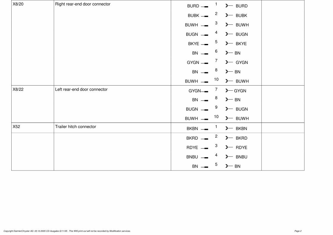
X8/20 Right rear-end door connector BURD�� 1�� BURD
BUBK�� 2�� BUBK
BUWH �� 3�� BUWH
BUGN �� 4�� BUGN
BKYE�� 5�� BKYE
BN �� 6��BN
GYGN�� 7�� GYGN
BN �� 8��BN
BUWH �� 10�� BUWH
X8/22 Left rear-end door connector GYGN� 7 � GYGN
BN �� 8��BN
BUGN �� 9�� BUGN
BUWH �� 10�� BUWH
X52 Trailer hitch connector BKBN �� 1�� BKBN
BKRD �� 2�� BKRD
RDYE �� 3�� RDYE
BNBU �� 4�� BNBU
BN �� 5��BN
Copyright DaimlerChrysler AG 03.12.2005 CD-Ausgabe G/11/05 . This WIS print-out will not be recorded by Modification services. Page 2

GF00.19-S-1000-24VB Location and assignment of line and plug Model 639connectors - underfloor
Shown on left side of vehicle
S54.18-4517-05
Copyright DaimlerChrysler AG 12/3/05 G/11/05. This WIS printout will not be recorded by the update service. Page 1

Illustrated on right side of vehicle
S35.00-4510-06
Code Designation NotesCable colors Cable colors
� �X62/8 1Rpm sensor and brake wear sensor connector, left rear BK GNRD
� �2WH GNBN
� �1WH BU
Copyright DaimlerChrysler AG 12/3/05 G/11/05. This WIS printout will not be recorded by the update service. Page 2

� �2BK BUBN
� �1WH YE
� �2BK YEBN
� �1BK green
� �2WH GNRD
� �X62/21 1ABS/ASR rpm signal connector, left rear WH YE
� �2BK YEBN
� �X62/22 1ABS/ASR rpm signal connector, right rear WH BU
� �2BK BUBN
� �X62/39 1BBV rear axle connector, left BK GN
� �2WH GNRD
� �X62/40 1BBV rear axle connector, right BK GNRD
� �2WH GNBN
Copyright DaimlerChrysler AG 12/3/05 G/11/05. This WIS printout will not be recorded by the update service. Page 3

GF00.19-S-1000-28VB Location and assignment of line and plug Model 639connectors - center console
Code Designation NotesCable colors Cable colors
� �X28/23 1Airbag connector, driver and front passenger VT VT
� �2GN GN
� �3BUGN BUGN
� �4BNBK BNBK
Copyright DaimlerChrysler AG 12/3/05 G/11/05. This WIS printout will not be recorded by the update service. Page 1

N01.00-2432-06
Code Designation NotesCable colors Cable colors
� �X15 1Engine fan 100 °C temperature switch connector RD RD
� �2BN BN
� �3BUVT BU
Copyright DaimlerChrysler AG 12/3/05 G/11/05. This WIS printout will not be recorded by the update service. Page 2

� �4BUWH BUWH
� �X62/6 1Rpm sensor and brake wear sensor connector, right WH WH
front
� �2BK WHYE
�1BK
�2WH
�3 YEVT
�4 VTGN
� �X62/7 1Rpm sensor and brake wear sensor connector, left front WH BK
� �2BK BKYE
�1BK
�2WH
�3 VTWH
�4 YEVT
Copyright DaimlerChrysler AG 12/3/05 G/11/05. This WIS printout will not be recorded by the update service. Page 3

06/05 Transporters • Electrics <>Van - Electrical Systems Wiring Diagrams VITO (Model 639)
Battery, starting charging circuit Chapter 5

PE15.00-S-2000VA Wiring diagram for starter, alternator 25.3.03
ENGINES 646.982 /983, 112.951 /976, 642.990 up to 28.2.05 in MODELS 639.601 /603 /605 /701 /703 /705 up to 28.2.05ENGINES 646.982, 112.951 /976, 642.990 up to 28.2.05 in MODELS 639.711 /713 /811 /813 /815 up to 28.2.05
PE15.00-S-2000-99VA Wiring diagram for starter, alternator PE15.00-S-2000-99VA
PE15.00-S-2000-60VA Legend of wiring diagram for starter, alternator PE15.00-S-2000-60VA
OV00.01-S-1901-03VA Use of wiring diagrams OV00.01-S-1901-03VA
OV00.01-S-1901VA Search aid for all wiring diagram groups OV00.01-S-1901VA
OV00.01-S-1909VA Search aid for all electrical components Components from A to E OV00.01-S-1909VA
OV00.01-S-1909VB Search aid for all electrical components Components from F to J OV00.01-S-1909VB
OV00.01-S-1909VC Search aid for all electrical components Components from K to O OV00.01-S-1909VC
OV00.01-S-1909VD Search aid for all electrical components Components from P to T OV00.01-S-1909VD
OV00.01-S-1909VE Search aid for all electrical components Components from U to Z OV00.01-S-1909VE
OV00.01-S-1001-27VA Abbreviations for wiring diagrams OV00.01-S-1001-27VA
OV00.01-S-1001-28VA Abbreviations of signal and circuit designations for wiring diagrams
OV00.01-S-1001-28VA
GF00.19-S-1000VB Location and assignment of line and plug connectors
GF00.19-S-1000VB
GF00.19-S-1100VB Location and assignment of connectors and sockets
GF00.19-S-1100VB
GF00.19-S-2000VB Location and assignment of ground points GF00.19-S-2000VB
GF00.19-S-3000VB Location and assignment of Z connector sleeves (line connectors in wiring harness)
GF00.19-S-3000VB
GF54.15-S-0900VA Fuse and relay box - location/assignment GF54.15-S-0900VA
Copyright DaimlerChrysler AG 03.12.2005 CD-Ausgabe G/11/05 . This WIS print-out will not be recorded by Modification services. Page 1

PE15.00-S-2000-60VA Legend of wiring diagram for starter, alternator ENGINES 646.982 /983, 112.951 /976, 642.990 up to 28.2.05 in MODELS 639.601 /603 /605/ 701 /703 /705 up to 28.2.05
ENGINES 646.982, 112.951 /976, 642.990 up to 28.2.05 in MODELS 639.711 /713 /811/ 813 /815 up to 28.2.05
Code Designation Coordinates
A0 Color code key 48L
F1 1-pin prefuse box 12G
F4 Fuse box (1-pin) 27L
F5 Fuse box (1-pin) 24L
F34 Fuse block, 22-pin 29K
F35 Fuse block, 22-pin 32L
G1 Battery 12K
G2/2 Alternator 40A
G2/5 200 A Alternator 4A
K40/9 Fuse and relay block 2K9K19K21K39K
M1 Starter 10A
N3/9 CDI control unit 5K
N14/2 Glow output stage 34K
N33/4 Heater booster control unit 16K
U53 Valid for automatic air conditioning "Thermotronic" 26H
U54 Valid for regulated air conditioning "Tempmatic" 26H
U1001 Valid for engine OM 646 with automatic transmission 1A
U1002 Valid for PTC element 16HCopyright DaimlerChrysler AG 03.12.2005 CD-Ausgabe G/11/05 . This WIS print-out will not be recorded by Modification services. Page 1
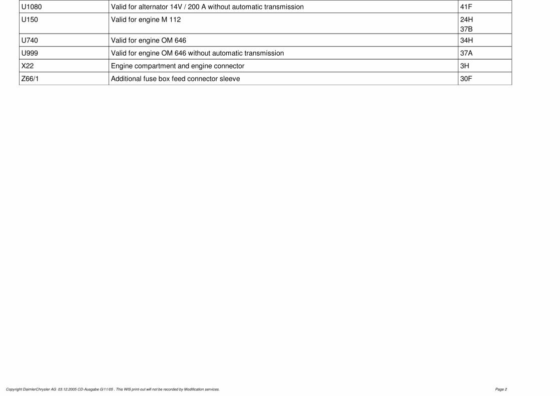
U1080 Valid for alternator 14V / 200 A without automatic transmission 41F
U150 Valid for engine M 112 24H37B
U740 Valid for engine OM 646 34H
U999 Valid for engine OM 646 without automatic transmission 37A
X22 Engine compartment and engine connector 3H
Z66/1 Additional fuse box feed connector sleeve 30F
Copyright DaimlerChrysler AG 03.12.2005 CD-Ausgabe G/11/05 . This WIS print-out will not be recorded by Modification services. Page 2

Copyright DaimlerChrysler AG 03.12.2005 CD-Ausgabe G/11/05 . This WIS print-out will not be recorded by Modification services. Page 1

Copyright DaimlerChrysler AG 03.12.2005 CD-Ausgabe G/11/05 . This WIS print-out will not be recorded by Modification services. Page 2

Copyright DaimlerChrysler AG 03.12.2005 CD-Ausgabe G/11/05 . This WIS print-out will not be recorded by Modification services. Page 3

PE15.00-S-2000VB Wiring diagram for starter, alternator 24.8.05
ENGINES 646.982 /983, 112.951 /976, 642.990 as of 1.3.05 in MODELS 639.601 /603 /605 /701 /703 /705 as of 1.3.05ENGINES 646.982, 112.951 /976, 642.990 as of 1.3.05 in MODELS 639.711 /713 /811 /813 /815 as of 1.3.05
PE15.00-S-2000-99VB Wiring diagram for starter, alternator PE15.00-S-2000-99VB
PE15.00-S-2000-60VB Legend of wiring diagram for starter, alternator PE15.00-S-2000-60VB
OV00.01-S-1901-03VA Use of wiring diagrams OV00.01-S-1901-03VA
OV00.01-S-1901VA Search aid for all wiring diagram groups OV00.01-S-1901VA
OV00.01-S-1909VA Search aid for all electrical components Components from A to E OV00.01-S-1909VA
OV00.01-S-1909VB Search aid for all electrical components Components from F to J OV00.01-S-1909VB
OV00.01-S-1909VC Search aid for all electrical components Components from K to O OV00.01-S-1909VC
OV00.01-S-1909VD Search aid for all electrical components Components from P to T OV00.01-S-1909VD
OV00.01-S-1909VE Search aid for all electrical components Components from U to Z OV00.01-S-1909VE
OV00.01-S-1001-27VA Abbreviations for wiring diagrams OV00.01-S-1001-27VA
OV00.01-S-1001-28VA Abbreviations of signal and circuit designations for wiring diagrams
OV00.01-S-1001-28VA
GF00.19-S-1000VB Location and assignment of line and plug connectors
GF00.19-S-1000VB
GF00.19-S-1100VB Location and assignment of connectors and sockets
GF00.19-S-1100VB
GF00.19-S-2000VB Location and assignment of ground points GF00.19-S-2000VB
GF00.19-S-3000VB Location and assignment of Z connector sleeves (line connectors in wiring harness)
GF00.19-S-3000VB
GF54.15-S-0900VA Fuse and relay box - location/assignment GF54.15-S-0900VA
Copyright DaimlerChrysler AG 03.12.2005 CD-Ausgabe G/11/05 . This WIS print-out will not be recorded by Modification services. Page 1

PE15.00-S-2000-60VB Legend of wiring diagram for starter, alternator ENGINES 646.982 /983, 112.951 /976, 642.990 from 1.3.05 in MODELS 639.601 /603 /605/ 701 /703 /705 from 1.3.05
ENGINES 646.982, 112.951 /976, 642.990 from 1.3.05 in MODELS 639.711 /713 /811/ 813 /815 from 1.3.05
Code Designation Coordinates
A0 Color code key 64L
F1 1-pin prefuse box 31G
F4 Fuse box (1-pin) 53K
F5 Fuse box (1-pin) 50K
F34 Fuse block, 22-pin 42K
F35 Fuse block, 22-pin 44K
G1 Battery 35K
G2/2 Alternator 24B
G2/5 200 A Alternator 17B
G2/6 Alternator 200 A with LIN bus 4B
K40/9 Fuse and relay block 8K15K22K29K37K40K
M1 Starter 29A
N3/9 CDI control unit 18K
N3/20 CDI control unit 3L
N14/2 Glow output stage 58K
N14/3 Glow output stage 11L55K
Copyright DaimlerChrysler AG 03.12.2005 CD-Ausgabe G/11/05 . This WIS print-out will not be recorded by Modification services. Page 1

N33/4 Heater booster control unit 47L
U53 Valid for automatic air conditioning "Thermotronic" 52H
U54 Valid for regulated air conditioning "Tempmatic" 52H
U1001 Valid for engine OM 646 with automatic transmission 15B
U1002 Valid for PTC element 47H
U1080 Valid for alternator 14V / 200 A without automatic transmission 23G
U150 Valid for engine M 112 21B50H
U740 Valid for engine OM 646 58H
U960 Valid for engine OM 642 1B55H
U999 Valid for engine OM 646 without automatic transmission 21B
X22 Engine compartment and engine connector 16H
Z66/1 Additional fuse box feed connector sleeve 43G
Z203/3 Alternator connector sleeve 3H
Copyright DaimlerChrysler AG 03.12.2005 CD-Ausgabe G/11/05 . This WIS print-out will not be recorded by Modification services. Page 2

Copyright DaimlerChrysler AG 03.12.2005 CD-Ausgabe G/11/05 . This WIS print-out will not be recorded by Modification services. Page 1

Copyright DaimlerChrysler AG 03.12.2005 CD-Ausgabe G/11/05 . This WIS print-out will not be recorded by Modification services. Page 2

Copyright DaimlerChrysler AG 03.12.2005 CD-Ausgabe G/11/05 . This WIS print-out will not be recorded by Modification services. Page 3

Copyright DaimlerChrysler AG 03.12.2005 CD-Ausgabe G/11/05 . This WIS print-out will not be recorded by Modification services. Page 4

06/05 Transporters • Electrics <>Van - Electrical Systems Wiring Diagrams VITO (Model 639)
Voltage supply fuses Chapter 6

PE54.15-S-2005VA Wiring diagram of voltage supply of fuses 25.3.03
MODEL 639.601 /603 /605 /701 /703 /705 /711 /713 /811 /813 /815left seat frame
PE54.15-S-2005-99VA Wiring diagram of voltage supply of fuses PE54.15-S-2005-99VA
PE54.15-S-2005-60VA Legend of wiring diagram for voltage supply of fuses
PE54.15-S-2005-60VA
OV00.01-S-1901-03VA Use of wiring diagrams OV00.01-S-1901-03VA
OV00.01-S-1901VA Search aid for all wiring diagram groups OV00.01-S-1901VA
OV00.01-S-1909VA Search aid for all electrical components Components from A to E OV00.01-S-1909VA
OV00.01-S-1909VB Search aid for all electrical components Components from F to J OV00.01-S-1909VB
OV00.01-S-1909VC Search aid for all electrical components Components from K to O OV00.01-S-1909VC
OV00.01-S-1909VD Search aid for all electrical components Components from P to T OV00.01-S-1909VD
OV00.01-S-1909VE Search aid for all electrical components Components from U to Z OV00.01-S-1909VE
OV00.01-S-1001-27VA Abbreviations for wiring diagrams OV00.01-S-1001-27VA
OV00.01-S-1001-28VA Abbreviations of signal and circuit designations for wiring diagrams
OV00.01-S-1001-28VA
GF00.19-S-1000VB Location and assignment of line and plug connectors
GF00.19-S-1000VB
GF00.19-S-1100VB Location and assignment of connectors and sockets
GF00.19-S-1100VB
GF00.19-S-2000VB Location and assignment of ground points GF00.19-S-2000VB
GF00.19-S-3000VB Location and assignment of Z connector sleeves (line connectors in wiring harness)
GF00.19-S-3000VB
GF54.15-S-0900VA Fuse and relay box, location/assignment GF54.15-S-0900VA
Copyright DaimlerChrysler AG 03.12.2005 CD-Ausgabe G/11/05 . This WIS print-out will not be recorded by Modification services. Page 1

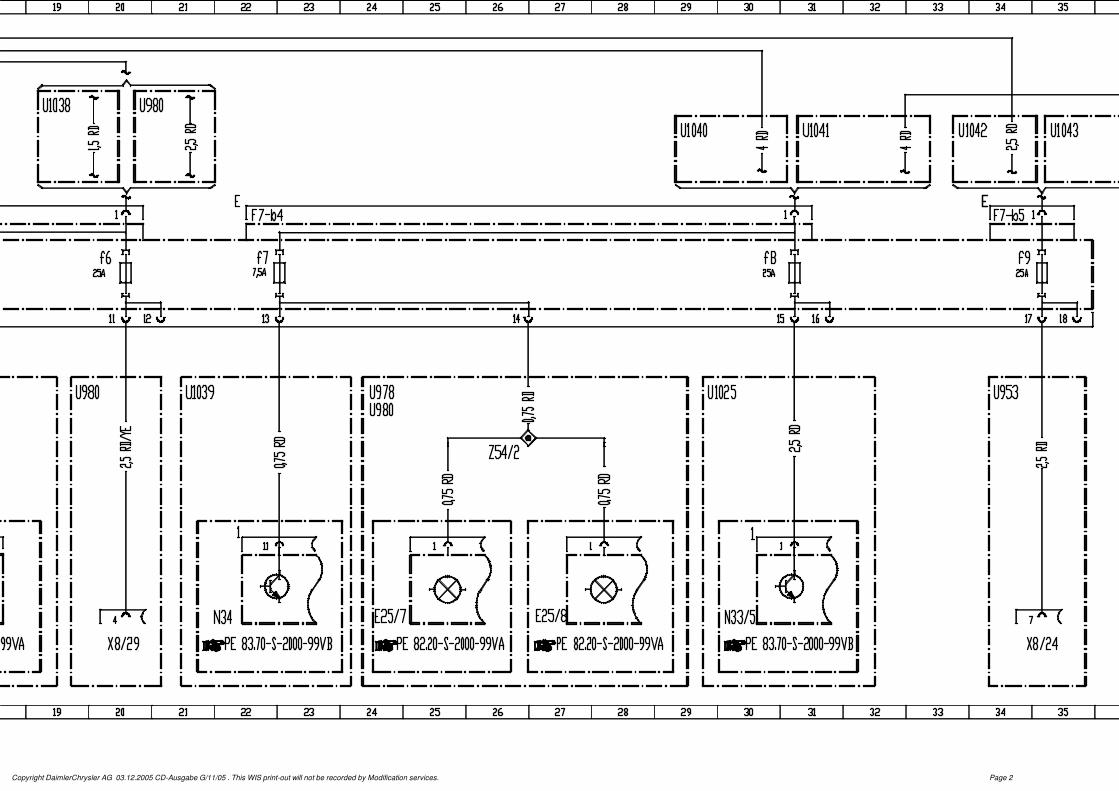
PE54.15-S-2005-60VA Legend of wiring diagram for voltage supply of fuses
MODEL 639.601 /603 /605 /701 /703 /705 /711 /713 /811 /813 /815left seat frame
Code Designation Coordinates
E25/7 Transistor lamp, left 24K
E25/8 Transistor lamp, right 27K
F6 Fuse box (1-pin) 3E
F7 Fuse block (9-pin) 6E
F7-b1 Fuse connector (2-pin) 7D
F7-b2 Fuse connector (2-pin) 12D
F7-b3 Fuse connector (2-pin) 17D
F7-b4 Fuse connector (2-pin) 22D
F7-b5 Fuse connector (1-pin) 34D
F7f1 Left door control unit fuse 7D
F7f2 Right door control unit fuse 9D
F7f3 Fuse 1 (PSM) 12D
F7f4 Fuse 2 (PSM) 14D
F7f5 12V socket fuse, front passenger seat box 17D
F7f6 Charge line to vehicle battery fuse 20D
F7f7 Timer and illumination power supply fuse 22D
F7f8 STH power supply fuse 30D
F7f9 Pop-up roof power supply fuse 34D
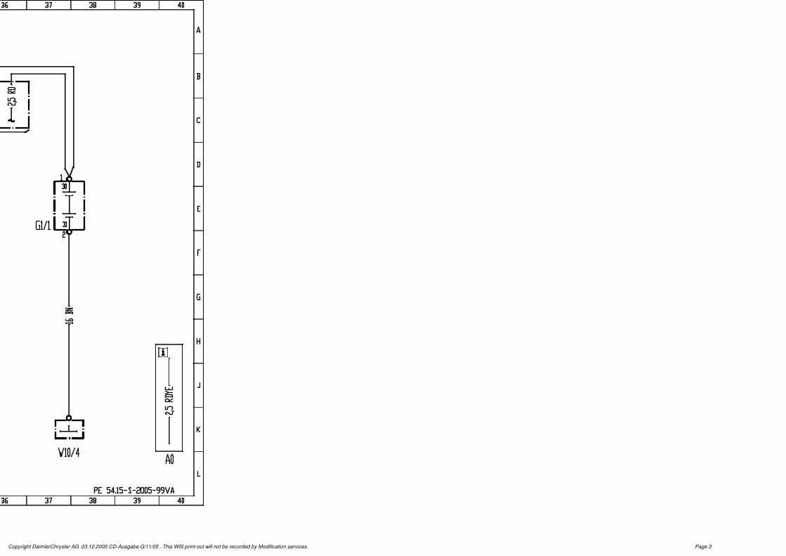
G1 Battery 1E
G1/1 Additional battery 37E
K40/9 Fuse and relay block 3K
N26/15 PSM control unit 12K
N33/5 Hot air stationary heater control unit 30K
Copyright DaimlerChrysler AG 03.12.2005 CD-Ausgabe G/11/05 . This WIS print-out will not be recorded by Modification services. Page 1

N34 STH timer 22K
N69/1 Door control unit, left front 6K
N69/2 Door control unit, right front 9K
U26 Valid for taxi version with emergency alarm system 11G
U27 Valid for taxi version without emergency alarm system 11G
U1025 Valid for warm air auxiliary heater with timer and temperature control 29G
U1036 Valid for freezer vehicle 11H
U1037 Valid for refrigerator vehicle 11H
U1038 Valid for FUN equipment line with refrigerator box 16G19B
U1039 Valid for warm air auxiliary heater with timer and temperature control with FUN equipment line or comfort plus package
21G
U1040 Valid for FUN equipment line or comfort plus package without additional heavy-duty battery 29B
U1041 Valid for FUN equipment line or comfort plus package with heavy-duty battery in addition or for "Marco Polo" camper
31B
U1042 Valid for electrohydraulic "Easy up" pop-up roof without heavy-duty battery in addition 33B
U1043 Valid for electrohydraulic "Easy up" pop-up roof with heavy-duty battery in addition or gel additional battery 12V 80Ah
35B
U914 Valid for rental vehicle package with emergency alarm system 11H
U934 Valid for rental vehicle package without emergency alarm system 11J
U947 Valid for parameterizable special module 11G14C
U953 Valid for electrohydraulic "Easy up" pop-up roof 11G34G
U978 Valid for FUN equipment line 24G
U980 Valid for "Marco Polo" camper 19G20B24G
W10 Ground (battery) 2L
W10/4 Ground (additional battery) 37L
X8/24 Pop-up roof connector (Westfalia) 34L
X8/29 Separation point 2 (Westfalia) 20L
X58/17 12V socket 16KCopyright DaimlerChrysler AG 03.12.2005 CD-Ausgabe G/11/05 . This WIS print-out will not be recorded by Modification services. Page 2

Copyright DaimlerChrysler AG 03.12.2005 CD-Ausgabe G/11/05 . This WIS print-out will not be recorded by Modification services. Page 1
Copyright DaimlerChrysler AG 03.12.2005 CD-Ausgabe G/11/05 . This WIS print-out will not be recorded by Modification services. Page 2
Copyright DaimlerChrysler AG 03.12.2005 CD-Ausgabe G/11/05 . This WIS print-out will not be recorded by Modification services. Page 3

PE54.15-S-2005VB Wiring diagram of voltage supply of fuses 25.7.03
MODEL 639.601 /603 /605 /701 /703 /705 /711 /713 /811 /813 /815Sheet 1, E-box F34
PE54.15-S-2005-99VB Wiring diagram of voltage supply of fuses Sheet 1 PE54.15-S-2005-99VB
PE54.15-S-2005-60VB Legend of wiring diagram for voltage supply of fuses
Sheet 1 PE54.15-S-2005-60VB
OV00.01-S-1901-03VA Use of wiring diagrams OV00.01-S-1901-03VA
OV00.01-S-1901VA Search aid for all wiring diagram groups OV00.01-S-1901VA
OV00.01-S-1909VA Search aid for all electrical components Components from A to E OV00.01-S-1909VA
OV00.01-S-1909VB Search aid for all electrical components Components from F to J OV00.01-S-1909VB
OV00.01-S-1909VC Search aid for all electrical components Components from K to O OV00.01-S-1909VC
OV00.01-S-1909VD Search aid for all electrical components Components from P to T OV00.01-S-1909VD
OV00.01-S-1909VE Search aid for all electrical components Components from U to Z OV00.01-S-1909VE
OV00.01-S-1001-27VA Abbreviations for wiring diagrams OV00.01-S-1001-27VA
OV00.01-S-1001-28VA Abbreviations of signal and circuit designations for wiring diagrams
OV00.01-S-1001-28VA
GF00.19-S-1000VB Location and assignment of line and plug connectors
GF00.19-S-1000VB
GF00.19-S-1100VB Location and assignment of connectors and sockets
GF00.19-S-1100VB
GF00.19-S-2000VB Location and assignment of ground points GF00.19-S-2000VB
GF00.19-S-3000VB Location and assignment of Z connector sleeves (line connectors in wiring harness)
GF00.19-S-3000VB
GF54.15-S-0900VA Fuse and relay box, location/assignment GF54.15-S-0900VA
Copyright DaimlerChrysler AG 03.12.2005 CD-Ausgabe G/11/05 . This WIS print-out will not be recorded by Modification services. Page 1

PE54.15-S-2005-60VB Legend of wiring diagram for voltage supply of fuses
MODEL 639.601 /603 /605 /701 /703 /705 /711 /713 /811 /813 /815Sheet 1, E-box F34
Code Designation Coordinates
A49/4 STH radio receiver 69K
E15 Dome lamp with reading lamp, front 54K
E15/3 Dome lamp, front of rear 50K
E15/4 Dome lamp, rear of rear 48K
E15/6 Interior lamp, left front grab handle 37K
E15/7 Interior lamp, right front grab handle 39K
E15/8 Interior lamp, left rear grab handle 42K
E15/9 Interior lamp, right rear grab handle 45K
E15/29 Load compartment lamp 1, right 20K30K
E15/30 Load compartment lamp 2, left 23K33K
E18/1 Trunk lamp 17K27K
F34 Fuse block, 22-pin 6C
F34f21 Exterior lamp switch fuse 7B
F34f22 TV console fuse 11B
F34f23 Interior lamps fuse 37B
F34f24 SHD overhead control panel fuse 58B
F34f25 Rear sliding roof fuse 64B
F34f26 STH radio receiver fuse 69B
F34f27 Front climate control fuse 73B
F34f28 Socket fuse, TV console 76B
Copyright DaimlerChrysler AG 03.12.2005 CD-Ausgabe G/11/05 . This WIS print-out will not be recorded by Modification services. Page 1
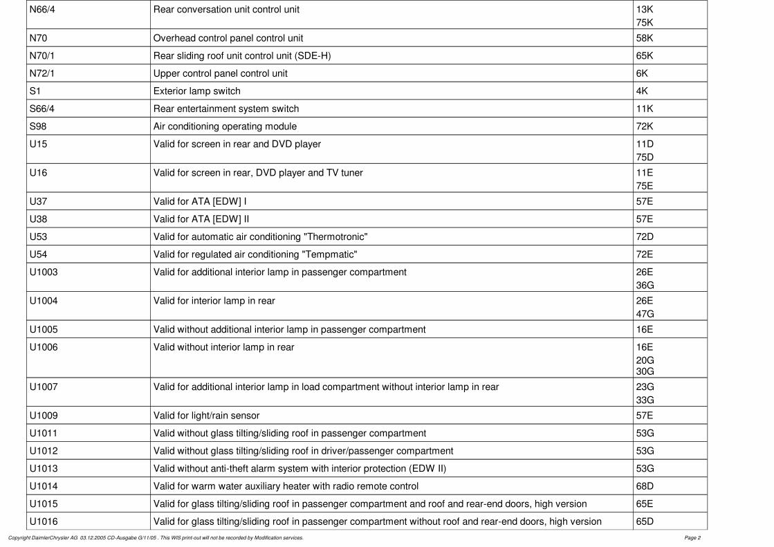
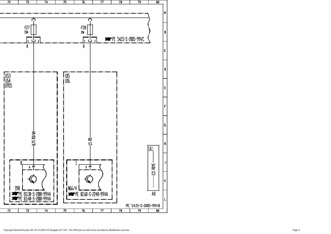
N66/4 Rear conversation unit control unit 13K75K
N70 Overhead control panel control unit 58K
N70/1 Rear sliding roof unit control unit (SDE-H) 65K
N72/1 Upper control panel control unit 6K
S1 Exterior lamp switch 4K
S66/4 Rear entertainment system switch 11K
S98 Air conditioning operating module 72K
U15 Valid for screen in rear and DVD player 11D75D
U16 Valid for screen in rear, DVD player and TV tuner 11E75E
U37 Valid for ATA [EDW] I 57E
U38 Valid for ATA [EDW] II 57E
U53 Valid for automatic air conditioning "Thermotronic" 72D
U54 Valid for regulated air conditioning "Tempmatic" 72E
U1003 Valid for additional interior lamp in passenger compartment 26E36G
U1004 Valid for interior lamp in rear 26E47G
U1005 Valid without additional interior lamp in passenger compartment 16E
U1006 Valid without interior lamp in rear 16E20G30G
U1007 Valid for additional interior lamp in load compartment without interior lamp in rear 23G33G
U1009 Valid for light/rain sensor 57E
U1011 Valid without glass tilting/sliding roof in passenger compartment 53G
U1012 Valid without glass tilting/sliding roof in driver/passenger compartment 53G
U1013 Valid without anti-theft alarm system with interior protection (EDW II) 53G
U1014 Valid for warm water auxiliary heater with radio remote control 68D
U1015 Valid for glass tilting/sliding roof in passenger compartment and roof and rear-end doors, high version 65E
U1016 Valid for glass tilting/sliding roof in passenger compartment without roof and rear-end doors, high version 65DCopyright DaimlerChrysler AG 03.12.2005 CD-Ausgabe G/11/05 . This WIS print-out will not be recorded by Modification services. Page 2

U1017 Valid for electrohydraulic "Easy up" pop-up roof and glass sliding/lifting roof in driver area/front passenger area 62D
U1018 Valid without EDW I 53H
U1019 Valid without light/rain sensor 53H
U1024 Valid for DBE with 2 reading spotlights or garage door opener without glass tilting/sliding roof in driver/passenger compartment, glass tilting/sliding roof in passenger compartment, light/rain sensor, EDW II or EDW I
59D
U949 Valid for glass tilting/sliding roof in passenger compartment 57E
U954 Valid for glass tilting/sliding roof in driver/passenger compartment 57D
U955 Valid for alternator 14V / 200 Ah 72E
U978 Valid for FUN equipment line 17G27G36G
U980 Valid for "Marco Polo" camper 17H27H36G
U982 Valid for MPV 17G27G
U983 Valid for TREND equipment line 17G27G
U984 Valid for AMBIENTE equipment line 17H27H
U987 Valid without DBE with 2 reading spotlights 53H
W29/9 Ground (right D-pillar) 62L
X8/25 Sliding roof in pop-up roof separation point (Westfalia) 63L
X18/2 Load compartment lamp connector 21F30F
Z4/1 Ceiling illumination terminal 30 connector sleeve 41G49G54G
Z66/1 Additional fuse box feed connector sleeve 1G
Copyright DaimlerChrysler AG 03.12.2005 CD-Ausgabe G/11/05 . This WIS print-out will not be recorded by Modification services. Page 3

Copyright DaimlerChrysler AG 03.12.2005 CD-Ausgabe G/11/05 . This WIS print-out will not be recorded by Modification services. Page 1

Copyright DaimlerChrysler AG 03.12.2005 CD-Ausgabe G/11/05 . This WIS print-out will not be recorded by Modification services. Page 2

Copyright DaimlerChrysler AG 03.12.2005 CD-Ausgabe G/11/05 . This WIS print-out will not be recorded by Modification services. Page 3

Copyright DaimlerChrysler AG 03.12.2005 CD-Ausgabe G/11/05 . This WIS print-out will not be recorded by Modification services. Page 4
Copyright DaimlerChrysler AG 03.12.2005 CD-Ausgabe G/11/05 . This WIS print-out will not be recorded by Modification services. Page 5
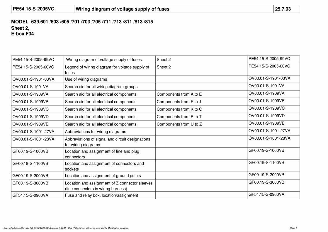
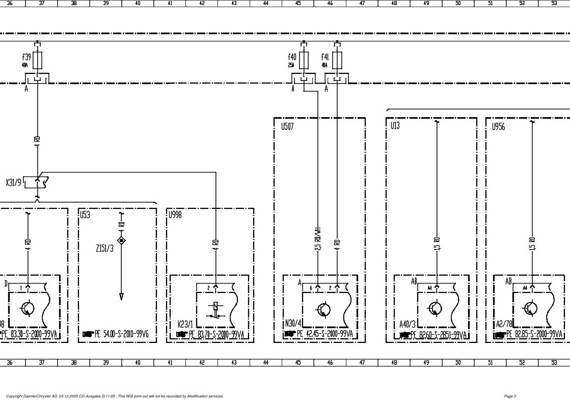
PE54.15-S-2005VC Wiring diagram of voltage supply of fuses 25.7.03
MODEL 639.601 /603 /605 /701 /703 /705 /711 /713 /811 /813 /815Sheet 2, E-box F34
PE54.15-S-2005-99VC Wiring diagram of voltage supply of fuses Sheet 2 PE54.15-S-2005-99VC
PE54.15-S-2005-60VC Legend of wiring diagram for voltage supply of fuses
Sheet 2 PE54.15-S-2005-60VC
OV00.01-S-1901-03VA Use of wiring diagrams OV00.01-S-1901-03VA
OV00.01-S-1901VA Search aid for all wiring diagram groups OV00.01-S-1901VA
OV00.01-S-1909VA Search aid for all electrical components Components from A to E OV00.01-S-1909VA
OV00.01-S-1909VB Search aid for all electrical components Components from F to J OV00.01-S-1909VB
OV00.01-S-1909VC Search aid for all electrical components Components from K to O OV00.01-S-1909VC
OV00.01-S-1909VD Search aid for all electrical components Components from P to T OV00.01-S-1909VD
OV00.01-S-1909VE Search aid for all electrical components Components from U to Z OV00.01-S-1909VE
OV00.01-S-1001-27VA Abbreviations for wiring diagrams OV00.01-S-1001-27VA
OV00.01-S-1001-28VA Abbreviations of signal and circuit designations for wiring diagrams
OV00.01-S-1001-28VA
GF00.19-S-1000VB Location and assignment of line and plug connectors
GF00.19-S-1000VB
GF00.19-S-1100VB Location and assignment of connectors and sockets
GF00.19-S-1100VB
GF00.19-S-2000VB Location and assignment of ground points GF00.19-S-2000VB
GF00.19-S-3000VB Location and assignment of Z connector sleeves (line connectors in wiring harness)
GF00.19-S-3000VB
GF54.15-S-0900VA Fuse and relay box, location/assignment GF54.15-S-0900VA
Copyright DaimlerChrysler AG 03.12.2005 CD-Ausgabe G/11/05 . This WIS print-out will not be recorded by Modification services. Page 1

PE54.15-S-2005-60VC Legend of wiring diagram for voltage supply of fuses
MODEL 639.601 /603 /605 /701 /703 /705 /711 /713 /811 /813 /815Sheet 2, E-box F34
Code Designation Coordinates
A0 Color code key 72L
A2 Radio / Sound 10 / Sound 40 / Audio 10 58K61K64K
A2/56 Radio and navigation unit 54K
A2/78 Audio-Video-Navigation (AVN) 51K
A35/11 SBS control unit 4L
A35/13 Telephone transmitter/receiver, D2B 7L
A40/3 COMAND operating, display and control unit 48L
A56 Modular tachograph 17K
F34 Fuse block, 22-pin 7C
F34f29 D2BPortable CTEL fuse, portable CTEL and SBS 8B
F34f30 Heated seats fuse 14B
F34f31 Fuse, tachograph 18B
F34f32 Fuse 32 20B
F34f33 Data link connector fuse 23B
F34f34 Fuse 34 24B
F34f35 Air conditioning pulsed valve power supply fuse 26B
F34f36 SRA fuse 27B
F34f37 ATA [EDW] siren fuse 30B
F34f38 EIS [EZS] steering lock fuse 33B
F34f39 Front blower fuse 36B
F34f40 Brake system valve fuse 45B
Copyright DaimlerChrysler AG 03.12.2005 CD-Ausgabe G/11/05 . This WIS print-out will not be recorded by Modification services. Page 1

F34f41 Brake system delivery pump fuse 46B
F34f42 Radio fuse or DIN navigation 57B
H3/1 Alarm signal horn with additional battery 30K
K2 Headlamp cleaning system relay 27K
K23/1 Blower motor relay 41L
N30/4 ESP control unit 45K
N72/1 Upper control panel control unit 14K
N73 EIS [EZS] control unit 33K
N123 Hands-free system control unit 10L
S98 Air conditioning operating module 36L
U10 Valid for Sound 40 Pro radio 64D
U11 Valid for radio with cassette drive, Latin America 61E
U13 Valid for auto pilot system with TMC interface 48D
U38 Valid for ATA [EDW] II 30D
U51 Valid for telephone preinstallation 10D
U52 Valid for voice control 4D
U53 Valid for automatic air conditioning "Thermotronic" 38G
U55 Not valid for air conditioning 35G
U285 Valid for partially electric seat adjustment, driver 14E
U286 Valid for partially electric seat adjustment, front passenger 14E
U507 Valid for Electronic Stability Program (ESP) 45D
U909 Valid for radio preinstallation 67D
U910 Valid for radio Sound 10 with cassette drive 57D
U913 Valid for networked telephone preinstallation 7D
U922 Valid for heater for front passenger seat 14D
U923 Valid for heater for driver seat 14D
U928 Valid for headlamp cleaning system 27D
U956 Valid for auto pilot system for Japan, large display 51D
U957 Valid for Audio 10 radio with cassette drive 61D
U958 Valid for Audio 10 radio with CD 61ECopyright DaimlerChrysler AG 03.12.2005 CD-Ausgabe G/11/05 . This WIS print-out will not be recorded by Modification services. Page 2

U959 Valid for Audio 30 APS radio with TMC interface 54D
U968 Valid for 1 day/2 driver tachograph 17D
U998 Valid for auxiliary heater without air conditioning system 41G
W12 Ground (cockpit and center console) 20L
X31/9 Blower switch feed-in connector 36F
Z66/1 Additional fuse box feed connector sleeve 2G
Z151/3 A/C 1st stage connector sleeve 39H
Copyright DaimlerChrysler AG 03.12.2005 CD-Ausgabe G/11/05 . This WIS print-out will not be recorded by Modification services. Page 3

Copyright DaimlerChrysler AG 03.12.2005 CD-Ausgabe G/11/05 . This WIS print-out will not be recorded by Modification services. Page 1

Copyright DaimlerChrysler AG 03.12.2005 CD-Ausgabe G/11/05 . This WIS print-out will not be recorded by Modification services. Page 2
Copyright DaimlerChrysler AG 03.12.2005 CD-Ausgabe G/11/05 . This WIS print-out will not be recorded by Modification services. Page 3

Copyright DaimlerChrysler AG 03.12.2005 CD-Ausgabe G/11/05 . This WIS print-out will not be recorded by Modification services. Page 4
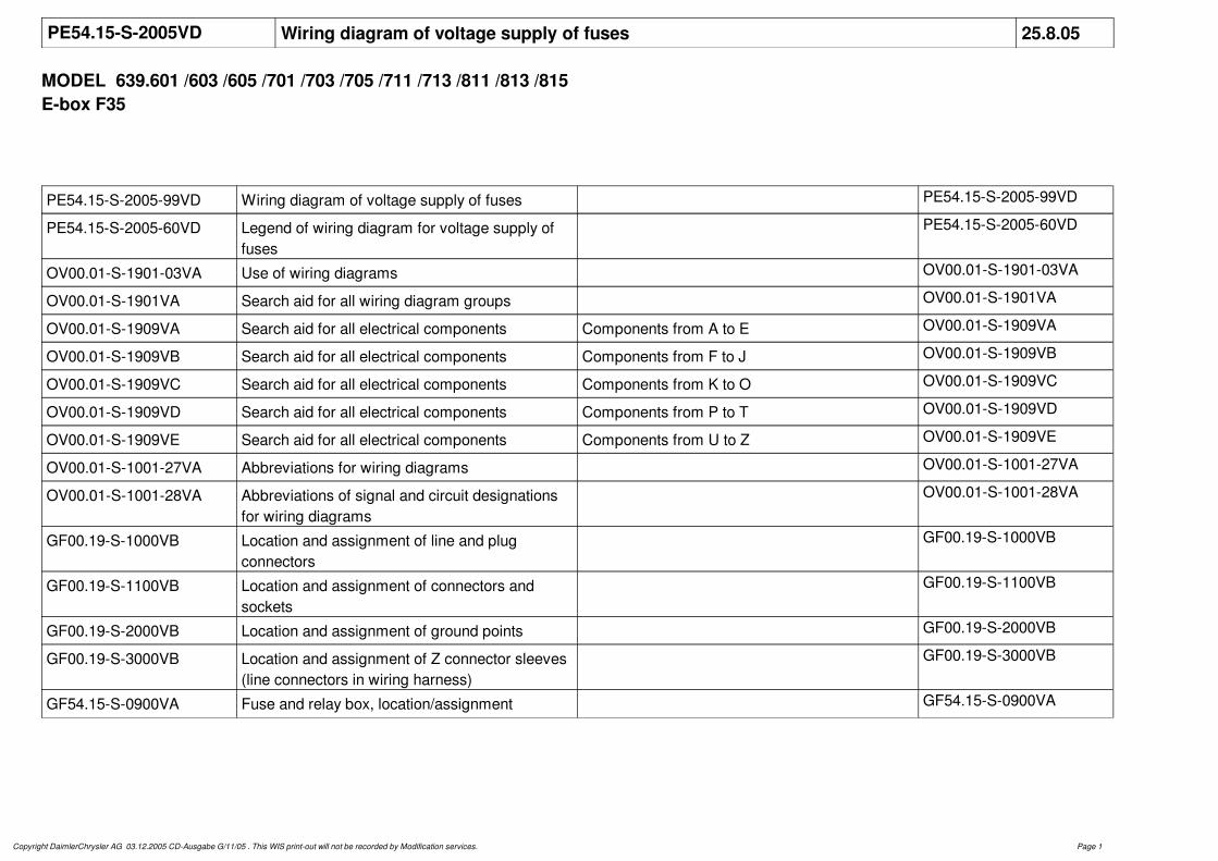
PE54.15-S-2005VD Wiring diagram of voltage supply of fuses 25.8.05
MODEL 639.601 /603 /605 /701 /703 /705 /711 /713 /811 /813 /815E-box F35
PE54.15-S-2005-99VD Wiring diagram of voltage supply of fuses PE54.15-S-2005-99VD
PE54.15-S-2005-60VD Legend of wiring diagram for voltage supply of fuses
PE54.15-S-2005-60VD
OV00.01-S-1901-03VA Use of wiring diagrams OV00.01-S-1901-03VA
OV00.01-S-1901VA Search aid for all wiring diagram groups OV00.01-S-1901VA
OV00.01-S-1909VA Search aid for all electrical components Components from A to E OV00.01-S-1909VA
OV00.01-S-1909VB Search aid for all electrical components Components from F to J OV00.01-S-1909VB
OV00.01-S-1909VC Search aid for all electrical components Components from K to O OV00.01-S-1909VC
OV00.01-S-1909VD Search aid for all electrical components Components from P to T OV00.01-S-1909VD
OV00.01-S-1909VE Search aid for all electrical components Components from U to Z OV00.01-S-1909VE
OV00.01-S-1001-27VA Abbreviations for wiring diagrams OV00.01-S-1001-27VA
OV00.01-S-1001-28VA Abbreviations of signal and circuit designations for wiring diagrams
OV00.01-S-1001-28VA
GF00.19-S-1000VB Location and assignment of line and plug connectors
GF00.19-S-1000VB
GF00.19-S-1100VB Location and assignment of connectors and sockets
GF00.19-S-1100VB
GF00.19-S-2000VB Location and assignment of ground points GF00.19-S-2000VB
GF00.19-S-3000VB Location and assignment of Z connector sleeves (line connectors in wiring harness)
GF00.19-S-3000VB
GF54.15-S-0900VA Fuse and relay box, location/assignment GF54.15-S-0900VA
Copyright DaimlerChrysler AG 03.12.2005 CD-Ausgabe G/11/05 . This WIS print-out will not be recorded by Modification services. Page 1

PE54.15-S-2005-60VD Legend of wiring diagram for voltage supply of fuses
MODEL 639.601 /603 /605 /701 /703 /705 /711 /713 /811 /813 /815E-box F35
Code Designation Coordinates
A2/17 Antenna amplifier voltage supply 58K
A2/77 Telephone and communication unit 50K
A6n1 STH control unit 63K
A32/1 Rear air recirculation heater 35K
A32/2 Rear automatic air conditioning air unit 38K
F35 Fuse block, 22-pin 5B
F35f21 Left passenger compartment 12V socket fuse 7B
F35f22 Right passenger compartment 12V socket fuse 10B
F35f23 Trailer socket fuse 16B
F35f24 AAG fuse 23B
F35f25 Driver seat adjustment fuse 27B
F35f26 Front passenger seat adjustment fuse 31B
F35f27 Left electric sliding door fuse 33B
F35f28 Right electric sliding door fuse 35B
F35f29 Rear blower fuse 37B
F35f30 Air suspension or all-wheel drive fuse 42B
F35f31 PTS fuse 46B
F35f32 Tire pressure monitoring system fuse 49B
F35f33 Communications unit (Japan) or telephone (USA) fuse 51B
F35f34 Compensator fuse, VICS and TV amplifier (Japan) 58B
F35f35 STH control unit fuse 63B
F35f36 Tailgate power closing fuse 67B
F35f37 Rear air conditioning fuse 68B
Copyright DaimlerChrysler AG 03.12.2005 CD-Ausgabe G/11/05 . This WIS print-out will not be recorded by Modification services. Page 1

F35f38 Brake controller fuse (NAFTA) 70B
F35f39 Front blower fuse 71B
F35f40 Rear 12V socket fuse 73B
F35f41 Additional turn signal module fuse 76B
F35f42 Fuse 42 78B
N9/1 Additional turn signal module control unit 76K
N19/3 Rear AC control unit FONDKLA 66K
N28/1 Trailer connection unit [AAG] control unit 18K22K
N32/1 Left front seat adjustment control unit with memory 26K
N32/2 Right front seat adjustment control unit with memory 31K
N51/3 ENR control unit 42K
N62 PTS control unit 45K
N125 Telephone high frequency compensator 55K
S81/1 Rear automatic air conditioning operating switch 69K
U1026 Valid for ashtray and beverage holder in passenger compartment 2H6D
U1027 Valid for additional heat exchanger in passenger load compartment 2F34D35G69D
U1028 Valid for socket 12V in passenger compartment 2E72D
U1107 Valid up to08/2005 15D22D
U1108 Valid as of09/2005 18D
U285 Valid for partially electric seat adjustment, driver 2G26D
U286 Valid for partially electric seat adjustment, front passenger 2G30D
U538 Valid for Parktronic System 2F45D
U913 Valid for networked telephone preinstallation 2E54D
Copyright DaimlerChrysler AG 03.12.2005 CD-Ausgabe G/11/05 . This WIS print-out will not be recorded by Modification services. Page 2

U939 Valid for socket for rear-mounted bicycle carrier repeater lamps 2E15E15G18D22D
U940 Valid for electrical system for trailer socket 2D15E18E22E
U941 Valid for fixed trailer hitch 2H15E15G18E22E
U942 Valid for removable trailer hitch 2H15E15H18E22E
U945 Valid for warm water auxiliary heater 2F63D
U946 Valid for diesel heater booster 63D
U951 Valid for raisable/lowerable rear air suspension 2D41D
U952 Valid for Tempmatic/Additional air conditioning in rear 2G34D38G66D
U956 Valid for auto pilot system for Japan, large display 50D58D
U976 Valid for additional turn signal lamps on rear of roof 2G75D
X2/18 Antenna amplifier voltage supply connector 51F
X52 Trailer hitch connector 15F
X58 Trailer hitch socket (13-pin) 15K
X58/4 Load compartment socket, left front 7K
X58/12 Load compartment socket, right rear 72K
X58/15 Load compartment socket, right front 10K
Copyright DaimlerChrysler AG 03.12.2005 CD-Ausgabe G/11/05 . This WIS print-out will not be recorded by Modification services. Page 3

X96/4 Rear recirculation unit connector 2 37F
X137/1 VICS+ETC voltage supply separation point 61L
Z51 ELC [ENR] terminal 30 connector sleeve 42G
Z66/1 Additional fuse box feed connector sleeve 3G
Copyright DaimlerChrysler AG 03.12.2005 CD-Ausgabe G/11/05 . This WIS print-out will not be recorded by Modification services. Page 4

Copyright DaimlerChrysler AG 03.12.2005 CD-Ausgabe G/11/05 . This WIS print-out will not be recorded by Modification services. Page 1