x200-man
52
OPERATING MANUAL X200 COMPACT INTEGRATED DC POWER SYSTEM WWW.UNIPOWERCO.COM Manual No. X200M-5a © 2013 UNIPOWER LLC 05/13 x200-man All Rights Reserved NORTH AMERICA • 3900 Coral Ridge Drive, Coral Springs, Florida 33065, USA • Tel: +1 954-346-2442 • Fax: +1 954-340-7901 • Sales-[email protected] EUROPE • Parkland Business Centre, Chartwell Road, Lancing BN15 8UE, ENGLAND • Tel: +44(0)1903 768200 • Fax: +44(0)1903 764540 • Sales-[email protected]
-
Upload
alberto-perez -
Category
Documents
-
view
11 -
download
0
description
manual Gravitas
Transcript of x200-man

OPERATING MANUAL X200 COMPACT INTEGRATED
DC POWER SYSTEM
WWW.UNIPOWERCO.COM
Manual No. X200M-5a © 2013 UNIPOWER LLC 05/13 x200-man All Rights Reserved
NORTH AMERICA • 3900 Coral Ridge Drive, Coral Springs, Florida 33065, USA • Tel: +1 954-346-2442 • Fax: +1 954-340-7901 • [email protected] EUROPE • Parkland Business Centre, Chartwell Road, Lancing BN15 8UE, ENGLAND • Tel: +44(0)1903 768200 • Fax: +44(0)1903 764540 • [email protected]

X200 SERIES
INSTALLATION & OPERATING MANUAL
CONTENTS
1.0 INTRODUCTION __________________________________________________________ 4
2.0 FEATURES AND OPTIONS _________________________________________________ 5
3.0 SAFETY WARNINGS _______________________________________________________ 5
4.0 WARRANTY (Summary)_____________________________________________________ 6
5.0 UNPACKING AND INSPECTION ____________________________________________ 6
6.0 GENERAL SPECIFICATIONS _______________________________________________ 7
7.0 FRONT PANEL DESCRIPTION ______________________________________________ 9
8.0 REAR PANEL DESCRIPTION ______________________________________________ 11
9.0 LED INDICATORS ________________________________________________________ 13
10.0 MAKING CONNECTIONS TO THE X200 _____________________________________ 15
11.0 INSTALLATION __________________________________________________________ 17
12.0 USING THE CONTROLLER WEB BROWSER INTERFACE _____________________ 20
13.0 USING THE FRONT PANEL DISPLAY ON THE X200 CONTROLLER. ___________ 43
14.0 CUSTOMER SPECIALS ___________________________________________________ 51 Appendix 1 - SNMP MIB Information _____________________________________________ 39
Appendix 2 - Revision History _____________________________________________________ 52
Manual No. X200M-5a Page 2 05/13 x200-man

X200 SERIES
INSTALLATION & OPERATING MANUAL
FIGURES
Figure 1 - X200 Compact Integrated DC Power System _________________________________ 4
Figure 2 – Expanded System Front View with Cover Panel Removed ______________________ 9
Figure 4 - LED Indicators ________________________________________________________ 13
Figure 5 –Temperature Probe & Alarm Relay Connector Pin-Out ________________________ 16
Figure 6 - Ethernet Connector Pin-Out _____________________________________________ 16
Figure 8 - Controller Status WEB Page (typical) ______________________________________ 21
Figure 9 - Rectifier Status WEB Page (typical) _______________________________________ 22
Figure 10 - Rectifier I²C Addressing ________________________________________________ 22
Figure 11 - Controller Factory Calibration WEB Page (typical) __________________________ 24
Figure 12 - Controller Site Installation WEB Page (typical) _____________________________ 25
Figure 13 - Alarm Configuration WEB Page (typical) __________________________________ 28
Figure 14 - Controller Network Settings (typical) ______________________________________ 31
Figure 15 - Controller Alarm Log WEB Page (typical) _________________________________ 34
Figure 16 - Controller Control Panel WEB Page (typical) _______________________________ 35
Figure 17 - Controller System Settings WEB Page (typical) _____________________________ 36
Figure 18 - SNMP Configuration WEB Page (typical) _________________________________ 37
Figure 19 - Controller Help WEB Page (typical) ______________________________________ 38
Figure 20 - About UNIPOWER Telecom WEB Page (typical) ___________________________ 38
Figure 21 – LCD Default Display Condition __________________________________________ 43
Figure 22 – Keypad Description ____________________________________________________ 43
Manual No. X200M-5a Page 3 05/13 x200-man

X200 SERIES
INSTALLATION & OPERATING MANUAL
COMPACT INTEGRATED DC POWER SYSTEM
X200 SERIES
INTRODUCTION
Gravitas X200 is an ultra-compact, medium power, high efficiency integrated DC power system. The base system is a 2RU shelf holding up to four hot-swap rectifier modules. This system is rated to supply up to 148A at -54.4VDC and 200A at +27.2VDC or +13.6VDC. The expanded system consists of a base 2RU system integrated with an additional rectifier shelf making 3RU total height. This system holds up to eight rectifier modules with up to 200A of redundant or non-redundant output at all voltages. Each rectifier module is cooled by a fan that operates at a speed which is a function of load and temperature.
There are ten dedicated circuit-breaker protected DC outputs on the system. Two battery string breakers are available and if not required can also be configured as two additional load circuits with high current breakers. A low-voltage battery disconnect is an optional feature.
The remote access controller is field replaceable while the system is operating normally. The system has LED visual indicators and Form C relay alarms. It is programmed by means of a remote PC web page display with communication by Ethernet LAN. An optional LCD display/touchpad allows local access if required. Temperature compensated rectifier output is provided by means of an accessory TC probe. The X200 can be quickly installed by a qualified technician.
Figure 1 - X200 Compact Integrated DC Power System
Manual No. X200M-5a Page 4 05/13 x200-man

X200 SERIES
INSTALLATION & OPERATING MANUAL
2.0 FEATURES AND OPTIONS
2.1 Standard Features
2RU High Base System (up to 4 rectifiers) 3RU High Expanded System (up to 8 rectifiers) High Efficiency Rectifiers (91%)
Remote Control & Monitoring via TPC/IP Ethernet LAN Field Replaceable Controller Up to 200A at -54.4VDC, +27.2VDC or +13.6VDC Wide Range AC Input Up to 12 DC Load Circuits High Capacity Pluggable Circuit Breakers Quick and Easy Installation 19-Inch Rack Mounting
SNMP reporting and Alarm Trapping
2.2 Options & Accessories
Low Voltage Disconnect (‘L’ Option) LCD Display/Touchpad (‘D’ Option) Additional Temperature Probe for External Temperature Measurement
3.0 SAFETY WARNINGS
3.1 The X200 Compact DC Power System operates at voltages that could potentially be hazardous. Furthermore, inadvertent short circuiting of the system battery and/or rectifier by misconnection or other error could be harmful. This product should be handled, tested and installed only by qualified technical persons who are trained in the use of power systems and are well aware of the hazards involved.
3.2 When operating the X200 the chassis ground terminal must be connected to the system frame ground or other proper safety ground for the protection of personnel.
3.3 All connections to the X200 should be carefully checked for errors before applying power to it.
3.4 This equipment is intended only for installation in a “RESTRICTED ACCESS LOCATION”.
Manual No. X200M-5a Page 5 05/13 x200-man

X200 SERIES
INSTALLATION & OPERATING MANUAL
4.0 WARRANTY (Summary)
Gravitas X200 is warranted for two (2) years from date of shipment against defects in material and workmanship. This warranty does not extend to products which have been opened, altered or repaired by persons other than persons authorized by the manufacturer or to products which become defective due to acts of God, negligence or the failure of customer to fully follow instructions with respect to installation, application or maintenance.
For a complete text of UNIPOWER’s warranty conditions please request a copy from your local Sales Office.
5.0 UNPACKING AND INSPECTION
5.1 This X200 compact DC power system was carefully tested, inspected and packaged for shipment from our factory. Upon receipt the unit should be carefully unpacked and inspected for any damage in shipment.
5.2 If there is evidence of damage, do not attempt to install the unit. The freight carrier should be notified immediately and a claim for the cost of the X200 should be filed with the carrier for direct reimbursement. Be sure to include the model and serial number of the damaged unit in all correspondence with the freight carrier. Also save the shipping carton and packing material as evidence of damage for the freight carrier’s inspection.
5.3 UNIPOWER will cooperate fully in case of any shipping damage investigation.
5.4 Always save the packing materials for later use in shipping the unit. Never ship the controller without proper packing.
Manual No. X200M-5a Page 6 05/13 x200-man

X200 SERIES
INSTALLATION & OPERATING MANUAL
6.0 GENERAL SPECIFICATIONS
6.1 Inputs
Supply Voltage: 85-264VAC Single Phase Each rectifier position is supplied via an individual screw terminal block connection.
A 3-phase supply may be connected to the X200 by connecting a single A, B or C phase to each rectifier input L & N. Connection across L & N can be PH to PH or PH to N (264Vac max).
Supply Current: Max 20A / input @ 85-264VAC, 12.2A/ input @ 180-264VAC.
Battery Input: Direct connection to DC output bus via protection breakers.
Digital alarm inputs: Volts free contact input*
*Volts free contacts are internally pulled up to 5V with reference to rectifier negative sense, these lines should not be tied to anything other than volts free contacts or floating opto-coupler outputs.
Temperature probes: Sensor with output current proportional to temperature.
6.2 Outputs
10 Pluggable Breaker Distribution: Positions 1-10, maximum 60A per circuit
2 Fixed Load / Battery Breakers: Positions 11-12, maximum 100A for loads or 125A for battery.
Alarm Relay Contacts: Form C, 1A max at 30VDC.
Ethernet: 10/100 Base T
6.3 Protection
Supply Input: Each rectifier is individual fused internally on the AC input.
Battery: 100A or 125A Magnetic Circuit Breakers.
Output Distribution: Ten field pluggable circuit breakers, 5-60A standard Optional two fixed 100Amax breakers in place of battery breakers.
Bulk DC Bus: Rectifier Current Limiting / Battery Breaker.
LVD: Optional 225A max Battery Low Voltage Disconnect
Temperature Probes: Battery Temperature charge compensation
Manual No. X200M-5a Page 7 05/13 x200-man

X200 SERIES
INSTALLATION & OPERATING MANUAL 6.4 Safety
The X200 is compliant with UL60950-1, EN60950-1, CSA22.2-60950-1 and all other derivatives of the core IEC60950-1 standard when installed correctly within a restricted access environment.
The X200 is CE marked to indicate conformance to the European Union’s Low Voltage and EMC Directive.
6.5 EMC
The X200 complies with the following Norms when correctly installed.
Conducted Emissions: EN55022, level A
Radiated Emissions: EN55022, level A
ESD: EN61000-4-2, level 4, criterion A - 8kV contact, 15kV air.
Radiated Immunity: EN61000-4-3, level 3, criterion A - 10V/m.
Surges (power ports): EN61000-4-5, level 1, criterion A - 500V
6.6 Environmental
Operating Temperature Range: -20°C to 50°C
Storage Temperature Range: -40°C to + 85°C
Humidity: 0% to 95% Non-Condensing
6.7 Physical Specification
Case Material: Steel
Finish: Clear Passivate
Dimensions: 5.25H (133) x 17.2W(437) x 18.62D(473) Inches (mm)
Rack Width: 19 or 23” Inches with universal reversible brackets included NOTE: Mid Mount recommended when used in free space.
Manual No. X200M-5a Page 8 05/13 x200-man

X200 SERIES
INSTALLATION & OPERATING MANUAL
7.0 FRONT PANEL DESCRIPTION
Figure 2 – Expanded System Front View with Cover Panel Removed
7.1 RECTIFIERS: The top section 4 (base system) or 8 (expanded system) rectifier slots. Each slot can accept one rectifier from the BLUEstreak Series rated up to 2000W output power. Only identical model rectifiers of appropriate output voltage may be installed at the same time. For example, a nominal -48V system may contain up to 8 model RBSR48/37 or RBSR48/28 but not a mixture of the two types.
Rectifier shelf #1 is closest to the distribution shelf. Shelf #2 is the top most shelf.
7.2 CONTROLLER / COMMUNICATIONS: Below the rectifiers at the left side is the system controller (optional LCD Display/Keypad shown) and the Ethernet port for remote communications via a TCP/IP LAN connection. There is also a console port which is for factory use only. (see section 12 for controller setup)
7.2.1 CONTROLLER INSTALL / REMOVAL: To the far right (see detail below) is the controller on/off switch. This switch must be placed in the off position prior to controller install or removal to ensure it is not damaged in an energized system. Removing the controller while in the ON position can damage the system and void the warranty.
(NOTE: The LCD display will stay illuminated even in the off position if batteries are connected)
SEE DETAIL IN 7.2 & 7.3
BELOW
Manual No. X200M-5a Page 9 05/13 x200-man

X200 SERIES
INSTALLATION & OPERATING MANUAL
7.3 LOAD BREAKERS: Across the centre of the unit is the DC distribution section which may contain up to 10 pluggable circuit breakers 5- 60A max. A puller tool is supplied to assist removal of the breakers.
7.3.1 LOAD BREAKER ALARMS: At the far right there is a set of 10 DIP switches to enable breaker alarms. For each breaker position installed the corresponding DIP switch must be enabled otherwise an alarm will not be received. Blank positions must be disabled.
7.4 HIGH CURRENT BATTERY / LOAD BREAKERS: To the right of the load breakers are two breakers positions 11 & 12 that can be configured for battery (100 or 125A) or load (60/80/100A). (NOTE: when configured as loads external battery protection is required)
7.4.1 OPTIONAL LOW VOLTAGE DISCONNECT (Internal): The LVD is internal and connects the batteries via the REMOTE BAT connection and/ or the BATTERY BREAKER (Position 11 & 12).
When positions 11 & 12 are used for LOAD BREAKERS the LVD connects to the REMOTE BAT only.
7.5 ALARM LEDS: Finally there are 9 LED indicators which display various status and alarm conditions. These are described in more detail in section 9.
Manual No. X200M-5a Page 10 05/13 x200-man

X200 SERIES
INSTALLATION & OPERATING MANUAL
8.0 REAR PANEL DESCRIPTION
Figure 3 – Expanded System Rear View
8.1 The rear view of the expanded 3RU system is shown. The top two shelves will accommodate up to 4 rectifiers per shelf for a total of 8 rectifiers. The 2RU bases system has only one shelf for a total of 4 rectifiers. The shelf closest to the distribution shelf is always rectifier shelf 1 (RS1), in an expanded system the uppermost shelf is RS2.
The signal I/O shown at the centre of the rectifier shelves D-sub and RJ45 are for internal control & system communications between the rectifier and main system shelves. MOVING / CHANGING CABLES WILL VOID WARRANTY AND AFFECT SYSTEM OPERATION
ATTENTION: At the far right are two bus bars that feed the DC from the rectifier shelves to the main system shelf. No external connections may be made to these bus bars and the bolted connections must not be altered or used in any way, otherwise the system may not function correctly and the warranty may be void.
8.2 On the base system there are four rectifier AC inputs while on the expanded system there are eight, one for each rectifier. Each AC input is identified as follows: Module 1 is L1, LN1 & G1; module 2 is L2, LN2 & G2; module 3 is L3, LN3 & G3 and module 4 is L4, LN4 & G4. The same designations are used on both the top and bottom rectifier shelf.
When viewing from the front of the system module 1 is on the left and module 4 is on the right. When viewing from the rear of the system the AC input for module 1 is on the right and for module 4 is on the left.
The input wires should be sized at 20A minimum. The AC terminals have 8-32 screws.
Manual No. X200M-5a Page 11 05/13 x200-man

X200 SERIES
INSTALLATION & OPERATING MANUAL
8.3 BATTERY AND RETURN TERMINALS:
The two protected battery terminals are to the far left of the main system shelf. These can be configured in the factory for connection of two battery strings designated 11 & 12 and are protected by circuit breakers at 100 or 125A per position. The terminals are ¼ - 20 studs narrow tongue (2 x 1 post for anti-rotation) All battery connections are designed to allow use of standard ¼ - 20 2-hole lugs.
8.3.1 Both these breakers are in series with the internal LVD (225A). When the Low Voltage Disconnect (LVD) option is installed this feed is automatically opened by an internal contactor when the battery voltage drops below acceptable limits set in the controller.
8.3.2 To the right of these terminals is the battery return bus bar with a 2 x 2 terminal configuration. These terminals are ¼ - 20 studs narrow tongue.
8.3.3 REMOTE BATTERY is an “unprotected” battery feed shown to the right of the return busbar. This provides a means to connect additional battery strings to the system for longer back-up times or if only external shelf battery breakers are used. This battery feed is also connected to the load bus through the LVD contactor (225A) and will open when the contactor is de-energised
NOTE: Protection must be provided external to the system when using this connection.
8.4 LOAD CIRCUITS: The field pluggable load circuit feeds 1 to 10, at the centre of the main system shelf, are sourced through the corresponding pluggable circuit breakers identified as 1 to 10 on the front of the unit. A circuit breaker puller tool is supplied with each unit to add in breaker removal.
The circuit breakers have a maximum allowed rating of 60A each. The return (RTN) terminal for each load is directly above the load terminal on a common system load return bus. For -48V systems this bus is +VE with respect to the load terminals whereas for +24V and +12V systems it is –VE with respect to the load terminals.
All breaker feeds and returns use ¼ 20 posts.
NOTE: Installing circuit breakers greater than 60A capacity in load positions 1 to 10 may result in a hazardous condition occurring and could void the warranty.
8.5 POS 11 & 12 HIGH CURRENT LOAD BREAKER OPTION:
When POSITION 11 & 12 are used for additional high current load feeds instead of battery they are sourced from the internal load bus via circuit breakers (ratings 60A, 80A or 100A) in positions 11 & 12 on the front panel.
In this case the REMOTE BAT “unprotected” battery feed is the only means for connecting external battery strings as described in 8.3.3 above.
Manual No. X200M-5a Page 12 05/13 x200-man

X200 SERIES
INSTALLATION & OPERATING MANUAL
8.6 USER SIGNAL I/O: To the far right of the main system shelf are two banks of spring clamp terminals for signal connections, designated J1 and J2. (see section 10.2.)
All relay alarm outputs are isolated Form-C contacts that may be floated from GROUND by up to 100V. Maximum contact current and voltage are 1A and 30V (DC or AC) respectively. There are a total of four relay outputs with Normally Open (NO), Normally Closed (NC) and Common (COM) contacts available for connection.
The alarm relays are designated K1 to K4. K1 and K2 are pre-programmed for MAJOR and MINOR alarm conditions. K3 and K4 are not pre-programmed. The function of each alarm relay may be programmed as desired using the Alarm Configuration WEB page described in section 12.5 of this manual.
A temperature probes (supplied as standard) can be connected for Battery Temperature Compensation to pins 7 and 8 of J1. A second temperature (supplied as an additional accessory item) can be connected to pins 7 and 8 of J2 and may be used to measure any external temperature.
9.0 LED INDICATORS
9.1 FRONT PANEL LED’s: During normal operation there will be one green LED displayed as shown in figure 4.
The LED indicators provide visual indication of both status and alarm conditions as described below:
Figure 4 - LED Indicators
PWR – GREEN – Indicates that the unit has power.
MAJA – RED – Indicates a ‘Major’ (Immediate Response) alarm condition.
MINA – RED – Indicates a ‘Minor’ (Scheduled response) alarm condition.
ACFA – RED – Indicates all rectifiers are not functioning.
RFA – RED – Indicates a rectifier module failure.
OVA – RED – Indicates that the system BUS voltage is too high.
UVA – RED – Indicates that the system BUS voltage is too low.
LVDA – RED – Indicates that the LVD contactor is open.
CBA – RED – Indicates that that a circuit breaker is open.
Manual No. X200M-5a Page 13 05/13 x200-man

X200 SERIES
INSTALLATION & OPERATING MANUAL 9.2 MODULE LED’s: Each rectifier module also has status LED’s that will also generate alarms
for section 9.1 controller and front panel.
9.2.1 GREEN LED (Top LED)
9.2.2 RED LED (Bottom LED)
9.2.3 LED STATUS LEGEND
Manual No. X200M-5a Page 14 05/13 x200-man

X200 SERIES
INSTALLATION & OPERATING MANUAL
10.0 MAKING CONNECTIONS TO THE X200
10.1 DC Load Connections
For each main load circuit there is one terminals marked 1through 10 respectively for the DC ‘feed’ to the load and one marked RTN for the DC ‘return’ from the load..
Note that in the case of -48VDC system the ‘feed’ terminals are at a negative potential with respect to the ‘return’ terminals. In the case of +24VDC and +12VDC systems the ‘feed’ terminals are at a positive potential with respect to the ‘return’ terminals.
When connecting to the DC load terminals it is important to ensure that the cables used are adequately sized to carry the expected load current for the circuit in question.
10.2 Alarm Relay and Battery Temperature Probe Connections – J1 & J2
Connections to the Form-C alarm relay outputs are made through the two banks of way spring clamp terminal connectors. There are a total of 4 relay outputs with Normally Open, Normally Closed and Common Contacts available for connection. The individual relays contact sets are fully isolated and may be floated from GROUND by up to 100V. Maximum contact current and voltage are 1A and 30V (DC or AC) respectively.
The alarm relays are designated K1 to K4. K1 and K2 are pre-programmed for MAJOR and MINOR alarm conditions by default. K3 and K4 are not programmed for any alarm function.
The function of each alarm may be programmed using the Alarm Configuration WEB page described later in section 12.
Connection of the supplied battery temperature probe, if required, is made using terminals 7 and 8 of spring clamp terminal bank J1 and for the optional external temperature probe to terminals 7 and 8 of spring clamp terminal bank J2.
Terminals 9 and 10 of spring clamp terminal bank J1 form a contact closure input that can be used to sense an external event such as door alarm.
NOTE: Any sensor, such as a switch or relay, which is connected to the digital input, MUST have galvanic isolation.
This connector is a Phoenix Contact part type MCO.5/4-G-2.5.
The optional external temperature probe is identical to the battery temperate probe that is supplied as standard, so there is no risk of mixing the two up on receipt.
Manual No. X200M-5a Page 15 05/13 x200-man
X200 SERIES
INSTALLATION & OPERATING MANUAL
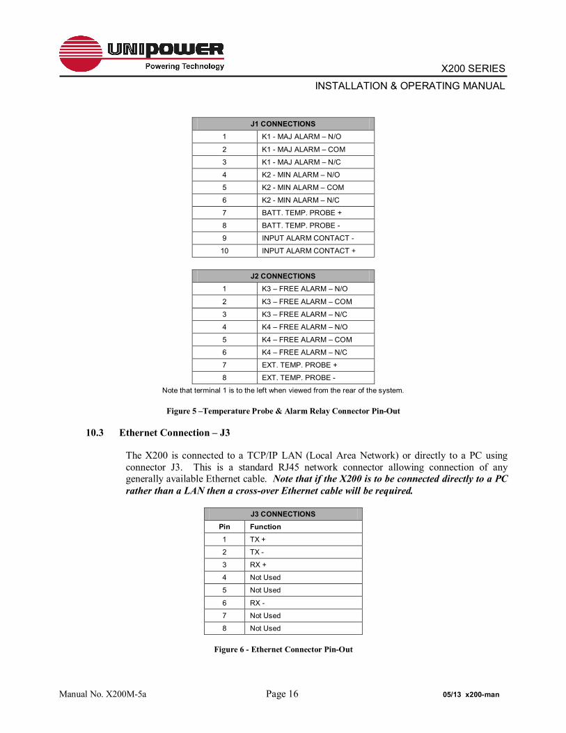
J1 CONNECTIONS 1 K1 - MAJ ALARM – N/O
2 K1 - MAJ ALARM – COM
3 K1 - MAJ ALARM – N/C
4 K2 - MIN ALARM – N/O
5 K2 - MIN ALARM – COM
6 K2 - MIN ALARM – N/C
7 BATT. TEMP. PROBE +
8 BATT. TEMP. PROBE -
9 INPUT ALARM CONTACT -
10 INPUT ALARM CONTACT +
J2 CONNECTIONS
1 K3 – FREE ALARM – N/O
2 K3 – FREE ALARM – COM
3 K3 – FREE ALARM – N/C
4 K4 – FREE ALARM – N/O
5 K4 – FREE ALARM – COM
6 K4 – FREE ALARM – N/C
7 EXT. TEMP. PROBE +
8 EXT. TEMP. PROBE -
Note that terminal 1 is to the left when viewed from the rear of the system.
Figure 5 –Temperature Probe & Alarm Relay Connector Pin-Out
10.3 Ethernet Connection – J3
The X200 is connected to a TCP/IP LAN (Local Area Network) or directly to a PC using connector J3. This is a standard RJ45 network connector allowing connection of any generally available Ethernet cable. Note that if the X200 is to be connected directly to a PC rather than a LAN then a cross-over Ethernet cable will be required.
J3 CONNECTIONS Pin Function 1 TX +
2 TX -
3 RX +
4 Not Used
5 Not Used
6 RX -
7 Not Used
8 Not Used
Figure 6 - Ethernet Connector Pin-Out
Manual No. X200M-5a Page 16 05/13 x200-man

X200 SERIES
INSTALLATION & OPERATING MANUAL
11.0 INSTALLATION
The X200 can be mounted in 19” racks by using the supplied brackets. Mounting in 23” racks requires the use of rack mount extenders. Mount it from the front of the rack using the correct offsets to align with existing rack-mounted equipment. Once mounted in the rack the following connections must be made with the unit switched off.
CAUTION: Re-read the Safety Warnings and Precautions in Section 3. All power should be OFF for the input and output loads before making connections. Connection of the X200 chassis to frame ground should be made first. If the X200 has been turned on before installation connections, it should be turned off and given a 5-minute waiting period for all internal energy storage capacitors to be discharged.
11.1 Input AC Power Connection
3-wire AC power lines should be connected to each of the input terminal block but not plugged into the AC power source. The line, neutral and ground connections should be carefully observed when making the AC connections. The AC line cord should be sized to safely carry 20 amperes AC minimum for each AC input / rectifier.
INPUT CURRENT RATINGS (FULL LOAD)
MODEL Vin AC Vout DC WATTS A@ 120Vac A@ 240Vac RBSR12/100 85-264 13.6 1360 12.5 7
RBSR24/54 85-264 27.2 1469 13.5 7.6
RBSR24/60 85-132 27.2 1469 13.5 x
RBSR24/60 180-264 27.2 1632 x 8.2
RBSR48/28 85-264 54.4 1500 14 7.5
RBSR48/37 85-132 54.4 1500 14 x
RBSR48/37 180-264 54.4 2000 x 10 NOTE: Ratings given are at nominal voltage for sizing breakers. Label rating may be greater
Manual No. X200M-5a Page 17 05/13 x200-man

X200 SERIES
INSTALLATION & OPERATING MANUAL
11.2 Checking Outputs
Turn all output circuit breakers to the OFF position. With no loads connected and without the battery connected, plug in or connect the AC input cords one at a time to the AC power source. Be sure to use the correct AC voltage for the rectifier inputs. Using a volt meter measure the DC voltage reading across the –VO and +VO bus bars connecting the rectifier section to the lower section at the rear of the unit. The voltage should be approximately 45 - 54.4, for a 48V system and scale down for both a 27.2, or 13.6VDC (depending on model), which is the factory setting. This is due to the initial DC WALK IN feature to prevent limit battery current even if batteries are not connected. To disable this feature and go directly to the float voltage see section 12.4. One by one, turn each output circuit breaker to the ON position and measure the DC voltage across the corresponding output terminals. The voltage should again read approximately 54.4, 27.2, or 13.6 volts. After each output is measured, turn OFF that circuit breaker and turn ON the next one. After measuring the last circuit, turn off that breaker and make sure that all output breakers are in the OFF position. Next, unplug or disconnect the AC input power source. Before touching any terminals wait 5 minutes for the internal storage capacitors to discharge.
11.3 Controller Section Operation and Settings
The controller is preset from the factory. To change factory default setting see section 12.
Next, make any required signal connections, controller adjustments, temperature compensation adjustment and alarm enabling settings.
WARNING: Remember to take precautions each time the system is turned on and also when connecting or disconnecting the battery. Remember that the battery presents an energy hazard at its terminals. Also remember to allow 5 minutes for internal capacitors to discharge after disconnecting the AC input power and the battery.
11.4 Connection to Battery
WARNING: Improper polarity of the battery connection may damage the power system. Take precautions when installing the battery and note that the battery cables are “hot” (live) and present an energy hazard.
With AC input unplugged, remove the three rectifier modules from the system chassis. Make sure all load circuit breakers are in the OFF position. Set the battery circuit breakers to the OFF position. Carefully connect the battery cables to the battery terminals shown in Figure 2 while observing the correct polarity.
NOTE: When the LVD option is install the BAT bus must have a voltage greater than the LVD close voltage set in the controller. This occurs when at least one rectifier is on.
Manual No. X200M-5a Page 18 05/13 x200-man

X200 SERIES
INSTALLATION & OPERATING MANUAL 11.5 Connection to Loads
With input AC power unplugged, the battery disconnected and no other power sources connected to the loads, make sure that all load circuit breakers are set to the OFF position. Connect load wires to each set of output terminals, one at a time. Note that the front panel breaker and fuse numbers directly correspond to the output terminal numbers. Be sure to connect the polarities correctly.
11.6 System Turn-On
Perform the following operations:
1. Set the battery and all load circuit breakers to the OFF position.
2. Plug in the rectifier modules.
3. Connect the AC power cables to the AC source.
4. Check that the green LED on the front panel has lit. After approximately 20 seconds for initialization the MAJ LED at least will light.
5. Set the battery circuit breaker to the ON position. Then set the load breakers to the ON position. After approximately 5 seconds the status of MAJ LEDs will change, dependent on the number of rectifiers installed.
Using the WEB browser interface described in section 12 it is now possible to check overall system status for correct operation.
NOTE: During the 30 seconds initialization period the system bus voltage will be at the factory preset level of the rectifiers. Nominally 54.4V, 27.2V or 13.6V depending on system. If the DC WALK IN is enables the controller will lower the output voltage by approximately 15% in order to limit current flowing to the batteries. During a following period of approximately 15-30 minutes the controller will ramp the system voltage up to the correct float voltage as determined by the temperature compensation algorithm.
It is important to ensure that the load current reading does not exceed the maximum capacity of the installed rectifiers or, where N+1 operation is required, the maximum capacity of one less than the total number of rectifiers installed. Note also, that the system should have been sized so that a proportion of the available rectifier capacity is allocated for battery charging. Where N+1 redundant operation is used the additional ‘spare’ rectifier will normally provide this current.
NOTE: Once normal operation is established the alarm log should be cleared.
Manual No. X200M-5a Page 19 05/13 x200-man

X200 SERIES
INSTALLATION & OPERATING MANUAL
12.0 USING THE CONTROLLER WEB BROWSER INTERFACE
The X200 is provided with a built-in WEB server which can be accessed through the TCP/IP Ethernet port using a WEB browser.
The WEB server employs Java Applets to continually scan system parameters and update the WEB page data. These same Applets return programming data to the X200 when set-up changes need to be made.
The WEB server communicates with the browser using HTTP on IP Port 80 and the Java Applets on IP Port 8888. If any firewall or proxies are configured on the LAN that the X200 is connected to it is important to ensure that these ports are open, otherwise the X200 will not respond.
Note also that a genuine Java engine must be installed on the browser PC. The latest version can be downloaded and installed for free from www.java.com.
The X200 has various network programming capabilities which allow it to be connected to almost any configuration of IP network.
The default network settings that the X200 is shipped with are:
IP Address – 192.168.0.200 Subnet Mask – 255.255.255.0 Gateway – 0.0.0.0
NOTE: When connecting directly to a PC a cross over cable is required and the network connection should be 192.168.0.x where x= a number other than 200 and is dependent on the user PC.
All pages served by the X200 built-in WEB server consist of two frames; a ‘navigation’ frame on the left hand side and an ‘information/programming’ frame which occupies the majority of the browser window.
The buttons in the ‘navigation’ frame can be used at all times to jump between the various pages. Clicking on the UNIPOWER Telecom logo at the top will navigate directly to the UNIPOWER WEB site www.unipowerco.com.
Each of the blocks of information in the ‘information/programming’ frame is a Java applet. In some cases these applets simply collect information from the X200 and presents it on-screen, in other cases the applets contain data entry fields for uploading programming information to the unit.
Note that a PC screen resolution of 1024 x 768 or higher is recommended to avoid excessive amounts of page scrolling.
The following sections describe the various WEB pages that can be viewed with the browser and give details of programming parameters that may be entered and sent to the unit.
Manual No. X200M-5a Page 20 05/13 x200-man

X200 SERIES
INSTALLATION & OPERATING MANUAL
IMPORTANT NOTE: The screenshots shown throughout this section are ‘typical’ examples. The exact data content will differ dependent on the system voltage and whether alterations from the default settings have been made. Settings can be returned to the factory defaults at any time by clicking on the ‘DEFAULT’ then ‘UPLOAD’ buttons on the relevant setup page. This action requires the level 1 password.
12.1 Controller Status
When the X200 is first accessed using a WEB browser the Controller Status page shown below is downloaded.
Figure 8 - Controller Status WEB Page (typical)
This page presents two blocks of information. The top block displays a number of system status parameters by mimicking a block of LEDs.
The bottom block of information shows the following ‘live’ data:
Bus Voltage Battery Current Rectifier Current Load Current Battery Temperature External Temperature Controller Temperature No. of Rectifiers Installed (includes all rectifiers that are present regardless of status)
NOTE: If the battery or external temperature probes are not connected a reading of 25ºC will be displayed by default.
Manual No. X200M-5a Page 21 05/13 x200-man

X200 SERIES
INSTALLATION & OPERATING MANUAL
12.2 Rectifier Status
The Rectifier Status page presents detailed information about an individual rectifier module. Two types of data are included; ‘live’ status information and ‘static’ inventory information. In addition the controller returns the I²C address as confirmation that the unit has responded.
Figure 9 - Rectifier Status WEB Page (typical)
In order to obtain status information about a particular rectifier module it is necessary first to dial in the required rectifier address according to the table below and then click on the SELECT button to confirm the request. In an expanded system there are two rectifier shelves RS1 and RS2 (see figure 3 in section 8.1). In a standard system there is only RS1.
RECTIFIER I²C ADDRESSING
Rectifier Position
RS1 lower
RS2 upper
Address Address
Left 8 16
Centre Left 9 17
Centre Right 10 18
Right 11 19
Figure 10 - Rectifier I²C Addressing
A few seconds after the SELECT button has been pressed the X200 will respond and the status and inventory information will be updated as follows:
Manual No. X200M-5a Page 22 05/13 x200-man

X200 SERIES
INSTALLATION & OPERATING MANUAL ‘Live’ data is presented in the form of 8 coloured indicator blocks to the left. A green block indicates a ‘good’ condition and a red block indicates a ‘bad’ condition. In addition the unit’s internal temperature is presented on the right.
Note that BLUEstreak Series rectifiers include two fans only and that one of the status indicator blocks will always be greyed out.
‘Inventory’ data, presented on the right below the temperature measurement includes, among other items, rectifier model number Serial Number and Revision Number.
12.2.1 Rectifier Inhibit (Shutdown)
The X200 includes a facility that enables the user to manually inhibit or shutdown individual rectifiers. This may be desirable for energy management when the load is much lower than the number of rectifiers installed.
To inhibit a rectifier first dial in the I²C address of the required unit and the click on SHUTDOWN.
To restart a rectifier that has been inhibited dial in the I²C address of the required unit and the click on RUN.
ATTENTION: Any rectifiers which have been inhibited will remain in this state until they are either restarted using the above method or the AC power is recycled.
Manual No. X200M-5a Page 23 05/13 x200-man

X200 SERIES
INSTALLATION & OPERATING MANUAL
12.3 Controller Factory Calibration
The primary purpose of the Controller Factory Calibration page is to allow UNIPOWER to setup a range of necessary calibration values to ensure correct operation.
When this page is requested and the Java applet has loaded a dialog requesting the Level 2 Passcode is presented. Once the passcode has been entered click ENTER and the page will then be updated with current values after a few seconds.
Figure 11 - Controller Factory Calibration WEB Page (typical)
NOTE: It should not normally be necessary for changes to be made to this page other than to change the passcodes if so desired.
The factory set passcodes are:
Passcode 1 – 111 Passcode 2 – 123
Manual No. X200M-5a Page 24 05/13 x200-man
X200 SERIES
INSTALLATION & OPERATING MANUAL
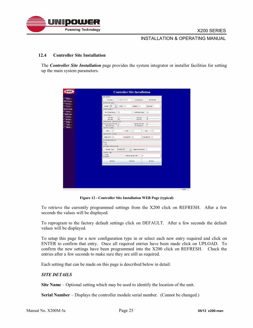
12.4 Controller Site Installation
The Controller Site Installation page provides the system integrator or installer facilities for setting up the main system parameters.
Figure 12 - Controller Site Installation WEB Page (typical)
To retrieve the currently programmed settings from the X200 click on REFRESH. After a few seconds the values will be displayed.
To reprogram to the factory default settings click on DEFAULT. After a few seconds the default values will be displayed.
To setup this page for a new configuration type in or select each new entry required and click on ENTER to confirm that entry. Once all required entries have been made click on UPLOAD. To confirm the new settings have been programmed into the X200 click on REFRESH. Check the entries after a few seconds to make sure they are still as required.
Each setting that can be made on this page is described below in detail:
SITE DETAILS
Site Name – Optional setting which may be used to identify the location of the unit.
Serial Number – Displays the controller module serial number. (Cannot be changed.)
Manual No. X200M-5a Page 25 05/13 x200-man

X200 SERIES
INSTALLATION & OPERATING MANUAL SYSTEM VOLTAGES
System – Dial in the Nominal BATTERY (system) voltage; 12V, 24V or 48V.
Float – Enter the float voltage in accordance with the specifications of the batteries that are being employed with the system.
Equalize – Enter the equalization voltage in accordance with the specifications of the batteries that are being employed with the system.
Equ Time – Enter the desired time that the system should remain in equalize mode in accordance with the specifications of the batteries that are being employed with the system. This is a manual start function.
SYSTEM SHUNTS
Rect Shunt Amps – This is the 50mV Full-Scale rating for the internal shunt that is used to measure the total rectifier current. THIS SETTING SHOULD NOT BE CHANGED.
Load Shunt Amps – This is the 50mV Full-Scale rating for the shunt that is used to measure the total load current. THIS SETTING SHOULD NOT BE CHANGED.
LVD SETTINGS
LVD1 Off – Enter the voltage at which the LVD1 contactor will open during a battery discharge. The factory default setting is that recommended for most sealed lead acid batteries.
LVD1 On – Enter the voltage at which the LVD1 contactor will close once bus voltage is restored. The factory default setting is recommended for most sealed lead acid batteries.
LVD2 Off & LVD2 On – These settings are not required for the X200.
TEMPERATURE COMPENSATION
Temp Comp (mV/°C/Cell) – Enter the temperature compensation slope value in accordance with the specifications of the batteries that are being employed with the system.
Number Of Cells – Enter the total number of battery cells. (i.e. a 48V battery enter #24)
Max Temp (°C) – Enter the maximum temperature at which temperature compensation may be applied. Above this temperature the X200 will cease to apply further compensation to the float voltage.
Min Temp (°C) – Enter the minimum temperature at which temperature compensation may be applied. Below this temperature the X200 will cease to apply further compensation to the float voltage.
ATTENTION: VERIFY THE OVA AND UVA VALUES ARE NOT EXCEEDED OTHERWISE ALARMS CAN BE GENERATED DURING TEMPERATURE COMPENSATION.
Manual No. X200M-5a Page 26 05/13 x200-man
X200 SERIES
INSTALLATION & OPERATING MANUAL VOLTAGE ALARMS
OVA – Enter the voltage above which the Over-Voltage Alarm will be triggered.
UVA – Enter the voltage below which the Under-Voltage Alarm will be triggered.
EVA – Enter the voltage below which the End-Voltage Alarm will be triggered.
TEMPERATURE ALARMS
Battery OT – Enter the temperature at which the battery Over-Temperature alarm will be triggered.
External OT – Enter the temperature at which the external Over-Temperature alarm will be triggered.
Controller OT – Enter the temperature at which the controller’s internal Over-Temperature alarm will be triggered. THIS SETTING SHOULD NOT NORMALLY BE CHANGED.
DC WALK-IN
ON (Default) – Causes the controller to slowly ramp up the DC rectifier voltage when AC is applied. The voltage will rise from approximately 45V (for 48V systems), 22V (for 24V systems) and 11V (for 12V systems) up to the float voltage. The ramp-up time is several minutes and cannot be adjusted. The purpose of this feature is to avoid initially large battery charging currents.
OFF – Causes the controller to program all rectifiers to the float voltage almost immediately after AC is applied. Battery charging current will only be limited by the current limit of the rectifiers.”
AC MONITOR
In lieu of direct AC monitoring the X200 controller monitors the number of installed rectifiers. When all AC power is removed the rectifier good count reaches zero a ACF alarm is generated.
RECTIFIER CONFIGURATION
Rectifier Type – This selects the type of rectifier installed in the system from the drop-down list. In the X200 this is factory pre-set to RBSR and SHOULD NOT BE CHANGED.
Minimum Rectifiers – Enter the minimum number of rectifiers that is required to provide sufficient current to the load and to simultaneously re-charge the batteries from a fully discharged state in the desired time according to the specification of the batteries being employed with the system.
CURRENT LIMIT
Select the appropriate button for ENABLE or DISABLE as required.
Battery Charge Limit – When enabled enter the maximum desired battery charge current the system can provide during a recharge cycle
Using this setting the X200 will intelligently control the rectifier float voltage such that the battery charge current never exceeds the set value.
Manual No. X200M-5a Page 27 05/13 x200-man

X200 SERIES
INSTALLATION & OPERATING MANUAL
12.5 Alarm Configuration
The Alarm Configuration page presents a matrix of tick boxes which are used to programme how certain system conditions affect the actions of the alarm relays and front panel LEDs. It is also used to define the ‘good’ condition (polarity) of the auxiliary digital input.
Figure 13 - Alarm Configuration WEB Page (typical)
12.5.1 Alarm Matrix Programming
K1 MAJ – An item ticked in this column will enable the MAJOR alarm relay when active. Any item that is considered to represent a condition which should be acted upon immediately should be ticked.
K2 MIN – An item checked in this column will enable the MINOR alarm relay when active. Any item that is considered to represent a condition that can wait for action at a later time should be ticked.
K3 & K4 – USER PROGRAMMABLE. A ticked item in any of these columns will activate the relevant auxiliary alarm relay.
Note that K5 – K8 are not installed in the X200 system.
Manual No. X200M-5a Page 28 05/13 x200-man

X200 SERIES
INSTALLATION & OPERATING MANUAL MAJ LED – An item ticked in this column will enable the MAJOR alarm LED when
active.
MIN LED – An item ticked in this column will enable the MINOR alarm LED when active.
ACF LED – An item ticked in the column will activate the ACF LED when the condition occurs.
RFA LED – An item ticked in the column will activate the RFA LED when the condition occurs
OVA LED – An item ticked in the column will activate the OVA LED when the condition occurs.
UVA LED – An item ticked in the column will activate the UVA LED when the condition occurs.
LVD LED – An item ticked in the column will activate the LVD LED when the condition occurs.
FUSE (CB) LED – An item ticked in the column will activate the FUSE LED when the condition occurs for a FUSE or CIRECUIT BREAKER
Note: The following LEDs are not fitted on the X200 but the function will show a valid condition on the controller status WEB page.
OTA LED – An item ticked in the column will activate the OTA LED when the condition occurs.
EVA LED – An item ticked in the column will activate the EVA LED when the condition occurs.
CHKB LED – Not used in the X200
COM LED – An item ticked in the column will activate the COM LED when the condition occurs.
FLT LED – An item ticked in the column will activate the FLT LED when the condition occurs.
EQU LED – An item ticked in the column will activate the EQU LED when the condition occurs.
BTST LED – Not used in the X200
EMAIL – When the email reporting feature is activated ticking an item in this column results in an email message being sent immediately.
Manual No. X200M-5a Page 29 05/13 x200-man

X200 SERIES
INSTALLATION & OPERATING MANUAL 12.5.2 Aux. Input Polarities
By selecting the NO or NC radio buttons for the AUX 3 input the ‘good’ condition can be set to either Normally Open or Normally Closed respectively.
NOTE THAT THE LVD AND FUSE SETTINGS ARE PRESET TO N.O. AND SHOULD NOT BE CHANGED.
AUX 4 to AUX 8 are not fitted on the X200 system.
Once the required alarm and input polarity settings have been selected it is necessary to click on the UPLOAD button to store the new settings in the unit’s memory. To confirm that the new settings have been received and programmed click on the REFRESH button and wait a few seconds for the unit to respond. If no changes are apparent then the unit has been successfully reprogrammed.
To return the unit to the factory default settings click on the DEFAULT button.
Manual No. X200M-5a Page 30 05/13 x200-man

X200 SERIES
INSTALLATION & OPERATING MANUAL
12.6 Comms
Clicking on the Comms button loads to Controller Network Settings page. This page is used to setup the Ethernet and E-Mail communications settings.
Figure 14 - Controller Network Settings (typical)
12.6.1 Ethernet Settings
12.6.1.1 IP Address
This setting defines the IP Address for the controller.
The default factory setting of 192.168.0.200 is a designated ‘private’ IP Address commonly used in IP based local area networks behind proxies, NAT routers or network bridges.
To enter a new IP address use the up/down arrows to dial in the required numbers or type them directly into the boxes as required. It is important to press the ENTER key on completion.
Manual No. X200M-5a Page 31 05/13 x200-man

X200 SERIES
INSTALLATION & OPERATING MANUAL
12.6.1.2 Subnet Mask
This setting defines the Subnet Mask associated with the above IP Address.
The default factory setting is 255.255.255.0.
To alter the Subnet mask use the up/down arrows to dial in the required numbers or type them directly into the boxes as required. It is important to press the ENTER key on completion.
12.6.1.3 Default Gateway
This setting defines the Network Gateway to which the controller will route all IP traffic that is destined for any location outside the LAN to which it is connected. This setting would normally be the address for the Proxy, NAT Router or Bridge that routes network traffic to the Internet or other WAN segments.
The default factory setting is 0.0.0.0, i.e. all traffic is retained within the LAN environment.
To alter the Default Gateway use the up/down arrows to dial in the required numbers or type them directly into the boxes as required. It is important to press the ENTER key on completion.
12.6.2 E-Mail Settings
12.6.2.1 Mail Host
This setting is the IP Address of the E-Mail Server that will route SMTP messages sent by the controller.
To set this address use the up/down arrows to dial in the required numbers or type them directly into the boxes as required. It is important to press the ENTER key on completion.
12.6.2.2 Mail Service
Select the ETHERNET radio button to switch on the E-Mail alarm facility, select the DISABLE radio button to switch it off.
Manual No. X200M-5a Page 32 05/13 x200-man

X200 SERIES
INSTALLATION & OPERATING MANUAL
12.6.2.3 E-Mail 1, 2 & 3
The X200 is able to send alarm messages to up to three unique email addresses.
Type in the desired address in the E-Mail 1 box using the normal name@domain format and press the ENTER key to confirm.
Repeat as required for E-Mail 2 and E-Mail 3.
12.6.2.4 Controller E-Mail
The X200 requires an email address of its own to send email alarm messages. Note, however, that it is unable to receive messages sent to this address.
Type in the desired address in the Controller E-Mail box using the normal name@domain format and press the ENTER key to confirm.
Once all desired Ethernet and E-Mail settings have been entered click on the UPLOAD button to programme them into the controller. To confirm successful programming on these setting click on the REFRESH button, wait a few seconds for the unit to respond and then ensure that the desired settings are returned by the unit.
CAUTION: Once a new IP Address has been uploaded it will be necessary to redirect the browser to this new address in order to access the WEB pages.
Manual No. X200M-5a Page 33 05/13 x200-man

X200 SERIES
INSTALLATION & OPERATING MANUAL
12.7 Alarm Log
The Alarm Log page can be used to view a history of alarm and other conditions that have occurred.
To load the current log file click on REFRESH. After a few seconds the log data will be loaded.
To clear the log click on the CLEAR button, the refresh the page click on the REFRESH button.
Figure 15 - Controller Alarm Log WEB Page (typical)
Manual No. X200M-5a Page 34 05/13 x200-man

X200 SERIES
INSTALLATION & OPERATING MANUAL
12.8 Control
The Controller Control Panel page is used to remotely switch the system between FLOAT and EQUALIZE modes. This page displays various system status functions enabling the operator to monitor these system parameters from a remote location.
To set the system to equalize mode click on the EQUALIZE button. After a few seconds the unit will respond by switching off the FLT LED indicator and switching on the EQU LED indicator.
To return the system to float mode, click on the FLOAT button. The unit will respond by returning the FLT and EQU LED indicators to their normal state.
Note that if the unit is not returned to float mode manually it will be returned automatically after the pre-programmed time has elapsed.
Figure 16 - Controller Control Panel WEB Page (typical)
Manual No. X200M-5a Page 35 05/13 x200-man

X200 SERIES
INSTALLATION & OPERATING MANUAL
12.9 System
The Controller System Settings page enables a user to alter the controller’s real-time clock date and time settings. New date and time settings can be entered manually or automatically synchronised with a ‘host’ system.
Figure 17 - Controller System Settings WEB Page (typical)
12.9.1 Manual Setting
To enter a new date and/or time manually either use the up/down buttons to dial in the desired settings or type them directly into the required boxes. Press the ENTER key in each case to confirm.
Once the desired settings have been enter click on the SET button to upload them.
12.9.2 Automatic Setting
To synchronise the date and time with the computer being used to access the controller click on the SYNC button to load the new settings from the computer and then click on the SET button to upload them.
To update this page with the controller’s current date and time click on the GET button.
Manual No. X200M-5a Page 36 05/13 x200-man
X200 SERIES
INSTALLATION & OPERATING MANUAL
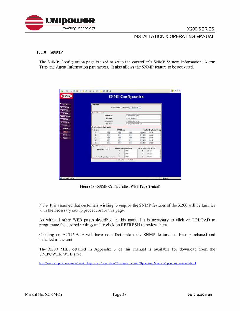
12.10 SNMP
The SNMP Configuration page is used to setup the controller’s SNMP System Information, Alarm Trap and Agent Information parameters. It also allows the SNMP feature to be activated.
Figure 18 - SNMP Configuration WEB Page (typical)
Note: It is assumed that customers wishing to employ the SNMP features of the X200 will be familiar with the necessary set-up procedure for this page.
As with all other WEB pages described in this manual it is necessary to click on UPLOAD to programme the desired settings and to click on REFRESH to review them.
Clicking on ACTIVATE will have no effect unless the SNMP feature has been purchased and installed in the unit.
The X200 MIB, detailed in Appendix 3 of this manual is available for download from the UNIPOWER WEB site:
http://www.unipowerco.com/About_Unipower_Corporation/Customer_Service/Operating_Manuals/operating_manuals.html
Manual No. X200M-5a Page 37 05/13 x200-man

X200 SERIES
INSTALLATION & OPERATING MANUAL
12.11 Help
The Controller Help Page provides a few quick reminder notes. For more detailed help the user is referred to this manual.
Figure 19 - Controller Help WEB Page (typical)
12.12 About
The About UNIPOWER Telecom page provides contact information in case additional technical or other support is required.
Figure 20 - About UNIPOWER Telecom WEB Page (typical)
Manual No. X200M-5a Page 38 05/13 x200-man

X200 SERIES
INSTALLATION & OPERATING MANUAL
Appendix 1 – SNMP MIB Information.
The SNMP feature provides status read-out and alarm trapping only. All parameters described in this appendix are therefore read-only.
Refer to the appropriate sections earlier in the main body of this manual for system set-up.
Parameters for UNIPOWER X200 Remote Access Controller MIB
1. Voltages
Bus Voltage - Description: Live data giving actual voltage of system bus.
2. Currents
Battery Current - Live data giving actual current drawn from or into battery string(s).
Rectifier Current - Live data giving actual current drawn from rectifier power supply system.
Load Current - Live data giving actual current delivered to the load.
3. Temperatures
Battery Temperature - Live data giving actual temperature of battery string.
External Temperature - Live data giving actual temperature of external sensor.
Controller Temperature - Live data giving actual temperature within the controller enclosure.
4. Rectifier Info
Number of Rectifiers - Live data giving number of rectifiers detected by the controller.
Manual No. X200M-5a Page 39 05/13 x200-man

X200 SERIES
INSTALLATION & OPERATING MANUAL
5. Auxiliary Inputs
These are all part of one status flag held within the controller.
Digital Input 1 factory set (Low Voltage Disconnect State) Digital Input 2 factory set (Fuse/Breaker State) Digital Input 3 USER PROGRAMMABLE or optional LVD BYPASS Digital Input 4 NOT USED Digital Input 5 NOT USED Digital Input 6 NOT USED Digital Input 7 NOT USED Digital Input 8 NOT USED
6. Alarms
These are all part of one alarm status flag held within the controller.
ACFAIL - Indicates all the rectifiers have failed (i.e. rectifier good = 0) Note: there is no direct sense of the AC line..
MAJOR - Indicates that a major alarm condition requiring immediate attention has been detected by the controller.
MINOR - Indicates that a minor alarm condition requiring attention at the next scheduled maintenance has been detected by the controller.
SINGLE RECTIFIER FAILURE (SRFA) - The controller has detected that a single rectifier has failed
MULTI RECTIFIER FAILURE (MRFA) - The controller has detected that multiple rectifiers have failed.
OVER TEMPERATURE ALARM (OTA) - The controller has detected an over temperature condition on battery/external/controller temperature sensor.
OVER VOLTAGE ALARM (OVA) - The controller detected an over voltage condition on the bus.
UNDER VOLTAGE ALARM (UVA) - The controller detected an under voltage condition on the bus.
END VOLTAGE ALARM (EVA) - The controller has detected an End Voltage condition, i.e. the batteries are near end of discharge.
LOW VOLTAGE DISCONNECT ALARM (LVD) - The controller detected that the LVD is open.
FUSE ALARM - The controller has detected that a fuse or breaker is open.
Manual No. X200M-5a Page 40 05/13 x200-man

X200 SERIES
INSTALLATION & OPERATING MANUAL CHECK BATTERY (CHKBAT) - The controller has detected a fault with the battery string(s) either
temperature or current related.
COMMUNICATION FAULT (COMM) - The controller detected a problem with the internal I²C bus.
7. Settings
OVER VOLTAGE ALARM SETTING - Setting for over voltage alarm.
UNDER VOLTAGE ALARM SETTING - Setting for under voltage alarm.
END VOLTAGE ALARM SETTING - Setting for end voltage alarm.
LVD1OFF SETTING - Setting for voltage at the point where LVD1 will be shut off.
LVD1ON SETTING - Setting for voltage at the point where LVD1 will be turned on.
LVD2OFF SETTING – NOT USED in the X200.
LVD2ON SETTING - NOT USED in the X200.
FLOAT VOLTAGE - Voltage setting for the bus in float mode (modified by temp. compensation).
EQUALIZE VOLTAGE - Voltage setting for the bus in equalization mode.
NOMINAL SYSTEM VOLTAGE - The nominal system voltage (12, 24 or 48).
CONTROLLER OVER TEMPERATURE ALARM - The controller temperature, (Celsius) is above which an over temperature alarm will activate.
BATTERY OVER TEMPERATURE ALARM - The battery temperature, in degrees Celsius, above which an over temperature alarm will activate.
EXTERNAL OVER TEMPERATURE ALARM - The external temperature, in degrees Celsius, above which an over temperature alarm will activate.
TEMPERATURE COMPENSATION SLOPE - The parameter applied, in millivolts/°C/cell, to the float voltage to achieve temperature compensation.
TEMPERATURE COMPENSATION MAX TEMPERATURE - The temperature above which no further temperature compensation will be applied.
TEMPERATURE COMPENSATION MIN TEMPERATURE - The temperature below which no further temperature compensation will be applied.
Manual No. X200M-5a Page 41 05/13 x200-man

X200 SERIES
INSTALLATION & OPERATING MANUAL
8. Identification
SITE NAME - Holds the name of the site/system.
SERIAL NUMBER - Holds the serial number of the site/system.
9. SNMP Traps
The X200 will issue a trap if any of the alarm conditions mentioned above are activated.
A trap will also be issued when an alarm condition is cleared.
To obtain a copy of the latest X200 MIB download it from:
http://unipowerco.com/operating-manuals
Or contact one of our sales offices.
Manual No. X200M-5a Page 42 05/13 x200-man

X200 SERIES
INSTALLATION & OPERATING MANUAL
13.0 USING THE FRONT PANEL DISPLAY ON THE X200 CONTROLLER.
13.1 LCD ALPHANUMERIC DISPLAY:
The 16 character, 2 line LCD alphanumeric display provides a menu structure in conjunction with the keypad enabling the status of a range of system parameters to be displayed and programmed.
Figure 21 – LCD Default Display Condition
During normal operation the system Bus Voltage and Rectifier Current will be displayed
13.2 KEYPAD
The keypad is used in conjunction with the alphanumeric LCD display to navigate through the menu structure and to set system parameters as required.
Figure 22 – Keypad Description
When the system is in normal display mode this key will present a password entry screen. Any other time pressing this key will return the system to normal display mode.
Used to confirm entry of a new setting once it has been set on the display.
Used to cancel the last entry. Pressing this key several times will return the display to the top STATUS menu.
Used to enter the displayed menu or parameter setup.
Used to navigate up and down through the menus and to scroll through the alphabet or numbers when programming a parameter.
Used to select the next or previous character or digit when programming a parameter
Manual No. X200M-5a Page 43 05/13 x200-man

X200 SERIES
INSTALLATION & OPERATING MANUAL
13.3 ACCESSING SYSTEM STATUS & PROGRAMMING VIA THE FRONT PANEL.
The Front Panel Alphanumeric LCD display along with the keypad can access all of the status and programming functions of the X200 with the exception of the alarm matrix and optional SNMP, both of which are only accessible through the WEB server interface using a WEB browser.
A description of the complete menu structure starting from the normal operating display follows:
NOTE: There will be a slight delay between the time that a key is pressed and that time that the display is updated. This is due to the manner in which the microprocessor scans the peripheral devices in sequence.
13.3.1 Press to access the level 1 passcode display
13.3.2 Using the keys dial in the level 1 passcode and press to confirm
The level 1 passcode is factory set to ‘111’.
At this point you will have access to the top level menus.
To enter each menu press and to exit press .
Press at any time to return to the normal operating display
13.4 The status menu displays the following system parameters:
Press or to scroll through the status menu
Displays the system bus voltage.
Displays the total rectifier current.
Displays the total load current. The X200 utilizes two system shunts to measure total rectifier and total load current. Total load battery is then calculated using these two measurements.
Displays the battery current. A positive value indicates a charging current while a negative value indicates a discharge current, when the system is running on batteries.
Displays the battery temperature. Battery temperature is measured using a probe supplied with the X200 that is attached to one of the battery terminals.
Displays the X200 control unit’s internal temperature.
Manual No. X200M-5a Page 44 05/13 x200-man

X200 SERIES
INSTALLATION & OPERATING MANUAL
Displays the temperature measured by an optional measurement probe. This probe would generally be installed in a location appropriate to obtain a measure of ambient temperature in the equipment room in which a power system is installed.
AC1/AC2/AC3 not used in the X200
Displays the system date and time. The X200contains a real-time clock with its own internal battery supply. This clock can be synchronized with the real-time clock of any system connected through the WEB interface.
Displays the number of rectifiers installed in the power system. The max number for the X200 is 8.
13.5 I nst al l
The Install menu is used to set up the following parameters at the time of system installation:
Press or to scroll through the Install menu.
Press enable the set-up cursor then use the keys to dial in the required setting.
Press to confirm.
Optional setting which may be used to identify the location of the unit.
Displays the unit serial number.
Sets the nominal float voltage in accordance with the specifications of the batteries that are being employed with the system.
Sets the 50mV full-scale rating for the shunt used to measure total rectifier current.
Sets the 50mV full-scale rating for the shunt used to measure total load current.
Sets the equalisation voltage in accordance with the specifications of the batteries that are being employed with the system.
8
Si t e Namecoral spr i ngs f l
Ser i al NumberWWYY999999
Set Fl oat V54. 40
Set Rect . Amps0050
Set Load Amps0150
Set Equ. Vol t s56. 70
Manual No. X200M-5a Page 45 05/13 x200-man

X200 SERIES
INSTALLATION & OPERATING MANUAL
Set LVD1 Of f46. 0
Sets the voltage at which the Over Voltage Alarm will trigger. This setting is determined by the maximum voltage that the load or the batteries will tolerate, whichever is the lowest.
Sets the voltage at which the Under Voltage Alarm will trigger. This setting is generally used to provide an early warning when the system is running on batteries that the charge level is getting low.
Sets the voltage at which the End Voltage Alarm will trigger. This setting provides a warning when the system is running on batteries that the charge level is close to the minimum safe level.
Set the voltage at which the LVD1 contact will be opened as the battery voltage falls during a discharge cycle. (LVD2 not used)
Set the voltage at which the LVD1 contact will be closed once the AC supply has been restored. (LVD2 not used)
Sets the temperature, as measured by the battery temperature probe, at which the Battery Over-Temperature Alarm will be triggered.
Sets the temperature, as measured by the optional external temperature probe, at which the External Over-Temperature Alarm will be triggered.
Set Ext . OTA50. 0
Set Bat t . OTA40. 0
Set LVD1 On46. 5
Set EVA Vol t s43. 00
Set OVA Vol t s59. 00
Set UVA Vol t s46. 00
Manual No. X200M-5a Page 46 05/13 x200-man

X200 SERIES
INSTALLATION & OPERATING MANUAL
Set Cont . OTA70. 0
Sets the point at which the Controller Over-Temperature Alarm will be triggered. This should not be set above 70C as this is the maximum specified internal operating temperature of the unit.
Sets the temperature compensation slope in accordance with the battery specifications that are being employed with the system.
Sets the maximum allowable battery temperature in accordance with the specifications of the batteries that are being employed with the system. Above this temperature the compensation feature will cease to make adjustments to the float voltage.
Sets the minimum allowable battery temperature in accordance with the specifications of the batteries that are being employed with the system. Below this temperature the compensation feature will cease to make adjustments to the float voltage.
Sets the total number of battery cells that are being employed with the system. (example for a -48V battery system # = 24)
Sets the minimum number of rectifiers that are required to provide sufficient load current combined with the battery recharge current required to recover from a fully discharged state.
Matches the X200 with the characteristics of the rectifiers installed in the system. (Default for the X200 is RBSR only)
Sets the X200 for use with a 48V, 24V or 12V system.
Sets the time in the internal real-time clock.
Sets the date in the internal real-time clock.
Sets the time, in minutes, that the system will remain in equalization mode after the equalize mode has been set.
AC Mon. Present3
NOT USED
Set AC Ext . Mi n.264
NOT USED .
Set AC Ext . Max.085
NOT USED.
Set Temp. Comp.+00. 0
Set TC Max Temp.40. 0
Set TC Mi n Temp.+00. 0
Set # of cel l s16
Set Mi n # Rect s.005
Set Rect . TypeRRS
Set Sys. Type48
Set Ti me HH: MM22: 25
Set MM/ DD/ YYYY01/ 01/ 2005
Set Equ. Ti me001
Manual No. X200M-5a Page 47 05/13 x200-man

X200 SERIES
INSTALLATION & OPERATING MANUAL
13.6 Cal i brat e
The Calibrate menu is used to setup the following parameters which relate to matching the X200 to the rectifiers, shunts and temperature probes.
ATTENTION: X200 IS CALIBRATED AT THE FACTORY PRIOR TO SHIPPING AND UNDER NORMAL CIRCUMSTANCES DOES NOT REQUIRE REPEAT CALIBRATION.
• IN ADDITION, THE TWO ACCESS PASSCODES MAY BE SET FROM THIS MENU. The majority of these parameters are factory pre-set and should not require alteration.
o IT IS RECOMMENDED TO USE THE WEB BROWSER INTERFACE TO CHANGE PASSCODES TO AVOID IMPROPER KEY ENTRY .
Press to access the level 2 passcode display Ent er Passcode 2000
Using the keys dial in the level 2 passcode and press to confirm.
The level 2 passcode is factory set to ‘123’.
Press or to scroll through the Calibrate menu.
Press enable the set-up cursor then use the keys to dial in the required setting.
Press to confirm.
Set Vol t Gai n388. 89
Sets the gain of the internal A/D measuring bus voltage.
Set Vol t Of f set00. 27
Sets the offset of the internal A/D measuring bus voltage.
Set Rect I Gai n099. 40
Sets the gain of the internal A/D measuring total rectifier current.
Set Rect I Of f st-002. 79
Sets the offset of the internal A/D measuring total rectifier current.
Set Load I Gai n099. 69
Sets the gain of the internal A/D measuring total load current.
Set Load I Of f st-003. 00
Sets the offset of the internal A/D measuring total load current.
Set B Tmp. Gai n0. 01938
Sets the gain of the internal A/D measuring battery temperature.
Manual No. X200M-5a Page 48 05/13 x200-man

X200 SERIES
INSTALLATION & OPERATING MANUAL Set B Tmp. Of f st276. 8
Sets the offset (in Kelvin) of the internal A/D measuring battery temperature.
Set E Tmp. Gai n0. 01938
Sets the gain of the internal A/D measuring external temperature.
Set E Tmp. Of f st277. 0
Sets the offset (in Kelvin) of the internal A/D measuring external temperature.
Set Set poi nt 12V13. 5
Sets the rectifier calibration point for 12V rectifiers.
Set Sl ope 12V0. 0168
Sets the D/A slope characteristic for 12V rectifiers.
Set Set poi nt 24V27. 1
Sets the rectifier calibration point for 24V rectifiers.
Set Sl ope 24V0. 0336
Sets the D/A slope characteristic for 24V rectifiers.
Set Set poi nt 48V54. 3
Sets the rectifier calibration point for 48V rectifiers.
Set Sl ope 48V0. 0672
Sets the D/A slope characteristic for 48V rectifiers.
Set Passcode 1000
Sets the level 1 passcode to any value between 000 and 999.
Set Passcode 2000
Sets the level 2 passcode to any value between 000 and 999.
Manual No. X200M-5a Page 49 05/13 x200-man

X200 SERIES
INSTALLATION & OPERATING MANUAL
13.7 Funct i on
The Function menu is used to set the system into either Float or Equalize mode.
Press or to select the desired function.
Press to confirm.
St art Fl oat
Sets the system into the normal float charge mode. This is the default setting when the system is first switched on.
St art Equal i ze
Sets the system into equalize charge mode. The system will automatically return to the default Float mode when the time set for equalization in the Install menu is reached or when the Start Float function above is reset.
13.8 Net work Set t i ngs
The Network Settings menu is used to setup the various IP addresses required by the system to serve its WEB pages over the Ethernet TCP/IP connection.
Press or to scroll through the Network Settings menu.
Press enable the set-up cursor then use the keys to dial in the required setting.
Press to confirm.
Sets the unit’s IP Address. The factory default is private address 192:168:000:200
Sets the unit’s IP Subnet Mask. The factory default is 255:255:255:0000
Sets the IP address for the mail host which provides an SMTP relay for the unit to send alarm messages. The target email addresses are set using the Communications WEB page. The factory default is 000:000:000:000, not set.
Sets the IP address for a network gateway if required. The factory default is 000:000:000:000, not set.
Gat eway I P000: 000: 000: 000
Mai l Host000: 000: 000: 000
Subnet Mask255: 255: 255: 000
I P Address192: 168: 000: 001
Manual No. X200M-5a Page 50 05/13 x200-man

X200 SERIES
INSTALLATION & OPERATING MANUAL
Sets the service that will be used to transfer emails when required. The factory default is ‘unset’. If the email service is to be used then this must be set to ‘Eth’.
Displays the unique Mac Address identity of the Ethernet control IC installed in the x200.
14.0 CUSTOMER SPECIALS
14.1 LVD BYPASS / BATTLE SHORT
When the optional LVD (Low voltage disconnect) is installed there may be situations where the operation of the LVD needs to be bypass to prevent disconnection of the battery, even in the event of battery damage to extend run time to the maximum the batteries can supply.
For this operation a single pole / double throw switch can be installed at the rear of the X200.
In the “OFF” position the LVD operates normally. In the “ON” position the LVD is disabled and will not open even if the LVD open voltage criteria is met.
NOTE: To prevent the LVD from opening the BYPASS MUST be engaged to the “ON” position while the bus voltage is greater than the LVD open set point. Once the LVD is open engaging the BYPASS will not close the LVD. To close the LVD a bus voltage greater than the “LVD ON” set point must be applied.
Emai l TransportEt h
Mac Address88: 88: 88: 88: 88: 8
Manual No. X200M-5a Page 51 05/13 x200-man
X200 SERIES
INSTALLATION & OPERATING MANUAL
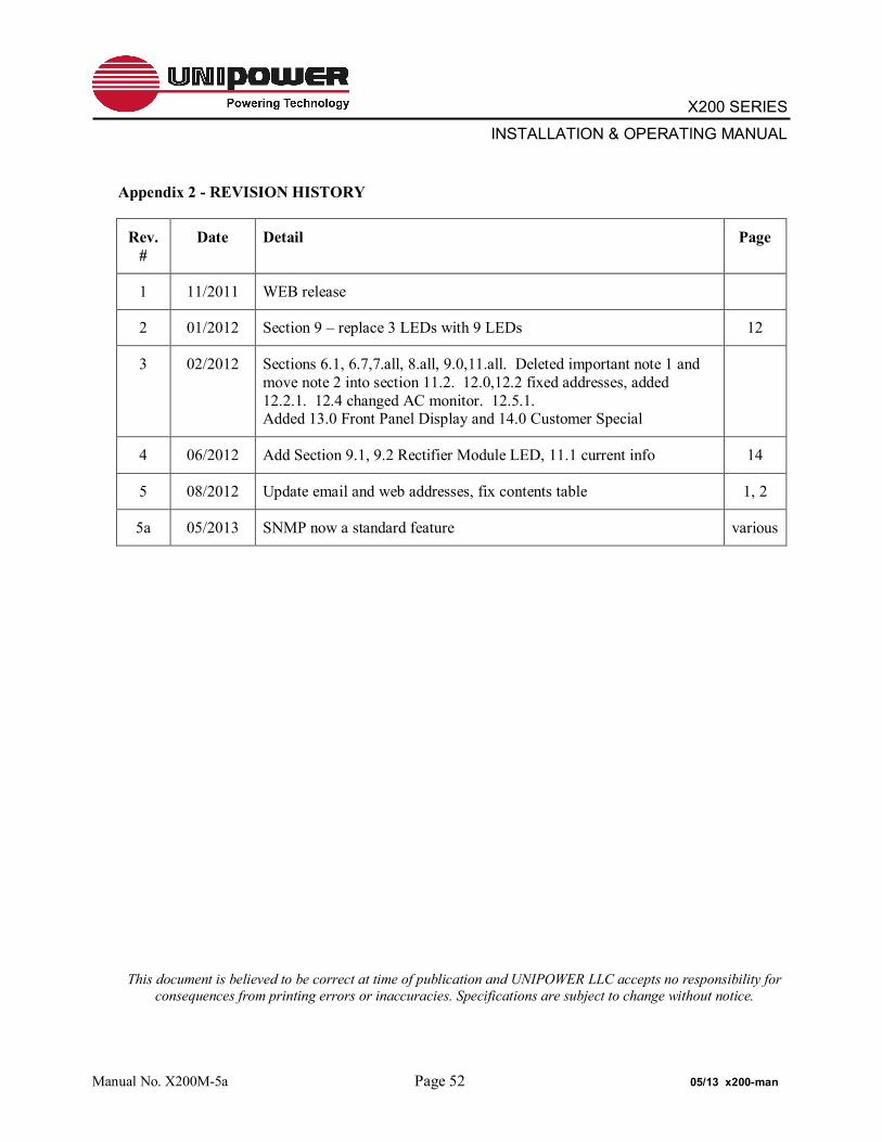
Appendix 2 - REVISION HISTORY
Rev. #
Date Detail Page
1 11/2011 WEB release
2 01/2012 Section 9 – replace 3 LEDs with 9 LEDs 12
3 02/2012 Sections 6.1, 6.7,7.all, 8.all, 9.0,11.all. Deleted important note 1 and move note 2 into section 11.2. 12.0,12.2 fixed addresses, added 12.2.1. 12.4 changed AC monitor. 12.5.1. Added 13.0 Front Panel Display and 14.0 Customer Special
4 06/2012 Add Section 9.1, 9.2 Rectifier Module LED, 11.1 current info 14
5 08/2012 Update email and web addresses, fix contents table 1, 2
5a 05/2013 SNMP now a standard feature various
This document is believed to be correct at time of publication and UNIPOWER LLC accepts no responsibility for consequences from printing errors or inaccuracies. Specifications are subject to change without notice.
Manual No. X200M-5a Page 52 05/13 x200-man