X-SEL Serial Communication Protocol Specification (Format B) · parameter is available in X-SEL-J/K...
79
-1/78- [Applicable Models] X-SEL-J/K Main Application V0.99 X-SEL-JX/KX Main Application V0.42 TT Main Application V0.18 X-SEL-P/Q Main Application V0.69 X-SEL-PX/QX Main Application V0.33 SSEL Main Application V0.18 ASEL/PSEL Main Application V0.09 X-SEL Serial Communication Protocol Specification (Format B) ⎯ Sixth Edition ⎯ September 26, 2007
Transcript of X-SEL Serial Communication Protocol Specification (Format B) · parameter is available in X-SEL-J/K...
-1/78-
[Applicable Models] X-SEL-J/K Main Application V0.99 X-SEL-JX/KX Main Application V0.42 TT Main Application V0.18 X-SEL-P/Q Main Application V0.69 X-SEL-PX/QX Main Application V0.33 SSEL Main Application V0.18 ASEL/PSEL Main Application V0.09
X-SEL
Serial Communication Protocol Specification (Format B)
⎯ Sixth Edition ⎯ September 26, 2007
-2/78-
Table of Contents
1. OVERVIEW ....................................................................................................................................6
2. TRANSMISSION CONTROL PROCEDURE..................................................................................7
3. OUTLINE OF MESSAGE...............................................................................................................9
4. MESSAGE DETAILS....................................................................................................................11
4-1. Message List.........................................................................................................11
4-2. Error Response ....................................................................................................13
4-3. Message Details ...................................................................................................14
4-3-1. Error Response........................................................................................................14
4-3-2. Test Call....................................................................................................................15
4-3-3. Version Code Query ................................................................................................16
4-3-4. Number of Effective Point Data Query...................................................................17
4-3-5. Effective Point Data Query......................................................................................18
4-3-6. Input Port Query ......................................................................................................19
4-3-7. Output Port Query ...................................................................................................20
4-3-8. Flag Query................................................................................................................21
-3/78-
4-3-9. Integer Variable Query ............................................................................................22
4-3-10. Real Variable Query.................................................................................................23
4-3-11. String Variable Query ..............................................................................................25
4-3-12. Axis Status Query....................................................................................................26
4-3-13. Program Status Query.............................................................................................28
4-3-14. System Status Query...............................................................................................29
4-3-15. Error Detail Information Query ...............................................................................31
4-3-16. Number of Effective Point Data Query 2................................................................33
4-3-17. Effective Point Data Query 2...................................................................................34
4-3-18. Servo ON/OFF ..........................................................................................................35
4-3-19. Home Return ............................................................................................................36
4-3-20. Absolute-Coordinate Specification Movement .....................................................37
4-3-21. Relative-Coordinate Specification Movement.......................................................38
4-3-22. Jogging/Inching.......................................................................................................39
4-3-23. Point-Number Specification Movement (237H) .....................................................40
4-3-24. Operation Stop & Cancel ........................................................................................41

-4/78-
4-3-25. Point Data Range-Specification Continuous Write...............................................42
4-3-26. Change Point Data Continuous Write ....................................................................43
4-3-27. Point Data Clear.......................................................................................................44
4-3-28. Output Port Status Change.....................................................................................45
4-3-29. Flag Status Change .................................................................................................46
4-3-30. Integer Variable Change..........................................................................................47
4-3-31. Real Variable Change..............................................................................................48
4-3-32. String Variable Change ...........................................................................................49
4-3-33. Alarm Reset..............................................................................................................50
4-3-34. Program Run, Program End, Program Pause,
Program One-Step Run, Program Resume ...........................................................51
4-3-35. Software Reset.........................................................................................................52
4-3-36. Drive-Source Recovery Request ............................................................................53
4-3-37. Operation Pause Cancellation Request.................................................................54
4-3-38. Speed Change..........................................................................................................55
4-3-39. Point-Number Specification Movement 2 ..............................................................56

-5/78-
4-3-40. Point Data Range-Specification Continuous Write 2............................................57
4-3-41. Change Point Data Continuous Write 2 .................................................................58
4-3-42. Point Data Clear 2....................................................................................................59
4-3-43. Controller function specification 2.........................................................................60
4-3-44. Coordinate System Definition Data Range-Specification
Continuous Query ...................................................................................................61
4-3-45. SCARA Axis Status Query ......................................................................................62
4-3-46. Simple-Interference-Check-Zone Definition Data Range-Specification
Continuous Query ...................................................................................................64
4-3-46. SCARA Absolute-Coordinate Specification Movement........................................66
4-3-48. SCARA Relative-Coordinate Specification Movement .........................................67
4-3-49. SCARA Point-Number Specification Movement ...................................................68
4-3-50. SCARA Point-Number Specification Movement 2 ................................................69
5. TIMEOUT AND RETRY................................................................................................................70
6. PRECAUTIONS ...........................................................................................................................71
6-1 Handling Position Data and Programs ...............................................................71
-6/78-
6-1-1 Model Determination Method .................................................................................72
6-1-2 Position Data Query and Change Messages.........................................................73
6-1-3 Handling All Data by the Controller with Extended Data .....................................74
7. CHANGE HISTORY .....................................................................................................................75
-6/78-
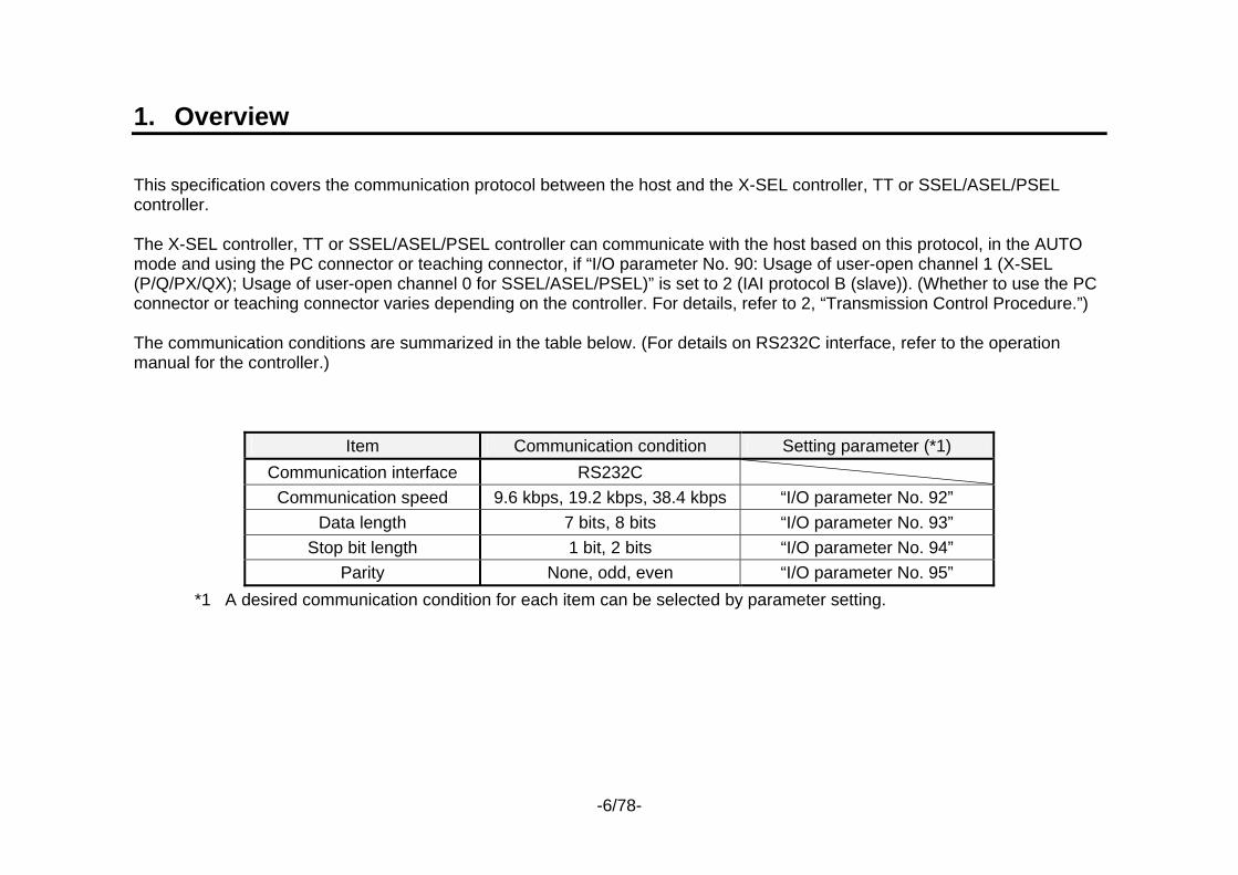
1. Overview This specification covers the communication protocol between the host and the X-SEL controller, TT or SSEL/ASEL/PSEL controller. The X-SEL controller, TT or SSEL/ASEL/PSEL controller can communicate with the host based on this protocol, in the AUTO mode and using the PC connector or teaching connector, if “I/O parameter No. 90: Usage of user-open channel 1 (X-SEL (P/Q/PX/QX); Usage of user-open channel 0 for SSEL/ASEL/PSEL)” is set to 2 (IAI protocol B (slave)). (Whether to use the PC connector or teaching connector varies depending on the controller. For details, refer to 2, “Transmission Control Procedure.”) The communication conditions are summarized in the table below. (For details on RS232C interface, refer to the operation manual for the controller.)
Item Communication condition Setting parameter (*1) Communication interface RS232C
Communication speed 9.6 kbps, 19.2 kbps, 38.4 kbps “I/O parameter No. 92” Data length 7 bits, 8 bits “I/O parameter No. 93”
Stop bit length 1 bit, 2 bits “I/O parameter No. 94” Parity None, odd, even “I/O parameter No. 95”
*1 A desired communication condition for each item can be selected by parameter setting.
-7/78-
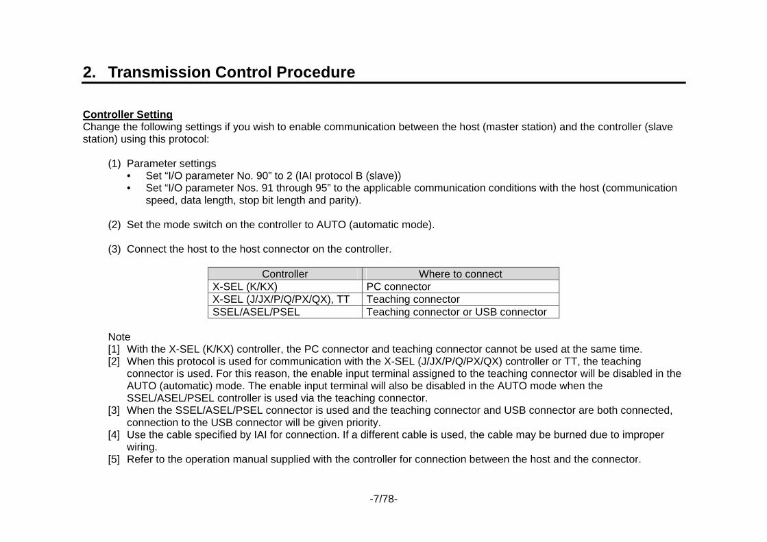
2. Transmission Control Procedure Controller Setting Change the following settings if you wish to enable communication between the host (master station) and the controller (slave station) using this protocol:
(1) Parameter settings • Set “I/O parameter No. 90” to 2 (IAI protocol B (slave)) • Set “I/O parameter Nos. 91 through 95” to the applicable communication conditions with the host (communication
speed, data length, stop bit length and parity). (2) Set the mode switch on the controller to AUTO (automatic mode). (3) Connect the host to the host connector on the controller.
Controller Where to connect X-SEL (K/KX) PC connector X-SEL (J/JX/P/Q/PX/QX), TT Teaching connector SSEL/ASEL/PSEL Teaching connector or USB connector
Note [1] With the X-SEL (K/KX) controller, the PC connector and teaching connector cannot be used at the same time. [2] When this protocol is used for communication with the X-SEL (J/JX/P/Q/PX/QX) controller or TT, the teaching
connector is used. For this reason, the enable input terminal assigned to the teaching connector will be disabled in the AUTO (automatic) mode. The enable input terminal will also be disabled in the AUTO mode when the SSEL/ASEL/PSEL controller is used via the teaching connector.
[3] When the SSEL/ASEL/PSEL connector is used and the teaching connector and USB connector are both connected, connection to the USB connector will be given priority.
[4] Use the cable specified by IAI for connection. If a different cable is used, the cable may be burned due to improper wiring.
[5] Refer to the operation manual supplied with the controller for connection between the host and the connector.

-8/78-
Message Transmission Timing Under the basic transmission control procedure, one unit of transmission consists of command transmission from the master station (host) and response transmission from the receiving slave station (controller). The switching timing of transmission between the master station and slave station conforms to the following rules:
(1) Minimum delay time after completion of command reception by the slave station (controller) before start of response transmission = α msec α is the setting of “I/O parameter No. 97: User-open SIO channel 1, IAI-protocol response minimum delay time (X-SEL (P/Q/PX/QX); User-open SIO channel 0, IAI-protocol response minimum delay time for SSEL/ASEL/PSEL)” (this parameter is available in X-SEL-J/K main application V0.26 or later). The slave station (controller) will start sending a response message when this time has elapsed after completing the reception of a command message. The master station (host) must become reception-ready within this time after completing the transmission of a command message.
(2) Minimum delay time after completion of response reception by the master station (host) before start of command
transmission = 1 msec The slave station (controller) will become reception-ready within this time after completing the transmission of a response message. The master station (host) must start sending the next command message only when this time has elapsed after completing the reception of a response message.
-9/78-
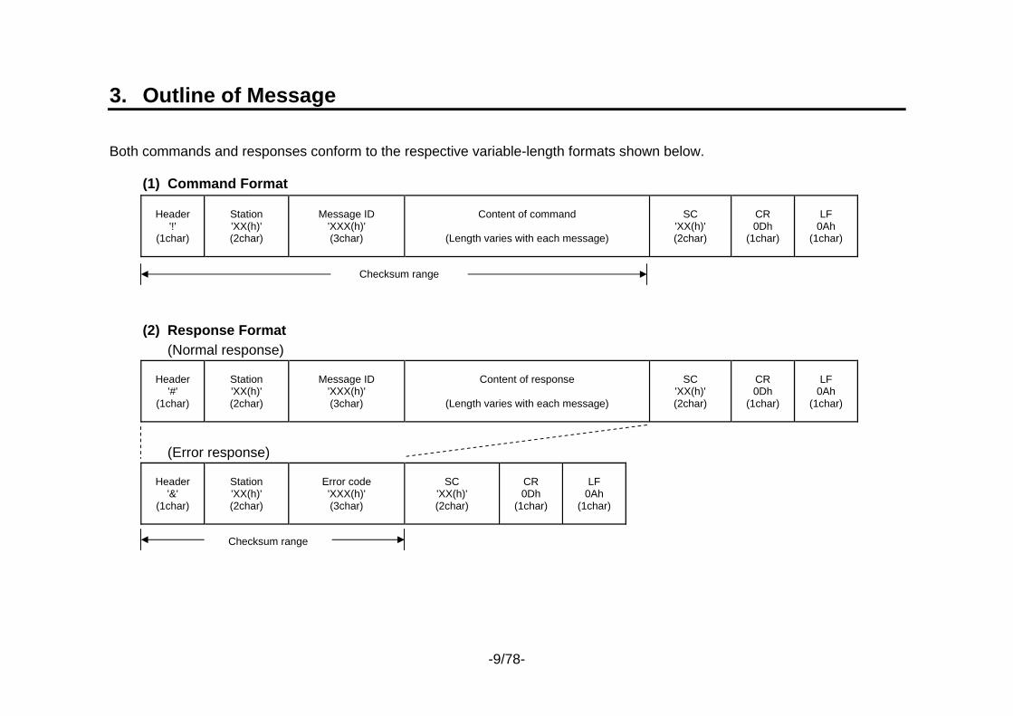
3. Outline of Message Both commands and responses conform to the respective variable-length formats shown below.
(1) Command Format
Header '!'
(1char)
Station 'XX(h)' (2char)
Message ID 'XXX(h)' (3char)
Content of command
(Length varies with each message)
SC 'XX(h)' (2char)
CR 0Dh
(1char)
LF 0Ah
(1char)
(2) Response Format (Normal response)
Header '#'
(1char)
Station 'XX(h)' (2char)
Message ID 'XXX(h)' (3char)
Content of response
(Length varies with each message)
SC 'XX(h)' (2char)
CR 0Dh
(1char)
LF 0Ah
(1char)
(Error response)
Header '&'
(1char)
Station 'XX(h)' (2char)
Error code 'XXX(h)' (3char)
SC 'XX(h)' (2char)
CR 0Dh
(1char)
LF 0Ah
(1char)
Checksum range
Checksum range
-10/78-
Header: Indicate the start of a command/response message. The header specifies one of the following message
categories: ‘!’ (21H) - - - Command ‘#’ (23H) - - - Normal response ‘&’ (26H) - - - Error response
Station: Indicate the station number of the controller (value of “I/O parameter No. 91: User-open SIO channel 1, station code (X-SEL (P/Q/PX/QX); User-open SIO channel 0, station code for SSEL/ASEL/PSEL).
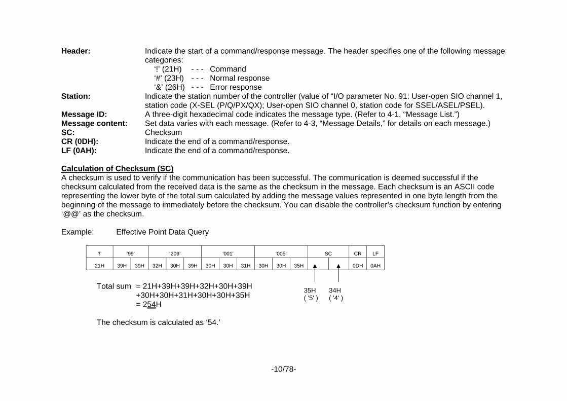
Message ID: A three-digit hexadecimal code indicates the message type. (Refer to 4-1, “Message List.”) Message content: Set data varies with each message. (Refer to 4-3, “Message Details,” for details on each message.) SC: Checksum CR (0DH): Indicate the end of a command/response. LF (0AH): Indicate the end of a command/response. Calculation of Checksum (SC) A checksum is used to verify if the communication has been successful. The communication is deemed successful if the checksum calculated from the received data is the same as the checksum in the message. Each checksum is an ASCII code representing the lower byte of the total sum calculated by adding the message values represented in one byte length from the beginning of the message to immediately before the checksum. You can disable the controller’s checksum function by entering ‘@@’ as the checksum. Example: Effective Point Data Query
Total sum = 21H+39H+39H+32H+30H+39H +30H+30H+31H+30H+30H+35H = 254H
The checksum is calculated as ‘54.’
‘!’ ‘99’ ‘209’ ‘001’ ‘005’ SC CR LF
21H 39H 39H 32H 30H 39H 30H 30H 31H 30H 30H 35H 0DH 0AH
35H ( '5' )
34H ( '4' )

-11/78-
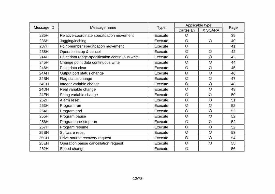
4. Message Details 4-1. Message List
Applicable type Message ID Message name Type Cartesian IX SCARA
Page
Error response Common 15 200H Test call Query 16 201H Version code query Query 17 208H Number of effective point data query Query 18 209H Effective point data query Query 19 20BH Input port query Query 20 20CH Output port query Query 21 20DH Flag query Query 22 20EH Integer variable query Query 23 20FH Real variable query Query 24 210H String variable query Query 26 212H Axis status query Query 27 213H Program status query Query 29 215H System status query Query 30 216H Error detail information query Query 32 21EH Number of effective point data query 2 Query *1 *1 34 21FH Effective point data query 2 Query *1 *1 35 232H Servo ON/OFF Execute 36 233H Home return Execute *2 37 234H Absolute-coordinate specification movement Execute 38
-12/78-
Applicable type Message ID Message name Type
Cartesian IX SCARA Page
235H Relative-coordinate specification movement Execute 39 236H Jogging/inching Execute 40 237H Point-number specification movement Execute 41 238H Operation stop & cancel Execute 42 244H Point data range-specification continuous write Execute 43 245H Change point data continuous write Execute 44 246H Point data clear Execute 45 24AH Output port status change Execute 46 24BH Flag status change Execute 47 24CH Integer variable change Execute 48 24DH Real variable change Execute 49 24EH String variable change Execute 50 252H Alarm reset Execute 51 253H Program run Execute 52 254H Program end Execute 52 255H Program pause Execute 52 256H Program one-step run Execute 52 257H Program resume Execute 52 25BH Software reset Execute 53 25CH Drive-source recovery request Execute 54 25EH Operation pause cancellation request Execute 55 262H Speed change Execute 56

-13/78-
Applicable type Message ID Message name Type
Cartesian IX SCARA Page
26BH Point-number specification movement 2 Execute *1 *1 57 26CH Point data range-specification continuous write 2 Execute *1 *1 58 26DH Change point data continuous write 2 Execute *1 *1 59 26EH Point data clear 2 Execute *1 *1 60 271H Controller function specification 2 Execute *1 *1 61
2A0H Coordinate system definition data range-specification continuous query Query 62
2A1H SCARA axis status query Query 63
2A2H Simple-interference-check-zone definition data range-specification continuous query Query 65
2D4H SCARA absolute-coordinate specification movement Execute 67 2D5H SCARA relative-coordinate specification movement Execute 68 2D6H SCARA point-number specification movement Execute 69 2D9H SCARA point-number specification movement 2 Execute *1 70
*1 Only X-SEL-P/Q main application Version 0.56 or later, PX/QX main application Version 0.26 or later, SSEL main application Version 0.15 or later can be used.
*2 With SCARA axes of X-SEL-JX/KX/PX/QX controllers, this can be used only by IAI as a “Z-axis ABS reset position movement” command. Direct-acting axes of X-SEL-PX/QX controllers can also be used by users.
4-2. Error Response If, for some reason, the slave station (controller) cannot execute the command from the master station (host) that has been received as a normal command by the slave station (controller), an error response will be sent to the master station (host). Each error response stores an error number, so identify the cause of failed command execution based on the error number and take an appropriate action. Refer to 4-3-1, “Error Response,” for details on the error response format.
-14/78-
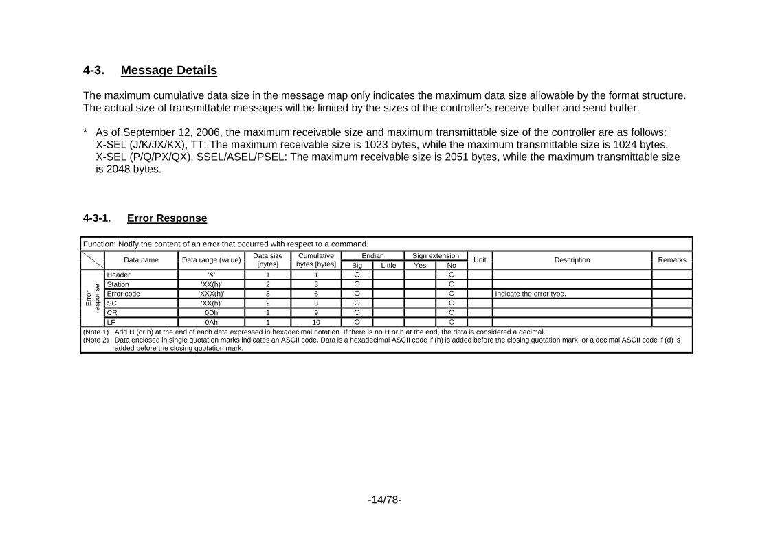
4-3. Message Details The maximum cumulative data size in the message map only indicates the maximum data size allowable by the format structure. The actual size of transmittable messages will be limited by the sizes of the controller’s receive buffer and send buffer. * As of September 12, 2006, the maximum receivable size and maximum transmittable size of the controller are as follows:
X-SEL (J/K/JX/KX), TT: The maximum receivable size is 1023 bytes, while the maximum transmittable size is 1024 bytes. X-SEL (P/Q/PX/QX), SSEL/ASEL/PSEL: The maximum receivable size is 2051 bytes, while the maximum transmittable size is 2048 bytes.
4-3-1. Error Response Function: Notify the content of an error that occurred with respect to a command.
Endian Sign extension Data name Data range (value) Data size [bytes]
Cumulative bytes [bytes] Big Little Yes No
Unit Description Remarks
Header '&' 1 1 Station 'XX(h)' 2 3 Error code 'XXX(h)' 3 6 Indicate the error type. SC 'XX(h)' 2 8 CR 0Dh 1 9
Erro
r re
spon
se
LF 0Ah 1 10 (Note 1) Add H (or h) at the end of each data expressed in hexadecimal notation. If there is no H or h at the end, the data is considered a decimal. (Note 2) Data enclosed in single quotation marks indicates an ASCII code. Data is a hexadecimal ASCII code if (h) is added before the closing quotation mark, or a decimal ASCII code if (d) is
added before the closing quotation mark.
-15/78-
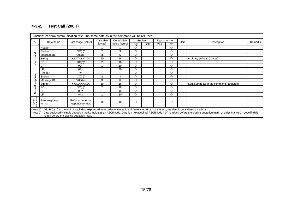
4-3-2. Test Call (200H) Function: Perform communication test. The same data as in the command will be returned.
Endian Sign extension Data name Data range (value) Data size [bytes]
Cumulative bytes [bytes] Big Little Yes No
Unit Description Remarks
Header '!' 1 1 Station 'XX(h)' 2 3 Message ID '200(h)' 3 6 String 'XXXXXXXXXX' 10 16 Arbitrary string (10 bytes) SC 'XX(h)' 2 18 CR 0Dh 1 19
Com
man
d
LF 0Ah 1 20 Header '#' 1 1 Station 'XX(h)' 2 3 Message ID '200(h)' 3 6 String 'XXXXXXXXXX' 10 16 Same string as in the command (10 bytes) SC 'XX(h)' 2 18 CR 0Dh 1 19
Nor
mal
resp
onse
LF 0Ah 1 20
Err
or
resp
onse
Error response format
Refer to the error response format. 10 10
(Note 1) Add H (or h) at the end of each data expressed in hexadecimal notation. If there is no H or h at the end, the data is considered a decimal. (Note 2) Data enclosed in single quotation marks indicates an ASCII code. Data is a hexadecimal ASCII code if (h) is added before the closing quotation mark, or a decimal ASCII code if (d) is
added before the closing quotation mark.
-16/78-
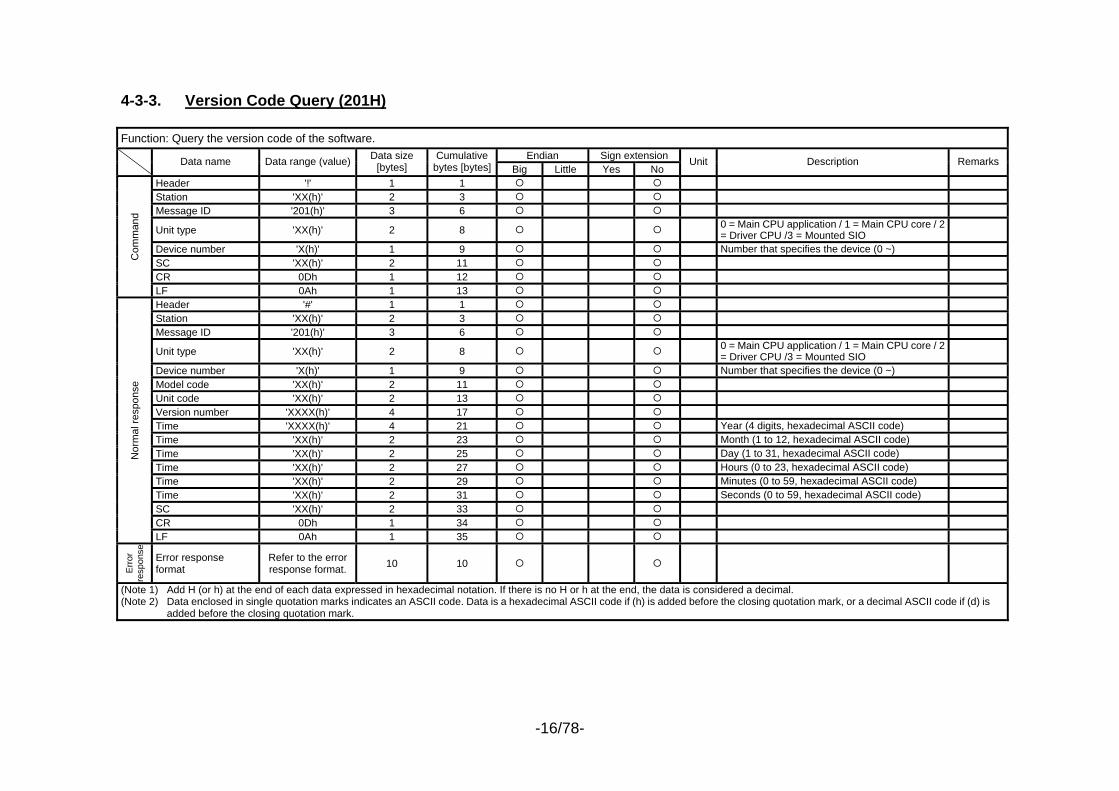
4-3-3. Version Code Query (201H) Function: Query the version code of the software.
Endian Sign extension Data name Data range (value) Data size [bytes]
Cumulative bytes [bytes] Big Little Yes No
Unit Description Remarks
Header '!' 1 1 Station 'XX(h)' 2 3 Message ID '201(h)' 3 6
Unit type 'XX(h)' 2 8 0 = Main CPU application / 1 = Main CPU core / 2 = Driver CPU /3 = Mounted SIO
Device number 'X(h)' 1 9 Number that specifies the device (0 ~) SC 'XX(h)' 2 11 CR 0Dh 1 12
Com
man
d
LF 0Ah 1 13 Header '#' 1 1 Station 'XX(h)' 2 3 Message ID '201(h)' 3 6
Unit type 'XX(h)' 2 8 0 = Main CPU application / 1 = Main CPU core / 2 = Driver CPU /3 = Mounted SIO
Device number 'X(h)' 1 9 Number that specifies the device (0 ~) Model code 'XX(h)' 2 11 Unit code 'XX(h)' 2 13 Version number 'XXXX(h)' 4 17 Time 'XXXX(h)' 4 21 Year (4 digits, hexadecimal ASCII code) Time 'XX(h)' 2 23 Month (1 to 12, hexadecimal ASCII code) Time 'XX(h)' 2 25 Day (1 to 31, hexadecimal ASCII code) Time 'XX(h)' 2 27 Hours (0 to 23, hexadecimal ASCII code) Time 'XX(h)' 2 29 Minutes (0 to 59, hexadecimal ASCII code) Time 'XX(h)' 2 31 Seconds (0 to 59, hexadecimal ASCII code) SC 'XX(h)' 2 33 CR 0Dh 1 34
Nor
mal
resp
onse
LF 0Ah 1 35
Err
or
resp
onse
Error response format
Refer to the error response format. 10 10
(Note 1) Add H (or h) at the end of each data expressed in hexadecimal notation. If there is no H or h at the end, the data is considered a decimal. (Note 2) Data enclosed in single quotation marks indicates an ASCII code. Data is a hexadecimal ASCII code if (h) is added before the closing quotation mark, or a decimal ASCII code if (d) is
added before the closing quotation mark.
-17/78-
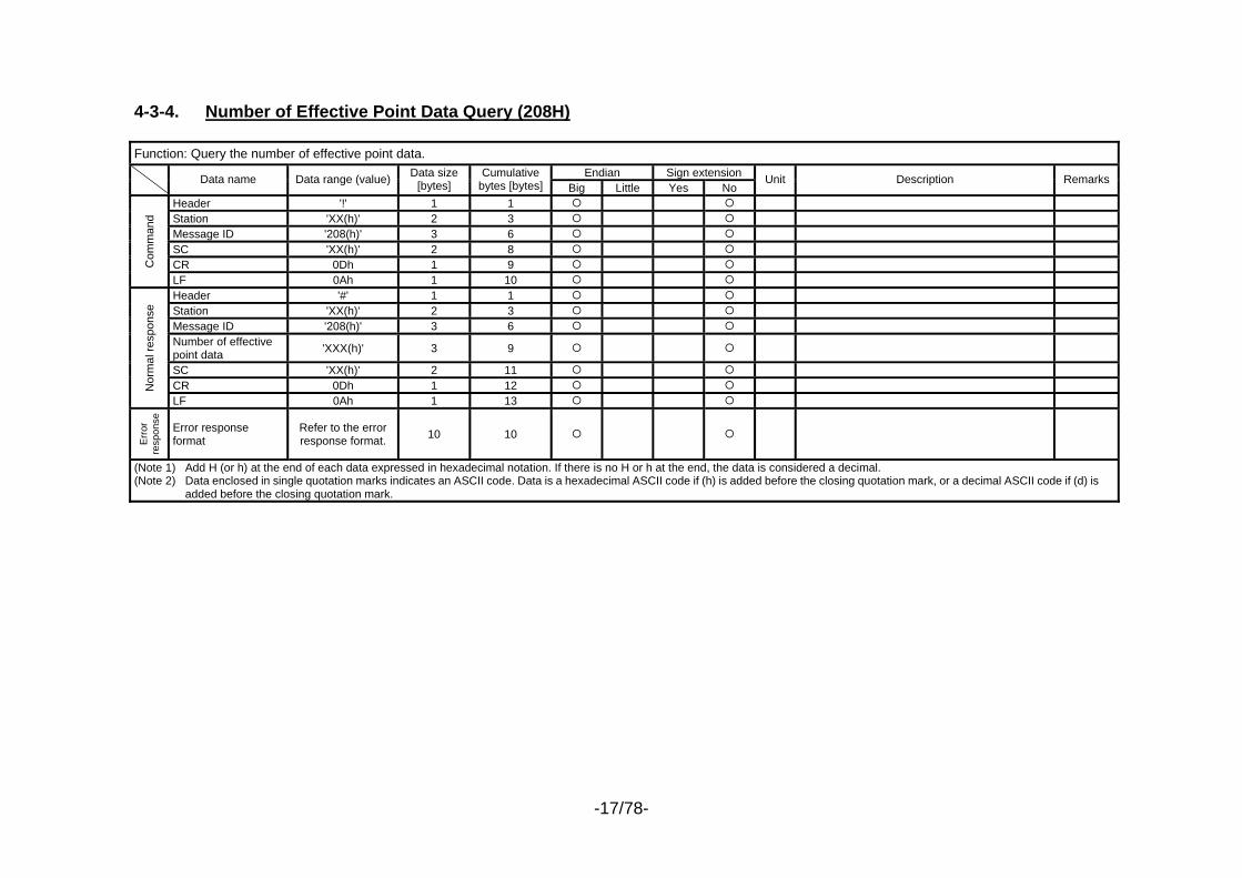
4-3-4. Number of Effective Point Data Query (208H) Function: Query the number of effective point data.
Endian Sign extension Data name Data range (value) Data size [bytes]
Cumulative bytes [bytes] Big Little Yes No
Unit Description Remarks
Header '!' 1 1 Station 'XX(h)' 2 3 Message ID '208(h)' 3 6 SC 'XX(h)' 2 8 CR 0Dh 1 9 C
omm
and
LF 0Ah 1 10 Header '#' 1 1 Station 'XX(h)' 2 3 Message ID '208(h)' 3 6 Number of effective point data 'XXX(h)' 3 9
SC 'XX(h)' 2 11 CR 0Dh 1 12 N
orm
al re
spon
se
LF 0Ah 1 13
Err
or
resp
onse
Error response format
Refer to the error response format. 10 10
(Note 1) Add H (or h) at the end of each data expressed in hexadecimal notation. If there is no H or h at the end, the data is considered a decimal. (Note 2) Data enclosed in single quotation marks indicates an ASCII code. Data is a hexadecimal ASCII code if (h) is added before the closing quotation mark, or a decimal ASCII code if (d) is
added before the closing quotation mark.
-18/78-
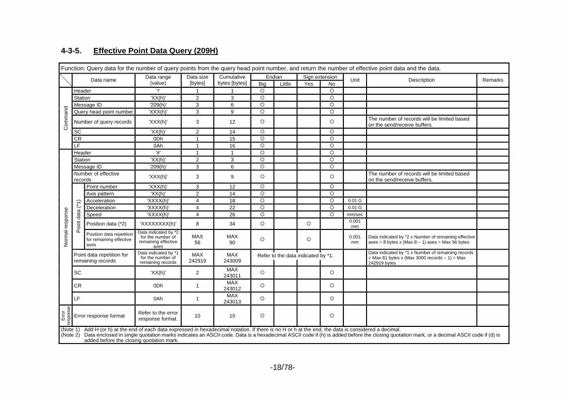
4-3-5. Effective Point Data Query (209H) Function: Query data for the number of query points from the query head point number, and return the number of effective point data and the data.
Endian Sign extension Data name Data range (value)
Data size [bytes]
Cumulative bytes [bytes] Big Little Yes No
Unit Description Remarks
Header '!' 1 1 Station 'XX(h)' 2 3 Message ID '209(h)' 3 6 Query head point number 'XXX(h)' 3 9
Number of query records 'XXX(h)' 3 12 The number of records will be limited based on the send/receive buffers.
SC 'XX(h)' 2 14 CR 0Dh 1 15
Com
man
d
LF 0Ah 1 16 Header '#' 1 1 Station 'XX(h)' 2 3 Message ID '209(h)' 3 6 Number of effective records 'XXX(h)' 3 9 The number of records will be limited based
on the send/receive buffers.
Point number 'XXX(h)' 3 12 Axis pattern 'XX(h)' 2 14 Acceleration 'XXXX(h)' 4 18 0.01 G Deceleration 'XXXX(h)' 4 22 0.01 G Speed 'XXXX(h)' 4 26 mm/sec
Position data (*2) 'XXXXXXXX(h)' 8 34 0.001 mm
Poin
t dat
a (*
1)
Position data repetition for remaining effective axes
Data indicated by *2 for the number of
remaining effective axes
MAX 56
MAX 90 0.001
mm Data indicated by *2 x Number of remaining effective axes = 8 bytes x (Max 8 – 1) axes = Max 56 bytes
Point data repetition for remaining records
Data indicated by *1 for the number of remaining records
MAX 242919
MAX 243009
Data indicated by *1 x Number of remaining records = Max 81 bytes x (Max 3000 records – 1) = Max 242919 bytes
SC 'XX(h)' 2 MAX 243011
CR 0Dh 1 MAX 243012
Nor
mal
resp
onse
LF 0Ah 1 MAX 243013
Err
or
resp
onse
Error response format Refer to the error response format. 10 10
(Note 1) Add H (or h) at the end of each data expressed in hexadecimal notation. If there is no H or h at the end, the data is considered a decimal. (Note 2) Data enclosed in single quotation marks indicates an ASCII code. Data is a hexadecimal ASCII code if (h) is added before the closing quotation mark, or a decimal ASCII code if (d) is
added before the closing quotation mark.
Refer to the data indicated by *1.

-19/78-
4-3-6. Input Port Query (20BH) Function: Query input ports.
Endian Sign extension Data name Data range (value)
Data size [bytes]
Cumulative bytes [bytes] Big Little Yes No
Unit Description Remarks
Header '!' 1 1 Station 'XX(h)' 2 3 Message ID '20B(h)' 3 6 Query start port number 'XXXX(h)' 4 10 Be sure to specify “Category head port
number + Multiple of 8.” Number of query ports 'XXXX(h)' 4 14 The number of ports will be limited based on
the send/receive buffers. SC 'XX(h)' 2 16 CR 0Dh 1 17
Com
man
d
LF 0Ah 1 18 Header '#' 1 1 Station 'XX(h)' 2 3 Message ID '20B(h)' 3 6 Response start port number 'XXXX(h)' 4 10 Number of response ports 'XXXX(h)' 4 14 The number of ports will be limited based on
the send/receive buffers. Input port data (*1) 'XX(h)' 2 16 8 bits from the head input port Remaining input port data
Data indicated by *1 for the number of remaining data
MAX 16382
MAX 16398 Remaining input port data = 2 bytes x (Max
8192 – 1) = 16382 bytes
SC 'XX(h)' 2 MAX 16400
CR 0Dh 1 MAX 16401
Nor
mal
resp
onse
LF 0Ah 1 MAX 16402
Erro
r re
spon
se
Error response format
Refer to the error response format. 10 10
(Note 1) Add H (or h) at the end of each data expressed in hexadecimal notation. If there is no H or h at the end, the data is considered a decimal. (Note 2) Data enclosed in single quotation marks indicates an ASCII code. Data is a hexadecimal ASCII code if (h) is added before the closing quotation mark, or a
decimal ASCII code if (d) is added before the closing quotation mark.
-20/78-
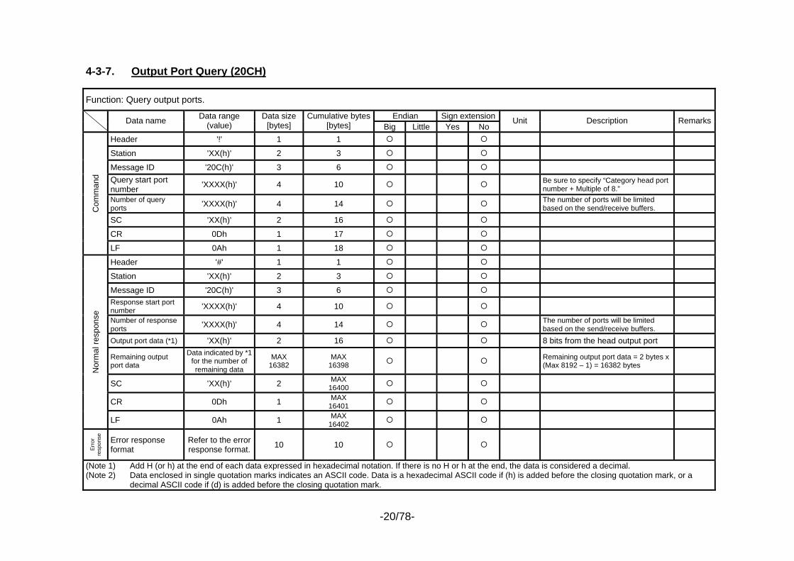
4-3-7. Output Port Query (20CH)
Function: Query output ports.
Endian Sign extension Data name Data range (value)
Data size [bytes]
Cumulative bytes [bytes] Big Little Yes No
Unit Description Remarks
Header '!' 1 1 Station 'XX(h)' 2 3 Message ID '20C(h)' 3 6 Query start port number 'XXXX(h)' 4 10 Be sure to specify “Category head port
number + Multiple of 8.” Number of query ports 'XXXX(h)' 4 14 The number of ports will be limited
based on the send/receive buffers. SC 'XX(h)' 2 16 CR 0Dh 1 17
Com
man
d
LF 0Ah 1 18 Header '#' 1 1 Station 'XX(h)' 2 3 Message ID '20C(h)' 3 6 Response start port number 'XXXX(h)' 4 10 Number of response ports 'XXXX(h)' 4 14 The number of ports will be limited
based on the send/receive buffers. Output port data (*1) 'XX(h)' 2 16 8 bits from the head output port Remaining output port data
Data indicated by *1 for the number of remaining data
MAX 16382
MAX 16398 Remaining output port data = 2 bytes x
(Max 8192 – 1) = 16382 bytes
SC 'XX(h)' 2 MAX 16400
CR 0Dh 1 MAX 16401
Nor
mal
resp
onse
LF 0Ah 1 MAX 16402
Erro
r re
spon
se
Error response format
Refer to the error response format. 10 10
(Note 1) Add H (or h) at the end of each data expressed in hexadecimal notation. If there is no H or h at the end, the data is considered a decimal. (Note 2) Data enclosed in single quotation marks indicates an ASCII code. Data is a hexadecimal ASCII code if (h) is added before the closing quotation mark, or a
decimal ASCII code if (d) is added before the closing quotation mark.
-21/78-
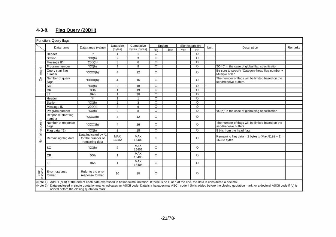
4-3-8. Flag Query (20DH) Function: Query flags.
Endian Sign extension Data name Data range (value) Data size [bytes]
Cumulative bytes [bytes] Big Little Yes No
Unit Description Remarks
Header '!' 1 1 Station 'XX(h)' 2 3 Message ID '20D(h)' 3 6 Program number 'XX(h)' 2 8 ‘00(h)’ in the case of global flag specification Query start flag number 'XXXX(h)' 4 12 Be sure to specify “Category head flag number +
Multiple of 8.”
Number of query flags 'XXXX(h)' 4 16 The number of flags will be limited based on the
send/receive buffers.
SC 'XX(h)' 2 18 CR 0Dh 1 19
Com
man
d
LF 0Ah 1 20 Header '#' 1 1 Station 'XX(h)' 2 3 Message ID '20D(h)' 3 6 Program number 'XX(h)' 2 8 ‘00(h)’ in the case of global flag specification Response start flag number 'XXXX(h)' 4 12
Number of response flags 'XXXX(h)' 4 16 The number of flags will be limited based on the
send/receive buffers.
Flag data (*1) 'XX(h)' 2 18 8 bits from the head flag.
Remaining flag data Data indicated by *1
for the number of remaining data
MAX 16382
MAX 16400 Remaining flag data = 2 bytes x (Max 8192 – 1) =
16382 bytes
SC 'XX(h)' 2 MAX 16402
CR 0Dh 1 MAX 16403
Nor
mal
resp
onse
LF 0Ah 1 MAX 16404
Erro
r re
spon
se
Error response format
Refer to the error response format. 10 10
(Note 1) Add H (or h) at the end of each data expressed in hexadecimal notation. If there is no H or h at the end, the data is considered a decimal. (Note 2) Data enclosed in single quotation marks indicates an ASCII code. Data is a hexadecimal ASCII code if (h) is added before the closing quotation mark, or a decimal ASCII code if (d) is
added before the closing quotation mark.
-22/78-
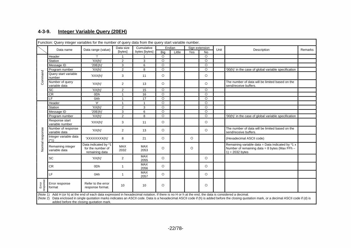
4-3-9. Integer Variable Query (20EH) Function: Query integer variables for the number of query data from the query start variable number.
Endian Sign extension Data name Data range (value) Data size [bytes]
Cumulative bytes [bytes] Big Little Yes No
Unit Description Remarks
Header '!' 1 1 Station 'XX(h)' 2 3 Message ID '20E(h)' 3 6 Program number 'XX(h)' 2 8 ‘00(h)’ in the case of global variable specification Query start variable number 'XXX(h)' 3 11
Number of query variable data 'XX(h)' 2 13 The number of data will be limited based on the
send/receive buffers.
SC 'XX(h)' 2 15 CR 0Dh 1 16
Com
man
d
LF 0Ah 1 17 Header '#' 1 1 Station 'XX(h)' 2 3 Message ID '20E(h)' 3 6 Program number 'XX(h)' 2 8 ‘00(h)’ in the case of global variable specification Response start variable number 'XXX(h)' 3 11
Number of response variable data 'XX(h)' 2 13 The number of data will be limited based on the
send/receive buffers.
Integer variable data (*1) 'XXXXXXXX(h)' 8 21 (Hexadecimal ASCII code)
Remaining integer variable data
Data indicated by *1 for the number of remaining data
MAX 2032
MAX 2053
Remaining variable data = Data indicated by *1 x Number of remaining data = 8 bytes (Max FFh – 1) = 2032 bytes
SC 'XX(h)' 2 MAX 2055
CR 0Dh 1 MAX 2056
Nor
mal
resp
onse
LF 0Ah 1 MAX 2057
Err
or
resp
onse
Error response format
Refer to the error response format. 10 10
(Note 1) Add H (or h) at the end of each data expressed in hexadecimal notation. If there is no H or h at the end, the data is considered a decimal. (Note 2) Data enclosed in single quotation marks indicates an ASCII code. Data is a hexadecimal ASCII code if (h) is added before the closing quotation mark, or a decimal ASCII code if (d) is
added before the closing quotation mark.
-23/78-
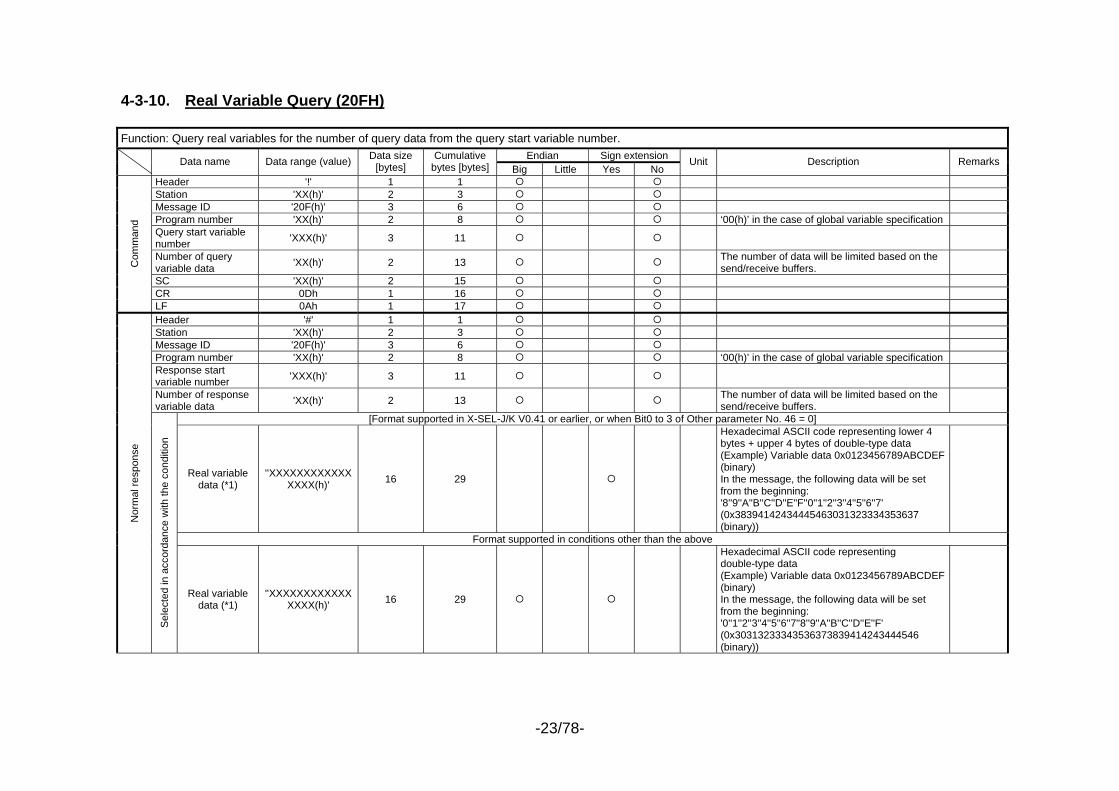
4-3-10. Real Variable Query (20FH) Function: Query real variables for the number of query data from the query start variable number.
Endian Sign extension Data name Data range (value) Data size [bytes]
Cumulative bytes [bytes] Big Little Yes No
Unit Description Remarks
Header '!' 1 1 Station 'XX(h)' 2 3 Message ID '20F(h)' 3 6 Program number 'XX(h)' 2 8 ‘00(h)’ in the case of global variable specification Query start variable number 'XXX(h)' 3 11
Number of query variable data 'XX(h)' 2 13 The number of data will be limited based on the
send/receive buffers.
SC 'XX(h)' 2 15 CR 0Dh 1 16
Com
man
d
LF 0Ah 1 17 Header '#' 1 1 Station 'XX(h)' 2 3 Message ID '20F(h)' 3 6 Program number 'XX(h)' 2 8 ‘00(h)’ in the case of global variable specification Response start variable number 'XXX(h)' 3 11
Number of response variable data 'XX(h)' 2 13 The number of data will be limited based on the
send/receive buffers.
[Format supported in X-SEL-J/K V0.41 or earlier, or when Bit0 to 3 of Other parameter No. 46 = 0]
Real variable data (*1)
''XXXXXXXXXXXXXXXX(h)' 16 29
Hexadecimal ASCII code representing lower 4 bytes + upper 4 bytes of double-type data (Example) Variable data 0x0123456789ABCDEF (binary) In the message, the following data will be set from the beginning: '8''9''A''B''C''D''E''F''0''1''2''3''4''5''6''7' (0x38394142434445463031323334353637 (binary))
Format supported in conditions other than the above
Nor
mal
resp
onse
Sel
ecte
d in
acc
orda
nce
with
the
cond
ition
Real variable data (*1)
''XXXXXXXXXXXXXXXX(h)' 16 29
Hexadecimal ASCII code representing double-type data (Example) Variable data 0x0123456789ABCDEF (binary) In the message, the following data will be set from the beginning: '0''1''2''3''4''5''6''7''8''9''A''B''C''D''E''F' (0x30313233343536373839414243444546 (binary))
-24/78-
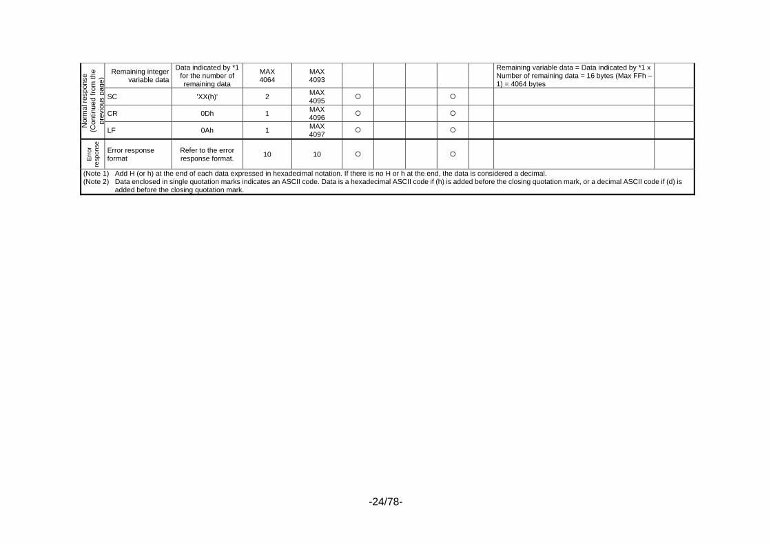
Remaining integer
variable data
Data indicated by *1 for the number of remaining data
MAX 4064
MAX 4093
Remaining variable data = Data indicated by *1 x Number of remaining data = 16 bytes (Max FFh – 1) = 4064 bytes
SC 'XX(h)' 2 MAX 4095
CR 0Dh 1 MAX 4096
Nor
mal
resp
onse
(C
ontin
ued
from
the
prev
ious
pag
e)
LF 0Ah 1 MAX 4097
Err
or
resp
onse
Error response format
Refer to the error response format. 10 10
(Note 1) Add H (or h) at the end of each data expressed in hexadecimal notation. If there is no H or h at the end, the data is considered a decimal. (Note 2) Data enclosed in single quotation marks indicates an ASCII code. Data is a hexadecimal ASCII code if (h) is added before the closing quotation mark, or a decimal ASCII code if (d) is
added before the closing quotation mark.
-25/78-
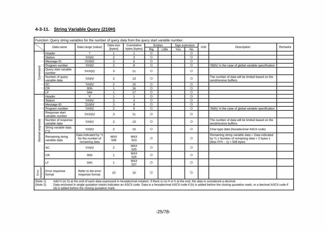
4-3-11. String Variable Query (210H) Function: Query string variables for the number of query data from the query start variable number.
Endian Sign extension Data name Data range (value) Data size [bytes]
Cumulative bytes [bytes] Big Little Yes No
Unit Description Remarks
Header '!' 1 1 Station 'XX(h)' 2 3 Message ID '210(h)' 3 6 Program number 'XX(h)' 2 8 ‘00(h)’ in the case of global variable specification Query start variable number 'XXX(h)' 3 11
Number of query variable data 'XX(h)' 2 13 The number of data will be limited based on the
send/receive buffers.
SC 'XX(h)' 2 15 CR 0Dh 1 16
Com
man
d
LF 0Ah 1 17 Header '#' 1 1 Station 'XX(h)' 2 3 Message ID '210(h)' 3 6 Program number 'XX(h)' 2 8 ‘00(h)’ in the case of global variable specification Response start variable number 'XXX(h)' 3 11
Number of response variable data 'XX(h)' 2 13 The number of data will be limited based on the
send/receive buffers.
String variable data (*1) 'XX(h)' 2 15 Char-type data (hexadecimal ASCII code)
Remaining string variable data
Data indicated by *1 for the number of remaining data
MAX 508
MAX 523
Remaining string variable data = Data indicated by *1 x Number of remaining data = 2 bytes x (Max FFh – 1) = 508 bytes
SC 'XX(h)' 2 MAX 525
CR 0Dh 1 MAX 526
Nor
mal
resp
onse
LF 0Ah 1 MAX 527
Err
or
resp
onse
Error response format
Refer to the error response format. 10 10
(Note 1) Add H (or h) at the end of each data expressed in hexadecimal notation. If there is no H or h at the end, the data is considered a decimal. (Note 2) Data enclosed in single quotation marks indicates an ASCII code. Data is a hexadecimal ASCII code if (h) is added before the closing quotation mark, or a decimal ASCII code if
(d) is added before the closing quotation mark.
-26/78-
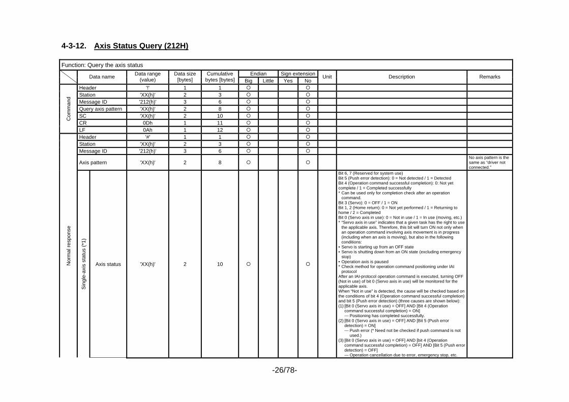
4-3-12. Axis Status Query (212H) Function: Query the axis status
Endian Sign extension Data name Data range (value)
Data size [bytes]
Cumulative bytes [bytes] Big Little Yes No
Unit Description Remarks
Header '!' 1 1 Station 'XX(h)' 2 3 Message ID '212(h)' 3 6 Query axis pattern 'XX(h)' 2 8 SC 'XX(h)' 2 10 CR 0Dh 1 11
Com
man
d
LF 0Ah 1 12 Header '#' 1 1 Station 'XX(h)' 2 3 Message ID '212(h)' 3 6
Axis pattern 'XX(h)' 2 8 No axis pattern is the same as “driver not connected.”
Nor
mal
resp
onse
Sing
le-a
xis
stat
us (*
1)
Axis status 'XX(h)' 2 10
Bit 6, 7 (Reserved for system use) Bit 5 (Push error detection): 0 = Not detected / 1 = Detected Bit 4 (Operation command successful completion): 0: Not yet complete / 1 = Completed successfully * Can be used only for completion check after an operation
command. Bit 3 (Servo): 0 = OFF / 1 = ON Bit 1, 2 (Home return): 0 = Not yet performed / 1 = Returning to home / 2 = Completed Bit 0 (Servo axis in use): 0 = Not in use / 1 = In use (moving, etc.) * “Servo axis in use” indicates that a given task has the right to use
the applicable axis. Therefore, this bit will turn ON not only when an operation command involving axis movement is in progress (including when an axis is moving), but also in the following conditions:
• Servo is starting up from an OFF state • Servo is shutting down from an ON state (excluding emergency
stop) • Operation axis is paused * Check method for operation command positioning under IAI
protocol After an IAI-protocol operation command is executed, turning OFF (Not in use) of bit 0 (Servo axis in use) will be monitored for the applicable axis. When “Not in use” is detected, the cause will be checked based on the conditions of bit 4 (Operation command successful completion) and bit 5 (Push error detection) (three causes are shown below): (1) [Bit 0 (Servo axis in use) = OFF] AND [Bit 4 (Operation
command successful completion) = ON] --- Positioning has completed successfully. (2) [Bit 0 (Servo axis in use) = OFF] AND [Bit 5 (Push error
detection) = ON] --- Push error (* Need not be checked if push command is not
used.) (3) [Bit 0 (Servo axis in use) = OFF] AND [bit 4 (Operation
command successful completion) = OFF] AND [Bit 5 (Push error detection) = OFF]
--- Operation cancellation due to error, emergency stop, etc.
-27/78-
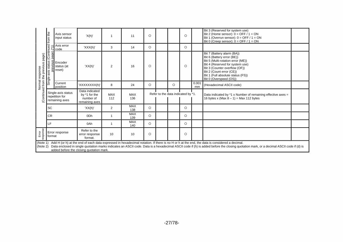
Axis sensor input status 'X(h)' 1 11
Bit 3 (Reserved for system use) Bit 2 (Home sensor): 0 = OFF / 1 = ON Bit 1 (Overrun sensor): 0 = OFF / 1 = ON Bit 0 (Creep sensor): 0 = OFF / 1 = ON
Axis error code 'XXX(h)' 3 14
Encoder status (at reset)
'XX(h)' 2 16
Bit 7 (Battery alarm (BA)) Bit 6 (Battery error (BE)) Bit 5 (Multi-rotation error (ME)) Bit 4 (Reserved for system use) Bit 3 (Counter overflow (OF)) Bit 2 (Count error (CE)) Bit 1 (Full absolute status (FS)) Bit 0 (Overspeed (OS))
Sing
le-a
xis
stat
us (C
ontin
ued
from
the
prev
ious
pag
e) (*
1)
Current position 'XXXXXXXX(h)' 8 24 0.001
mm (Hexadecimal ASCII code)
Single-axis status repetition for remaining axes
Data indicated by *1 for the number of
remaining axes
MAX 112
MAX 136
Data indicated by *1 x Number of remaining effective axes = 16 bytes x (Max 8 – 1) = Max 112 bytes
SC 'XX(h)' 2 MAX 138
CR 0Dh 1 MAX 139
Nor
mal
resp
onse
(C
ontin
ued
from
the
prev
ious
pag
e)
LF 0Ah 1 MAX 140
Erro
r re
spon
se
Error response format
Refer to the error response
format. 10 10
(Note 1) Add H (or h) at the end of each data expressed in hexadecimal notation. If there is no H or h at the end, the data is considered a decimal. (Note 2) Data enclosed in single quotation marks indicates an ASCII code. Data is a hexadecimal ASCII code if (h) is added before the closing quotation mark, or a decimal ASCII code if (d) is
added before the closing quotation mark.
Refer to the data indicated by *1.
-28/78-
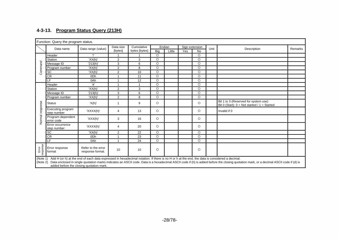
4-3-13. Program Status Query (213H) Function: Query the program status.
Endian Sign extension Data name Data range (value) Data size [bytes]
Cumulative bytes [bytes] Big Little Yes No
Unit Description Remarks
Header '!' 1 1 Station 'XX(h)' 2 3 Message ID '213(h)' 3 6 Program number 'XX(h)' 2 8 SC 'XX(h)' 2 10 CR 0Dh 1 11
Com
man
d
LF 0Ah 1 12 Header '#' 1 1 Station 'XX(h)' 2 3 Message ID '213(h)' 3 6 Program number 'XX(h)' 2 8
Status 'X(h)' 1 9 Bit 1 to 3 (Reserved for system use) Bit 0 (Start): 0 = Not started / 1 = Started
Executing program step number 'XXXX(h)' 4 13 Invalid if 0
Program-dependent error code 'XXX(h)' 3 16
Error occurrence step number 'XXXX(h)' 4 20
SC 'XX(h)' 2 22 CR 0Dh 1 23
Nor
mal
resp
onse
LF 0Ah 1 24
Err
or
resp
onse
Error response format
Refer to the error response format. 10 10
(Note 1) Add H (or h) at the end of each data expressed in hexadecimal notation. If there is no H or h at the end, the data is considered a decimal. (Note 2) Data enclosed in single quotation marks indicates an ASCII code. Data is a hexadecimal ASCII code if (h) is added before the closing quotation mark, or a decimal ASCII code if (d) is
added before the closing quotation mark.
-29/78-
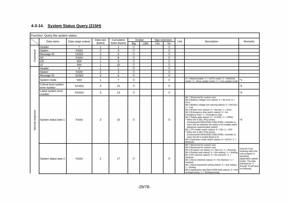
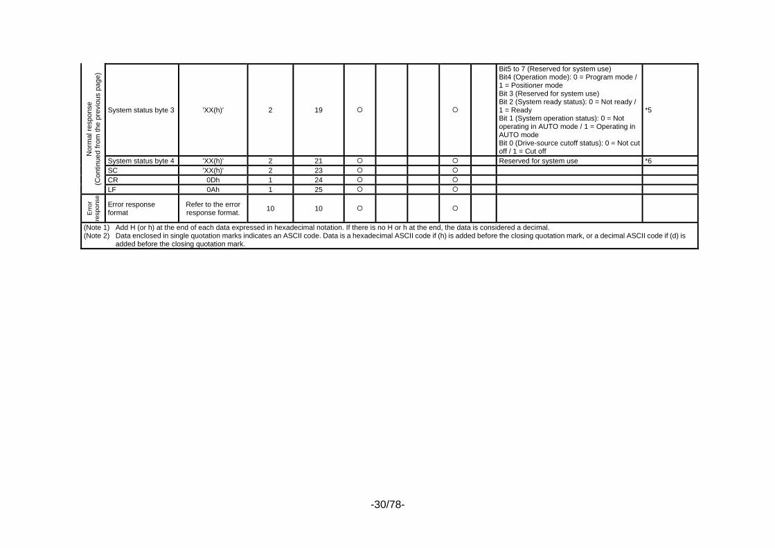
4-3-14. System Status Query (215H) Function: Query the system status.
Endian Sign extension Data name Data range (value) Data size [bytes]
Cumulative bytes [bytes] Big Little Yes No
Unit Description Remarks
Header '!' 1 1 Station 'XX(h)' 2 3 Message ID '215(h)' 3 6 SC 'XX(h)' 2 8 CR 0Dh 1 9 C
omm
and
LF 0Ah 1 10 Header '#' 1 1 Station 'XX(h)' 2 3 Message ID '215(h)' 3 6
System mode 'X(h)' 1 7 0 = Indeterminable / 1 = AUTO mode / 2 = MANUAL mode / 3 = Slave update mode / 4 = Core update mode *1
Critical level system error number 'XXX(h)' 3 10 *2
Latest system error number 'XXX(h)' 3 13 *3
System status byte 1 'XX(h)' 2 15
Bit 7 (Reserved for system use) Bit 6 (Battery voltage error status): 0 = No error /1 = Error Bit 5 (Battery voltage low warning status): 0 = Not low / 1 = Low Bit 4 (Power error status): 0 = Normal / 1 = Error Bit 3 (Emergency stop switch status): 0 = No emergency stop / 1 = Emergency stop Bit 2 (Safety gate status): 0 = CLOSE / 1 = OPEN * When the X-SEL (P/Q series)
(Cartesian/SCARA)/SSEL/ASEL/PSEL controller is used, this bit indicates the status of an enable switch (deadman switch/enable switch).
Bit 1 (TP enable switch status): 0 = ON / 1 = OFF * When the X-SEL (P/Q series)
(Cartesian/SCARA)/SSEL/ASEL/PSEL controller is used, this bit is invalid (fixed to 0).
Bit 0 (Operation mode switch status): 0 = AUTO / 1 = MANUAL
*4
Nor
mal
resp
onse
System status byte 2 'XX(h)' 2 17
Bit 7 (Reserved for system use) Bit 6 (Reserved for system use) Bit 5 (Program run status): 0 = Not run / 1 = Running Bit 4 (Restart wait status): 0 = Not waiting / 1 = WaitingBit 3 (I/O interlock status): 0 = No interlock / 1 = Interlock Bit 2 (Servo interlock status): 0 = No interlock / 1 = Interlock Bit 1 (Slave parameter writing status): 0 = Not writing / 1 = Writing Bit 0 (Application data flash ROM write status): 0 = Not writing/erasing / 1 = Writing/erasing
Only bit 0 has meaning when the core program is operating (application update mode). The data indicated by *1 through *6 will have no meaning.
-30/78-
System status byte 3 'XX(h)' 2 19
Bit5 to 7 (Reserved for system use) Bit4 (Operation mode): 0 = Program mode / 1 = Positioner mode Bit 3 (Reserved for system use) Bit 2 (System ready status): 0 = Not ready / 1 = Ready Bit 1 (System operation status): 0 = Not operating in AUTO mode / 1 = Operating in AUTO mode Bit 0 (Drive-source cutoff status): 0 = Not cut off / 1 = Cut off
*5
System status byte 4 'XX(h)' 2 21 Reserved for system use *6 SC 'XX(h)' 2 23 CR 0Dh 1 24
Nor
mal
resp
onse
(C
ontin
ued
from
the
prev
ious
pag
e)
LF 0Ah 1 25
Err
or
resp
onse
Error response format
Refer to the error response format. 10 10
(Note 1) Add H (or h) at the end of each data expressed in hexadecimal notation. If there is no H or h at the end, the data is considered a decimal. (Note 2) Data enclosed in single quotation marks indicates an ASCII code. Data is a hexadecimal ASCII code if (h) is added before the closing quotation mark, or a decimal ASCII code if (d) is
added before the closing quotation mark.
-31/78-
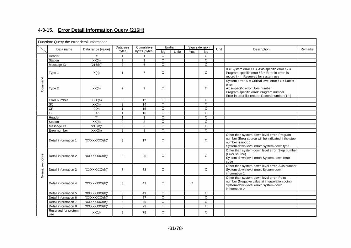
4-3-15. Error Detail Information Query (216H) Function: Query the error detail information.
Endian Sign extension Data name Data range (value) Data size [bytes]
Cumulative bytes [bytes] Big Little Yes No
Unit Description Remarks
Header '!' 1 1 Station 'XX(h)' 2 3 Message ID '216(h)' 3 6
Type 1 'X(h)' 1 7 0 = System error / 1 = Axis-specific error / 2 = Program-specific error / 3 = Error in error list record / 4 = Reserved for system use
Type 2 'XX(h)' 2 9
System error: 0 = Critical level error / 1 = Latest error Axis-specific error: Axis number Program-specific error: Program number Error in error list record: Record number (1 ~)
Error number 'XXX(h)' 3 12 SC 'XX(h)' 2 14 CR 0Dh 1 15
Com
man
d
LF 0Ah 1 16 Header '#' 1 1 Station 'XX(h)' 2 3 Message ID '216(h)' 3 6 Error number 'XXX(h)' 3 9
Detail information 1 'XXXXXXXX(h)' 8 17
Other than system-down level error: Program number (Error source will be indicated if the step number is not 0.) System-down level error: System down type
Detail information 2 'XXXXXXXX(h)' 8 25
Other than system-down level error: Step number (Error source) System-down level error: System down error code
Detail information 3 'XXXXXXXX(h)' 8 33 Other than system-down level error: Axis numberSystem-down level error: System down information 1
Detail information 4 'XXXXXXXX(h)' 8 41
Other than system-down level error: Point number (Negative value at interpolation point) System-down level error: System down information 2
Detail information 5 'XXXXXXXX(h)' 8 49 Detail information 6 'XXXXXXXX(h)' 8 57 Detail information 7 'XXXXXXXX(h)' 8 65 Detail information 8 'XXXXXXXX(h)' 8 73
Nor
mal
resp
onse
Reserved for system use 'XX(d)' 2 75
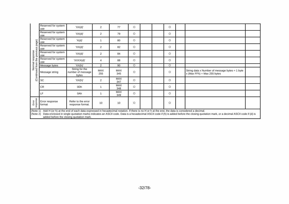
-32/78-
Reserved for system use 'XX(d)' 2 77
Reserved for system use 'XX(d)' 2 79
Reserved for system use 'X(d)' 1 80
Reserved for system use 'XX(d)' 2 82
Reserved for system use 'XX(d)' 2 84
Reserved for system use 'XXXX(d)' 4 88
Message bytes 'XX(h)' 2 90
Message string String for the
number of message bytes
MAX 255
MAX 345 String data x Number of message bytes = 1 byte
x (Max FFh) = Max 255 bytes
SC 'XX(h)' 2 MAX 347
CR 0Dh 1 MAX 348
Nor
mal
resp
onse
(C
ontin
ued
from
the
prev
ious
pag
e)
LF 0Ah 1 MAX 349
Err
or
resp
onse
Error response format
Refer to the error response format. 10 10
(Note 1) Add H (or h) at the end of each data expressed in hexadecimal notation. If there is no H or h at the end, the data is considered a decimal. (Note 2) Data enclosed in single quotation marks indicates an ASCII code. Data is a hexadecimal ASCII code if (h) is added before the closing quotation mark, or a decimal ASCII code if (d) is
added before the closing quotation mark.
-33/78-
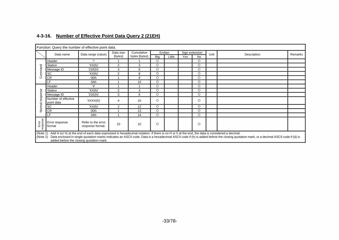
4-3-16. Number of Effective Point Data Query 2 (21EH) Function: Query the number of effective point data.
Endian Sign extension Data name Data range (value) Data size [bytes]
Cumulative bytes [bytes] Big Little Yes No
Unit Description Remarks
Header '!' 1 1 Station 'XX(h)' 2 3 Message ID '21E(h)' 3 6 SC 'XX(h)' 2 8 CR 0Dh 1 9 C
omm
and
LF 0Ah 1 10 Header '#' 1 1 Station 'XX(h)' 2 3 Message ID '21E(h)' 3 6 Number of effective point data 'XXXX(h)' 4 10
SC 'XX(h)' 2 12 CR 0Dh 1 13 N
orm
al re
spon
se
LF 0Ah 1 14
Err
or
resp
onse
Error response format
Refer to the error response format. 10 10
(Note 1) Add H (or h) at the end of each data expressed in hexadecimal notation. If there is no H or h at the end, the data is considered a decimal. (Note 2) Data enclosed in single quotation marks indicates an ASCII code. Data is a hexadecimal ASCII code if (h) is added before the closing quotation mark, or a decimal ASCII code if (d) is
added before the closing quotation mark.
-34/78-
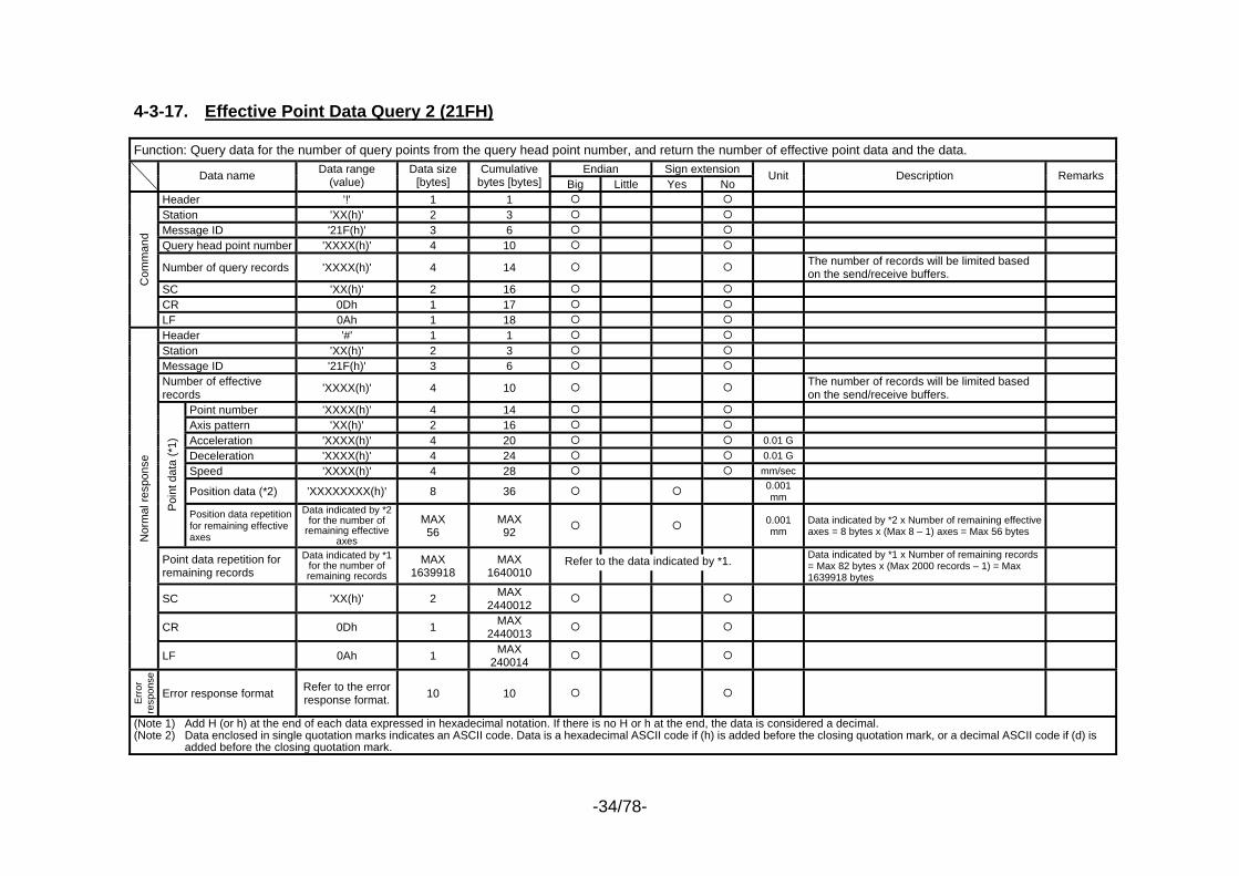
4-3-17. Effective Point Data Query 2 (21FH) Function: Query data for the number of query points from the query head point number, and return the number of effective point data and the data.
Endian Sign extension Data name Data range (value)
Data size [bytes]
Cumulative bytes [bytes] Big Little Yes No
Unit Description Remarks
Header '!' 1 1 Station 'XX(h)' 2 3 Message ID '21F(h)' 3 6 Query head point number 'XXXX(h)' 4 10
Number of query records 'XXXX(h)' 4 14 The number of records will be limited based on the send/receive buffers.
SC 'XX(h)' 2 16 CR 0Dh 1 17
Com
man
d
LF 0Ah 1 18 Header '#' 1 1 Station 'XX(h)' 2 3 Message ID '21F(h)' 3 6 Number of effective records 'XXXX(h)' 4 10 The number of records will be limited based
on the send/receive buffers.
Point number 'XXXX(h)' 4 14 Axis pattern 'XX(h)' 2 16 Acceleration 'XXXX(h)' 4 20 0.01 G Deceleration 'XXXX(h)' 4 24 0.01 G Speed 'XXXX(h)' 4 28 mm/sec
Position data (*2) 'XXXXXXXX(h)' 8 36 0.001 mm
Poin
t dat
a (*
1)
Position data repetition for remaining effective axes
Data indicated by *2 for the number of
remaining effective axes
MAX 56
MAX 92 0.001
mm Data indicated by *2 x Number of remaining effective axes = 8 bytes x (Max 8 – 1) axes = Max 56 bytes
Point data repetition for remaining records
Data indicated by *1 for the number of remaining records
MAX 1639918
MAX 1640010
Data indicated by *1 x Number of remaining records = Max 82 bytes x (Max 2000 records – 1) = Max 1639918 bytes
SC 'XX(h)' 2 MAX 2440012
CR 0Dh 1 MAX 2440013
Nor
mal
resp
onse
LF 0Ah 1 MAX 240014
Err
or
resp
onse
Error response format Refer to the error response format. 10 10
(Note 1) Add H (or h) at the end of each data expressed in hexadecimal notation. If there is no H or h at the end, the data is considered a decimal. (Note 2) Data enclosed in single quotation marks indicates an ASCII code. Data is a hexadecimal ASCII code if (h) is added before the closing quotation mark, or a decimal ASCII code if (d) is
added before the closing quotation mark.
Refer to the data indicated by *1.
-35/78-
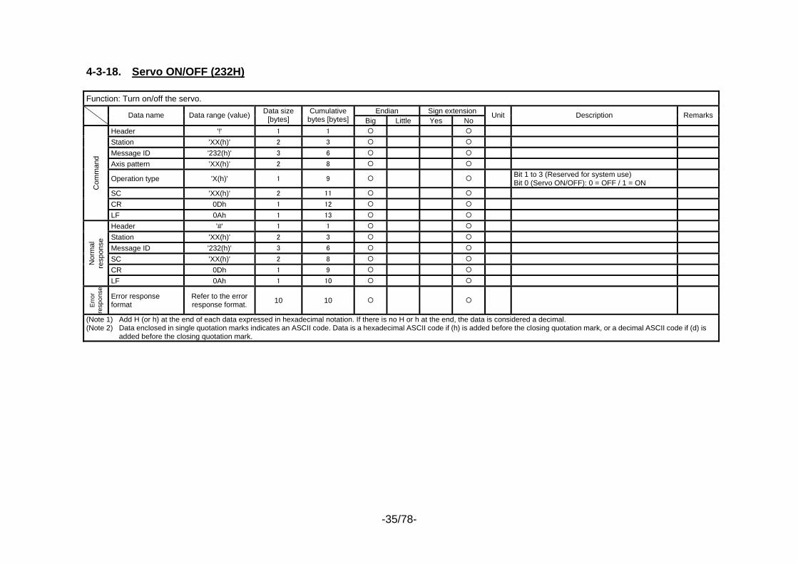
4-3-18. Servo ON/OFF (232H) Function: Turn on/off the servo.
Endian Sign extension Data name Data range (value) Data size [bytes]
Cumulative bytes [bytes] Big Little Yes No
Unit Description Remarks
Header '!' 1 1 Station 'XX(h)' 2 3 Message ID '232(h)' 3 6 Axis pattern 'XX(h)' 2 8
Operation type 'X(h)' 1 9 Bit 1 to 3 (Reserved for system use) Bit 0 (Servo ON/OFF): 0 = OFF / 1 = ON
SC 'XX(h)' 2 11 CR 0Dh 1 12
Com
man
d
LF 0Ah 1 13 Header '#' 1 1 Station 'XX(h)' 2 3 Message ID '232(h)' 3 6 SC 'XX(h)' 2 8 CR 0Dh 1 9
Nor
mal
re
spon
se
LF 0Ah 1 10
Erro
r re
spon
se
Error response format
Refer to the error response format. 10 10
(Note 1) Add H (or h) at the end of each data expressed in hexadecimal notation. If there is no H or h at the end, the data is considered a decimal. (Note 2) Data enclosed in single quotation marks indicates an ASCII code. Data is a hexadecimal ASCII code if (h) is added before the closing quotation mark, or a decimal ASCII code if (d) is
added before the closing quotation mark.
-36/78-
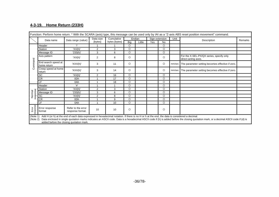
4-3-19. Home Return (233H) Function: Perform home return. * With the SCARA (axis) type, this message can be used only by IAI as a “Z-axis ABS reset position movement” command.
Endian Sign extension Unit Data name Data range (value) Data size [bytes]
Cumulative bytes [bytes] Big Little Yes No
Description Remarks
Header '!' 1 1 Station 'XX(h)' 2 3 Message ID '233(h)' 3 6 Axis pattern 'XX(h)' 2 8 For the X-SEL-PX/QX series, specify only
direct-acting axes.
End search speed at home return 'XXX(h)' 3 11 mm/sec The parameter setting becomes effective if zero.
Creep speed at home return 'XXX(h)' 3 14 mm/sec The parameter setting becomes effective if zero.
SC 'XX(h)' 2 16 CR 0Dh 1 17
Com
man
d
LF 0Ah 1 18 Header '#' 1 1 Station 'XX(h)' 2 3 Message ID '233(h)' 3 6 SC 'XX(h)' 2 8 CR 0Dh 1 9
Nor
mal
re
spon
se
LF 0Ah 1 10
Err
or
resp
onse
Error response format
Refer to the error response format. 10 10
(Note 1) Add H (or h) at the end of each data expressed in hexadecimal notation. If there is no H or h at the end, the data is considered a decimal. (Note 2) Data enclosed in single quotation marks indicates an ASCII code. Data is a hexadecimal ASCII code if (h) is added before the closing quotation mark, or a decimal ASCII code if (d) is
added before the closing quotation mark.
-37/78-
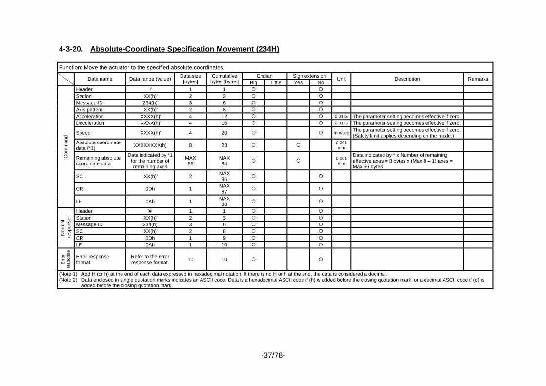
4-3-20. Absolute-Coordinate Specification Movement (234H) Function: Move the actuator to the specified absolute coordinates.
Endian Sign extension Data name Data range (value) Data size [bytes]
Cumulative bytes [bytes] Big Little Yes No
Unit Description Remarks
Header '!' 1 1 Station 'XX(h)' 2 3 Message ID '234(h)' 3 6 Axis pattern 'XX(h)' 2 8 Acceleration 'XXXX(h)' 4 12 0.01 G The parameter setting becomes effective if zero. Deceleration 'XXXX(h)' 4 16 0.01 G The parameter setting becomes effective if zero.
Speed 'XXXX(h)' 4 20 mm/sec The parameter setting becomes effective if zero.(Safety limit applies depending on the mode.)
Absolute coordinate data (*1) 'XXXXXXXX(h)' 8 28 0.001
mm
Remaining absolute coordinate data
Data indicated by *1 for the number of remaining axes
MAX 56
MAX 84 0.001
mm
Data indicated by * x Number of remaining effective axes = 8 bytes x (Max 8 – 1) axes = Max 56 bytes
SC 'XX(h)' 2 MAX 86
CR 0Dh 1 MAX 87
Com
man
d
LF 0Ah 1 MAX 88
Header '#' 1 1 Station 'XX(h)' 2 3 Message ID '234(h)' 3 6 SC 'XX(h)' 2 8 CR 0Dh 1 9
Nor
mal
re
spon
se
LF 0Ah 1 10
Erro
r re
spon
se
Error response format
Refer to the error response format. 10 10
(Note 1) Add H (or h) at the end of each data expressed in hexadecimal notation. If there is no H or h at the end, the data is considered a decimal. (Note 2) Data enclosed in single quotation marks indicates an ASCII code. Data is a hexadecimal ASCII code if (h) is added before the closing quotation mark, or a decimal ASCII code if (d) is
added before the closing quotation mark.
-38/78-
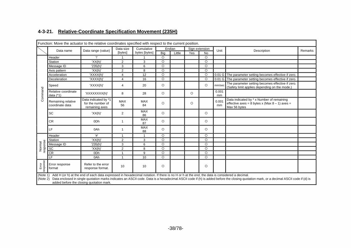
4-3-21. Relative-Coordinate Specification Movement (235H) Function: Move the actuator to the relative coordinates specified with respect to the current position.
Endian Sign extension Data name Data range (value) Data size [bytes]
Cumulative bytes [bytes] Big Little Yes No
Unit Description Remarks
Header '!' 1 1 Station 'XX(h)' 2 3 Message ID '235(h)' 3 6 Axis pattern 'XX(h)' 2 8 Acceleration 'XXXX(h)' 4 12 0.01 G The parameter setting becomes effective if zero. Deceleration 'XXXX(h)' 4 16 0.01 G The parameter setting becomes effective if zero.
Speed 'XXXX(h)' 4 20 mm/sec The parameter setting becomes effective if zero.(Safety limit applies depending on the mode.)
Relative coordinate data (*1) 'XXXXXXXX(h)' 8 28 0.001
mm
Remaining relative coordinate data
Data indicated by *1 for the number of remaining axes
MAX 56
MAX 84 0.001
mm
Data indicated by * x Number of remaining effective axes = 8 bytes x (Max 8 – 1) axes = Max 56 bytes
SC 'XX(h)' 2 MAX 86
CR 0Dh 1 MAX 87
Com
man
d
LF 0Ah 1 MAX 88
Header '#' 1 1 Station 'XX(h)' 2 3 Message ID '235(h)' 3 6 SC 'XX(h)' 2 8 CR 0Dh 1 9
Nor
mal
re
spon
se
LF 0Ah 1 10
Err
or
resp
onse
Error response format
Refer to the error response format. 10 10
(Note 1) Add H (or h) at the end of each data expressed in hexadecimal notation. If there is no H or h at the end, the data is considered a decimal. (Note 2) Data enclosed in single quotation marks indicates an ASCII code. Data is a hexadecimal ASCII code if (h) is added before the closing quotation mark, or a decimal ASCII code if (d) is
added before the closing quotation mark.
-39/78-
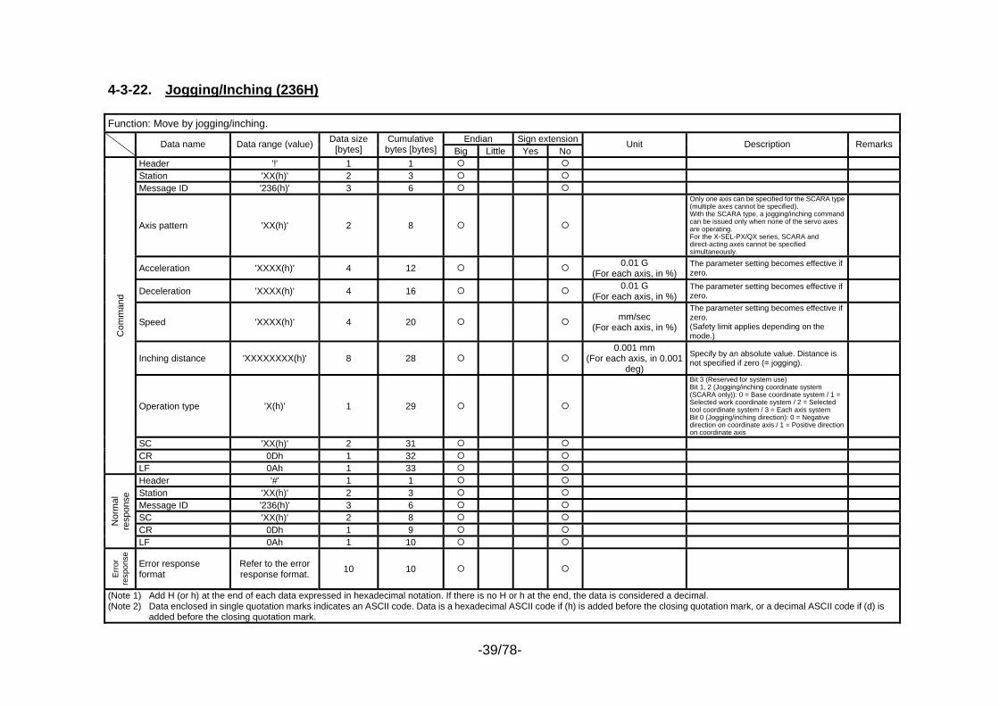
4-3-22. Jogging/Inching (236H) Function: Move by jogging/inching.
Endian Sign extension Data name Data range (value) Data size [bytes]
Cumulative bytes [bytes] Big Little Yes No
Unit Description Remarks
Header '!' 1 1 Station 'XX(h)' 2 3 Message ID '236(h)' 3 6
Axis pattern 'XX(h)' 2 8
Only one axis can be specified for the SCARA type (multiple axes cannot be specified). With the SCARA type, a jogging/inching command can be issued only when none of the servo axes are operating. For the X-SEL-PX/QX series, SCARA and direct-acting axes cannot be specified simultaneously.
Acceleration 'XXXX(h)' 4 12 0.01 G (For each axis, in %)
The parameter setting becomes effective if zero.
Deceleration 'XXXX(h)' 4 16 0.01 G (For each axis, in %)
The parameter setting becomes effective if zero.
Speed 'XXXX(h)' 4 20 mm/sec (For each axis, in %)
The parameter setting becomes effective if zero. (Safety limit applies depending on the mode.)
Inching distance 'XXXXXXXX(h)' 8 28 0.001 mm
(For each axis, in 0.001 deg)
Specify by an absolute value. Distance is not specified if zero (= jogging).
Operation type 'X(h)' 1 29
Bit 3 (Reserved for system use) Bit 1, 2 (Jogging/inching coordinate system (SCARA only)): 0 = Base coordinate system / 1 = Selected work coordinate system / 2 = Selected tool coordinate system / 3 = Each axis system Bit 0 (Jogging/inching direction): 0 = Negative direction on coordinate axis / 1 = Positive direction on coordinate axis
SC 'XX(h)' 2 31 CR 0Dh 1 32
Com
man
d
LF 0Ah 1 33 Header '#' 1 1 Station 'XX(h)' 2 3 Message ID '236(h)' 3 6 SC 'XX(h)' 2 8 CR 0Dh 1 9
Nor
mal
re
spon
se
LF 0Ah 1 10
Err
or
resp
onse
Error response format
Refer to the error response format. 10 10
(Note 1) Add H (or h) at the end of each data expressed in hexadecimal notation. If there is no H or h at the end, the data is considered a decimal. (Note 2) Data enclosed in single quotation marks indicates an ASCII code. Data is a hexadecimal ASCII code if (h) is added before the closing quotation mark, or a decimal ASCII code if (d) is
added before the closing quotation mark.
-40/78-
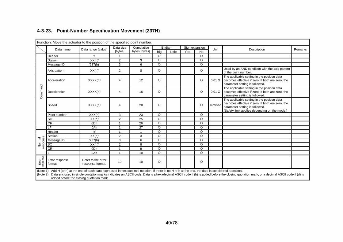
4-3-23. Point-Number Specification Movement (237H) Function: Move the actuator to the position of the specified point number.
Endian Sign extension Data name Data range (value) Data size [bytes]
Cumulative bytes [bytes] Big Little Yes No
Unit Description Remarks
Header '!' 1 1 Station 'XX(h)' 2 3 Message ID '237(h)' 3 6
Axis pattern 'XX(h)' 2 8 Used by an AND condition with the axis pattern of the point number.
Acceleration 'XXXX(h)' 4 12 0.01 G The applicable setting in the position data becomes effective if zero. If both are zero, the parameter setting is followed.
Deceleration 'XXXX(h)' 4 16 0.01 G The applicable setting in the position data becomes effective if zero. If both are zero, the parameter setting is followed.
Speed 'XXXX(h)' 4 20 mm/sec
The applicable setting in the position data becomes effective if zero. If both are zero, the parameter setting is followed. (Safety limit applies depending on the mode.)
Point number 'XXX(h)' 3 23 SC 'XX(h)' 2 25 CR 0Dh 1 26
Com
man
d
LF 0Ah 1 27 Header '#' 1 1 Station 'XX(h)' 2 3 Message ID '237(h)' 3 6 SC 'XX(h)' 2 8 CR 0Dh 1 9
Nor
mal
re
spon
se
LF 0Ah 1 10
Err
or
resp
onse
Error response format
Refer to the error response format. 10 10
(Note 1) Add H (or h) at the end of each data expressed in hexadecimal notation. If there is no H or h at the end, the data is considered a decimal. (Note 2) Data enclosed in single quotation marks indicates an ASCII code. Data is a hexadecimal ASCII code if (h) is added before the closing quotation mark, or a decimal ASCII code if (d) is
added before the closing quotation mark.
-41/78-
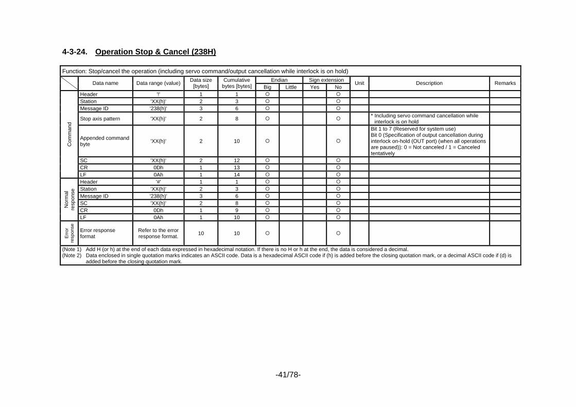
4-3-24. Operation Stop & Cancel (238H) Function: Stop/cancel the operation (including servo command/output cancellation while interlock is on hold)
Endian Sign extension Data name Data range (value) Data size [bytes]
Cumulative bytes [bytes] Big Little Yes No
Unit Description Remarks
Header '!' 1 1 Station 'XX(h)' 2 3 Message ID '238(h)' 3 6
Stop axis pattern 'XX(h)' 2 8 * Including servo command cancellation while interlock is on hold
Appended command byte 'XX(h)' 2 10
Bit 1 to 7 (Reserved for system use) Bit 0 (Specification of output cancellation during interlock on-hold (OUT port) (when all operations are paused)): 0 = Not canceled / 1 = Canceled tentatively
SC 'XX(h)' 2 12 CR 0Dh 1 13
Com
man
d
LF 0Ah 1 14 Header '#' 1 1 Station 'XX(h)' 2 3 Message ID '238(h)' 3 6 SC 'XX(h)' 2 8 CR 0Dh 1 9
Nor
mal
re
spon
se
LF 0Ah 1 10
Err
or
resp
onse
Error response format
Refer to the error response format. 10 10
(Note 1) Add H (or h) at the end of each data expressed in hexadecimal notation. If there is no H or h at the end, the data is considered a decimal. (Note 2) Data enclosed in single quotation marks indicates an ASCII code. Data is a hexadecimal ASCII code if (h) is added before the closing quotation mark, or a decimal ASCII code if (d) is
added before the closing quotation mark.
-42/78-
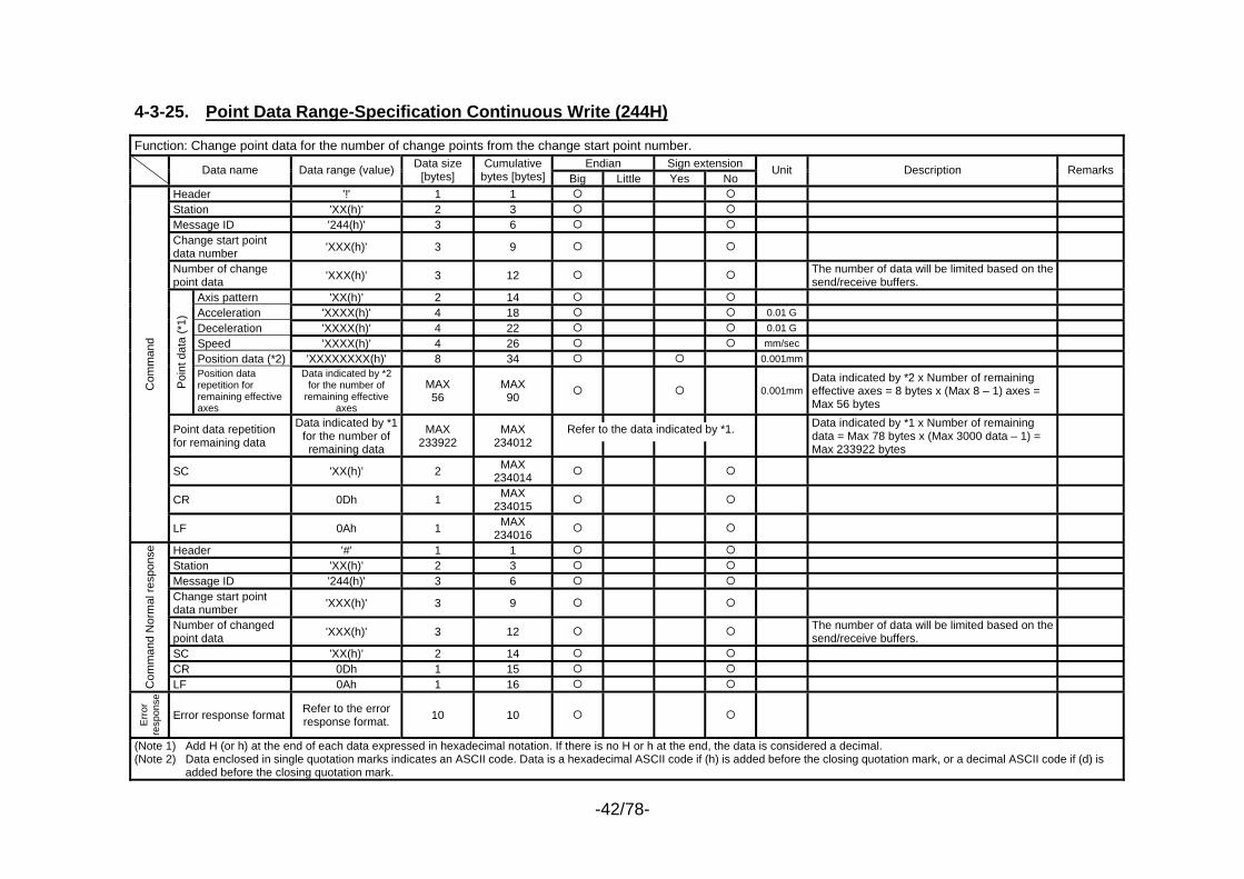
4-3-25. Point Data Range-Specification Continuous Write (244H) Function: Change point data for the number of change points from the change start point number.
Endian Sign extension Data name Data range (value) Data size [bytes]
Cumulative bytes [bytes] Big Little Yes No
Unit Description Remarks
Header '!' 1 1 Station 'XX(h)' 2 3 Message ID '244(h)' 3 6 Change start point data number 'XXX(h)' 3 9
Number of change point data 'XXX(h)' 3 12 The number of data will be limited based on the
send/receive buffers.
Axis pattern 'XX(h)' 2 14 Acceleration 'XXXX(h)' 4 18 0.01 G Deceleration 'XXXX(h)' 4 22 0.01 G Speed 'XXXX(h)' 4 26 mm/sec Position data (*2) 'XXXXXXXX(h)' 8 34 0.001mm
Poi
nt d
ata
(*1)
Position data repetition for remaining effective axes
Data indicated by *2 for the number of
remaining effective axes
MAX 56
MAX 90 0.001mm
Data indicated by *2 x Number of remaining effective axes = 8 bytes x (Max 8 – 1) axes = Max 56 bytes
Point data repetition for remaining data
Data indicated by *1 for the number of remaining data
MAX 233922
MAX 234012
Data indicated by *1 x Number of remaining data = Max 78 bytes x (Max 3000 data – 1) = Max 233922 bytes
SC 'XX(h)' 2 MAX 234014
CR 0Dh 1 MAX 234015
Com
man
d
LF 0Ah 1 MAX 234016
Header '#' 1 1 Station 'XX(h)' 2 3 Message ID '244(h)' 3 6 Change start point data number 'XXX(h)' 3 9
Number of changed point data 'XXX(h)' 3 12 The number of data will be limited based on the
send/receive buffers.
SC 'XX(h)' 2 14 CR 0Dh 1 15
Com
man
d N
orm
al re
spon
se
LF 0Ah 1 16
Err
or
resp
onse
Error response format Refer to the error response format. 10 10
(Note 1) Add H (or h) at the end of each data expressed in hexadecimal notation. If there is no H or h at the end, the data is considered a decimal. (Note 2) Data enclosed in single quotation marks indicates an ASCII code. Data is a hexadecimal ASCII code if (h) is added before the closing quotation mark, or a decimal ASCII code if (d) is
added before the closing quotation mark.
Refer to the data indicated by *1.
-43/78-
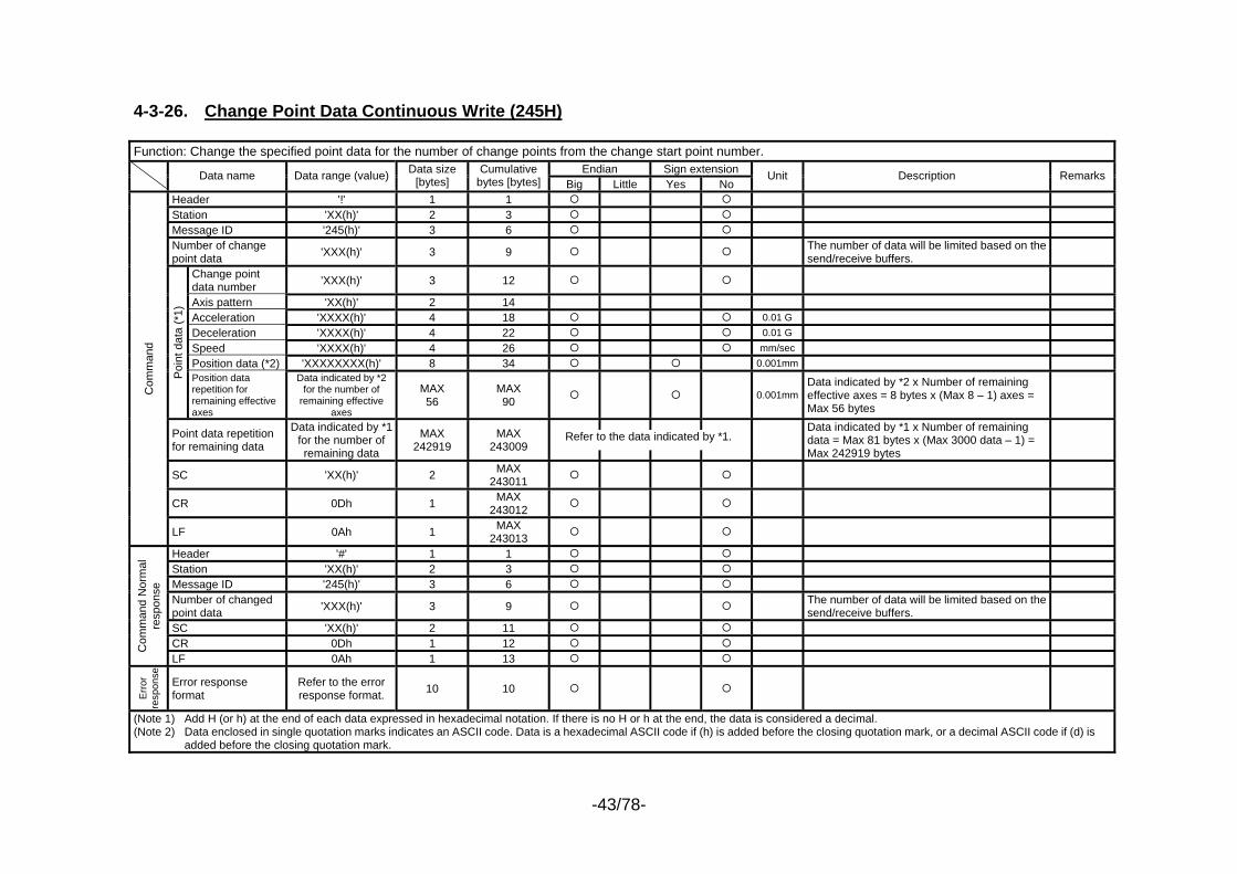
4-3-26. Change Point Data Continuous Write (245H) Function: Change the specified point data for the number of change points from the change start point number.
Endian Sign extension Data name Data range (value) Data size [bytes]
Cumulative bytes [bytes] Big Little Yes No
Unit Description Remarks
Header '!' 1 1 Station 'XX(h)' 2 3 Message ID '245(h)' 3 6 Number of change point data 'XXX(h)' 3 9 The number of data will be limited based on the
send/receive buffers.
Change point data number 'XXX(h)' 3 12
Axis pattern 'XX(h)' 2 14 Acceleration 'XXXX(h)' 4 18 0.01 G Deceleration 'XXXX(h)' 4 22 0.01 G Speed 'XXXX(h)' 4 26 mm/sec Position data (*2) 'XXXXXXXX(h)' 8 34 0.001mm
Poi
nt d
ata
(*1)
Position data repetition for remaining effective axes
Data indicated by *2 for the number of
remaining effective axes
MAX 56
MAX 90 0.001mm
Data indicated by *2 x Number of remaining effective axes = 8 bytes x (Max 8 – 1) axes = Max 56 bytes
Point data repetition for remaining data
Data indicated by *1 for the number of remaining data
MAX 242919
MAX 243009
Data indicated by *1 x Number of remaining data = Max 81 bytes x (Max 3000 data – 1) = Max 242919 bytes
SC 'XX(h)' 2 MAX 243011
CR 0Dh 1 MAX 243012
Com
man
d
LF 0Ah 1 MAX 243013
Header '#' 1 1 Station 'XX(h)' 2 3 Message ID '245(h)' 3 6 Number of changed point data 'XXX(h)' 3 9 The number of data will be limited based on the
send/receive buffers.
SC 'XX(h)' 2 11 CR 0Dh 1 12 C
omm
and
Nor
mal
re
spon
se
LF 0Ah 1 13
Err
or
resp
onse
Error response format
Refer to the error response format. 10 10
(Note 1) Add H (or h) at the end of each data expressed in hexadecimal notation. If there is no H or h at the end, the data is considered a decimal. (Note 2) Data enclosed in single quotation marks indicates an ASCII code. Data is a hexadecimal ASCII code if (h) is added before the closing quotation mark, or a decimal ASCII code if (d) is
added before the closing quotation mark.
Refer to the data indicated by *1.
-44/78-
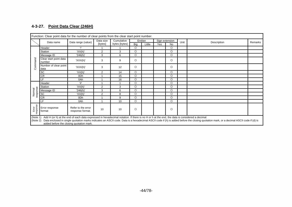
4-3-27. Point Data Clear (246H) Function: Clear point data for the number of clear points from the clear start point number.
Endian Sign extension Data name Data range (value) Data size [bytes]
Cumulative bytes [bytes] Big Little Yes No
Unit Description Remarks
Header '!' 1 1 Station 'XX(h)' 2 3 Message ID '246(h)' 3 6 Clear start point data number 'XXX(h)' 3 9
Number of clear point data 'XXX(h)' 3 12
SC 'XX(h)' 2 14 CR 0Dh 1 15
Com
man
d
LF 0Ah 1 16 Header '#' 1 1 Station 'XX(h)' 2 3 Message ID '246(h)' 3 6 SC 'XX(h)' 2 8 CR 0Dh 1 9
Nor
mal
re
spon
se
LF 0Ah 1 10
Err
or
resp
onse
Error response format
Refer to the error response format. 10 10
(Note 1) Add H (or h) at the end of each data expressed in hexadecimal notation. If there is no H or h at the end, the data is considered a decimal. (Note 2) Data enclosed in single quotation marks indicates an ASCII code. Data is a hexadecimal ASCII code if (h) is added before the closing quotation mark, or a decimal ASCII code if (d) is
added before the closing quotation mark.
-45/78-
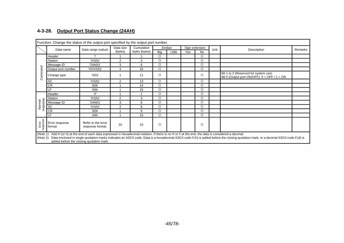
4-3-28. Output Port Status Change (24AH) Function: Change the status of the output port specified by the output port number.
Endian Sign extension Data name Data range (value) Data size [bytes]
Cumulative bytes [bytes] Big Little Yes No
Unit Description Remarks
Header '!' 1 1 Station 'XX(h)' 2 3 Message ID '24A(h)' 3 6 Output port number 'XXXX(h)' 4 10
Change type 'X(h)' 1 11 Bit 1 to 3 (Reserved for system use) Bit 0 (Output port ON/OFF): 0 = OFF / 1 = ON
SC 'XX(h)' 2 13 CR 0Dh 1 14
Com
man
d
LF 0Ah 1 15 Header '#' 1 1 Station 'XX(h)' 2 3 Message ID '24A(h)' 3 6 SC 'XX(h)' 2 8 CR 0Dh 1 9
Nor
mal
re
spon
se
LF 0Ah 1 10
Err
or
resp
onse
Error response format
Refer to the error response format. 10 10
(Note 1) Add H (or h) at the end of each data expressed in hexadecimal notation. If there is no H or h at the end, the data is considered a decimal. (Note 2) Data enclosed in single quotation marks indicates an ASCII code. Data is a hexadecimal ASCII code if (h) is added before the closing quotation mark, or a decimal ASCII code if (d) is
added before the closing quotation mark.
-46/78-
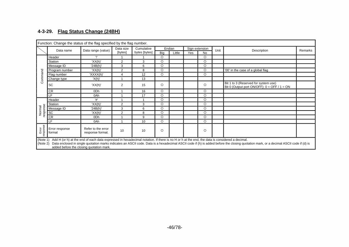
4-3-29. Flag Status Change (24BH) Function: Change the status of the flag specified by the flag number.
Endian Sign extension Data name Data range (value) Data size [bytes]
Cumulative bytes [bytes] Big Little Yes No
Unit Description Remarks
Header '!' 1 1 Station 'XX(h)' 2 3 Message ID '24B(h)' 3 6 Program number 'XX(h)' 2 8 ‘00’ in the case of a global flag Flag number 'XXXX(h)' 4 12 Change type 'X(h)' 1 13
SC 'XX(h)' 2 15 Bit 1 to 3 (Reserved for system use) Bit 0 (Output port ON/OFF): 0 = OFF / 1 = ON
CR 0Dh 1 16
Com
man
d
LF 0Ah 1 17 Header '#' 1 1 Station 'XX(h)' 2 3 Message ID '24B(h)' 3 6 SC 'XX(h)' 2 8 CR 0Dh 1 9
Nor
mal
re
spon
se
LF 0Ah 1 10
Erro
r re
spon
se
Error response format
Refer to the error response format. 10 10
(Note 1) Add H (or h) at the end of each data expressed in hexadecimal notation. If there is no H or h at the end, the data is considered a decimal. (Note 2) Data enclosed in single quotation marks indicates an ASCII code. Data is a hexadecimal ASCII code if (h) is added before the closing quotation mark, or a decimal ASCII code if (d) is
added before the closing quotation mark.
-47/78-
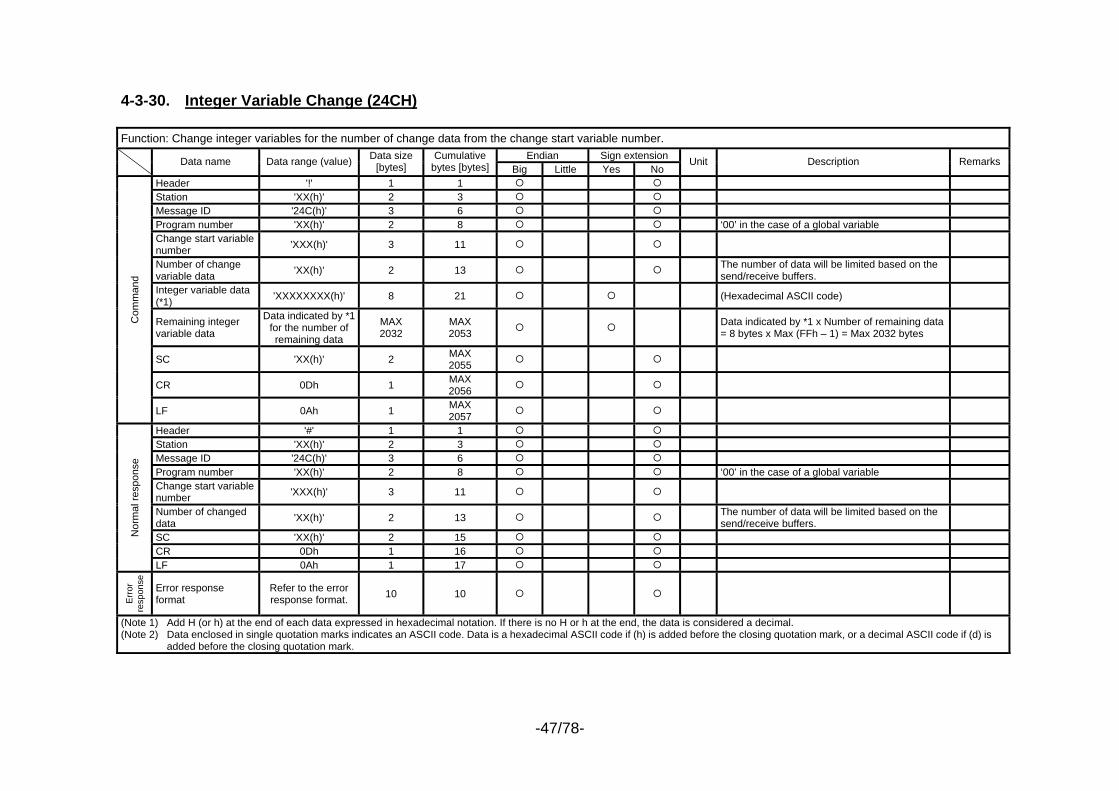
4-3-30. Integer Variable Change (24CH) Function: Change integer variables for the number of change data from the change start variable number.
Endian Sign extension Data name Data range (value) Data size [bytes]
Cumulative bytes [bytes] Big Little Yes No
Unit Description Remarks
Header '!' 1 1 Station 'XX(h)' 2 3 Message ID '24C(h)' 3 6 Program number 'XX(h)' 2 8 ‘00’ in the case of a global variable Change start variable number 'XXX(h)' 3 11
Number of change variable data 'XX(h)' 2 13 The number of data will be limited based on the
send/receive buffers.
Integer variable data (*1) 'XXXXXXXX(h)' 8 21 (Hexadecimal ASCII code)
Remaining integer variable data
Data indicated by *1 for the number of remaining data
MAX 2032
MAX 2053 Data indicated by *1 x Number of remaining data
= 8 bytes x Max (FFh – 1) = Max 2032 bytes
SC 'XX(h)' 2 MAX 2055
CR 0Dh 1 MAX 2056
Com
man
d
LF 0Ah 1 MAX 2057
Header '#' 1 1 Station 'XX(h)' 2 3 Message ID '24C(h)' 3 6 Program number 'XX(h)' 2 8 ‘00’ in the case of a global variable Change start variable number 'XXX(h)' 3 11
Number of changed data 'XX(h)' 2 13 The number of data will be limited based on the
send/receive buffers.
SC 'XX(h)' 2 15 CR 0Dh 1 16
Nor
mal
resp
onse
LF 0Ah 1 17
Err
or
resp
onse
Error response format
Refer to the error response format. 10 10
(Note 1) Add H (or h) at the end of each data expressed in hexadecimal notation. If there is no H or h at the end, the data is considered a decimal. (Note 2) Data enclosed in single quotation marks indicates an ASCII code. Data is a hexadecimal ASCII code if (h) is added before the closing quotation mark, or a decimal ASCII code if (d) is
added before the closing quotation mark.
-48/78-
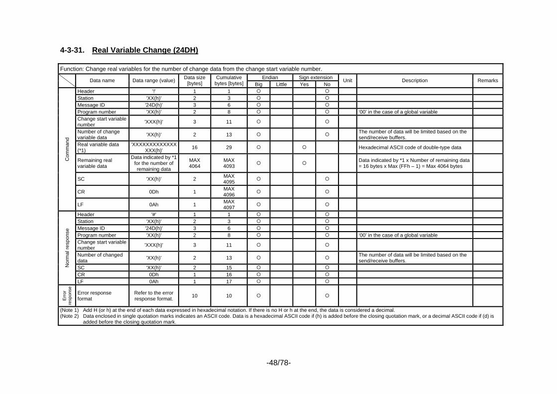
4-3-31. Real Variable Change (24DH) Function: Change real variables for the number of change data from the change start variable number.
Endian Sign extension Data name Data range (value) Data size [bytes]
Cumulative bytes [bytes] Big Little Yes No
Unit Description Remarks
Header '!' 1 1 Station 'XX(h)' 2 3 Message ID '24D(h)' 3 6 Program number 'XX(h)' 2 8 ‘00’ in the case of a global variable Change start variable number 'XXX(h)' 3 11
Number of change variable data 'XX(h)' 2 13 The number of data will be limited based on the
send/receive buffers.
Real variable data (*1)
'XXXXXXXXXXXXXXXX(h)' 16 29 Hexadecimal ASCII code of double-type data
Remaining real variable data
Data indicated by *1 for the number of remaining data
MAX 4064
MAX 4093 Data indicated by *1 x Number of remaining data
= 16 bytes x Max (FFh – 1) = Max 4064 bytes
SC 'XX(h)' 2 MAX 4095
CR 0Dh 1 MAX 4096
Com
man
d
LF 0Ah 1 MAX 4097
Header '#' 1 1 Station 'XX(h)' 2 3 Message ID '24D(h)' 3 6 Program number 'XX(h)' 2 8 ‘00’ in the case of a global variable Change start variable number 'XXX(h)' 3 11
Number of changed data 'XX(h)' 2 13 The number of data will be limited based on the
send/receive buffers.
SC 'XX(h)' 2 15 CR 0Dh 1 16
Nor
mal
resp
onse
LF 0Ah 1 17
Err
or
resp
onse
Error response format
Refer to the error response format. 10 10
(Note 1) Add H (or h) at the end of each data expressed in hexadecimal notation. If there is no H or h at the end, the data is considered a decimal. (Note 2) Data enclosed in single quotation marks indicates an ASCII code. Data is a hexadecimal ASCII code if (h) is added before the closing quotation mark, or a decimal ASCII code if (d) is
added before the closing quotation mark.
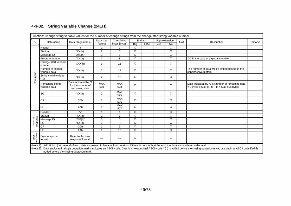
-49/78-
4-3-32. String Variable Change (24EH) Function: Change string variable values for the number of change strings from the change start string variable number.
Endian Sign extension Data name Data range (value) Data size [bytes]
Cumulative bytes [bytes] Big Little Yes No
Unit Description Remarks
Header '!' 1 1 Station 'XX(h)' 2 3 Message ID '24E(h)' 3 6 Program number 'XX(h)' 2 8 ‘00’ in the case of a global variable Change start variable number 'XXX(h)' 3 11
Number of change variable data 'XX(h)' 2 13 The number of data will be limited based on the
send/receive buffers.
String variable data (*1) 'XX(h)' 2 15
Remaining string variable data
Data indicated by *1 for the number of remaining data
MAX 508
MAX 523 Data indicated by *1 x Number of remaining data
= 2 bytes x Max (FFh – 1) = Max 508 bytes
SC 'XX(h)' 2 MAX 525
CR 0Dh 1 MAX 526
Com
man
d
LF 0Ah 1 MAX 527
Header '#' 1 1 Station 'XX(h)' 2 3 Message ID '24E(h)' 3 6 SC 'XX(h)' 2 8 CR 0Dh 1 9
Nor
mal
re
spon
se
LF 0Ah 1 10
Err
or
resp
onse
Error response format
Refer to the error response format. 10 10
(Note 1) Add H (or h) at the end of each data expressed in hexadecimal notation. If there is no H or h at the end, the data is considered a decimal. (Note 2) Data enclosed in single quotation marks indicates an ASCII code. Data is a hexadecimal ASCII code if (h) is added before the closing quotation mark, or a decimal ASCII code if (d) is
added before the closing quotation mark.
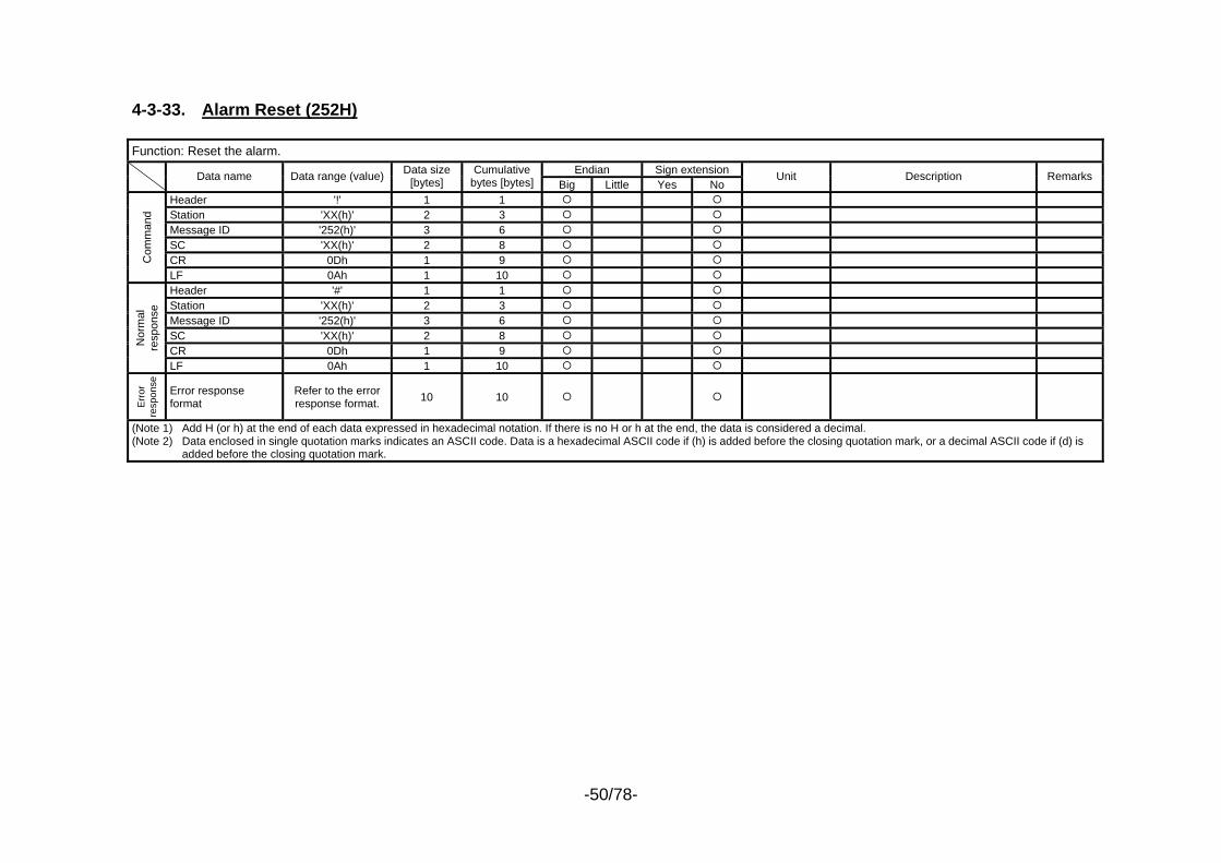
-50/78-
4-3-33. Alarm Reset (252H) Function: Reset the alarm.
Endian Sign extension Data name Data range (value) Data size [bytes]
Cumulative bytes [bytes] Big Little Yes No
Unit Description Remarks
Header '!' 1 1 Station 'XX(h)' 2 3 Message ID '252(h)' 3 6 SC 'XX(h)' 2 8 CR 0Dh 1 9 C
omm
and
LF 0Ah 1 10 Header '#' 1 1 Station 'XX(h)' 2 3 Message ID '252(h)' 3 6 SC 'XX(h)' 2 8 CR 0Dh 1 9
Nor
mal
re
spon
se
LF 0Ah 1 10
Err
or
resp
onse
Error response format
Refer to the error response format. 10 10
(Note 1) Add H (or h) at the end of each data expressed in hexadecimal notation. If there is no H or h at the end, the data is considered a decimal. (Note 2) Data enclosed in single quotation marks indicates an ASCII code. Data is a hexadecimal ASCII code if (h) is added before the closing quotation mark, or a decimal ASCII code if (d) is
added before the closing quotation mark.
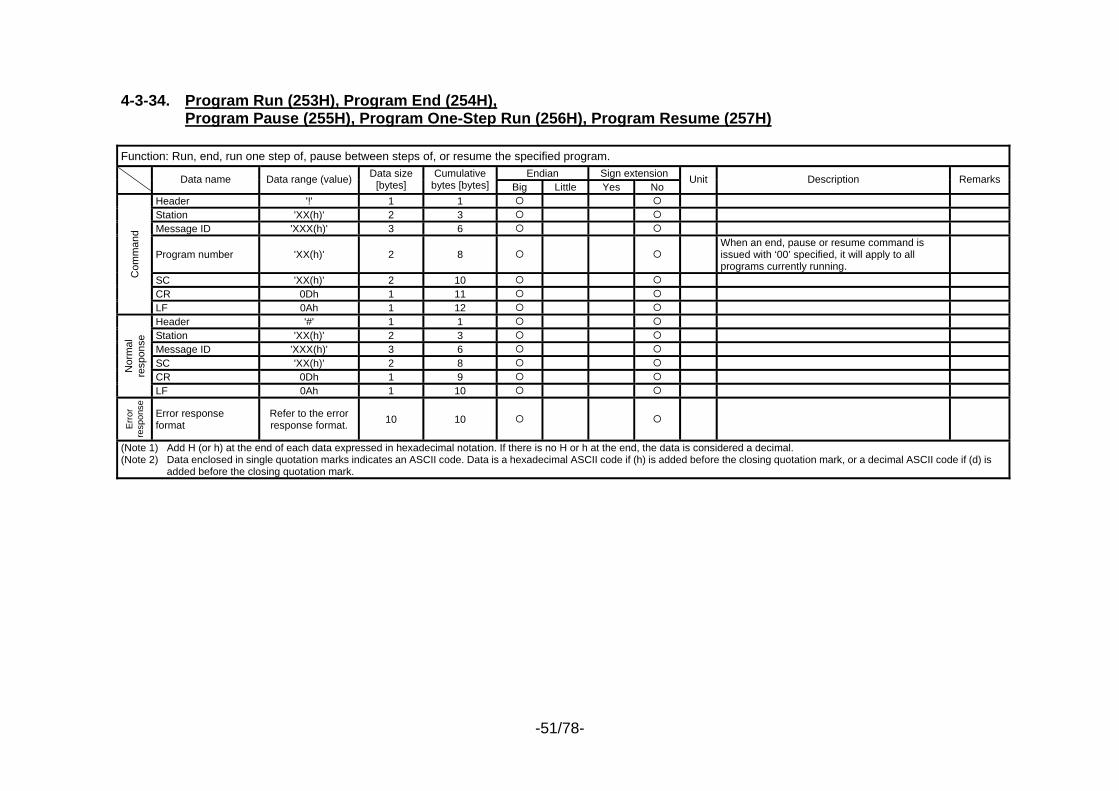
-51/78-
4-3-34. Program Run (253H), Program End (254H),
Program Pause (255H), Program One-Step Run (256H), Program Resume (257H) Function: Run, end, run one step of, pause between steps of, or resume the specified program.
Endian Sign extension Data name Data range (value) Data size [bytes]
Cumulative bytes [bytes] Big Little Yes No
Unit Description Remarks
Header '!' 1 1 Station 'XX(h)' 2 3 Message ID 'XXX(h)' 3 6
Program number 'XX(h)' 2 8 When an end, pause or resume command is issued with ‘00’ specified, it will apply to all programs currently running.
SC 'XX(h)' 2 10 CR 0Dh 1 11
Com
man
d
LF 0Ah 1 12 Header '#' 1 1 Station 'XX(h)' 2 3 Message ID 'XXX(h)' 3 6 SC 'XX(h)' 2 8 CR 0Dh 1 9
Nor
mal
re
spon
se
LF 0Ah 1 10
Err
or
resp
onse
Error response format
Refer to the error response format. 10 10
(Note 1) Add H (or h) at the end of each data expressed in hexadecimal notation. If there is no H or h at the end, the data is considered a decimal. (Note 2) Data enclosed in single quotation marks indicates an ASCII code. Data is a hexadecimal ASCII code if (h) is added before the closing quotation mark, or a decimal ASCII code if (d) is
added before the closing quotation mark.

-52/78-
4-3-35. Software Reset (25BH) Function: Reset the software.
Endian Sign extension Data name Data range (value) Data size [bytes]
Cumulative bytes [bytes] Big Little Yes No
Unit Description Remarks
Header '!' 1 1 Station 'XX(h)' 2 3 Message ID '25B(h)' 3 6 SC 'XX(h)' 2 8 CR 0Dh 1 9 C
omm
and
LF 0Ah 1 10
Nor
mal
re
spon
se
0 0
No normal response. * The controller will become reception-ready
upon elapse of approx. 10 seconds after this command is transmitted (as of June 26, 2001).
Err
or
resp
onse
Error response format
Refer to the error response format. 10 10
(Note 1) Add H (or h) at the end of each data expressed in hexadecimal notation. If there is no H or h at the end, the data is considered a decimal. (Note 2) Data enclosed in single quotation marks indicates an ASCII code. Data is a hexadecimal ASCII code if (h) is added before the closing quotation mark, or a decimal ASCII code if (d) is
added before the closing quotation mark.

-53/78-
4-3-36. Drive-Source Recovery Request (25CH) Function: Request recovery of the drive source.
Endian Sign extension Data name Data range (value) Data size [bytes]
Cumulative bytes [bytes] Big Little Yes No
Unit Description Remarks
Header '!' 1 1 Station 'XX(h)' 2 3 Message ID '25C(h)' 3 6 SC 'XX(h)' 2 8 CR 0Dh 1 9 C
omm
and
LF 0Ah 1 10 Header '#' 1 1 Station 'XX(h)' 2 3 Message ID '25C(h)' 3 6 SC 'XX(h)' 2 8 CR 0Dh 1 9
Nor
mal
re
spon
se
LF 0Ah 1 10
Err
or
resp
onse
Error response format
Refer to the error response format. 10 10
(Note 1) Add H (or h) at the end of each data expressed in hexadecimal notation. If there is no H or h at the end, the data is considered a decimal. (Note 2) Data enclosed in single quotation marks indicates an ASCII code. Data is a hexadecimal ASCII code if (h) is added before the closing quotation mark, or a decimal ASCII code if (d) is
added before the closing quotation mark.
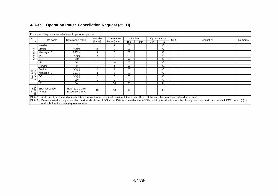
-54/78-
4-3-37. Operation Pause Cancellation Request (25EH) Function: Request cancellation of operation pause.
Endian Sign extension Data name Data range (value) Data size [bytes]
Cumulative bytes [bytes] Big Little Yes No
Unit Description Remarks
Header '!' 1 1 Station 'XX(h)' 2 3 Message ID '25E(h)' 3 6 SC 'XX(h)' 2 8 CR 0Dh 1 9 C
omm
and
LF 0Ah 1 10 Header '#' 1 1 Station 'XX(h)' 2 3 Message ID '25E(h)' 3 6 SC 'XX(h)' 2 8 CR 0Dh 1 9
Nor
mal
re
spon
se
LF 0Ah 1 10
Err
or
resp
onse
Error response format
Refer to the error response format. 10 10
(Note 1) Add H (or h) at the end of each data expressed in hexadecimal notation. If there is no H or h at the end, the data is considered a decimal. (Note 2) Data enclosed in single quotation marks indicates an ASCII code. Data is a hexadecimal ASCII code if (h) is added before the closing quotation mark, or a decimal ASCII code if (d) is
added before the closing quotation mark.
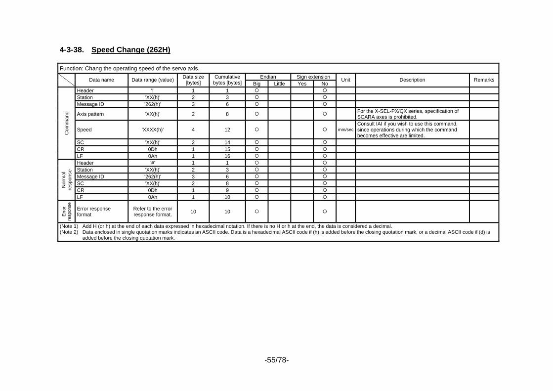
-55/78-
4-3-38. Speed Change (262H) Function: Chang the operating speed of the servo axis.
Endian Sign extension Data name Data range (value) Data size [bytes]
Cumulative bytes [bytes] Big Little Yes No
Unit Description Remarks
Header '!' 1 1 Station 'XX(h)' 2 3 Message ID '262(h)' 3 6
Axis pattern 'XX(h)' 2 8 For the X-SEL-PX/QX series, specification of SCARA axes is prohibited.
Speed 'XXXX(h)' 4 12 mm/secConsult IAI if you wish to use this command, since operations during which the command becomes effective are limited.
SC 'XX(h)' 2 14 CR 0Dh 1 15
Com
man
d
LF 0Ah 1 16 Header '#' 1 1 Station 'XX(h)' 2 3 Message ID '262(h)' 3 6 SC 'XX(h)' 2 8 CR 0Dh 1 9
Nor
mal
re
spon
se
LF 0Ah 1 10
Err
or
resp
onse
Error response format
Refer to the error response format. 10 10
(Note 1) Add H (or h) at the end of each data expressed in hexadecimal notation. If there is no H or h at the end, the data is considered a decimal. (Note 2) Data enclosed in single quotation marks indicates an ASCII code. Data is a hexadecimal ASCII code if (h) is added before the closing quotation mark, or a decimal ASCII code if (d) is
added before the closing quotation mark.
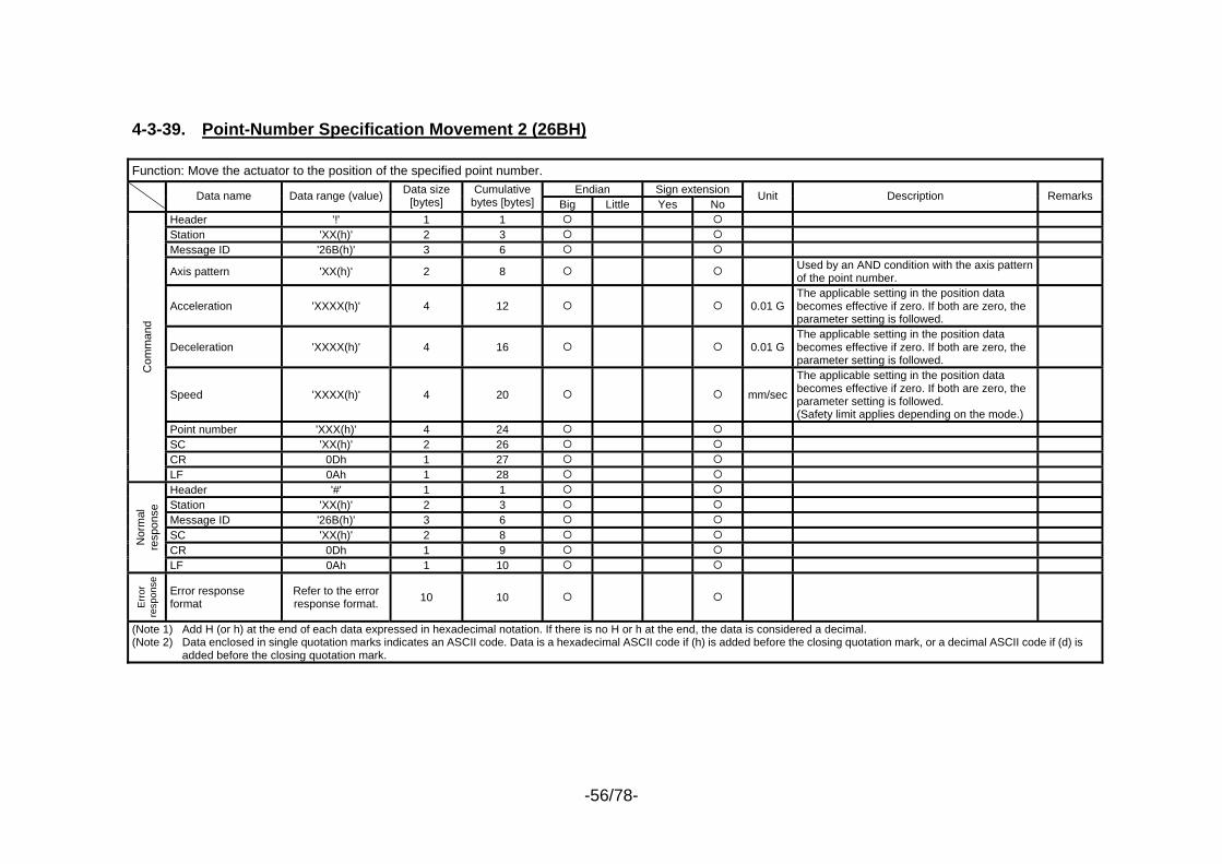
-56/78-
4-3-39. Point-Number Specification Movement 2 (26BH) Function: Move the actuator to the position of the specified point number.
Endian Sign extension Data name Data range (value) Data size [bytes]
Cumulative bytes [bytes] Big Little Yes No
Unit Description Remarks
Header '!' 1 1 Station 'XX(h)' 2 3 Message ID '26B(h)' 3 6
Axis pattern 'XX(h)' 2 8 Used by an AND condition with the axis pattern of the point number.
Acceleration 'XXXX(h)' 4 12 0.01 G The applicable setting in the position data becomes effective if zero. If both are zero, the parameter setting is followed.
Deceleration 'XXXX(h)' 4 16 0.01 G The applicable setting in the position data becomes effective if zero. If both are zero, the parameter setting is followed.
Speed 'XXXX(h)' 4 20 mm/sec
The applicable setting in the position data becomes effective if zero. If both are zero, the parameter setting is followed. (Safety limit applies depending on the mode.)
Point number 'XXX(h)' 4 24 SC 'XX(h)' 2 26 CR 0Dh 1 27
Com
man
d
LF 0Ah 1 28 Header '#' 1 1 Station 'XX(h)' 2 3 Message ID '26B(h)' 3 6 SC 'XX(h)' 2 8 CR 0Dh 1 9
Nor
mal
re
spon
se
LF 0Ah 1 10
Err
or
resp
onse
Error response format
Refer to the error response format. 10 10
(Note 1) Add H (or h) at the end of each data expressed in hexadecimal notation. If there is no H or h at the end, the data is considered a decimal. (Note 2) Data enclosed in single quotation marks indicates an ASCII code. Data is a hexadecimal ASCII code if (h) is added before the closing quotation mark, or a decimal ASCII code if (d) is
added before the closing quotation mark.

-57/78-
4-3-40. Point Data Range-Specification Continuous Write 2 (26CH) Function: Change point data for the number of change points from the change start point number.
Endian Sign extension Data name Data range (value) Data size [bytes]
Cumulative bytes [bytes] Big Little Yes No
Unit Description Remarks
Header '!' 1 1 Station 'XX(h)' 2 3 Message ID '26C(h)' 3 6 Change start point data number 'XXXX(h)' 4 10
Number of change point data 'XXXX(h)' 4 14 The number of data will be limited based on the
send/receive buffers.
Axis pattern 'XX(h)' 2 16 Acceleration 'XXXX(h)' 4 20 0.01 G Deceleration 'XXXX(h)' 4 24 0.01 G Speed 'XXXX(h)' 4 28 mm/sec Position data (*2) 'XXXXXXXX(h)' 8 36 0.001mm
Poi
nt d
ata
(*1)
Position data repetition for remaining effective axes
Data indicated by *2 for the number of
remaining effective axes
MAX 56
MAX 92 0.001mm
Data indicated by *2 x Number of remaining effective axes = 8 bytes x (Max 8 – 1) axes = Max 56 bytes
Point data repetition for remaining data
Data indicated by *1 for the number of remaining data
MAX 1559922
MAX 1560014
Data indicated by *1 x Number of remaining data = Max 78 bytes x (Max 20000 data – 1) = Max 1559922 bytes
SC 'XX(h)' 2 MAX 1560016
CR 0Dh 1 MAX 1560017
Com
man
d
LF 0Ah 1 MAX 1560018
Header '#' 1 1 Station 'XX(h)' 2 3 Message ID '26C(h)' 3 6 Change start point data number 'XXXX(h)' 4 10
Number of changed point data 'XXXX(h)' 4 14 The number of data will be limited based on the
send/receive buffers.
SC 'XX(h)' 2 16 CR 0Dh 1 17
Com
man
d N
orm
al re
spon
se
LF 0Ah 1 18
Err
or
resp
onse
Error response format Refer to the error response format. 10 10
(Note 1) Add H (or h) at the end of each data expressed in hexadecimal notation. If there is no H or h at the end, the data is considered a decimal. (Note 2) Data enclosed in single quotation marks indicates an ASCII code. Data is a hexadecimal ASCII code if (h) is added before the closing quotation mark, or a decimal ASCII code if (d) is
added before the closing quotation mark.
Refer to the data indicated by *1.
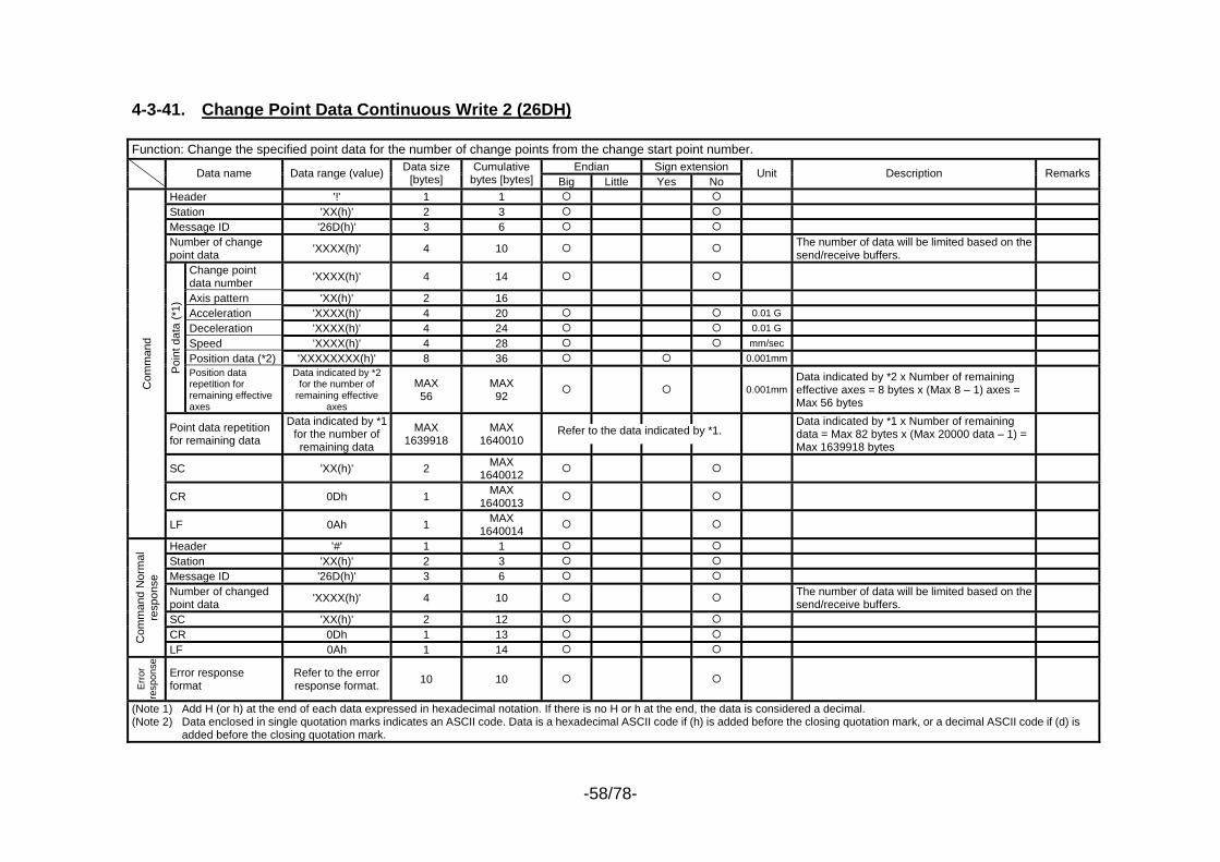
-58/78-
4-3-41. Change Point Data Continuous Write 2 (26DH) Function: Change the specified point data for the number of change points from the change start point number.
Endian Sign extension Data name Data range (value) Data size [bytes]
Cumulative bytes [bytes] Big Little Yes No
Unit Description Remarks
Header '!' 1 1 Station 'XX(h)' 2 3 Message ID '26D(h)' 3 6 Number of change point data 'XXXX(h)' 4 10 The number of data will be limited based on the
send/receive buffers.
Change point data number 'XXXX(h)' 4 14
Axis pattern 'XX(h)' 2 16 Acceleration 'XXXX(h)' 4 20 0.01 G Deceleration 'XXXX(h)' 4 24 0.01 G Speed 'XXXX(h)' 4 28 mm/sec Position data (*2) 'XXXXXXXX(h)' 8 36 0.001mm
Poi
nt d
ata
(*1)
Position data repetition for remaining effective axes
Data indicated by *2 for the number of
remaining effective axes
MAX 56
MAX 92 0.001mm
Data indicated by *2 x Number of remaining effective axes = 8 bytes x (Max 8 – 1) axes = Max 56 bytes
Point data repetition for remaining data
Data indicated by *1 for the number of remaining data
MAX 1639918
MAX 1640010
Data indicated by *1 x Number of remaining data = Max 82 bytes x (Max 20000 data – 1) = Max 1639918 bytes
SC 'XX(h)' 2 MAX 1640012
CR 0Dh 1 MAX 1640013
Com
man
d
LF 0Ah 1 MAX 1640014
Header '#' 1 1 Station 'XX(h)' 2 3 Message ID '26D(h)' 3 6 Number of changed point data 'XXXX(h)' 4 10 The number of data will be limited based on the
send/receive buffers.
SC 'XX(h)' 2 12 CR 0Dh 1 13 C
omm
and
Nor
mal
re
spon
se
LF 0Ah 1 14
Err
or
resp
onse
Error response format
Refer to the error response format. 10 10
(Note 1) Add H (or h) at the end of each data expressed in hexadecimal notation. If there is no H or h at the end, the data is considered a decimal. (Note 2) Data enclosed in single quotation marks indicates an ASCII code. Data is a hexadecimal ASCII code if (h) is added before the closing quotation mark, or a decimal ASCII code if (d) is
added before the closing quotation mark.
Refer to the data indicated by *1.

-59/78-
4-3-42. Point Data Clear 2 (26EH) Function: Clear point data for the number of clear points from the clear start point number.
Endian Sign extension Data name Data range (value) Data size [bytes]
Cumulative bytes [bytes] Big Little Yes No
Unit Description Remarks
Header '!' 1 1 Station 'XX(h)' 2 3 Message ID '26E(h)' 3 6 Clear start point data number 'XXXX(h)' 4 10
Number of clear point data 'XXXX(h)' 4 14
SC 'XX(h)' 2 16 CR 0Dh 1 17
Com
man
d
LF 0Ah 1 18 Header '#' 1 1 Station 'XX(h)' 2 3 Message ID '26E(h)' 3 6 SC 'XX(h)' 2 8 CR 0Dh 1 9
Nor
mal
re
spon
se
LF 0Ah 1 10
Err
or
resp
onse
Error response format
Refer to the error response format. 10 10
(Note 1) Add H (or h) at the end of each data expressed in hexadecimal notation. If there is no H or h at the end, the data is considered a decimal. (Note 2) Data enclosed in single quotation marks indicates an ASCII code. Data is a hexadecimal ASCII code if (h) is added before the closing quotation mark, or a decimal ASCII code if (d) is
added before the closing quotation mark.
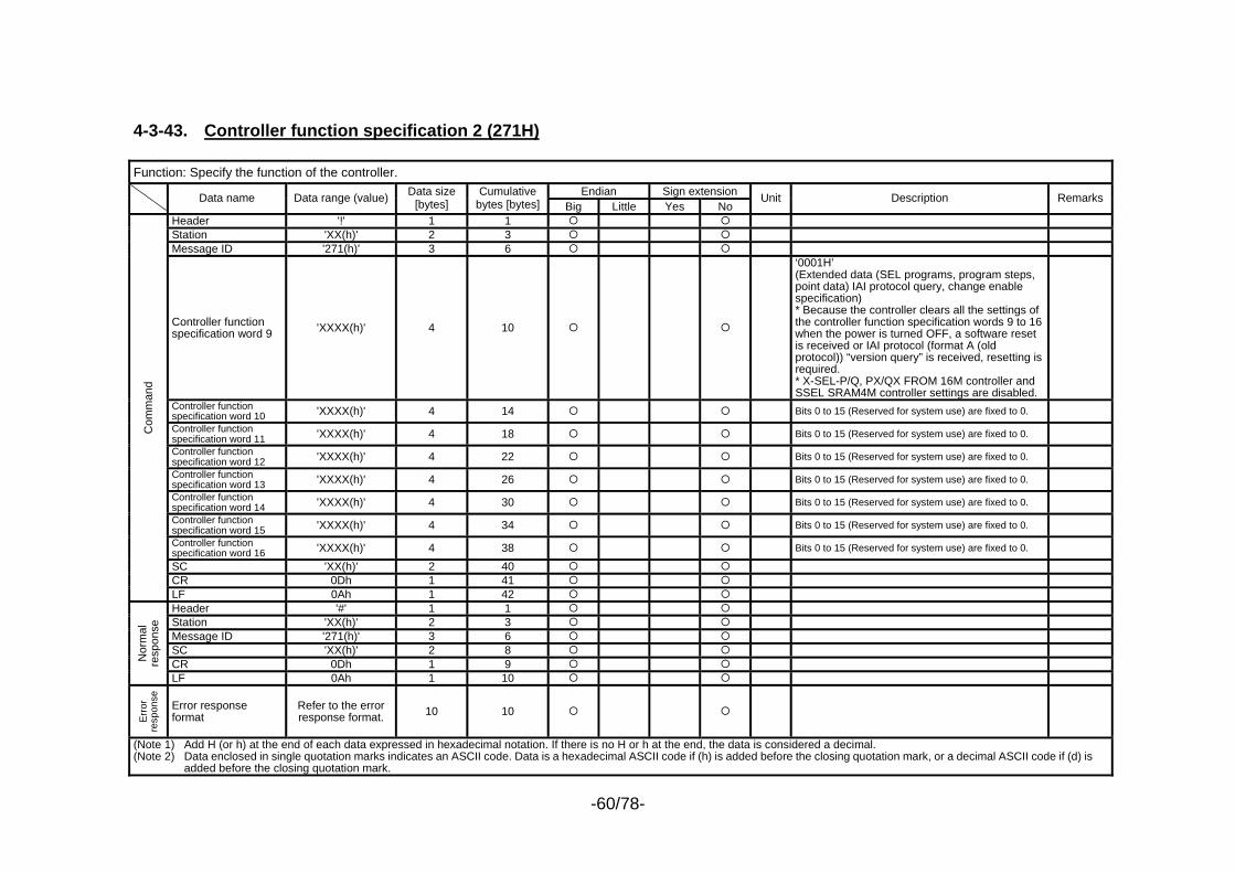
-60/78-
4-3-43. Controller function specification 2 (271H) Function: Specify the function of the controller.
Endian Sign extension Data name Data range (value) Data size [bytes]
Cumulative bytes [bytes] Big Little Yes No
Unit Description Remarks
Header '!' 1 1 Station 'XX(h)' 2 3 Message ID '271(h)' 3 6
Controller function specification word 9 'XXXX(h)' 4 10
‘0001H’ (Extended data (SEL programs, program steps, point data) IAI protocol query, change enable specification) * Because the controller clears all the settings of the controller function specification words 9 to 16 when the power is turned OFF, a software reset is received or IAI protocol (format A (old protocol)) “version query” is received, resetting is required. * X-SEL-P/Q, PX/QX FROM 16M controller and SSEL SRAM4M controller settings are disabled.
Controller function specification word 10 'XXXX(h)' 4 14 Bits 0 to 15 (Reserved for system use) are fixed to 0. Controller function specification word 11 'XXXX(h)' 4 18 Bits 0 to 15 (Reserved for system use) are fixed to 0. Controller function specification word 12 'XXXX(h)' 4 22 Bits 0 to 15 (Reserved for system use) are fixed to 0. Controller function specification word 13 'XXXX(h)' 4 26 Bits 0 to 15 (Reserved for system use) are fixed to 0. Controller function specification word 14 'XXXX(h)' 4 30 Bits 0 to 15 (Reserved for system use) are fixed to 0. Controller function specification word 15 'XXXX(h)' 4 34 Bits 0 to 15 (Reserved for system use) are fixed to 0. Controller function specification word 16 'XXXX(h)' 4 38 Bits 0 to 15 (Reserved for system use) are fixed to 0. SC 'XX(h)' 2 40 CR 0Dh 1 41
Com
man
d
LF 0Ah 1 42 Header '#' 1 1 Station 'XX(h)' 2 3 Message ID '271(h)' 3 6 SC 'XX(h)' 2 8 CR 0Dh 1 9 N
orm
al
resp
onse
LF 0Ah 1 10
Err
or
resp
onse
Error response format
Refer to the error response format. 10 10
(Note 1) Add H (or h) at the end of each data expressed in hexadecimal notation. If there is no H or h at the end, the data is considered a decimal. (Note 2) Data enclosed in single quotation marks indicates an ASCII code. Data is a hexadecimal ASCII code if (h) is added before the closing quotation mark, or a decimal ASCII code if (d) is
added before the closing quotation mark.
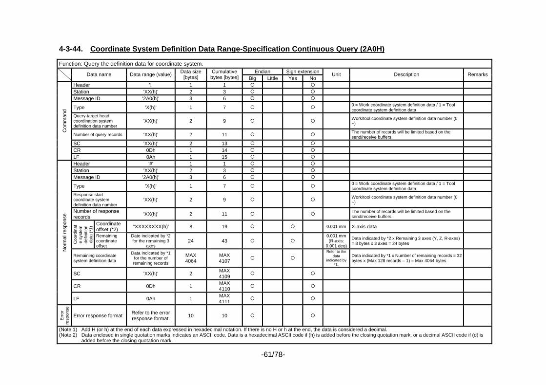
-61/78-
4-3-44. Coordinate System Definition Data Range-Specification Continuous Query (2A0H) Function: Query the definition data for coordinate system.
Endian Sign extension Data name Data range (value) Data size [bytes]
Cumulative bytes [bytes] Big Little Yes No
Unit Description Remarks
Header '!' 1 1 Station 'XX(h)' 2 3 Message ID '2A0(h)' 3 6
Type 'X(h)' 1 7 0 = Work coordinate system definition data / 1 = Tool coordinate system definition data
Query-target head coordination system definition data number
'XX(h)' 2 9 Work/tool coordinate system definition data number (0 ~)
Number of query records 'XX(h)' 2 11 The number of records will be limited based on the send/receive buffers.
SC 'XX(h)' 2 13 CR 0Dh 1 14
Com
man
d
LF 0Ah 1 15 Header '#' 1 1 Station 'XX(h)' 2 3 Message ID '2A0(h)' 3 6
Type 'X(h)' 1 7 0 = Work coordinate system definition data / 1 = Tool coordinate system definition data
Response start coordinate system definition data number
'XX(h)' 2 9 Work/tool coordinate system definition data number (0 ~)
Number of response records 'XX(h)' 2 11 The number of records will be limited based on the
send/receive buffers.
Coordinate offset (*2) ''XXXXXXXX(h)' 8 19 0.001 mm X-axis data
Coo
rdin
ate
syst
em
defin
ition
da
ta (*
1)
Remaining coordinate offset
Date indicated by *2 for the remaining 3
axes 24 43
0.001 mm (R-axis:
0.001 deg)
Data indicated by *2 x Remaining 3 axes (Y, Z, R-axes) = 8 bytes x 3 axes = 24 bytes
Remaining coordinate system definition data
Data indicated by *1 for the number of remaining records
MAX 4064
MAX 4107
Refer to the data
indicated by *1.
Data indicated by *1 x Number of remaining records = 32 bytes x (Max 128 records – 1) = Max 4064 bytes
SC 'XX(h)' 2 MAX 4109
CR 0Dh 1 MAX 4110
Nor
mal
resp
onse
LF 0Ah 1 MAX 4111
Err
or
resp
onse
Error response format Refer to the error response format. 10 10
(Note 1) Add H (or h) at the end of each data expressed in hexadecimal notation. If there is no H or h at the end, the data is considered a decimal. (Note 2) Data enclosed in single quotation marks indicates an ASCII code. Data is a hexadecimal ASCII code if (h) is added before the closing quotation mark, or a decimal ASCII code if (d) is
added before the closing quotation mark.
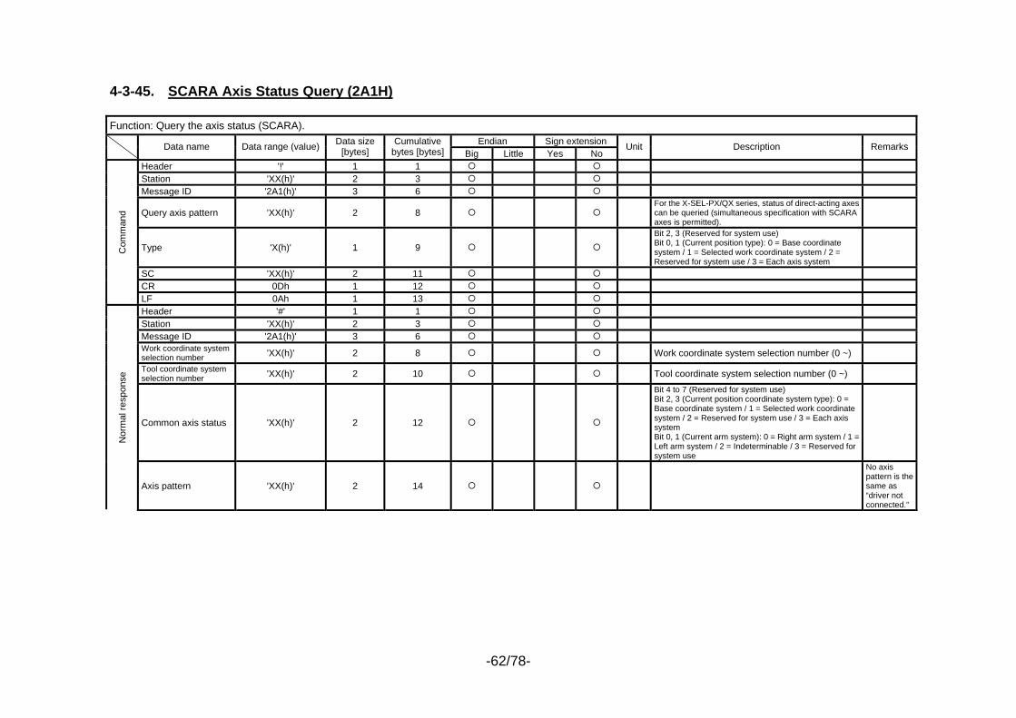
-62/78-
4-3-45. SCARA Axis Status Query (2A1H) Function: Query the axis status (SCARA).
Endian Sign extension Data name Data range (value) Data size [bytes]
Cumulative bytes [bytes] Big Little Yes No
Unit Description Remarks
Header '!' 1 1 Station 'XX(h)' 2 3 Message ID '2A1(h)' 3 6
Query axis pattern 'XX(h)' 2 8 For the X-SEL-PX/QX series, status of direct-acting axes can be queried (simultaneous specification with SCARA axes is permitted).
Type 'X(h)' 1 9 Bit 2, 3 (Reserved for system use) Bit 0, 1 (Current position type): 0 = Base coordinate system / 1 = Selected work coordinate system / 2 = Reserved for system use / 3 = Each axis system
SC 'XX(h)' 2 11 CR 0Dh 1 12
Com
man
d
LF 0Ah 1 13 Header '#' 1 1 Station 'XX(h)' 2 3 Message ID '2A1(h)' 3 6 Work coordinate system selection number 'XX(h)' 2 8 Work coordinate system selection number (0 ~) Tool coordinate system selection number 'XX(h)' 2 10 Tool coordinate system selection number (0 ~)
Common axis status 'XX(h)' 2 12
Bit 4 to 7 (Reserved for system use) Bit 2, 3 (Current position coordinate system type): 0 = Base coordinate system / 1 = Selected work coordinate system / 2 = Reserved for system use / 3 = Each axis system Bit 0, 1 (Current arm system): 0 = Right arm system / 1 = Left arm system / 2 = Indeterminable / 3 = Reserved for system use
Nor
mal
resp
onse
Axis pattern 'XX(h)' 2 14
No axis pattern is the same as “driver not connected.”
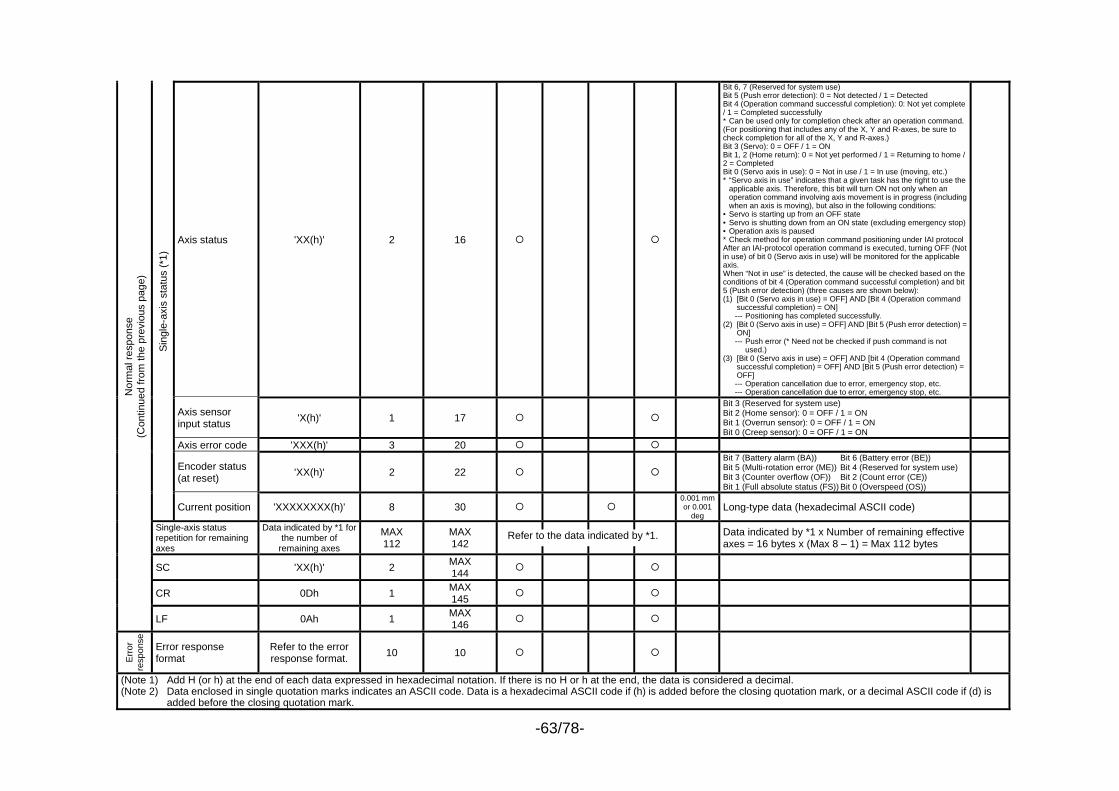
-63/78-
Axis status 'XX(h)' 2 16
Bit 6, 7 (Reserved for system use) Bit 5 (Push error detection): 0 = Not detected / 1 = Detected Bit 4 (Operation command successful completion): 0: Not yet complete / 1 = Completed successfully * Can be used only for completion check after an operation command. (For positioning that includes any of the X, Y and R-axes, be sure to check completion for all of the X, Y and R-axes.) Bit 3 (Servo): 0 = OFF / 1 = ON Bit 1, 2 (Home return): 0 = Not yet performed / 1 = Returning to home / 2 = Completed Bit 0 (Servo axis in use): 0 = Not in use / 1 = In use (moving, etc.) * “Servo axis in use” indicates that a given task has the right to use the
applicable axis. Therefore, this bit will turn ON not only when an operation command involving axis movement is in progress (including when an axis is moving), but also in the following conditions:
• Servo is starting up from an OFF state • Servo is shutting down from an ON state (excluding emergency stop)• Operation axis is paused * Check method for operation command positioning under IAI protocol After an IAI-protocol operation command is executed, turning OFF (Not in use) of bit 0 (Servo axis in use) will be monitored for the applicable axis. When “Not in use” is detected, the cause will be checked based on the conditions of bit 4 (Operation command successful completion) and bit 5 (Push error detection) (three causes are shown below): (1) [Bit 0 (Servo axis in use) = OFF] AND [Bit 4 (Operation command
successful completion) = ON] --- Positioning has completed successfully. (2) [Bit 0 (Servo axis in use) = OFF] AND [Bit 5 (Push error detection) =
ON] --- Push error (* Need not be checked if push command is not
used.) (3) [Bit 0 (Servo axis in use) = OFF] AND [bit 4 (Operation command
successful completion) = OFF] AND [Bit 5 (Push error detection) = OFF]
--- Operation cancellation due to error, emergency stop, etc. --- Operation cancellation due to error, emergency stop, etc.
Axis sensor input status 'X(h)' 1 17
Bit 3 (Reserved for system use) Bit 2 (Home sensor): 0 = OFF / 1 = ON Bit 1 (Overrun sensor): 0 = OFF / 1 = ON Bit 0 (Creep sensor): 0 = OFF / 1 = ON
Axis error code 'XXX(h)' 3 20
Encoder status (at reset) 'XX(h)' 2 22
Bit 7 (Battery alarm (BA)) Bit 6 (Battery error (BE)) Bit 5 (Multi-rotation error (ME)) Bit 4 (Reserved for system use) Bit 3 (Counter overflow (OF)) Bit 2 (Count error (CE)) Bit 1 (Full absolute status (FS)) Bit 0 (Overspeed (OS))
Sing
le-a
xis
stat
us (*
1)
Current position 'XXXXXXXX(h)' 8 30 0.001 mm or 0.001
deg Long-type data (hexadecimal ASCII code)
Single-axis status repetition for remaining axes
Data indicated by *1 for the number of
remaining axes
MAX 112
MAX 142
Data indicated by *1 x Number of remaining effective
axes = 16 bytes x (Max 8 – 1) = Max 112 bytes
SC 'XX(h)' 2 MAX 144
CR 0Dh 1 MAX 145
Nor
mal
resp
onse
(C
ontin
ued
from
the
prev
ious
pag
e)
LF 0Ah 1 MAX 146
Erro
r re
spon
se
Error response format
Refer to the error response format. 10 10
(Note 1) Add H (or h) at the end of each data expressed in hexadecimal notation. If there is no H or h at the end, the data is considered a decimal. (Note 2) Data enclosed in single quotation marks indicates an ASCII code. Data is a hexadecimal ASCII code if (h) is added before the closing quotation mark, or a decimal ASCII code if (d) is
added before the closing quotation mark.
Refer to the data indicated by *1.
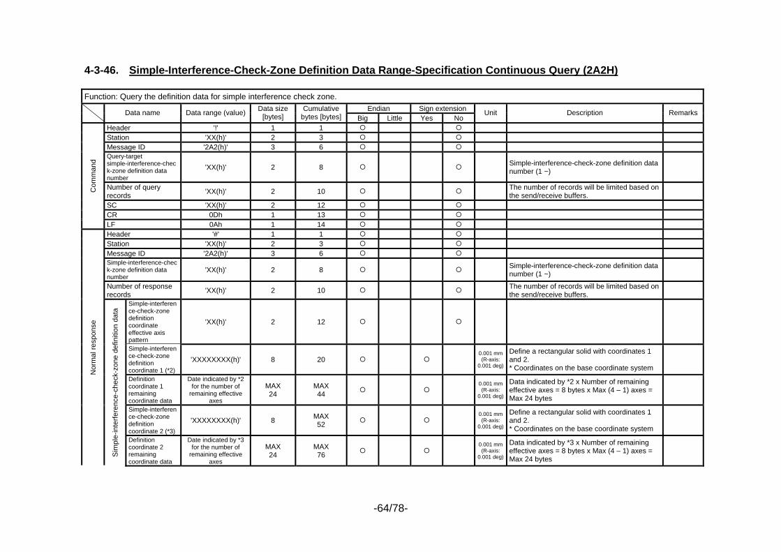
-64/78-
4-3-46. Simple-Interference-Check-Zone Definition Data Range-Specification Continuous Query (2A2H) Function: Query the definition data for simple interference check zone.
Endian Sign extension Data name Data range (value) Data size [bytes]
Cumulative bytes [bytes] Big Little Yes No
Unit Description Remarks
Header '!' 1 1 Station 'XX(h)' 2 3 Message ID '2A2(h)' 3 6 Query-target simple-interference-check-zone definition data number
'XX(h)' 2 8 Simple-interference-check-zone definition data number (1 ~)
Number of query records 'XX(h)' 2 10 The number of records will be limited based on
the send/receive buffers.
SC 'XX(h)' 2 12 CR 0Dh 1 13
Com
man
d
LF 0Ah 1 14 Header '#' 1 1 Station 'XX(h)' 2 3 Message ID '2A2(h)' 3 6 Simple-interference-check-zone definition data number
'XX(h)' 2 8 Simple-interference-check-zone definition data number (1 ~)
Number of response records 'XX(h)' 2 10 The number of records will be limited based on
the send/receive buffers.
Simple-interference-check-zone definition coordinate effective axis pattern
'XX(h)' 2 12
Simple-interference-check-zone definition coordinate 1 (*2)
'XXXXXXXX(h)' 8 20 0.001 mm (R-axis:
0.001 deg)
Define a rectangular solid with coordinates 1 and 2. * Coordinates on the base coordinate system
Definition coordinate 1 remaining coordinate data
Date indicated by *2 for the number of
remaining effective axes
MAX 24
MAX 44
0.001 mm (R-axis:
0.001 deg)
Data indicated by *2 x Number of remaining effective axes = 8 bytes x Max (4 – 1) axes = Max 24 bytes
Simple-interference-check-zone definition coordinate 2 (*3)
'XXXXXXXX(h)' 8 MAX 52
0.001 mm (R-axis:
0.001 deg)
Define a rectangular solid with coordinates 1 and 2. * Coordinates on the base coordinate system
Nor
mal
resp
onse
Sim
ple-
inte
rfere
nce-
chec
k-zo
ne d
efin
ition
dat
a
Definition coordinate 2 remaining coordinate data
Date indicated by *3 for the number of
remaining effective axes
MAX 24
MAX 76
0.001 mm (R-axis:
0.001 deg)
Data indicated by *3 x Number of remaining effective axes = 8 bytes x Max (4 – 1) axes = Max 24 bytes
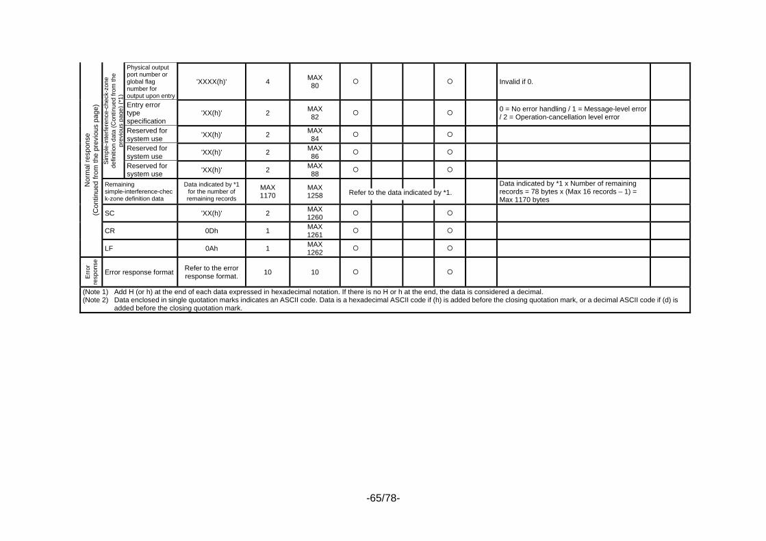
-65/78-
Physical output port number or global flag number for output upon entry
'XXXX(h)' 4 MAX 80 Invalid if 0.
Entry error type specification
'XX(h)' 2 MAX 82 0 = No error handling / 1 = Message-level error
/ 2 = Operation-cancellation level error
Reserved for system use 'XX(h)' 2 MAX
84
Reserved for system use 'XX(h)' 2 MAX
86
Sim
ple-
inte
rfere
nce-
chec
k-zo
ne
defin
ition
dat
a (C
ontin
ued
from
the
prev
ious
pag
e) (*
1)
Reserved for system use 'XX(h)' 2 MAX
88
Remaining simple-interference-check-zone definition data
Data indicated by *1 for the number of remaining records
MAX 1170
MAX 1258
Data indicated by *1 x Number of remaining records = 78 bytes x (Max 16 records – 1) = Max 1170 bytes
SC 'XX(h)' 2 MAX 1260
CR 0Dh 1 MAX 1261
Nor
mal
resp
onse
(C
ontin
ued
from
the
prev
ious
pag
e)
LF 0Ah 1 MAX 1262
Err
or
resp
onse
Error response format Refer to the error response format. 10 10
(Note 1) Add H (or h) at the end of each data expressed in hexadecimal notation. If there is no H or h at the end, the data is considered a decimal. (Note 2) Data enclosed in single quotation marks indicates an ASCII code. Data is a hexadecimal ASCII code if (h) is added before the closing quotation mark, or a decimal ASCII code if (d) is
added before the closing quotation mark.
Refer to the data indicated by *1.
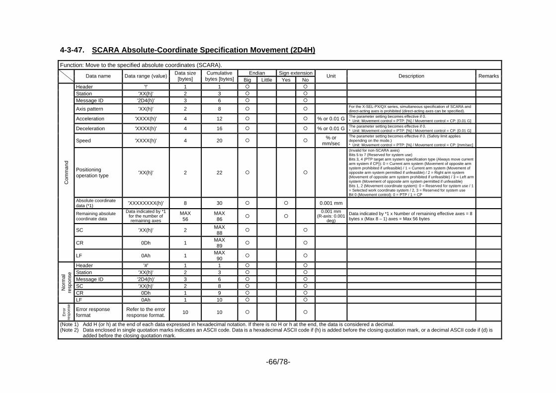
-66/78-
4-3-47. SCARA Absolute-Coordinate Specification Movement (2D4H) Function: Move to the specified absolute coordinates (SCARA).
Endian Sign extension Data name Data range (value) Data size [bytes]
Cumulative bytes [bytes] Big Little Yes No
Unit Description Remarks
Header '!' 1 1 Station 'XX(h)' 2 3 Message ID '2D4(h)' 3 6 Axis pattern 'XX(h)' 2 8 For the X-SEL-PX/QX series, simultaneous specification of SCARA and
direct-acting axes is prohibited (direct-acting axes can be specified).
Acceleration 'XXXX(h)' 4 12 % or 0.01 G The parameter setting becomes effective if 0. * Unit: Movement control = PTP: [%] / Movement control = CP: [0.01 G]
Deceleration 'XXXX(h)' 4 16 % or 0.01 G The parameter setting becomes effective if 0. * Unit: Movement control = PTP: [%] / Movement control = CP: [0.01 G]
Speed 'XXXX(h)' 4 20 % or mm/sec
The parameter setting becomes effective if 0. (Safety limit applies depending on the mode.) * Unit: Movement control = PTP: [%] / Movement control = CP: [mm/sec]
Positioning operation type 'XX(h)' 2 22
(Invalid for non-SCARA axes) Bits 5 to 7 (Reserved for system use) Bits 3, 4 (PTP target arm system specification type (Always move current arm system if CP)): 0 = Current arm system (Movement of opposite arm system prohibited if unfeasible) / 1 = Current arm system (Movement of opposite arm system permitted if unfeasible) / 2 = Right arm system (Movement of opposite arm system prohibited if unfeasible) / 3 = Left arm system (Movement of opposite arm system permitted if unfeasible) Bits 1, 2 (Movement coordinate system): 0 = Reserved for system use / 1 = Selected work coordinate system / 2, 3 = Reserved for system use Bit 0 (Movement control): 0 = PTP / 1 = CP
Absolute coordinate data (*1) 'XXXXXXXX(h)' 8 30 0.001 mm
Remaining absolute coordinate data
Data indicated by *1 for the number of remaining axes
MAX 56
MAX 86
0.001 mm (R-axis: 0.001
deg) Data indicated by *1 x Number of remaining effective axes = 8 bytes x (Max 8 – 1) axes = Max 56 bytes
SC 'XX(h)' 2 MAX 88
CR 0Dh 1 MAX 89
Com
man
d
LF 0Ah 1 MAX 90
Header '#' 1 1 Station 'XX(h)' 2 3 Message ID '2D4(h)' 3 6 SC 'XX(h)' 2 8 CR 0Dh 1 9
Nor
mal
re
spon
se
LF 0Ah 1 10
Erro
r re
spon
se
Error response format
Refer to the error response format. 10 10
(Note 1) Add H (or h) at the end of each data expressed in hexadecimal notation. If there is no H or h at the end, the data is considered a decimal. (Note 2) Data enclosed in single quotation marks indicates an ASCII code. Data is a hexadecimal ASCII code if (h) is added before the closing quotation mark, or a decimal ASCII code if (d) is
added before the closing quotation mark.
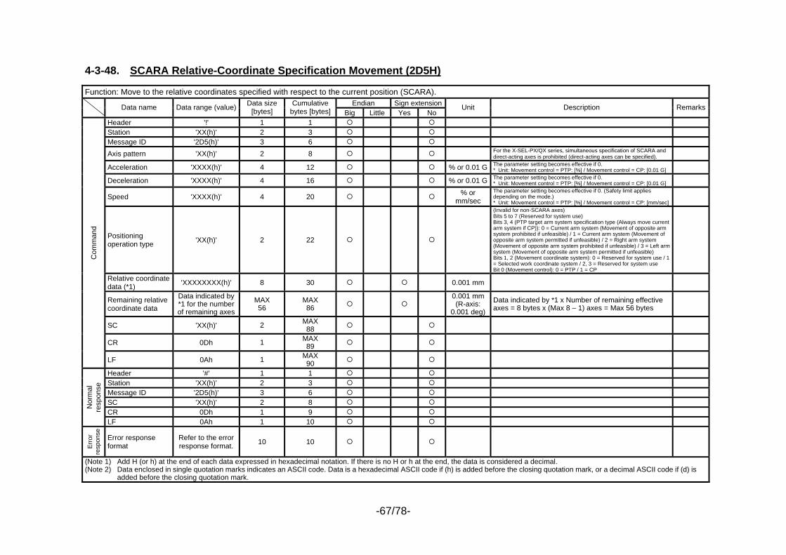
-67/78-
4-3-48. SCARA Relative-Coordinate Specification Movement (2D5H) Function: Move to the relative coordinates specified with respect to the current position (SCARA).
Endian Sign extension Data name Data range (value) Data size [bytes]
Cumulative bytes [bytes] Big Little Yes No
Unit Description Remarks
Header '!' 1 1 Station 'XX(h)' 2 3 Message ID '2D5(h)' 3 6 Axis pattern 'XX(h)' 2 8 For the X-SEL-PX/QX series, simultaneous specification of SCARA and
direct-acting axes is prohibited (direct-acting axes can be specified).
Acceleration 'XXXX(h)' 4 12 % or 0.01 G The parameter setting becomes effective if 0. * Unit: Movement control = PTP: [%] / Movement control = CP: [0.01 G]
Deceleration 'XXXX(h)' 4 16 % or 0.01 G The parameter setting becomes effective if 0. * Unit: Movement control = PTP: [%] / Movement control = CP: [0.01 G]
Speed 'XXXX(h)' 4 20 % or mm/sec
The parameter setting becomes effective if 0. (Safety limit applies depending on the mode.) * Unit: Movement control = PTP: [%] / Movement control = CP: [mm/sec]
Positioning operation type 'XX(h)' 2 22
(Invalid for non-SCARA axes) Bits 5 to 7 (Reserved for system use) Bits 3, 4 (PTP target arm system specification type (Always move current arm system if CP)): 0 = Current arm system (Movement of opposite arm system prohibited if unfeasible) / 1 = Current arm system (Movement of opposite arm system permitted if unfeasible) / 2 = Right arm system (Movement of opposite arm system prohibited if unfeasible) / 3 = Left arm system (Movement of opposite arm system permitted if unfeasible) Bits 1, 2 (Movement coordinate system): 0 = Reserved for system use / 1 = Selected work coordinate system / 2, 3 = Reserved for system use Bit 0 (Movement control): 0 = PTP / 1 = CP
Relative coordinate data (*1) 'XXXXXXXX(h)' 8 30 0.001 mm
Remaining relative coordinate data
Data indicated by *1 for the number of remaining axes
MAX 56
MAX 86
0.001 mm (R-axis:
0.001 deg) Data indicated by *1 x Number of remaining effective axes = 8 bytes x (Max 8 – 1) axes = Max 56 bytes
SC 'XX(h)' 2 MAX 88
CR 0Dh 1 MAX 89
Com
man
d
LF 0Ah 1 MAX 90
Header '#' 1 1 Station 'XX(h)' 2 3 Message ID '2D5(h)' 3 6 SC 'XX(h)' 2 8 CR 0Dh 1 9
Nor
mal
re
spon
se
LF 0Ah 1 10
Erro
r re
spon
se
Error response format
Refer to the error response format. 10 10
(Note 1) Add H (or h) at the end of each data expressed in hexadecimal notation. If there is no H or h at the end, the data is considered a decimal. (Note 2) Data enclosed in single quotation marks indicates an ASCII code. Data is a hexadecimal ASCII code if (h) is added before the closing quotation mark, or a decimal ASCII code if (d) is
added before the closing quotation mark.

-68/78-
4-3-49. SCARA Point-Number Specification Movement (2D6H) Function: Move to the specified point number (SCARA).
Endian Sign extension Data name Data range (value) Data size [bytes]
Cumulative bytes [bytes] Big Little Yes No
Unit Description Remarks
Header '!' 1 1 Station 'XX(h)' 2 3 Message ID '2D6(h)' 3 6
Axis pattern 'XX(h)' 2 8 Used by an AND condition with the axis pattern of the point number. For the X-SEL-PX/QX series, simultaneous specification of SCARA and direct-acting axes is prohibited (direct-acting axes can be specified).
Acceleration 'XXXX(h)' 4 12 % or 0.01 GThe applicable setting in the position data becomes effective if zero. If both are zero, the parameter setting is followed. * Unit: Movement control = PTP: [%] / Movement control = CP: [0.01 G]
Deceleration 'XXXX(h)' 4 16 % or 0.01 GThe applicable setting in the position data becomes effective if zero. If both are zero, the parameter setting is followed. * Unit: Movement control = PTP: [%] / Movement control = CP: [0.01 G]
Speed 'XXXX(h)' 4 20 % or mm/sec
The applicable setting in the position data becomes effective if zero. If both are zero, the parameter setting is followed. (Safety limit applies depending on the mode.) * Unit: Movement control = PTP: [%] / Movement control = CP: mm/sec
Positioning operation type 'XX(h)' 2 22
(Invalid for non-SCARA axes) Bits 5 to 7 (Reserved for system use) are fixed to 0. Bits 3, 4 (PTP target arm system specification type (Always move current arm system if CP)): 0 = Current arm system (Movement of opposite arm system prohibited if unfeasible) / 1 = Current arm system (Movement of opposite arm system permitted if unfeasible) / 2 = Right arm system (Movement of opposite arm system prohibited if unfeasible) / 3 = Left arm system (Movement of opposite arm system permitted if unfeasible) Bits 1, 2 (Movement coordinate system): 0 = Reserved for system use / 1 = Selected work coordinate system / 2, 3 = Reserved for system use Bit 0 (Movement control): 0 = PTP / 1 = CP
Point number 'XXX(h)' 3 25 SC 'XX(h)' 2 27 CR 0Dh 1 28
Com
man
d
LF 0Ah 1 29 Header '#' 1 1 Station 'XX(h)' 2 3 Message ID '2D6(h)' 3 6 SC 'XX(h)' 2 8 CR 0Dh 1 9
Nor
mal
re
spon
se
LF 0Ah 1 10
Err
or
resp
onse
Error response format
Refer to the error response format. 10 10
(Note 1) Add H (or h) at the end of each data expressed in hexadecimal notation. If there is no H or h at the end, the data is considered a decimal. (Note 2) Data enclosed in single quotation marks indicates an ASCII code. Data is a hexadecimal ASCII code if (h) is added before the closing quotation mark, or a decimal ASCII code if (d) is
added before the closing quotation mark.
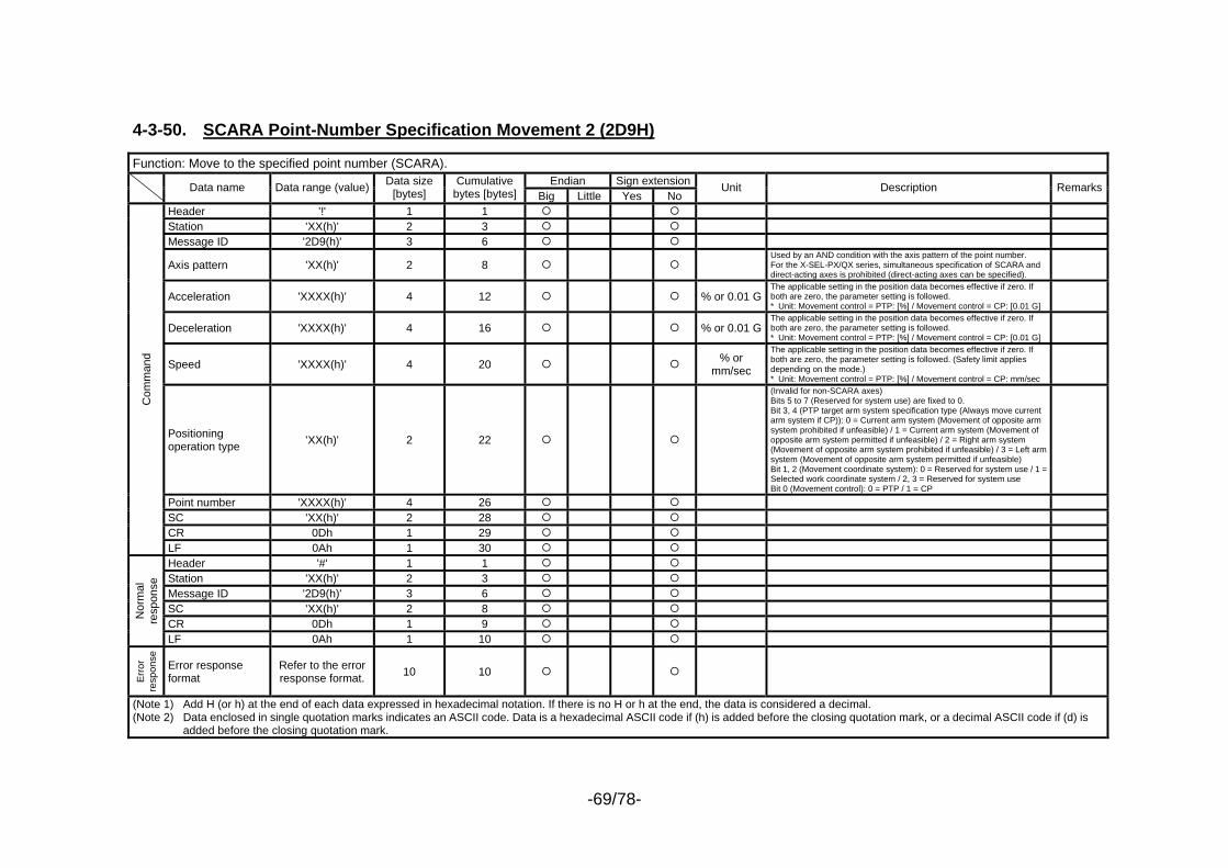
-69/78-
4-3-50. SCARA Point-Number Specification Movement 2 (2D9H) Function: Move to the specified point number (SCARA).
Endian Sign extension Data name Data range (value) Data size [bytes]
Cumulative bytes [bytes] Big Little Yes No
Unit Description Remarks
Header '!' 1 1 Station 'XX(h)' 2 3 Message ID '2D9(h)' 3 6
Axis pattern 'XX(h)' 2 8 Used by an AND condition with the axis pattern of the point number. For the X-SEL-PX/QX series, simultaneous specification of SCARA and direct-acting axes is prohibited (direct-acting axes can be specified).
Acceleration 'XXXX(h)' 4 12 % or 0.01 GThe applicable setting in the position data becomes effective if zero. If both are zero, the parameter setting is followed. * Unit: Movement control = PTP: [%] / Movement control = CP: [0.01 G]
Deceleration 'XXXX(h)' 4 16 % or 0.01 GThe applicable setting in the position data becomes effective if zero. If both are zero, the parameter setting is followed. * Unit: Movement control = PTP: [%] / Movement control = CP: [0.01 G]
Speed 'XXXX(h)' 4 20 % or mm/sec
The applicable setting in the position data becomes effective if zero. If both are zero, the parameter setting is followed. (Safety limit applies depending on the mode.) * Unit: Movement control = PTP: [%] / Movement control = CP: mm/sec
Positioning operation type 'XX(h)' 2 22
(Invalid for non-SCARA axes) Bits 5 to 7 (Reserved for system use) are fixed to 0. Bit 3, 4 (PTP target arm system specification type (Always move current arm system if CP)): 0 = Current arm system (Movement of opposite arm system prohibited if unfeasible) / 1 = Current arm system (Movement of opposite arm system permitted if unfeasible) / 2 = Right arm system (Movement of opposite arm system prohibited if unfeasible) / 3 = Left arm system (Movement of opposite arm system permitted if unfeasible) Bit 1, 2 (Movement coordinate system): 0 = Reserved for system use / 1 = Selected work coordinate system / 2, 3 = Reserved for system use Bit 0 (Movement control): 0 = PTP / 1 = CP
Point number 'XXXX(h)' 4 26 SC 'XX(h)' 2 28 CR 0Dh 1 29
Com
man
d
LF 0Ah 1 30 Header '#' 1 1 Station 'XX(h)' 2 3 Message ID '2D9(h)' 3 6 SC 'XX(h)' 2 8 CR 0Dh 1 9
Nor
mal
re
spon
se
LF 0Ah 1 10
Err
or
resp
onse
Error response format
Refer to the error response format. 10 10
(Note 1) Add H (or h) at the end of each data expressed in hexadecimal notation. If there is no H or h at the end, the data is considered a decimal. (Note 2) Data enclosed in single quotation marks indicates an ASCII code. Data is a hexadecimal ASCII code if (h) is added before the closing quotation mark, or a decimal ASCII code if (d) is
added before the closing quotation mark.
-70/78-
5. Timeout and Retry The normal responses and error responses received by the master station (host) from the slave station (controller) must satisfy all of the following conditions:
(1) The normal response or error response format is satisfied. (2) The checksum (SC) is correct. (3) The station number in the transmitted command is the same as the station number in the reception response. (4) The message ID in the transmitted command is the same as the message ID in the reception response (except in the
case of error response). If completion of reception of a normal response or error response that satisfies the above conditions cannot be confirmed within a specified period (3 seconds) after completion of command transmission, the master station (host) will attempt to restore communication via command retransmission (retry transmission). When the number of retry transmissions exceeds the upper limit (2 or 3, selected in accordance with the system), the system shall recognize an irrecoverable communication error.
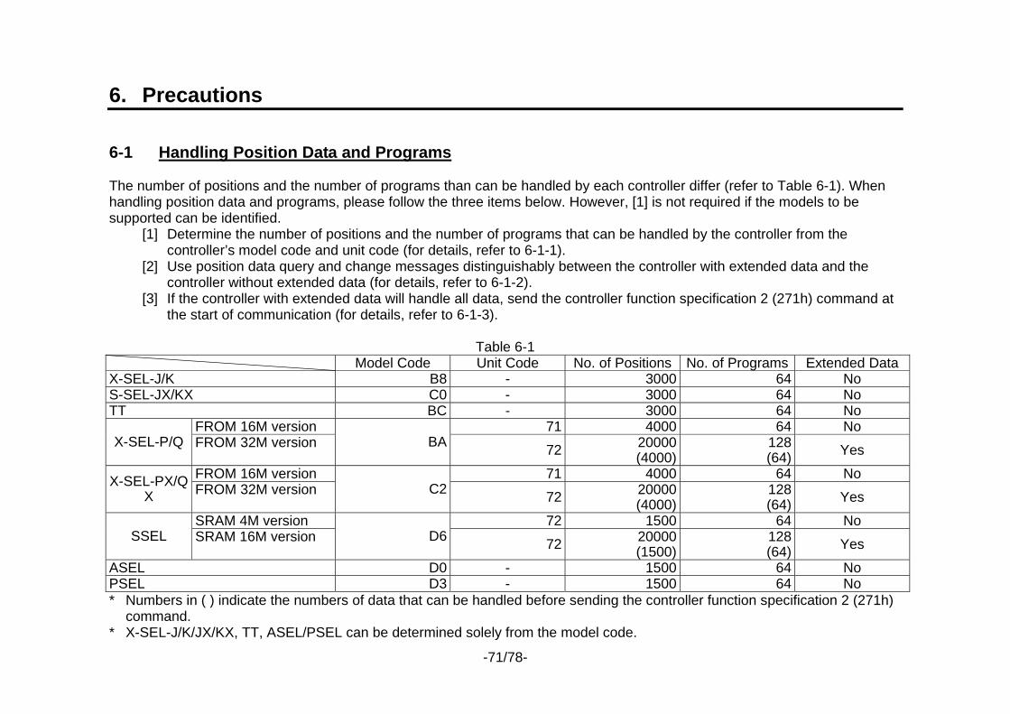
-71/78-
6. Precautions 6-1 Handling Position Data and Programs The number of positions and the number of programs than can be handled by each controller differ (refer to Table 6-1). When handling position data and programs, please follow the three items below. However, [1] is not required if the models to be supported can be identified.
[1] Determine the number of positions and the number of programs that can be handled by the controller from the controller’s model code and unit code (for details, refer to 6-1-1).
[2] Use position data query and change messages distinguishably between the controller with extended data and the controller without extended data (for details, refer to 6-1-2).
[3] If the controller with extended data will handle all data, send the controller function specification 2 (271h) command at the start of communication (for details, refer to 6-1-3).
Table 6-1
Model Code Unit Code No. of Positions No. of Programs Extended Data X-SEL-J/K B8 - 3000 64 No S-SEL-JX/KX C0 - 3000 64 No TT BC - 3000 64 No
FROM 16M version 71 4000 64 No X-SEL-P/Q FROM 32M version BA 72 20000
(4000)128(64) Yes
FROM 16M version 71 4000 64 No X-SEL-PX/QX FROM 32M version C2 72 20000
(4000)128(64) Yes
SRAM 4M version 72 1500 64 No SSEL SRAM 16M version D6 72 20000
(1500)128(64) Yes
ASEL D0 - 1500 64 No PSEL D3 - 1500 64 No * Numbers in ( ) indicate the numbers of data that can be handled before sending the controller function specification 2 (271h)
command. * X-SEL-J/K/JX/KX, TT, ASEL/PSEL can be determined solely from the model code.
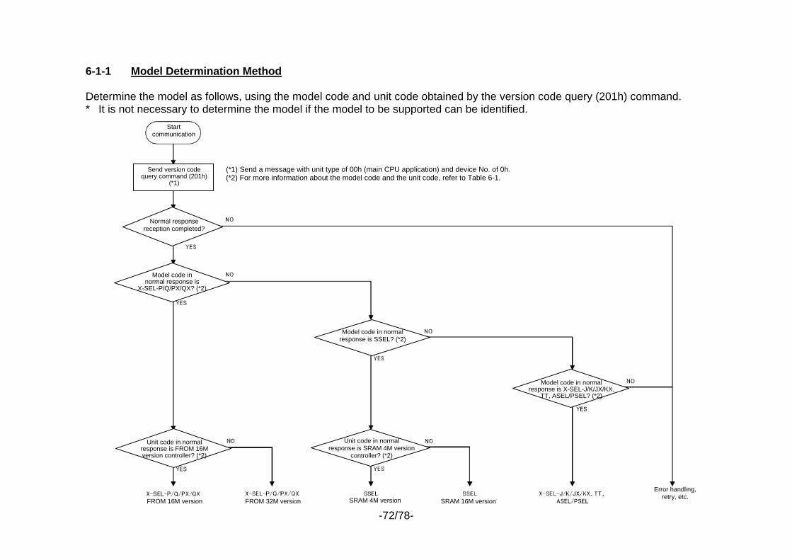
-72/78-
6-1-1 Model Determination Method Determine the model as follows, using the model code and unit code obtained by the version code query (201h) command. * It is not necessary to determine the model if the model to be supported can be identified.
Start communication
Normal response reception completed?
Send version code query command (201h)
(*1)
Model code in normal response is
X-SEL-P/Q/PX/QX? (*2)
Unit code in normal response is FROM 16M version controller? (*2)
(*1) Send a message with unit type of 00h (main CPU application) and device No. of 0h.(*2) For more information about the model code and the unit code, refer to Table 6-1.
Model code in normal response is SSEL? (*2)
Unit code in normal response is SRAM 4M version
controller? (*2)
Model code in normal response is X-SEL-J/K/JX/KX,
TT, ASEL/PSEL? (*2)
Error handling, retry, etc.
FROM 16M version FROM 32M version SRAM 4M version SRAM 16M version
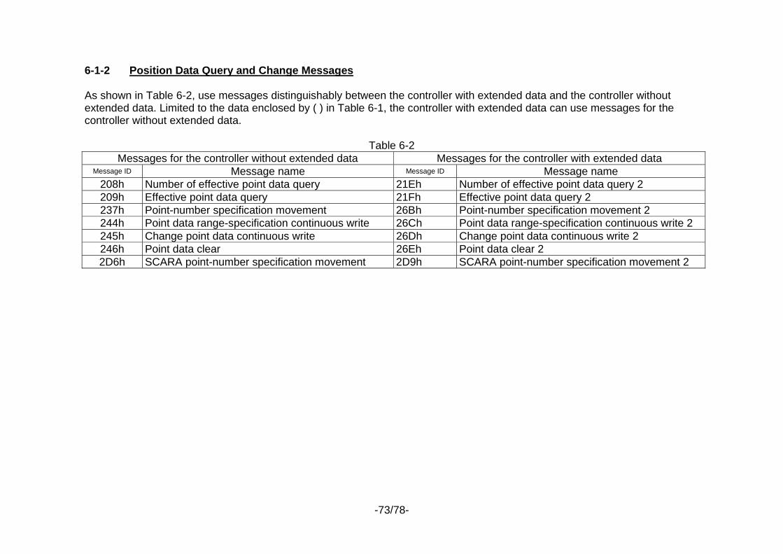
-73/78-
6-1-2 Position Data Query and Change Messages As shown in Table 6-2, use messages distinguishably between the controller with extended data and the controller without extended data. Limited to the data enclosed by ( ) in Table 6-1, the controller with extended data can use messages for the controller without extended data.
Table 6-2 Messages for the controller without extended data Messages for the controller with extended data
Message ID Message name Message ID Message name 208h Number of effective point data query 21Eh Number of effective point data query 2 209h Effective point data query 21Fh Effective point data query 2 237h Point-number specification movement 26Bh Point-number specification movement 2 244h Point data range-specification continuous write 26Ch Point data range-specification continuous write 2 245h Change point data continuous write 26Dh Change point data continuous write 2 246h Point data clear 26Eh Point data clear 2 2D6h SCARA point-number specification movement 2D9h SCARA point-number specification movement 2
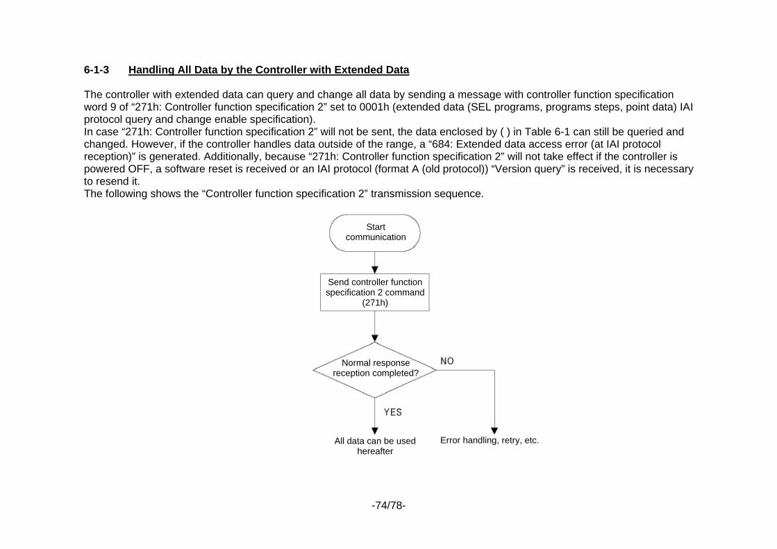
-74/78-
6-1-3 Handling All Data by the Controller with Extended Data The controller with extended data can query and change all data by sending a message with controller function specification word 9 of “271h: Controller function specification 2” set to 0001h (extended data (SEL programs, programs steps, point data) IAI protocol query and change enable specification). In case “271h: Controller function specification 2” will not be sent, the data enclosed by ( ) in Table 6-1 can still be queried and changed. However, if the controller handles data outside of the range, a “684: Extended data access error (at IAI protocol reception)” is generated. Additionally, because “271h: Controller function specification 2” will not take effect if the controller is powered OFF, a software reset is received or an IAI protocol (format A (old protocol)) “Version query” is received, it is necessary to resend it. The following shows the “Controller function specification 2” transmission sequence.
Send controller function specification 2 command
(271h)
All data can be used hereafter
Error handling, retry, etc.
Start communication
Normal response reception completed?
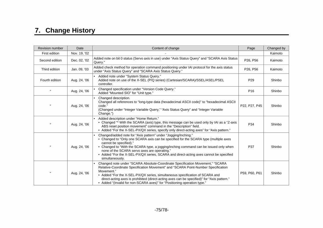
-75/78-
7. Change History
Revision number Date Content of change Page Changed by First edition Nov. 19, '02 - Kaimoto
Second edition Dec. 02, '02 Added note on bit 0 status (Servo axis in use) under “Axis Status Query” and “SCARA Axis Status Query.” P26, P56 Kaimoto
Third edition Jan. 09, '03 Added check method for operation command positioning under IAI protocol for the axis status under “Axis Status Query” and “SCARA Axis Status Query.” P26, P56 Kaimoto
Fourth edition Aug. 24, '06 • Added note under “System Status Query.”
Added note on use of the X-SEL (P/Q series) (Cartesian/SCARA)/SSEL/ASEL/PSEL controller.
P29 Shinbo
″ Aug. 24, '06 • Changed specification under “Version Code Query.” Added “Mounted SIO” for “Unit type.” P16 Shinbo
″ Aug. 24, '06
• Changed description. Changed all references to “long-type data (hexadecimal ASCII code)” to “hexadecimal ASCII code.” (Changed under “Integer Variable Query,” “Axis Status Query” and “Integer Variable Change.”)
P22, P27, P45 Shinbo
″ Aug. 24, '06
• Added description under “Home Return.” • Changed “* With the SCARA (axis) type, this message can be used only by IAI as a “Z-axis
ABS reset position movement” command in the “Description” field. • Added “For the X-SEL-PX/QX series, specify only direct-acting axes” for “Axis pattern.”
P34 Shinbo
″ Aug. 24, '06
• Changed/added note for “Axis pattern” under “Jogging/Inching.” • Changed to “Only one SCARA axis can be specified for the SCARA type (multiple axes
cannot be specified).” • Changed to “With the SCARA type, a jogging/inching command can be issued only when
none of the SCARA servo axes are operating.” • Added “For the X-SEL-PX/QX series, SCARA and direct-acting axes cannot be specified
simultaneously.
P37 Shinbo
″ Aug. 24, '06
• Changed note under “SCARA Absolute-Coordinate Specification Movement,” “SCARA Relative-Coordinate Specification Movement” and “SCARA Point-Number Specification Movement.” • Added “For the X-SEL-PX/QX series, simultaneous specification of SCARA and
direct-acting axes is prohibited (direct-acting axes can be specified)” for “Axis pattern.” • Added “(Invalid for non-SCARA axes)” for “Positioning operation type.”
P59, P60, P61 Shinbo
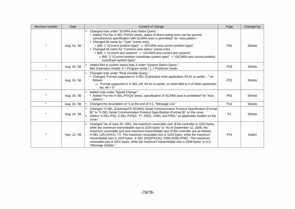
-76/78-
Revision number Date Content of change Page Changed by
″ Aug. 24, '06
• Changed note under “SCARA Axis Status Query.” • Added “For the X-SEL-PX/QX series, status of direct-acting axes can be queried
(simultaneous specification with SCARA axes is permitted)” for “Axis pattern.” • Changed bit name for “Type” (name only).
• Bit0, 1 “(Current position type)” → “(SCARA-axis current position type)” • Changed bit name for “Common axis status” (name only).
• Bit0, 1 “(Current arm system)” → “(SCARA-axis current arm system)” • Bit2, 3 “(Current position coordinate system type)” → “(SCARA-axis current position
coordinate system type)”
P55 Shinbo
″ Aug. 24, '06 • Added Bit4 to system status byte 3 under “System Status Query.” Bit4 (Operation mode): 0 = Program mode / 1 = Positioner mode P29 Shinbo
″ Aug. 24, '06
• Changed note under “Real Variable Query.” • Changed “Format supported in X-SEL (Cartesian) main application V0.41 or earlier…” as
follows: → “Format supported in X-SEL-J/K V0.41 or earlier, or when Bit0 to 3 of Other parameter
No. 46 = 0”
P23 Shinbo
″ Aug. 24, '06 • Added note under “Speed Change.”
• Added “For the X-SEL-PX/QX series, specification of SCARA axes is prohibited” for “Axis pattern.”
P53 Shinbo
″ Aug. 24, '06 • Changed the description of *1 at the end of 4-1, “Message List.” P13 Shinbo
″ Aug. 24, '06
• Changed “X-SEL (Cartesian/IX SCARA) Serial Communication Protocol Specification (Format B)” to “X-SEL Serial Communication Protocol Specification (Format B)” on the cover.
• Added “X-SEL-P/Q, X-SEL-PX/QX, TT, SSEL, ASEL and PSEL” as applicable models on the cover.
P1 Shinbo
″ Sep. 12, '06
• Changed “As of June 26, 2001, the maximum receivable size of the controller is 1023 bytes, while the maximum transmittable size is 1024 bytes” to “As of September 12, 2006, the maximum receivable size and maximum transmittable size of the controller are as follows: X-SEL (J/K/JX/KX), TT: The maximum receivable size is 1023 bytes, while the maximum transmittable size is 1024 bytes. X-SEL (P/Q/PX/QX), SSEL/ASEL/PSEL: The maximum receivable size is 2051 bytes, while the maximum transmittable size is 2048 bytes” in 4-3, “Message Details.”
P14 Iwakiri
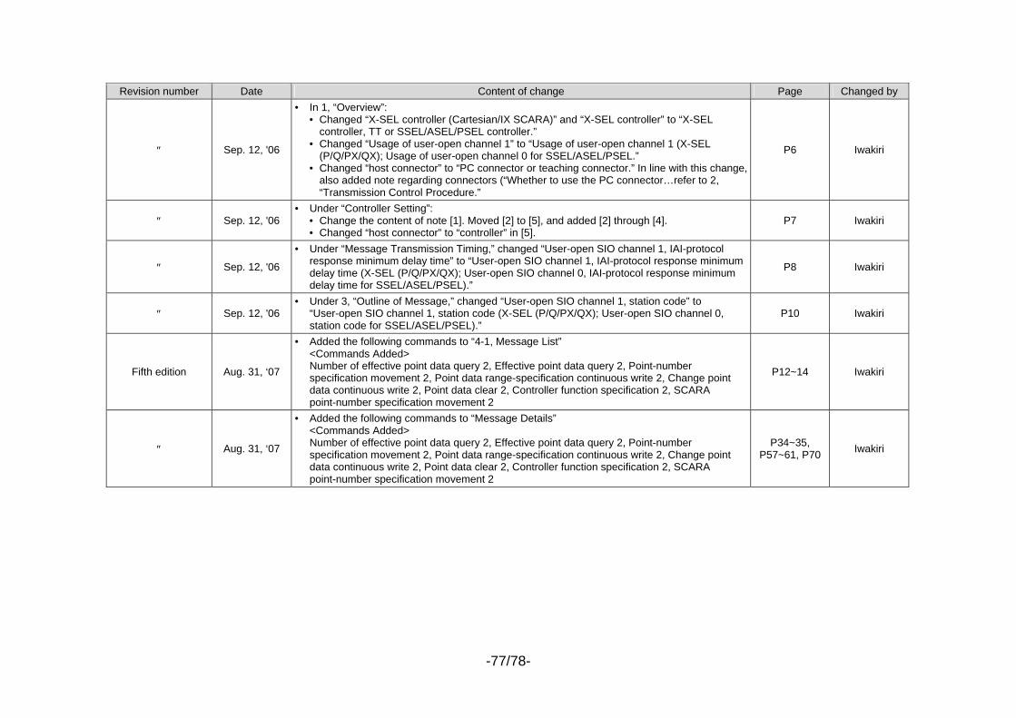
-77/78-
Revision number Date Content of change Page Changed by
″ Sep. 12, '06
• In 1, “Overview”: • Changed “X-SEL controller (Cartesian/IX SCARA)” and “X-SEL controller” to “X-SEL
controller, TT or SSEL/ASEL/PSEL controller.” • Changed “Usage of user-open channel 1” to “Usage of user-open channel 1 (X-SEL
(P/Q/PX/QX); Usage of user-open channel 0 for SSEL/ASEL/PSEL.” • Changed “host connector” to “PC connector or teaching connector.” In line with this change,
also added note regarding connectors (“Whether to use the PC connector…refer to 2, “Transmission Control Procedure.”
P6 Iwakiri
″ Sep. 12, '06 • Under “Controller Setting”:
• Change the content of note [1]. Moved [2] to [5], and added [2] through [4]. • Changed “host connector” to “controller” in [5].
P7 Iwakiri
″ Sep. 12, '06
• Under “Message Transmission Timing,” changed “User-open SIO channel 1, IAI-protocol response minimum delay time” to “User-open SIO channel 1, IAI-protocol response minimum delay time (X-SEL (P/Q/PX/QX); User-open SIO channel 0, IAI-protocol response minimum delay time for SSEL/ASEL/PSEL).”
P8 Iwakiri
″ Sep. 12, '06 • Under 3, “Outline of Message,” changed “User-open SIO channel 1, station code” to
“User-open SIO channel 1, station code (X-SEL (P/Q/PX/QX); User-open SIO channel 0, station code for SSEL/ASEL/PSEL).”
P10 Iwakiri
Fifth edition Aug. 31, ‘07
• Added the following commands to “4-1, Message List” <Commands Added> Number of effective point data query 2, Effective point data query 2, Point-number specification movement 2, Point data range-specification continuous write 2, Change point data continuous write 2, Point data clear 2, Controller function specification 2, SCARA point-number specification movement 2
P12~14 Iwakiri
″ Aug. 31, ‘07
• Added the following commands to “Message Details” <Commands Added> Number of effective point data query 2, Effective point data query 2, Point-number specification movement 2, Point data range-specification continuous write 2, Change point data continuous write 2, Point data clear 2, Controller function specification 2, SCARA point-number specification movement 2
P34~35, P57~61, P70 Iwakiri
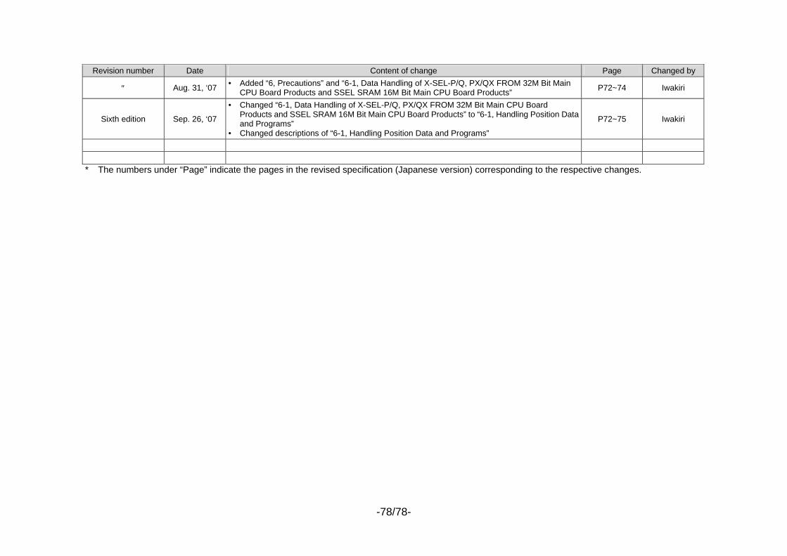
-78/78-
Revision number Date Content of change Page Changed by
″ Aug. 31, ‘07 • Added “6, Precautions” and “6-1, Data Handling of X-SEL-P/Q, PX/QX FROM 32M Bit Main CPU Board Products and SSEL SRAM 16M Bit Main CPU Board Products” P72~74 Iwakiri
Sixth edition Sep. 26, ‘07
• Changed “6-1, Data Handling of X-SEL-P/Q, PX/QX FROM 32M Bit Main CPU Board Products and SSEL SRAM 16M Bit Main CPU Board Products” to “6-1, Handling Position Data and Programs”
• Changed descriptions of “6-1, Handling Position Data and Programs”
P72~75 Iwakiri
* The numbers under “Page” indicate the pages in the revised specification (Japanese version) corresponding to the respective changes.