X-SEL Controller PX/QX Type - Delta Elektronik · X-SEL Controller PX/QX Type. CAUTION ... z...
471
Operation Manual First Edition X-SEL Controller PX/QX Type
Transcript of X-SEL Controller PX/QX Type - Delta Elektronik · X-SEL Controller PX/QX Type. CAUTION ... z...

Operation Manual First Edition
X-SEL ControllerPX/QX Type

CAUTION
Operator Alarm on Low Battery Voltage This controller is equipped with the following backup batteries for retention of data in the event of power failure:
[1] System-memory backup battery For retention of position data, global variables/flags, error list, strings, etc. [2] Absolute encoder backup battery
For retention of encoder rotation data. Since these batteries are not rechargeable, they will eventually be consumed. Unless the batteries are replaced in a timely manner, the voltage will drop to a level where the data can no longer be retained. If a power failure occurs in this condition, the data will be lost (The life of each battery varies depending on the operating time). Once the data is lost, the controller will not operate normally the next time the power is turned on. (Reference) System-memory backup battery --- An alarm occurs when the voltage drops to approximately 2.6 V.
Data backup becomes impossible at a battery voltage of approximately 2.3 V (rated voltage: 3.0 V).
Absolute-encoder backup battery --- An alarm occurs when the voltage drops to approximately 3.2 V. Data backup becomes impossible at a battery voltage of approximately 2.7 V (rated voltage: 3.6 V).
To prevent this problem, the controller can output a low battery voltage alarm from its I/O port.
Output port No. 313 is assigned as an alarm output for low system-memory backup battery voltage. Output port No. 314 is assigned as an alarm output for low absolute-encoder backup battery voltage.
It is recommended that this function be utilized to prevent unnecessary problems resulting rom low battery voltage (consumption of battery life). The person in charge of system design should utilize this function to provide a method for issuing an operator alarm using an output signal from an I/O port, while the person in charge of electrical design should provide a circuit implementation that has the same effect. Refer to the applicable section in the operating manual for the batter replacement. It is recommended that you always backup the latest data to a PC in case of voltage drop in teh system-memory backup battery or unexpected controller failure.

Safety Precautions Please read the information in “Safety Precautions” carefully before selecting a model and using the product. The precautions described below are designed to help you use the product safely and avoid bodily injury and/or property damage.
Directions are classified as “danger,” “warning,” “caution” and “note,” according to the degree of risk.
Danger Failure to observe the instruction will result in an imminent danger leading to death or serious injury.
Warning Failure to observe the instruction may result in death or serious injury.
Caution Failure to observe the instruction may result in injury or property damage.
Note The user should take heed of this information to ensure the proper use of the product, although failure to do so will not result in injury.
This product has been designed and manufactured as a component for use in general industrial machinery. Devices must be selected and handled by a system designer, personnel in charge of the actual operation using the product or similar individual with sufficient knowledge and experience, who has read both the catalog and operation manual (particularly the “Safety Precautions” section). Mishandling of the product poses a risk. Please read the operation manuals for all devices, including the main unit and controller. It is the user’s responsibility to verify and determine the compatibility of this product with the user’s system, and to use them properly. After reading the catalog, operation manual and other materials, be sure to keep them in a convenient place easily accessible to the personnel using this product. When transferring or loaning this product to a third party, be sure to attach the catalog, operation manual and other materials in a conspicuous location on the product, so that the new owner or user can understand its safe and proper use. The danger, warning and caution directions in this “Safety Precautions” do not cover every possible case. Please read the catalog and operation manual for the given device, particularly for descriptions unique to it, to ensure its safe and proper handling.
Danger [General]
Do not use this product for the following applications: 1. Medical equipment used to maintain, control or otherwise affect human life or physical health 2. Mechanisms and machinery designed for the purpose of moving or transporting people 3. Important safety parts of machinery This product has not been planned or designed for applications requiring high levels of safety. Use of this product in such applications may jeopardize the safety of human life. The warranty covers only the product as it is delivered.
[Installation]
Do not use this product in a place exposed to ignitable, inflammable or explosive substances. The product may ignite, burn or explode.
Avoid using the product in a place where the main unit or controller may come in contact with water or oil droplets.
Never cut and/or reconnect the cables supplied with the product for the purpose of extending or shortening the cable length. Doing so may result in fire.
[Operation]
If you are using a pace maker or other mechanical implant, do not come within one meter of the product. The strong magnetic field generated by the product may cause the pace maker, etc., to malfunction.
Do not pour water onto the product. Spraying water over the product, washing it with water or using it in water may cause the product to malfunction, resulting in injury, electric shock, fire, etc.
[Maintenance, Inspection, Repair]
Never modify the product. Unauthorized modification may cause the product to malfunction, resulting in injury, electric shock, fire, etc.
Do not disassemble and reassemble the components relating to the basic structure of the product or its performance and function. Doing so may result in injury, electric shock, fire, etc.
Warning [General]
Do not use the product outside the specifications. Using the product outside the specifications may cause it to fail, stop functioning or sustain damage. It may also significantly reduce the service life of the product. In particular, observe the maximum loading capacity and speed.
[Installation]
If the machine will stop in the case of system problem such as emergency stop or power failure, design a safety circuit or other device that will prevent equipment damage or injury.
Be sure to provide Class D grounding for the controller and actuator (formerly Class 3 grounding: Grounding resistance at 100 Ω or less). Leakage current may cause electric shock or malfunction.
Before supplying power to and operating the product, always check the operation area of the equipment to ensure safety. Supplying power to the product carelessly may cause electric shock or injury due to contact with the moving parts.
Wire the product correctly by referring to the operation manual. Securely connect the cables and connectors so that they will not be disconnected or come loose. Failure to do so may cause the product to malfunction or cause fire.
[Operation]
Do not touch the terminal block or various switches while the power is supplied to the product. Failure to observe this instruction may result in electric shock or malfunction.
Before operating the moving parts of the product by hand (for the purpose of manual positioning, etc.), confirm that the servo is turned off (using the teaching pendant). Failure to observe this instruction may result in injury.
The cables supplied with the product are flexible, but they are not robot cables. Do not store the cables in a movable cable duct (cable bearer, etc.) that bends more than the specified bending radius.
Do not scratch the cables. Scratching, forcibly bending, pulling, winding, crushing with heavy object or pinching a cable may cause it to leak current or lose continuity, resulting in fire, electric shock, malfunction, etc.
Turn off the power to the product in the event of power failure. Failure to do so may cause the product
to suddenly start moving when the power is restored, thus resulting in injury or product damage. If the product is generating heat, smoke or a strange smell, turn off the power immediately. Continuing
to use the product may result in product damage or fire. If any of the internal protective devices (alarms) of the product has actuated, turn off the power
immediately. Continuing to use the product may result in product damage or injury due to malfunction. Once the power supply is cut off, investigate and remove the cause and then turn on the power again.
If the LEDs on the product do not illuminate after turning on the power, turn off the power immediately. The protective device (fuse, etc.) on the live side may remain active. Request repair to the IAI sales office from which you purchased the product.
[Maintenance, Inspection, Repair]
Before conducting maintenance/inspection, parts replacement or other operations on the product, completely shut down the power supply. At this time, take the following measures: 1. Display a sign that reads, “WORK IN PROGRESS. DO NOT TURN ON POWER” at a conspicuous
place, in order to prevent a person other than the operator from accidentally turning on the power while the operation is working.
2. When two or more operators are to perform maintenance/inspection together, always call out every time the power is turned on/off or an axis is moved in order to ensure safety.
[Disposal]
Do not throw the product into fire. The product may burst or generate toxic gases.
Caution [Installation]
Do not use the product under direct sunlight (UV ray), in a place exposed to dust, salt or iron powder, in a humid place, or in an atmosphere of organic solvent, phosphate-ester machine oil, sulfur dioxide gas, chlorine gas, acids, etc. The product may lose its function over a short period of time, or exhibit a sudden drop in performance or its service life may be significantly reduced.
Do not use the product in an atmosphere of corrosive gases (sulfuric acid or hydrochloric acid), inflammable gases or ignitable liquids. Rust may form and reduce the structural strength or the motor may ignite or explode.
When using the product in any of the places specified below, provide a sufficient shield. Failure to do so may result in malfunction: 1. Place where large current or high magnetic field is present 2. Place where welding or other operations are performed that cause arc discharge 3. Place subject to electrostatic noise 4. Place with potential exposure to radiation
Install the main unit and controller in a place subject to as little dust as possible. Installing them in a dusty place may result in malfunction.
Do not install the product in a place subject to large vibration or impact (4.9 m/s2 or more). Doing so may result in the malfunctioning of the product.
Provide an emergency-stop device in a readily accessible position so the device can be actuated immediately upon occurrence of a dangerous situation during operation. Lack of such device in an appropriate position may result in injury.
Provide sufficient maintenance space when installing the product. Routine inspection and maintenance cannot be performed without sufficient space, which will eventually cause the equipment to stop or the product to sustain damage.
Do not hold the moving parts of the product or its cables during installation. It may result in injury. Always use IAI’s genuine cables for connection between the controller and the actuator. Also use IAI’s
genuine products for the key component units such as the actuator, controller and teaching pendant.
Before installing or adjusting the product or performing other operations on the product, display a sign
that reads, “WORK IN PROGRESS. DO NOT TURN ON POWER.” If the power is turned on inadvertently, injury may result due to electric shock or sudden activation of an actuator.
[Operation]
Turn on the power to individual equipment one by one, starting from the equipment at the highest level in the system hierarchy. Failure to do so may cause the product to start suddenly, resulting in injury or product damage.
Do not insert a finger or object in the openings in the product. It may cause fire, electric shock or injury. Do not bring a floppy disk or other magnetic media within one meter of the product. The magnetic field
generated by the magnet may destroy the data in the floppy disk, etc. [Maintenance, Inspection, Repair]
When the power was turned off and the cover was opened to replace the battery, etc., do not touch the condenser terminal in the product immediately after the power was turned off (within 30 seconds). Residual voltage may cause electric shock.
Do not touch the terminals when performing an insulation resistance test. Electric shock may result. (Do not perform any withstand voltage test, since the product uses DC voltage.)
Note [General]
If you are planning to use the product under a condition or environment not specified in the catalogs and operation manual, or in an application requiring strict safety such as aircraft facility, combustion system, entertainment machine, safety device or other equipment having significant impact on human life or property, design operating ranges with sufficient margins from the ratings and design specifications or provide sufficient safety measures such as fail-safes. Whatever you do, always consult IAI’s sales representative.
[Installation]
Do not place objects around the controller that will block airflows. Insufficient ventilation may damage the controller.
Do not configure a control circuit that will cause the work to drop in case of power failure. Configure a control circuit that will prevent the table or work from dropping when the power to the machine is cut off or an emergency stop is actuated.
[Installation, Operation, Maintenance]
When handling the product, wear protective gloves, protective goggles, safety shoes or other necessary gear to ensure safety.
[Disposal]
When the product becomes no longer usable or necessary, dispose of it properly as an industrial waste.
Others
IAI shall not be liable whatsoever for any loss or damage arising from a failure to observe the items specified in “Safety Precautions.”
If you have any question regarding the product, please contact your nearest IAI sales office. The addresses and phone numbers of our sales offices are provided at the end of this operation manual.
CE Mark 1. EC Directives The EC Directives are a new set of directives issued by the European Commission that are intended to protect the health and safety of users and consumers of products distributed within the EU (European Union) zone, and also ensure free movements of these products within the EU zone. Companies exporting to Europe or having a production facility in Europe must comply with the following directives in order to receive a CE Mark certification for their products. (1) Low-voltage Directive
The X-SEL-PX/QX controllers are designed to comply with the Low-voltage Directive on their own. (2) EMC Directives
The EMC Directives must be met by the actuator and controller assembly, or a combination of IAI’s controller and other control devices and electrical components used by the actuator. IAI’s approach is to determine representative connection/installation models (conditions), each combining controller(s), actuator(s) and peripheral(s), and ensure that each of these models complies with the EMC Directives (Refer to 3, “Peripheral Configurations”).
2. Applicable Standards <Low-voltage Directive>
EN50178 Electronic equipment used in electrical installations <EMC Directives>
EN55011 Radio interference characteristics of industrial, scientific and medical equipment generating radio frequency
EN61000-6-2 Immunity in industrial environment EN61000-4-2 Immunity to electrostatic discharge EN61000-4-3 Immunity to electromagnetic field generated by irradiated radio frequency EN61000-4-4 Electrical first transient/burst immunity test EN61000-4-5 Surge immunity test EN61000-4-6 Immunity test against conductive interference induced by radio-frequency
electromagnetic field EN61000-4-8 Immunity test against power-frequency magnetic field EN61000-4-11 Immunity test against voltage dip, momentary power failure and voltage fluctuation
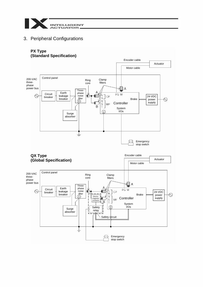
3. Peripheral Configurations
PX Type (Standard Specification)
QX Type (Global Specification)
200-VAC three-phase power bus
Control panel
Circuit breaker
Earth leakage breaker
Surge absorber
Three-phase noise filter
Ring core
Clamp filters
Encoder cable
Motor cableActuator
Controller System
I/Os
Brake24-VDC power supply
Emergency stop switch
Encoder cable
Motor cable Actuator
Electro- magnetic contactor
Safety relay
Safety circuit
200-VAC three-phase power bus
Control panel
Circuit breaker
Earth leakage breaker
Surge absorber
Three-phase noise filter
Ring core
Clamp filters
Controller System
I/Os
Brake24-VDC power supply
Emergency stop switch
(1) Environment
Use your X-SEL-PX/QX controller in an environment conforming to pollution degree 2 or 1 as specified in IEC 60664-1. Example) Install the controller in a control panel having a structure resistant to intrusion of water, oil,
carbon, dust, etc. (IP54). (2) Power Source
(A) Use the controller in an environment conforming to overvoltage category II as specified in IEC 60664-1. To meet this requirement, be sure to install a circuit breaker between the distribution board and the X-SEL controller.
(B) If the I/O power or electromagnetic brake power is supplied externally, use a 24-VDC power supply bearing a CE Mark.
(3) Grounding
To prevent electric shock, be sure to connect the FG terminal of the X-SEL-PX/QX controller and the protective grounding terminal (grounding plate) of the control panel.
(4) Earth Leakage Breaker
Install an earth leakage breaker (residual current device, or RCD) on the primary side of the X-SEL-PX/QX controller.
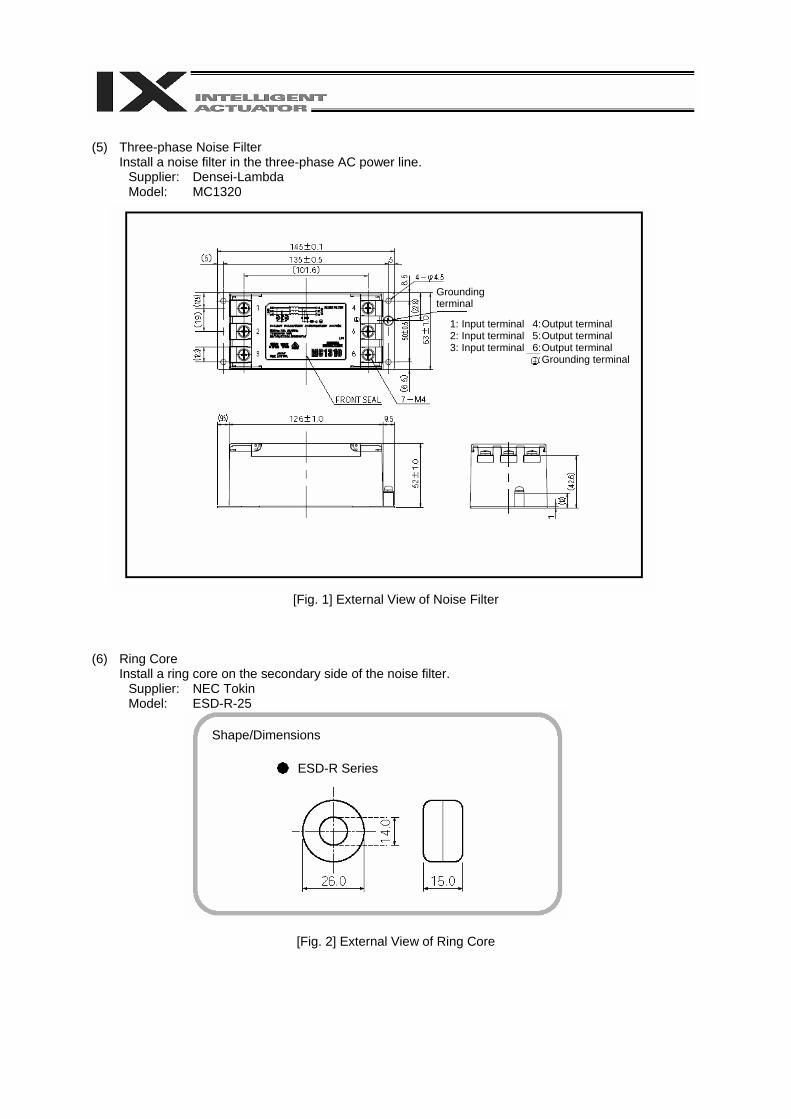
(5) Three-phase Noise Filter
Install a noise filter in the three-phase AC power line. Supplier: Densei-Lambda Model: MC1320
[Fig. 1] External View of Noise Filter (6) Ring Core
Install a ring core on the secondary side of the noise filter. Supplier: NEC Tokin Model: ESD-R-25
[Fig. 2] External View of Ring Core
Grounding terminal
1: Input terminal 4: Output terminal 2: Input terminal 5: Output terminal 3: Input terminal 6: Output terminal : Grounding terminal
Shape/Dimensions
ESD-R Series
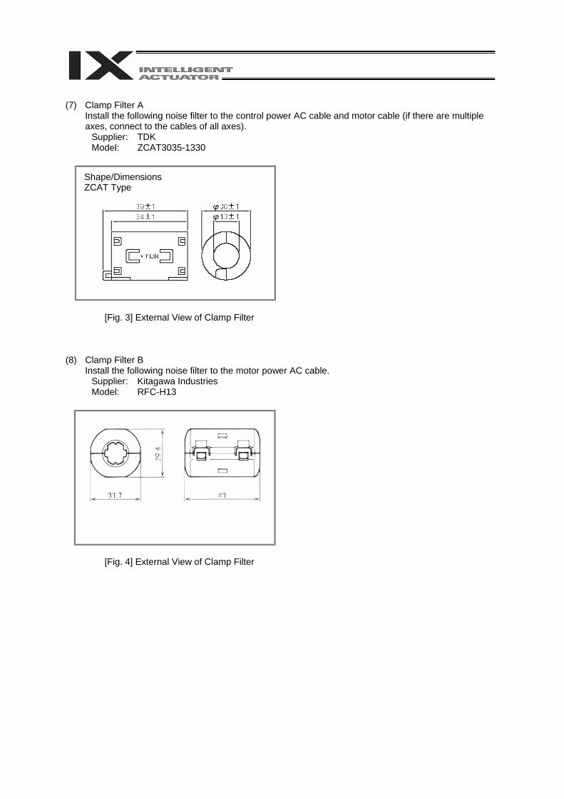
(7) Clamp Filter A
Install the following noise filter to the control power AC cable and motor cable (if there are multiple axes, connect to the cables of all axes).
Supplier: TDK Model: ZCAT3035-1330
[Fig. 3] External View of Clamp Filter (8) Clamp Filter B
Install the following noise filter to the motor power AC cable. Supplier: Kitagawa Industries Model: RFC-H13
[Fig. 4] External View of Clamp Filter
Shape/Dimensions ZCAT Type
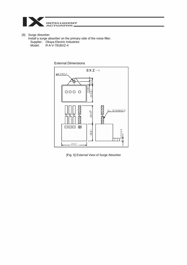
(9) Surge Absorber
Install a surge absorber on the primary side of the noise filter. Supplier: Okaya Electric Industries Model: R A V-781BXZ-4
External Dimensions
[Fig. 5] External View of Surge Absorber
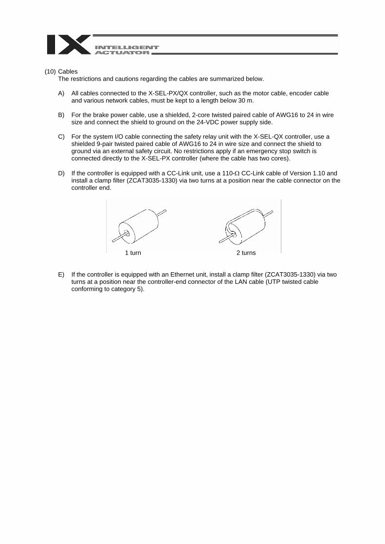
(10) Cables
The restrictions and cautions regarding the cables are summarized below.
A) All cables connected to the X-SEL-PX/QX controller, such as the motor cable, encoder cable and various network cables, must be kept to a length below 30 m.
B) For the brake power cable, use a shielded, 2-core twisted paired cable of AWG16 to 24 in wire
size and connect the shield to ground on the 24-VDC power supply side. C) For the system I/O cable connecting the safety relay unit with the X-SEL-QX controller, use a
shielded 9-pair twisted paired cable of AWG16 to 24 in wire size and connect the shield to ground via an external safety circuit. No restrictions apply if an emergency stop switch is connected directly to the X-SEL-PX controller (where the cable has two cores).
D) If the controller is equipped with a CC-Link unit, use a 110-Ω CC-Link cable of Version 1.10 and
install a clamp filter (ZCAT3035-1330) via two turns at a position near the cable connector on the controller end.
1 turn 2 turns
E) If the controller is equipped with an Ethernet unit, install a clamp filter (ZCAT3035-1330) via two turns at a position near the controller-end connector of the LAN cable (UTP twisted cable conforming to category 5).
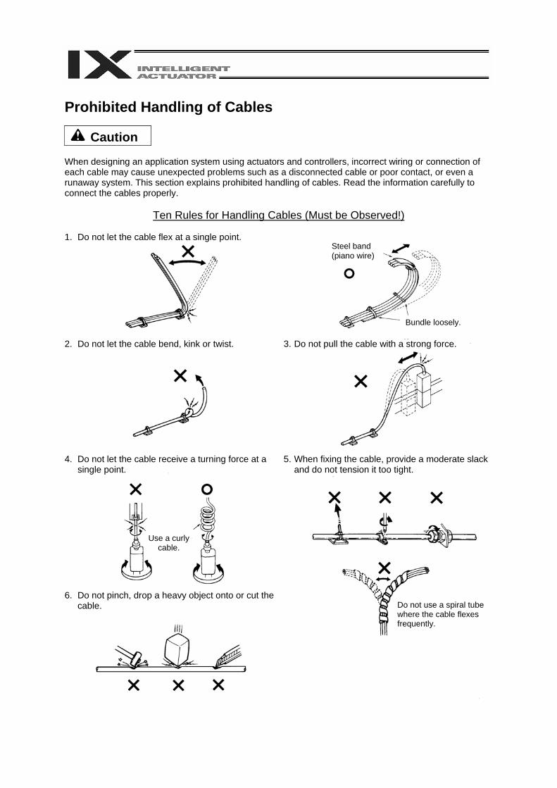
Prohibited Handling of Cables
Caution When designing an application system using actuators and controllers, incorrect wiring or connection of each cable may cause unexpected problems such as a disconnected cable or poor contact, or even a runaway system. This section explains prohibited handling of cables. Read the information carefully to connect the cables properly.
Ten Rules for Handling Cables (Must be Observed!) 1. Do not let the cable flex at a single point.
2. Do not let the cable bend, kink or twist.
3. Do not pull the cable with a strong force.
4. Do not let the cable receive a turning force at a single point.
6. Do not pinch, drop a heavy object onto or cut the
cable.
5. When fixing the cable, provide a moderate slack and do not tension it too tight.
Steel band (piano wire)
Bundle loosely.
Use a curly cable.
Do not use a spiral tube where the cable flexes frequently.
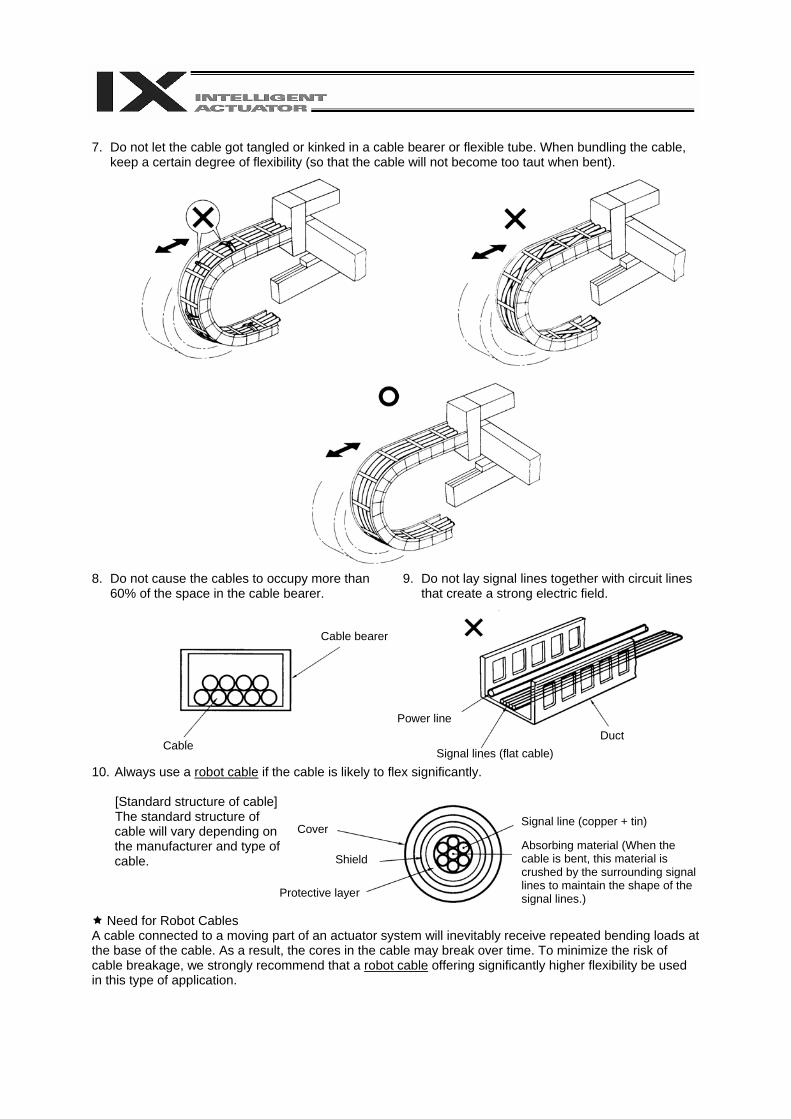
7. Do not let the cable got tangled or kinked in a cable bearer or flexible tube. When bundling the cable,
keep a certain degree of flexibility (so that the cable will not become too taut when bent). 8. Do not cause the cables to occupy more than
60% of the space in the cable bearer.
9. Do not lay signal lines together with circuit lines that create a strong electric field.
10. Always use a robot cable if the cable is likely to flex significantly.
[Standard structure of cable] The standard structure of cable will vary depending on the manufacturer and type of cable.
Need for Robot Cables A cable connected to a moving part of an actuator system will inevitably receive repeated bending loads at the base of the cable. As a result, the cores in the cable may break over time. To minimize the risk of cable breakage, we strongly recommend that a robot cable offering significantly higher flexibility be used in this type of application.
Cable
Cable bearer
Power line
Signal lines (flat cable)Duct
Absorbing material (When the cable is bent, this material is crushed by the surrounding signal lines to maintain the shape of the signal lines.)
Cover
Shield
Protective layer
Signal line (copper + tin)

Before Use
Caution
Caution 1. Be sure to read this operation manual to ensure the proper use of this product. 2. Unauthorized use or reproduction of a part or all of this operation manual is prohibited. 3. Always handle or operate the product in manners specified in this operation manual, by assuming that
whatever is not specified herein is not feasible. The warranty does not cover any defect arising from a handling or operation not specified in this operation manual.
4. The information contained in this operation manual is subject to change without notice for the purpose of modification and improvement. * If you have purchased PC software:
Always back up the parameters after installing the product or changing the parameter settings. 5. The specifications in this manual may not apply to a custom product.
Caution
Action to Be Taken in Case of Emergency
If this product is found to be in a dangerous condition, immediately turn off all power switches of the main unit and connected equipment or immediately disconnect all power cables from the outlets. (“Dangerous condition” refers to a situation where the product is generating abnormal heat or smoke or has ignited and a fire or danger to human health is anticipated.)
Table of Contents
Table of Contents
Introduction...................................................................................................................... 1
Part 1 Installation........................................................................................................... 3
Chapter 1 Safety Precautions............................................................................................................... 3
Chapter 2 Warranty Period and Scope of Warranty ............................................................................. 4 1. Warranty Period........................................................................................................................... 4 2. Scope of Warranty ....................................................................................................................... 4 3. Scope of Service ......................................................................................................................... 4
Chapter 3 Installation Environment and Selection of Auxiliary Power Devices.................................... 5 1. Installation Environment .............................................................................................................. 5 2. Heat Radiation and Installation.................................................................................................... 6 3. Selection of Auxiliary Power Devices .......................................................................................... 7 4. Noise Control Measures and Grounding ....................................................................................11
Chapter 4 Name and Function of Each Part....................................................................................... 14 1. Front View of Controller............................................................................................................. 14 2. Explanation of Codes Displayed on the Panel Window ............................................................ 28
2.1 Application....................................................................................................................... 28 2.2 Core................................................................................................................................. 29 2.3 Current Monitor and Variable Monitor ............................................................................. 30
Chapter 5 Specifications..................................................................................................................... 32 1. Controller Specifications ............................................................................................................ 32 2. External I/O Specifications......................................................................................................... 36
2.1. NPN Specification............................................................................................................ 36 2.2. PNP Specification............................................................................................................ 38
3. Power Source Capacity and Heat Output ................................................................................. 40 4. External Dimensions.................................................................................................................. 45
Chapter 6 Safety Circuit...................................................................................................................... 54 1. Items to Notes ........................................................................................................................... 54 2. Safety Circuit for P Type (Standard Specification) Controller .................................................... 55 3. Safety Circuit for Q Type (Global Specification) Controller ....................................................... 57
Chapter 7 System Setup..................................................................................................................... 62 1. Connection Method of Controller and Actuator ......................................................................... 62 2. I/O Connection Diagram............................................................................................................ 66
Table of Contents
Chapter 8 How to Perform An Absolute Encoder Reset of A Direct Movement Axis (Absolute Specification) ..................................................................................................... 69
1. Preparation ................................................................................................................................ 69 2. Procedure .................................................................................................................................. 69
Chapter 9 Maintenance ...................................................................................................................... 75 1. Inspection points........................................................................................................................ 75 2. Spare consumable parts............................................................................................................ 75 3. Replacement Procedure for System Memory Backup Battery.................................................. 76 4. Replacement Procedure for Absolute-Encoder Backup Battery for Linear Movement Axis ..... 79
Part 2 Operation .......................................................................................................... 82
Chapter 1 Operation ........................................................................................................................... 82 1. Starting a Program by Auto Start via Parameter Setting ........................................................... 83 2. Starting via External Signal Selection........................................................................................ 84 3. Drive Source Recovery Request and Operation Pause Reset Request ................................... 86
Part 3 Controller Data Structure .................................................................................. 87
Chapter 1 How to Save Data .............................................................................................................. 88 1. Factory Settings: When the System Memory Backup Battery is Used ..................................... 88 2. When the System Memory Backup Battery is Not Used........................................................... 89 3. Points to Note ............................................................................................................................ 90
Chapter 2 X-SEL Language Data ....................................................................................................... 91 1. Values and Symbols Used in SEL Language............................................................................ 91
1.1 List of Values and Symbols Used.................................................................................... 91 1.2 I/O Ports .......................................................................................................................... 92 1.3 Virtual I/O Ports ............................................................................................................... 93 1.4 Flags................................................................................................................................ 95 1.5 Variables.......................................................................................................................... 96 1.6 Tags................................................................................................................................. 99 1.7 Subroutines ................................................................................................................... 100 1.8 Symbols......................................................................................................................... 101 1.9 Character String Literals................................................................................................ 101 1.10 Axis Specification .......................................................................................................... 102
2. Position Part ............................................................................................................................ 104 3. Command Part ........................................................................................................................ 105
3.1 SEL language Structure ................................................................................................ 105 3.2 Extension Condition ...................................................................................................... 106
Table of Contents
Part 4 Commands ..................................................................................................... 107
Chapter 1 List of SEL Language Command Codes ......................................................................... 107
Chapter 2 Explanation of Commands................................................................................................118 1. Commands ...............................................................................................................................118
1.1 Variable Assignment.......................................................................................................118 1.2 Arithmetic Operation...................................................................................................... 120 1.3 Function Operation........................................................................................................ 123 1.4 Logical Operation .......................................................................................................... 128 1.5 Comparison Operation .................................................................................................. 131 1.6 Timer ............................................................................................................................. 132 1.7 I/O, Flag Operation........................................................................................................ 135 1.8 Program Control ............................................................................................................ 146 1.9 Task Management ......................................................................................................... 149 1.10 Position Operation......................................................................................................... 154 1.11 Actuator Control Declaration ......................................................................................... 169 1.12 Actuator Control Command........................................................................................... 204 1.13 Structural IF ................................................................................................................... 236 1.14 Structural DO................................................................................................................. 239 1.15 Multi-Branching ............................................................................................................. 241 1.16 System Information Acquisition ..................................................................................... 245 1.17 Zone .............................................................................................................................. 249 1.18 Communication ............................................................................................................. 253 1.19 String Operation ............................................................................................................ 258 1.20 Palletizing-Related ........................................................................................................ 267 1.21 Palletizing Calculation Command ................................................................................. 282 1.22 Palletizing Movement Command .................................................................................. 285 1.23 Building of Pseudo-Ladder Task ................................................................................... 291
Chapter 3 Key Characteristics of Horizontal Articulated Robot Operation ....................................... 293 1. CP Operation and PTP Operation ........................................................................................... 293 2. Arm System ............................................................................................................................. 296 3. SCARA Coordinate System..................................................................................................... 304 4. Simple Interference Check Zone (Dedicated SCARA Function) ............................................. 314 5. Soft Limits of SCARA Axes...................................................................................................... 317
Chapter 4 Key Characteristics of Actuator Control Commands and Points to Note......................... 321 1. Continuous Movement Commands
[PATH, PSPL, CIR2, ARC2, CIRS, ARCS, ARCD, ARCC, CIR, ARC] .................................... 321 2. PATH/PSPL Commands .......................................................................................................... 323 3. CIR/ARC Commands .............................................................................................................. 323 4. CIR2/ARC2/ARCD/ARCC Commands.................................................................................... 323
Table of Contents
Chapter 5 Palletizing Function.......................................................................................................... 324 1. How to Use .............................................................................................................................. 324 2. Palletizing Setting .................................................................................................................... 324 3. Palletizing Calculation ............................................................................................................. 330 4. Palletizing Movement .............................................................................................................. 331 5. Program Examples .................................................................................................................. 333
Chapter 6 Pseudo-Ladder Task ........................................................................................................ 337 1. Basic Frame............................................................................................................................. 337 2. Ladder Statement Field ........................................................................................................... 338 3. Points to Note .......................................................................................................................... 338 4. Program Example.................................................................................................................... 339
Chapter 7 Multi-Tasking .................................................................................................................... 340 1. Difference from a Sequencer................................................................................................... 340 2. Release of Emergency Stop.................................................................................................... 341 3. Program Switching .................................................................................................................. 342
* Appendix ................................................................................................................... 343 List of Additional Linear Movement Axis Specifications........................................................... 343 Battery Backup Function ......................................................................................................... 346
1. System-Memory Backup Battery ................................................................................ 346 2. Absolute-Encoder Backup Battery.............................................................................. 348
Expansion Board (Optional) .................................................................................................... 350 Number of Regenerative Units to Be Connected .................................................................... 351 List of Parameters ................................................................................................................... 352
1. I/O Parameters ........................................................................................................... 353 2. Parameters Common to All Axes................................................................................ 366 3. Axis-Specific Parameters............................................................................................ 373 4. Driver Card Parameters.............................................................................................. 383 5. Encoder Parameters................................................................................................... 386 6. I/O Device Parameters ............................................................................................... 387 7. Other Parameters ....................................................................................................... 388 8. Manual Operation Types............................................................................................. 393 9. Use Examples of Key Parameters.............................................................................. 394

Table of Contents
Combination Table of X-SEL PX/QX Axis 5/6 Linear/Rotary Control Parameter ............................ 400 Error Level Control .......................................................................................................................... 401 Error List .......................................................................................................................................... 403 Troubleshooting of X-SEL Controller............................................................................................... 446 Trouble Report Sheet ...................................................................................................................... 449
1
Introduction
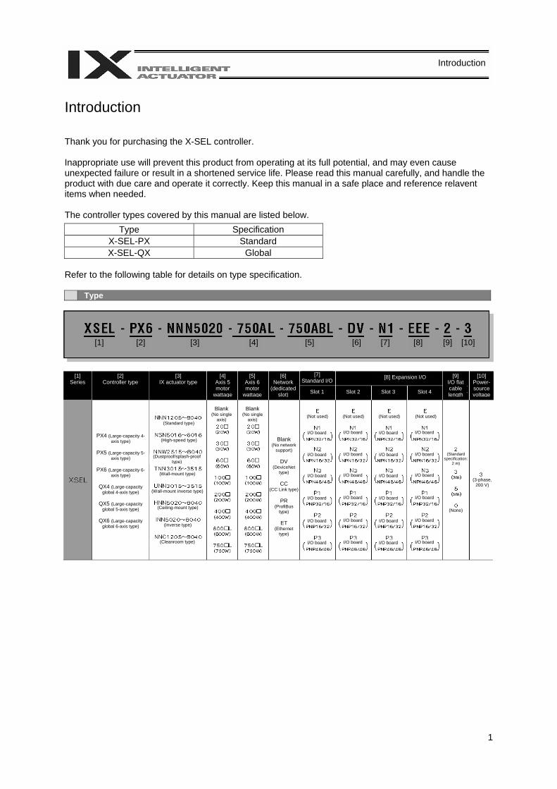
Introduction Thank you for purchasing the X-SEL controller. Inappropriate use will prevent this product from operating at its full potential, and may even cause unexpected failure or result in a shortened service life. Please read this manual carefully, and handle the product with due care and operate it correctly. Keep this manual in a safe place and reference relavent items when needed. The controller types covered by this manual are listed below.
Type Specification X-SEL-PX Standard X-SEL-QX Global
Refer to the following table for details on type specification. Type
[1] Series
[2] Controller type
[3] IX actuator type
[4] Axis 5 motor
wattage
[5] Axis 6 motor
wattage
[6] Network
(dedicated slot)
[7] Standard I/O
Slot 1 Slot 2 Slot 3 Slot 4
[8] Expansion I/O [9] I/O flat cable length
[10] Power-source voltage
PX4 (Large-capacity 4-axis type)
PX5 (Large-capacity 5-axis type)
PX6 (Large-capacity 6-axis type)
QX4 (Large-capacity global 4-axis type)
QX5 (Large-capacity global 5-axis type)
QX6 (Large-capacity global 6-axis type)
(Standard type)
(High-speed type)
(Dustproof/splash-proof type)
(Wall-mount type)
(Wall-mount inverse type)
(Ceiling-mount type)
(Inverse type)
(Cleanroom type)
Blank (No single
axis)
Blank (No single
axis)
Blank (No network
support)
DV (DeviceNet
type)
CC (CC Link type)
PR (ProfiBus
type)
ET (Ethernet
type)
(Not used) (Not used) (Not used) (Not used)
I/O board
I/O board
I/O board
I/O board
I/O board
I/O board
I/O board
I/O board
I/O board
I/O board
I/O board
I/O board
I/O board
I/O board
I/O board
I/O board
I/O board
I/O board
I/O board
I/O board
I/O board
I/O board
I/O board
I/O board
(Standard specification:
2 m)
(3-phase, 200 V)
[1] [2] [3] [4] [5] [6] [7] [8] [9] [10]
(None)

2
Introduction
The controller receives power in order to drive the actuator motor(s) (three phase, 200 to 220 V) and to operate the controller itself (single phase, 200 to 220 V). The actuator motor drive power supply is controlled independently of the control power supply, and the internal operations of the controller are different depending on whether it is of the global specification or standard specification. With the standard controller, the main CPU in the system performs all self-diagnosis checks and supplies power to the drive part only when the system can operate properly. With the global controller, the user must provide a separate circuit that cuts off the three phase 200 VAC motor power supplied to the controller. If this drive power cutoff circuit is not provided, safe operation of the controller cannot be guaranteed.
With the global controller, always configure a safety circuit (drive-source cutoff circuit). • Turn on the controller power before or simultaneously with the motor power. • Turn off the controller power after or simultaneously with the motor power. • Before performing a check or inserting/removing a connector, turn off the power and wait for at least 10
minutes. Even after the power is turned off, the internal circuits will continue to carry high voltages for a short period.
• IAI recommends that our actuators be used at a duty of 50% or less as a guideline in view of the relationship of service life and accuracy:
Duty (%) = Inactivity time Motion
Time onDecelerati / onAccelerati+
X 100
• After turning off the control power, be sure to wait for at least 5 seconds before turning it back on. Any shorter interval may generate “E88: Power system error (Other).”
• Do not insert or remove connectors while the controller power is on. Doing so may cause a malfunction.
• Follow the steps below to initialize the absolute data backup battery circuit and thereby prevent early consumption of the battery:
[1] Set the absolute data backup battery enable/disable switch to the bottom position. (The controller is shipped with this switch set to the bottom position.)
[2] Connect the encoder cable. [3] Turn on the power. [4] Set the absolute data backup battery enable/disable switch to the
top (ENB) position. If the encoder cable of a linear movement axis was removed to relocate the actuator, etc., you must always perform the above steps. Read the operation manual for each actuator. If you have purchased our optional PC software and/or teaching pendant, read the respective operation manuals, as well. * Utmost effort has been made to ensure that the information contained in this manual is true and
correct. However, should you find any error or if you have any comment regarding the content, please contact IAI.

3
Part 1 Installation
Part 1 Installation
Caution Chapter 1 Safety Precautions The X-SEL PX/QX Controller can support a combination of a SCARA robot and linear movement axes to perform integrated control of all axes including peripheral equipment. In other words, the controller has the ability to control systems of all sizes ranging from a small system to a large factory automation system. In general, however, the occurrence rate of accidents due to incorrect operation or carelessness will rise as the system becomes larger and more complex. Please give due consideration to safety measures. This system product was developed as a drive unit for an automated machine, and as such the maximum torque and speed are limited to levels acceptable for an automatically driven machine. However, strict observance of the following items is required to prevent accidents. Also read the appendix entitled, “Safety Rules and Others.” 1. Do not handle this product in a manner not specified in this manual. If you have any question regarding
the content of this manual, please contact IAI. 2. Always use the specified, genuine IAI cables for wiring between the controller and the actuator. 3. Do not enter the operation area of the machine while the machine is operating or ready to operate (the
controller power is on). If the machine is used in a place accessible to other people, provide an appropriate safety measure such as enclosing the machine with a cage.
4. When assembling/adjusting or maintaining/inspecting the machine, always turn off the controller power
at the source beforehand. The operator should display in a conspicuous place a sign saying that operation is in progress and that the power should not be turned on. The operator should keep the entire power cable beside him or her to prevent another person from inadvertently plugging in the cable.
5. When two or more operators are to work together, they should communicate to ensure safety of all
personnel during the work. In particular, a person turning on/off the power or moving an axis—either via a motor or manually—must always say what he or she is going to do and confirm the responses from the others first before actually performing the operation.
4
Part 1 Installation
Chapter 2 Warranty Period and Scope of Warranty The X-SEL Controller you have purchased passed our strict outgoing inspection. This unit is covered by the following warranty: 1. Warranty Period The warranty period shall be either of the following periods, whichever ends first:
• 18 months after shipment from our factory • 12 months after delivery to a specified location 2. Scope of Warranty Should the product fail during the above period under a proper use condition due to a fault on the part of the manufacturer, IAI will repair the defect free of charge. However, the following cases are excluded from the scope of warranty: • Discoloration of paint or other normal aging • Wear of consumable parts due to use • Subjective imperfection, such as noise not affecting mechanical function • Defect caused by inappropriate handling or use by the user • Defect caused by inappropriate or erroneous maintenance/inspection • Defect caused by use of a part other than IAI’s genuine part • Defect caused by unauthorized modification, etc., not approved by IAI or its agent • Defect due to an act of God, accident, fire, etc. The warranty covers only the product as it is delivered. IAI shall not be liable for any loss arising in connection with the delivered product. The user must bring the defective product to our factory to receive a warranty repair. 3. Scope of Service The price of the delivered product does not include costs incurred in association with program generation, dispatch of technician, etc. Therefore, a separate fee will be chargeable in the following cases even during the warranty period: • Guidance on installation/adjustment and witnessing of test operation • Maintenance/inspection • Technical guidance and training on operation, wiring method, etc. • Technical guidance and training regarding programs, such as program generation • Other services and operations where IAI finds a need to charge a separate fee
5
Part 1 Installation
Chapter 3 Installation Environment and Selection of Auxiliary Power
Devices 1. Installation Environment (1) When installing and wiring the controller, do not block the ventilation holes provided for cooling
(insufficient ventilation will not only prevent the product from functioning fully, but it may also result in damage).
(2) Prevent foreign matter from entering the controller through the ventilation holes. Since the controller is not designed as dustproof or waterproof, avoid using it in a dusty place or a place subject to water mist, oil, or cutting fluid.
(3) Do not expose the controller to direct sunlight or radiant heat from a high heat source. (4) Use the controller in a non-condensing environment free from corrosive or inflammable gases. (5) Use the controller in an environment where it will not receive external vibration or impact. (6) Prevent electrical noise from entering the controller or its cables. Environmental Condition of Controller
Item Specification and description Operating Temperature Range 0 ~ 40°C
Operating Humidity Range 10% ~ 95% (non-condensing; conforming to JIS C3502 RH-2) Storage Temperature Range -25°C ~ 70°C (excluding the battery) Maximum Operating Altitude 2000 m
Protection Class IP20
Vibration 10 ≤ f < 57: 0.035 mm (continuous), 0.075 mm (intermittent) 57 ≤ f ≤ 150: 4.9 m/s2 (continuous), 9.8 m/s2 (intermittent) X, Y and Z directions
Impact 147 mm/s2, 11 ms, half-sine pulse, 3 times each in X, Y and Z directions
Electrical Specifications of Controller
Item Specification Power-source Voltage Three-phase, 200 ~ 230 VAC ± 10%
Power-source Frequency 50/60 Hz ± 5% (conforming to JIS C3502 RH-2) Momentary Power Failure
Resistance 0.5 cycle (phase independent)
Electric Shock Protection Class I: Basic insulation, grounding by ground terminal
Overvoltage Class Class II: Withstand voltage of 2500 V at voltage inputs below 300 VAC (rated input)
Pollution Degree Pollution degree 2
Rush Current
120 A max. for motor power, 50 A max. for control power (at 40°C, 200-VAC input) The level of rush current will vary depending on the power-source environment. The above values are provided for reference purpose only.
Leak current 3.5 mA max. (controller only without any axes connected)
6
Part 1 Installation
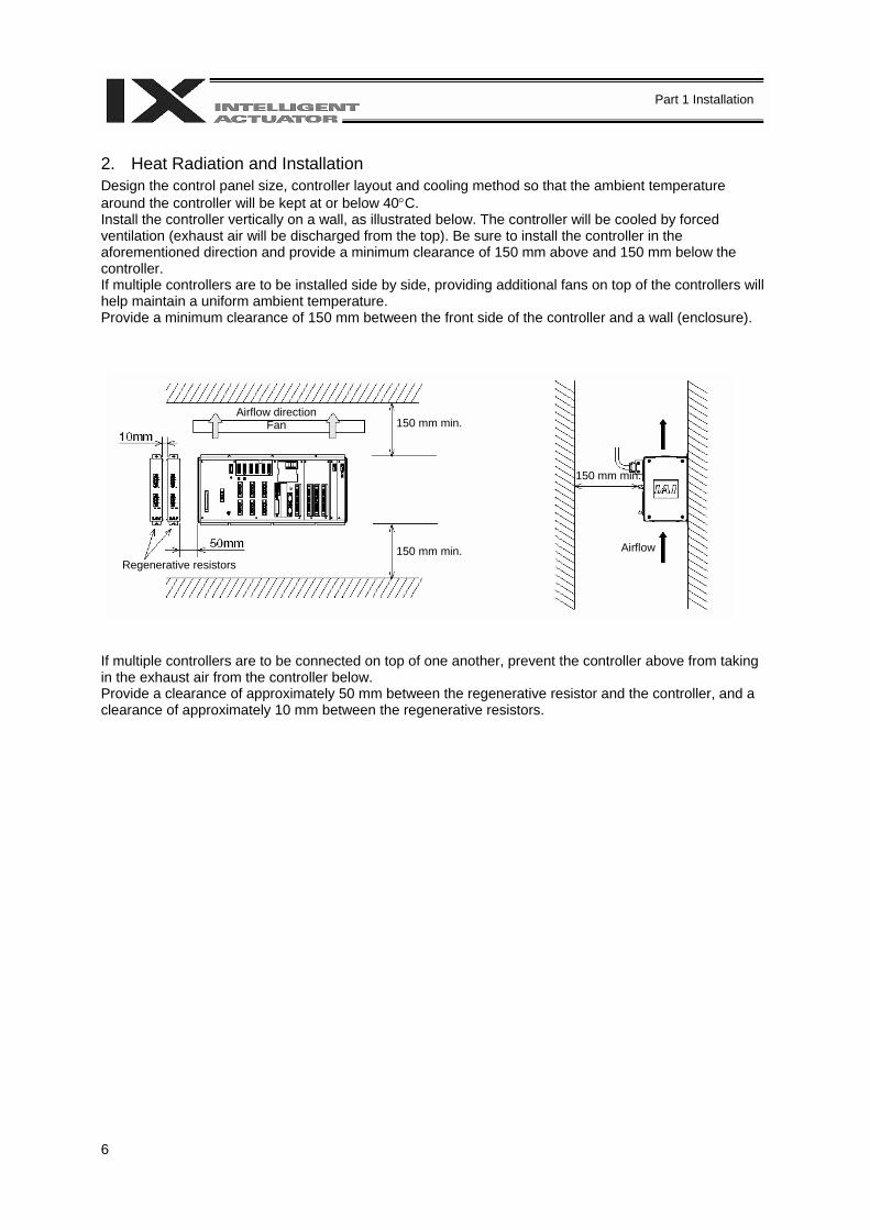
2. Heat Radiation and Installation Design the control panel size, controller layout and cooling method so that the ambient temperature around the controller will be kept at or below 40°C. Install the controller vertically on a wall, as illustrated below. The controller will be cooled by forced ventilation (exhaust air will be discharged from the top). Be sure to install the controller in the aforementioned direction and provide a minimum clearance of 150 mm above and 150 mm below the controller. If multiple controllers are to be installed side by side, providing additional fans on top of the controllers will help maintain a uniform ambient temperature. Provide a minimum clearance of 150 mm between the front side of the controller and a wall (enclosure). If multiple controllers are to be connected on top of one another, prevent the controller above from taking in the exhaust air from the controller below. Provide a clearance of approximately 50 mm between the regenerative resistor and the controller, and a clearance of approximately 10 mm between the regenerative resistors.
Airflow direction Fan
Airflow
150 mm min.
150 mm min.
150 mm min.
Regenerative resistors
7
Part 1 Installation
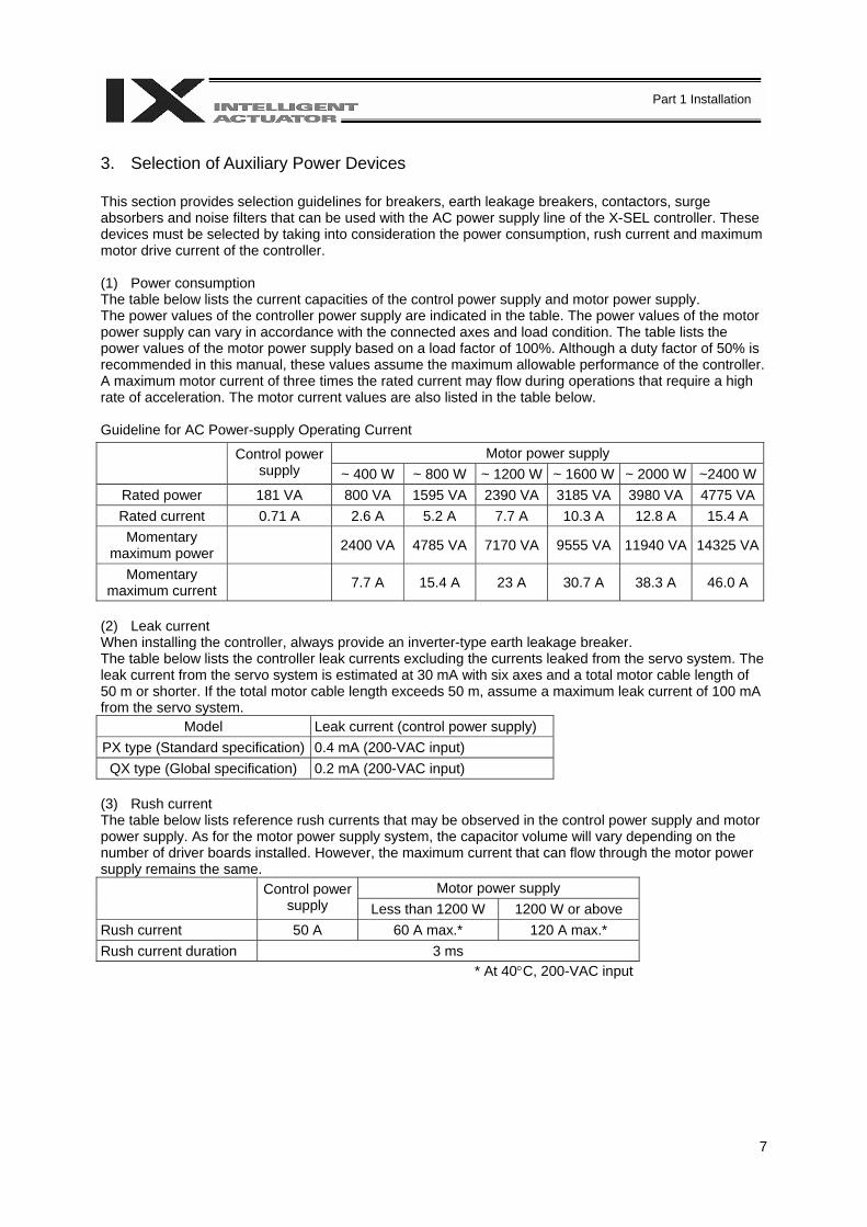
3. Selection of Auxiliary Power Devices This section provides selection guidelines for breakers, earth leakage breakers, contactors, surge absorbers and noise filters that can be used with the AC power supply line of the X-SEL controller. These devices must be selected by taking into consideration the power consumption, rush current and maximum motor drive current of the controller. (1) Power consumption The table below lists the current capacities of the control power supply and motor power supply. The power values of the controller power supply are indicated in the table. The power values of the motor power supply can vary in accordance with the connected axes and load condition. The table lists the power values of the motor power supply based on a load factor of 100%. Although a duty factor of 50% is recommended in this manual, these values assume the maximum allowable performance of the controller. A maximum motor current of three times the rated current may flow during operations that require a high rate of acceleration. The motor current values are also listed in the table below. Guideline for AC Power-supply Operating Current
Motor power supply Control power supply ~ 400 W ~ 800 W ~ 1200 W ~ 1600 W ~ 2000 W ~2400 W
Rated power 181 VA 800 VA 1595 VA 2390 VA 3185 VA 3980 VA 4775 VA Rated current 0.71 A 2.6 A 5.2 A 7.7 A 10.3 A 12.8 A 15.4 A Momentary
maximum power 2400 VA 4785 VA 7170 VA 9555 VA 11940 VA 14325 VA
Momentary maximum current 7.7 A 15.4 A 23 A 30.7 A 38.3 A 46.0 A
(2) Leak current When installing the controller, always provide an inverter-type earth leakage breaker. The table below lists the controller leak currents excluding the currents leaked from the servo system. The leak current from the servo system is estimated at 30 mA with six axes and a total motor cable length of 50 m or shorter. If the total motor cable length exceeds 50 m, assume a maximum leak current of 100 mA from the servo system.
Model Leak current (control power supply) PX type (Standard specification) 0.4 mA (200-VAC input) QX type (Global specification) 0.2 mA (200-VAC input)
(3) Rush current The table below lists reference rush currents that may be observed in the control power supply and motor power supply. As for the motor power supply system, the capacitor volume will vary depending on the number of driver boards installed. However, the maximum current that can flow through the motor power supply remains the same.
Motor power supply Control power supply Less than 1200 W 1200 W or above
Rush current 50 A 60 A max.* 120 A max.* Rush current duration 3 ms
* At 40°C, 200-VAC input

8
Part 1 Installation
(4) Auxiliary power devices [1] Breaker or electromagnetic contactor
Install a circuit breaker or earth leakage breaker in the AC power supply line (primary side) of the controller in order to prevent damage due to power switching and short circuit. One circuit breaker or earth leakage breaker can be used to protect both the motor power supply and control power supply. If your controller is of the global specification, an electromagnetic contactor must be installed in front of the motor power input port on the controller so that the motor drive source can be cut off. Select a product that meets your requirement. Refer to Chapter 6, “Safety Circuit,” for the configuration of the safety circuit.
[2] Noise filter, ferrite core and clamp filters
The global specification doesn’t have a noise filter in the motor power supply. If your controller is of the global specification, be sure to install noise filters and ring cores for the motor drive power supply external to the controller. The standard controller should also have filters and ferrite cores installed in the power circuit to prevent noise from reaching sensitive external equipment. With both the global specification and standard specification, use the same noise filters and ring cores to protect the motor power supply and control power supply.
Install clamp filters to ensure compliance with the EC Directives or for other reasons, if necessary. • Clamp filter A
Install this clamp filter on the control power cable and motor cable (if there are multiple axes, connect to the cables of all axes).
• Clamp filter B Install this clamp filter to the motor power cable.
Caution: Be sure to use the following noise filter, ring core and clamp filters to ensure compliance with the EC Directives (IAI uses the following filters in the evaluation certification tests under the EMC Directives).
Recommended Noise Filter, Ring Core and Clamp Filters
Supplier Model Noise filter Densei-Lambda MC1320 Ferrite Core NEC Tokin ESD-R-25 Clamp filter A TDK ZCAT3035-1330 Clamp filter B Kitagawa Industries RFC-H13

9
Part 1 Installation
[3] Surge absorber
With both the global specification and standard specification, the motor drive part of the X-SEL controller does not have a built-in surge absorber to protect the equipment against surges that may be generated due to lightning, etc. Therefore, a surge absorber must be installed externally to the controller if you want to increase the surge resistance of your equipment.
Caution: Be sure to use the following surge absorber to ensure compliance with the EC Directives. Recommended surge absorber: R/A/V-781BXZ-4 by Okaya Electric Industries
Peripheral configurations for the global and standard specifications are shown on the following pages.
10
Part 1 Installation
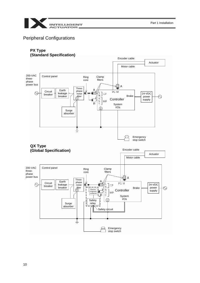
Peripheral Configurations
PX Type (Standard Specification)
QX Type (Global Specification)
200-VAC three-phase power bus
Control panel
Circuit breaker
Earth leakage breaker
Surge absorber
Three-phase noise filter
Ring core
Clamp filters
Encoder cable
Motor cableActuator
Controller System
I/Os
Brake24-VDC power supply
Emergency stop switch
Encoder cable
Motor cableActuator
Electro- magnetic contactor
Safety relay
Safety circuit
200-VAC three-phase power bus
Control panel
Circuit breaker
Earth leakage breaker
Surge absorber
Three-phase noise filter
Ring core
Clamp filters
Controller
System I/Os
Brake24-VDC power supply
Emergency stop switch
11
Part 1 Installation
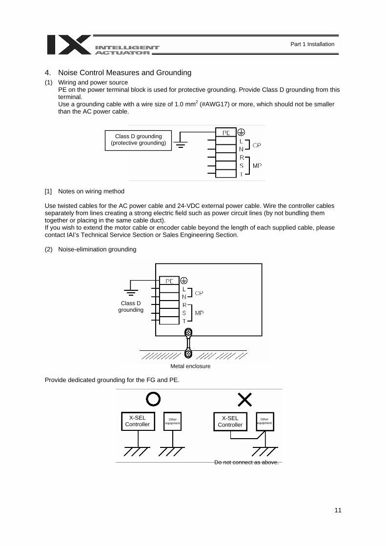
4. Noise Control Measures and Grounding (1) Wiring and power source
PE on the power terminal block is used for protective grounding. Provide Class D grounding from this terminal. Use a grounding cable with a wire size of 1.0 mm2 (#AWG17) or more, which should not be smaller than the AC power cable.
[1] Notes on wiring method Use twisted cables for the AC power cable and 24-VDC external power cable. Wire the controller cables separately from lines creating a strong electric field such as power circuit lines (by not bundling them together or placing in the same cable duct). If you wish to extend the motor cable or encoder cable beyond the length of each supplied cable, please contact IAI’s Technical Service Section or Sales Engineering Section. (2) Noise-elimination grounding Provide dedicated grounding for the FG and PE.
Class D grounding
Metal enclosure
X-SEL Controller
Other equipment
Do not connect as above.
X-SEL Controller
Other equipment
Class D grounding (protective grounding)
12
Part 1 Installation
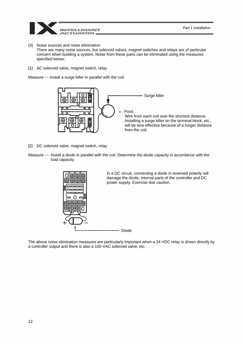
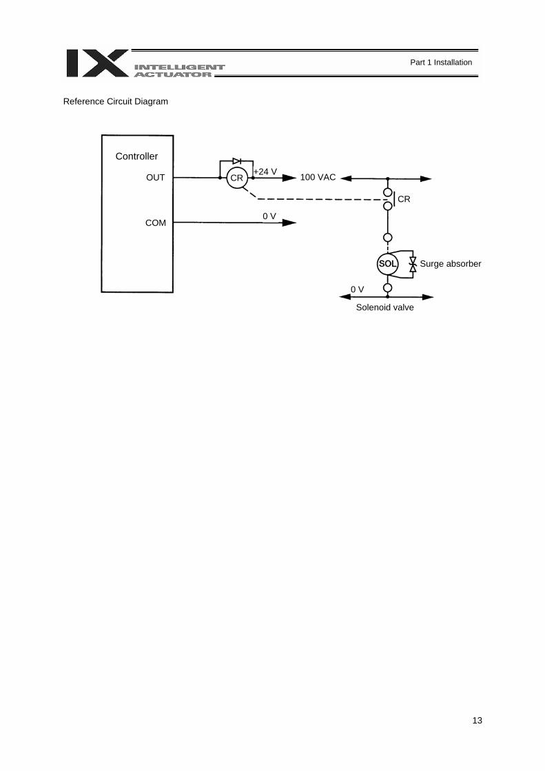
(3) Noise sources and noise elimination
There are many noise sources, but solenoid valves, magnet switches and relays are of particular concern when building a system. Noise from these parts can be eliminated using the measures specified below:
[1] AC solenoid valve, magnet switch, relay Measure --- Install a surge killer in parallel with the coil. [2] DC solenoid valve, magnet switch, relay Measure --- Install a diode in parallel with the coil. Determine the diode capacity in accordance with the
load capacity.
In a DC circuit, connecting a diode in reversed polarity will damage the diode, internal parts of the controller and DC power supply. Exercise due caution.
The above noise elimination measures are particularly important when a 24-VDC relay is driven directly by a controller output and there is also a 100-VAC solenoid valve, etc.
Surge killer
← Point Wire from each coil over the shortest distance. Installing a surge killer on the terminal block, etc., will be less effective because of a longer distance from the coil.
Diode
13
Part 1 Installation
Reference Circuit Diagram
Controller
Surge absorber
Solenoid valve
OUT
COM
CR+24 V
0 V
100 VAC
CR
0 V
14
Part 1 Installation
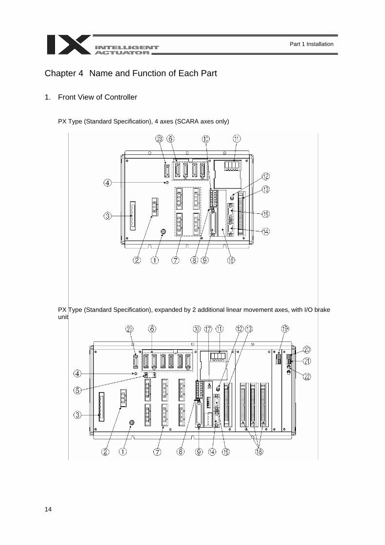
Chapter 4 Name and Function of Each Part 1. Front View of Controller
PX Type (Standard Specification), 4 axes (SCARA axes only)
PX Type (Standard Specification), expanded by 2 additional linear movement axes, with I/O brake unit
15
Part 1 Installation
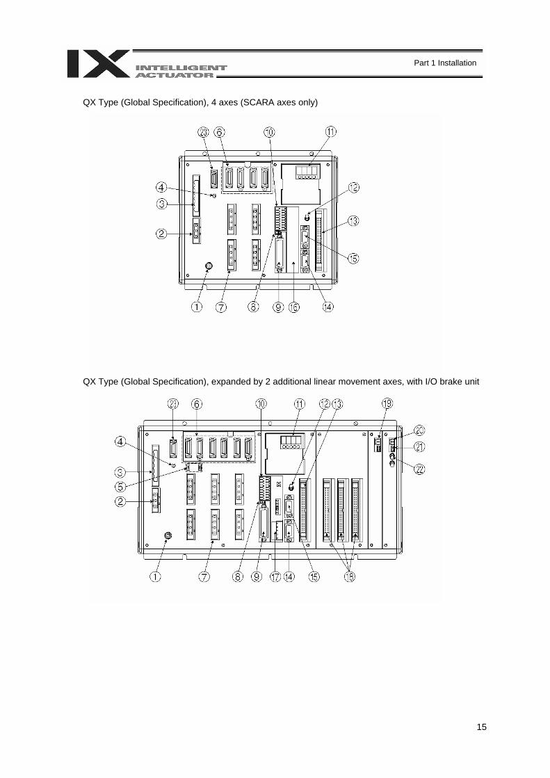
QX Type (Global Specification), 4 axes (SCARA axes only)
QX Type (Global Specification), expanded by 2 additional linear movement axes, with I/O brake unit
16
Part 1 Installation
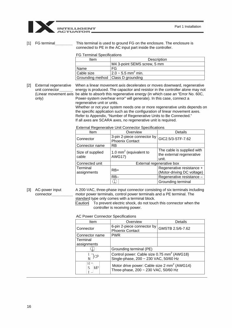
[1] FG terminal This terminal is used to ground FG on the enclosure. The enclosure is
connected to PE in the AC input part inside the controller.
FG Terminal Specifications Item Description
M4 3-point SEMS screw, 5 mm Name FG Cable size 2.0 ~ 5.5 mm2 min. Grounding method Class D grounding
[2] External regenerative unit connector (Linear movement axis only)
When a linear movement axis decelerates or moves downward, regenerative energy is produced. The capacitor and resistor in the controller alone may not be able to absorb this regenerative energy (in which case an “Error No. 60C, Power-system overhear error” will generate). In this case, connect a regenerative unit or units. Whether or not your system needs one or more regenerative units depends on the specific application such as the configuration of linear movement axes. Refer to Appendix, “Number of Regenerative Units to Be Connected.” If all axes are SCARA axes, no regenerative unit is required.
External Regenerative Unit Connector Specifications Item Overview Details
Connector 3-pin 2-piece connector by Phoenix Contact GIC2.5/3-STF-7.62
Connector name RB
Size of supplied cable
1.0 mm2 (equivalent to AWG17)
The cable is supplied with the external regenerative unit.
Connected unit External regenerative box
RB+ Regenerative resistance + (Motor-driving DC voltage)
Terminal assignments RB– Regenerative resistance – Grounding terminal
[3] AC-power input
connector A 200-VAC, three-phase input connector consisting of six terminals including motor power terminals, control power terminals and a PE terminal. The standard type only comes with a terminal block. Caution To prevent electric shock, do not touch this connector when the
controller is receiving power.
AC Power Connector Specifications Item Overview Details
Connector 6-pin 2-piece connector by Phoenix Contact GMSTB 2.5/6-7.62
Connector name PWR Terminal assignments
Grounding terminal (PE)
Control power: Cable size 0.75 mm2 (AWG18) Single-phase, 200 ~ 230 VAC, 50/60 Hz
Motor drive power: Cable size 2 mm2 (AWG14) Three-phase, 200 ~ 230 VAC, 50/60 Hz
17
Part 1 Installation
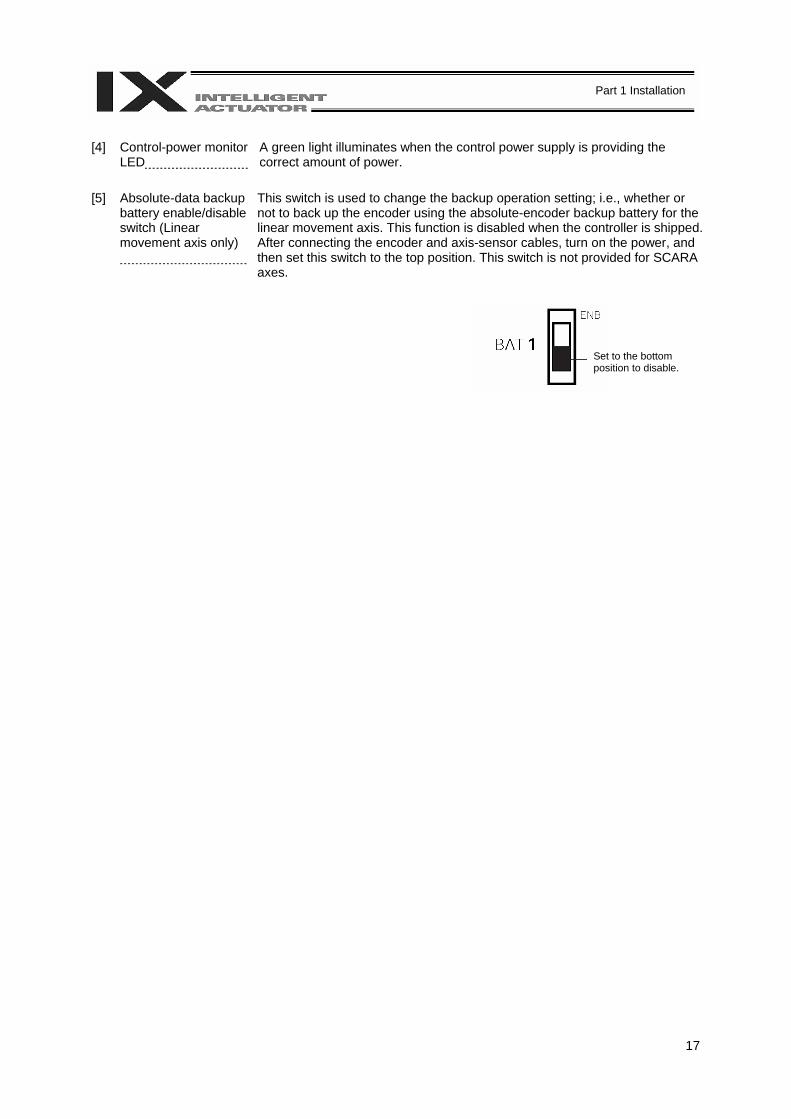
[4] Control-power monitor
LED A green light illuminates when the control power supply is providing the correct amount of power.
[5] Absolute-data backup
battery enable/disable switch (Linear movement axis only)
This switch is used to change the backup operation setting; i.e., whether or not to back up the encoder using the absolute-encoder backup battery for the linear movement axis. This function is disabled when the controller is shipped. After connecting the encoder and axis-sensor cables, turn on the power, and then set this switch to the top position. This switch is not provided for SCARA axes.
Set to the bottom position to disable.
18
Part 1 Installation
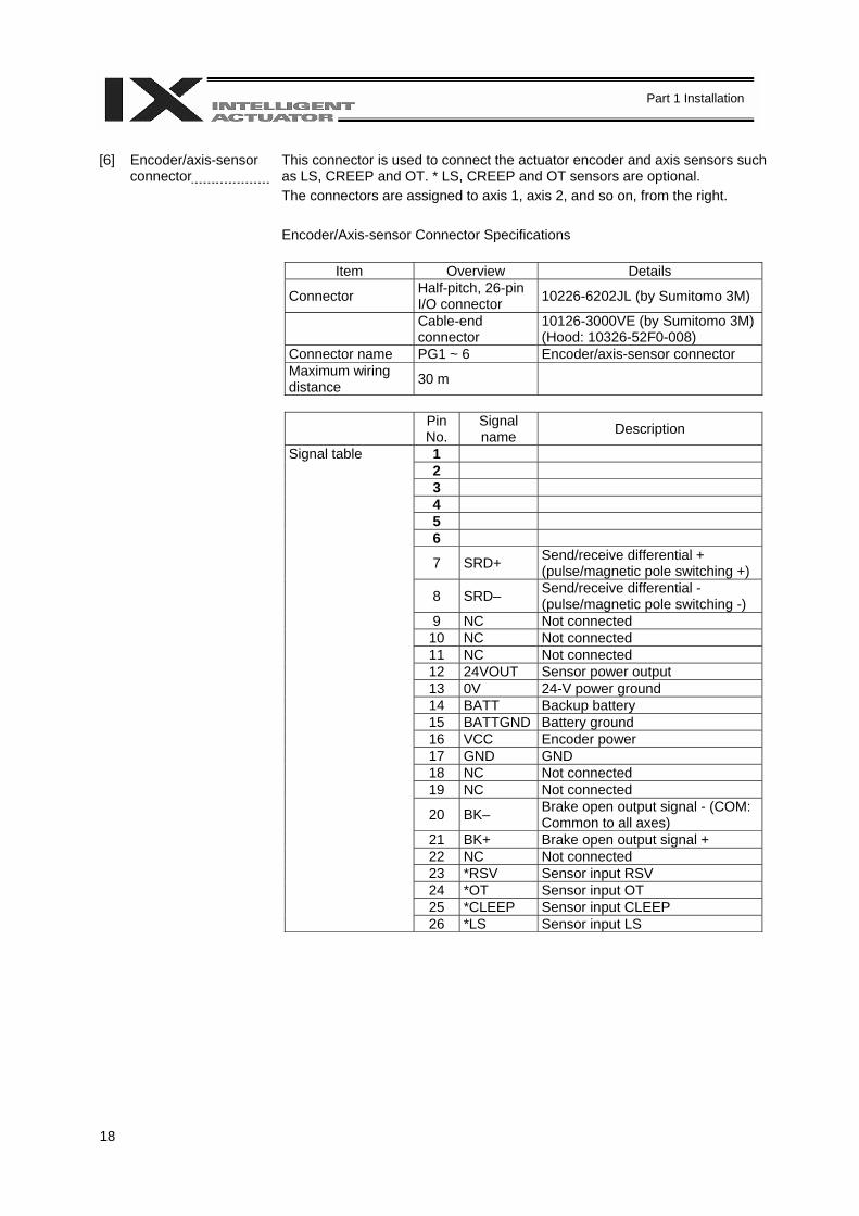
[6] Encoder/axis-sensor
connector This connector is used to connect the actuator encoder and axis sensors such as LS, CREEP and OT. * LS, CREEP and OT sensors are optional. The connectors are assigned to axis 1, axis 2, and so on, from the right. Encoder/Axis-sensor Connector Specifications
Item Overview Details
Connector Half-pitch, 26-pin I/O connector 10226-6202JL (by Sumitomo 3M)
Cable-end connector
10126-3000VE (by Sumitomo 3M) (Hood: 10326-52F0-008)
Connector name PG1 ~ 6 Encoder/axis-sensor connector Maximum wiring distance 30 m
Pin No.
Signal name Description
Signal table 1 2 3 4 5 6
7 SRD+ Send/receive differential + (pulse/magnetic pole switching +)
8 SRD– Send/receive differential - (pulse/magnetic pole switching -)
9 NC Not connected 10 NC Not connected 11 NC Not connected 12 24VOUT Sensor power output 13 0V 24-V power ground 14 BATT Backup battery 15 BATTGND Battery ground 16 VCC Encoder power 17 GND GND 18 NC Not connected 19 NC Not connected
20 BK– Brake open output signal - (COM: Common to all axes)
21 BK+ Brake open output signal + 22 NC Not connected 23 *RSV Sensor input RSV 24 *OT Sensor input OT 25 *CLEEP Sensor input CLEEP 26 *LS Sensor input LS
19
Part 1 Installation
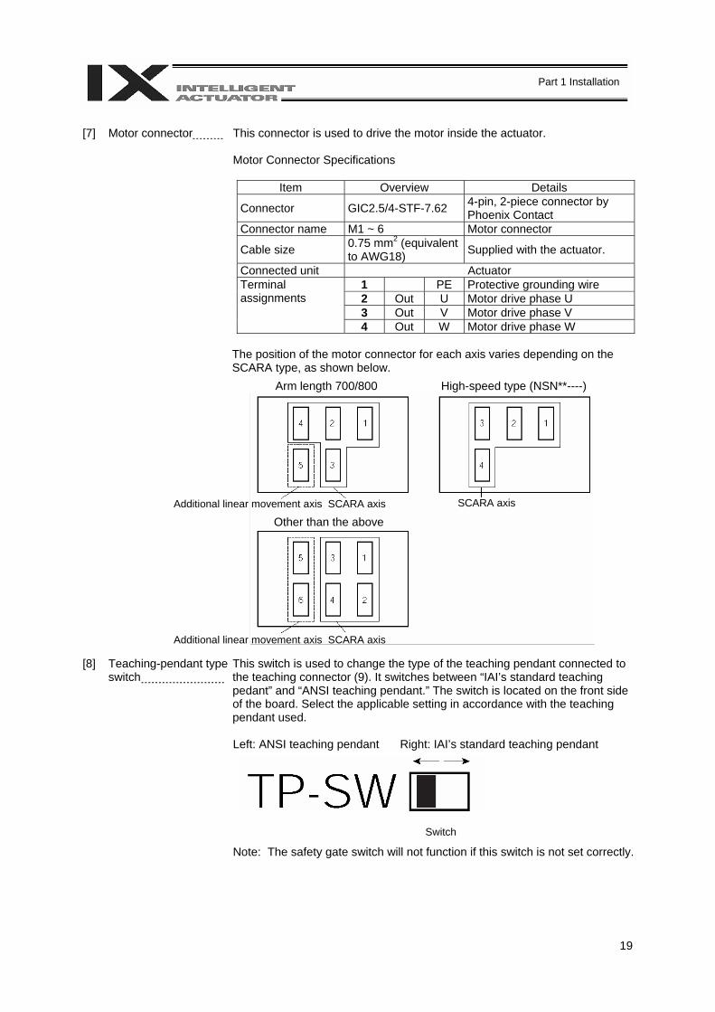
[7] Motor connector This connector is used to drive the motor inside the actuator.
Motor Connector Specifications
Item Overview Details
Connector GIC2.5/4-STF-7.62 4-pin, 2-piece connector by Phoenix Contact
Connector name M1 ~ 6 Motor connector
Cable size 0.75 mm2 (equivalent to AWG18) Supplied with the actuator.
Connected unit Actuator 1 PE Protective grounding wire Terminal
assignments 2 Out U Motor drive phase U 3 Out V Motor drive phase V 4 Out W Motor drive phase W
The position of the motor connector for each axis varies depending on the SCARA type, as shown below.
[8] Teaching-pendant type
switch This switch is used to change the type of the teaching pendant connected to the teaching connector (9). It switches between “IAI’s standard teaching pedant” and “ANSI teaching pendant.” The switch is located on the front side of the board. Select the applicable setting in accordance with the teaching pendant used. Left: ANSI teaching pendant Right: IAI’s standard teaching pendant Note: The safety gate switch will not function if this switch is not set correctly.
Switch
Arm length 700/800 High-speed type (NSN**----)
Additional linear movement axis SCARA axis SCARA axis
Additional linear movement axis SCARA axis
Other than the above
20
Part 1 Installation
[9] Teaching connector The teaching interface connects IAI’s teaching pendant or a PC to enable
operation and setting of your equipment from the teaching pendant/PC. The physical interface consists of a RS232C system based on a 25 pin D-sub connector. The signal level conforms to RS232C, and a desired baud rate (up to 115.2 kbps) can be selected depending on the program. RS232C communication is possible only when the mode switch (12) is set to the MANU position. You can also use an ANSI teaching pendant equipped with an ANSI-compliant double-action enable switch. Whether the controller supports an ANSI teaching pendant or IAI’s standard teaching pendant can be set using the selector switch (8) provided above the teaching pendant connector. Interface Specifications of Teaching Serial Interface
Item Overview Details
Connector DSUB-25 XM3B-2542-502L (by Omron) Connector name T.P. Teaching connector Communication method
RS232C-compliant, start-stop synchronous half-duplex communication
Signal assignments conform to the RS232C DTE terminal layout. Assign dedicated control lines to undefined lines, etc.
Baud rate Up to 115.2 kbps Half-duplex communication speeds of up to 115.2 kbps are supported.
Maximum wiring distance
10M At 38.4 kbps
Interface standard RS232C Connected unit Dedicated teaching
pendant IAI’s standard teaching pendant for X-SEL, or ANSI teaching pendant
Connection cable Dedicated cable Power supply 5 VDC or 24 VDC A multi-fuse (MF-R090) is installed
to protect each line against short current (the fuse will trip with currents of between 1.1 A and 2.2 A).
Protocol X-SEL teaching protocol
The connector supports the X-SEL-J/K teaching pendant interface protocol.
Emergency-stop control
Series emergency-stop relay drive (24 V)
An emergency-stop relay drive line is provided in the interface connector. This line is connected in series with other emergency-stop contact. Two independent emergency stop input circuits are provided as a redundant safety design.
Enabling control Enable switch line (24 V)
A line for connecting an enable switch is provided as an operator interlock. Two independent enable input circuits are provided as a redundant safety design.
[12] Mode switch AUTO/MANU switch Whether or not the teaching pendant can be used is set by the AUTO/MANU mode switch. The controller establishes a handshake with the teaching pendant only when this switch is set to the MANU mode. Note, however, that the teaching pendant displays the monitor screen regardless of the AUTO/MANU setting.
21
Part 1 Installation
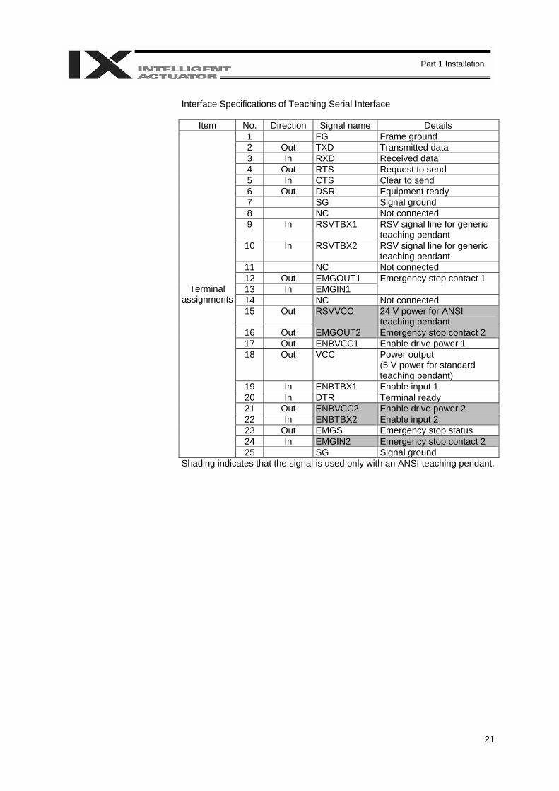
Interface Specifications of Teaching Serial Interface
Item No. Direction Signal name Details 1 FG Frame ground 2 Out TXD Transmitted data 3 In RXD Received data 4 Out RTS Request to send 5 In CTS Clear to send 6 Out DSR Equipment ready 7 SG Signal ground 8 NC Not connected 9 In RSVTBX1 RSV signal line for generic
teaching pendant 10 In RSVTBX2 RSV signal line for generic
teaching pendant 11 NC Not connected 12 Out EMGOUT1 Emergency stop contact 1 13 In EMGIN1 14 NC Not connected 15 Out RSVVCC 24 V power for ANSI
teaching pendant 16 Out EMGOUT2 Emergency stop contact 2 17 Out ENBVCC1 Enable drive power 1 18 Out VCC Power output
(5 V power for standard teaching pendant)
19 In ENBTBX1 Enable input 1 20 In DTR Terminal ready 21 Out ENBVCC2 Enable drive power 2 22 In ENBTBX2 Enable input 2 23 Out EMGS Emergency stop status 24 In EMGIN2 Emergency stop contact 2
Terminal assignments
25 SG Signal ground Shading indicates that the signal is used only with an ANSI teaching pendant.
22
Part 1 Installation
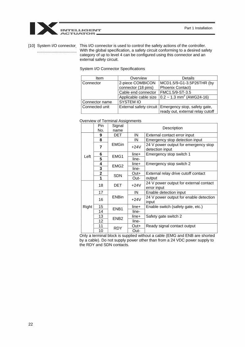
[10] System I/O connector
This I/O connector is used to control the safety actions of the controller. With the global specification, a safety circuit conforming to a desired safety category of up to level 4 can be configured using this connector and an external safety circuit. System I/O Connector Specifications
Item Overview Details
Connector 2-piece COMBICON connector (18 pins)
MCD1.5/9-G1-3.5P26THR (by Phoenix Contact)
Cable end connector FMC1.5/9-ST-3.5 Applicable cable size 0.2 ~ 1.3 mm2 (AWG24-16) Connector name SYSTEM IO Connected unit External safety circuit Emergency stop, safety gate,
ready out, external relay cutoff
Overview of Terminal Assignments
Pin No.
Signal name Description
9 DET IN External contact error input 8 IN Emergency stop detection input
7 EMGin +24V 24 V power output for emergency stop detection input
6 line+ 5 EMG1 line-
Emergency stop switch 1
4 line+ 3 EMG2 line-
Emergency stop switch 2
2 Out+
Left
1 SDN Out- External relay drive cutoff contact output
18 DET +24V 24 V power output for external contact error input
17 IN Enable detection input
16 ENBin +24V 24 V power output for enable detection input
15 line+ 14 ENB1 line-
Enable switch (safety gate, etc.)
13 line+ 12 ENB2 line-
Safety gate switch 2
11 Out+
Right
10 RDY Out- Ready signal contact output
Only a terminal block is supplied without a cable (EMG and ENB are shorted by a cable). Do not supply power other than from a 24 VDC power supply to the RDY and SDN contacts.
23
Part 1 Installation
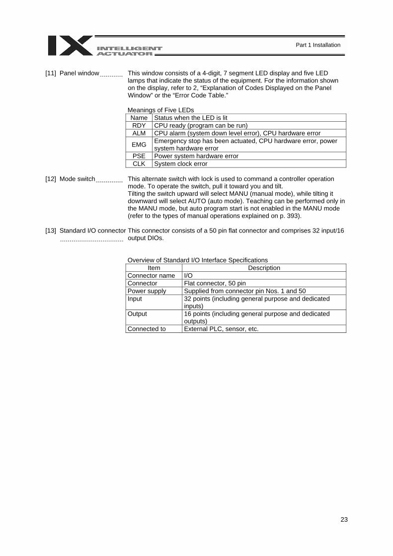
[11] Panel window This window consists of a 4-digit, 7 segment LED display and five LED
lamps that indicate the status of the equipment. For the information shown on the display, refer to 2, “Explanation of Codes Displayed on the Panel Window” or the “Error Code Table.”
Meanings of Five LEDs Name Status when the LED is lit RDY CPU ready (program can be run) ALM CPU alarm (system down level error), CPU hardware error
EMG Emergency stop has been actuated, CPU hardware error, power system hardware error
PSE Power system hardware error CLK System clock error
[12] Mode switch This alternate switch with lock is used to command a controller operation
mode. To operate the switch, pull it toward you and tilt. Tilting the switch upward will select MANU (manual mode), while tilting it downward will select AUTO (auto mode). Teaching can be performed only in the MANU mode, but auto program start is not enabled in the MANU mode (refer to the types of manual operations explained on p. 393).
[13] Standard I/O connector
This connector consists of a 50 pin flat connector and comprises 32 input/16 output DIOs.
Overview of Standard I/O Interface Specifications
Item Description Connector name I/O Connector Flat connector, 50 pin Power supply Supplied from connector pin Nos. 1 and 50 Input 32 points (including general purpose and dedicated
inputs) Output 16 points (including general purpose and dedicated
outputs) Connected to External PLC, sensor, etc.
24
Part 1 Installation
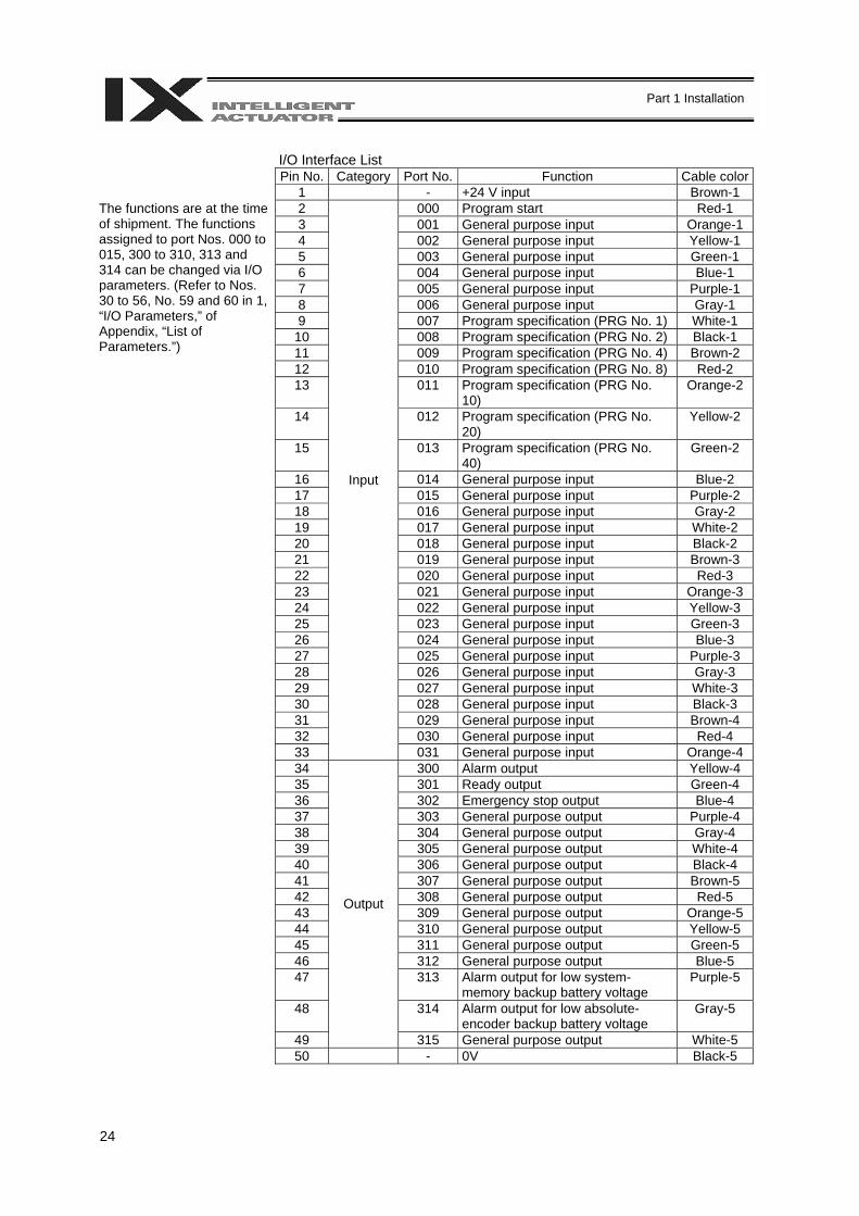
I/O Interface List
Pin No. Category Port No. Function Cable color 1 - +24 V input Brown-1
2 000 Program start Red-1 3 001 General purpose input Orange-1 4 002 General purpose input Yellow-1 5 003 General purpose input Green-1 6 004 General purpose input Blue-1 7 005 General purpose input Purple-1 8 006 General purpose input Gray-1 9 007 Program specification (PRG No. 1) White-1
10 008 Program specification (PRG No. 2) Black-1 11 009 Program specification (PRG No. 4) Brown-2
The functions are at the time of shipment. The functions assigned to port Nos. 000 to 015, 300 to 310, 313 and 314 can be changed via I/O parameters. (Refer to Nos. 30 to 56, No. 59 and 60 in 1, “I/O Parameters,” of Appendix, “List of Parameters.”)
12 010 Program specification (PRG No. 8) Red-2 13 011 Program specification (PRG No.
10) Orange-2
14 012 Program specification (PRG No. 20)
Yellow-2
15 013 Program specification (PRG No. 40)
Green-2
16 014 General purpose input Blue-2 17 015 General purpose input Purple-2 18 016 General purpose input Gray-2 19 017 General purpose input White-2 20 018 General purpose input Black-2 21 019 General purpose input Brown-3 22 020 General purpose input Red-3 23 021 General purpose input Orange-3 24 022 General purpose input Yellow-3 25 023 General purpose input Green-3 26 024 General purpose input Blue-3 27 025 General purpose input Purple-3 28 026 General purpose input Gray-3 29 027 General purpose input White-3 30 028 General purpose input Black-3 31 029 General purpose input Brown-4 32 030 General purpose input Red-4 33
Input
031 General purpose input Orange-4 34 300 Alarm output Yellow-4 35 301 Ready output Green-4 36 302 Emergency stop output Blue-4 37 303 General purpose output Purple-4 38 304 General purpose output Gray-4 39 305 General purpose output White-4 40 306 General purpose output Black-4 41 307 General purpose output Brown-5 42 308 General purpose output Red-5 43 309 General purpose output Orange-5 44 310 General purpose output Yellow-5 45 311 General purpose output Green-5 46 312 General purpose output Blue-5 47 313 Alarm output for low system-
memory backup battery voltage Purple-5
48 314 Alarm output for low absolute-encoder backup battery voltage
Gray-5
49
Output
315 General purpose output White-5 50 - 0V Black-5
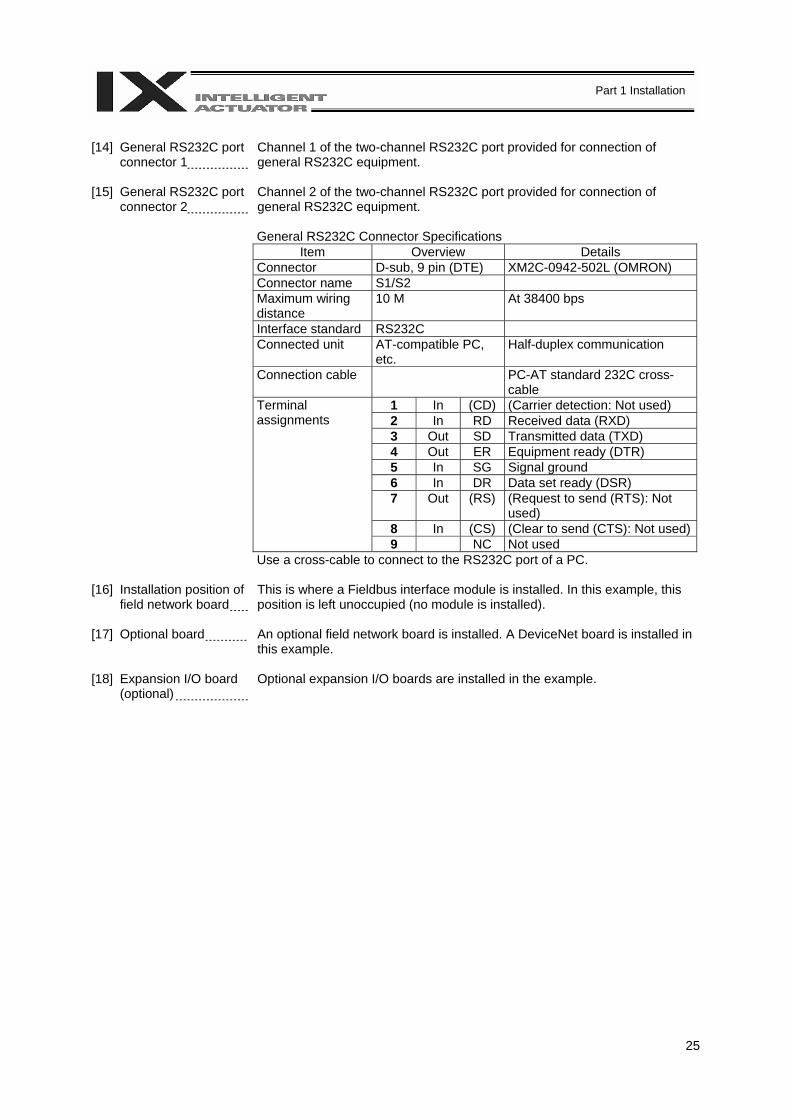
25
Part 1 Installation
[14] General RS232C port
connector 1 Channel 1 of the two-channel RS232C port provided for connection of general RS232C equipment.
[15] General RS232C port connector 2
Channel 2 of the two-channel RS232C port provided for connection of general RS232C equipment. General RS232C Connector Specifications
Item Overview Details Connector D-sub, 9 pin (DTE) XM2C-0942-502L (OMRON) Connector name S1/S2 Maximum wiring distance
10 M At 38400 bps
Interface standard RS232C Connected unit AT-compatible PC,
etc. Half-duplex communication
Connection cable PC-AT standard 232C cross-cable
1 In (CD) (Carrier detection: Not used) Terminal assignments 2 In RD Received data (RXD) 3 Out SD Transmitted data (TXD) 4 Out ER Equipment ready (DTR) 5 In SG Signal ground 6 In DR Data set ready (DSR) 7 Out (RS) (Request to send (RTS): Not
used) 8 In (CS) (Clear to send (CTS): Not used) 9 NC Not used Use a cross-cable to connect to the RS232C port of a PC.
[16] Installation position of
field network board This is where a Fieldbus interface module is installed. In this example, this position is left unoccupied (no module is installed).
[17] Optional board An optional field network board is installed. A DeviceNet board is installed in this example.
[18] Expansion I/O board (optional)
Optional expansion I/O boards are installed in the example.
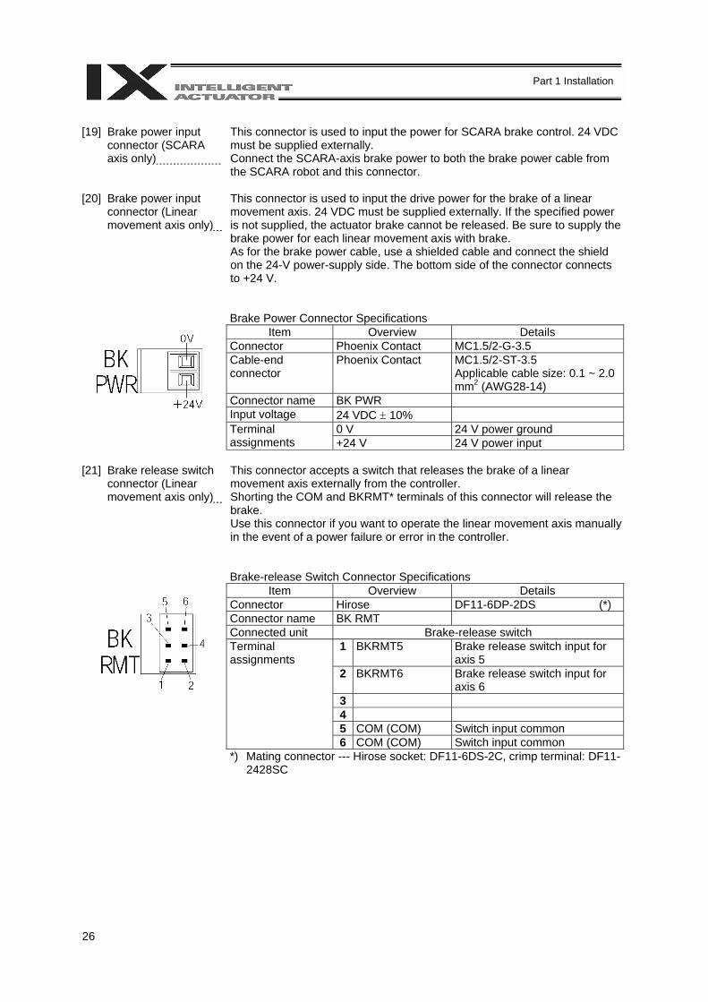
26
Part 1 Installation
[19] Brake power input
connector (SCARA axis only)
This connector is used to input the power for SCARA brake control. 24 VDC must be supplied externally. Connect the SCARA-axis brake power to both the brake power cable from the SCARA robot and this connector.
[20] Brake power input connector (Linear movement axis only)
This connector is used to input the drive power for the brake of a linear movement axis. 24 VDC must be supplied externally. If the specified power is not supplied, the actuator brake cannot be released. Be sure to supply the brake power for each linear movement axis with brake. As for the brake power cable, use a shielded cable and connect the shield on the 24-V power-supply side. The bottom side of the connector connects to +24 V.
Brake Power Connector Specifications
Item Overview Details Connector Phoenix Contact MC1.5/2-G-3.5 Cable-end connector
Phoenix Contact MC1.5/2-ST-3.5 Applicable cable size: 0.1 ~ 2.0 mm2 (AWG28-14)
Connector name BK PWR Input voltage 24 VDC ± 10%
0 V 24 V power ground Terminal assignments +24 V 24 V power input
[21] Brake release switch
connector (Linear movement axis only)
This connector accepts a switch that releases the brake of a linear movement axis externally from the controller. Shorting the COM and BKRMT* terminals of this connector will release the brake. Use this connector if you want to operate the linear movement axis manually in the event of a power failure or error in the controller.
Brake-release Switch Connector Specifications
Item Overview Details Connector Hirose DF11-6DP-2DS (*) Connector name BK RMT Connected unit Brake-release switch
1 BKRMT5 Brake release switch input for axis 5
Terminal assignments
2 BKRMT6 Brake release switch input for axis 6
3 4 5 COM (COM) Switch input common 6 COM (COM) Switch input common *) Mating connector --- Hirose socket: DF11-6DS-2C, crimp terminal: DF11-
2428SC

27
Part 1 Installation
[22] Brake switch (Linear
movement axis only) This alternate switch with lock is used to release the axis brake. To operate the switch, pull it toward you and tilt. Tilting the switch upward (RLS side) will release the brake forcibly, while tilting it downward (NOM) will enable the controller to release the brake. Note: The SCARA-axis brake switch is located on the panel of the SCARA
robot.
[23] Conveyor tracking connector
This connector is used only when the controller is of conveyor tracking specification. Normally this connector is not used.
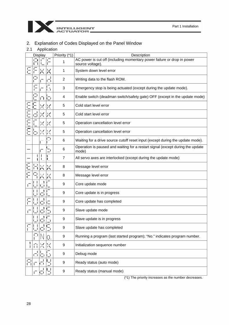
28
Part 1 Installation
2. Explanation of Codes Displayed on the Panel Window 2.1 Application
Display Priority (*1) Description
1 AC power is cut off (including momentary power failure or drop in power source voltage).
1 System down level error
2 Writing data to the flash ROM.
3 Emergency stop is being actuated (except during the update mode).
4 Enable switch (deadman switch/safety gate) OFF (except in the update mode)
5 Cold start level error
5 Cold start level error
5 Operation cancellation level error
5 Operation cancellation level error
6 Waiting for a drive source cutoff reset input (except during the update mode).
6 Operation is paused and waiting for a restart signal (except during the update mode)
7 All servo axes are interlocked (except during the update mode)
8 Message level error
8 Message level error
9 Core update mode
9 Core update is in progress
9 Core update has completed
9 Slave update mode
9 Slave update is in progress
9 Slave update has completed
9 Running a program (last started program); “No.” indicates program number.
9 Initialization sequence number
9 Debug mode
9 Ready status (auto mode)
9 Ready status (manual mode)
(*1) The priority increases as the number decreases.
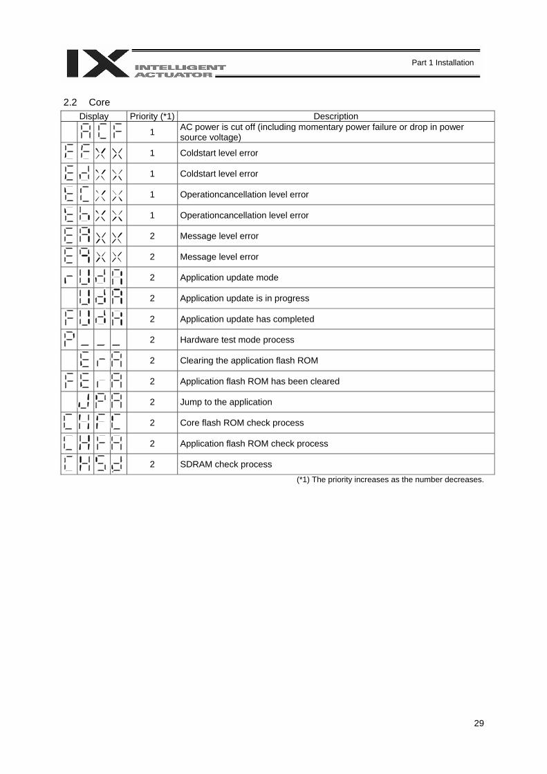
29
Part 1 Installation
2.2 Core
Display Priority (*1) Description
1 AC power is cut off (including momentary power failure or drop in power source voltage)
1 Coldstart level error
1 Coldstart level error
1 Operationcancellation level error
1 Operationcancellation level error
2 Message level error
2 Message level error
2 Application update mode
2 Application update is in progress
2 Application update has completed
2 Hardware test mode process
2 Clearing the application flash ROM
2 Application flash ROM has been cleared
2 Jump to the application
2 Core flash ROM check process
2 Application flash ROM check process
2 SDRAM check process
(*1) The priority increases as the number decreases.

30
Part 1 Installation
2.3 Current Monitor and Variable Monitor Other parameter Nos. 49 and 50 can be set up to monitor currents or variables on the panel window. (1) Current monitor Currents of up to four axes having continuous axis numbers can be monitored. Parameter settings Other parameter No. 49 = 1 Other parameter No. 50 = Smallest axis number among the axes to be monitored Example) If other parameter No. 49 is set to “1” and other parameter No. 50 to “3” for a 6 axis controller,
the far right segment digit will show the current for axis 3.
Axis 6 Axis 5 Axis 4 Axis 3
When data is written to the flash ROM or a software reset (restart) is executed after the parameter values have been input, the panel window will show the motor current to rating ratio (%) by a segment pattern, instead of “ready status” or “program run number.” The segment display patterns and corresponding motor current to rating ratios (%) are shown below.
Thick lines indicate illuminated segments.
0 < Motor current to rating ratio (%) ≤ 25
25 < Motor current to rating ratio (%) ≤ 50
50 < Motor current to rating ratio (%) ≤ 75
75 < Motor current to rating ratio (%) ≤ 100
100 < Motor current to rating ratio (%) ≤ 150
150 < Motor current to rating ratio (%) ≤ 200
200 < Motor current to rating ratio (%)

31
Part 1 Installation
(2) Variable monitor The contents of global integer variables can be displayed on the panel window. Positive integers of 1 to 999 can be displayed. Parameter settings Other parameter No. 49 = 2 Other parameter No. 50 = Variable number of the global integer variable to be monitored When data is written to the flash ROM or a software reset (restart) is executed after the parameter values have been input, the panel window will show the content of the global integer variable, instead of “ready status” or “program run number.” The far-left segment digit should read “U.”
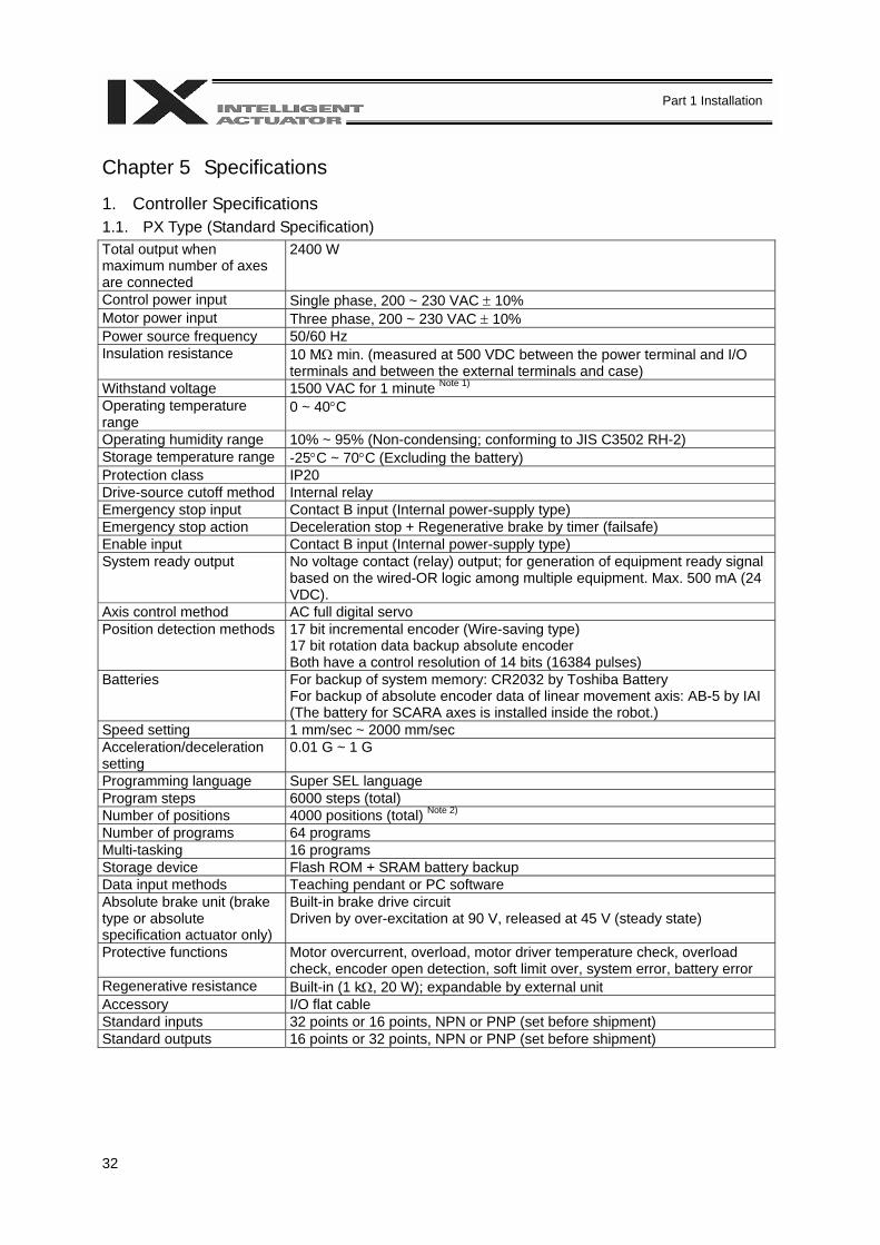
32
Part 1 Installation
Chapter 5 Specifications 1. Controller Specifications 1.1. PX Type (Standard Specification) Total output when maximum number of axes are connected
2400 W
Control power input Single phase, 200 ~ 230 VAC ± 10% Motor power input Three phase, 200 ~ 230 VAC ± 10% Power source frequency 50/60 Hz Insulation resistance 10 MΩ min. (measured at 500 VDC between the power terminal and I/O
terminals and between the external terminals and case) Withstand voltage 1500 VAC for 1 minute Note 1) Operating temperature range
0 ~ 40°C
Operating humidity range 10% ~ 95% (Non-condensing; conforming to JIS C3502 RH-2) Storage temperature range -25°C ~ 70°C (Excluding the battery) Protection class IP20 Drive-source cutoff method Internal relay Emergency stop input Contact B input (Internal power-supply type) Emergency stop action Deceleration stop + Regenerative brake by timer (failsafe) Enable input Contact B input (Internal power-supply type) System ready output No voltage contact (relay) output; for generation of equipment ready signal
based on the wired-OR logic among multiple equipment. Max. 500 mA (24 VDC).
Axis control method AC full digital servo Position detection methods 17 bit incremental encoder (Wire-saving type)
17 bit rotation data backup absolute encoder Both have a control resolution of 14 bits (16384 pulses)
Batteries For backup of system memory: CR2032 by Toshiba Battery For backup of absolute encoder data of linear movement axis: AB-5 by IAI (The battery for SCARA axes is installed inside the robot.)
Speed setting 1 mm/sec ~ 2000 mm/sec Acceleration/deceleration setting
0.01 G ~ 1 G
Programming language Super SEL language Program steps 6000 steps (total) Number of positions 4000 positions (total) Note 2) Number of programs 64 programs Multi-tasking 16 programs Storage device Flash ROM + SRAM battery backup Data input methods Teaching pendant or PC software Absolute brake unit (brake type or absolute specification actuator only)
Built-in brake drive circuit Driven by over-excitation at 90 V, released at 45 V (steady state)
Protective functions Motor overcurrent, overload, motor driver temperature check, overload check, encoder open detection, soft limit over, system error, battery error
Regenerative resistance Built-in (1 kΩ, 20 W); expandable by external unit Accessory I/O flat cable Standard inputs 32 points or 16 points, NPN or PNP (set before shipment) Standard outputs 16 points or 32 points, NPN or PNP (set before shipment)
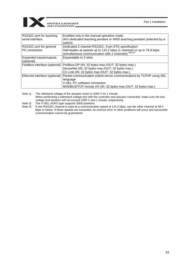
33
Part 1 Installation
RS232C port for teaching serial interface
Enabled only in the manual operation mode. IAI’s dedicated teaching pendant or ANSI teaching pendant (selected by a switch)
RS232C port for general PC connection
Dedicated 2 channel RS232C, 9 pin DTE specification Half-duplex at speeds up to 115.2 kbps (1 channel) or up to 76.8 kbps (simultaneous communication with 2 channels) Note 3)
Expanded inputs/outputs (optional)
Expandable to 3 slots
Fieldbus interface (optional) Profibus-DP (IN: 32 bytes max./OUT: 32 bytes max.) DeviceNet (IN: 32 bytes max./OUT: 32 bytes max.) CC-Link (IN: 32 bytes max./OUT: 32 bytes max.)
Ethernet interface (optional) Packet communication (client-server communication) by TCP/IP using SEL language X-SEL PC software connection MODBUS/TCP remote I/O (IN: 32 bytes max./OUT: 32 bytes max.)
Note 1) The withstand voltage of the actuator motor is 1000 V for 1 minute.
When performing a withstand voltage test with the controller and actuator connected, make sure the test voltage and duration will not exceed 1000 V and 1 minute, respectively.
Note 2) The X-SEL-JX/KX type supports 3000 positions. Note 3) If one RS232C channel is used at a communication speed of 115.2 kbps, use the other channel at 38.4
kbps or below. If these speeds are exceeded, an overrun error or other problems will occur and successful communication cannot be guaranteed.
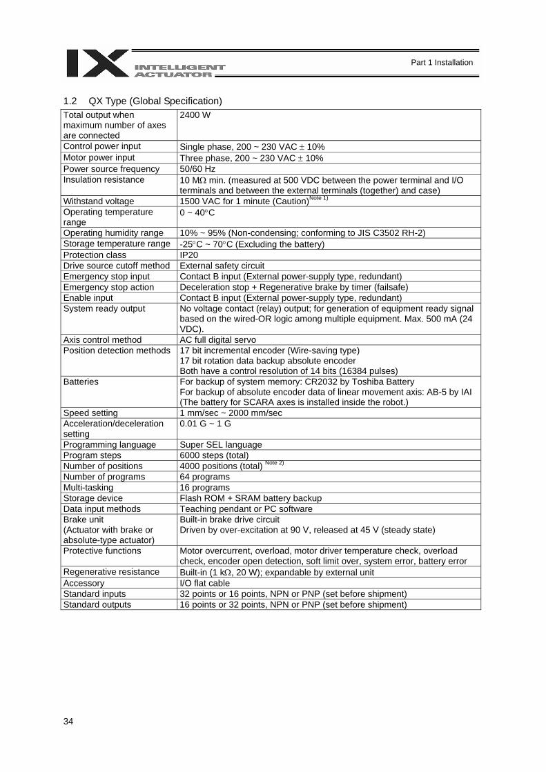
34
Part 1 Installation
1.2 QX Type (Global Specification) Total output when maximum number of axes are connected
2400 W
Control power input Single phase, 200 ~ 230 VAC ± 10% Motor power input Three phase, 200 ~ 230 VAC ± 10% Power source frequency 50/60 Hz Insulation resistance 10 MΩ min. (measured at 500 VDC between the power terminal and I/O
terminals and between the external terminals (together) and case) Withstand voltage 1500 VAC for 1 minute (Caution)Note 1) Operating temperature range
0 ~ 40°C
Operating humidity range 10% ~ 95% (Non-condensing; conforming to JIS C3502 RH-2) Storage temperature range -25°C ~ 70°C (Excluding the battery) Protection class IP20 Drive source cutoff method External safety circuit Emergency stop input Contact B input (External power-supply type, redundant) Emergency stop action Deceleration stop + Regenerative brake by timer (failsafe) Enable input Contact B input (External power-supply type, redundant) System ready output No voltage contact (relay) output; for generation of equipment ready signal
based on the wired-OR logic among multiple equipment. Max. 500 mA (24 VDC).
Axis control method AC full digital servo Position detection methods 17 bit incremental encoder (Wire-saving type)
17 bit rotation data backup absolute encoder Both have a control resolution of 14 bits (16384 pulses)
Batteries For backup of system memory: CR2032 by Toshiba Battery For backup of absolute encoder data of linear movement axis: AB-5 by IAI (The battery for SCARA axes is installed inside the robot.)
Speed setting 1 mm/sec ~ 2000 mm/sec Acceleration/deceleration setting
0.01 G ~ 1 G
Programming language Super SEL language Program steps 6000 steps (total) Number of positions 4000 positions (total) Note 2) Number of programs 64 programs Multi-tasking 16 programs Storage device Flash ROM + SRAM battery backup Data input methods Teaching pendant or PC software Brake unit (Actuator with brake or absolute-type actuator)
Built-in brake drive circuit Driven by over-excitation at 90 V, released at 45 V (steady state)
Protective functions Motor overcurrent, overload, motor driver temperature check, overload check, encoder open detection, soft limit over, system error, battery error
Regenerative resistance Built-in (1 kΩ, 20 W); expandable by external unit Accessory I/O flat cable Standard inputs 32 points or 16 points, NPN or PNP (set before shipment) Standard outputs 16 points or 32 points, NPN or PNP (set before shipment)
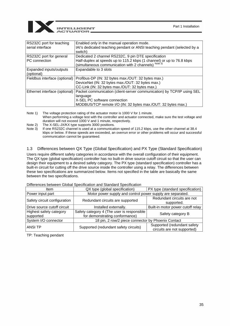
35
Part 1 Installation
RS232C port for teaching serial interface
Enabled only in the manual operation mode. IAI’s dedicated teaching pendant or ANSI teaching pendant (selected by a switch)
RS232C port for general PC connection
Dedicated 2 channel RS232C, 9 pin DTE specification Half-duplex at speeds up to 115.2 kbps (1 channel) or up to 76.8 kbps (simultaneous communication with 2 channels) Note 3)
Expanded inputs/outputs (optional)
Expandable to 3 slots
Fieldbus interface (optional) Profibus-DP (IN: 32 bytes max./OUT: 32 bytes max.) DeviceNet (IN: 32 bytes max./OUT: 32 bytes max.) CC-Link (IN: 32 bytes max./OUT: 32 bytes max.)
Ethernet interface (optional) Packet communication (client-server communication) by TCP/IP using SEL language X-SEL PC software connection MODBUS/TCP remote I/O (IN: 32 bytes max./OUT: 32 bytes max.)
Note 1) The voltage protection rating of the actuator motor is 1000 V for 1 minute.
When performing a voltage test with the controller and actuator connected, make sure the test voltage and duration will not exceed 1000 V and 1 minute, respectively.
Note 2) The X-SEL-JX/KX type supports 3000 positions. Note 3) If one RS232C channel is used at a communication speed of 115.2 kbps, use the other channel at 38.4
kbps or below. If these speeds are exceeded, an overrun error or other problems will occur and successful communication cannot be guaranteed.
1.3 Differences between QX Type (Global Specification) and PX Type (Standard Specification) Users require different safety categories in accordance with the overall configuration of their equipment. The QX type (global specification) controller has no built-in drive source cutoff circuit so that the user can design their equipment to a desired safety category. The PX type (standard specification) controller has a built-in circuit for cutting off the drive source inside the controller using a relay. The differences between these two specifications are summarized below. Items not specified in the table are basically the same between the two specifications. Differences between Global Specification and Standard Specification
Item QX type (global specification) PX type (standard specification)Power input part Motor power supply and control power supply are separated.
Safety circuit configuration Redundant circuits are supported Redundant circuits are not supported.
Drive source cutoff circuit Installed externally. Built-in motor power cutoff relayHighest safety category supported
Safety category 4 (The user is responsible for demonstrating conformance) Safety category B
System I/O connector 18 pin, 2 row/2 piece connector by Phoenix Contact
ANSI TP Supported (redundant safety circuits) Supported (redundant safety circuits are not supported)
TP: Teaching pendant
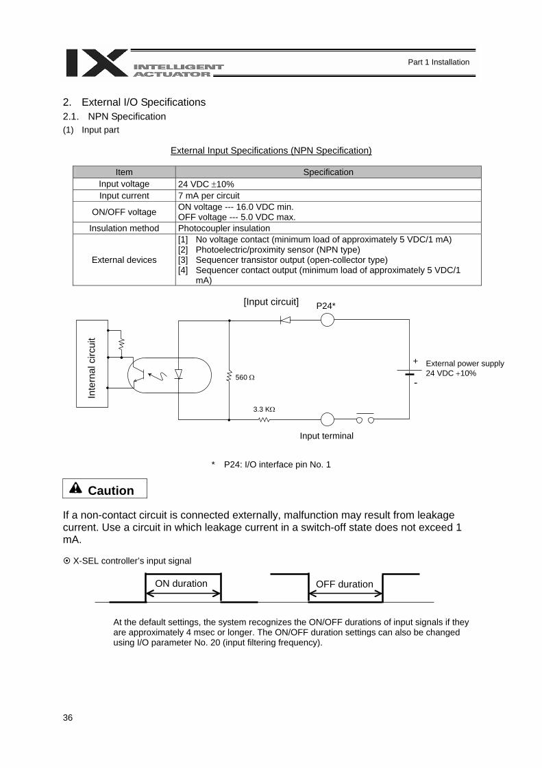
36
Part 1 Installation
2. External I/O Specifications 2.1. NPN Specification (1) Input part
External Input Specifications (NPN Specification)
Item Specification Input voltage 24 VDC ±10% Input current 7 mA per circuit
ON/OFF voltage ON voltage --- 16.0 VDC min. OFF voltage --- 5.0 VDC max.
Insulation method Photocoupler insulation
External devices
[1] No voltage contact (minimum load of approximately 5 VDC/1 mA) [2] Photoelectric/proximity sensor (NPN type) [3] Sequencer transistor output (open-collector type) [4] Sequencer contact output (minimum load of approximately 5 VDC/1
mA)
[Input circuit]
* P24: I/O interface pin No. 1
Caution If a non-contact circuit is connected externally, malfunction may result from leakage current. Use a circuit in which leakage current in a switch-off state does not exceed 1 mA.
X-SEL controller’s input signal
At the default settings, the system recognizes the ON/OFF durations of input signals if they are approximately 4 msec or longer. The ON/OFF duration settings can also be changed using I/O parameter No. 20 (input filtering frequency).
Inte
rnal
circ
uit
Input terminal
External power supply 24 VDC +10%
ON duration OFF duration
P24*
+
- 560 Ω
3.3 KΩ

37
Part 1 Installation
(2) Output part
External Output Specifications (NPN Specification)
Item Specification Load voltage 24 VDC
Maximum load current 100 mA per point, 400 mA per 8 ports Note) Leakage current 0.1 mA max. per point
TD62084 (or equivalent)
Insulation method Photocoupler insulation
External devices [1] Miniature relay [2] Sequencer input unit
Note) 400 mA is the maximum total load current of every eight ports from output port No. 300 (the maximum total load current of output port No. 300 + n to No. 300 + n + 7 is 400 mA, where n is 0 or a multiple of 8).
[Output circuit]
* P24: I/O interface pin No. 1 * N: I/O interface pin No. 50
Caution In the event that the load is short-circuited, the overcurrent protection circuit will cut the power. However, give due consideration to the circuit connection layout to prevent a short-circuit or overcurrent.
Inte
rnal
circ
uit
10 Ω
N*
D
P24*
+
-
Surge absorber
Output terminal
Load
External power supply 24 VDC ± 10%
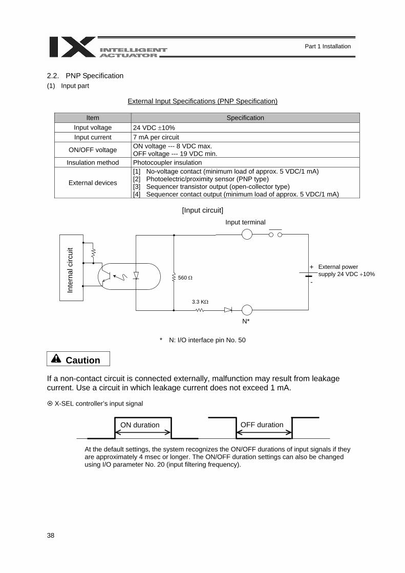
38
Part 1 Installation
2.2. PNP Specification (1) Input part
External Input Specifications (PNP Specification)
Item Specification Input voltage 24 VDC ±10% Input current 7 mA per circuit
ON/OFF voltage ON voltage --- 8 VDC max. OFF voltage --- 19 VDC min.
Insulation method Photocoupler insulation
External devices
[1] No-voltage contact (minimum load of approx. 5 VDC/1 mA) [2] Photoelectric/proximity sensor (PNP type) [3] Sequencer transistor output (open-collector type) [4] Sequencer contact output (minimum load of approx. 5 VDC/1 mA)
[Input circuit]
* N: I/O interface pin No. 50
Caution If a non-contact circuit is connected externally, malfunction may result from leakage current. Use a circuit in which leakage current does not exceed 1 mA.
X-SEL controller’s input signal
At the default settings, the system recognizes the ON/OFF durations of input signals if they are approximately 4 msec or longer. The ON/OFF duration settings can also be changed using I/O parameter No. 20 (input filtering frequency).
Inte
rnal
circ
uit
Input terminal
External power supply 24 VDC +10%
N*
560 Ω
3.3 KΩ
ON duration OFF duration
+
-
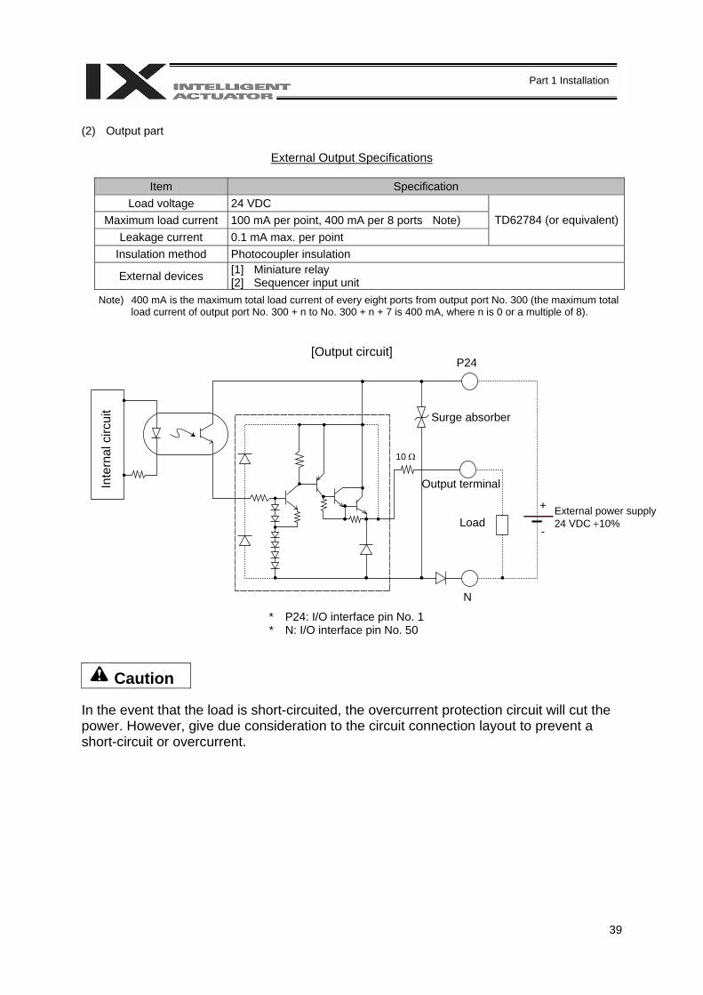
39
Part 1 Installation
(2) Output part
External Output Specifications
Item Specification Load voltage 24 VDC
Maximum load current 100 mA per point, 400 mA per 8 ports Note) Leakage current 0.1 mA max. per point
TD62784 (or equivalent)
Insulation method Photocoupler insulation
External devices [1] Miniature relay [2] Sequencer input unit
Note) 400 mA is the maximum total load current of every eight ports from output port No. 300 (the maximum total load current of output port No. 300 + n to No. 300 + n + 7 is 400 mA, where n is 0 or a multiple of 8).
[Output circuit]
* P24: I/O interface pin No. 1 * N: I/O interface pin No. 50
Caution In the event that the load is short-circuited, the overcurrent protection circuit will cut the power. However, give due consideration to the circuit connection layout to prevent a short-circuit or overcurrent.
Inte
rnal
circ
uit
10 Ω
N
P24
Surge absorber
Output terminal
Load External power supply 24 VDC +10%
+
-
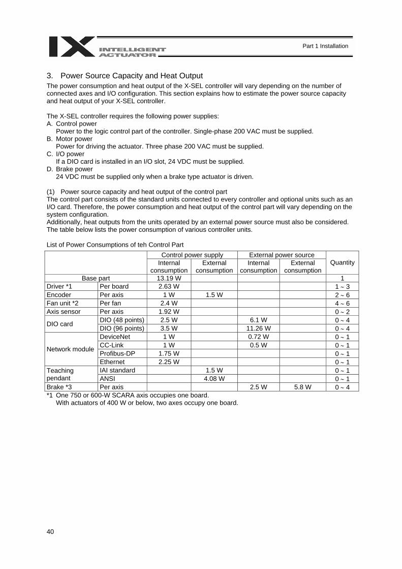
40
Part 1 Installation
3. Power Source Capacity and Heat Output The power consumption and heat output of the X-SEL controller will vary depending on the number of connected axes and I/O configuration. This section explains how to estimate the power source capacity and heat output of your X-SEL controller. The X-SEL controller requires the following power supplies: A. Control power
Power to the logic control part of the controller. Single-phase 200 VAC must be supplied. B. Motor power
Power for driving the actuator. Three phase 200 VAC must be supplied. C. I/O power
If a DIO card is installed in an I/O slot, 24 VDC must be supplied. D. Brake power
24 VDC must be supplied only when a brake type actuator is driven. (1) Power source capacity and heat output of the control part The control part consists of the standard units connected to every controller and optional units such as an I/O card. Therefore, the power consumption and heat output of the control part will vary depending on the system configuration. Additionally, heat outputs from the units operated by an external power source must also be considered. The table below lists the power consumption of various controller units. List of Power Consumptions of teh Control Part
Control power supply External power source Internal
consumptionExternal
consumption Internal
consumptionExternal
consumption Quantity
Base part 13.19 W 1 Driver *1 Per board 2.63 W 1 ∼ 3 Encoder Per axis 1 W 1.5 W 2 ∼ 6 Fan unit *2 Per fan 2.4 W 4 ∼ 6 Axis sensor Per axis 1.92 W 0 ∼ 2
DIO (48 points) 2.5 W 6.1 W 0 ∼ 4 DIO card DIO (96 points) 3.5 W 11.26 W 0 ∼ 4 DeviceNet 1 W 0.72 W 0 ∼ 1 CC-Link 1 W 0.5 W 0 ∼ 1 Profibus-DP 1.75 W 0 ∼ 1
Network module
Ethernet 2.25 W 0 ∼ 1 IAI standard 1.5 W 0 ∼ 1 Teaching
pendant ANSI 4.08 W 0 ∼ 1 Brake *3 Per axis 2.5 W 5.8 W 0 ∼ 4 *1 One 750 or 600-W SCARA axis occupies one board.
With actuators of 400 W or below, two axes occupy one board.
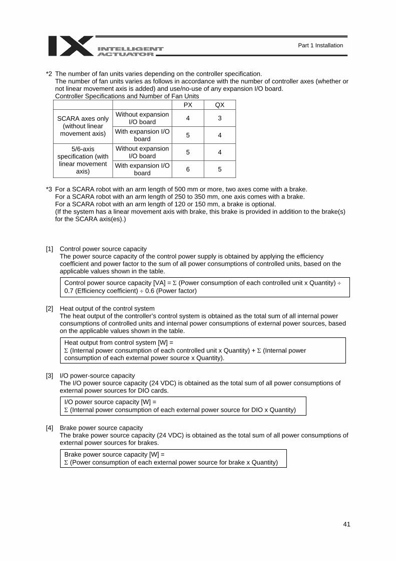
41
Part 1 Installation
*2 The number of fan units varies depending on the controller specification.
The number of fan units varies as follows in accordance with the number of controller axes (whether or not linear movement axis is added) and use/no-use of any expansion I/O board. Controller Specifications and Number of Fan Units
PX QX Without expansion
I/O board 4 3 SCARA axes only (without linear
movement axis) With expansion I/O board 5 4
Without expansion I/O board 5 4 5/6-axis
specification (with linear movement
axis) With expansion I/O
board 6 5
*3 For a SCARA robot with an arm length of 500 mm or more, two axes come with a brake.
For a SCARA robot with an arm length of 250 to 350 mm, one axis comes with a brake. For a SCARA robot with an arm length of 120 or 150 mm, a brake is optional. (If the system has a linear movement axis with brake, this brake is provided in addition to the brake(s) for the SCARA axis(es).)
[1] Control power source capacity
The power source capacity of the control power supply is obtained by applying the efficiency coefficient and power factor to the sum of all power consumptions of controlled units, based on the applicable values shown in the table.
[2] Heat output of the control system
The heat output of the controller’s control system is obtained as the total sum of all internal power consumptions of controlled units and internal power consumptions of external power sources, based on the applicable values shown in the table.
[3] I/O power-source capacity
The I/O power source capacity (24 VDC) is obtained as the total sum of all power consumptions of external power sources for DIO cards.
[4] Brake power source capacity
The brake power source capacity (24 VDC) is obtained as the total sum of all power consumptions of external power sources for brakes.
Control power source capacity [VA] = Σ (Power consumption of each controlled unit x Quantity) ÷ 0.7 (Efficiency coefficient) ÷ 0.6 (Power factor)
Heat output from control system [W] = Σ (Internal power consumption of each controlled unit x Quantity) + Σ (Internal power consumption of each external power source x Quantity).
I/O power source capacity [W] = Σ (Internal power consumption of each external power source for DIO x Quantity)
Brake power source capacity [W] = Σ (Power consumption of each external power source for brake x Quantity)
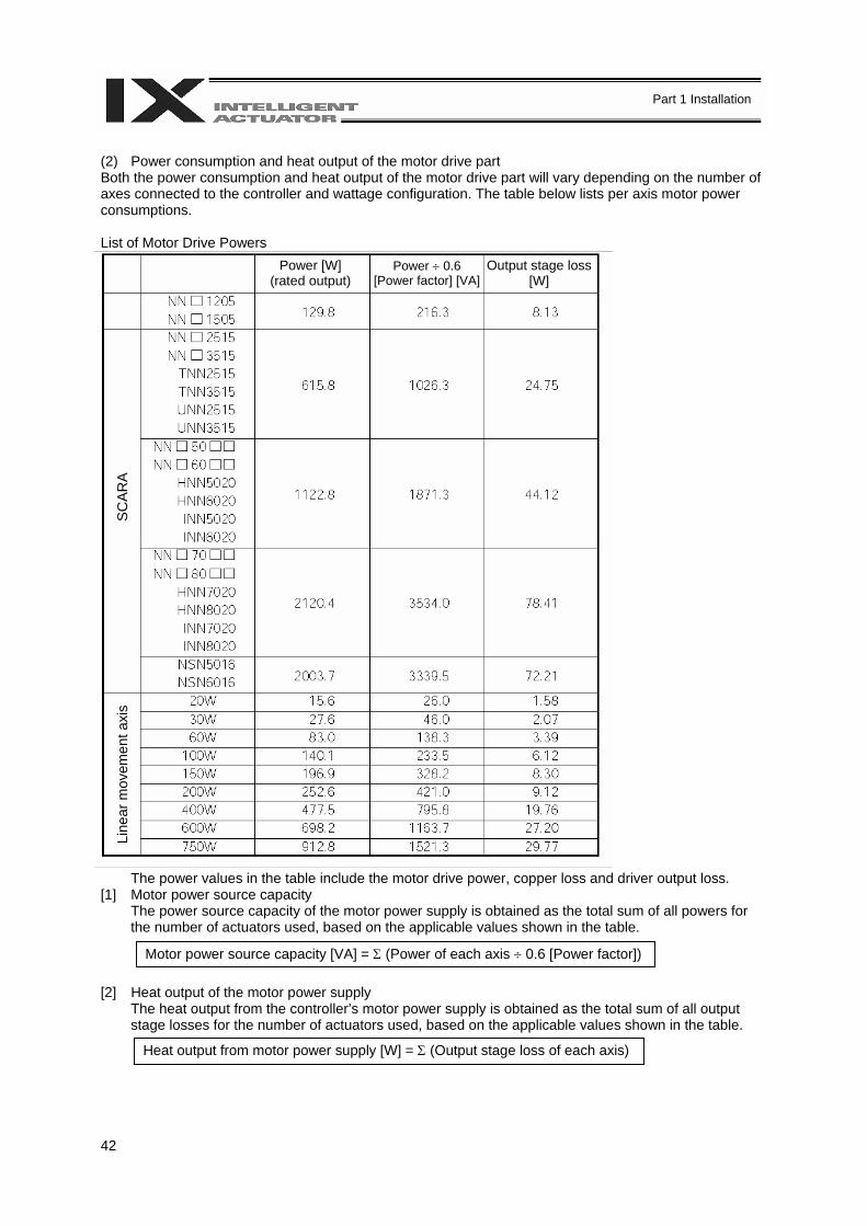
42
Part 1 Installation
(2) Power consumption and heat output of the motor drive part Both the power consumption and heat output of the motor drive part will vary depending on the number of axes connected to the controller and wattage configuration. The table below lists per axis motor power consumptions. List of Motor Drive Powers
The power values in the table include the motor drive power, copper loss and driver output loss. [1] Motor power source capacity
The power source capacity of the motor power supply is obtained as the total sum of all powers for the number of actuators used, based on the applicable values shown in the table.
[2] Heat output of the motor power supply
The heat output from the controller’s motor power supply is obtained as the total sum of all output stage losses for the number of actuators used, based on the applicable values shown in the table.
Motor power source capacity [VA] = Σ (Power of each axis ÷ 0.6 [Power factor])
Heat output from motor power supply [W] = Σ (Output stage loss of each axis)
Power [W] (rated output)
Power ÷ 0.6 [Power factor] [VA]
Output stage loss [W]
SCAR
A Li
near
mov
emen
t axi
s
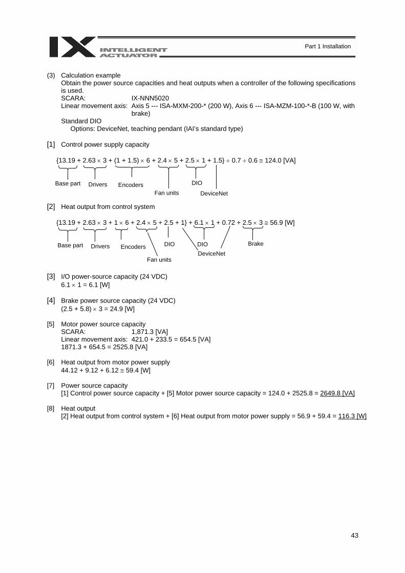
43
Part 1 Installation
(3) Calculation example
Obtain the power source capacities and heat outputs when a controller of the following specifications is used. SCARA: IX-NNN5020 Linear movement axis: Axis 5 --- ISA-MXM-200-* (200 W), Axis 6 --- ISA-MZM-100-*-B (100 W, with
brake) Standard DIO
Options: DeviceNet, teaching pendant (IAI’s standard type) [1] Control power supply capacity
13.19 + 2.63 × 3 + (1 + 1.5) × 6 + 2.4 × 5 + 2.5 × 1 + 1.5 ÷ 0.7 ÷ 0.6 ≅ 124.0 [VA] [2] Heat output from control system
13.19 + 2.63 × 3 + 1 × 6 + 2.4 × 5 + 2.5 + 1 + 6.1 × 1 + 0.72 + 2.5 × 3 ≅ 56.9 [W] [3] I/O power-source capacity (24 VDC)
6.1 × 1 = 6.1 [W] [4] Brake power source capacity (24 VDC)
(2.5 + 5.8) × 3 = 24.9 [W] [5] Motor power source capacity
SCARA: 1,871.3 [VA] Linear movement axis: 421.0 + 233.5 = 654.5 [VA] 1871.3 + 654.5 = 2525.8 [VA]
[6] Heat output from motor power supply
44.12 + 9.12 + 6.12 ≅ 59.4 [W] [7] Power source capacity
[1] Control power source capacity + [5] Motor power source capacity = 124.0 + 2525.8 = 2649.8 [VA] [8] Heat output
[2] Heat output from control system + [6] Heat output from motor power supply = 56.9 + 59.4 = 116.3 [W]
DIO
DeviceNet
DIO DIODeviceNet
Encoders Drivers Base part Fan units
Encoders Drivers Base part
Fan units
Brake
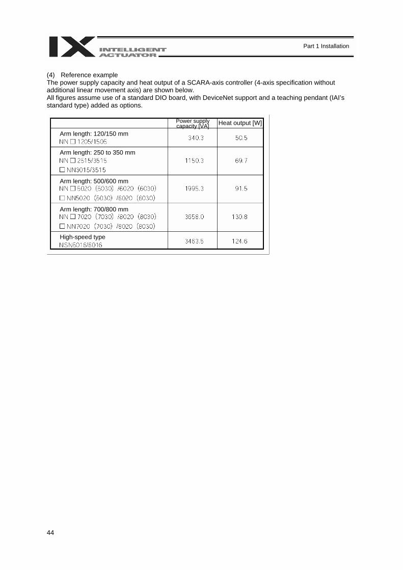
44
Part 1 Installation
(4) Reference example The power supply capacity and heat output of a SCARA-axis controller (4-axis specification without additional linear movement axis) are shown below. All figures assume use of a standard DIO board, with DeviceNet support and a teaching pendant (IAI’s standard type) added as options.
Arm length: 120/150 mm
Arm length: 250 to 350 mm
Arm length: 500/600 mm
Arm length: 700/800 mm
High-speed type
Power supply capacity [VA] Heat output [W]
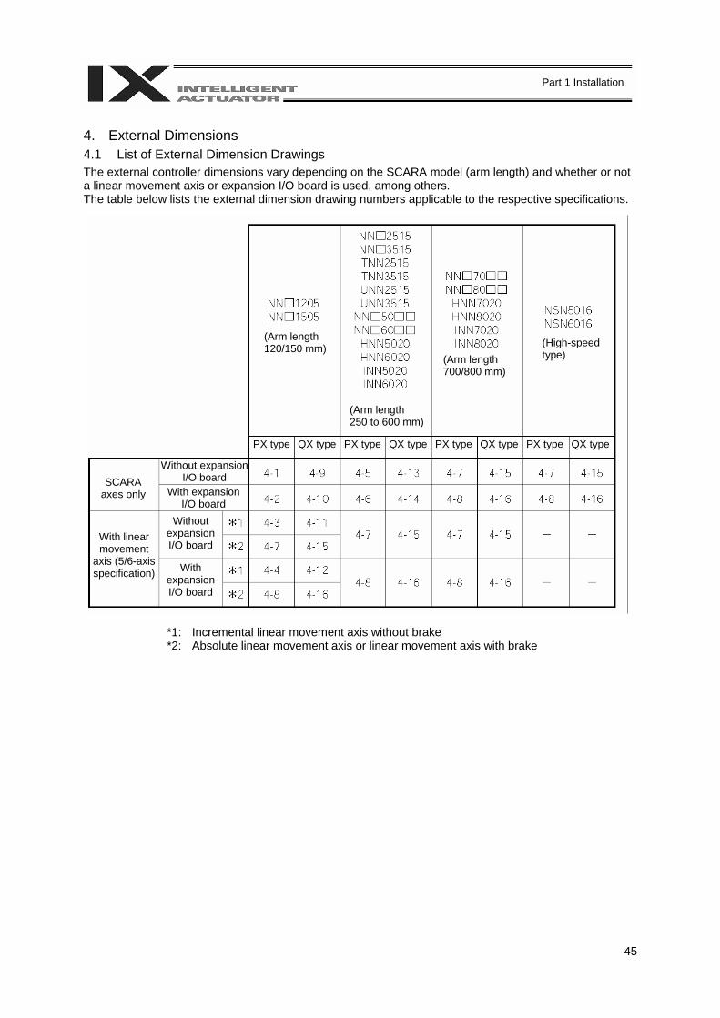
45
Part 1 Installation
4. External Dimensions 4.1 List of External Dimension Drawings The external controller dimensions vary depending on the SCARA model (arm length) and whether or not a linear movement axis or expansion I/O board is used, among others. The table below lists the external dimension drawing numbers applicable to the respective specifications.
*1: Incremental linear movement axis without brake *2: Absolute linear movement axis or linear movement axis with brake
(Arm length 120/150 mm)
(Arm length 250 to 600 mm)
(Arm length 700/800 mm)
(High-speed type)
PX type QX type PX type QX type PX type QX type PX type QX type
SCARA axes only
With linear movement
axis (5/6-axis specification)
Without expansion I/O board
With expansion I/O board
Without expansion I/O board
With expansion I/O board
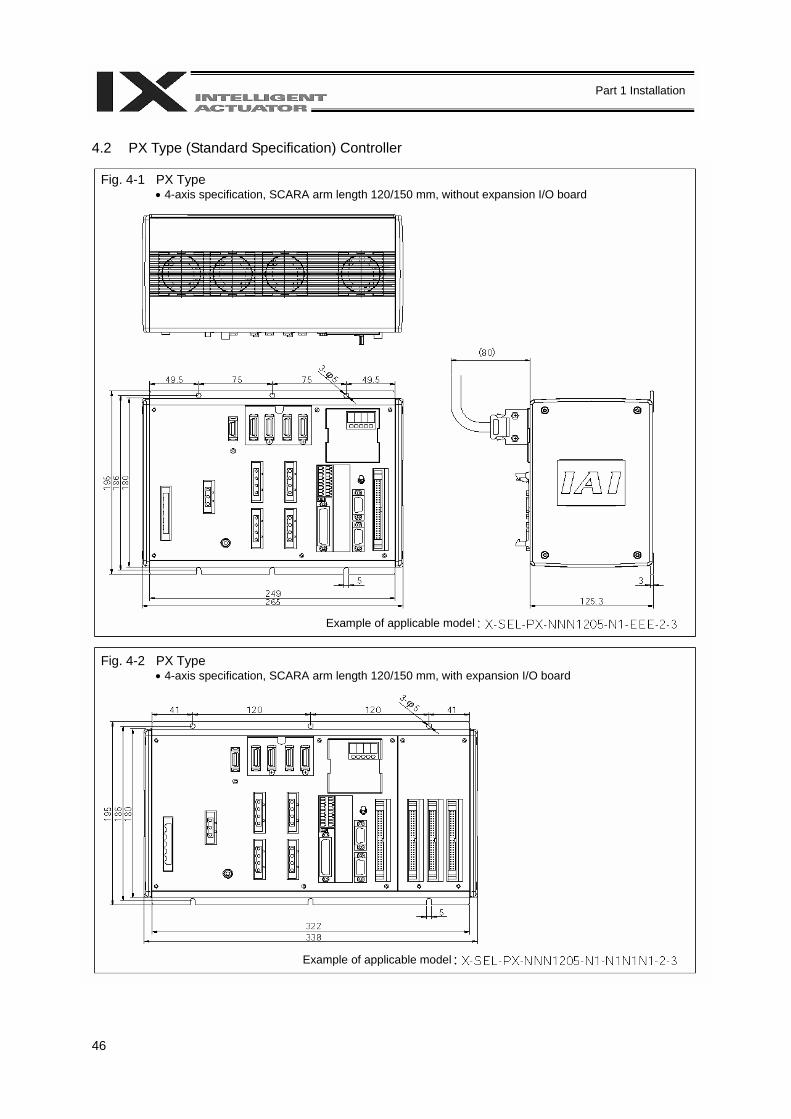
46
Part 1 Installation
4.2 PX Type (Standard Specification) Controller
Fig. 4-1 PX Type • 4-axis specification, SCARA arm length 120/150 mm, without expansion I/O board
Example of applicable model
Fig. 4-2 PX Type • 4-axis specification, SCARA arm length 120/150 mm, with expansion I/O board
Example of applicable model

47
Part 1 Installation
Fig. 4-3 PX Type • 5/6-axis specification, SCARA arm length 120/150 mm, without expansion I/O board,
with incremental linear movement axis without brake
Fig. 4-4 PX Type • 5/6-axis specification, SCARA arm length 120/150 mm, with expansion I/O board,
with incremental linear movement axis without brake
Example of applicable model
Example of applicable model
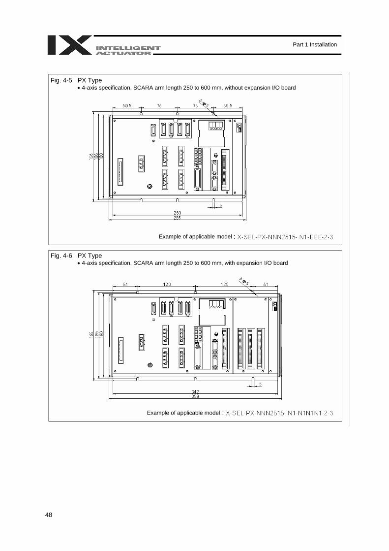
48
Part 1 Installation
Fig. 4-5 PX Type • 4-axis specification, SCARA arm length 250 to 600 mm, without expansion I/O board
Fig. 4-6 PX Type • 4-axis specification, SCARA arm length 250 to 600 mm, with expansion I/O board
Example of applicable model
Example of applicable model
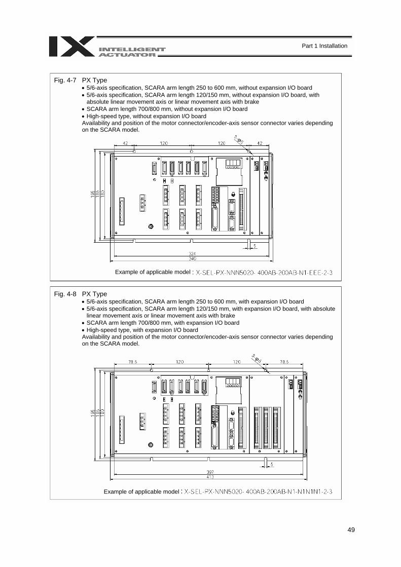
49
Part 1 Installation
Fig. 4-7 PX Type • 5/6-axis specification, SCARA arm length 250 to 600 mm, without expansion I/O board • 5/6-axis specification, SCARA arm length 120/150 mm, without expansion I/O board, with
absolute linear movement axis or linear movement axis with brake • SCARA arm length 700/800 mm, without expansion I/O board • High-speed type, without expansion I/O board Availability and position of the motor connector/encoder-axis sensor connector varies depending on the SCARA model.
Fig. 4-8 PX Type • 5/6-axis specification, SCARA arm length 250 to 600 mm, with expansion I/O board • 5/6-axis specification, SCARA arm length 120/150 mm, with expansion I/O board, with absolute
linear movement axis or linear movement axis with brake • SCARA arm length 700/800 mm, with expansion I/O board • High-speed type, with expansion I/O board Availability and position of the motor connector/encoder-axis sensor connector varies depending on the SCARA model.
Example of applicable model
Example of applicable model
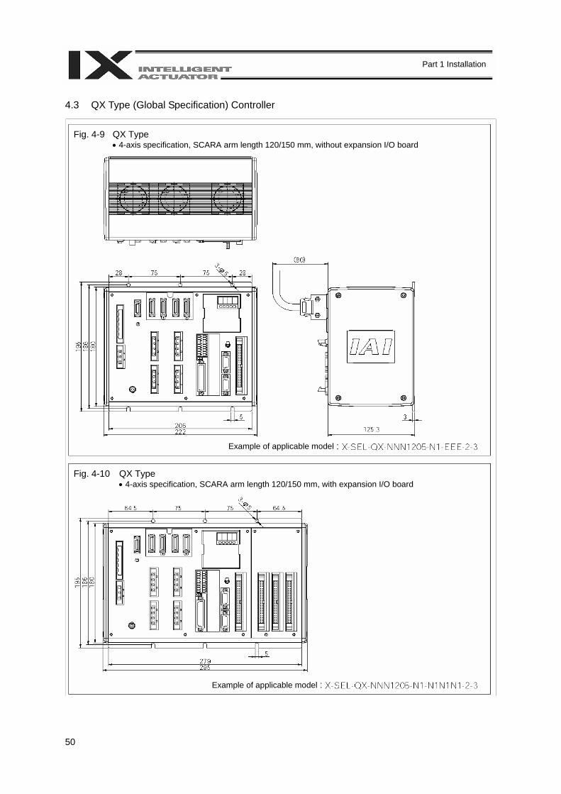
50
Part 1 Installation
4.3 QX Type (Global Specification) Controller
Example of applicable model
Example of applicable model
Fig. 4-9 QX Type • 4-axis specification, SCARA arm length 120/150 mm, without expansion I/O board
Fig. 4-10 QX Type • 4-axis specification, SCARA arm length 120/150 mm, with expansion I/O board
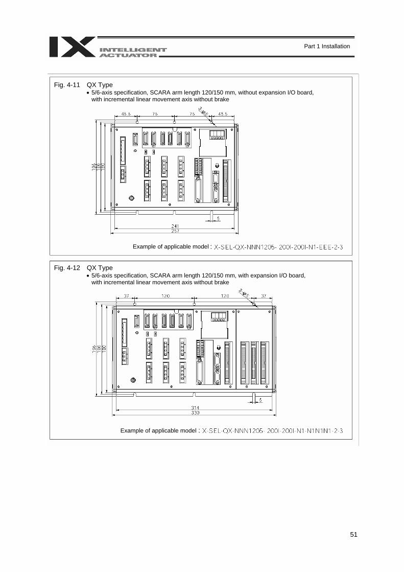
51
Part 1 Installation
Example of applicable model
Example of applicable model
Fig. 4-11 QX Type • 5/6-axis specification, SCARA arm length 120/150 mm, without expansion I/O board,
with incremental linear movement axis without brake
Fig. 4-12 QX Type • 5/6-axis specification, SCARA arm length 120/150 mm, with expansion I/O board,
with incremental linear movement axis without brake
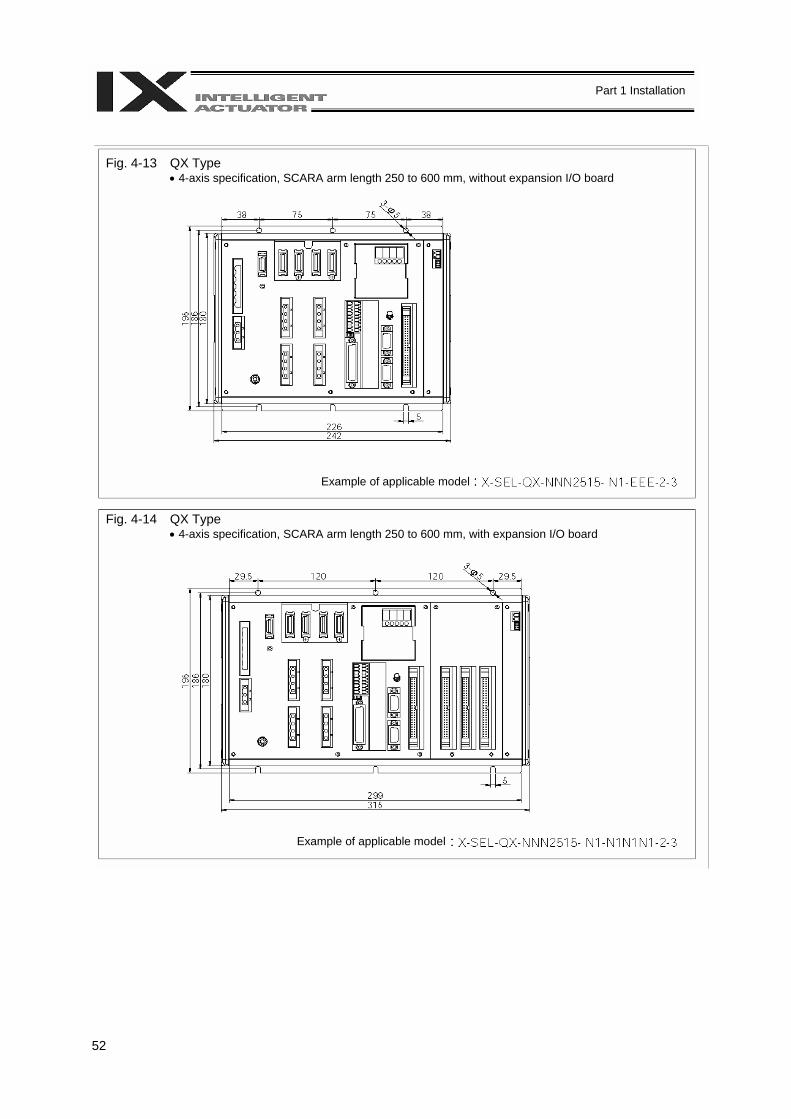
52
Part 1 Installation
Example of applicable model
Example of applicable model
Fig. 4-13 QX Type • 4-axis specification, SCARA arm length 250 to 600 mm, without expansion I/O board
Fig. 4-14 QX Type • 4-axis specification, SCARA arm length 250 to 600 mm, with expansion I/O board
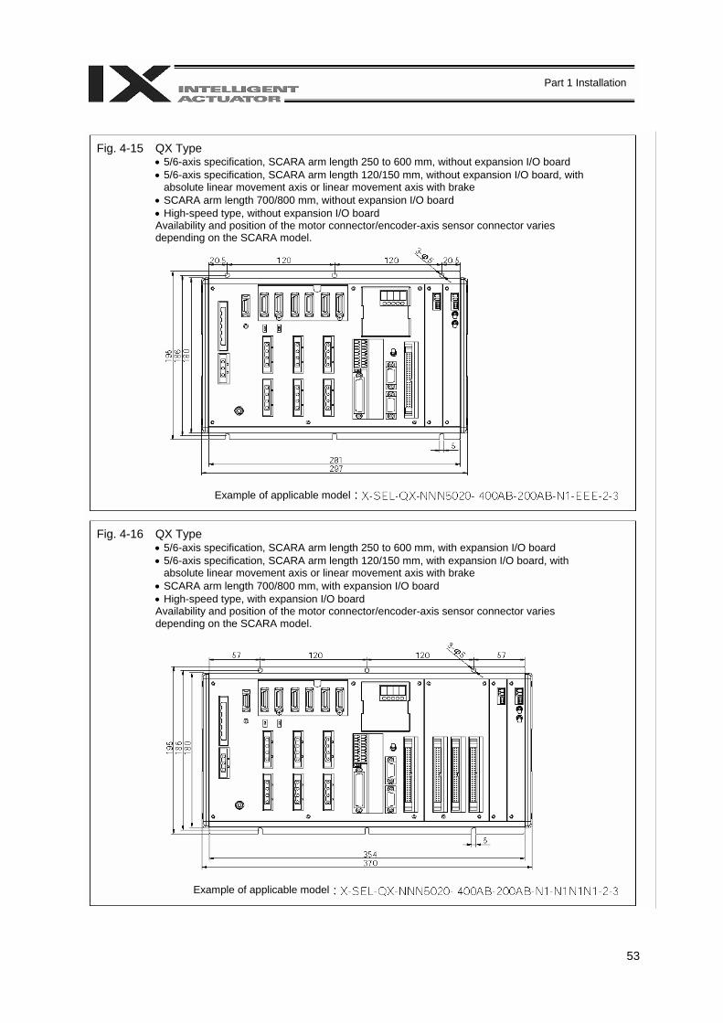
53
Part 1 Installation
Example of applicable model
Example of applicable model
Fig. 4-15 QX Type • 5/6-axis specification, SCARA arm length 250 to 600 mm, without expansion I/O board • 5/6-axis specification, SCARA arm length 120/150 mm, without expansion I/O board, with
absolute linear movement axis or linear movement axis with brake • SCARA arm length 700/800 mm, without expansion I/O board • High-speed type, without expansion I/O board Availability and position of the motor connector/encoder-axis sensor connector varies depending on the SCARA model.
Fig. 4-16 QX Type • 5/6-axis specification, SCARA arm length 250 to 600 mm, with expansion I/O board • 5/6-axis specification, SCARA arm length 120/150 mm, with expansion I/O board, with
absolute linear movement axis or linear movement axis with brake • SCARA arm length 700/800 mm, with expansion I/O board • High-speed type, with expansion I/O board Availability and position of the motor connector/encoder-axis sensor connector varies depending on the SCARA model.

54
Part 1 Installation
Chapter 6 Safety Circuit The circuit configuration for embodying safety actions such as emergency stop is different between the standard specification and global specification of the X-SEL controller. The standard controller has a built-in drive source cutoff circuit conforming to safety category B. The global controller has no built-in drive source cutoff circuit so that the user can configure an external safety circuit appropriate for their equipment configuration. 1. Items to Notes The following explains the items to note regarding the safety circuit, which apply to both the standard specification and global specification. 1. Overview of emergency stop action
The emergency stop control line (drive source cutoff control line) consists entirely of wires. When an emergency stop operation is performed, the controller will execute a stop action of category 1. Specifically, it will stop the actuator at the deceleration for emergency stop as specified by a parameter, and turn off the servo. At this time, the drive source will also be cut off inside the standard controller. With the global controller, the drive source must be cut off externally to the controller. As for recovery from an emergency stop state (including recovery of the drive source), an automatic reset using the emergency stop switch or a method requiring both an emergency stop switch action and an external input signal can be selected by a parameter (I/O parameter No. 44). During an emergency stop, the status can be output to an external device (set by I/O parameter No. 48).
2. Overview of enabling action
Enabling operation (via the safety gate or the deadman switch on the teaching pendant) implements an action similar to the emergency stop action, except that an emergency stop status is not output.
3. Controller operation modes and safety switches on the teaching pendant
The deadman switch on the teaching pendant is enabled only when the controller is in the MANU mode. The emergency stop switch on the teaching pendant is always enabled as long as the teaching pendant is connected to the controller.
4. Connecting a teaching pendant while the controller is operating in the AUTO mode
Connecting a teaching pendant to the controller or removing the connected teaching pendant while the controller is operating in the AUTO mode may trigger an emergency stop. Do not connect/remove a teaching pendant while the controller is operating in the AUTO mode.
5. Applying voltage to the system I/O
The safety circuit of the X-SEL controller is designed to operate with 24 VDC. Therefore, never apply 100 or 200 VAC to the system I/O. Doing so may damage the internal circuitry of the controller.
The following pages explain the safety circuit of each controller specification in details.
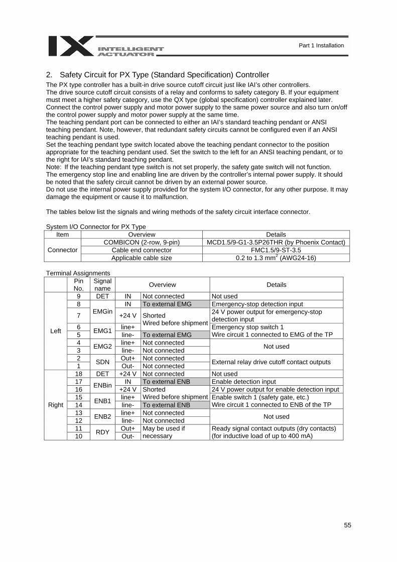
55
Part 1 Installation
2. Safety Circuit for PX Type (Standard Specification) Controller The PX type controller has a built-in drive source cutoff circuit just like IAI’s other controllers. The drive source cutoff circuit consists of a relay and conforms to safety category B. If your equipment must meet a higher safety category, use the QX type (global specification) controller explained later. Connect the control power supply and motor power supply to the same power source and also turn on/off the control power supply and motor power supply at the same time. The teaching pendant port can be connected to either an IAI’s standard teaching pendant or ANSI teaching pendant. Note, however, that redundant safety circuits cannot be configured even if an ANSI teaching pendant is used. Set the teaching pendant type switch located above the teaching pendant connector to the position appropriate for the teaching pendant used. Set the switch to the left for an ANSI teaching pendant, or to the right for IAI’s standard teaching pendant. Note: If the teaching pendant type switch is not set properly, the safety gate switch will not function. The emergency stop line and enabling line are driven by the controller’s internal power supply. It should be noted that the safety circuit cannot be driven by an external power source. Do not use the internal power supply provided for the system I/O connector, for any other purpose. It may damage the equipment or cause it to malfunction. The tables below list the signals and wiring methods of the safety circuit interface connector. System I/O Connector for PX Type
Item Overview Details COMBICON (2-row, 9-pin) MCD1.5/9-G1-3.5P26THR (by Phoenix Contact)
Cable end connector FMC1.5/9-ST-3.5 Connector Applicable cable size 0.2 to 1.3 mm2 (AWG24-16)
Terminal Assignments
Pin No.
Signal name Overview Details
9 DET IN Not connected Not used 8 IN To external EMG Emergency-stop detection input
7 EMGin +24 V 24 V power output for emergency-stop detection input
6 line+
Shorted Wired before shipment
5 EMG1 line- To external EMG Emergency stop switch 1 Wire circuit 1 connected to EMG of the TP
4 line+ Not connected 3 EMG2 line- Not connected Not used
2 Out+ Not connected
Left
1 SDN Out- Not connected External relay drive cutoff contact outputs
18 DET +24 V Not connected Not used 17 IN To external ENB Enable detection input 16 ENBin +24 V 24 V power output for enable detection input 15 line+
Shorted Wired before shipment
14 ENB1 line- To external ENB Enable switch 1 (safety gate, etc.) Wire circuit 1 connected to ENB of the TP
13 line+ Not connected 12 ENB2 line- Not connected Not used
11 Out+
Right
10 RDY Out- May be used if necessary
Ready signal contact outputs (dry contacts) (for inductive load of up to 400 mA)
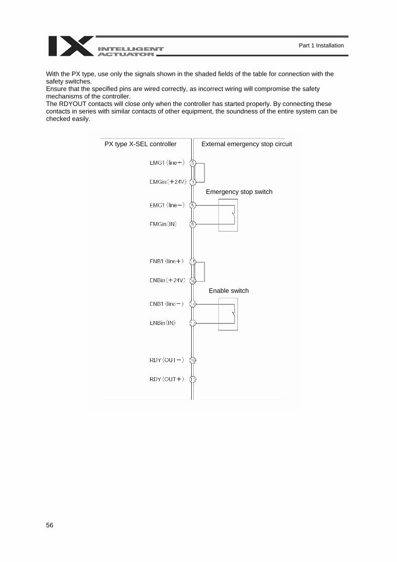
56
Part 1 Installation
With the PX type, use only the signals shown in the shaded fields of the table for connection with the safety switches. Ensure that the specified pins are wired correctly, as incorrect wiring will compromise the safety mechanisms of the controller. The RDYOUT contacts will close only when the controller has started properly. By connecting these contacts in series with similar contacts of other equipment, the soundness of the entire system can be checked easily.
PX type X-SEL controller External emergency stop circuit
Emergency stop switch
Enable switch

57
Part 1 Installation
3. Safety Circuit for QX Type (Global Specification) Controller The global controller has no internal drive source cutoff circuit so that the user can configure a desired drive source cutoff circuit externally to the controller to conform to the required safety category. The safety circuit consists of two circuits: the emergency stop (EMG) circuit and enable (ENB) circuit. Each circuit adopts a redundant design, so a safety circuit conforming to a higher safety category of up to level 4 can be configured using an external drive source cutoff circuit. Since this controller has no built-in drive source cutoff circuit, be sure to install a drive source cutoff circuit in the motor power circuit. It is recommended that the control power supply be wired from the same power source as the motor power supply at a point before the drive-source cutoff part is connected. Please note that IAI is not liable for any losses arising from a malfunction of the safety circuit configured by the user. The teaching pendant port can be connected to either IAI’s standard teaching pendant or ANSI teaching pendant. Note, however, that the ANSI safety standards can be met only when an ANSI teaching pendant is used. If IAI’s standard teaching pendant is used, redundant safety circuits cannot be configured. Set the teaching pendant type switch located above the teaching pendant connector to the position appropriate for the teaching pendant used. Set the switch to the left for an ANSI teaching pendant, or to the right for IAI’s standard teaching pendant. Note: If the teaching pendant type switch is not set properly, the safety gate switch will not function. The redundant emergency stop lines and enabling lines are designed with the assumption that they will be driven by a power source external to the controller. Note, however, that the inputs to the contacts that provide for emergency stop action and enabling action operate on the internal power supply. Do not use the internal power supply provided for the system I/O connector for any other purpose. It may damage the equipment or cause it to malfunction. The tables below list the signals and wiring methods of the safety circuit interface connector. The connector pin assignments and internal circuit components are the same as those of the standard specification. System I/O Connector for QX type
Item Overview Details COMBICON (2-row, 9-pin) MCD1.5/9-G1-3.5P26THR (by Phoenix Contact)
Cable end connector FMC1.5/9-ST-3.5 Connector
Applicable cable size 0.2 ~ 1.3 mm2 (AWG24-16)
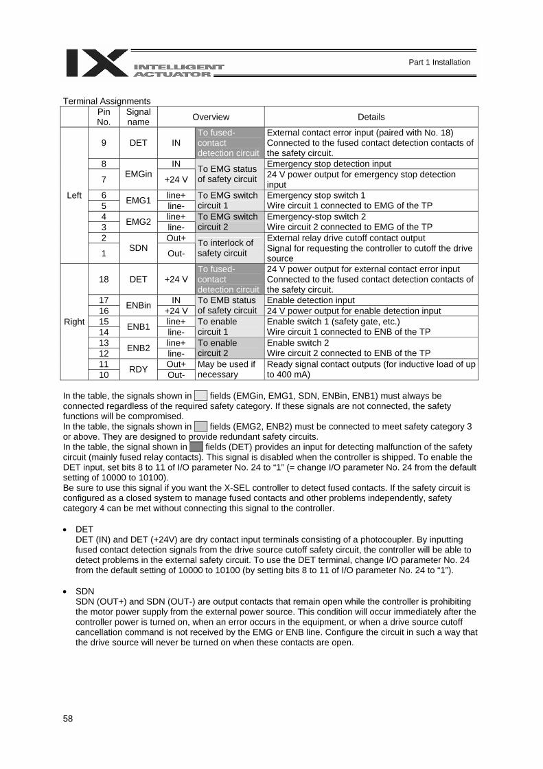
58
Part 1 Installation
Terminal Assignments
Pin No.
Signal name Overview Details
9 DET IN To fused-contact detection circuit
External contact error input (paired with No. 18) Connected to the fused contact detection contacts of the safety circuit.
8 IN Emergency stop detection input
7 EMGin +24 V To EMG status of safety circuit 24 V power output for emergency stop detection
input 6 line+ 5 EMG1 line-
To EMG switch circuit 1
Emergency stop switch 1 Wire circuit 1 connected to EMG of the TP
4 line+ 3 EMG2 line-
To EMG switch circuit 2
Emergency-stop switch 2 Wire circuit 2 connected to EMG of the TP
2 Out+
Left
1 SDN Out- To interlock of safety circuit
External relay drive cutoff contact output Signal for requesting the controller to cutoff the drive source
18 DET +24 V To fused-contact detection circuit
24 V power output for external contact error input Connected to the fused contact detection contacts of the safety circuit.
17 IN Enable detection input 16 ENBin +24 V
To EMB status of safety circuit 24 V power output for enable detection input
15 line+ 14 ENB1 line-
To enable circuit 1
Enable switch 1 (safety gate, etc.) Wire circuit 1 connected to ENB of the TP
13 line+ 12 ENB2 line-
To enable circuit 2
Enable switch 2 Wire circuit 2 connected to ENB of the TP
11 Out+
Right
10 RDY Out- May be used if necessary
Ready signal contact outputs (for inductive load of up to 400 mA)
In the table, the signals shown in fields (EMGin, EMG1, SDN, ENBin, ENB1) must always be connected regardless of the required safety category. If these signals are not connected, the safety functions will be compromised. In the table, the signals shown in fields (EMG2, ENB2) must be connected to meet safety category 3 or above. They are designed to provide redundant safety circuits. In the table, the signal shown in fields (DET) provides an input for detecting malfunction of the safety circuit (mainly fused relay contacts). This signal is disabled when the controller is shipped. To enable the DET input, set bits 8 to 11 of I/O parameter No. 24 to “1” (= change I/O parameter No. 24 from the default setting of 10000 to 10100). Be sure to use this signal if you want the X-SEL controller to detect fused contacts. If the safety circuit is configured as a closed system to manage fused contacts and other problems independently, safety category 4 can be met without connecting this signal to the controller. • DET
DET (IN) and DET (+24V) are dry contact input terminals consisting of a photocoupler. By inputting fused contact detection signals from the drive source cutoff safety circuit, the controller will be able to detect problems in the external safety circuit. To use the DET terminal, change I/O parameter No. 24 from the default setting of 10000 to 10100 (by setting bits 8 to 11 of I/O parameter No. 24 to “1”).
• SDN
SDN (OUT+) and SDN (OUT-) are output contacts that remain open while the controller is prohibiting the motor power supply from the external power source. This condition will occur immediately after the controller power is turned on, when an error occurs in the equipment, or when a drive source cutoff cancellation command is not received by the EMG or ENB line. Configure the circuit in such a way that the drive source will never be turned on when these contacts are open.

59
Part 1 Installation
• EMG1/EMG2, ENB1/ENB2
EMG1 (line+)/(line-) and EMG2 (line+)/(line-) are redundant emergency stop control lines. ENB1 (line+)/(line-) and ENB2 (line+)/(line-) are redundant enabling control lines. Use these lines to cut off the external drive source. Since they are completely dry signal lines, configure a relay circuit using an external power source.
• EMGin, ENBin
EMGin (IN) and EMGin (+24V) are contact inputs that notify the controller of the drive source cutoff input received by the drive source cutoff circuit via an EMG signal. ENBin (IN) and ENBin (+24V) are contact inputs that notify the controller via an ENB signal. These contact signals are used to decelerate the actuator to a stop or turn off the servo. Normally, a safety relay output is connected to each of these inputs.
• RDY
RDY (OUT+) and RDY (OUT-) are output contacts that will close only when the controller has started properly. By connecting these contacts in series with similar contacts of other equipment, the soundness of the entire system can be checked easily.
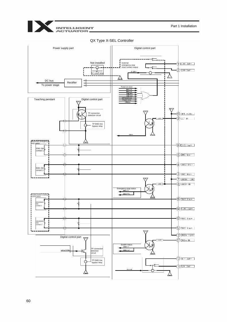
60
Part 1 Installation
QX Type X-SEL Controller
Power supply part Digital control part
Not installed
AC cutoff relay
Rectifier DC bus To power stage
External emergency-stop reset contact output
Teaching pendant Digital control part
TP connection detection circuit
TP EMG line bypass relay
Power-on reset
MPSDWN bit Power error
Mushroom emergency-stop switch
EMG SW contact 1
EMG SW contact 2
Double-position enabling-control switch
DEADMAN SW contact 1
DEADMAN SW contact 2
Digital control part
TP connection detection circuit
TP EMG line bypass relay
Emergency-stop status
Enable status

61
Part 1 Installation
External Emergency Stop Circuit
Contactor (NEO SC)Relay
Contactor (NEO SC)
200-VAC, three-phase
Reset switch
External emergency-stop switch
External EMG switch contact 1
External EMG switch contact 2
Safety relay unit (G9SA-301 by Omron)
Safety gate switch
External SGATE contact 1
External SGATE contact 2
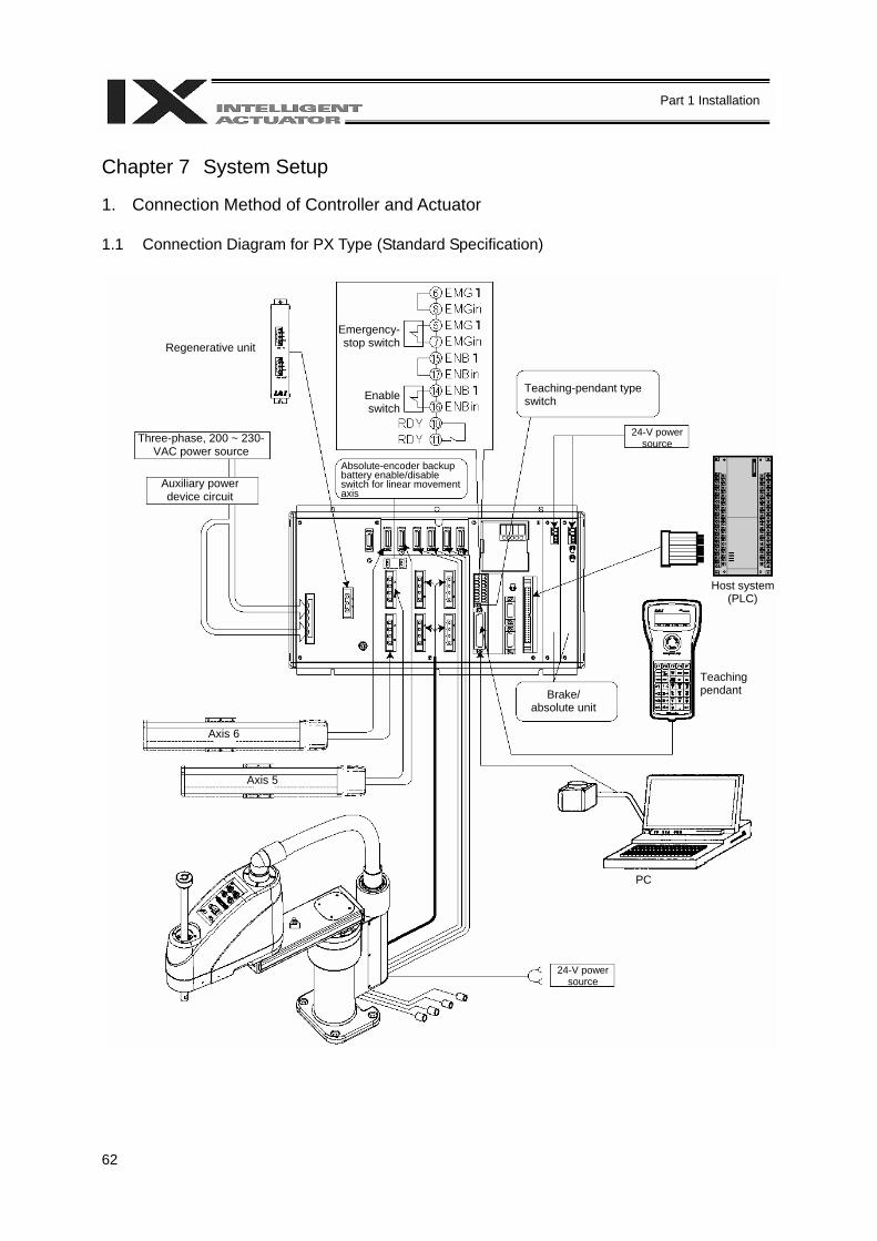
62
Part 1 Installation
Chapter 7 System Setup 1. Connection Method of Controller and Actuator 1.1 Connection Diagram for PX Type (Standard Specification)
Three-phase, 200 ~ 230-VAC power source
Auxiliary power device circuit
Emergency-stop switch
Enable switch
Teaching-pendant type switch
Axis 5
Regenerative unit
Host system (PLC)
Teaching pendant
PC
Axis 6
Absolute-encoder backup battery enable/disable switch for linear movement axis
24-V power source
Brake/ absolute unit
24-V power source
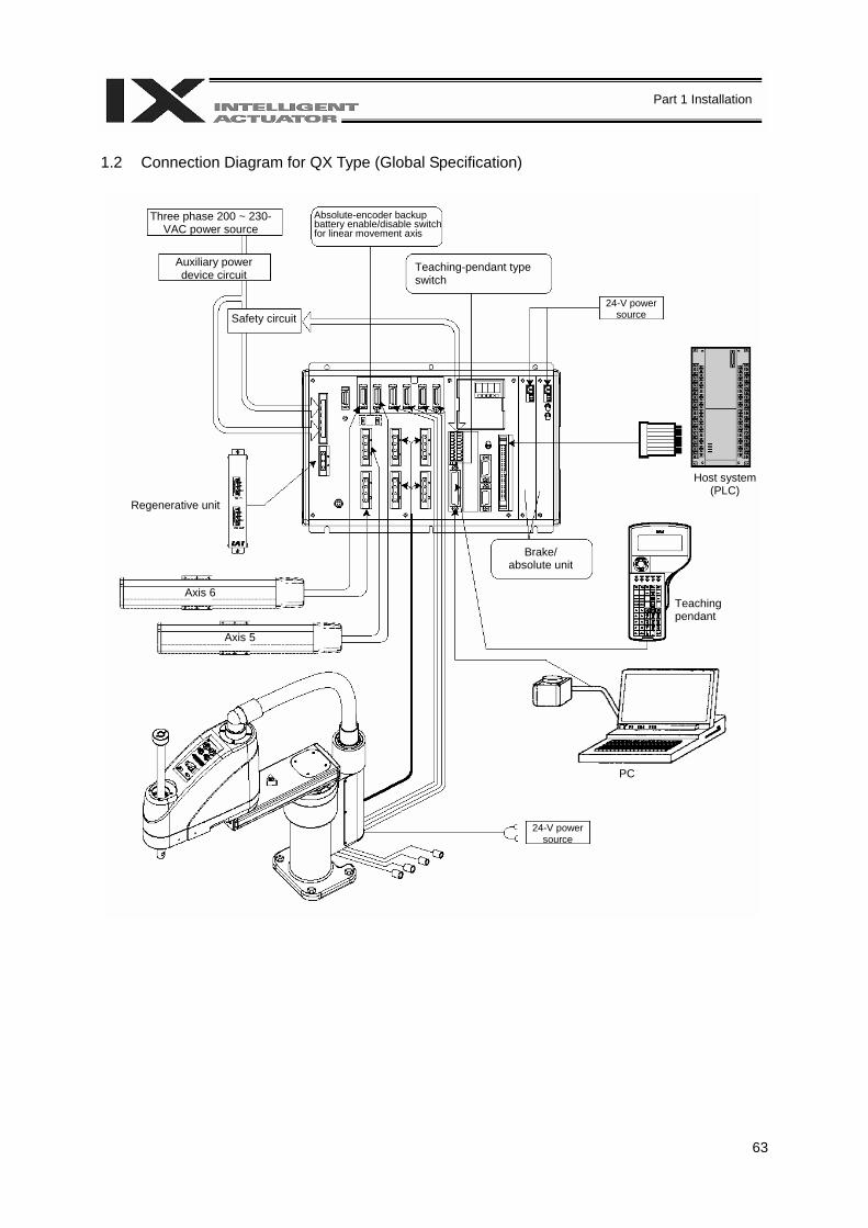
63
Part 1 Installation
1.2 Connection Diagram for QX Type (Global Specification)
Three phase 200 ~ 230-VAC power source
Auxiliary power device circuit
Teaching-pendant type switch
Safety circuit
Axis 5
Regenerative unit
Host system (PLC)
Teaching pendant
PC
Axis 6
Absolute-encoder backup battery enable/disable switch for linear movement axis
24-V power source
Brake/ absolute unit
24-V power source
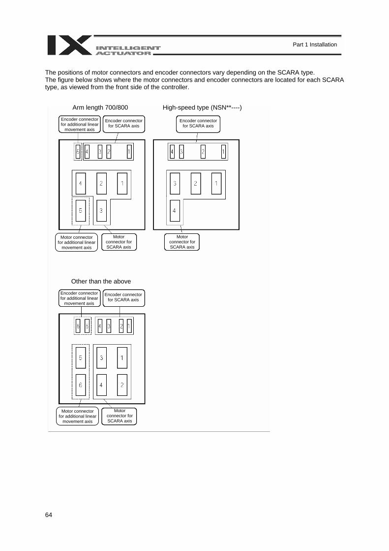
64
Part 1 Installation
The positions of motor connectors and encoder connectors vary depending on the SCARA type. The figure below shows where the motor connectors and encoder connectors are located for each SCARA type, as viewed from the front side of the controller.
Arm length 700/800 High-speed type (NSN**----)
Other than the above
Encoder connector for additional linear
movement axis Encoder connector
for SCARA axis Encoder connector
for SCARA axis
Encoder connector for additional linear
movement axis Encoder connector
for SCARA axis
Motor connector for SCARA axis
Motor connector for additional linear
movement axis
Motor connector for SCARA axis
Motor connector for SCARA axis
Motor connector for additional linear
movement axis
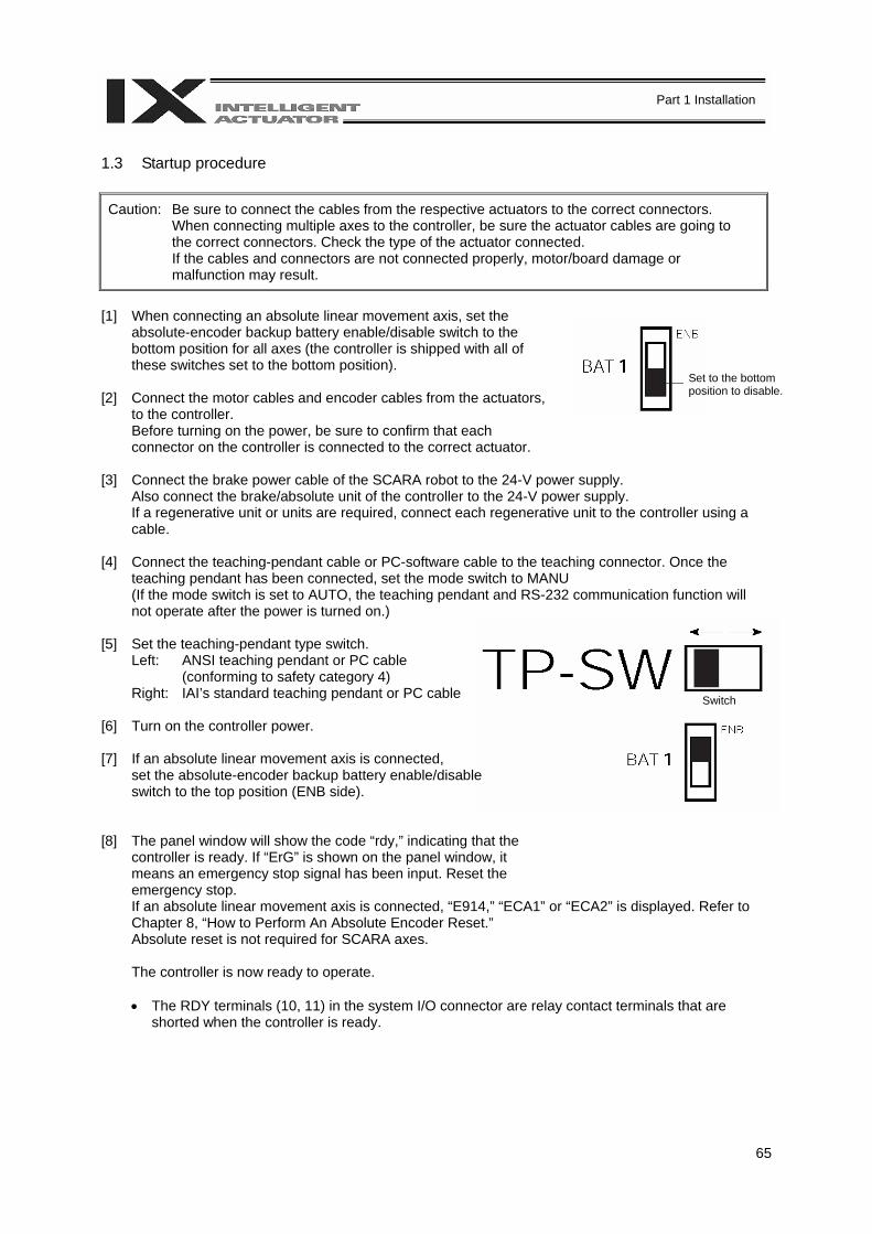
65
Part 1 Installation
Switch
1.3 Startup procedure
Caution: Be sure to connect the cables from the respective actuators to the correct connectors. When connecting multiple axes to the controller, be sure the actuator cables are going to the correct connectors. Check the type of the actuator connected. If the cables and connectors are not connected properly, motor/board damage or malfunction may result.
[1] When connecting an absolute linear movement axis, set the
absolute-encoder backup battery enable/disable switch to the bottom position for all axes (the controller is shipped with all of these switches set to the bottom position).
[2] Connect the motor cables and encoder cables from the actuators,
to the controller. Before turning on the power, be sure to confirm that each connector on the controller is connected to the correct actuator.
[3] Connect the brake power cable of the SCARA robot to the 24-V power supply.
Also connect the brake/absolute unit of the controller to the 24-V power supply. If a regenerative unit or units are required, connect each regenerative unit to the controller using a cable.
[4] Connect the teaching-pendant cable or PC-software cable to the teaching connector. Once the
teaching pendant has been connected, set the mode switch to MANU (If the mode switch is set to AUTO, the teaching pendant and RS-232 communication function will not operate after the power is turned on.)
[5] Set the teaching-pendant type switch.
Left: ANSI teaching pendant or PC cable (conforming to safety category 4)
Right: IAI’s standard teaching pendant or PC cable
[6] Turn on the controller power. [7] If an absolute linear movement axis is connected,
set the absolute-encoder backup battery enable/disable switch to the top position (ENB side).
[8] The panel window will show the code “rdy,” indicating that the
controller is ready. If “ErG” is shown on the panel window, it means an emergency stop signal has been input. Reset the emergency stop. If an absolute linear movement axis is connected, “E914,” “ECA1” or “ECA2” is displayed. Refer to Chapter 8, “How to Perform An Absolute Encoder Reset.” Absolute reset is not required for SCARA axes.
The controller is now ready to operate.
• The RDY terminals (10, 11) in the system I/O connector are relay contact terminals that are
shorted when the controller is ready.
Set to the bottom position to disable.
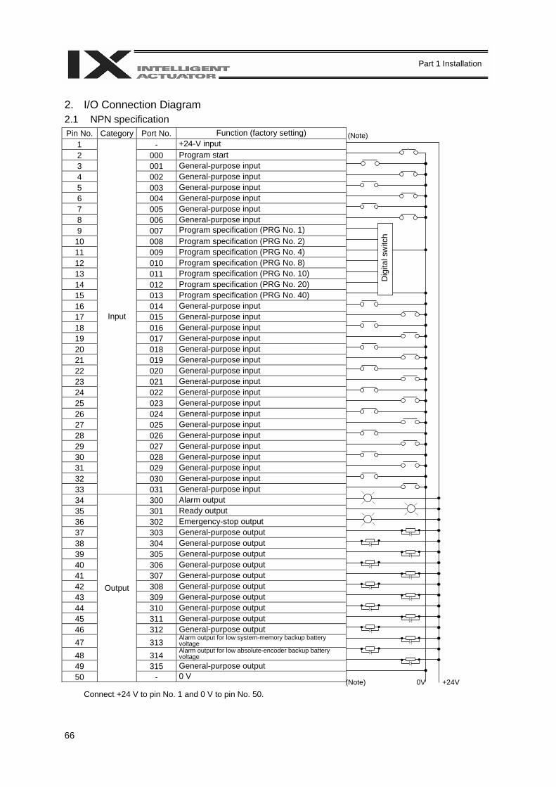
66
Part 1 Installation
2. I/O Connection Diagram 2.1 NPN specification Pin No. Category Port No. Function (factory setting)
1 - +24-V input 2 000 Program start 3 001 General-purpose input 4 002 General-purpose input 5 003 General-purpose input 6 004 General-purpose input 7 005 General-purpose input 8 006 General-purpose input 9 007 Program specification (PRG No. 1) 10 008 Program specification (PRG No. 2) 11 009 Program specification (PRG No. 4) 12 010 Program specification (PRG No. 8) 13 011 Program specification (PRG No. 10) 14 012 Program specification (PRG No. 20) 15 013 Program specification (PRG No. 40) 16 014 General-purpose input 17 015 General-purpose input 18 016 General-purpose input 19 017 General-purpose input 20 018 General-purpose input 21 019 General-purpose input 22 020 General-purpose input 23 021 General-purpose input 24 022 General-purpose input 25 023 General-purpose input 26 024 General-purpose input 27 025 General-purpose input 28 026 General-purpose input 29 027 General-purpose input 30 028 General-purpose input 31 029 General-purpose input 32 030 General-purpose input 33
Input
031 General-purpose input 34 300 Alarm output 35 301 Ready output 36 302 Emergency-stop output 37 303 General-purpose output 38 304 General-purpose output 39 305 General-purpose output 40 306 General-purpose output 41 307 General-purpose output 42 308 General-purpose output 43 309 General-purpose output 44 310 General-purpose output 45 311 General-purpose output 46 312 General-purpose output 47 313
Alarm output for low system-memory backup battery voltage
48 314 Alarm output for low absolute-encoder backup battery voltage
49 315 General-purpose output 50
Output
- 0 V
Connect +24 V to pin No. 1 and 0 V to pin No. 50.
(Note)
Dig
ital s
witc
h
(Note) 0V +24V
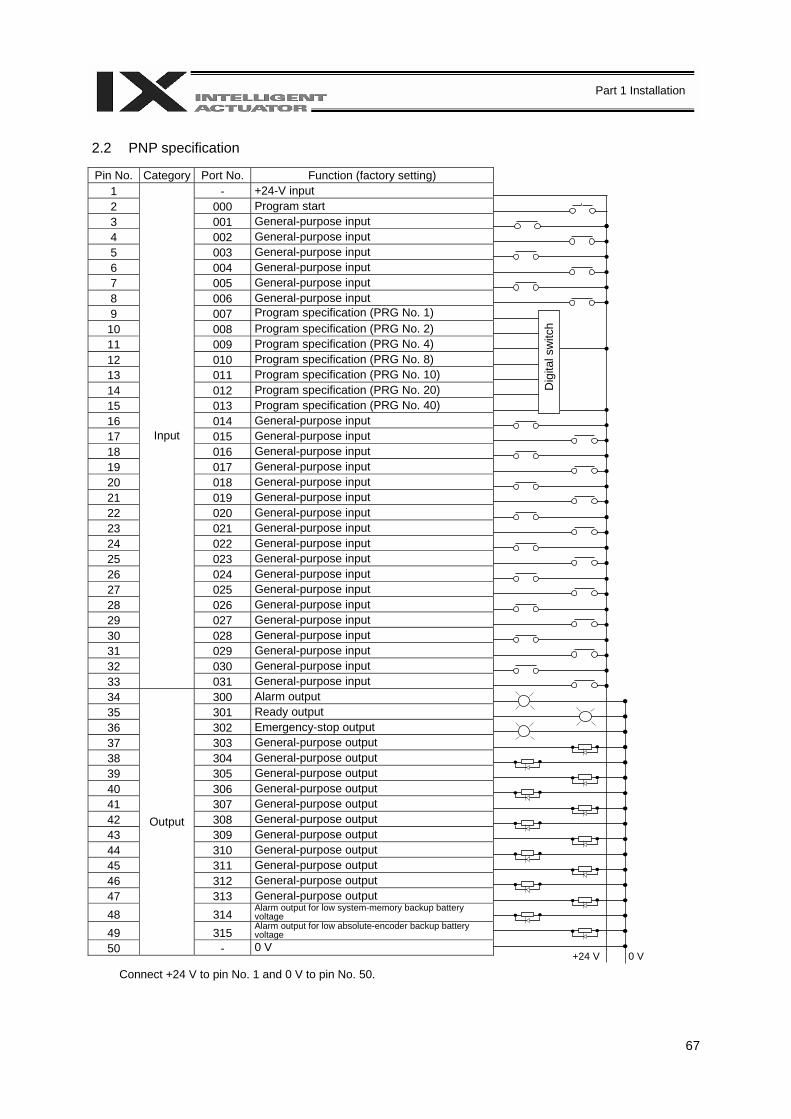
67
Part 1 Installation
2.2 PNP specification
Pin No. Category Port No. Function (factory setting) 1 - +24-V input 2 000 Program start 3 001 General-purpose input 4 002 General-purpose input 5 003 General-purpose input 6 004 General-purpose input 7 005 General-purpose input 8 006 General-purpose input 9 007 Program specification (PRG No. 1) 10 008 Program specification (PRG No. 2) 11 009 Program specification (PRG No. 4) 12 010 Program specification (PRG No. 8) 13 011 Program specification (PRG No. 10) 14 012 Program specification (PRG No. 20) 15 013 Program specification (PRG No. 40) 16 014 General-purpose input 17 015 General-purpose input 18 016 General-purpose input 19 017 General-purpose input 20 018 General-purpose input 21 019 General-purpose input 22 020 General-purpose input 23 021 General-purpose input 24 022 General-purpose input 25 023 General-purpose input 26 024 General-purpose input 27 025 General-purpose input 28 026 General-purpose input 29 027 General-purpose input 30 028 General-purpose input 31 029 General-purpose input 32 030 General-purpose input 33
Input
031 General-purpose input 34 300 Alarm output 35 301 Ready output 36 302 Emergency-stop output 37 303 General-purpose output 38 304 General-purpose output 39 305 General-purpose output 40 306 General-purpose output 41 307 General-purpose output 42 308 General-purpose output 43 309 General-purpose output 44 310 General-purpose output 45 311 General-purpose output 46 312 General-purpose output 47 313 General-purpose output 48 314
Alarm output for low system-memory backup battery voltage
49 315 Alarm output for low absolute-encoder backup battery voltage
50
Output
- 0 V
Connect +24 V to pin No. 1 and 0 V to pin No. 50. 0 V +24 V
Dig
ital s
witc
h

68
Part 1 Installation
2.3 I/O Flat Cable
Flat cable: KFX-50 (S) (Color) (Kaneko Cord)
No. Color No. Color No. Color No. Color No. Color 1 Brown-1 11 Brown-2 21 Brown-3 31 Brown-4 41 Brown-5 2 Red-1 12 Red-2 22 Red-3 32 Red-4 42 Red-5 3 Orange-1 13 Orange-2 23 Orange-3 33 Orange-4 43 Orange-5 4 Yellow-1 14 Yellow-2 24 Yellow-3 34 Yellow-4 44 Yellow-5 5 Green-1 15 Green-2 25 Green-3 35 Green-4 45 Green-5 6 Blue-1 16 Blue-2 26 Blue-3 36 Blue-4 46 Blue-5 7 Purple-1 17 Purple-2 27 Purple-3 37 Purple-4 47 Purple-5 8 Gray-1 18 Gray-2 28 Gray-3 38 Gray-4 48 Gray-5 9 White-1 19 White-2 29 White-3 39 White-4 49 White-5 10 Black-1 20 Black-2 30 Black-3 40 Black-4 50 Black-5
Connector not attached
Socket (with strain relief): XG4M-5030-T (Omron)
Flat cable (50 cores)
2 1
50 49
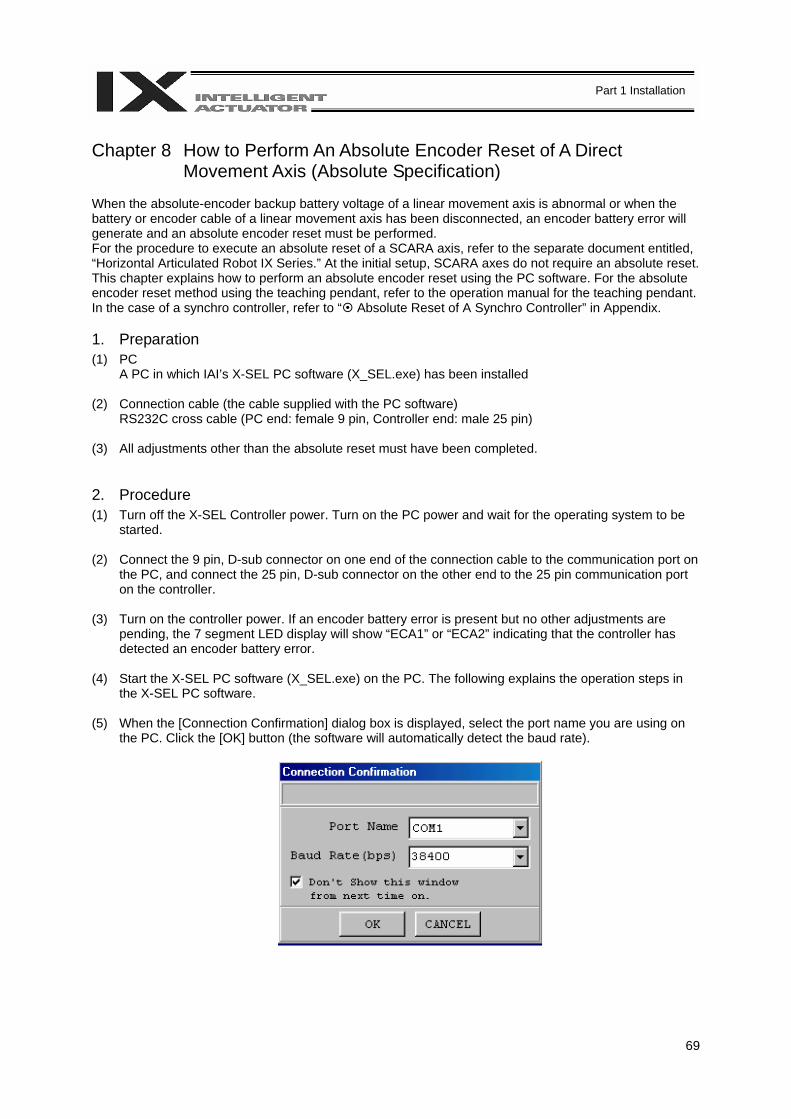
69
Part 1 Installation
Chapter 8 How to Perform An Absolute Encoder Reset of A Direct
Movement Axis (Absolute Specification) When the absolute-encoder backup battery voltage of a linear movement axis is abnormal or when the battery or encoder cable of a linear movement axis has been disconnected, an encoder battery error will generate and an absolute encoder reset must be performed. For the procedure to execute an absolute reset of a SCARA axis, refer to the separate document entitled, “Horizontal Articulated Robot IX Series.” At the initial setup, SCARA axes do not require an absolute reset. This chapter explains how to perform an absolute encoder reset using the PC software. For the absolute encoder reset method using the teaching pendant, refer to the operation manual for the teaching pendant. In the case of a synchro controller, refer to “ Absolute Reset of A Synchro Controller” in Appendix. 1. Preparation (1) PC
A PC in which IAI’s X-SEL PC software (X_SEL.exe) has been installed (2) Connection cable (the cable supplied with the PC software)
RS232C cross cable (PC end: female 9 pin, Controller end: male 25 pin) (3) All adjustments other than the absolute reset must have been completed. 2. Procedure (1) Turn off the X-SEL Controller power. Turn on the PC power and wait for the operating system to be
started. (2) Connect the 9 pin, D-sub connector on one end of the connection cable to the communication port on
the PC, and connect the 25 pin, D-sub connector on the other end to the 25 pin communication port on the controller.
(3) Turn on the controller power. If an encoder battery error is present but no other adjustments are
pending, the 7 segment LED display will show “ECA1” or “ECA2” indicating that the controller has detected an encoder battery error.
(4) Start the X-SEL PC software (X_SEL.exe) on the PC. The following explains the operation steps in
the X-SEL PC software. (5) When the [Connection Confirmation] dialog box is displayed, select the port name you are using on
the PC. Click the [OK] button (the software will automatically detect the baud rate).
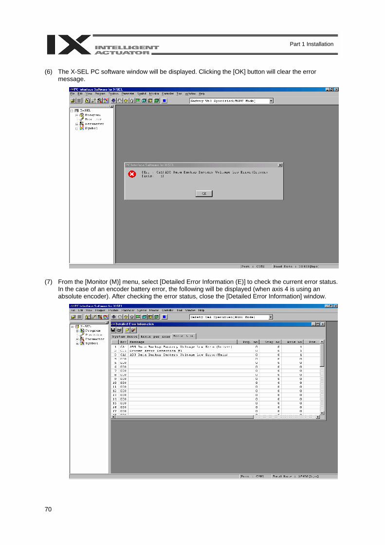
70
Part 1 Installation
(6) The X-SEL PC software window will be displayed. Clicking the [OK] button will clear the error
message. (7) From the [Monitor (M)] menu, select [Detailed Error Information (E)] to check the current error status.
In the case of an encoder battery error, the following will be displayed (when axis 4 is using an absolute encoder). After checking the error status, close the [Detailed Error Information] window.
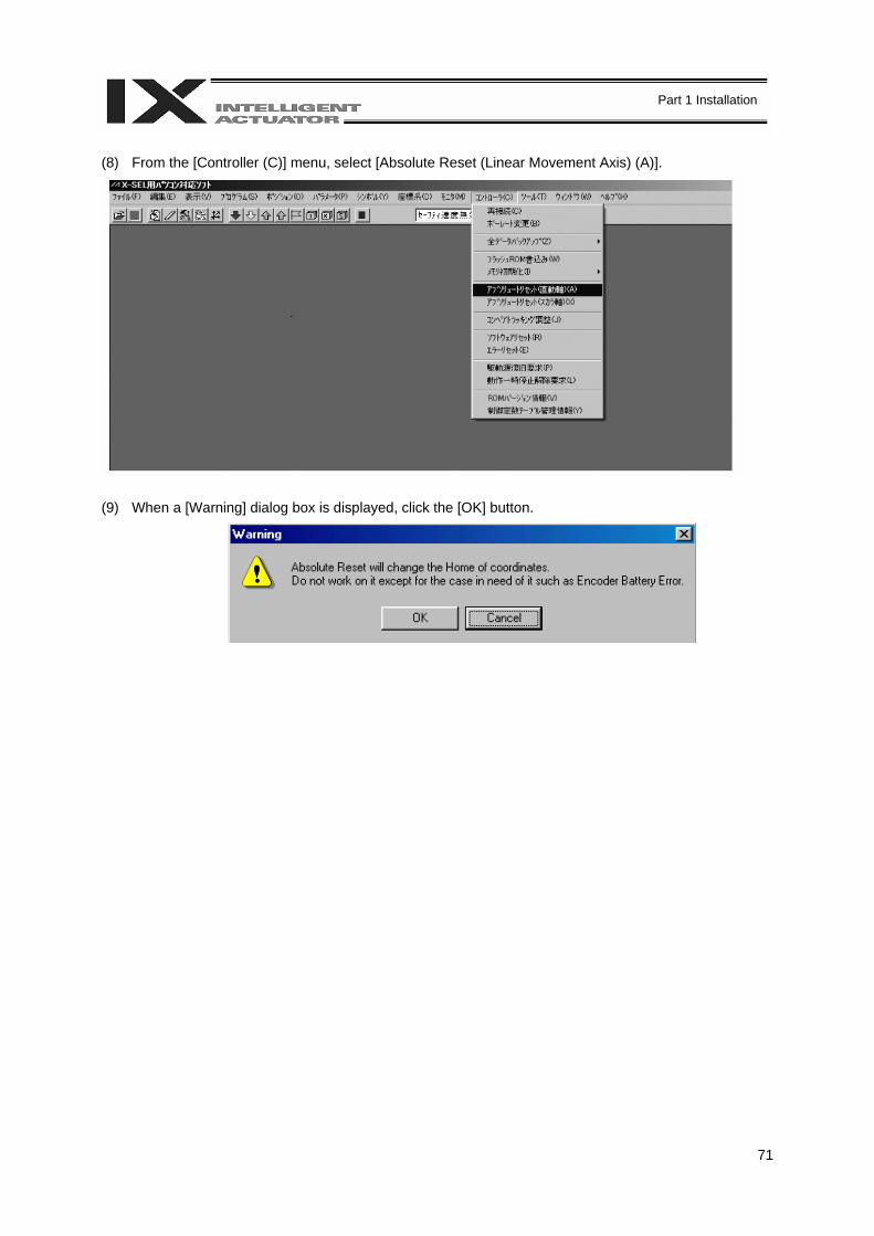
71
Part 1 Installation
(8) From the [Controller (C)] menu, select [Absolute Reset (Linear Movement Axis) (A)]. (9) When a [Warning] dialog box is displayed, click the [OK] button.
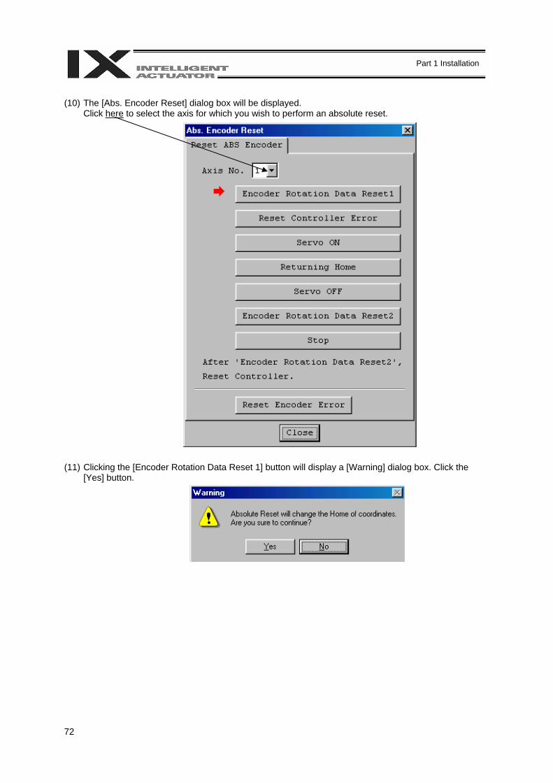
72
Part 1 Installation
(10) The [Abs. Encoder Reset] dialog box will be displayed.
Click here to select the axis for which you wish to perform an absolute reset. (11) Clicking the [Encoder Rotation Data Reset 1] button will display a [Warning] dialog box. Click the
[Yes] button.
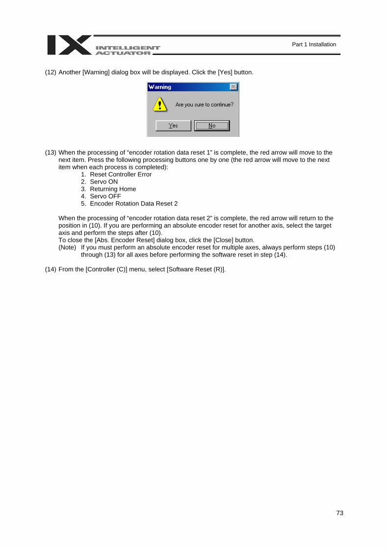
73
Part 1 Installation
(12) Another [Warning] dialog box will be displayed. Click the [Yes] button. (13) When the processing of “encoder rotation data reset 1” is complete, the red arrow will move to the
next item. Press the following processing buttons one by one (the red arrow will move to the next item when each process is completed):
1. Reset Controller Error 2. Servo ON 3. Returning Home 4. Servo OFF 5. Encoder Rotation Data Reset 2
When the processing of “encoder rotation data reset 2” is complete, the red arrow will return to the position in (10). If you are performing an absolute encoder reset for another axis, select the target axis and perform the steps after (10). To close the [Abs. Encoder Reset] dialog box, click the [Close] button. (Note) If you must perform an absolute encoder reset for multiple axes, always perform steps (10)
through (13) for all axes before performing the software reset in step (14). (14) From the [Controller (C)] menu, select [Software Reset (R)].
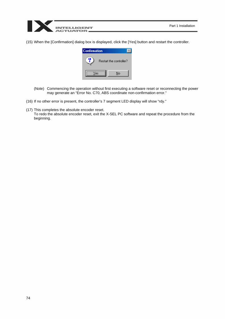
74
Part 1 Installation
(15) When the [Confirmation] dialog box is displayed, click the [Yes] button and restart the controller.
(Note) Commencing the operation without first executing a software reset or reconnecting the power may generate an “Error No. C70, ABS coordinate non-confirmation error.”
(16) If no other error is present, the controller’s 7 segment LED display will show “rdy.” (17) This completes the absolute encoder reset.
To redo the absolute encoder reset, exit the X-SEL PC software and repeat the procedure from the beginning.
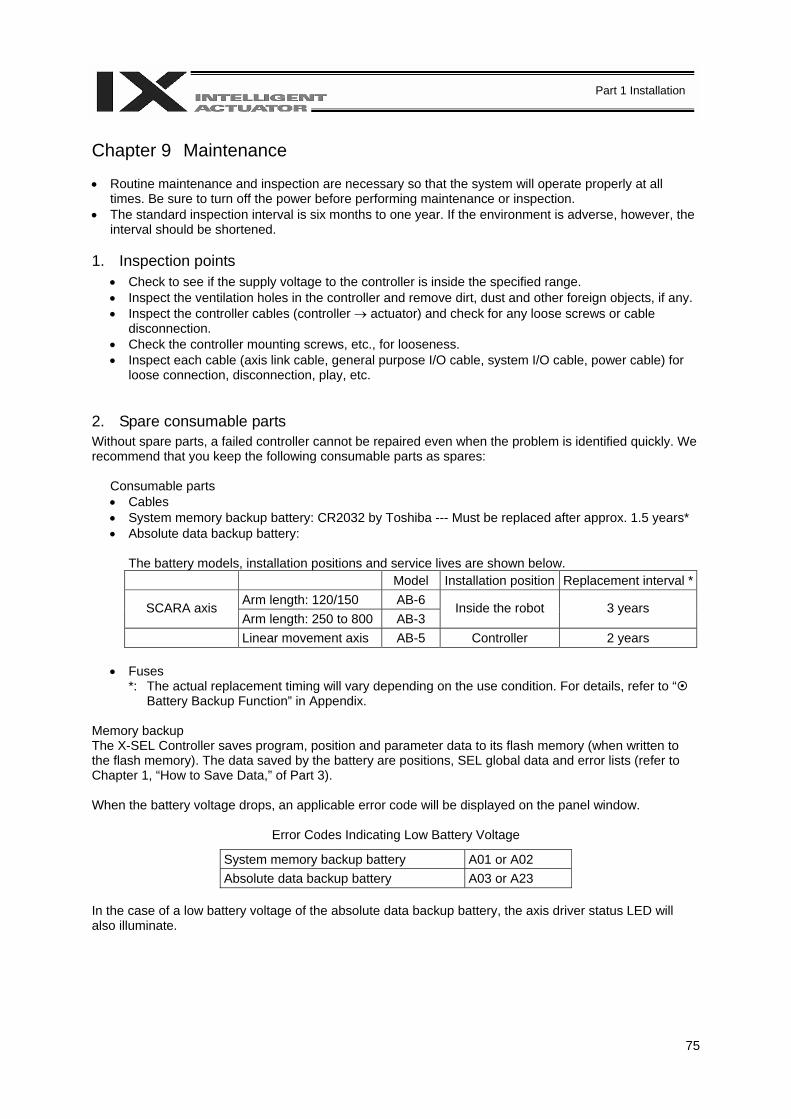
75
Part 1 Installation
Chapter 9 Maintenance • Routine maintenance and inspection are necessary so that the system will operate properly at all
times. Be sure to turn off the power before performing maintenance or inspection. • The standard inspection interval is six months to one year. If the environment is adverse, however, the
interval should be shortened. 1. Inspection points
• Check to see if the supply voltage to the controller is inside the specified range. • Inspect the ventilation holes in the controller and remove dirt, dust and other foreign objects, if any. • Inspect the controller cables (controller → actuator) and check for any loose screws or cable
disconnection. • Check the controller mounting screws, etc., for looseness. • Inspect each cable (axis link cable, general purpose I/O cable, system I/O cable, power cable) for
loose connection, disconnection, play, etc. 2. Spare consumable parts Without spare parts, a failed controller cannot be repaired even when the problem is identified quickly. We recommend that you keep the following consumable parts as spares:
Consumable parts • Cables • System memory backup battery: CR2032 by Toshiba --- Must be replaced after approx. 1.5 years* • Absolute data backup battery:
The battery models, installation positions and service lives are shown below. Model Installation position Replacement interval *
Arm length: 120/150 AB-6 SCARA axis Arm length: 250 to 800 AB-3
Inside the robot 3 years
Linear movement axis AB-5 Controller 2 years • Fuses
*: The actual replacement timing will vary depending on the use condition. For details, refer to “ Battery Backup Function” in Appendix.
Memory backup The X-SEL Controller saves program, position and parameter data to its flash memory (when written to the flash memory). The data saved by the battery are positions, SEL global data and error lists (refer to Chapter 1, “How to Save Data,” of Part 3). When the battery voltage drops, an applicable error code will be displayed on the panel window.
Error Codes Indicating Low Battery Voltage
System memory backup battery A01 or A02 Absolute data backup battery A03 or A23
In the case of a low battery voltage of the absolute data backup battery, the axis driver status LED will also illuminate.

76
Part 1 Installation
3. Replacement Procedure for System Memory Backup Battery Backing up the system memory If “Other parameter No. 20, Backup battery installation function type” is set to “2” (installed), the following SRAM data in the X-SEL Controller will be backed up by the system memory backup battery on the panel board: • Position data • SEL global data (flags, integer/real variables, string variables) • Error lists Therefore, the above SRAM data will be destroyed if the system memory backup battery is removed when “Other parameter No. 20, Backup battery installation function type” is set to “2” (installed). For this reason, always follow the procedure below when replacing the system-memory backup battery: (1) Turn on the controller power. (2) Record (write down) the current setting of “Other parameter No. 20, Backup battery installation
function type” (this will be used when reverting the parameter to its original setting following the replacement of system memory backup battery).
(3) If the PC software is installed on your PC, save the position data to a file using the PC software. The
data will be used in case the SRAM data saved to the flash ROM fails. (4) Change “Other parameter No. 20, Backup battery installation function type” to “1” and transfer the
setting to the controller, and then perform a flash ROM write (the point data will be saved to the flash ROM).
* Confirm that the flash ROM writing process has completed.
(5) Perform a software reset to restart the controller (the SEL global data and error lists will be saved to
the special area in the flash ROM). (6) When the controller has been restarted, turn off the power.
* Once the controller has been restarted, be sure to keep the power on until the initialization sequence number is no longer displayed on the panel window (while “InXX” is displayed following “8888.” XX indicates a number).
(7) Replace the system memory backup battery (SRAM data will be destroyed if steps 1 through 6 are
not performed properly).
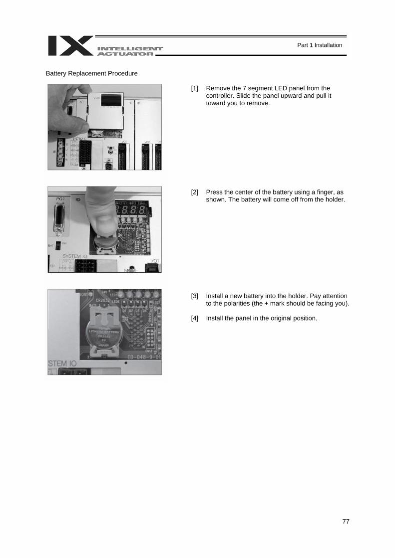
77
Part 1 Installation
Battery Replacement Procedure
[1] Remove the 7 segment LED panel from the
controller. Slide the panel upward and pull it toward you to remove.
[2] Press the center of the battery using a finger, as
shown. The battery will come off from the holder. [3] Install a new battery into the holder. Pay attention
to the polarities (the + mark should be facing you). [4] Install the panel in the original position.

78
Part 1 Installation
(8) When the replacement of system memory backup battery is complete, confirm that the battery is
installed securely and then turn on the controller power. (9) Revert “Other parameter No. 20, Backup battery installation function type” to the value recorded in
step 2, transfer the setting to the controller, and then perform a flash ROM write.
* Confirm that the flash ROM writing process has completed. (10) Perform a software reset (restart the controller). (11) After the controller has restarted, confirm that the SRAM data have been restored.
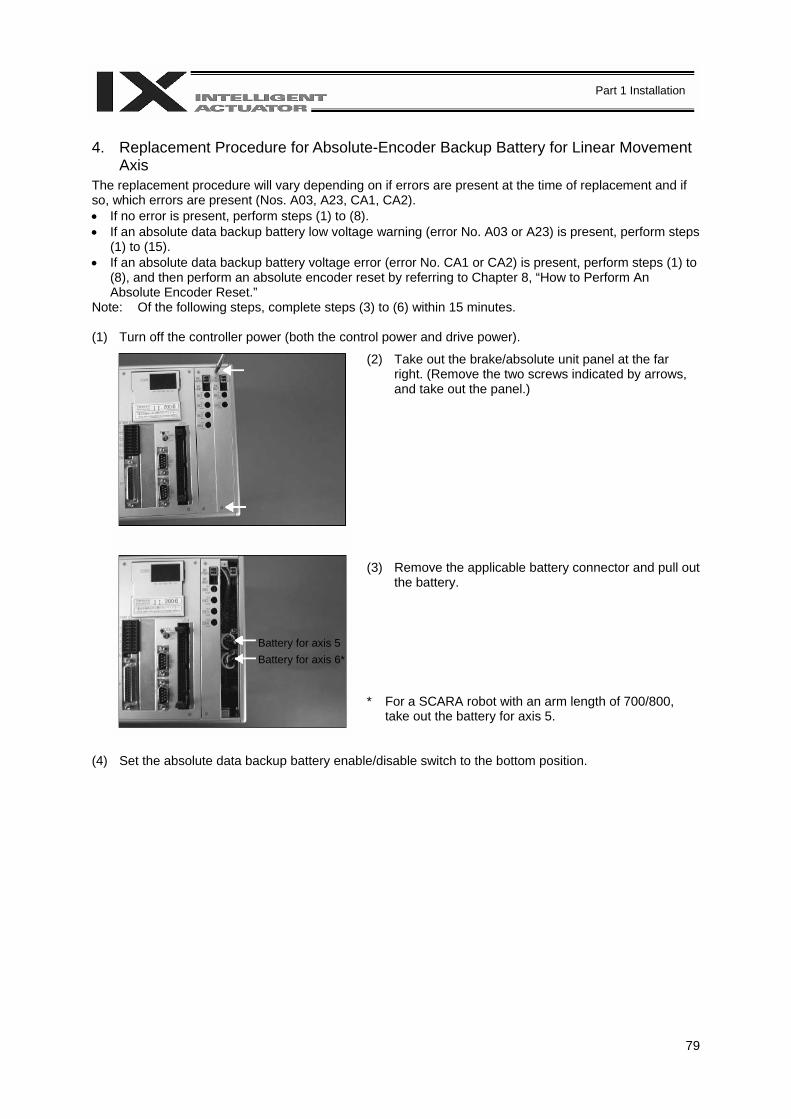
79
Part 1 Installation
4. Replacement Procedure for Absolute-Encoder Backup Battery for Linear Movement
Axis The replacement procedure will vary depending on if errors are present at the time of replacement and if so, which errors are present (Nos. A03, A23, CA1, CA2). • If no error is present, perform steps (1) to (8). • If an absolute data backup battery low voltage warning (error No. A03 or A23) is present, perform steps
(1) to (15). • If an absolute data backup battery voltage error (error No. CA1 or CA2) is present, perform steps (1) to
(8), and then perform an absolute encoder reset by referring to Chapter 8, “How to Perform An Absolute Encoder Reset.”
Note: Of the following steps, complete steps (3) to (6) within 15 minutes. (1) Turn off the controller power (both the control power and drive power).
(2) Take out the brake/absolute unit panel at the far right. (Remove the two screws indicated by arrows, and take out the panel.)
(3) Remove the applicable battery connector and pull out the battery.
* For a SCARA robot with an arm length of 700/800, take out the battery for axis 5.
(4) Set the absolute data backup battery enable/disable switch to the bottom position.
Battery for axis 5 Battery for axis 6*
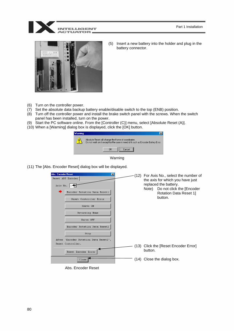
80
Part 1 Installation
(5) Insert a new battery into the holder and plug in the
battery connector. (6) Turn on the controller power. (7) Set the absolute data backup battery enable/disable switch to the top (ENB) position. (8) Turn off the controller power and install the brake switch panel with the screws. When the switch
panel has been installed, turn on the power. (9) Start the PC software online. From the [Controller (C)] menu, select [Absolute Reset (A)]. (10) When a [Warning] dialog box is displayed, click the [OK] button.
Warning (11) The [Abs. Encoder Reset] dialog box will be displayed.
(12) For Axis No., select the number of the axis for which you have just replaced the battery. Note) Do not click the [Encoder
Rotation Data Reset 1] button.
(13) Click the [Reset Encoder Error] button.
(14) Close the dialog box.
Abs. Encoder Reset
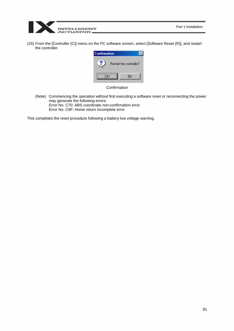
81
Part 1 Installation
(15) From the [Controller (C)] menu on the PC software screen, select [Software Reset (R)], and restart
the controller.
Confirmation
(Note) Commencing the operation without first executing a software reset or reconnecting the power may generate the following errors: Error No. C70: ABS coordinate non-confirmation error Error No. C6F: Home return incomplete error
This completes the reset procedure following a battery low voltage warning.
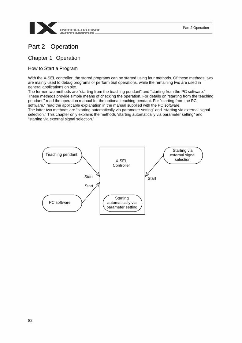
82
Part 2 Operation
Part 2 Operation Chapter 1 Operation How to Start a Program With the X-SEL controller, the stored programs can be started using four methods. Of these methods, two are mainly used to debug programs or perform trial operations, while the remaining two are used in general applications on site. The former two methods are “starting from the teaching pendant” and “starting from the PC software.” These methods provide simple means of checking the operation. For details on “starting from the teaching pendant,” read the operation manual for the optional teaching pendant. For “starting from the PC software,” read the applicable explanation in the manual supplied with the PC software. The latter two methods are “starting automatically via parameter setting” and “starting via external signal selection.” This chapter only explains the methods “starting automatically via parameter setting” and “starting via external signal selection.”
Teaching pendant
Start Start
PC software
X-SEL Controller
Starting automatically via parameter setting
Starting via external signal
selection
Start
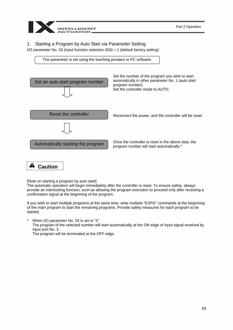
83
Part 2 Operation
1. Starting a Program by Auto Start via Parameter Setting I/O parameter No. 33 (input function selection 003) = 1 (default factory setting)
Set the number of the program you wish to start automatically in other parameter No. 1 (auto start program number). Set the controller mode to AUTO.
Reconnect the power, and the controller will be reset. Once the controller is reset in the above step, the program number will start automatically.*
Caution [Note on starting a program by auto start] The automatic operation will begin immediately after the controller is reset. To ensure safety, always provide an interlocking function, such as allowing the program execution to proceed only after receiving a confirmation signal at the beginning of the program. If you wish to start multiple programs at the same time, write multiple “EXPG” commands at the beginning of the main program to start the remaining programs. Provide safety measures for each program to be started. * When I/O parameter No. 33 is set to “2”
The program of the selected number will start automatically at the ON edge of input signal received by input port No. 3. The program will be terminated at the OFF edge.
Set an auto start program number
Reset the controller
Automatically starting the program
This parameter is set using the teaching pendant or PC software.
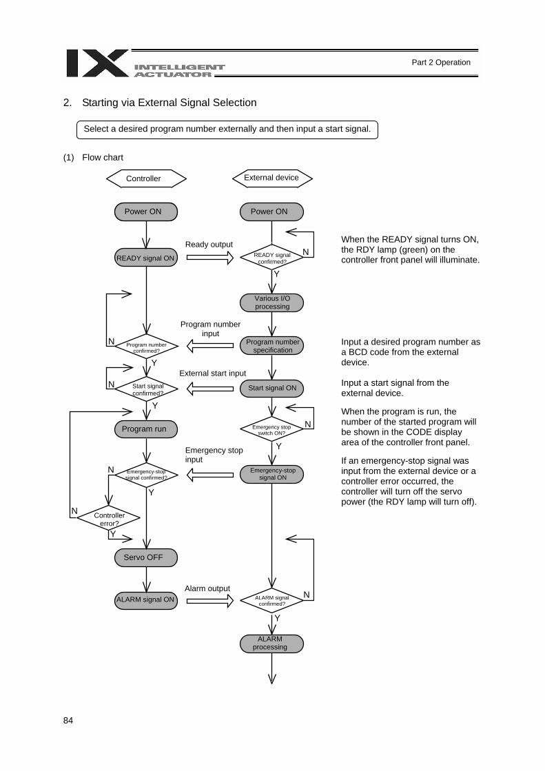
84
Part 2 Operation
2. Starting via External Signal Selection (1) Flow chart
When the READY signal turns ON, the RDY lamp (green) on the controller front panel will illuminate.
Input a desired program number as a BCD code from the external device. Input a start signal from the external device. When the program is run, the number of the started program will be shown in the CODE display area of the controller front panel. If an emergency-stop signal was input from the external device or a controller error occurred, the controller will turn off the servo power (the RDY lamp will turn off).
Select a desired program number externally and then input a start signal.
Controller
Power ON
READY signal ON
Program number confirmed?
N
N
N
N
Y
Y
Y
N
N
Y
N
Y
Start signal confirmed?
Program run
Emergency-stop signal confirmed?
Controller error?
Servo OFF
ALARM signal ON Alarm output
Emergency stop input
External start input
Program number input
Ready output
External device
Power ON
READY signal confirmed?
Various I/O processing
Program number specification
Start signal ON
Emergency stop switch ON?
Emergency-stop signal ON
ALARM signal confirmed?
ALARM processing
Y
Y
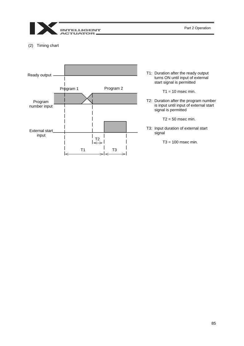
85
Part 2 Operation
(2) Timing chart
T1: Duration after the ready output turns ON until input of external start signal is permitted
T1 = 10 msec min.
T2: Duration after the program number
is input until input of external start signal is permitted
T2 = 50 msec min.
T3: Input duration of external start
signal
T3 = 100 msec min.
Ready output
Program number input
Program 1 Program 2
External start input
T1
T2
T3

86
Part 2 Operation
3. Drive Source Recovery Request and Operation Pause Reset Request (1) Drive source recovery request
[1] How to request a drive source recovery A drive source recovery request can be issued using one of the following methods: • Set I/O parameter No. 44 to “1” (Input selection function 014 = Drive-source cutoff reset
input), then input the ON edge to input port No. 14. • Select [Drive Source Recovery Request (P)] from the [Controller (C)] menu on the PC
software screen. • Select Ctl (controller operation) and RPwr (drive source recovery request) on the mode
selection screen of the teaching pendant.
[2] Case where a drive source request is required A drive source recovery request is required in the following case: • A drive-source cutoff factor occurred when I/O parameter No. 44 was set to “1” → Recovery
after the cutoff factor is removed. (2) Operation pause reset request
[1] How to request an operation pause reset An operation pause reset request can be issued using one of the following methods: • Set I/O parameter No. 35 to “1” (Input selection function 005 = Operation-pause reset signal),
then input the ON edge to input port No. 5. • Select [Operation Pause Reset Request (L)] from the [Controller (C)] menu on the PC
software screen. • Select Ctl (controller operation) and RAct (operation pause reset request) on the mode
selection screen of the teaching pendant. [2] Cases where an operation pause reset request is required
An operation pause reset request is required in any of the following cases: • An emergency stop was actuated during automatic operation when other parameter No. 10
was set to “2” (Emergency stop recovery type = Continued operation, and only during automatic operation) → Recovery (reset of operation pause) after the emergency stop is reset.
• The automatic operation was stopped using the deadman switch or enable switch when other parameter No. 11 was set to “2” (Deadman/enable switch recovery type = Continued operation) (only during automatic operation) → Recovery (reset of operation pause) after the stop is reset.
• An OFF input signal was received by input port No. 6 when I/O parameter No. 36 was set to ”1” (Input selection function 006 = Operation pause signal) → Recovery (reset of operation pause) after an ON-level input signal is received by input port No. 6.
* If the case in 2 of (1) and any of the cases in 2 of (2) are present at the same time, a drive
source recovery request must be issued first, followed by an operation pause reset request.
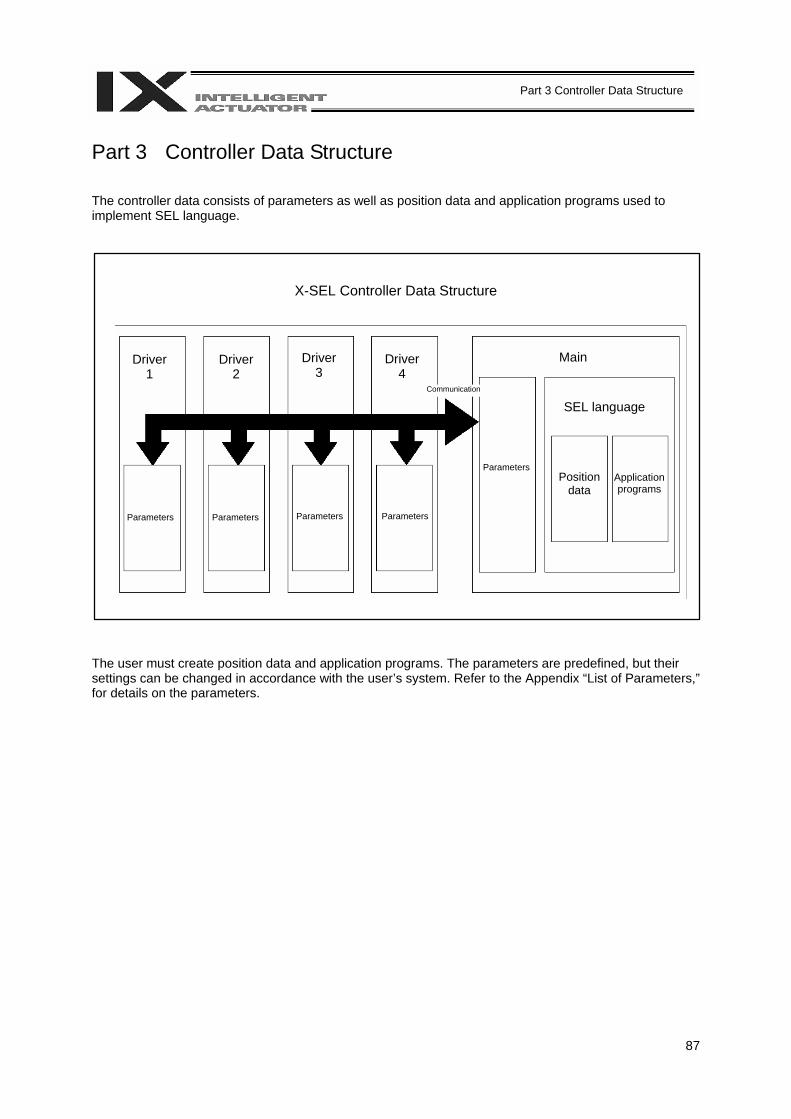
87
Part 3 Controller Data Structure
Part 3 Controller Data Structure The controller data consists of parameters as well as position data and application programs used to implement SEL language.
X-SEL Controller Data Structure The user must create position data and application programs. The parameters are predefined, but their settings can be changed in accordance with the user’s system. Refer to the Appendix “List of Parameters,” for details on the parameters.
Driver 1
Driver 2
Driver 3
Driver 4
Parameters Parameters Parameters Parameters
Parameters
Communication
Main
SEL language
Position data
Application programs
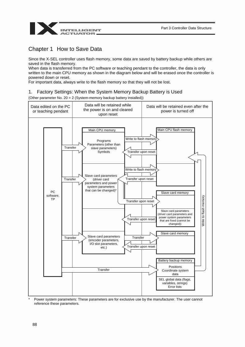
88
Part 3 Controller Data Structure
Chapter 1 How to Save Data Since the X-SEL controller uses flash memory, some data are saved by battery backup while others are saved in the flash memory. When data is transferred from the PC software or teaching pendant to the controller, the data is only written to the main CPU memory as shown in the diagram below and will be erased once the controller is powered down or reset. For important data, always write to the flash memory so that they will not be lost. 1. Factory Settings: When the System Memory Backup Battery is Used (Other parameter No. 20 = 2 (System-memory backup battery installed))
* Power system parameters: These parameters are for exclusive use by the manufacturer. The user cannot reference these parameters.
Data edited on the PC or teaching pendant
Data will be retained while the power is on and cleared
upon reset
Data will be retained even after the power is turned off
PC software,
TP
Transfer
Transfer
Transfer
Main CPU memory
Programs Parameters (other than
slave parameters) Symbols
Slave card parameters (driver card
parameters and power system parameters
that can be changed)*
Slave card parameters (encoder parameters, I/O slot parameters,
etc.)
Write to flash memory
Write to flash memory
Transfer upon reset
Transfer upon reset
Transfer upon reset
Transfer upon reset
Transfer upon reset
Transfer
Transfer
Main CPU flash memory
Slave card memory
Slave card memory
Slave card parameters (driver card parameters and power system parameters that are fixed (cannot be
changed))
Battery backup memory Positions
Coordinate system data
SEL global data (flags, variables, strings)
Error lists
Writ
e to
flas
h m
emor
y
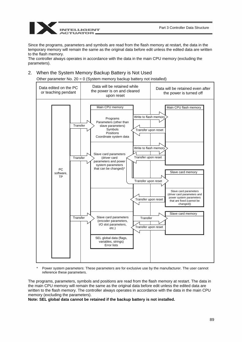
89
Part 3 Controller Data Structure
Since the programs, parameters and symbols are read from the flash memory at restart, the data in the temporary memory will remain the same as the original data before edit unless the edited data are written to the flash memory. The controller always operates in accordance with the data in the main CPU memory (excluding the parameters). 2. When the System Memory Backup Battery is Not Used
Other parameter No. 20 = 0 (System memory backup battery not installed)
* Power system parameters: These parameters are for exclusive use by the manufacturer. The user cannot
reference these parameters. The programs, parameters, symbols and positions are read from the flash memory at restart. The data in the main CPU memory will remain the same as the original data before edit unless the edited data are written to the flash memory. The controller always operates in accordance with the data in the main CPU memory (excluding the parameters). Note: SEL global data cannot be retained if the backup battery is not installed.
Data edited on the PC or teaching pendant
Data will be retained while the power is on and cleared
upon reset
Data will be retained even after the power is turned off
PC software,
TP
Transfer
Transfer
Transfer
Main CPU memory
Programs Parameters (other than
slave parameters) Symbols Positions
Coordinate system data
Slave card parameters (driver card
parameters and power system parameters
that can be changed)*
Slave card parameters (encoder parameters, I/O slot parameters,
etc.)
Write to flash memory
Write to flash memory
Transfer upon reset
Transfer upon reset
Transfer upon reset
Transfer upon reset
Transfer upon reset
Transfer
Main CPU flash memory
Slave card memory
Slave card memory
Slave card parameters (driver card parameters and power system parameters that are fixed (cannot be
changed))
SEL global data (flags, variables, strings)
Error lists

90
Part 3 Controller Data Structure
3. Points to Note
Point to note when transferring data and writing to the flash memory Never turn off the main power while data is being transferred or written to the flash memory. The data will be lost and the controller operation may be disabled.
Point to note when saving parameters to a file The encoder parameters are stored in the EEPROM of the actuator’s encoder itself (unlike other parameters, they are not stored in the EEPROM of the controller). The encoder parameters will be read from the encoder’s EEPROM to the controller when the power is turned on or upon software reset. Therefore, if the parameters are saved to a file after turning on the controller (or restarting it via a software reset) without an actuator (encoder) connected, the encoder parameters saved to the file will become invalid.
Point to note when transferring a parameter file to the controller
When a parameter file is transferred to the controller, the encoder parameters will be transferred to the EEPROM of the encoder (excluding manufacturing/function information). Therefore, if the parameter file transferred to the controller has been read from a controller that was started without an actuator connected, invalid encoder parameters will be written to the encoder’s EEPROM (provided that an actuator is connected to the controller to which the file was transferred). When saving the parameters to a file, do so with an actuator connected to the controller.
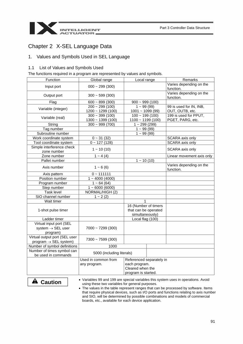
91
Part 3 Controller Data Structure
Chapter 2 X-SEL Language Data 1. Values and Symbols Used in SEL Language 1.1 List of Values and Symbols Used The functions required in a program are represented by values and symbols.
Function Global range Local range Remarks
Input port 000 ~ 299 (300) Varies depending on the function.
Output port 300 ~ 599 (300) Varies depending on the function.
Flag 600 ~ 899 (300) 900 ~ 999 (100)
Variable (integer) 200 ~ 299 (100) 1200 ~ 1299 (100)
1 ~ 99 (99) 1001 ~ 1099 (99)
99 is used for IN, INB, OUT, OUTB, etc.
Variable (real) 300 ~ 399 (100) 1300 ~ 1399 (100)
100 ~ 199 (100) 1100 ~ 1199 (100)
199 is used for PPUT, PGET, PARG, etc.
String 300 ~ 999 (700) 1 ~ 299 (299) Tag number 1 ~ 99 (99)
Subroutine number 1 ~ 99 (99) Work coordinate system 0 ~ 31 (32) SCARA axis only Tool coordinate system 0 ~ 127 (128) SCARA axis only
Simple interference check zone number 1 ~ 10 (10) SCARA axis only
Zone number 1 ~ 4 (4) Linear movement axis onlyPallet number 1 ~ 10 (10)
Axis number 1 ~ 6 (6) Varies depending on the function.
Axis pattern 0 ~ 111111 Position number 1 ~ 4000 (4000) Program number 1 ~ 64 (64)
Step number 1 ~ 6000 (6000) Task level NORMAL/HIGH (2)
SIO channel number 1 ~ 2 (2) Wait timer 1
1-shot pulse timer 16 (Number of timers that can be operated
simultaneously)
Ladder timer Local flag (100) Virtual input port (SEL system → SEL user
program) 7000 ~ 7299 (300)
Virtual output port (SEL user program → SEL system) 7300 ~ 7599 (300)
Number of symbol definitions 1000 Number of times symbol can
be used in commands 5000 (including literals)
Used in common from any program.
Referenced separately in each program. Cleared when the program is started.
Caution
• Variables 99 and 199 are special variables this system uses in operations. Avoid using these two variables for general purposes.
• The values in the table represent ranges that can be processed by software. Items that require physical devices, such as I/O ports and functions relating to axis number and SIO, will be determined by possible combinations and models of commercial boards, etc., available for each device application.

92
Part 3 Controller Data Structure
The variables and flags in the global range will be retained even after the controller power is turned off
(when other parameter No. 20 is set to “2.” Refer to Chapter 1, “How to Save Data,” of Part 3).
The variables and flags in the local range will be cleared when the program is started.
Ranges of values that can be used in SEL language Integers and real numbers can be used. However, pay due attention to the following limitations:
[1] Numeric data
The X-SEL Controller can handle values of maximum eight digits including a sign and a decimal point. Integer: -9,999,999 to 99,999,999 Real number: Maximum eight digits including a sign and decimal point, regardless of the size of value Example) 999999.9, 0.123456, -0.12345 If a floating point is used in operations, the number of valid digits will be limited to seven. Also note that operations using a floating point are subject to error.
[2] Position data
The input range of position data consists of four integer digits and three decimal digits. –9999.999 to 9999.99 (the maximum value varies depending on the actuator model). If position data are used in internal operations as numeric data (repeated multiplications and divisions), the accuracy of the last digit may decrease.
Consider the above limitations fully when using values. Particularly when the CPEQ command is used in a comparison operation using real numbers, a match will rarely result. In this case, the CPLE or CPGE command that looks at the magnitude relationship of two terms must be used. 1.2 I/O Ports (1) Input ports
Used as input ports for limit switches, sensor switches, etc.
Input number assignment 000 to 031 (standard)
(2) Output ports
Used as various output ports.
Output number assignment 300 to 315 (standard)
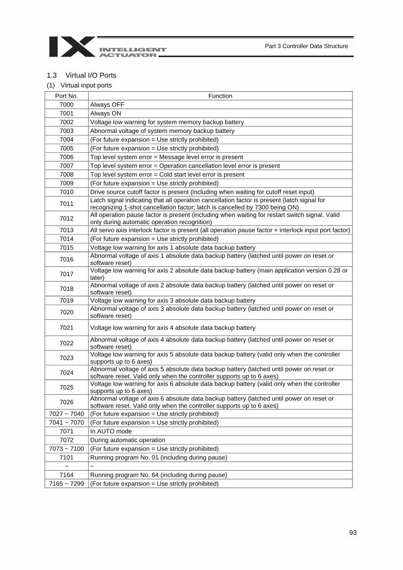
93
Part 3 Controller Data Structure
1.3 Virtual I/O Ports (1) Virtual input ports
Port No. Function 7000 Always OFF 7001 Always ON 7002 Voltage low warning for system memory backup battery 7003 Abnormal voltage of system memory backup battery 7004 (For future expansion = Use strictly prohibited) 7005 (For future expansion = Use strictly prohibited) 7006 Top level system error = Message level error is present 7007 Top level system error = Operation cancellation level error is present 7008 Top level system error = Cold start level error is present 7009 (For future expansion = Use strictly prohibited) 7010 Drive source cutoff factor is present (including when waiting for cutoff reset input)
7011 Latch signal indicating that all operation cancellation factor is present (latch signal for recognizing 1-shot cancellation factor; latch is cancelled by 7300 being ON)
7012 All operation pause factor is present (including when waiting for restart switch signal. Valid only during automatic operation recognition)
7013 All servo axis interlock factor is present (all operation pause factor + interlock input port factor)7014 (For future expansion = Use strictly prohibited) 7015 Voltage low warning for axis 1 absolute data backup battery
7016 Abnormal voltage of axis 1 absolute data backup battery (latched until power on reset or software reset)
7017 Voltage low warning for axis 2 absolute data backup battery (main application version 0.28 or later)
7018 Abnormal voltage of axis 2 absolute data backup battery (latched until power on reset or software reset)
7019 Voltage low warning for axis 3 absolute data backup battery
7020 Abnormal voltage of axis 3 absolute data backup battery (latched until power on reset or software reset)
7021 Voltage low warning for axis 4 absolute data backup battery
7022 Abnormal voltage of axis 4 absolute data backup battery (latched until power on reset or software reset)
7023 Voltage low warning for axis 5 absolute data backup battery (valid only when the controller supports up to 6 axes)
7024 Abnormal voltage of axis 5 absolute data backup battery (latched until power on reset or software reset. Valid only when the controller supports up to 6 axes)
7025 Voltage low warning for axis 6 absolute data backup battery (valid only when the controller supports up to 6 axes)
7026 Abnormal voltage of axis 6 absolute data backup battery (latched until power on reset or software reset. Valid only when the controller supports up to 6 axes)
7027 ~ 7040 (For future expansion = Use strictly prohibited) 7041 ~ 7070 (For future expansion = Use strictly prohibited)
7071 In AUTO mode 7072 During automatic operation
7073 ~ 7100 (For future expansion = Use strictly prohibited) 7101 Running program No. 01 (including during pause)
~ ~ 7164 Running program No. 64 (including during pause)
7165 ~ 7299 (For future expansion = Use strictly prohibited)
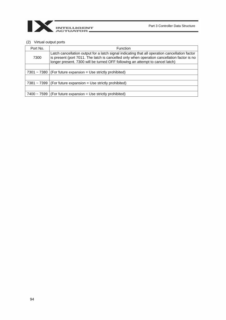
94
Part 3 Controller Data Structure
(2) Virtual output ports
Port No. Function
7300 Latch cancellation output for a latch signal indicating that all operation cancellation factor is present (port 7011. The latch is cancelled only when operation cancellation factor is no longer present. 7300 will be turned OFF following an attempt to cancel latch)
7301 ~ 7380 (For future expansion = Use strictly prohibited)
7381 ~ 7399 (For future expansion = Use strictly prohibited)
7400 ~ 7599 (For future expansion = Use strictly prohibited)
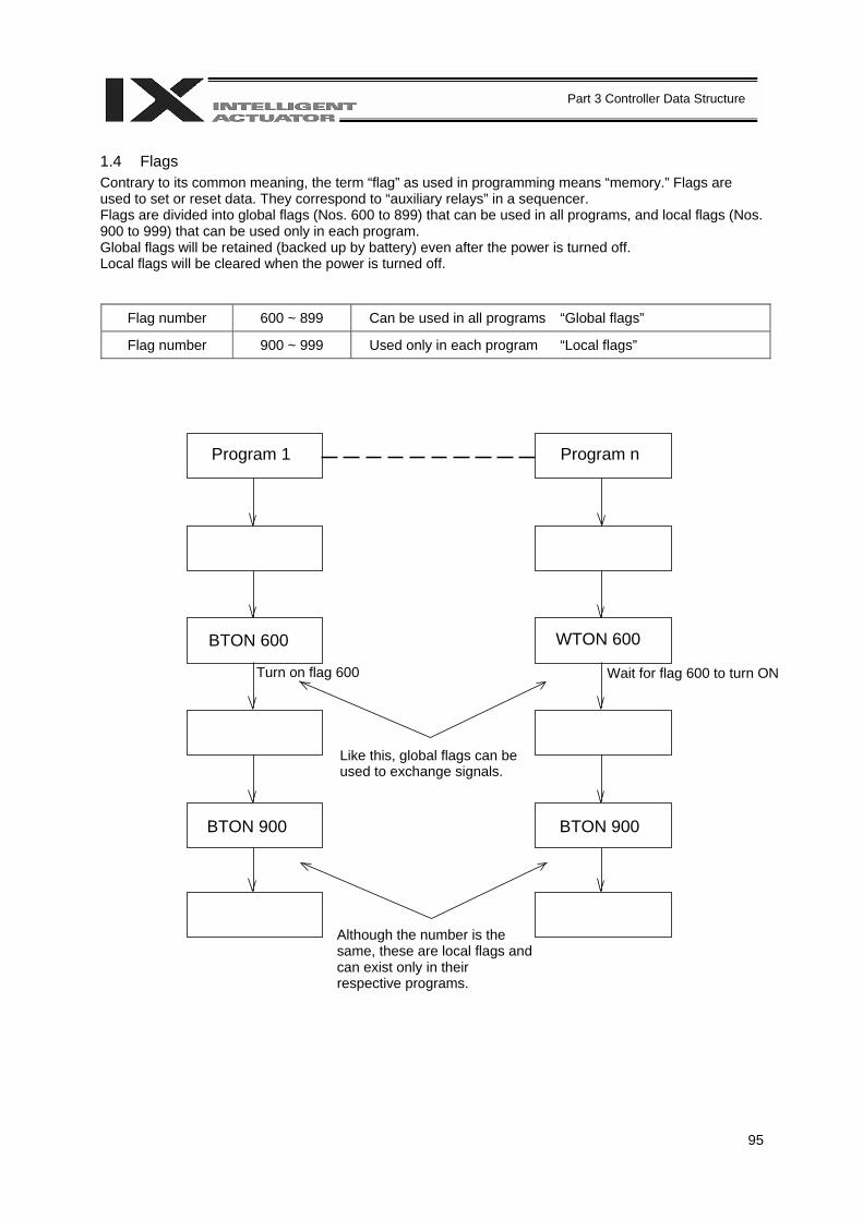
95
Part 3 Controller Data Structure
1.4 Flags Contrary to its common meaning, the term “flag” as used in programming means “memory.” Flags are used to set or reset data. They correspond to “auxiliary relays” in a sequencer. Flags are divided into global flags (Nos. 600 to 899) that can be used in all programs, and local flags (Nos. 900 to 999) that can be used only in each program. Global flags will be retained (backed up by battery) even after the power is turned off. Local flags will be cleared when the power is turned off.
Flag number 600 ~ 899 Can be used in all programs “Global flags”
Flag number 900 ~ 999 Used only in each program “Local flags”
Program 1 Program n
BTON 600 WTON 600
BTON 900 BTON 900
Turn on flag 600 Wait for flag 600 to turn ON
Like this, global flags can be used to exchange signals.
Although the number is the same, these are local flags and can exist only in their respective programs.
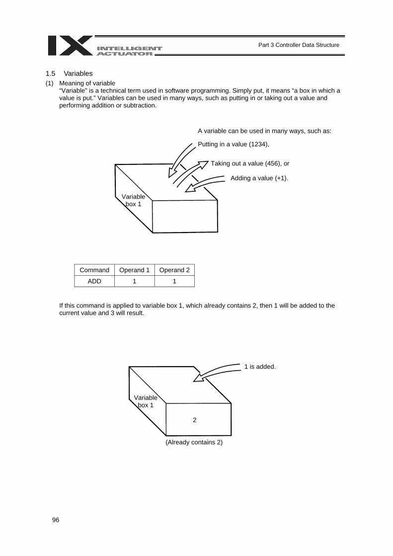
96
Part 3 Controller Data Structure
1.5 Variables (1) Meaning of variable
“Variable” is a technical term used in software programming. Simply put, it means “a box in which a value is put.” Variables can be used in many ways, such as putting in or taking out a value and performing addition or subtraction.
Command Operand 1 Operand 2
ADD 1 1
If this command is applied to variable box 1, which already contains 2, then 1 will be added to the current value and 3 will result.
Variable box 1
A variable can be used in many ways, such as: Putting in a value (1234),
Taking out a value (456), or
Adding a value (+1).
Variable box 1
1 is added.
(Already contains 2)
2
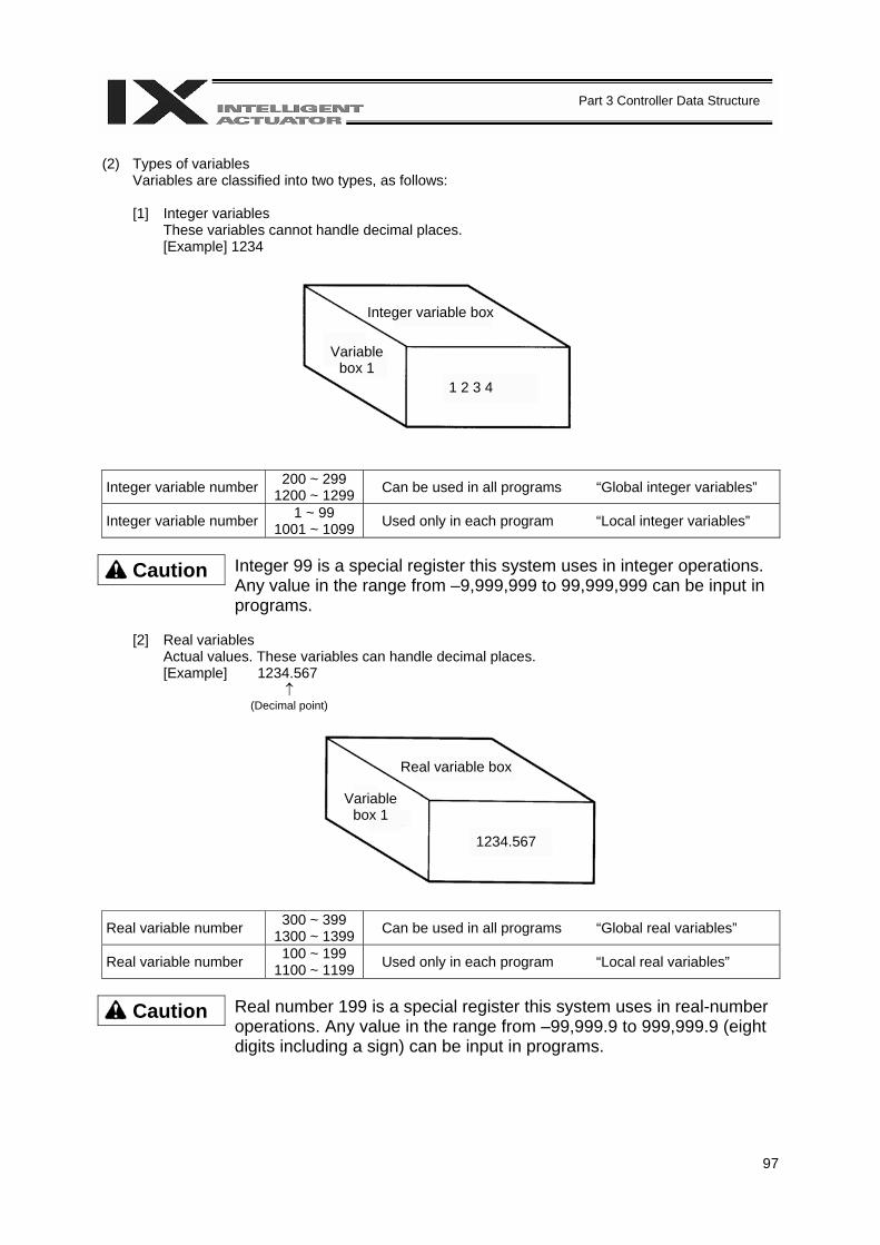
97
Part 3 Controller Data Structure
(2) Types of variables
Variables are classified into two types, as follows:
[1] Integer variables These variables cannot handle decimal places. [Example] 1234
Integer variable number 200 ~ 299 1200 ~ 1299 Can be used in all programs “Global integer variables”
Integer variable number 1 ~ 99 1001 ~ 1099 Used only in each program “Local integer variables”
Caution
Integer 99 is a special register this system uses in integer operations. Any value in the range from –9,999,999 to 99,999,999 can be input in programs.
[2] Real variables
Actual values. These variables can handle decimal places. [Example] 1234.567
↑ (Decimal point)
Real variable number 300 ~ 399 1300 ~ 1399 Can be used in all programs “Global real variables”
Real variable number 100 ~ 199 1100 ~ 1199 Used only in each program “Local real variables”
Caution
Real number 199 is a special register this system uses in real-number operations. Any value in the range from –99,999.9 to 999,999.9 (eight digits including a sign) can be input in programs.
1 2 3 4
Integer variable box
Variable box 1
Real variable box
1234.567
Variable box 1
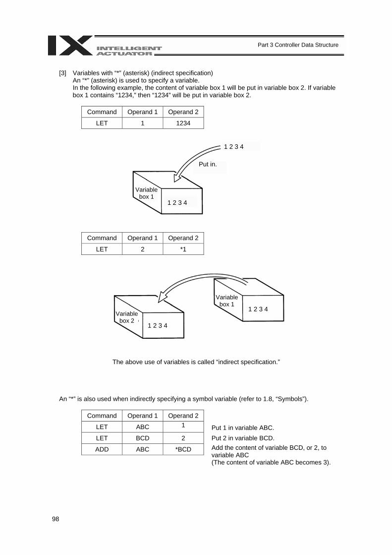
98
Part 3 Controller Data Structure
[3] Variables with “*” (asterisk) (indirect specification)
An “*” (asterisk) is used to specify a variable. In the following example, the content of variable box 1 will be put in variable box 2. If variable box 1 contains “1234,” then “1234” will be put in variable box 2.
Command Operand 1 Operand 2
LET 1 1234
Command Operand 1 Operand 2
LET 2 *1
The above use of variables is called “indirect specification.”
An “*” is also used when indirectly specifying a symbol variable (refer to 1.8, “Symbols”).
Command Operand 1 Operand 2
LET ABC 1
LET BCD 2
ADD ABC *BCD
Variable box 1
1 2 3 4
1 2 3 4
Put in.
Variable box 1
Variable box 2
1 2 3 4
1 2 3 4
Put 1 in variable ABC.
Put 2 in variable BCD.
Add the content of variable BCD, or 2, to variable ABC (The content of variable ABC becomes 3).
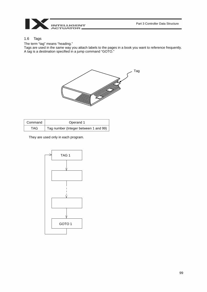
99
Part 3 Controller Data Structure
1.6 Tags The term “tag” means “heading.” Tags are used in the same way you attach labels to the pages in a book you want to reference frequently. A tag is a destination specified in a jump command “GOTO.”
Command Operand 1
TAG Tag number (Integer between 1 and 99)
They are used only in each program.
Tag
TAG 1
GOTO 1
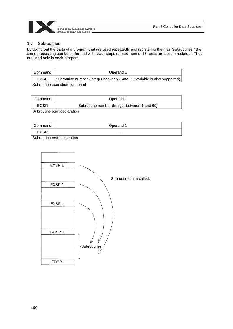
100
Part 3 Controller Data Structure
1.7 Subroutines By taking out the parts of a program that are used repeatedly and registering them as “subroutines,” the same processing can be performed with fewer steps (a maximum of 15 nests are accommodated). They are used only in each program.
Command Operand 1
EXSR Subroutine number (Integer between 1 and 99; variable is also supported) Subroutine execution command
Command Operand 1
BGSR Subroutine number (Integer between 1 and 99) Subroutine start declaration
Command Operand 1
EDSR ⎯ Subroutine end declaration
Subroutines are called.
Subroutines
EXSR 1
EXSR 1
EXSR 1
BGSR 1
EDSR
101
Part 3 Controller Data Structure
1.8 Symbols In the X-SEL Controller, values such as variable numbers and flag numbers can be handled as symbols. For the method to edit symbols, refer to “Editing Symbols” in the operation manual for X-SEL teaching pendant or “Symbol Edit Window” in the operation manual for X-SEL PC software. (1) Supported symbols
The following items can be expressed using symbols: Variable number, flag number, tag number, subroutine number, program number, position number, input port number, output port number, axis number, or a constant.
(2) Description rules of symbols
[1] A maximum of nine bytes are used to represent alphanumeric characters (the length of a character string literal must not exceed eight characters). * If the PC software version is 1.1.0.5 or later or the teaching pendant version is 1.04 or later,
an underscore can be used as the first character in a symbol. * If the PC software version is 1.1.05 or later, one byte ASCII code characters from 21h to 7Eh
(limited to those that can be input via keyboard) can be used as the second and subsequent characters.
* Exercise caution that the same ASCII code may be expressed differently between the PC software and the teaching pendant because of the different fonts used by the two (the same applies to character string literals).
5Ch --- PC software: Backslash \ (overseas specifications, etc.) Teaching pendant: Yen mark ¥
7Eh --- PC software: ~ Teaching pendant: Right arrow →
[2] Symbols of the same name must not be defined within each function (the same local symbol can be used in different programs).
[3] Symbols of the same name must not be defined within the flag number, input port number or output port number group (the same local symbol can be used in different programs).
[4] Symbols of the same name must not be defined within the integer variable number or real variable number group (the same local symbol can be used in different programs).
[5] Symbols of the same name must not be defined within the integer constant or real constant group.
(3) Number of symbols that can be defined: Maximum 1000 (4) Number of times symbols can be used in all SEL programs: Maximum 5000 times including character
string literals * If symbol is used in all of the input condition, operand 1, operand 2 and output fields, it is deemed
that symbol is used four times in one step. 1.9 Character String Literals Character string literals are used in certain string operation commands and consist of the portion enclosed by single quotation marks (‘ ‘) (maximum eight one byte characters). With the PC software, single byte ASCII code characters from 20h to 7Eh (limited to those that can be input via keyboard) can be used inside the single quotation marks. With the teaching pendant, single byte alphanumeric characters and single byte underscores can be used.
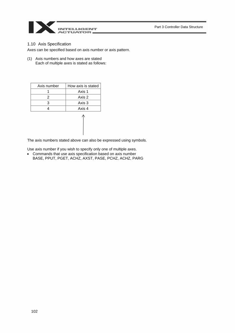
102
Part 3 Controller Data Structure
1.10 Axis Specification Axes can be specified based on axis number or axis pattern. (1) Axis numbers and how axes are stated
Each of multiple axes is stated as follows:
Axis number How axis is stated1 Axis 1 2 Axis 2 3 Axis 3 4 Axis 4
The axis numbers stated above can also be expressed using symbols. Use axis number if you wish to specify only one of multiple axes. • Commands that use axis specification based on axis number
BASE, PPUT, PGET, ACHZ, AXST, PASE, PCHZ, ACHZ, PARG

103
Part 3 Controller Data Structure
(2) Axis pattern
Whether or not each axis will be used is indicated by “1” or “0.”
(Upper) (Lower)
Axis number Axis 4 Axis 3 Axis 2 Axis 1 Used 1 1 1 1
Not used 0 0 0 0 [Example] When axes 1 and 2 are used
Axis 2 ↓
0011 --- The two 0s in front are not necessary. With the 0s removed, the expression reads “11.”
↑ Axis 1
[Example] When axes 1 and 4 are used
Axis 4 ↓ 1001 --- In this case, the 0s are needed to indicate the position of axis 4.
↑ Axis 1
Indirect specification of axis pattern in a variable The axis pattern is considered a binary value, and the converted decimal value is assigned to a variable. [Example] To perform home return for axis 3 only, you can specify as follows based on axis pattern:
HOME 100
In indirect specification, 100 (binary) is expressed as 4 (decimal), so the same operation can be specified as follows:
LET 6 4 HOME *6
If you must select and specify multiple axes at the same time, use axis pattern. • Commands that use axis specification based on axis pattern
OFST, GRP, SVON, SVOF, HOME, JFWN, JFWF, JBWN, JBWF, STOP, PTST, PRED CHVL, PBND, WZNA, WZNO, WZFA, WZFO

104
Part 3 Controller Data Structure
X-SEL language consists of a position part (position data = coordinates, etc.) and a command part (application program). 2. Position Part As position data, coordinates, speeds, accelerations and decelerations are set and stored.
Position No. Axis 1 Axis 2 Axis 3 Axis 4 Speed Acceleration Deceleration 1 2 3
3998 3999 4000
*1 Varies depending on the actuator model. *2 If speed, acceleration or deceleration is set in the position data, the setting will be given priority over
the corresponding data set in the application program. Leave the position data fields empty if you wish to enable the corresponding data in the application program.
Values pertaining to a rotating axis are processed in degrees instead of millimeters. If axis specific parameter No. 1 (axis operation type) is set to “1” (rotational movement axis (angle control)) for a given axis, all millimeter values pertaining to that axis (including parameters, etc.) will be processed in degrees. If the gear ratio parameters (axis specific parameter Nos. 50 and 51) are set correctly, the angles (deg) will represent those of the body of rotation at the end. Example) Distance 1 mm → 1 deg Speed 1 mm/sec → 1 deg/sec Acceleration/deceleration 1 G = 9807 mm/sec2 → 9807 deg/sec2
± 2000000.000 mm *1, 2 1 ~ 2000 mm/sec
*2 Standard 0.3 G
*2 Standard 0.3 G
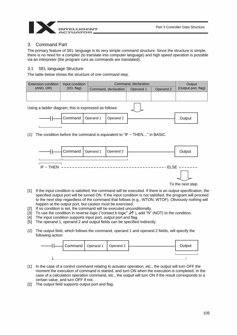
105
Part 3 Controller Data Structure
3. Command Part The primary feature of SEL language is its very simple command structure. Since the structure is simple, there is no need for a compiler (to translate into computer language) and high speed operation is possible via an interpreter (the program runs as commands are translated). 3.1 SEL language Structure The table below shows the structure of one command step.
Command, declaration Extension condition (AND, OR)
Input condition (I/O, flag) Command, declaration Operand 1 Operand 2
Output (Output port, flag)
Using a ladder diagram, this is expressed as follows: (1) The condition before the command is equivalent to “IF ~ THEN…” in BASIC. [1] If the input condition is satisfied, the command will be executed. If there is an output specification, the
specified output port will be turned ON. If the input condition is not satisfied, the program will proceed to the next step regardless of the command that follows (e.g., WTON, WTOF). Obviously nothing will happen at the output port, but caution must be exercised.
[2] If no condition is set, the command will be executed unconditionally. [3] To use the condition in reverse logic (“contact b logic” ), add "N" (NOT) to the condition. [4] The input condition supports input port, output port and flag. [5] The operand 1, operand 2 and output fields can be specified indirectly. (2) The output field, which follows the command, operand 1 and operand 2 fields, will specify the
following action: [1] In the case of a control command relating to actuator operation, etc., the output will turn OFF the
moment the execution of command is started, and turn ON when the execution is completed. In the case of a calculation operation command, etc., the output will turn ON if the result corresponds to a certain value, and turn OFF if not.
[2] The output field supports output port and flag.
To the next step
Command Operand 1 Operand 2 Output
Command Operand 1 Operand 2 Output
IF ~ THEN ELSE
↓
Command Operand 1 Operand 2 Output
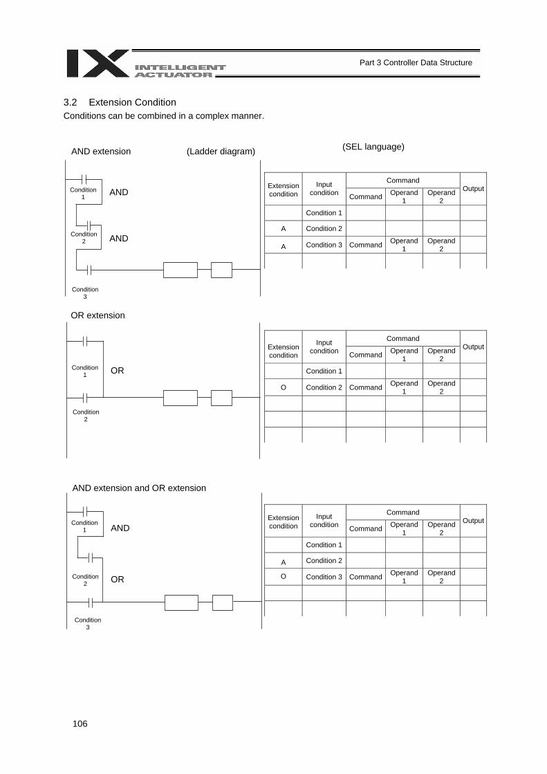
106
Part 3 Controller Data Structure
Condition 1
Condition 2
Condition 1
Condition 2
Condition 1
Condition 2
Condition 3
3.2 Extension Condition Conditions can be combined in a complex manner.
(SEL language)
Command Extension condition
Input condition Command Operand
1 Operand
2
Output
Condition 1
A Condition 2
A Condition 3 Command Operand 1
Operand 2
Command Extension condition
Input condition Command Operand
1 Operand
2
Output
Condition 1
O Condition 2 Command Operand 1
Operand 2
Command Extension condition
Input condition Command Operand
1 Operand
2
Output
Condition 1
A Condition 2
O Condition 3 Command Operand 1
Operand 2
AND extension (Ladder diagram)
Condition 3
OR extension
AND extension and OR extension
AND
AND
AND OR
OR
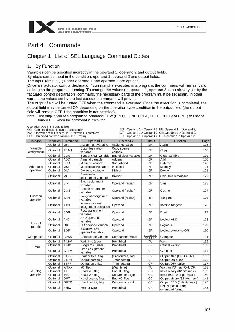
107
Part 4 Commands
Part 4 Commands Chapter 1 List of SEL Language Command Codes 1. By Function Variables can be specified indirectly in the operand 1, operand 2 and output fields. Symbols can be input in the condition, operand 1, operand 2 and output fields. The input items in ( ) under operand 1 and operand 2 are optional. Once an “actuator control declaration” command is executed in a program, the command will remain valid as long as the program is running. To change the values (in operand 1, operand 2, etc.) already set by the “actuator control declaration” command, the necessary parts of the program must be set again. In other words, the values set by the last executed command will prevail. The output field will be turned OFF when the command is executed. Once the execution is completed, the output field may be turned ON depending on the operation type condition in the output field (the output field will remain OFF if the condition is not satisfied). Note: The output field of a comparison command CPxx (CPEQ, CPNE, CPGT, CPGE, CPLT and CPLE) will not be
turned OFF when the command is executed. Operation type in the output field CC: Command was executed successfully, ZR: Operation result is zero, PE: Operation is complete, CP: Command part has passed, TU: Time up
EQ: Operand 1 = Operand 2, NE: Operand 1 ≠ Operand 2, GT: Operand 1 > Operand 2, GE: Operand 1 ≥ Operand 2, LT: Operand 1 < Operand 2, LE: Operand 1 ≤ Operand 2
Category Condition Command Operand 1 Operand 2 Output Function PageOptional LET Assignment variable Assigned value ZR Assign 118
Optional TRAN Copy destination variable
Copy source variable ZR Copy 118 Variable
assignment Optional CLR Start of clear variable End of clear variable ZR Clear variable 119 Optional ADD Augend variable Addend ZR Add 120 Optional SUB Minuend variable Subtrahend ZR Subtract 120 Optional MULT Multiplicand variable Multiplier ZR Multiply 121 Optional DIV Dividend variable Divisor ZR Divide 121
Arithmetic operation
Optional MOD Remainder assignment variable Divisor ZR Calculate remainder 122
Optional SIN Sine assignment variable Operand [radian] ZR Sine 123
Optional COS Cosine assignment variable Operand [radian] ZR Cosine 124
Optional TAN Tangent assignment variable Operand [radian] ZR Tangent 125
Optional ATN Inverse-tangent assignment operation Operand ZR Inverse tangent 126
Function operation
Optional SQR Root assignment variable Operand ZR Root 127
Optional AND AND operand variable Operand ZR Logical AND 128
Optional OR OR operand variable Operand ZR Logical OR 129 Logical operation
Optional EOR Exclusive OR operand variable Operand ZR Logical exclusive OR 130
Comparison Optional CPXX Comparison variable Comparison value EQ, NE, GT, GE, LT, LE Compare 131
Optional TIMW Wait time (sec) Prohibited TU Wait 132 Optional TIMC Program number Prohibited CP Cancel waiting 133 Timer Optional GTTM Time assignment
variable Prohibited CP Get time 134
Optional BTXX Start output, flag (End output, flag) CP Output, flag [ON, OF, NT] 135 Optional BTPN Output port, flag Timer setting CP Output ON pulse 136 Optional BTPF Output port, flag Timer setting CP Output OFF pulse 137 Optional WTXX I/O, flag (Wait time) TU Wait for I/O, flag [ON, OF] 138 Optional IN Head I/O, flag End I/O, flag CC Input binary (32 bits max.) 139 Optional INB Head I/O, flag Conversion digits CC Input BCD (8 digits max.) 140 Optional OUT Head output, flag End I/O, flag CC Output binary (32 bits max.) 141 Optional OUTB Head output, flag Conversion digits CC Output BCD (8 digits max.) 142
I/O, flag operation
Optional FMIO Format type Prohibited CP Set IN (B)/OUT (B) command format 143
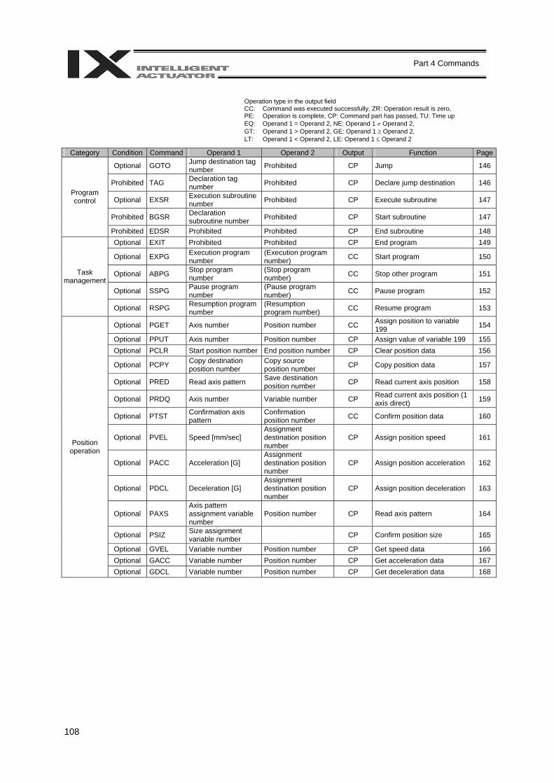
108
Part 4 Commands
Operation type in the output field CC: Command was executed successfully, ZR: Operation result is zero, PE: Operation is complete, CP: Command part has passed, TU: Time up EQ: Operand 1 = Operand 2, NE: Operand 1 ≠ Operand 2, GT: Operand 1 > Operand 2, GE: Operand 1 ≥ Operand 2, LT: Operand 1 < Operand 2, LE: Operand 1 ≤ Operand 2
Category Condition Command Operand 1 Operand 2 Output Function Page
Optional GOTO Jump destination tag number Prohibited CP Jump 146
Prohibited TAG Declaration tag number Prohibited CP Declare jump destination 146
Optional EXSR Execution subroutine number Prohibited CP Execute subroutine 147
Prohibited BGSR Declaration subroutine number Prohibited CP Start subroutine 147
Program control
Prohibited EDSR Prohibited Prohibited CP End subroutine 148 Optional EXIT Prohibited Prohibited CP End program 149
Optional EXPG Execution program number
(Execution program number) CC Start program 150
Optional ABPG Stop program number
(Stop program number) CC Stop other program 151
Optional SSPG Pause program number
(Pause program number) CC Pause program 152
Task management
Optional RSPG Resumption program number
(Resumption program number) CC Resume program 153
Optional PGET Axis number Position number CC Assign position to variable 199 154
Optional PPUT Axis number Position number CP Assign value of variable 199 155 Optional PCLR Start position number End position number CP Clear position data 156
Optional PCPY Copy destination position number
Copy source position number CP Copy position data 157
Optional PRED Read axis pattern Save destination position number CP Read current axis position 158
Optional PRDQ Axis number Variable number CP Read current axis position (1 axis direct) 159
Optional PTST Confirmation axis pattern
Confirmation position number CC Confirm position data 160
Optional PVEL Speed [mm/sec] Assignment destination position number
CP Assign position speed 161
Optional PACC Acceleration [G] Assignment destination position number
CP Assign position acceleration 162
Optional PDCL Deceleration [G] Assignment destination position number
CP Assign position deceleration 163
Optional PAXS Axis pattern assignment variable number
Position number CP Read axis pattern 164
Optional PSIZ Size assignment variable number CP Confirm position size 165
Optional GVEL Variable number Position number CP Get speed data 166 Optional GACC Variable number Position number CP Get acceleration data 167
Position operation
Optional GDCL Variable number Position number CP Get deceleration data 168

109
Part 4 Commands
Operation type in the output field CC: Command was executed successfully, ZR: Operation result is zero, PE: Operation is complete, CP: Command part has passed, TU: Time up EQ: Operand 1 = Operand 2, NE: Operand 1 ≠ Operand 2, GT: Operand 1 > Operand 2, GE: Operand 1 ≥ Operand 2, LT: Operand 1 < Operand 2, LE: Operand 1 ≤ Operand 2
Category Condition Command Operand 1 Operand 2 Output Function PageOptional VEL Speed [mm/sec] Prohibited CP Set speed 169
Optional VELS Ratio [%] Prohibited CP Set speed ratio for PTP operation (SCARA only) 170
Optional OVRD Speed ratio [%] Prohibited CP Set speed coefficient 171 Optional ACC Acceleration [G] Prohibited CP Set acceleration 172
Optional ACCS Ratio [%] Prohibited CP Set acceleration ratio for PTP operation (SCARA only) 173
Optional DCL Deceleration [G] Prohibited CP Set deceleration 174
Optional DCLS Ratio [%] Prohibited CP Set deceleration ratio for PTP operation (SCARA only) 175
Optional VLMX Prohibited Prohibited CP Specify VLMX speed (Linear movement axis only) 176
Optional SCRV Ratio [%] Prohibited CP Set sigmoid motion ratio 177 Optional OFST Setting axis pattern Offset value [mm] CP Set offset 178 Optional DEG Division angle [deg] Prohibited CP Set division angle 179
Optional BASE Reference axis number Prohibited CP Set reference axis 180
Optional GRP Valid axis pattern Prohibited CP Set group axes 181 Optional HOLD (Input port to pause) (HOLD type) CP Declare port to pause 182 Optional CANC (Input port to abort) (CANC type) CP Declare port to abort 183 Optional DIS Distance Prohibited CP Set spline division distance 184 Optional POTP 0 or 1 Prohibited CP Set PATH output type 185 Optional PAPR Distance Speed CP Set PUSH command distance, speed 186
Optional DFTL Tool coordinate system number Position number CP Define tool coordinate system (SCARA
only) 187
Optional SLTL Tool coordinate system number Prohibited CP Select tool coordinate system (SCARA
only) 188
Optional GTTL Tool coordinate system number Position number CP Get tool coordinate system definition
data (SCARA only) 189
Optional DFWK Work coordinate system number Position number CP Define work coordinate system (SCARA
only) 190
Optional SLWK Work coordinate system number Prohibited CP Select work coordinate system (SCARA
only) 191
Optional GTWK Work coordinate system number Position number CP Get work coordinate system definition data
(SCARA only) 192
Optional RIGH Prohibited Prohibited PE Change current arm system to right arm (Arm 2 may operate if the current arm system is the opposite arm) (SCARA only)
193
Optional LEFT Prohibited Prohibited PE Change current arm system to left arm (Arm 2 may operate if the current arm system is the opposite arm) (SCARA only)
194
Optional PTPR Prohibited Prohibited CP
Specify right arm as PTP target arm system (Movement of the opposite arm system is prohibited when the target value cannot be achieved) (No arm operation) (SCARA only)
195
Optional PTPL Prohibited Prohibited CP
Specify left arm as PTP target arm system (Movement of the opposite arm system is prohibited when the target value cannot be achieved) (No arm operation) (SCARA only)
196
Optional PTPD Prohibited Prohibited CP
Specify current arm as PTP target arm system (Movement of the opposite arm system is prohibited when the target value cannot be achieved) (No arm operation) (SCARA only)
197
Optional PTPE Prohibited Prohibited CP
Specify current arm as PTP target arm system (Movement of the opposite arm system is permitted when the target value cannot be achieved) (No arm operation) (SCARA only)
198
Optional DFIF Interference check zone number Position number CP Define coordinates of simple interference
check zone (SCARA only) 199
Optional SOIF Interference check zone number
Output/global flag number CP Specify output for simple interference
check zone (SCARA only) 200
Optional SEIF Interference check zone number
0 or 1 or 2 (Error type) CP Specify error type for simple interference
check zone (SCARA only) 201
Actuator control
declaration
Optional GTIF Interference check zone number Position number CP Get definition coordinates of simple
interference check zone (SCARA only) 202
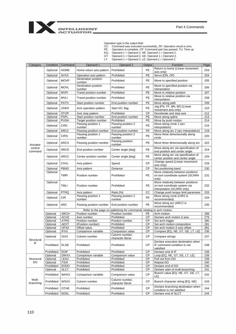
110
Part 4 Commands
Operation type in the output field CC: Command was executed successfully, ZR: Operation result is zero, PE: Operation is complete, CP: Command part has passed, TU: Time up EQ: Operand 1 = Operand 2, NE: Operand 1 ≠ Operand 2, GT: Operand 1 > Operand 2, GE: Operand 1 ≥ Operand 2, LT: Operand 1 < Operand 2, LE: Operand 1 ≤ Operand 2
Category Condition Command Operand 1 Operand 2 Output Function Page
Optional HOME Home-return axis pattern Prohibited PE Return to home (Linear movement axis only) 203
Optional SVXX Operation axis pattern Prohibited PE Servo [ON, OF] 204
Optional MOVP Destination position number Prohibited PE Move to specified position 205
Optional MOVL Destination position number Prohibited PE Move to specified position via
interpolation 206
Optional MVPI Travel position number Prohibited PE Move to relative position 207
Optional MVLI Travel position number Prohibited PE Move to relative position via interpolation 208
Optional PATH Start position number End position number PE Move along path 209
Optional JXWX Axis operation pattern Start I/O, flag PE Jog [FN, FF, BN, BF] (Linear movement axis only) 210
Optional STOP Axis stop pattern Prohibited CP Decelerate and stop axis 212 Optional PSPL Start position number End position number PE Move along spline 213 Optional PUSH Target position number Prohibited PE Move by push motion 214
Optional CIR2 Passing position 1 number
Passing position 2 number PE Move along circle 2 (arc
interpolation) 216
Optional ARC2 Passing position number End position number PE Move along arc 2 (arc interpolation) 218
Optional CIRS Passing position 1 number
Passing position 2 number PE Move three dimensionally along
circle 220
Optional ARCS Passing position number Passing position number PE Move three dimensionally along arc 222
Optional ARCD End position number Center angle [deg] PE Move along arc via specification of end position and center angle 224
Optional ARCC Center position number Center angle [deg] PE Move along arc via specification of center position and center angle 226
Optional CHVL Axis pattern Speed CP Change speed (Linear movement axis only) 228
Optional PBND Axis pattern Distance CP Set positioning band 230 Optional
TMPI Position number Prohibited PE Move relatively between positions on tool coordinate system (SCARA only)
231
Optional TMLI Position number Prohibited PE
Move relatively between positions on tool coordinate system via interpolation (SCARA only)
232
Optional PTRQ Axis pattern Ratio [%] CC Change push torque limit parameter 233
Optional CIR Passing position 1 number
Passing position 2 number PE Move along circle (CIR2 is
recommended) 234
Optional ARC Passing position number End position number PE Move along arc (ARC2 is recommended) 235
Refer to the page on palletizing for commands relating to arch motion. Optional ARCH Position number Position number PE Arch motion 289 Optional ACHZ Axis number Prohibited CP Declare arch motion Z-axis 279 Optional ATRG Position number Position number CP Set arch trigger 280 Optional AEXT (Position number) Prohibited CP Set arch motion composition 281
Actuator control
command
Optional OFAZ Offset value Prohibited CP Set arch motion Z-axis offset 281 Optional IFXX Comparison variable Comparison value CP Compare [EQ, NE, GT, GE, LT, LE] 236
Optional ISXX Column number Column number, character literal CP Compare strings 237
Prohibited ELSE Prohibited Prohibited CP Declare execution destination when IF command condition is not satisfied
238
Structural IF
Prohibited EDIF Prohibited Prohibited CP Declare end of IF 238 Optional DWXX Comparison variable Comparison value CP Loop [EQ, NE, GT, GE, LT, LE] 239 Optional LEAV Prohibited Prohibited CP Pull out from DO 239 Optional ITER Prohibited Prohibited CP Repeat DO 240
Structural DO
Prohibited EDDO Prohibited Prohibited CP Declare end of DO 240 Optional SLCT Prohibited Prohibited CP Declare start of multi-branching 241
Prohibited WHXX Comparison variable Comparison value CP Branch value [EQ, NE, GT, GE, LT, LE] 242
Prohibited WSXX Column number Column number, character literal CP Branch character string [EQ, NE] 243
Prohibited OTHE Prohibited Prohibited CP Declare branching destination when condition is not satisfied 244
Multi-branching
Prohibited EDSL Prohibited Prohibited CP Declare end of SLCT 244
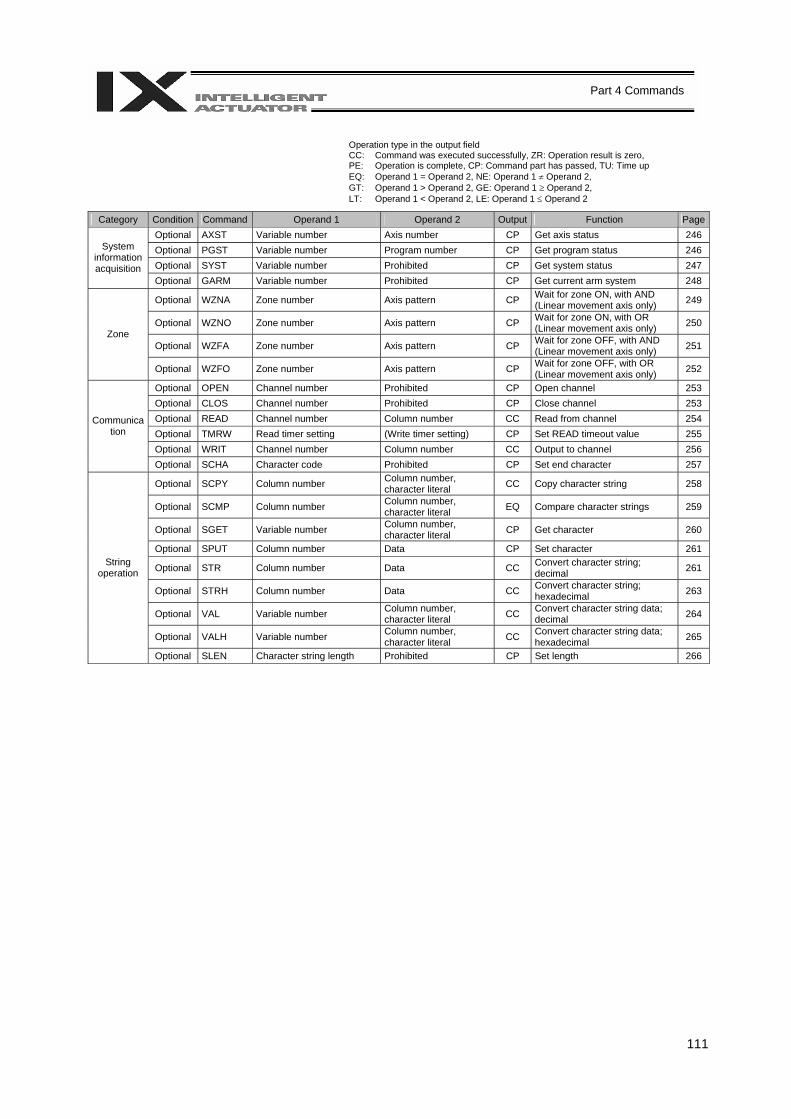
111
Part 4 Commands
Operation type in the output field CC: Command was executed successfully, ZR: Operation result is zero, PE: Operation is complete, CP: Command part has passed, TU: Time up EQ: Operand 1 = Operand 2, NE: Operand 1 ≠ Operand 2, GT: Operand 1 > Operand 2, GE: Operand 1 ≥ Operand 2, LT: Operand 1 < Operand 2, LE: Operand 1 ≤ Operand 2
Category Condition Command Operand 1 Operand 2 Output Function PageOptional AXST Variable number Axis number CP Get axis status 246 Optional PGST Variable number Program number CP Get program status 246 Optional SYST Variable number Prohibited CP Get system status 247
System information acquisition
Optional GARM Variable number Prohibited CP Get current arm system 248
Optional WZNA Zone number Axis pattern CP Wait for zone ON, with AND (Linear movement axis only) 249
Optional WZNO Zone number Axis pattern CP Wait for zone ON, with OR (Linear movement axis only) 250
Optional WZFA Zone number Axis pattern CP Wait for zone OFF, with AND (Linear movement axis only) 251
Zone
Optional WZFO Zone number Axis pattern CP Wait for zone OFF, with OR (Linear movement axis only) 252
Optional OPEN Channel number Prohibited CP Open channel 253 Optional CLOS Channel number Prohibited CP Close channel 253 Optional READ Channel number Column number CC Read from channel 254 Optional TMRW Read timer setting (Write timer setting) CP Set READ timeout value 255 Optional WRIT Channel number Column number CC Output to channel 256
Communication
Optional SCHA Character code Prohibited CP Set end character 257
Optional SCPY Column number Column number, character literal CC Copy character string 258
Optional SCMP Column number Column number, character literal EQ Compare character strings 259
Optional SGET Variable number Column number, character literal CP Get character 260
Optional SPUT Column number Data CP Set character 261
Optional STR Column number Data CC Convert character string; decimal 261
Optional STRH Column number Data CC Convert character string; hexadecimal 263
Optional VAL Variable number Column number, character literal CC Convert character string data;
decimal 264
Optional VALH Variable number Column number, character literal CC Convert character string data;
hexadecimal 265
String operation
Optional SLEN Character string length Prohibited CP Set length 266
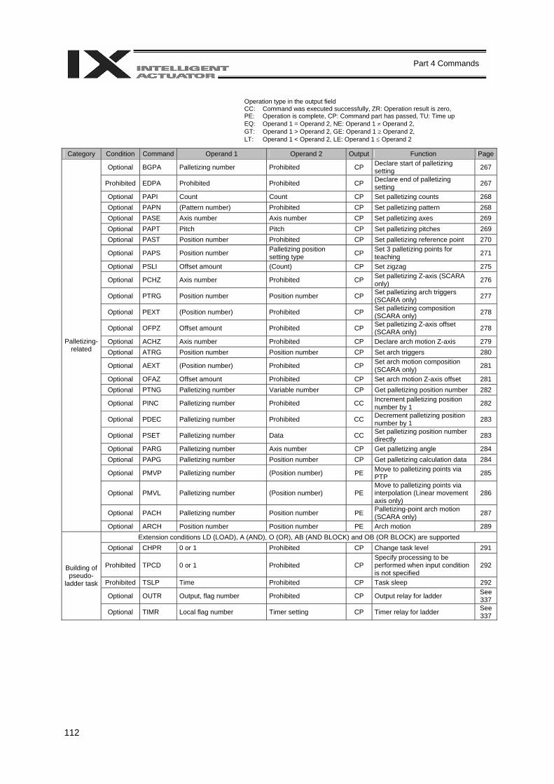
112
Part 4 Commands
Operation type in the output field CC: Command was executed successfully, ZR: Operation result is zero, PE: Operation is complete, CP: Command part has passed, TU: Time up EQ: Operand 1 = Operand 2, NE: Operand 1 ≠ Operand 2, GT: Operand 1 > Operand 2, GE: Operand 1 ≥ Operand 2, LT: Operand 1 < Operand 2, LE: Operand 1 ≤ Operand 2
Category Condition Command Operand 1 Operand 2 Output Function Page
Optional BGPA Palletizing number Prohibited CP Declare start of palletizing setting 267
Prohibited EDPA Prohibited Prohibited CP Declare end of palletizing setting 267
Optional PAPI Count Count CP Set palletizing counts 268 Optional PAPN (Pattern number) Prohibited CP Set palletizing pattern 268 Optional PASE Axis number Axis number CP Set palletizing axes 269 Optional PAPT Pitch Pitch CP Set palletizing pitches 269 Optional PAST Position number Prohibited CP Set palletizing reference point 270
Optional PAPS Position number Palletizing position setting type CP Set 3 palletizing points for
teaching 271
Optional PSLI Offset amount (Count) CP Set zigzag 275
Optional PCHZ Axis number Prohibited CP Set palletizing Z-axis (SCARA only) 276
Optional PTRG Position number Position number CP Set palletizing arch triggers (SCARA only) 277
Optional PEXT (Position number) Prohibited CP Set palletizing composition (SCARA only) 278
Optional OFPZ Offset amount Prohibited CP Set palletizing Z-axis offset (SCARA only) 278
Optional ACHZ Axis number Prohibited CP Declare arch motion Z-axis 279 Optional ATRG Position number Position number CP Set arch triggers 280
Optional AEXT (Position number) Prohibited CP Set arch motion composition (SCARA only) 281
Optional OFAZ Offset amount Prohibited CP Set arch motion Z-axis offset 281 Optional PTNG Palletizing number Variable number CP Get palletizing position number 282
Optional PINC Palletizing number Prohibited CC Increment palletizing position number by 1 282
Optional PDEC Palletizing number Prohibited CC Decrement palletizing position number by 1 283
Optional PSET Palletizing number Data CC Set palletizing position number directly 283
Optional PARG Palletizing number Axis number CP Get palletizing angle 284 Optional PAPG Palletizing number Position number CP Get palletizing calculation data 284
Optional PMVP Palletizing number (Position number) PE Move to palletizing points via PTP 285
Optional PMVL Palletizing number (Position number) PE Move to palletizing points via interpolation (Linear movement axis only)
286
Optional PACH Palletizing number Position number PE Palletizing-point arch motion (SCARA only) 287
Palletizing-related
Optional ARCH Position number Position number PE Arch motion 289 Extension conditions LD (LOAD), A (AND), O (OR), AB (AND BLOCK) and OB (OR BLOCK) are supported
Optional CHPR 0 or 1 Prohibited CP Change task level 291
Prohibited TPCD 0 or 1 Prohibited CP Specify processing to be performed when input condition is not specified
292
Prohibited TSLP Time Prohibited CP Task sleep 292
Optional OUTR Output, flag number Prohibited CP Output relay for ladder See 337
Building of pseudo-
ladder task
Optional TIMR Local flag number Timer setting CP Timer relay for ladder See 337
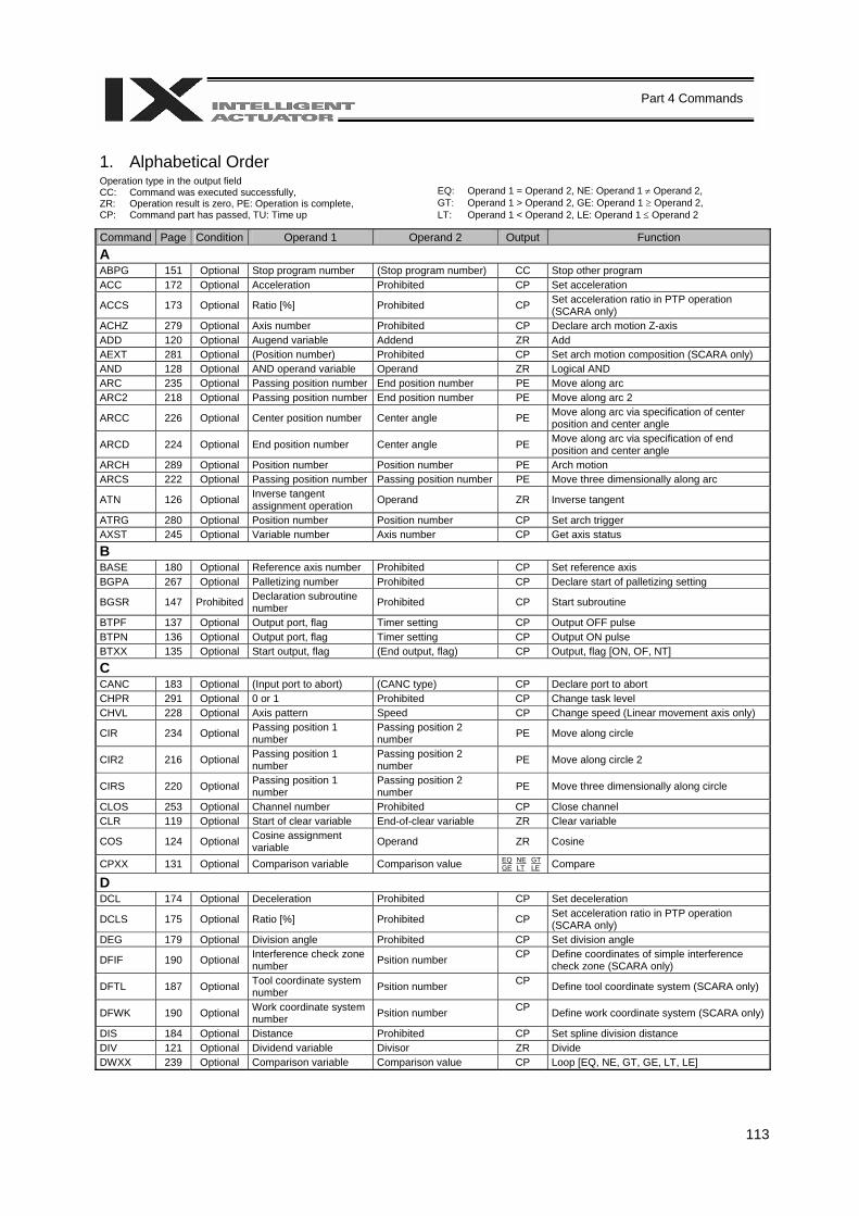
113
Part 4 Commands
1. Alphabetical Order Operation type in the output field CC: Command was executed successfully, ZR: Operation result is zero, PE: Operation is complete, CP: Command part has passed, TU: Time up
EQ: Operand 1 = Operand 2, NE: Operand 1 ≠ Operand 2, GT: Operand 1 > Operand 2, GE: Operand 1 ≥ Operand 2, LT: Operand 1 < Operand 2, LE: Operand 1 ≤ Operand 2
Command Page Condition Operand 1 Operand 2 Output Function A ABPG 151 Optional Stop program number (Stop program number) CC Stop other program ACC 172 Optional Acceleration Prohibited CP Set acceleration
ACCS 173 Optional Ratio [%] Prohibited CP Set acceleration ratio in PTP operation (SCARA only)
ACHZ 279 Optional Axis number Prohibited CP Declare arch motion Z-axis ADD 120 Optional Augend variable Addend ZR Add AEXT 281 Optional (Position number) Prohibited CP Set arch motion composition (SCARA only) AND 128 Optional AND operand variable Operand ZR Logical AND ARC 235 Optional Passing position number End position number PE Move along arc ARC2 218 Optional Passing position number End position number PE Move along arc 2
ARCC 226 Optional Center position number Center angle PE Move along arc via specification of center position and center angle
ARCD 224 Optional End position number Center angle PE Move along arc via specification of end position and center angle
ARCH 289 Optional Position number Position number PE Arch motion ARCS 222 Optional Passing position number Passing position number PE Move three dimensionally along arc
ATN 126 Optional Inverse tangent assignment operation Operand ZR Inverse tangent
ATRG 280 Optional Position number Position number CP Set arch trigger AXST 245 Optional Variable number Axis number CP Get axis status
B BASE 180 Optional Reference axis number Prohibited CP Set reference axis BGPA 267 Optional Palletizing number Prohibited CP Declare start of palletizing setting
BGSR 147 Prohibited Declaration subroutine number Prohibited CP Start subroutine
BTPF 137 Optional Output port, flag Timer setting CP Output OFF pulse BTPN 136 Optional Output port, flag Timer setting CP Output ON pulse BTXX 135 Optional Start output, flag (End output, flag) CP Output, flag [ON, OF, NT]
C CANC 183 Optional (Input port to abort) (CANC type) CP Declare port to abort CHPR 291 Optional 0 or 1 Prohibited CP Change task level CHVL 228 Optional Axis pattern Speed CP Change speed (Linear movement axis only)
CIR 234 Optional Passing position 1 number
Passing position 2 number PE Move along circle
CIR2 216 Optional Passing position 1 number
Passing position 2 number PE Move along circle 2
CIRS 220 Optional Passing position 1 number
Passing position 2 number PE Move three dimensionally along circle
CLOS 253 Optional Channel number Prohibited CP Close channel CLR 119 Optional Start of clear variable End-of-clear variable ZR Clear variable
COS 124 Optional Cosine assignment variable Operand ZR Cosine
CPXX 131 Optional Comparison variable Comparison value EQ NE GT GE LT LE Compare
D DCL 174 Optional Deceleration Prohibited CP Set deceleration
DCLS 175 Optional Ratio [%] Prohibited CP Set acceleration ratio in PTP operation (SCARA only)
DEG 179 Optional Division angle Prohibited CP Set division angle
DFIF 190 Optional Interference check zone number Psition number CP Define coordinates of simple interference
check zone (SCARA only)
DFTL 187 Optional Tool coordinate system number Psition number CP Define tool coordinate system (SCARA only)
DFWK 190 Optional Work coordinate system number Psition number CP Define work coordinate system (SCARA only)
DIS 184 Optional Distance Prohibited CP Set spline division distance DIV 121 Optional Dividend variable Divisor ZR Divide DWXX 239 Optional Comparison variable Comparison value CP Loop [EQ, NE, GT, GE, LT, LE]
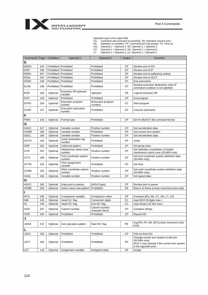
114
Part 4 Commands
Operation type in the output field CC: Command was executed successfully, ZR: Operation result is zero, PE: Operation is complete, CP: Command part has passed, TU: Time up EQ: Operand 1 = Operand 2, NE: Operand 1 ≠ Operand 2, GT: Operand 1 > Operand 2, GE: Operand 1 ≥ Operand 2, LT: Operand 1 < Operand 2, LE: Operand 1 ≤ Operand 2
Command Page Condition Operand 1 Operand 2 Output Function
E EDDO 240 Prohibited Prohibited Prohibited CP Declare end of DO EDIF 238 Prohibited Prohibited Prohibited CP Declare end of IF EDPA 267 Prohibited Prohibited Prohibited CP Declare end of palletizing setting EDSL 244 Prohibited Prohibited Prohibited CP Declare end of SLCT EDSR 148 Prohibited Prohibited Prohibited CP End subroutine
ELSE 238 Prohibited Prohibited Prohibited CP Declare execution destination when IF command condition is not satisfied
EOR 130 Optional Exclusive OR operand variable Operand ZR Logical exclusive OR
EXIT 149 Optional Prohibited Prohibited CP End program
EXPG 150 Optional Execution program number
(Execution program number) CC Start program
EXSR 147 Optional Execution subroutine number Prohibited CP Execute subroutine
F FMIO 143 Optional Format type Prohibited CP Set IN (B)/OUT (B) command format
G GACC 157 Optional Variable number Position number CP Get acceleration data GARM 248 Optional Variable number Prohibited CP Get current arm system GDCL 168 Optional Variable number Position number CP Get deceleration data
GOTO 146 Optional Jump destination tag number Prohibited CP Jump
GRP 181 Optional Valid axis pattern Prohibited CP Set group axes
GTIF 202 Optional Interference check zone number Position number CP Get definition coordinates of simple
interference check zone (SCARA only)
GTTL 189 Optional Tool coordinate system number Position number CP Get tool coordinate system definition data
(SCARA only)
GTTM 134 Optional Time assignment variable Prohibited CP Get time
GTWK 192 Optional Work coordinate system number Position number CP Get work coordinate system definition data
(SCARA only) GVEL 166 Optional Variable number Position number CP Get speed data
H HOLD 182 Optional (Input port to pause) (HOLD type) CP Declare port to pause HOME 203 Optional Home return axis pattern Prohibited PE Return to home (Linear movement axis only)
I IFXX 236 Optional Comparison variable Comparison value CP Compare [EQ, NE, GT, GE, LT, LE] INB 140 Optional Head I/O, flag Conversion digits CC Input BCD (8 digits max.) IN 139 Optional Head I/O, flag End I/O, flag CC Input binary (32 bits max.)
ISXX 237 Optional Column number Column number, character literal CP Compare strings
ITER 240 Optional Prohibited Prohibited CP Repeat DO
J JXWX 210 Optional Axis operation pattern Start I/O, flag PE Jog [FN, FF, BN, BF] (Linear movement axis
only)
L LEAV 239 Optional Prohibited Prohibited CP Pull out from DO
LEFT 194 Optional Prohibited Prohibited PE
Change current arm system to left arm (SCARA only) (Arm 2 may operate if the current arm system is the opposite arm)
LET 118 Optional Assignment variable Assigned value ZR Assign
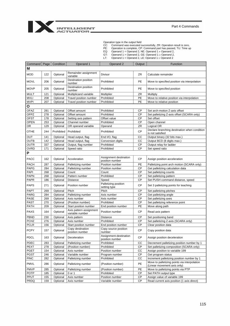
115
Part 4 Commands
Operation type in the output field CC: Command was executed successfully, ZR: Operation result is zero, PE: Operation is complete, CP: Command part has passed, TU: Time up EQ: Operand 1 = Operand 2, NE: Operand 1 ≠ Operand 2, GT: Operand 1 > Operand 2, GE: Operand 1 ≥ Operand 2, LT: Operand 1 < Operand 2, LE: Operand 1 ≤ Operand 2
Command Page Condition Operand 1 Operand 2 Output Function M MOD 122 Optional Remainder assignment
variable Divisor ZR Calculate remainder
MOVL 206 Optional Destination position number Prohibited PE Move to specified position via interpolation
MOVP 205 Optional Destination position number Prohibited PE Move to specified position
MULT 121 Optional Multiplicand variable Multiplier ZR Multiply MVLI 208 Optional Travel position number Prohibited PE Move to relative position via interpolation MVPI 207 Optional Travel position number Prohibited PE Move to relative position
O OFAZ 281 Optional Offset amount Prohibited CP Set arch-motion Z-axis offset OFPZ 278 Optional Offset amount Prohibited CP Set palletizing Z-axis offset (SCARA only) OFST 178 Optional Setting axis pattern Offset value CP Set offset OPEN 253 Optional Channel number Prohibited CP Open channel OR 129 Optional OR operand variable Operand ZR Logical OR
OTHE 244 Prohibited Prohibited Prohibited CP Declare branching destination when condition is not satisfied
OUT 141 Optional Head output, flag End I/O, flag CC Output binary (32 bits max.) OUTB 142 Optional Head output, flag Conversion digits CC Output BCD (8 digits max.) OUTR 337 Optional Output, flag number Prohibited CP Output relay for ladder OVRD 171 Optional Speed ratio Prohibited CP Set speed ratio
P PACC 162 Optional Acceleration Assignment destination
position number CP Assign position acceleration
PACH 287 Optional Palletizing number Position number PE Palletizing point arch motion (SCARA only) PAPG 284 Optional Palletizing number Position number CP Get palletizing calculation data PAPI 268 Optional Count Count CP Set palletizing counts PAPN 268 Optional Pattern number Prohibited CP Set palletizing pattern PAPR 186 Optional Distance Speed CP Set PUSH command distance, speed
PAPS 271 Optional Position number Palletizing position setting type CP Set 3 palletizing points for teaching
PAPT 269 Optional Pitch Pitch CP Set palletizing pitches PARG 284 Optional Palletizing number Axis number CP Get palletizing angle PASE 269 Optional Axis number Axis number CP Set palletizing axes PAST 270 Optional (Position number) Prohibited CP Set palletizing reference point PATH 209 Optional Start position number End position number PE Move along path
PAXS 164 Optional Axis pattern assignment variable number Position number CP Read axis pattern
PBND 230 Optional Axis pattern Distance CP Set positioning band PCHZ 276 Optional Axis number Prohibited CP Set palletizing Z-axis (SCARA only) PCLR 156 Optional Start position number End position number CP Clear position data
PCPY 157 Optional Copy destination position number
Copy source position number CP Copy position data
PDCL 163 Optional Deceleration Assignment-destination position number CP Assign position deceleration
PDEC 283 Optional Palletizing number Prohibited CC Decrement palletizing position number by 1 PEXT 278 Optional (Position number) Prohibited CP Set palletizing composition (SCARA only) PGET 154 Optional Axis number Position number CC Assign position to variable 199 PGST 246 Optional Variable number Program number CP Get program status PINC 282 Optional Palletizing number Prohibited CC Increment palletizing position number by 1
PMVL 286 Optional Palletizing number (Position number) PE Move to palletizing points via interpolation (Linear movement axis only)
PMVP 285 Optional Palletizing number (Position number) PE Move to palletizing points via PTP POTP 185 Optional 0 or 1 Prohibited CP Set PATH output type PPUT 155 Optional Axis number Position number CP Assign value of variable 199 PRDQ 159 Optional Axis number Variable number CP Read current axis position (1 axis direct)
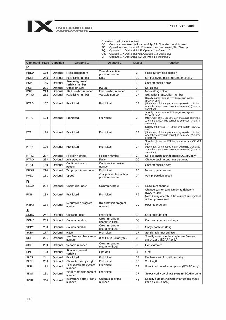
116
Part 4 Commands
Operation type in the output field CC: Command was executed successfully, ZR: Operation result is zero, PE: Operation is complete, CP: Command part has passed, TU: Time up EQ: Operand 1 = Operand 2, NE: Operand 1 ≠ Operand 2, GT: Operand 1 > Operand 2, GE: Operand 1 ≥ Operand 2, LT: Operand 1 < Operand 2, LE: Operand 1 ≤ Operand 2
Command Page Condition Operand 1 Operand 2 Output Function P PRED 158 Optional Read axis pattern Save destination
position number CP Read current axis position
PSET 283 Optional Palletizing number Data CC Set palletizing position number directly
PSIZ 165 Optional Size assignment variable number CP Confirm position size
PSLI 275 Optional Offset amount (Count) CP Set zigzag PSPL 213 Optional Start position number End position number PE Move along spline PTNG 282 Optional Palletizing number Variable number CP Get palletizing position number
PTPD 197 Optional Prohibited Prohibited CP Specify current arm as PTP target arm system (SCARA only) (Movement of the opposite arm system is prohibited when the target value cannot be achieved) (No arm operation)
PTPE 198 Optional Prohibited Prohibited CP Specify current arm as PTP target arm system (SCARA only) (Movement of the opposite arm system is permitted when the target value cannot be achieved) (No arm operation)
PTPL 196 Optional Prohibited Prohibited CP Specify left arm as PTP target arm system (SCARA only) (Movement of the opposite arm system is prohibited when the target value cannot be achieved) (No arm operation)
PTPR 195 Optional Prohibited Prohibited CP Specify right arm as PTP target arm system (SCARA only) (Movement of the opposite arm system is prohibited when the target value cannot be achieved) (No arm operation)
PTRG 277 Optional Position number Position number CP Set palletizing arch triggers (SCARA only) PTRQ 233 Optional Axis pattern Ratio CC Change push torque limit parameter
PTST 160 Optional Confirmation axis pattern
Confirmation position number CP Confirm position data
PUSH 214 Optional Target position number Prohibited PE Move by push motion
PVEL 161 Optional Speed Assignment destination position number CP Assign position speed
R READ 254 Optional Channel number Column number CC Read from channel
RIGH 193 Optional Prohibited Prohibited PE
Change current arm system to right arm (SCARA only) (Arm 2 may operate if the current arm system is the opposite arm)
RSPG 153 Optional Resumption program number
(Resumption program number) CC Resume program
S SCHA 257 Optional Character code Prohibited CP Set end character
SCMP 259 Optional Column number Column number, character literal EQ Compare character strings
SCPY 258 Optional Column number Column number, character literal CC Copy character string
SCRV 177 Optional Ratio Prohibited CP Set sigmoid motion ratio
SEIF 201 Optional Interference check zone number 0 or 1 or 2 (Error type) CP Specify error type for simple interference
check zone (SCARA only)
SGET 260 Optional Variable number Column number, character literal CP Get character
SIN 123 Optional Sine assignment variable Operand ZR Sine
SLCT 241 Optional Prohibited Prohibited CP Declare start of multi-branching SLEN 266 Optional Character string length Prohibited CP Set length
SLTL 188 Optional Tool coordinate system number
Prohibited CP Select tool coordinate system (SCARA only)
SLWK 191 Optional Work coordinate system number
Prohibited CP Select work coordinate system (SCARA only)
SOIF 200 Optional Interference check zone number
Output/global flag number CP Specify output for simple interference check
zone (SCARA only)
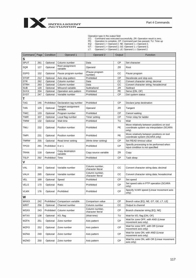
117
Part 4 Commands
Operation type in the output field CC: Command was executed successfully, ZR: Operation result is zero, PE: Operation is complete, CP: Command part has passed, TU: Time up EQ: Operand 1 = Operand 2, NE: Operand 1 ≠ Operand 2, GT: Operand 1 > Operand 2, GE: Operand 1 ≥ Operand 2, LT: Operand 1 < Operand 2, LE: Operand 1 ≤ Operand 2
Command Page Condition Operand 1 Operand 2 Output Function
S SPUT 261 Optional Column number Data CP Set character
SQR 127 Optional Root assignment variable Operand ZR Root
SSPG 152 Optional Pause program number (Pause program number) CC Pause program
STOP 212 Optional Axis stop pattern Prohibited CP Decelerate and stop axis STR 262 Optional Column number Data CC Convert character string; decimal STRH 263 Optional Column number Data CC Convert character string; hexadecimal SUB 120 Optional Minuend variable Subtrahend ZR Subtract SVXX 204 Optional Operation axis pattern Prohibited PE Servo [ON, OF] SYST 247 Optional Variable number Prohibited CP Get system status
T TAG 146 Prohibited Declaration tag number Prohibited CP Declare jump destination
TAN 125 Optional Tangent assignment variable Operand ZR Tangent
TIMC 133 Optional Program number Prohibited CP Cancel waiting TIMR 337 Optional Local flag number Timer setting CP Timer relay for ladder TIMW 132 Optional Wait time Prohibited TU Wait
TMLI 232 Optional Position number Prohibited PE Move relatively between positions on tool coordinate system via interpolation (SCARA only)
TMPI 231 Optional Position number Prohibited PE Move relatively between positions on tool coordinate system (SCARA only)
TMRW 255 Optional Read timer setting (Write timer setting) CP Set READ timeout value
TPCD 291 Prohibited 0 or 1 Prohibited CP Specify processing to be performed when input condition is not specified
TRAN 118 Optional Copy destination variable Copy source variable ZR Copy
TSLP 292 Prohibited Time Prohibited CP Task sleep
V VAL 264 Optional Variable number Column number,
character literal CC Convert character string data; decimal
VALH 265 Optional Variable number Column number, character literal CC Convert character string data; hexadecimal
VEL 169 Optional Speed Prohibited CP Set speed
VELS 170 Optional Ratio Prohibited CP Set speed ratio in PTP operation (SCARA only)
VLMX 176 Optional Prohibited Prohibited CP Specify VLMX speed (Linear movement axis only)
W WHXX 242 Prohibited Comparison variable Comparison value CP Branch value [EQ, NE, GT, GE, LT, LE] WRIT 256 Optional Channel number Column number CC Output to channel
WSXX 243 Prohibited Column number Column number, character literal CP Branch character string [EQ, NE]
WTXX 138 Optional I/O, flag (Wait time) TU Wait for I/O, flag [ON, OF]
WZFA 251 Optional Zone number Axis pattern CP Wait for zone OFF, with AND (Linear movement axis only)
WZFO 252 Optional Zone number Axis pattern CP Wait for zone OFF, with OR (Linear movement axis only)
WZNA 249 Optional Zone number Axis pattern CP Wait for zone ON, with AND (Linear movement axis only)
WZNO 250 Optional Zone number Axis pattern CP Wait for zone ON, with OR (Linear movement axis only)
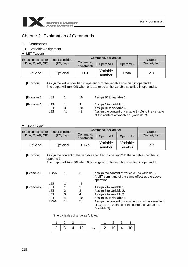
118
Part 4 Commands
Chapter 2 Explanation of Commands 1. Commands 1.1 Variable Assignment
LET (Assign) Command, declaration Extension condition
(LD, A, O, AB, OB) Input condition
(I/O, flag) Command, declaration Operand 1 Operand 2
Output (Output, flag)
Optional Optional LET Variable number Data ZR
[Function] Assign the value specified in operand 2 to the variable specified in operand 1.
The output will turn ON when 0 is assigned to the variable specified in operand 1.
[Example 1] LET 1 10 Assign 10 to variable 1. [Example 2] LET 1 2 Assign 2 to variable 1. LET 3 10 Assign 10 to variable 3. LET *1 *3 Assign the content of variable 3 (10) to the variable
of the content of variable 1 (variable 2).
TRAN (Copy) Command, declaration Extension condition
(LD, A, O, AB, OB) Input condition
(I/O, flag) Command, declaration Operand 1 Operand 2
Output (Output, flag)
Optional Optional TRAN Variable number
Variable number ZR
[Function] Assign the content of the variable specified in operand 2 to the variable specified in
operand 1. The output will turn ON when 0 is assigned to the variable specified in operand 1.
[Example 1] TRAN 1 2 Assign the content of variable 2 to variable 1. A LET command of the same effect as the above
operation LET 1 *2 [Example 2] LET 1 2 Assign 2 to variable 1. LET 2 3 Assign 3 to variable 2. LET 3 4 Assign 4 to variable 3. LET 4 10 Assign 10 to variable 4. TRAN *1 *3 Assign the content of variable 3 (which is variable 4,
or 10) to the variable of the content of variable 1 (variable 2).
The variables change as follows:
1 2 3 4 1 2 3 4
2 3 4 10 → 2 10 4 10

119
Part 4 Commands
CLR (Clear variable)
Command, declaration Extension condition (LD, A, O, AB, OB)
Input condition (I/O, flag) Command,
declaration Operand 1 Operand 2 Output
(Output, flag)
Optional Optional CLR Variable number
Variable number ZR
[Function] Clear the variables from the one specified in operand 1 through the other specified in
operand 2. The contents of the variables that have been cleared become 0. The output will turn ON when 0 is assigned to the variable specified in operand 1.
[Example 1] CLR 1 5 Clear variables 1 through 5. [Example 2] LET 1 10 Assign 10 to variable 1. LET 2 20 Assign 20 to variable 2. CLR *1 *2 Clear the variables from the content of variable 1
(variable 10) through the content of variable 2 (variable 20).
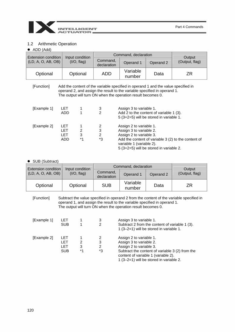
120
Part 4 Commands
1.2 Arithmetic Operation
ADD (Add) Command, declaration Extension condition
(LD, A, O, AB, OB) Input condition
(I/O, flag) Command, declaration Operand 1 Operand 2
Output (Output, flag)
Optional Optional ADD Variable number Data ZR
[Function] Add the content of the variable specified in operand 1 and the value specified in
operand 2, and assign the result to the variable specified in operand 1. The output will turn ON when the operation result becomes 0.
[Example 1] LET 1 3 Assign 3 to variable 1. ADD 1 2 Add 2 to the content of variable 1 (3).
5 (3+2=5) will be stored in variable 1. [Example 2] LET 1 2 Assign 2 to variable 1. LET 2 3 Assign 3 to variable 2. LET 3 2 Assign 2 to variable 3. ADD *1 *3 Add the content of variable 3 (2) to the content of
variable 1 (variable 2). 5 (3+2=5) will be stored in variable 2.
SUB (Subtract) Command, declaration Extension condition
(LD, A, O, AB, OB) Input condition
(I/O, flag) Command, declaration Operand 1 Operand 2
Output (Output, flag)
Optional Optional SUB Variable number Data ZR
[Function] Subtract the value specified in operand 2 from the content of the variable specified in
operand 1, and assign the result to the variable specified in operand 1. The output will turn ON when the operation result becomes 0.
[Example 1] LET 1 3 Assign 3 to variable 1. SUB 1 2 Subtract 2 from the content of variable 1 (3).
1 (3–2=1) will be stored in variable 1. [Example 2] LET 1 2 Assign 2 to variable 1. LET 2 3 Assign 3 to variable 2. LET 3 2 Assign 2 to variable 3. SUB *1 *3 Subtract the content of variable 3 (2) from the
content of variable 1 (variable 2). 1 (3–2=1) will be stored in variable 2.
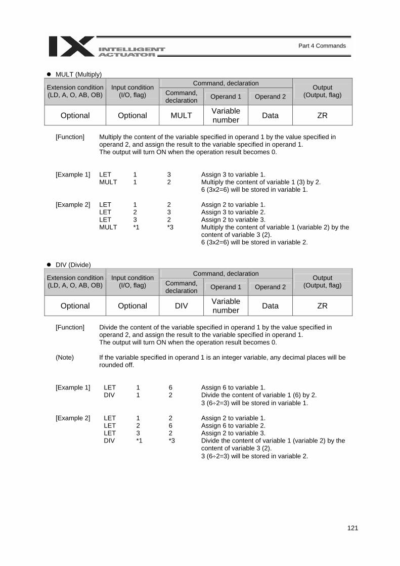
121
Part 4 Commands
MULT (Multiply)
Command, declaration Extension condition (LD, A, O, AB, OB)
Input condition (I/O, flag) Command,
declaration Operand 1 Operand 2 Output
(Output, flag)
Optional Optional MULT Variable number Data ZR
[Function] Multiply the content of the variable specified in operand 1 by the value specified in
operand 2, and assign the result to the variable specified in operand 1. The output will turn ON when the operation result becomes 0.
[Example 1] LET 1 3 Assign 3 to variable 1. MULT 1 2 Multiply the content of variable 1 (3) by 2.
6 (3x2=6) will be stored in variable 1. [Example 2] LET 1 2 Assign 2 to variable 1. LET 2 3 Assign 3 to variable 2. LET 3 2 Assign 2 to variable 3. MULT *1 *3 Multiply the content of variable 1 (variable 2) by the
content of variable 3 (2). 6 (3x2=6) will be stored in variable 2.
DIV (Divide) Command, declaration Extension condition
(LD, A, O, AB, OB) Input condition
(I/O, flag) Command, declaration Operand 1 Operand 2
Output (Output, flag)
Optional Optional DIV Variable number Data ZR
[Function] Divide the content of the variable specified in operand 1 by the value specified in
operand 2, and assign the result to the variable specified in operand 1. The output will turn ON when the operation result becomes 0.
(Note) If the variable specified in operand 1 is an integer variable, any decimal places will be
rounded off.
[Example 1] LET 1 6 Assign 6 to variable 1. DIV 1 2 Divide the content of variable 1 (6) by 2.
3 (6÷2=3) will be stored in variable 1. [Example 2] LET 1 2 Assign 2 to variable 1. LET 2 6 Assign 6 to variable 2. LET 3 2 Assign 2 to variable 3. DIV *1 *3 Divide the content of variable 1 (variable 2) by the
content of variable 3 (2). 3 (6÷2=3) will be stored in variable 2.
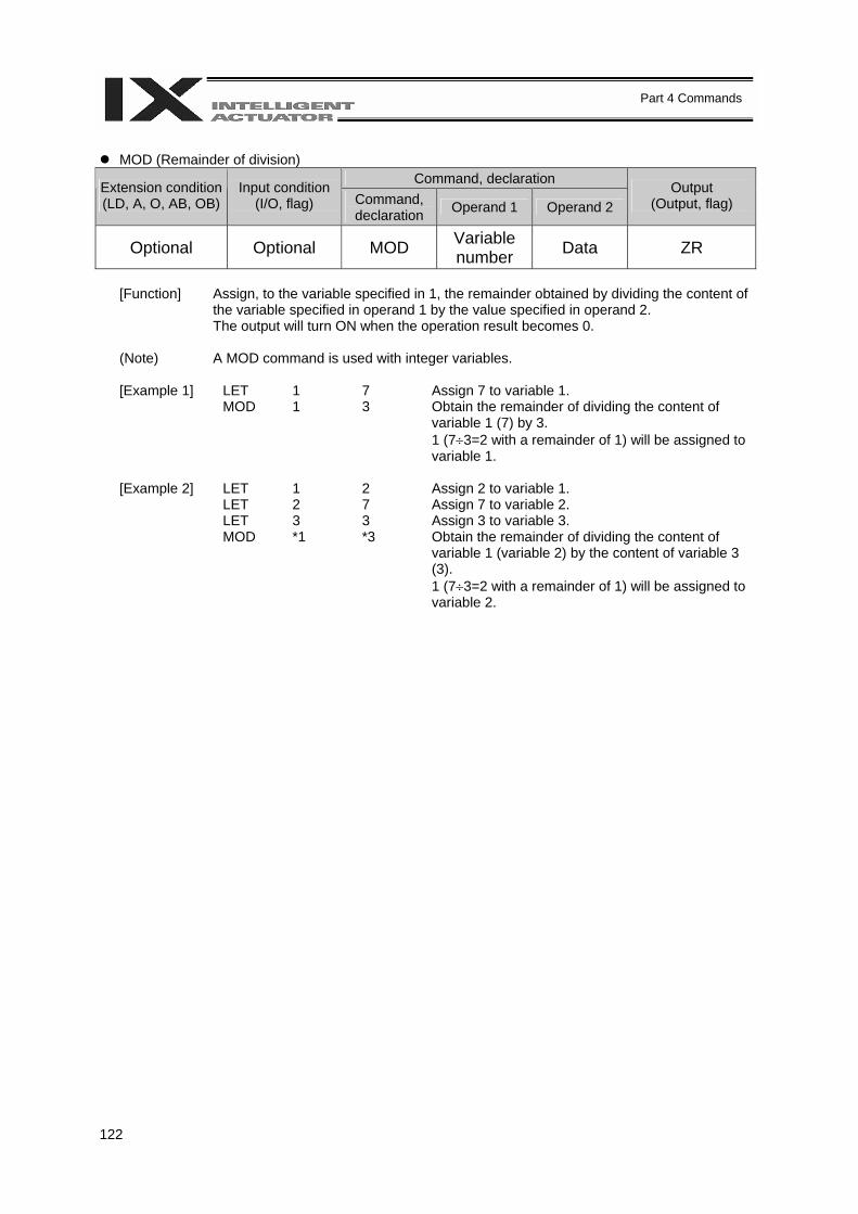
122
Part 4 Commands
MOD (Remainder of division)
Command, declaration Extension condition (LD, A, O, AB, OB)
Input condition (I/O, flag) Command,
declaration Operand 1 Operand 2 Output
(Output, flag)
Optional Optional MOD Variable number Data ZR
[Function] Assign, to the variable specified in 1, the remainder obtained by dividing the content of
the variable specified in operand 1 by the value specified in operand 2. The output will turn ON when the operation result becomes 0.
(Note) A MOD command is used with integer variables. [Example 1] LET 1 7 Assign 7 to variable 1. MOD 1 3 Obtain the remainder of dividing the content of
variable 1 (7) by 3. 1 (7÷3=2 with a remainder of 1) will be assigned to variable 1.
[Example 2] LET 1 2 Assign 2 to variable 1. LET 2 7 Assign 7 to variable 2. LET 3 3 Assign 3 to variable 3. MOD *1 *3 Obtain the remainder of dividing the content of
variable 1 (variable 2) by the content of variable 3 (3). 1 (7÷3=2 with a remainder of 1) will be assigned to variable 2.
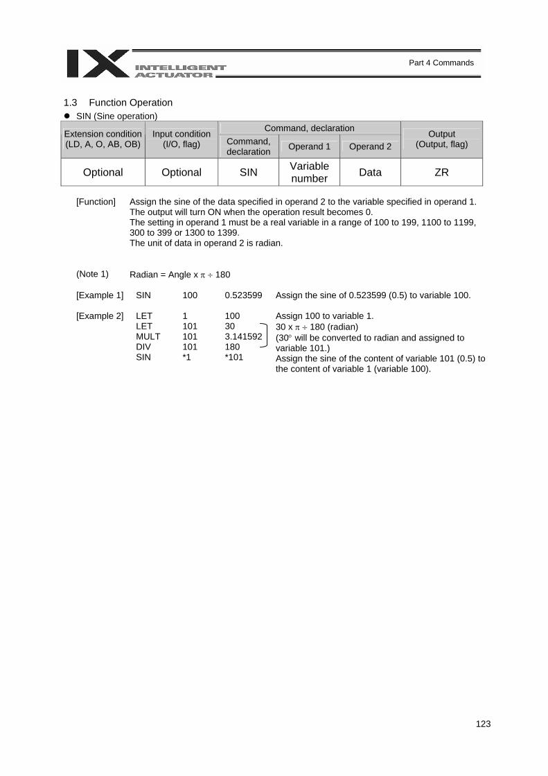
123
Part 4 Commands
1.3 Function Operation
SIN (Sine operation) Command, declaration Extension condition
(LD, A, O, AB, OB) Input condition
(I/O, flag) Command, declaration Operand 1 Operand 2
Output (Output, flag)
Optional Optional SIN Variable number Data ZR
[Function] Assign the sine of the data specified in operand 2 to the variable specified in operand 1.
The output will turn ON when the operation result becomes 0. The setting in operand 1 must be a real variable in a range of 100 to 199, 1100 to 1199, 300 to 399 or 1300 to 1399. The unit of data in operand 2 is radian.
(Note 1) Radian = Angle x π ÷ 180 [Example 1] SIN 100 0.523599 Assign the sine of 0.523599 (0.5) to variable 100. [Example 2] LET 1 100 LET 101 30 MULT 101 3.141592 DIV 101 180 SIN *1 *101
Assign 100 to variable 1. 30 x π ÷ 180 (radian) (30° will be converted to radian and assigned to variable 101.) Assign the sine of the content of variable 101 (0.5) to the content of variable 1 (variable 100).
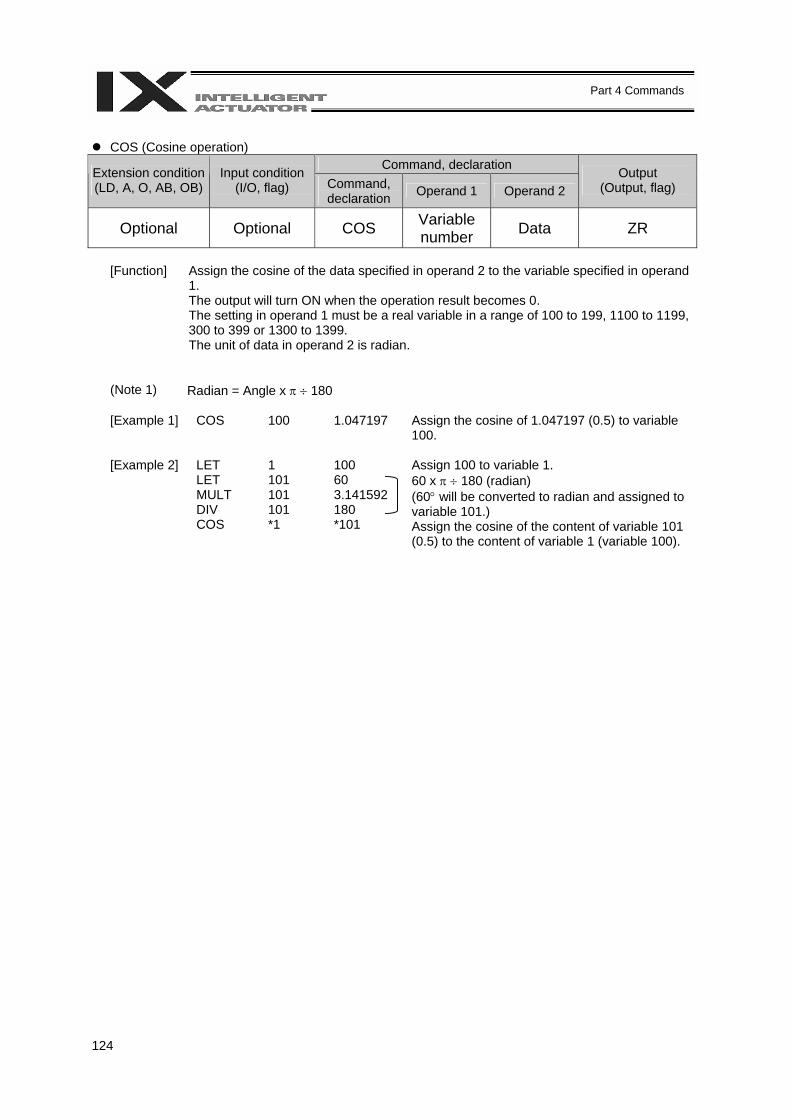
124
Part 4 Commands
COS (Cosine operation)
Command, declaration Extension condition (LD, A, O, AB, OB)
Input condition (I/O, flag) Command,
declaration Operand 1 Operand 2 Output
(Output, flag)
Optional Optional COS Variable number Data ZR
[Function] Assign the cosine of the data specified in operand 2 to the variable specified in operand
1. The output will turn ON when the operation result becomes 0. The setting in operand 1 must be a real variable in a range of 100 to 199, 1100 to 1199, 300 to 399 or 1300 to 1399. The unit of data in operand 2 is radian.
(Note 1) Radian = Angle x π ÷ 180 [Example 1] COS 100 1.047197 Assign the cosine of 1.047197 (0.5) to variable
100. [Example 2] LET 1 100 LET 101 60 MULT 101 3.141592 DIV 101 180 COS *1 *101
Assign 100 to variable 1. 60 x π ÷ 180 (radian) (60° will be converted to radian and assigned to variable 101.) Assign the cosine of the content of variable 101 (0.5) to the content of variable 1 (variable 100).
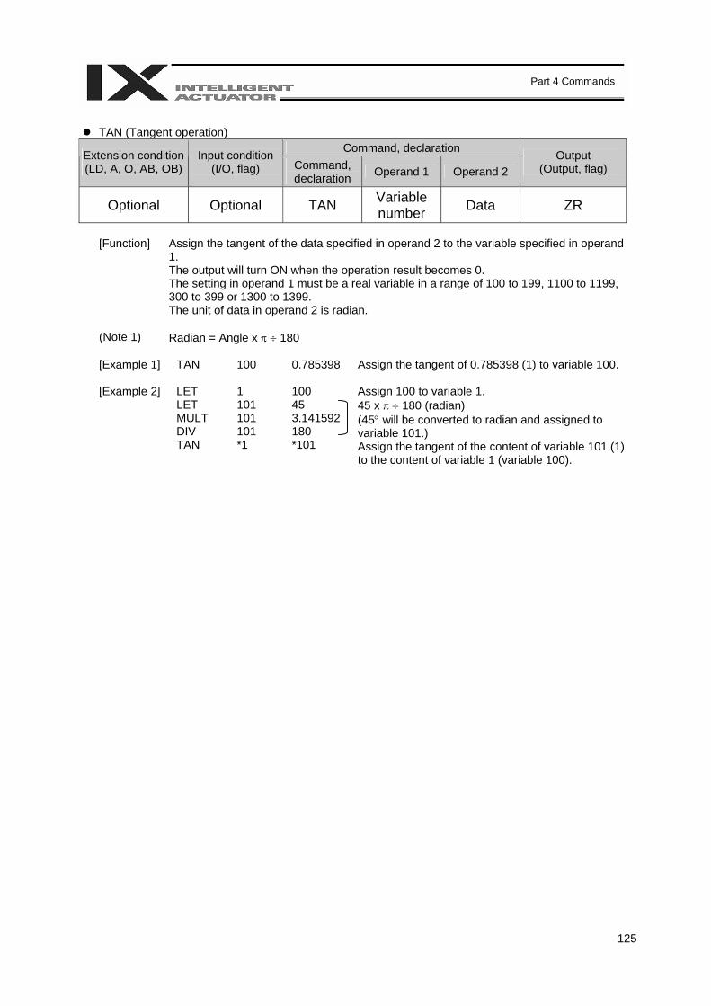
125
Part 4 Commands
TAN (Tangent operation)
Command, declaration Extension condition (LD, A, O, AB, OB)
Input condition (I/O, flag) Command,
declaration Operand 1 Operand 2 Output
(Output, flag)
Optional Optional TAN Variable number Data ZR
[Function] Assign the tangent of the data specified in operand 2 to the variable specified in operand
1. The output will turn ON when the operation result becomes 0. The setting in operand 1 must be a real variable in a range of 100 to 199, 1100 to 1199, 300 to 399 or 1300 to 1399. The unit of data in operand 2 is radian.
(Note 1) Radian = Angle x π ÷ 180 [Example 1] TAN 100 0.785398 Assign the tangent of 0.785398 (1) to variable 100. [Example 2] LET 1 100 LET 101 45 MULT 101 3.141592 DIV 101 180 TAN *1 *101
Assign 100 to variable 1. 45 x π ÷ 180 (radian) (45° will be converted to radian and assigned to variable 101.) Assign the tangent of the content of variable 101 (1) to the content of variable 1 (variable 100).
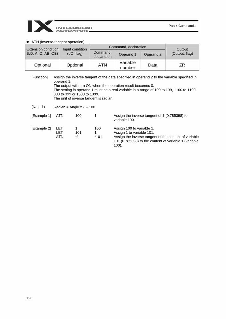
126
Part 4 Commands
ATN (Inverse-tangent operation)
Command, declaration Extension condition (LD, A, O, AB, OB)
Input condition (I/O, flag) Command,
declaration Operand 1 Operand 2 Output
(Output, flag)
Optional Optional ATN Variable number Data ZR
[Function] Assign the inverse tangent of the data specified in operand 2 to the variable specified in
operand 1. The output will turn ON when the operation result becomes 0. The setting in operand 1 must be a real variable in a range of 100 to 199, 1100 to 1199, 300 to 399 or 1300 to 1399. The unit of inverse tangent is radian.
(Note 1) Radian = Angle x π ÷ 180 [Example 1] ATN 100 1 Assign the inverse tangent of 1 (0.785398) to
variable 100. [Example 2] LET 1 100 LET 101 1 ATN *1 *101
Assign 100 to variable 1. Assign 1 to variable 101. Assign the inverse tangent of the content of variable 101 (0.785398) to the content of variable 1 (variable 100).
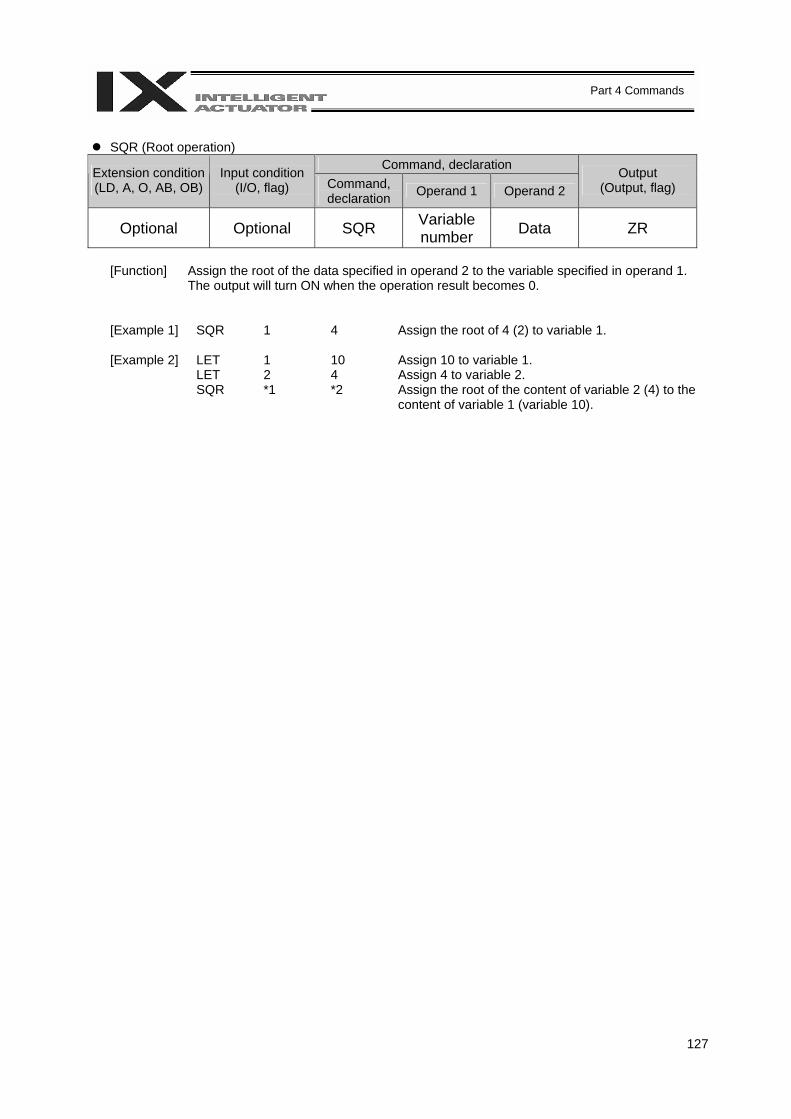
127
Part 4 Commands
SQR (Root operation)
Command, declaration Extension condition (LD, A, O, AB, OB)
Input condition (I/O, flag) Command,
declaration Operand 1 Operand 2 Output
(Output, flag)
Optional Optional SQR Variable number Data ZR
[Function] Assign the root of the data specified in operand 2 to the variable specified in operand 1.
The output will turn ON when the operation result becomes 0.
[Example 1] SQR 1 4 Assign the root of 4 (2) to variable 1. [Example 2] LET 1 10 LET 2 4 SQR *1 *2
Assign 10 to variable 1. Assign 4 to variable 2. Assign the root of the content of variable 2 (4) to the content of variable 1 (variable 10).
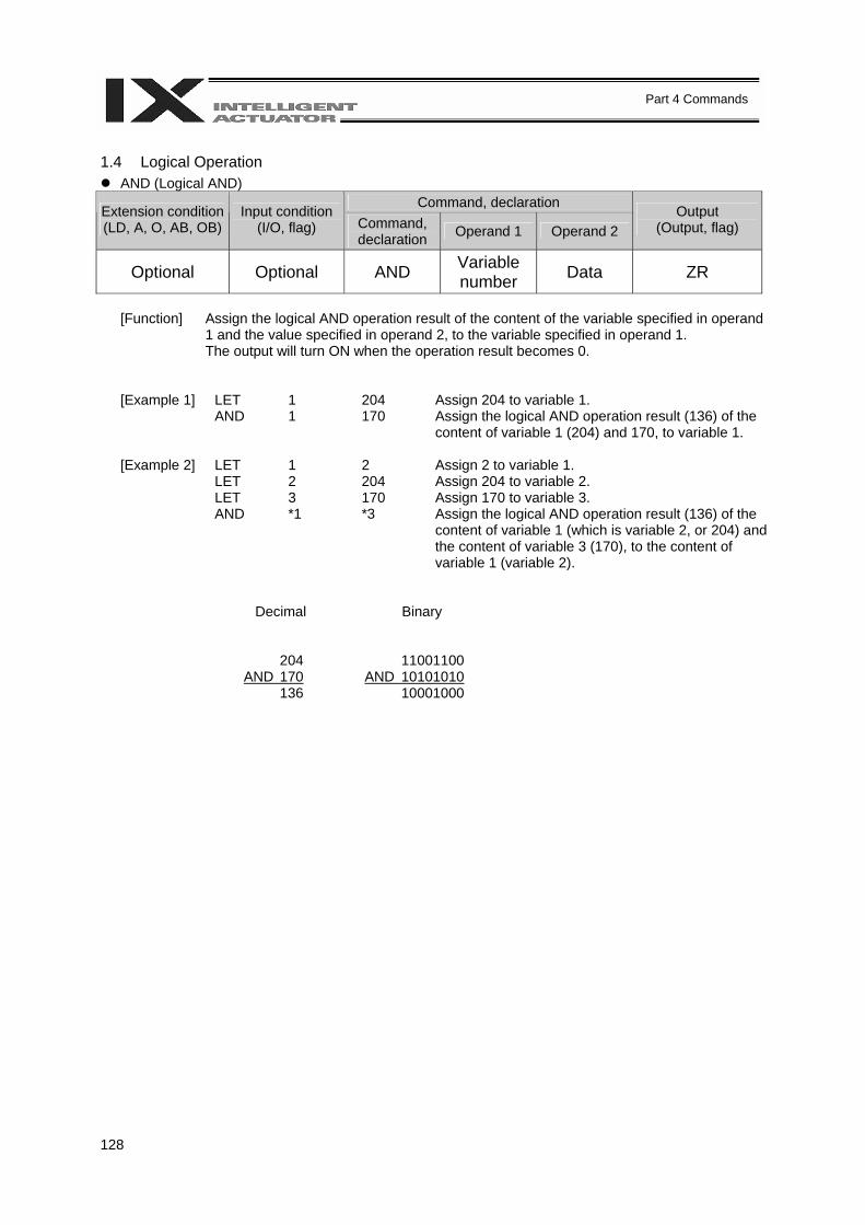
128
Part 4 Commands
1.4 Logical Operation
AND (Logical AND) Command, declaration Extension condition
(LD, A, O, AB, OB) Input condition
(I/O, flag) Command, declaration Operand 1 Operand 2
Output (Output, flag)
Optional Optional AND Variable number Data ZR
[Function] Assign the logical AND operation result of the content of the variable specified in operand
1 and the value specified in operand 2, to the variable specified in operand 1. The output will turn ON when the operation result becomes 0.
[Example 1] LET 1 204 Assign 204 to variable 1. AND 1 170 Assign the logical AND operation result (136) of the
content of variable 1 (204) and 170, to variable 1. [Example 2] LET 1 2 Assign 2 to variable 1. LET 2 204 Assign 204 to variable 2. LET 3 170 Assign 170 to variable 3. AND *1 *3 Assign the logical AND operation result (136) of the
content of variable 1 (which is variable 2, or 204) and the content of variable 3 (170), to the content of variable 1 (variable 2).
Decimal Binary
204 AND 170 136
11001100 AND 10101010 10001000
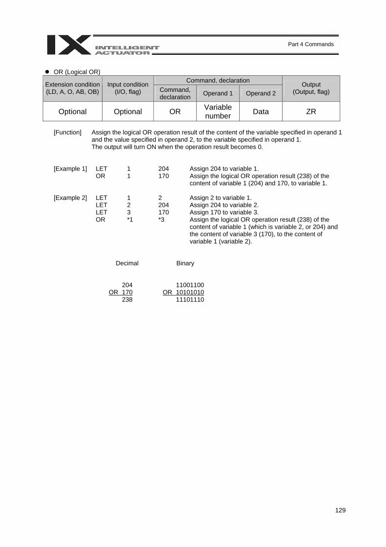
129
Part 4 Commands
OR (Logical OR)
Command, declaration Extension condition (LD, A, O, AB, OB)
Input condition (I/O, flag) Command,
declaration Operand 1 Operand 2 Output
(Output, flag)
Optional Optional OR Variable number Data ZR
[Function] Assign the logical OR operation result of the content of the variable specified in operand 1
and the value specified in operand 2, to the variable specified in operand 1. The output will turn ON when the operation result becomes 0.
[Example 1] LET 1 204 Assign 204 to variable 1. OR 1 170 Assign the logical OR operation result (238) of the
content of variable 1 (204) and 170, to variable 1. [Example 2] LET 1 2 Assign 2 to variable 1. LET 2 204 Assign 204 to variable 2. LET 3 170 Assign 170 to variable 3. OR *1 *3 Assign the logical OR operation result (238) of the
content of variable 1 (which is variable 2, or 204) and the content of variable 3 (170), to the content of variable 1 (variable 2).
Decimal Binary
204 OR 170 238
11001100 OR 10101010 11101110
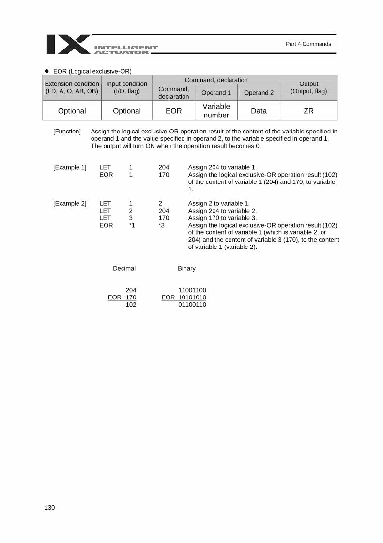
130
Part 4 Commands
EOR (Logical exclusive-OR)
Command, declaration Extension condition (LD, A, O, AB, OB)
Input condition (I/O, flag) Command,
declaration Operand 1 Operand 2 Output
(Output, flag)
Optional Optional EOR Variable number Data ZR
[Function] Assign the logical exclusive-OR operation result of the content of the variable specified in
operand 1 and the value specified in operand 2, to the variable specified in operand 1. The output will turn ON when the operation result becomes 0.
[Example 1] LET 1 204 Assign 204 to variable 1. EOR 1 170 Assign the logical exclusive-OR operation result (102)
of the content of variable 1 (204) and 170, to variable 1.
[Example 2] LET 1 2 Assign 2 to variable 1. LET 2 204 Assign 204 to variable 2. LET 3 170 Assign 170 to variable 3. EOR *1 *3 Assign the logical exclusive-OR operation result (102)
of the content of variable 1 (which is variable 2, or 204) and the content of variable 3 (170), to the content of variable 1 (variable 2).
Decimal Binary
204 EOR 170 102
11001100 EOR 10101010 01100110
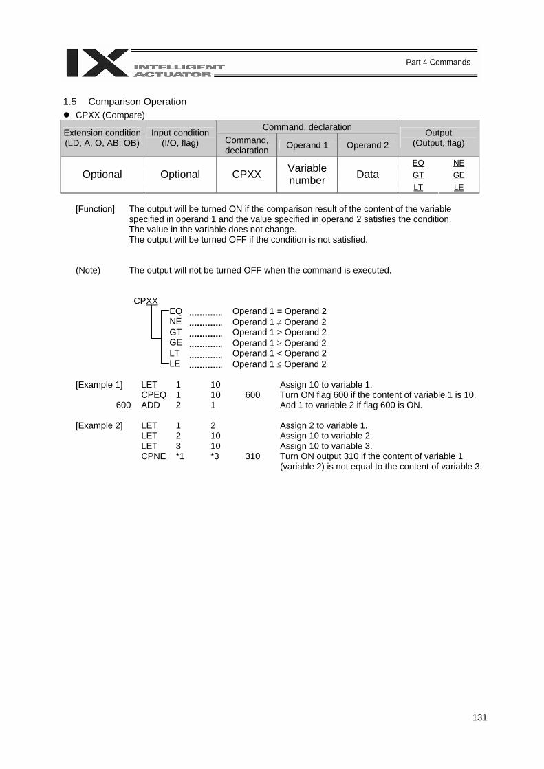
131
Part 4 Commands
1.5 Comparison Operation
CPXX (Compare) Command, declaration Extension condition
(LD, A, O, AB, OB) Input condition
(I/O, flag) Command, declaration Operand 1 Operand 2
Output (Output, flag)
EQ NE GT GE Optional Optional CPXX Variable
number Data LT LE
[Function] The output will be turned ON if the comparison result of the content of the variable
specified in operand 1 and the value specified in operand 2 satisfies the condition. The value in the variable does not change. The output will be turned OFF if the condition is not satisfied.
(Note) The output will not be turned OFF when the command is executed.
CPXX EQ Operand 1 = Operand 2 NE Operand 1 ≠ Operand 2 GT Operand 1 > Operand 2 GE Operand 1 ≥ Operand 2 LT Operand 1 < Operand 2 LE Operand 1 ≤ Operand 2
[Example 1] LET 1 10 Assign 10 to variable 1. CPEQ 1 10 600 Turn ON flag 600 if the content of variable 1 is 10. 600 ADD 2 1 Add 1 to variable 2 if flag 600 is ON. [Example 2] LET 1 2 Assign 2 to variable 1. LET 2 10 Assign 10 to variable 2. LET 3 10 Assign 10 to variable 3. CPNE *1 *3 310 Turn ON output 310 if the content of variable 1
(variable 2) is not equal to the content of variable 3.
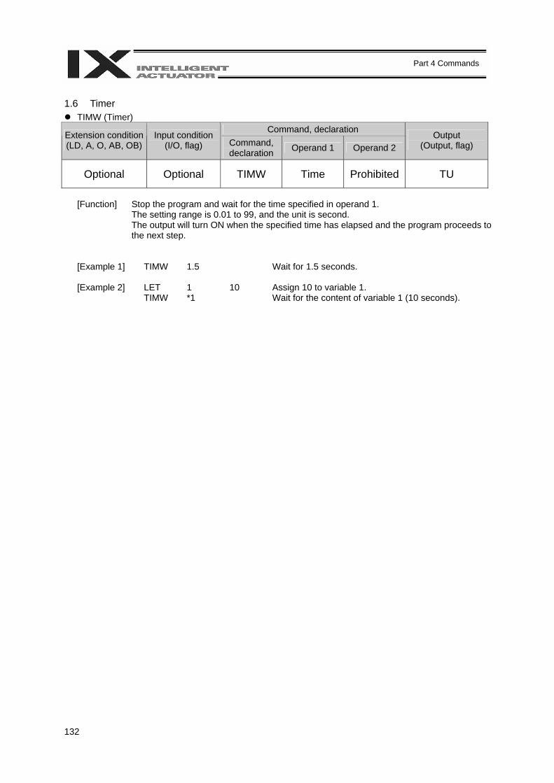
132
Part 4 Commands
1.6 Timer
TIMW (Timer) Command, declaration Extension condition
(LD, A, O, AB, OB) Input condition
(I/O, flag) Command, declaration Operand 1 Operand 2
Output (Output, flag)
Optional Optional TIMW Time Prohibited TU
[Function] Stop the program and wait for the time specified in operand 1.
The setting range is 0.01 to 99, and the unit is second. The output will turn ON when the specified time has elapsed and the program proceeds to the next step.
[Example 1] TIMW 1.5 Wait for 1.5 seconds. [Example 2] LET 1 10 Assign 10 to variable 1. TIMW *1 Wait for the content of variable 1 (10 seconds).
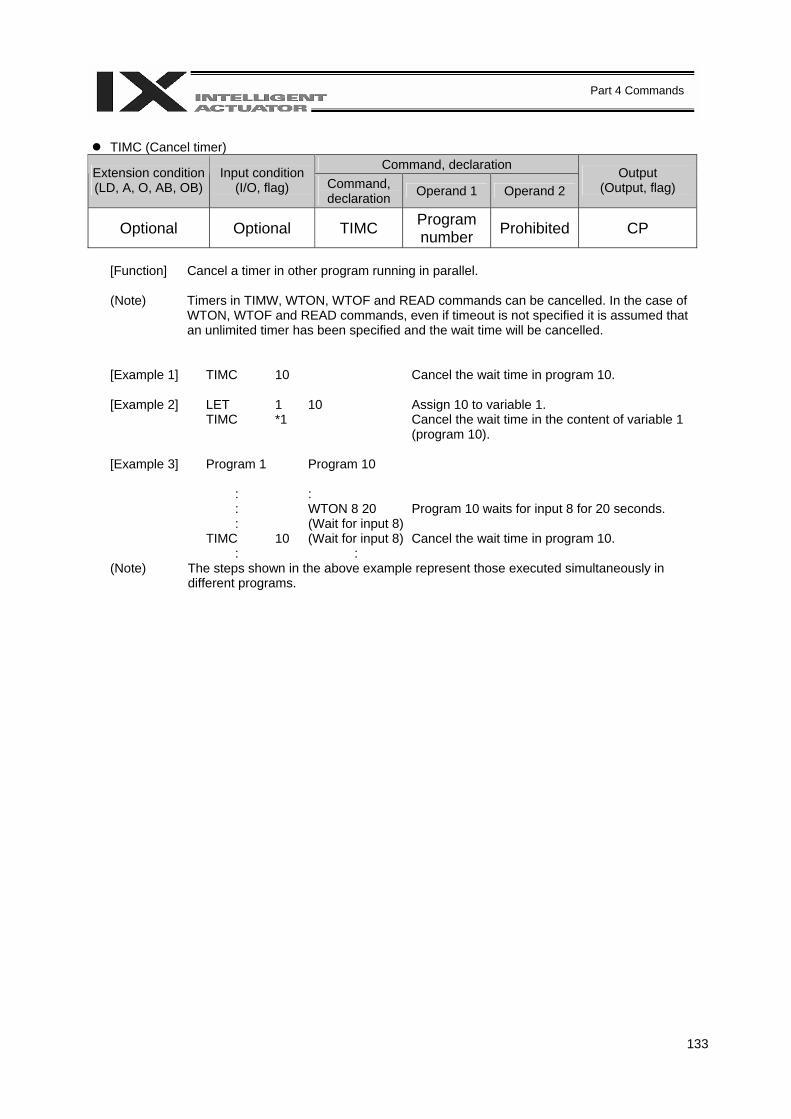
133
Part 4 Commands
TIMC (Cancel timer)
Command, declaration Extension condition (LD, A, O, AB, OB)
Input condition (I/O, flag) Command,
declaration Operand 1 Operand 2 Output
(Output, flag)
Optional Optional TIMC Program number Prohibited CP
[Function] Cancel a timer in other program running in parallel. (Note) Timers in TIMW, WTON, WTOF and READ commands can be cancelled. In the case of
WTON, WTOF and READ commands, even if timeout is not specified it is assumed that an unlimited timer has been specified and the wait time will be cancelled.
[Example 1] TIMC 10 Cancel the wait time in program 10. [Example 2] LET 1 10 Assign 10 to variable 1. TIMC *1 Cancel the wait time in the content of variable 1
(program 10). [Example 3] Program 1 Program 10 : : : WTON 8 20 Program 10 waits for input 8 for 20 seconds. : (Wait for input 8) TIMC 10 (Wait for input 8) Cancel the wait time in program 10. : : (Note) The steps shown in the above example represent those executed simultaneously in
different programs.
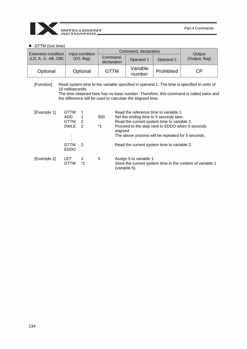
134
Part 4 Commands
GTTM (Get time)
Command, declaration Extension condition (LD, A, O, AB, OB)
Input condition (I/O, flag) Command,
declaration Operand 1 Operand 2 Output
(Output, flag)
Optional Optional GTTM Variable number Prohibited CP
[Function] Read system time to the variable specified in operand 1. The time is specified in units of
10 milliseconds. The time obtained here has no base number. Therefore, this command is called twice and the difference will be used to calculate the elapsed time.
[Example 1] GTTM 1 Read the reference time to variable 1. ADD 1 500 Set the ending time to 5 seconds later. GTTM 2 Read the current system time to variable 2. DWLE 2 *1 Proceed to the step next to EDDO when 5 seconds
elapsed. : The above process will be repeated for 5 seconds. : GTTM 2 Read the current system time to variable 2. EDDO [Example 2] LET 1 5 Assign 5 to variable 1. GTTM *1 Store the current system time in the content of variable 1
(variable 5).
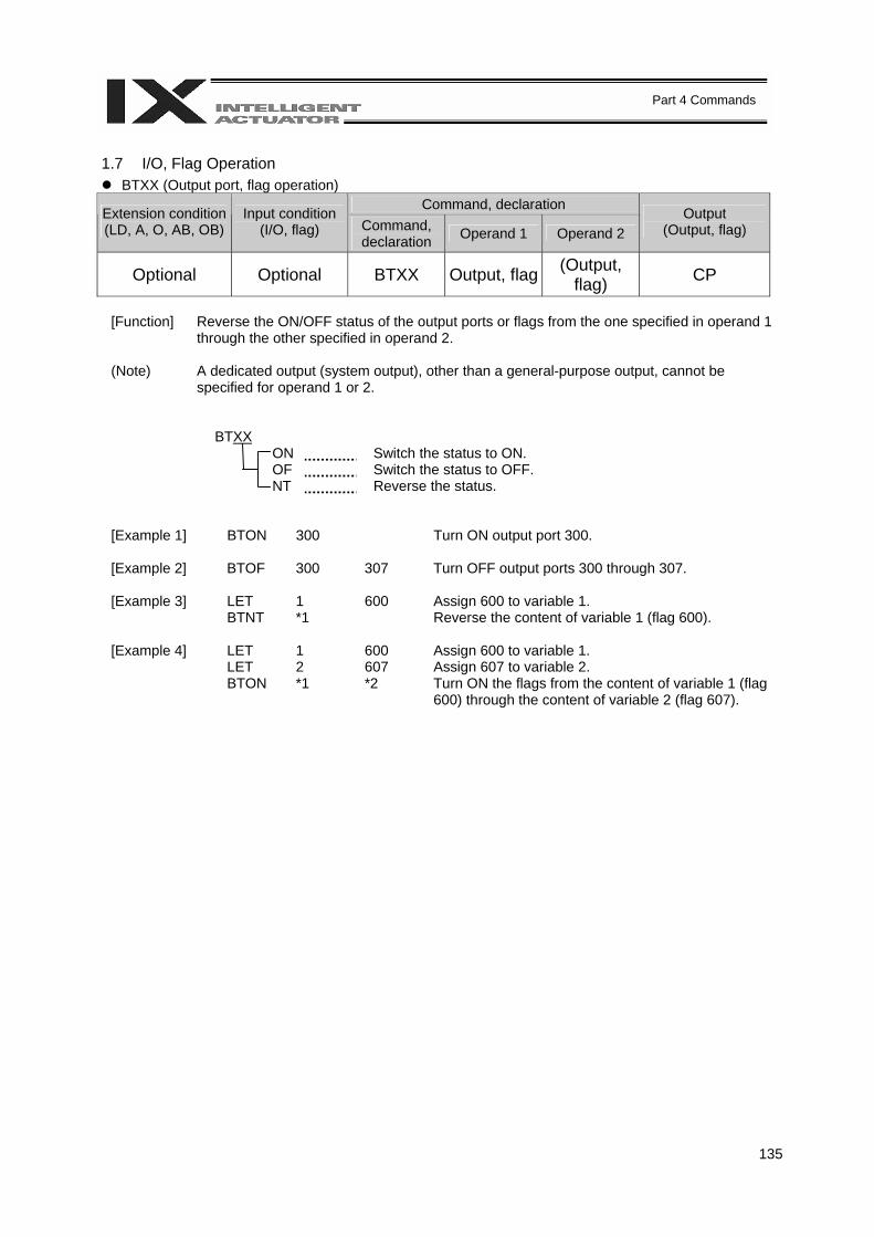
135
Part 4 Commands
1.7 I/O, Flag Operation
BTXX (Output port, flag operation) Command, declaration Extension condition
(LD, A, O, AB, OB) Input condition
(I/O, flag) Command, declaration Operand 1 Operand 2
Output (Output, flag)
Optional Optional BTXX Output, flag (Output, flag) CP
[Function] Reverse the ON/OFF status of the output ports or flags from the one specified in operand 1
through the other specified in operand 2. (Note) A dedicated output (system output), other than a general-purpose output, cannot be
specified for operand 1 or 2.
BTXX ON Switch the status to ON. OF Switch the status to OFF. NT Reverse the status.
[Example 1] BTON 300 Turn ON output port 300. [Example 2] BTOF 300 307 Turn OFF output ports 300 through 307. [Example 3] LET 1 600 Assign 600 to variable 1. BTNT *1 Reverse the content of variable 1 (flag 600). [Example 4] LET 1 600 Assign 600 to variable 1. LET 2 607 Assign 607 to variable 2. BTON *1 *2 Turn ON the flags from the content of variable 1 (flag
600) through the content of variable 2 (flag 607).
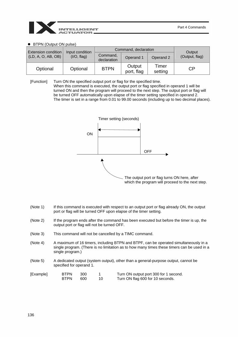
136
Part 4 Commands
BTPN (Output ON pulse)
Command, declaration Extension condition (LD, A, O, AB, OB)
Input condition (I/O, flag) Command,
declaration Operand 1 Operand 2 Output
(Output, flag)
Optional Optional BTPN Output port, flag
Timer setting CP
[Function] Turn ON the specified output port or flag for the specified time.
When this command is executed, the output port or flag specified in operand 1 will be turned ON and then the program will proceed to the next step. The output port or flag will be turned OFF automatically upon elapse of the timer setting specified in operand 2. The timer is set in a range from 0.01 to 99.00 seconds (including up to two decimal places).
(Note 1) If this command is executed with respect to an output port or flag already ON, the output port or flag will be turned OFF upon elapse of the timer setting.
(Note 2) If the program ends after the command has been executed but before the timer is up, the output port or flag will not be turned OFF.
(Note 3) This command will not be cancelled by a TIMC command.
(Note 4) A maximum of 16 timers, including BTPN and BTPF, can be operated simultaneously in a single program. (There is no limitation as to how many times these timers can be used in a single program.)
(Note 5) A dedicated output (system output), other than a general-purpose output, cannot be specified for operand 1.
[Example] BTPN 300 1 Turn ON output port 300 for 1 second. BTPN 600 10 Turn ON flag 600 for 10 seconds.
Timer setting (seconds)
The output port or flag turns ON here, after which the program will proceed to the next step.
ON
OFF

137
Part 4 Commands
BTPF (Output OFF pulse)
Command, declaration Extension condition (LD, A, O, AB, OB)
Input condition (I/O, flag) Command,
declaration Operand 1 Operand 2 Output
(Output, flag)
Optional Optional BTPF Output port, flag
Timer setting CP
[Function] Turn OFF the specified output port or flag for the specified time.
When this command is executed, the output port or flag specified in operand 1 will be turned OFF and then the program will proceed to the next step. The output port or flag will be turned ON automatically upon elapse of the timer setting specified in operand 2. The timer is set in a range from 0.01 to 99.00 seconds (including up to two decimal places).
(Note 1) If this command is executed with respect to an output port or flag already OFF, the output port or flag will be turned ON upon elapse of the timer setting.
(Note 2) If the program ends after the command has been executed but before the timer is up, the output port or flag will not be turned ON.
(Note 3) This command will not be cancelled by a TIMC command.
(Note 4) A maximum of 16 timers, including BTPN and BTPF, can be operated simultaneously in a single program. (There is no limitation as to how many times these timers can be used in a single program.)
(Note 5) A dedicated output (system output), other than a general-purpose output, cannot be specified for operand 1.
[Example] BTPF 300 1 Turn OFF output port 300 for 1 second. BTPF 600 10 Turn OFF flag 600 for 10 seconds.
Timer setting (seconds)
The output port or flag turns OFF here, after which the program will proceed to the next step.
ON
OFF
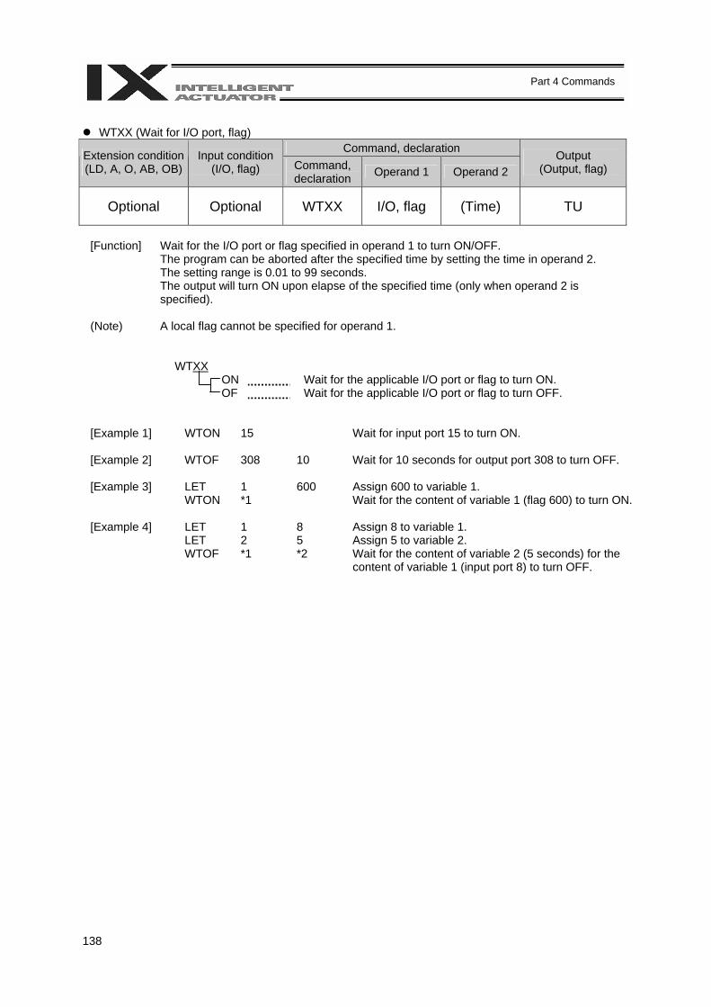
138
Part 4 Commands
WTXX (Wait for I/O port, flag)
Command, declaration Extension condition (LD, A, O, AB, OB)
Input condition (I/O, flag) Command,
declaration Operand 1 Operand 2 Output
(Output, flag)
Optional Optional WTXX I/O, flag (Time) TU
[Function] Wait for the I/O port or flag specified in operand 1 to turn ON/OFF.
The program can be aborted after the specified time by setting the time in operand 2. The setting range is 0.01 to 99 seconds. The output will turn ON upon elapse of the specified time (only when operand 2 is specified).
(Note) A local flag cannot be specified for operand 1.
WTXX ON Wait for the applicable I/O port or flag to turn ON. OF Wait for the applicable I/O port or flag to turn OFF.
[Example 1] WTON 15 Wait for input port 15 to turn ON. [Example 2] WTOF 308 10 Wait for 10 seconds for output port 308 to turn OFF. [Example 3] LET 1 600 Assign 600 to variable 1. WTON *1 Wait for the content of variable 1 (flag 600) to turn ON. [Example 4] LET 1 8 Assign 8 to variable 1. LET 2 5 Assign 5 to variable 2. WTOF *1 *2 Wait for the content of variable 2 (5 seconds) for the
content of variable 1 (input port 8) to turn OFF.
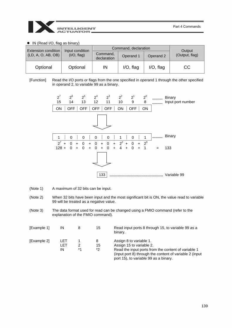
139
Part 4 Commands
IN (Read I/O, flag as binary)
Command, declaration Extension condition (LD, A, O, AB, OB)
Input condition (I/O, flag) Command,
declaration Operand 1 Operand 2 Output
(Output, flag)
Optional Optional IN I/O, flag I/O, flag CC
[Function] Read the I/O ports or flags from the one specified in operand 1 through the other specified
in operand 2, to variable 99 as a binary.
27 26 25 24 23 22 21 20 Binary 15 14 13 12 11 10 9 8 Input port number
ON OFF OFF OFF OFF ON OFF ON
1 0 0 0 0 1 0 1 Binary
27 + 0 + 0 + 0 + 0 + 22 + 0 + 20 128 + 0 + 0 + 0 + 0 + 4 + 0 + 1 = 133
133 Variable 99
(Note 1) A maximum of 32 bits can be input.
(Note 2) When 32 bits have been input and the most significant bit is ON, the value read to variable 99 will be treated as a negative value.
(Note 3) The data format used for read can be changed using a FMIO command (refer to the explanation of the FMIO command).
[Example 1] IN 8 15 Read input ports 8 through 15, to variable 99 as a binary.
[Example 2] LET 1 8 Assign 8 to variable 1. LET 2 15 Assign 15 to variable 2. IN *1 *2 Read the input ports from the content of variable 1
(input port 8) through the content of variable 2 (input port 15), to variable 99 as a binary.
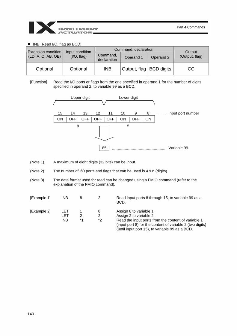
140
Part 4 Commands
INB (Read I/O, flag as BCD)
Command, declaration Extension condition (LD, A, O, AB, OB)
Input condition (I/O, flag) Command,
declaration Operand 1 Operand 2 Output
(Output, flag)
Optional Optional INB Output, flag BCD digits CC
[Function] Read the I/O ports or flags from the one specified in operand 1 for the number of digits
specified in operand 2, to variable 99 as a BCD.
15 14 13 12 11 10 9 8 Input port number ON OFF OFF OFF OFF ON OFF ON
85 Variable 99
(Note 1) A maximum of eight digits (32 bits) can be input.
(Note 2) The number of I/O ports and flags that can be used is 4 x n (digits).
(Note 3) The data format used for read can be changed using a FMIO command (refer to the explanation of the FMIO command).
[Example 1] INB 8 2 Read input ports 8 through 15, to variable 99 as a BCD.
[Example 2] LET 1 8 Assign 8 to variable 1. LET 2 2 Assign 2 to variable 2. INB *1 *2 Read the input ports from the content of variable 1
(input port 8) for the content of variable 2 (two digits) (until input port 15), to variable 99 as a BCD.
Upper digit Lower digit
8 5
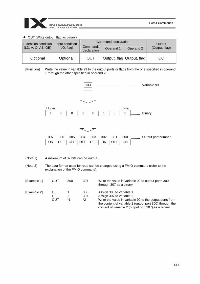
141
Part 4 Commands
OUT (Write output, flag as binary)
Command, declaration Extension condition (LD, A, O, AB, OB)
Input condition (I/O, flag) Command,
declaration Operand 1 Operand 2 Output
(Output, flag)
Optional Optional OUT Output, flag Output, flag CC
[Function] Write the value in variable 99 to the output ports or flags from the one specified in operand
1 through the other specified in operand 2.
133 Variable 99
Upper Lower 1 0 0 0 0 1 0 1 Binary
307 306 305 304 303 302 301 300 Output port number ON OFF OFF OFF OFF ON OFF ON
(Note 1) A maximum of 32 bits can be output.
(Note 2) The data format used for read can be changed using a FMIO command (refer to the explanation of the FMIO command).
[Example 1] OUT 300 307 Write the value in variable 99 to output ports 300 through 307 as a binary.
[Example 2] LET 1 300 Assign 300 to variable 1. LET 2 307 Assign 307 to variable 2. OUT *1 *2 Write the value in variable 99 to the output ports from
the content of variable 1 (output port 300) through the content of variable 2 (output port 307) as a binary.
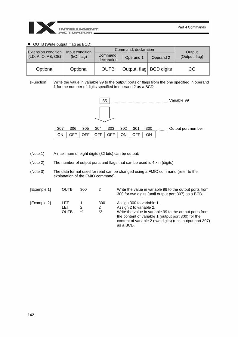
142
Part 4 Commands
OUTB (Write output, flag as BCD)
Command, declaration Extension condition (LD, A, O, AB, OB)
Input condition (I/O, flag) Command,
declaration Operand 1 Operand 2 Output
(Output, flag)
Optional Optional OUTB Output, flag BCD digits CC
[Function] Write the value in variable 99 to the output ports or flags from the one specified in operand
1 for the number of digits specified in operand 2 as a BCD.
85 Variable 99
307 306 305 304 303 302 301 300 Output port number ON OFF OFF OFF OFF ON OFF ON
(Note 1) A maximum of eight digits (32 bits) can be output.
(Note 2) The number of output ports and flags that can be used is 4 x n (digits).
(Note 3) The data format used for read can be changed using a FMIO command (refer to the explanation of the FMIO command).
[Example 1] OUTB 300 2 Write the value in variable 99 to the output ports from 300 for two digits (until output port 307) as a BCD.
[Example 2] LET 1 300 Assign 300 to variable 1. LET 2 2 Assign 2 to variable 2. OUTB *1 *2 Write the value in variable 99 to the output ports from
the content of variable 1 (output port 300) for the content of variable 2 (two digits) (until output port 307) as a BCD.
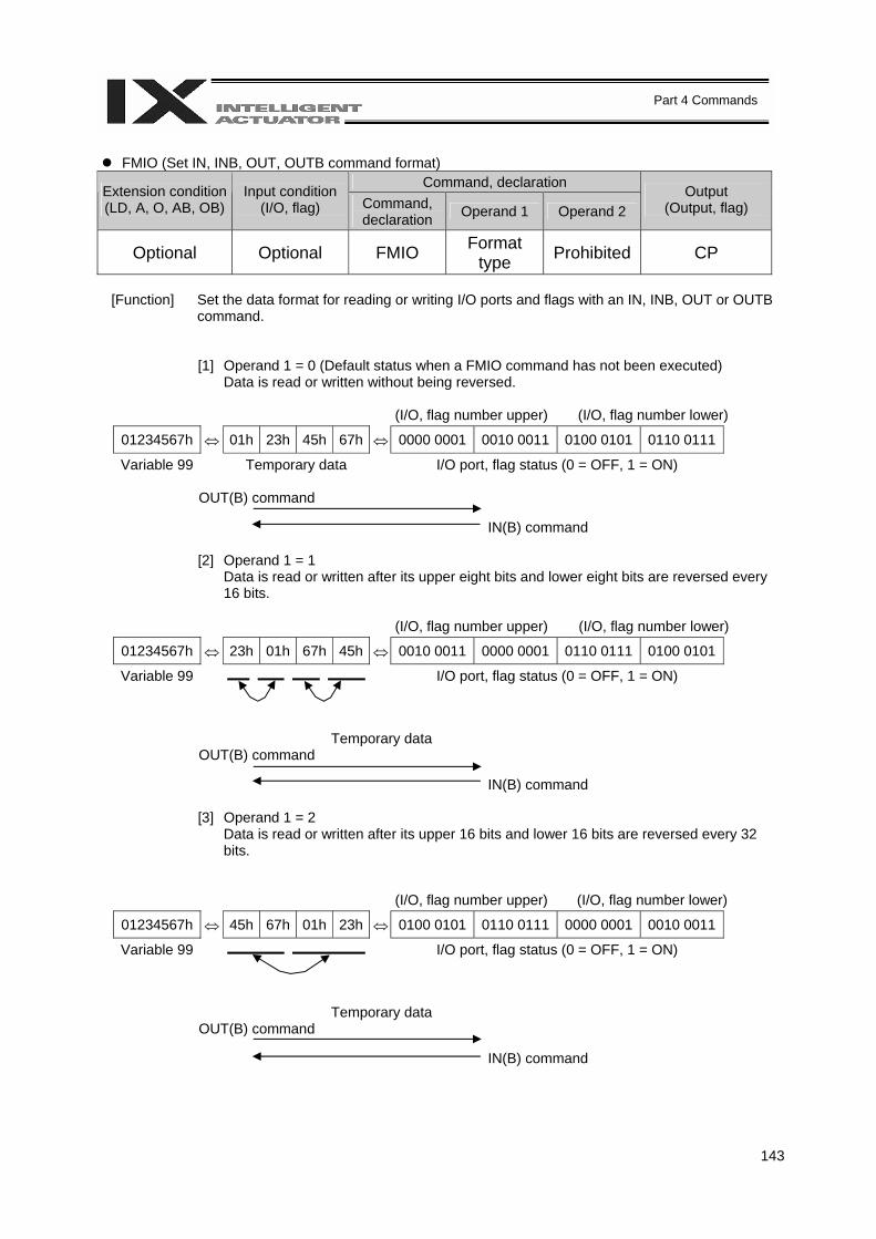
143
Part 4 Commands
FMIO (Set IN, INB, OUT, OUTB command format)
Command, declaration Extension condition (LD, A, O, AB, OB)
Input condition (I/O, flag) Command,
declaration Operand 1 Operand 2 Output
(Output, flag)
Optional Optional FMIO Format type Prohibited CP
[Function] Set the data format for reading or writing I/O ports and flags with an IN, INB, OUT or OUTB
command.
[1] Operand 1 = 0 (Default status when a FMIO command has not been executed) Data is read or written without being reversed.
(I/O, flag number upper) (I/O, flag number lower)
01234567h ⇔ 01h 23h 45h 67h ⇔ 0000 0001 0010 0011 0100 0101 0110 0111
Variable 99 Temporary data I/O port, flag status (0 = OFF, 1 = ON)
OUT(B) command
IN(B) command
[2] Operand 1 = 1 Data is read or written after its upper eight bits and lower eight bits are reversed every 16 bits.
(I/O, flag number upper) (I/O, flag number lower)
01234567h ⇔ 23h 01h 67h 45h ⇔ 0010 0011 0000 0001 0110 0111 0100 0101
Variable 99 I/O port, flag status (0 = OFF, 1 = ON)
Temporary data OUT(B) command
IN(B) command
[3] Operand 1 = 2
Data is read or written after its upper 16 bits and lower 16 bits are reversed every 32 bits.
(I/O, flag number upper) (I/O, flag number lower)
01234567h ⇔ 45h 67h 01h 23h ⇔ 0100 0101 0110 0111 0000 0001 0010 0011
Variable 99 I/O port, flag status (0 = OFF, 1 = ON)
Temporary data OUT(B) command
IN(B) command
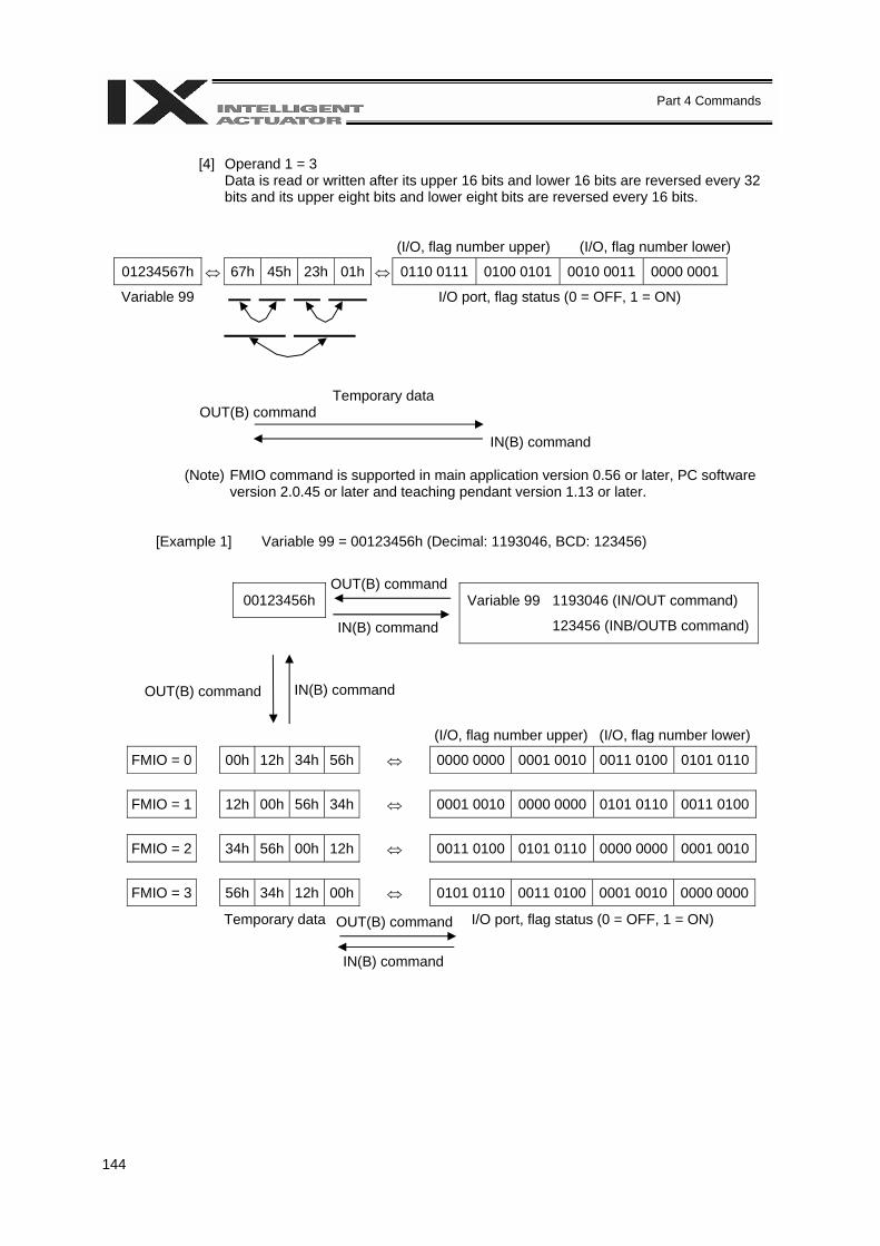
144
Part 4 Commands
[4] Operand 1 = 3
Data is read or written after its upper 16 bits and lower 16 bits are reversed every 32 bits and its upper eight bits and lower eight bits are reversed every 16 bits.
(I/O, flag number upper) (I/O, flag number lower)
01234567h ⇔ 67h 45h 23h 01h ⇔ 0110 0111 0100 0101 0010 0011 0000 0001
Variable 99 I/O port, flag status (0 = OFF, 1 = ON)
Temporary data OUT(B) command
IN(B) command
(Note) FMIO command is supported in main application version 0.56 or later, PC software
version 2.0.45 or later and teaching pendant version 1.13 or later.
[Example 1] Variable 99 = 00123456h (Decimal: 1193046, BCD: 123456)
00123456h
Variable 99 1193046 (IN/OUT command)
123456 (INB/OUTB command)
(I/O, flag number upper) (I/O, flag number lower)
FMIO = 0 00h 12h 34h 56h ⇔ 0000 0000 0001 0010 0011 0100 0101 0110
FMIO = 1 12h 00h 56h 34h ⇔ 0001 0010 0000 0000 0101 0110 0011 0100
FMIO = 2 34h 56h 00h 12h ⇔ 0011 0100 0101 0110 0000 0000 0001 0010
FMIO = 3 56h 34h 12h 00h ⇔ 0101 0110 0011 0100 0001 0010 0000 0000
Temporary data I/O port, flag status (0 = OFF, 1 = ON)
OUT(B) command
IN(B) command
OUT(B) command IN(B) command
OUT(B) command
IN(B) command
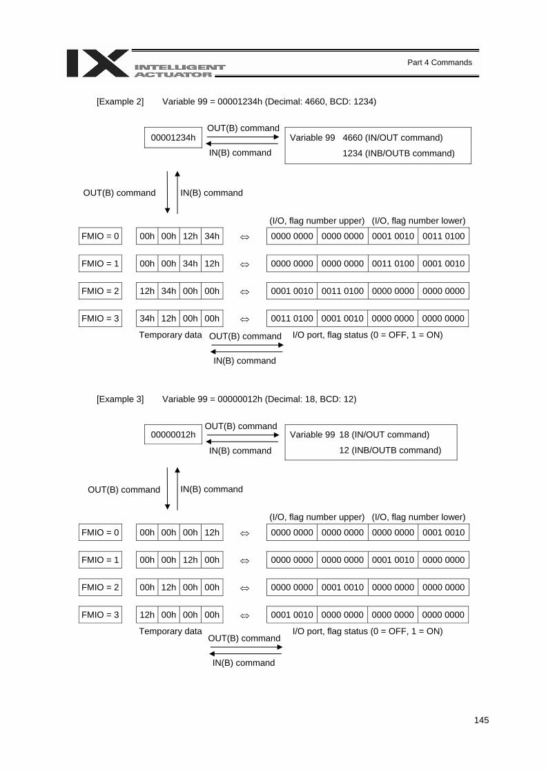
145
Part 4 Commands
[Example 2] Variable 99 = 00001234h (Decimal: 4660, BCD: 1234)
00001234h
Variable 99 4660 (IN/OUT command)
1234 (INB/OUTB command)
(I/O, flag number upper) (I/O, flag number lower)
FMIO = 0 00h 00h 12h 34h ⇔ 0000 0000 0000 0000 0001 0010 0011 0100
FMIO = 1 00h 00h 34h 12h ⇔ 0000 0000 0000 0000 0011 0100 0001 0010
FMIO = 2 12h 34h 00h 00h ⇔ 0001 0010 0011 0100 0000 0000 0000 0000
FMIO = 3 34h 12h 00h 00h ⇔ 0011 0100 0001 0010 0000 0000 0000 0000
Temporary data I/O port, flag status (0 = OFF, 1 = ON)
[Example 3] Variable 99 = 00000012h (Decimal: 18, BCD: 12)
00000012h
Variable 99 18 (IN/OUT command)
12 (INB/OUTB command)
(I/O, flag number upper) (I/O, flag number lower)
FMIO = 0 00h 00h 00h 12h ⇔ 0000 0000 0000 0000 0000 0000 0001 0010
FMIO = 1 00h 00h 12h 00h ⇔ 0000 0000 0000 0000 0001 0010 0000 0000
FMIO = 2 00h 12h 00h 00h ⇔ 0000 0000 0001 0010 0000 0000 0000 0000
FMIO = 3 12h 00h 00h 00h ⇔ 0001 0010 0000 0000 0000 0000 0000 0000
Temporary data I/O port, flag status (0 = OFF, 1 = ON)
OUT(B) command IN(B) command
OUT(B) command
IN(B) command
OUT(B) command
IN(B) command
OUT(B) command IN(B) command
OUT(B) command
IN(B) command
OUT(B) command
IN(B) command
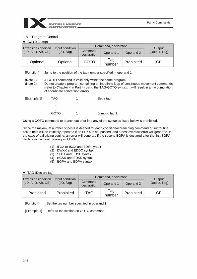
146
Part 4 Commands
1.8 Program Control
GOTO (Jump) Command, declaration Extension condition
(LD, A, O, AB, OB) Input condition
(I/O, flag) Command, declaration Operand 1 Operand 2
Output (Output, flag)
Optional Optional GOTO Tag number Prohibited CP
[Function] Jump to the position of the tag number specified in operand 1. (Note 1) A GOTO command is valid only within the same program. (Note 2) Do not create a program containing an indefinite loop of continuous movement commands
(refer to Chapter 4 in Part 4) using the TAG-GOTO syntax. It will result in an accumulation of coordinate conversion errors.
[Example 1] TAG 1 Set a tag. : : : GOTO 1 Jump to tag 1.
Using a GOTO command to branch out of or into any of the syntaxes listed below is prohibited. Since the maximum number of nests is defined for each conditional branching command or subroutine call, a nest will be infinitely repeated if an EDXX is not passed, and a nest overflow error will generate. In the case of palletizing setting, an error will generate if the second BGPA is declared after the first BGPA declaration without passing an EDPA.
(1) IFXX or ISXX and EDIF syntax (2) DWXX and EDDO syntax (3) SLCT and EDSL syntax (4) BGSR and EDSR syntax (5) BGPA and EDPA syntax
TAG (Declare tag) Command, declaration Extension condition
(LD, A, O, AB, OB) Input condition
(I/O, flag) Command, declaration Operand 1 Operand 2
Output (Output, flag)
Prohibited Prohibited TAG Tag number Prohibited CP
[Function] Set the tag number specified in operand 1. [Example 1] Refer to the section on GOTO command.
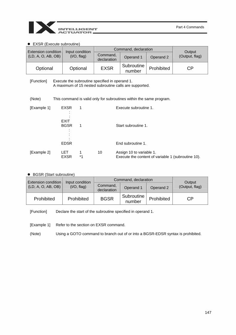
147
Part 4 Commands
EXSR (Execute subroutine)
Command, declaration Extension condition (LD, A, O, AB, OB)
Input condition (I/O, flag) Command,
declaration Operand 1 Operand 2 Output
(Output, flag)
Optional Optional EXSR Subroutine number Prohibited CP
[Function] Execute the subroutine specified in operand 1.
A maximum of 15 nested subroutine calls are supported.
(Note) This command is valid only for subroutines within the same program.
[Example 1] EXSR 1 Execute subroutine 1. : : EXIT BGSR 1 Start subroutine 1. : : : EDSR End subroutine 1. [Example 2] LET 1 10 Assign 10 to variable 1. EXSR *1 Execute the content of variable 1 (subroutine 10).
BGSR (Start subroutine) Command, declaration Extension condition
(LD, A, O, AB, OB) Input condition
(I/O, flag) Command, declaration Operand 1 Operand 2
Output (Output, flag)
Prohibited Prohibited BGSR Subroutine number Prohibited CP
[Function] Declare the start of the subroutine specified in operand 1.
[Example 1] Refer to the section on EXSR command. (Note) Using a GOTO command to branch out of or into a BGSR-EDSR syntax is prohibited.

148
Part 4 Commands
EDSR (End subroutine)
Command, declaration Extension condition (LD, A, O, AB, OB)
Input condition (I/O, flag) Command,
declaration Operand 1 Operand 2 Output
(Output, flag)
Prohibited Prohibited EDSR Prohibited Prohibited CP
[Function] Declare the end of a subroutine.
This command is always required at the end of a subroutine. Thereafter, the program will proceed to the step next to the EXSR that has been called.
[Example 1] Refer to the section on EXSR command.

149
Part 4 Commands
1.9 Task Management
EXIT (End program) Command, declaration Extension condition
(LD, A, O, AB, OB) Input condition
(I/O, flag) Command, declaration Operand 1 Operand 2
Output (Output, flag)
Optional Optional EXIT Prohibited Prohibited CP
[Function] End the program.
If the last step has been reached without encountering any EXIT command, the program will return to the beginning.
(Note) Status at program end • Output ports Retained • Local flags Cleared • Local variables Cleared • Current values Retained • Global flags Retained • Global variables Retained
[Example 1] : : EXIT End the program.
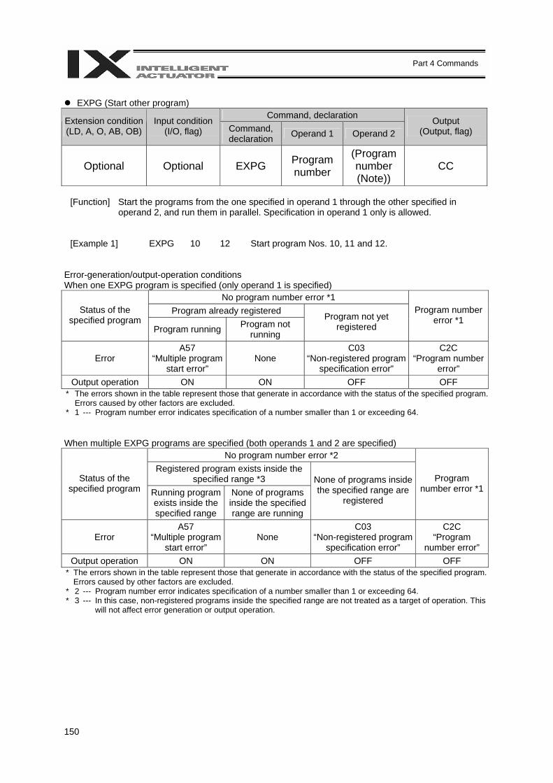
150
Part 4 Commands
EXPG (Start other program)
Command, declaration Extension condition (LD, A, O, AB, OB)
Input condition (I/O, flag) Command,
declaration Operand 1 Operand 2 Output
(Output, flag)
Optional Optional EXPG Program number
(Program number (Note))
CC
[Function] Start the programs from the one specified in operand 1 through the other specified in
operand 2, and run them in parallel. Specification in operand 1 only is allowed.
[Example 1] EXPG 10 12 Start program Nos. 10, 11 and 12.
Error-generation/output-operation conditions When one EXPG program is specified (only operand 1 is specified)
No program number error *1 Program already registered Status of the
specified program Program running Program not
running
Program not yet registered
Program number error *1
Error A57
“Multiple program start error”
None C03
“Non-registered program specification error”
C2C “Program number
error” Output operation ON ON OFF OFF
* The errors shown in the table represent those that generate in accordance with the status of the specified program. Errors caused by other factors are excluded.
* 1 --- Program number error indicates specification of a number smaller than 1 or exceeding 64. When multiple EXPG programs are specified (both operands 1 and 2 are specified)
No program number error *2 Registered program exists inside the
specified range *3 Status of the specified program Running program
exists inside the specified range
None of programs inside the specified range are running
None of programs inside the specified range are
registered
Program number error *1
Error A57
“Multiple program start error”
None C03
“Non-registered program specification error”
C2C “Program
number error” Output operation ON ON OFF OFF
* The errors shown in the table represent those that generate in accordance with the status of the specified program. Errors caused by other factors are excluded.
* 2 --- Program number error indicates specification of a number smaller than 1 or exceeding 64. * 3 --- In this case, non-registered programs inside the specified range are not treated as a target of operation. This
will not affect error generation or output operation.
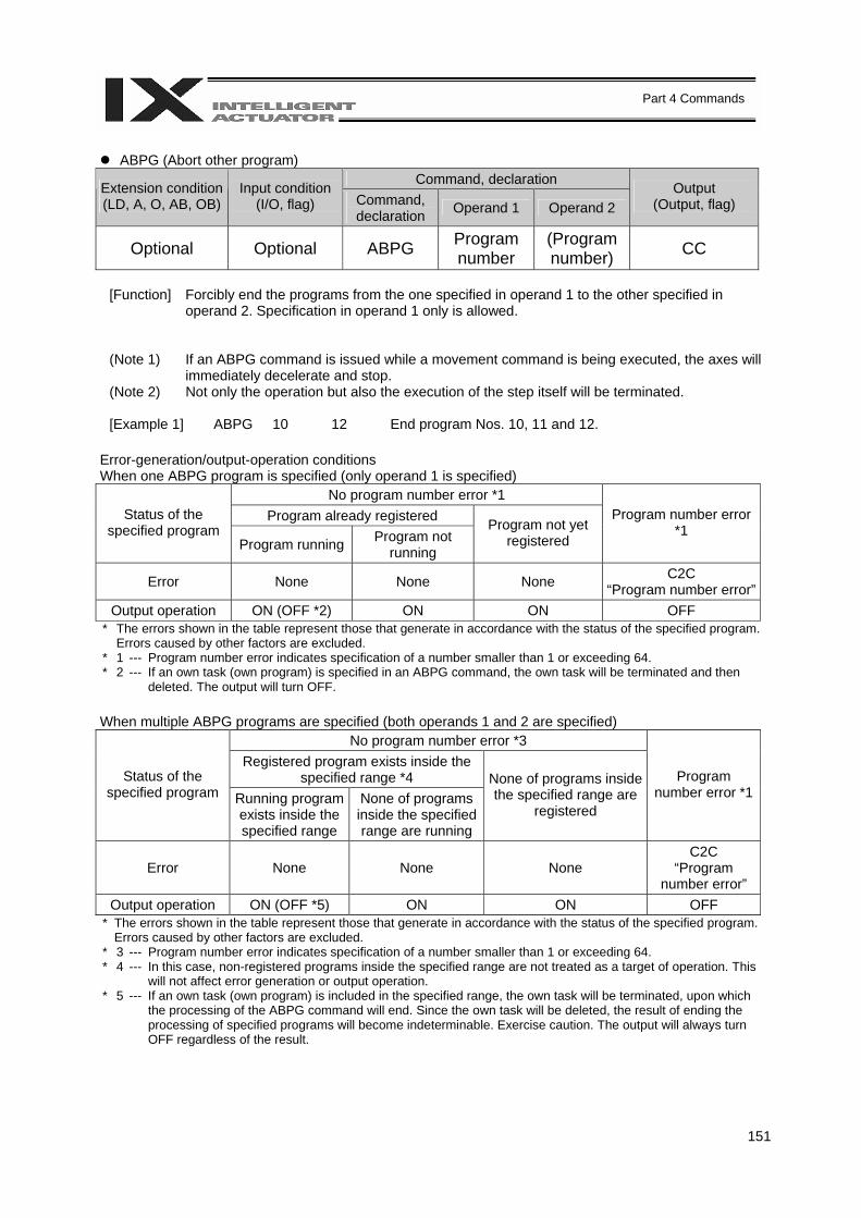
151
Part 4 Commands
ABPG (Abort other program)
Command, declaration Extension condition (LD, A, O, AB, OB)
Input condition (I/O, flag) Command,
declaration Operand 1 Operand 2 Output
(Output, flag)
Optional Optional ABPG Program number
(Program number) CC
[Function] Forcibly end the programs from the one specified in operand 1 to the other specified in
operand 2. Specification in operand 1 only is allowed.
(Note 1) If an ABPG command is issued while a movement command is being executed, the axes will immediately decelerate and stop.
(Note 2) Not only the operation but also the execution of the step itself will be terminated. [Example 1] ABPG 10 12 End program Nos. 10, 11 and 12.
Error-generation/output-operation conditions When one ABPG program is specified (only operand 1 is specified)
No program number error *1 Program already registered Status of the
specified program Program running Program not
running
Program not yet registered
Program number error *1
Error None None None C2C “Program number error”
Output operation ON (OFF *2) ON ON OFF * The errors shown in the table represent those that generate in accordance with the status of the specified program.
Errors caused by other factors are excluded. * 1 --- Program number error indicates specification of a number smaller than 1 or exceeding 64. * 2 --- If an own task (own program) is specified in an ABPG command, the own task will be terminated and then
deleted. The output will turn OFF. When multiple ABPG programs are specified (both operands 1 and 2 are specified)
No program number error *3 Registered program exists inside the
specified range *4 Status of the specified program Running program
exists inside the specified range
None of programs inside the specified range are running
None of programs inside the specified range are
registered
Program number error *1
Error None None None C2C
“Program number error”
Output operation ON (OFF *5) ON ON OFF * The errors shown in the table represent those that generate in accordance with the status of the specified program.
Errors caused by other factors are excluded. * 3 --- Program number error indicates specification of a number smaller than 1 or exceeding 64. * 4 --- In this case, non-registered programs inside the specified range are not treated as a target of operation. This
will not affect error generation or output operation. * 5 --- If an own task (own program) is included in the specified range, the own task will be terminated, upon which
the processing of the ABPG command will end. Since the own task will be deleted, the result of ending the processing of specified programs will become indeterminable. Exercise caution. The output will always turn OFF regardless of the result.
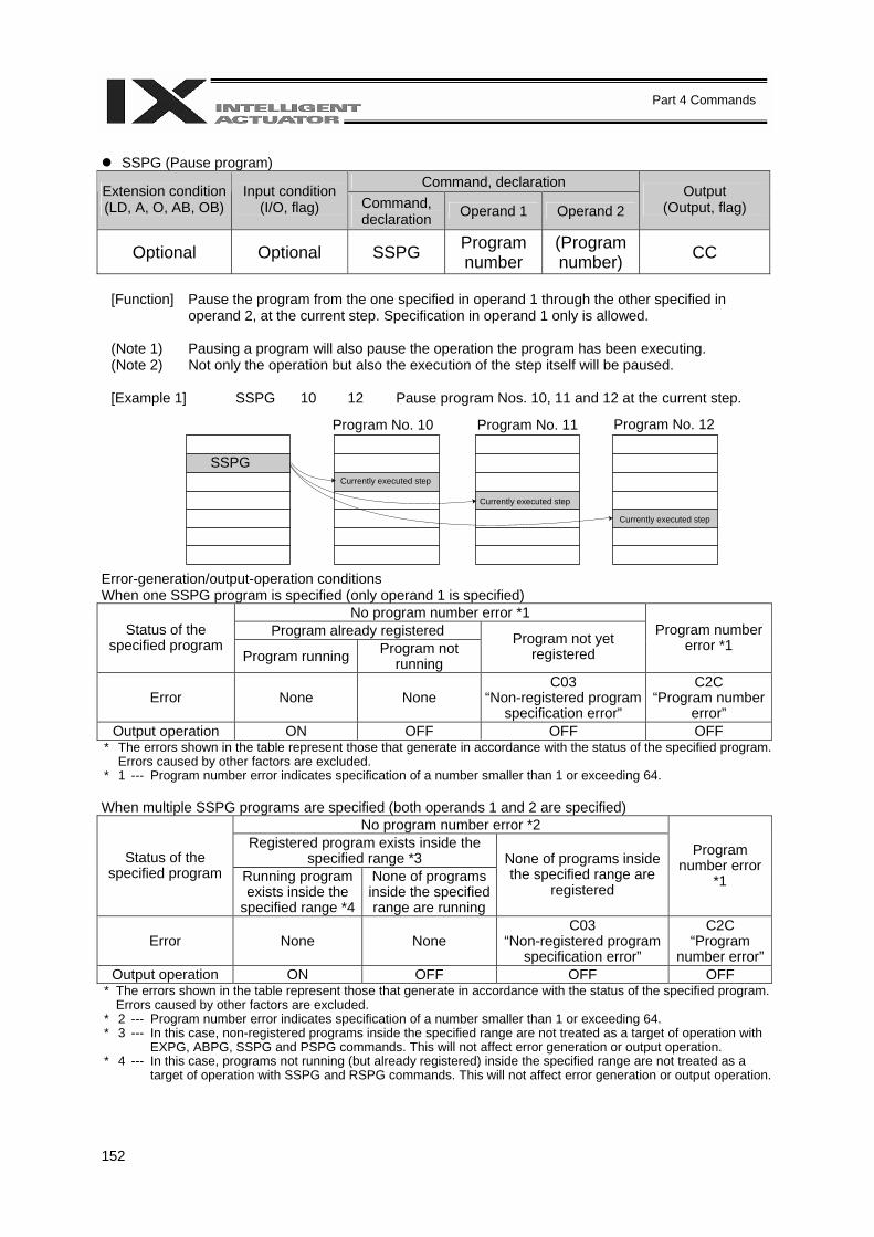
152
Part 4 Commands
SSPG (Pause program)
Command, declaration Extension condition (LD, A, O, AB, OB)
Input condition (I/O, flag) Command,
declaration Operand 1 Operand 2 Output
(Output, flag)
Optional Optional SSPG Program number
(Program number) CC
[Function] Pause the program from the one specified in operand 1 through the other specified in
operand 2, at the current step. Specification in operand 1 only is allowed. (Note 1) Pausing a program will also pause the operation the program has been executing. (Note 2) Not only the operation but also the execution of the step itself will be paused. [Example 1] SSPG 10 12 Pause program Nos. 10, 11 and 12 at the current step.
Error-generation/output-operation conditions When one SSPG program is specified (only operand 1 is specified)
No program number error *1 Program already registered Status of the
specified program Program running Program not
running
Program not yet registered
Program number error *1
Error None None C03
“Non-registered program specification error”
C2C “Program number
error” Output operation ON OFF OFF OFF
* The errors shown in the table represent those that generate in accordance with the status of the specified program. Errors caused by other factors are excluded.
* 1 --- Program number error indicates specification of a number smaller than 1 or exceeding 64. When multiple SSPG programs are specified (both operands 1 and 2 are specified)
No program number error *2 Registered program exists inside the
specified range *3 Status of the specified program Running program
exists inside the specified range *4
None of programs inside the specified range are running
None of programs inside the specified range are
registered
Program number error
*1
Error None None C03
“Non-registered program specification error”
C2C “Program
number error”Output operation ON OFF OFF OFF
* The errors shown in the table represent those that generate in accordance with the status of the specified program. Errors caused by other factors are excluded.
* 2 --- Program number error indicates specification of a number smaller than 1 or exceeding 64. * 3 --- In this case, non-registered programs inside the specified range are not treated as a target of operation with
EXPG, ABPG, SSPG and PSPG commands. This will not affect error generation or output operation. * 4 --- In this case, programs not running (but already registered) inside the specified range are not treated as a
target of operation with SSPG and RSPG commands. This will not affect error generation or output operation.
Program No. 10 Program No. 11 Program No. 12
Currently executed step
Currently executed step
Currently executed step
SSPG
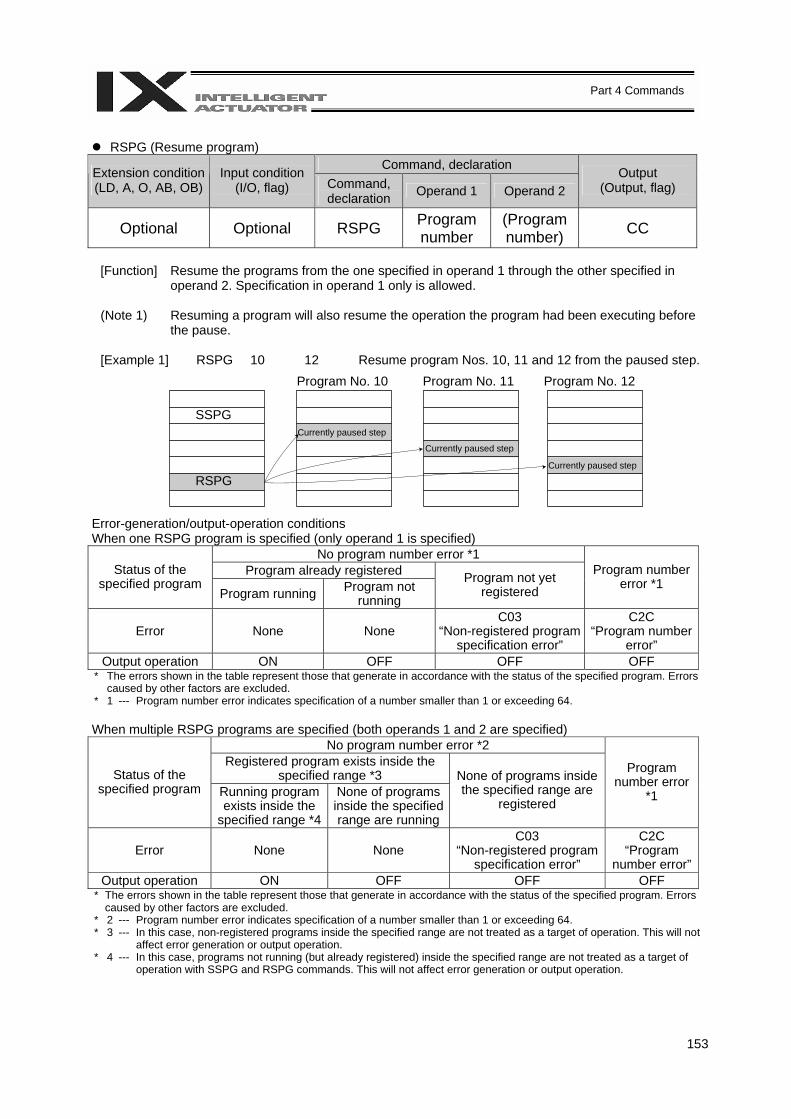
153
Part 4 Commands
RSPG (Resume program)
Command, declaration Extension condition (LD, A, O, AB, OB)
Input condition (I/O, flag) Command,
declaration Operand 1 Operand 2 Output
(Output, flag)
Optional Optional RSPG Program number
(Program number) CC
[Function] Resume the programs from the one specified in operand 1 through the other specified in
operand 2. Specification in operand 1 only is allowed. (Note 1) Resuming a program will also resume the operation the program had been executing before
the pause. [Example 1] RSPG 10 12 Resume program Nos. 10, 11 and 12 from the paused step.
Error-generation/output-operation conditions When one RSPG program is specified (only operand 1 is specified)
No program number error *1 Program already registered Status of the
specified program Program running Program not
running
Program not yet registered
Program number error *1
Error None None C03
“Non-registered program specification error”
C2C “Program number
error” Output operation ON OFF OFF OFF
* The errors shown in the table represent those that generate in accordance with the status of the specified program. Errors caused by other factors are excluded.
* 1 --- Program number error indicates specification of a number smaller than 1 or exceeding 64. When multiple RSPG programs are specified (both operands 1 and 2 are specified)
No program number error *2 Registered program exists inside the
specified range *3 Status of the specified program Running program
exists inside the specified range *4
None of programs inside the specified range are running
None of programs inside the specified range are
registered
Program number error
*1
Error None None C03
“Non-registered program specification error”
C2C “Program
number error”Output operation ON OFF OFF OFF
* The errors shown in the table represent those that generate in accordance with the status of the specified program. Errors caused by other factors are excluded.
* 2 --- Program number error indicates specification of a number smaller than 1 or exceeding 64. * 3 --- In this case, non-registered programs inside the specified range are not treated as a target of operation. This will not
affect error generation or output operation. * 4 --- In this case, programs not running (but already registered) inside the specified range are not treated as a target of
operation with SSPG and RSPG commands. This will not affect error generation or output operation.
Program No. 10 Program No. 11 Program No. 12
SSPG
RSPG
Currently paused step
Currently paused step
Currently paused step
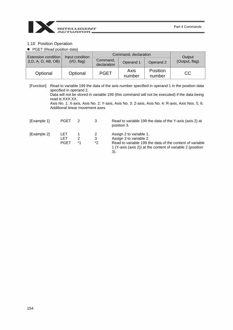
154
Part 4 Commands
1.10 Position Operation
PGET (Read position data) Command, declaration Extension condition
(LD, A, O, AB, OB) Input condition
(I/O, flag) Command, declaration Operand 1 Operand 2
Output (Output, flag)
Optional Optional PGET Axis number
Position number CC
[Function] Read to variable 199 the data of the axis number specified in operand 1 in the position data
specified in operand 2. Data will not be stored in variable 199 (this command will not be executed) if the data being read is XXX.XX. Axis No. 1: X-axis, Axis No. 2: Y-axis, Axis No. 3: Z-axis, Axis No. 4: R-axis, Axis Nos. 5, 6: Additional linear movement axes
[Example 1] PGET 2 3 Read to variable 199 the data of the Y-axis (axis 2) at position 3.
[Example 2] LET 1 2 Assign 2 to variable 1. LET 2 3 Assign 3 to variable 2. PGET *1 *2 Read to variable 199 the data of the content of variable
1 (Y-axis (axis 2)) at the content of variable 2 (position 3).
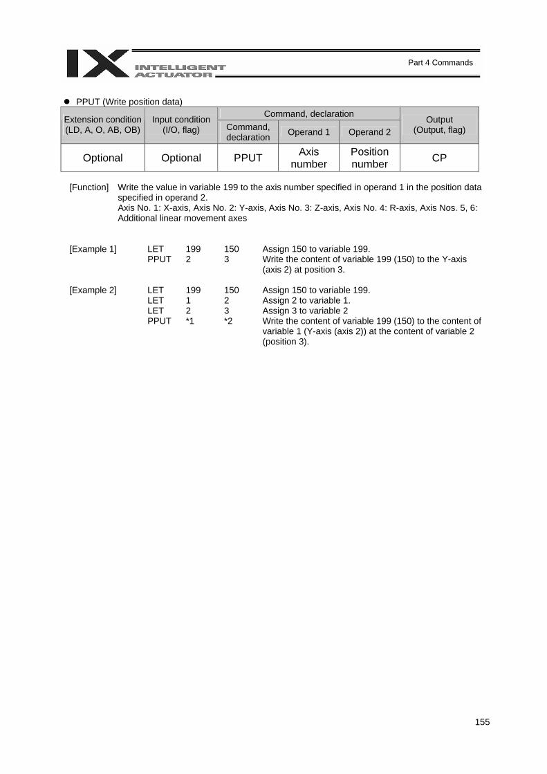
155
Part 4 Commands
PPUT (Write position data)
Command, declaration Extension condition (LD, A, O, AB, OB)
Input condition (I/O, flag) Command,
declaration Operand 1 Operand 2 Output
(Output, flag)
Optional Optional PPUT Axis number
Position number CP
[Function] Write the value in variable 199 to the axis number specified in operand 1 in the position data
specified in operand 2. Axis No. 1: X-axis, Axis No. 2: Y-axis, Axis No. 3: Z-axis, Axis No. 4: R-axis, Axis Nos. 5, 6: Additional linear movement axes
[Example 1] LET 199 150 Assign 150 to variable 199. PPUT 2 3 Write the content of variable 199 (150) to the Y-axis
(axis 2) at position 3. [Example 2] LET 199 150 Assign 150 to variable 199. LET 1 2 Assign 2 to variable 1. LET 2 3 Assign 3 to variable 2 PPUT *1 *2 Write the content of variable 199 (150) to the content of
variable 1 (Y-axis (axis 2)) at the content of variable 2 (position 3).
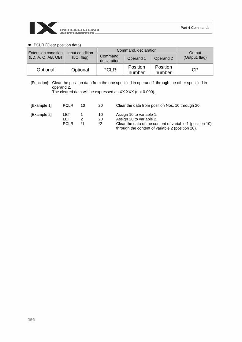
156
Part 4 Commands
PCLR (Clear position data)
Command, declaration Extension condition (LD, A, O, AB, OB)
Input condition (I/O, flag) Command,
declaration Operand 1 Operand 2 Output
(Output, flag)
Optional Optional PCLR Position number
Position number CP
[Function] Clear the position data from the one specified in operand 1 through the other specified in
operand 2. The cleared data will be expressed as XX.XXX (not 0.000).
[Example 1] PCLR 10 20 Clear the data from position Nos. 10 through 20. [Example 2] LET 1 10 Assign 10 to variable 1. LET 2 20 Assign 20 to variable 2. PCLR *1 *2 Clear the data of the content of variable 1 (position 10)
through the content of variable 2 (position 20).
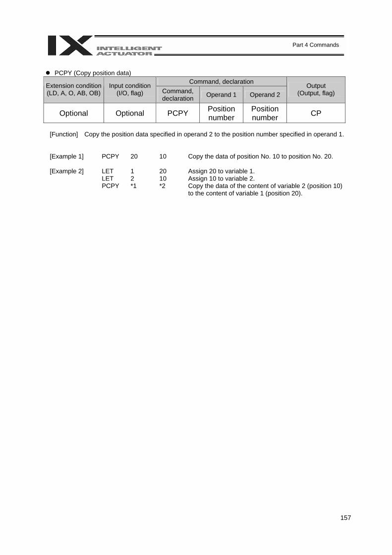
157
Part 4 Commands
PCPY (Copy position data)
Command, declaration Extension condition (LD, A, O, AB, OB)
Input condition (I/O, flag) Command,
declaration Operand 1 Operand 2 Output
(Output, flag)
Optional Optional PCPY Position number
Position number CP
[Function] Copy the position data specified in operand 2 to the position number specified in operand 1.
[Example 1] PCPY 20 10 Copy the data of position No. 10 to position No. 20. [Example 2] LET 1 20 Assign 20 to variable 1. LET 2 10 Assign 10 to variable 2. PCPY *1 *2 Copy the data of the content of variable 2 (position 10)
to the content of variable 1 (position 20).
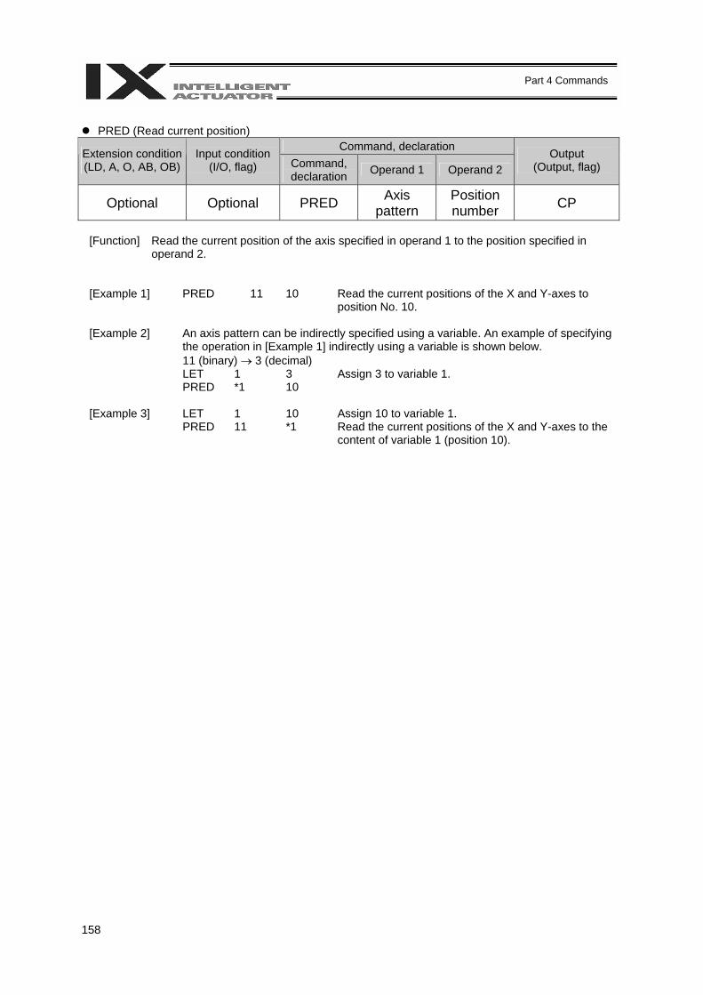
158
Part 4 Commands
PRED (Read current position)
Command, declaration Extension condition (LD, A, O, AB, OB)
Input condition (I/O, flag) Command,
declaration Operand 1 Operand 2 Output
(Output, flag)
Optional Optional PRED Axis pattern
Position number CP
[Function] Read the current position of the axis specified in operand 1 to the position specified in
operand 2.
[Example 1] PRED 11 10 Read the current positions of the X and Y-axes to position No. 10.
[Example 2] An axis pattern can be indirectly specified using a variable. An example of specifying the operation in [Example 1] indirectly using a variable is shown below. 11 (binary) → 3 (decimal)
LET 1 3 Assign 3 to variable 1. PRED *1 10 [Example 3] LET 1 10 Assign 10 to variable 1. PRED 11 *1 Read the current positions of the X and Y-axes to the
content of variable 1 (position 10).
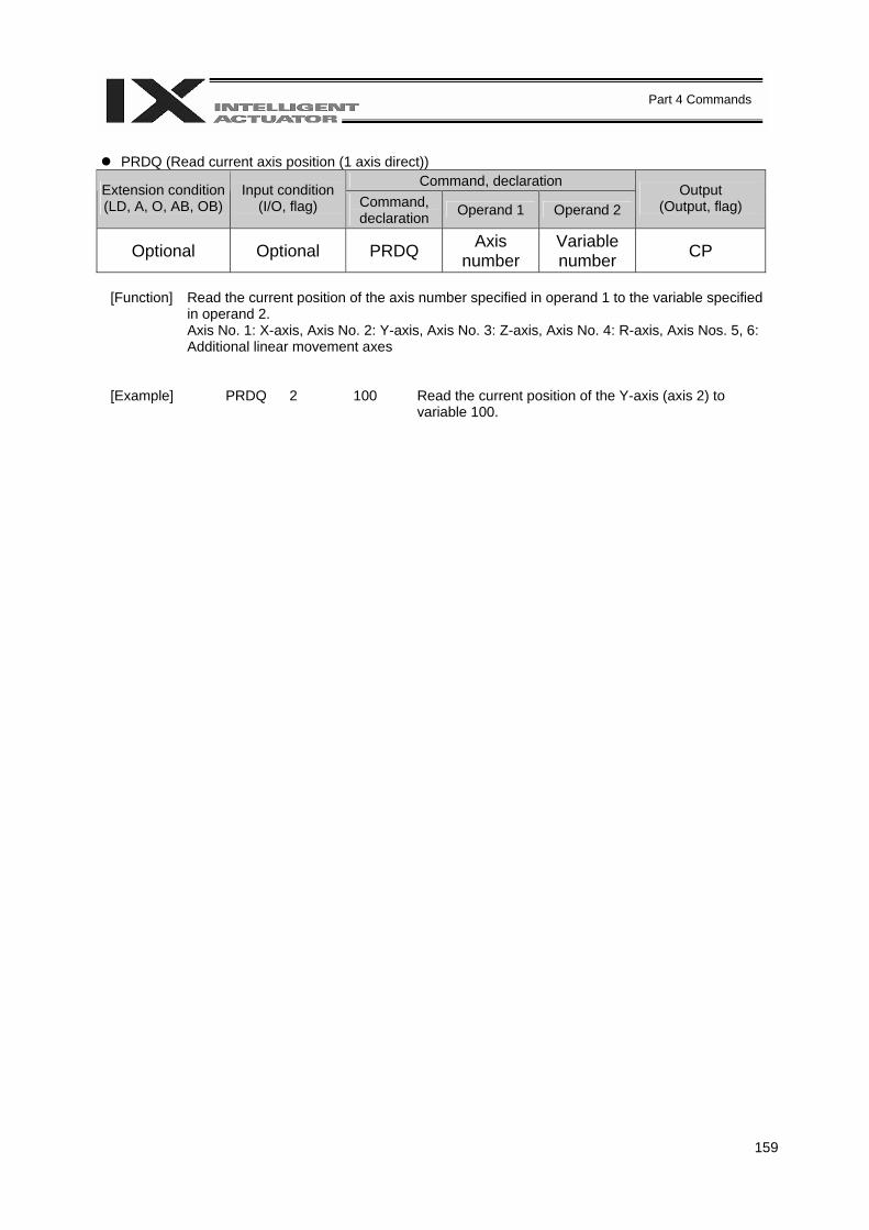
159
Part 4 Commands
PRDQ (Read current axis position (1 axis direct))
Command, declaration Extension condition (LD, A, O, AB, OB)
Input condition (I/O, flag) Command,
declaration Operand 1 Operand 2 Output
(Output, flag)
Optional Optional PRDQ Axis number
Variable number CP
[Function] Read the current position of the axis number specified in operand 1 to the variable specified
in operand 2. Axis No. 1: X-axis, Axis No. 2: Y-axis, Axis No. 3: Z-axis, Axis No. 4: R-axis, Axis Nos. 5, 6: Additional linear movement axes
[Example] PRDQ 2 100 Read the current position of the Y-axis (axis 2) to variable 100.
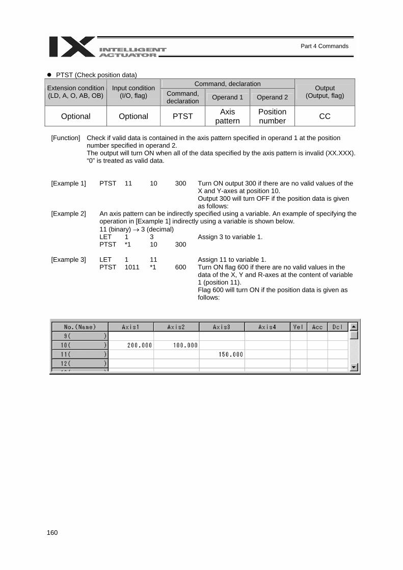
160
Part 4 Commands
PTST (Check position data)
Command, declaration Extension condition (LD, A, O, AB, OB)
Input condition (I/O, flag) Command,
declaration Operand 1 Operand 2 Output
(Output, flag)
Optional Optional PTST Axis pattern
Position number CC
[Function] Check if valid data is contained in the axis pattern specified in operand 1 at the position
number specified in operand 2. The output will turn ON when all of the data specified by the axis pattern is invalid (XX.XXX). “0” is treated as valid data.
[Example 1] PTST 11 10 300 Turn ON output 300 if there are no valid values of the X and Y-axes at position 10. Output 300 will turn OFF if the position data is given as follows:
[Example 2] An axis pattern can be indirectly specified using a variable. An example of specifying the operation in [Example 1] indirectly using a variable is shown below. 11 (binary) → 3 (decimal)
LET 1 3 Assign 3 to variable 1. PTST *1 10 300 [Example 3] LET 1 11 Assign 11 to variable 1. PTST 1011 *1 600 Turn ON flag 600 if there are no valid values in the
data of the X, Y and R-axes at the content of variable 1 (position 11). Flag 600 will turn ON if the position data is given as follows:

161
Part 4 Commands
PVEL (Assign speed data)
Command, declaration Extension condition (LD, A, O, AB, OB)
Input condition (I/O, flag) Command,
declaration Operand 1 Operand 2 Output
(Output, flag)
Optional Optional PVEL Speed Position number CP
[Function] Write the SCARA CP operation speed/linear movement axis speed specified in operand 1,
to the position number specified in operand 2. The unit of operand 1 is mm/sec. (Note) If a negative value is written with a PVEL command, an alarm will generate when that
position is specified in a movement operation, etc. Exercise caution.
[Example 1] PVEL 100 10 Write speed 100 mm/s to position No. 10. [Example 2] LET 1 100 Assign 100 to variable 1. LET 2 10 Assign 10 to variable 2. PVEL *1 *2 Write the content of variable 1 (speed 100 mm/s) to the
content of variable 2 (position 10).

162
Part 4 Commands
PACC (Assign acceleration data)
Command, declaration Extension condition (LD, A, O, AB, OB)
Input condition (I/O, flag) Command,
declaration Operand 1 Operand 2 Output
(Output, flag)
Optional Optional PACC Acceleration Position number CP
[Function] Write the SCARA CP operation acceleration/linear movement axis acceleration specified in
operand 1, to the position number specified in operand 2. The acceleration in operand 1 is set in G and may include up to two decimal places.
(Note) Range check is not performed for a PACC command.
[Example 1] PACC 0.3 10 Write acceleration 0.3 G to position No. 10. [Example 2] LET 100 0.3 Assign 0.3 to variable 100. LET 2 10 Assign 10 to variable 2. PACC *100 *2 Write the content of variable 100 (acceleration 0.3 G) to
the content of variable 2 (position 10).
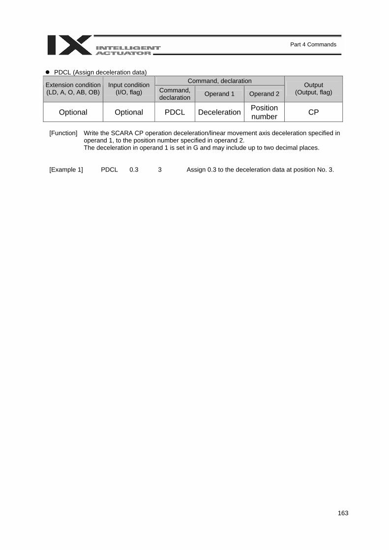
163
Part 4 Commands
PDCL (Assign deceleration data)
Command, declaration Extension condition (LD, A, O, AB, OB)
Input condition (I/O, flag) Command,
declaration Operand 1 Operand 2 Output
(Output, flag)
Optional Optional PDCL Deceleration Position number CP
[Function] Write the SCARA CP operation deceleration/linear movement axis deceleration specified in
operand 1, to the position number specified in operand 2. The deceleration in operand 1 is set in G and may include up to two decimal places.
[Example 1] PDCL 0.3 3 Assign 0.3 to the deceleration data at position No. 3.
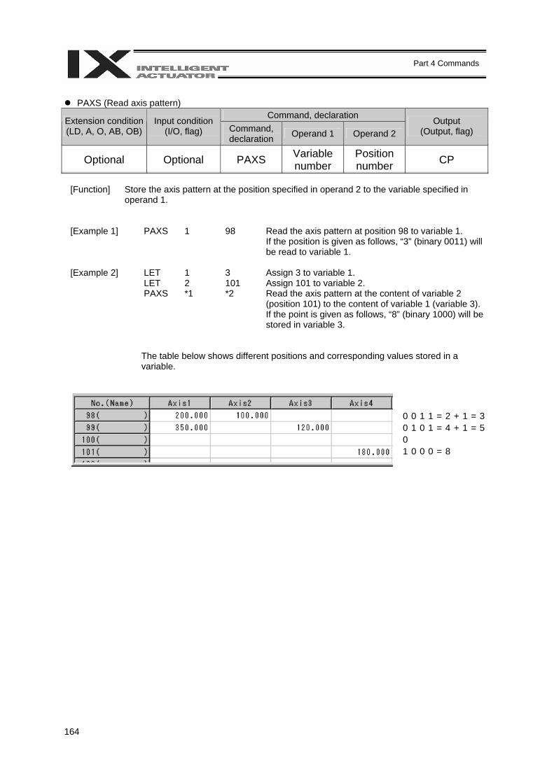
164
Part 4 Commands
PAXS (Read axis pattern)
Command, declaration Extension condition (LD, A, O, AB, OB)
Input condition (I/O, flag) Command,
declaration Operand 1 Operand 2 Output
(Output, flag)
Optional Optional PAXS Variable number
Position number CP
[Function] Store the axis pattern at the position specified in operand 2 to the variable specified in
operand 1.
[Example 1] PAXS 1 98 Read the axis pattern at position 98 to variable 1. If the position is given as follows, “3” (binary 0011) will be read to variable 1.
[Example 2] LET 1 3 Assign 3 to variable 1. LET 2 101 Assign 101 to variable 2. PAXS *1 *2 Read the axis pattern at the content of variable 2
(position 101) to the content of variable 1 (variable 3). If the point is given as follows, “8” (binary 1000) will be stored in variable 3.
The table below shows different positions and corresponding values stored in a variable.
0 0 1 1 = 2 + 1 = 3 0 1 0 1 = 4 + 1 = 5 0 1 0 0 0 = 8
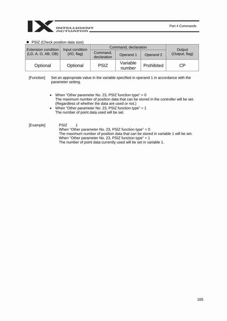
165
Part 4 Commands
PSIZ (Check position data size)
Command, declaration Extension condition (LD, A, O, AB, OB)
Input condition (I/O, flag) Command,
declaration Operand 1 Operand 2 Output
(Output, flag)
Optional Optional PSIZ Variable number Prohibited CP
[Function] Set an appropriate value in the variable specified in operand 1 in accordance with the
parameter setting.
• When “Other parameter No. 23, PSIZ function type” = 0 The maximum number of position data that can be stored in the controller will be set. (Regardless of whether the data are used or not.)
• When “Other parameter No. 23, PSIZ function type” = 1 The number of point data used will be set.
[Example] PSIZ 1 When “Other parameter No. 23, PSIZ function type” = 0
The maximum number of position data that can be stored in variable 1 will be set. When “Other parameter No. 23, PSIZ function type” = 1 The number of point data currently used will be set in variable 1.
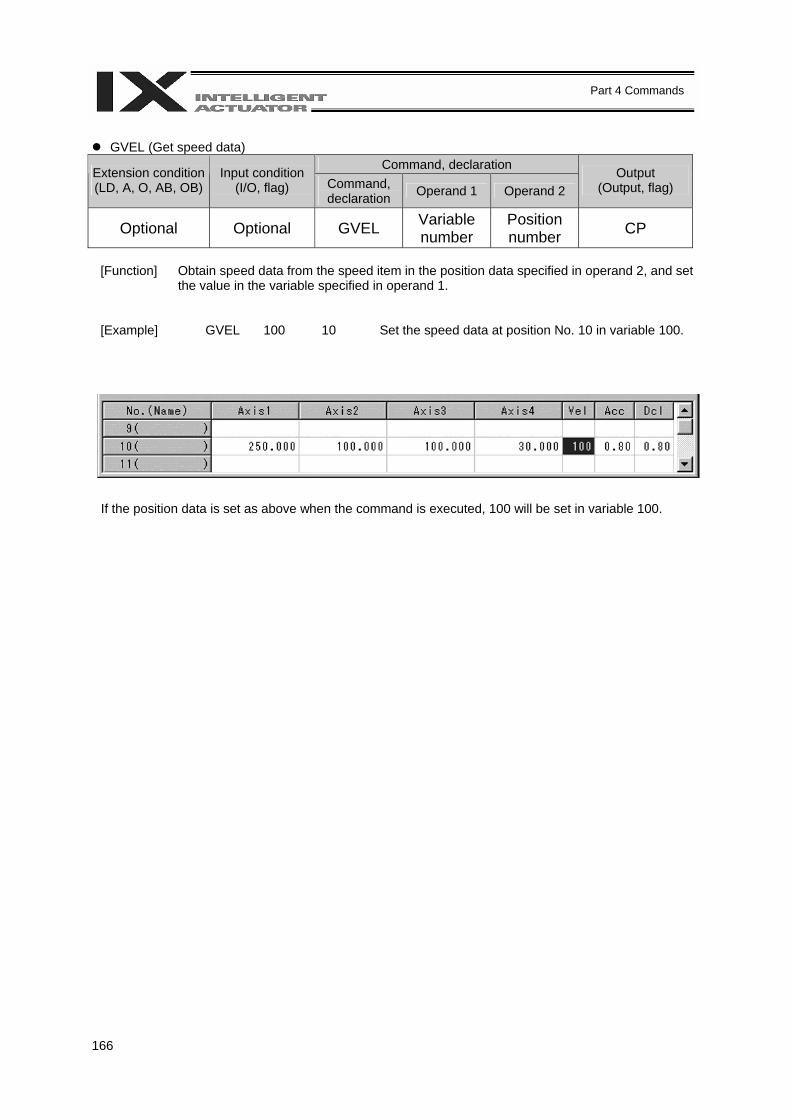
166
Part 4 Commands
GVEL (Get speed data)
Command, declaration Extension condition (LD, A, O, AB, OB)
Input condition (I/O, flag) Command,
declaration Operand 1 Operand 2 Output
(Output, flag)
Optional Optional GVEL Variable number
Position number CP
[Function] Obtain speed data from the speed item in the position data specified in operand 2, and set
the value in the variable specified in operand 1.
[Example] GVEL 100 10 Set the speed data at position No. 10 in variable 100.
If the position data is set as above when the command is executed, 100 will be set in variable 100.
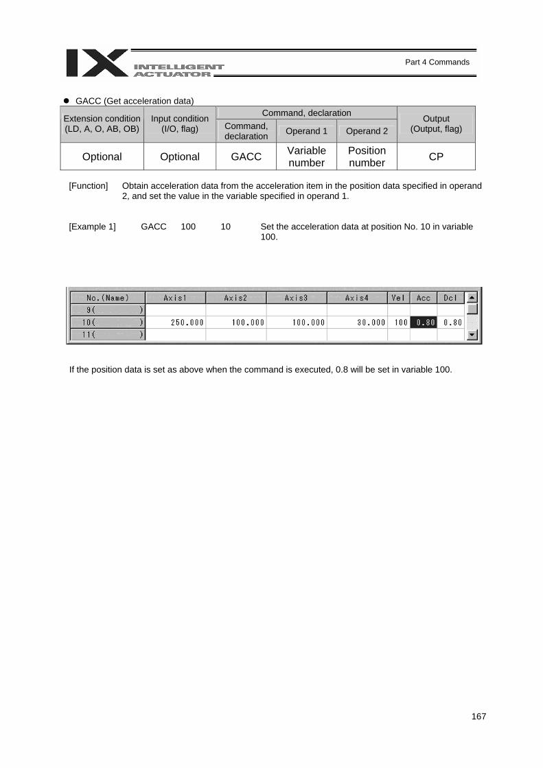
167
Part 4 Commands
GACC (Get acceleration data)
Command, declaration Extension condition (LD, A, O, AB, OB)
Input condition (I/O, flag) Command,
declaration Operand 1 Operand 2 Output
(Output, flag)
Optional Optional GACC Variable number
Position number CP
[Function] Obtain acceleration data from the acceleration item in the position data specified in operand
2, and set the value in the variable specified in operand 1.
[Example 1] GACC 100 10 Set the acceleration data at position No. 10 in variable 100.
If the position data is set as above when the command is executed, 0.8 will be set in variable 100.
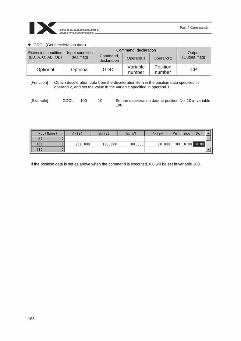
168
Part 4 Commands
GDCL (Get deceleration data)
Command, declaration Extension condition (LD, A, O, AB, OB)
Input condition (I/O, flag) Command,
declaration Operand 1 Operand 2 Output
(Output, flag)
Optional Optional GDCL Variable number
Position number CP
[Function] Obtain deceleration data from the deceleration item in the position data specified in
operand 2, and set the value in the variable specified in operand 1.
[Example] GDCL 100 10 Set the deceleration data at position No. 10 in variable 100.
If the position data is set as above when the command is executed, 0.8 will be set in variable 100.
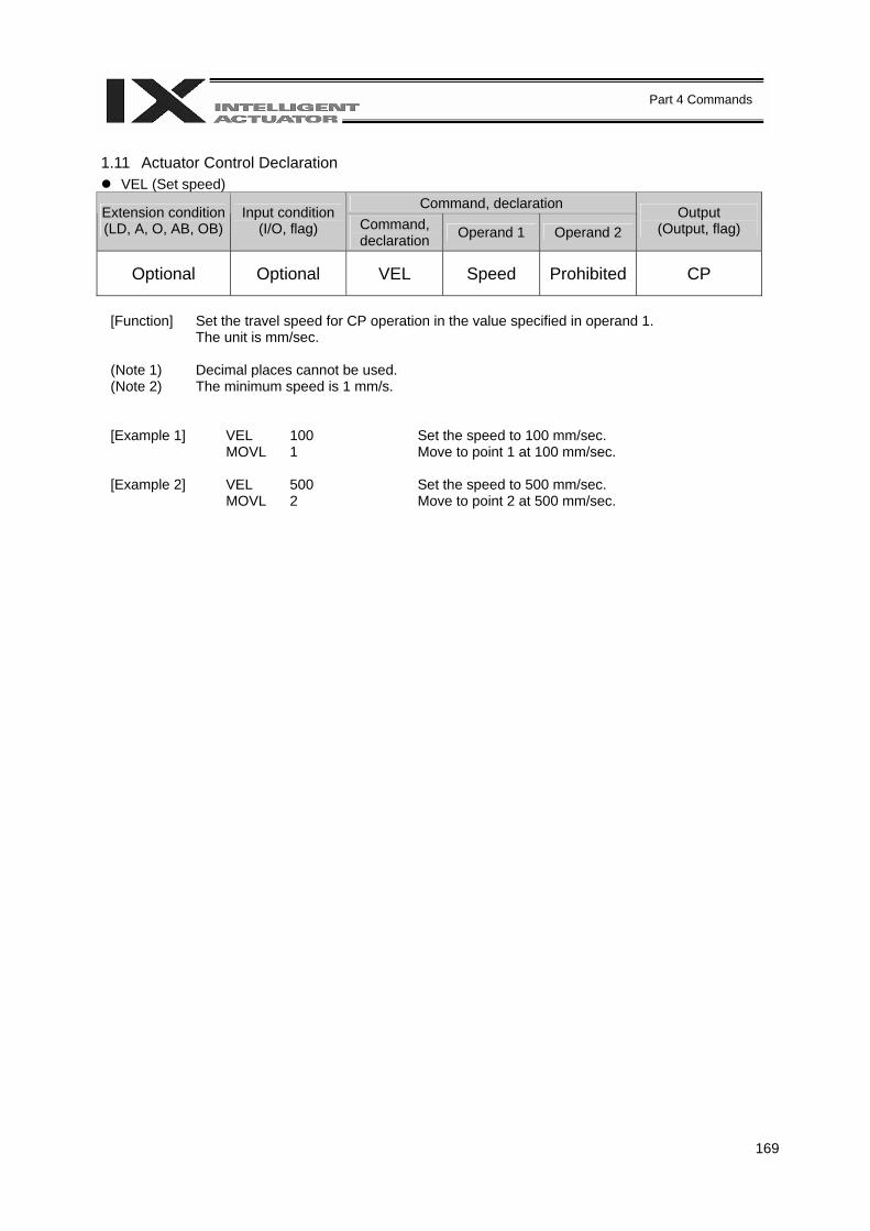
169
Part 4 Commands
1.11 Actuator Control Declaration
VEL (Set speed) Command, declaration Extension condition
(LD, A, O, AB, OB) Input condition
(I/O, flag) Command, declaration Operand 1 Operand 2
Output (Output, flag)
Optional Optional VEL Speed Prohibited CP
[Function] Set the travel speed for CP operation in the value specified in operand 1.
The unit is mm/sec. (Note 1) Decimal places cannot be used. (Note 2) The minimum speed is 1 mm/s.
[Example 1] VEL 100 Set the speed to 100 mm/sec. MOVL 1 Move to point 1 at 100 mm/sec. [Example 2] VEL 500 Set the speed to 500 mm/sec. MOVL 2 Move to point 2 at 500 mm/sec.
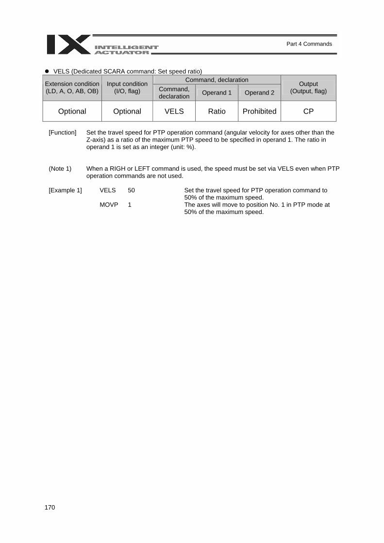
170
Part 4 Commands
VELS (Dedicated SCARA command: Set speed ratio)
Command, declaration Extension condition (LD, A, O, AB, OB)
Input condition (I/O, flag) Command,
declaration Operand 1 Operand 2 Output
(Output, flag)
Optional Optional VELS Ratio Prohibited CP
[Function] Set the travel speed for PTP operation command (angular velocity for axes other than the
Z-axis) as a ratio of the maximum PTP speed to be specified in operand 1. The ratio in operand 1 is set as an integer (unit: %).
(Note 1) When a RIGH or LEFT command is used, the speed must be set via VELS even when PTP operation commands are not used.
[Example 1] VELS 50 Set the travel speed for PTP operation command to
50% of the maximum speed. MOVP 1 The axes will move to position No. 1 in PTP mode at
50% of the maximum speed.
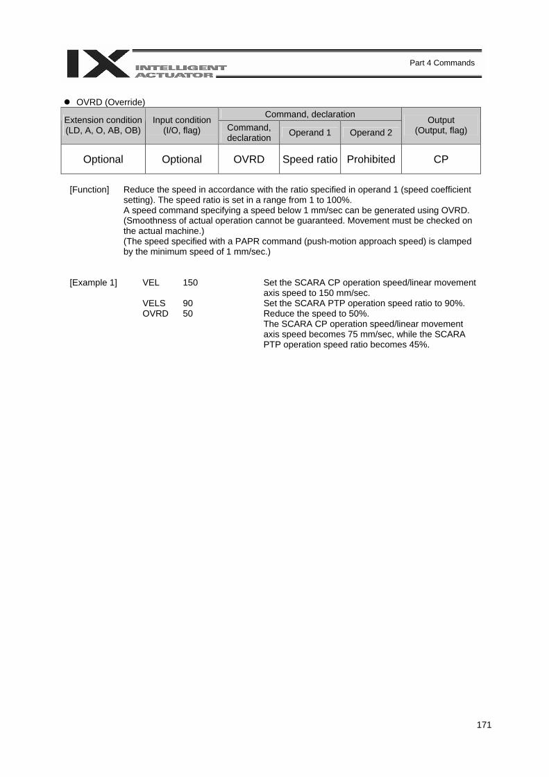
171
Part 4 Commands
OVRD (Override)
Command, declaration Extension condition (LD, A, O, AB, OB)
Input condition (I/O, flag) Command,
declaration Operand 1 Operand 2 Output
(Output, flag)
Optional Optional OVRD Speed ratio Prohibited CP
[Function] Reduce the speed in accordance with the ratio specified in operand 1 (speed coefficient
setting). The speed ratio is set in a range from 1 to 100%. A speed command specifying a speed below 1 mm/sec can be generated using OVRD. (Smoothness of actual operation cannot be guaranteed. Movement must be checked on the actual machine.) (The speed specified with a PAPR command (push-motion approach speed) is clamped by the minimum speed of 1 mm/sec.)
[Example 1] VEL 150 Set the SCARA CP operation speed/linear movement axis speed to 150 mm/sec.
VELS 90 Set the SCARA PTP operation speed ratio to 90%. OVRD 50 Reduce the speed to 50%.
The SCARA CP operation speed/linear movement axis speed becomes 75 mm/sec, while the SCARA PTP operation speed ratio becomes 45%.
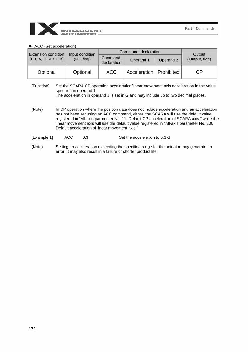
172
Part 4 Commands
ACC (Set acceleration)
Command, declaration Extension condition (LD, A, O, AB, OB)
Input condition (I/O, flag) Command,
declaration Operand 1 Operand 2 Output
(Output, flag)
Optional Optional ACC Acceleration Prohibited CP
[Function] Set the SCARA CP operation acceleration/linear movement axis acceleration in the value
specified in operand 1. The acceleration in operand 1 is set in G and may include up to two decimal places.
(Note) In CP operation where the position data does not include acceleration and an acceleration has not been set using an ACC command, either, the SCARA will use the default value registered in “All-axis parameter No. 11, Default CP acceleration of SCARA axis,” while the linear movement axis will use the default value registered in “All-axis parameter No. 200, Default acceleration of linear movement axis.”
[Example 1] ACC 0.3 Set the acceleration to 0.3 G.
(Note) Setting an acceleration exceeding the specified range for the actuator may generate an
error. It may also result in a failure or shorter product life.
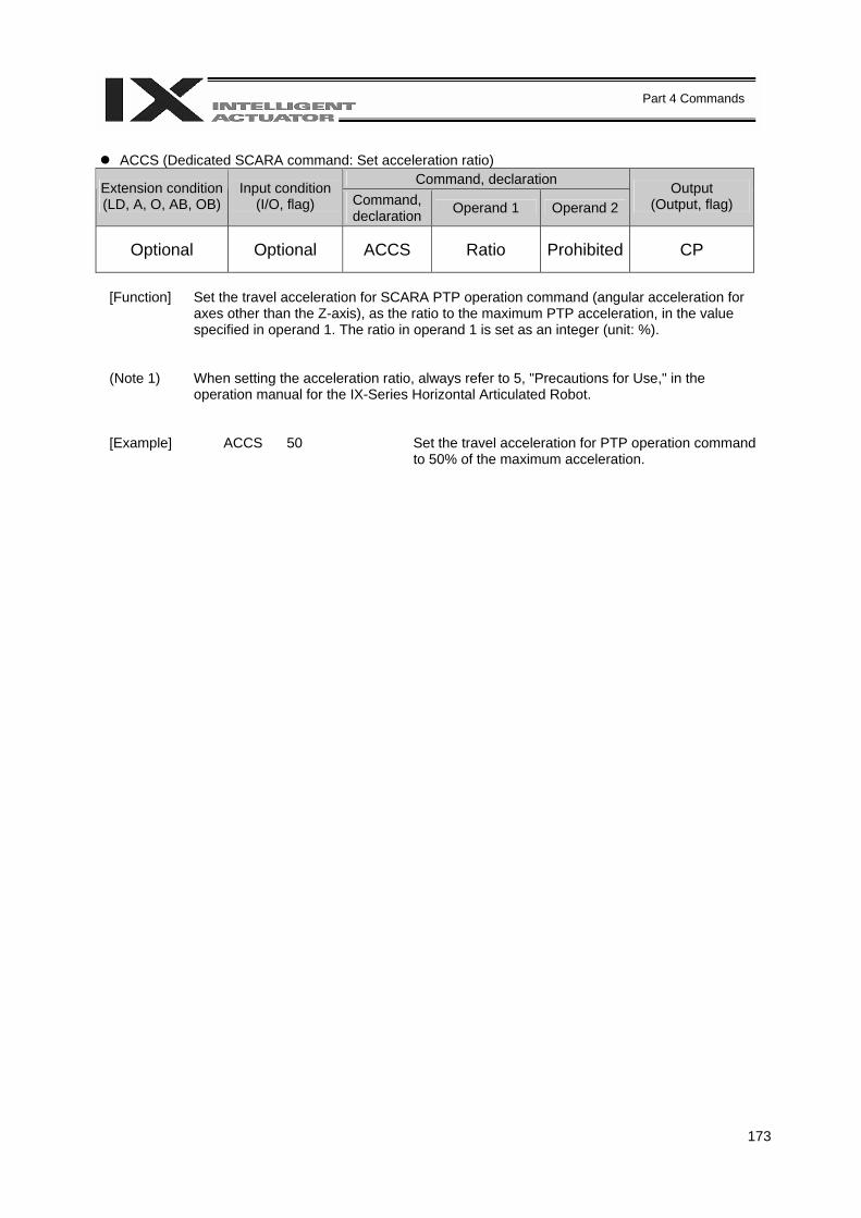
173
Part 4 Commands
ACCS (Dedicated SCARA command: Set acceleration ratio)
Command, declaration Extension condition (LD, A, O, AB, OB)
Input condition (I/O, flag) Command,
declaration Operand 1 Operand 2 Output
(Output, flag)
Optional Optional ACCS Ratio Prohibited CP
[Function] Set the travel acceleration for SCARA PTP operation command (angular acceleration for
axes other than the Z-axis), as the ratio to the maximum PTP acceleration, in the value specified in operand 1. The ratio in operand 1 is set as an integer (unit: %).
(Note 1) When setting the acceleration ratio, always refer to 5, "Precautions for Use," in the operation manual for the IX-Series Horizontal Articulated Robot.
[Example] ACCS 50 Set the travel acceleration for PTP operation command
to 50% of the maximum acceleration.

174
Part 4 Commands
DCL (Set deceleration)
Command, declaration Extension condition (LD, A, O, AB, OB)
Input condition (I/O, flag) Command,
declaration Operand 1 Operand 2 Output
(Output, flag)
Optional Optional DCL Deceleration Prohibited CP
[Function] Set the SCARA CP operation deceleration/linear movement axis deceleration in the value
specified in operand 1. The deceleration in operand 1 is set in G and may include up to two decimal places.
(Note) In CP operation where the position data does not include deceleration and a deceleration has not been set using a DCL command, either, the SCARA will use the default value registered in “All-axis parameter No. 12, Default CP deceleration of SCARA axis,” while the linear movement axis will use the default value registered in “All-axis parameter No. 201, Default deceleration of linear movement axis.” A DCL command cannot be used with CIR and ARC commands.
[Example] DCL 0.3 Set the deceleration to 0.3 G.
(Note) Setting a deceleration exceeding the specified range for the actuator may generate an
error. It may also result in a failure or shorter product life.
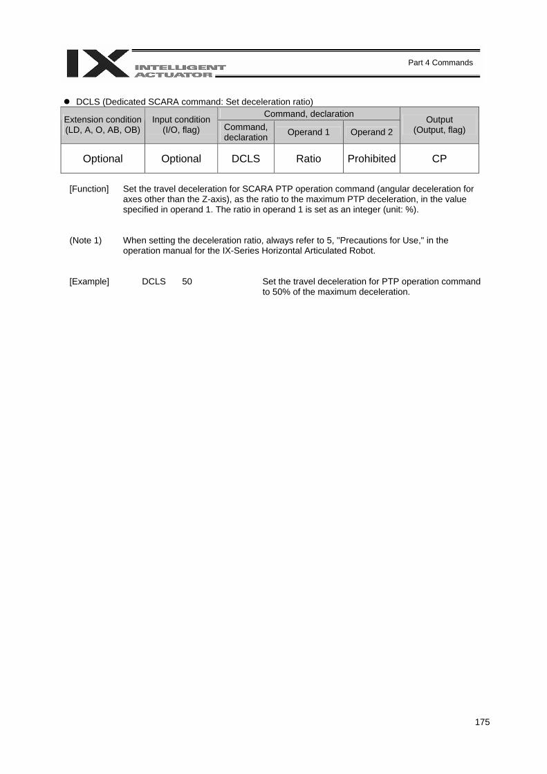
175
Part 4 Commands
DCLS (Dedicated SCARA command: Set deceleration ratio)
Command, declaration Extension condition (LD, A, O, AB, OB)
Input condition (I/O, flag) Command,
declaration Operand 1 Operand 2 Output
(Output, flag)
Optional Optional DCLS Ratio Prohibited CP
[Function] Set the travel deceleration for SCARA PTP operation command (angular deceleration for
axes other than the Z-axis), as the ratio to the maximum PTP deceleration, in the value specified in operand 1. The ratio in operand 1 is set as an integer (unit: %).
(Note 1) When setting the deceleration ratio, always refer to 5, "Precautions for Use," in the operation manual for the IX-Series Horizontal Articulated Robot.
[Example] DCLS 50 Set the travel deceleration for PTP operation command
to 50% of the maximum deceleration.
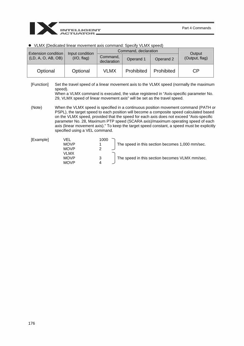
176
Part 4 Commands
VLMX (Dedicated linear movement axis command: Specify VLMX speed)
Command, declaration Extension condition (LD, A, O, AB, OB)
Input condition (I/O, flag) Command,
declaration Operand 1 Operand 2 Output
(Output, flag)
Optional Optional VLMX Prohibited Prohibited CP
[Function] Set the travel speed of a linear movement axis to the VLMX speed (normally the maximum
speed). When a VLMX command is executed, the value registered in “Axis-specific parameter No. 29, VLMX speed of linear movement axis” will be set as the travel speed.
(Note) When the VLMX speed is specified in a continuous position movement command (PATH or
PSPL), the target speed to each position will become a composite speed calculated based on the VLMX speed, provided that the speed for each axis does not exceed “Axis-specific parameter No. 28, Maximum PTP speed (SCARA axis)/maximum operating speed of each axis (linear movement axis).” To keep the target speed constant, a speed must be explicitly specified using a VEL command.
[Example] VEL 1000 MOVP 1 The speed in this section becomes 1,000 mm/sec. MOVP 2 VLMX MOVP 3 The speed in this section becomes VLMX mm/sec. MOVP 4
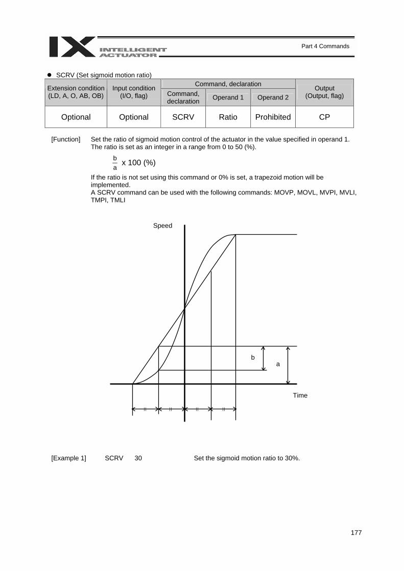
177
Part 4 Commands
SCRV (Set sigmoid motion ratio)
Command, declaration Extension condition (LD, A, O, AB, OB)
Input condition (I/O, flag) Command,
declaration Operand 1 Operand 2 Output
(Output, flag)
Optional Optional SCRV Ratio Prohibited CP
[Function] Set the ratio of sigmoid motion control of the actuator in the value specified in operand 1.
The ratio is set as an integer in a range from 0 to 50 (%).
ab x 100 (%)
If the ratio is not set using this command or 0% is set, a trapezoid motion will be implemented. A SCRV command can be used with the following commands: MOVP, MOVL, MVPI, MVLI, TMPI, TMLI
[Example 1] SCRV 30 Set the sigmoid motion ratio to 30%.
a b
Speed
Time
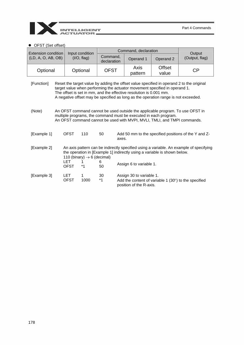
178
Part 4 Commands
OFST (Set offset)
Command, declaration Extension condition (LD, A, O, AB, OB)
Input condition (I/O, flag) Command,
declaration Operand 1 Operand 2 Output
(Output, flag)
Optional Optional OFST Axis pattern
Offset value CP
[Function] Reset the target value by adding the offset value specified in operand 2 to the original
target value when performing the actuator movement specified in operand 1. The offset is set in mm, and the effective resolution is 0.001 mm. A negative offset may be specified as long as the operation range is not exceeded.
(Note) An OFST command cannot be used outside the applicable program. To use OFST in multiple programs, the command must be executed in each program. An OFST command cannot be used with MVPI, MVLI, TMLI, and TMPI commands.
[Example 1] OFST 110 50 Add 50 mm to the specified positions of the Y and Z-axes.
[Example 2] An axis pattern can be indirectly specified using a variable. An example of specifying
the operation in [Example 1] indirectly using a variable is shown below. 110 (binary) → 6 (decimal)
LET 1 6 OFST *1 50 Assign 6 to variable 1.
[Example 3] LET 1 30 Assign 30 to variable 1. OFST 1000 *1 Add the content of variable 1 (30°) to the specified
position of the R-axis.
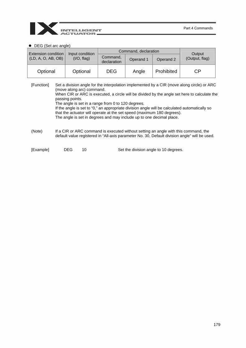
179
Part 4 Commands
DEG (Set arc angle)
Command, declaration Extension condition (LD, A, O, AB, OB)
Input condition (I/O, flag) Command,
declaration Operand 1 Operand 2 Output
(Output, flag)
Optional Optional DEG Angle Prohibited CP
[Function] Set a division angle for the interpolation implemented by a CIR (move along circle) or ARC
(move along arc) command. When CIR or ARC is executed, a circle will be divided by the angle set here to calculate the passing points. The angle is set in a range from 0 to 120 degrees. If the angle is set to “0,” an appropriate division angle will be calculated automatically so that the actuator will operate at the set speed (maximum 180 degrees). The angle is set in degrees and may include up to one decimal place.
(Note) If a CIR or ARC command is executed without setting an angle with this command, the default value registered in “All-axis parameter No. 30, Default division angle” will be used.
[Example] DEG 10 Set the division angle to 10 degrees.
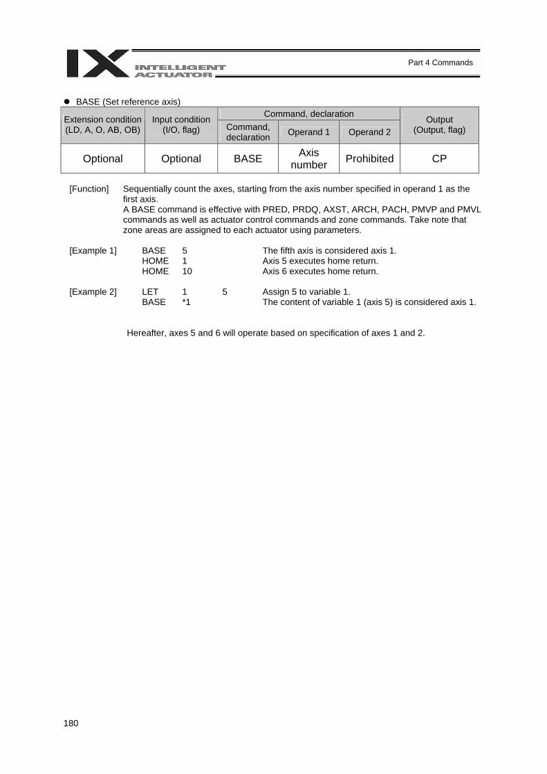
180
Part 4 Commands
BASE (Set reference axis)
Command, declaration Extension condition (LD, A, O, AB, OB)
Input condition (I/O, flag) Command,
declaration Operand 1 Operand 2 Output
(Output, flag)
Optional Optional BASE Axis number Prohibited CP
[Function] Sequentially count the axes, starting from the axis number specified in operand 1 as the
first axis. A BASE command is effective with PRED, PRDQ, AXST, ARCH, PACH, PMVP and PMVL commands as well as actuator control commands and zone commands. Take note that zone areas are assigned to each actuator using parameters.
[Example 1] BASE 5 The fifth axis is considered axis 1. HOME 1 Axis 5 executes home return. HOME 10 Axis 6 executes home return. [Example 2] LET 1 5 Assign 5 to variable 1. BASE *1 The content of variable 1 (axis 5) is considered axis 1.
Hereafter, axes 5 and 6 will operate based on specification of axes 1 and 2.
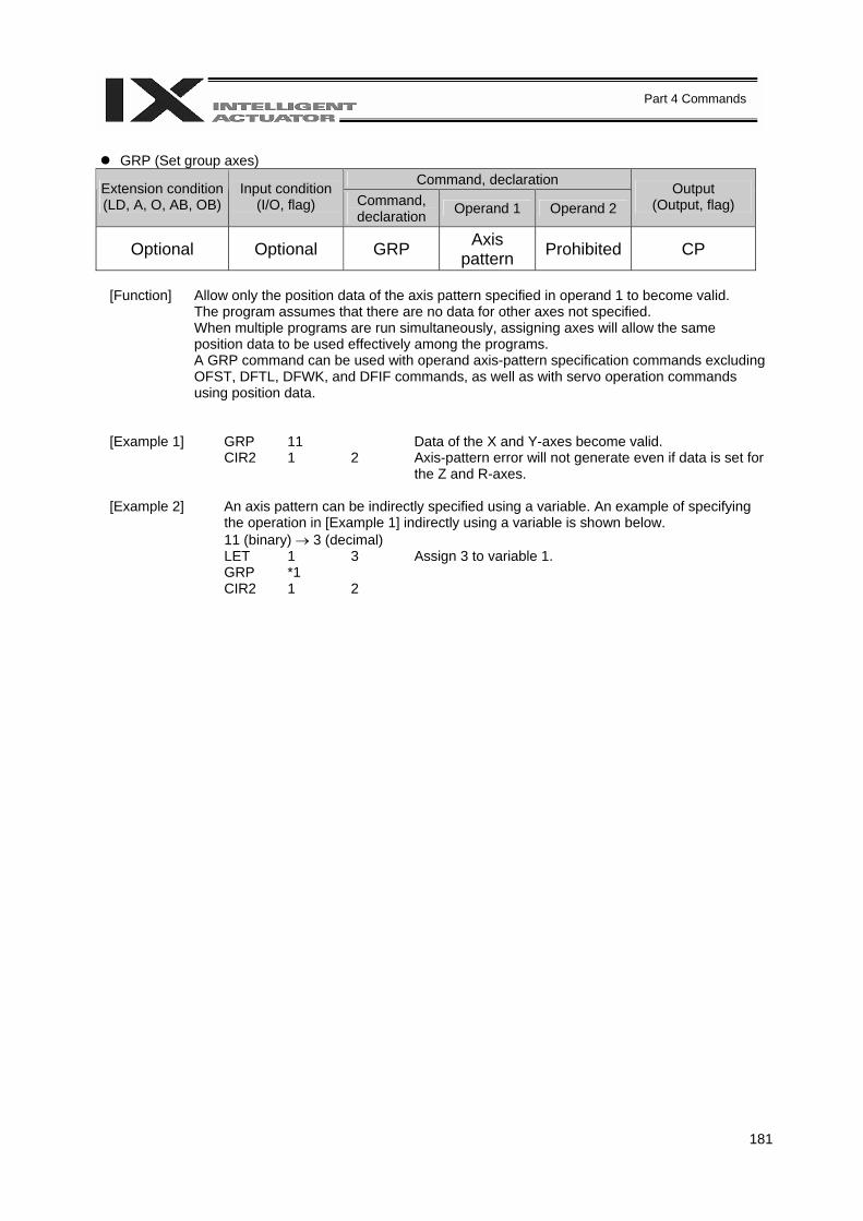
181
Part 4 Commands
GRP (Set group axes)
Command, declaration Extension condition (LD, A, O, AB, OB)
Input condition (I/O, flag) Command,
declaration Operand 1 Operand 2 Output
(Output, flag)
Optional Optional GRP Axis pattern Prohibited CP
[Function] Allow only the position data of the axis pattern specified in operand 1 to become valid.
The program assumes that there are no data for other axes not specified. When multiple programs are run simultaneously, assigning axes will allow the same position data to be used effectively among the programs. A GRP command can be used with operand axis-pattern specification commands excluding OFST, DFTL, DFWK, and DFIF commands, as well as with servo operation commands using position data.
[Example 1] GRP 11 Data of the X and Y-axes become valid. CIR2 1 2 Axis-pattern error will not generate even if data is set for
the Z and R-axes. [Example 2] An axis pattern can be indirectly specified using a variable. An example of specifying
the operation in [Example 1] indirectly using a variable is shown below. 11 (binary) → 3 (decimal)
LET 1 3 Assign 3 to variable 1. GRP *1 CIR2 1 2
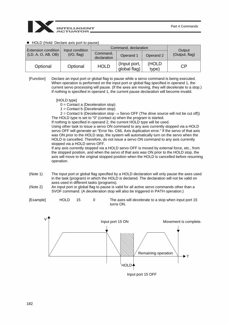
182
Part 4 Commands
HOLD (Hold: Declare axis port to pause)
Command, declaration Extension condition (LD, A, O, AB, OB)
Input condition (I/O, flag) Command,
declaration Operand 1 Operand 2 Output
(Output, flag)
Optional Optional HOLD (Input port, global flag)
(HOLD type) CP
[Function] Declare an input port or global flag to pause while a servo command is being executed.
When operation is performed on the input port or global flag specified in operand 1, the current servo processing will pause. (If the axes are moving, they will decelerate to a stop.) If nothing is specified in operand 1, the current pause declaration will become invalid.
[HOLD type]
0 = Contact a (Deceleration stop) 1 = Contact b (Deceleration stop) 2 = Contact b (Deceleration stop → Servo OFF (The drive source will not be cut off))
The HOLD type is set to “0” (contact a) when the program is started. If nothing is specified in operand 2, the current HOLD type will be used. Using other task to issue a servo ON command to any axis currently stopped via a HOLD servo OFF will generate an “Error No. C66, Axis duplication error.” If the servo of that axis was ON prior to the HOLD stop, the system will automatically turn on the servo when the HOLD is cancelled. Therefore, do not issue a servo ON command to any axis currently stopped via a HOLD servo OFF. If any axis currently stopped via a HOLD servo OFF is moved by external force, etc., from the stopped position, and when the servo of that axis was ON prior to the HOLD stop, the axis will move to the original stopped position when the HOLD is cancelled before resuming operation.
(Note 1) The input port or global flag specified by a HOLD declaration will only pause the axes used in the task (program) in which the HOLD is declared. The declaration will not be valid on axes used in different tasks (programs).
(Note 2) An input port or global flag to pause is valid for all active servo commands other than a SVOF command. (A deceleration stop will also be triggered in PATH operation.)
[Example] HOLD 15 0 The axes will decelerate to a stop when input port 15
turns ON.
Input port 15 ON Movement is complete.
Remaining operation
V
T
HOLD
Input port 15 OFF
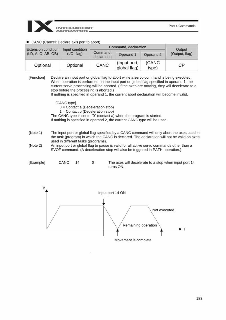
183
Part 4 Commands
CANC (Cancel: Declare axis port to abort)
Command, declaration Extension condition (LD, A, O, AB, OB)
Input condition (I/O, flag) Command,
declaration Operand 1 Operand 2 Output
(Output, flag)
Optional Optional CANC (Input port, global flag)
(CANC type) CP
[Function] Declare an input port or global flag to abort while a servo command is being executed.
When operation is performed on the input port or global flag specified in operand 1, the current servo processing will be aborted. (If the axes are moving, they will decelerate to a stop before the processing is aborted.) If nothing is specified in operand 1, the current abort declaration will become invalid.
[CANC type]
0 = Contact a (Deceleration stop) 1 = Contact b (Deceleration stop)
The CANC type is set to “0” (contact a) when the program is started. If nothing is specified in operand 2, the current CANC type will be used.
(Note 1) The input port or global flag specified by a CANC command will only abort the axes used in the task (program) in which the CANC is declared. The declaration will not be valid on axes used in different tasks (programs).
(Note 2) An input port or global flag to pause is valid for all active servo commands other than a SVOF command. (A deceleration stop will also be triggered in PATH operation.)
[Example] CANC 14 0 The axes will decelerate to a stop when input port 14 turns ON.
Not executed.
Input port 14 ON
Movement is complete.
Remaining operation
V
T
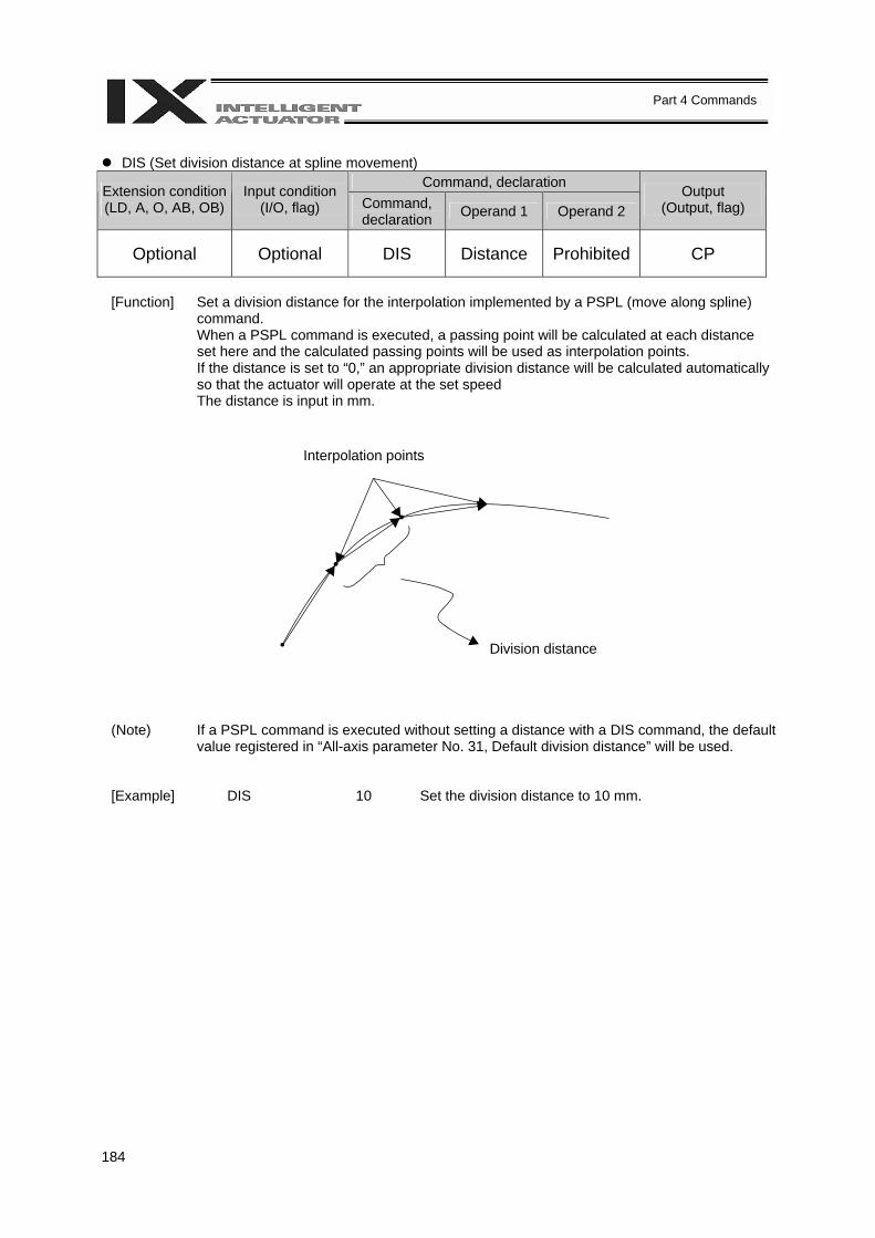
184
Part 4 Commands
DIS (Set division distance at spline movement)
Command, declaration Extension condition (LD, A, O, AB, OB)
Input condition (I/O, flag) Command,
declaration Operand 1 Operand 2 Output
(Output, flag)
Optional Optional DIS Distance Prohibited CP
[Function] Set a division distance for the interpolation implemented by a PSPL (move along spline)
command. When a PSPL command is executed, a passing point will be calculated at each distance set here and the calculated passing points will be used as interpolation points. If the distance is set to “0,” an appropriate division distance will be calculated automatically so that the actuator will operate at the set speed The distance is input in mm.
(Note) If a PSPL command is executed without setting a distance with a DIS command, the default value registered in “All-axis parameter No. 31, Default division distance” will be used.
[Example] DIS 10 Set the division distance to 10 mm.
Interpolation points
Division distance
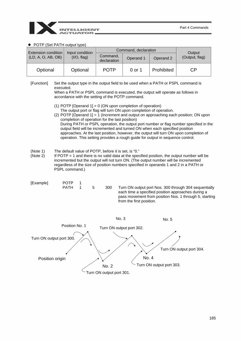
185
Part 4 Commands
POTP (Set PATH output type)
Command, declaration Extension condition (LD, A, O, AB, OB)
Input condition (I/O, flag) Command,
declaration Operand 1 Operand 2 Output
(Output, flag)
Optional Optional POTP 0 or 1 Prohibited CP
[Function] Set the output type in the output field to be used when a PATH or PSPL command is
executed. When a PATH or PSPL command is executed, the output will operate as follows in accordance with the setting of the POTP command.
(1) POTP [Operand 1] = 0 (ON upon completion of operation)
The output port or flag will turn ON upon completion of operation. (2) POTP [Operand 1] = 1 (Increment and output on approaching each position; ON upon
completion of operation for the last position) During PATH or PSPL operation, the output port number or flag number specified in the output field will be incremented and turned ON when each specified position approaches. At the last position, however, the output will turn ON upon completion of operation. This setting provides a rough guide for output in sequence control.
(Note 1) The default value of POTP, before it is set, is “0.” (Note 2) If POTP = 1 and there is no valid data at the specified position, the output number will be
incremented but the output will not turn ON. (The output number will be incremented regardless of the size of position numbers specified in operands 1 and 2 in a PATH or PSPL command.)
[Example] POTP 1 PATH 1 5 300 Turn ON output port Nos. 300 through 304 sequentially
each time a specified position approaches during a pass movement from position Nos. 1 through 5, starting from the first position.
Position No. 1
No. 3 No. 5
Turn ON output port 300.
Position origin
No. 2
No. 4
Turn ON output port 301.
Turn ON output port 303.
Turn ON output port 304.
Turn ON output port 302.

186
Part 4 Commands
PAPR (Set push-motion approach distance, speed)
Command, declaration Extension condition (LD, A, O, AB, OB)
Input condition (I/O, flag) Command,
declaration Operand 1 Operand 2 Output
(Output, flag)
Optional Optional PAPR Distance Speed CP
[Function] Set the operation to be performed when a PUSH command is executed.
Set the distance (push-motion approach distance) over which push-motion approach operation (torque-limiting operation) will be performed in operand 1 (in mm), and set the speed (push-motion approach speed) at which push-motion approach operation (torque-limiting operation) will be performed in operand 2 (in mm/sec). The push-motion approach distance specified in operand 1 may contain up to three decimal places, while the speed specified in operand 2 cannot contain any decimal place.
[Example] PAPR 100 30 MOVP 10 PUSH 11
Set the push-motion approach distance in a PUSH command to 100 mm and the push-motion approach speed to 30 mm/sec.
(Note) When an OVRD command is used, the push-motion approach speed is clamped by the minimum speed of 1 mm/sec. (The minimum speed does not guarantee reliable push motion operation. If low-speed push-motion approach is needed, confirm the operation on the actual machine by considering the effects of mechanical characteristics, etc.)
Position origin
Push-motion approach distance
Start position of push-motion approach operation (torque-limiting operation)
Z
Y
X
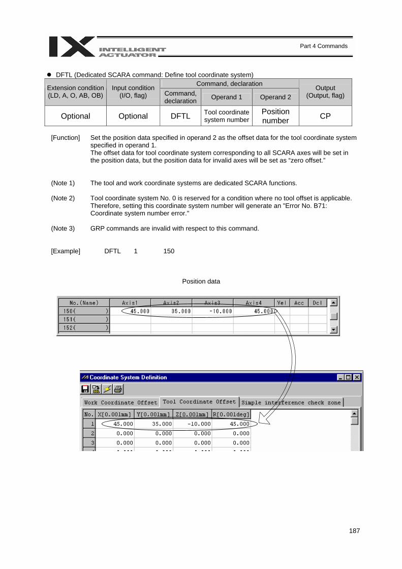
187
Part 4 Commands
DFTL (Dedicated SCARA command: Define tool coordinate system)
Command, declaration Extension condition (LD, A, O, AB, OB)
Input condition (I/O, flag) Command,
declaration Operand 1 Operand 2 Output
(Output, flag)
Optional Optional DFTL Tool coordinate system number
Position number CP
[Function] Set the position data specified in operand 2 as the offset data for the tool coordinate system
specified in operand 1. The offset data for tool coordinate system corresponding to all SCARA axes will be set in the position data, but the position data for invalid axes will be set as “zero offset.”
(Note 1)
The tool and work coordinate systems are dedicated SCARA functions.
(Note 2) Tool coordinate system No. 0 is reserved for a condition where no tool offset is applicable. Therefore, setting this coordinate system number will generate an "Error No. B71: Coordinate system number error."
(Note 3) GRP commands are invalid with respect to this command.
[Example] DFTL 1 150
Position data
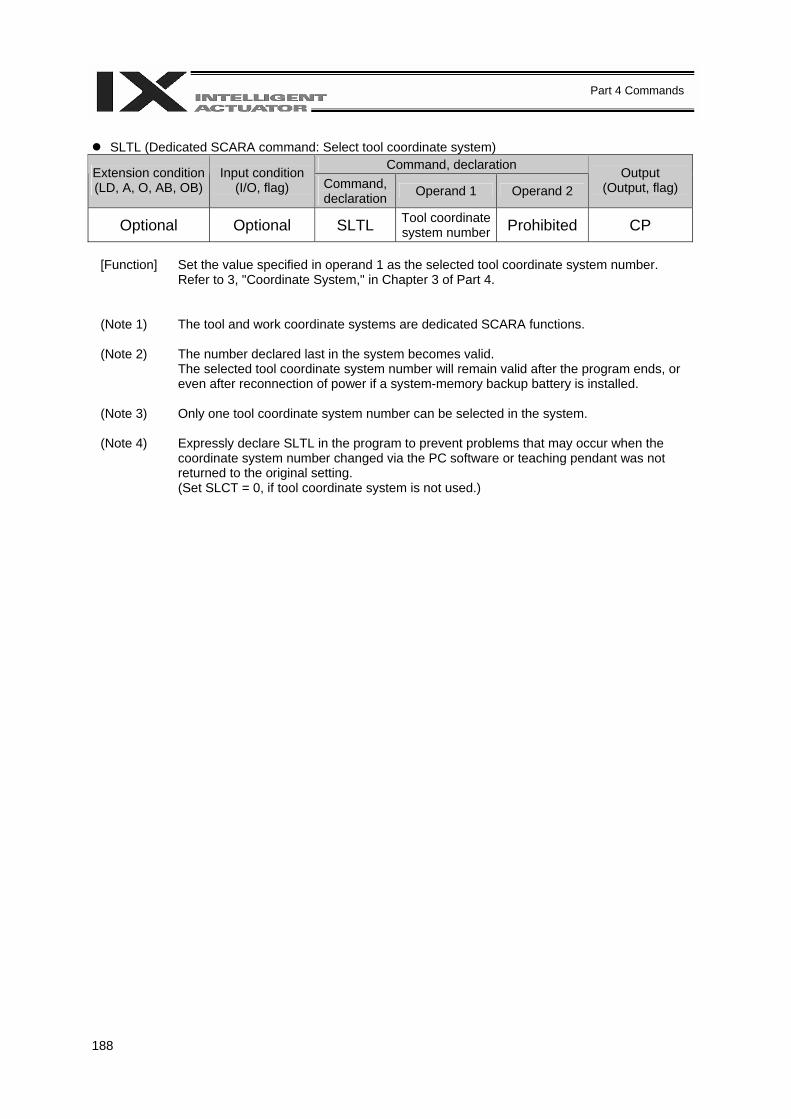
188
Part 4 Commands
SLTL (Dedicated SCARA command: Select tool coordinate system)
Command, declaration Extension condition (LD, A, O, AB, OB)
Input condition (I/O, flag) Command,
declaration Operand 1 Operand 2 Output
(Output, flag)
Optional Optional SLTL Tool coordinate system number Prohibited CP
[Function] Set the value specified in operand 1 as the selected tool coordinate system number.
Refer to 3, "Coordinate System," in Chapter 3 of Part 4.
(Note 1) The tool and work coordinate systems are dedicated SCARA functions. (Note 2) The number declared last in the system becomes valid.
The selected tool coordinate system number will remain valid after the program ends, or even after reconnection of power if a system-memory backup battery is installed.
(Note 3) Only one tool coordinate system number can be selected in the system. (Note 4) Expressly declare SLTL in the program to prevent problems that may occur when the
coordinate system number changed via the PC software or teaching pendant was not returned to the original setting. (Set SLCT = 0, if tool coordinate system is not used.)
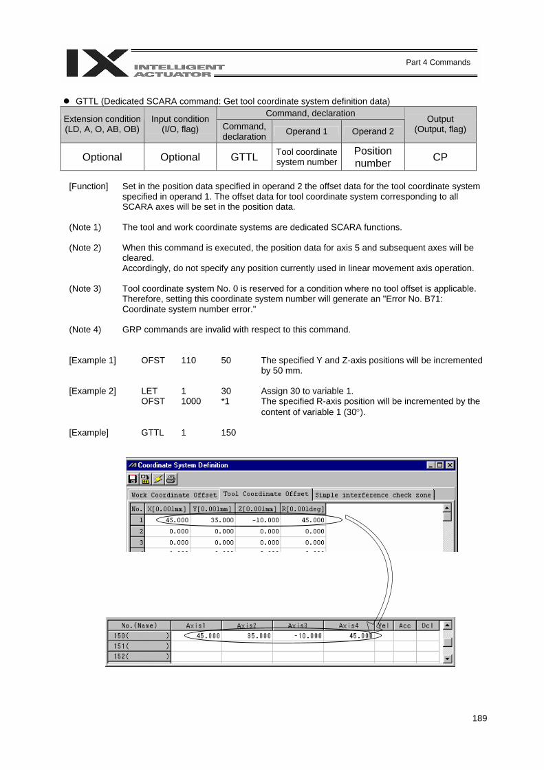
189
Part 4 Commands
GTTL (Dedicated SCARA command: Get tool coordinate system definition data)
Command, declaration Extension condition (LD, A, O, AB, OB)
Input condition (I/O, flag) Command,
declaration Operand 1 Operand 2 Output
(Output, flag)
Optional Optional GTTL Tool coordinate system number
Position number CP
[Function] Set in the position data specified in operand 2 the offset data for the tool coordinate system
specified in operand 1. The offset data for tool coordinate system corresponding to all SCARA axes will be set in the position data.
(Note 1) The tool and work coordinate systems are dedicated SCARA functions.
(Note 2) When this command is executed, the position data for axis 5 and subsequent axes will be
cleared. Accordingly, do not specify any position currently used in linear movement axis operation.
(Note 3) Tool coordinate system No. 0 is reserved for a condition where no tool offset is applicable. Therefore, setting this coordinate system number will generate an "Error No. B71: Coordinate system number error."
(Note 4) GRP commands are invalid with respect to this command.
[Example 1] OFST 110 50 The specified Y and Z-axis positions will be incremented by 50 mm.
[Example 2] LET
OFST 1 1000
30 *1
Assign 30 to variable 1. The specified R-axis position will be incremented by the content of variable 1 (30°).
[Example] GTTL 1 150
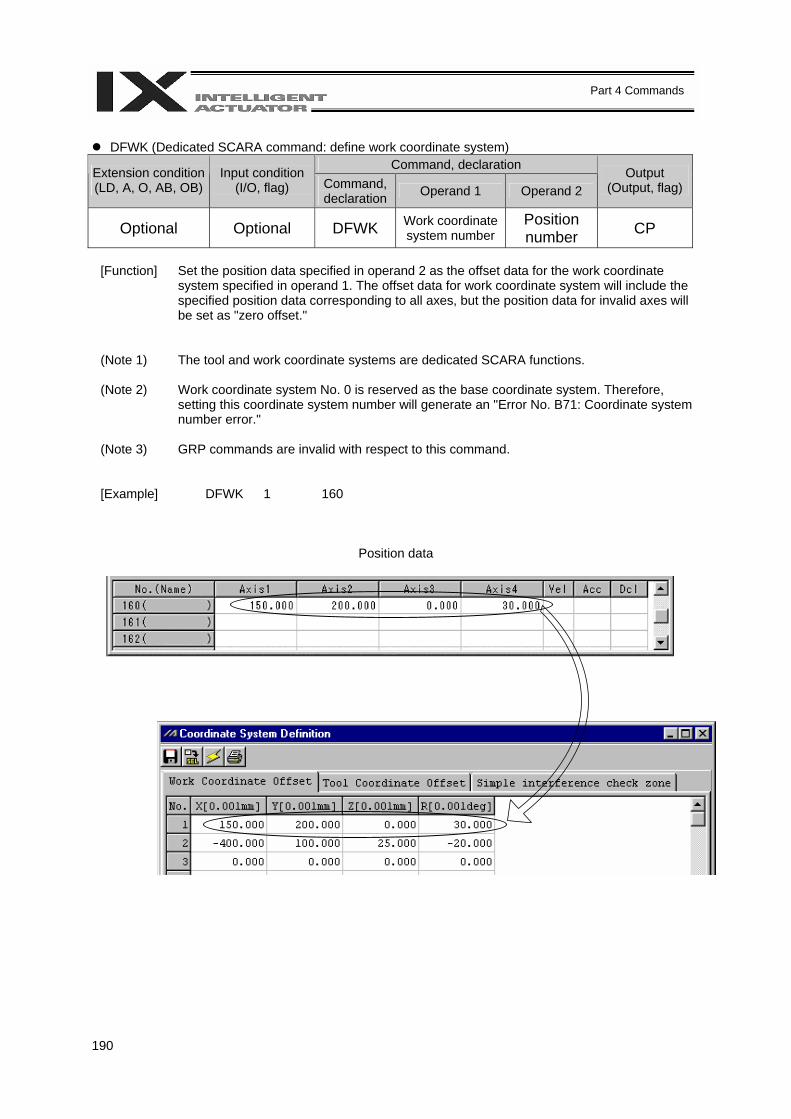
190
Part 4 Commands
DFWK (Dedicated SCARA command: define work coordinate system)
Command, declaration Extension condition (LD, A, O, AB, OB)
Input condition (I/O, flag) Command,
declaration Operand 1 Operand 2 Output
(Output, flag)
Optional Optional DFWK Work coordinate system number
Position number CP
[Function] Set the position data specified in operand 2 as the offset data for the work coordinate
system specified in operand 1. The offset data for work coordinate system will include the specified position data corresponding to all axes, but the position data for invalid axes will be set as "zero offset."
(Note 1) The tool and work coordinate systems are dedicated SCARA functions.
(Note 2) Work coordinate system No. 0 is reserved as the base coordinate system. Therefore, setting this coordinate system number will generate an "Error No. B71: Coordinate system number error."
(Note 3) GRP commands are invalid with respect to this command.
[Example] DFWK 1 160
Position data

191
Part 4 Commands
SLWK (Dedicated SCARA command: select work coordinate system)
Command, declaration Extension condition (LD, A, O, AB, OB)
Input condition (I/O, flag) Command,
declaration Operand 1 Operand 2 Output
(Output, flag)
Optional Optional SLWK Work coordinate system number Prohibited CP
[Function] Set the value specified in operand 1 as the selected work coordinate system number.
Refer to 3, "Coordinate System," in Chapter 3 of Part 4.
(Note 1) The tool and work coordinate systems are dedicated SCARA functions.
(Note 2) The number declared last in the system becomes valid. The selected work coordinate system number will remain valid after the program ends, or even after reconnection of power if a system-memory backup battery is installed.
(Note 3) Only one work coordinate system number can be selected in the system.
(Note 4) Expressly declare SLWK in the program to prevent problems that may occur when the coordinate system number changed via the PC software or teaching pendant was not returned to the original setting. (Set SLWK = 0, if work coordinate system is not used.)
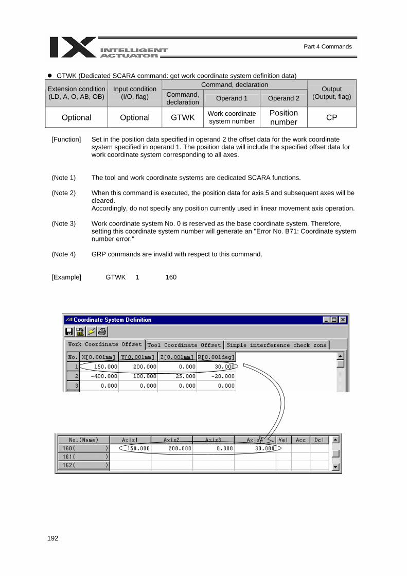
192
Part 4 Commands
GTWK (Dedicated SCARA command: get work coordinate system definition data)
Command, declaration Extension condition (LD, A, O, AB, OB)
Input condition (I/O, flag) Command,
declaration Operand 1 Operand 2 Output
(Output, flag)
Optional Optional GTWK Work coordinate system number
Position number CP
[Function] Set in the position data specified in operand 2 the offset data for the work coordinate
system specified in operand 1. The position data will include the specified offset data for work coordinate system corresponding to all axes.
(Note 1) The tool and work coordinate systems are dedicated SCARA functions.
(Note 2) When this command is executed, the position data for axis 5 and subsequent axes will be cleared. Accordingly, do not specify any position currently used in linear movement axis operation.
(Note 3) Work coordinate system No. 0 is reserved as the base coordinate system. Therefore, setting this coordinate system number will generate an "Error No. B71: Coordinate system number error."
(Note 4) GRP commands are invalid with respect to this command.
[Example] GTWK 1 160
193
Part 4 Commands
RIGH (Dedicated SCARA command: change current arm system to right arm (Arm 2 may operate if the
current arm system is the opposite arm)) Command, declaration Extension condition
(LD, A, O, AB, OB) Input condition
(I/O, flag) Command, declaration Operand 1 Operand 2
Output (Output, flag)
Optional Optional RIGH Prohibited Prohibited PE
[Function] Change the current SCARA arm system to the right arm system. If the current arm system is the left arm system, arm 2 will be operated to change the arm system to the right arm system. After this operation, arms 1 and 2 will form a straight line. If the current arm system is the right arm system, no arm operation will take place. (For details, refer to 2, "Arm System," in Chapter 3 of Part 4.)
(Note 1) When a RIGH or LEFT command is used, the speed must be set via VELS even when
SCARA PTP operation commands are not used.
194
Part 4 Commands
LEFT (Dedicated SCARA command: change current arm system to left arm (Arm 2 may operate if the
current arm system is the opposite arm)) Command, declaration Extension condition
(LD, A, O, AB, OB) Input condition
(I/O, flag) Command, declaration Operand 1 Operand 2
Output (Output, flag)
Optional Optional LEFT Prohibited Prohibited PE
[Function] Change the current SCARA arm system to the left arm system. If the current arm system is the right arm system, arm 2 will be operated to change the arm system to the left arm system. After this operation, arms 1 and 2 will form a straight line. If the current arm system is the left arm system, no arm operation will take place. (For details, refer to 2, "Arm System," in Chapter 3 of Part 4.)
(Note 1) When a RIGH or LEFT command is used, the speed must be set via VELS even when
SCARA PTP operation commands are not used.

195
Part 4 Commands
PTPR (Dedicated SCARA command: specify right arm as PTP target arm system (Movement of the
opposite arm system is prohibited when the target value cannot be achieved) (No arm operation)) Command, declaration Extension condition
(LD, A, O, AB, OB) Input condition
(I/O, flag) Command, declaration Operand 1 Operand 2
Output (Output, flag)
Optional Optional PTPR Prohibited Prohibited CP
[Function] Specify the right arm system as the target arm system for SCARA PTP operation command. Once a PTPR command is executed, the target arm system for SCARA PTP operation command will become the right arm system and any target value that cannot be achieved with the right arm system will generate an error. Executing this command itself will not accompany any arm operation. (For details, refer to 2, "Arm System," in Chapter 3 of Part 4.)
196
Part 4 Commands
PTPL (Dedicated SCARA command: specify left arm as PTP target arm system (Movement of the
opposite arm system is prohibited when the target value cannot be achieved) (No arm operation)) Command, declaration Extension condition
(LD, A, O, AB, OB) Input condition
(I/O, flag) Command, declaration Operand 1 Operand 2
Output (Output, flag)
Optional Optional PTPL Prohibited Prohibited CP
[Function] Specify the left arm system as the target arm system for SCARA PTP operation command. Once a PTPL command is executed, the target arm system for SCARA PTP operation command will become the left arm system and any target value that cannot be achieved with the left arm system will generate an error. Executing this command itself will not accompany any arm operation. (For details, refer to 2, "Arm System," in Chapter 3 of Part 4.)
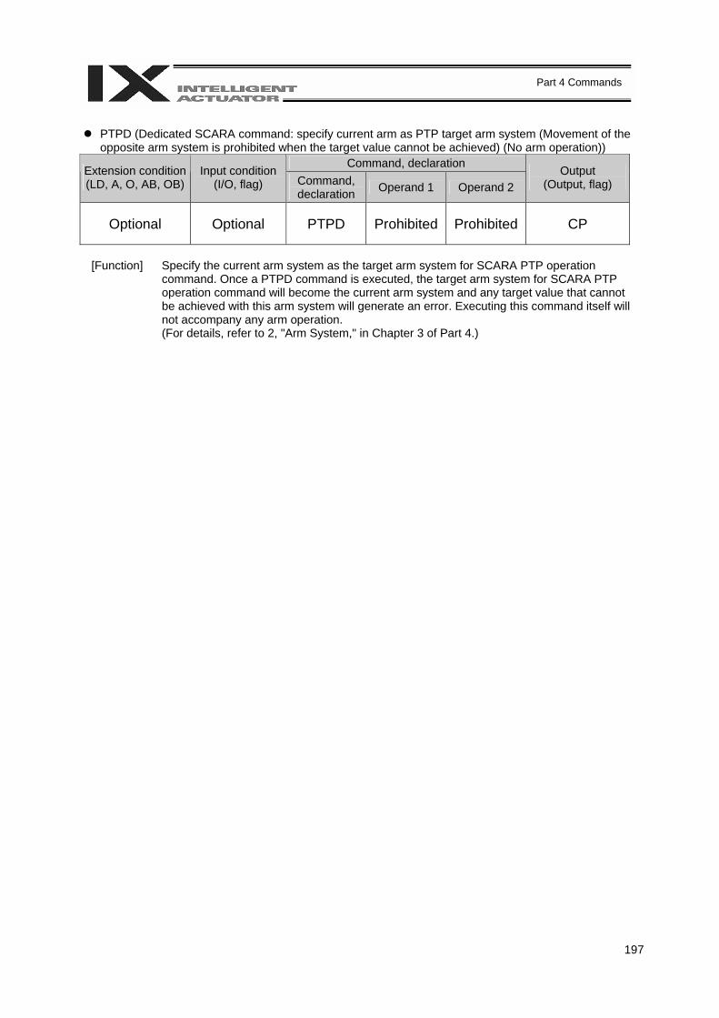
197
Part 4 Commands
PTPD (Dedicated SCARA command: specify current arm as PTP target arm system (Movement of the
opposite arm system is prohibited when the target value cannot be achieved) (No arm operation)) Command, declaration Extension condition
(LD, A, O, AB, OB) Input condition
(I/O, flag) Command, declaration Operand 1 Operand 2
Output (Output, flag)
Optional Optional PTPD Prohibited Prohibited CP
[Function] Specify the current arm system as the target arm system for SCARA PTP operation
command. Once a PTPD command is executed, the target arm system for SCARA PTP operation command will become the current arm system and any target value that cannot be achieved with this arm system will generate an error. Executing this command itself will not accompany any arm operation. (For details, refer to 2, "Arm System," in Chapter 3 of Part 4.)
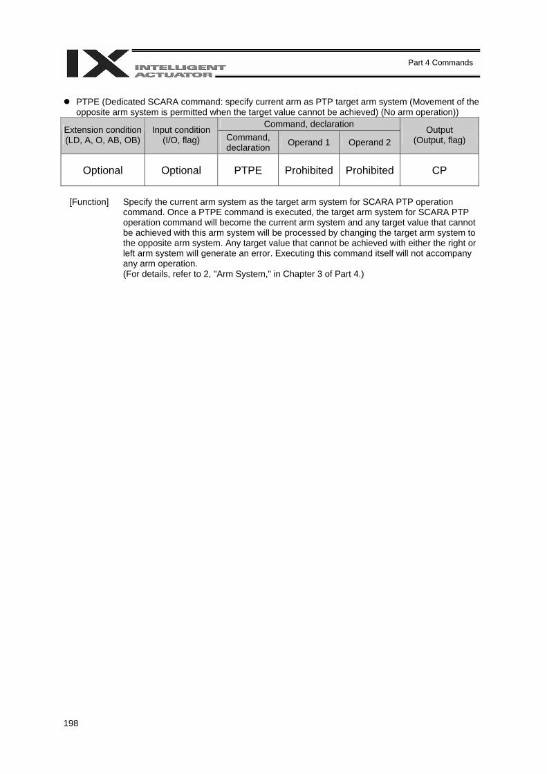
198
Part 4 Commands
PTPE (Dedicated SCARA command: specify current arm as PTP target arm system (Movement of the
opposite arm system is permitted when the target value cannot be achieved) (No arm operation)) Command, declaration Extension condition
(LD, A, O, AB, OB) Input condition
(I/O, flag) Command, declaration Operand 1 Operand 2
Output (Output, flag)
Optional Optional PTPE Prohibited Prohibited CP
[Function] Specify the current arm system as the target arm system for SCARA PTP operation
command. Once a PTPE command is executed, the target arm system for SCARA PTP operation command will become the current arm system and any target value that cannot be achieved with this arm system will be processed by changing the target arm system to the opposite arm system. Any target value that cannot be achieved with either the right or left arm system will generate an error. Executing this command itself will not accompany any arm operation. (For details, refer to 2, "Arm System," in Chapter 3 of Part 4.)

199
Part 4 Commands
DFIF (Dedicated SCARA command: define coordinates of simple interference check zone)
Command, declaration Extension condition (LD, A, O, AB, OB)
Input condition (I/O, flag) Command,
declaration Operand 1 Operand 2 Output
(Output, flag)
Optional Optional DFIF Interference check zone
number
Position number (Consecutive two
positions will be used) CP
[Function] Set the consecutive two position data starting from the position number specified in
operand 2 as the coordinate data defining the simple interference check zone specified in operand 1. The position data specified in operand 2 will be set as definition coordinates 1 of the simple interference check zone, while the next position data will be set as definition coordinates 2. If the axis patterns of the consecutive two position data do not match, an "Error No. C30: Axis pattern error" will generate.
(Note 1) The simple interference check zone is a dedicated SCARA function. (Note 2) The definition coordinates of simple interference check zone are always treated as data on
the base coordinate system (work coordinate system No. 0). Therefore, to provide position data for valid definition coordinates for the purpose of executing a DFIF command, the data must be set on the base coordinate system beforehand.
(Note 3) After the definition coordinates of simple interference check zone are changed, it will take 5 msec before the check result reflects the new settings.
(Note 4) GRP commands are invalid with respect to this command.
[Example 1] DFIF 1 170
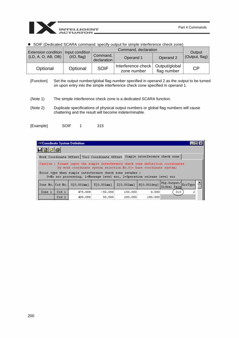
200
Part 4 Commands
SOIF (Dedicated SCARA command: specify output for simple interference check zone)
Command, declaration Extension condition (LD, A, O, AB, OB)
Input condition (I/O, flag) Command,
declaration Operand 1 Operand 2 Output
(Output, flag)
Optional Optional SOIF Interference check zone number
Output/global flag number CP
[Function] Set the output number/global flag number specified in operand 2 as the output to be turned
on upon entry into the simple interference check zone specified in operand 1.
(Note 1) The simple interference check zone is a dedicated SCARA function.
(Note 2) Duplicate specifications of physical output numbers or global flag numbers will cause chattering and the result will become indeterminable.
[Example] SOIF 1 315
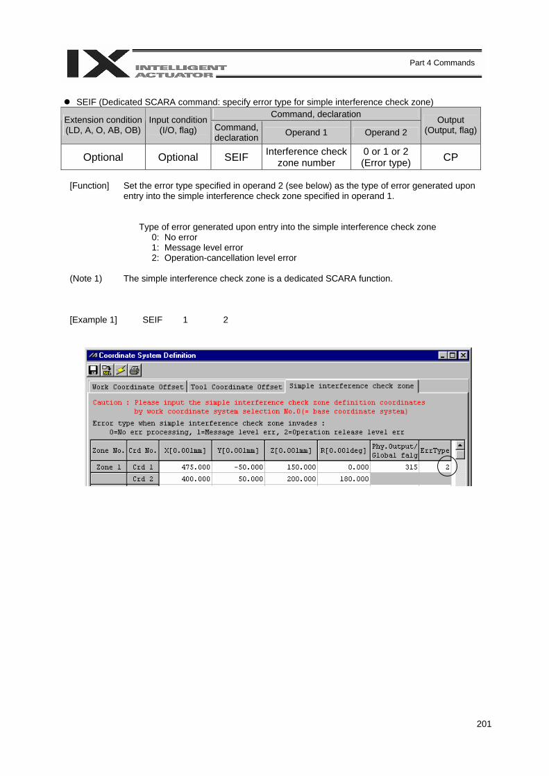
201
Part 4 Commands
SEIF (Dedicated SCARA command: specify error type for simple interference check zone)
Command, declaration Extension condition (LD, A, O, AB, OB)
Input condition (I/O, flag) Command,
declaration Operand 1 Operand 2 Output
(Output, flag)
Optional Optional SEIF Interference check zone number
0 or 1 or 2 (Error type) CP
[Function] Set the error type specified in operand 2 (see below) as the type of error generated upon
entry into the simple interference check zone specified in operand 1.
Type of error generated upon entry into the simple interference check zone 0: No error 1: Message level error 2: Operation-cancellation level error
(Note 1) The simple interference check zone is a dedicated SCARA function.
[Example 1] SEIF 1 2
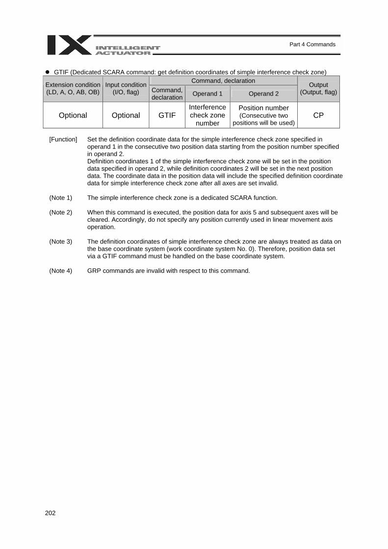
202
Part 4 Commands
GTIF (Dedicated SCARA command: get definition coordinates of simple interference check zone)
Command, declaration Extension condition (LD, A, O, AB, OB)
Input condition (I/O, flag) Command,
declaration Operand 1 Operand 2 Output
(Output, flag)
Optional Optional GTIF Interference check zone
number
Position number (Consecutive two
positions will be used) CP
[Function] Set the definition coordinate data for the simple interference check zone specified in
operand 1 in the consecutive two position data starting from the position number specified in operand 2. Definition coordinates 1 of the simple interference check zone will be set in the position data specified in operand 2, while definition coordinates 2 will be set in the next position data. The coordinate data in the position data will include the specified definition coordinate data for simple interference check zone after all axes are set invalid.
(Note 1) The simple interference check zone is a dedicated SCARA function.
(Note 2) When this command is executed, the position data for axis 5 and subsequent axes will be
cleared. Accordingly, do not specify any position currently used in linear movement axis operation.
(Note 3) The definition coordinates of simple interference check zone are always treated as data on the base coordinate system (work coordinate system No. 0). Therefore, position data set via a GTIF command must be handled on the base coordinate system.
(Note 4) GRP commands are invalid with respect to this command.
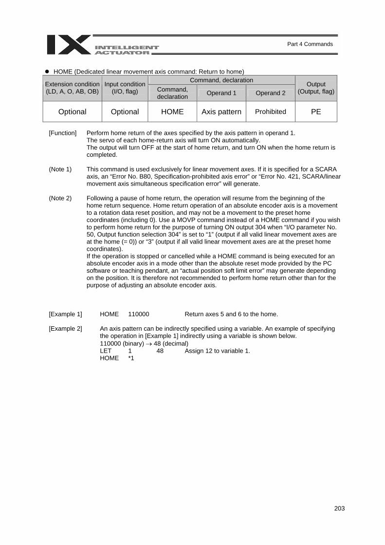
203
Part 4 Commands
HOME (Dedicated linear movement axis command: Return to home)
Command, declaration Extension condition (LD, A, O, AB, OB)
Input condition (I/O, flag) Command,
declaration Operand 1 Operand 2 Output
(Output, flag)
Optional Optional HOME Axis pattern Prohibited PE
[Function] Perform home return of the axes specified by the axis pattern in operand 1.
The servo of each home-return axis will turn ON automatically. The output will turn OFF at the start of home return, and turn ON when the home return is completed.
(Note 1) This command is used exclusively for linear movement axes. If it is specified for a SCARA
axis, an “Error No. B80, Specification-prohibited axis error” or “Error No. 421, SCARA/linear movement axis simultaneous specification error” will generate.
(Note 2) Following a pause of home return, the operation will resume from the beginning of the home return sequence. Home return operation of an absolute encoder axis is a movement to a rotation data reset position, and may not be a movement to the preset home coordinates (including 0). Use a MOVP command instead of a HOME command if you wish to perform home return for the purpose of turning ON output 304 when “I/O parameter No. 50, Output function selection 304” is set to “1” (output if all valid linear movement axes are at the home (= 0)) or “3” (output if all valid linear movement axes are at the preset home coordinates). If the operation is stopped or cancelled while a HOME command is being executed for an absolute encoder axis in a mode other than the absolute reset mode provided by the PC software or teaching pendant, an “actual position soft limit error” may generate depending on the position. It is therefore not recommended to perform home return other than for the purpose of adjusting an absolute encoder axis.
[Example 1] HOME 110000 Return axes 5 and 6 to the home. [Example 2] An axis pattern can be indirectly specified using a variable. An example of specifying
the operation in [Example 1] indirectly using a variable is shown below. 110000 (binary) → 48 (decimal)
LET 1 48 Assign 12 to variable 1. HOME *1
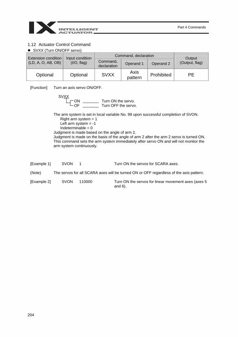
204
Part 4 Commands
1.12 Actuator Control Command
SVXX (Turn ON/OFF servo) Command, declaration Extension condition
(LD, A, O, AB, OB) Input condition
(I/O, flag) Command, declaration Operand 1 Operand 2
Output (Output, flag)
Optional Optional SVXX Axis pattern Prohibited PE
[Function] Turn an axis servo ON/OFF.
SVXX ON Turn ON the servo. OF Turn OFF the servo.
The arm system is set in local variable No. 99 upon successful completion of SVON.
Right arm system = 1 Left arm system = -1 Indeterminable = 0
Judgment is made based on the angle of arm 2. Judgment is made on the basis of the angle of arm 2 after the arm 2 servo is turned ON. This command sets the arm system immediately after servo ON and will not monitor the arm system continuously.
[Example 1] SVON 1 Turn ON the servos for SCARA axes. (Note) The servos for all SCARA axes will be turned ON or OFF regardless of the axis pattern. [Example 2] SVON 110000 Turn ON the servos for linear movement axes (axes 5
and 6).
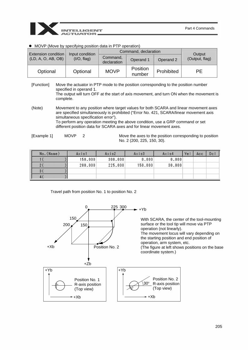
205
Part 4 Commands
MOVP (Move by specifying position data in PTP operation)
Command, declaration Extension condition (LD, A, O, AB, OB)
Input condition (I/O, flag) Command,
declaration Operand 1 Operand 2 Output
(Output, flag)
Optional Optional MOVP Position number Prohibited PE
[Function] Move the actuator in PTP mode to the position corresponding to the position number
specified in operand 1. The output will turn OFF at the start of axis movement, and turn ON when the movement is complete.
(Note) Movement to any position where target values for both SCARA and linear movement axes
are specified simultaneously is prohibited (“Error No. 421, SCARA/linear movement axis simultaneous specification error”). To perform any operation meeting the above condition, use a GRP command or set different position data for SCARA axes and for linear movement axes.
[Example 1] MOVP 2 Move the axes to the position corresponding to position
No. 2 (200, 225, 150, 30).
Travel path from position No. 1 to position No. 2
With SCARA, the center of the tool-mounting surface or the tool tip will move via PTP operation (not linearly). The movement locus will vary depending on the starting position and end position of operation, arm system, etc. (The figure at left shows positions on the base coordinate system.)
Position No. 1 R-axis position (Top view)
Position No. 2 R-axis position (Top view)
0 225 300 +Yb
+Xb
+Zb
Position No. 2
150 200 150
+Yb +Yb
+Xb +Xb
30°
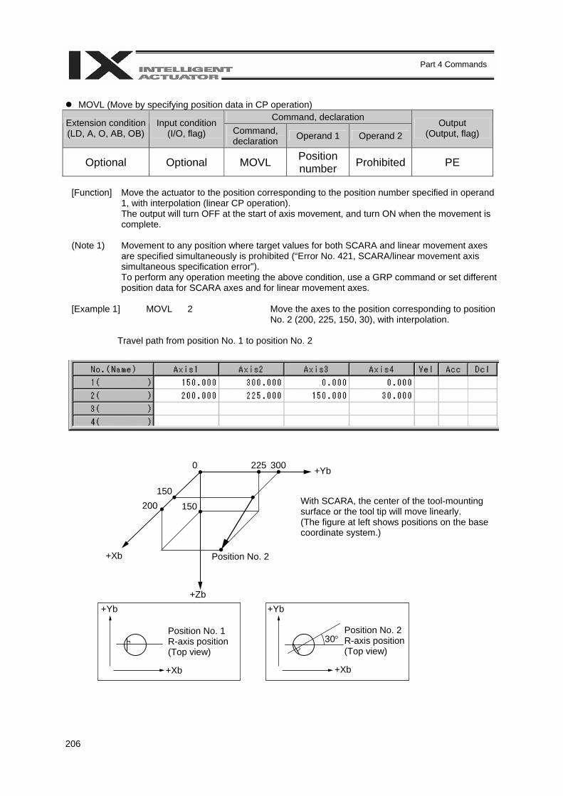
206
Part 4 Commands
MOVL (Move by specifying position data in CP operation)
Command, declaration Extension condition (LD, A, O, AB, OB)
Input condition (I/O, flag) Command,
declaration Operand 1 Operand 2 Output
(Output, flag)
Optional Optional MOVL Position number Prohibited PE
[Function] Move the actuator to the position corresponding to the position number specified in operand
1, with interpolation (linear CP operation). The output will turn OFF at the start of axis movement, and turn ON when the movement is complete.
(Note 1) Movement to any position where target values for both SCARA and linear movement axes are specified simultaneously is prohibited (“Error No. 421, SCARA/linear movement axis simultaneous specification error”). To perform any operation meeting the above condition, use a GRP command or set different position data for SCARA axes and for linear movement axes.
[Example 1] MOVL 2 Move the axes to the position corresponding to position No. 2 (200, 225, 150, 30), with interpolation.
Travel path from position No. 1 to position No. 2
With SCARA, the center of the tool-mounting surface or the tool tip will move linearly. (The figure at left shows positions on the base coordinate system.)
Position No. 1 R-axis position (Top view)
Position No. 2 R-axis position (Top view)
0 225 300 +Yb
+Xb
+Zb
Position No. 2
150 200 150
+Yb +Yb
+Xb +Xb
30°
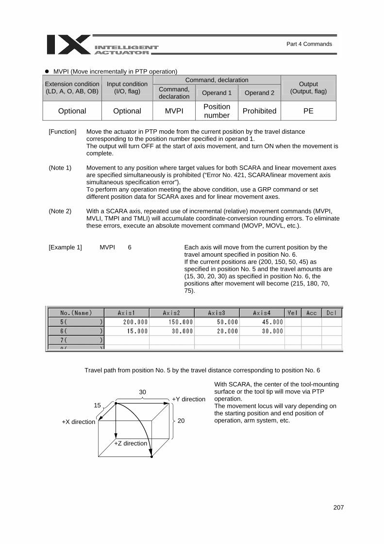
207
Part 4 Commands
MVPI (Move incrementally in PTP operation)
Command, declaration Extension condition (LD, A, O, AB, OB)
Input condition (I/O, flag) Command,
declaration Operand 1 Operand 2 Output
(Output, flag)
Optional Optional MVPI Position number Prohibited PE
[Function] Move the actuator in PTP mode from the current position by the travel distance
corresponding to the position number specified in operand 1. The output will turn OFF at the start of axis movement, and turn ON when the movement is complete.
(Note 1) Movement to any position where target values for both SCARA and linear movement axes
are specified simultaneously is prohibited (“Error No. 421, SCARA/linear movement axis simultaneous specification error”). To perform any operation meeting the above condition, use a GRP command or set different position data for SCARA axes and for linear movement axes.
(Note 2) With a SCARA axis, repeated use of incremental (relative) movement commands (MVPI, MVLI, TMPI and TMLI) will accumulate coordinate-conversion rounding errors. To eliminate these errors, execute an absolute movement command (MOVP, MOVL, etc.).
[Example 1] MVPI 6 Each axis will move from the current position by the travel amount specified in position No. 6. If the current positions are (200, 150, 50, 45) as specified in position No. 5 and the travel amounts are (15, 30, 20, 30) as specified in position No. 6, the positions after movement will become (215, 180, 70, 75).
Travel path from position No. 5 by the travel distance corresponding to position No. 6
+X direction
With SCARA, the center of the tool-mounting surface or the tool tip will move via PTP operation. The movement locus will vary depending on the starting position and end position of operation, arm system, etc.
+Y direction
+Z direction
15
30
20
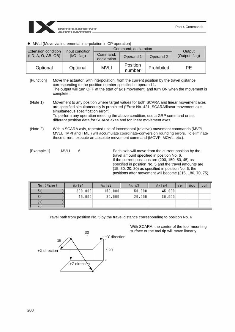
208
Part 4 Commands
MVLI (Move via incremental interpolation in CP operation)
Command, declaration Extension condition (LD, A, O, AB, OB)
Input condition (I/O, flag) Command,
declaration Operand 1 Operand 2 Output
(Output, flag)
Optional Optional MVLI Position number Prohibited PE
[Function] Move the actuator, with interpolation, from the current position by the travel distance
corresponding to the position number specified in operand 1. The output will turn OFF at the start of axis movement, and turn ON when the movement is complete.
(Note 1) Movement to any position where target values for both SCARA and linear movement axes are specified simultaneously is prohibited (“Error No. 421, SCARA/linear movement axis simultaneous specification error”). To perform any operation meeting the above condition, use a GRP command or set different position data for SCARA axes and for linear movement axes.
(Note 2) With a SCARA axis, repeated use of incremental (relative) movement commands (MVPI, MVLI, TMPI and TMLI) will accumulate coordinate-conversion rounding errors. To eliminate these errors, execute an absolute movement command (MOVP, MOVL, etc.).
[Example 1] MVLI 6 Each axis will move from the current position by the travel amount specified in position No. 6. If the current positions are (200, 150, 50, 45) as specified in position No. 5 and the travel amounts are (15, 30, 20, 30) as specified in position No. 6, the positions after movement will become (215, 180, 70, 75).
Travel path from position No. 5 by the travel distance corresponding to position No. 6
+X direction
With SCARA, the center of the tool-mounting surface or the tool tip will move linearly.
+Y direction
+Z direction
15
30
20
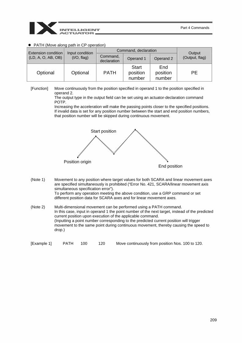
209
Part 4 Commands
PATH (Move along path in CP operation)
Command, declaration Extension condition (LD, A, O, AB, OB)
Input condition (I/O, flag) Command,
declaration Operand 1 Operand 2 Output
(Output, flag)
Optional Optional PATH Start
position number
End position number
PE
[Function] Move continuously from the position specified in operand 1 to the position specified in
operand 2. The output type in the output field can be set using an actuator-declaration command POTP. Increasing the acceleration will make the passing points closer to the specified positions. If invalid data is set for any position number between the start and end position numbers, that position number will be skipped during continuous movement.
(Note 1) Movement to any position where target values for both SCARA and linear movement axes are specified simultaneously is prohibited (“Error No. 421, SCARA/linear movement axis simultaneous specification error”). To perform any operation meeting the above condition, use a GRP command or set different position data for SCARA axes and for linear movement axes.
(Note 2) Multi-dimensional movement can be performed using a PATH command. In this case, input in operand 1 the point number of the next target, instead of the predicted current position upon execution of the applicable command. (Inputting a point number corresponding to the predicted current position will trigger movement to the same point during continuous movement, thereby causing the speed to drop.)
[Example 1] PATH 100 120 Move continuously from position Nos. 100 to 120.
Start position
Position origin End position
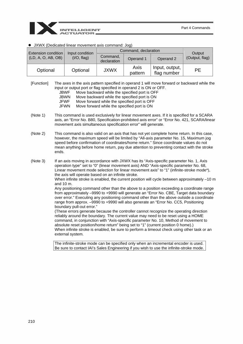
210
Part 4 Commands
JXWX (Dedicated linear movement axis command: Jog)
Command, declaration Extension condition (LD, A, O, AB, OB)
Input condition (I/O, flag) Command,
declaration Operand 1 Operand 2 Output
(Output, flag)
Optional Optional JXWX Axis pattern
Input, output, flag number PE
[Function] The axes in the axis pattern specified in operand 1 will move forward or backward while the
input or output port or flag specified in operand 2 is ON or OFF. JBWF Move backward while the specified port is OFF JBWN Move backward while the specified port is ON JFWF Move forward while the specified port is OFF JFWN Move forward while the specified port is ON
(Note 1) This command is used exclusively for linear movement axes. If it is specified for a SCARA
axis, an “Error No. B80, Specification-prohibited axis error” or “Error No. 421, SCARA/linear movement axis simultaneous specification error” will generate.
(Note 2) This command is also valid on an axis that has not yet complete home return. In this case, however, the maximum speed will be limited by “All-axis parameter No. 15, Maximum jog speed before confirmation of coordinates/home return.” Since coordinate values do not mean anything before home return, pay due attention to preventing contact with the stroke ends.
(Note 3) If an axis moving in accordance with JXWX has its “Axis-specific parameter No. 1, Axis operation type” set to “0” (linear movement axis) AND “Axis-specific parameter No. 68, Linear movement mode selection for linear movement axis” to “1” (infinite-stroke mode*), the axis will operate based on an infinite stroke. When infinite stroke is enabled, the current position will cycle between approximately –10 m and 10 m. Any positioning command other than the above to a position exceeding a coordinate range from approximately –9990 to +9990 will generate an “Error No. CBE, Target data boundary over error.” Executing any positioning command other than the above outside a coordinate range from approx. –9990 to +9990 will also generate an “Error No. CC5, Positioning boundary pull-out error.” (These errors generate because the controller cannot recognize the operating direction reliably around the boundary. The current value may need to be reset using a HOME command, in conjunction with “Axis-specific parameter No. 10, Method of movement to absolute reset position/home return” being set to “1” (current position 0 home).) When infinite stroke is enabled, be sure to perform a timeout check using other task or an external system.
The infinite-stroke mode can be specified only when an incremental encoder is used.
Be sure to contact IAI’s Sales Engineering if you wish to use the infinite-stroke mode.
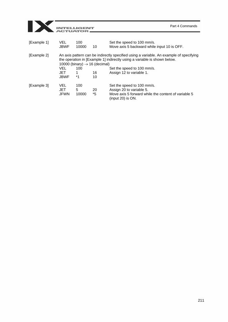
211
Part 4 Commands
[Example 1] VEL 100 Set the speed to 100 mm/s. JBWF 10000 10 Move axis 5 backward while input 10 is OFF. [Example 2] An axis pattern can be indirectly specified using a variable. An example of specifying
the operation in [Example 1] indirectly using a variable is shown below. 10000 (binary) → 16 (decimal)
VEL 100 Set the speed to 100 mm/s. JET 1 16 Assign 12 to variable 1. JBWF *1 10 [Example 3] VEL 100 Set the speed to 100 mm/s. JET 5 20 Assign 20 to variable 5. JFWN 10000 *5 Move axis 5 forward while the content of variable 5
(input 20) is ON.
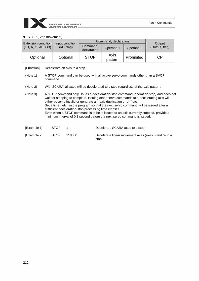
212
Part 4 Commands
STOP (Stop movement)
Command, declaration Extension condition (LD, A, O, AB, OB)
Input condition (I/O, flag) Command,
declaration Operand 1 Operand 2 Output
(Output, flag)
Optional Optional STOP Axis pattern Prohibited CP
[Function] Decelerate an axis to a stop. (Note 1) A STOP command can be used with all active servo commands other than a SVOF
command.
(Note 2) With SCARA, all axes will be decelerated to a stop regardless of the axis pattern.
(Note 3) A STOP command only issues a deceleration-stop command (operation stop) and does not wait for stopping to complete. Issuing other servo commands to a decelerating axis will either become invalid or generate an “axis duplication error,” etc. Set a timer, etc., in the program so that the next servo command will be issued after a sufficient deceleration-stop processing time elapses. Even when a STOP command is to be is issued to an axis currently stopped, provide a minimum interval of 0.1 second before the next servo command is issued.
[Example 1] STOP 1 Decelerate SCARA axes to a stop.
[Example 2] STOP 110000 Decelerate linear movement axes (axes 5 and 6) to a stop.
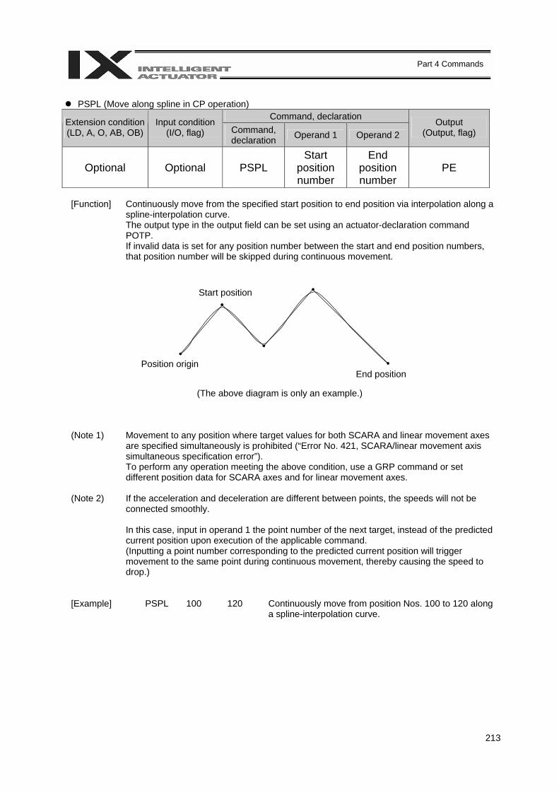
213
Part 4 Commands
PSPL (Move along spline in CP operation)
Command, declaration Extension condition (LD, A, O, AB, OB)
Input condition (I/O, flag) Command,
declaration Operand 1 Operand 2 Output
(Output, flag)
Optional Optional PSPL Start
position number
End position number
PE
[Function] Continuously move from the specified start position to end position via interpolation along a
spline-interpolation curve. The output type in the output field can be set using an actuator-declaration command POTP. If invalid data is set for any position number between the start and end position numbers, that position number will be skipped during continuous movement.
(The above diagram is only an example.)
(Note 1) Movement to any position where target values for both SCARA and linear movement axes are specified simultaneously is prohibited (“Error No. 421, SCARA/linear movement axis simultaneous specification error”). To perform any operation meeting the above condition, use a GRP command or set different position data for SCARA axes and for linear movement axes.
(Note 2) If the acceleration and deceleration are different between points, the speeds will not be connected smoothly. In this case, input in operand 1 the point number of the next target, instead of the predicted current position upon execution of the applicable command. (Inputting a point number corresponding to the predicted current position will trigger movement to the same point during continuous movement, thereby causing the speed to drop.)
[Example] PSPL 100 120 Continuously move from position Nos. 100 to 120 along a spline-interpolation curve.
Start position
Position origin End position
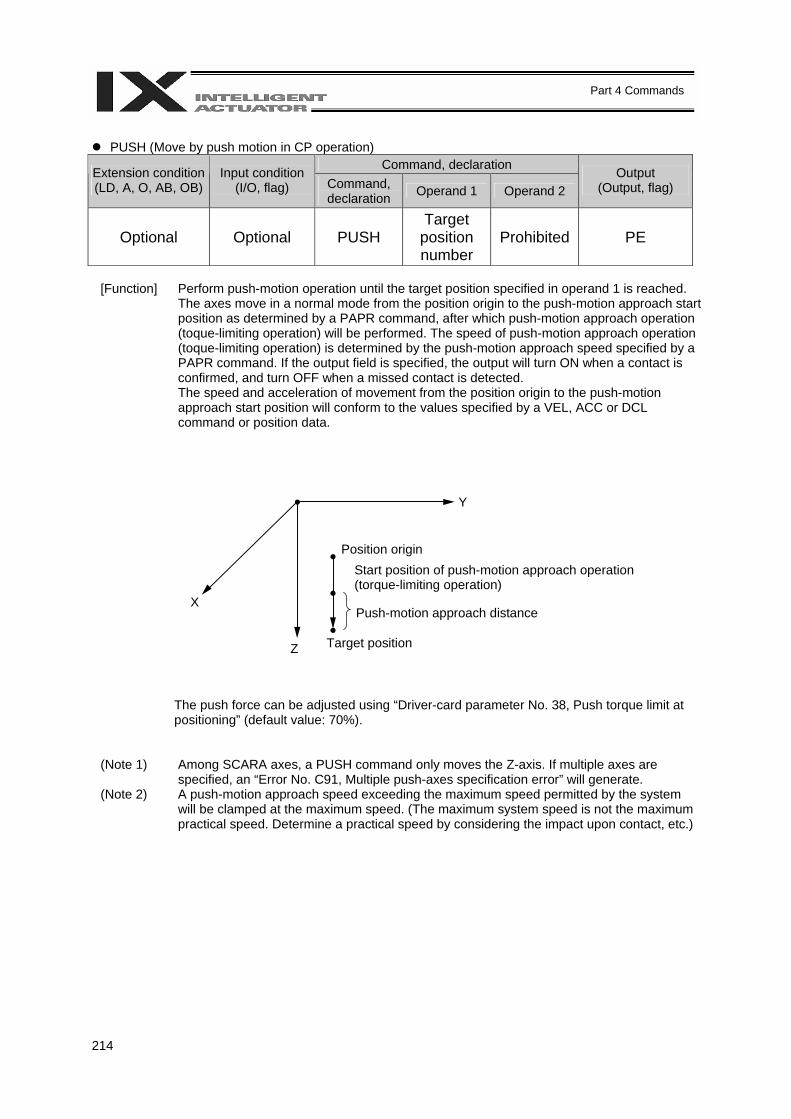
214
Part 4 Commands
PUSH (Move by push motion in CP operation)
Command, declaration Extension condition (LD, A, O, AB, OB)
Input condition (I/O, flag) Command,
declaration Operand 1 Operand 2 Output
(Output, flag)
Optional Optional PUSH Target
position number
Prohibited PE
[Function] Perform push-motion operation until the target position specified in operand 1 is reached.
The axes move in a normal mode from the position origin to the push-motion approach start position as determined by a PAPR command, after which push-motion approach operation (toque-limiting operation) will be performed. The speed of push-motion approach operation (toque-limiting operation) is determined by the push-motion approach speed specified by a PAPR command. If the output field is specified, the output will turn ON when a contact is confirmed, and turn OFF when a missed contact is detected. The speed and acceleration of movement from the position origin to the push-motion approach start position will conform to the values specified by a VEL, ACC or DCL command or position data.
The push force can be adjusted using “Driver-card parameter No. 38, Push torque limit at positioning” (default value: 70%).
(Note 1) Among SCARA axes, a PUSH command only moves the Z-axis. If multiple axes are specified, an “Error No. C91, Multiple push-axes specification error” will generate.
(Note 2) A push-motion approach speed exceeding the maximum speed permitted by the system will be clamped at the maximum speed. (The maximum system speed is not the maximum practical speed. Determine a practical speed by considering the impact upon contact, etc.)
Position origin
Push-motion approach distance
Target position
Start position of push-motion approach operation (torque-limiting operation)
Z
X
Y
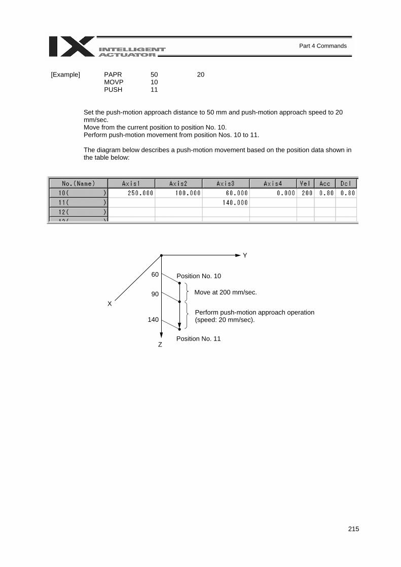
215
Part 4 Commands
[Example] PAPR 50 20 MOVP 10 PUSH 11
Set the push-motion approach distance to 50 mm and push-motion approach speed to 20 mm/sec. Move from the current position to position No. 10. Perform push-motion movement from position Nos. 10 to 11. The diagram below describes a push-motion movement based on the position data shown in the table below:
Move at 200 mm/sec.
Position No. 11
Perform push-motion approach operation (speed: 20 mm/sec).
Position No. 10
Y
X
Z
60
90
140
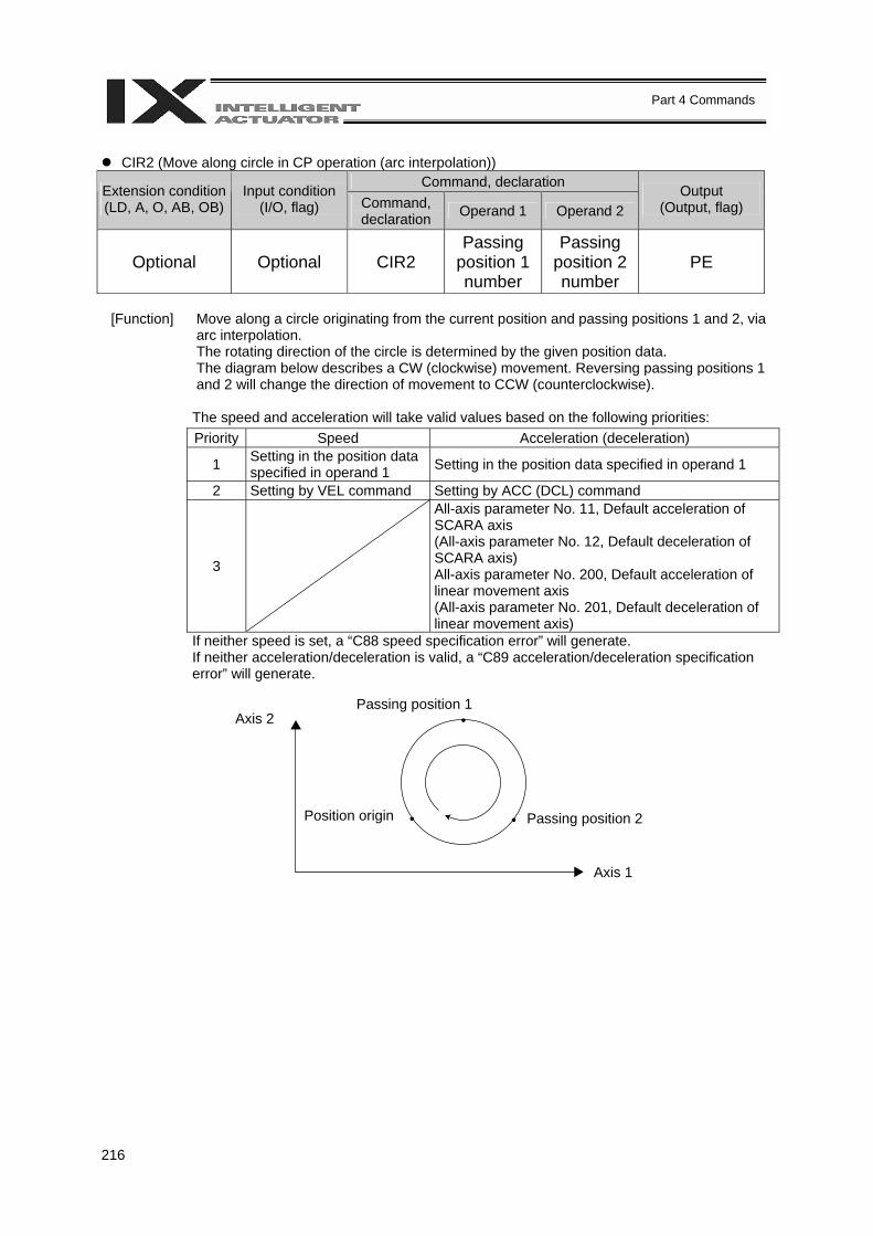
216
Part 4 Commands
CIR2 (Move along circle in CP operation (arc interpolation))
Command, declaration Extension condition (LD, A, O, AB, OB)
Input condition (I/O, flag) Command,
declaration Operand 1 Operand 2 Output
(Output, flag)
Optional Optional CIR2 Passing
position 1 number
Passing position 2 number
PE
[Function] Move along a circle originating from the current position and passing positions 1 and 2, via
arc interpolation. The rotating direction of the circle is determined by the given position data. The diagram below describes a CW (clockwise) movement. Reversing passing positions 1 and 2 will change the direction of movement to CCW (counterclockwise).
The speed and acceleration will take valid values based on the following priorities: Priority Speed Acceleration (deceleration)
1 Setting in the position data specified in operand 1 Setting in the position data specified in operand 1
2 Setting by VEL command Setting by ACC (DCL) command
3
All-axis parameter No. 11, Default acceleration of SCARA axis (All-axis parameter No. 12, Default deceleration of SCARA axis) All-axis parameter No. 200, Default acceleration of linear movement axis (All-axis parameter No. 201, Default deceleration of linear movement axis)
If neither speed is set, a “C88 speed specification error” will generate. If neither acceleration/deceleration is valid, a “C89 acceleration/deceleration specification error” will generate.
Passing position 1
Position origin
Axis 1
Axis 2
Passing position 2
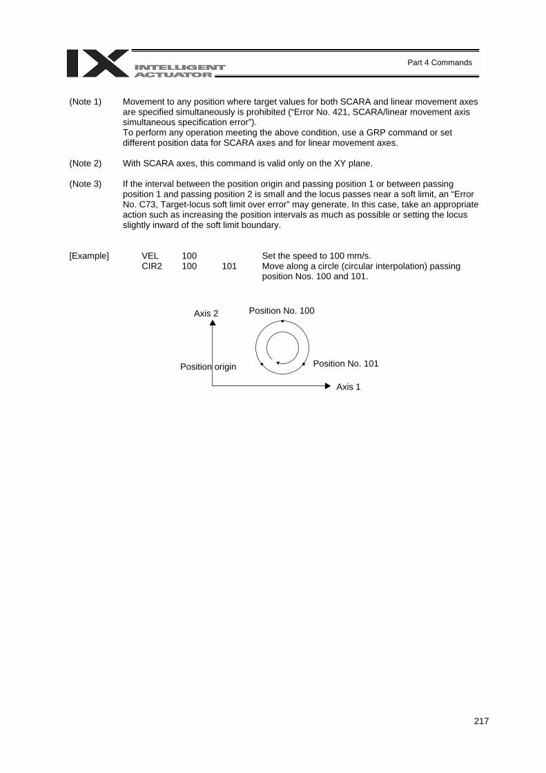
217
Part 4 Commands
(Note 1) Movement to any position where target values for both SCARA and linear movement axes
are specified simultaneously is prohibited (“Error No. 421, SCARA/linear movement axis simultaneous specification error”). To perform any operation meeting the above condition, use a GRP command or set different position data for SCARA axes and for linear movement axes.
(Note 2) With SCARA axes, this command is valid only on the XY plane.
(Note 3) If the interval between the position origin and passing position 1 or between passing position 1 and passing position 2 is small and the locus passes near a soft limit, an “Error No. C73, Target-locus soft limit over error” may generate. In this case, take an appropriate action such as increasing the position intervals as much as possible or setting the locus slightly inward of the soft limit boundary.
[Example] VEL 100 Set the speed to 100 mm/s. CIR2 100 101 Move along a circle (circular interpolation) passing
position Nos. 100 and 101.
Position No. 100
Position origin Position No. 101
Axis 1
Axis 2
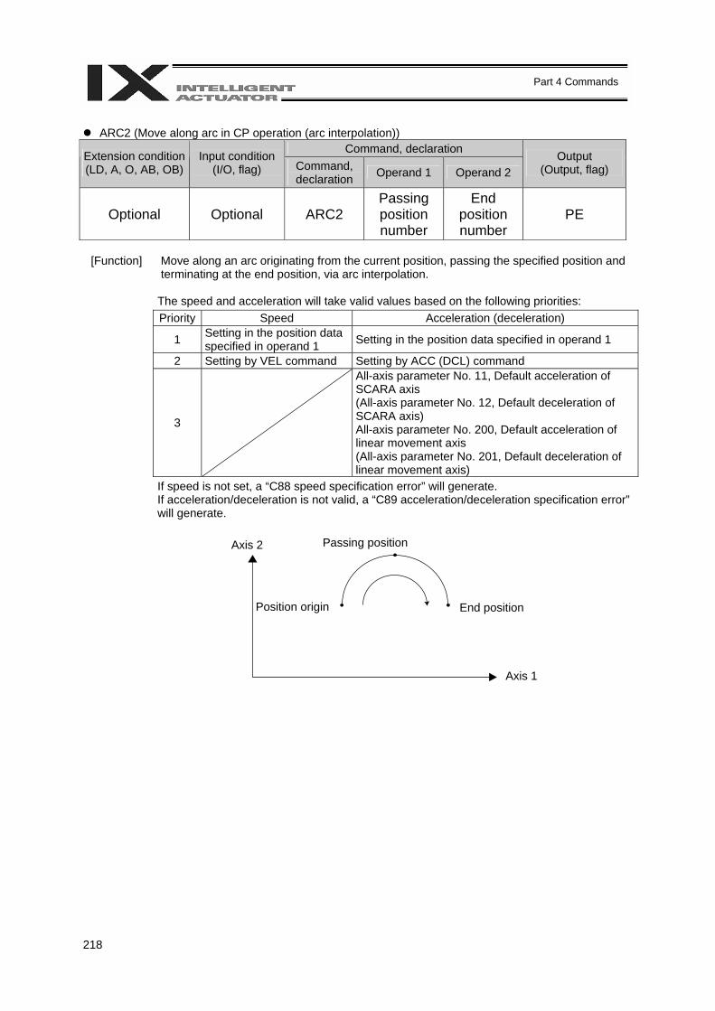
218
Part 4 Commands
ARC2 (Move along arc in CP operation (arc interpolation))
Command, declaration Extension condition (LD, A, O, AB, OB)
Input condition (I/O, flag) Command,
declaration Operand 1 Operand 2 Output
(Output, flag)
Optional Optional ARC2 Passing position number
End position number
PE
[Function] Move along an arc originating from the current position, passing the specified position and
terminating at the end position, via arc interpolation.
The speed and acceleration will take valid values based on the following priorities: Priority Speed Acceleration (deceleration)
1 Setting in the position data specified in operand 1 Setting in the position data specified in operand 1
2 Setting by VEL command Setting by ACC (DCL) command
3
All-axis parameter No. 11, Default acceleration of SCARA axis (All-axis parameter No. 12, Default deceleration of SCARA axis) All-axis parameter No. 200, Default acceleration of linear movement axis (All-axis parameter No. 201, Default deceleration of linear movement axis)
If speed is not set, a “C88 speed specification error” will generate. If acceleration/deceleration is not valid, a “C89 acceleration/deceleration specification error” will generate.
End position
Passing position
Position origin
Axis 1
Axis 2
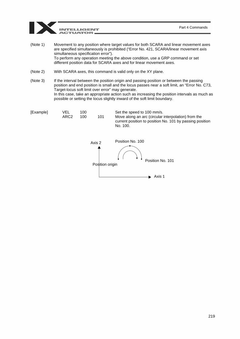
219
Part 4 Commands
(Note 1) Movement to any position where target values for both SCARA and linear movement axes
are specified simultaneously is prohibited (“Error No. 421, SCARA/linear movement axis simultaneous specification error”). To perform any operation meeting the above condition, use a GRP command or set different position data for SCARA axes and for linear movement axes.
(Note 2) With SCARA axes, this command is valid only on the XY plane.
(Note 3) If the interval between the position origin and passing position or between the passing position and end position is small and the locus passes near a soft limit, an “Error No. C73, Target-locus soft limit over error” may generate. In this case, take an appropriate action such as increasing the position intervals as much as possible or setting the locus slightly inward of the soft limit boundary.
[Example] VEL 100 Set the speed to 100 mm/s. ARC2 100 101 Move along an arc (circular interpolation) from the
current position to position No. 101 by passing position No. 100.
Position No. 100
Position origin Position No. 101
Axis 1
Axis 2
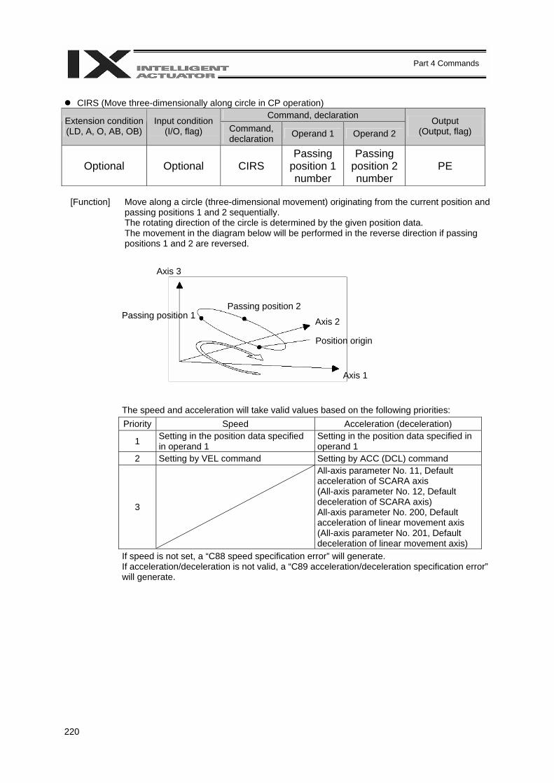
220
Part 4 Commands
CIRS (Move three-dimensionally along circle in CP operation)
Command, declaration Extension condition (LD, A, O, AB, OB)
Input condition (I/O, flag) Command,
declaration Operand 1 Operand 2 Output
(Output, flag)
Optional Optional CIRS Passing
position 1 number
Passing position 2 number
PE
[Function] Move along a circle (three-dimensional movement) originating from the current position and
passing positions 1 and 2 sequentially. The rotating direction of the circle is determined by the given position data. The movement in the diagram below will be performed in the reverse direction if passing positions 1 and 2 are reversed.
The speed and acceleration will take valid values based on the following priorities: Priority Speed Acceleration (deceleration)
1 Setting in the position data specified in operand 1
Setting in the position data specified in operand 1
2 Setting by VEL command Setting by ACC (DCL) command
3
All-axis parameter No. 11, Default acceleration of SCARA axis (All-axis parameter No. 12, Default deceleration of SCARA axis) All-axis parameter No. 200, Default acceleration of linear movement axis (All-axis parameter No. 201, Default deceleration of linear movement axis)
If speed is not set, a “C88 speed specification error” will generate. If acceleration/deceleration is not valid, a “C89 acceleration/deceleration specification error” will generate.
Axis 1
Passing position 1
Position origin
Passing position 2
Axis 3
Axis 2
221
Part 4 Commands
(Note 1) Movement to any position where target values for both SCARA and linear movement axes
are specified simultaneously is prohibited (“Error No. 421, SCARA/linear movement axis simultaneous specification error”). To perform any operation meeting the above condition, use a GRP command or set different position data for SCARA axes and for linear movement axes.
(Note 2) With SCARA axes, this command is valid on arbitrary planes in a three-dimensional space. (Axis 2 (if there are only two valid axes) or axis 3 may be selected automatically prior to axis 1 in accordance with the position data.)
(Note 3) The locus tends to shift inward as the speed increases. Minor adjustment, such as setting the position data slightly outward, may be required.
(Note 4) If the circle diameter is small with respect to the set speed, the speed may be limited. (Although increasing the acceleration/deceleration will ease the speed limitation, do not increase the acceleration/deceleration beyond the range permitted for the actuator.)
(Note 5) If the interval between the position origin and passing position 1 or between passing position 1 and passing position 2 is small and the locus passes near a soft limit, an “Error No. C73, Target-locus soft limit over error” may generate. In this case, take an appropriate action such as increasing the position intervals as much as possible or setting the locus slightly inward of the soft limit boundary.
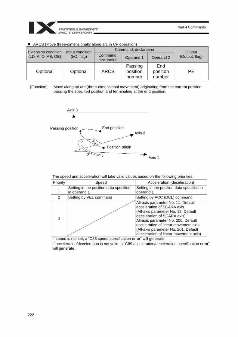
222
Part 4 Commands
ARCS (Move three-dimensionally along arc in CP operation)
Command, declaration Extension condition (LD, A, O, AB, OB)
Input condition (I/O, flag) Command,
declaration Operand 1 Operand 2 Output
(Output, flag)
Optional Optional ARCS Passing position number
End position number
PE
[Function] Move along an arc (three-dimensional movement) originating from the current position,
passing the specified position and terminating at the end position.
The speed and acceleration will take valid values based on the following priorities: Priority Speed Acceleration (deceleration)
1 Setting in the position data specified in operand 1
Setting in the position data specified in operand 1
2 Setting by VEL command Setting by ACC (DCL) command
3
All-axis parameter No. 11, Default acceleration of SCARA axis (All-axis parameter No. 12, Default deceleration of SCARA axis) All-axis parameter No. 200, Default acceleration of linear movement axis (All-axis parameter No. 201, Default deceleration of linear movement axis)
If speed is not set, a “C88 speed specification error” will generate. If acceleration/deceleration is not valid, a “C89 acceleration/deceleration specification error” will generate.
Passing position
Position origin
Z
End position
Axis 3
Axis 2
Axis 1
223
Part 4 Commands
(Note 1) Movement to any position where target values for both SCARA and linear movement axes
are specified simultaneously is prohibited (“Error No. 421, SCARA/linear movement axis simultaneous specification error”). To perform any operation meeting the above condition, use a GRP command or set different position data for SCARA axes and for linear movement axes.
(Note 2) This command is valid on arbitrary planes in a three-dimensional space. (Axis 2 (if there are only two valid axes) or axis 3 may be selected automatically prior to axis 1 in accordance with the position data.)
(Note 3) The locus tends to shift inward as the speed increases. Minor adjustment, such as setting the position data slightly outward, may be required.
(Note 4) If the arc diameter is small with respect to the set speed, the speed may be limited. (Although increasing the acceleration/deceleration will ease the speed limitation, do not increase the acceleration/deceleration beyond the range permitted for the actuator.)
(Note 5) If the interval between the position origin and passing position or between the passing position and end position is small and the locus passes near a soft limit, an “Error No. C73, Target-locus soft limit over error” may generate. In this case, take an appropriate action such as increasing the position intervals as much as possible or setting the locus slightly inward of the soft limit boundary.
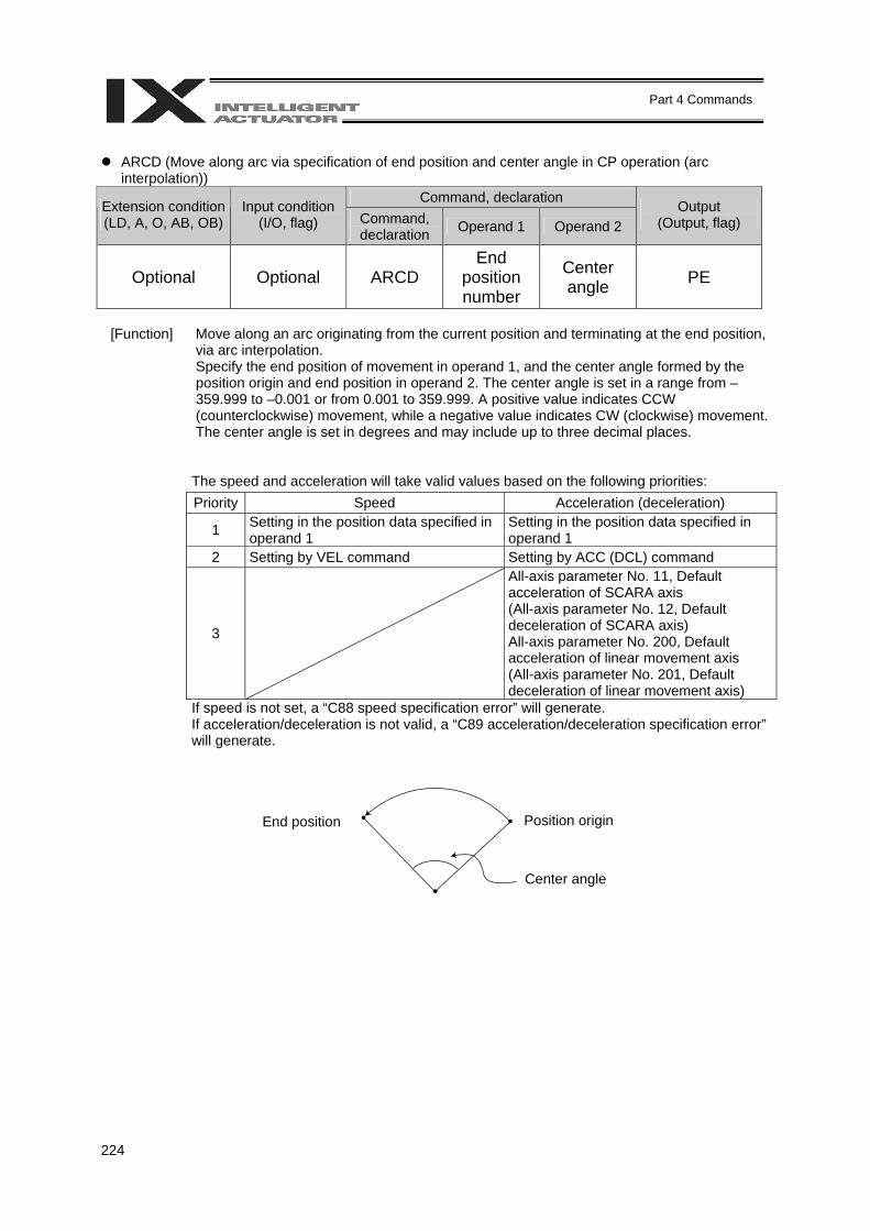
224
Part 4 Commands
ARCD (Move along arc via specification of end position and center angle in CP operation (arc
interpolation)) Command, declaration Extension condition
(LD, A, O, AB, OB) Input condition
(I/O, flag) Command, declaration Operand 1 Operand 2
Output (Output, flag)
Optional Optional ARCD End
position number
Center angle PE
[Function] Move along an arc originating from the current position and terminating at the end position,
via arc interpolation. Specify the end position of movement in operand 1, and the center angle formed by the position origin and end position in operand 2. The center angle is set in a range from –359.999 to –0.001 or from 0.001 to 359.999. A positive value indicates CCW (counterclockwise) movement, while a negative value indicates CW (clockwise) movement. The center angle is set in degrees and may include up to three decimal places.
The speed and acceleration will take valid values based on the following priorities: Priority Speed Acceleration (deceleration)
1 Setting in the position data specified in operand 1
Setting in the position data specified in operand 1
2 Setting by VEL command Setting by ACC (DCL) command
3
All-axis parameter No. 11, Default acceleration of SCARA axis (All-axis parameter No. 12, Default deceleration of SCARA axis) All-axis parameter No. 200, Default acceleration of linear movement axis (All-axis parameter No. 201, Default deceleration of linear movement axis)
If speed is not set, a “C88 speed specification error” will generate. If acceleration/deceleration is not valid, a “C89 acceleration/deceleration specification error” will generate.
End position Position origin
Center angle
225
Part 4 Commands
(Note 1) Movement to any position where target values for both SCARA and linear movement axes
are specified simultaneously is prohibited (“Error No. 421, SCARA/linear movement axis simultaneous specification error”). To perform any operation meeting the above condition, use a GRP command or set different position data for SCARA axes and for linear movement axes.
(Note 2) With SCARA axes, this command is valid only on the XY plane.
(Note 3) If the center angle is small and the locus passes near a soft limit, an “Error No. C73, Target-locus soft limit over error” may generate. In this case, take an appropriate action such as setting the locus slightly inward of the soft limit boundary. The larger the center angle, the smaller the locus error becomes.
[Example] VEL 100 Set the speed to 100 mm/s. ARCD 100 120 Move along an arc from the position origin to position
No. 100 for a center angle of 120 degrees (CCW direction).
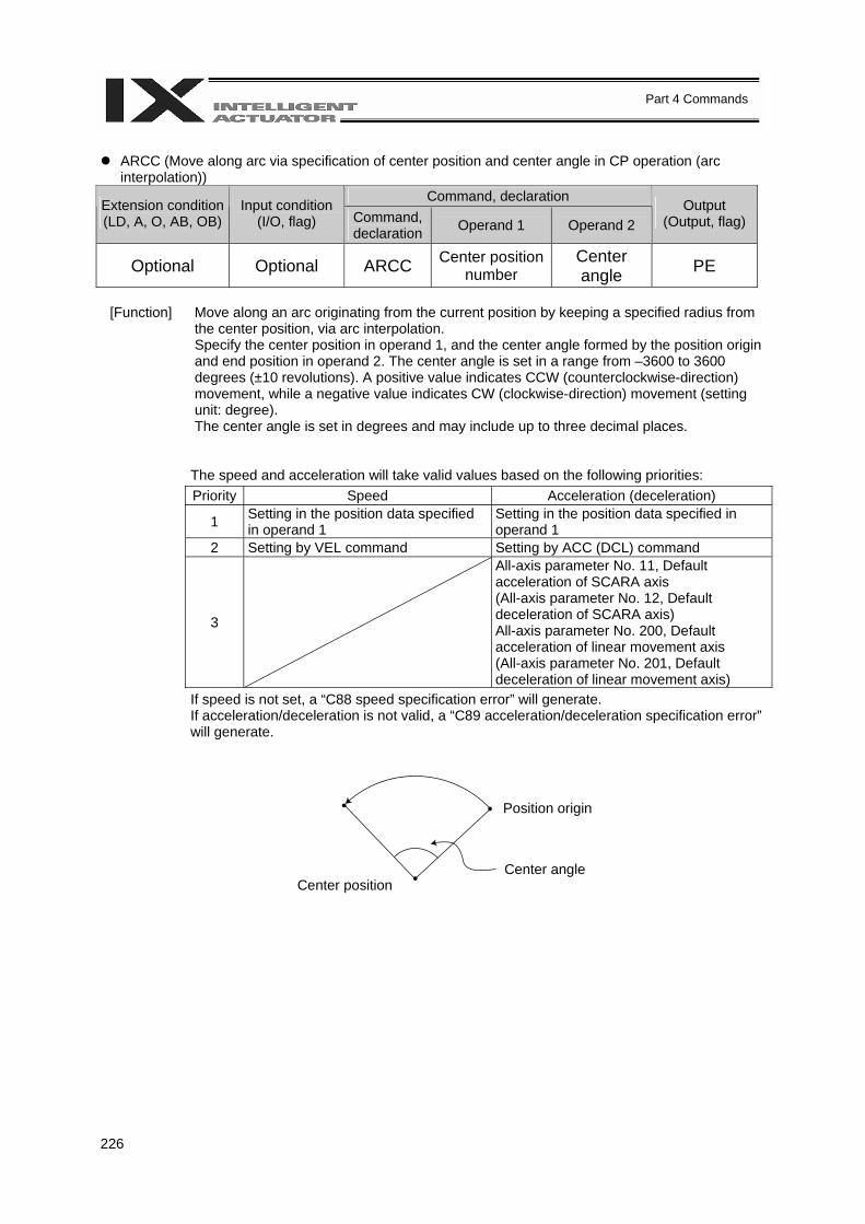
226
Part 4 Commands
ARCC (Move along arc via specification of center position and center angle in CP operation (arc
interpolation)) Command, declaration Extension condition
(LD, A, O, AB, OB) Input condition
(I/O, flag) Command, declaration Operand 1 Operand 2
Output (Output, flag)
Optional Optional ARCC Center position number
Center angle PE
[Function] Move along an arc originating from the current position by keeping a specified radius from
the center position, via arc interpolation. Specify the center position in operand 1, and the center angle formed by the position origin and end position in operand 2. The center angle is set in a range from –3600 to 3600 degrees (±10 revolutions). A positive value indicates CCW (counterclockwise-direction) movement, while a negative value indicates CW (clockwise-direction) movement (setting unit: degree). The center angle is set in degrees and may include up to three decimal places.
The speed and acceleration will take valid values based on the following priorities: Priority Speed Acceleration (deceleration)
1 Setting in the position data specified in operand 1
Setting in the position data specified in operand 1
2 Setting by VEL command Setting by ACC (DCL) command
3
All-axis parameter No. 11, Default acceleration of SCARA axis (All-axis parameter No. 12, Default deceleration of SCARA axis) All-axis parameter No. 200, Default acceleration of linear movement axis (All-axis parameter No. 201, Default deceleration of linear movement axis)
If speed is not set, a “C88 speed specification error” will generate. If acceleration/deceleration is not valid, a “C89 acceleration/deceleration specification error” will generate.
Position origin
Center angle Center position
227
Part 4 Commands
(Note 1) Movement to any position where target values for both SCARA and linear movement axes
are specified simultaneously is prohibited (“Error No. 421, SCARA/linear movement axis simultaneous specification error”). To perform any operation meeting the above condition, use a GRP command or set different position data for SCARA axes and for linear movement axes.
(Note 2) With SCARA axes, this command is valid only on the XY plane.
(Note 3) If the center angle is small and the locus passes near a soft limit, an “Error No. C73, Target-locus soft limit over error” may generate. In this case, take an appropriate action such as setting the locus slightly inward of the soft limit boundary. The larger the center angle, the smaller the locus error becomes.
[Example] VEL 100 Set the speed to 100 mm/s. ARCC 100 120 Move along an arc from the position origin for a center
angle of 120 degrees around position No. 100 being the center (CCW direction).
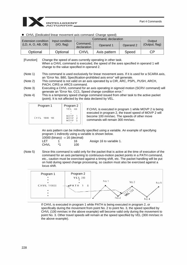
228
Part 4 Commands
CHVL (Dedicated linear movement axis command: Change speed)
Command, declaration Extension condition (LD, A, O, AB, OB)
Input condition (I/O, flag) Command,
declaration Operand 1 Operand 2 Output
(Output, flag)
Optional Optional CHVL Axis pattern Speed CP
[Function] Change the speed of axes currently operating in other task. When a CHVL command is executed, the speed of the axes specified in operand 1 will change to the value specified in operand 2.
(Note 1) This command is used exclusively for linear movement axes. If it is used for a SCARA axis, an “Error No. B80, Specification-prohibited axis error” will generate.
(Note 2) This command is not valid on an axis operated by a CIR, ARC, PSPL, PUSH, ARCH, PACH, CIRS or ARCS command.
(Note 3) Executing a CHVL command for an axis operating in sigmoid motion (SCRV command) will generate an “Error No. CC1, Speed change condition error.”
(Note 4) This is a temporary speed change command issued from other task to the active packet (point). It is not affected by the data declared by VEL.
If CHVL is executed in program 1 while MOVP 2 is being executed in program 2, the travel speed of MOVP 2 will become 100 mm/sec. The speeds of other move commands will remain 300 mm/sec.
An axis pattern can be indirectly specified using a variable. An example of specifying program 1 indirectly using a variable is shown below. 10000 (binary) → 16 (decimal)
LET 1 16 Assign 16 to variable 1. CHVL *1 100
(Note 5) Since this command is valid only for the packet that is active at the time of execution of the
command for an axis pertaining to continuous-motion packet points in a PATH command, etc., caution must be exercised against a timing shift, etc. The packet handling will be put on hold during speed change processing, so caution must also be exercised against a locus shift.
If CHVL is executed in program 1 while PATH is being executed in program 2, or specifically during the movement from point No. 2 to point No. 3, the speed specified by CHVL (100 mm/sec in the above example) will become valid only during the movement to point No. 3. Other travel speeds will remain at the speed specified by VEL (300 mm/sec in the above example).
Program 1 Program 2
Program 1 Program 2

229
Part 4 Commands
(Note 6) Override of the CHVL call task will be applied, so caution must be exercised. (Note 7) The maximum speed of the specified axis that has completed home return will be clamped
by the minimum value set in “Axis-specific parameter No. 28, Maximum operating speed of each axis” or “Axis-specific parameter No. 27, Maximum speed limited by maximum motor speed” with respect to the specified axis and related interpolation axes currently operating. To prevent the maximum speed from being limited due to the effect of other axis whose maximum speed is lower than the speed specified in the CHVL command, issue a CHVL command in multiple steps in such a way that each command applies to an axis or group of axes having the same speed. In particular, specification of a CHVL command in a separate step is recommended for a rotational movement axis.
[Example] CHVL 110000 500 ⇒ CHVL 100000 500
CHVL 10000 500
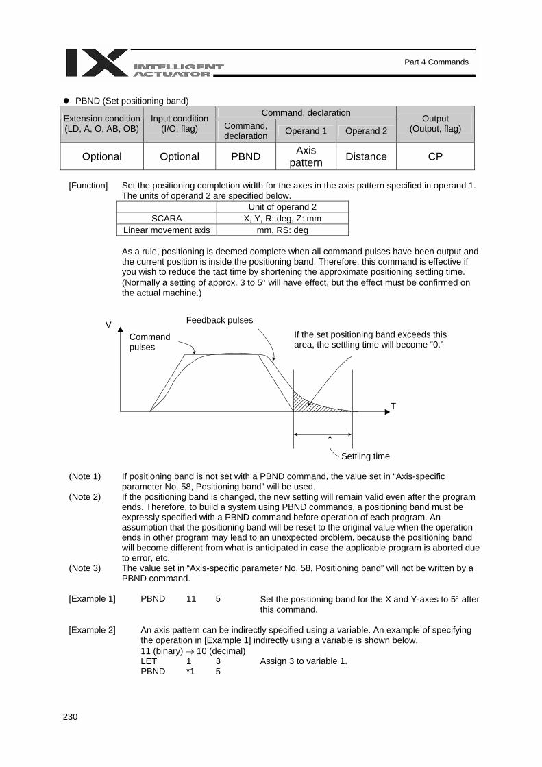
230
Part 4 Commands
PBND (Set positioning band)
Command, declaration Extension condition (LD, A, O, AB, OB)
Input condition (I/O, flag) Command,
declaration Operand 1 Operand 2 Output
(Output, flag)
Optional Optional PBND Axis pattern Distance CP
[Function] Set the positioning completion width for the axes in the axis pattern specified in operand 1.
The units of operand 2 are specified below. Unit of operand 2
SCARA X, Y, R: deg, Z: mm Linear movement axis mm, RS: deg
As a rule, positioning is deemed complete when all command pulses have been output and
the current position is inside the positioning band. Therefore, this command is effective if you wish to reduce the tact time by shortening the approximate positioning settling time. (Normally a setting of approx. 3 to 5° will have effect, but the effect must be confirmed on the actual machine.)
(Note 1) If positioning band is not set with a PBND command, the value set in “Axis-specific parameter No. 58, Positioning band” will be used.
(Note 2) If the positioning band is changed, the new setting will remain valid even after the program ends. Therefore, to build a system using PBND commands, a positioning band must be expressly specified with a PBND command before operation of each program. An assumption that the positioning band will be reset to the original value when the operation ends in other program may lead to an unexpected problem, because the positioning band will become different from what is anticipated in case the applicable program is aborted due to error, etc.
(Note 3) The value set in “Axis-specific parameter No. 58, Positioning band” will not be written by a PBND command.
[Example 1] PBND 11 5 Set the positioning band for the X and Y-axes to 5° after
this command.
[Example 2] An axis pattern can be indirectly specified using a variable. An example of specifying the operation in [Example 1] indirectly using a variable is shown below. 11 (binary) → 10 (decimal)
LET 1 3 Assign 3 to variable 1. PBND *1 5
V
T
Feedback pulses
Command pulses
If the set positioning band exceeds this area, the settling time will become “0.”
Settling time
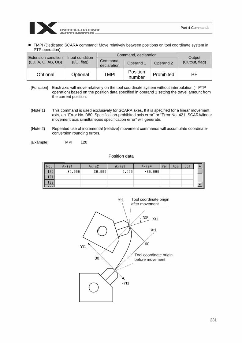
231
Part 4 Commands
TMPI (Dedicated SCARA command: Move relatively between positions on tool coordinate system in
PTP operation) Command, declaration Extension condition
(LD, A, O, AB, OB) Input condition
(I/O, flag) Command, declaration Operand 1 Operand 2
Output (Output, flag)
Optional Optional TMPI Position number Prohibited PE
[Function] Each axis will move relatively on the tool coordinate system without interpolation (= PTP
operation) based on the position data specified in operand 1 setting the travel amount from the current position.
(Note 1) This command is used exclusively for SCARA axes. If it is specified for a linear movement axis, an “Error No. B80, Specification-prohibited axis error” or “Error No. 421, SCARA/linear movement axis simultaneous specification error” will generate.
(Note 2) Repeated use of incremental (relative) movement commands will accumulate coordinate-conversion rounding errors.
[Example] TMPI 120
Position data
Tool coordinate origin after movement
Tool coordinate origin before movement
Yt1
Yt1
-Yt1
30
60
-30°
Xt1
Xt1
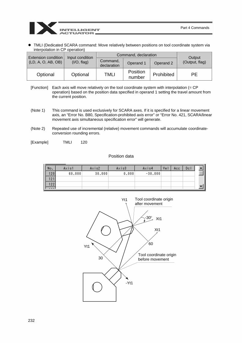
232
Part 4 Commands
TMLI (Dedicated SCARA command: Move relatively between positions on tool coordinate system via
interpolation in CP operation) Command, declaration Extension condition
(LD, A, O, AB, OB) Input condition
(I/O, flag) Command, declaration Operand 1 Operand 2
Output (Output, flag)
Optional Optional TMLI Position number Prohibited PE
[Function] Each axis will move relatively on the tool coordinate system with interpolation (= CP
operation) based on the position data specified in operand 1 setting the travel amount from the current position.
(Note 1) This command is used exclusively for SCARA axes. If it is specified for a linear movement axis, an “Error No. B80, Specification-prohibited axis error” or “Error No. 421, SCARA/linear movement axis simultaneous specification error” will generate.
(Note 2) Repeated use of incremental (relative) movement commands will accumulate coordinate-conversion rounding errors.
[Example] TMLI 120
Position data
Tool coordinate origin after movement
Tool coordinate origin before movement
Yt1
Yt1
-Yt1
30
60
-30°
Xt1
Xt1
233
Part 4 Commands
PTRQ (Change push torque limit parameter)
Command, declaration Extension condition (LD, A, O, AB, OB)
Input condition (I/O, flag) Command,
declaration Operand 1 Operand 2 Output
(Output, flag)
Optional Optional PTRQ Axis pattern Ratio CC
[Function] Change the push torque limit parameter for the axis pattern specified in operand 1 (among
SCARA axes, this command can be specified only for the Z-axis) to the value specified in operand 2. The ratio in operand 2 is set as an integer (unit: %). "Driver-card parameter No. 38: Push torque limit at positioning" can be rewritten temporarily using a PTRQ command.
(Note 1) If push torque limit is not set with a PTRQ command, the value set in "Driver-card
parameter No. 38: Push torque limit at positioning" will be used. (Note 2) If the push torque limit is changed, the new setting will remain valid even after the program
ends. Therefore, to build a system using PTRQ commands, a push torque limit must be expressly specified with a PTRQ command before operation of each program. An assumption that the push torque limit will be reset to the original value when the operation ends in other program may lead to an unexpected problem, because the push torque limit will become different from what is anticipated in case the applicable program is aborted due to error, etc.
(Note 3) The new value set with a PTRQ command will become invalid after a power-ON reset or software reset.
(Note 4) The value set in "Driver-card parameter No. 38: Push torque limit at positioning" (in the main CPU flash memory (nonvolatile memory)) will not be written by a PTRQ command.
[Example] PTRQ 100 50 Change the push torque limit parameter for the Z-axis to 50%.
PAPR 50 20 Set the push-motion approach distance to 50 mm and push-motion approach speed to 20 mm/sec.
MOVP 10 Move to position No. 10. PUSH 11 Perform push motion operation at position No. 11.
234
Part 4 Commands
CIR (Move along circle in CP operation)
Command, declaration Extension condition (LD, A, O, AB, OB)
Input condition (I/O, flag) Command,
declaration Operand 1 Operand 2 Output
(Output, flag)
Optional Optional CIR Passing
position 1 number
Passing position 2 number
PE
[Function] Move along a circle originating from the current position and passing the positions specified in
operands 1 and 2. Therefore, reversing the settings of operands 1 and 2 will implement a circular movement in the reverse direction. The output will turn OFF at the start of circular movement, and turn ON when the movement is complete. Difference from CIR2:
CIR processing resembles moving along a polygon with a PATH command, while CIR2 actually performs arc interpolation. Select an applicable command by considering the characteristics of each command. (Normally CIR2 is used.)
(Note 1) Movement to any position where target values for both SCARA and linear movement axes are
specified simultaneously is prohibited (“Error No. 421, SCARA/linear movement axis simultaneous specification error”). To perform any operation meeting the above condition, use a GRP command or set different position data for SCARA axes and for linear movement axes.
(Note 2) If the division angle is set to “0” with a DEG command (division angle is calculated automatically based on priority speed setting), the speed set in the data at passing position 1 or speed set by a VEL command will be used (former is given priority). The speed set in the data at passing position 2 will have no meaning.
(Note 3) If the division angle is set to a value other than “0” with a DEG command (normal division angle), the speed specified in the target position data will be used. (The speed set by a VEL command will become valid if position data is not specified.) In the case of circular movement, the axes will return from passing position 2 to the start position at the speed declared by a VEL command. Therefore, a VEL command must always be used with a CIR command.
(Note 4) The acceleration is selected in the order of the acceleration in the data at passing position 1, followed by the value set in an ACC command, and the value in “All-axis parameter No. 11, Default acceleration of SCARA axis” or “All-axis parameter No. 200, Default acceleration of linear movement axis.” The deceleration will become the same value as the valid acceleration selected above. Therefore, the deceleration in the data at passing position 1 and the acceleration/deceleration in the data at passing position 2 will not have any meaning.
(Note 5) This command is valid on arbitrary orthogonal planes. (Depending on the position data, axis 2 may be selected automatically and preferentially before axis 1.)
(Note 6) If the interval between the position origin and passing position 1 or between passing position 1 and passing position 2 is small and the locus passes near a soft limit, an “Error No. C73, Target-locus soft limit over error” may generate. In this case, take an appropriate action such as increasing the position intervals as much as possible or setting the locus slightly inward of the soft limit boundary.
[Example 1] VEL 100 Set the speed to 100 mm/s. CIR 100 101 Move along a circle from the current position by passing
positions 100 and 101 sequentially. [Example 2] VEL 100 Set the speed to 100 mm/s. LET 1 5 Assign 5 to variable 1. LET 2 6 Assign 6 to variable 2. CIR *1 *2 Move along a circle from the current position by passing
the contents of variables 1 and 2 (positions 5 and 6) sequentially.
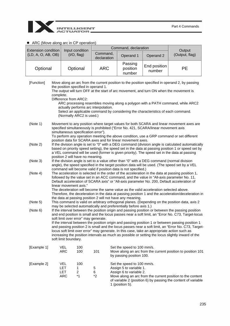
235
Part 4 Commands
ARC (Move along arc in CP operation)
Command, declaration Extension condition (LD, A, O, AB, OB)
Input condition (I/O, flag) Command,
declaration Operand 1 Operand 2 Output
(Output, flag)
Optional Optional ARC Passing position number
End position number PE
[Function] Move along an arc from the current position to the position specified in operand 2, by passing
the position specified in operand 1. The output will turn OFF at the start of arc movement, and turn ON when the movement is complete. Difference from ARC2:
ARC processing resembles moving along a polygon with a PATH command, while ARC2 actually performs arc interpolation. Select an applicable command by considering the characteristics of each command. (Normally ARC2 is used.)
(Note 1) Movement to any position where target values for both SCARA and linear movement axes are
specified simultaneously is prohibited (“Error No. 421, SCARA/linear movement axis simultaneous specification error”). To perform any operation meeting the above condition, use a GRP command or set different position data for SCARA axes and for linear movement axes.
(Note 2) If the division angle is set to “0” with a DEG command (division angle is calculated automatically based on priority speed setting), the speed set in the data at passing position 1 or speed set by a VEL command will be used (former is given priority). The speed set in the data at passing position 2 will have no meaning.
(Note 3) If the division angle is set to a value other than “0” with a DEG command (normal division angle), the speed specified in the target position data will be used. (The speed set by a VEL command will become valid if position data is not specified.)
(Note 4) The acceleration is selected in the order of the acceleration in the data at passing position 1, followed by the value set in an ACC command, and the value in “All-axis parameter No. 11, Default acceleration of SCARA axis” or “All-axis parameter No. 200, Default acceleration of linear movement axis.” The deceleration will become the same value as the valid acceleration selected above. Therefore, the deceleration in the data at passing position 1 and the acceleration/deceleration in the data at passing position 2 will not have any meaning.
(Note 5) This command is valid on arbitrary orthogonal planes. (Depending on the position data, axis 2 may be selected automatically and preferentially before axis 1.)
(Note 6) If the interval between the position origin and passing position or between the passing position and end position is small and the locus passes near a soft limit, an “Error No. C73, Target-locus soft limit over error” may generate. If the interval between the position origin and passing position 1 or between passing position 1 and passing position 2 is small and the locus passes near a soft limit, an “Error No. C73, Target-locus soft limit over error” may generate. In this case, take an appropriate action such as increasing the position intervals as much as possible or setting the locus slightly inward of the soft limit boundary.
[Example 1] VEL 100 Set the speed to 100 mm/s. ARC 100 101 Move along an arc from the current position to position 101
by passing position 100. [Example 2] VEL 100 Set the speed to 100 mm/s. LET 1 5 Assign 5 to variable 1. LET 2 6 Assign 6 to variable 2. ARC *1 *2 Move along an arc from the current position to the content
of variable 2 (position 6) by passing the content of variable 1 (position 5).
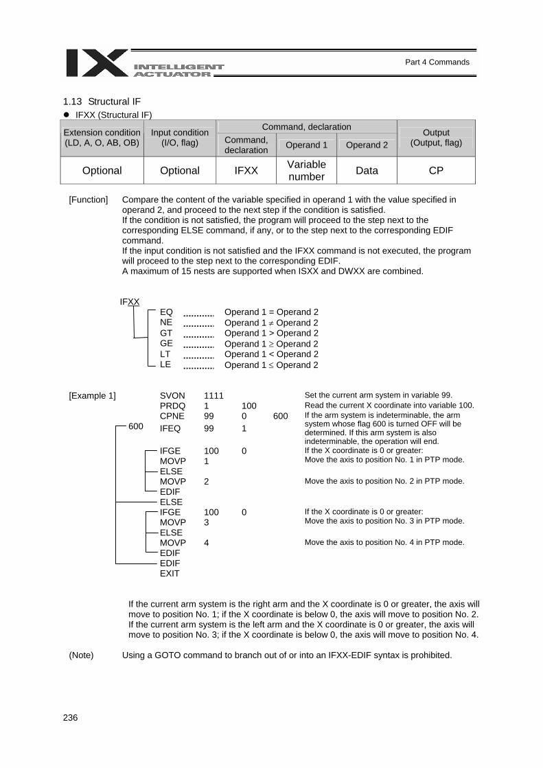
236
Part 4 Commands
1.13 Structural IF
IFXX (Structural IF) Command, declaration Extension condition
(LD, A, O, AB, OB) Input condition
(I/O, flag) Command, declaration Operand 1 Operand 2
Output (Output, flag)
Optional Optional IFXX Variable number Data CP
[Function] Compare the content of the variable specified in operand 1 with the value specified in
operand 2, and proceed to the next step if the condition is satisfied. If the condition is not satisfied, the program will proceed to the step next to the corresponding ELSE command, if any, or to the step next to the corresponding EDIF command. If the input condition is not satisfied and the IFXX command is not executed, the program will proceed to the step next to the corresponding EDIF. A maximum of 15 nests are supported when ISXX and DWXX are combined.
IFXX EQ Operand 1 = Operand 2 NE Operand 1 ≠ Operand 2 GT Operand 1 > Operand 2 GE Operand 1 ≥ Operand 2 LT Operand 1 < Operand 2 LE Operand 1 ≤ Operand 2
[Example 1] SVON 1111 Set the current arm system in variable 99. PRDQ 1 100 Read the current X coordinate into variable 100. CPNE 99 0 600 600 IFEQ
99
1
If the arm system is indeterminable, the arm system whose flag 600 is turned OFF will be determined. If this arm system is also indeterminable, the operation will end.
IFGE 100 0 MOVP 1
If the X coordinate is 0 or greater: Move the axis to position No. 1 in PTP mode.
ELSE MOVP 2 Move the axis to position No. 2 in PTP mode. EDIF ELSE IFGE 100 0 MOVP 3
If the X coordinate is 0 or greater: Move the axis to position No. 3 in PTP mode.
ELSE MOVP 4 Move the axis to position No. 4 in PTP mode. EDIF EDIF EXIT
If the current arm system is the right arm and the X coordinate is 0 or greater, the axis will move to position No. 1; if the X coordinate is below 0, the axis will move to position No. 2. If the current arm system is the left arm and the X coordinate is 0 or greater, the axis will move to position No. 3; if the X coordinate is below 0, the axis will move to position No. 4.
(Note) Using a GOTO command to branch out of or into an IFXX-EDIF syntax is prohibited.
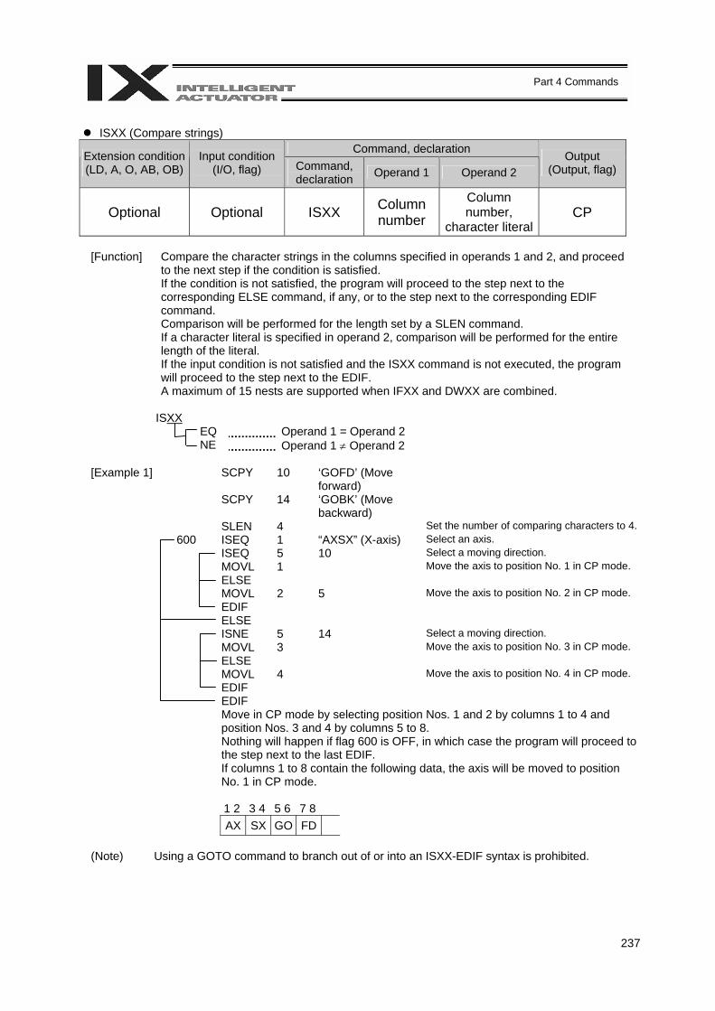
237
Part 4 Commands
ISXX (Compare strings)
Command, declaration Extension condition (LD, A, O, AB, OB)
Input condition (I/O, flag) Command,
declaration Operand 1 Operand 2 Output
(Output, flag)
Optional Optional ISXX Column number
Column number,
character literal CP
[Function] Compare the character strings in the columns specified in operands 1 and 2, and proceed
to the next step if the condition is satisfied. If the condition is not satisfied, the program will proceed to the step next to the corresponding ELSE command, if any, or to the step next to the corresponding EDIF command. Comparison will be performed for the length set by a SLEN command. If a character literal is specified in operand 2, comparison will be performed for the entire length of the literal. If the input condition is not satisfied and the ISXX command is not executed, the program will proceed to the step next to the EDIF. A maximum of 15 nests are supported when IFXX and DWXX are combined.
ISXX EQ Operand 1 = Operand 2 NE Operand 1 ≠ Operand 2
[Example 1] SCPY
10
‘GOFD’ (Move forward)
SCPY
14
‘GOBK’ (Move backward)
SLEN 4 Set the number of comparing characters to 4. 600 ISEQ 1 “AXSX” (X-axis) Select an axis. ISEQ 5 10 Select a moving direction. MOVL 1 Move the axis to position No. 1 in CP mode. ELSE MOVL 2 5 Move the axis to position No. 2 in CP mode. EDIF ELSE ISNE 5 14 Select a moving direction. MOVL 3 Move the axis to position No. 3 in CP mode. ELSE MOVL 4 Move the axis to position No. 4 in CP mode. EDIF EDIF Move in CP mode by selecting position Nos. 1 and 2 by columns 1 to 4 and
position Nos. 3 and 4 by columns 5 to 8. Nothing will happen if flag 600 is OFF, in which case the program will proceed to the step next to the last EDIF. If columns 1 to 8 contain the following data, the axis will be moved to position No. 1 in CP mode.
1 2 3 4 5 6 7 8 AX SX GO FD
(Note) Using a GOTO command to branch out of or into an ISXX-EDIF syntax is prohibited.

238
Part 4 Commands
ELSE (Else)
Command, declaration Extension condition (LD, A, O, AB, OB)
Input condition (I/O, flag) Command,
declaration Operand 1 Operand 2 Output
(Output, flag)
Prohibited Prohibited ELSE Prohibited Prohibited CP
[Function] An ELSE command is used arbitrarily in conjunction with an IFXX or ISXX command to
declare the command part to be executed when the condition is not satisfied.
[Example 1] Refer to the sections on IFXX and ISXX.
EDIF (End IFXX) Command, declaration Extension condition
(LD, A, O, AB, OB) Input condition
(I/O, flag) Command, declaration Operand 1 Operand 2
Output (Output, flag)
Prohibited Prohibited EDIF Prohibited Prohibited CP
[Function] Declare the end of an IFXX or ISXX command.
[Example 1] Refer to the sections on IFXX and ISXX.
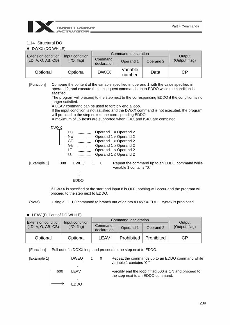
239
Part 4 Commands
1.14 Structural DO
DWXX (DO WHILE) Command, declaration Extension condition
(LD, A, O, AB, OB) Input condition
(I/O, flag) Command, declaration Operand 1 Operand 2
Output (Output, flag)
Optional Optional DWXX Variable number Data CP
[Function] Compare the content of the variable specified in operand 1 with the value specified in
operand 2, and execute the subsequent commands up to EDDO while the condition is satisfied. The program will proceed to the step next to the corresponding EDDO if the condition is no longer satisfied. A LEAV command can be used to forcibly end a loop. If the input condition is not satisfied and the DWXX command is not executed, the program will proceed to the step next to the corresponding EDDO. A maximum of 15 nests are supported when IFXX and ISXX are combined.
DWXX EQ Operand 1 = Operand 2 NE Operand 1 ≠ Operand 2 GT Operand 1 > Operand 2 GE Operand 1 ≥ Operand 2 LT Operand 1 < Operand 2 LE Operand 1 ≤ Operand 2
[Example 1] 008 DWEQ 1 0 Repeat the command up to an EDDO command while
variable 1 contains “0.” : : EDDO
If DWXX is specified at the start and input 8 is OFF, nothing will occur and the program will proceed to the step next to EDDO.
(Note) Using a GOTO command to branch out of or into a DWXX-EDDO syntax is prohibited.
LEAV (Pull out of DO WHILE) Command, declaration Extension condition
(LD, A, O, AB, OB) Input condition
(I/O, flag) Command, declaration Operand 1 Operand 2
Output (Output, flag)
Optional Optional LEAV Prohibited Prohibited CP
[Function] Pull out of a DOXX loop and proceed to the step next to EDDO. [Example 1] DWEQ 1 0 Repeat the commands up to an EDDO command while
variable 1 contains “0.” : 600 LEAV Forcibly end the loop if flag 600 is ON and proceed to
the step next to an EDDO command. : EDDO
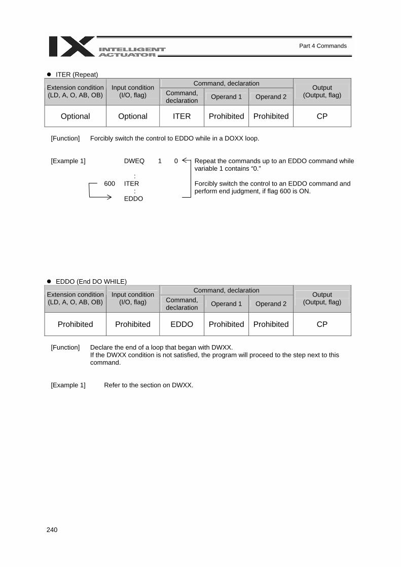
240
Part 4 Commands
ITER (Repeat)
Command, declaration Extension condition (LD, A, O, AB, OB)
Input condition (I/O, flag) Command,
declaration Operand 1 Operand 2 Output
(Output, flag)
Optional Optional ITER Prohibited Prohibited CP
[Function] Forcibly switch the control to EDDO while in a DOXX loop.
[Example 1] DWEQ 1 0 Repeat the commands up to an EDDO command while variable 1 contains “0.”
: 600 ITER :
Forcibly switch the control to an EDDO command and perform end judgment, if flag 600 is ON.
EDDO
EDDO (End DO WHILE) Command, declaration Extension condition
(LD, A, O, AB, OB) Input condition
(I/O, flag) Command, declaration Operand 1 Operand 2
Output (Output, flag)
Prohibited Prohibited EDDO Prohibited Prohibited CP
[Function] Declare the end of a loop that began with DWXX.
If the DWXX condition is not satisfied, the program will proceed to the step next to this command.
[Example 1] Refer to the section on DWXX.
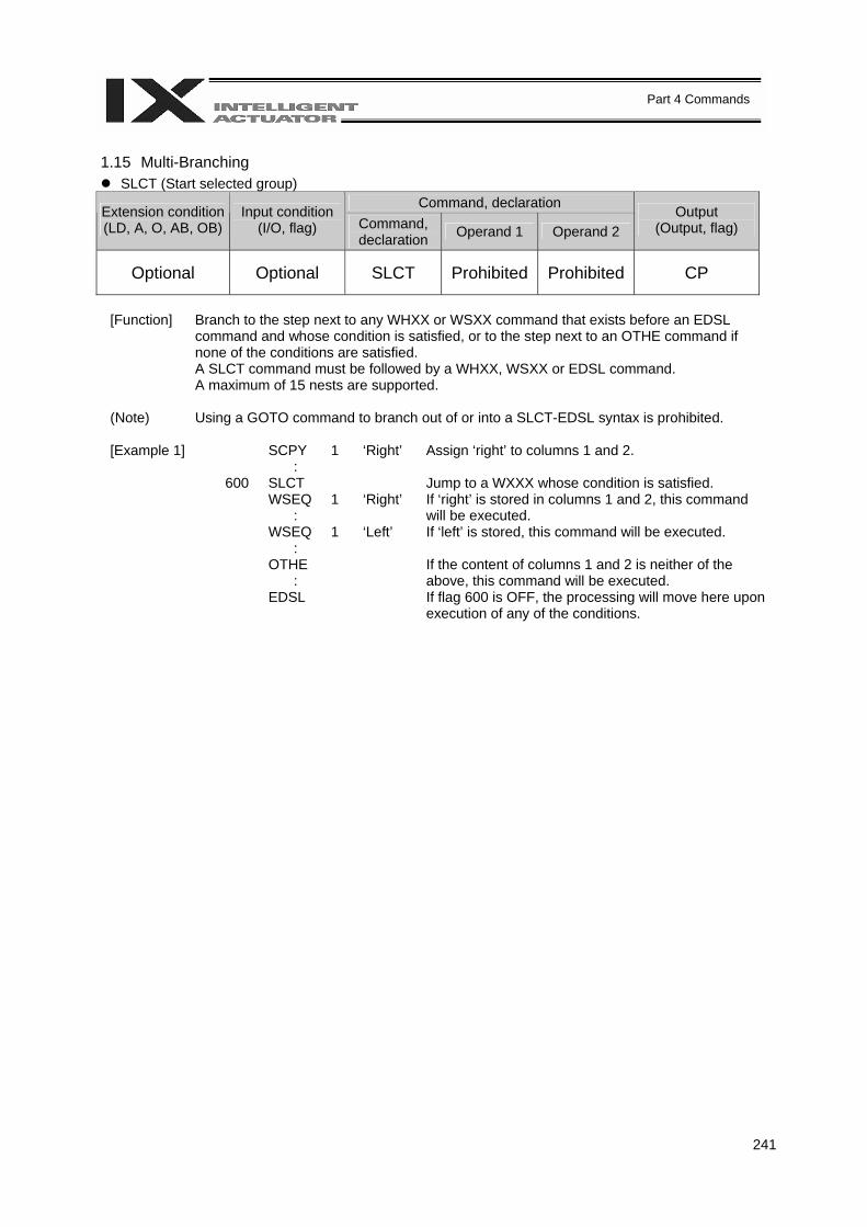
241
Part 4 Commands
1.15 Multi-Branching
SLCT (Start selected group) Command, declaration Extension condition
(LD, A, O, AB, OB) Input condition
(I/O, flag) Command, declaration Operand 1 Operand 2
Output (Output, flag)
Optional Optional SLCT Prohibited Prohibited CP
[Function] Branch to the step next to any WHXX or WSXX command that exists before an EDSL
command and whose condition is satisfied, or to the step next to an OTHE command if none of the conditions are satisfied. A SLCT command must be followed by a WHXX, WSXX or EDSL command. A maximum of 15 nests are supported.
(Note) Using a GOTO command to branch out of or into a SLCT-EDSL syntax is prohibited.
[Example 1] SCPY 1 ‘Right’ Assign ‘right’ to columns 1 and 2. : 600 SLCT Jump to a WXXX whose condition is satisfied. WSEQ 1 ‘Right’ :
If ‘right’ is stored in columns 1 and 2, this command will be executed.
WSEQ 1 ‘Left’ :
If ‘left’ is stored, this command will be executed.
OTHE :
If the content of columns 1 and 2 is neither of the above, this command will be executed.
EDSL If flag 600 is OFF, the processing will move here upon execution of any of the conditions.
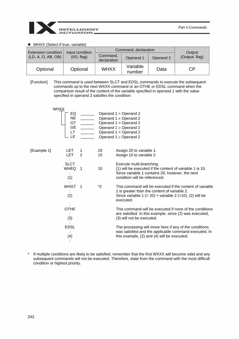
242
Part 4 Commands
WHXX (Select if true; variable)
Command, declaration Extension condition (LD, A, O, AB, OB)
Input condition (I/O, flag) Command,
declaration Operand 1 Operand 2 Output
(Output, flag)
Optional Optional WHXX Variable number Data CP
[Function] This command is used between SLCT and EDSL commands to execute the subsequent
commands up to the next WXXX command or an OTHE or EDSL command when the comparison result of the content of the variable specified in operand 1 with the value specified in operand 2 satisfies the condition.
WHXX EQ Operand 1 = Operand 2 NE Operand 1 ≠ Operand 2 GT Operand 1 > Operand 2 GE Operand 1 ≥ Operand 2 LT Operand 1 < Operand 2 LE Operand 1 ≤ Operand 2
[Example 1] LET 1 20 Assign 20 to variable 1. LET 2 10 Assign 10 to variable 2. : SLCT Execute multi-branching. WHEQ 1 10 : (1)
(1) will be executed if the content of variable 1 is 10. Since variable 1 contains 20, however, the next condition will be referenced.
: WHGT 1 *2 : (2)
This command will be executed if the content of variable 1 is greater than the content of variable 2. Since variable 1 (= 20) > variable 2 (=10), (2) will be executed.
: OTHE : (3)
This command will be executed if none of the conditions are satisfied. In this example, since (2) was executed, (3) will not be executed.
: EDSL : (4) :
The processing will move here if any of the conditions was satisfied and the applicable command executed. In this example, (2) and (4) will be executed.
* If multiple conditions are likely to be satisfied, remember that the first WXXX will become valid and any
subsequent commands will not be executed. Therefore, state from the command with the most difficult condition or highest priority.
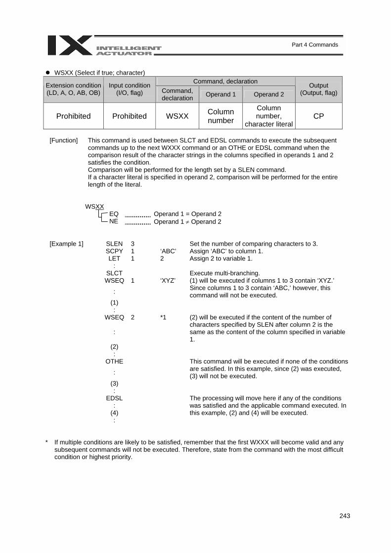
243
Part 4 Commands
WSXX (Select if true; character)
Command, declaration Extension condition (LD, A, O, AB, OB)
Input condition (I/O, flag) Command,
declaration Operand 1 Operand 2 Output
(Output, flag)
Prohibited Prohibited WSXX Column number
Column number,
character literal CP
[Function] This command is used between SLCT and EDSL commands to execute the subsequent
commands up to the next WXXX command or an OTHE or EDSL command when the comparison result of the character strings in the columns specified in operands 1 and 2 satisfies the condition. Comparison will be performed for the length set by a SLEN command. If a character literal is specified in operand 2, comparison will be performed for the entire length of the literal.
WSXX EQ Operand 1 = Operand 2 NE Operand 1 ≠ Operand 2
[Example 1] SLEN 3 Set the number of comparing characters to 3. SCPY 1 ‘ABC’ Assign ‘ABC’ to column 1. LET 1 2 Assign 2 to variable 1. : SLCT Execute multi-branching. WSEQ 1 ‘XYZ’ :
(1) will be executed if columns 1 to 3 contain ‘XYZ.’ Since columns 1 to 3 contain ‘ABC,’ however, this command will not be executed.
(1) : WSEQ 2 *1
:
(2) will be executed if the content of the number of characters specified by SLEN after column 2 is the same as the content of the column specified in variable 1.
(2) : OTHE :
This command will be executed if none of the conditions are satisfied. In this example, since (2) was executed, (3) will not be executed.
(3) : EDSL : (4)
The processing will move here if any of the conditions was satisfied and the applicable command executed. In this example, (2) and (4) will be executed.
: * If multiple conditions are likely to be satisfied, remember that the first WXXX will become valid and any
subsequent commands will not be executed. Therefore, state from the command with the most difficult condition or highest priority.
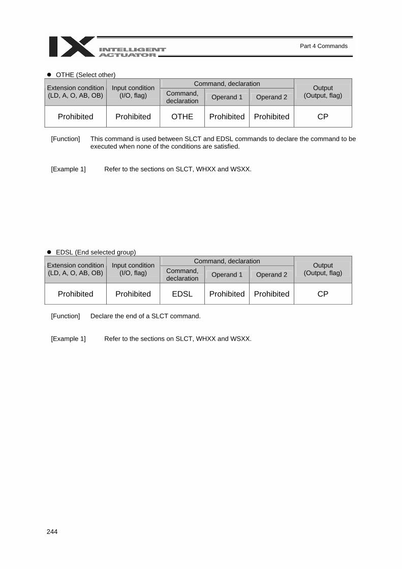
244
Part 4 Commands
OTHE (Select other)
Command, declaration Extension condition (LD, A, O, AB, OB)
Input condition (I/O, flag) Command,
declaration Operand 1 Operand 2 Output
(Output, flag)
Prohibited Prohibited OTHE Prohibited Prohibited CP
[Function] This command is used between SLCT and EDSL commands to declare the command to be
executed when none of the conditions are satisfied.
[Example 1] Refer to the sections on SLCT, WHXX and WSXX.
EDSL (End selected group) Command, declaration Extension condition
(LD, A, O, AB, OB) Input condition
(I/O, flag) Command, declaration Operand 1 Operand 2
Output (Output, flag)
Prohibited Prohibited EDSL Prohibited Prohibited CP
[Function] Declare the end of a SLCT command.
[Example 1] Refer to the sections on SLCT, WHXX and WSXX.
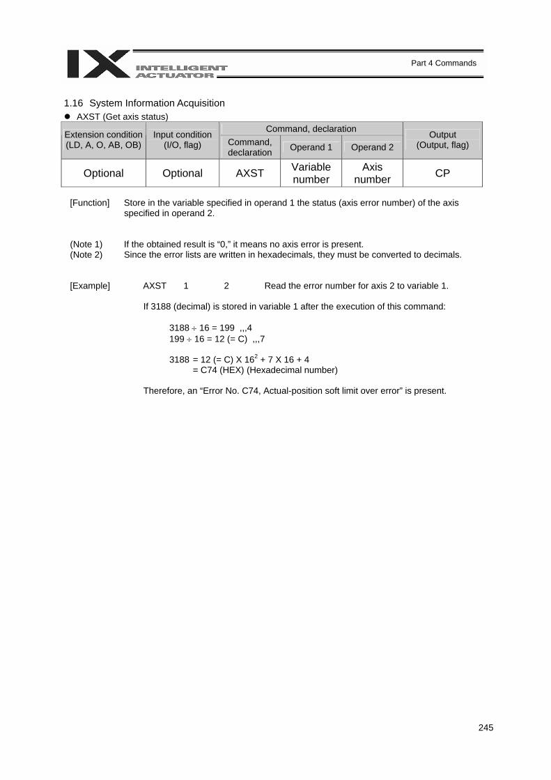
245
Part 4 Commands
1.16 System Information Acquisition
AXST (Get axis status) Command, declaration Extension condition
(LD, A, O, AB, OB) Input condition
(I/O, flag) Command, declaration Operand 1 Operand 2
Output (Output, flag)
Optional Optional AXST Variable number
Axis number CP
[Function] Store in the variable specified in operand 1 the status (axis error number) of the axis
specified in operand 2.
(Note 1) If the obtained result is “0,” it means no axis error is present. (Note 2) Since the error lists are written in hexadecimals, they must be converted to decimals.
[Example] AXST 1 2 Read the error number for axis 2 to variable 1.
If 3188 (decimal) is stored in variable 1 after the execution of this command:
3188 ÷ 16 = 199 ,,,4 199 ÷ 16 = 12 (= C) ,,,7 3188 = 12 (= C) X 162 + 7 X 16 + 4 = C74 (HEX) (Hexadecimal number)
Therefore, an “Error No. C74, Actual-position soft limit over error” is present.

246
Part 4 Commands
PGST (Get program status)
Command, declaration Extension condition (LD, A, O, AB, OB)
Input condition (I/O, flag) Command,
declaration Operand 1 Operand 2 Output
(Output, flag)
Optional Optional PGST Variable number
Program number CP
[Function] Store in the variable specified in operand 1 the status (program error number) of the
program specified in operand 2.
(Note 1) If the obtained result is “0,” it means no program error is present. (Note 2) Although the error lists are written in hexadecimals, the status to be stored (program error
number) is a decimal. Therefore, the decimal program error numbers must be converted to hexadecimals.
[Example] PGST 1 2 Read the error number for program No. 2 to variable 1.
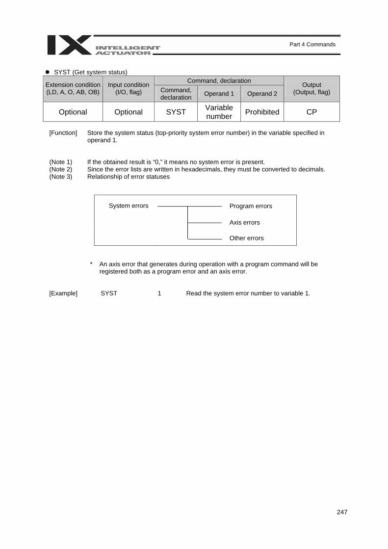
247
Part 4 Commands
SYST (Get system status)
Command, declaration Extension condition (LD, A, O, AB, OB)
Input condition (I/O, flag) Command,
declaration Operand 1 Operand 2 Output
(Output, flag)
Optional Optional SYST Variable number Prohibited CP
[Function] Store the system status (top-priority system error number) in the variable specified in
operand 1.
(Note 1) If the obtained result is “0,” it means no system error is present. (Note 2) Since the error lists are written in hexadecimals, they must be converted to decimals. (Note 3) Relationship of error statuses
System errors Program errors
Axis errors
Other errors
* An axis error that generates during operation with a program command will be registered both as a program error and an axis error.
[Example] SYST 1 Read the system error number to variable 1.
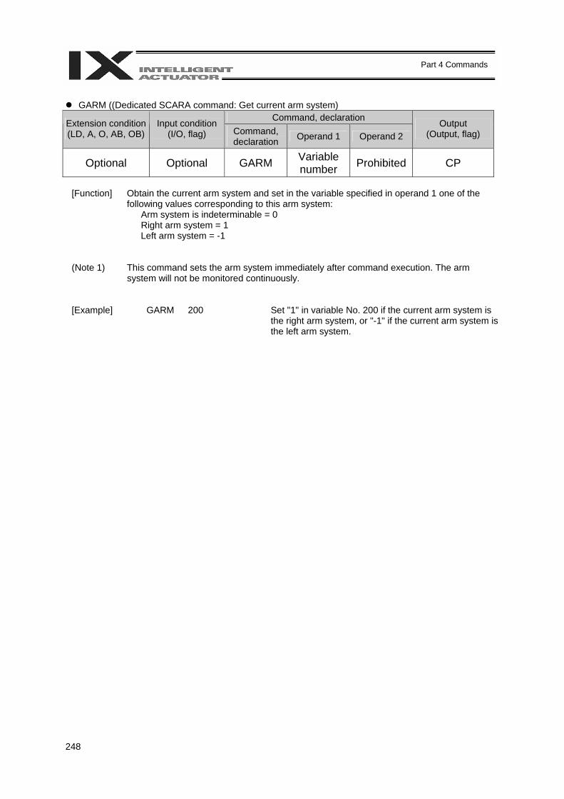
248
Part 4 Commands
GARM ((Dedicated SCARA command: Get current arm system)
Command, declaration Extension condition (LD, A, O, AB, OB)
Input condition (I/O, flag) Command,
declaration Operand 1 Operand 2 Output
(Output, flag)
Optional Optional GARM Variable number Prohibited CP
[Function] Obtain the current arm system and set in the variable specified in operand 1 one of the
following values corresponding to this arm system: Arm system is indeterminable = 0 Right arm system = 1 Left arm system = -1
(Note 1) This command sets the arm system immediately after command execution. The arm system will not be monitored continuously.
[Example] GARM 200 Set "1" in variable No. 200 if the current arm system is the right arm system, or "-1" if the current arm system is the left arm system.
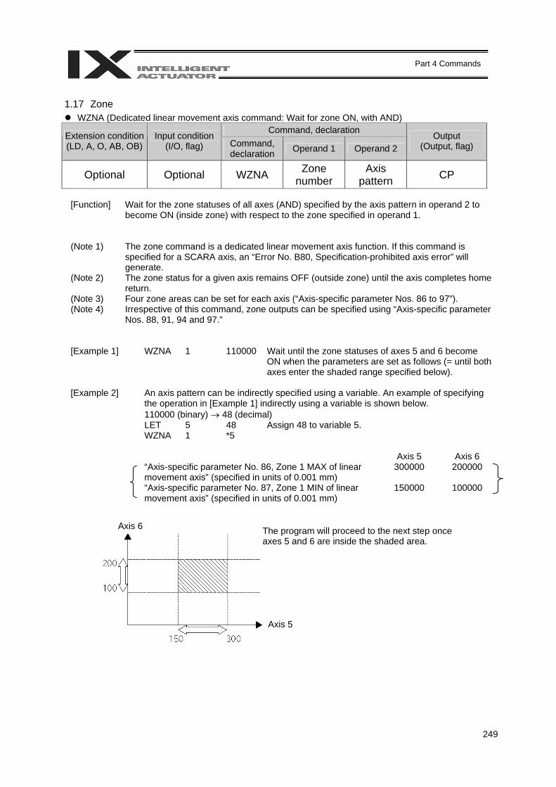
249
Part 4 Commands
1.17 Zone
WZNA (Dedicated linear movement axis command: Wait for zone ON, with AND) Command, declaration Extension condition
(LD, A, O, AB, OB) Input condition
(I/O, flag) Command, declaration Operand 1 Operand 2
Output (Output, flag)
Optional Optional WZNA Zone number
Axis pattern CP
[Function] Wait for the zone statuses of all axes (AND) specified by the axis pattern in operand 2 to
become ON (inside zone) with respect to the zone specified in operand 1.
(Note 1) The zone command is a dedicated linear movement axis function. If this command is specified for a SCARA axis, an “Error No. B80, Specification-prohibited axis error” will generate.
(Note 2) The zone status for a given axis remains OFF (outside zone) until the axis completes home return.
(Note 3) Four zone areas can be set for each axis (“Axis-specific parameter Nos. 86 to 97”). (Note 4) Irrespective of this command, zone outputs can be specified using “Axis-specific parameter
Nos. 88, 91, 94 and 97.”
[Example 1] WZNA 1 110000 Wait until the zone statuses of axes 5 and 6 become ON when the parameters are set as follows (= until both axes enter the shaded range specified below).
[Example 2] An axis pattern can be indirectly specified using a variable. An example of specifying
the operation in [Example 1] indirectly using a variable is shown below. 110000 (binary) → 48 (decimal)
LET 5 48 Assign 48 to variable 5. WZNA 1 *5 Axis 5 Axis 6 “Axis-specific parameter No. 86, Zone 1 MAX of linear
movement axis” (specified in units of 0.001 mm) 300000 200000
“Axis-specific parameter No. 87, Zone 1 MIN of linear movement axis” (specified in units of 0.001 mm)
150000 100000
The program will proceed to the next step once axes 5 and 6 are inside the shaded area.
Axis 6
Axis 5
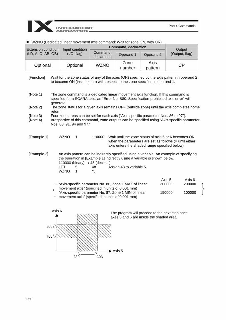
250
Part 4 Commands
WZNO (Dedicated linear movement axis command: Wait for zone ON, with OR)
Command, declaration Extension condition (LD, A, O, AB, OB)
Input condition (I/O, flag) Command,
declaration Operand 1 Operand 2 Output
(Output, flag)
Optional Optional WZNO Zone number
Axis pattern CP
[Function] Wait for the zone status of any of the axes (OR) specified by the axis pattern in operand 2
to become ON (inside zone) with respect to the zone specified in operand 1.
(Note 1) The zone command is a dedicated linear movement axis function. If this command is specified for a SCARA axis, an “Error No. B80, Specification-prohibited axis error” will generate.
(Note 2) The zone status for a given axis remains OFF (outside zone) until the axis completes home return.
(Note 3) Four zone areas can be set for each axis (“Axis-specific parameter Nos. 86 to 97”). (Note 4) Irrespective of this command, zone outputs can be specified using “Axis-specific parameter
Nos. 88, 91, 94 and 97.”
[Example 1] WZNO 1 110000 Wait until the zone status of axis 5 or 6 becomes ON when the parameters are set as follows (= until either axis enters the shaded range specified below).
[Example 2] An axis pattern can be indirectly specified using a variable. An example of specifying
the operation in [Example 1] indirectly using a variable is shown below. 110000 (binary) → 48 (decimal)
LET 5 48 Assign 48 to variable 5. WZNO 1 *5 Axis 5 Axis 6 “Axis-specific parameter No. 86, Zone 1 MAX of linear
movement axis” (specified in units of 0.001 mm) 300000 200000
“Axis-specific parameter No. 87, Zone 1 MIN of linear movement axis” (specified in units of 0.001 mm)
150000 100000
The program will proceed to the next step once axes 5 and 6 are inside the shaded area.
Axis 6
Axis 5
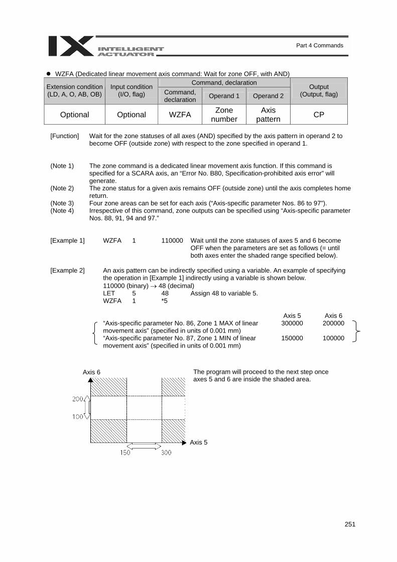
251
Part 4 Commands
WZFA (Dedicated linear movement axis command: Wait for zone OFF, with AND)
Command, declaration Extension condition (LD, A, O, AB, OB)
Input condition (I/O, flag) Command,
declaration Operand 1 Operand 2 Output
(Output, flag)
Optional Optional WZFA Zone number
Axis pattern CP
[Function] Wait for the zone statuses of all axes (AND) specified by the axis pattern in operand 2 to
become OFF (outside zone) with respect to the zone specified in operand 1.
(Note 1) The zone command is a dedicated linear movement axis function. If this command is specified for a SCARA axis, an “Error No. B80, Specification-prohibited axis error” will generate.
(Note 2) The zone status for a given axis remains OFF (outside zone) until the axis completes home return.
(Note 3) Four zone areas can be set for each axis (“Axis-specific parameter Nos. 86 to 97”). (Note 4) Irrespective of this command, zone outputs can be specified using “Axis-specific parameter
Nos. 88, 91, 94 and 97.”
[Example 1] WZFA 1 110000 Wait until the zone statuses of axes 5 and 6 become OFF when the parameters are set as follows (= until both axes enter the shaded range specified below).
[Example 2] An axis pattern can be indirectly specified using a variable. An example of specifying
the operation in [Example 1] indirectly using a variable is shown below. 110000 (binary) → 48 (decimal)
LET 5 48 Assign 48 to variable 5. WZFA 1 *5 Axis 5 Axis 6 “Axis-specific parameter No. 86, Zone 1 MAX of linear
movement axis” (specified in units of 0.001 mm) 300000 200000
“Axis-specific parameter No. 87, Zone 1 MIN of linear movement axis” (specified in units of 0.001 mm)
150000 100000
The program will proceed to the next step once axes 5 and 6 are inside the shaded area.
Axis 6
Axis 5
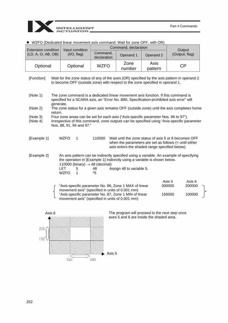
252
Part 4 Commands
WZFO (Dedicated linear movement axis command: Wait for zone OFF, with OR)
Command, declaration Extension condition (LD, A, O, AB, OB)
Input condition (I/O, flag) Command,
declaration Operand 1 Operand 2 Output
(Output, flag)
Optional Optional WZFO Zone number
Axis pattern CP
[Function] Wait for the zone status of any of the axes (OR) specified by the axis pattern in operand 2
to become OFF (outside zone) with respect to the zone specified in operand 1.
(Note 1) The zone command is a dedicated linear movement axis function. If this command is specified for a SCARA axis, an “Error No. B80, Specification-prohibited axis error” will generate.
(Note 2) The zone status for a given axis remains OFF (outside zone) until the axis completes home return.
(Note 3) Four zone areas can be set for each axis (“Axis-specific parameter Nos. 86 to 97”). (Note 4) Irrespective of this command, zone outputs can be specified using “Axis-specific parameter
Nos. 88, 91, 94 and 97.”
[Example 1] WZFO 1 110000 Wait until the zone status of axis 5 or 6 becomes OFF when the parameters are set as follows (= until either axis enters the shaded range specified below).
[Example 2] An axis pattern can be indirectly specified using a variable. An example of specifying
the operation in [Example 1] indirectly using a variable is shown below. 110000 (binary) → 48 (decimal)
LET 5 48 Assign 48 to variable 5. WZFO 1 *5 Axis 5 Axis 6 “Axis-specific parameter No. 86, Zone 1 MAX of linear
movement axis” (specified in units of 0.001 mm) 300000 200000
“Axis-specific parameter No. 87, Zone 1 MIN of linear movement axis” (specified in units of 0.001 mm)
150000 100000
The program will proceed to the next step once axes 5 and 6 are inside the shaded area.
Axis 6
Axis 5

253
Part 4 Commands
1.18 Communication
OPEN (Open channel) Command, declaration Extension condition
(LD, A, O, AB, OB) Input condition
(I/O, flag) Command, declaration Operand 1 Operand 2
Output (Output, flag)
Optional Optional OPEN Channel number Prohibited CP
[Function] Open the channel specified in operand 1.
The specified channel will be enabled to send/receive hereafter. Prior to executing this command, a SCHA command must be used to set an end character.
[Example] SCHA 10 OPEN 1 Specify 10 (= LF) as the end character.
Open channel 1.
Note: If “OPEN 0” is executed, the teaching connector (D-sub, 25-pin) will be disconnected. (This is because channel 0 is shared by the teaching pendant/PC software.)
CLOS (Close channel) Command, declaration Extension condition
(LD, A, O, AB, OB) Input condition
(I/O, flag) Command, declaration Operand 1 Operand 2
Output (Output, flag)
Optional Optional CLOS Channel number Prohibited CP
[Function] Close the channel specified in operand 1.
The specified channel will be disabled to send/receive hereafter.
[Example] CLOS 1 Close channel 1. LET 1 2 CLOS *1 Assign 2 to variable 1. Close the content of variable 1 (channel 2).
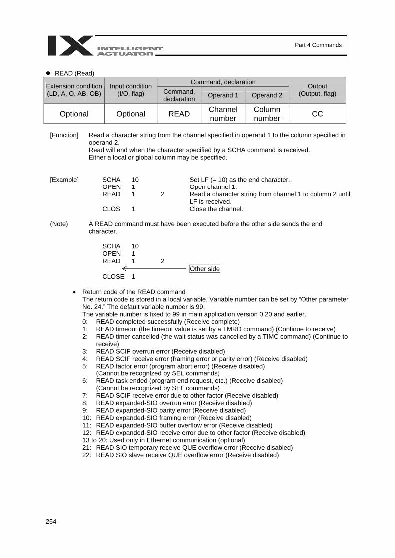
254
Part 4 Commands
READ (Read)
Command, declaration Extension condition (LD, A, O, AB, OB)
Input condition (I/O, flag) Command,
declaration Operand 1 Operand 2 Output
(Output, flag)
Optional Optional READ Channel number
Column number CC
[Function] Read a character string from the channel specified in operand 1 to the column specified in
operand 2. Read will end when the character specified by a SCHA command is received. Either a local or global column may be specified.
[Example] SCHA 10 Set LF (= 10) as the end character. OPEN 1 Open channel 1. READ 1 2 Read a character string from channel 1 to column 2 until
LF is received. CLOS 1 Close the channel. (Note) A READ command must have been executed before the other side sends the end
character. SCHA 10 OPEN 1 READ 1 2 Other side CLOSE 1
• Return code of the READ command
The return code is stored in a local variable. Variable number can be set by “Other parameter No. 24.” The default variable number is 99. The variable number is fixed to 99 in main application version 0.20 and earlier. 0: READ completed successfully (Receive complete) 1: READ timeout (the timeout value is set by a TMRD command) (Continue to receive) 2: READ timer cancelled (the wait status was cancelled by a TIMC command) (Continue to
receive) 3: READ SCIF overrun error (Receive disabled) 4: READ SCIF receive error (framing error or parity error) (Receive disabled) 5: READ factor error (program abort error) (Receive disabled)
(Cannot be recognized by SEL commands) 6: READ task ended (program end request, etc.) (Receive disabled)
(Cannot be recognized by SEL commands) 7: READ SCIF receive error due to other factor (Receive disabled) 8: READ expanded-SIO overrun error (Receive disabled) 9: READ expanded-SIO parity error (Receive disabled) 10: READ expanded-SIO framing error (Receive disabled) 11: READ expanded-SIO buffer overflow error (Receive disabled) 12: READ expanded-SIO receive error due to other factor (Receive disabled) 13 to 20: Used only in Ethernet communication (optional) 21: READ SIO temporary receive QUE overflow error (Receive disabled) 22: READ SIO slave receive QUE overflow error (Receive disabled)
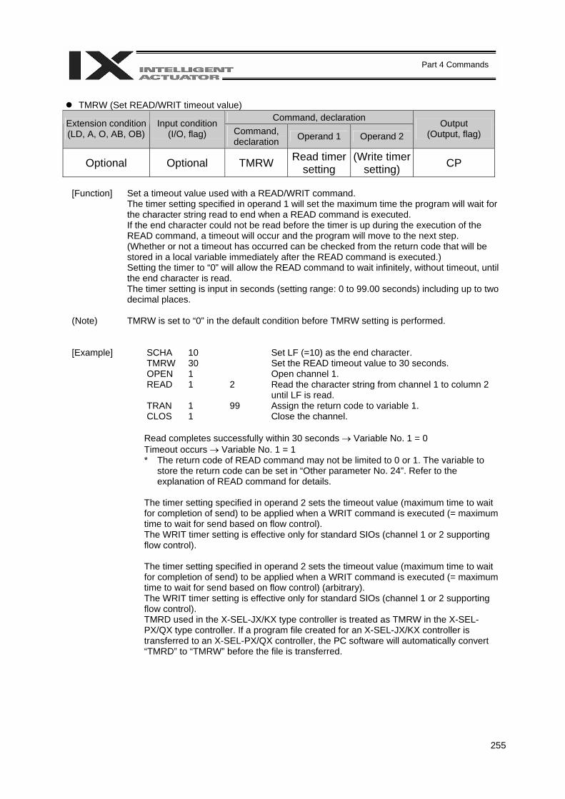
255
Part 4 Commands
TMRW (Set READ/WRIT timeout value)
Command, declaration Extension condition (LD, A, O, AB, OB)
Input condition (I/O, flag) Command,
declaration Operand 1 Operand 2 Output
(Output, flag)
Optional Optional TMRW Read timer setting
(Write timer setting) CP
[Function] Set a timeout value used with a READ/WRIT command.
The timer setting specified in operand 1 will set the maximum time the program will wait for the character string read to end when a READ command is executed. If the end character could not be read before the timer is up during the execution of the READ command, a timeout will occur and the program will move to the next step. (Whether or not a timeout has occurred can be checked from the return code that will be stored in a local variable immediately after the READ command is executed.) Setting the timer to “0” will allow the READ command to wait infinitely, without timeout, until the end character is read. The timer setting is input in seconds (setting range: 0 to 99.00 seconds) including up to two decimal places.
(Note) TMRW is set to “0” in the default condition before TMRW setting is performed.
[Example] SCHA 10 Set LF (=10) as the end character. TMRW 30 Set the READ timeout value to 30 seconds. OPEN 1 Open channel 1. READ 1 2 Read the character string from channel 1 to column 2
until LF is read. TRAN 1 99 Assign the return code to variable 1. CLOS 1 Close the channel.
Read completes successfully within 30 seconds → Variable No. 1 = 0 Timeout occurs → Variable No. 1 = 1 * The return code of READ command may not be limited to 0 or 1. The variable to
store the return code can be set in “Other parameter No. 24”. Refer to the explanation of READ command for details.
The timer setting specified in operand 2 sets the timeout value (maximum time to wait for completion of send) to be applied when a WRIT command is executed (= maximum time to wait for send based on flow control). The WRIT timer setting is effective only for standard SIOs (channel 1 or 2 supporting flow control). The timer setting specified in operand 2 sets the timeout value (maximum time to wait for completion of send) to be applied when a WRIT command is executed (= maximum time to wait for send based on flow control) (arbitrary). The WRIT timer setting is effective only for standard SIOs (channel 1 or 2 supporting flow control). TMRD used in the X-SEL-JX/KX type controller is treated as TMRW in the X-SEL-PX/QX type controller. If a program file created for an X-SEL-JX/KX controller is transferred to an X-SEL-PX/QX controller, the PC software will automatically convert “TMRD” to “TMRW” before the file is transferred.
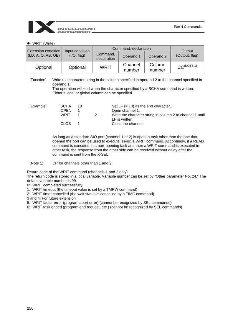
256
Part 4 Commands
WRIT (Write)
Command, declaration Extension condition (LD, A, O, AB, OB)
Input condition (I/O, flag) Command,
declaration Operand 1 Operand 2 Output
(Output, flag)
Optional Optional WRIT Channel number
Column number CC(NOTE 1)
[Function] Write the character string in the column specified in operand 2 to the channel specified in
operand 1. The operation will end when the character specified by a SCHA command is written. Either a local or global column can be specified.
[Example] SCHA 10 Set LF (= 10) as the end character. OPEN 1 Open channel 1. WRIT 1 2 Write the character string in column 2 to channel 1 until
LF is written. CLOS 1 Close the channel.
As long as a standard SIO port (channel 1 or 2) is open, a task other than the one that opened the port can be used to execute (send) a WRIT command. Accordingly, if a READ command is executed in a port-opening task and then a WRIT command is executed in other task, the response from the other side can be received without delay after the command is sent from the X-SEL.
(Note 1) CP for channels other than 1 and 2.
Return code of the WRIT command (channels 1 and 2 only) The return code is stored in a local variable. Variable number can be set by “Other parameter No. 24.” The default variable number is 99. 0: WRIT completed successfully 1: WRIT timeout (the timeout value is set by a TMRW command) 2: WRIT timer cancelled (the wait status is cancelled by a TIMC command) 3 and 4: For future extension 5: WRIT factor error (program abort error) (cannot be recognized by SEL commands) 6: WRIT task ended (program end request, etc.) (cannot be recognized by SEL commands)

257
Part 4 Commands
SCHA (Set end character)
Command, declaration Extension condition (LD, A, O, AB, OB)
Input condition (I/O, flag) Command,
declaration Operand 1 Operand 2 Output
(Output, flag)
Optional Optional SCHA Character code Prohibited CP
[Function] Set the end character to be used by a READ or WRIT command.
Any character from 0 to 255 (character code used in BASIC, etc.) can be specified.
[Example] Refer to the sections on READ and WRIT commands.
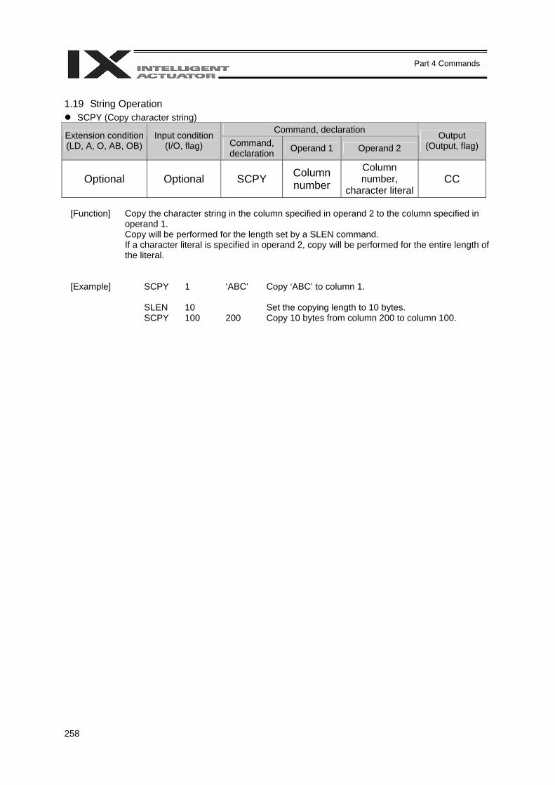
258
Part 4 Commands
1.19 String Operation
SCPY (Copy character string) Command, declaration Extension condition
(LD, A, O, AB, OB) Input condition
(I/O, flag) Command, declaration Operand 1 Operand 2
Output (Output, flag)
Optional Optional SCPY Column number
Column number,
character literal CC
[Function] Copy the character string in the column specified in operand 2 to the column specified in
operand 1. Copy will be performed for the length set by a SLEN command. If a character literal is specified in operand 2, copy will be performed for the entire length of the literal.
[Example] SCPY 1 ‘ABC’ Copy ‘ABC’ to column 1. SLEN 10 Set the copying length to 10 bytes. SCPY 100 200 Copy 10 bytes from column 200 to column 100.
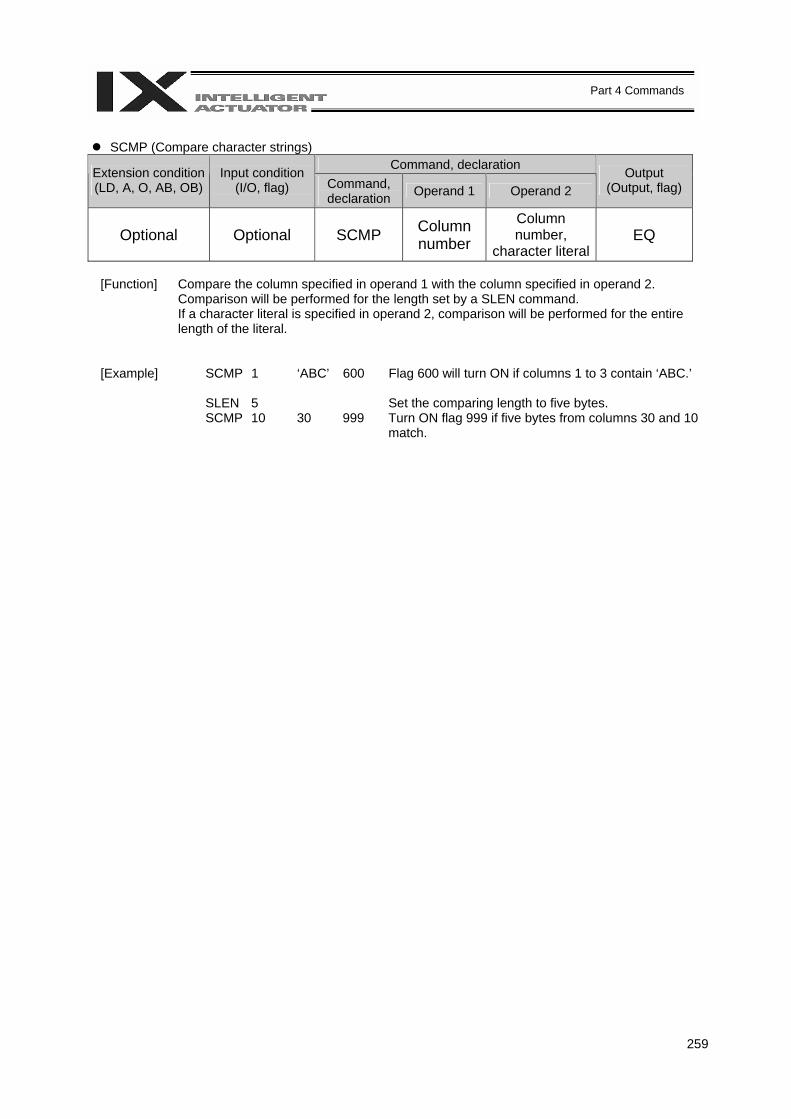
259
Part 4 Commands
SCMP (Compare character strings)
Command, declaration Extension condition (LD, A, O, AB, OB)
Input condition (I/O, flag) Command,
declaration Operand 1 Operand 2 Output
(Output, flag)
Optional Optional SCMP Column number
Column number,
character literal EQ
[Function] Compare the column specified in operand 1 with the column specified in operand 2.
Comparison will be performed for the length set by a SLEN command. If a character literal is specified in operand 2, comparison will be performed for the entire length of the literal.
[Example] SCMP 1 ‘ABC’ 600 Flag 600 will turn ON if columns 1 to 3 contain ‘ABC.’ SLEN 5 Set the comparing length to five bytes. SCMP 10 30 999 Turn ON flag 999 if five bytes from columns 30 and 10
match.
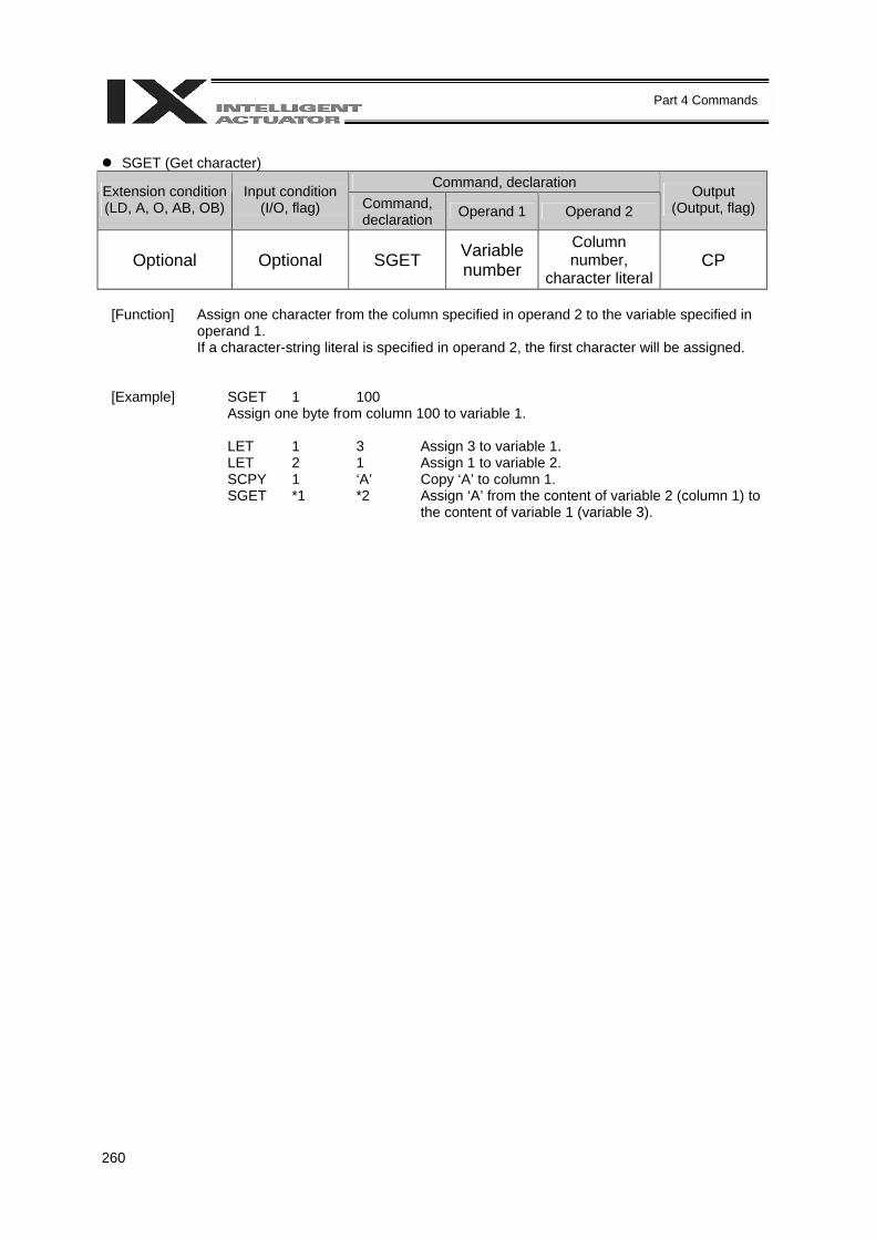
260
Part 4 Commands
SGET (Get character)
Command, declaration Extension condition (LD, A, O, AB, OB)
Input condition (I/O, flag) Command,
declaration Operand 1 Operand 2 Output
(Output, flag)
Optional Optional SGET Variable number
Column number,
character literal CP
[Function] Assign one character from the column specified in operand 2 to the variable specified in
operand 1. If a character-string literal is specified in operand 2, the first character will be assigned.
[Example] SGET 1 100 Assign one byte from column 100 to variable 1. LET 1 3 Assign 3 to variable 1. LET 2 1 Assign 1 to variable 2. SCPY 1 ‘A’ Copy ‘A’ to column 1. SGET *1 *2 Assign ‘A’ from the content of variable 2 (column 1) to
the content of variable 1 (variable 3).

261
Part 4 Commands
SPUT (Set character)
Command, declaration Extension condition (LD, A, O, AB, OB)
Input condition (I/O, flag) Command,
declaration Operand 1 Operand 2 Output
(Output, flag)
Optional Optional SPUT Column number Data CP
[Function] Set the data specified in operand 2 in the column specified in operand 1.
[Example] SPUT 5 10 Set 10 (LF) in column 5. LET 1 100 Assign 100 to variable 1. LET 2 50 Assign 50 to variable 2. SPUT *1 *2 Set the content of variable 2 (50 (‘2’)) in the content of
variable 1 (column 100).
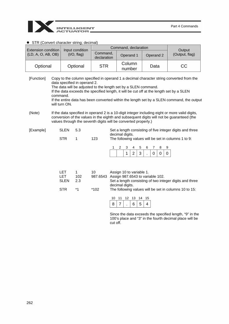
262
Part 4 Commands
STR (Convert character string; decimal)
Command, declaration Extension condition (LD, A, O, AB, OB)
Input condition (I/O, flag) Command,
declaration Operand 1 Operand 2 Output
(Output, flag)
Optional Optional STR Column number Data CC
[Function] Copy to the column specified in operand 1 a decimal character string converted from the
data specified in operand 2. The data will be adjusted to the length set by a SLEN command. If the data exceeds the specified length, it will be cut off at the length set by a SLEN command. If the entire data has been converted within the length set by a SLEN command, the output will turn ON.
(Note) If the data specified in operand 2 is a 10-digit integer including eight or more valid digits,
conversion of the values in the eighth and subsequent digits will not be guaranteed (the values through the seventh digits will be converted properly.)
[Example] SLEN 5.3 Set a length consisting of five integer digits and three
decimal digits. STR 1 123 The following values will be set in columns 1 to 9:
1 2 3 4 5 6 7 8 9
1 2 3 . 0 0 0 LET 1 10 Assign 10 to variable 1. LET 102 987.6543 Assign 987.6543 to variable 102. SLEN 2.3 Set a length consisting of two integer digits and three
decimal digits. STR *1 *102 The following values will be set in columns 10 to 15:
10 11 12 13 14 15
8 7 . 6 5 4 Since the data exceeds the specified length, “9” in the 100’s place and “3” in the fourth decimal place will be cut off.
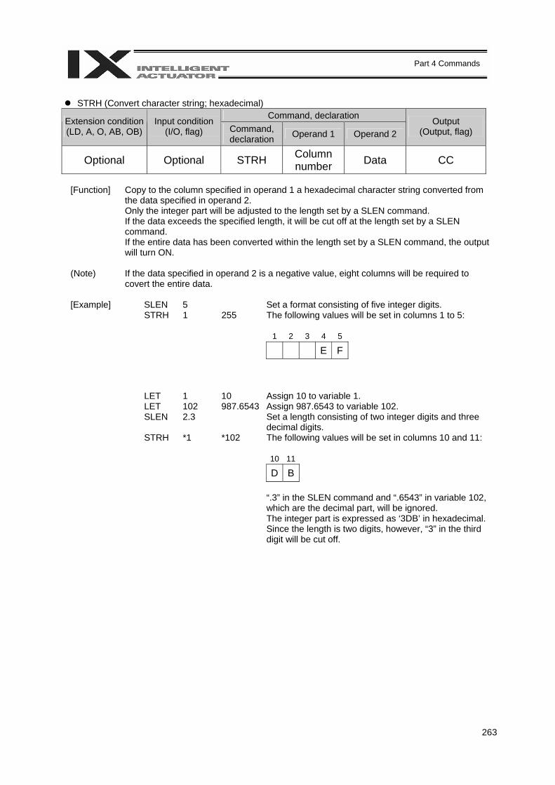
263
Part 4 Commands
STRH (Convert character string; hexadecimal)
Command, declaration Extension condition (LD, A, O, AB, OB)
Input condition (I/O, flag) Command,
declaration Operand 1 Operand 2 Output
(Output, flag)
Optional Optional STRH Column number Data CC
[Function] Copy to the column specified in operand 1 a hexadecimal character string converted from
the data specified in operand 2. Only the integer part will be adjusted to the length set by a SLEN command. If the data exceeds the specified length, it will be cut off at the length set by a SLEN command. If the entire data has been converted within the length set by a SLEN command, the output will turn ON.
(Note) If the data specified in operand 2 is a negative value, eight columns will be required to
covert the entire data. [Example] SLEN 5 Set a format consisting of five integer digits. STRH 1 255 The following values will be set in columns 1 to 5:
1 2 3 4 5
E F LET 1 10 Assign 10 to variable 1. LET 102 987.6543 Assign 987.6543 to variable 102. SLEN 2.3 Set a length consisting of two integer digits and three
decimal digits. STRH *1 *102 The following values will be set in columns 10 and 11:
10 11
D B “.3” in the SLEN command and “.6543” in variable 102, which are the decimal part, will be ignored. The integer part is expressed as ‘3DB’ in hexadecimal. Since the length is two digits, however, “3” in the third digit will be cut off.
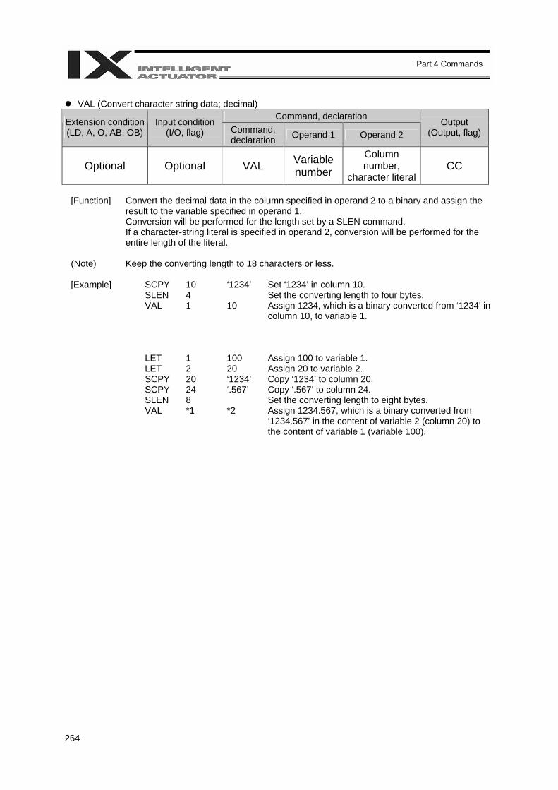
264
Part 4 Commands
VAL (Convert character string data; decimal)
Command, declaration Extension condition (LD, A, O, AB, OB)
Input condition (I/O, flag) Command,
declaration Operand 1 Operand 2 Output
(Output, flag)
Optional Optional VAL Variable number
Column number,
character literal CC
[Function] Convert the decimal data in the column specified in operand 2 to a binary and assign the
result to the variable specified in operand 1. Conversion will be performed for the length set by a SLEN command. If a character-string literal is specified in operand 2, conversion will be performed for the entire length of the literal.
(Note) Keep the converting length to 18 characters or less. [Example] SCPY 10 ‘1234’ Set ‘1234’ in column 10. SLEN 4 Set the converting length to four bytes. VAL 1 10 Assign 1234, which is a binary converted from ‘1234’ in
column 10, to variable 1. LET 1 100 Assign 100 to variable 1. LET 2 20 Assign 20 to variable 2. SCPY 20 ‘1234’ Copy ‘1234’ to column 20. SCPY 24 ‘.567’ Copy ‘.567’ to column 24. SLEN 8 Set the converting length to eight bytes. VAL *1 *2 Assign 1234.567, which is a binary converted from
‘1234.567’ in the content of variable 2 (column 20) to the content of variable 1 (variable 100).
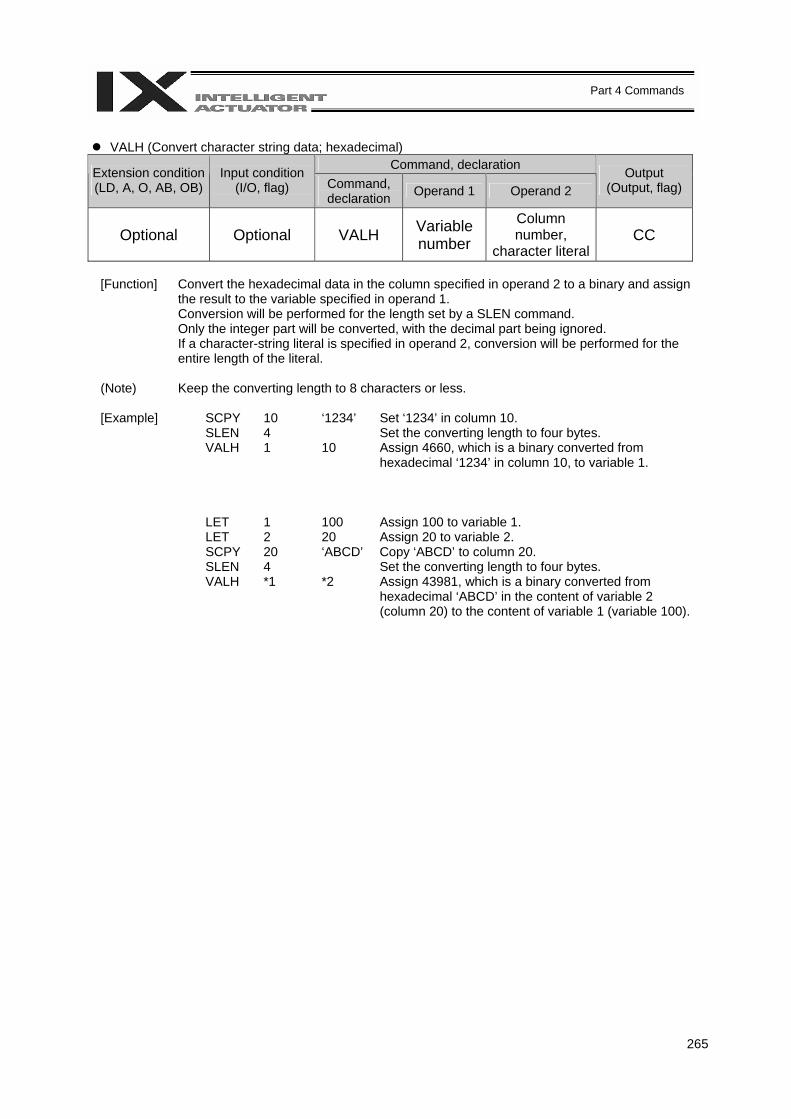
265
Part 4 Commands
VALH (Convert character string data; hexadecimal)
Command, declaration Extension condition (LD, A, O, AB, OB)
Input condition (I/O, flag) Command,
declaration Operand 1 Operand 2 Output
(Output, flag)
Optional Optional VALH Variable number
Column number,
character literal CC
[Function] Convert the hexadecimal data in the column specified in operand 2 to a binary and assign
the result to the variable specified in operand 1. Conversion will be performed for the length set by a SLEN command. Only the integer part will be converted, with the decimal part being ignored. If a character-string literal is specified in operand 2, conversion will be performed for the entire length of the literal.
(Note) Keep the converting length to 8 characters or less. [Example] SCPY 10 ‘1234’ Set ‘1234’ in column 10. SLEN 4 Set the converting length to four bytes. VALH 1 10 Assign 4660, which is a binary converted from
hexadecimal ‘1234’ in column 10, to variable 1. LET 1 100 Assign 100 to variable 1. LET 2 20 Assign 20 to variable 2. SCPY 20 ‘ABCD’ Copy ‘ABCD’ to column 20. SLEN 4 Set the converting length to four bytes. VALH *1 *2 Assign 43981, which is a binary converted from
hexadecimal ‘ABCD’ in the content of variable 2 (column 20) to the content of variable 1 (variable 100).
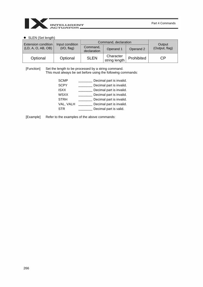
266
Part 4 Commands
SLEN (Set length)
Command, declaration Extension condition (LD, A, O, AB, OB)
Input condition (I/O, flag) Command,
declaration Operand 1 Operand 2 Output
(Output, flag)
Optional Optional SLEN Character string length Prohibited CP
[Function] Set the length to be processed by a string command.
This must always be set before using the following commands:
SCMP Decimal part is invalid. SCPY Decimal part is invalid. ISXX Decimal part is invalid. WSXX Decimal part is invalid. STRH Decimal part is invalid. VAL, VALH Decimal part is invalid. STR Decimal part is valid.
[Example] Refer to the examples of the above commands:
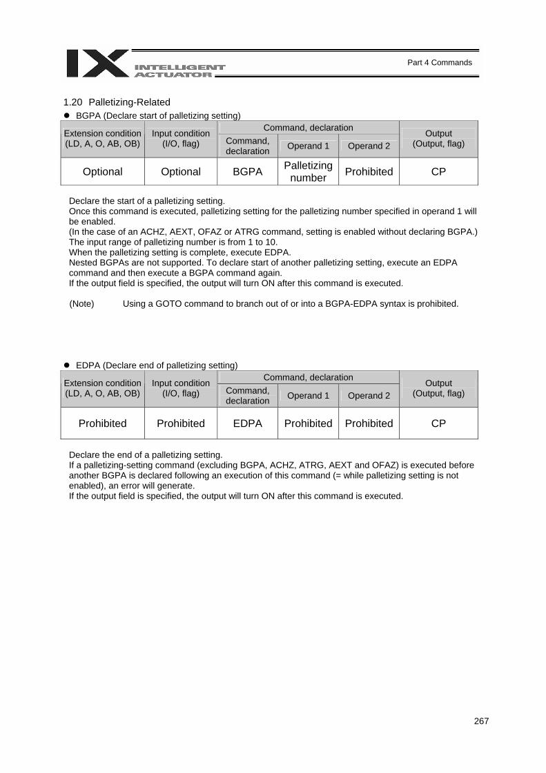
267
Part 4 Commands
1.20 Palletizing-Related
BGPA (Declare start of palletizing setting) Command, declaration Extension condition
(LD, A, O, AB, OB) Input condition
(I/O, flag) Command, declaration Operand 1 Operand 2
Output (Output, flag)
Optional Optional BGPA Palletizing number Prohibited CP
Declare the start of a palletizing setting. Once this command is executed, palletizing setting for the palletizing number specified in operand 1 will be enabled. (In the case of an ACHZ, AEXT, OFAZ or ATRG command, setting is enabled without declaring BGPA.) The input range of palletizing number is from 1 to 10. When the palletizing setting is complete, execute EDPA. Nested BGPAs are not supported. To declare start of another palletizing setting, execute an EDPA command and then execute a BGPA command again. If the output field is specified, the output will turn ON after this command is executed.
(Note) Using a GOTO command to branch out of or into a BGPA-EDPA syntax is prohibited.
EDPA (Declare end of palletizing setting) Command, declaration Extension condition
(LD, A, O, AB, OB) Input condition
(I/O, flag) Command, declaration Operand 1 Operand 2
Output (Output, flag)
Prohibited Prohibited EDPA Prohibited Prohibited CP
Declare the end of a palletizing setting. If a palletizing-setting command (excluding BGPA, ACHZ, ATRG, AEXT and OFAZ) is executed before another BGPA is declared following an execution of this command (= while palletizing setting is not enabled), an error will generate. If the output field is specified, the output will turn ON after this command is executed.
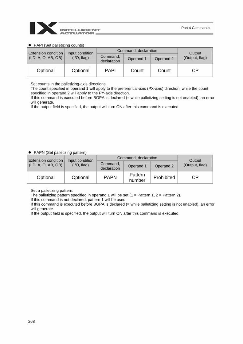
268
Part 4 Commands
PAPI (Set palletizing counts)
Command, declaration Extension condition (LD, A, O, AB, OB)
Input condition (I/O, flag) Command,
declaration Operand 1 Operand 2 Output
(Output, flag)
Optional Optional PAPI Count Count CP
Set counts in the palletizing-axis directions. The count specified in operand 1 will apply to the preferential-axis (PX-axis) direction, while the count specified in operand 2 will apply to the PY-axis direction. If this command is executed before BGPA is declared (= while palletizing setting is not enabled), an error will generate. If the output field is specified, the output will turn ON after this command is executed.
PAPN (Set palletizing pattern) Command, declaration Extension condition
(LD, A, O, AB, OB) Input condition
(I/O, flag) Command, declaration Operand 1 Operand 2
Output (Output, flag)
Optional Optional PAPN Pattern number Prohibited CP
Set a palletizing pattern. The palletizing pattern specified in operand 1 will be set (1 = Pattern 1, 2 = Pattern 2). If this command is not declared, pattern 1 will be used. If this command is executed before BGPA is declared (= while palletizing setting is not enabled), an error will generate. If the output field is specified, the output will turn ON after this command is executed.
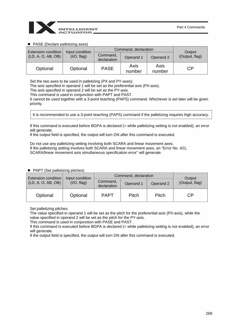
269
Part 4 Commands
PASE (Declare palletizing axes)
Command, declaration Extension condition (LD, A, O, AB, OB)
Input condition (I/O, flag) Command,
declaration Operand 1 Operand 2 Output
(Output, flag)
Optional Optional PASE Axis number
Axis number CP
Set the two axes to be used in palletizing (PX and PY-axes). The axis specified in operand 1 will be set as the preferential axis (PX-axis). The axis specified in operand 2 will be set as the PY-axis. This command is used in conjunction with PAPT and PAST. It cannot be used together with a 3-point teaching (PAPS) command. Whichever is set later will be given priority.
It is recommended to use a 3-point teaching (PAPS) command if the palletizing requires high accuracy.
If this command is executed before BGPA is declared (= while palletizing setting is not enabled), an error will generate. If the output field is specified, the output will turn ON after this command is executed. Do not use any palletizing setting involving both SCARA and linear movement axes. If the palletizing setting involves both SCARA and linear movement axes, an “Error No. 421, SCARA/linear movement axis simultaneous specification error” will generate.
PAPT (Set palletizing pitches) Command, declaration Extension condition
(LD, A, O, AB, OB) Input condition
(I/O, flag) Command, declaration Operand 1 Operand 2
Output (Output, flag)
Optional Optional PAPT Pitch Pitch CP
Set palletizing pitches. The value specified in operand 1 will be set as the pitch for the preferential axis (PX-axis), while the value specified in operand 2 will be set as the pitch for the PY-axis. This command is used in conjunction with PASE and PAST. If this command is executed before BGPA is declared (= while palletizing setting is not enabled), an error will generate. If the output field is specified, the output will turn ON after this command is executed.
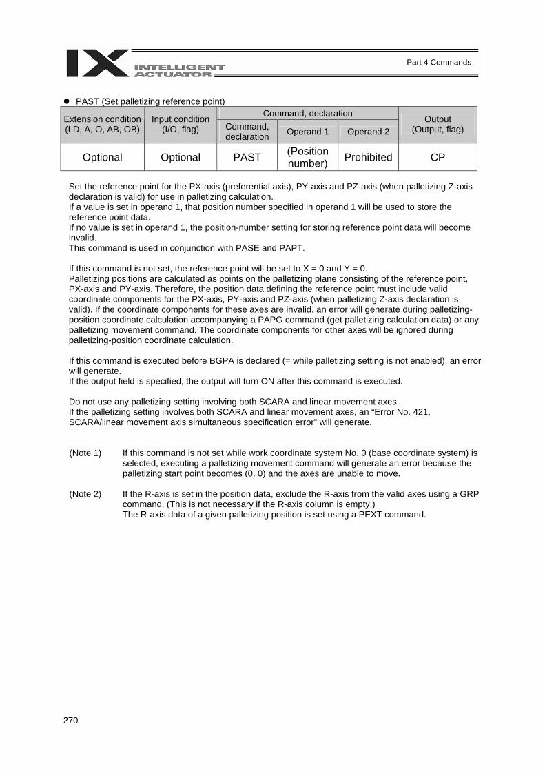
270
Part 4 Commands
PAST (Set palletizing reference point)
Command, declaration Extension condition (LD, A, O, AB, OB)
Input condition (I/O, flag) Command,
declaration Operand 1 Operand 2 Output
(Output, flag)
Optional Optional PAST (Position number) Prohibited CP
Set the reference point for the PX-axis (preferential axis), PY-axis and PZ-axis (when palletizing Z-axis declaration is valid) for use in palletizing calculation. If a value is set in operand 1, that position number specified in operand 1 will be used to store the reference point data. If no value is set in operand 1, the position-number setting for storing reference point data will become invalid. This command is used in conjunction with PASE and PAPT. If this command is not set, the reference point will be set to X = 0 and Y = 0. Palletizing positions are calculated as points on the palletizing plane consisting of the reference point, PX-axis and PY-axis. Therefore, the position data defining the reference point must include valid coordinate components for the PX-axis, PY-axis and PZ-axis (when palletizing Z-axis declaration is valid). If the coordinate components for these axes are invalid, an error will generate during palletizing-position coordinate calculation accompanying a PAPG command (get palletizing calculation data) or any palletizing movement command. The coordinate components for other axes will be ignored during palletizing-position coordinate calculation. If this command is executed before BGPA is declared (= while palletizing setting is not enabled), an error will generate. If the output field is specified, the output will turn ON after this command is executed. Do not use any palletizing setting involving both SCARA and linear movement axes. If the palletizing setting involves both SCARA and linear movement axes, an “Error No. 421, SCARA/linear movement axis simultaneous specification error” will generate.
(Note 1) If this command is not set while work coordinate system No. 0 (base coordinate system) is selected, executing a palletizing movement command will generate an error because the palletizing start point becomes (0, 0) and the axes are unable to move.
(Note 2) If the R-axis is set in the position data, exclude the R-axis from the valid axes using a GRP command. (This is not necessary if the R-axis column is empty.) The R-axis data of a given palletizing position is set using a PEXT command.
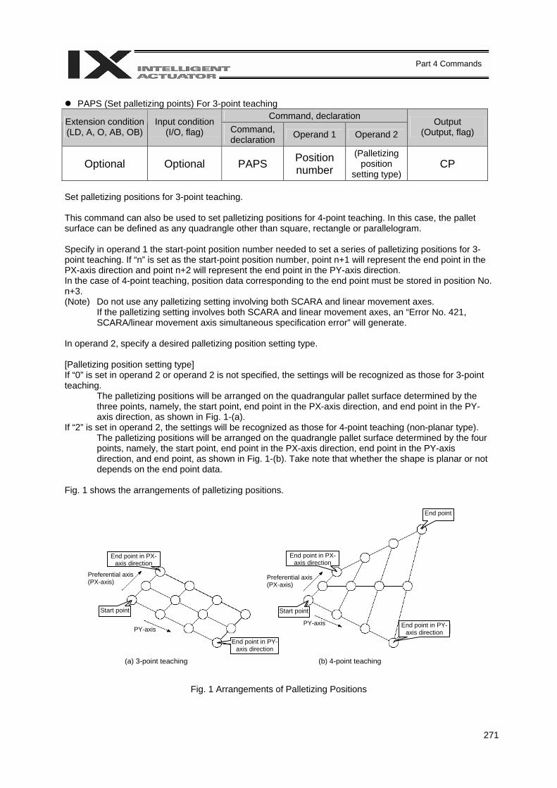
271
Part 4 Commands
PAPS (Set palletizing points) For 3-point teaching
Command, declaration Extension condition (LD, A, O, AB, OB)
Input condition (I/O, flag) Command,
declaration Operand 1 Operand 2 Output
(Output, flag)
Optional Optional PAPS Position number
(Palletizing position
setting type) CP
Set palletizing positions for 3-point teaching. This command can also be used to set palletizing positions for 4-point teaching. In this case, the pallet surface can be defined as any quadrangle other than square, rectangle or parallelogram. Specify in operand 1 the start-point position number needed to set a series of palletizing positions for 3-point teaching. If “n” is set as the start-point position number, point n+1 will represent the end point in the PX-axis direction and point n+2 will represent the end point in the PY-axis direction. In the case of 4-point teaching, position data corresponding to the end point must be stored in position No. n+3. (Note) Do not use any palletizing setting involving both SCARA and linear movement axes. If the palletizing setting involves both SCARA and linear movement axes, an “Error No. 421,
SCARA/linear movement axis simultaneous specification error” will generate. In operand 2, specify a desired palletizing position setting type. [Palletizing position setting type] If “0” is set in operand 2 or operand 2 is not specified, the settings will be recognized as those for 3-point teaching.
The palletizing positions will be arranged on the quadrangular pallet surface determined by the three points, namely, the start point, end point in the PX-axis direction, and end point in the PY-axis direction, as shown in Fig. 1-(a).
If “2” is set in operand 2, the settings will be recognized as those for 4-point teaching (non-planar type). The palletizing positions will be arranged on the quadrangle pallet surface determined by the four
points, namely, the start point, end point in the PX-axis direction, end point in the PY-axis direction, and end point, as shown in Fig. 1-(b). Take note that whether the shape is planar or not depends on the end point data.
Fig. 1 shows the arrangements of palletizing positions.
Fig. 1 Arrangements of Palletizing Positions
End point in PX-axis direction
Preferential axis (PX-axis)
Start point
PY-axis PY-axis
End point in PY-axis direction
(a) 3-point teaching (b) 4-point teaching
End point
End point in PX-axis direction
Start point
End point in PY-axis direction
Preferential axis (PX-axis)

272
Part 4 Commands
• When setting palletizing positions for 4-point teaching where all four points are known to be on a plane
and the settings also require accuracy, it is recommended that non-planar settings be used. If “1” is set in operand 2, the settings will be recognized as those for 4-point teaching (planar type). The plane is determined by the three points, namely, the start point, end point in the PX-axis direction, and end point in the PY-axis direction, as shown in Fig. 2-(a). Move the end point in parallel toward the PZ direction (vertical direction), and the intersection with the aforementioned plane will become the end point of this palletizing movement. Arrange palletizing positions on the quadrangular pallet surface determined by these four points.
Fig. 2-(a)
However, caution must be exercised when the three points excluding the end point meet any of the conditions specified in Table 1, because then the moving direction of the end point will vary. This is when the plane determined by the three points excluding the end point is lying vertical to the ground. In this case, moving the end point in parallel toward the PZ direction (vertical direction) will not find an intersection with the aforementioned plane.
Table 1 Moving Directions of End Point in Planar Specification
Condition Moving direction of end point The point data of the axis i component matches among all three points excluding the end point (refer to Fig. 2-(b)). Move in parallel toward axis i.
The point data other than that of the PZ-axis component matches between the start point and the end point in the PX-axis direction (refer to Fig. 2-(c)). The point data other than that of the PZ-axis component matches between the start point and the end point in the PY-axis direction (refer to Fig. 2-(c)). The point data other than that of the PZ-axis component matches between the end point in the PX-axis direction and the end point in the PY-axis direction (refer to Fig. 2-(c)).
Move in parallel toward one of the two axes other than the PZ-axis, whichever has the smaller axis number.
* i indicates the axis number for either of the two axes other than the PZ-axis.
End point in PX-axis
direction
Start point
End point in PY-axis direction
End pointAxis i+2
Axis i+1
Axis i
Move in parallel toward PZ-axis direction
In a planar specification, the palletizing positions are arranged on the plane determined by the three points excluding the end point.
End point in planar specification

273
Part 4 Commands
Fig. 2-(b) When the point data of the axis i component matches among all three points excluding the end point
Fig. 2-(c) When the point data of the two points other than that of the PZ-axis component matches among the three points excluding the end point (= in the above figure, when the point data other than that of the PZ-axis component matches between the start point and the end point in the PY-axis direction)
• If the valid axis pattern of the 3-point teaching or 4-point teaching data does not match, an error “CB0,
Mismatched valid axes and palletizing 3-point teaching data” will generate. Take note that if this command is executed after specifying the axes to be used with a GRP command, only the specified axes will be used for palletizing position data, among all valid axes with point data. Executing GRP again thereafter in other settings will not have any effect.
• If a PZ-axis has been declared, the number of valid axes excluding the PZ-axis must be two. If a PZ-
axis has not been declared yet, the number of valid axes excluding the PZ-axis must be two or three. If the number of valid axes is not sufficient, an error “CAE, Insufficient valid axes for palletizing 3-point teaching data” will generate. If there are too many valid axes, on the other hand, an error, “CAF, Excessive valid axes for palletizing 3-point teaching data” will generate. When a PZ-axis has not yet been declared in a planar specification, keep the number of valid axes to two. If the number of valid axes is other than two in this condition, an error, “CB4, Arch-motion Z-axis non-declaration error” will generate.
End point in PX-axis direction
Start point
End point in PY-axis direction
End pointAxis i+2
Axis i+1
Axis i
Move the end point in parallel toward axis i, and the palletizing positions will be arranged on the plane determined by the three points excluding the end point.
Move in parallel toward axis i
Start point
Axis i+2
Axis i
Move in parallel toward axis i
Axis i+1
If the PZ-axis component is axis i+2, the remaining two axes are axis i and axis i+1, of which axis i has the smallest axis number. Therefore, move the end point in parallel toward axis i, and the palletizing positions will be arranged on the plane determined by the three points excluding the end point.
End point in planar specification
End point in PX-axis direction
End point in PY-axis direction
End point
End point in planar specification

274
Part 4 Commands
• This command cannot be used with PASE (set palletizing axes). Whichever is set later will be given
priority. (A single PAPS command can substitute PASE, PAPT and PAST.) • If this command is executed before BGPA is declared (= while palletizing setting is not enabled), an
error “CB5, BGPA non-declaration error during palletizing setting” will generate. • If the output field is specified, the output will turn ON after this command is executed.
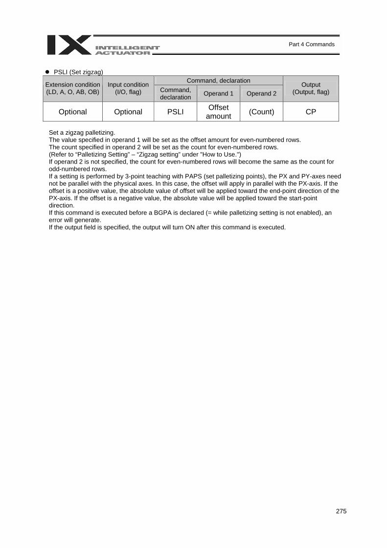
275
Part 4 Commands
PSLI (Set zigzag)
Command, declaration Extension condition (LD, A, O, AB, OB)
Input condition (I/O, flag) Command,
declaration Operand 1 Operand 2 Output
(Output, flag)
Optional Optional PSLI Offset amount (Count) CP
Set a zigzag palletizing. The value specified in operand 1 will be set as the offset amount for even-numbered rows. The count specified in operand 2 will be set as the count for even-numbered rows. (Refer to “Palletizing Setting” – “Zigzag setting” under "How to Use.") If operand 2 is not specified, the count for even-numbered rows will become the same as the count for odd-numbered rows. If a setting is performed by 3-point teaching with PAPS (set palletizing points), the PX and PY-axes need not be parallel with the physical axes. In this case, the offset will apply in parallel with the PX-axis. If the offset is a positive value, the absolute value of offset will be applied toward the end-point direction of the PX-axis. If the offset is a negative value, the absolute value will be applied toward the start-point direction. If this command is executed before a BGPA is declared (= while palletizing setting is not enabled), an error will generate. If the output field is specified, the output will turn ON after this command is executed.
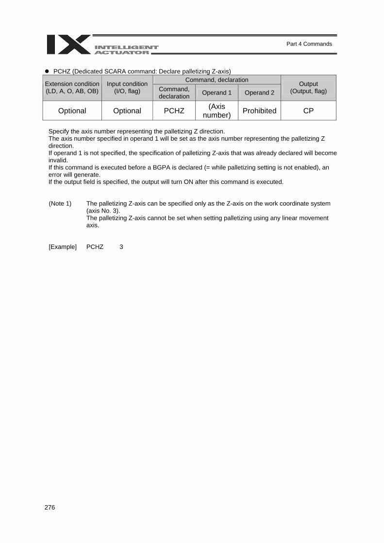
276
Part 4 Commands
PCHZ (Dedicated SCARA command: Declare palletizing Z-axis)
Command, declaration Extension condition (LD, A, O, AB, OB)
Input condition (I/O, flag) Command,
declaration Operand 1 Operand 2 Output
(Output, flag)
Optional Optional PCHZ (Axis number) Prohibited CP
Specify the axis number representing the palletizing Z direction. The axis number specified in operand 1 will be set as the axis number representing the palletizing Z direction. If operand 1 is not specified, the specification of palletizing Z-axis that was already declared will become invalid. If this command is executed before a BGPA is declared (= while palletizing setting is not enabled), an error will generate. If the output field is specified, the output will turn ON after this command is executed. (Note 1) The palletizing Z-axis can be specified only as the Z-axis on the work coordinate system
(axis No. 3). The palletizing Z-axis cannot be set when setting palletizing using any linear movement axis.
[Example] PCHZ 3
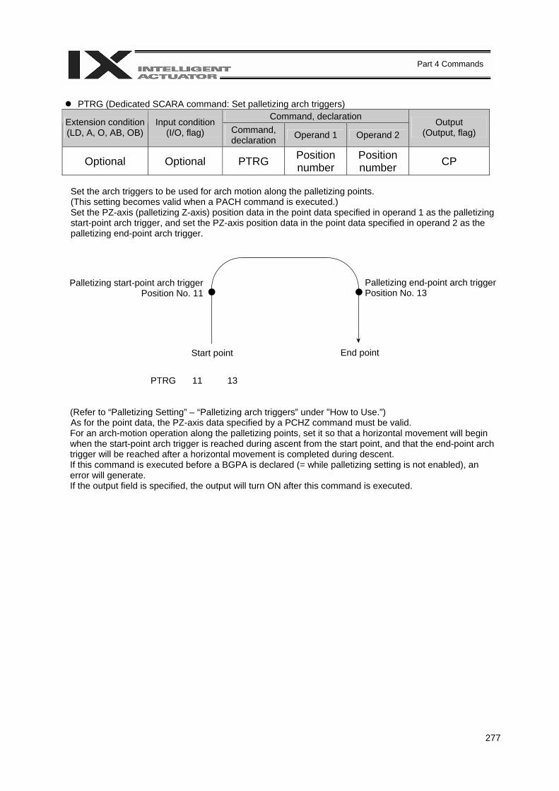
277
Part 4 Commands
PTRG (Dedicated SCARA command: Set palletizing arch triggers)
Command, declaration Extension condition (LD, A, O, AB, OB)
Input condition (I/O, flag) Command,
declaration Operand 1 Operand 2 Output
(Output, flag)
Optional Optional PTRG Position number
Position number CP
Set the arch triggers to be used for arch motion along the palletizing points. (This setting becomes valid when a PACH command is executed.) Set the PZ-axis (palletizing Z-axis) position data in the point data specified in operand 1 as the palletizing start-point arch trigger, and set the PZ-axis position data in the point data specified in operand 2 as the palletizing end-point arch trigger.
PTRG 11 13
(Refer to “Palletizing Setting” – “Palletizing arch triggers” under "How to Use.") As for the point data, the PZ-axis data specified by a PCHZ command must be valid. For an arch-motion operation along the palletizing points, set it so that a horizontal movement will begin when the start-point arch trigger is reached during ascent from the start point, and that the end-point arch trigger will be reached after a horizontal movement is completed during descent. If this command is executed before a BGPA is declared (= while palletizing setting is not enabled), an error will generate. If the output field is specified, the output will turn ON after this command is executed.
Palletizing start-point arch trigger Position No. 11
Palletizing end-point arch trigger Position No. 13
Start point End point
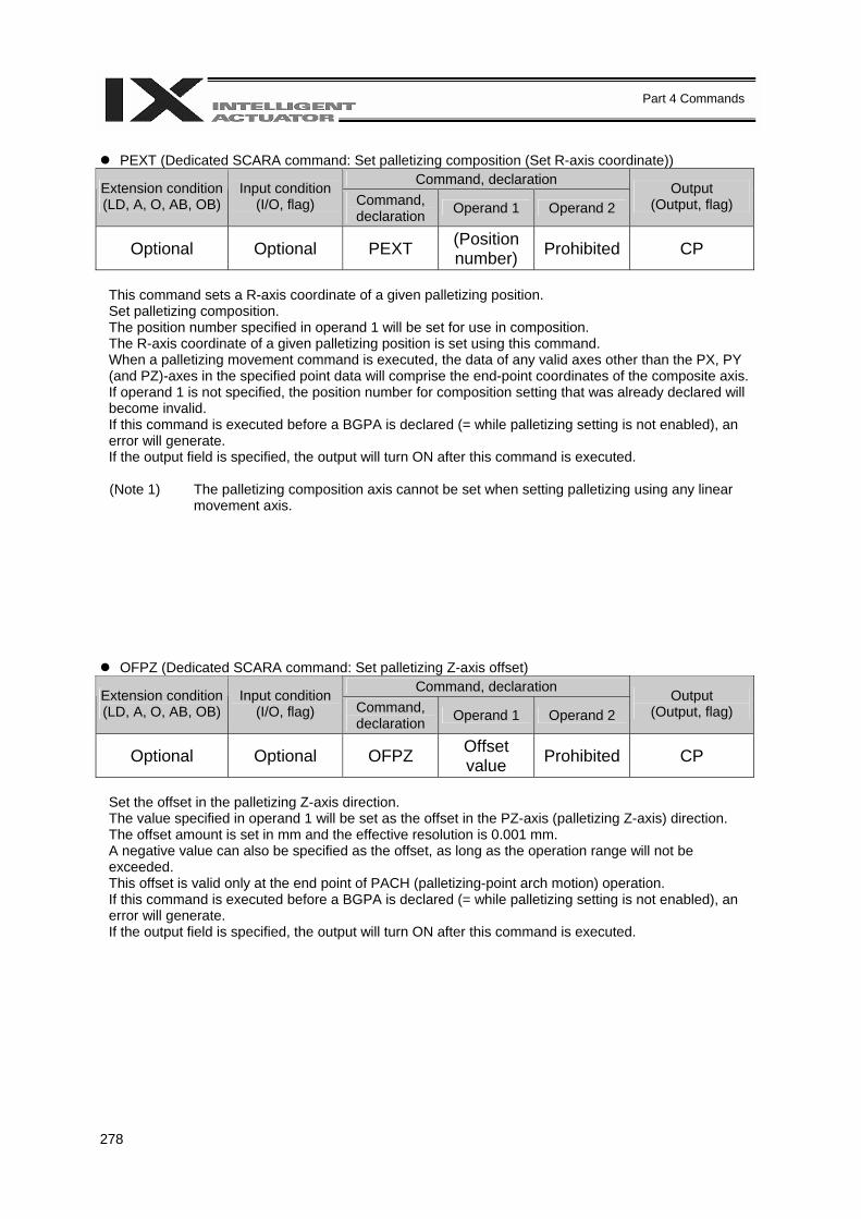
278
Part 4 Commands
PEXT (Dedicated SCARA command: Set palletizing composition (Set R-axis coordinate))
Command, declaration Extension condition (LD, A, O, AB, OB)
Input condition (I/O, flag) Command,
declaration Operand 1 Operand 2 Output
(Output, flag)
Optional Optional PEXT (Position number) Prohibited CP
This command sets a R-axis coordinate of a given palletizing position. Set palletizing composition. The position number specified in operand 1 will be set for use in composition. The R-axis coordinate of a given palletizing position is set using this command. When a palletizing movement command is executed, the data of any valid axes other than the PX, PY (and PZ)-axes in the specified point data will comprise the end-point coordinates of the composite axis. If operand 1 is not specified, the position number for composition setting that was already declared will become invalid. If this command is executed before a BGPA is declared (= while palletizing setting is not enabled), an error will generate. If the output field is specified, the output will turn ON after this command is executed. (Note 1) The palletizing composition axis cannot be set when setting palletizing using any linear
movement axis.
OFPZ (Dedicated SCARA command: Set palletizing Z-axis offset) Command, declaration Extension condition
(LD, A, O, AB, OB) Input condition
(I/O, flag) Command, declaration Operand 1 Operand 2
Output (Output, flag)
Optional Optional OFPZ Offset value Prohibited CP
Set the offset in the palletizing Z-axis direction. The value specified in operand 1 will be set as the offset in the PZ-axis (palletizing Z-axis) direction. The offset amount is set in mm and the effective resolution is 0.001 mm. A negative value can also be specified as the offset, as long as the operation range will not be exceeded. This offset is valid only at the end point of PACH (palletizing-point arch motion) operation. If this command is executed before a BGPA is declared (= while palletizing setting is not enabled), an error will generate. If the output field is specified, the output will turn ON after this command is executed.
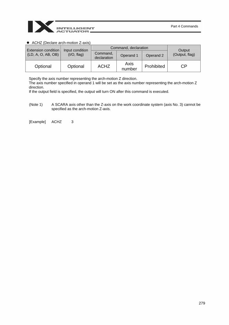
279
Part 4 Commands
ACHZ (Declare arch-motion Z-axis)
Command, declaration Extension condition (LD, A, O, AB, OB)
Input condition (I/O, flag) Command,
declaration Operand 1 Operand 2 Output
(Output, flag)
Optional Optional ACHZ Axis number Prohibited CP
Specify the axis number representing the arch-motion Z direction. The axis number specified in operand 1 will be set as the axis number representing the arch-motion Z direction. If the output field is specified, the output will turn ON after this command is executed.
(Note 1) A SCARA axis other than the Z-axis on the work coordinate system (axis No. 3) cannot be specified as the arch-motion Z-axis.
[Example] ACHZ 3
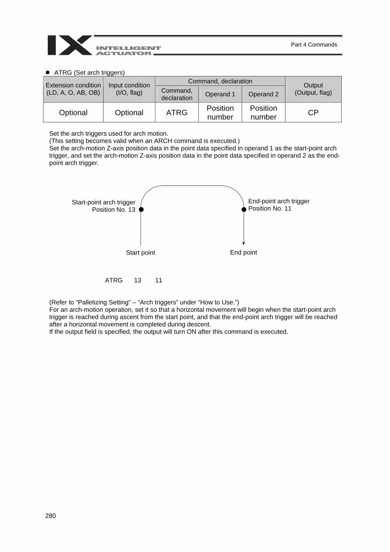
280
Part 4 Commands
ATRG (Set arch triggers)
Command, declaration Extension condition (LD, A, O, AB, OB)
Input condition (I/O, flag) Command,
declaration Operand 1 Operand 2 Output
(Output, flag)
Optional Optional ATRG Position number
Position number CP
Set the arch triggers used for arch motion. (This setting becomes valid when an ARCH command is executed.) Set the arch-motion Z-axis position data in the point data specified in operand 1 as the start-point arch trigger, and set the arch-motion Z-axis position data in the point data specified in operand 2 as the end-point arch trigger.
ATRG 13 11
(Refer to “Palletizing Setting” – “Arch triggers” under “How to Use.”) For an arch-motion operation, set it so that a horizontal movement will begin when the start-point arch trigger is reached during ascent from the start point, and that the end-point arch trigger will be reached after a horizontal movement is completed during descent. If the output field is specified, the output will turn ON after this command is executed.
Start-point arch trigger Position No. 13
End-point arch trigger Position No. 11
Start point End point

281
Part 4 Commands
AEXT (Dedicated SCARA command: Set arch-motion composition)
Command, declaration Extension condition (LD, A, O, AB, OB)
Input condition (I/O, flag) Command,
declaration Operand 1 Operand 2 Output
(Output, flag)
Optional Optional AEXT (Position number) Prohibited CP
Set arch-motion composition. The position number specified in operand 1 will be set for use in composition. When an arch motion is executed, the data of valid axes in the point data specified in this command, except for the data of valid axes in the arch-motion end-point data as well as the arch-motion Z-axis data, will comprise the end-point coordinates of the composite axis. If operand 1 is not specified, the position number for composition setting that was already declared will become invalid. If the output field is specified, the output will turn ON after this command is executed. (Note 1) Linear movement axes cannot be set as the axes for arch-motion composition.
OFAZ (Set arch-motion Z-axis offset) Command, declaration Extension condition
(LD, A, O, AB, OB) Input condition
(I/O, flag) Command, declaration Operand 1 Operand 2
Output (Output, flag)
Optional Optional OFAZ Offset value Prohibited CP
Set the offset in the arch-motion Z-axis direction. The value specified in operand 1 will be set as the offset in the arch-motion Z-axis direction. The offset amount is set in mm and the effective resolution is 0.001 mm. A negative value can also be specified as the offset, as long as the operation range will not be exceeded. This offset is valid only at the end point of ARCH (arch motion) operation. If the output field is specified, the output will turn ON after this command is executed.
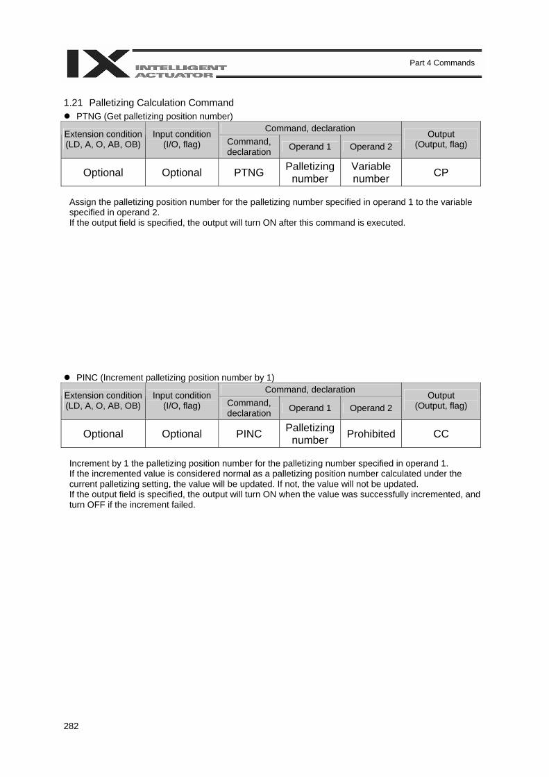
282
Part 4 Commands
1.21 Palletizing Calculation Command
PTNG (Get palletizing position number) Command, declaration Extension condition
(LD, A, O, AB, OB) Input condition
(I/O, flag) Command, declaration Operand 1 Operand 2
Output (Output, flag)
Optional Optional PTNG Palletizing number
Variable number CP
Assign the palletizing position number for the palletizing number specified in operand 1 to the variable specified in operand 2. If the output field is specified, the output will turn ON after this command is executed.
PINC (Increment palletizing position number by 1) Command, declaration Extension condition
(LD, A, O, AB, OB) Input condition
(I/O, flag) Command, declaration Operand 1 Operand 2
Output (Output, flag)
Optional Optional PINC Palletizing number Prohibited CC
Increment by 1 the palletizing position number for the palletizing number specified in operand 1. If the incremented value is considered normal as a palletizing position number calculated under the current palletizing setting, the value will be updated. If not, the value will not be updated. If the output field is specified, the output will turn ON when the value was successfully incremented, and turn OFF if the increment failed.
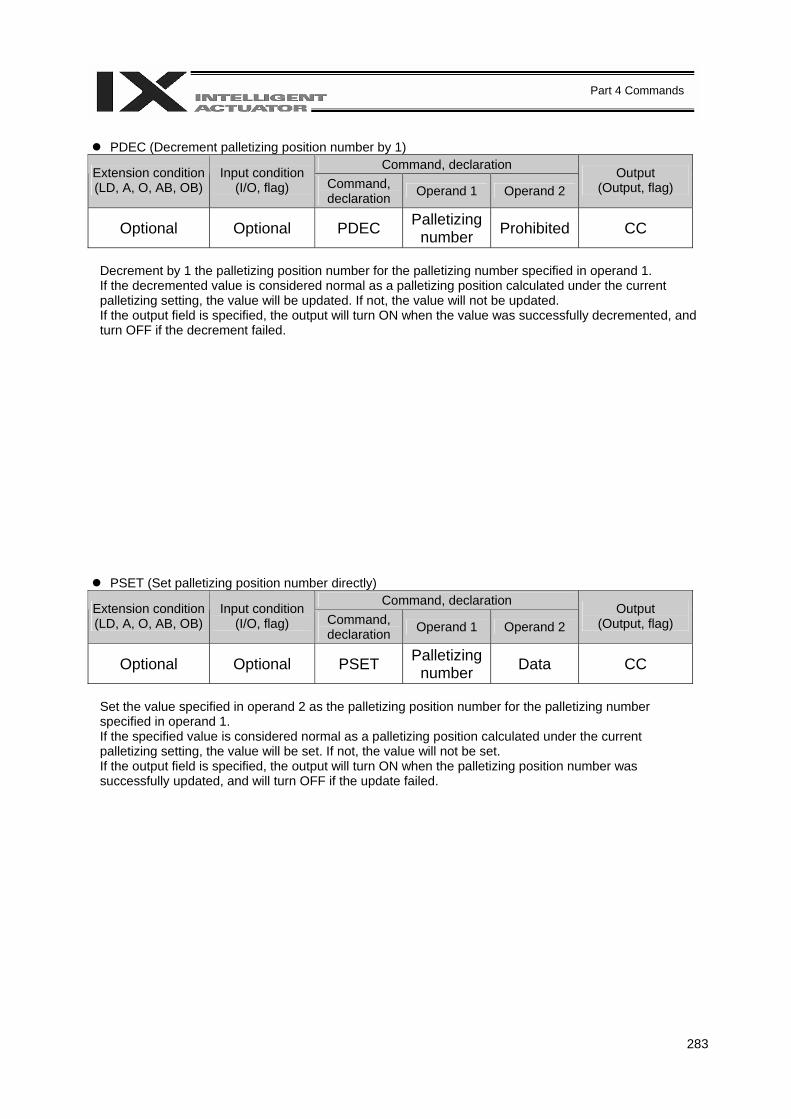
283
Part 4 Commands
PDEC (Decrement palletizing position number by 1)
Command, declaration Extension condition (LD, A, O, AB, OB)
Input condition (I/O, flag) Command,
declaration Operand 1 Operand 2 Output
(Output, flag)
Optional Optional PDEC Palletizing number Prohibited CC
Decrement by 1 the palletizing position number for the palletizing number specified in operand 1. If the decremented value is considered normal as a palletizing position calculated under the current palletizing setting, the value will be updated. If not, the value will not be updated. If the output field is specified, the output will turn ON when the value was successfully decremented, and turn OFF if the decrement failed.
PSET (Set palletizing position number directly) Command, declaration Extension condition
(LD, A, O, AB, OB) Input condition
(I/O, flag) Command, declaration Operand 1 Operand 2
Output (Output, flag)
Optional Optional PSET Palletizing number Data CC
Set the value specified in operand 2 as the palletizing position number for the palletizing number specified in operand 1. If the specified value is considered normal as a palletizing position calculated under the current palletizing setting, the value will be set. If not, the value will not be set. If the output field is specified, the output will turn ON when the palletizing position number was successfully updated, and will turn OFF if the update failed.
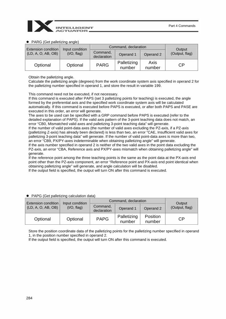
284
Part 4 Commands
PARG (Get palletizing angle)
Command, declaration Extension condition (LD, A, O, AB, OB)
Input condition (I/O, flag) Command,
declaration Operand 1 Operand 2 Output
(Output, flag)
Optional Optional PARG Palletizing number
Axis number CP
Obtain the palletizing angle. Calculate the palletizing angle (degrees) from the work coordinate system axis specified in operand 2 for the palletizing number specified in operand 1, and store the result in variable 199. This command need not be executed, if not necessary. If this command is executed after PAPS (set 3 palletizing points for teaching) is executed, the angle formed by the preferential axis and the specified work coordinate system axis will be calculated automatically. If this command is executed before PAPS is executed, or after both PAPS and PASE are executed in this order, an error will generate. The axes to be used can be specified with a GRP command before PAPS is executed (refer to the detailed explanation of PAPS). If the valid axis pattern of the 3-point teaching data does not match, an error “CB0, Mismatched valid axes and palletizing 3-point teaching data” will generate. If the number of valid point-data axes (the number of valid axes excluding the PZ-axis, if a PZ-axis (palletizing Z-axis) has already been declared) is less than two, an error “CAE, Insufficient valid axes for palletizing 3-point teaching data” will generate. If the number of valid point-data axes is more than two, an error “CB9, PX/PY-axes indeterminable when obtaining palletizing angle” will generate. If the axis number specified in operand 2 is neither of the two valid axes in the point data excluding the PZ-axis, an error “CBA, Reference axis and PX/PY-axes mismatch when obtaining palletizing angle” will generate. If the reference point among the three teaching points is the same as the point data at the PX-axis end point other than the PZ-axis component, an error “Reference point and PX-axis end point identical when obtaining palletizing angle” will generate, and angle calculation will be disabled. If the output field is specified, the output will turn ON after this command is executed.
PAPG (Get palletizing calculation data) Command, declaration Extension condition
(LD, A, O, AB, OB) Input condition
(I/O, flag) Command, declaration Operand 1 Operand 2
Output (Output, flag)
Optional Optional PAPG Palletizing number
Position number CP
Store the position coordinate data of the palletizing points for the palletizing number specified in operand 1, in the position number specified in operand 2. If the output field is specified, the output will turn ON after this command is executed.
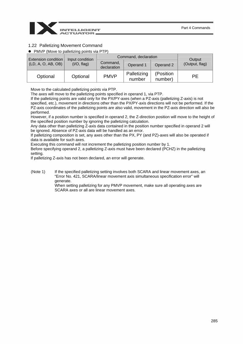
285
Part 4 Commands
1.22 Palletizing Movement Command
PMVP (Move to palletizing points via PTP) Command, declaration Extension condition
(LD, A, O, AB, OB) Input condition
(I/O, flag) Command, declaration Operand 1 Operand 2
Output (Output, flag)
Optional Optional PMVP Palletizing number
(Position number) PE
Move to the calculated palletizing points via PTP. The axes will move to the palletizing points specified in operand 1, via PTP. If the palletizing points are valid only for the PX/PY-axes (when a PZ-axis (palletizing Z-axis) is not specified, etc.), movement in directions other than the PX/PY-axis directions will not be performed. If the PZ-axis coordinates of the palletizing points are also valid, movement in the PZ-axis direction will also be performed. However, if a position number is specified in operand 2, the Z-direction position will move to the height of the specified position number by ignoring the palletizing calculation. Any data other than palletizing Z-axis data contained in the position number specified in operand 2 will be ignored. Absence of PZ-axis data will be handled as an error. If palletizing composition is set, any axes other than the PX, PY (and PZ)-axes will also be operated if data is available for such axes. Executing this command will not increment the palletizing position number by 1. Before specifying operand 2, a palletizing Z-axis must have been declared (PCHZ) in the palletizing setting. If palletizing Z-axis has not been declared, an error will generate. (Note 1) If the specified palletizing setting involves both SCARA and linear movement axes, an
“Error No. 421, SCARA/linear movement axis simultaneous specification error” will generate. When setting palletizing for any PMVP movement, make sure all operating axes are SCARA axes or all are linear movement axes.
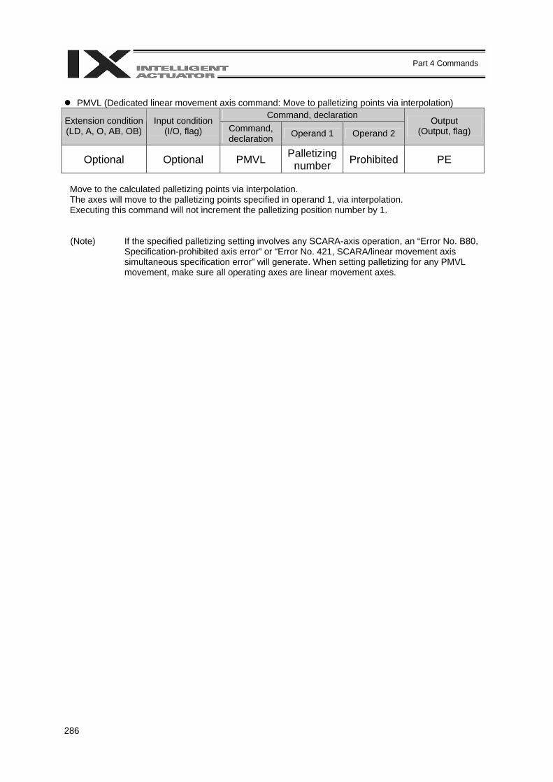
286
Part 4 Commands
PMVL (Dedicated linear movement axis command: Move to palletizing points via interpolation)
Command, declaration Extension condition (LD, A, O, AB, OB)
Input condition (I/O, flag) Command,
declaration Operand 1 Operand 2 Output
(Output, flag)
Optional Optional PMVL Palletizing number Prohibited PE
Move to the calculated palletizing points via interpolation. The axes will move to the palletizing points specified in operand 1, via interpolation. Executing this command will not increment the palletizing position number by 1. (Note) If the specified palletizing setting involves any SCARA-axis operation, an “Error No. B80,
Specification-prohibited axis error” or “Error No. 421, SCARA/linear movement axis simultaneous specification error” will generate. When setting palletizing for any PMVL movement, make sure all operating axes are linear movement axes.
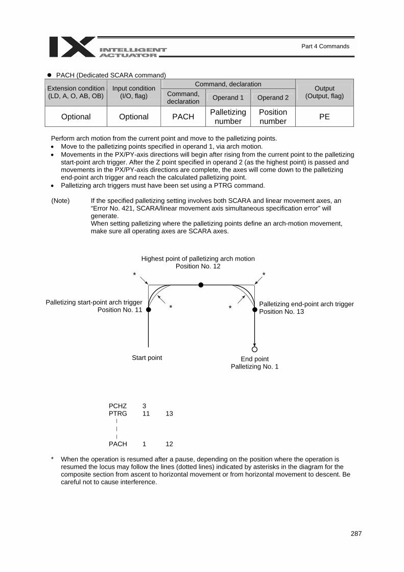
287
Part 4 Commands
PACH (Dedicated SCARA command)
Command, declaration Extension condition (LD, A, O, AB, OB)
Input condition (I/O, flag) Command,
declaration Operand 1 Operand 2 Output
(Output, flag)
Optional Optional PACH Palletizing number
Position number PE
Perform arch motion from the current point and move to the palletizing points. • Move to the palletizing points specified in operand 1, via arch motion. • Movements in the PX/PY-axis directions will begin after rising from the current point to the palletizing
start-point arch trigger. After the Z point specified in operand 2 (as the highest point) is passed and movements in the PX/PY-axis directions are complete, the axes will come down to the palletizing end-point arch trigger and reach the calculated palletizing point.
• Palletizing arch triggers must have been set using a PTRG command. (Note) If the specified palletizing setting involves both SCARA and linear movement axes, an
“Error No. 421, SCARA/linear movement axis simultaneous specification error” will generate. When setting palletizing where the palletizing points define an arch-motion movement, make sure all operating axes are SCARA axes.
PCHZ 3 PTRG 11 13
PACH 1 12
* When the operation is resumed after a pause, depending on the position where the operation is resumed the locus may follow the lines (dotted lines) indicated by asterisks in the diagram for the composite section from ascent to horizontal movement or from horizontal movement to descent. Be careful not to cause interference.
Highest point of palletizing arch motion Position No. 12
* *
* *
Start point End point Palletizing No. 1
Palletizing start-point arch trigger Position No. 11
Palletizing end-point arch trigger Position No. 13
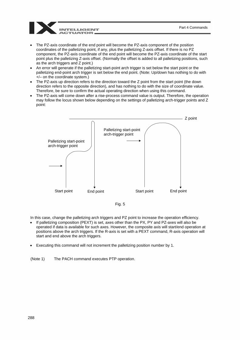
288
Part 4 Commands
• The PZ-axis coordinate of the end point will become the PZ-axis component of the position
coordinates of the palletizing point, if any, plus the palletizing Z-axis offset. If there is no PZ component, the PZ-axis coordinate of the end point will become the PZ-axis coordinate of the start point plus the palletizing Z-axis offset. (Normally the offset is added to all palletizing positions, such as the arch triggers and Z point.)
• An error will generate if the palletizing start-point arch trigger is set below the start point or the palletizing end-point arch trigger is set below the end point. (Note: Up/down has nothing to do with +/– on the coordinate system.)
• The PZ-axis up direction refers to the direction toward the Z point from the start point (the down direction refers to the opposite direction), and has nothing to do with the size of coordinate value. Therefore, be sure to confirm the actual operating direction when using this command.
• The PZ-axis will come down after a rise-process command value is output. Therefore, the operation may follow the locus shown below depending on the settings of palletizing arch-trigger points and Z point:
Fig. 5
In this case, change the palletizing arch triggers and PZ point to increase the operation efficiency. • If palletizing composition (PEXT) is set, axes other than the PX, PY and PZ-axes will also be
operated if data is available for such axes. However, the composite axis will start/end operation at positions above the arch triggers. If the R-axis is set with a PEXT command, R-axis operation will start and end above the arch triggers.
• Executing this command will not increment the palletizing position number by 1. (Note 1) The PACH command executes PTP operation.
Z point
Palletizing start-point arch-trigger point
Palletizing start-point arch-trigger point
Start point End point Start point End point
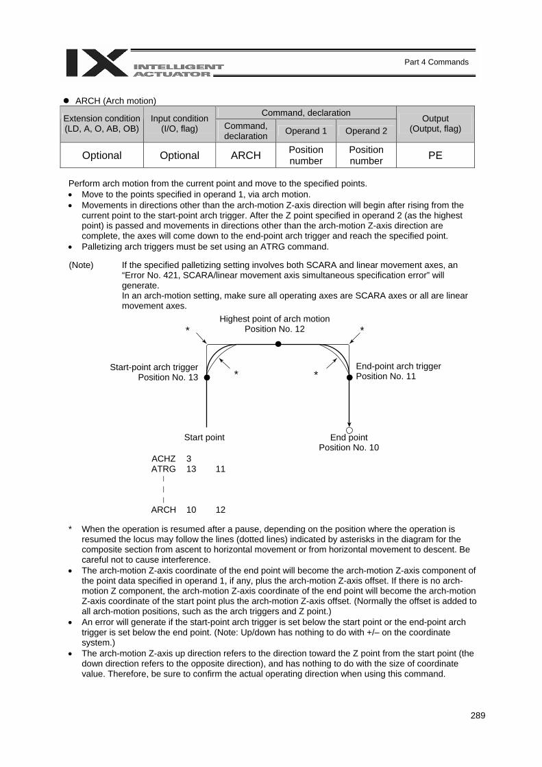
289
Part 4 Commands
ARCH (Arch motion)
Command, declaration Extension condition (LD, A, O, AB, OB)
Input condition (I/O, flag) Command,
declaration Operand 1 Operand 2 Output
(Output, flag)
Optional Optional ARCH Position number
Position number PE
Perform arch motion from the current point and move to the specified points. • Move to the points specified in operand 1, via arch motion. • Movements in directions other than the arch-motion Z-axis direction will begin after rising from the
current point to the start-point arch trigger. After the Z point specified in operand 2 (as the highest point) is passed and movements in directions other than the arch-motion Z-axis direction are complete, the axes will come down to the end-point arch trigger and reach the specified point.
• Palletizing arch triggers must be set using an ATRG command.
(Note) If the specified palletizing setting involves both SCARA and linear movement axes, an “Error No. 421, SCARA/linear movement axis simultaneous specification error” will generate. In an arch-motion setting, make sure all operating axes are SCARA axes or all are linear movement axes.
ACHZ 3 ATRG 13 11 ARCH 10 12
* When the operation is resumed after a pause, depending on the position where the operation is
resumed the locus may follow the lines (dotted lines) indicated by asterisks in the diagram for the composite section from ascent to horizontal movement or from horizontal movement to descent. Be careful not to cause interference.
• The arch-motion Z-axis coordinate of the end point will become the arch-motion Z-axis component of the point data specified in operand 1, if any, plus the arch-motion Z-axis offset. If there is no arch-motion Z component, the arch-motion Z-axis coordinate of the end point will become the arch-motion Z-axis coordinate of the start point plus the arch-motion Z-axis offset. (Normally the offset is added to all arch-motion positions, such as the arch triggers and Z point.)
• An error will generate if the start-point arch trigger is set below the start point or the end-point arch trigger is set below the end point. (Note: Up/down has nothing to do with +/– on the coordinate system.)
• The arch-motion Z-axis up direction refers to the direction toward the Z point from the start point (the down direction refers to the opposite direction), and has nothing to do with the size of coordinate value. Therefore, be sure to confirm the actual operating direction when using this command.
Highest point of arch motion Position No. 12 * *
* * Start-point arch trigger
Position No. 13 End-point arch trigger Position No. 11
Start point End point Position No. 10
290
Part 4 Commands
• The arch-motion Z-axis will come down after a rise-process command value is output. Therefore, the
operation may follow the locus in Fig. 5 given in the aforementioned explanation of PACH command, depending on the settings of arch-trigger points and Z point. In this case, change the arch triggers and Z point to increase the operation efficiency.
• As for the arch-trigger end-point data, if there is any valid axis data other than the data of the arch-
motion Z-axis, then operation will be started/ended for the applicable axes in the same manner—but above the arch triggers.
• If R-axis data is included in the end-point data, R-axis operation will start and end above the arch
triggers. • If arch-trigger composition is set, any valid axes other than those set in the end-point data or the
arch-motion Z-axis will also be operated as long as data is available for such axes. In this case, operation of the applicable axes will also be started/ended above the arch triggers.
(Note 1) The ARCH command executes PTP operation.
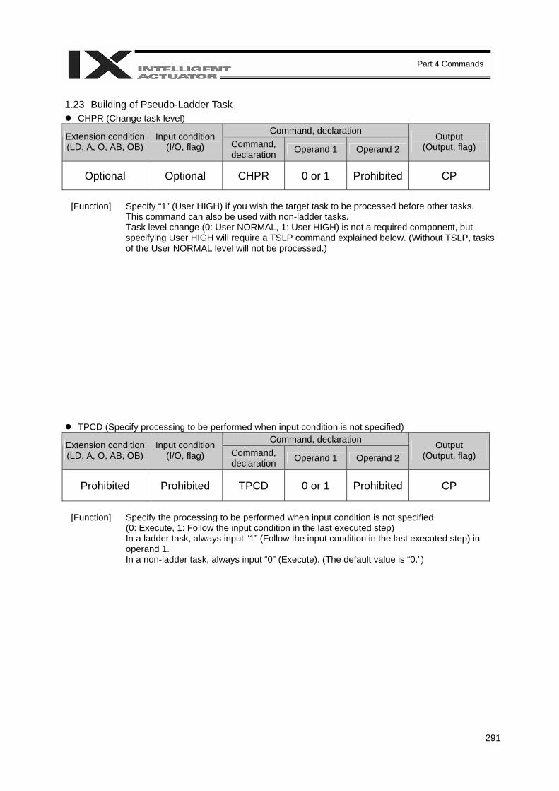
291
Part 4 Commands
1.23 Building of Pseudo-Ladder Task
CHPR (Change task level) Command, declaration Extension condition
(LD, A, O, AB, OB) Input condition
(I/O, flag) Command, declaration Operand 1 Operand 2
Output (Output, flag)
Optional Optional CHPR 0 or 1 Prohibited CP
[Function] Specify “1” (User HIGH) if you wish the target task to be processed before other tasks.
This command can also be used with non-ladder tasks. Task level change (0: User NORMAL, 1: User HIGH) is not a required component, but specifying User HIGH will require a TSLP command explained below. (Without TSLP, tasks of the User NORMAL level will not be processed.)
TPCD (Specify processing to be performed when input condition is not specified) Command, declaration Extension condition
(LD, A, O, AB, OB) Input condition
(I/O, flag) Command, declaration Operand 1 Operand 2
Output (Output, flag)
Prohibited Prohibited TPCD 0 or 1 Prohibited CP
[Function] Specify the processing to be performed when input condition is not specified.
(0: Execute, 1: Follow the input condition in the last executed step) In a ladder task, always input “1” (Follow the input condition in the last executed step) in operand 1. In a non-ladder task, always input “0” (Execute). (The default value is “0.”)
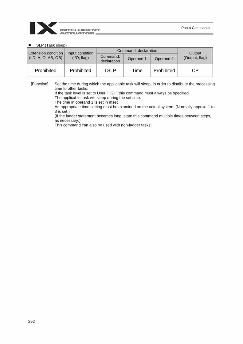
292
Part 4 Commands
TSLP (Task sleep)
Command, declaration Extension condition (LD, A, O, AB, OB)
Input condition (I/O, flag) Command,
declaration Operand 1 Operand 2 Output
(Output, flag)
Prohibited Prohibited TSLP Time Prohibited CP
[Function] Set the time during which the applicable task will sleep, in order to distribute the processing
time to other tasks. If the task level is set to User HIGH, this command must always be specified. The applicable task will sleep during the set time. The time in operand 1 is set in msec. An appropriate time setting must be examined on the actual system. (Normally approx. 1 to 3 is set.) (If the ladder statement becomes long, state this command multiple times between steps, as necessary.) This command can also be used with non-ladder tasks.
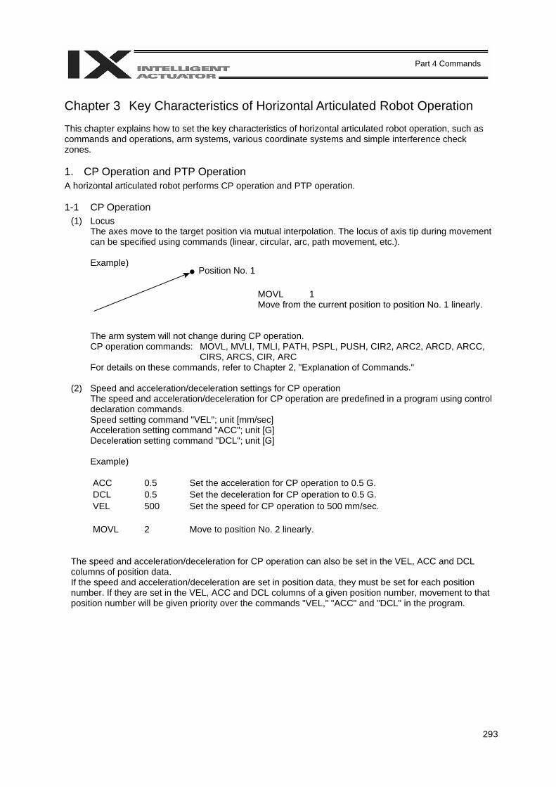
293
Part 4 Commands
Chapter 3 Key Characteristics of Horizontal Articulated Robot Operation This chapter explains how to set the key characteristics of horizontal articulated robot operation, such as commands and operations, arm systems, various coordinate systems and simple interference check zones. 1. CP Operation and PTP Operation A horizontal articulated robot performs CP operation and PTP operation. 1-1 CP Operation
(1) Locus The axes move to the target position via mutual interpolation. The locus of axis tip during movement can be specified using commands (linear, circular, arc, path movement, etc.). Example)
MOVL 1 Move from the current position to position No. 1 linearly.
The arm system will not change during CP operation. CP operation commands: MOVL, MVLI, TMLI, PATH, PSPL, PUSH, CIR2, ARC2, ARCD, ARCC,
CIRS, ARCS, CIR, ARC For details on these commands, refer to Chapter 2, "Explanation of Commands."
(2) Speed and acceleration/deceleration settings for CP operation
The speed and acceleration/deceleration for CP operation are predefined in a program using control declaration commands. Speed setting command "VEL"; unit [mm/sec] Acceleration setting command "ACC"; unit [G] Deceleration setting command "DCL"; unit [G]
Example)
ACC 0.5 Set the acceleration for CP operation to 0.5 G. DCL 0.5 Set the deceleration for CP operation to 0.5 G. VEL 500 Set the speed for CP operation to 500 mm/sec. MOVL 2 Move to position No. 2 linearly.
The speed and acceleration/deceleration for CP operation can also be set in the VEL, ACC and DCL columns of position data. If the speed and acceleration/deceleration are set in position data, they must be set for each position number. If they are set in the VEL, ACC and DCL columns of a given position number, movement to that position number will be given priority over the commands "VEL," "ACC" and "DCL" in the program.
Position No. 1
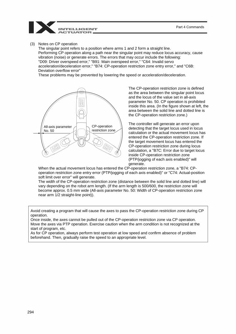
294
Part 4 Commands
(3) Notes on CP operation
The singular point refers to a position where arms 1 and 2 form a straight line. Performing CP operation along a path near the singular point may reduce locus accuracy, cause vibration (noise) or generate errors. The errors that may occur include the following: "D09: Driver overspeed error," "B91: Main overspeed error," "C64: Invalid servo acceleration/deceleration error," "B74: CP-operation restriction zone entry error," and "C6B: Deviation overflow error" These problems may be prevented by lowering the speed or acceleration/deceleration.
The CP-operation restriction zone is defined as the area between the singular point locus and the locus of the value set in all-axis parameter No. 50. CP operation is prohibited inside this area. (In the figure shown at left, the area between the solid line and dotted line is the CP-operation restriction zone.)
The controller will generate an error upon detecting that the target locus used in locus calculation or the actual movement locus has entered the CP-operation restriction zone. If the target movement locus has entered the CP-operation restriction zone during locus calculation, a "B7C: Error due to target locus inside CP-operation restriction zone (PTP/jogging of each axis enabled)" will generate.
When the actual movement locus has entered the CP-operation restriction zone, a "B74: CP-operation restriction zone entry error (PTP/jogging of each axis enabled)" or "C74: Actual-position soft limit over error" will generate. The width of the CP-operation restriction zone (distance between the solid line and dotted line) will vary depending on the robot arm length. (If the arm length is 500/600, the restriction zone will become approx. 0.5 mm wide (All-axis parameter No. 50: Width of CP-operation restriction zone near arm 1/2 straight-line point)).
Avoid creating a program that will cause the axes to pass the CP-operation restriction zone during CP operation. Once inside, the axes cannot be pulled out of the CP-operation restriction zone via CP operation. Move the axes via PTP operation. Exercise caution when the arm condition is not recognized at the start of program, etc. As for CP operation, always perform test operation at low speed and confirm absence of problem beforehand. Then, gradually raise the speed to an appropriate level.
All-axis parameter No. 50
CP-operation restriction zone
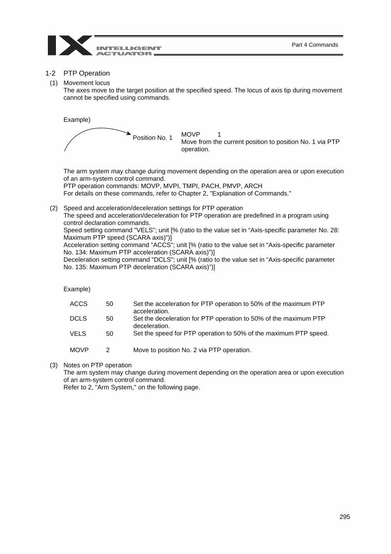
295
Part 4 Commands
1-2 PTP Operation
(1) Movement locus The axes move to the target position at the specified speed. The locus of axis tip during movement cannot be specified using commands.
Example)
MOVP 1 Move from the current position to position No. 1 via PTP operation.
The arm system may change during movement depending on the operation area or upon execution of an arm-system control command. PTP operation commands: MOVP, MVPI, TMPI, PACH, PMVP, ARCH For details on these commands, refer to Chapter 2, "Explanation of Commands."
(2) Speed and acceleration/deceleration settings for PTP operation
The speed and acceleration/deceleration for PTP operation are predefined in a program using control declaration commands. Speed setting command "VELS"; unit [% (ratio to the value set in “Axis-specific parameter No. 28: Maximum PTP speed (SCARA axis)”)] Acceleration setting command "ACCS"; unit [% (ratio to the value set in “Axis-specific parameter No. 134: Maximum PTP acceleration (SCARA axis)”)] Deceleration setting command "DCLS"; unit [% (ratio to the value set in “Axis-specific parameter No. 135: Maximum PTP deceleration (SCARA axis)”)]
Example)
ACCS 50 Set the acceleration for PTP operation to 50% of the maximum PTP acceleration.
DCLS 50 Set the deceleration for PTP operation to 50% of the maximum PTP deceleration.
VELS 50 Set the speed for PTP operation to 50% of the maximum PTP speed. MOVP 2 Move to position No. 2 via PTP operation.
(3) Notes on PTP operation
The arm system may change during movement depending on the operation area or upon execution of an arm-system control command. Refer to 2, "Arm System," on the following page.
Position No. 1
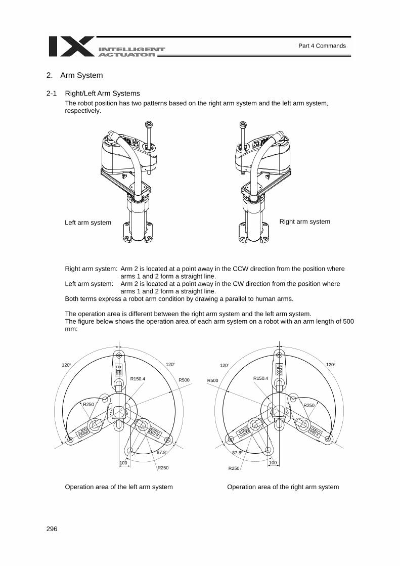
296
Part 4 Commands
2. Arm System 2-1 Right/Left Arm Systems
The robot position has two patterns based on the right arm system and the left arm system, respectively.
Right arm system: Arm 2 is located at a point away in the CCW direction from the position where arms 1 and 2 form a straight line.
Left arm system: Arm 2 is located at a point away in the CW direction from the position where arms 1 and 2 form a straight line.
Both terms express a robot arm condition by drawing a parallel to human arms.
The operation area is different between the right arm system and the left arm system. The figure below shows the operation area of each arm system on a robot with an arm length of 500 mm:
Operation area of the left arm system Operation area of the right arm system
Left arm system Right arm system
120° 120°
R500 R150.4
R250
100 R250
87.8°
120° 120°
R500 R150.4
R250 100
R250
87.8°
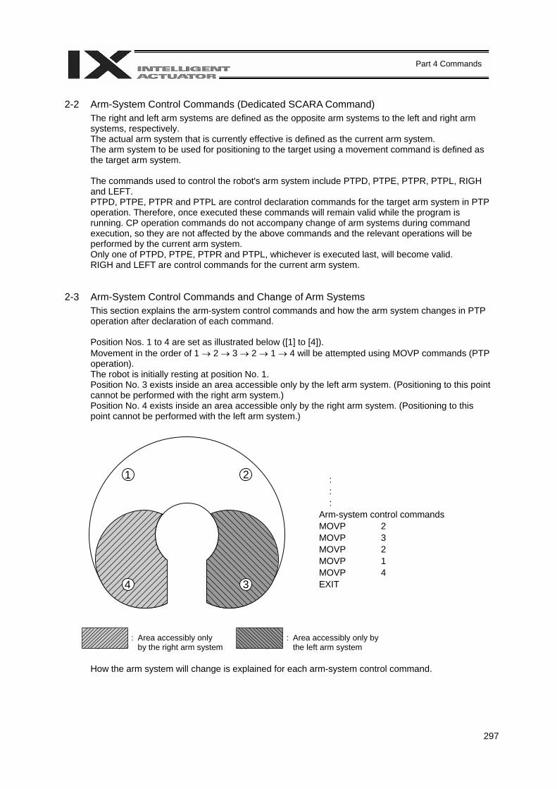
297
Part 4 Commands
2-2 Arm-System Control Commands (Dedicated SCARA Command)
The right and left arm systems are defined as the opposite arm systems to the left and right arm systems, respectively. The actual arm system that is currently effective is defined as the current arm system. The arm system to be used for positioning to the target using a movement command is defined as the target arm system. The commands used to control the robot's arm system include PTPD, PTPE, PTPR, PTPL, RIGH and LEFT. PTPD, PTPE, PTPR and PTPL are control declaration commands for the target arm system in PTP operation. Therefore, once executed these commands will remain valid while the program is running. CP operation commands do not accompany change of arm systems during command execution, so they are not affected by the above commands and the relevant operations will be performed by the current arm system. Only one of PTPD, PTPE, PTPR and PTPL, whichever is executed last, will become valid. RIGH and LEFT are control commands for the current arm system.
2-3 Arm-System Control Commands and Change of Arm Systems
This section explains the arm-system control commands and how the arm system changes in PTP operation after declaration of each command.
Position Nos. 1 to 4 are set as illustrated below ([1] to [4]). Movement in the order of 1 → 2 → 3 → 2 → 1 → 4 will be attempted using MOVP commands (PTP operation). The robot is initially resting at position No. 1. Position No. 3 exists inside an area accessible only by the left arm system. (Positioning to this point cannot be performed with the right arm system.) Position No. 4 exists inside an area accessible only by the right arm system. (Positioning to this point cannot be performed with the left arm system.)
: : : Arm-system control commands MOVP 2 MOVP 3 MOVP 2 MOVP 1 MOVP 4 EXIT
How the arm system will change is explained for each arm-system control command.
1 2
34
: Area accessibly only by the right arm system
: Area accessibly only by the left arm system

298
Part 4 Commands
In the figure, a black arrow indicates a movement involving change of arm systems. A white arrow indicates a movement not involving change of arm systems. The striped arm represents the right arm system, while the white arm represents the left arm system.
(1) PTPD
After a PTPD command is executed, the robot will move the current arm system to perform positioning. The PTPD command prohibits the current arm system and target arm system from becoming the opposite arm systems. Attempting a movement to an area where positioning is possible only with the opposite arm system will generate an error (C73: Target-locus soft limit over error). When a program is started, the robot is already in a PTPD-declared mode even before executing a PTPD command. a. Starting with the right arm system
: : : PTPD MOVP 2 MOVP 3 ⇒ C73 error will generate.
b. Starting with the left arm system
: : : PTPD MOVP 2 MOVP 3 MOVP 2 MOVP 1 MOVP 4 ⇒ C73 error will generate.
1 2
34
1 2
34
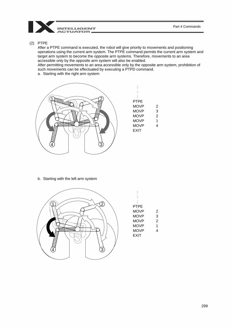
299
Part 4 Commands
(2) PTPE
After a PTPE command is executed, the robot will give priority to movements and positioning operations using the current arm system. The PTPE command permits the current arm system and target arm system to become the opposite arm systems. Therefore, movements to an area accessible only by the opposite arm system will also be enabled. After permitting movements to an area accessible only by the opposite arm system, prohibition of such movements can be effectuated by executing a PTPD command. a. Starting with the right arm system
: : : PTPE MOVP 2 MOVP 3 MOVP 2 MOVP 1 MOVP 4 EXIT
b. Starting with the left arm system
: : : PTPE MOVP 2 MOVP 3 MOVP 2 MOVP 1 MOVP 4 EXIT
1 2
34
1 2
34
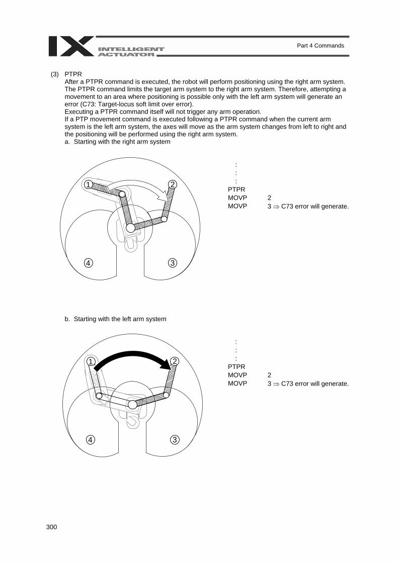
300
Part 4 Commands
(3) PTPR
After a PTPR command is executed, the robot will perform positioning using the right arm system. The PTPR command limits the target arm system to the right arm system. Therefore, attempting a movement to an area where positioning is possible only with the left arm system will generate an error (C73: Target-locus soft limit over error). Executing a PTPR command itself will not trigger any arm operation. If a PTP movement command is executed following a PTPR command when the current arm system is the left arm system, the axes will move as the arm system changes from left to right and the positioning will be performed using the right arm system. a. Starting with the right arm system
: : : PTPR MOVP 2 MOVP 3 ⇒ C73 error will generate.
b. Starting with the left arm system
: : : PTPR MOVP 2 MOVP 3 ⇒ C73 error will generate.
1 2
34
1 2
34
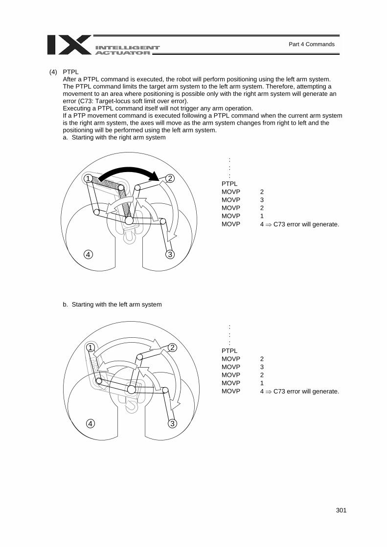
301
Part 4 Commands
(4) PTPL
After a PTPL command is executed, the robot will perform positioning using the left arm system. The PTPL command limits the target arm system to the left arm system. Therefore, attempting a movement to an area where positioning is possible only with the right arm system will generate an error (C73: Target-locus soft limit over error). Executing a PTPL command itself will not trigger any arm operation. If a PTP movement command is executed following a PTPL command when the current arm system is the right arm system, the axes will move as the arm system changes from right to left and the positioning will be performed using the left arm system. a. Starting with the right arm system
: : : PTPL MOVP 2 MOVP 3 MOVP 2 MOVP 1 MOVP 4 ⇒ C73 error will generate.
b. Starting with the left arm system
: : : PTPL MOVP 2 MOVP 3 MOVP 2 MOVP 1 MOVP 4 ⇒ C73 error will generate.
1 2
34
1 2
34
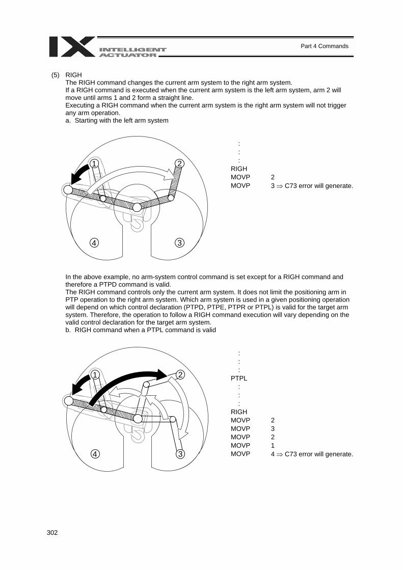
302
Part 4 Commands
(5) RIGH
The RIGH command changes the current arm system to the right arm system. If a RIGH command is executed when the current arm system is the left arm system, arm 2 will move until arms 1 and 2 form a straight line. Executing a RIGH command when the current arm system is the right arm system will not trigger any arm operation. a. Starting with the left arm system
: : : RIGH MOVP 2 MOVP 3 ⇒ C73 error will generate.
In the above example, no arm-system control command is set except for a RIGH command and therefore a PTPD command is valid. The RIGH command controls only the current arm system. It does not limit the positioning arm in PTP operation to the right arm system. Which arm system is used in a given positioning operation will depend on which control declaration (PTPD, PTPE, PTPR or PTPL) is valid for the target arm system. Therefore, the operation to follow a RIGH command execution will vary depending on the valid control declaration for the target arm system. b. RIGH command when a PTPL command is valid
: : : PTPL : : : RIGH MOVP 2 MOVP 3 MOVP 2 MOVP 1 MOVP 4 ⇒ C73 error will generate.
1 2
34
1 2
34
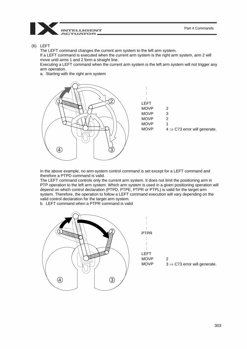
303
Part 4 Commands
(6) LEFT
The LEFT command changes the current arm system to the left arm system. If a LEFT command is executed when the current arm system is the right arm system, arm 2 will move until arms 1 and 2 form a straight line. Executing a LEFT command when the current arm system is the left arm system will not trigger any arm operation. a. Starting with the right arm system
: : : LEFT MOVP 2 MOVP 3 MOVP 2 MOVP 1 MOVP 4 ⇒ C73 error will generate.
In the above example, no arm-system control command is set except for a LEFT command and therefore a PTPD command is valid. The LEFT command controls only the current arm system. It does not limit the positioning arm in PTP operation to the left arm system. Which arm system is used in a given positioning operation will depend on which control declaration (PTPD, PTPE, PTPR or PTPL) is valid for the target arm system. Therefore, the operation to follow a LEFT command execution will vary depending on the valid control declaration for the target arm system. b. LEFT command when a PTPR command is valid
: : : PTPR : : : LEFT MOVP 2 MOVP 3 ⇒ C73 error will generate.
1 2
34
1 2
34
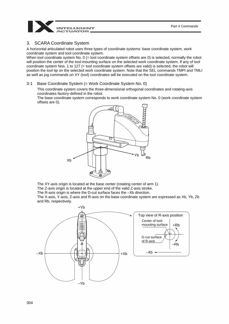
304
Part 4 Commands
3. SCARA Coordinate System A horizontal articulated robot uses three types of coordinate systems: base coordinate system, work coordinate system and tool coordinate system. When tool coordinate system No. 0 (= tool coordinate system offsets are 0) is selected, normally the robot will position the center of the tool-mounting surface on the selected work coordinate system. If any of tool coordinate system Nos. 1 to 127 (= tool coordinate system offsets are valid) is selected, the robot will position the tool tip on the selected work coordinate system. Note that the SEL commands TMPI and TMLI as well as jog commands on XY (tool) coordinates will be executed on the tool coordinate system. 3-1 Base Coordinate System (= Work Coordinate System No. 0)
This coordinate system covers the three-dimensional orthogonal coordinates and rotating-axis coordinates factory-defined in the robot. The base coordinate system corresponds to work coordinate system No. 0 (work coordinate system offsets are 0).
The XY-axis origin is located at the base center (rotating center of arm 1). The Z-axis origin is located at the upper end of the valid Z-axis stroke. The R-axis origin is where the D-cut surface faces the –Xb direction. The X-axis, Y-axis, Z-axis and R-axis on the base coordinate system are expressed as Xb, Yb, Zb and Rb, respectively.
Xb Yb
Rb
Zb
+Yb
–Yb
–Xb +Xb
Top view of R-axis position Center of tool-mounting surface
D-cut surface of R-axis
+Rb
–Rb
–Xb
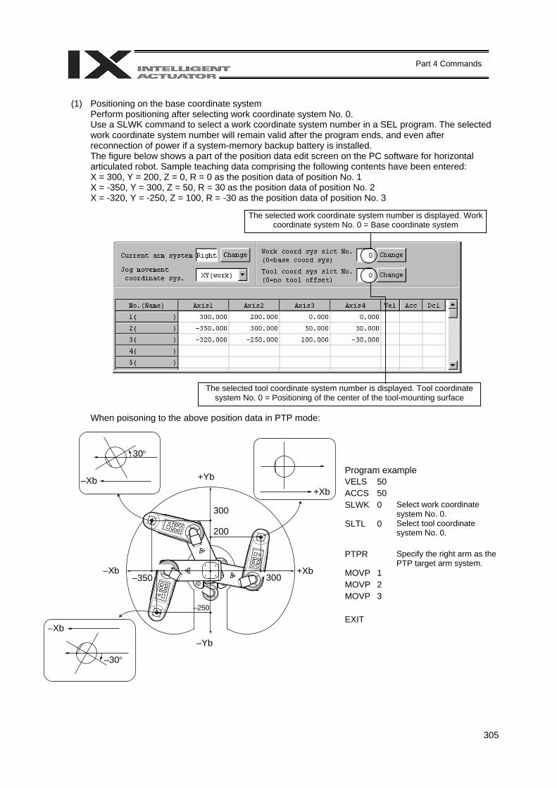
305
Part 4 Commands
(1) Positioning on the base coordinate system
Perform positioning after selecting work coordinate system No. 0. Use a SLWK command to select a work coordinate system number in a SEL program. The selected work coordinate system number will remain valid after the program ends, and even after reconnection of power if a system-memory backup battery is installed. The figure below shows a part of the position data edit screen on the PC software for horizontal articulated robot. Sample teaching data comprising the following contents have been entered: X = 300, Y = 200, Z = 0, R = 0 as the position data of position No. 1 X = -350, Y = 300, Z = 50, R = 30 as the position data of position No. 2 X = -320, Y = -250, Z = 100, R = -30 as the position data of position No. 3
When poisoning to the above position data in PTP mode:
Program example VELS 50 ACCS 50 SLWK 0 Select work coordinate
system No. 0. SLTL 0 Select tool coordinate
system No. 0. PTPR Specify the right arm as the
PTP target arm system. MOVP 1 MOVP 2 MOVP 3 EXIT
The selected work coordinate system number is displayed. Work coordinate system No. 0 = Base coordinate system
The selected tool coordinate system number is displayed. Tool coordinate system No. 0 = Positioning of the center of the tool-mounting surface
+Yb
–Yb
–Xb +Xb
+Xb –Xb
–Xb
30°
–30°
–350
–250
300
300 200
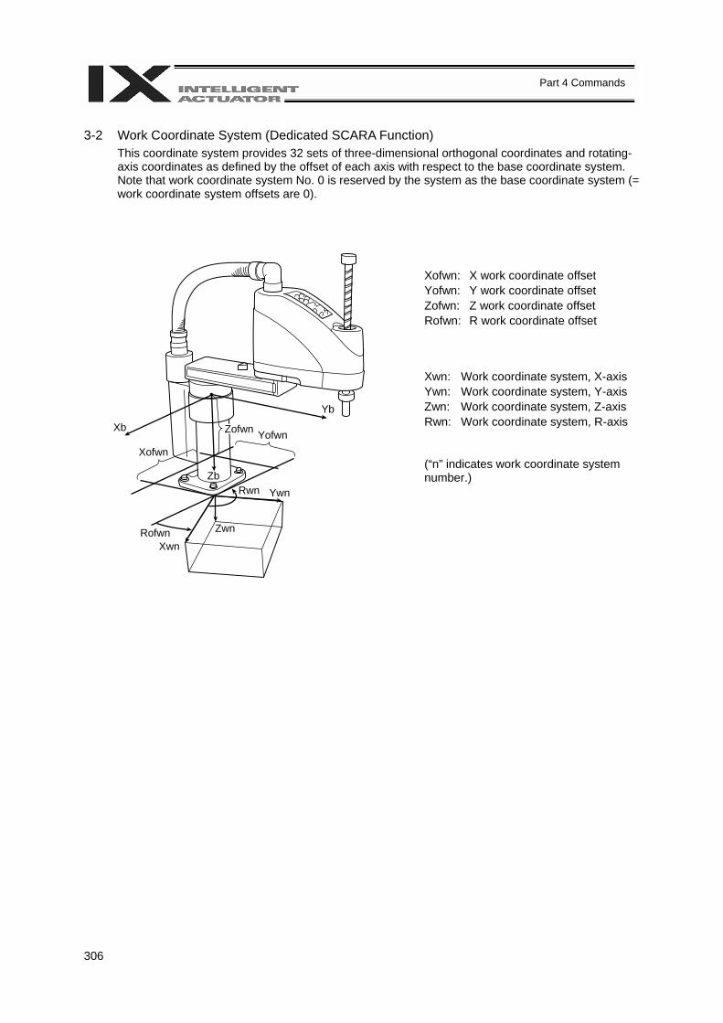
306
Part 4 Commands
3-2 Work Coordinate System (Dedicated SCARA Function)
This coordinate system provides 32 sets of three-dimensional orthogonal coordinates and rotating-axis coordinates as defined by the offset of each axis with respect to the base coordinate system. Note that work coordinate system No. 0 is reserved by the system as the base coordinate system (= work coordinate system offsets are 0).
Xofwn: X work coordinate offset Yofwn: Y work coordinate offset Zofwn: Z work coordinate offset Rofwn: R work coordinate offset
Xwn: Work coordinate system, X-axis Ywn: Work coordinate system, Y-axis Zwn: Work coordinate system, Z-axis Rwn: Work coordinate system, R-axis (“n” indicates work coordinate system number.)
Xb
Yb
Zofwn
Xofwn Yofwn
Zb
Rofwn Xwn
Zwn
Rwn Ywn
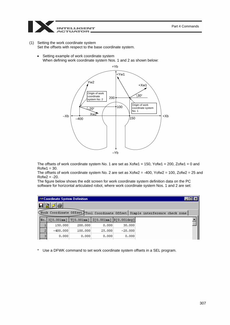
307
Part 4 Commands
(1) Setting the work coordinate system
Set the offsets with respect to the base coordinate system.
• Setting example of work coordinate system When defining work coordinate system Nos. 1 and 2 as shown below:
The offsets of work coordinate system No. 1 are set as Xofw1 = 150, Yofw1 = 200, Zofw1 = 0 and Rofw1 = 30. The offsets of work coordinate system No. 2 are set as Xofw2 = -400, Yofw2 = 100, Zofw2 = 25 and Rofw2 = -20. The figure below shows the edit screen for work coordinate system definition data on the PC software for horizontal articulated robot, where work coordinate system Nos. 1 and 2 are set:
* Use a DFWK command to set work coordinate system offsets in a SEL program.
Origin of work coordinate system No. 1
Origin of work coordinate system No. 2
–Yb
30°
+Yb
200
100
Yw2
–Xb –400
–20° Xw2
+Yw1
+Xw1
+Xb 150
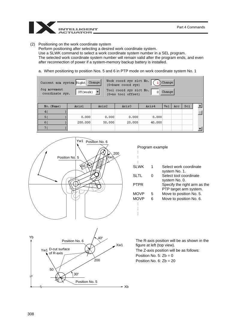
308
Part 4 Commands
(2) Positioning on the work coordinate system
Perform positioning after selecting a desired work coordinate system. Use a SLWK command to select a work coordinate system number in a SEL program. The selected work coordinate system number will remain valid after the program ends, and even after reconnection of power if a system-memory backup battery is installed.
a. When positioning to position Nos. 5 and 6 in PTP mode on work coordinate system No. 1
Program example : : : SLWK 1 Select work coordinate
system No. 1. SLTL 0 Select tool coordinate
system No. 0. PTPR Specify the right arm as the
PTP target arm system. MOVP 5 Move to position No. 5. MOVP 6 Move to position No. 6. : : :
The R-axis position will be as shown in the figure at left (top view). The Z-axis position will be as follows: Position No. 5: Zb = 0 Position No. 6: Zb = 20
Position No. 5
Position No. 6
200
Yw1
Xw1
50
D-cut surface of R-axis
Position No. 6
Position No. 5
Yw1 Xw1
30° 50
Yb
Xb
40°
200
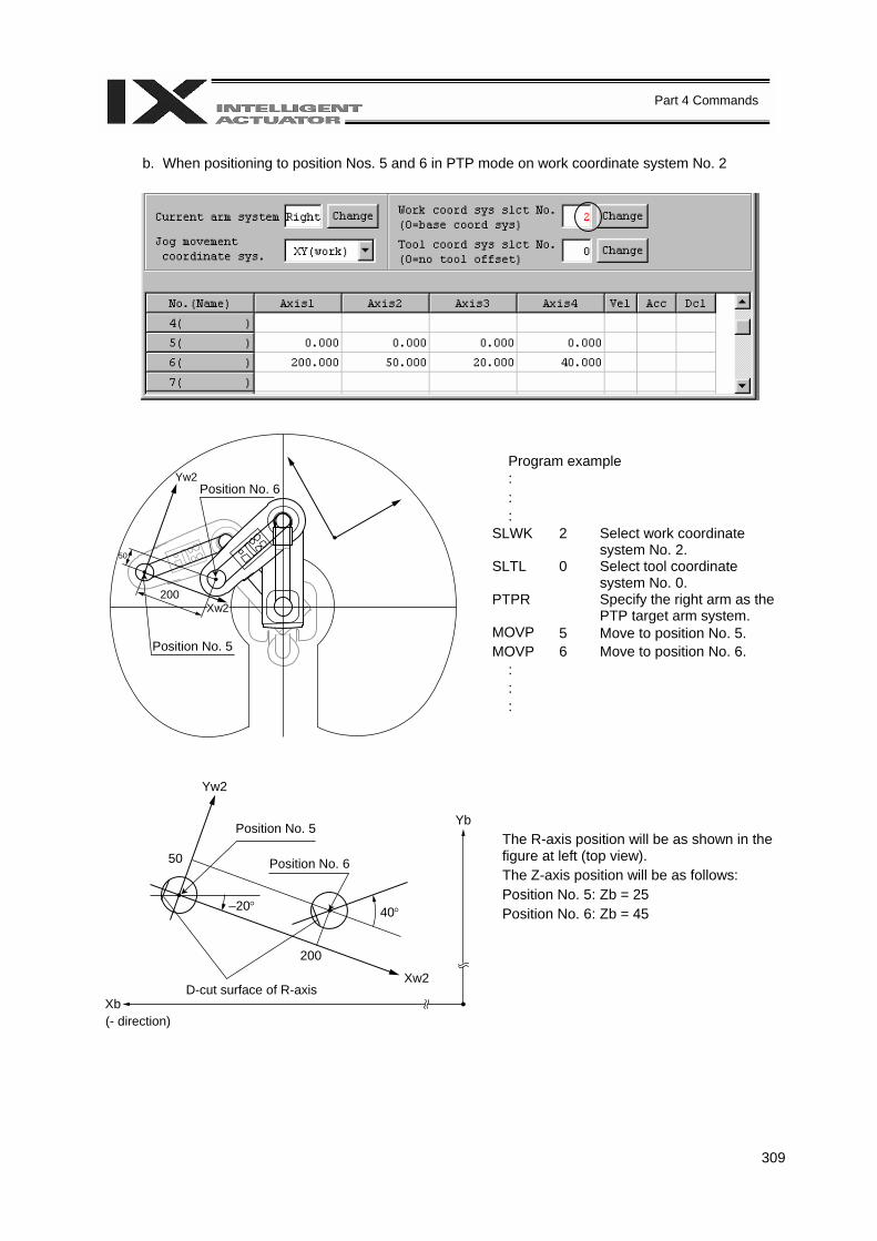
309
Part 4 Commands
b. When positioning to position Nos. 5 and 6 in PTP mode on work coordinate system No. 2
Program example : : : SLWK 2 Select work coordinate
system No. 2. SLTL 0 Select tool coordinate
system No. 0. PTPR Specify the right arm as the
PTP target arm system. MOVP 5 Move to position No. 5. MOVP 6 Move to position No. 6. : : :
The R-axis position will be as shown in the figure at left (top view). The Z-axis position will be as follows: Position No. 5: Zb = 25 Position No. 6: Zb = 45
Position No. 6
Position No. 5
200
Yw2
Xw2
50
D-cut surface of R-axis
Position No. 6
Position No. 5
Yw2
Xw2
–20°
50
Yb
Xb
40°
200
(- direction)
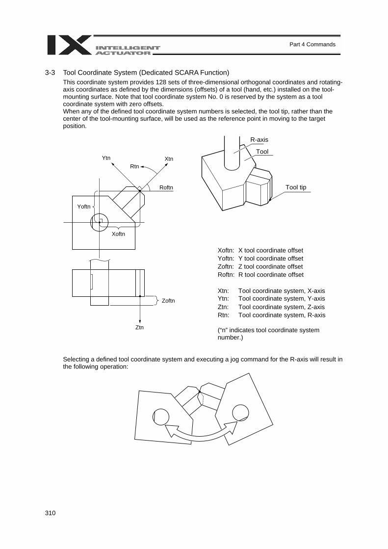
310
Part 4 Commands
3-3 Tool Coordinate System (Dedicated SCARA Function)
This coordinate system provides 128 sets of three-dimensional orthogonal coordinates and rotating-axis coordinates as defined by the dimensions (offsets) of a tool (hand, etc.) installed on the tool-mounting surface. Note that tool coordinate system No. 0 is reserved by the system as a tool coordinate system with zero offsets. When any of the defined tool coordinate system numbers is selected, the tool tip, rather than the center of the tool-mounting surface, will be used as the reference point in moving to the target position.
Xoftn: X tool coordinate offset Yoftn: Y tool coordinate offset Zoftn: Z tool coordinate offset Roftn: R tool coordinate offset Xtn: Tool coordinate system, X-axis Ytn: Tool coordinate system, Y-axis Ztn: Tool coordinate system, Z-axis Rtn: Tool coordinate system, R-axis (“n” indicates tool coordinate system number.)
Selecting a defined tool coordinate system and executing a jog command for the R-axis will result in the following operation:
R-axis
Tool
Tool tip
Ytn Rtn
Xtn
Roftn
Yoftn
Xoftn
Zoftn
Ztn
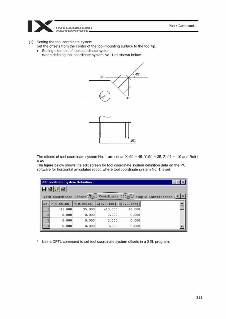
311
Part 4 Commands
(1) Setting the tool coordinate system
Set the offsets from the center of the tool-mounting surface to the tool tip. • Setting example of tool coordinate system
When defining tool coordinate system No. 1 as shown below:
The offsets of tool coordinate system No. 1 are set as Xoft1 = 45, Yoft1 = 35, Zoft1 = -10 and Roft1 = 45. The figure below shows the edit screen for tool coordinate system definition data on the PC software for horizontal articulated robot, where tool coordinate system No. 1 is set:
* Use a DFTL command to set tool coordinate system offsets in a SEL program.
35
0
45°
45
10
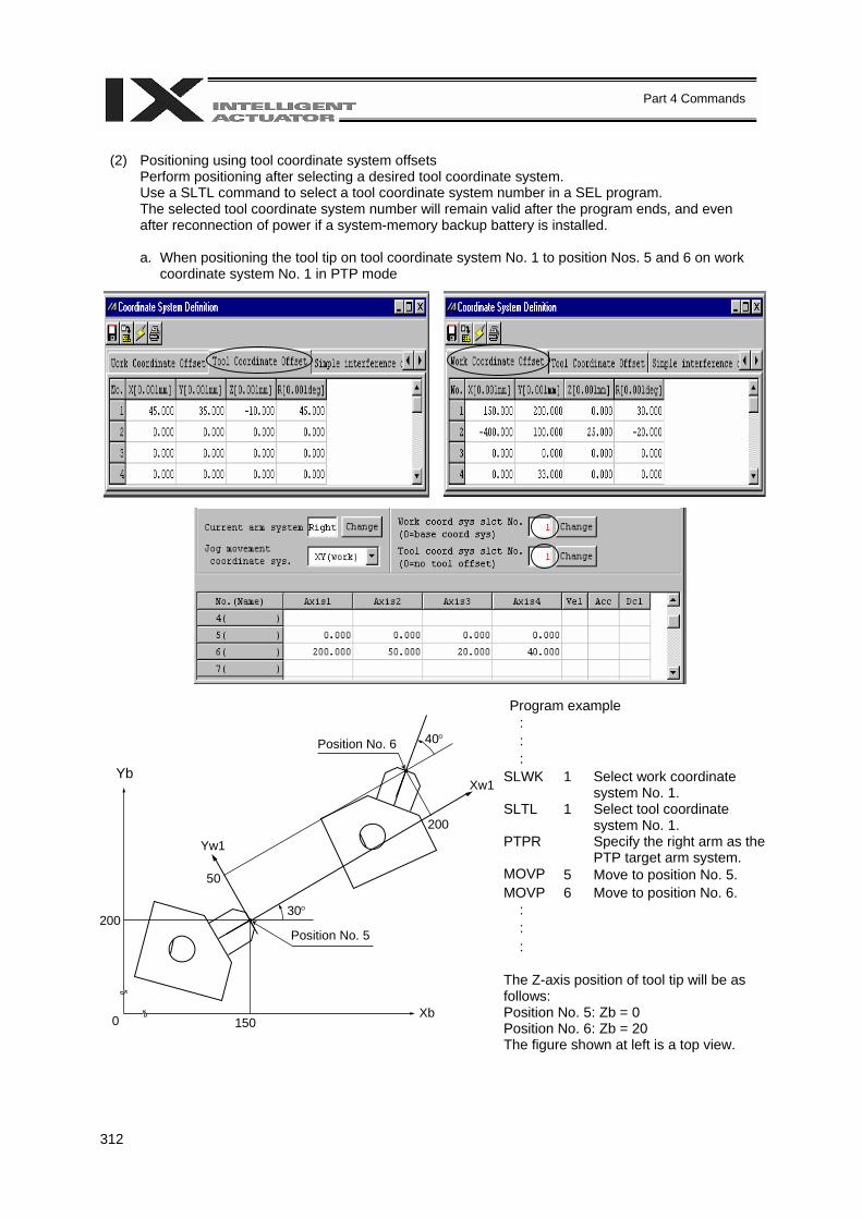
312
Part 4 Commands
(2) Positioning using tool coordinate system offsets
Perform positioning after selecting a desired tool coordinate system. Use a SLTL command to select a tool coordinate system number in a SEL program. The selected tool coordinate system number will remain valid after the program ends, and even after reconnection of power if a system-memory backup battery is installed.
a. When positioning the tool tip on tool coordinate system No. 1 to position Nos. 5 and 6 on work
coordinate system No. 1 in PTP mode
Program example
: : : SLWK 1 Select work coordinate
system No. 1. SLTL 1 Select tool coordinate
system No. 1. PTPR Specify the right arm as the
PTP target arm system. MOVP 5 Move to position No. 5. MOVP 6 Move to position No. 6. : : : The Z-axis position of tool tip will be as follows: Position No. 5: Zb = 0 Position No. 6: Zb = 20 The figure shown at left is a top view.
Position No. 6
200
Xw1
50
Position No. 5
Yw1
200
0 150 Xb
40°
Yb
30°
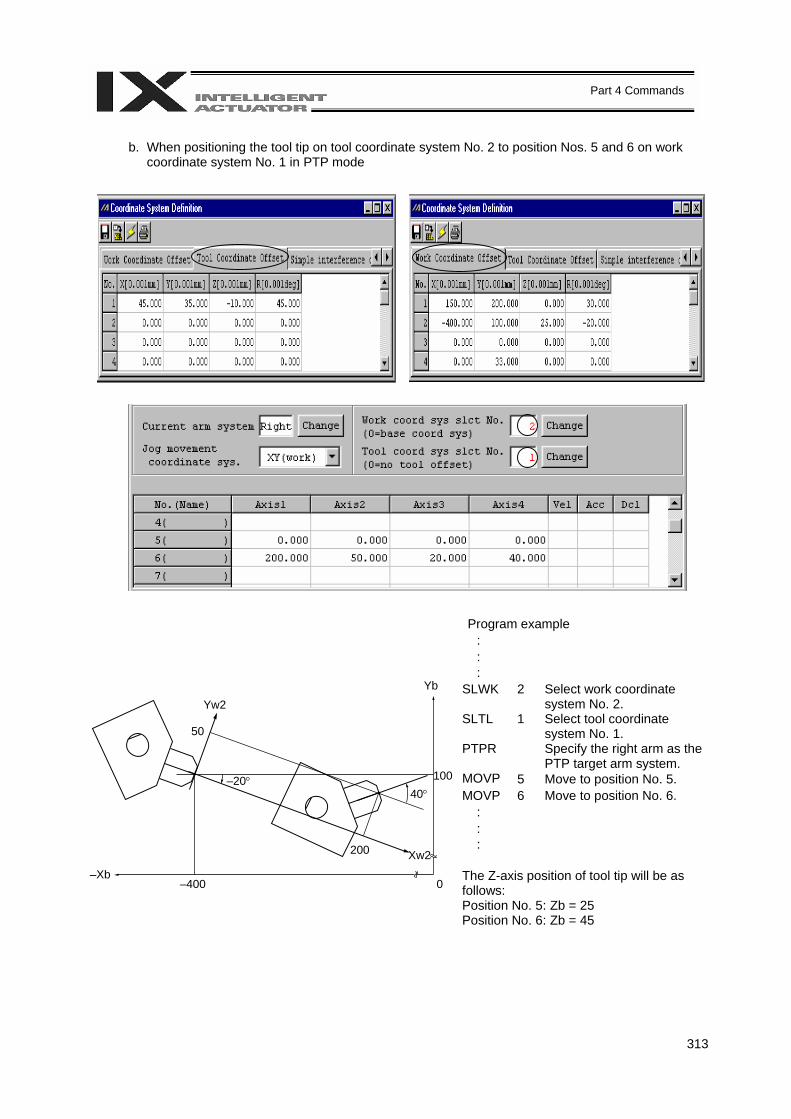
313
Part 4 Commands
b. When positioning the tool tip on tool coordinate system No. 2 to position Nos. 5 and 6 on work
coordinate system No. 1 in PTP mode
Program example : : : SLWK 2 Select work coordinate
system No. 2. SLTL 1 Select tool coordinate
system No. 1. PTPR Specify the right arm as the
PTP target arm system. MOVP 5 Move to position No. 5. MOVP 6 Move to position No. 6. : : : The Z-axis position of tool tip will be as follows: Position No. 5: Zb = 25 Position No. 6: Zb = 45
100
Yb
50
Yw2
200 Xw2
40° –20°
–400 0 –Xb

314
Part 4 Commands
4. Simple Interference Check Zone (Dedicated SCARA Function) The simple interference check zone is an area set for the purpose of checking possible interference between the robot and peripherals. In the case of tool coordinate system No. 0 (= tool coordinate system offsets are 0), entry into the simple interference check zone can be detected based on the center of the tool-mounting surface. In the case of tool coordinate system Nos. 1 to 127 (= tool coordinate offsets are valid), entry into the check zone can be detected based on the tool tip.
(1) Notes on use of simple interference check zone Entry into the simple interference check zone of the center of the tool-mounting surface (when tool coordinate system No. 0 is selected) or the tool tip (when any of tool coordinate system Nos. 1 to 127 is selected) is detected. Entry of the R-axis periphery or parts other than the tool tip will not be detected.
This function does not prevent entry into the simple interference check zone. It only detects that the specified part has entered the zone. Entry into the simple interference check zone cannot be detected reliably unless the entered part stays in the zone for at least 5 msec. The function is designed as a simple check during low-speed operation. The locus is different between high-speed operation (operation at the actual operating speed) and low-speed operation. Provide a sufficient margin to prevent interference. (During high-speed operation, the locus tends to shift inward compared with during low-speed operation.) The definition coordinates of simple interference check zone are always treated as data on the base coordinate system (work coordinate system No. 0). Therefore, changing the work coordinate system will not change the position of the simple interference check zone. Exercise caution. After changing the definition coordinates of simple interference check zone, it will take at least 5 msec before the new settings are reflected in the check result. During PTP operation, movements will not follow specified paths. When moving near an interfering object (including the robot itself), always perform test operation at low speed and confirm absence of interference, and then gradually raise the speed to an appropriate level.
(2) Setting the simple interference check zone
The simple interference check zone is set using position data on the base coordinate system. Enter the maximum and minimum values defining the simple interference check zone. Set the boundaries of the simple interference check zone in parallel with the base coordinate axes.
To set the rectangular solid shown at left as a simple interference check zone, enter coordinates of two points corresponding to one of the combinations of (A)-(G), (B)-(H), (C)-(E) and (D)-(F).
AB
C DEF
G H
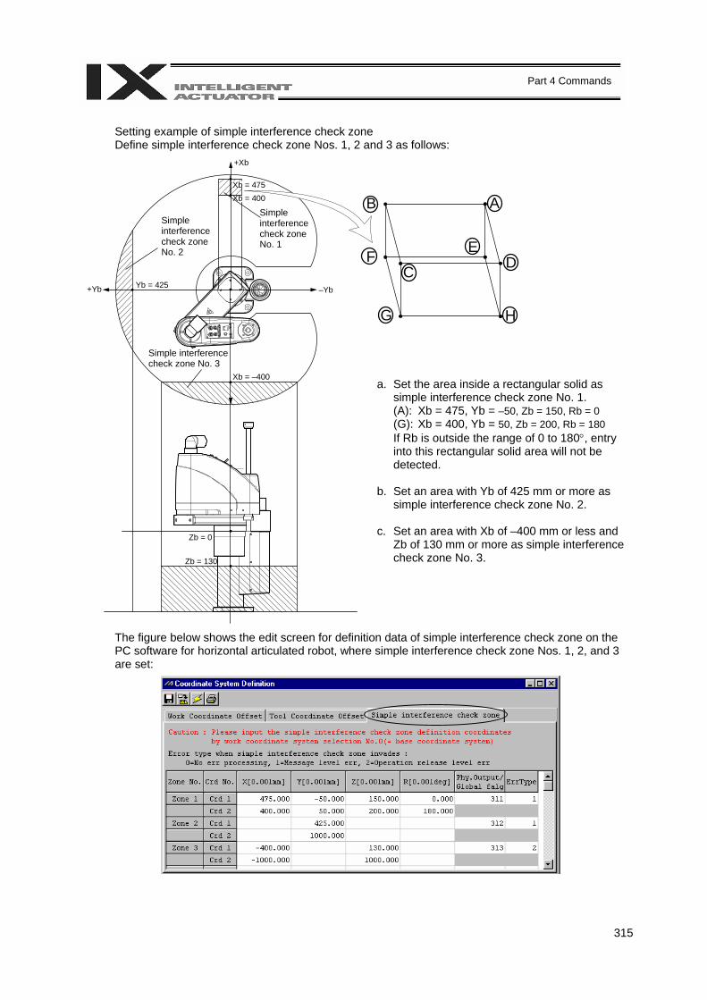
315
Part 4 Commands
AB
C DEF
G H
Setting example of simple interference check zone Define simple interference check zone Nos. 1, 2 and 3 as follows:
a. Set the area inside a rectangular solid as simple interference check zone No. 1. (A): Xb = 475, Yb = –50, Zb = 150, Rb = 0 (G): Xb = 400, Yb = 50, Zb = 200, Rb = 180 If Rb is outside the range of 0 to 180°, entry into this rectangular solid area will not be detected.
b. Set an area with Yb of 425 mm or more as
simple interference check zone No. 2. c. Set an area with Xb of –400 mm or less and
Zb of 130 mm or more as simple interference check zone No. 3.
The figure below shows the edit screen for definition data of simple interference check zone on the PC software for horizontal articulated robot, where simple interference check zone Nos. 1, 2, and 3 are set:
Simple interference check zone No. 1
Simple interference check zone No. 2
Simple interference check zone No. 3
+Xb
Xb = 475
Xb = 400
–Yb +Yb Yb = 425
Xb = –400
Zb = 0
Zb = 130
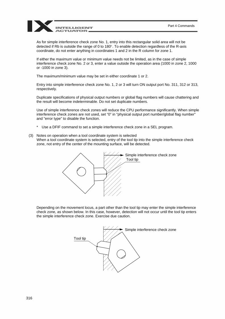
316
Part 4 Commands
As for simple interference check zone No. 1, entry into this rectangular solid area will not be detected if Rb is outside the range of 0 to 180°. To enable detection regardless of the R-axis coordinate, do not enter anything in coordinates 1 and 2 in the R column for zone 1. If either the maximum value or minimum value needs not be limited, as in the case of simple interference check zone No. 2 or 3, enter a value outside the operation area (1000 in zone 2, 1000 or -1000 in zone 3). The maximum/minimum value may be set in either coordinate 1 or 2. Entry into simple interference check zone No. 1, 2 or 3 will turn ON output port No. 311, 312 or 313, respectively. Duplicate specifications of physical output numbers or global flag numbers will cause chattering and the result will become indeterminable. Do not set duplicate numbers.
Use of simple interference check zones will reduce the CPU performance significantly. When simple interference check zones are not used, set “0” in "physical output port number/global flag number" and "error type" to disable the function.
* Use a DFIF command to set a simple interference check zone in a SEL program.
(3) Notes on operation when a tool coordinate system is selected
When a tool coordinate system is selected, entry of the tool tip into the simple interference check zone, not entry of the center of the mounting surface, will be detected.
Depending on the movement locus, a part other than the tool tip may enter the simple interference check zone, as shown below. In this case, however, detection will not occur until the tool tip enters the simple interference check zone. Exercise due caution.
Simple interference check zone Tool tip
Tool tip
Simple interference check zone
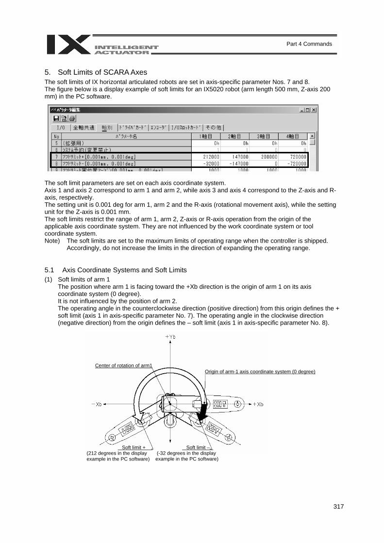
317
Part 4 Commands
5. Soft Limits of SCARA Axes The soft limits of IX horizontal articulated robots are set in axis-specific parameter Nos. 7 and 8. The figure below is a display example of soft limits for an IX5020 robot (arm length 500 mm, Z-axis 200 mm) in the PC software. The soft limit parameters are set on each axis coordinate system. Axis 1 and axis 2 correspond to arm 1 and arm 2, while axis 3 and axis 4 correspond to the Z-axis and R-axis, respectively. The setting unit is 0.001 deg for arm 1, arm 2 and the R-axis (rotational movement axis), while the setting unit for the Z-axis is 0.001 mm. The soft limits restrict the range of arm 1, arm 2, Z-axis or R-axis operation from the origin of the applicable axis coordinate system. They are not influenced by the work coordinate system or tool coordinate system. Note) The soft limits are set to the maximum limits of operating range when the controller is shipped.
Accordingly, do not increase the limits in the direction of expanding the operating range. 5.1 Axis Coordinate Systems and Soft Limits (1) Soft limits of arm 1
The position where arm 1 is facing toward the +Xb direction is the origin of arm 1 on its axis coordinate system (0 degree). It is not influenced by the position of arm 2. The operating angle in the counterclockwise direction (positive direction) from this origin defines the + soft limit (axis 1 in axis-specific parameter No. 7). The operating angle in the clockwise direction (negative direction) from the origin defines the – soft limit (axis 1 in axis-specific parameter No. 8).
Center of rotation of arm1 Origin of arm-1 axis coordinate system (0 degree)
Soft limit + (212 degrees in the display example in the PC software)
Soft limit – (-32 degrees in the display example in the PC software)

318
Part 4 Commands
(2) Soft limits of arm 2
The position where arm 2 is crossing with arm 1 at right angles is the origin of arm 2 on its axis coordinate system (0 degree). It is not influenced by the angle position of arm 1. The operating angle in the counterclockwise direction (positive direction) from this origin defines the + soft limit (axis 2 in axis-specific parameter No. 7). The operating angle in the clockwise direction (negative direction) from the origin defines the – soft limit (axis 2 in axis-specific parameter No. 8).
(3) Soft limits of the Z-axis
The position where the mechanical stopper attached to the Z-axis is approx. 5 mm below the mechanical end at the bottom of arm 2 is the origin of the Z-axis on its axis coordinate system (0 mm). This is the same position as where axis 3, which defines the base coordinate system, is at 0 mm. (With cleanroom and dustproof/splash-proof specifications, the mechanical stoppers are housed inside the bellows and therefore not visible.) The downward direction (positive direction) from this origin defines the + soft limit (axis 3 in axis-specific parameter No. 7). The upward direction (negative direction) defines the – soft limit (axis 3 in axis-specific parameter No. 8). (The directions are reversed for inverse specifications.)
Origin of arm-2 axis coordinate system (0 degree)
Center of rotation of arm 2
Soft limit + (147 degrees in the display example in the PC software)
Soft limit – (-147 degrees in the display example in the PC software)
Origin of Z-axis coordinate system (0 mm)
(200 mm in the display example in the PC software)
Soft limit +
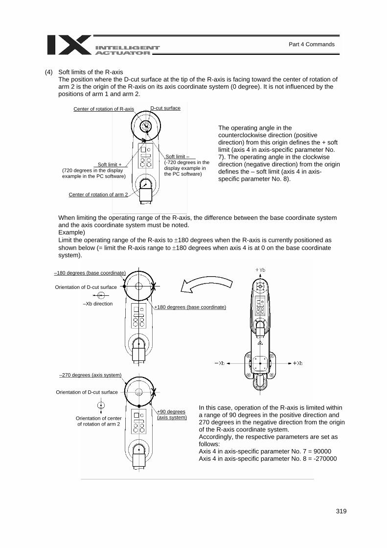
319
Part 4 Commands
(4) Soft limits of the R-axis
The position where the D-cut surface at the tip of the R-axis is facing toward the center of rotation of arm 2 is the origin of the R-axis on its axis coordinate system (0 degree). It is not influenced by the positions of arm 1 and arm 2.
When limiting the operating range of the R-axis, the difference between the base coordinate system and the axis coordinate system must be noted. Example) Limit the operating range of the R-axis to ±180 degrees when the R-axis is currently positioned as shown below (= limit the R-axis range to ±180 degrees when axis 4 is at 0 on the base coordinate system).
The operating angle in the counterclockwise direction (positive direction) from this origin defines the + soft limit (axis 4 in axis-specific parameter No. 7). The operating angle in the clockwise direction (negative direction) from the origin defines the – soft limit (axis 4 in axis-specific parameter No. 8).
Center of rotation of R-axis D-cut surface
Soft limit + (720 degrees in the display example in the PC software)
Center of rotation of arm 2
Soft limit – (-720 degrees in the display example in the PC software)
–180 degrees (base coordinate)
Orientation of D-cut surface
–Xb direction +180 degrees (base coordinate)
–270 degrees (axis system)
Orientation of D-cut surface
Orientation of center of rotation of arm 2
+90 degrees (axis system)
In this case, operation of the R-axis is limited within a range of 90 degrees in the positive direction and 270 degrees in the negative direction from the origin of the R-axis coordinate system. Accordingly, the respective parameters are set as follows: Axis 4 in axis-specific parameter No. 7 = 90000 Axis 4 in axis-specific parameter No. 8 = -270000
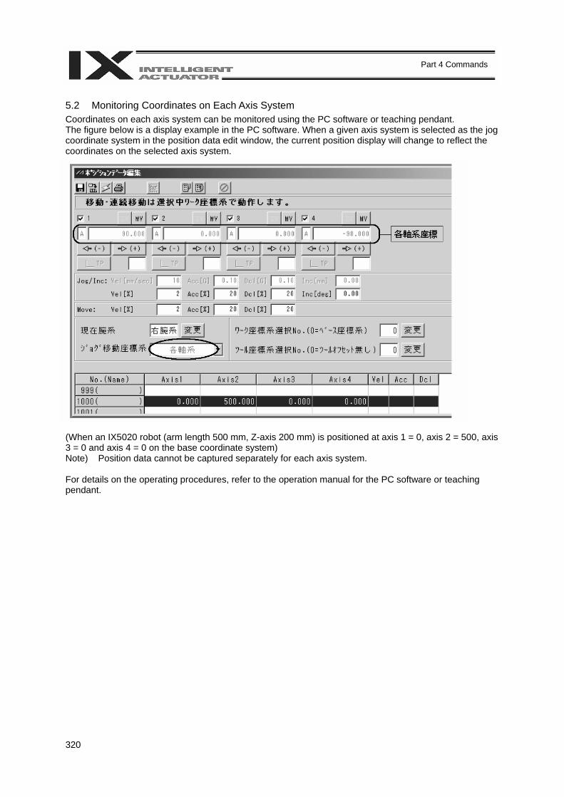
320
Part 4 Commands
5.2 Monitoring Coordinates on Each Axis System Coordinates on each axis system can be monitored using the PC software or teaching pendant. The figure below is a display example in the PC software. When a given axis system is selected as the jog coordinate system in the position data edit window, the current position display will change to reflect the coordinates on the selected axis system. (When an IX5020 robot (arm length 500 mm, Z-axis 200 mm) is positioned at axis 1 = 0, axis 2 = 500, axis 3 = 0 and axis 4 = 0 on the base coordinate system) Note) Position data cannot be captured separately for each axis system. For details on the operating procedures, refer to the operation manual for the PC software or teaching pendant.
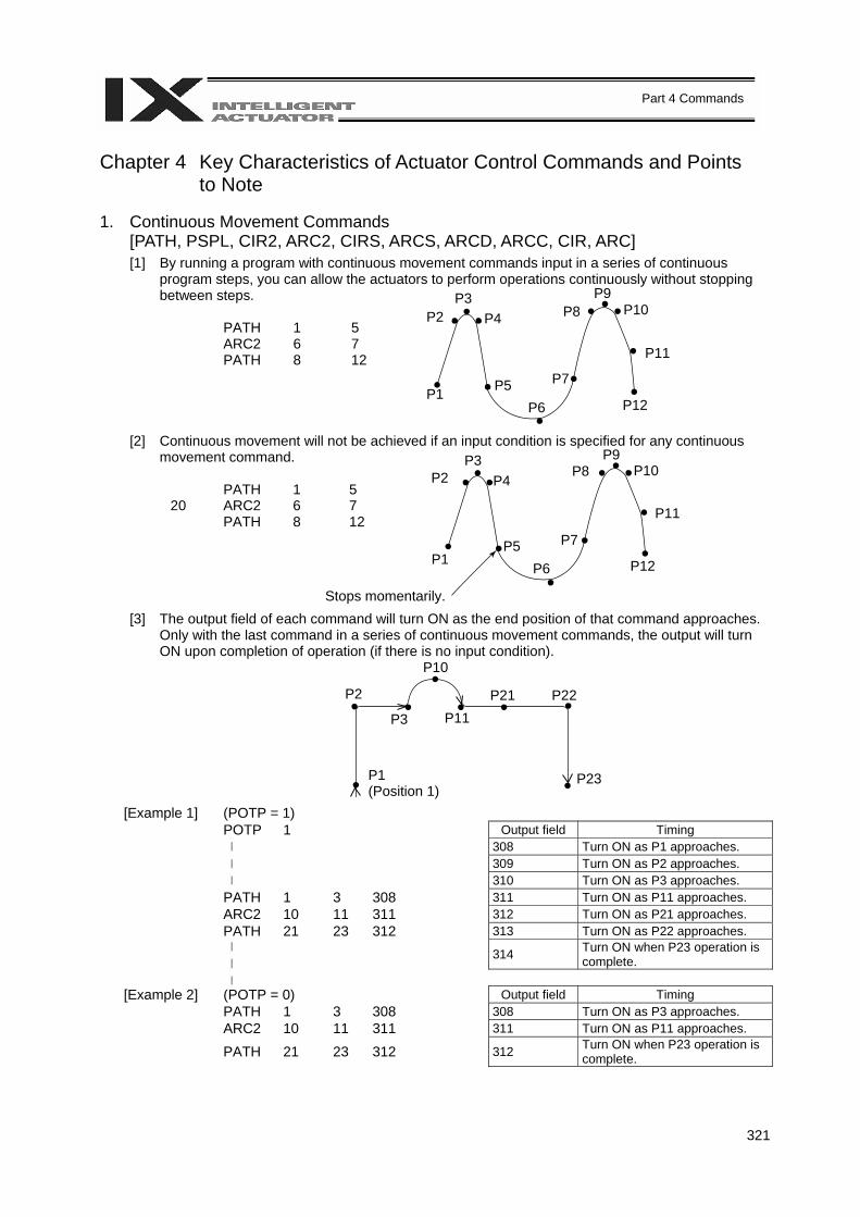
321
Part 4 Commands
Chapter 4 Key Characteristics of Actuator Control Commands and Points to Note
1. Continuous Movement Commands
[PATH, PSPL, CIR2, ARC2, CIRS, ARCS, ARCD, ARCC, CIR, ARC] [1] By running a program with continuous movement commands input in a series of continuous
program steps, you can allow the actuators to perform operations continuously without stopping between steps.
PATH 1 5 ARC2 6 7 PATH 8 12
[2] Continuous movement will not be achieved if an input condition is specified for any continuous movement command.
PATH 1 5 20 ARC2 6 7 PATH 8 12
[3] The output field of each command will turn ON as the end position of that command approaches. Only with the last command in a series of continuous movement commands, the output will turn ON upon completion of operation (if there is no input condition).
(POTP = 1) [Example 1] POTP 1
Output field Timing 308 Turn ON as P1 approaches. 309 Turn ON as P2 approaches. 310 Turn ON as P3 approaches. PATH 1 3 308 311 Turn ON as P11 approaches. ARC2 10 11 311 312 Turn ON as P21 approaches. PATH 21 23 312 313 Turn ON as P22 approaches. 314 Turn ON when P23 operation is
complete. [Example 2] (POTP = 0) Output field Timing PATH 1 3 308 308 Turn ON as P3 approaches. ARC2 10 11 311 311 Turn ON as P11 approaches. PATH 21 23 312 312 Turn ON when P23 operation is
complete.
Stops momentarily.
P1 (Position 1)
P3 P2 P4
P1 P5 P6
P7
P8 P9
P10
P12
P3 P2 P4
P1 P5
P6
P7
P8 P9
P10
P11
P12
P3
P2
P10
P23
P11 P21 P22
P11
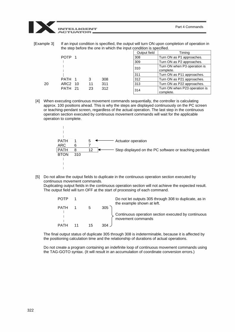
322
Part 4 Commands
[Example 3] If an input condition is specified, the output will turn ON upon completion of operation in
the step before the one in which the input condition is specified. Output field Timing POTP 1 308 Turn ON as P1 approaches. 309 Turn ON as P2 approaches. 310 Turn ON when P3 operation is
complete. 311 Turn ON as P11 approaches. PATH 1 3 308 312 Turn ON as P21 approaches.
20 ARC2 10 11 311 313 Turn ON as P22 approaches. PATH 21 23 312 314 Turn ON when P23 operation is
complete.
[4] When executing continuous movement commands sequentially, the controller is calculating approx. 100 positions ahead. This is why the steps are displayed continuously on the PC screen or teaching-pendant screen, regardless of the actual operation. The last step in the continuous operation section executed by continuous movement commands will wait for the applicable operation to complete.
PATH 1 5 Actuator operation ARC 6 7 PATH 8 12 Step displayed on the PC software or teaching pendant BTON 310
[5] Do not allow the output fields to duplicate in the continuous operation section executed by
continuous movement commands. Duplicating output fields in the continuous operation section will not achieve the expected result. The output field will turn OFF at the start of processing of each command.
POTP 1 Do not let outputs 305 through 308 to duplicate, as in the example shown at left.
PATH 1 5 305
Continuous operation section executed by continuous
movement commands
PATH 11 15 304
The final output status of duplicate 305 through 308 is indeterminable, because it is affected by the positioning calculation time and the relationship of durations of actual operations. Do not create a program containing an indefinite loop of continuous movement commands using the TAG-GOTO syntax. (It will result in an accumulation of coordinate conversion errors.)
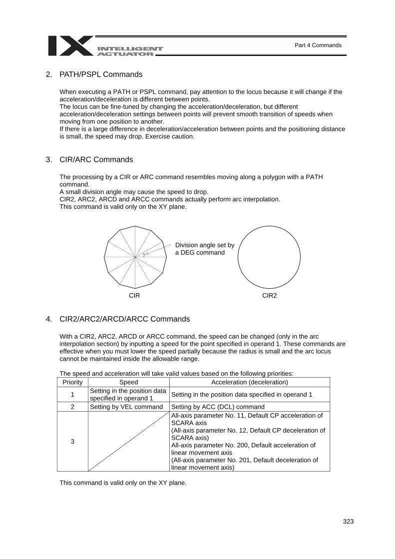
323
Part 4 Commands
2. PATH/PSPL Commands
When executing a PATH or PSPL command, pay attention to the locus because it will change if the acceleration/deceleration is different between points. The locus can be fine-tuned by changing the acceleration/deceleration, but different acceleration/deceleration settings between points will prevent smooth transition of speeds when moving from one position to another. If there is a large difference in deceleration/acceleration between points and the positioning distance is small, the speed may drop. Exercise caution.
3. CIR/ARC Commands
The processing by a CIR or ARC command resembles moving along a polygon with a PATH command. A small division angle may cause the speed to drop. CIR2, ARC2, ARCD and ARCC commands actually perform arc interpolation. This command is valid only on the XY plane.
4. CIR2/ARC2/ARCD/ARCC Commands
With a CIR2, ARC2, ARCD or ARCC command, the speed can be changed (only in the arc interpolation section) by inputting a speed for the point specified in operand 1. These commands are effective when you must lower the speed partially because the radius is small and the arc locus cannot be maintained inside the allowable range. The speed and acceleration will take valid values based on the following priorities: Priority Speed Acceleration (deceleration)
1 Setting in the position data specified in operand 1 Setting in the position data specified in operand 1
2 Setting by VEL command Setting by ACC (DCL) command
3
All-axis parameter No. 11, Default CP acceleration of SCARA axis (All-axis parameter No. 12, Default CP deceleration of SCARA axis) All-axis parameter No. 200, Default acceleration of linear movement axis (All-axis parameter No. 201, Default deceleration of linear movement axis)
This command is valid only on the XY plane.
Division angle set by a DEG command
CIR CIR2
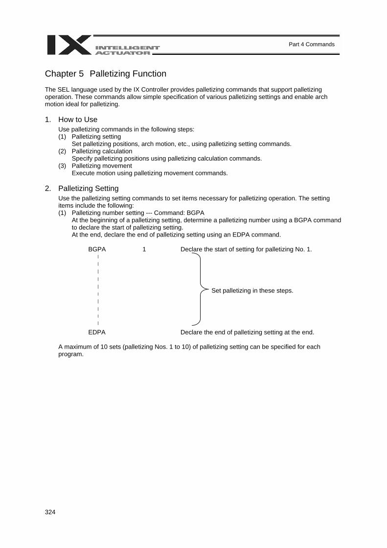
324
Part 4 Commands
Chapter 5 Palletizing Function The SEL language used by the IX Controller provides palletizing commands that support palletizing operation. These commands allow simple specification of various palletizing settings and enable arch motion ideal for palletizing. 1. How to Use
Use palletizing commands in the following steps: (1) Palletizing setting
Set palletizing positions, arch motion, etc., using palletizing setting commands. (2) Palletizing calculation
Specify palletizing positions using palletizing calculation commands. (3) Palletizing movement
Execute motion using palletizing movement commands. 2. Palletizing Setting
Use the palletizing setting commands to set items necessary for palletizing operation. The setting items include the following: (1) Palletizing number setting --- Command: BGPA
At the beginning of a palletizing setting, determine a palletizing number using a BGPA command to declare the start of palletizing setting. At the end, declare the end of palletizing setting using an EDPA command.
BGPA 1 Declare the start of setting for palletizing No. 1. Set palletizing in these steps.
EDPA Declare the end of palletizing setting at the end.
A maximum of 10 sets (palletizing Nos. 1 to 10) of palletizing setting can be specified for each program.
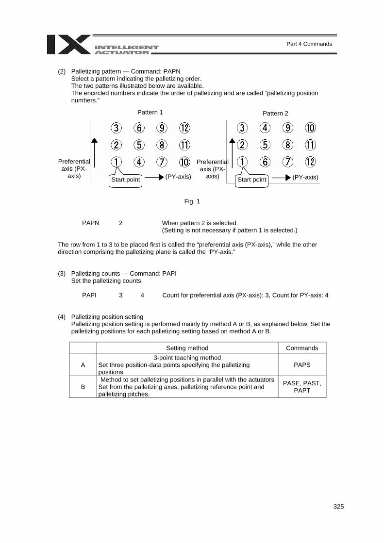
325
Part 4 Commands
(2) Palletizing pattern --- Command: PAPN
Select a pattern indicating the palletizing order. The two patterns illustrated below are available. The encircled numbers indicate the order of palletizing and are called “palletizing position numbers.”
Fig. 1
PAPN 2 When pattern 2 is selected (Setting is not necessary if pattern 1 is selected.)
The row from 1 to 3 to be placed first is called the “preferential axis (PX-axis),” while the other direction comprising the palletizing plane is called the “PY-axis.”
(3) Palletizing counts --- Command: PAPI Set the palletizing counts.
PAPI 3 4 Count for preferential axis (PX-axis): 3, Count for PY-axis: 4
(4) Palletizing position setting Palletizing position setting is performed mainly by method A or B, as explained below. Set the palletizing positions for each palletizing setting based on method A or B.
Setting method Commands
A 3-point teaching method
Set three position-data points specifying the palletizing positions.
PAPS
B Method to set palletizing positions in parallel with the actuators
Set from the palletizing axes, palletizing reference point and palletizing pitches.
PASE, PAST, PAPT
Pattern 1 Pattern 2
Preferential axis (PX-
axis)
Preferential axis (PX-
axis) Start point (PY-axis) (PY-axis) Start point
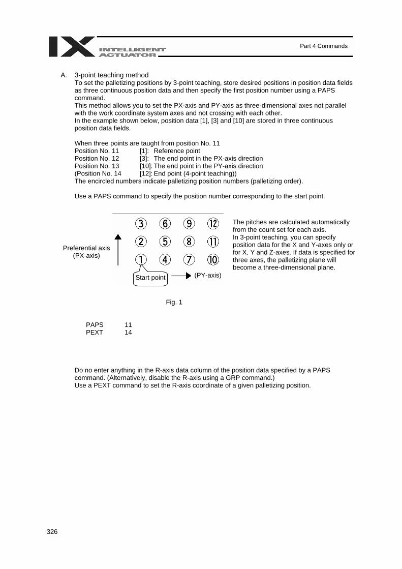
326
Part 4 Commands
A. 3-point teaching method
To set the palletizing positions by 3-point teaching, store desired positions in position data fields as three continuous position data and then specify the first position number using a PAPS command. This method allows you to set the PX-axis and PY-axis as three-dimensional axes not parallel with the work coordinate system axes and not crossing with each other. In the example shown below, position data [1], [3] and [10] are stored in three continuous position data fields. When three points are taught from position No. 11 Position No. 11 [1]: Reference point Position No. 12 [3]: The end point in the PX-axis direction Position No. 13 [10]: The end point in the PY-axis direction (Position No. 14 [12]: End point (4-point teaching)) The encircled numbers indicate palletizing position numbers (palletizing order). Use a PAPS command to specify the position number corresponding to the start point.
Fig. 1
PAPS 11 PEXT 14
Do no enter anything in the R-axis data column of the position data specified by a PAPS command. (Alternatively, disable the R-axis using a GRP command.) Use a PEXT command to set the R-axis coordinate of a given palletizing position.
Preferential axis (PX-axis)
Start point (PY-axis)
The pitches are calculated automatically from the count set for each axis. In 3-point teaching, you can specify position data for the X and Y-axes only or for X, Y and Z-axes. If data is specified for three axes, the palletizing plane will become a three-dimensional plane.
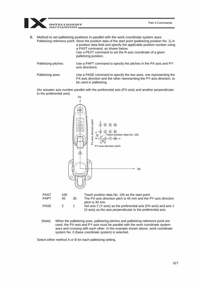
327
Part 4 Commands
B. Method to set palletizing positions in parallel with the work coordinate system axes
Palletizing reference point: Store the position data of the start point (palletizing position No. 1) in a position data field and specify the applicable position number using a PAST command, as shown below. Use a PEXT command to set the R-axis coordinate of a given palletizing position.
Palletizing pitches: Use a PAPT command to specify the pitches in the PX-axis and PY-
axis directions. Palletizing axes: Use a PASE command to specify the two axes, one representing the
PX-axis direction and the other representing the PY-axis direction, to be used in palletizing.
(An actuator axis number parallel with the preferential axis (PX-axis) and another perpendicular to the preferential axis)
PAST 100 Teach position data No. 100 as the start point. PAPT 45 30 The PX-axis direction pitch is 45 mm and the PY-axis direction
pitch is 30 mm. PASE 2 1 Set axis 2 (Y-axis) as the preferential axis (PX-axis) and axis 1
(X-axis) as the axis perpendicular to the preferential axis.
(Note) When the palletizing axes, palletizing pitches and palletizing reference point are used, the PX-axis and PY-axis must be parallel with the work coordinate system axes and crossing with each other. In the example shown above, work coordinate system No. 0 (base coordinate system) is selected.
Select either method A or B for each palletizing setting.
PX-
axis
dire
ctio
n pi
tch
45
30
Teach position data No. 100.
Xb
PY-axis direction pitch
Yb
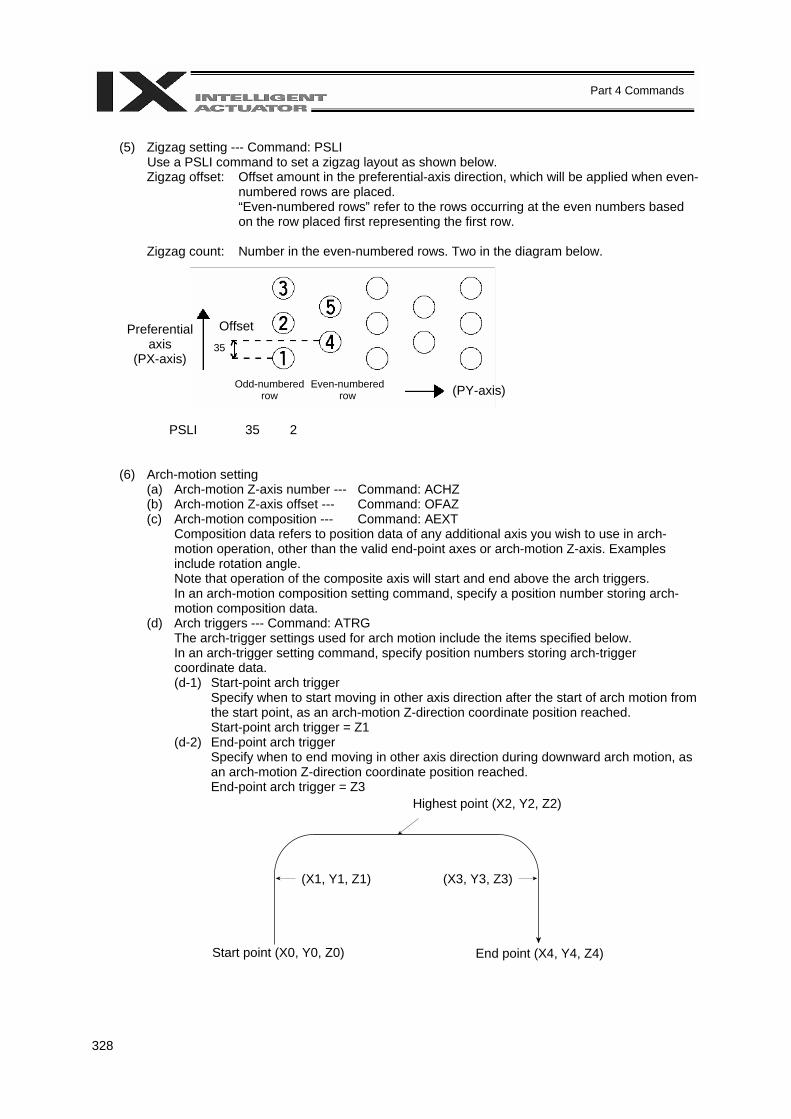
328
Part 4 Commands
(5) Zigzag setting --- Command: PSLI
Use a PSLI command to set a zigzag layout as shown below. Zigzag offset: Offset amount in the preferential-axis direction, which will be applied when even-
numbered rows are placed. “Even-numbered rows” refer to the rows occurring at the even numbers based on the row placed first representing the first row.
Zigzag count: Number in the even-numbered rows. Two in the diagram below.
PSLI 35 2
(6) Arch-motion setting
(a) Arch-motion Z-axis number --- Command: ACHZ (b) Arch-motion Z-axis offset --- Command: OFAZ (c) Arch-motion composition --- Command: AEXT
Composition data refers to position data of any additional axis you wish to use in arch-motion operation, other than the valid end-point axes or arch-motion Z-axis. Examples include rotation angle. Note that operation of the composite axis will start and end above the arch triggers. In an arch-motion composition setting command, specify a position number storing arch-motion composition data.
(d) Arch triggers --- Command: ATRG The arch-trigger settings used for arch motion include the items specified below. In an arch-trigger setting command, specify position numbers storing arch-trigger coordinate data. (d-1) Start-point arch trigger
Specify when to start moving in other axis direction after the start of arch motion from the start point, as an arch-motion Z-direction coordinate position reached. Start-point arch trigger = Z1
(d-2) End-point arch trigger Specify when to end moving in other axis direction during downward arch motion, as an arch-motion Z-direction coordinate position reached. End-point arch trigger = Z3
Preferential axis
(PX-axis)
Offset 35
Odd-numbered row (PY-axis) Even-numbered
row
Highest point (X2, Y2, Z2)
Start point (X0, Y0, Z0) End point (X4, Y4, Z4)
(X1, Y1, Z1) (X3, Y3, Z3)
329
Part 4 Commands
(7) Palletizing arch-motion setting
(a) Palletizing Z-direction axis number --- Command: PCHZ (Dedicated SCARA command) (b) Palletizing Z-axis offset --- Command: OFPZ (Dedicated SCARA command) (c) Palletizing composition --- Command: PEXT (Dedicated SCARA command)
Composition data refers to position data of any additional axis you wish to use with palletizing movement commands, other than the PX, PY (and PZ)-axes. Use a PEXT command to set the R-axis position coordinates of a given palletizing position. Note that operation of the composite axis will start and end above the palletizing arch triggers. In a palletizing-composition setting command, specify a position number storing palletizing composition data.
(d) Palletizing arch triggers --- Command: PTRG (Dedicated SCARA command)
If the end point is a palletizing point, a palletizing arch trigger must be set just like an arch trigger. In a palletizing arch-trigger setting command, specify position numbers storing palletizing arch-trigger coordinate data. (d-1) Palletizing start-point arch trigger (d-2) Palletizing end-point arch trigger
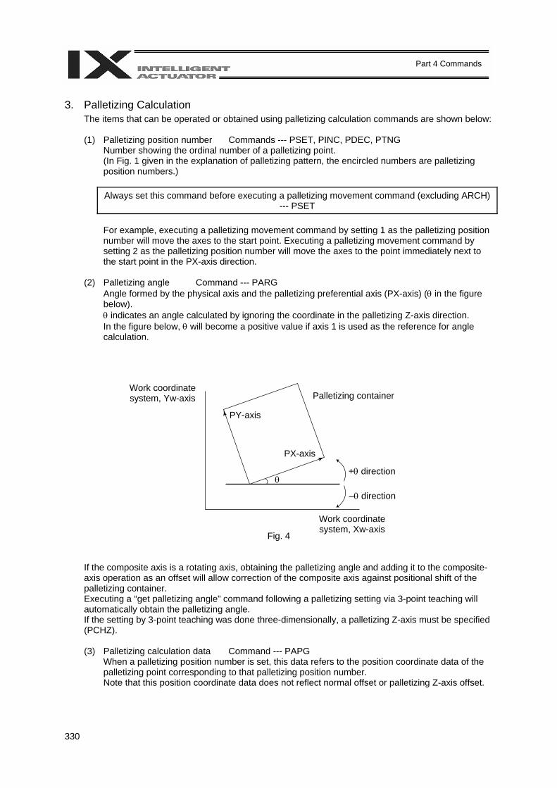
330
Part 4 Commands
3. Palletizing Calculation
The items that can be operated or obtained using palletizing calculation commands are shown below:
(1) Palletizing position number Commands --- PSET, PINC, PDEC, PTNG Number showing the ordinal number of a palletizing point. (In Fig. 1 given in the explanation of palletizing pattern, the encircled numbers are palletizing position numbers.)
Always set this command before executing a palletizing movement command (excluding ARCH)
--- PSET
For example, executing a palletizing movement command by setting 1 as the palletizing position number will move the axes to the start point. Executing a palletizing movement command by setting 2 as the palletizing position number will move the axes to the point immediately next to the start point in the PX-axis direction.
(2) Palletizing angle Command --- PARG
Angle formed by the physical axis and the palletizing preferential axis (PX-axis) (θ in the figure below). θ indicates an angle calculated by ignoring the coordinate in the palletizing Z-axis direction. In the figure below, θ will become a positive value if axis 1 is used as the reference for angle calculation.
Fig. 4
If the composite axis is a rotating axis, obtaining the palletizing angle and adding it to the composite-axis operation as an offset will allow correction of the composite axis against positional shift of the palletizing container. Executing a “get palletizing angle” command following a palletizing setting via 3-point teaching will automatically obtain the palletizing angle. If the setting by 3-point teaching was done three-dimensionally, a palletizing Z-axis must be specified (PCHZ). (3) Palletizing calculation data Command --- PAPG
When a palletizing position number is set, this data refers to the position coordinate data of the palletizing point corresponding to that palletizing position number. Note that this position coordinate data does not reflect normal offset or palletizing Z-axis offset.
Work coordinate system, Yw-axis Palletizing container
PY-axis
PX-axis
–θ direction
+θ direction θ
Work coordinate system, Xw-axis

331
Part 4 Commands
4. Palletizing Movement
Palletizing movement commands include those used to move to a palletizing point and one used to move to an end point specified by position data. (1) Movement commands to palletizing point --- PMVP, PMVL (Dedicated linear movement axis
command), PACH (Dedicated SCALA command) Position coordinates of a two-dimensionally or three-dimensionally placed palletizing point are calculated and movement is performed using the calculated point as the end point. (The axes will move to the palletizing point of the palletizing position number specified in the executed command.)
PMVP: Move from the current position to a palletizing point via PTP. PMVL: Move from the current position to a palletizing point via interpolation. PACH: Move from the current position to a palletizing point via arch motion.
Palletizing arch motion must be set in a palletizing setting.
PCHZ 3 PTRG 11 13 PACH 1 12
Highest point of arch motion Position No. 12
Start-point arch trigger Position No. 13
End-point arch trigger Position No. 11
Start point End point Position No. 10
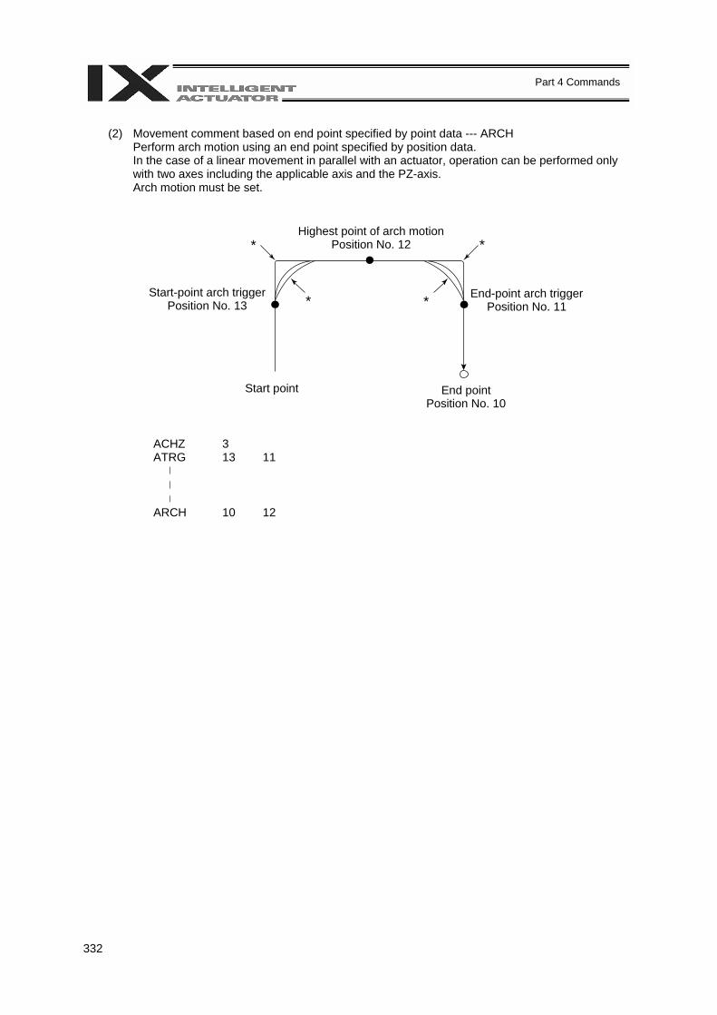
332
Part 4 Commands
(2) Movement comment based on end point specified by point data --- ARCH
Perform arch motion using an end point specified by position data. In the case of a linear movement in parallel with an actuator, operation can be performed only with two axes including the applicable axis and the PZ-axis. Arch motion must be set.
ACHZ 3 ATRG 13 11 ARCH 10 12
Highest point of arch motion
Position No. 12
Start-point arch trigger Position No. 13
End-point arch trigger Position No. 11
Start point End point Position No. 10
* *
* *
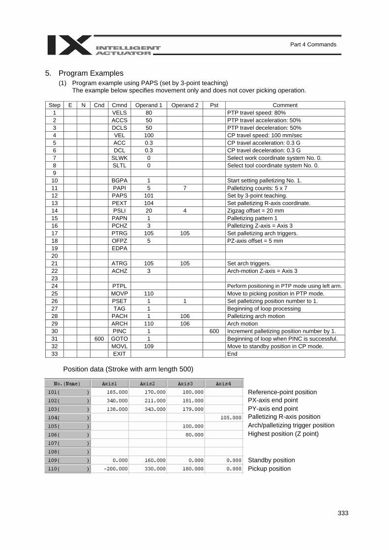
333
Part 4 Commands
5. Program Examples
(1) Program example using PAPS (set by 3-point teaching) The example below specifies movement only and does not cover picking operation.
Step E N Cnd Cmnd Operand 1 Operand 2 Pst Comment
1 VELS 80 PTP travel speed: 80% 2 ACCS 50 PTP travel acceleration: 50% 3 DCLS 50 PTP travel deceleration: 50% 4 VEL 100 CP travel speed: 100 mm/sec 5 ACC 0.3 CP travel acceleration: 0.3 G 6 DCL 0.3 CP travel deceleration: 0.3 G 7 SLWK 0 Select work coordinate system No. 0. 8 SLTL 0 Select tool coordinate system No. 0. 9 10 BGPA 1 Start setting palletizing No. 1. 11 PAPI 5 7 Palletizing counts: 5 x 7 12 PAPS 101 Set by 3-point teaching. 13 PEXT 104 Set palletizing R-axis coordinate. 14 PSLI 20 4 Zigzag offset = 20 mm 15 PAPN 1 Palletizing pattern 1 16 PCHZ 3 Palletizing Z-axis = Axis 3 17 PTRG 105 105 Set palletizing arch triggers. 18 OFPZ 5 PZ-axis offset = 5 mm 19 EDPA 20 21 ATRG 105 105 Set arch triggers. 22 ACHZ 3 Arch-motion Z-axis = Axis 3 23 24 PTPL Perform positioning in PTP mode using left arm.25 MOVP 110 Move to picking position in PTP mode. 26 PSET 1 1 Set palletizing position number to 1. 27 TAG 1 Beginning of loop processing 28 PACH 1 106 Palletizing arch motion 29 ARCH 110 106 Arch motion 30 PINC 1 600 Increment palletizing position number by 1. 31 600 GOTO 1 Beginning of loop when PINC is successful. 32 MOVL 109 Move to standby position in CP mode. 33 EXIT End
Position data (Stroke with arm length 500)
Reference-point position PX-axis end point PY-axis end point Palletizing R-axis position Arch/palletizing trigger position Highest position (Z point) Standby position Pickup position
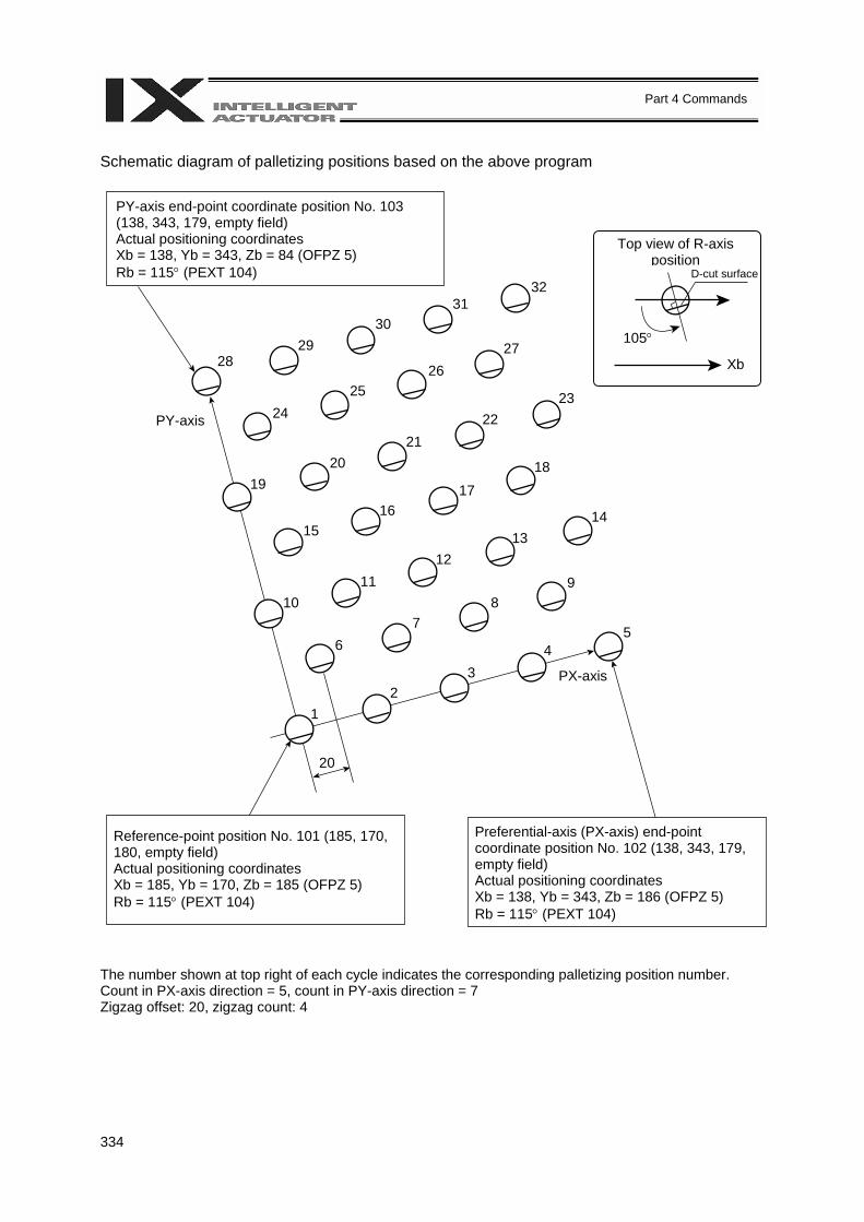
334
Part 4 Commands
Schematic diagram of palletizing positions based on the above program The number shown at top right of each cycle indicates the corresponding palletizing position number. Count in PX-axis direction = 5, count in PY-axis direction = 7 Zigzag offset: 20, zigzag count: 4
PY-axis end-point coordinate position No. 103 (138, 343, 179, empty field) Actual positioning coordinates Xb = 138, Yb = 343, Zb = 84 (OFPZ 5) Rb = 115° (PEXT 104)
Top view of R-axis position
D-cut surface
105°
Xb
PY-axis
PX-axis
Reference-point position No. 101 (185, 170, 180, empty field) Actual positioning coordinates Xb = 185, Yb = 170, Zb = 185 (OFPZ 5) Rb = 115° (PEXT 104)
Preferential-axis (PX-axis) end-point coordinate position No. 102 (138, 343, 179, empty field) Actual positioning coordinates Xb = 138, Yb = 343, Zb = 186 (OFPZ 5) Rb = 115° (PEXT 104)
28 29
30 31
32
24 25
26 27
19 20
21 22
23
15 16
17 18
10 11
12 13
14
6 7
8 9
1 2
3 4
5
20

335
Part 4 Commands
(2) Program example using PASE, PAPT and PAST
The example below specifies movement only and does not cover picking operation.
Step E N Cnd Cmnd Operand 1 Operand 2 Pst Comment 1 VELS 80 PTP travel speed: 80% 2 ACCS 50 PTP travel acceleration: 50% 3 DCLS 50 PTP travel deceleration: 50% 4 VEL 100 CP travel speed: 100 mm/sec 5 ACC 0.3 CP travel acceleration: 0.3 G 6 DCL 0.3 CP travel deceleration: 0.3 G 7 SLWK 0 Select work coordinate system No. 0. 8 SLTL 0 Select tool coordinate system No. 0. 9 10 BGPA 1 Start setting palletizing No. 1. 11 PAST 201 Set reference-point data. 12 PASE 1 2 PX-axis = X-axis, PY-axis = Y-axis 13 PAPT 40 30 Pitch PX: 40, PY: 30 14 PAPI 5 7 Palletizing counts: 5 x 7 15 PSLI 20 4 Zigzag offset = 20 mm, count = 4 16 PEXT 202 Set palletizing R-axis coordinate. 17 PCHZ 3 Palletizing Z-axis = Axis 3 18 PTRG 203 203 Set palletizing arch triggers. 19 OFPZ 5 PZ-axis offset = 5 mm 20 EDPA 21 22 ATRG 203 203 Set arch triggers. 23 ACHZ 3 Arch-motion Z-axis = Axis 3 24 25 PTPL Perform positioning in PTP mode using left arm. 26 MOVP 208 Move to picking position in PTP mode. 27 PSET 1 1 Set palletizing position number to 1. 28 TAG 1 Beginning of loop processing 29 PACH 1 204 Palletizing arch motion 30 ARCH 208 204 Arch motion 31 PINC 1 600 Increment palletizing position number by 1. 32 600 GOTO 1 Beginning of loop when PINC is successful. 33 MOVL 207 Move to standby position in CP mode. 34 EXIT End
Position data (Stroke with arm length 500)
Reference-point position Palletizing R-axis position Arch/palletizing trigger position Highest position (Z point) Standby position Pickup position
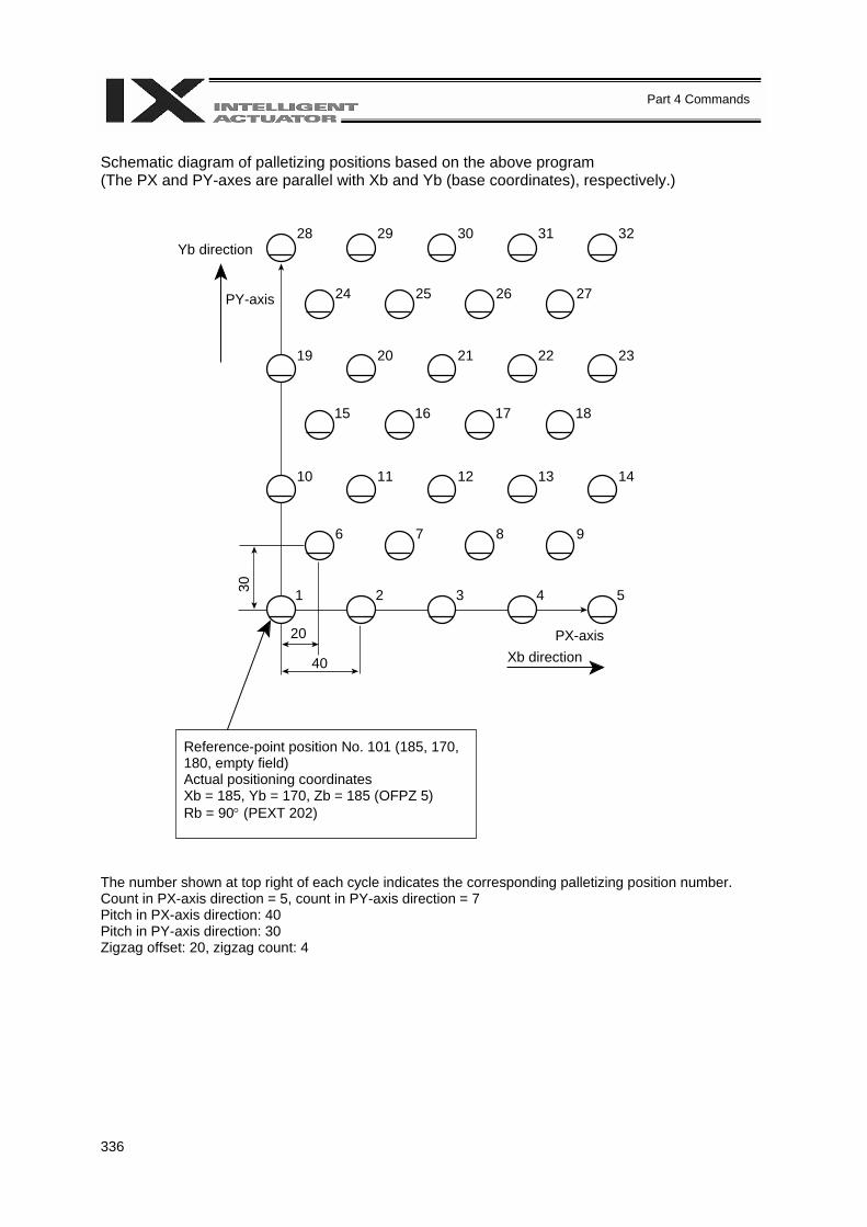
336
Part 4 Commands
Schematic diagram of palletizing positions based on the above program (The PX and PY-axes are parallel with Xb and Yb (base coordinates), respectively.) The number shown at top right of each cycle indicates the corresponding palletizing position number. Count in PX-axis direction = 5, count in PY-axis direction = 7 Pitch in PX-axis direction: 40 Pitch in PY-axis direction: 30 Zigzag offset: 20, zigzag count: 4
PY-axis
PX-axis
Reference-point position No. 101 (185, 170, 180, empty field) Actual positioning coordinates Xb = 185, Yb = 170, Zb = 185 (OFPZ 5) Rb = 90° (PEXT 202)
28 29 30 31 32
20
Yb direction
40 Xb direction
30
24 25 26 27
19 20 21 22 23
15 16 17 18
10 11 12 13 14
6 7 8 9
1 2 3 4 5
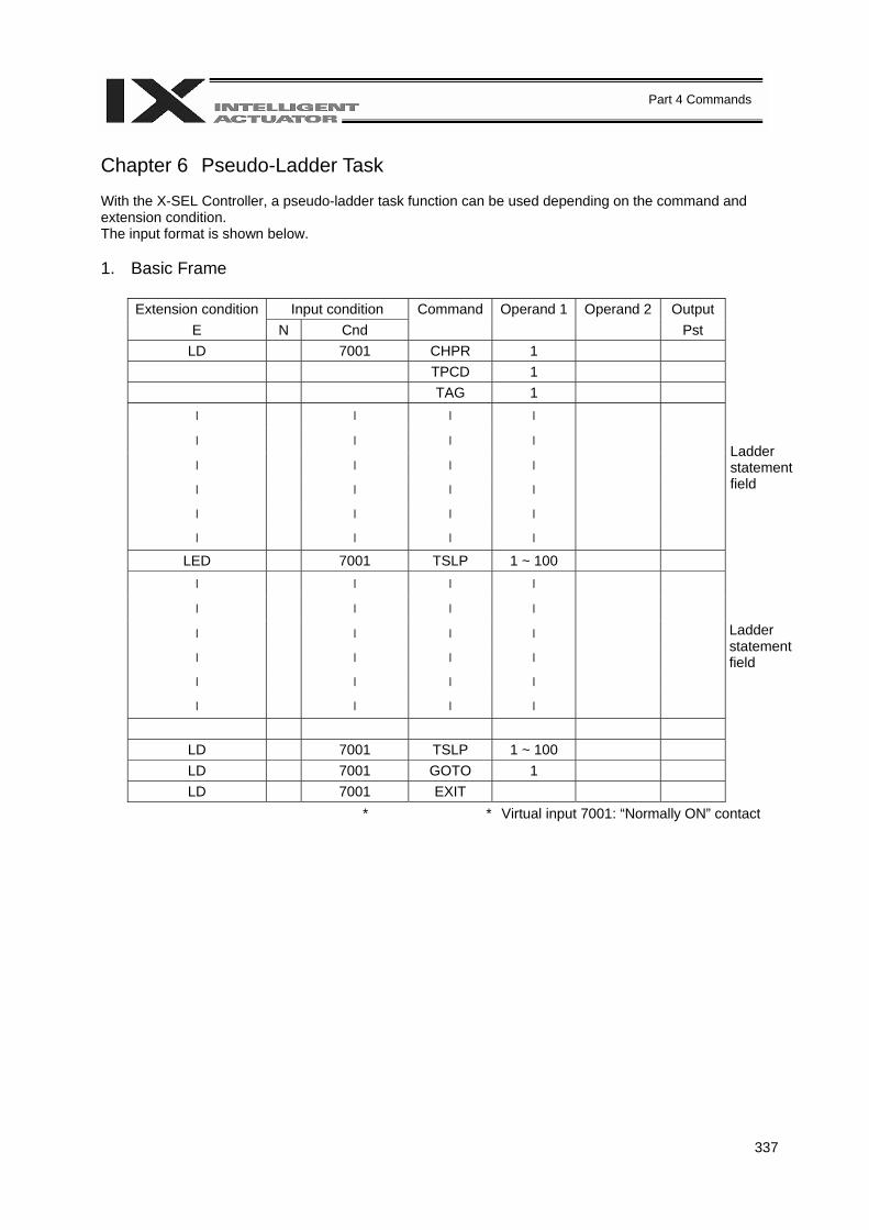
337
Part 4 Commands
Chapter 6 Pseudo-Ladder Task With the X-SEL Controller, a pseudo-ladder task function can be used depending on the command and extension condition. The input format is shown below. 1. Basic Frame
Extension condition Input condition Command Operand 1 Operand 2 Output E N Cnd Pst
LD 7001 CHPR 1 TPCD 1 TAG 1 l l l l
l l l l
l l l l
l l l l
l l l l
l
l l l
LED 7001 TSLP 1 ~ 100 l l l l
l l l l
l l l l
l l l l
l l l l
l
l l l
LD 7001 TSLP 1 ~ 100 LD 7001 GOTO 1 LD 7001 EXIT
* * Virtual input 7001: “Normally ON” contact
Ladder statement field
Ladder statement field
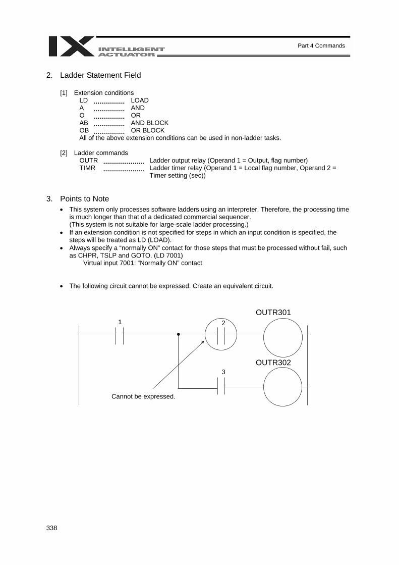
338
Part 4 Commands
2. Ladder Statement Field
[1] Extension conditions LD LOAD A AND O OR AB AND BLOCK OB OR BLOCK All of the above extension conditions can be used in non-ladder tasks.
[2] Ladder commands
OUTR Ladder output relay (Operand 1 = Output, flag number) TIMR Ladder timer relay (Operand 1 = Local flag number, Operand 2 =
Timer setting (sec)) 3. Points to Note
• This system only processes software ladders using an interpreter. Therefore, the processing time is much longer than that of a dedicated commercial sequencer. (This system is not suitable for large-scale ladder processing.)
• If an extension condition is not specified for steps in which an input condition is specified, the steps will be treated as LD (LOAD).
• Always specify a “normally ON” contact for those steps that must be processed without fail, such as CHPR, TSLP and GOTO. (LD 7001)
Virtual input 7001: “Normally ON” contact • The following circuit cannot be expressed. Create an equivalent circuit.
Cannot be expressed.
1 2
3
OUTR301
OUTR302
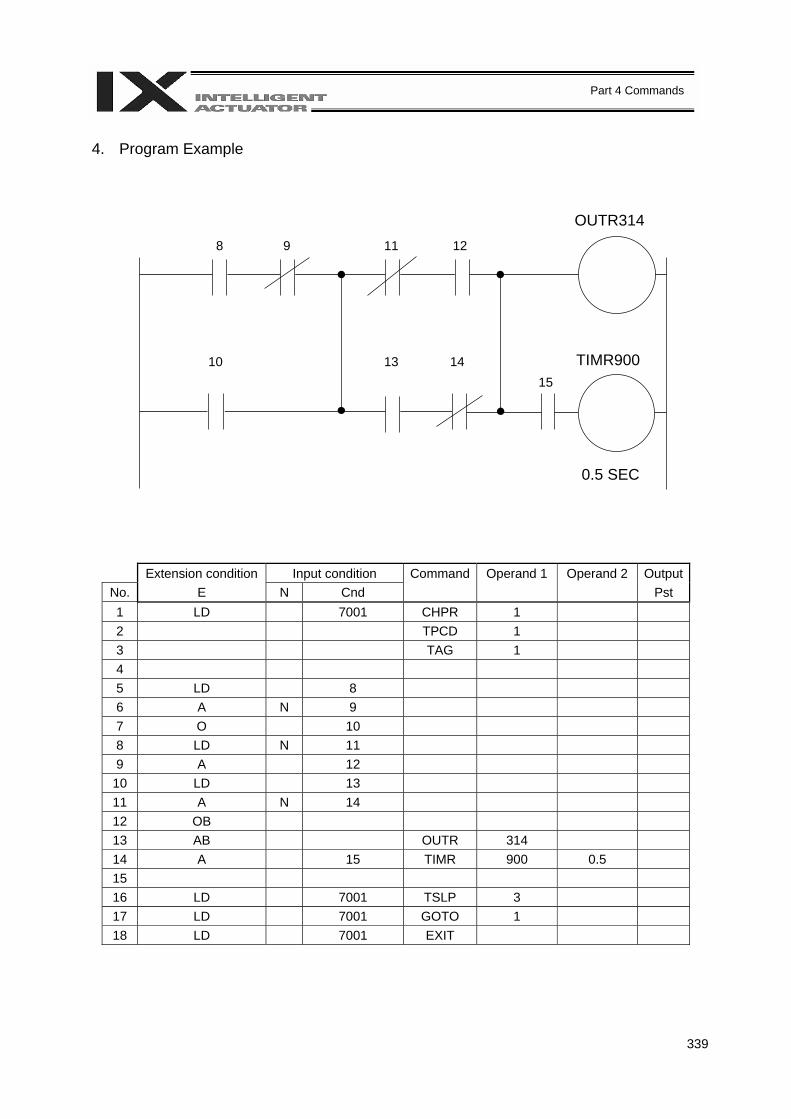
339
Part 4 Commands
4. Program Example
Extension condition Input condition Command Operand 1 Operand 2 OutputNo. E N Cnd Pst 1 LD 7001 CHPR 1 2 TPCD 1 3 TAG 1 4 5 LD 8 6 A N 9 7 O 10 8 LD N 11 9 A 12
10 LD 13 11 A N 14 12 OB 13 AB OUTR 314 14 A 15 TIMR 900 0.5 15 16 LD 7001 TSLP 3 17 LD 7001 GOTO 1 18 LD 7001 EXIT
OUTR314
TIMR900
0.5 SEC
8 9 11 12
10 13 14 15
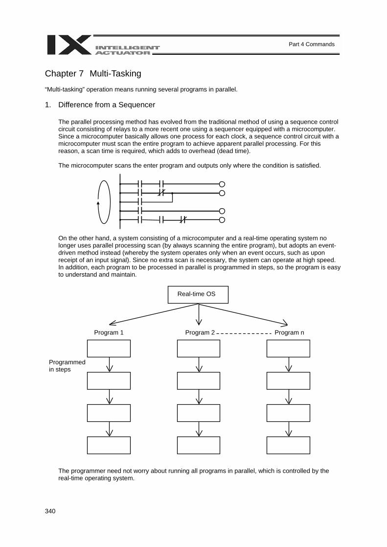
340
Part 4 Commands
Chapter 7 Multi-Tasking “Multi-tasking” operation means running several programs in parallel. 1. Difference from a Sequencer
The parallel processing method has evolved from the traditional method of using a sequence control circuit consisting of relays to a more recent one using a sequencer equipped with a microcomputer. Since a microcomputer basically allows one process for each clock, a sequence control circuit with a microcomputer must scan the entire program to achieve apparent parallel processing. For this reason, a scan time is required, which adds to overhead (dead time). The microcomputer scans the enter program and outputs only where the condition is satisfied.
On the other hand, a system consisting of a microcomputer and a real-time operating system no longer uses parallel processing scan (by always scanning the entire program), but adopts an event-driven method instead (whereby the system operates only when an event occurs, such as upon receipt of an input signal). Since no extra scan is necessary, the system can operate at high speed. In addition, each program to be processed in parallel is programmed in steps, so the program is easy to understand and maintain.
The programmer need not worry about running all programs in parallel, which is controlled by the real-time operating system.
Real-time OS
Program 1 Program 2 Program n
Programmed in steps
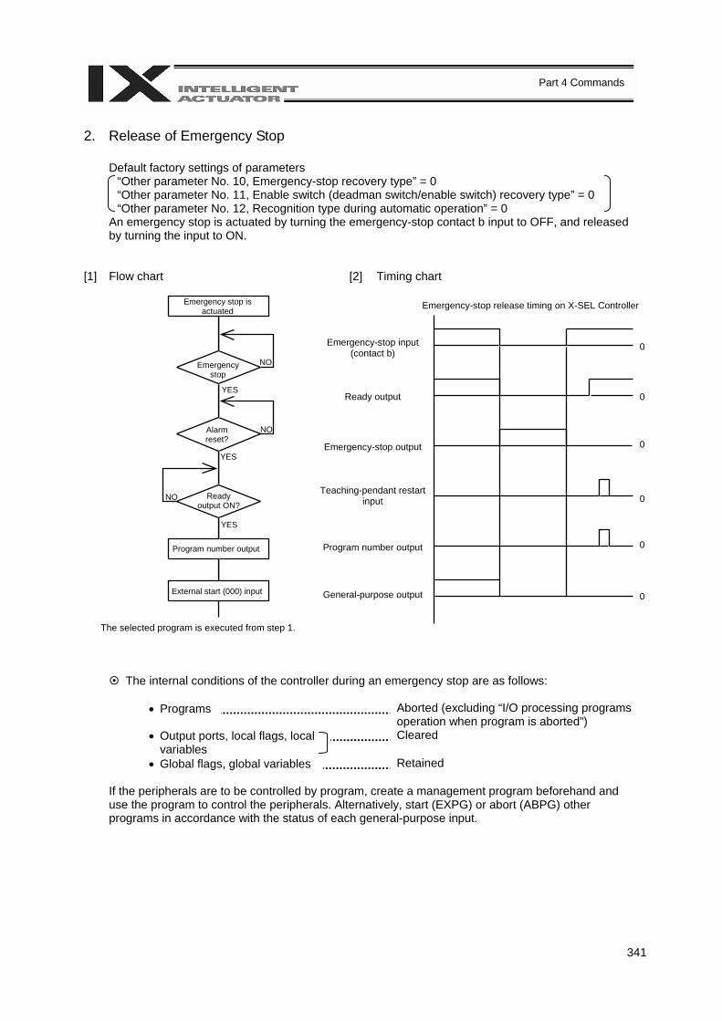
341
Part 4 Commands
2. Release of Emergency Stop
Default factory settings of parameters “Other parameter No. 10, Emergency-stop recovery type” = 0 “Other parameter No. 11, Enable switch (deadman switch/enable switch) recovery type” = 0 “Other parameter No. 12, Recognition type during automatic operation” = 0
An emergency stop is actuated by turning the emergency-stop contact b input to OFF, and released by turning the input to ON.
[1] Flow chart [2] Timing chart
The selected program is executed from step 1.
The internal conditions of the controller during an emergency stop are as follows: • Programs Aborted (excluding “I/O processing programs
operation when program is aborted”) • Output ports, local flags, local
variables Cleared
• Global flags, global variables Retained
If the peripherals are to be controlled by program, create a management program beforehand and use the program to control the peripherals. Alternatively, start (EXPG) or abort (ABPG) other programs in accordance with the status of each general-purpose input.
Emergency stop is actuated
Emergency stop
Alarm reset?
Ready output ON?
Program number output
External start (000) input
NO
NO
NO
YES
YES
YES
Emergency-stop input (contact b)
Ready output
Emergency-stop output
Teaching-pendant restart input
Program number output
General-purpose output
Emergency-stop release timing on X-SEL Controller
0
0 0 0 0 0
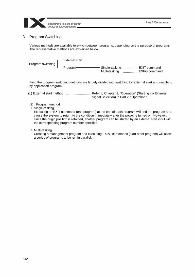
342
Part 4 Commands
3. Program Switching
Various methods are available to switch between programs, depending on the purpose of programs. The representative methods are explained below.
External start Program switching Program Single-tasking EXIT command Multi-tasking EXPG command
First, the program switching methods are largely divided into switching by external start and switching by application program.
(1) External start method Refer to Chapter 1, “Operation” (Starting via External
Signal Selection) in Part 2, “Operation.” (2) Program method
Single-tasking Executing an EXIT command (end program) at the end of each program will end the program and cause the system to return to the condition immediately after the power is turned on. However, since the origin position is retained, another program can be started by an external start input with the corresponding program number specified.
Multi-tasking Creating a management program and executing EXPG commands (start other program) will allow a series of programs to be run in parallel.
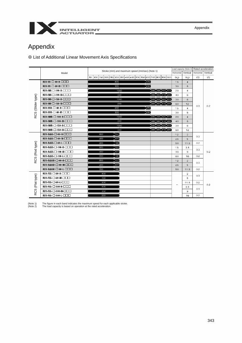
343
Appendix
Appendix
List of Additional Linear Movement Axis Specifications (Note 1) The figure in each band indicates the maximum speed for each applicable stroke. (Note 2) The load capacity is based on operation at the rated acceleration.
Model Stroke (mm) and maximum speed (mm/sec) (Note 1) Load capacity (Note 2) Rated accelerationHorizontal Vertical Horizontal Vertical
RC
S (S
lider
type
) R
CS
(Rod
type
) R
CS
(Fla
t typ
e)
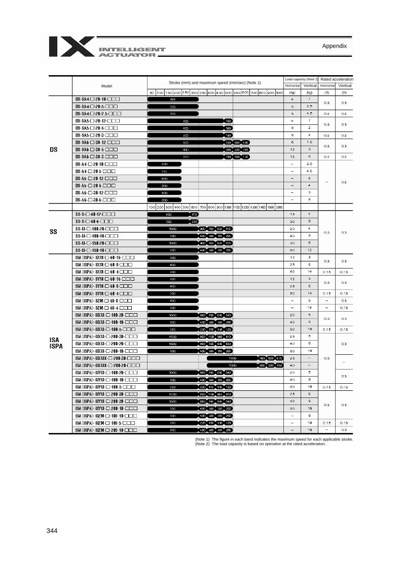
344
Appendix
(Note 1) The figure in each band indicates the maximum speed for each applicable stroke. (Note 2) The load capacity is based on operation at the rated acceleration.
Model Stroke (mm) and maximum speed (mm/sec) (Note 1) Load capacity (Note 2) Rated accelerationHorizontal Vertical Horizontal Vertical
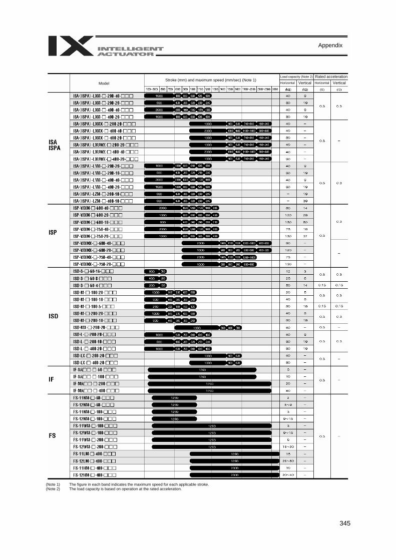
345
Appendix
(Note 1) The figure in each band indicates the maximum speed for each applicable stroke. (Note 2) The load capacity is based on operation at the rated acceleration.
Model Stroke (mm) and maximum speed (mm/sec) (Note 1) Load capacity (Note 2) Rated accelerationHorizontal Vertical Horizontal Vertical
346
Appendix
Battery Backup Function
The X-SEL controller uses the following two types of batteries. • System-memory backup battery
This coin battery is used to back up the position data, SEL program variables, etc., in the controller. Each controller ships with the system-memory backup battery.
• Absolute-encoder backup battery
A separate battery is used to retain the absolute encoder’s rotation data, so that the motor rotation data can be retained/refreshed when the controller power is cut off. A controller specified with an absolute-type actuator is shipped with the absolute-encoder backup battery.
Each battery is explained in details below. 1. System-Memory Backup Battery A coin battery with a holder is installed in the panel on the front side of the controller, in order to retain the various data stored in the SRAM of the X-SEL controller even when the power is cut off. This effectively implements a system memory backup. The data to be backed up by this battery include controller parameters, SEL language variable data (global variables) and position table data. These data can be retained even when the power is cut off. Note, however, that these data are also stored in the flash ROM. If you want your equipment to always start with the defaults (data in the flash ROM) after a power failure or software reset, this battery need not be installed (in such a case, set the applicable controller parameter (other parameter No. 20) so that the system-memory backup battery will not be used). The system-memory backup battery uses a coin battery manufactured by Toshiba. Since the retention characteristics of this battery will vary significantly depending on the storage temperature and operating environment, due caution must be exercised when handling the battery. Although products similar to this battery are readily available in supermarkets, convenience stores, etc., batteries by other manufacturers may offer different retention characteristics. To maintain consistency, use a battery by the same manufacturer whenever possible. <Backup Time> The recommended replacement interval for the system-memory backup battery is one and a half years. This may be a little misleading. It means that if the battery is left at an ambient temperature of 40°C for one and a half years, it will retain the stored data for one and a half years. In normal operating conditions, the battery can retain data for a longer period. As a guide, the battery will last for around three years if the controller is used at an ambient temperature of 40°C with the controller powered up 50% of the time.

347
Appendix
<Battery Replacement> To replace the system-memory backup battery, open the panel window on the front side of the controller and replace the coin battery in the battery holder. It is recommended that the battery be replaced regularly in accordance with the frequency/duration of controller usage. The battery must be replaced as soon as the controller’s battery voltage monitor function generates a battery voltage low alarm. After an alarm is detected, a battery error will occur in approx. 10 days at an ambient temperature of 20°C if the power is supplied to the controller continuously. Once a battery error occurs, the data will be physically lost in approx. four days. If the controller is not operated at all, the above periods should be reduced to 80% at 20°C or to 25% at 40°C. The controller is designed so that the data will not be lost for at least 30 minutes without a battery if the controller is not detecting a battery error. Remember to complete the battery replacement within 30 minutes. To prevent data loss, you can use the PC software to evacuate the data in the SRAM to the flash ROM and then reload the flash ROM data to the SRAM after a new battery is installed. The battery specifications are shown in the table below. List of System-Memory Backup Battery Functions Battery type CR2032 (by Toshiba) Battery voltage 3 V Current capacity 220 mAH Switching voltage at momentary power failure
(Typical) 2.81 V (2.7 V ~ 2.93 V) System reset detection voltage
Power-source voltage drop at backup
(Typical) 0.3 V
Detection voltage for battery voltage low alarm
(Typical) 2.65 V ± 5%
Detection voltage for battery voltage low error
(Typical) 2.37 V ± 5%
Time after alarm detection until error detection (reference)
10 days at 20°C based on continuous operation; 8 days if the power is not supplied at all. 10 days at 40°C based on continuous operation; 2.5 days if the power is not supplied at all.
Minimum data retention voltage Min 2.0 V (Varies depending on the SRAM characteristics) Time after error detection until data loss (reference)
4 days at 20°C based on continuous operation; 3 days if the power is not supplied at all. 4 days at 40°C based on continuous operation; 1 day if the power is not supplied at all.
Data protection time during battery replacement
30 minutes (Maximum retention time when no battery is installed in the battery holder)
Data is retained by the super capacitor inside the controller.
Temperature 40°C, power ON time 0% 1.5 years Guide on when to replace battery
Temperature 40°C, power ON time 50% 3 years

348
Appendix
2. Absolute-Encoder Backup Battery If the X-SEL controller is to drive an absolute-type actuator, an absolute-encoder backup battery must be installed in the robot or controller. An absolute encoder is designed to retain rotation data and detect rotations using the power supplied from the absolute-encoder backup battery, even when the controller’s control power is not supplied. This allows the controller to resume positioning control immediately after the controller power is restored, without performing home return. <Backup Time> The recommended replacement interval for the absolute-encoder backup battery is two to three years. It means that if the battery is left at an ambient temperature of 40°C (with the power not supplied at all), it will retain the stored data for two to three years. In normal operating conditions, the battery can retain data for a longer period. As a guide, the battery will last for around twice the specified period if the controller is used at an ambient temperature of 40°C where the controller powered up 50% of the time. <Battery Replacement> It is recommended that the battery be replaced regularly in accordance with the frequency/duration of controller usage. The battery must be replaced as soon as the controller’s battery voltage monitor function generates a battery voltage low alarm. After an alarm is detected, a battery error will occur in approx. 10 days at an ambient temperature of 20°C if the power is supplied to the controller continuously. Once a battery error occurs, operations can no longer be performed unless the battery is replaced and an absolute encoder reset is performed. If the controller is not operated at all, the above periods should be reduced to 70% at 20°C or to 60% at 40°C. The controller is designed so that the data will not be lost for at least 15 minutes without a battery if the controller is not detecting a battery error. Remember to complete the battery replacement within 15 minutes. To prevent data loss, you can use the PC software to evacuate the data in the SRAM to the flash ROM and then reload the flash ROM data to the SRAM after a new battery is installed. The absolute-encoder backup battery is replaced differently depending on whether a battery error has generated or not. If an error has not been detected yet, the battery needs to be replaced and the absolute encoder must be reset. If an abnormal absolute-encoder backup battery voltage error has been detected (error No. 914, CA1 or CA2), an absolute encoder reset will be required.
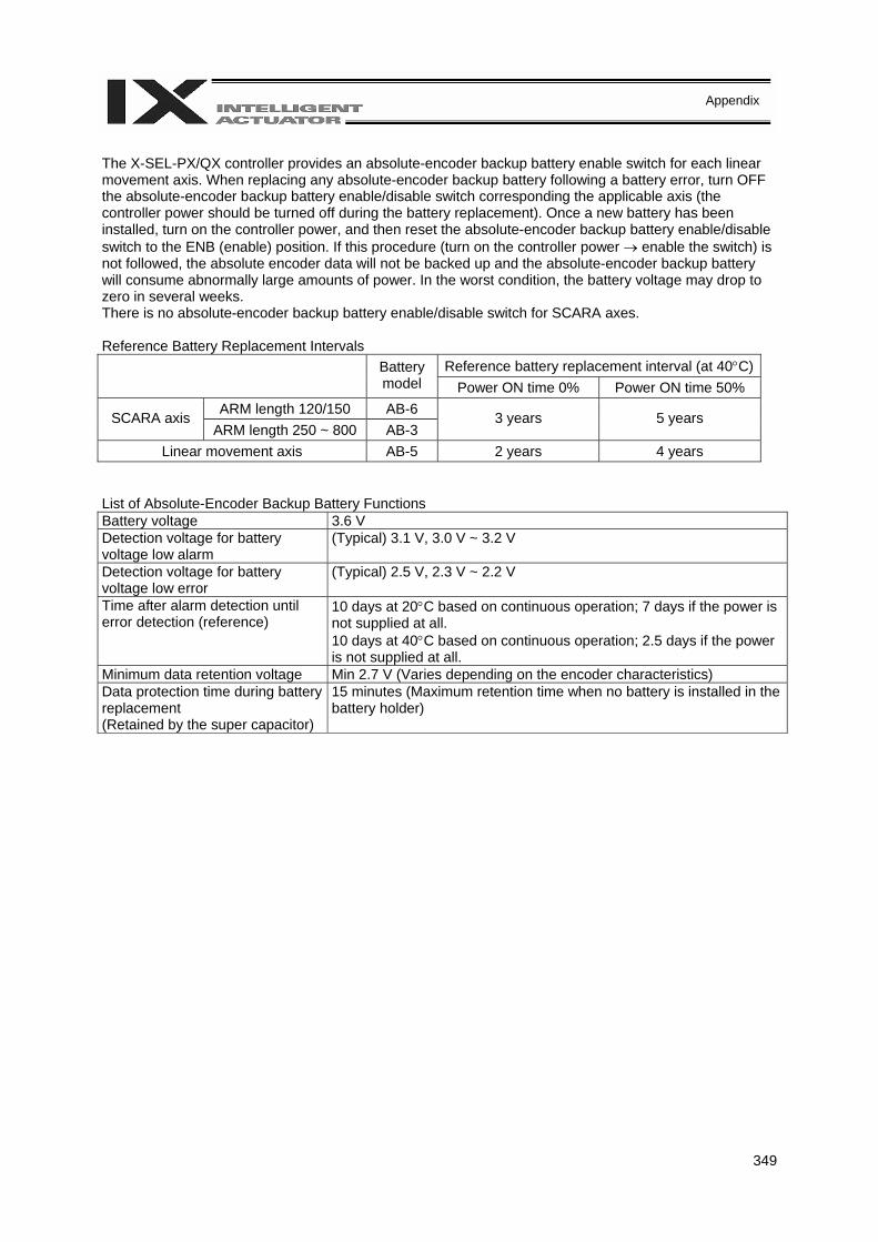
349
Appendix
The X-SEL-PX/QX controller provides an absolute-encoder backup battery enable switch for each linear movement axis. When replacing any absolute-encoder backup battery following a battery error, turn OFF the absolute-encoder backup battery enable/disable switch corresponding the applicable axis (the controller power should be turned off during the battery replacement). Once a new battery has been installed, turn on the controller power, and then reset the absolute-encoder backup battery enable/disable switch to the ENB (enable) position. If this procedure (turn on the controller power → enable the switch) is not followed, the absolute encoder data will not be backed up and the absolute-encoder backup battery will consume abnormally large amounts of power. In the worst condition, the battery voltage may drop to zero in several weeks. There is no absolute-encoder backup battery enable/disable switch for SCARA axes. Reference Battery Replacement Intervals
Reference battery replacement interval (at 40°C) Battery model Power ON time 0% Power ON time 50%
ARM length 120/150 AB-6 SCARA axis ARM length 250 ~ 800 AB-3
3 years 5 years
Linear movement axis AB-5 2 years 4 years List of Absolute-Encoder Backup Battery Functions Battery voltage 3.6 V Detection voltage for battery voltage low alarm
(Typical) 3.1 V, 3.0 V ~ 3.2 V
Detection voltage for battery voltage low error
(Typical) 2.5 V, 2.3 V ~ 2.2 V
Time after alarm detection until error detection (reference)
10 days at 20°C based on continuous operation; 7 days if the power is not supplied at all. 10 days at 40°C based on continuous operation; 2.5 days if the power is not supplied at all.
Minimum data retention voltage Min 2.7 V (Varies depending on the encoder characteristics) Data protection time during battery replacement (Retained by the super capacitor)
15 minutes (Maximum retention time when no battery is installed in the battery holder)
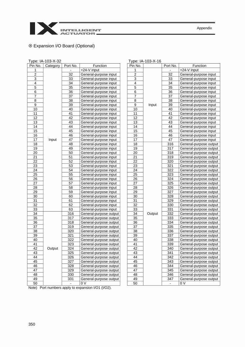
350
Appendix
Expansion I/O Board (Optional)
Type: IA-103-X-32 Type: IA-103-X-16 Pin No. Category Port No. Function Pin No. Port No. Function
1 - +24-V input 1 - +24-V input 2 32 General-purpose input 2 32 General-purpose input 3 33 General-purpose input 3 33 General-purpose input 4 34 General-purpose input 4 34 General-purpose input 5 35 General-purpose input 5 35 General-purpose input 6 36 General-purpose input 6 36 General-purpose input 7 37 General-purpose input 7 37 General-purpose input 8 38 General-purpose input 8 38 General-purpose input 9 39 General-purpose input 9 39 General-purpose input
10 40 General-purpose input 10 40 General-purpose input 11 41 General-purpose input 11 41 General-purpose input 12 42 General-purpose input 12 42 General-purpose input 13 43 General-purpose input 13 43 General-purpose input 14 44 General-purpose input 14 44 General-purpose input 15 45 General-purpose input 15 45 General-purpose input 16 46 General-purpose input 16 46 General-purpose input 17 47 General-purpose input 17
Input
47 General-purpose input 18 48 General-purpose input 18 316 General-purpose output19 49 General-purpose input 19 317 General-purpose output20 50 General-purpose input 20 318 General-purpose output21 51 General-purpose input 21 319 General-purpose output22 52 General-purpose input 22 320 General-purpose output23 53 General-purpose input 23 321 General-purpose output24 54 General-purpose input 24 322 General-purpose output25 55 General-purpose input 25 323 General-purpose output26 56 General-purpose input 26 324 General-purpose output27 57 General-purpose input 27 325 General-purpose output28 58 General-purpose input 28 326 General-purpose output29 59 General-purpose input 29 327 General-purpose output30 60 General-purpose input 30 328 General-purpose output31 61 General-purpose input 31 329 General-purpose output32 62 General-purpose input 32 330 General-purpose output33
Input
63 General-purpose input 33 331 General-purpose output34 316 General-purpose output 34 332 General-purpose output35 317 General-purpose output 35 333 General-purpose output36 318 General-purpose output 36 334 General-purpose output37 319 General-purpose output 37 335 General-purpose output38 320 General-purpose output 38 336 General-purpose output39 321 General-purpose output 39 337 General-purpose output40 322 General-purpose output 40 338 General-purpose output41 323 General-purpose output 41 339 General-purpose output42 324 General-purpose output 42 340 General-purpose output43 325 General-purpose output 43 341 General-purpose output44 326 General-purpose output 44 342 General-purpose output45 327 General-purpose output 45 343 General-purpose output46 328 General-purpose output 46 344 General-purpose output47 329 General-purpose output 47 345 General-purpose output48 330 General-purpose output 48 346 General-purpose output49 331 General-purpose output 49 347 General-purpose output50
Output
- 0 V 50
Output
- 0 V Note) Port numbers apply to expansion I/O1 (I/O2).
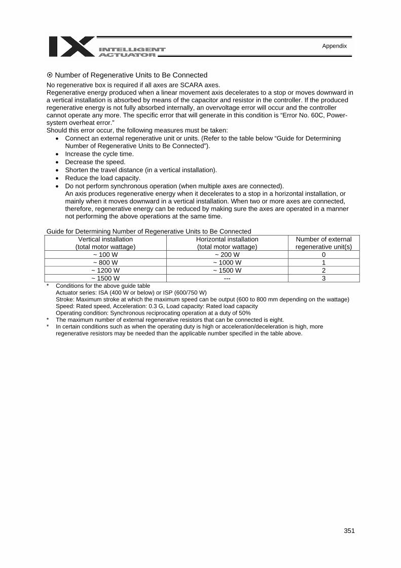
351
Appendix
Number of Regenerative Units to Be Connected
No regenerative box is required if all axes are SCARA axes. Regenerative energy produced when a linear movement axis decelerates to a stop or moves downward in a vertical installation is absorbed by means of the capacitor and resistor in the controller. If the produced regenerative energy is not fully absorbed internally, an overvoltage error will occur and the controller cannot operate any more. The specific error that will generate in this condition is “Error No. 60C, Power-system overheat error.” Should this error occur, the following measures must be taken:
• Connect an external regenerative unit or units. (Refer to the table below “Guide for Determining Number of Regenerative Units to Be Connected”).
• Increase the cycle time. • Decrease the speed. • Shorten the travel distance (in a vertical installation). • Reduce the load capacity. • Do not perform synchronous operation (when multiple axes are connected).
An axis produces regenerative energy when it decelerates to a stop in a horizontal installation, or mainly when it moves downward in a vertical installation. When two or more axes are connected, therefore, regenerative energy can be reduced by making sure the axes are operated in a manner not performing the above operations at the same time.
Guide for Determining Number of Regenerative Units to Be Connected
Vertical installation (total motor wattage)
Horizontal installation (total motor wattage)
Number of external regenerative unit(s)
~ 100 W ~ 200 W 0 ~ 800 W ~ 1000 W 1 ~ 1200 W ~ 1500 W 2 ~ 1500 W --- 3
* Conditions for the above guide table Actuator series: ISA (400 W or below) or ISP (600/750 W) Stroke: Maximum stroke at which the maximum speed can be output (600 to 800 mm depending on the wattage) Speed: Rated speed, Acceleration: 0.3 G, Load capacity: Rated load capacity Operating condition: Synchronous reciprocating operation at a duty of 50%
* The maximum number of external regenerative resistors that can be connected is eight. * In certain conditions such as when the operating duty is high or acceleration/deceleration is high, more
regenerative resistors may be needed than the applicable number specified in the table above.

352
Appendix
List of Parameters
If you have any question regarding changing the parameters, please contact IAI’s Sales Engineering Section. After changing a parameter, record the new and old parameter settings. If you have purchased the PC software, we recommend that you back up the parameters immediately after the controller is delivered and when the system incorporating the controller is started. Since a number of customizing settings use parameters, you should back up the parameters regularly as you back up the programs. To make the new parameters effective, write them to the flash ROM and then execute a software reset or reconnect the power. The lists below are examples of default values displayed on the PC software. The default parameter settings vary depending on the operating condition and actuators used. The input range is based on the maximum and minimum limits of values that can be input using the teaching pendant or PC software. In practice, enter the values defined in the Remarks field. Note: Values other than those defined in the Remarks field, including values inside the applicable input
range, are reserved for future extension. Do not enter values other than those defined in the Remarks field.
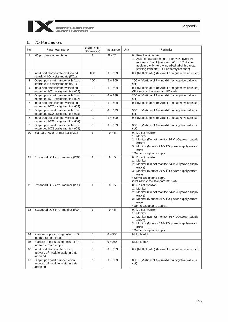
353
Appendix
1. I/O Parameters No. Parameter name Default value
(Reference) Input range Unit Remarks
1 I/O port assignment type 1 0 ~ 20 0: Fixed assignment 1: Automatic assignment (Priority: Network I/F
module > Slot 1 (standard I/O) ~ * Ports are assigned only for the installed adjoining slots, starting from slot 1 = For safety reasons)
2 Input port start number with fixed standard I/O assignments (I/O1)
000 -1 ~ 599 0 + (Multiple of 8) (Invalid if a negative value is set)
3 Output port start number with fixed standard I/O assignments (I/O1)
300 -1 ~ 599 300 + (Multiple of 8) (Invalid if a negative value is set)
4 Input port start number with fixed expanded I/O1 assignments (I/O2)
-1 -1 ~ 599 0 + (Multiple of 8) (Invalid if a negative value is set) (Slot next to the standard I/O slot)
5 Output port start number with fixed expanded I/O1 assignments (I/O2)
-1 -1 ~ 599 300 + (Multiple of 8) (Invalid if a negative value is set)
6 Input port start number with fixed expanded I/O2 assignments (I/O3)
-1 -1 ~ 599 0 + (Multiple of 8) (Invalid if a negative value is set)
7 Output port start number with fixed expanded I/O2 assignments (I/O3)
-1 -1 ~ 599 300 + (Multiple of 8) (Invalid if a negative value is set)
8 Input port start number with fixed expanded I/O3 assignments (I/O4)
-1 -1 ~ 599 0 + (Multiple of 8) (Invalid if a negative value is set)
9 Output port start number with fixed expanded I/O3 assignments (I/O4)
-1 -1 ~ 599 300 + (Multiple of 8) (Invalid if a negative value is set)
10 Standard I/O error monitor (I/O1) 1 0 ~ 5 0: Do not monitor 1: Monitor 2: Monitor (Do not monitor 24-V I/O power-supply
errors) 3: Monitor (Monitor 24-V I/O power-supply errors
only) * Some exceptions apply.
11 Expanded I/O1 error monitor (I/O2) 1 0 ~ 5 0: Do not monitor 1: Monitor 2: Monitor (Do not monitor 24-V I/O power-supply
errors) 3: Monitor (Monitor 24-V I/O power-supply errors
only) * Some exceptions apply. (Slot next to the standard I/O slot)
12 Expanded I/O2 error monitor (I/O3) 1 0 ~ 5 0: Do not monitor 1: Monitor 2: Monitor (Do not monitor 24-V I/O power-supply
errors) 3: Monitor (Monitor 24-V I/O power-supply errors
only) * Some exceptions apply..
13 Expanded I/O3 error monitor (I/O4) 1 0 ~ 5 0: Do not monitor 1: Monitor 2: Monitor (Do not monitor 24-V I/O power-supply
errors) 3: Monitor (Monitor 24-V I/O power-supply errors
only) * Some exceptions apply.
14 Number of ports using network I/F module remote input
0 0 ~ 256 Multiple of 8
15 Number of ports using network I/F module remote output
0 0 ~ 256 Multiple of 8
16 Input port start number when network I/F module assignments are fixed
-1 -1 ~ 599 0 + (Multiple of 8) (Invalid if a negative value is set)
17 Output port start number when network I/F module assignments are fixed
-1 -1 ~ 599 300 + (Multiple of 8) (Invalid if a negative value is set)
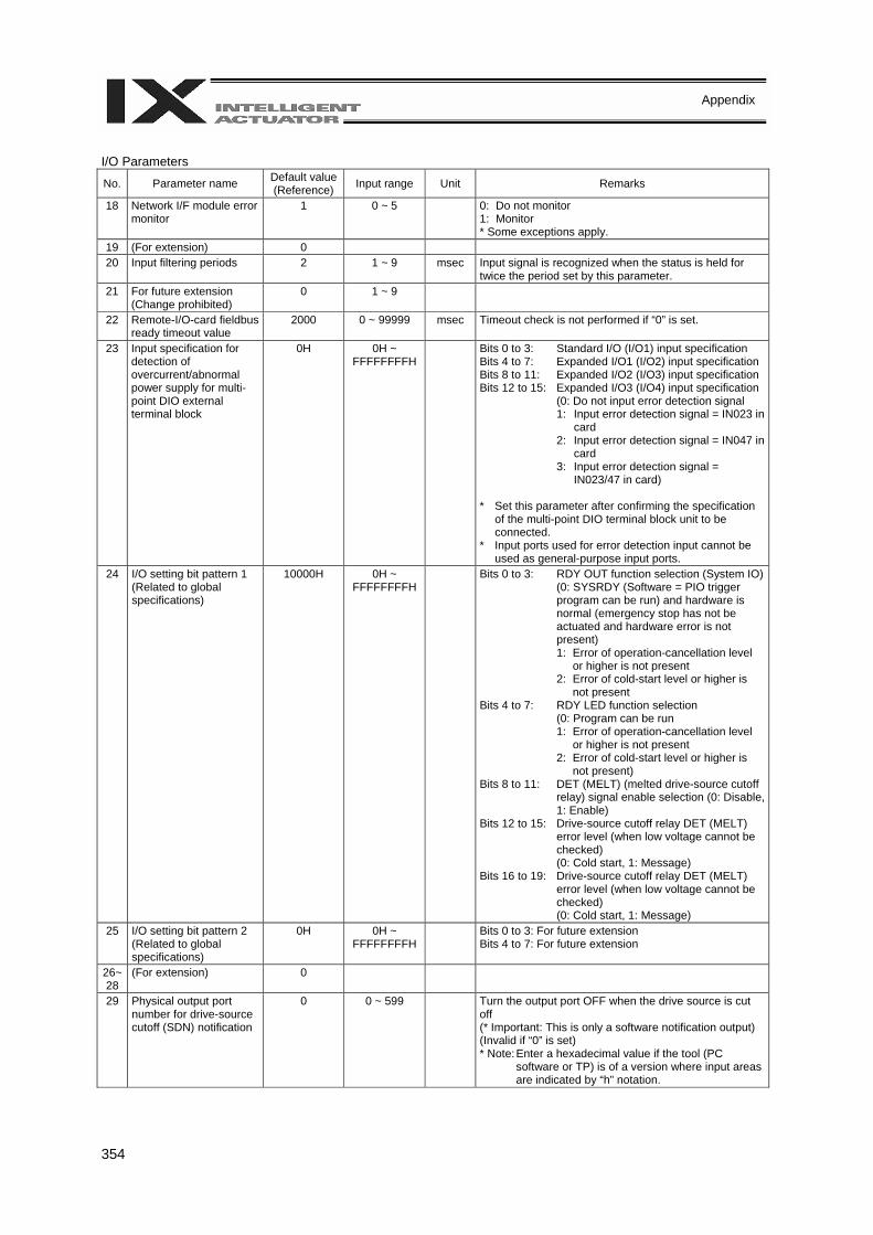
354
Appendix
I/O Parameters
No. Parameter name Default value (Reference) Input range Unit Remarks
18 Network I/F module error monitor
1 0 ~ 5 0: Do not monitor 1: Monitor * Some exceptions apply.
19 (For extension) 0 20 Input filtering periods 2 1 ~ 9 msec Input signal is recognized when the status is held for
twice the period set by this parameter. 21 For future extension
(Change prohibited) 0 1 ~ 9
22 Remote-I/O-card fieldbus ready timeout value
2000 0 ~ 99999 msec Timeout check is not performed if “0” is set.
23 Input specification for detection of overcurrent/abnormal power supply for multi-point DIO external terminal block
0H 0H ~ FFFFFFFFH
Bits 0 to 3: Standard I/O (I/O1) input specification Bits 4 to 7: Expanded I/O1 (I/O2) input specification Bits 8 to 11: Expanded I/O2 (I/O3) input specification Bits 12 to 15: Expanded I/O3 (I/O4) input specification
(0: Do not input error detection signal 1: Input error detection signal = IN023 in
card 2: Input error detection signal = IN047 in
card 3: Input error detection signal =
IN023/47 in card) * Set this parameter after confirming the specification
of the multi-point DIO terminal block unit to be connected.
* Input ports used for error detection input cannot be used as general-purpose input ports.
24 I/O setting bit pattern 1 (Related to global specifications)
10000H 0H ~ FFFFFFFFH
Bits 0 to 3: RDY OUT function selection (System IO)(0: SYSRDY (Software = PIO trigger program can be run) and hardware is normal (emergency stop has not be actuated and hardware error is not present) 1: Error of operation-cancellation level
or higher is not present 2: Error of cold-start level or higher is
not present Bits 4 to 7: RDY LED function selection
(0: Program can be run 1: Error of operation-cancellation level
or higher is not present 2: Error of cold-start level or higher is
not present) Bits 8 to 11: DET (MELT) (melted drive-source cutoff
relay) signal enable selection (0: Disable, 1: Enable)
Bits 12 to 15: Drive-source cutoff relay DET (MELT) error level (when low voltage cannot be checked) (0: Cold start, 1: Message)
Bits 16 to 19: Drive-source cutoff relay DET (MELT) error level (when low voltage cannot be checked) (0: Cold start, 1: Message)
25 I/O setting bit pattern 2 (Related to global specifications)
0H 0H ~ FFFFFFFFH
Bits 0 to 3: For future extension Bits 4 to 7: For future extension
26~28
(For extension) 0
29 Physical output port number for drive-source cutoff (SDN) notification
0 0 ~ 599
Turn the output port OFF when the drive source is cut off (* Important: This is only a software notification output) (Invalid if “0” is set) * Note: Enter a hexadecimal value if the tool (PC
software or TP) is of a version where input areas are indicated by “h” notation.
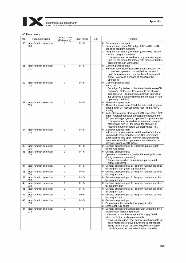
355
Appendix
I/O Parameters No. Parameter name Default value
(Reference) Input range Unit Remarks
30 Input function selection 000
1 0 ~ 5
0: General-purpose input 1: Program start signal (ON edge) (007 to 013: BCD-
specified program number) 2: Program start signal (ON edge) (007 to 013: Binary-
specified program number) * If this parameter is used as a program start signal,
turn ON the signal for at least 100 msec so that the program will start without fail.
31 Input function selection 001
0 0 ~ 5
0: General-purpose input 1: Software reset signal (restart) signal (1 second ON)
* If continued operation is specified as the action upon emergency stop, enable the software reset signal (to provide a means of canceling the operation).
32 Input function selection 002
0 0 ~ 5
0: General-purpose input 1: Servo ON
* ON edge: Equivalent to the all-valid-axis servo ON command, OFF edge: Equivalent to the all-valid-axis servo OFF command (A minimum interval of 1.5 seconds is required) (Must be executed in non-operating condition)
33 Input function selection 003
1 0 ~ 5
0: General-purpose input 1: General-purpose input (Start the auto-start program
upon power-ON reset/software reset in the AUTO mode)
2: Auto-start program start signal (ON edge: Start, OFF edge: Abort all operations/programs (excluding the I/O processing program at operation/program abort)) * If this parameter is used as an auto-start program
start signal, turn ON the signal for at least 100 msec so that the program will start without fail.
34 Input function selection 004
0 0 ~ 5
0: General-purpose input 1: All servo axis soft interlock (OFF level) (Valid for all
commands other than the servo OFF command) (Operation is held upon interlock actuation during automatic operation; operation is terminated upon interlock in non-AUTO mode)
35 Input function selection 005
0 0 ~ 5 0: General-purpose input, 1: Operation-pause reset signal (ON edge)
36 Input function selection 006
0 0 ~ 5
0: General-purpose input 1: Operation-pause reset signal (OFF level) (Valid only
during automatic operation) * Cancel pause when an operation-pause reset
signal is received. 37 Input function selection
007 1 0 ~ 5 0: General-purpose input, 1: Program number specified
for program start (least significant bit) 38 Input function selection
008 1 0 ~ 5 0: General-purpose input, 1: Program number specified
for program start 39 Input function selection
009 1 0 ~ 5 0: General-purpose input, 1: Program number specified
for program start 40 Input function selection
010 1 0 ~ 5 0: General-purpose input, 1: Program number specified
for program start 41 Input function selection
011 1 0 ~ 5 0: General-purpose input, 1: Program number specified
for program start 42 Input function selection
012 1 0 ~ 5 0: General-purpose input, 1: Program number specified
for program start 43 Input function selection
013 1 0 ~ 5
0: General-purpose input 1: Program number specified for program start 2: Error reset (ON edge)
44 Input function selection 014
0 0 ~ 5
0: General-purpose input (Cancel cutoff when the drive-source cutoff factor is removed)
1: Drive-source cutoff reset input (ON edge) (Valid when the factor has been removed) * Drive-source cutoff reset control is not available for
axes whose motor drive power unit is not housed inside this controller or axes whose drive-source cutoff circuit is not controlled by this controller.
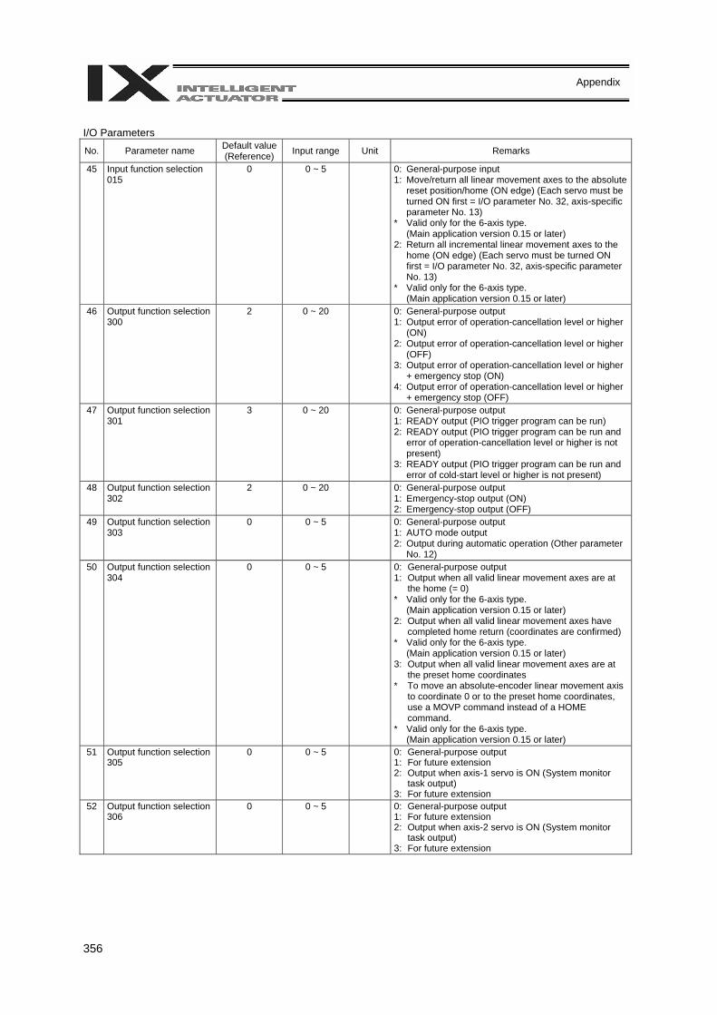
356
Appendix
I/O Parameters
No. Parameter name Default value (Reference) Input range Unit Remarks
45 Input function selection 015
0 0 ~ 5
0: General-purpose input 1: Move/return all linear movement axes to the absolute
reset position/home (ON edge) (Each servo must be turned ON first = I/O parameter No. 32, axis-specific parameter No. 13)
* Valid only for the 6-axis type. (Main application version 0.15 or later)
2: Return all incremental linear movement axes to the home (ON edge) (Each servo must be turned ON first = I/O parameter No. 32, axis-specific parameter No. 13)
* Valid only for the 6-axis type. (Main application version 0.15 or later)
46 Output function selection 300
2 0 ~ 20
0: General-purpose output 1: Output error of operation-cancellation level or higher
(ON) 2: Output error of operation-cancellation level or higher
(OFF) 3: Output error of operation-cancellation level or higher
+ emergency stop (ON) 4: Output error of operation-cancellation level or higher
+ emergency stop (OFF) 47 Output function selection
301 3 0 ~ 20
0: General-purpose output 1: READY output (PIO trigger program can be run) 2: READY output (PIO trigger program can be run and
error of operation-cancellation level or higher is not present)
3: READY output (PIO trigger program can be run and error of cold-start level or higher is not present)
48 Output function selection 302
2 0 ~ 20
0: General-purpose output 1: Emergency-stop output (ON) 2: Emergency-stop output (OFF)
49 Output function selection 303
0 0 ~ 5
0: General-purpose output 1: AUTO mode output 2: Output during automatic operation (Other parameter
No. 12) 50 Output function selection
304 0 0 ~ 5 0: General-purpose output
1: Output when all valid linear movement axes are at the home (= 0)
* Valid only for the 6-axis type. (Main application version 0.15 or later)
2: Output when all valid linear movement axes have completed home return (coordinates are confirmed)
* Valid only for the 6-axis type. (Main application version 0.15 or later)
3: Output when all valid linear movement axes are at the preset home coordinates
* To move an absolute-encoder linear movement axis to coordinate 0 or to the preset home coordinates, use a MOVP command instead of a HOME command.
* Valid only for the 6-axis type. (Main application version 0.15 or later)
51 Output function selection 305
0 0 ~ 5 0: General-purpose output 1: For future extension 2: Output when axis-1 servo is ON (System monitor
task output) 3: For future extension
52 Output function selection 306
0 0 ~ 5 0: General-purpose output 1: For future extension 2: Output when axis-2 servo is ON (System monitor
task output) 3: For future extension
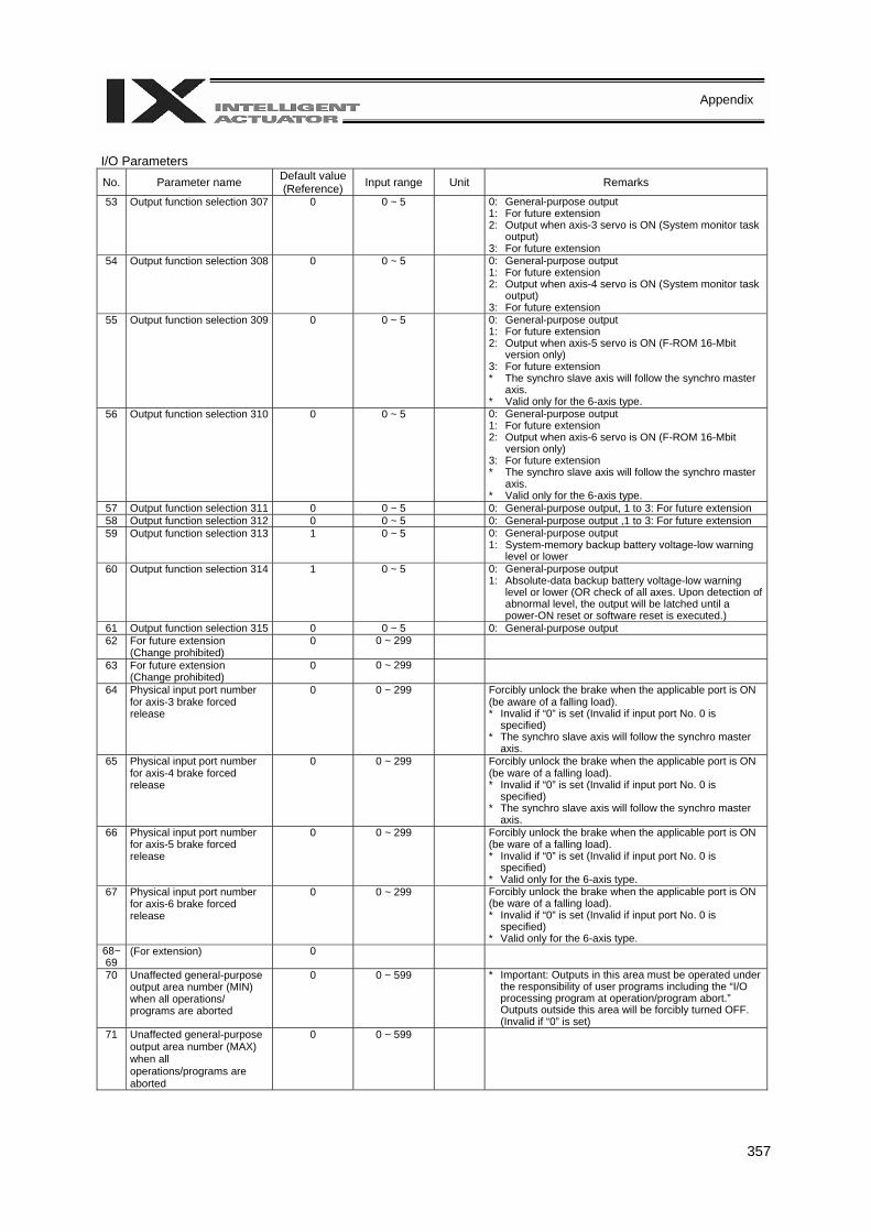
357
Appendix
I/O Parameters No. Parameter name Default value
(Reference) Input range Unit Remarks
53 Output function selection 307 0 0 ~ 5 0: General-purpose output 1: For future extension 2: Output when axis-3 servo is ON (System monitor task
output) 3: For future extension
54 Output function selection 308 0 0 ~ 5 0: General-purpose output 1: For future extension 2: Output when axis-4 servo is ON (System monitor task
output) 3: For future extension
55 Output function selection 309 0 0 ~ 5 0: General-purpose output 1: For future extension 2: Output when axis-5 servo is ON (F-ROM 16-Mbit
version only) 3: For future extension * The synchro slave axis will follow the synchro master
axis. * Valid only for the 6-axis type.
56 Output function selection 310 0 0 ~ 5 0: General-purpose output 1: For future extension 2: Output when axis-6 servo is ON (F-ROM 16-Mbit
version only) 3: For future extension * The synchro slave axis will follow the synchro master
axis. * Valid only for the 6-axis type.
57 Output function selection 311 0 0 ~ 5 0: General-purpose output, 1 to 3: For future extension 58 Output function selection 312 0 0 ~ 5 0: General-purpose output ,1 to 3: For future extension 59 Output function selection 313 1 0 ~ 5 0: General-purpose output
1: System-memory backup battery voltage-low warning level or lower
60 Output function selection 314 1 0 ~ 5 0: General-purpose output 1: Absolute-data backup battery voltage-low warning
level or lower (OR check of all axes. Upon detection of abnormal level, the output will be latched until a power-ON reset or software reset is executed.)
61 Output function selection 315 0 0 ~ 5 0: General-purpose output 62 For future extension
(Change prohibited) 0 0 ~ 299
63 For future extension (Change prohibited)
0 0 ~ 299
64 Physical input port number for axis-3 brake forced release
0 0 ~ 299 Forcibly unlock the brake when the applicable port is ON (be aware of a falling load). * Invalid if “0” is set (Invalid if input port No. 0 is
specified) * The synchro slave axis will follow the synchro master
axis. 65 Physical input port number
for axis-4 brake forced release
0 0 ~ 299 Forcibly unlock the brake when the applicable port is ON (be ware of a falling load). * Invalid if “0” is set (Invalid if input port No. 0 is
specified) * The synchro slave axis will follow the synchro master
axis. 66 Physical input port number
for axis-5 brake forced release
0 0 ~ 299 Forcibly unlock the brake when the applicable port is ON (be ware of a falling load). * Invalid if “0” is set (Invalid if input port No. 0 is
specified) * Valid only for the 6-axis type.
67 Physical input port number for axis-6 brake forced release
0 0 ~ 299 Forcibly unlock the brake when the applicable port is ON (be ware of a falling load). * Invalid if “0” is set (Invalid if input port No. 0 is
specified) * Valid only for the 6-axis type.
68~69
(For extension) 0
70 Unaffected general-purpose output area number (MIN) when all operations/ programs are aborted
0 0 ~ 599 * Important: Outputs in this area must be operated under the responsibility of user programs including the “I/O processing program at operation/program abort.” Outputs outside this area will be forcibly turned OFF. (Invalid if “0” is set)
71 Unaffected general-purpose output area number (MAX) when all operations/programs are aborted
0 0 ~ 599

358
Appendix
I/O Parameters
No. Parameter name Default value (Reference) Input range Unit Remarks
72 Unaffected general-purpose output area number (MIN) when all operations are paused (servo-axis soft interlock + output-port soft interlock)
300 0 ~ 599 * Important: Outputs in this area must be operated (including recovery) under the responsibility of user programs including the “I/O processing program at all operations pause.” Outputs outside this area will be forcibly turned OFF, reflecting/holding the results of operations performed while all operation pause is effective (only during automatic operation). (Invalid if “0” is set)
73 Unaffected general-purpose output area number (MAX) when all operations are paused (servo-axis soft interlock + output-port soft interlock)
599 0 ~ 599
74 Number of TP user output ports used (hand, etc.)
0 0 ~ 8 Referenced by TP. (Invalid if “0” is set)
75 TP user output port start number (hand, etc.)
0 0 ~ 599 Referenced by TP.
76 AUTO-mode physical output port number
0 0 ~ 599 (Invalid if “0” is set)
77 Input port number for acceptance permission of PC/TP servo movement command
0 0 ~ 299 * Important: Invalid after operation has started. (Invalid if “0” is set)
78 Input target axis pattern for acceptance permission of PC/TP servo movement command
0 0B ~ 11111111B
79 Input port number for remote mode control
0 0 ~ 299 The system mode is MANU when the specified DI is ON or the AUTO/MANU switch is set to MANU. (Invalid if “0” is set) * Debug filter is invalid for remote-mode control input ports.
80 (PC/TP SIO usage) 1 1 ~ 1 Switching of DIP switches 81 (PC/TP SIO station code) 153 Reference
only Fixed to 153 (99H).
82 (PC/TP SIO reservation) 0 83 (PC/TP SIO reservation) 0 84 (PC/TP SIO reservation) 0 85 (PC/TP SIO reservation) 0 86 (PC/TP SIO reservation) 0 87 (PC/TP SIO reservation) 0 88 (PC/TP SIO reservation) 0 89 (PC/TP SIO reservation) 0 90 Usage of SIO channel 0
opened to user (AUTO mode)
0 0 ~ 9 0: Open SEL program 1: Open SEL program (Connect PC/TP when both
devices are closed = Used exclusively by the manufacturer)
2: IAI protocol B (Slave) 91 Station code of SIO
channel 0 opened to user 153 0 ~ 255 Valid only with IAI protocol.
92 Baud rate type of SIO channel 0 opened to user
0 0 ~ 5 0: 9.6 1: 19.2 2: 38.4 3: 57.6 4: 76.8 5: 115.2 kbps
93 Data length of SIO channel 0 opened to user
8 7 ~ 8
94 Stop bit length of SIO channel 0 opened to user
1 1 ~ 2
95 Parity type of SIO channel 0 opened to use
0 0 ~ 2 0: None 1: Odd 2: Even
PC: PC software TP: Teaching pendant
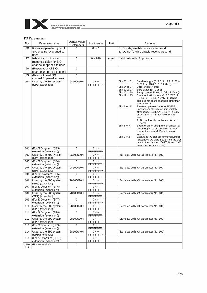
359
Appendix
I/O Parameters No. Parameter name Default value
(Reference) Input range Unit Remarks
96 Receive operation type of SIO channel 0 opened to user
0 0 or 1 0: Forcibly enable receive after send 1: Do not forcibly enable receive at send
97 IAI-protocol minimum response delay for SIO channel 0 opened to user
0 0 ~ 999 msec Valid only with IAI protocol.
98 (Reservation of SIO channel 0 opened to user)
0
99 (Reservation of SIO channel 0 opened to user)
0
100 Used by the SIO system (SP3) (extended)
28100010H 0H ~ FFFFFFFFH
Bits 28 to 31: Baud rate type (0: 9.6, 1: 19.2, 2: 38.4, 3: 57.6, 4: 76.8, 5: 115.2 kbps)
Bits 24 to 27: Data length (7 or 8) Bits 20 to 23: Stop bit length (1 or 2) Bits 16 to 19: Parity type (0: None, 1: Odd, 2: Even) Bits 12 to 15: Communication mode (0: RS232C, 1:
RS422, 2: RS485) * Only “0” can be selected for board channels other than Nos. 1 and 2
Bits 8 to 11: Receive operation type (0: RS485 = Forcibly enable receive immediately after send, RS232C/RS422 = Forcibly enable receive immediately before send 1: Do not forcibly enable receive at
send) Bits 4 to 7: Board channel assignment number (1:
D-sub upper, 2: D-sub lower, 3: Flat connector upper, 4: Flat connector lower)
Bits 0 to 3: Expanded I/O slot assignment number (Expanded I/O slots 1 to 3 from the slot next to the standard IO (I/O1) slot. * “0” means no slots are used)
101 (For SIO system (SP3) extension (extension))
0 0H ~ FFFFFFFFH
102 Used by the SIO system (SP4) (extended)
28100020H 0H ~ FFFFFFFFH
(Same as with I/O parameter No. 100)
103 (For SIO system (SP4) extension (extension))
0 0H ~ FFFFFFFFH
104 Used by the SIO system (SP5) (extended)
28100010H 0H ~ FFFFFFFFH
(Same as with I/O parameter No. 100)
105 (For SIO system (SP5) extension (extension))
0 0H ~ FFFFFFFFH
106 Used by the SIO system (SP6) (extended)
28100020H 0H ~ FFFFFFFFH
(Same as with I/O parameter No. 100)
107 (For SIO system (SP6) extension (extension))
0 0H ~ FFFFFFFFH
108 Used by the SIO system (SP7) (extended)
28100010H 0H ~ FFFFFFFFH
(Same as with I/O parameter No. 100)
109 (For SIO system (SP7) extension (extension))
0 0H ~ FFFFFFFFH
110 Used by the SIO system (SP8) (extended)
28100020H 0H ~ FFFFFFFFH
(Same as with I/O parameter No. 100)
111 (For SIO system (SP8) extension (extension))
0 0H ~ FFFFFFFFH
112 Used by the SIO system (SP9) (extended)
28100030H 0H ~ FFFFFFFFH (Same as with I/O parameter No. 100)
113 (For SIO system (SP9) extension (extension))
0 0H ~ FFFFFFFFH
114 Used by the SIO system (SP10) (extended)
28100040H 0H ~ FFFFFFFFH (Same as with I/O parameter No. 100)
115 (For SIO system (SP10) extension (extension))
0 0H ~ FFFFFFFFH
116~119
(For extension) 0
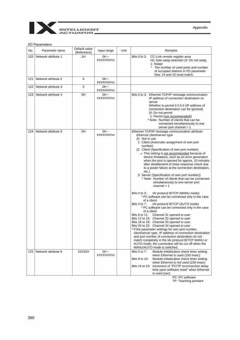
360
Appendix
I/O Parameters
No. Parameter name Default value (Reference) Input range Unit Remarks
120 Network attribute 1 1H 0H ~ FFFFFFFFH
Bits 0 to 3: CC-Link remote register area H/L byte swap selection (0: Do not swap,
1: Swap) * The number of used ports and number
of occupied stations in I/O parameter Nos. 14 and 15 must match.
121 Network attribute 2 0 0H ~ FFFFFFFFH
122 Network attribute 3 0 0H ~ FFFFFFFFH
123 Network attribute 4 0H 0H ~ FFFFFFFFH
Bits 0 to 3: Ethernet TCP/IP message communication IP address of connection destination on
server Whether to permit 0.0.0.0 (IP address of
connection destination can be ignored) (0: Do not permit 1: Permit (not recommended)) * Note: Number of clients that can be
connected simultaneously to one server port channel = 1
124 Network attribute 5 0H 0H ~ FFFFFFFFH
Ethernet TCP/IP message communication attribute Ethernet client/server type (0: Not in use 1: Client (Automatic assignment of own port
number) (2: Client (Specification of own port number) → This setting is not recommended because of
device limitations, such as an error generation when the port is opened for approx. 10 minutes after disablement of close response check due to a power failure at the connection destination, etc.)
3: Server (Specification of own port number)) * Note: Number of clients that can be connected
simultaneously to one server port channel = 1
Bits 0 to 3: IAI protocol B/TCP (MANU mode)
* PC software can be connected only in the case of a client.
Bits 4 to 7: IAI protocol B/TCP (AUTO mode) * PC software can be connected only in the case
of a client. Bits 8 to 11: Channel 31 opened to user Bits 12 to 15: Channel 32 opened to user Bits 16 to 19: Channel 33 opened to user Bits 20 to 23: Channel 34 opened to user * If the parameter settings for own port number,
client/server type, IP address of connection destination and port number of connection destination do not match completely in the IAI protocol B/TCP MANU or AUTO mode, the connection will be cut off when the MANU/AUTO mode is switched.
125 Network attribute 6 31E32H 0H ~ FFFFFFFFH
Bits 0 to 7: Module-initialization check timer setting when Ethernet is used (100 msec)
Bits 8 to 15: Module-initialization check timer setting when Ethernet is not used (100 msec)
Bits 16 to 23: Increment of "PC/TP reconnection delay time upon software reset" when Ethernet is used (sec)
PC: PC software TP: Teaching pendant
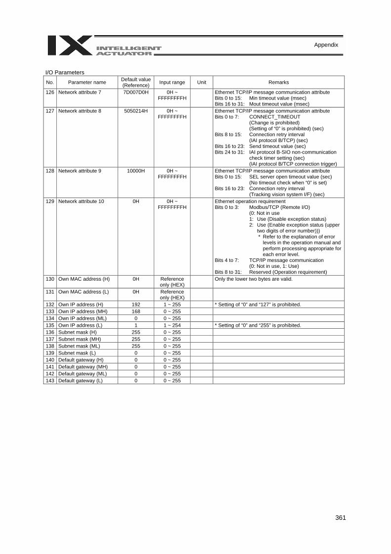
361
Appendix
I/O Parameters
No. Parameter name Default value (Reference) Input range Unit Remarks
126 Network attribute 7 7D007D0H 0H ~ FFFFFFFFH
Ethernet TCP/IP message communication attribute Bits 0 to 15: Min timeout value (msec) Bits 16 to 31: Mout timeout value (msec)
127 Network attribute 8 5050214H 0H ~ FFFFFFFFH
Ethernet TCP/IP message communication attribute Bits 0 to 7: CONNECT_TIMEOUT
(Change is prohibited) (Setting of “0” is prohibited) (sec)
Bits 8 to 15: Connection retry interval (IAI protocol B/TCP) (sec)
Bits 16 to 23: Send timeout value (sec) Bits 24 to 31: IAI protocol B-SIO non-communication
check timer setting (sec) (IAI protocol B/TCP connection trigger)
128 Network attribute 9 10000H 0H ~ FFFFFFFFH
Ethernet TCP/IP message communication attribute Bits 0 to 15: SEL server open timeout value (sec)
(No timeout check when “0” is set) Bits 16 to 23: Connection retry interval
(Tracking vision system I/F) (sec) 129 Network attribute 10 0H 0H ~
FFFFFFFFH
Ethernet operation requirement Bits 0 to 3: Modbus/TCP (Remote I/O)
(0: Not in use 1: Use (Disable exception status) 2: Use (Enable exception status (upper
two digits of error number))) * Refer to the explanation of error
levels in the operation manual and perform processing appropriate for each error level.
Bits 4 to 7: TCP/IP message communication (0: Not in use, 1: Use)
Bits 8 to 31: Reserved (Operation requirement) 130 Own MAC address (H) 0H Reference
only (HEX) Only the lower two bytes are valid.
131 Own MAC address (L) 0H Reference only (HEX)
132 Own IP address (H) 192 1 ~ 255 * Setting of “0” and “127” is prohibited. 133 Own IP address (MH) 168 0 ~ 255 134 Own IP address (ML) 0 0 ~ 255 135 Own IP address (L) 1 1 ~ 254 * Setting of “0” and “255” is prohibited. 136 Subnet mask (H) 255 0 ~ 255 137 Subnet mask (MH) 255 0 ~ 255 138 Subnet mask (ML) 255 0 ~ 255 139 Subnet mask (L) 0 0 ~ 255 140 Default gateway (H) 0 0 ~ 255 141 Default gateway (MH) 0 0 ~ 255 142 Default gateway (ML) 0 0 ~ 255 143 Default gateway (L) 0 0 ~ 255
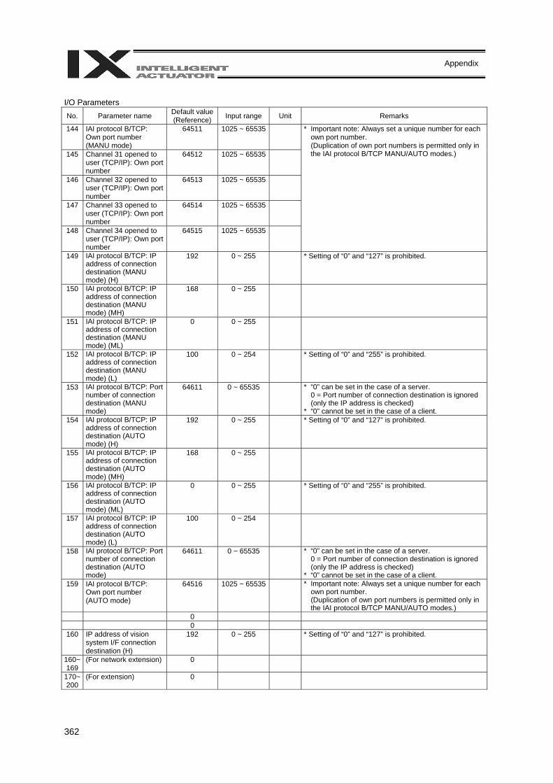
362
Appendix
I/O Parameters No. Parameter name Default value
(Reference) Input range Unit Remarks
144 IAI protocol B/TCP: Own port number (MANU mode)
64511 1025 ~ 65535
145 Channel 31 opened to user (TCP/IP): Own port number
64512 1025 ~ 65535
146 Channel 32 opened to user (TCP/IP): Own port number
64513 1025 ~ 65535
147 Channel 33 opened to user (TCP/IP): Own port number
64514 1025 ~ 65535
148 Channel 34 opened to user (TCP/IP): Own port number
64515 1025 ~ 65535
* Important note: Always set a unique number for each own port number. (Duplication of own port numbers is permitted only in the IAI protocol B/TCP MANU/AUTO modes.)
149 IAI protocol B/TCP: IP address of connection destination (MANU mode) (H)
192 0 ~ 255
* Setting of “0” and “127” is prohibited.
150 IAI protocol B/TCP: IP address of connection destination (MANU mode) (MH)
168 0 ~ 255
151 IAI protocol B/TCP: IP address of connection destination (MANU mode) (ML)
0 0 ~ 255
152 IAI protocol B/TCP: IP address of connection destination (MANU mode) (L)
100 0 ~ 254
* Setting of “0” and “255” is prohibited.
153 IAI protocol B/TCP: Port number of connection destination (MANU mode)
64611 0 ~ 65535
* “0” can be set in the case of a server. 0 = Port number of connection destination is ignored
(only the IP address is checked) * “0” cannot be set in the case of a client.
154 IAI protocol B/TCP: IP address of connection destination (AUTO mode) (H)
192 0 ~ 255
* Setting of “0” and “127” is prohibited.
155 IAI protocol B/TCP: IP address of connection destination (AUTO mode) (MH)
168 0 ~ 255
156 IAI protocol B/TCP: IP address of connection destination (AUTO mode) (ML)
0 0 ~ 255
* Setting of “0” and “255” is prohibited.
157 IAI protocol B/TCP: IP address of connection destination (AUTO mode) (L)
100 0 ~ 254
158 IAI protocol B/TCP: Port number of connection destination (AUTO mode)
64611 0 ~ 65535
* “0” can be set in the case of a server. 0 = Port number of connection destination is ignored
(only the IP address is checked) * “0” cannot be set in the case of a client.
159 IAI protocol B/TCP: Own port number (AUTO mode)
64516 1025 ~ 65535
* Important note: Always set a unique number for each own port number. (Duplication of own port numbers is permitted only in the IAI protocol B/TCP MANU/AUTO modes.)
0 0
160 IP address of vision system I/F connection destination (H)
192 0 ~ 255
* Setting of “0” and “127” is prohibited.
160~169
(For network extension) 0
170~200
(For extension) 0
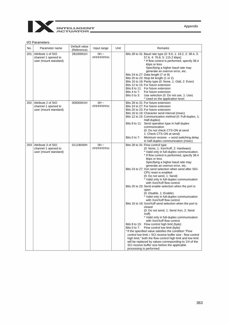
363
Appendix
I/O Parameters
No. Parameter name Default value (Reference) Input range Unit Remarks
201 Attribute 1 of SIO channel 1 opened to user (mount standard)
28100001H 0H ~ FFFFFFFFH
Bits 28 to 31: Baud rate type (0: 9.6, 1: 19.2, 2: 38.4, 3: 57.6, 4: 76.8, 5: 115.2 kbps) * If flow control is performed, specify 38.4
kbps or less Specifying a higher baud rate may generate an overrun error, etc.
Bits 24 to 27: Data length (7 or 8) Bits 20 to 23: Stop bit length (1 or 2) Bits 16 to 19: Parity type (0: None, 1: Odd, 2: Even) Bits 12 to 15: For future extension Bits 8 to 11: For future extension Bits 4 to 7: For future extension Bits 0 to 3: Use selection (0: Do not use, 1: Use)
* Used on the application level. 202 Attribute 2 of SIO
channel 1 opened to user (mount standard)
00000001H 0H ~ FFFFFFFFH
Bits 28 to 31: For future extension Bits 24 to 27: For future extension Bits 20 to 23: For future extension Bits 16 to 19: Character send interval (msec) Bits 12 to 15: Communication method (0: Full-duplex, 1:
Half-duplex) Bits 8 to 11: Send operation type in half-duplex
communication (0: Do not check CTS-ON at send 1: Check CTS-ON at send)
Bits 0 to 7: Minimum receive → send switching delay in half-duplex communication (msec)
203 Attribute 3 of SIO channel 1 opened to user (mount standard)
01118040H 0H ~ FFFFFFFFH
Bits 28 to 31: Flow control type (0: None, 1: Xon/Xoff, 2: Hardware) * Valid only in full-duplex communication. * If flow control is performed, specify 38.4
kbps or less Specifying a higher baud rate may generate an overrun error, etc.
Bits 24 to 27: Xon send selection when send after SIO-CPU reset is enabled (0: Do not send, 1: Send) * Valid only in full-duplex communication
with Xon/Xoff flow control. Bits 20 to 23: Send enable selection when the port is
open (0: Disable, 1: Enable) * Valid only in full-duplex communication
with Xon/Xoff flow control. Bits 16 to 19: Xon/Xoff send selection when the port is
closed (0: Do not send, 1: Send Xon, 2: Send Xoff) * Valid only in full-duplex communication
with Xon/Xoff flow control. Bits 8 to 15: Flow control high limit (byte) Bits 0 to 7: Flow control low limit (byte) * If the specified value satisfies the condition “Flow control low limit ≥ SCI receive buffer size - flow control high limit,” both the flow control high limit and low limit will be replaced by values corresponding to 1/4 of the SCI receive buffer size before the applicable processing is performed.
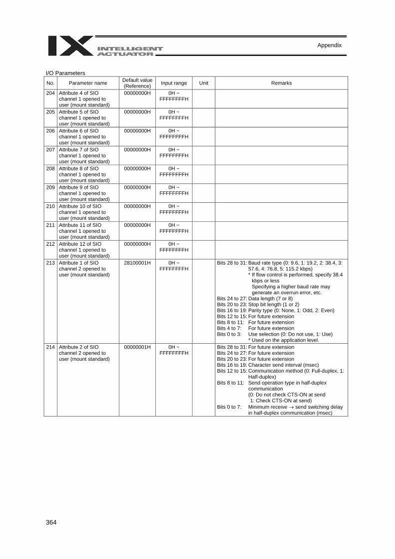
364
Appendix
I/O Parameters
No. Parameter name Default value (Reference) Input range Unit Remarks
204 Attribute 4 of SIO channel 1 opened to user (mount standard)
00000000H 0H ~ FFFFFFFFH
205 Attribute 5 of SIO channel 1 opened to user (mount standard)
00000000H 0H ~ FFFFFFFFH
206 Attribute 6 of SIO channel 1 opened to user (mount standard)
00000000H 0H ~ FFFFFFFFH
207 Attribute 7 of SIO channel 1 opened to user (mount standard)
00000000H 0H ~ FFFFFFFFH
208 Attribute 8 of SIO channel 1 opened to user (mount standard)
00000000H 0H ~ FFFFFFFFH
209 Attribute 9 of SIO channel 1 opened to user (mount standard)
00000000H 0H ~ FFFFFFFFH
210 Attribute 10 of SIO channel 1 opened to user (mount standard)
00000000H 0H ~ FFFFFFFFH
211 Attribute 11 of SIO channel 1 opened to user (mount standard)
00000000H 0H ~ FFFFFFFFH
212 Attribute 12 of SIO channel 1 opened to user (mount standard)
00000000H 0H ~ FFFFFFFFH
213 Attribute 1 of SIO channel 2 opened to user (mount standard)
28100001H 0H ~ FFFFFFFFH
Bits 28 to 31: Baud rate type (0: 9.6, 1: 19.2, 2: 38.4, 3: 57.6, 4: 76.8, 5: 115.2 kbps) * If flow control is performed, specify 38.4
kbps or less Specifying a higher baud rate may generate an overrun error, etc.
Bits 24 to 27: Data length (7 or 8) Bits 20 to 23: Stop bit length (1 or 2) Bits 16 to 19: Parity type (0: None, 1: Odd, 2: Even) Bits 12 to 15: For future extension Bits 8 to 11: For future extension Bits 4 to 7: For future extension Bits 0 to 3: Use selection (0: Do not use, 1: Use)
* Used on the application level. 214 Attribute 2 of SIO
channel 2 opened to user (mount standard)
00000001H 0H ~ FFFFFFFFH
Bits 28 to 31: For future extension Bits 24 to 27: For future extension Bits 20 to 23: For future extension Bits 16 to 19: Character send interval (msec) Bits 12 to 15: Communication method (0: Full-duplex, 1:
Half-duplex) Bits 8 to 11: Send operation type in half-duplex
communication (0: Do not check CTS-ON at send
1: Check CTS-ON at send) Bits 0 to 7: Minimum receive → send switching delay
in half-duplex communication (msec)
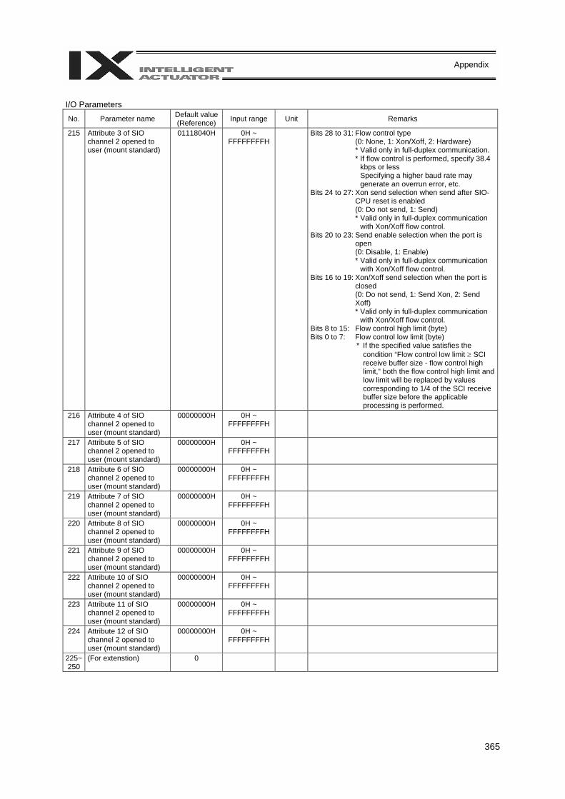
365
Appendix
I/O Parameters
No. Parameter name Default value (Reference) Input range Unit Remarks
215 Attribute 3 of SIO channel 2 opened to user (mount standard)
01118040H 0H ~ FFFFFFFFH
Bits 28 to 31: Flow control type (0: None, 1: Xon/Xoff, 2: Hardware) * Valid only in full-duplex communication. * If flow control is performed, specify 38.4
kbps or less Specifying a higher baud rate may generate an overrun error, etc.
Bits 24 to 27: Xon send selection when send after SIO-CPU reset is enabled (0: Do not send, 1: Send) * Valid only in full-duplex communication
with Xon/Xoff flow control. Bits 20 to 23: Send enable selection when the port is
open (0: Disable, 1: Enable) * Valid only in full-duplex communication
with Xon/Xoff flow control. Bits 16 to 19: Xon/Xoff send selection when the port is
closed (0: Do not send, 1: Send Xon, 2: Send Xoff) * Valid only in full-duplex communication
with Xon/Xoff flow control. Bits 8 to 15: Flow control high limit (byte) Bits 0 to 7: Flow control low limit (byte)
* If the specified value satisfies the condition “Flow control low limit ≥ SCI receive buffer size - flow control high limit,” both the flow control high limit and low limit will be replaced by values corresponding to 1/4 of the SCI receive buffer size before the applicable processing is performed.
216 Attribute 4 of SIO channel 2 opened to user (mount standard)
00000000H 0H ~ FFFFFFFFH
217 Attribute 5 of SIO channel 2 opened to user (mount standard)
00000000H 0H ~ FFFFFFFFH
218 Attribute 6 of SIO channel 2 opened to user (mount standard)
00000000H 0H ~ FFFFFFFFH
219 Attribute 7 of SIO channel 2 opened to user (mount standard)
00000000H 0H ~ FFFFFFFFH
220 Attribute 8 of SIO channel 2 opened to user (mount standard)
00000000H 0H ~ FFFFFFFFH
221 Attribute 9 of SIO channel 2 opened to user (mount standard)
00000000H 0H ~ FFFFFFFFH
222 Attribute 10 of SIO channel 2 opened to user (mount standard)
00000000H 0H ~ FFFFFFFFH
223 Attribute 11 of SIO channel 2 opened to user (mount standard)
00000000H 0H ~ FFFFFFFFH
224 Attribute 12 of SIO channel 2 opened to user (mount standard)
00000000H 0H ~ FFFFFFFFH
225~250
(For extenstion) 0
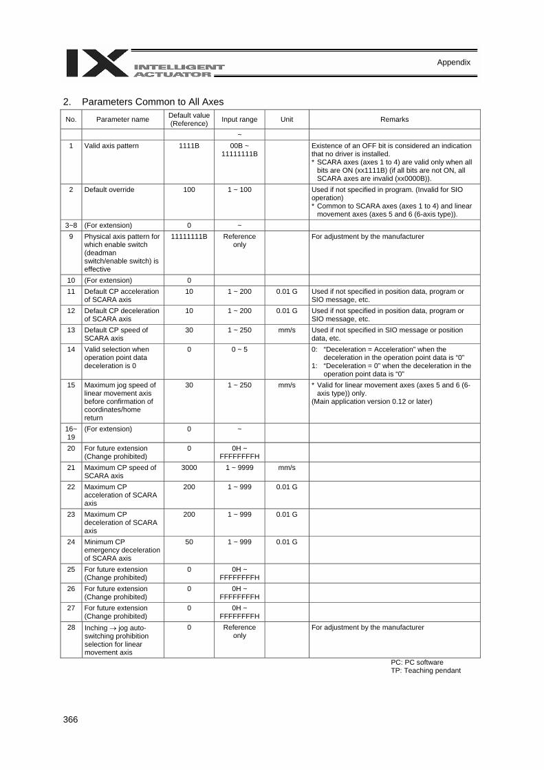
366
Appendix
2. Parameters Common to All Axes
No. Parameter name Default value (Reference) Input range Unit Remarks
~ 1 Valid axis pattern 1111B 00B ~
11111111B Existence of an OFF bit is considered an indication
that no driver is installed. * SCARA axes (axes 1 to 4) are valid only when all
bits are ON (xx1111B) (if all bits are not ON, all SCARA axes are invalid (xx0000B)).
2 Default override 100 1 ~ 100 Used if not specified in program. (Invalid for SIO operation) * Common to SCARA axes (axes 1 to 4) and linear
movement axes (axes 5 and 6 (6-axis type)). 3~8 (For extension) 0 ~
9 Physical axis pattern for which enable switch (deadman switch/enable switch) is effective
11111111B Reference only
For adjustment by the manufacturer
10 (For extension) 0 11 Default CP acceleration
of SCARA axis 10 1 ~ 200 0.01 G Used if not specified in position data, program or
SIO message, etc. 12 Default CP deceleration
of SCARA axis 10 1 ~ 200 0.01 G Used if not specified in position data, program or
SIO message, etc. 13 Default CP speed of
SCARA axis 30 1 ~ 250 mm/s Used if not specified in SIO message or position
data, etc. 14 Valid selection when
operation point data deceleration is 0
0 0 ~ 5 0: “Deceleration = Acceleration” when the deceleration in the operation point data is “0”
1: “Deceleration = 0” when the deceleration in the operation point data is “0”
15 Maximum jog speed of linear movement axis before confirmation of coordinates/home return
30 1 ~ 250 mm/s * Valid for linear movement axes (axes 5 and 6 (6-axis type)) only.
(Main application version 0.12 or later)
16~ 19
(For extension) 0 ~
20 For future extension (Change prohibited)
0 0H ~ FFFFFFFFH
21 Maximum CP speed of SCARA axis
3000 1 ~ 9999 mm/s
22 Maximum CP acceleration of SCARA axis
200 1 ~ 999 0.01 G
23 Maximum CP deceleration of SCARA axis
200 1 ~ 999 0.01 G
24 Minimum CP emergency deceleration of SCARA axis
50 1 ~ 999 0.01 G
25 For future extension (Change prohibited)
0 0H ~ FFFFFFFFH
26 For future extension (Change prohibited)
0 0H ~ FFFFFFFFH
27 For future extension (Change prohibited)
0 0H ~ FFFFFFFFH
28 Inching → jog auto-switching prohibition selection for linear movement axis
0 Reference only
For adjustment by the manufacturer
PC: PC software TP: Teaching pendant
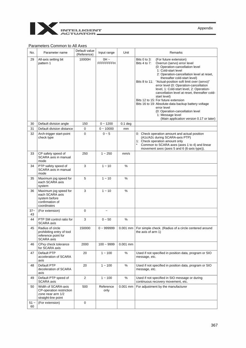
367
Appendix
Parameters Common to All Axes No. Parameter name Default value
(Reference) Input range Unit Remarks
29 All-axis setting bit pattern 1
10000H 0H ~ FFFFFFFFH
Bits 0 to 3: (For future extension) Bits 4 to 7: Overrun (servo) error level
(0: Operation-cancellation level 1: Cold-start level 2: Operation-cancellation level at reset,
thereafter cold-start level) Bits 8 to 11: “Actual-position soft limit over (servo)”
error level (0: Operation-cancellation level, 1: Cold-start level, 2: Operation-cancellation level at reset, thereafter cold-start level)
Bits 12 to 15: For future extension Bits 16 to 19: Absolute-data backup battery voltage
error level (0: Operation-cancellation level 1: Message level
(Main application version 0.17 or later)30 Default division angle 150 0 ~ 1200 0.1 deg 31 Default division distance 0 0 ~ 10000 mm 32 Arch-trigger start-point
check type 0 0 ~ 5 0: Check operation amount and actual position
(A1c/A2c during SCARA-axis PTP) 1: Check operation amount only * Common to SCARA axes (axes 1 to 4) and linear
movement axes (axes 5 and 6 (6-axis type)). 33 CP safety speed of
SCARA axis in manual mode
250 1 ~ 250 mm/s
34 PTP safety speed of SCARA axis in manual mode
3 1 ~ 10 %
35 Maximum jog speed for each SCARA axis system
5 1 ~ 10 %
36 Maximum jog speed for each SCARA axis system before confirmation of coordinates
3 1 ~ 10 %
37~ 43
(For extension) 0 ~
44 PTP SM control ratio for SCARA axis
3 0 ~ 50 %
45 Radius of circle prohibiting entry of tool reference point for SCARA axis
150000 0 ~ 999999 0.001 mm For simple check. (Radius of a circle centered around the axis of arm 1)
46 CPxy check tolerance for SCARA axis
2000 100 ~ 9999 0.001 mm
47 Default PTP acceleration of SCARA axis
20 1 ~ 100 % Used if not specified in position data, program or SIO message, etc.
48 Default PTP deceleration of SCARA axis
20 1 ~ 100 % Used if not specified in position data, program or SIO message, etc.
49 Default PTP speed of SCARA axis
2 1 ~ 100 % Used if not specified in SIO message or during continuous recovery movement, etc.
50 Width of SCARA-axis CP-operation restriction zone near arm 1/2 straight-line point
500 Reference only
0.001 mm For adjustment by the manufacturer
51 ~ 60
(For extension) 0

368
Appendix
Parameters Common to All Axes No. Parameter name Default value
(Reference) Input range Unit Remarks
61 Tracking control 1 001300H 0H ~ FFFFFFFFH
Bits 0 to 3: Tracking system type (0: Do not use system 1: Work detection sensor
(photoelectric sensor) system 2: Vision system (D-E) 3 to 15: (For extension))
Bits 4 to 7: Tracking-target count input type (0: Tracking-encoder connector input
count 1: Internal motor control encoder
count 2: Virtual conveyor encoder count (for
debugging)) Bits 8 to 11: Tracking-encoder axis number (1 or
greater) * If “Tracking-encoder connector
input count” is specified, specify the axis corresponding to the driver/encoder communication line channel No. 2 (or 3) (the setting can be checked in all-axis parameter Nos. 101 and 102) for “Tracking-encoder axis number.” Also, connect the tracking encoder to the pin corresponding to the above driver/encoder communication line channel number (= tracking-encoder channel number) in the connector. [Reference] Specify axis No. 3 (or 4) for the following models: IX-NNN1205/1505, IX-NNN2515/3515, IX-TNN (UNN) 3015/3515, IX-NNN50 //60 , IX-HNN (INN) 5020/6020 Specify axis No. 2 (or 3) for the following models: IX-NNN (HNN/INN) 70 /80 Always specify axis No. 2 for IX-NSN5016/6016 (high-speed type), etc. * These values are provided for
reference purpose only (as of December 22, 2005), and all-axis parameter Nos. 101 and 102 must be checked on the actual machine.
Bits 12 to 15: Tracking-operation acceleration/deceleration control type(0: PS, 1: PS2)
Bits 16 to 19: For extension Bits 20 to 23: Safety-speed enable selection for
tracking operation (operation in conveyor tracking direction) (0: Disable, 1: Enable)
PC: PC software TP: Teaching pendant
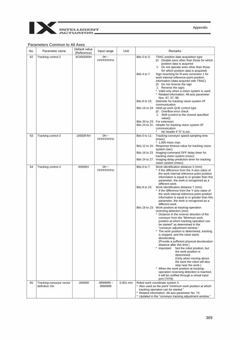
369
Appendix
Parameters Common to All Axes No. Parameter name Default value
(Reference) Input range Unit Remarks
62 Tracking control 2 3C000D00H 0H ~ FFFFFFFFH
Bits 0 to 3: TRAC position data acquisition type (0: Disable axes other than those for which
position data is acquired 1: Do not operate axes other than those
for which position data is acquired) Bits 4 to 7: Sign reversing for R-axis correction 1 for
work internal reference-point position information (data acquired with TRAC) (0: Do not reverse the sign 1: Reverse the sign) * Valid only when a vision system is used. * Related information: All-axis parameter
Nos. 87, 97, 98 Bits 8 to 15: Delimiter for tracking vision system I/F
communication Bits 16 to 19: Held-up work QUE control type
(0: Overflow error check 1: Shift (control to the closest specified
value)) Bits 20 to 23: For extension Bits 24 to 31: Header for tracking vision system I/F
communication * No header if “0” is set.
63 Tracking control 3 10550FAH 0H ~ FFFFFFFFH
Bits 0 to 11: Tracking-conveyor speed sampling time (msec) * 1,000 msec max.
Bits 12 to 15: Response timeout value for tracking vision system (sec)
Bits 16 to 23 Imaging-command OFF delay timer for tracking vision system (msec)
Bits 24 to 27: Imaging-delay prediction timer for tracking vision system (msec)
64 Tracking control 4 A0505H 0H ~ FFFFFFFFH
Bits 0 to 7: Work identification distance X (mm) * If the difference from the X-axis value of
the work internal reference-point position information is equal to or greater than this parameter, the work is recognized as a different work.
Bits 8 to 15: Work identification distance Y (mm) * If the difference from the Y-axis value of
the work internal reference-point position information is equal to or greater than this parameter, the work is recognized as a different work.
Bits 16 to 23: Work position at tracking-operation reversing detection (mm) * Distance in the reverse direction of the
conveyor from the “Minimum work position at which tracking operation can be started” as determined in the “conveyor adjustment window.”
* The work position is determined, tracking is stopped, and the robot starts decelerating. (Provide a sufficient physical deceleration distance after this limit.)
* Important: Not the robot position, but the work position is determined. (Only when moving above the work the robot will also stop near the work.)
* When the work position at tracking-operation reversing detection is reached, it will be notified through a virtual input port (7078).
65 Tracking-conveyor vector definition Xin
-340000 -9999999 ~ 9999999
0.001 mm Robot work coordinate system X * Also used as the point “minimum work position at which
tracking operation can be started.” * Related information: All-axis parameter No. 74 * Updated in the “conveyor tracking adjustment window.”
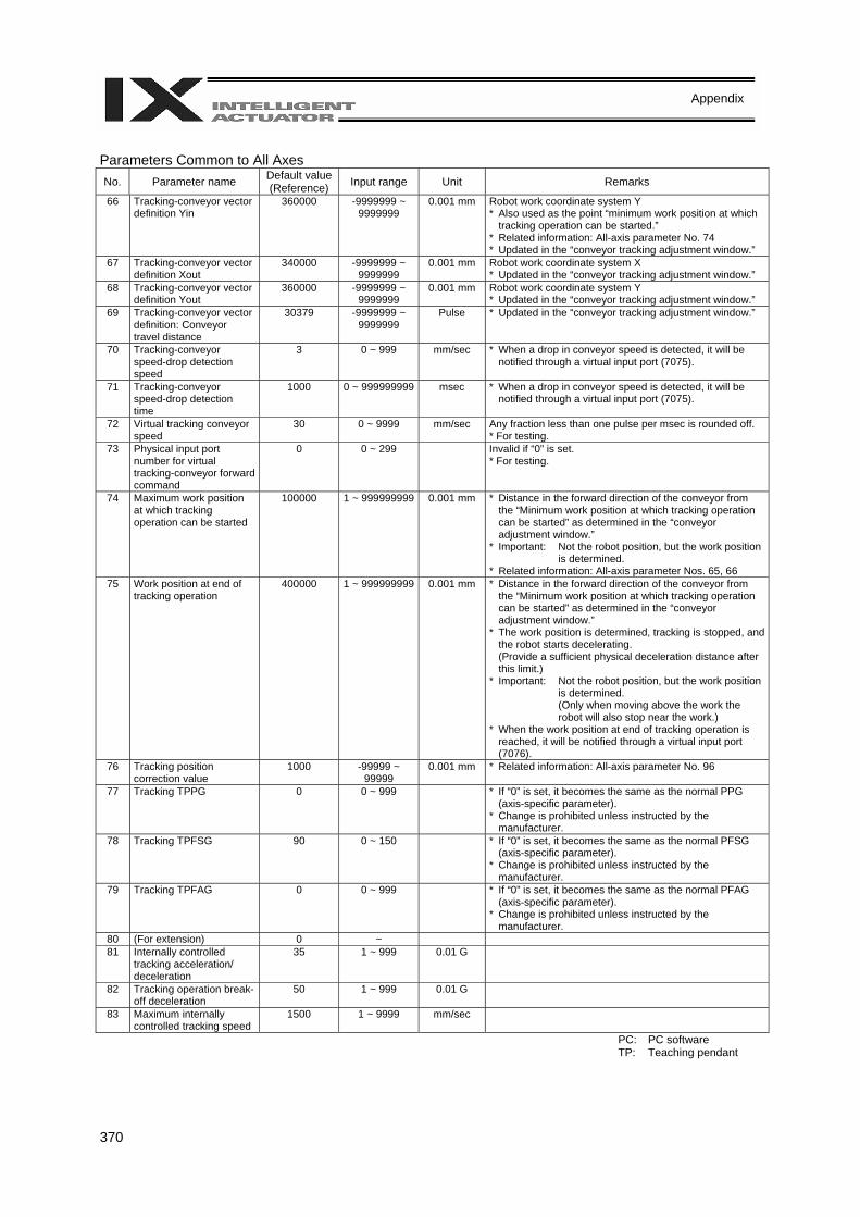
370
Appendix
Parameters Common to All Axes No. Parameter name Default value
(Reference) Input range Unit Remarks
66 Tracking-conveyor vector definition Yin
360000 -9999999 ~ 9999999
0.001 mm Robot work coordinate system Y * Also used as the point “minimum work position at which
tracking operation can be started.” * Related information: All-axis parameter No. 74 * Updated in the “conveyor tracking adjustment window.”
67 Tracking-conveyor vector definition Xout
340000 -9999999 ~ 9999999
0.001 mm Robot work coordinate system X * Updated in the “conveyor tracking adjustment window.”
68 Tracking-conveyor vector definition Yout
360000 -9999999 ~ 9999999
0.001 mm Robot work coordinate system Y * Updated in the “conveyor tracking adjustment window.”
69 Tracking-conveyor vector definition: Conveyor travel distance
30379 -9999999 ~ 9999999
Pulse * Updated in the “conveyor tracking adjustment window.”
70 Tracking-conveyor speed-drop detection speed
3 0 ~ 999 mm/sec * When a drop in conveyor speed is detected, it will be notified through a virtual input port (7075).
71 Tracking-conveyor
speed-drop detection time
1000 0 ~ 999999999 msec * When a drop in conveyor speed is detected, it will be notified through a virtual input port (7075).
72 Virtual tracking conveyor speed
30 0 ~ 9999 mm/sec Any fraction less than one pulse per msec is rounded off. * For testing.
73 Physical input port number for virtual tracking-conveyor forward command
0 0 ~ 299 Invalid if “0” is set. * For testing.
74 Maximum work position at which tracking operation can be started
100000 1 ~ 999999999 0.001 mm * Distance in the forward direction of the conveyor from the “Minimum work position at which tracking operation can be started” as determined in the “conveyor adjustment window.”
* Important: Not the robot position, but the work position is determined.
* Related information: All-axis parameter Nos. 65, 66 75 Work position at end of
tracking operation 400000 1 ~ 999999999 0.001 mm * Distance in the forward direction of the conveyor from
the “Minimum work position at which tracking operation can be started” as determined in the “conveyor adjustment window.”
* The work position is determined, tracking is stopped, and the robot starts decelerating. (Provide a sufficient physical deceleration distance after this limit.)
* Important: Not the robot position, but the work position is determined. (Only when moving above the work the robot will also stop near the work.)
* When the work position at end of tracking operation is reached, it will be notified through a virtual input port (7076).
76 Tracking position correction value
1000 -99999 ~ 99999
0.001 mm * Related information: All-axis parameter No. 96
77 Tracking TPPG 0 0 ~ 999 * If “0” is set, it becomes the same as the normal PPG (axis-specific parameter).
* Change is prohibited unless instructed by the manufacturer.
78 Tracking TPFSG 90 0 ~ 150 * If “0” is set, it becomes the same as the normal PFSG (axis-specific parameter).
* Change is prohibited unless instructed by the manufacturer.
79 Tracking TPFAG 0 0 ~ 999 * If “0” is set, it becomes the same as the normal PFAG (axis-specific parameter).
* Change is prohibited unless instructed by the manufacturer.
80 (For extension) 0 ~ 81 Internally controlled
tracking acceleration/ deceleration
35 1 ~ 999 0.01 G
82 Tracking operation break-off deceleration
50 1 ~ 999 0.01 G
83 Maximum internally controlled tracking speed
1500 1 ~ 9999 mm/sec
PC: PC software TP: Teaching pendant
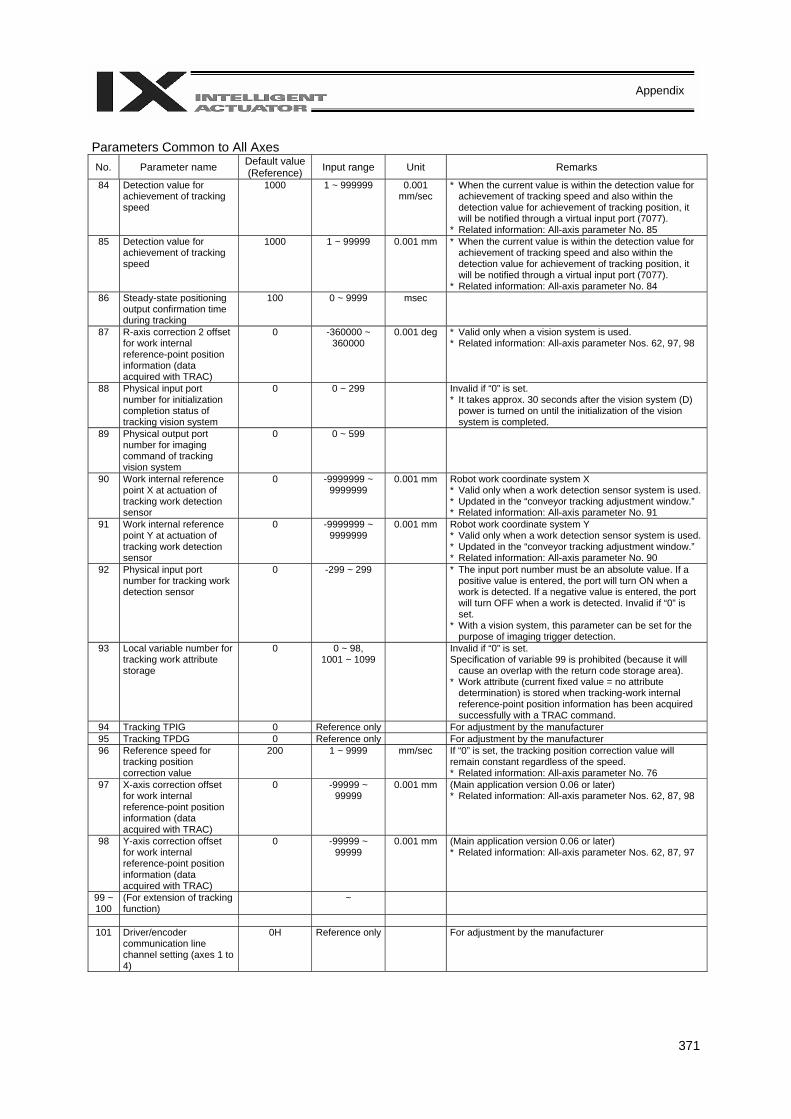
371
Appendix
Parameters Common to All Axes No. Parameter name Default value
(Reference) Input range Unit Remarks
84 Detection value for achievement of tracking speed
1000 1 ~ 999999 0.001 mm/sec
* When the current value is within the detection value for achievement of tracking speed and also within the detection value for achievement of tracking position, it will be notified through a virtual input port (7077).
* Related information: All-axis parameter No. 85 85 Detection value for
achievement of tracking speed
1000 1 ~ 99999 0.001 mm * When the current value is within the detection value for achievement of tracking speed and also within the detection value for achievement of tracking position, it will be notified through a virtual input port (7077).
* Related information: All-axis parameter No. 84 86 Steady-state positioning
output confirmation time during tracking
100 0 ~ 9999 msec
87 R-axis correction 2 offset for work internal reference-point position information (data acquired with TRAC)
0 -360000 ~ 360000
0.001 deg * Valid only when a vision system is used. * Related information: All-axis parameter Nos. 62, 97, 98
88 Physical input port number for initialization completion status of tracking vision system
0 0 ~ 299 Invalid if “0” is set. * It takes approx. 30 seconds after the vision system (D)
power is turned on until the initialization of the vision system is completed.
89 Physical output port number for imaging command of tracking vision system
0 0 ~ 599
90 Work internal reference point X at actuation of tracking work detection sensor
0 -9999999 ~ 9999999
0.001 mm Robot work coordinate system X * Valid only when a work detection sensor system is used. * Updated in the “conveyor tracking adjustment window.” * Related information: All-axis parameter No. 91
91 Work internal reference point Y at actuation of tracking work detection sensor
0 -9999999 ~ 9999999
0.001 mm Robot work coordinate system Y * Valid only when a work detection sensor system is used. * Updated in the “conveyor tracking adjustment window.” * Related information: All-axis parameter No. 90
92 Physical input port number for tracking work detection sensor
0 -299 ~ 299 * The input port number must be an absolute value. If a positive value is entered, the port will turn ON when a work is detected. If a negative value is entered, the port will turn OFF when a work is detected. Invalid if “0” is set.
* With a vision system, this parameter can be set for the purpose of imaging trigger detection.
93 Local variable number for tracking work attribute storage
0 0 ~ 98, 1001 ~ 1099
Invalid if “0” is set. Specification of variable 99 is prohibited (because it will
cause an overlap with the return code storage area). * Work attribute (current fixed value = no attribute
determination) is stored when tracking-work internal reference-point position information has been acquired successfully with a TRAC command.
94 Tracking TPIG 0 Reference only For adjustment by the manufacturer 95 Tracking TPDG 0 Reference only For adjustment by the manufacturer 96 Reference speed for
tracking position correction value
200 1 ~ 9999 mm/sec If “0” is set, the tracking position correction value will remain constant regardless of the speed. * Related information: All-axis parameter No. 76
97 X-axis correction offset for work internal reference-point position information (data acquired with TRAC)
0 -99999 ~ 99999
0.001 mm (Main application version 0.06 or later) * Related information: All-axis parameter Nos. 62, 87, 98
98 Y-axis correction offset for work internal reference-point position information (data acquired with TRAC)
0 -99999 ~ 99999
0.001 mm (Main application version 0.06 or later) * Related information: All-axis parameter Nos. 62, 87, 97
99 ~ 100
(For extension of tracking function)
~
101 Driver/encoder
communication line channel setting (axes 1 to 4)
0H Reference only For adjustment by the manufacturer
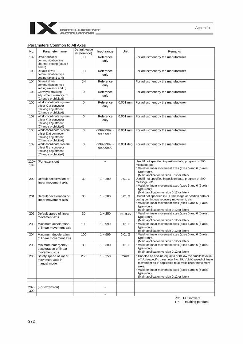
372
Appendix
Parameters Common to All Axes No. Parameter name Default value
(Reference) Input range Unit Remarks
102 Driver/encoder communication line channel setting (axes 5 and 6)
0H Reference only
For adjustment by the manufacturer
103 Default driver communication type setting (axes 1 to 4)
0H Reference only
For adjustment by the manufacturer
104 Default driver communication type setting (axes 5 and 6)
0H Reference only
For adjustment by the manufacturer
105 Conveyor tracking adjustment memory 01 (Change prohibited)
0 Reference only
For adjustment by the manufacturer
106 Work coordinate system offset X at conveyor tracking adjustment (Change prohibited)
0 Reference only
0.001 mm For adjustment by the manufacturer
107 Work coordinate system offset Y at conveyor tracking adjustment (Change prohibited)
0 Reference only
0.001 mm For adjustment by the manufacturer
108 Work coordinate system offset Z at conveyor tracking adjustment (Change prohibited)
0 -99999999 ~ 99999999
0.001 mm For adjustment by the manufacturer
109 Work coordinate system offset R at conveyor tracking adjustment (Change prohibited)
0 -99999999 ~ 99999999
0.001 deg For adjustment by the manufacturer
110~ 199
(For extension) ~ Used if not specified in position data, program or SIO message, etc. * Valid for linear movement axes (axes 5 and 6 (6-axis
type)) only. (Main application version 0.12 or later)
200 Default acceleration of linear movement axis
30 1 ~ 200 0.01 G Used if not specified in position data, program or SIO message, etc. * Valid for linear movement axes (axes 5 and 6 (6-axis
type)) only. (Main application version 0.12 or later)
201 Default deceleration of linear movement axis
30 1 ~ 200 0.01 G Used if not specified in SIO message or position data or during continuous recovery movement, etc. * Valid for linear movement axes (axes 5 and 6 (6-axis
type)) only. (Main application version 0.12 or later)
202 Default speed of linear movement axis
30 1 ~ 250 mm/sec * Valid for linear movement axes (axes 5 and 6 (6-axis type)) only. (Main application version 0.12 or later)
203 Maximum acceleration of linear movement axis
100 1 ~ 999 0.01 G * Valid for linear movement axes (axes 5 and 6 (6-axis type)) only. (Main application version 0.12 or later)
204 Maximum deceleration of linear movement axis
100 1 ~ 999 0.01 G * Valid for linear movement axes (axes 5 and 6 (6-axis type)) only. (Main application version 0.12 or later)
205 Minimum emergency deceleration of linear movement axis
30 1 ~ 300 0.01 G * Valid for linear movement axes (axes 5 and 6 (6-axis type)) only. (Main application version 0.12 or later)
206 Safety speed of linear movement axis in manual mode
250 1 ~ 250 mm/s * Handled as a value equal to or below the smallest value of “Axis-specific parameter No. 29, VLMX speed of linear movement axis” applicable to all valid linear movement axes.
* Valid for linear movement axes (axes 5 and 6 (6-axis type)) only. (Main application version 0.12 or later)
207~300
(For extension) ~
~ PC: PC software TP: Teaching pendant
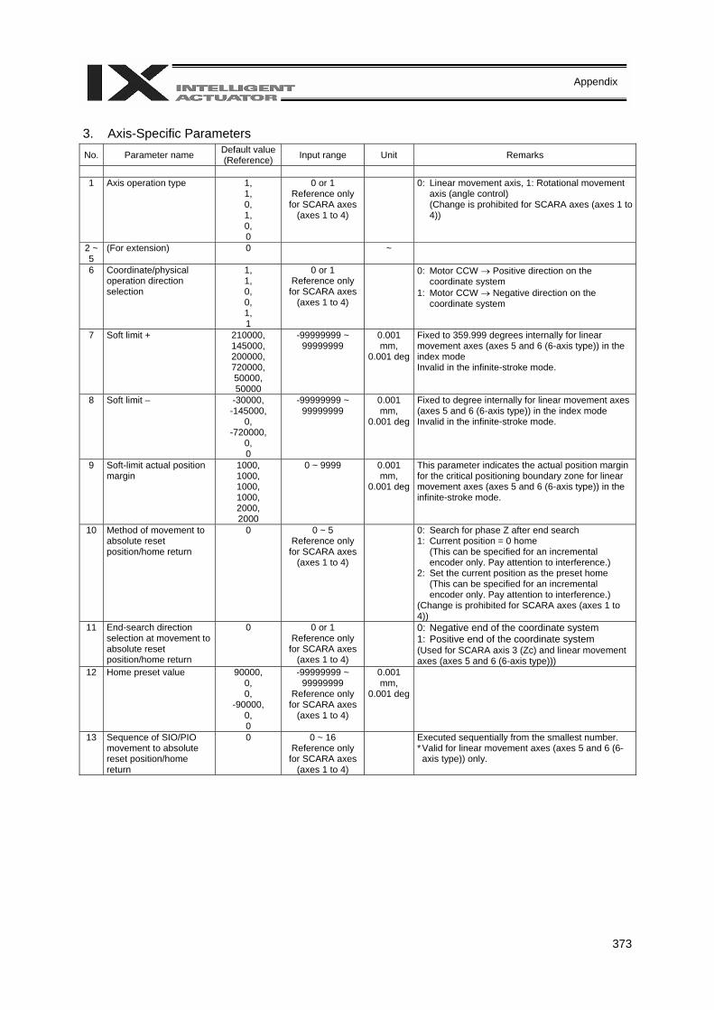
373
Appendix
3. Axis-Specific Parameters No. Parameter name Default value
(Reference) Input range Unit Remarks
1 Axis operation type 1,
1, 0, 1, 0, 0
0 or 1 Reference only
for SCARA axes (axes 1 to 4)
0: Linear movement axis, 1: Rotational movement axis (angle control) (Change is prohibited for SCARA axes (axes 1 to 4))
2 ~ 5
(For extension) 0 ~
6 Coordinate/physical operation direction selection
1, 1, 0, 0, 1, 1
0 or 1 Reference only
for SCARA axes (axes 1 to 4)
0: Motor CCW → Positive direction on the coordinate system
1: Motor CCW → Negative direction on the coordinate system
7 Soft limit + 210000, 145000, 200000, 720000, 50000, 50000
-99999999 ~ 99999999
0.001 mm,
0.001 deg
Fixed to 359.999 degrees internally for linear movement axes (axes 5 and 6 (6-axis type)) in the index mode Invalid in the infinite-stroke mode.
8 Soft limit – -30000, -145000,
0, -720000,
0, 0
-99999999 ~ 99999999
0.001 mm,
0.001 deg
Fixed to degree internally for linear movement axes (axes 5 and 6 (6-axis type)) in the index mode Invalid in the infinite-stroke mode.
9 Soft-limit actual position margin
1000, 1000, 1000, 1000, 2000, 2000
0 ~ 9999 0.001 mm,
0.001 deg
This parameter indicates the actual position margin for the critical positioning boundary zone for linear movement axes (axes 5 and 6 (6-axis type)) in the infinite-stroke mode.
10 Method of movement to absolute reset position/home return
0 0 ~ 5 Reference only
for SCARA axes (axes 1 to 4)
0: Search for phase Z after end search 1: Current position = 0 home
(This can be specified for an incremental encoder only. Pay attention to interference.)
2: Set the current position as the preset home (This can be specified for an incremental encoder only. Pay attention to interference.)
(Change is prohibited for SCARA axes (axes 1 to 4))
11 End-search direction selection at movement to absolute reset position/home return
0 0 or 1 Reference only
for SCARA axes (axes 1 to 4)
0: Negative end of the coordinate system 1: Positive end of the coordinate system (Used for SCARA axis 3 (Zc) and linear movement axes (axes 5 and 6 (6-axis type)))
12 Home preset value 90000, 0, 0,
-90000, 0, 0
-99999999 ~ 99999999
Reference only for SCARA axes
(axes 1 to 4)
0.001 mm,
0.001 deg
13 Sequence of SIO/PIO movement to absolute reset position/home return
0 0 ~ 16 Reference only
for SCARA axes (axes 1 to 4)
Executed sequentially from the smallest number. * Valid for linear movement axes (axes 5 and 6 (6-axis type)) only.
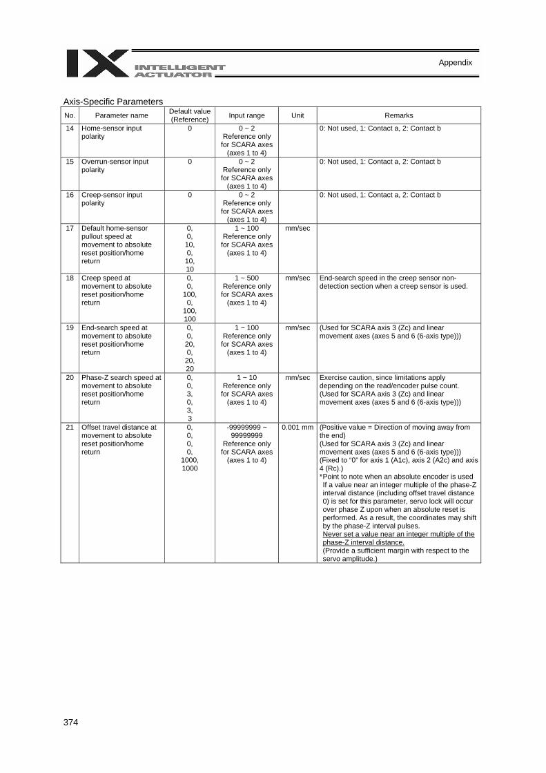
374
Appendix
Axis-Specific Parameters No. Parameter name Default value
(Reference) Input range Unit Remarks
14 Home-sensor input polarity
0 0 ~ 2 Reference only
for SCARA axes (axes 1 to 4)
0: Not used, 1: Contact a, 2: Contact b
15 Overrun-sensor input polarity
0 0 ~ 2 Reference only
for SCARA axes (axes 1 to 4)
0: Not used, 1: Contact a, 2: Contact b
16 Creep-sensor input polarity
0 0 ~ 2 Reference only
for SCARA axes (axes 1 to 4)
0: Not used, 1: Contact a, 2: Contact b
17 Default home-sensor pullout speed at movement to absolute reset position/home return
0, 0,
10, 0,
10, 10
1 ~ 100 Reference only
for SCARA axes (axes 1 to 4)
mm/sec
18 Creep speed at movement to absolute reset position/home return
0, 0,
100, 0,
100, 100
1 ~ 500 Reference only
for SCARA axes (axes 1 to 4)
mm/sec End-search speed in the creep sensor non-detection section when a creep sensor is used.
19 End-search speed at movement to absolute reset position/home return
0, 0,
20, 0,
20, 20
1 ~ 100 Reference only
for SCARA axes (axes 1 to 4)
mm/sec (Used for SCARA axis 3 (Zc) and linear movement axes (axes 5 and 6 (6-axis type)))
20 Phase-Z search speed at movement to absolute reset position/home return
0, 0, 3, 0, 3, 3
1 ~ 10 Reference only
for SCARA axes (axes 1 to 4)
mm/sec Exercise caution, since limitations apply depending on the read/encoder pulse count. (Used for SCARA axis 3 (Zc) and linear movement axes (axes 5 and 6 (6-axis type)))
21 Offset travel distance at movement to absolute reset position/home return
0, 0, 0, 0,
1000, 1000
-99999999 ~ 99999999
Reference only for SCARA axes
(axes 1 to 4)
0.001 mm (Positive value = Direction of moving away from the end) (Used for SCARA axis 3 (Zc) and linear movement axes (axes 5 and 6 (6-axis type))) (Fixed to “0” for axis 1 (A1c), axis 2 (A2c) and axis 4 (Rc).) * Point to note when an absolute encoder is used If a value near an integer multiple of the phase-Z interval distance (including offset travel distance 0) is set for this parameter, servo lock will occur over phase Z upon when an absolute reset is performed. As a result, the coordinates may shift by the phase-Z interval pulses. Never set a value near an integer multiple of the phase-Z interval distance. (Provide a sufficient margin with respect to the servo amplitude.)
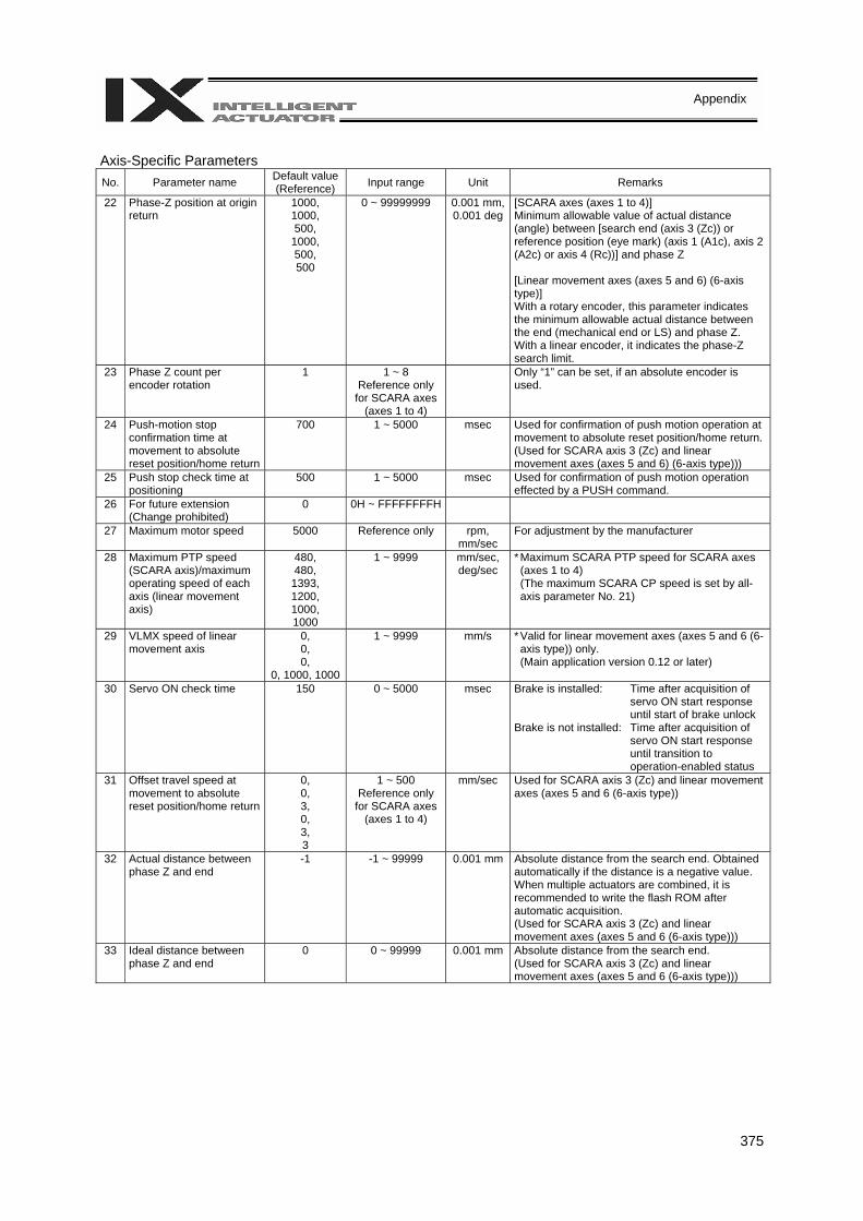
375
Appendix
Axis-Specific Parameters No. Parameter name Default value
(Reference) Input range Unit Remarks
22 Phase-Z position at origin return
1000, 1000, 500,
1000, 500, 500
0 ~ 99999999 0.001 mm, 0.001 deg
[SCARA axes (axes 1 to 4)] Minimum allowable value of actual distance (angle) between [search end (axis 3 (Zc)) or reference position (eye mark) (axis 1 (A1c), axis 2 (A2c) or axis 4 (Rc))] and phase Z [Linear movement axes (axes 5 and 6) (6-axis type)] With a rotary encoder, this parameter indicates the minimum allowable actual distance between the end (mechanical end or LS) and phase Z. With a linear encoder, it indicates the phase-Z search limit.
23 Phase Z count per encoder rotation
1 1 ~ 8 Reference only
for SCARA axes (axes 1 to 4)
Only “1” can be set, if an absolute encoder is used.
24 Push-motion stop confirmation time at movement to absolute reset position/home return
700 1 ~ 5000 msec Used for confirmation of push motion operation at movement to absolute reset position/home return. (Used for SCARA axis 3 (Zc) and linear movement axes (axes 5 and 6) (6-axis type)))
25 Push stop check time at positioning
500 1 ~ 5000 msec Used for confirmation of push motion operation effected by a PUSH command.
26 For future extension (Change prohibited)
0 0H ~ FFFFFFFFH
27 Maximum motor speed 5000 Reference only rpm, mm/sec
For adjustment by the manufacturer
28 Maximum PTP speed (SCARA axis)/maximum operating speed of each axis (linear movement axis)
480, 480,
1393, 1200, 1000, 1000
1 ~ 9999 mm/sec, deg/sec
* Maximum SCARA PTP speed for SCARA axes (axes 1 to 4) (The maximum SCARA CP speed is set by all-axis parameter No. 21)
29 VLMX speed of linear movement axis
0, 0, 0,
0, 1000, 1000
1 ~ 9999 mm/s * Valid for linear movement axes (axes 5 and 6 (6-axis type)) only. (Main application version 0.12 or later)
30 Servo ON check time 150 0 ~ 5000 msec Brake is installed: Time after acquisition of servo ON start response until start of brake unlock
Brake is not installed: Time after acquisition of servo ON start response until transition to operation-enabled status
31 Offset travel speed at movement to absolute reset position/home return
0, 0, 3, 0, 3, 3
1 ~ 500 Reference only
for SCARA axes (axes 1 to 4)
mm/sec Used for SCARA axis 3 (Zc) and linear movement axes (axes 5 and 6 (6-axis type))
32 Actual distance between phase Z and end
-1 -1 ~ 99999 0.001 mm Absolute distance from the search end. Obtained automatically if the distance is a negative value. When multiple actuators are combined, it is recommended to write the flash ROM after automatic acquisition. (Used for SCARA axis 3 (Zc) and linear movement axes (axes 5 and 6 (6-axis type)))
33 Ideal distance between phase Z and end
0 0 ~ 99999 0.001 mm Absolute distance from the search end. (Used for SCARA axis 3 (Zc) and linear movement axes (axes 5 and 6 (6-axis type)))
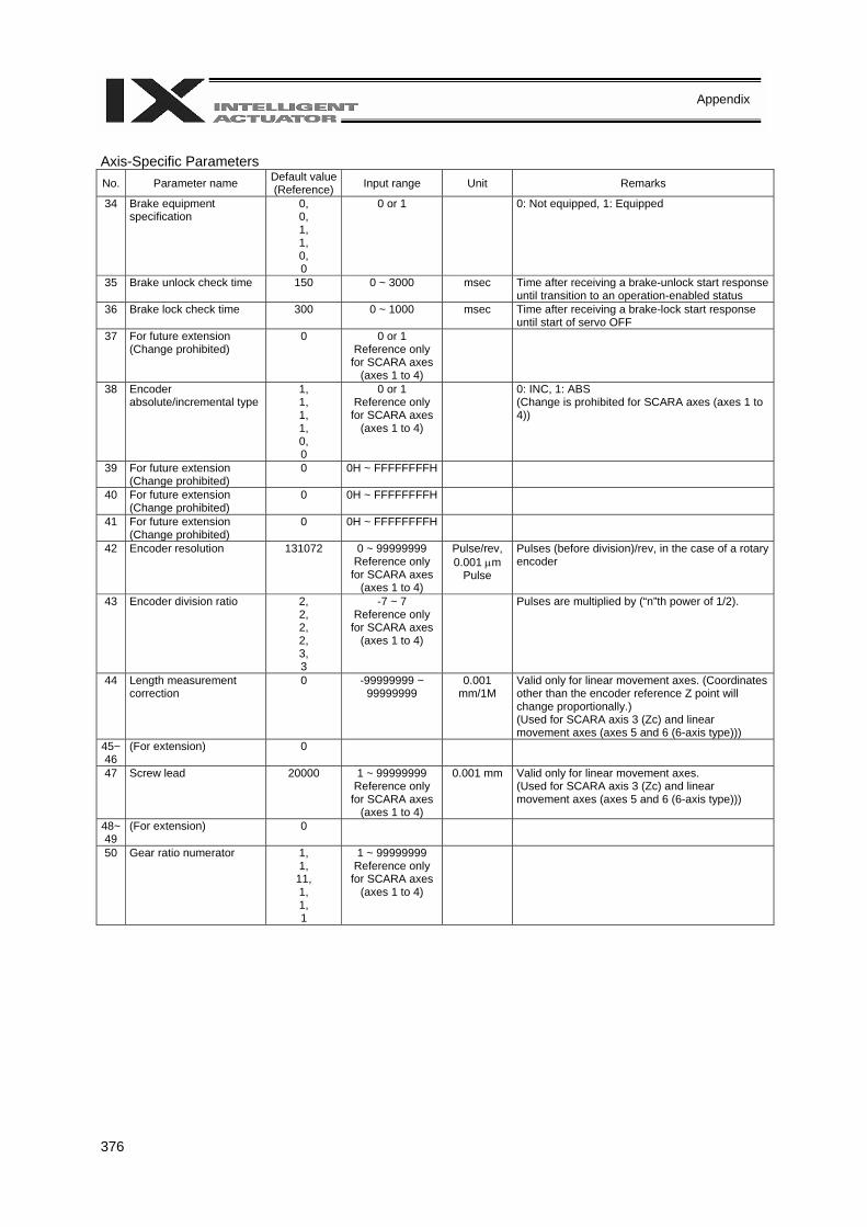
376
Appendix
Axis-Specific Parameters No. Parameter name Default value
(Reference) Input range Unit Remarks
34 Brake equipment specification
0, 0, 1, 1, 0, 0
0 or 1 0: Not equipped, 1: Equipped
35 Brake unlock check time 150 0 ~ 3000 msec Time after receiving a brake-unlock start response until transition to an operation-enabled status
36 Brake lock check time 300 0 ~ 1000 msec Time after receiving a brake-lock start response until start of servo OFF
37 For future extension (Change prohibited)
0 0 or 1 Reference only
for SCARA axes (axes 1 to 4)
38 Encoder absolute/incremental type
1, 1, 1, 1, 0, 0
0 or 1 Reference only
for SCARA axes (axes 1 to 4)
0: INC, 1: ABS (Change is prohibited for SCARA axes (axes 1 to 4))
39 For future extension (Change prohibited)
0 0H ~ FFFFFFFFH
40 For future extension (Change prohibited)
0 0H ~ FFFFFFFFH
41 For future extension (Change prohibited)
0 0H ~ FFFFFFFFH
42 Encoder resolution 131072 0 ~ 99999999 Reference only
for SCARA axes (axes 1 to 4)
Pulse/rev, 0.001 µm
Pulse
Pulses (before division)/rev, in the case of a rotary encoder
43 Encoder division ratio 2, 2, 2, 2, 3, 3
-7 ~ 7 Reference only
for SCARA axes (axes 1 to 4)
Pulses are multiplied by (“n”th power of 1/2).
44 Length measurement correction
0 -99999999 ~ 99999999
0.001 mm/1M
Valid only for linear movement axes. (Coordinates other than the encoder reference Z point will change proportionally.) (Used for SCARA axis 3 (Zc) and linear movement axes (axes 5 and 6 (6-axis type)))
45~46
(For extension) 0
47 Screw lead 20000 1 ~ 99999999 Reference only
for SCARA axes (axes 1 to 4)
0.001 mm Valid only for linear movement axes. (Used for SCARA axis 3 (Zc) and linear movement axes (axes 5 and 6 (6-axis type)))
48~49
(For extension) 0
50 Gear ratio numerator 1, 1,
11, 1, 1, 1
1 ~ 99999999 Reference only
for SCARA axes (axes 1 to 4)
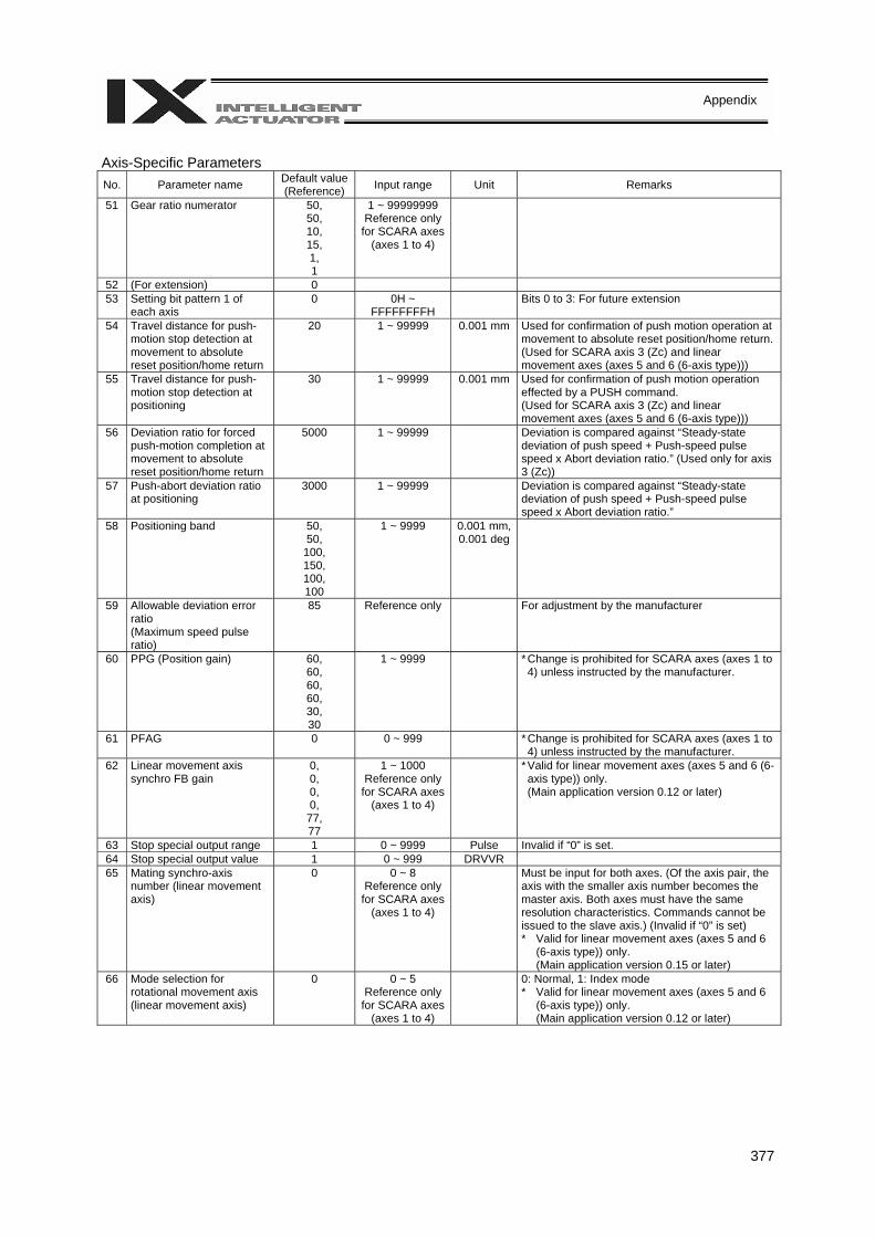
377
Appendix
Axis-Specific Parameters No. Parameter name Default value
(Reference) Input range Unit Remarks
51 Gear ratio numerator 50, 50, 10, 15, 1, 1
1 ~ 99999999 Reference only
for SCARA axes (axes 1 to 4)
52 (For extension) 0 53 Setting bit pattern 1 of
each axis 0 0H ~
FFFFFFFFH Bits 0 to 3: For future extension
54 Travel distance for push-motion stop detection at movement to absolute reset position/home return
20 1 ~ 99999 0.001 mm Used for confirmation of push motion operation at movement to absolute reset position/home return. (Used for SCARA axis 3 (Zc) and linear movement axes (axes 5 and 6 (6-axis type)))
55 Travel distance for push-motion stop detection at positioning
30 1 ~ 99999 0.001 mm Used for confirmation of push motion operation effected by a PUSH command. (Used for SCARA axis 3 (Zc) and linear movement axes (axes 5 and 6 (6-axis type)))
56 Deviation ratio for forced push-motion completion at movement to absolute reset position/home return
5000 1 ~ 99999 Deviation is compared against “Steady-state deviation of push speed + Push-speed pulse speed x Abort deviation ratio.” (Used only for axis 3 (Zc))
57 Push-abort deviation ratio at positioning
3000 1 ~ 99999 Deviation is compared against “Steady-state deviation of push speed + Push-speed pulse speed x Abort deviation ratio.”
58 Positioning band 50, 50,
100, 150, 100, 100
1 ~ 9999 0.001 mm, 0.001 deg
59 Allowable deviation error ratio (Maximum speed pulse ratio)
85 Reference only For adjustment by the manufacturer
60 PPG (Position gain) 60, 60, 60, 60, 30, 30
1 ~ 9999 * Change is prohibited for SCARA axes (axes 1 to 4) unless instructed by the manufacturer.
61 PFAG 0 0 ~ 999 * Change is prohibited for SCARA axes (axes 1 to 4) unless instructed by the manufacturer.
62 Linear movement axis synchro FB gain
0, 0, 0, 0,
77, 77
1 ~ 1000 Reference only
for SCARA axes (axes 1 to 4)
* Valid for linear movement axes (axes 5 and 6 (6-axis type)) only.
(Main application version 0.12 or later)
63 Stop special output range 1 0 ~ 9999 Pulse Invalid if “0” is set. 64 Stop special output value 1 0 ~ 999 DRVVR 65 Mating synchro-axis
number (linear movement axis)
0 0 ~ 8 Reference only
for SCARA axes (axes 1 to 4)
Must be input for both axes. (Of the axis pair, the axis with the smaller axis number becomes the master axis. Both axes must have the same resolution characteristics. Commands cannot be issued to the slave axis.) (Invalid if “0” is set) * Valid for linear movement axes (axes 5 and 6
(6-axis type)) only. (Main application version 0.15 or later)
66 Mode selection for rotational movement axis (linear movement axis)
0 0 ~ 5 Reference only
for SCARA axes (axes 1 to 4)
0: Normal, 1: Index mode * Valid for linear movement axes (axes 5 and 6
(6-axis type)) only. (Main application version 0.12 or later)
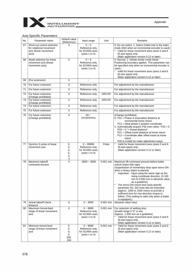
378
Appendix
Axis-Specific Parameters No. Parameter name Default value
(Reference) Input range Unit Remarks
67 Short-cut control selection for rotational movement axis (linear movement axis)
0 0 ~ 5 Reference only
for SCARA axes (axes 1 to 4)
0: Do not select, 1: Select (Valid only in the index mode AND when an incremental encoder is used)* Valid for linear movement axes (axes 5 and 6
(6-axis type)) only. (Main application version 0.12 or later)
68 Mode selection for linear movement axis (linear movement axis)
0 0 ~ 5 Reference only
for SCARA axes (axes 1 to 4)
0: Normal, 1: Infinite-stroke mode (Note: Positioning boundary applies. This parameter can be specified only when an incremental encoder is used.) * Valid for linear movement axes (axes 5 and 6
(6-axis type)) only. (Main application version 0.12 or later)
69 (For extension) 0 ~
70 For future extension 0 Reference only For adjustment by the manufacturer
71 For future extension 0 Reference only For adjustment by the manufacturer
72 For future extension (Change prohibited)
0 Reference only DRVVR For adjustment by the manufacturer
73 For future extension (Change prohibited)
0 Reference only DRVVR For adjustment by the manufacturer
74 For future extension 0 Reference only For adjustment by the manufacturer
75 For future extension 0 Reference only For adjustment by the manufacturer
76 For future extension (Change prohibited)
0 0H ~ FFFFFFFFH
(Change prohibited) 0: P21 = Phase-Z evacuation distance at
incremental home return P12 = Ideal phase-Z position coordinate 1: Automatically acquire P32 even when P33 = 0. P33 = 0 “= Actual distance” P21 = Offset travel distance at home return P12 = Coordinate after offset travel at home
return P26 is invalid (to make adjustment easy).
77 Synchro S pulse of linear movement axis
0, 0, 0, 0, 3, 3
0 ~ 99999 Reference only
for SCARA axes (axes 1 to 4)
Pulse * Valid for linear movement axes (axes 5 and 6 (6-axis type)) only.
(Main application version 0.12 or later)
78 Maximum takeoff command amount
0 -3000 ~ 3000 0.001 mm Maximum lift command amount before brake unlock (Input with sign) (Suppression of momentary drop upon servo ON when a heavy object is placed) * Important: Input using the same sign as the
rising coordinate direction. (0.100 mm to 0.500 mm in absolute value as a guideline)
* The servo-ON check time (axis-specific parameter No. 30) must also be extended (approx. 1000 to 1500 msec) to provide a sufficient time for rise-direction torque to follow. (This setting is valid only when a brake is equipped.)
79 Actual takeoff check distance
5 0 ~ 3000 0.001 mm Absolute value input
80 Maximum forced-feed range of linear movement axis
0 0 ~ 9999 Reference only
for SCARA axes (axes 1 to 4)
0.001 mm For reduction of settling time. (Invalid range if “0” is set) (Approx. 1.000 mm as a guideline) * Valid for linear movement axes (axes 5 and 6
(6-axis type)) only. (Main application version 0.12 or later)
81 Minimum forced-feed range of linear movement axis
0, 0, 0, 0,
200, 200
0 ~ 9999 Reference only
for SCARA axes (axes 1 to 4)
0.001 mm * Valid for linear movement axes (axes 5 and 6 (6-axis type)) only.
(Main application version 0.12 or later)
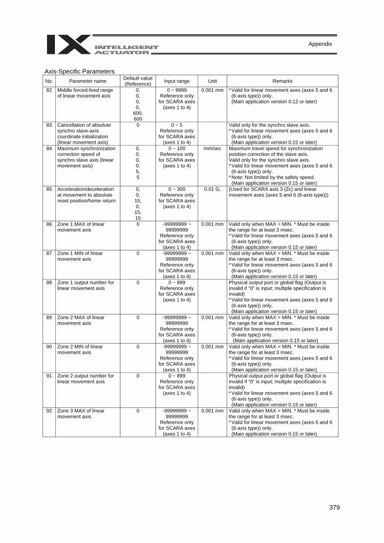
379
Appendix
Axis-Specific Parameters No. Parameter name Default value
(Reference) Input range Unit Remarks
82 Middle forced-feed range of linear movement axis
0, 0, 0, 0,
600, 600
0 ~ 9999 Reference only
for SCARA axes (axes 1 to 4)
0.001 mm * Valid for linear movement axes (axes 5 and 6 (6-axis type)) only.
(Main application version 0.12 or later)
83 Cancellation of absolute synchro slave-axis coordinate initialization (linear movement axis)
0 0 ~ 5 Reference only
for SCARA axes (axes 1 to 4)
Valid only for the synchro slave axis. * Valid for linear movement axes (axes 5 and 6 (6-axis type)) only. (Main application version 0.15 or later)
84 Maximum synchronization correction speed of synchro slave axis (linear movement axis)
0, 0, 0, 0, 5, 5
0 ~ 100 Reference only
for SCARA axes (axes 1 to 4)
mm/sec Maximum travel speed for synchronization position correction of the slave axis. Valid only for the synchro slave axis. * Valid for linear movement axes (axes 5 and 6 (6-axis type)) only.
* Note: Not limited by the safety speed. (Main application version 0.15 or later)
85 Acceleration/deceleration at movement to absolute reset position/home return
0, 0,
15, 0,
15, 15
0 ~ 300 Reference only
for SCARA axes (axes 1 to 4)
0.01 G, (Used for SCARA axis 3 (Zc) and linear movement axes (axes 5 and 6 (6-axis type)))
86 Zone 1 MAX of linear movement axis
0 -99999999 ~ 99999999
Reference only for SCARA axes
(axes 1 to 4)
0.001 mm Valid only when MAX > MIN. * Must be inside the range for at least 3 msec. * Valid for linear movement axes (axes 5 and 6 (6-axis type)) only. (Main application version 0.15 or later)
87 Zone 1 MIN of linear movement axis
0 -99999999 ~ 99999999
Reference only for SCARA axes
(axes 1 to 4)
0.001 mm Valid only when MAX > MIN. * Must be inside the range for at least 3 msec. * Valid for linear movement axes (axes 5 and 6 (6-axis type)) only. (Main application version 0.15 or later)
88 Zone 1 output number for linear movement axis
0 0 ~ 899 Reference only
for SCARA axes (axes 1 to 4)
Physical output port or global flag (Output is invalid if “0” is input; multiple specification is invalid) * Valid for linear movement axes (axes 5 and 6 (6-axis type)) only. (Main application version 0.15 or later)
89 Zone 2 MAX of linear movement axis
0 -99999999 ~ 99999999
Reference only for SCARA axes
(axes 1 to 4)
0.001 mm Valid only when MAX > MIN. * Must be inside the range for at least 3 msec. * Valid for linear movement axes (axes 5 and 6 (6-axis type)) only. (Main application version 0.15 or later)
90 Zone 2 MIN of linear movement axis
0 -99999999 ~ 99999999
Reference only for SCARA axes
(axes 1 to 4)
0.001 mm Valid only when MAX > MIN. * Must be inside the range for at least 3 msec. * Valid for linear movement axes (axes 5 and 6 (6-axis type)) only. (Main application version 0.15 or later)
91 Zone 2 output number for linear movement axis
0 0 ~ 899 Reference only
for SCARA axes (axes 1 to 4)
Physical output port or global flag (Output is invalid if “0” is input; multiple specification is invalid) * Valid for linear movement axes (axes 5 and 6 (6-axis type)) only. (Main application version 0.15 or later)
92 Zone 3 MAX of linear movement axis
0 -99999999 ~ 99999999
Reference only for SCARA axes
(axes 1 to 4)
0.001 mm Valid only when MAX > MIN. * Must be inside the range for at least 3 msec. * Valid for linear movement axes (axes 5 and 6 (6-axis type)) only. (Main application version 0.15 or later)
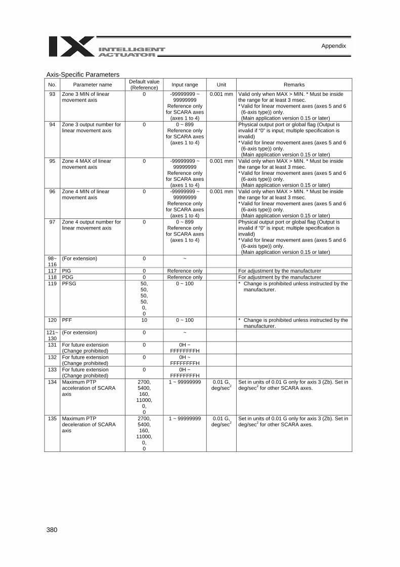
380
Appendix
Axis-Specific Parameters No. Parameter name Default value
(Reference) Input range Unit Remarks
93 Zone 3 MIN of linear movement axis
0 -99999999 ~ 99999999
Reference only for SCARA axes
(axes 1 to 4)
0.001 mm Valid only when MAX > MIN. * Must be inside the range for at least 3 msec. * Valid for linear movement axes (axes 5 and 6 (6-axis type)) only. (Main application version 0.15 or later)
94 Zone 3 output number for linear movement axis
0 0 ~ 899 Reference only
for SCARA axes (axes 1 to 4)
Physical output port or global flag (Output is invalid if “0” is input; multiple specification is invalid) * Valid for linear movement axes (axes 5 and 6 (6-axis type)) only. (Main application version 0.15 or later)
95 Zone 4 MAX of linear movement axis
0 -99999999 ~ 99999999
Reference only for SCARA axes
(axes 1 to 4)
0.001 mm Valid only when MAX > MIN. * Must be inside the range for at least 3 msec. * Valid for linear movement axes (axes 5 and 6 (6-axis type)) only. (Main application version 0.15 or later)
96 Zone 4 MIN of linear movement axis
0 -99999999 ~ 99999999
Reference only for SCARA axes
(axes 1 to 4)
0.001 mm Valid only when MAX > MIN. * Must be inside the range for at least 3 msec. * Valid for linear movement axes (axes 5 and 6 (6-axis type)) only. (Main application version 0.15 or later)
97 Zone 4 output number for linear movement axis
0 0 ~ 899 Reference only
for SCARA axes (axes 1 to 4)
Physical output port or global flag (Output is invalid if “0” is input; multiple specification is invalid) * Valid for linear movement axes (axes 5 and 6 (6-axis type)) only. (Main application version 0.15 or later)
98~ 116
(For extension) 0 ~
117 PIG 0 Reference only For adjustment by the manufacturer 118 PDG 0 Reference only For adjustment by the manufacturer 119 PFSG 50,
50, 50, 50, 0, 0
0 ~ 100 * Change is prohibited unless instructed by the manufacturer.
120 PFF 10 0 ~ 100 * Change is prohibited unless instructed by the manufacturer.
121~130
(For extension) 0 ~
131 For future extension (Change prohibited)
0 0H ~ FFFFFFFFH
132 For future extension (Change prohibited)
0 0H ~ FFFFFFFFH
133 For future extension (Change prohibited)
0 0H ~ FFFFFFFFH
134 Maximum PTP acceleration of SCARA axis
2700, 5400, 160,
11000, 0, 0
1 ~ 99999999 0.01 G, deg/sec2
Set in units of 0.01 G only for axis 3 (Zb). Set in deg/sec2 for other SCARA axes.
135 Maximum PTP deceleration of SCARA axis
2700, 5400, 160,
11000, 0, 0
1 ~ 99999999 0.01 G, deg/sec2
Set in units of 0.01 G only for axis 3 (Zb). Set in deg/sec2 for other SCARA axes.
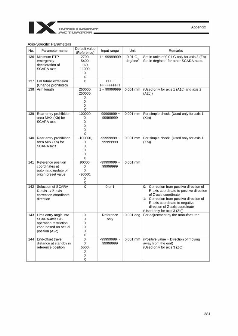
381
Appendix
Axis-Specific Parameters No. Parameter name Default value
(Reference) Input range Unit Remarks
136 Minimum PTP emergency deceleration of SCARA axis
2700, 5400, 160,
11000, 0, 0
1 ~ 99999999 0.01 G, deg/sec2
Set in units of 0.01 G only for axis 3 (Zb). Set in deg/sec2 for other SCARA axes.
137 For future extension (Change prohibited)
0 0H ~ FFFFFFFFH
138 Arm length 250000, 250000,
0, 0, 0, 0
1 ~ 99999999 0.001 mm (Used only for axis 1 (A1c) and axis 2 (A2c))
139 Rear entry prohibition area MAX (Xb) for SCARA axis
100000, 0, 0, 0, 0, 0
-99999999 ~ 99999999
0.001 mm For simple check. (Used only for axis 1 (Xb))
140 Rear entry prohibition area MIN (Xb) for SCARA axis
-100000, 0, 0, 0, 0, 0
-99999999 ~ 99999999
0.001 mm For simple check. (Used only for axis 1 (Xb))
141 Reference position coordinates at automatic update of origin preset value
90000, 0, 0,
-90000, 0, 0
-99999999 ~ 99999999
0.001 mm
142 Selection of SCARA R-axis → Z-axis correction coordinate direction
0 0 or 1 0: Correction from positive direction of R-axis coordinate to positive direction of Z-axis coordinate
1: Correction from positive direction of R-axis coordinate to negative direction of Z-axis coordinate
(Used only for axis 3 (Zc)) 143 Limit entry angle into
SCARA-axis CP-operation restriction zone based on actual position (A2c)
0, 0, 0, 0, 0, 0
Reference only
0.001 deg For adjustment by the manufacturer
144 End-offset travel distance at standby in reference position
0, 0,
5500, 0, 0, 0
-99999999 ~ 99999999
0.001 mm (Positive value = Direction of moving away from the end) (Used only for axis 3 (Zc))
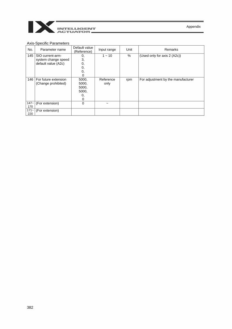
382
Appendix
Axis-Specific Parameters No. Parameter name Default value
(Reference) Input range Unit Remarks
145 SIO current-arm-system change speed default value (A2c)
0, 3, 0, 0, 0, 0
1 ~ 10 % (Used only for axis 2 (A2c))
146 For future extension (Change prohibited)
5000, 5000, 5000, 5000,
0, 0
Reference only
rpm For adjustment by the manufacturer
147~170
(For extension) 0 ~
171~220
(For extension)
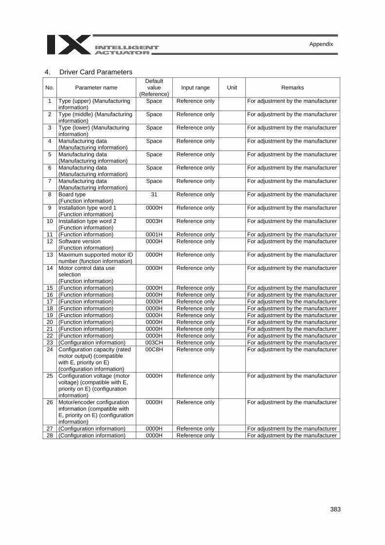
383
Appendix
4. Driver Card Parameters
No. Parameter name Default value
(Reference) Input range Unit Remarks
1 Type (upper) (Manufacturing information)
Space Reference only For adjustment by the manufacturer
2 Type (middle) (Manufacturing information)
Space Reference only For adjustment by the manufacturer
3 Type (lower) (Manufacturing information)
Space Reference only For adjustment by the manufacturer
4 Manufacturing data (Manufacturing information)
Space Reference only For adjustment by the manufacturer
5 Manufacturing data (Manufacturing information)
Space Reference only For adjustment by the manufacturer
6 Manufacturing data (Manufacturing information)
Space Reference only For adjustment by the manufacturer
7 Manufacturing data (Manufacturing information)
Space Reference only For adjustment by the manufacturer
8 Board type (Function information)
31 Reference only For adjustment by the manufacturer
9 Installation type word 1 (Function information)
0000H Reference only For adjustment by the manufacturer
10 Installation type word 2 (Function information)
0003H Reference only For adjustment by the manufacturer
11 (Function information) 0001H Reference only For adjustment by the manufacturer12 Software version
(Function information) 0000H Reference only For adjustment by the manufacturer
13 Maximum supported motor ID number (function information)
0000H Reference only For adjustment by the manufacturer
14 Motor control data use selection (Function information)
0000H Reference only For adjustment by the manufacturer
15 (Function information) 0000H Reference only For adjustment by the manufacturer16 (Function information) 0000H Reference only For adjustment by the manufacturer17 (Function information) 0000H Reference only For adjustment by the manufacturer18 (Function information) 0000H Reference only For adjustment by the manufacturer19 (Function information) 0000H Reference only For adjustment by the manufacturer20 (Function information) 0000H Reference only For adjustment by the manufacturer21 (Function information) 0000H Reference only For adjustment by the manufacturer22 (Function information) 0000H Reference only For adjustment by the manufacturer23 (Configuration information) 003CH Reference only For adjustment by the manufacturer24 Configuration capacity (rated
motor output) (compatible with E, priority on E) (configuration information)
00C8H Reference only For adjustment by the manufacturer
25 Configuration voltage (motor voltage) (compatible with E, priority on E) (configuration information)
0000H Reference only For adjustment by the manufacturer
26 Motor/encoder configuration information (compatible with E, priority on E) (configuration information)
0000H Reference only For adjustment by the manufacturer
27 (Configuration information) 0000H Reference only For adjustment by the manufacturer28 (Configuration information) 0000H Reference only For adjustment by the manufacturer
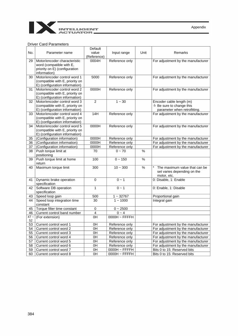
384
Appendix
Driver Card Parameters
No. Parameter name Default value
(Reference) Input range Unit Remarks
29 Motor/encoder characteristic word (compatible with E, priority on E) (configuration information)
0004H Reference only For adjustment by the manufacturer
30 Motor/encoder control word 1 (compatible with E, priority on E) (configuration information)
5000 Reference only For adjustment by the manufacturer
31 Motor/encoder control word 2 (compatible with E, priority on E) (configuration information)
0000H Reference only For adjustment by the manufacturer
32 Motor/encoder control word 3 (compatible with E, priority on E) (configuration information)
2 1 ~ 30 Encoder cable length (m) Be sure to change this parameter when retrofitting.
33 Motor/encoder control word 4 (compatible with E, priority on E) (configuration information)
14H Reference only For adjustment by the manufacturer
34 Motor/encoder control word 5 (compatible with E, priority on E) (configuration information)
0000H Reference only For adjustment by the manufacturer
35 (Configuration information) 0000H Reference only For adjustment by the manufacturer36 (Configuration information) 0000H Reference only For adjustment by the manufacturer37 (Configuration information) 0000H Reference only For adjustment by the manufacturer38 Push torque limit at
positioning 70 0 ~ 70 %
39 Push torque limit at home return
100 0 ~ 150 %
40 Maximum torque limit 300 10 ~ 300 % * The maximum value that can be set varies depending on the motor, etc.
41 Dynamic brake operation specification
0 0 ~ 1 0: Disable, 1: Enable
42 Software DB operation specification
1 0 ~ 1 0: Enable, 1: Disable
43 Speed loop gain 500 1 ~ 32767 Proportional gain 44 Speed loop integration time
constant 30 1 ~ 1000 Integral gain
45 Torque filter time constant 0 0 ~ 2500 46 Current control band number 4 0 ~ 4
47 ~ 52
(For extension) 0H 0000H ~ FFFFH
53 Current control word 1 0H Reference only For adjustment by the manufacturer54 Current control word 2 0H Reference only For adjustment by the manufacturer55 Current control word 3 0H Reference only For adjustment by the manufacturer56 Current control word 4 0H Reference only For adjustment by the manufacturer57 Current control word 5 0H Reference only For adjustment by the manufacturer58 Current control word 6 0H Reference only For adjustment by the manufacturer59 Current control word 7 0H 0000H ~ FFFFH Bits 0 to 15: Reserved bits 60 Current control word 8 0H 0000H ~ FFFFH Bits 0 to 15: Reserved bits
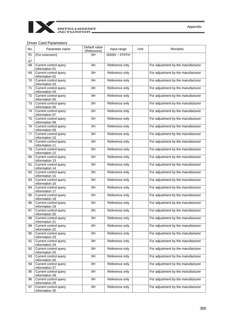
385
Appendix
Driver Card Parameters No. Parameter name Default value
(Reference) Input range Unit Remarks
61 ~ 67
(For extension) 0H 0000H ~ FFFFH
68 Current control query information 01
0H Reference only For adjustment by the manufacturer
69 Current control query information 02
0H Reference only For adjustment by the manufacturer
70 Current control query information 03
0H Reference only For adjustment by the manufacturer
71 Current control query information 04
0H Reference only For adjustment by the manufacturer
72 Current control query information 05
0H Reference only For adjustment by the manufacturer
73 Current control query information 06
0H Reference only For adjustment by the manufacturer
74 Current control query information 07
0H Reference only For adjustment by the manufacturer
75 Current control query information 08
0H Reference only For adjustment by the manufacturer
76 Current control query information 09
0H Reference only For adjustment by the manufacturer
77 Current control query information 10
0H Reference only For adjustment by the manufacturer
78 Current control query information 11
0H Reference only For adjustment by the manufacturer
79 Current control query information 12
0H Reference only For adjustment by the manufacturer
80 Current control query information 13
0H Reference only For adjustment by the manufacturer
81 Current control query information 14
0H Reference only For adjustment by the manufacturer
82 Current control query information 15
0H Reference only For adjustment by the manufacturer
83 Current control query information 16
0H Reference only For adjustment by the manufacturer
84 Current control query information 17
0H Reference only For adjustment by the manufacturer
85 Current control query information 18
0H Reference only For adjustment by the manufacturer
86 Current control query information 19
0H Reference only For adjustment by the manufacturer
87 Current control query information 20
0H Reference only For adjustment by the manufacturer
88 Current control query information 21
0H Reference only For adjustment by the manufacturer
89 Current control query information 22
0H Reference only For adjustment by the manufacturer
90 Current control query information 23
0H Reference only For adjustment by the manufacturer
91 Current control query information 24
0H Reference only For adjustment by the manufacturer
92 Current control query information 25
0H Reference only For adjustment by the manufacturer
93 Current control query information 26
0H Reference only For adjustment by the manufacturer
94 Current control query information 27
0H Reference only For adjustment by the manufacturer
95 Current control query information 28
0H Reference only For adjustment by the manufacturer
96 Current control query information 29
0H Reference only For adjustment by the manufacturer
97 Current control query information 30
0H Reference only For adjustment by the manufacturer
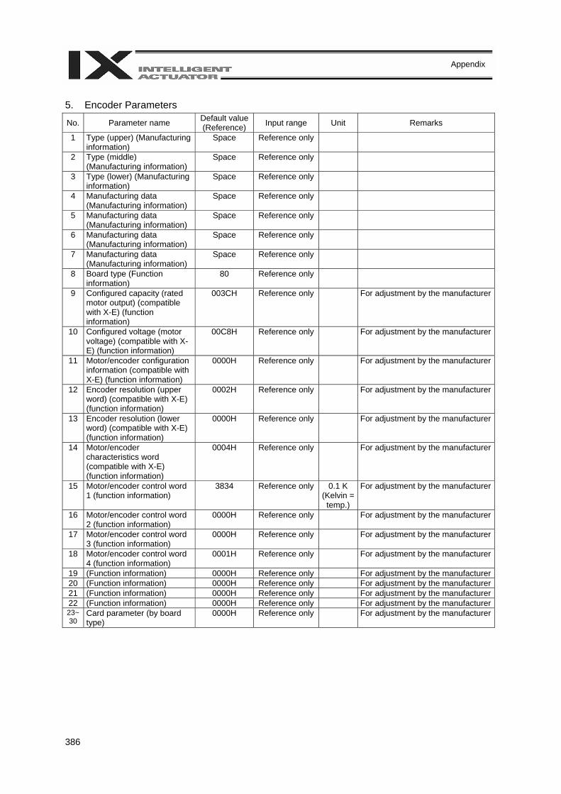
386
Appendix
5. Encoder Parameters
No. Parameter name Default value (Reference) Input range Unit Remarks
1 Type (upper) (Manufacturing information)
Space Reference only
2 Type (middle) (Manufacturing information)
Space Reference only
3 Type (lower) (Manufacturing information)
Space Reference only
4 Manufacturing data (Manufacturing information)
Space Reference only
5 Manufacturing data (Manufacturing information)
Space Reference only
6 Manufacturing data (Manufacturing information)
Space Reference only
7 Manufacturing data (Manufacturing information)
Space Reference only
8 Board type (Function information)
80 Reference only
9 Configured capacity (rated motor output) (compatible with X-E) (function information)
003CH Reference only For adjustment by the manufacturer
10 Configured voltage (motor voltage) (compatible with X-E) (function information)
00C8H Reference only For adjustment by the manufacturer
11 Motor/encoder configuration information (compatible with X-E) (function information)
0000H Reference only For adjustment by the manufacturer
12 Encoder resolution (upper word) (compatible with X-E) (function information)
0002H Reference only For adjustment by the manufacturer
13 Encoder resolution (lower word) (compatible with X-E) (function information)
0000H Reference only For adjustment by the manufacturer
14 Motor/encoder characteristics word (compatible with X-E) (function information)
0004H Reference only For adjustment by the manufacturer
15 Motor/encoder control word 1 (function information)
3834 Reference only 0.1 K (Kelvin = temp.)
For adjustment by the manufacturer
16 Motor/encoder control word 2 (function information)
0000H Reference only For adjustment by the manufacturer
17 Motor/encoder control word 3 (function information)
0000H Reference only For adjustment by the manufacturer
18 Motor/encoder control word 4 (function information)
0001H Reference only For adjustment by the manufacturer
19 (Function information) 0000H Reference only For adjustment by the manufacturer20 (Function information) 0000H Reference only For adjustment by the manufacturer21 (Function information) 0000H Reference only For adjustment by the manufacturer22 (Function information) 0000H Reference only For adjustment by the manufacturer23~30
Card parameter (by board type)
0000H Reference only For adjustment by the manufacturer
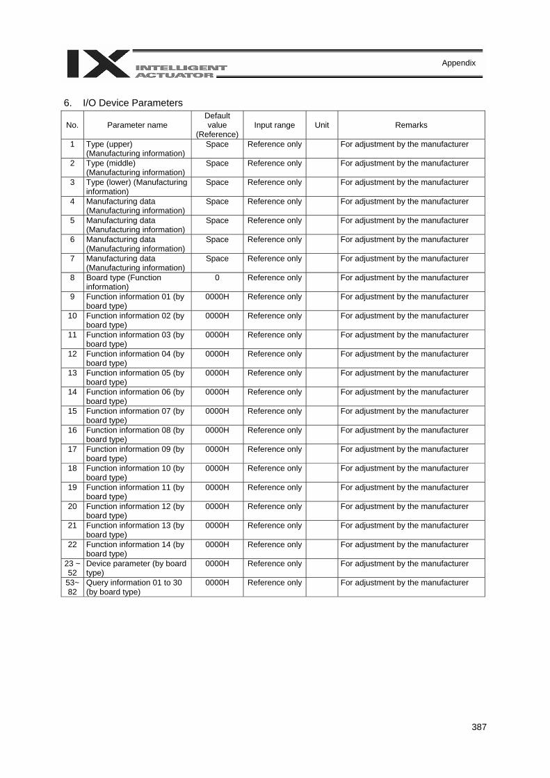
387
Appendix
6. I/O Device Parameters
No. Parameter name Default value
(Reference) Input range Unit Remarks
1 Type (upper) (Manufacturing information)
Space Reference only For adjustment by the manufacturer
2 Type (middle) (Manufacturing information)
Space Reference only For adjustment by the manufacturer
3 Type (lower) (Manufacturing information)
Space Reference only For adjustment by the manufacturer
4 Manufacturing data (Manufacturing information)
Space Reference only For adjustment by the manufacturer
5 Manufacturing data (Manufacturing information)
Space Reference only For adjustment by the manufacturer
6 Manufacturing data (Manufacturing information)
Space Reference only For adjustment by the manufacturer
7 Manufacturing data (Manufacturing information)
Space Reference only For adjustment by the manufacturer
8 Board type (Function information)
0 Reference only For adjustment by the manufacturer
9 Function information 01 (by board type)
0000H Reference only For adjustment by the manufacturer
10 Function information 02 (by board type)
0000H Reference only For adjustment by the manufacturer
11 Function information 03 (by board type)
0000H Reference only For adjustment by the manufacturer
12 Function information 04 (by board type)
0000H Reference only For adjustment by the manufacturer
13 Function information 05 (by board type)
0000H Reference only For adjustment by the manufacturer
14 Function information 06 (by board type)
0000H Reference only For adjustment by the manufacturer
15 Function information 07 (by board type)
0000H Reference only For adjustment by the manufacturer
16 Function information 08 (by board type)
0000H Reference only For adjustment by the manufacturer
17 Function information 09 (by board type)
0000H Reference only For adjustment by the manufacturer
18 Function information 10 (by board type)
0000H Reference only For adjustment by the manufacturer
19 Function information 11 (by board type)
0000H Reference only For adjustment by the manufacturer
20 Function information 12 (by board type)
0000H Reference only For adjustment by the manufacturer
21 Function information 13 (by board type)
0000H Reference only For adjustment by the manufacturer
22 Function information 14 (by board type)
0000H Reference only For adjustment by the manufacturer
23 ~ 52
Device parameter (by board type)
0000H Reference only For adjustment by the manufacturer
53~ 82
Query information 01 to 30 (by board type)
0000H Reference only For adjustment by the manufacturer

388
Appendix
7. Other Parameters No. Parameter name Default value
(Reference) Input range Unit Remarks
1 Auto-start program number
0 0 ~ 64 (Invalid if “0” is set)
2 I/O processing program number at operation/program abort
0 0 ~ 64 The start trigger is determined from the “I/O processing program start type at operation/program abort.” (Note: This program will be started before confirming an abort of other programs.) (Invalid if “0” is set) * If the setting is valid, the number of user program tasks that can be used will decrease by 1.
3 I/O processing program number at all operation pause
0 0 ~ 64 This program will be started when an all-operation-pause command is issued due to an all-operation-pause factor. (Only when a program is running) (Invalid if “0” is set) * If the setting is valid, the number of user program tasks that can be used will decrease by 1.
4 Program abort type at error
0 0 ~ 5 0: Cancel only the program in which an error of operation-cancellation level or higher has generated. (If the error requires the drive source to be cut off, servo OFF or all-axis servo OFF, all programs other than the “I/O processing program at operation/program abort” will be cancelled.)
1: Cancel all programs other than the “I/O processing program at operation/program abort” when an error of operation-cancellation level or higher has generated.
5 I/O processing program start type at operation/program abort
0 0 ~ 5 0: When all-operation-cancellation factor has generated (Only when a program is running)
1: When all-operation-cancellation factor has generated (Always)
2: All-operation-cancellation factor + Error of operation-cancellation level or higher (“Other parameter No. 4 = 0” is considered) (Only when a program is running)
3: All-operation-cancellation factor + Error of operation-cancellation level or higher (“Other parameter No. 4 = 0” is considered) (Always)
6 PC/TP reconnection delay at software reset
14000 1 ~ 99999 msec * The setting will become effective after the controller, PC software or TP is restarted.
7~8 (For extension) 0 9 For future extension
(Change prohibited) 0 0 ~ 9
10 Emergency-stop recovery type
0 0 ~ 4 0: Abort operations/programs 1: Recovery after reset 2: Operation continued (Only during automatic
operation. * Operation commands from the PC software/TP will
be aborted from the PC software/TP side.) 3: Abort operations/programs (Software reset when the
emergency stop is reset. The origin-return completion status of incremental-encoder axes will be reset (EG approximation swap)).
4: Abort operations/programs (Error reset (only with an error of operation-cancellation level or lower) and auto-start program start (only if AUTO mode AND I/O parameter No. 33 = 1 AND I/O parameter No. 44 ≠ 1 AND all-operation-cancellation factor is not present) when the emergency stop is reset). There must be a minimum interval of 1 second after an emergency stop is actuated before it is reset. The origin-return completion status of incremental-encoder axes will be retained.)
11 Enable switch (deadman switch/enable switch) recovery type
0 0 ~ 2 0: Abort operations/programs 1: Recovery after reset 2: Operation continued (Only during automatic
operation. * Operation commands from the PC software/TP will be aborted from the PC software/TP side.)
PC: PC software TP: Teaching pendant
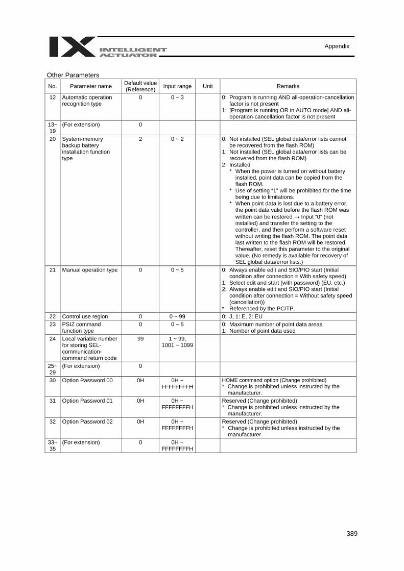
389
Appendix
Other Parameters No. Parameter name Default value
(Reference) Input range Unit Remarks
12 Automatic operation recognition type
0 0 ~ 3 0: Program is running AND all-operation-cancellation factor is not present
1: [Program is running OR in AUTO mode] AND all-operation-cancellation factor is not present
13~19
(For extension) 0
20 System-memory backup battery installation function type
2 0 ~ 2 0: Not installed (SEL global data/error lists cannot be recovered from the flash ROM)
1: Not installed (SEL global data/error lists can be recovered from the flash ROM)
2: Installed * When the power is turned on without battery
installed, point data can be copied from the flash ROM.
* Use of setting “1” will be prohibited for the time being due to limitations.
* When point data is lost due to a battery error, the point data valid before the flash ROM was written can be restored → Input “0” (not installed) and transfer the setting to the controller, and then perform a software reset without writing the flash ROM. The point data last written to the flash ROM will be restored. Thereafter, reset this parameter to the original value. (No remedy is available for recovery of SEL global data/error lists.)
21 Manual operation type 0 0 ~ 5 0: Always enable edit and SIO/PIO start (Initial condition after connection = With safety speed)
1: Select edit and start (with password) (EU, etc.) 2: Always enable edit and SIO/PIO start (Initial
condition after connection = Without safety speed (cancellation))
* Referenced by the PC/TP. 22 Control use region 0 0 ~ 99 0: J, 1: E, 2: EU 23 PSIZ command
function type 0 0 ~ 5 0: Maximum number of point data areas
1: Number of point data used 24 Local variable number
for storing SEL-communication-command return code
99 1 ~ 99, 1001 ~ 1099
25~29
(For extension) 0
30 Option Password 00 0H 0H ~ FFFFFFFFH
HOME command option (Change prohibited) * Change is prohibited unless instructed by the
manufacturer. 31 Option Password 01 0H 0H ~
FFFFFFFFH Reserved (Change prohibited)
* Change is prohibited unless instructed by the manufacturer.
32 Option Password 02 0H 0H ~ FFFFFFFFH
Reserved (Change prohibited) * Change is prohibited unless instructed by the
manufacturer. 33~35
(For extension) 0 0H ~ FFFFFFFFH

390
Appendix
Other Parameters
No. Parameter name Default value (Reference) Input range Unit Remarks
36 PC/TP data protect setting (Program)
0H 0H ~ FFFFFFFFH
Bits 0 to 3: Protect type (0: Read/write, 1: Read only, 2: No read/write)
Bits 4 to 7: Protect release method (0: Special operation)
Bits 8 to 11: Protect range maximum number (1’s place, BCD)
Bits 12 to 15: Protect range maximum number (10’s place, BCD)
Bits 16 to 19: Protect range minimum number (1’s place, BCD)
Bits 20 to 23: Protect range minimum number (10’s place, BCD)
* Referenced by the PC/TP 37 PC/TP data protect
setting (Position) 0H 0H ~
FFFFFFFFH Bits 0 to 3: Protect type (0: Read/write, 1: Read
only, 2: No read/write) Bits 4 to 7: Protect release method (0: Special
operation) Bits 8 to 11: Protect range maximum number (10’s
place, BCD) Bits 12 to 15: Protect range maximum number (100’s
place, BCD) Bits 16 to 19: Protect range maximum number
(1000’s place, BCD) Bits 20 to 23: Protect range minimum number (10’s
place, BCD) Bits 24 to 27: Protect range minimum number (100’s
place, BCD) Bits 28 to 31: Protect range minimum number
(1000’s place, BCD) * The value in the 1’s place is considered “0” for
both the protect range maximum/minimum numbers.
* Referenced by the PC/TP 38 PC/TP data protect
setting (Symbol, parameter)
0H 0H ~ FFFFFFFFH
Bits 0 to 3: Protect type (Parameter) (0: Read/write, 1: Read only, 2: No read/write)
Bits 4 to 7: Protect release method (Parameter) (0: Special operation)
Bits 8 to 11: Protect type (Symbol) (0: Read/write, 1: Read only, 2: No read/write)
Bits 12 to 15: Protect release method (Symbol) (0: Special operation)
* Referenced by the PC/TP
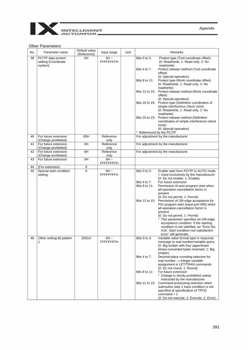
391
Appendix
Other Parameters No. Parameter name Default value
(Reference) Input range Unit Remarks
39 PC/TP data protect setting (Coordinate system)
0H 0H ~ FFFFFFFFH
Bits 0 to 3: Protect type (Tool coordinate offset) (0: Read/write, 1: Read only, 2: No read/write)
Bits 4 to 7: Protect release method (Tool coordinate offset) (0: Special operation)
Bits 8 to 11: Protect type (Work coordinate offset) (0: Read/write, 1: Read only, 2: No read/write)
Bits 12 to 15: Protect release method (Work coordinate offset) (0: Special operation)
Bits 16 to 19: Protect type (Definition coordinates of simple interference check zone) (0: Read/write, 1: Read only, 2: No read/write)
Bits 20 to 23: Protect release method (Definition coordinates of simple interference check zone) (0: Special operation)
* Referenced by the PC/TP 40 For future extension
(Change prohibited) 83H Reference
only For adjustment by the manufacturer
41 For future extension (Change prohibited)
0H Reference only
For adjustment by the manufacturer
42 For future extension (Change prohibited)
6H Reference only
For adjustment by the manufacturer
43 For future extension 0H 0H ~ FFFFFFFFH
44 (For extension) 0 45 Special start condition
setting 0 0H ~
FFFFFFFFH Bits 0 to 3: Enable start from PC/TP in AUTO mode
= Used exclusively by the manufacturer (0: Do not enable, 1: Enable)
Bits 4 to 7: For future extension Bits 8 to 11: Permission of auto program start when
all-operation-cancellation factor is present (0: Do not permit, 1: Permit)
Bits 12 to 15: Permission of ON edge acceptance for PIO program start (input port 000) when all-operation-cancellation factor is present (0: Do not permit, 1: Permit) * This parameter specifies an ON-edge
acceptance condition. If the starting condition is not satisfied, an "Error No. A1E: Start condition non-satisfaction error" will generate.
46 Other setting bit pattern 1
2001H 0H ~ FFFFFFFFH
Bits 0 to 3: Variable-value format type in response message to real-number/variable query (0: Big endian with four upper/lower binary-converted bytes reversed, 1: Big endian)
Bits 4 to 7: Decimal-place rounding selection for real-number → integer-variable assignment in LET/TRAN commands
(0: Do not round, 1: Round) Bits 8 to 11: For future extension
* Change is strictly prohibited unless instructed by the manufacturer.
Bits 12 to 15: Command processing selection when subroutine step 1 input condition is not specified at specification of TPCD command = 1 (0: Do not execute, 1: Execute, 2: Error)
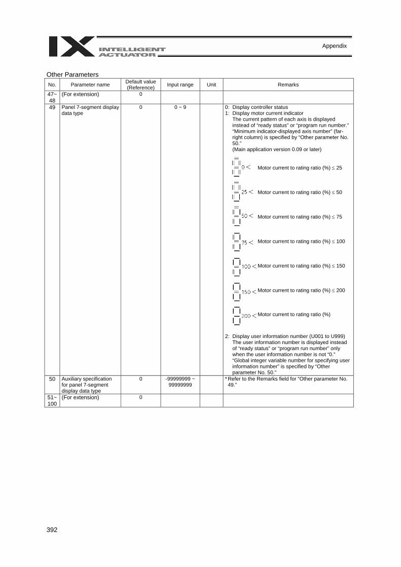
392
Appendix
Other Parameters No. Parameter name Default value
(Reference) Input range Unit Remarks
47~48
(For extension) 0
49 Panel 7-segment display data type
0 0 ~ 9 0: Display controller status 1: Display motor current indicator
The current pattern of each axis is displayed instead of “ready status” or “program run number.”“Minimum indicator-displayed axis number” (far-right column) is specified by “Other parameter No. 50.” (Main application version 0.09 or later)
2: Display user information number (U001 to U999)
The user information number is displayed instead of “ready status” or “program run number” only when the user information number is not “0.” “Global integer variable number for specifying user information number” is specified by “Other parameter No. 50.”
50 Auxiliary specification for panel 7-segment display data type
0 -99999999 ~ 99999999
* Refer to the Remarks field for “Other parameter No. 49.”
51~ 100
(For extension) 0
Motor current to rating ratio (%) ≤ 25 Motor current to rating ratio (%) ≤ 50 Motor current to rating ratio (%) ≤ 75 Motor current to rating ratio (%) ≤ 100 Motor current to rating ratio (%) ≤ 150 Motor current to rating ratio (%) ≤ 200 Motor current to rating ratio (%)
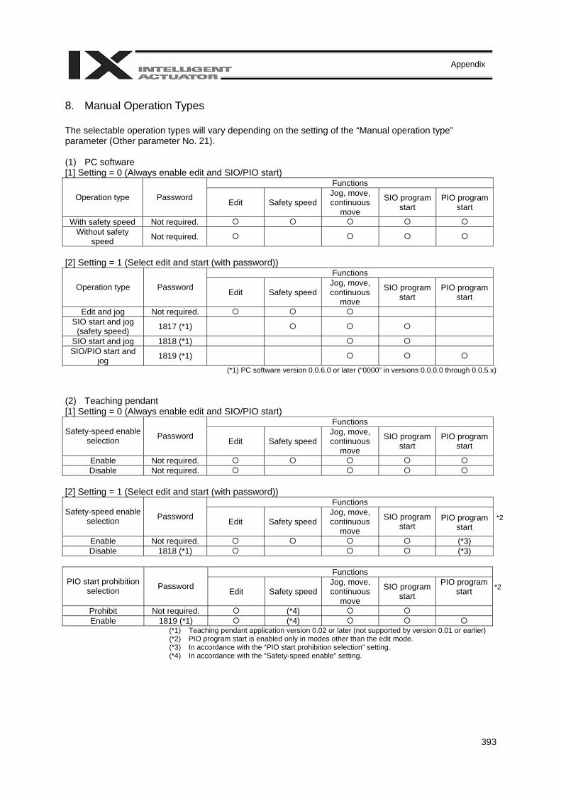
393
Appendix
8. Manual Operation Types The selectable operation types will vary depending on the setting of the “Manual operation type” parameter (Other parameter No. 21). (1) PC software [1] Setting = 0 (Always enable edit and SIO/PIO start)
Functions
Operation type Password Edit Safety speedJog, move, continuous
move
SIO program start
PIO program start
With safety speed Not required. Without safety
speed Not required.
[2] Setting = 1 (Select edit and start (with password))
Functions
Operation type Password Edit Safety speedJog, move, continuous
move
SIO program start
PIO program start
Edit and jog Not required. SIO start and jog
(safety speed) 1817 (*1)
SIO start and jog 1818 (*1) SIO/PIO start and
jog 1819 (*1)
(*1) PC software version 0.0.6.0 or later (“0000” in versions 0.0.0.0 through 0.0.5.x) (2) Teaching pendant [1] Setting = 0 (Always enable edit and SIO/PIO start)
Functions Safety-speed enable
selection Password Edit Safety speedJog, move, continuous
move
SIO program start
PIO program start
Enable Not required. Disable Not required.
[2] Setting = 1 (Select edit and start (with password))
Functions Safety-speed enable
selection Password Edit Safety speedJog, move, continuous
move
SIO program start
PIO program start
Enable Not required. (*3) Disable 1818 (*1) (*3)
Functions
PIO start prohibition selection Password Edit Safety speed
Jog, move, continuous
move
SIO program start
PIO program start
Prohibit Not required. (*4) Enable 1819 (*1) (*4)
(*1) Teaching pendant application version 0.02 or later (not supported by version 0.01 or earlier) (*2) PIO program start is enabled only in modes other than the edit mode. (*3) In accordance with the “PIO start prohibition selection” setting. (*4) In accordance with the “Safety-speed enable” setting.
*2
*2

394
Appendix
9.
Use
Exa
mpl
es o
f Key
Par
amet
ers
You
can
add
func
tions
to th
ose
avai
labl
e un
der t
he fa
ctor
y se
tting
s or
set
ded
icat
ed fu
nctio
ns to
I/O
por
ts, b
y ch
angi
ng th
e pa
ram
eter
val
ues.
Be
fore
cha
ngin
g a
para
met
er, b
e su
re to
read
the
corre
spon
ding
sec
tion
in th
e Li
st o
f Par
amet
ers.
Des
crip
tion
Act
ion
Par
amet
er s
ettin
g M
anip
ulat
ion/
oper
atio
n
Wan
t to
prev
ent e
rror
s re
latin
g to
the
stan
dard
I/O
boa
rd a
nd o
ptio
nal b
oard
s (D
evic
eNet
, CC
-Lin
k, e
tc.).
(W
ant t
o pe
rform
tria
l ope
ratio
n w
hen
boar
ds a
re n
ot w
ired,
etc
.)
I/O-b
oard
erro
r mon
itor c
an b
e di
sabl
ed
to p
reve
nt e
rrors
from
occ
urrin
g.
Set
“0” i
n th
e I/O
par
amet
er
corre
spon
ding
to th
e I/O
boa
rd w
hose
er
ror m
onito
r you
wis
h to
dis
able
. S
tand
ard
I/O (I
/O1)
: I/O
par
amet
er N
o.
10 =
0
Exp
ande
d I/O
1 (I/
O2)
: I/O
par
amet
er
No.
11
= 0
Exp
ande
d I/O
2 (I/
O3)
: I/O
par
amet
er
No.
12
= 0
Exp
ande
d I/O
3 (I/
O4)
: I/O
par
amet
er
No.
13
= 0
Set
“0” i
n I/O
par
amet
er N
os. 1
0 an
d 11
to
dis
able
err
or m
onito
r for
the
stan
dard
I/O
(I/O
1) a
nd e
xpan
ded
I/O1
(I/O
2)
boar
ds, r
espe
ctiv
ely.
N
ote:
To
oper
ate
a di
sabl
ed I/
O b
oard
, be
sur
e to
reve
rt th
e pa
ram
eter
set
ting
to “1
.”
Wan
t to
exec
ute
rest
art (
softw
are
rese
t) us
ing
an e
xter
nal i
nput
sig
nal.
Inpu
t por
t No.
1 c
an b
e se
t as
a re
star
t in
put.
I/O p
aram
eter
No.
31
= 1
Turn
ing
ON
inpu
t por
t No.
1 fo
r at l
east
1
seco
nd w
ill e
xecu
te re
star
t.
Wan
t to
exec
ute
serv
o O
N u
sing
an
exte
rnal
inpu
t sig
nal.
Inpu
t por
t No.
2 c
an b
e se
t as
a se
rvo
ON
inpu
t. I/O
par
amet
er N
o. 3
2 =
1 Se
rvo
ON
will
be e
xecu
ted
at th
e O
N
edge
of i
nput
por
t No.
2. S
ervo
OFF
will
be e
xecu
ted
at th
e O
FF e
dge.
Wan
t to
exec
ute
auto
pro
gram
sta
rt us
ing
an e
xter
nal i
nput
sig
nal.
(Und
er th
e de
faul
t set
ting,
the
spec
ified
pr
ogra
m w
ill re
star
t upo
n po
wer
ON
or
rest
art (
softw
are
rese
t) in
the
AUTO
m
ode.
) (M
ore
step
s w
ill be
requ
ired
to
exec
ute
auto
pro
gram
sta
rt.)
Inpu
t por
t No.
3 c
an b
e se
t as
an a
uto
prog
ram
sta
rt in
put.
I/O p
aram
eter
No.
33
= 2
The
spec
ified
pro
gram
will
sta
rt at
the
ON
edg
e of
inpu
t por
t No.
3. T
he
prog
ram
will
be a
borte
d at
the
OFF
ed
ge.
Wan
t to
exec
ute
paus
e us
ing
an
exte
rnal
inpu
t sig
nal.
Inpu
t por
t No.
6 c
an b
e se
t as
a pa
use
inpu
t. In
put p
ort N
o. 5
can
be
set a
s a
paus
e re
set i
nput
.
I/O p
aram
eter
No.
36
= 1
I/O p
aram
eter
No.
35
= 1
Turn
ing
OFF
inpu
t por
t No.
6 w
ill
exec
ute
paus
e. P
ause
will
be
rese
t at
the
ON
edg
e of
inpu
t por
t No.
5 a
fter
turn
ing
ON
inpu
t por
t No.
6.
(Inpu
t por
t No.
6 is
alw
ays
ON
.) W
ant t
o re
set e
rror
s us
ing
an e
xter
nal
inpu
t sig
nal (
erro
rs o
f ope
ratio
n-ca
ncel
latio
n le
vel o
r low
er).
Inpu
t por
t No.
13
can
be s
et a
s an
erro
r re
set i
nput
. I/O
par
amet
er N
o. 4
3 =
2 E
rrors
will
be re
set a
t the
ON
edg
e of
in
put p
ort N
o 13
.
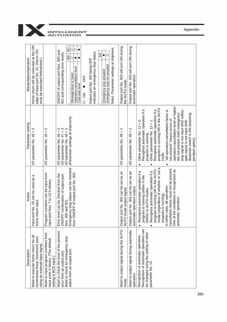
395
Appendix
D
escr
iptio
n A
ctio
n P
aram
eter
set
ting
Man
ipul
atio
n/op
erat
ion
Wan
t to
exec
ute
hom
e re
turn
for a
ll in
crem
enta
l lin
ear m
ovem
ent a
xes
usin
g an
ext
erna
l inp
ut s
igna
l.
Inpu
t por
t No.
15
can
be u
sed
as a
ho
me
retu
rn in
put.
I/O p
aram
eter
No.
45
= 2
Hom
e re
turn
will
be
exec
uted
at t
he O
N
edge
of i
nput
por
t No.
15.
(Ser
vo O
N
mus
t be
exec
uted
bef
oreh
and.
) W
ant t
o in
put p
rogr
am n
umbe
rs fr
om
inpu
t por
ts in
bin
ary.
(The
def
ault
setti
ng is
BC
D in
put.)
Pro
gram
num
bers
can
be
inpu
t fro
m
inpu
t por
t Nos
. 7 to
13
in b
inar
y.
I/O p
aram
eter
No.
30
= 2
Wan
t to
chec
k th
e le
vel o
f the
pre
sent
er
ror f
rom
an
outp
ut p
ort.
Wan
t to
chec
k fo
r em
erge
ncy
stop
st
atus
from
an
outp
ut p
ort.
Erro
r lev
el c
an b
e ch
ecke
d fro
m th
e O
N/O
FF c
ombi
natio
n of
out
put p
ort
Nos
. 300
and
301
. E
mer
genc
y st
op s
tatu
s ca
n be
che
cked
fro
m O
N/O
FF o
f out
put p
ort N
o. 3
02.
I/O p
aram
eter
No.
46
= 2
I/O p
aram
eter
No.
47
= 3
I/O p
aram
eter
No.
48
= 2
(Par
amet
er s
ettin
gs a
t shi
pmen
t)
ON
/OFF
of o
utpu
t por
t Nos
. 300
and
30
1 an
d co
rresp
ondi
ng e
rror l
evel
s
300
301
Mes
sage
leve
l or l
ower
O
pera
tion-
canc
ella
tion
leve
l
C
old-
star
t lev
el
: O
N
: O
FF
Out
put p
ort N
o. 3
02 b
eing
OFF
in
dica
tes
an e
mer
genc
y st
op s
tatu
s.
30
2 E
mer
genc
y st
op a
ctua
ted
E
mer
genc
y st
op n
ot a
ctua
ted
Not
e) P
aram
eter
set
tings
at s
hipm
ent
W
ant t
o ou
tput
sig
nal d
urin
g th
e A
UTO
m
ode.
O
utpu
t por
t No.
303
can
be
set a
s an
A
UTO
mod
e ou
tput
sig
nal.
I/O p
aram
eter
No.
49
= 1
Out
put p
ort N
o. 3
03 w
ill tu
rn O
N d
urin
g th
e A
UTO
mod
e.
Wan
t to
outp
ut s
igna
l dur
ing
auto
mat
ic
oper
atio
n.
Out
put p
ort N
o. 3
03 c
an b
e se
t as
an
auto
mat
ic o
pera
tion
outp
ut.
I/O p
aram
eter
No.
49
= 2
Out
put p
ort N
o. 3
03 w
ill tu
rn O
N d
urin
g au
tom
atic
ope
ratio
n.
Rec
ogni
tion
of a
utom
atic
ope
ratio
n:
Rec
ogni
tion
of a
utom
atic
ope
ratio
n ca
n be
cha
nged
usi
ng th
e se
tting
of o
ther
pa
ram
eter
No.
12.
• R
ecog
nize
aut
omat
ic o
pera
tion
if a
prog
ram
is ru
nnin
g (e
ither
in th
e M
AN
U o
r AU
TO m
ode)
. •
Rec
ogni
ze a
utom
atic
ope
ratio
n if
a pr
ogra
m is
runn
ing
OR
in th
e A
UTO
m
ode
(reg
ardl
ess
of w
heth
er o
r not
a
prog
ram
is ru
nnin
g).
In e
ither
cas
e, a
ll-op
erat
ion-
canc
ella
tion
fact
or m
ust n
ot b
e pr
esen
t.O
ne o
f the
con
ditio
ns is
reco
gniz
ed a
s au
tom
atic
ope
ratio
n.
• O
ther
par
amet
er N
o. 1
2 =
0 R
ecog
nize
aut
omat
ic o
pera
tion
if a
prog
ram
is ru
nnin
g.
• O
ther
par
amet
er N
o. 1
2 =
1 R
ecog
nize
aut
omat
ic o
pera
tion
if a
prog
ram
is ru
nnin
g O
R in
the
AU
TO
mod
e.
• “A
ll-op
erat
ion-
canc
ella
tion
fact
or is
no
t pre
sent
” mea
ns e
rror
s of
op
erat
ion-
canc
ella
tion
leve
l or h
ighe
r ar
e no
t pre
sent
AN
D e
mer
genc
y-st
op s
igna
l is
not i
nput
AN
D s
afet
y-ga
te s
igna
l is
not i
nput
AN
D
dead
man
sw
itch
is O
N (t
each
ing-
pend
ant o
ptio
n).
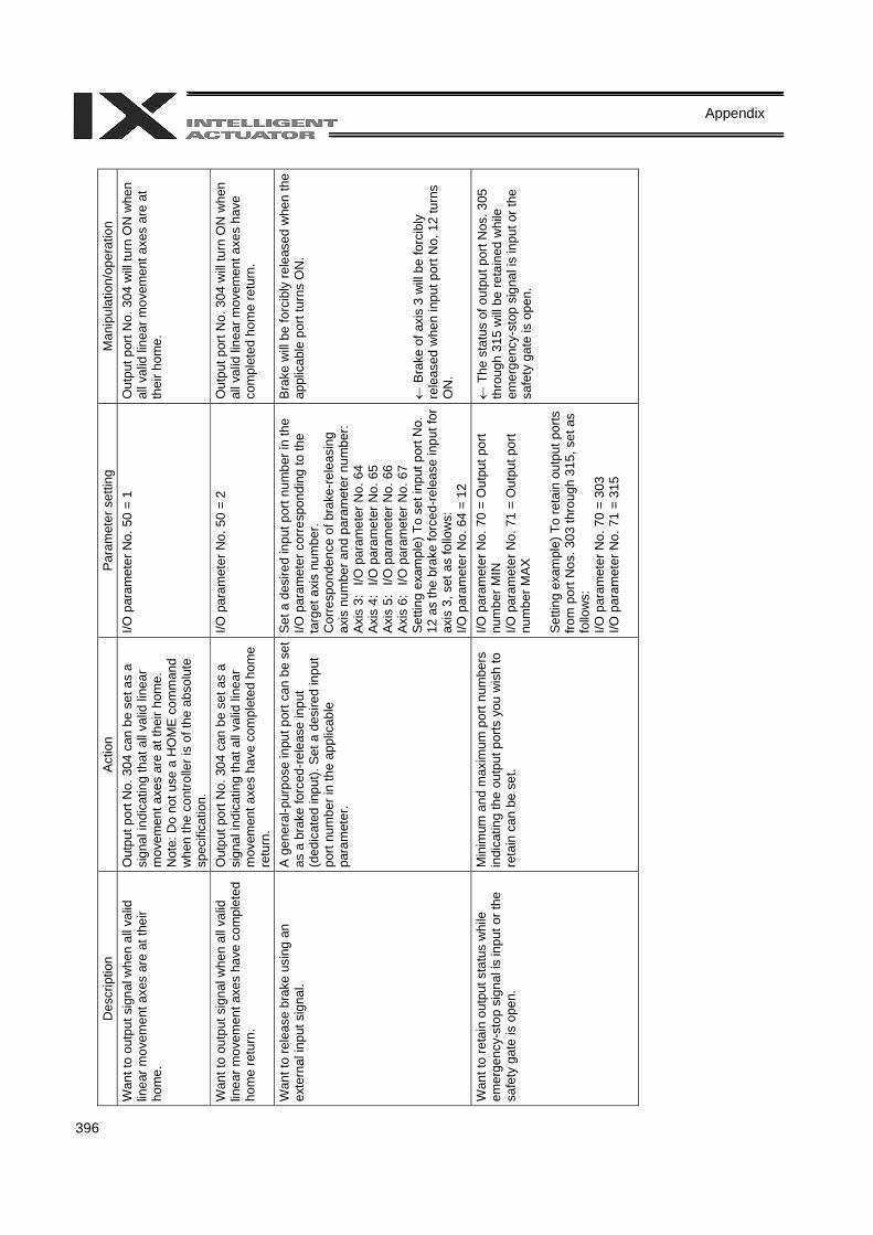
396
Appendix
D
escr
iptio
n A
ctio
n P
aram
eter
set
ting
Man
ipul
atio
n/op
erat
ion
Wan
t to
outp
ut s
igna
l whe
n al
l val
id
linea
r mov
emen
t axe
s ar
e at
thei
r ho
me.
Out
put p
ort N
o. 3
04 c
an b
e se
t as
a si
gnal
indi
catin
g th
at a
ll va
lid li
near
m
ovem
ent a
xes
are
at th
eir h
ome.
N
ote:
Do
not u
se a
HO
ME
com
man
d w
hen
the
cont
rolle
r is
of th
e ab
solu
te
spec
ifica
tion.
I/O p
aram
eter
No.
50
= 1
Out
put p
ort N
o. 3
04 w
ill tu
rn O
N w
hen
all v
alid
line
ar m
ovem
ent a
xes
are
at
thei
r hom
e.
Wan
t to
outp
ut s
igna
l whe
n al
l val
id
linea
r mov
emen
t axe
s ha
ve c
ompl
eted
ho
me
retu
rn.
Out
put p
ort N
o. 3
04 c
an b
e se
t as
a si
gnal
indi
catin
g th
at a
ll va
lid li
near
m
ovem
ent a
xes
have
com
plet
ed h
ome
retu
rn.
I/O p
aram
eter
No.
50
= 2
Out
put p
ort N
o. 3
04 w
ill tu
rn O
N w
hen
all v
alid
line
ar m
ovem
ent a
xes
have
co
mpl
eted
hom
e re
turn
.
Wan
t to
rele
ase
brak
e us
ing
an
exte
rnal
inpu
t sig
nal.
A g
ener
al-p
urpo
se in
put p
ort c
an b
e se
t as
a b
rake
forc
ed-re
leas
e in
put
(ded
icat
ed in
put).
Set
a d
esire
d in
put
port
num
ber i
n th
e ap
plic
able
pa
ram
eter
.
Set
a d
esire
d in
put p
ort n
umbe
r in
the
I/O p
aram
eter
cor
resp
ondi
ng to
the
targ
et a
xis
num
ber.
Cor
resp
onde
nce
of b
rake
-rel
easi
ng
axis
num
ber a
nd p
aram
eter
num
ber:
Ax
is 3
: I/O
par
amet
er N
o. 6
4 Ax
is 4
: I/O
par
amet
er N
o. 6
5 Ax
is 5
: I/O
par
amet
er N
o. 6
6 Ax
is 6
: I/O
par
amet
er N
o. 6
7 S
ettin
g ex
ampl
e) T
o se
t inp
ut p
ort N
o.
12 a
s th
e br
ake
forc
ed-r
elea
se in
put f
or
axis
3, s
et a
s fo
llow
s:
I/O p
aram
eter
No.
64
= 12
Bra
ke w
ill b
e fo
rcib
ly re
leas
ed w
hen
the
appl
icab
le p
ort t
urns
ON
. ←
Bra
ke o
f axi
s 3
will
be fo
rcib
ly
rele
ased
whe
n in
put p
ort N
o. 1
2 tu
rns
ON
.
Wan
t to
reta
in o
utpu
t sta
tus
whi
le
emer
genc
y-st
op s
igna
l is
inpu
t or t
he
safe
ty g
ate
is o
pen.
Min
imum
and
max
imum
por
t num
bers
in
dica
ting
the
outp
ut p
orts
you
wis
h to
re
tain
can
be
set.
I/O p
aram
eter
No.
70
= O
utpu
t por
t nu
mbe
r MIN
I/O
par
amet
er N
o. 7
1 =
Out
put p
ort
num
ber M
AX
S
ettin
g ex
ampl
e) T
o re
tain
out
put p
orts
fro
m p
ort N
os. 3
03 th
roug
h 31
5, s
et a
s fo
llow
s:
I/O p
aram
eter
No.
70
= 30
3 I/O
par
amet
er N
o. 7
1 =
315
← T
he s
tatu
s of
out
put p
ort N
os. 3
05
thro
ugh
315
will
be
reta
ined
whi
le
emer
genc
y-st
op s
igna
l is
inpu
t or t
he
safe
ty g
ate
is o
pen.
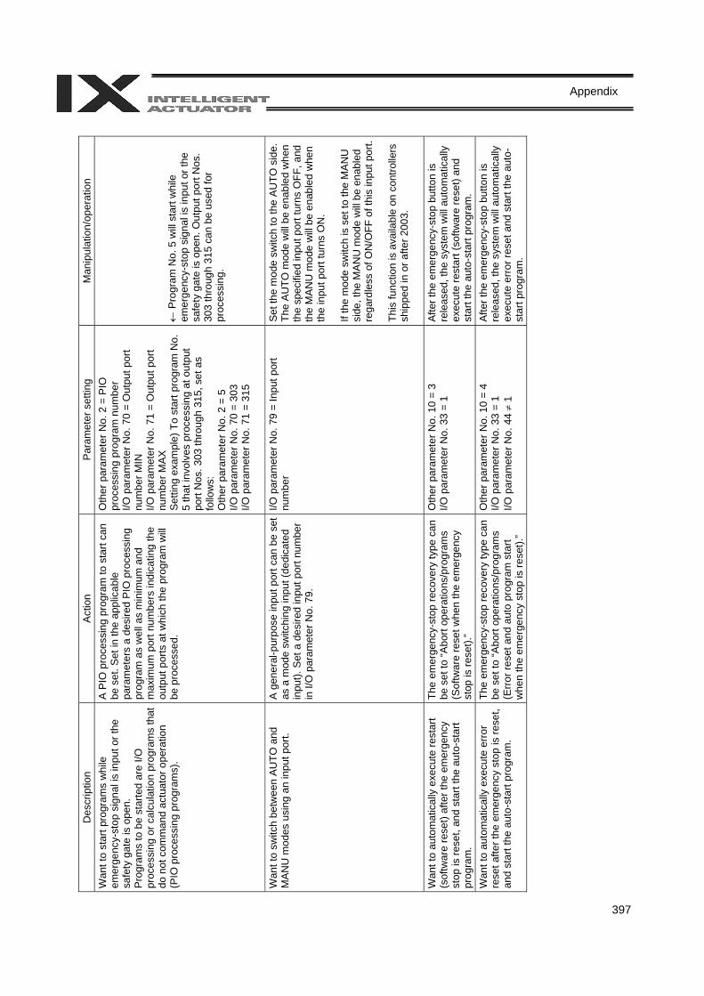
397
Appendix
D
escr
iptio
n A
ctio
n P
aram
eter
set
ting
Man
ipul
atio
n/op
erat
ion
Wan
t to
star
t pro
gram
s w
hile
em
erge
ncy-
stop
sig
nal i
s in
put o
r the
sa
fety
gat
e is
ope
n.
Pro
gram
s to
be
star
ted
are
I/O
proc
essi
ng o
r cal
cula
tion
prog
ram
s th
at
do n
ot c
omm
and
actu
ator
ope
ratio
n (P
IO p
roce
ssin
g pr
ogra
ms)
.
A P
IO p
roce
ssin
g pr
ogra
m to
sta
rt ca
n be
set
. Set
in th
e ap
plic
able
pa
ram
eter
s a
desi
red
PIO
pro
cess
ing
prog
ram
as
wel
l as
min
imum
and
m
axim
um p
ort n
umbe
rs in
dica
ting
the
outp
ut p
orts
at w
hich
the
prog
ram
will
be p
roce
ssed
.
Oth
er p
aram
eter
No.
2 =
PIO
pr
oces
sing
pro
gram
num
ber
I/O p
aram
eter
No.
70
= O
utpu
t por
t nu
mbe
r MIN
I/O
par
amet
er N
o. 7
1 =
Out
put p
ort
num
ber M
AX
S
ettin
g ex
ampl
e) T
o st
art p
rogr
am N
o.
5 th
at in
volv
es p
roce
ssin
g at
out
put
port
Nos
. 303
thro
ugh
315,
set
as
follo
ws:
O
ther
par
amet
er N
o. 2
= 5
I/O
par
amet
er N
o. 7
0 =
303
I/O p
aram
eter
No.
71
= 31
5
← P
rogr
am N
o. 5
will
star
t whi
le
emer
genc
y-st
op s
igna
l is
inpu
t or t
he
safe
ty g
ate
is o
pen.
Out
put p
ort N
os.
303
thro
ugh
315
can
be u
sed
for
proc
essi
ng.
Wan
t to
switc
h be
twee
n A
UTO
and
M
AN
U m
odes
usi
ng a
n in
put p
ort.
A g
ener
al-p
urpo
se in
put p
ort c
an b
e se
t as
a m
ode
switc
hing
inpu
t (de
dica
ted
inpu
t). S
et a
des
ired
inpu
t por
t num
ber
in I/
O p
aram
eter
No.
79.
I/O p
aram
eter
No.
79
= In
put p
ort
num
ber
Set t
he m
ode
switc
h to
the
AUTO
sid
e.
The
AU
TO m
ode
will
be e
nabl
ed w
hen
the
spec
ified
inpu
t por
t tur
ns O
FF, a
nd
the
MA
NU
mod
e w
ill be
ena
bled
whe
n th
e in
put p
ort t
urns
ON
. If
the
mod
e sw
itch
is s
et to
the
MA
NU
si
de, t
he M
AN
U m
ode
will
be e
nabl
ed
rega
rdle
ss o
f ON
/OFF
of t
his
inpu
t por
t. Th
is fu
nctio
n is
ava
ilabl
e on
con
trolle
rs
ship
ped
in o
r afte
r 200
3.
W
ant t
o au
tom
atic
ally
exe
cute
rest
art
(sof
twar
e re
set)
afte
r the
em
erge
ncy
stop
is re
set,
and
star
t the
aut
o-st
art
prog
ram
.
The
emer
genc
y-st
op re
cove
ry ty
pe c
an
be s
et to
“Abo
rt op
erat
ions
/pro
gram
s (S
oftw
are
rese
t whe
n th
e em
erge
ncy
stop
is re
set).
”
Oth
er p
aram
eter
No.
10
= 3
I/O p
aram
eter
No.
33
= 1
Afte
r the
em
erge
ncy-
stop
but
ton
is
rele
ased
, the
sys
tem
will
aut
omat
ical
ly
exec
ute
rest
art (
softw
are
rese
t) an
d st
art t
he a
uto-
star
t pro
gram
. W
ant t
o au
tom
atic
ally
exe
cute
err
or
rese
t afte
r the
em
erge
ncy
stop
is re
set,
and
star
t the
aut
o-st
art p
rogr
am.
The
emer
genc
y-st
op re
cove
ry ty
pe c
an
be s
et to
“Abo
rt op
erat
ions
/pro
gram
s (E
rror
rese
t and
aut
o pr
ogra
m s
tart
whe
n th
e em
erge
ncy
stop
is re
set).
”
Oth
er p
aram
eter
No.
10
= 4
I/O p
aram
eter
No.
33
= 1
I/O p
aram
eter
No.
44 ≠
1
Afte
r the
em
erge
ncy-
stop
but
ton
is
rele
ased
, the
sys
tem
will
aut
omat
ical
ly
exec
ute
erro
r res
et a
nd s
tart
the
auto
-st
art p
rogr
am.
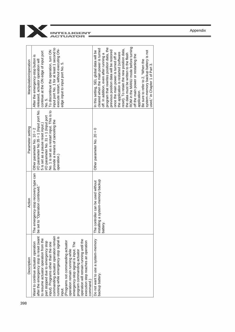
398
Appendix
D
escr
iptio
n A
ctio
n P
aram
eter
set
ting
Man
ipul
atio
n/op
erat
ion
Wan
t to
cont
inue
act
uato
r ope
ratio
n af
ter t
he e
mer
genc
y st
op is
rese
t (w
ant
to re
sum
e ac
tuat
or o
pera
tion
from
the
part
stop
ped
due
to e
mer
genc
y st
op
inpu
t). P
rogr
ams
othe
r tha
n th
e on
e co
mm
andi
ng a
ctua
tor o
pera
tion
rem
ain
runn
ing
whi
le e
mer
genc
y-st
op s
igna
l is
inpu
t. (P
rogr
ams
not c
omm
andi
ng a
ctua
tor
oper
atio
n re
mai
n ru
nnin
g w
hile
em
erge
ncy-
stop
sig
nal i
s in
put.
The
prog
ram
com
man
ding
act
uato
r op
erat
ion
will
rem
ain
runn
ing
until
the
exec
utio
n st
ep re
ache
s an
ope
ratio
n co
mm
and.
)
The
emer
genc
y-st
op re
cove
ry ty
pe c
an
be s
et to
“Ope
ratio
n co
ntin
ued.
” O
ther
par
amet
er N
o. 1
0 =
2 I/O
par
amet
er N
o 35
= 1
(Inp
ut p
ort N
o.
5 is
set
as
a pa
use
rese
t inp
ut.)
I/O p
aram
eter
No.
31
= 1
(Inpu
t por
t N
o. 1
is s
et a
s a
rest
art i
nput
. Thi
s is
to
prov
ide
a m
eans
of c
ance
ling
the
oper
atio
n.)
Afte
r the
em
erge
ncy-
stop
but
ton
is
rele
ased
, act
uato
r ope
ratio
n w
ill co
ntin
ue a
t the
ON
edg
e of
inpu
t por
t N
o. 5
. To
dis
cont
inue
the
oper
atio
n, tu
rn O
N
inpu
t por
t No.
1 fo
r at l
east
1 s
econ
d to
ex
ecut
e re
star
t, w
ithou
t exe
cutin
g O
N-
edge
inpu
t to
inpu
t por
t No.
5.
Do
not w
ant t
o us
e a
syst
em-m
emor
y ba
ckup
bat
tery
. Th
e co
ntro
ller c
an b
e us
ed w
ithou
t in
stal
ling
a sy
stem
-mem
ory
back
up
batte
ry.
Oth
er p
aram
eter
No.
20
= 0
In th
is s
ettin
g, S
EL
glob
al d
ata
will
be
clea
red
whe
n th
e m
ain
pow
er is
turn
ed
off.
In a
dditi
on, e
ven
afte
r run
ning
a
prog
ram
that
rew
rites
pos
ition
dat
a, th
e pr
evio
us p
ositi
on d
ata
will
be re
stor
ed
once
the
mai
n po
wer
is tu
rned
off
or
the
appl
icat
ion
is re
star
ted
(sof
twar
e re
set).
To
reta
in th
e ne
w p
ositi
on d
ata,
th
e da
ta m
ust b
e w
ritte
n to
the
flash
R
OM
in th
e M
ANU
mod
e be
fore
turn
ing
off t
he m
ain
pow
er o
r res
tarti
ng th
e ap
plic
atio
n.
Be s
ure
to re
fer t
o 2,
“Whe
n th
e sy
stem
-mem
ory
back
up b
atte
ry is
not
us
ed,”
in C
hapt
er 1
of P
art 3
.
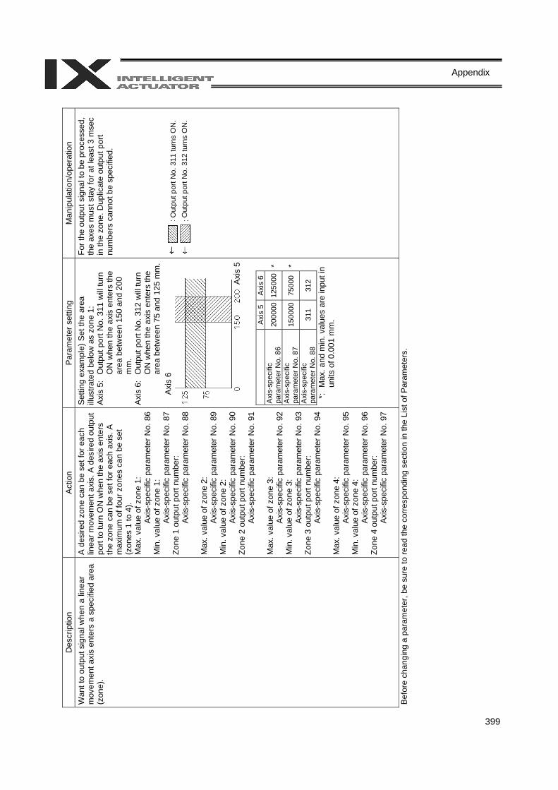
399
Appendix
D
escr
iptio
n A
ctio
n P
aram
eter
set
ting
Man
ipul
atio
n/op
erat
ion
Wan
t to
outp
ut s
igna
l whe
n a
linea
r m
ovem
ent a
xis
ente
rs a
spe
cifie
d ar
ea
(zon
e).
A d
esire
d zo
ne c
an b
e se
t for
eac
h lin
ear m
ovem
ent a
xis.
A d
esire
d ou
tput
po
rt to
turn
ON
whe
n th
e ax
is e
nter
s th
e zo
ne c
an b
e se
t for
eac
h ax
is. A
m
axim
um o
f fou
r zon
es c
an b
e se
t (z
ones
1 to
4).
Max
. val
ue o
f zon
e 1:
Ax
is-s
peci
fic p
aram
eter
No.
86
Min
. val
ue o
f zon
e 1:
Ax
is-s
peci
fic p
aram
eter
No.
87
Zone
1 o
utpu
t por
t num
ber:
Axis
-spe
cific
par
amet
er N
o. 8
8 M
ax. v
alue
of z
one
2:
Axis
-spe
cific
par
amet
er N
o. 8
9M
in. v
alue
of z
one
2:
Axis
-spe
cific
par
amet
er N
o. 9
0Zo
ne 2
out
put p
ort n
umbe
r: Ax
is-s
peci
fic p
aram
eter
No.
91
Max
. val
ue o
f zon
e 3:
Ax
is-s
peci
fic p
aram
eter
No.
92
Min
. val
ue o
f zon
e 3:
Ax
is-s
peci
fic p
aram
eter
No.
93
Zone
3 o
utpu
t por
t num
ber:
Axis
-spe
cific
par
amet
er N
o. 9
4 M
ax. v
alue
of z
one
4:
Axis
-spe
cific
par
amet
er N
o. 9
5M
in. v
alue
of z
one
4:
Axis
-spe
cific
par
amet
er N
o. 9
6Zo
ne 4
out
put p
ort n
umbe
r: Ax
is-s
peci
fic p
aram
eter
No.
97
Set
ting
exam
ple)
Set
the
area
illu
stra
ted
belo
w a
s zo
ne 1
: Ax
is 5
: O
utpu
t por
t No.
311
will
turn
O
N w
hen
the
axis
ent
ers
the
area
bet
wee
n 15
0 an
d 20
0 m
m.
Axis
6:
Out
put p
ort N
o. 3
12 w
ill tu
rn
ON
whe
n th
e ax
is e
nter
s th
e ar
ea b
etw
een
75 a
nd 1
25 m
m.
Axi
s 5
Axis
6
A
xis-
spec
ific
para
met
er N
o. 8
6 20
0000
1250
00*
Axi
s-sp
ecifi
c pa
ram
eter
No.
87
1500
0075
000
*
Axi
s-sp
ecifi
c pa
ram
eter
No.
88
311
312
*:
Max
. and
min
. val
ues
are
inpu
t in
units
of 0
.001
mm
.
For t
he o
utpu
t sig
nal t
o be
pro
cess
ed,
the
axes
mus
t sta
y fo
r at l
east
3 m
sec
in th
e zo
ne. D
uplic
ate
outp
ut p
ort
num
bers
can
not b
e sp
ecifi
ed.
Bef
ore
chan
ging
a p
aram
eter
, be
sure
to re
ad th
e co
rres
pond
ing
sect
ion
in th
e Li
st o
f Par
amet
ers.
Axi
s 5
Axis
6O
utpu
t por
t No.
311
turn
s O
N.
Out
put p
ort N
o. 3
12 tu
rns
ON
.
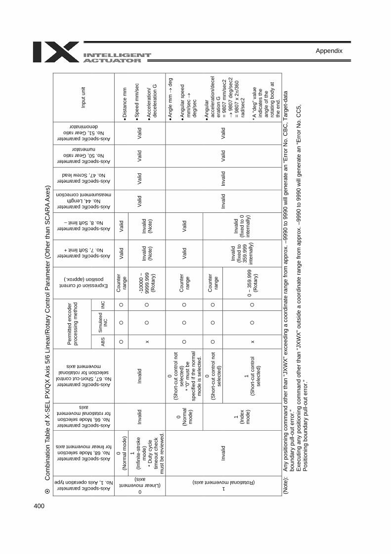
400
Appendix
Com
bina
tion
Tabl
e of
X-S
EL
PX/Q
X Ax
is 5
/6 L
inea
r/Rot
ary
Con
trol P
aram
eter
(Oth
er th
an S
CAR
A Ax
es)
Per
mitt
ed e
ncod
er
proc
essi
ng m
etho
d
Axis-specific parameter No. 1, Axis operation type
Axis-specific parameter No. 68, Mode selection
for linear movement axis
Axis-specific parameter No. 66, Mode selection for rotational movement
axis
Axis-specific parameter No. 67, Short-cut control selection for rotational
movement axis
AB
SSi
mul
ated
IN
C
INC
Expression of current position (approx.)
Axis-specific parameter No. 7, Soft limit +
Axis-specific parameter No. 8, Soft limit –
Axis-specific parameter No. 44, Length
measurement correction
Axis-specific parameter No. 47, Screw lead
Axis-specific parameter No. 50, Gear ratio
numerator
Axis-specific parameter No. 51, Gear ratio
denominator
Inpu
t uni
t
0 (N
orm
al m
ode)
Cou
nter
ra
nge
Valid
V
alid
0 (Linear movement
axis)
1 (In
finite
-stro
ke
mod
e)
* Dut
y cy
cle
timeo
ut c
heck
m
ust b
e re
view
ed.
Inva
lid
Inva
lid
x
-1
0000
~
9999
.999
(R
otar
y)
Inva
lid
(Not
e)
Inva
lid
(Not
e)
Valid
V
alid
V
alid
Va
lid
• Dis
tanc
e m
m
• Spe
ed m
m/s
ec
• Acc
eler
atio
n/
dece
lera
tion
G
0 (N
orm
al
mod
e)
0 (S
hort-
cut c
ontro
l not
se
lect
ed)
* “0
” mus
t be
spec
ified
if th
e no
rmal
m
ode
is s
elec
ted.
C
ount
er
rang
e Va
lid
Val
id
0 (S
hort-
cut c
ontro
l not
se
lect
ed)
C
ount
er
rang
e
1 (Rotational movement axis)
Inva
lid
1 (In
dex
mod
e)
1 (S
hort-
cut c
ontro
l se
lect
ed)
x
0
~ 35
9.99
9(R
otar
y)
Inva
lid
(fixe
d to
35
9.99
9 in
tern
ally
)
Inva
lid
(fixe
d to
0
inte
rnal
ly)
Inva
lid
Inva
lid
Val
id
Valid
• Ang
le m
m →
deg
• A
ngul
ar s
peed
m
m/s
ec →
de
g/se
c • A
ngul
ar
acce
lera
tion/
dece
ler
atio
n G
=
980
7 m
m/s
ec2
→ 9
807
deg/
sec2
=
9807
x 2π/
360
rad/
sec2
* A
“deg
” val
ue
indi
cate
s th
e an
gle
of th
e ro
tatin
g bo
dy a
t th
e en
d.
(Not
e):
Any
pos
ition
ing
com
man
d ot
her t
han
“JX
WX
” exc
eedi
ng a
coo
rdin
ate
rang
e fro
m a
ppro
x. –
9990
to 9
990
will
gene
rate
an
“Err
or N
o. C
BC
, Tar
get-d
ata
boun
dary
pul
l-out
err
or.”
Exec
utin
g an
y po
sitio
ning
com
man
d ot
her t
han
“JXW
X” o
utsi
de a
coo
rdin
ate
rang
e fro
m a
ppro
x. –
9990
to 9
990
will
gene
rate
an
“Err
or N
o. C
C5,
P
ositi
onin
g bo
unda
ry p
ull-o
ut e
rror
.”
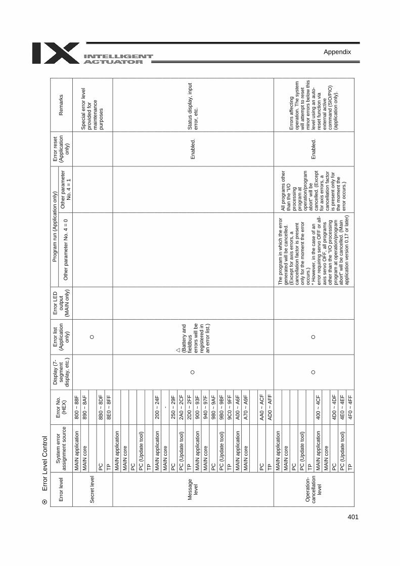
401
Appendix
E
rror
Lev
el C
ontro
l Pr
ogra
m ru
n (A
pplic
atio
n on
ly)
Erro
r lev
el
Sys
tem
err
or
assi
gnm
ent s
ourc
e E
rror N
o.
(HEX
)
Dis
play
(7-
segm
ent
disp
lay,
etc
.)
Erro
r lis
t (A
pplic
atio
n on
ly)
Erro
r LED
ou
tput
(M
AIN
onl
y)O
ther
par
amet
er N
o. 4
= 0
O
ther
par
amet
er
No.
4 =
1
Err
or re
set
(App
licat
ion
only
) R
emar
ks
MA
IN a
pplic
atio
n 80
0 ~
88F
MA
IN c
ore
890
~ 8A
F
PC
8B
0 ~
8DF
Sec
ret l
evel
TP
8E0
~ 8F
F
Spe
cial
err
or le
vel
prov
ided
for
mai
nten
ance
pu
rpos
es
MA
IN a
pplic
atio
n
MA
IN c
ore
PC
PC
(Upd
ate
tool
)
TP
M
AIN
app
licat
ion
200
~ 24
F M
AIN
cor
e -
PC
25
0 ~
29F
PC
(Upd
ate
tool
) 2A
0 ~
2CF
TP
2D0
~ 2F
F M
AIN
app
licat
ion
900
~ 93
F M
AIN
cor
e 94
0 ~
97F
PC
98
0 ~
9AF
PC
(Upd
ate
tool
) 9B
0 ~
9BF
TP
9C0
~ 9F
F M
AIN
app
licat
ion
A00
~ A
6F
MA
IN c
ore
A70
~ A
9F
PC
AA0
~ A
CF
Mes
sage
le
vel
TP
AD0
~ A
FF
(B
atte
ry a
nd
field
bus
erro
rs w
ill b
e re
gist
ered
in
an e
rror l
ist.)
E
nabl
ed.
Sta
tus
disp
lay,
inpu
t er
ror,
etc.
MA
IN a
pplic
atio
n
MA
IN c
ore
PC
PC
(Upd
ate
tool
)
TP
M
AIN
app
licat
ion
400
~ 4C
F M
AIN
cor
e
PC
4D
0 ~
4DF
PC
(Upd
ate
tool
) 4E
0 ~
4EF
Ope
ratio
n-ca
ncel
latio
n le
vel
TP
4F0
~ 4F
F
The
prog
ram
in w
hich
the
erro
r ge
nera
ted
will
be
canc
elle
d.
(Exc
ept f
or a
xis
erro
rs, a
ca
ncel
latio
n fa
ctor
is p
rese
nt
only
for t
he m
omen
t the
erro
r oc
curs
.) * H
owev
er, i
n th
e ca
se o
f an
erro
r req
uirin
g se
rvo
OFF
or a
ll-ax
is s
ervo
OFF
, all
prog
ram
s ot
her t
han
the
“I/O
pro
cess
ing
prog
ram
at o
pera
tion/
prog
ram
ab
ort”
will
be
canc
elle
d. (M
ain
appl
icat
ion
vers
ion
0.17
or l
ater
)
All
prog
ram
s ot
her
than
the
“I/O
pr
oces
sing
pr
ogra
m a
t op
erat
ion/
prog
ram
ab
ort”
will
be
canc
elle
d. (E
xcep
t fo
r axi
s er
rors
, a
canc
ella
tion
fact
or
is p
rese
nt o
nly
for
the
mom
ent t
he
erro
r occ
urs.
)
Ena
bled
.
Err
ors
affe
ctin
g op
erat
ion.
The
sys
tem
w
ill a
ttem
pt to
rese
t m
inor
err
ors
belo
w th
is
leve
l usi
ng a
n au
to-
rese
t fun
ctio
n vi
a ex
tern
al a
ctiv
e co
mm
and
(SIO
/PIO
) (a
pplic
atio
n on
ly).
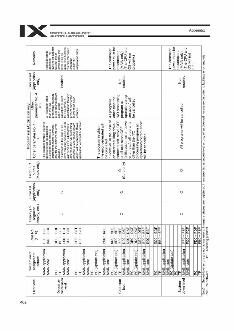
402
Appendix
P
rogr
am ru
n (A
pplic
atio
n on
ly)
Erro
r lev
el
Sys
tem
err
or
assi
gnm
ent
sour
ce
Erro
r No.
(H
EX
)
Dis
play
(7-
segm
ent
disp
lay,
etc
.)
Erro
r lis
t (A
pplic
atio
n on
ly)
Err
or L
ED
outp
ut
(MAI
N o
nly)
Oth
er p
aram
eter
No.
4 =
0
Oth
er
para
met
er N
o. 4
=
1
Erro
r res
et
(App
licat
ion
only
) R
emar
ks
MA
IN a
pplic
atio
n B
00 ~
B9F
M
AIN
cor
e BA
0 ~
BBF
PC
B
C0
~ B
DF
TP
BE
0 ~
BFF
M
AIN
app
licat
ion
C00
~ C
CF
MAI
N c
ore
CD
0 ~
CD
F
PC
C
E0 ~
CE
F
Ope
ratio
n-ca
ncel
latio
n le
vel
TP
CF0
~ C
FF
The
prog
ram
in w
hich
the
erro
r ge
nera
ted
will
be
canc
elle
d.
(Exc
ept f
or a
xis
erro
rs, a
ca
ncel
latio
n fa
ctor
is p
rese
nt
only
for t
he m
omen
t the
err
or
occu
rs.)
* H
owev
er, i
n th
e ca
se o
f an
erro
r req
uirin
g se
rvo
OFF
or a
ll-ax
is s
ervo
OFF
, all
prog
ram
s ot
her t
han
the
“I/O
pro
cess
ing
prog
ram
at o
pera
tion/
prog
ram
ab
ort”
will
be
canc
elle
d. (M
ain
appl
icat
ion
vers
ion
0.17
or l
ater
)
All
prog
ram
s ot
her
than
the
“I/O
pr
oces
sing
pro
gram
at
ope
ratio
n/pr
ogra
m
abor
t” w
ill b
e ca
ncel
led.
(Exc
ept
for a
xis
erro
rs, a
ca
ncel
latio
n fa
ctor
is
pres
ent o
nly
for t
he
mom
ent t
he e
rror
occu
rs.)
Ena
bled
.
Erro
rs a
ffect
ing
oper
atio
n. T
he
syst
em w
ill a
ttem
pt
to re
set m
inor
er
rors
bel
ow th
is
leve
l usi
ng a
n au
to-r
eset
func
tion
via
exte
rnal
act
ive
com
man
d (S
IO/P
IO)
(app
licat
ion
only
).
MA
IN a
pplic
atio
n
MAI
N c
ore
PC
PC
(Upd
ate
tool
)
TP
M
AIN
app
licat
ion
600
~ 6C
F M
AIN
cor
e -
PC
6D0
~ 6D
F P
C (U
pdat
e to
ol)
6E0
~ 6E
F TP
6F
0 ~
6FF
MA
IN a
pplic
atio
n D
00 ~
D8F
M
AIN
cor
e D
90 ~
DA
F PC
D
B0 ~
DC
F P
C (U
pdat
e to
ol)
DD
0 ~
DD
FTP
D
E0 ~
DFF
M
AIN
app
licat
ion
E00
~ E
8F
MAI
N c
ore
E90
~ E
BF
PC
EC
0 ~
ED
F
Col
d-st
art
leve
l
TP
EE
0 ~
EFF
(C
ore
only
)
The
prog
ram
in w
hich
th
e er
ror g
ener
ated
will
be
can
celle
d.
* H
owev
er, i
n th
e ca
se o
f an
erro
r req
uirin
g dr
ive-
sour
ce c
utof
f, se
rvo
OFF
or
all-
axis
ser
vo O
FF
(initi
aliz
atio
n er
ror,
pow
er
erro
r, et
c.),
all p
rogr
ams
othe
r tha
n th
e “I/
O
proc
essi
ng p
rogr
am a
t op
erat
ion/
prog
ram
abo
rt”
will
be
canc
elle
d.
All
prog
ram
s ot
her t
han
the
“I/O
pro
cess
ing
prog
ram
at
oper
atio
n/pr
ogr
am a
bort”
will
be c
ance
lled
Not
en
able
d.
The
cont
rolle
r po
wer
mus
t be
reco
nnec
ted
(MAI
N o
nly)
. (T
he C
PU a
nd
OS
will
run
prop
erly
.)
MA
IN a
pplic
atio
n
MA
IN c
ore
- P
C (U
pdat
e to
ol)
PC
TP
M
AIN
app
licat
ion
FF0
~ F8
F M
AIN
cor
e FC
0 ~
FCF
PC
FD
0 ~
FDF
Sys
tem
-do
wn
leve
l
TP
FE0
~ FE
F
Al
l pro
gram
s w
ill be
can
celle
d.
Not
en
able
d.
The
cont
rolle
r po
wer
mus
t be
reco
nnec
ted
(MAI
N o
nly)
. (T
he C
PU a
nd
OS
will
not
run.
)
Not
e)
Sec
ret-l
evel
err
ors
are
not a
ctua
l err
ors.
Inte
rnal
sta
tuse
s ar
e re
gist
ered
in a
n er
ror l
ist a
s se
cret
-leve
l err
ors,
whe
n de
emed
nec
essa
ry, i
n or
der t
o fa
cilit
ate
erro
r ana
lysi
s.
PC
: P
C s
oftw
are
TP:
Teac
hing
pen
dant
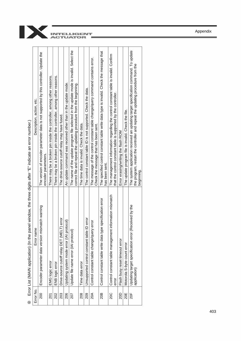
403
Appendix
Erro
r Lis
t (M
AIN
app
licat
ion)
(In
the
pane
l win
dow,
the
thre
e di
gits
afte
r “E”
indi
cate
an
erro
r num
ber.)
Er
ror N
o.
Erro
r nam
e D
escr
iptio
n, a
ctio
n, e
tc.
200
Enc
oder
par
amet
er d
ata
vers
ion
mis
mat
ch w
arni
ng
The
vers
ion
of e
ncod
er p
aram
eter
dat
a is
not
sup
porte
d by
this
con
trolle
r. U
pdat
e th
e en
code
r par
amet
ers.
20
1 E
MG
logi
c er
ror
Ther
e m
ay b
e a
brok
en p
in in
side
the
cont
rolle
r, am
ong
othe
r rea
sons
. 20
2 E
NB
logi
c er
ror
Ther
e m
ay b
e a
brok
en p
in in
side
the
cont
rolle
r, am
ong
othe
r rea
sons
. 20
3 D
rive-
sour
ce c
utof
f rel
ay D
ET
(ME
LT) e
rror
The
driv
e-so
urce
cut
off r
elay
may
hav
e fu
sed.
20
6 U
pdat
ing
syst
em m
ode
erro
r (IA
I pro
toco
l) A
n up
date
com
man
d w
as re
ceiv
ed o
ther
than
in th
e up
date
mod
e.
207
Upd
ate
file
nam
e er
ror (
IAI p
roto
col)
The
nam
e of
the
upda
te p
rogr
am fi
le s
elec
ted
in th
e up
date
mod
e is
inva
lid. S
elec
t the
co
rrec
t file
and
repe
at th
e up
datin
g pr
oced
ure
from
the
begi
nnin
g.
208
Tim
e da
ta e
rror
Th
e tim
e da
ta is
inva
lid. C
heck
the
data
. 20
9 U
nsup
porte
d co
ntro
l con
stan
t tab
le ID
erro
r Th
e co
ntro
l con
stan
t tab
le ID
is n
ot s
uppo
rted.
Che
ck th
e da
ta.
20A
C
ontro
l con
stan
t tab
le c
hang
e/qu
ery
erro
r Th
e m
essa
ge o
f the
con
trol c
onst
ant t
able
cha
nge/
quer
y co
mm
and
cont
ains
err
or.
Che
ck th
e m
essa
ge th
at h
as b
een
sent
. 20
B
Con
trol c
onst
ant t
able
writ
e da
ta ty
pe s
peci
ficat
ion
erro
r Th
e sp
ecifi
ed c
ontro
l con
stan
t tab
le w
rite
data
type
is in
valid
. Che
ck th
e m
essa
ge th
at
has
been
sen
t. 20
C
Con
trol c
onst
ant t
able
man
agem
ent i
nfor
mat
ion
mis
mat
ch
erro
r Th
e m
anag
emen
t inf
orm
atio
n re
gard
ing
the
cont
rol c
onst
ant t
able
is in
valid
. Con
firm
th
at th
e co
ntro
l con
stan
t tab
le is
sup
porte
d by
the
cont
rolle
r. 20
D
Flas
h bu
sy re
set t
imeo
ut e
rror
Erro
r era
sing
/writ
ing
the
flash
RO
M
20E
M
otor
ola
S-b
yte
coun
t erro
r Th
e up
date
pro
gram
file
is in
valid
. Che
ck th
e fil
e.
20F
Upd
atin
g ta
rget
spe
cific
atio
n er
ror (
Rec
eive
d by
the
appl
icat
ion)
Th
e sy
stem
app
licat
ion
rece
ived
an
upda
ting
targ
et s
peci
ficat
ion
com
man
d. T
o up
date
th
e pr
ogra
m, r
esta
rt th
e co
ntro
ller a
nd re
peat
the
upda
ting
proc
edur
e fro
m th
e be
ginn
ing.
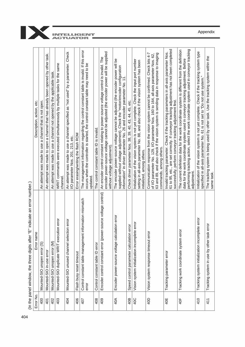
404
Appendix
(In th
e pa
nel w
indo
w, t
he th
ree
digi
ts a
fter “
E” in
dica
te a
n er
ror n
umbe
r.)
Erro
r No.
Er
ror n
ame
Des
crip
tion,
act
ion,
etc
. 40
0 M
ount
ed-S
IO u
nope
n er
ror (
S)
An
atte
mpt
was
mad
e to
use
a c
hann
el th
at is
not
ope
n.
401
Mou
nted
-SIO
in-u
se e
rror
A
n at
tem
pt w
as m
ade
to o
pen
a ch
anne
l tha
t has
alre
ady
been
ope
ned
by o
ther
task
. 40
2 M
ount
ed-S
IO u
nope
n er
ror (
M)
An
atte
mpt
was
mad
e to
use
a c
hann
el n
ot o
pene
d by
the
appl
icab
le ta
sk.
403
Mou
nted
-SIO
dup
licat
e W
RIT
exe
cutio
n er
ror
WR
IT c
omm
ands
wer
e ex
ecut
ed s
imul
tane
ousl
y by
mul
tiple
task
s fo
r the
sam
e ch
anne
l. 40
4 M
ount
ed-S
IO u
nuse
d ch
anne
l sel
ectio
n er
ror
An
atte
mpt
was
mad
e to
use
a c
hann
el s
peci
fied
as “n
ot u
sed”
by
a pa
ram
eter
. Che
ck
I/O p
aram
eter
Nos
. 201
, 213
, etc
. 40
6 Fl
ash
busy
rese
t tim
eout
E
rror e
rasi
ng/w
ritin
g th
e fla
sh R
OM
40
7 C
ontro
l con
stan
t tab
le m
anag
emen
t inf
orm
atio
n m
ism
atch
er
ror
The
man
agem
ent i
nfor
mat
ion
rega
rdin
g th
e co
ntro
l con
stan
t tab
le is
inva
lid. I
f thi
s er
ror
occu
rs w
hen
the
cont
rolle
r is
star
ted,
the
cont
rol c
onst
ant t
able
may
nee
d to
be
upda
ted.
40
8 C
ontro
l con
stan
t tab
le ID
erro
r Th
e co
ntro
l con
stan
t tab
le ID
is in
valid
. 40
9 E
ncod
er c
ontro
l con
stan
t err
or (p
ower
-sou
rce
volta
ge c
ontro
l) A
n en
code
r con
trol c
onst
ant r
elat
ing
to p
ower
-sou
rce
volta
ge c
ontro
l is
inva
lid. T
he
enco
der p
ower
-sou
rce
volta
ge c
anno
t be
adju
sted
(the
enc
oder
pow
er w
ill be
sup
plie
d w
ithou
t vol
tage
adj
ustm
ent).
40
A
Enc
oder
pow
er-s
ourc
e vo
ltage
cal
cula
tion
erro
r Th
e en
code
r pow
er-s
ourc
e vo
ltage
can
not b
e ad
just
ed (t
he e
ncod
er p
ower
will
be
supp
lied
with
out v
olta
ge a
djus
tmen
t). C
heck
the
“mot
or/e
ncod
er c
onfig
urat
ion
info
rmat
ion”
in d
river
par
amet
er N
o. 2
6 an
d en
code
r par
amet
er N
o. 1
1.
40B
S
peed
con
trol p
aram
eter
cal
cula
tion
erro
r C
heck
driv
er p
aram
eter
Nos
. 38,
39,
40,
43,
44,
45,
etc
. 40
C
Vis
ion
syst
em in
itial
izat
ion
inco
mpl
ete
erro
r In
itial
izat
ion
of th
e vi
sion
sys
tem
is n
ot y
et c
ompl
ete.
Che
ck th
e in
put p
ort n
umbe
r se
tting
in a
ll-ax
is p
aram
eter
No.
88,
and
als
o ch
eck
if th
e vi
sion
sys
tem
has
bee
n in
itial
ized
, am
ong
othe
rs.
40D
V
isio
n sy
stem
resp
onse
tim
eout
erro
r C
omm
unic
atio
n re
spon
se fr
om th
e vi
sion
sys
tem
can
not b
e co
nfirm
ed. C
heck
bits
4-7
of
I/O
par
amet
er N
o. 1
29, I
/O p
aram
eter
Nos
. 160
to 1
64, a
ll-ax
is p
aram
eter
Nos
. 62,
63
and
89,
and
als
o ch
eck
if th
e vi
sion
sys
tem
is s
endi
ng d
ata
in re
spon
se to
imag
ing
com
man
ds, a
mon
g ot
hers
. 40
E
Trac
king
par
amet
er e
rror
In
valid
trac
king
par
amet
er. C
heck
if th
e tra
ckin
g pa
ram
eter
s in
all-
axis
par
amet
er N
os.
61 to
95,
etc
., ar
e se
t cor
rect
ly. I
f con
veyo
r tra
ckin
g ad
just
men
t has
not
bee
n co
mpl
eted
su
cces
sful
ly, p
erfo
rm c
onve
yor t
rack
ing
adju
stm
ent f
irst.
40F
Trac
king
wor
k co
ordi
nate
sys
tem
erro
r Th
e cu
rrent
def
initi
on d
ata
for t
he w
ork
coor
dina
te s
yste
m is
diff
eren
t fro
m th
e de
finiti
on
data
for t
he w
ork
coor
dina
te s
yste
m u
sed
in c
onve
yor t
rack
ing
adju
stm
ent.
Bef
ore
perfo
rmin
g tra
ckin
g ac
tion,
sel
ect t
he w
ork
coor
dina
te s
yste
m u
sed
in c
onve
yor t
rack
ing
adju
stm
ent.
410
Trac
king
sys
tem
initi
aliz
atio
n in
com
plet
e er
ror
Initi
aliz
atio
n of
the
visi
on s
yste
m is
not
yet
com
plet
e. C
heck
if th
e tra
ckin
g sy
stem
type
sp
ecifi
ed in
all-
axis
par
amet
er N
o. 6
1 is
not
set
to “D
o no
t use
sys
tem
.” 41
1 Tr
acki
ng s
yste
m in
use
by
othe
r tas
k er
ror
The
track
ing
syst
em is
bei
ng u
sed
by o
ther
task
. Use
the
track
ing
syst
em w
ithin
the
sam
e ta
sk.
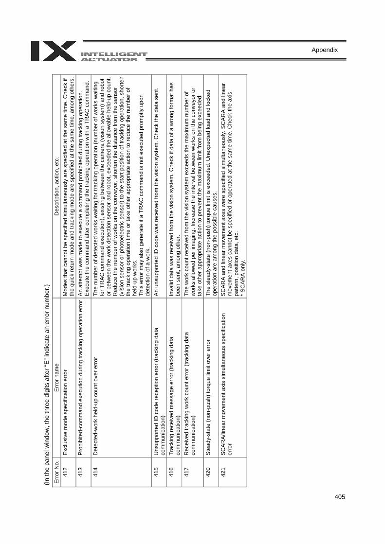
405
Appendix
(In th
e pa
nel w
indo
w, t
he th
ree
digi
ts a
fter “
E” in
dica
te a
n er
ror n
umbe
r.)
Erro
r No.
Er
ror n
ame
Des
crip
tion,
act
ion,
etc
. 41
2 E
xclu
sive
mod
e sp
ecifi
catio
n er
ror
Mod
es th
at c
anno
t be
spec
ified
sim
ulta
neou
sly
are
spec
ified
at t
he s
ame
time.
Che
ck if
th
e qu
ick
retu
rn m
ode
and
track
ing
mod
e ar
e sp
ecifi
ed a
t the
sam
e tim
e, a
mon
g ot
hers
.41
3 P
rohi
bite
d-co
mm
and
exec
utio
n du
ring
track
ing
oper
atio
n er
ror
An
atte
mpt
was
mad
e to
exe
cute
a c
omm
and
proh
ibite
d du
ring
track
ing
oper
atio
n.
Exe
cute
the
com
man
d af
ter c
ompl
etin
g th
e tra
ckin
g op
erat
ion
with
a T
RA
C c
omm
and.
41
4 D
etec
ted-
wor
k he
ld-u
p co
unt o
ver e
rror
Th
e nu
mbe
r of d
etec
ted
wor
ks w
aitin
g fo
r tra
ckin
g op
erat
ion
(num
ber o
f wor
ks w
aitin
g fo
r TR
AC
com
man
d ex
ecut
ion)
, exi
stin
g be
twee
n th
e ca
mer
a (v
isio
n sy
stem
) and
robo
t or
bet
wee
n th
e w
ork
dete
ctio
n se
nsor
and
robo
t, ex
ceed
ed th
e al
low
able
hel
d-up
cou
nt.
Red
uce
the
num
ber o
f wor
ks o
n th
e co
nvey
or, s
horte
n th
e di
stan
ce fr
om th
e se
nsor
(v
isio
n se
nsor
or p
hoto
elec
tric
sens
or) t
o th
e st
art p
ositi
on o
f tra
ckin
g op
erat
ion,
sho
rten
the
track
ing
oper
atio
n tim
e or
take
oth
er a
ppro
pria
te a
ctio
n to
redu
ce th
e nu
mbe
r of
held
-up
wor
ks.
This
err
or m
ay a
lso
gene
rate
if a
TR
AC
com
man
d is
not
exe
cute
d pr
ompt
ly u
pon
dete
ctio
n of
a w
ork.
41
5 U
nsup
porte
d ID
cod
e re
cept
ion
erro
r (tra
ckin
g da
ta
com
mun
icat
ion)
A
n un
supp
orte
d ID
cod
e w
as re
ceiv
ed fr
om th
e vi
sion
sys
tem
. Che
ck th
e da
ta s
ent.
416
Trac
king
rece
ived
mes
sage
err
or (t
rack
ing
data
co
mm
unic
atio
n)
Inva
lid d
ata
was
rece
ived
from
the
visi
on s
yste
m. C
heck
if d
ata
of a
wro
ng fo
rmat
has
be
en s
ent,
amon
g ot
her.
417
Rec
eive
d tra
ckin
g w
ork
coun
t err
or (t
rack
ing
data
co
mm
unic
atio
n)
The
wor
k co
unt r
ecei
ved
from
the
visi
on s
yste
m e
xcee
ds th
e m
axim
um n
umbe
r of
wor
ks a
llow
ed p
er im
agin
g. In
crea
se th
e in
terv
al b
etw
een
wor
ks o
n th
e co
nvey
or o
r ta
ke o
ther
app
ropr
iate
act
ion
to p
reve
nt th
e m
axim
um li
mit
from
bei
ng e
xcee
ded.
42
0 S
tead
y-st
ate
(non
-pus
h) to
rque
lim
it ov
er e
rror
Th
e st
eady
-sta
te (n
on-p
ush)
torq
ue li
mit
is e
xcee
ded.
Une
xpec
ted
load
and
lock
ed
oper
atio
n ar
e am
ong
the
poss
ible
cau
ses.
42
1 S
CA
RA
/line
ar m
ovem
ent a
xis
sim
ulta
neou
s sp
ecifi
catio
n er
ror
SC
AR
A a
nd li
near
mov
emen
t axe
s w
ere
spec
ified
sim
ulta
neou
sly.
SC
AR
A a
nd li
near
m
ovem
ent a
xes
cann
ot b
e sp
ecifi
ed o
r ope
rate
d at
the
sam
e tim
e. C
heck
the
axis
pa
ttern
, pos
ition
dat
a, e
tc.
* SC
ARA
only
.
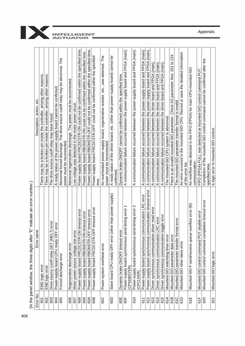
406
Appendix
(In th
e pa
nel w
indo
w, t
he th
ree
digi
ts a
fter “
E” in
dica
te a
n er
ror n
umbe
r.)
Erro
r No.
E
rror n
ame
Des
crip
tion,
act
ion,
etc
. 60
1 E
MG
logi
c er
ror
Ther
e m
ay b
e a
brok
en p
in in
side
the
cont
rolle
r, am
ong
othe
r rea
sons
. 60
2 E
NB
logi
c er
ror
Ther
e m
ay b
e a
brok
en p
in in
side
the
cont
rolle
r, am
ong
othe
r rea
sons
. 60
3 D
rive-
sour
ce c
utof
f rel
ay D
ET
(ME
LT) e
rror
The
driv
e-so
urce
cut
off r
elay
may
hav
e fu
sed.
60
4 P
ower
-sup
ply
boar
d C
PU
read
y O
FF e
rror
A re
ady
stat
us o
f the
pow
er-s
uppl
y bo
ard
cann
ot b
e co
nfirm
ed.
605
Forc
ed d
isch
arge
err
or
Abn
orm
al fo
rced
dis
char
ge. T
he d
rive-
sour
ce c
utof
f rel
ay m
ay b
e ab
norm
al. T
he
pow
er m
ust b
e re
conn
ecte
d.
606
Reg
ener
ativ
e di
scha
rge
erro
r A
bnor
mal
rege
nera
tive
disc
harg
e. T
he p
ower
mus
t be
reco
nnec
ted.
60
7 M
otor
pow
er-s
ourc
e vo
ltage
low
err
or
Low
vol
tage
was
det
ecte
d in
the
mot
or p
ower
circ
uit.
608
Pow
er-s
uppl
y bo
ard
FRC
DC
STR
-ON
tim
eout
err
or
Pow
er-s
uppl
y bo
ard
FRC
DC
STR
-ON
cou
ld n
ot b
e co
nfirm
ed w
ithin
the
spec
ified
tim
e.60
9 P
ower
-sup
ply
boar
d R
BO
NS
TR-O
N ti
meo
ut e
rror
Pow
er-s
uppl
y bo
ard
RB
ON
STR
-ON
cou
ld n
ot b
e co
nfirm
ed w
ithin
the
spec
ified
tim
e.
60A
P
ower
-sup
ply
boar
d R
BO
NS
TR-O
FF ti
meo
ut e
rror
Pow
er-s
uppl
y bo
ard
RB
ON
STR
-OFF
cou
ld n
ot b
e co
nfirm
ed w
ithin
the
spec
ified
tim
e.60
B P
ower
-sup
ply
boar
d FR
CD
CST
R-O
FF ti
meo
ut e
rror
Po
wer
-sup
ply
boar
d FR
CD
CST
R-O
FF c
ould
not
be
conf
irmed
with
in th
e sp
ecifi
ed
time.
60
C
Pow
er-s
yste
m o
verh
eat e
rror
A
n ov
erhe
ated
pow
er-s
uppl
y bo
ard,
rege
nera
tive
resi
stor
, etc
., w
as d
etec
ted.
The
po
wer
mus
t be
reco
nnec
ted.
60
D
Sla
ve b
oard
CPU
read
y O
FF e
rror
(oth
er th
an p
ower
sup
ply)
A
read
y st
atus
of t
he d
river
boa
rd, e
tc. (
othe
r tha
n po
wer
-sup
ply
boar
d) c
anno
t be
conf
irmed
. 60
E
Dyn
amic
bra
ke O
N/O
FF ti
meo
ut e
rror
D
ynam
ic b
rake
ON
/OFF
can
not b
e co
nfirm
ed w
ithin
the
spec
ified
tim
e.
60F
Pow
er-s
uppl
y bo
ard
sync
hron
ous
send
tim
ing
erro
r 1
(CPS
DBS
YER
) A
com
mun
icat
ion
failu
re o
ccur
red
betw
een
the
pow
er-s
uppl
y bo
ard
and
FPG
A (m
ain)
.
610
Pow
er-s
uppl
y bo
ard
sync
hron
ous
send
tim
ing
erro
r 2
(CPC
LKER
) A
com
mun
icat
ion
failu
re o
ccur
red
betw
een
the
pow
er-s
uppl
y bo
ard
and
FPG
A (m
ain)
.
611
Pow
er-s
uppl
y bo
ard
sync
hron
ous
com
mun
icat
ion
LRC
err
or
A c
omm
unic
atio
n fa
ilure
occ
urre
d be
twee
n th
e po
wer
-sup
ply
boar
d an
d FP
GA
(mai
n).
612
Pow
er-s
uppl
y bo
ard
sync
hron
ous
com
mun
icat
ion
timeo
ut e
rror
A
com
mun
icat
ion
failu
re o
ccur
red
betw
een
the
pow
er-s
uppl
y bo
ard
and
FPG
A (m
ain)
.61
3 D
river
syn
chro
nous
com
mun
icat
ion
driv
er re
ad e
rror
A
com
mun
icat
ion
failu
re o
ccur
red
betw
een
the
driv
er b
oard
and
FP
GA
(mai
n).
614
Driv
er s
ynch
rono
us c
omm
unic
atio
n LR
C e
rror
A
com
mun
icat
ion
failu
re o
ccur
red
betw
een
the
driv
er b
oard
and
FP
GA
(mai
n).
615
Driv
er s
ynch
rono
us c
omm
unic
atio
n to
ggle
err
or
A c
omm
unic
atio
n fa
ilure
occ
urre
d be
twee
n th
e dr
iver
boa
rd a
nd F
PG
A (m
ain)
. 61
A
Mou
nted
-SIO
wat
chdo
g tim
er e
rror
Th
e m
ount
ed-S
IO C
PU
sys
tem
is a
bnor
mal
. 61
B
Mou
nted
-SIO
par
amet
er d
ata
erro
r Th
ere
is a
n in
valid
mou
nted
-SIO
par
amet
er. C
heck
I/O
par
amet
er N
os. 2
01 to
224
. 61
C
Mou
nted
-SIO
par
amet
er tr
ansf
er fo
rmat
erro
r Th
e m
ount
ed-S
IO p
aram
eter
tran
sfer
form
at is
inva
lid.
61D
M
ount
ed-S
IO o
ther
sla
ve e
rror
A
n er
ror o
ccur
red
in th
e m
ount
ed-S
IO C
PU
. Rec
ord
or s
ave
the
deta
iled
info
rmat
ion
of th
e er
ror l
ist.
61E
M
ount
ed-S
IO F
-sen
d/re
ceiv
e qu
eue
over
flow
err
or (M
) A
n ov
erflo
w w
as d
etec
ted
in th
e FI
FO (F
PG
A) f
or m
ain
CP
U-m
ount
ed-S
IO
com
mun
icat
ion.
61
F M
ount
ed-S
IO c
ontro
l com
man
d P
UT
disa
ble
erro
r FI
FO (F
PG
A)-F
ULL
was
det
ecte
d at
mou
nted
-SIO
con
trol c
omm
and
PU
T.
620
Mou
nted
-SIO
con
trol c
omm
and
com
plet
ion
timeo
ut e
rror
C
ompl
etio
n of
the
mou
nted
-SIO
con
trol c
omm
and
cann
ot b
e co
nfirm
ed a
fter t
he
spec
ified
tim
e.
621
Mou
nted
-SIO
logi
c er
ror
A lo
gic
erro
r in
mou
nted
-SIO
con
trol.
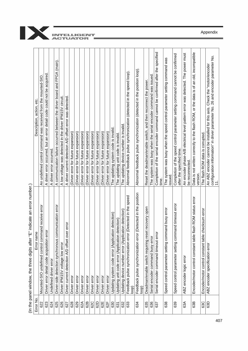
407
Appendix
(In th
e pa
nel w
indo
w, t
he th
ree
digi
ts a
fter “
E” in
dica
te a
n er
ror n
umbe
r.)
Err
or N
o.
Err
or n
ame
Des
crip
tion,
act
ion,
etc
. 62
2 M
ount
ed-S
IO u
ndef
ined
con
trol c
omm
and
rece
ive
erro
r A
n un
defin
ed c
ontro
l com
man
d w
as re
ceiv
ed fr
om th
e m
ount
ed-S
IO.
623
Driv
er e
rror
det
ail c
ode
acqu
isiti
on e
rror
A
driv
er e
rror
occ
urre
d, b
ut a
n er
ror d
etai
l cod
e co
uld
not b
e ac
quire
d.
624
Und
efin
ed d
river
erro
r A
driv
er e
rror o
ccur
red.
62
5 D
river
-sid
e de
tect
ion
sync
hron
ous
com
mun
icat
ion
erro
r A
com
mun
icat
ion
failu
re o
ccur
red
betw
een
the
driv
er b
oard
and
FP
GA
(mai
n).
626
Driv
er IP
M15
V v
olta
ge lo
w e
rror
A
low
vol
tage
was
det
ecte
d in
the
driv
er IP
M15
V c
ircui
t. 62
7 D
river
cur
rent
det
ectio
n A
/D o
ffset
ove
r erro
r A
driv
er c
urre
nt d
etec
tion
A/D
offs
et e
rror
was
det
ecte
d.
628
Driv
er e
rror
(Driv
er e
rror f
or fu
ture
exp
ansi
on)
629
Driv
er e
rror
(Driv
er e
rror f
or fu
ture
exp
ansi
on)
62A
D
river
erro
r (D
river
erro
r for
futu
re e
xpan
sion
) 62
B
Driv
er e
rror
(Driv
er e
rror f
or fu
ture
exp
ansi
on)
62C
D
river
erro
r (D
river
erro
r for
futu
re e
xpan
sion
) 62
D
Driv
er e
rror
(Driv
er e
rror f
or fu
ture
exp
ansi
on)
62E
D
river
erro
r (D
river
erro
r for
futu
re e
xpan
sion
) 62
F D
river
erro
r (D
river
erro
r for
futu
re e
xpan
sion
) 63
0 U
pdat
ing
syst
em c
ode
erro
r (A
pplic
atio
n de
tect
ion)
Th
e up
datin
g sy
stem
cod
e is
inva
lid.
631
Upd
atin
g un
it co
de e
rror
(App
licat
ion
dete
ctio
n)
The
upda
ting
unit
code
is in
valid
. 63
2 U
pdat
ing
devi
ce n
umbe
r err
or (A
pplic
atio
n de
tect
ion)
Th
e up
datin
g de
vice
num
ber i
s in
valid
. 63
3 Fe
edba
ck p
ulse
syn
chro
niza
tion
erro
r (D
etec
ted
in th
e sp
eed
loop
) A
bnor
mal
feed
back
pul
se s
ynch
roni
zatio
n (d
etec
ted
in th
e sp
eed
loop
).
634
Feed
back
pul
se s
ynch
roni
zatio
n er
ror (
Det
ecte
d in
the
posi
tion
loop
) A
bnor
mal
feed
back
pul
se s
ynch
roni
zatio
n (d
etec
ted
in th
e po
sitio
n lo
op).
635
Dea
dman
/ena
ble
switc
h re
quiri
ng re
set r
ecov
ery
open
R
eset
the
dead
man
/ena
ble
switc
h, a
nd th
en re
conn
ect t
he p
ower
. 63
6 S
eria
l enc
oder
com
man
d bu
sy e
rror
Th
e sy
stem
was
bus
y w
hen
the
seria
l enc
oder
com
man
d w
as is
sued
. 63
7 S
eria
l enc
oder
com
man
d tim
eout
err
or
Com
plet
ion
of th
e se
rial e
ncod
er c
omm
and
cann
ot b
e co
nfirm
ed a
fter t
he s
peci
fied
time.
63
8 S
peed
con
trol p
aram
eter
set
ting
com
man
d bu
sy e
rror
Th
e sy
stem
was
bus
y w
hen
the
spee
d co
ntro
l par
amet
er s
ettin
g co
mm
and
was
is
sued
. 63
9 S
peed
con
trol p
aram
eter
set
ting
com
man
d tim
eout
err
or
Com
plet
ion
of th
e sp
eed
cont
rol p
aram
eter
set
ting
com
man
d ca
nnot
be
conf
irmed
af
ter t
he s
peci
fied
time.
63
A
ABZ
enc
oder
logi
c er
ror
An
enco
der p
hase
-A/B
ele
ctric
al le
vel p
atte
rn e
rror w
as d
etec
ted.
The
pow
er m
ust
be re
conn
ecte
d.
63B
E
ncod
er/m
otor
con
trol c
onst
ant t
able
flas
h R
OM
sta
tus
erro
r D
ata
is n
ot w
ritte
n co
rrec
tly to
the
flash
RO
M, o
r the
dat
a is
of a
n ol
d, in
com
patib
le
vers
ion.
63
C
Enc
oder
/mot
or c
ontro
l con
stan
t tab
le c
heck
sum
err
or
The
flash
RO
M d
ata
is c
orru
pted
. 63
D
ABZ
enc
oder
spe
cific
atio
n er
ror
An
AB
Z en
code
r can
not b
e in
stal
led
for t
his
axis
. Che
ck th
e “m
otor
/enc
oder
co
nfig
urat
ion
info
rmat
ion”
in d
river
par
amet
er N
o. 2
6 an
d en
code
r par
amet
er N
o.
11.
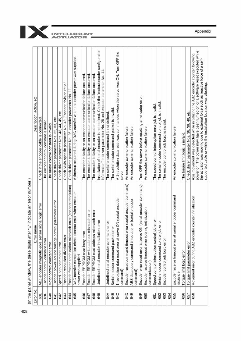
408
Appendix
(In th
e pa
nel w
indo
w, t
he th
ree
digi
ts a
fter “
E” in
dica
te a
n er
ror n
umbe
r.)
Err
or N
o.
Err
or n
ame
Des
crip
tion,
act
ion,
etc
. 63
E
ABZ
enc
oder
mag
netic
-pol
e se
nsor
sig
nal l
ogic
err
or
Che
ck if
the
enco
der c
able
is c
onne
cted
. 63
F E
ncod
er c
ontro
l con
stan
t err
or
The
enco
der c
ontro
l con
stan
t is
inva
lid.
640
Mot
or c
ontro
l con
stan
t erro
r Th
e m
otor
con
trol c
onst
ant i
s in
valid
. 64
1 E
ncod
er p
ower
-sou
rce
volta
ge c
ontro
l par
amet
er e
rror
C
heck
driv
er p
aram
eter
Nos
. 32,
33,
etc
. 64
2 S
peed
loop
par
amet
er e
rror
C
heck
driv
er p
aram
eter
Nos
. 43,
44,
45,
etc
. 64
3 E
ncod
er re
solu
tion
divi
sion
err
or
Che
ck “A
xis-
spec
ific
para
met
er N
o. 4
3: E
ncod
er d
ivis
ion
ratio
.” 64
4 E
ncod
er/m
otor
com
bina
tion
mis
mat
ch e
rror
(enc
oder
reso
lutio
n)
Che
ck d
river
par
amet
er N
o. 2
6, e
ncod
er p
aram
eter
No.
11.
64
5 D
AC
tran
sfer
com
plet
ion
chec
k tim
eout
err
or w
hen
enco
der
pow
er w
as s
uppl
ied
A ti
meo
ut o
ccur
red
durin
g D
AC
tran
sfer
whe
n th
e en
code
r pow
er w
as s
uppl
ied.
646
Enc
oder
EE
PR
OM
read
bus
y er
ror
The
enco
der i
s fa
ulty
or a
n en
code
r com
mun
icat
ion
failu
re o
ccur
red.
64
7 E
ncod
er E
EP
RO
M w
rite
addr
ess
mis
mat
ch e
rror
The
enco
der i
s fa
ulty
or a
n en
code
r com
mun
icat
ion
failu
re o
ccur
red.
64
8 E
ncod
er E
EP
RO
M re
ad a
ddre
ss m
ism
atch
err
or
The
enco
der i
s fa
ulty
or a
n en
code
r com
mun
icat
ion
failu
re o
ccur
red.
64
9 U
ndef
ined
ser
ial e
ncod
er in
stal
latio
n er
ror
Inst
alla
tion
of s
eria
l enc
oder
is n
ot d
efin
ed. C
heck
the
“mot
or/e
ncod
er c
onfig
urat
ion
info
rmat
ion”
in d
river
par
amet
er N
o. 2
6 an
d en
code
r par
amet
er N
o. 1
1.
64A
U
ndef
ined
ser
ial e
ncod
er c
omm
and
erro
r Th
e se
rial e
ncod
er c
omm
and
is n
ot d
efin
ed.
64B
S
eria
l enc
oder
com
man
d pa
cket
erro
r Th
e se
rial e
ncod
er c
omm
and
pack
et is
inva
lid.
64C
1-
revo
lutio
n da
ta re
set e
rror
at s
ervo
ON
(ser
ial e
ncod
er
com
man
d)
A 1
-rev
olut
ion
data
rese
t was
com
man
ded
whe
n th
e se
rvo
was
ON
. Tur
n O
FF th
e se
rvo.
64
D
Enc
oder
rese
t com
man
d tim
eout
err
or (s
eria
l enc
oder
com
man
d)
An
enco
der c
omm
unic
atio
n fa
ilure
. 64
E
AB
S d
ata
quer
y co
mm
and
timeo
ut e
rror (
seria
l enc
oder
co
mm
and)
A
n en
code
r com
mun
icat
ion
failu
re.
64F
Enc
oder
erro
r res
et e
rror a
t ser
vo O
N (s
eria
l enc
oder
com
man
d)
Turn
OFF
the
serv
o be
fore
rese
tting
an
enco
der e
rror
. 65
0 E
ncod
er re
ceiv
e tim
eout
err
or (d
urin
g in
itial
izat
ion
com
mun
icat
ion)
A
n en
code
r com
mun
icat
ion
failu
re.
651
Spe
ed c
ontro
l int
erru
ptio
n co
ntro
l job
err
or
The
spee
d co
ntro
l int
erru
ptio
n er
ror j
ob is
inva
lid.
652
Ser
ial e
ncod
er c
omm
and
cont
rol j
ob e
rror
The
seria
l enc
oder
com
man
d co
ntro
l job
is in
valid
. 65
3 E
ncod
er c
ontro
l job
logi
c er
ror
The
enco
der c
ontro
l job
logi
c is
inva
lid.
654
655
Enc
oder
rece
ive
timeo
ut e
rror
at s
eria
l enc
oder
com
man
d is
suan
ce
An
enco
der c
omm
unic
atio
n fa
ilure
.
656
Torq
ue li
mit
logi
c er
ror
The
torq
ue li
mit
logi
c is
inva
lid.
657
Torq
ue li
mit
para
met
er e
rror
C
heck
driv
er p
aram
eter
Nos
. 38,
39,
40,
etc
. 65
8 M
ovem
ent e
rror
dur
ing
ABZ
enc
oder
cou
nter
initi
aliz
atio
n A
xis
mov
emen
t was
det
ecte
d w
hile
initi
aliz
ing
the
AB
Z en
code
r cou
nter
follo
win
g po
wer
on.
The
pow
er m
ay h
ave
been
turn
ed o
n or
a s
oftw
are
rese
t exe
cute
d w
hile
th
e ac
tuat
or w
as m
ovin
g du
e to
ext
erna
l for
ce s
uch
as re
activ
e fo
rce
of a
sel
f-su
ppor
ted
cabl
e or
whi
le th
e in
stal
latio
n lo
catio
n w
as v
ibra
ting.
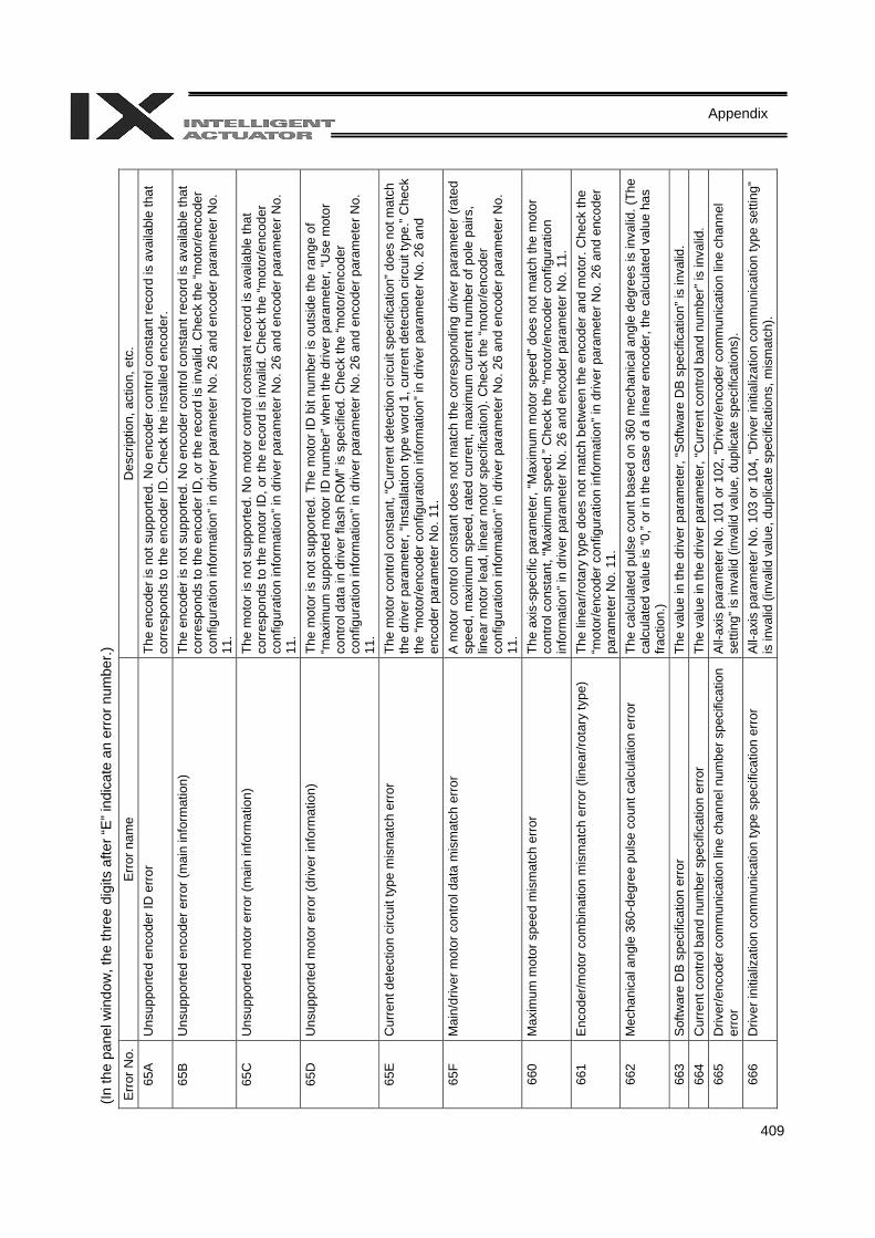
409
Appendix
(In th
e pa
nel w
indo
w, t
he th
ree
digi
ts a
fter “
E” in
dica
te a
n er
ror n
umbe
r.)
Err
or N
o.
Err
or n
ame
Des
crip
tion,
act
ion,
etc
. 65
A
Uns
uppo
rted
enco
der I
D e
rror
The
enco
der i
s no
t sup
porte
d. N
o en
code
r con
trol c
onst
ant r
ecor
d is
ava
ilabl
e th
at
corr
espo
nds
to th
e en
code
r ID
. Che
ck th
e in
stal
led
enco
der.
65B
U
nsup
porte
d en
code
r err
or (m
ain
info
rmat
ion)
Th
e en
code
r is
not s
uppo
rted.
No
enco
der c
ontro
l con
stan
t rec
ord
is a
vaila
ble
that
co
rres
pond
s to
the
enco
der I
D, o
r the
reco
rd is
inva
lid. C
heck
the
“mot
or/e
ncod
er
conf
igur
atio
n in
form
atio
n” in
driv
er p
aram
eter
No.
26
and
enco
der p
aram
eter
No.
11
. 65
C
Uns
uppo
rted
mot
or e
rror (
mai
n in
form
atio
n)
The
mot
or is
not
sup
porte
d. N
o m
otor
con
trol c
onst
ant r
ecor
d is
ava
ilabl
e th
at
corr
espo
nds
to th
e m
otor
ID, o
r the
reco
rd is
inva
lid. C
heck
the
“mot
or/e
ncod
er
conf
igur
atio
n in
form
atio
n” in
driv
er p
aram
eter
No.
26
and
enco
der p
aram
eter
No.
11
. 65
D
Uns
uppo
rted
mot
or e
rror
(driv
er in
form
atio
n)
The
mot
or is
not
sup
porte
d. T
he m
otor
ID b
it nu
mbe
r is
outs
ide
the
rang
e of
“m
axim
um s
uppo
rted
mot
or ID
num
ber”
whe
n th
e dr
iver
par
amet
er, “
Use
mot
or
cont
rol d
ata
in d
river
flas
h R
OM
” is
spec
ified
. Che
ck th
e “m
otor
/enc
oder
co
nfig
urat
ion
info
rmat
ion”
in d
river
par
amet
er N
o. 2
6 an
d en
code
r par
amet
er N
o.
11.
65E
C
urre
nt d
etec
tion
circ
uit t
ype
mis
mat
ch e
rror
The
mot
or c
ontro
l con
stan
t, “C
urre
nt d
etec
tion
circ
uit s
peci
ficat
ion”
doe
s no
t mat
ch
the
driv
er p
aram
eter
, “In
stal
latio
n ty
pe w
ord
1, c
urre
nt d
etec
tion
circ
uit t
ype.
” Che
ck
the
“mot
or/e
ncod
er c
onfig
urat
ion
info
rmat
ion”
in d
river
par
amet
er N
o. 2
6 an
d en
code
r par
amet
er N
o. 1
1.
65F
Mai
n/dr
iver
mot
or c
ontro
l dat
a m
ism
atch
err
or
A m
otor
con
trol c
onst
ant d
oes
not m
atch
the
corr
espo
ndin
g dr
iver
par
amet
er (r
ated
sp
eed,
max
imum
spe
ed, r
ated
cur
rent
, max
imum
cur
rent
num
ber o
f pol
e pa
irs,
linea
r mot
or le
ad, l
inea
r mot
or s
peci
ficat
ion)
. Che
ck th
e “m
otor
/enc
oder
co
nfig
urat
ion
info
rmat
ion”
in d
river
par
amet
er N
o. 2
6 an
d en
code
r par
amet
er N
o.
11.
660
Max
imum
mot
or s
peed
mis
mat
ch e
rror
Th
e ax
is-s
peci
fic p
aram
eter
, “M
axim
um m
otor
spe
ed” d
oes
not m
atch
the
mot
or
cont
rol c
onst
ant,
“Max
imum
spe
ed.”
Che
ck th
e “m
otor
/enc
oder
con
figur
atio
n in
form
atio
n” in
driv
er p
aram
eter
No.
26
and
enco
der p
aram
eter
No.
11.
66
1 E
ncod
er/m
otor
com
bina
tion
mis
mat
ch e
rror (
linea
r/rot
ary
type
) Th
e lin
ear/r
otar
y ty
pe d
oes
not m
atch
bet
wee
n th
e en
code
r and
mot
or. C
heck
the
“mot
or/e
ncod
er c
onfig
urat
ion
info
rmat
ion”
in d
river
par
amet
er N
o. 2
6 an
d en
code
r pa
ram
eter
No.
11.
66
2 M
echa
nica
l ang
le 3
60-d
egre
e pu
lse
coun
t cal
cula
tion
erro
r Th
e ca
lcul
ated
pul
se c
ount
bas
ed o
n 36
0 m
echa
nica
l ang
le d
egre
es is
inva
lid. (
The
calc
ulat
ed v
alue
is “0
,” or
in th
e ca
se o
f a li
near
enc
oder
, the
cal
cula
ted
valu
e ha
s fra
ctio
n.)
663
Sof
twar
e D
B s
peci
ficat
ion
erro
r Th
e va
lue
in th
e dr
iver
par
amet
er, “
Sof
twar
e D
B sp
ecifi
catio
n” is
inva
lid.
664
Cur
rent
con
trol b
and
num
ber s
peci
ficat
ion
erro
r Th
e va
lue
in th
e dr
iver
par
amet
er, “
Cur
rent
con
trol b
and
num
ber”
is in
valid
. 66
5 D
river
/enc
oder
com
mun
icat
ion
line
chan
nel n
umbe
r spe
cific
atio
n er
ror
All-
axis
par
amet
er N
o. 1
01 o
r 102
, “D
river
/enc
oder
com
mun
icat
ion
line
chan
nel
setti
ng” i
s in
valid
(inv
alid
val
ue, d
uplic
ate
spec
ifica
tions
). 66
6 D
river
initi
aliz
atio
n co
mm
unic
atio
n ty
pe s
peci
ficat
ion
erro
r Al
l-axi
s pa
ram
eter
No.
103
or 1
04, “
Driv
er in
itial
izat
ion
com
mun
icat
ion
type
set
ting”
is
inva
lid (i
nval
id v
alue
, dup
licat
e sp
ecifi
catio
ns, m
ism
atch
).
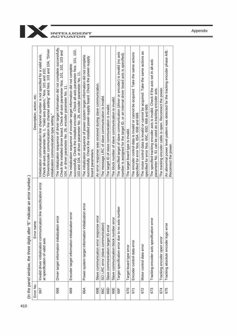
410
Appendix
(In th
e pa
nel w
indo
w, t
he th
ree
digi
ts a
fter “
E” in
dica
te a
n er
ror n
umbe
r.)
Err
or N
o.
Err
or n
ame
Des
crip
tion,
act
ion,
etc
. 66
7 In
valid
driv
er in
itial
izat
ion
com
mun
icat
ion
line
spec
ifica
tion
erro
r at
spe
cific
atio
n of
val
id a
xis
Initi
aliz
atio
n co
mm
unic
atio
n lin
e ch
anne
l num
ber i
s no
t spe
cifie
d fo
r a v
alid
axi
s.
Che
ck a
ll-ax
is p
aram
eter
No.
1, “
Val
id a
xis
patte
rn,”
Nos
. 101
and
102
, “D
river
/enc
oder
com
mun
icat
ion
line
chan
nel s
ettin
g” a
nd N
os. 1
03 a
nd 1
04, “
Driv
er
initi
aliz
atio
n co
mm
unic
atio
n ty
pe s
ettin
g.”
668
Driv
er ta
rget
info
rmat
ion
initi
aliz
atio
n er
ror
The
initi
aliz
atio
n se
quen
ce o
f driv
er ta
rget
info
rmat
ion
did
not c
ompl
ete
succ
essf
ully
. C
heck
the
inst
alle
d dr
iver
boa
rd. C
heck
all-
axis
par
amet
er N
os. 1
01, 1
02, 1
03 a
nd
104,
or d
river
par
amet
er N
o. 2
6, e
ncod
er p
aram
eter
No.
11.
66
9 E
ncod
er ta
rget
info
rmat
ion
initi
aliz
atio
n er
ror
The
initi
aliz
atio
n se
quen
ce o
f enc
oder
targ
et in
form
atio
n di
d no
t com
plet
e su
cces
sful
ly. C
heck
the
inst
alle
d en
code
r. C
heck
all-
axis
par
amet
er N
os. 1
01, 1
02,
103
and
104,
or d
river
par
amet
er N
o. 2
6, e
ncod
er p
aram
eter
No.
11.
66
A
Pow
er-s
yste
m ta
rget
info
rmat
ion
initi
aliz
atio
n er
ror
The
initi
aliz
atio
n se
quen
ce o
f pow
er-s
yste
m ta
rget
info
rmat
ion
did
not c
ompl
ete
succ
essf
ully
. Che
ck th
e in
stal
led
pow
er-s
uppl
y bo
ard.
Che
ck th
e po
wer
-sup
ply
boar
d pa
ram
eter
s.
66B
S
lave
com
mun
icat
ion
erro
r res
pons
e er
ror
An
erro
r res
pons
e w
as re
ceiv
ed d
urin
g sl
ave
com
mun
icat
ion.
66
C
SC
I LR
C e
rror (
slav
e co
mm
unic
atio
n)
The
mes
sage
LR
C o
f sla
ve c
omm
unic
atio
n is
inva
lid.
66D
S
lave
com
mun
icat
ion
targ
et ID
erro
r Th
e ta
rget
ID o
f sla
ve c
omm
unic
atio
n is
inva
lid.
66E
S
lave
com
mun
icat
ion
bloc
k nu
mbe
r erro
r Th
e bl
ock
num
ber o
f sla
ve c
omm
unic
atio
n is
inva
lid.
66F
Targ
et s
peci
ficat
ion
erro
r due
to n
o ax
is n
umbe
r Th
e sp
ecifi
ed ta
rget
of s
lave
com
mun
icat
ion
(driv
er o
r enc
oder
) is
inva
lid (n
o ax
is
num
ber i
s as
sign
ed fo
r the
targ
et ID
, or a
n in
tern
al d
river
boa
rd a
xis
is s
peci
fied)
. 67
0 Ta
rget
boa
rd ty
pe e
rror
Th
e ta
rget
boa
rd ty
pe is
inva
lid.
671
Enc
oder
con
trol d
ata
erro
r Th
e en
code
r con
trol d
ata
is in
valid
or c
anno
t be
acqu
ired.
Tak
e th
e sa
me
actio
ns
spec
ified
for e
rror
Nos
. 65A
, 65B
and
669
. 67
2 M
otor
con
trol d
ata
erro
r Th
e m
otor
con
trol d
ata
is in
valid
or c
anno
t be
acqu
ired.
Tak
e th
e sa
me
actio
ns a
s sp
ecifi
ed fo
r err
or N
os. 6
5C, 6
5D, 6
68 a
nd 6
69.
673
Trac
king
-enc
oder
axi
s sp
ecifi
catio
n er
ror
The
spec
ified
trac
king
enc
oder
axi
s is
inva
lid. C
heck
if th
e ax
is s
et in
all-
axis
pa
ram
eter
No.
61
can
be u
sed
as a
trac
king
enc
oder
axi
s.
674
Trac
king
enc
oder
ope
n er
ror
The
track
ing
enco
der c
able
is o
pen.
Rec
onne
ct th
e po
wer
. 67
5 Tr
acki
ng a
bsol
ute
enco
der l
ogic
erro
r A
n ab
norm
al p
ower
leve
l pat
tern
was
det
ecte
d fo
r the
trac
king
enc
oder
pha
se A
/B.
Rec
onne
ct th
e po
wer
.
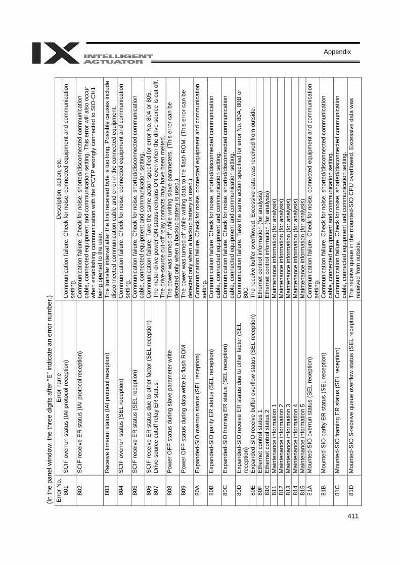
411
Appendix
(In th
e pa
nel w
indo
w, t
he th
ree
digi
ts a
fter “
E” in
dica
te a
n er
ror n
umbe
r.)
Err
or N
o.
Err
or n
ame
Des
crip
tion,
act
ion,
etc
. 80
1 S
CIF
ove
rrun
sta
tus
(IAI p
roto
col r
ecep
tion)
C
omm
unic
atio
n fa
ilure
. Che
ck fo
r noi
se, c
onne
cted
equ
ipm
ent a
nd c
omm
unic
atio
n se
tting
. 80
2 S
CIF
rece
ive
ER
sta
tus
(IAI p
roto
col r
ecep
tion)
C
omm
unic
atio
n fa
ilure
. Che
ck fo
r noi
se, s
horte
d/di
scon
nect
ed c
omm
unic
atio
n ca
ble,
con
nect
ed e
quip
men
t and
com
mun
icat
ion
setti
ng. T
his
erro
r will
also
occ
ur
whe
n es
tabl
ishi
ng c
omm
unic
atio
n w
ith th
e P
C/T
P w
rong
ly c
onne
cted
to S
IO-C
H1
bein
g op
ened
to th
e us
er.
803
Rec
eive
tim
eout
sta
tus
(IAI p
roto
col r
ecep
tion)
Th
e tra
nsfe
r int
erva
l afte
r the
firs
t rec
eive
d by
te is
too
long
. Pos
sibl
e ca
uses
incl
ude
disc
onne
cted
com
mun
icat
ion
cabl
e an
d er
ror i
n th
e co
nnec
ted
equi
pmen
t. 80
4 S
CIF
ove
rrun
stat
us (S
EL
rece
ptio
n)
Com
mun
icat
ion
failu
re. C
heck
for n
oise
, con
nect
ed e
quip
men
t and
com
mun
icat
ion
setti
ng.
805
SC
IF re
ceiv
e E
R s
tatu
s (S
EL
rece
ptio
n)
Com
mun
icat
ion
failu
re. C
heck
for n
oise
, sho
rted/
disc
onne
cted
com
mun
icat
ion
cabl
e, c
onne
cted
equ
ipm
ent a
nd c
omm
unic
atio
n se
tting
. 80
6 S
CIF
rece
ive
ER
sta
tus
due
to o
ther
fact
or (S
EL
rece
ptio
n)
Com
mun
icat
ion
failu
re. T
ake
the
sam
e ac
tion
spec
ified
for e
rror
No.
804
or 8
05.
807
Driv
e-so
urce
cut
off r
elay
ER
sta
tus
The
mot
or-d
rive
pow
er O
N s
tatu
s re
mai
ns O
N e
ven
whe
n th
e dr
ive
sour
ce is
cut
off.
Th
e dr
ive-
sour
ce c
ut-o
ff re
lay
cont
acts
may
hav
e be
en m
elte
d.
808
Pow
er O
FF s
tatu
s du
ring
slav
e pa
ram
eter
writ
e Th
e po
wer
was
turn
ed o
ff w
hile
writ
ing
slav
e pa
ram
eter
s. (T
his
erro
r can
be
dete
cted
onl
y w
hen
a ba
ckup
bat
tery
is u
sed.
) 80
9 P
ower
OFF
sta
tus
durin
g da
ta w
rite
to fl
ash
RO
M
The
pow
er w
as tu
rned
off
whi
le w
ritin
g da
ta to
the
flash
RO
M. (
This
erro
r can
be
dete
cted
onl
y w
hen
a ba
ckup
bat
tery
is u
sed.
) 80
A
Exp
ande
d-S
IO o
verr
un s
tatu
s (S
EL
rece
ptio
n)
Com
mun
icat
ion
failu
re. C
heck
for n
oise
, con
nect
ed e
quip
men
t and
com
mun
icat
ion
setti
ng.
80B
E
xpan
ded-
SIO
par
ity E
R s
tatu
s (S
EL
rece
ptio
n)
Com
mun
icat
ion
failu
re. C
heck
for n
oise
, sho
rted/
disc
onne
cted
com
mun
icat
ion
cabl
e, c
onne
cted
equ
ipm
ent a
nd c
omm
unic
atio
n se
tting
. 80
C
Exp
ande
d-S
IO fr
amin
g E
R s
tatu
s (S
EL
rece
ptio
n)
Com
mun
icat
ion
failu
re. C
heck
for n
oise
, sho
rted/
disc
onne
cted
com
mun
icat
ion
cabl
e, c
onne
cted
equ
ipm
ent a
nd c
omm
unic
atio
n se
tting
. 80
D
Exp
ande
d-S
IO re
ceiv
e E
R s
tatu
s du
e to
oth
er fa
ctor
(SE
L re
cept
ion)
C
omm
unic
atio
n fa
ilure
. Tak
e th
e sa
me
actio
n sp
ecifi
ed fo
r err
or N
o. 8
0A, 8
0B o
r 80
C.
80E
E
xpan
ded-
SIO
rece
ive
buffe
r ove
rflow
sta
tus
(SE
L re
cept
ion)
Th
e re
ceiv
e bu
ffer o
verfl
owed
. Exc
essi
ve d
ata
was
rece
ived
from
out
side
. 80
F E
ther
net c
ontro
l sta
tus
1 E
ther
net c
ontro
l inf
orm
atio
n (fo
r ana
lysi
s)
810
Eth
erne
t con
trol s
tatu
s 2
Eth
erne
t con
trol i
nfor
mat
ion
(for a
naly
sis)
81
1 M
aint
enan
ce in
form
atio
n 1
Mai
nten
ance
info
rmat
ion
(for a
naly
sis)
81
2 M
aint
enan
ce in
form
atio
n 2
Mai
nten
ance
info
rmat
ion
(for a
naly
sis)
81
3 M
aint
enan
ce in
form
atio
n 3
Mai
nten
ance
info
rmat
ion
(for a
naly
sis)
81
4 M
aint
enan
ce in
form
atio
n 4
Mai
nten
ance
info
rmat
ion
(for a
naly
sis)
81
5 M
aint
enan
ce in
form
atio
n 5
Mai
nten
ance
info
rmat
ion
(for a
naly
sis)
81
A
Mou
nted
-SIO
ove
rrun
sta
tus
(SE
L re
cept
ion)
C
omm
unic
atio
n fa
ilure
. Che
ck fo
r noi
se, c
onne
cted
equ
ipm
ent a
nd c
omm
unic
atio
n se
tting
. 81
B
Mou
nted
-SIO
par
ity E
R s
tatu
s (S
EL
rece
ptio
n)
Com
mun
icat
ion
failu
re. C
heck
for n
oise
, sho
rted/
disc
onne
cted
com
mun
icat
ion
cabl
e, c
onne
cted
equ
ipm
ent a
nd c
omm
unic
atio
n se
tting
. 81
C
Mou
nted
-SIO
fram
ing
ER
sta
tus
(SE
L re
cept
ion)
C
omm
unic
atio
n fa
ilure
. Che
ck fo
r noi
se, s
horte
d/di
scon
nect
ed c
omm
unic
atio
n ca
ble,
con
nect
ed e
quip
men
t and
com
mun
icat
ion
setti
ng.
81D
M
ount
ed-S
IO S
-rec
eive
que
ue o
verfl
ow s
tatu
s (S
EL
rece
ptio
n)
The
rece
ive
queu
e in
the
mou
nted
-SIO
CP
U o
verfl
owed
. Exc
essi
ve d
ata
was
re
ceiv
ed fr
om o
utsi
de.
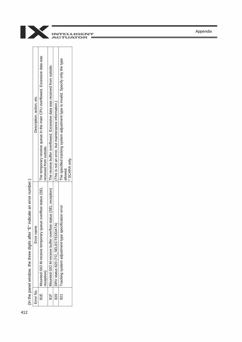
412
Appendix
(In th
e pa
nel w
indo
w, t
he th
ree
digi
ts a
fter “
E” in
dica
te a
n er
ror n
umbe
r.)
Err
or N
o.
Err
or n
ame
Des
crip
tion,
act
ion,
etc
. 81
E
Mou
nted
-SIO
M-r
ecei
ve te
mpo
rary
que
ue o
verfl
ow s
tatu
s (S
EL
rece
ptio
n)
The
tem
pora
ry re
ceiv
e qu
eue
in th
e m
ain
CP
U o
verfl
owed
. Exc
essi
ve d
ata
was
re
ceiv
ed fr
om o
utsi
de.
81F
Mou
nted
-SIO
M-r
ecei
ve b
uffe
r ove
rflow
sta
tus
(SE
L re
cept
ion)
Th
e re
ceiv
e bu
ffer o
verfl
owed
. Exc
essi
ve d
ata
was
rece
ived
from
out
side
. 82
0 D
RV
sta
tus
820
(TO
_SE
LEC
TED
DAT
A)
(Thi
s is
not
an
erro
r, bu
t mai
nten
ance
info
rmat
ion.
) 82
1 Tr
acki
ng s
yste
m a
djus
tmen
t-typ
e sp
ecifi
catio
n er
ror
The
spec
ified
trac
king
sys
tem
adj
ustm
ent t
ype
is in
valid
. Spe
cify
onl
y th
e ty
pe
allo
wed
. *
SC
AR
A o
nly.
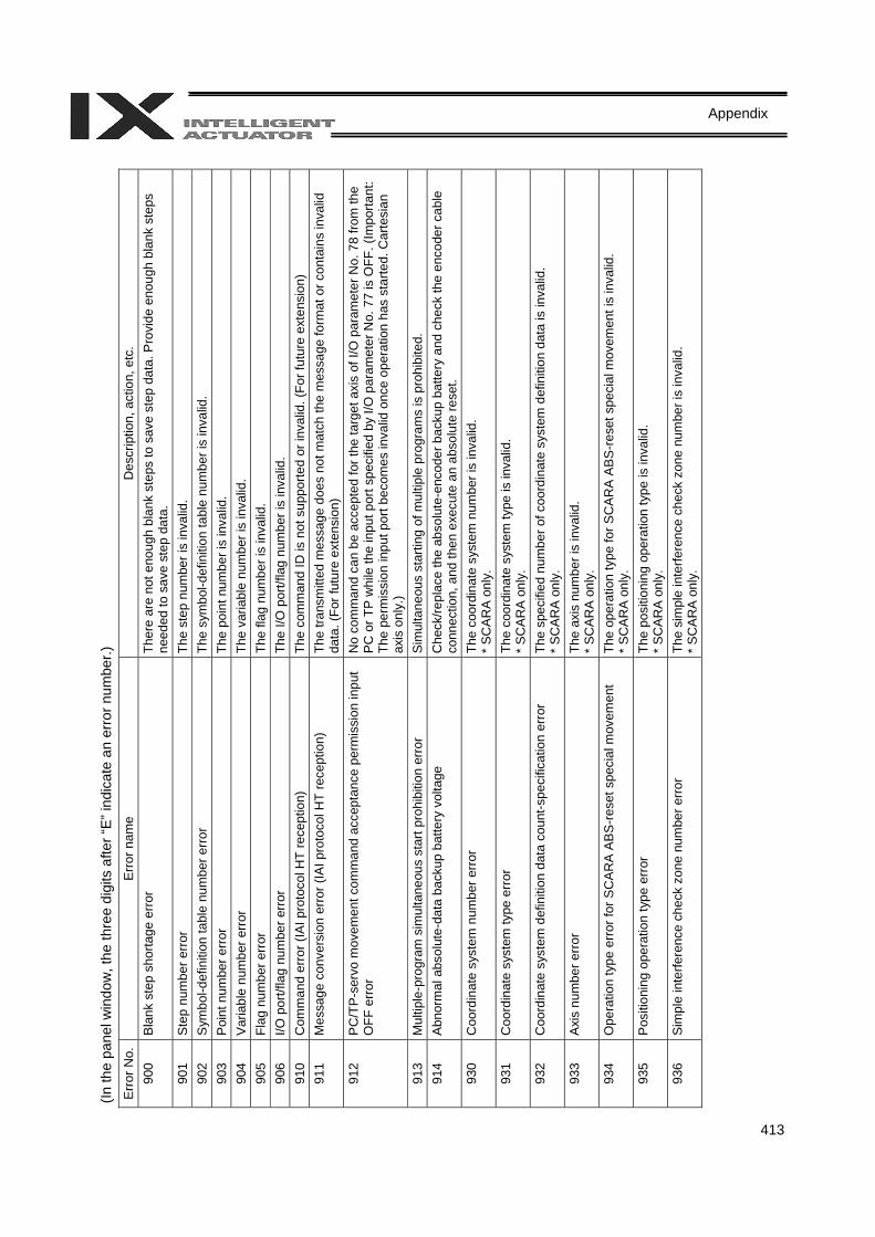
413
Appendix
(In th
e pa
nel w
indo
w, t
he th
ree
digi
ts a
fter “
E” in
dica
te a
n er
ror n
umbe
r.)
Err
or N
o.
Err
or n
ame
Des
crip
tion,
act
ion,
etc
. 90
0 B
lank
ste
p sh
orta
ge e
rror
Th
ere
are
not e
noug
h bl
ank
step
s to
sav
e st
ep d
ata.
Pro
vide
eno
ugh
blan
k st
eps
need
ed to
sav
e st
ep d
ata.
90
1 S
tep
num
ber e
rror
Th
e st
ep n
umbe
r is
inva
lid.
902
Sym
bol-d
efin
ition
tabl
e nu
mbe
r err
or
The
sym
bol-d
efin
ition
tabl
e nu
mbe
r is
inva
lid.
903
Poi
nt n
umbe
r err
or
The
poin
t num
ber i
s in
valid
. 90
4 V
aria
ble
num
ber e
rror
Th
e va
riabl
e nu
mbe
r is
inva
lid.
905
Flag
num
ber e
rror
Th
e fla
g nu
mbe
r is
inva
lid.
906
I/O p
ort/f
lag
num
ber e
rror
The
I/O p
ort/f
lag
num
ber i
s in
valid
. 91
0 C
omm
and
erro
r (IA
I pro
toco
l HT
rece
ptio
n)
The
com
man
d ID
is n
ot s
uppo
rted
or in
valid
. (Fo
r fut
ure
exte
nsio
n)
911
Mes
sage
con
vers
ion
erro
r (IA
I pro
toco
l HT
rece
ptio
n)
The
trans
mitt
ed m
essa
ge d
oes
not m
atch
the
mes
sage
form
at o
r con
tain
s in
valid
da
ta. (
For f
utur
e ex
tens
ion)
91
2 P
C/T
P-s
ervo
mov
emen
t com
man
d ac
cept
ance
per
mis
sion
inpu
t O
FF e
rror
No
com
man
d ca
n be
acc
epte
d fo
r the
targ
et a
xis
of I/
O p
aram
eter
No.
78
from
the
PC
or T
P w
hile
the
inpu
t por
t spe
cifie
d by
I/O
par
amet
er N
o. 7
7 is
OFF
. (Im
porta
nt:
The
perm
issi
on in
put p
ort b
ecom
es in
valid
onc
e op
erat
ion
has
star
ted.
Car
tesi
an
axis
onl
y.)
913
Mul
tiple
-pro
gram
sim
ulta
neou
s st
art p
rohi
bitio
n er
ror
Sim
ulta
neou
s st
artin
g of
mul
tiple
pro
gram
s is
pro
hibi
ted.
91
4 A
bnor
mal
abs
olut
e-da
ta b
acku
p ba
ttery
vol
tage
C
heck
/repl
ace
the
abso
lute
-enc
oder
bac
kup
batte
ry a
nd c
heck
the
enco
der c
able
co
nnec
tion,
and
then
exe
cute
an
abso
lute
rese
t. 93
0 C
oord
inat
e sy
stem
num
ber e
rror
Th
e co
ordi
nate
sys
tem
num
ber i
s in
valid
. *
SC
AR
A o
nly.
93
1 C
oord
inat
e sy
stem
type
err
or
The
coor
dina
te s
yste
m ty
pe is
inva
lid.
* S
CA
RA
onl
y.
932
Coo
rdin
ate
syst
em d
efin
ition
dat
a co
unt-s
peci
ficat
ion
erro
r Th
e sp
ecifi
ed n
umbe
r of c
oord
inat
e sy
stem
def
initi
on d
ata
is in
valid
. *
SC
AR
A o
nly.
93
3 A
xis
num
ber e
rror
Th
e ax
is n
umbe
r is
inva
lid.
* S
CA
RA
onl
y.
934
Ope
ratio
n ty
pe e
rror f
or S
CA
RA
AB
S-re
set s
peci
al m
ovem
ent
The
oper
atio
n ty
pe fo
r SC
AR
A A
BS
-res
et s
peci
al m
ovem
ent i
s in
valid
. *
SC
AR
A o
nly.
93
5 P
ositi
onin
g op
erat
ion
type
err
or
The
posi
tioni
ng o
pera
tion
type
is in
valid
. *
SC
AR
A o
nly.
93
6 S
impl
e in
terfe
renc
e ch
eck
zone
num
ber e
rror
Th
e si
mpl
e in
terfe
renc
e ch
eck
zone
num
ber i
s in
valid
. *
SC
AR
A o
nly.
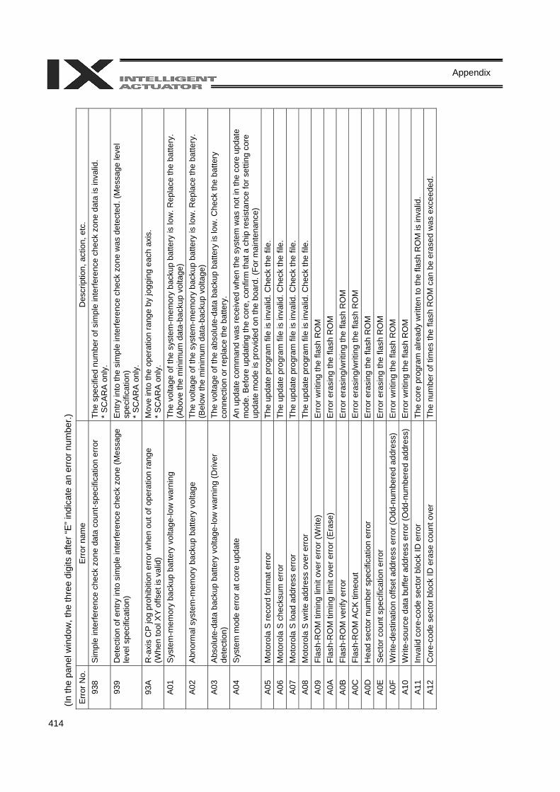
414
Appendix
(In th
e pa
nel w
indo
w, t
he th
ree
digi
ts a
fter “
E” in
dica
te a
n er
ror n
umbe
r.)
Err
or N
o.
Err
or n
ame
Des
crip
tion,
act
ion,
etc
. 93
8 S
impl
e in
terfe
renc
e ch
eck
zone
dat
a co
unt-s
peci
ficat
ion
erro
r Th
e sp
ecifi
ed n
umbe
r of s
impl
e in
terfe
renc
e ch
eck
zone
dat
a is
inva
lid.
* S
CA
RA
onl
y.
939
Det
ectio
n of
ent
ry in
to s
impl
e in
terfe
renc
e ch
eck
zone
(Mes
sage
le
vel s
peci
ficat
ion)
E
ntry
into
the
sim
ple
inte
rfere
nce
chec
k zo
ne w
as d
etec
ted.
(Mes
sage
leve
l sp
ecifi
catio
n)
* S
CA
RA
onl
y.
93A
R
-axi
s C
P jo
g pr
ohib
ition
erro
r whe
n ou
t of o
pera
tion
rang
e (W
hen
tool
XY
offs
et is
val
id)
Mov
e in
to th
e op
erat
ion
rang
e by
jogg
ing
each
axi
s.
* S
CA
RA
onl
y.
A01
S
yste
m-m
emor
y ba
ckup
bat
tery
vol
tage
-low
war
ning
Th
e vo
ltage
of t
he s
yste
m-m
emor
y ba
ckup
bat
tery
is lo
w. R
epla
ce th
e ba
ttery
. (A
bove
the
min
imum
dat
a-ba
ckup
vol
tage
) A
02
Abn
orm
al s
yste
m-m
emor
y ba
ckup
bat
tery
vol
tage
Th
e vo
ltage
of t
he s
yste
m-m
emor
y ba
ckup
bat
tery
is lo
w. R
epla
ce th
e ba
ttery
. (B
elow
the
min
imum
dat
a-ba
ckup
vol
tage
) A
03
Abs
olut
e-da
ta b
acku
p ba
ttery
vol
tage
-low
war
ning
(Driv
er
dete
ctio
n)
The
volta
ge o
f the
abs
olut
e-da
ta b
acku
p ba
ttery
is lo
w. C
heck
the
batte
ry
conn
ectio
n or
repl
ace
the
batte
ry.
A04
S
yste
m m
ode
erro
r at c
ore
upda
te
An
upda
te c
omm
and
was
rece
ived
whe
n th
e sy
stem
was
not
in th
e co
re u
pdat
e m
ode.
Bef
ore
upda
ting
the
core
, con
firm
that
a c
hip
resi
stan
ce fo
r set
ting
core
up
date
mod
e is
pro
vide
d on
the
boar
d. (F
or m
aint
enan
ce)
A05
M
otor
ola
S re
cord
form
at e
rror
Th
e up
date
pro
gram
file
is in
valid
. Che
ck th
e fil
e.
A06
M
otor
ola
S c
heck
sum
err
or
The
upda
te p
rogr
am fi
le is
inva
lid. C
heck
the
file.
A
07
Mot
orol
a S
load
add
ress
err
or
The
upda
te p
rogr
am fi
le is
inva
lid. C
heck
the
file.
A
08
Mot
orol
a S
writ
e ad
dres
s ov
er e
rror
The
upda
te p
rogr
am fi
le is
inva
lid. C
heck
the
file.
A
09
Flas
h-R
OM
tim
ing
limit
over
err
or (W
rite)
E
rror w
ritin
g th
e fla
sh R
OM
A
0A
Flas
h-R
OM
tim
ing
limit
over
err
or (E
rase
) E
rror e
rasi
ng th
e fla
sh R
OM
A
0B
Flas
h-R
OM
ver
ify e
rror
Erro
r era
sing
/writ
ing
the
flash
RO
M
A0C
Fl
ash-
RO
M A
CK
tim
eout
E
rror
era
sing
/writ
ing
the
flash
RO
M
A0D
H
ead
sect
or n
umbe
r spe
cific
atio
n er
ror
Err
or e
rasi
ng th
e fla
sh R
OM
A
0E
Sec
tor c
ount
spe
cific
atio
n er
ror
Err
or e
rasi
ng th
e fla
sh R
OM
A
0F
Writ
e-de
stin
atio
n of
fset
add
ress
err
or (O
dd-n
umbe
red
addr
ess)
E
rror
writ
ing
the
flash
RO
M
A10
W
rite-
sour
ce d
ata
buffe
r add
ress
err
or (O
dd-n
umbe
red
addr
ess)
E
rror
writ
ing
the
flash
RO
M
A11
In
valid
cor
e-co
de s
ecto
r blo
ck ID
err
or
The
core
pro
gram
alre
ady
writ
ten
to th
e fla
sh R
OM
is in
valid
. A
12
Cor
e-co
de s
ecto
r blo
ck ID
era
se c
ount
ove
r Th
e nu
mbe
r of t
imes
the
flash
RO
M c
an b
e er
ased
was
exc
eede
d.
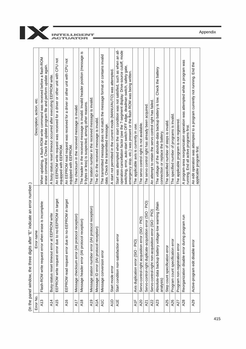
415
Appendix
(In th
e pa
nel w
indo
w, t
he th
ree
digi
ts a
fter “
E” in
dica
te a
n er
ror n
umbe
r.)
Err
or N
o.
Err
or n
ame
Des
crip
tion,
act
ion,
etc
. A
13
Flas
h-R
OM
writ
e re
ques
t err
or w
hen
eras
e is
inco
mpl
ete
Whe
n up
datin
g, a
flas
h-R
OM
writ
e co
mm
and
was
rece
ived
bef
ore
a fla
sh-R
OM
er
ase
com
man
d. C
heck
the
upda
te p
rogr
am fi
le a
nd p
erfo
rm u
pdat
e ag
ain.
A
14
Bus
y-st
atus
rese
t tim
eout
err
or a
t EE
PR
OM
writ
e A
bus
y-st
atus
rese
t tim
eout
occ
urre
d af
ter e
xecu
ting
EEP
RO
M w
rite.
A
15
EE
PR
OM
writ
e re
ques
t erro
r due
to n
o-E
EP
RO
M in
targ
et
An
EE
PR
OM
writ
e re
ques
t was
rece
ived
for a
driv
er o
r oth
er u
nit w
ith C
PU
not
eq
uipp
ed w
ith E
EP
RO
M.
A16
E
EP
RO
M re
ad re
ques
t erro
r due
to n
o-E
EP
RO
M in
targ
et
An
EE
PR
OM
read
requ
est w
as re
ceiv
ed fo
r a d
river
or o
ther
uni
t with
CP
U n
ot
equi
pped
with
EE
PR
OM
. A
17
Mes
sage
che
cksu
m e
rror
(IA
I pro
toco
l rec
eptio
n)
The
chec
ksum
in th
e re
ceiv
ed m
essa
ge is
inva
lid.
A18
M
essa
ge h
eade
r err
or (I
AI p
roto
col r
ecep
tion)
Th
e he
ader
in th
e re
ceiv
ed m
essa
ge is
inva
lid. I
nval
id h
eade
r pos
ition
(mes
sage
is
9 by
tes
or le
ss) i
s su
spec
ted,
am
ong
othe
r rea
sons
. A
19
Mes
sage
sta
tion
num
ber e
rror
(IA
I pro
toco
l rec
eptio
n)
The
stat
ion
num
ber i
n th
e re
ceiv
ed m
essa
ge is
inva
lid.
A1A
M
essa
ge ID
err
or (I
AI p
roto
col r
ecep
tion)
Th
e ID
in th
e re
ceiv
ed m
essa
ge is
inva
lid.
A1C
M
essa
ge c
onve
rsio
n er
ror
The
trans
mitt
ed m
essa
ge d
oes
not m
atch
the
mes
sage
form
at o
r con
tain
s in
valid
da
ta. C
heck
the
trans
mitt
ed m
essa
ge.
A1D
S
tart
mod
e er
ror
A st
art n
ot p
erm
itted
in th
e cu
rrent
mod
e (M
ANU
/AU
TO) w
as a
ttem
pted
. A
1E
Sta
rt co
nditi
on n
on-s
atis
fact
ion
erro
r S
tart
was
atte
mpt
ed w
hen
the
star
t con
ditio
n w
as n
ot s
atis
fied,
suc
h as
whe
n an
all-
oper
atio
n-ca
ncel
latio
n fa
ctor
(see
the
7-se
gmen
t dis
play
: Driv
e-so
urce
cut
off,
mod
e sw
itchi
ng, e
rror
, aut
o-st
art s
witc
h O
FF e
dge,
dea
dman
sw
itch,
saf
ety
gate
, em
erge
ncy
stop
, etc
.) w
as p
rese
nt o
r the
flas
h R
OM
was
bei
ng w
ritte
n.
A1F
A
xis
dupl
icat
ion
erro
r (S
IO
PIO
) Th
e ap
plic
able
axi
s is
cur
rent
ly in
use
. A
20
Ser
vo-c
ontro
l-rig
ht a
cqui
sitio
n er
ror (
SIO
PI
O)
The
serv
o co
ntro
l rig
ht is
not
ava
ilabl
e.
A21
S
ervo
-con
trol-r
ight
dup
licat
e-ac
quis
ition
err
or (S
IO
PIO
) Th
e se
rvo
cont
rol r
ight
has
alre
ady
been
acq
uire
d.
A22
S
ervo
-con
trol-r
ight
non
-acq
uisi
tion
erro
r (S
IO
PIO
) An
atte
mpt
to re
tain
the
serv
o co
ntro
l rig
ht h
as fa
iled.
A
23
Abs
olut
e-da
ta b
acku
p ba
ttery
vol
tage
-low
war
ning
(Mai
n an
alys
is)
The
volta
ge o
f the
abs
olut
e-da
ta b
acku
p ba
ttery
is lo
w. C
heck
the
batte
ry
conn
ectio
n or
repl
ace
the
batte
ry.
A25
S
tep
coun
t spe
cific
atio
n er
ror
The
spec
ified
num
ber o
f ste
ps is
inva
lid.
A26
P
rogr
am c
ount
spe
cific
atio
n er
ror
The
spec
ified
num
ber o
f pro
gram
s is
inva
lid.
A27
P
rogr
am n
on-r
egis
tratio
n er
ror
The
appl
icab
le p
rogr
am is
not
regi
ster
ed.
A28
R
eorg
aniz
atio
n di
sabl
e er
ror d
urin
g pr
ogra
m ru
n A
pro
gram
-are
a re
orga
niza
tion
oper
atio
n w
as a
ttem
pted
whi
le a
pro
gram
was
ru
nnin
g. E
nd a
ll ac
tive
prog
ram
s fir
st.
A29
A
ctiv
e-pr
ogra
m e
dit d
isab
le e
rror
A
n ed
it op
erat
ion
was
atte
mpt
ed to
a p
rogr
am c
urre
ntly
not
runn
ing.
End
the
appl
icab
le p
rogr
am fi
rst.
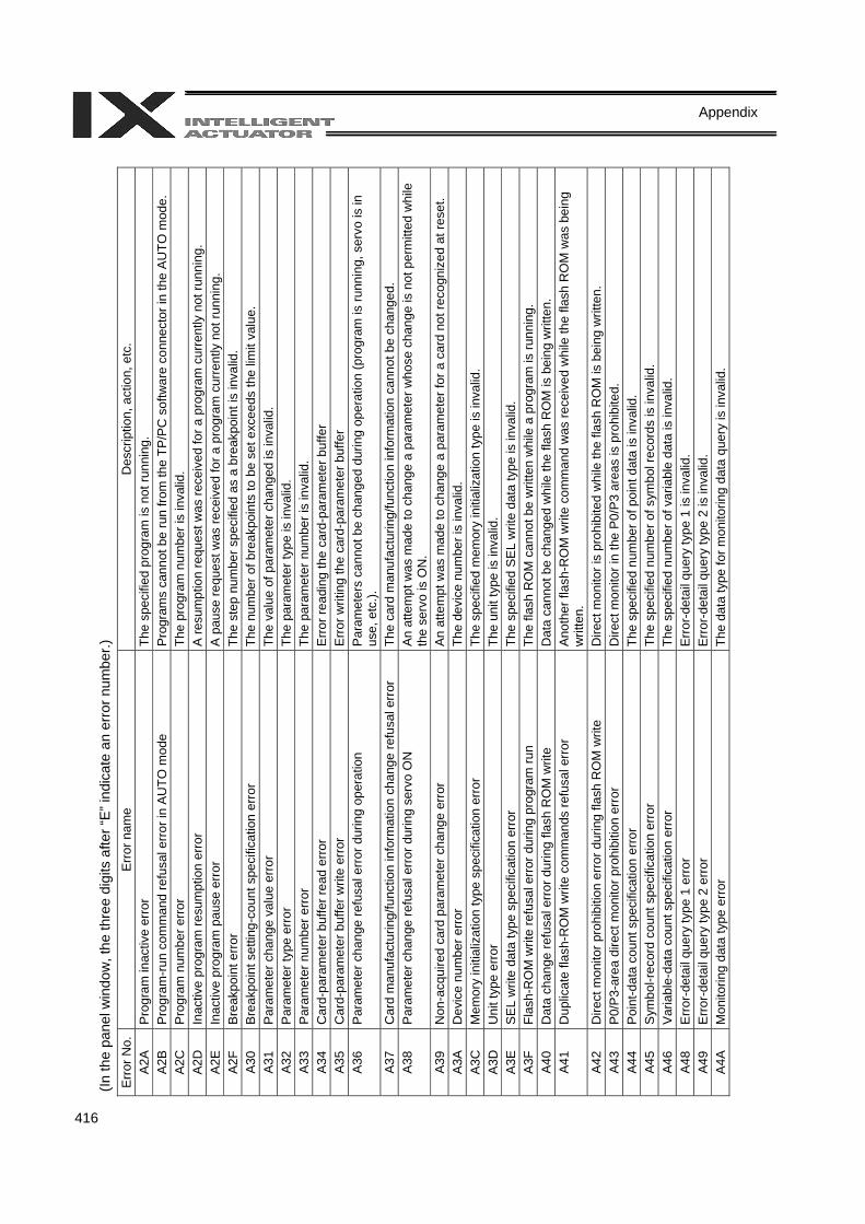
416
Appendix
(In th
e pa
nel w
indo
w, t
he th
ree
digi
ts a
fter “
E” in
dica
te a
n er
ror n
umbe
r.)
Err
or N
o.
Err
or n
ame
Des
crip
tion,
act
ion,
etc
. A
2A
Pro
gram
inac
tive
erro
r Th
e sp
ecifi
ed p
rogr
am is
not
runn
ing.
A
2B
Pro
gram
-run
com
man
d re
fusa
l err
or in
AU
TO m
ode
Pro
gram
s ca
nnot
be
run
from
the
TP/P
C s
oftw
are
conn
ecto
r in
the
AU
TO m
ode.
A
2C
Pro
gram
num
ber e
rror
The
prog
ram
num
ber i
s in
valid
. A
2D
Inac
tive
prog
ram
resu
mpt
ion
erro
r A
resu
mpt
ion
requ
est w
as re
ceiv
ed fo
r a p
rogr
am c
urre
ntly
not
runn
ing.
A
2E
Inac
tive
prog
ram
pau
se e
rror
A
pau
se re
ques
t was
rece
ived
for a
pro
gram
cur
rent
ly n
ot ru
nnin
g.
A2F
B
reak
poin
t err
or
The
step
num
ber s
peci
fied
as a
bre
akpo
int i
s in
valid
. A
30
Bre
akpo
int s
ettin
g-co
unt s
peci
ficat
ion
erro
r Th
e nu
mbe
r of b
reak
poin
ts to
be
set e
xcee
ds th
e lim
it va
lue.
A
31
Par
amet
er c
hang
e va
lue
erro
r Th
e va
lue
of p
aram
eter
cha
nged
is in
valid
. A
32
Par
amet
er ty
pe e
rror
Th
e pa
ram
eter
type
is in
valid
. A
33
Par
amet
er n
umbe
r erro
r Th
e pa
ram
eter
num
ber i
s in
valid
. A
34
Car
d-pa
ram
eter
buf
fer r
ead
erro
r E
rror r
eadi
ng th
e ca
rd-p
aram
eter
buf
fer
A35
C
ard-
para
met
er b
uffe
r writ
e er
ror
Erro
r writ
ing
the
card
-par
amet
er b
uffe
r A
36
Par
amet
er c
hang
e re
fusa
l err
or d
urin
g op
erat
ion
Par
amet
ers
cann
ot b
e ch
ange
d du
ring
oper
atio
n (p
rogr
am is
runn
ing,
ser
vo is
in
use,
etc
.).
A37
C
ard
man
ufac
turin
g/fu
nctio
n in
form
atio
n ch
ange
refu
sal e
rror
Th
e ca
rd m
anuf
actu
ring/
func
tion
info
rmat
ion
cann
ot b
e ch
ange
d.
A38
P
aram
eter
cha
nge
refu
sal e
rror
dur
ing
serv
o O
N
An
atte
mpt
was
mad
e to
cha
nge
a pa
ram
eter
who
se c
hang
e is
not
per
mitt
ed w
hile
th
e se
rvo
is O
N.
A39
N
on-a
cqui
red
card
par
amet
er c
hang
e er
ror
An
atte
mpt
was
mad
e to
cha
nge
a pa
ram
eter
for a
car
d no
t rec
ogni
zed
at re
set.
A3A
D
evic
e nu
mbe
r err
or
The
devi
ce n
umbe
r is
inva
lid.
A3C
M
emor
y in
itial
izat
ion
type
spe
cific
atio
n er
ror
The
spec
ified
mem
ory
initi
aliz
atio
n ty
pe is
inva
lid.
A3D
U
nit t
ype
erro
r Th
e un
it ty
pe is
inva
lid.
A3E
S
EL w
rite
data
type
spe
cific
atio
n er
ror
The
spec
ified
SE
L w
rite
data
type
is in
valid
. A
3F
Flas
h-R
OM
writ
e re
fusa
l err
or d
urin
g pr
ogra
m ru
n Th
e fla
sh R
OM
can
not b
e w
ritte
n w
hile
a p
rogr
am is
runn
ing.
A
40
Dat
a ch
ange
refu
sal e
rror
dur
ing
flash
RO
M w
rite
Dat
a ca
nnot
be
chan
ged
whi
le th
e fla
sh R
OM
is b
eing
writ
ten.
A
41
Dup
licat
e fla
sh-R
OM
writ
e co
mm
ands
refu
sal e
rror
A
noth
er fl
ash-
RO
M w
rite
com
man
d w
as re
ceiv
ed w
hile
the
flash
RO
M w
as b
eing
w
ritte
n.
A42
D
irect
mon
itor p
rohi
bitio
n er
ror d
urin
g fla
sh R
OM
writ
e D
irect
mon
itor i
s pr
ohib
ited
whi
le th
e fla
sh R
OM
is b
eing
writ
ten.
A
43
P0/
P3-
area
dire
ct m
onito
r pro
hibi
tion
erro
r D
irect
mon
itor i
n th
e P
0/P
3 ar
eas
is p
rohi
bite
d.
A44
P
oint
-dat
a co
unt s
peci
ficat
ion
erro
r Th
e sp
ecifi
ed n
umbe
r of p
oint
dat
a is
inva
lid.
A45
S
ymbo
l-rec
ord
coun
t spe
cific
atio
n er
ror
The
spec
ified
num
ber o
f sym
bol r
ecor
ds is
inva
lid.
A46
V
aria
ble-
data
cou
nt s
peci
ficat
ion
erro
r Th
e sp
ecifi
ed n
umbe
r of v
aria
ble
data
is in
valid
. A
48
Erro
r-det
ail q
uery
type
1 e
rror
Erro
r-det
ail q
uery
type
1 is
inva
lid.
A49
E
rror-d
etai
l que
ry ty
pe 2
erro
r E
rror-d
etai
l que
ry ty
pe 2
is in
valid
. A
4A
Mon
itorin
g da
ta ty
pe e
rror
Th
e da
ta ty
pe fo
r mon
itorin
g da
ta q
uery
is in
valid
.
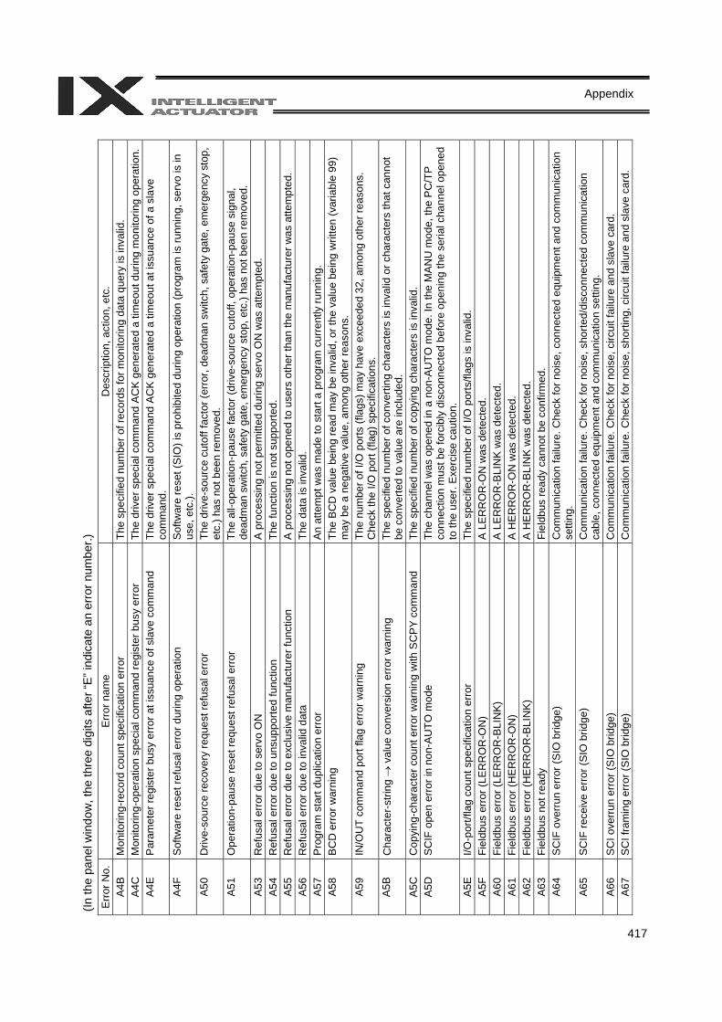
417
Appendix
(In th
e pa
nel w
indo
w, t
he th
ree
digi
ts a
fter “
E” in
dica
te a
n er
ror n
umbe
r.)
Err
or N
o.
Err
or n
ame
Des
crip
tion,
act
ion,
etc
. A
4B
Mon
itorin
g-re
cord
cou
nt s
peci
ficat
ion
erro
r Th
e sp
ecifi
ed n
umbe
r of r
ecor
ds fo
r mon
itorin
g da
ta q
uery
is in
valid
. A
4C
Mon
itorin
g-op
erat
ion
spec
ial c
omm
and
regi
ster
bus
y er
ror
The
driv
er s
peci
al c
omm
and
AC
K g
ener
ated
a ti
meo
ut d
urin
g m
onito
ring
oper
atio
n.
A4E
P
aram
eter
regi
ster
bus
y er
ror a
t iss
uanc
e of
sla
ve c
omm
and
The
driv
er s
peci
al c
omm
and
AC
K g
ener
ated
a ti
meo
ut a
t iss
uanc
e of
a s
lave
co
mm
and.
A
4F
Sof
twar
e re
set r
efus
al e
rror d
urin
g op
erat
ion
Sof
twar
e re
set (
SIO
) is
proh
ibite
d du
ring
oper
atio
n (p
rogr
am is
runn
ing,
ser
vo is
in
use,
etc
.).
A50
D
rive-
sour
ce re
cove
ry re
ques
t ref
usal
err
or
The
driv
e-so
urce
cut
off f
acto
r (er
ror,
dead
man
sw
itch,
saf
ety
gate
, em
erge
ncy
stop
, et
c.) h
as n
ot b
een
rem
oved
. A
51
Ope
ratio
n-pa
use
rese
t req
uest
refu
sal e
rror
The
all-o
pera
tion-
paus
e fa
ctor
(driv
e-so
urce
cut
off,
oper
atio
n-pa
use
sign
al,
dead
man
sw
itch,
saf
ety
gate
, em
erge
ncy
stop
, etc
.) ha
s no
t bee
n re
mov
ed.
A53
R
efus
al e
rror
due
to s
ervo
ON
A
pro
cess
ing
not p
erm
itted
dur
ing
serv
o O
N w
as a
ttem
pted
. A
54
Ref
usal
err
or d
ue to
uns
uppo
rted
func
tion
The
func
tion
is n
ot s
uppo
rted.
A
55
Ref
usal
erro
r due
to e
xclu
sive
man
ufac
ture
r fun
ctio
n A
pro
cess
ing
not o
pene
d to
use
rs o
ther
than
the
man
ufac
ture
r was
atte
mpt
ed.
A56
Ref
usal
err
or d
ue to
inva
lid d
ata
The
data
is in
valid
. A
57
Pro
gram
sta
rt du
plic
atio
n er
ror
An
atte
mpt
was
mad
e to
sta
rt a
prog
ram
cur
rent
ly ru
nnin
g.
A58
B
CD
erro
r war
ning
Th
e B
CD
val
ue b
eing
read
may
be
inva
lid, o
r the
val
ue b
eing
writ
ten
(var
iabl
e 99
) m
ay b
e a
nega
tive
valu
e, a
mon
g ot
her r
easo
ns.
A59
IN
/OU
T co
mm
and
port
flag
erro
r war
ning
Th
e nu
mbe
r of I
/O p
orts
(fla
gs) m
ay h
ave
exce
eded
32,
am
ong
othe
r rea
sons
. C
heck
the
I/O p
ort (
flag)
spe
cific
atio
ns.
A5B
C
hara
cter
-stri
ng →
val
ue c
onve
rsio
n er
ror w
arni
ng
The
spec
ified
num
ber o
f con
verti
ng c
hara
cter
s is
inva
lid o
r cha
ract
ers
that
can
not
be c
onve
rted
to v
alue
are
incl
uded
. A
5C
Cop
ying
-cha
ract
er c
ount
erro
r war
ning
with
SC
PY
com
man
d Th
e sp
ecifi
ed n
umbe
r of c
opyi
ng c
hara
cter
s is
inva
lid.
A5D
S
CIF
ope
n er
ror i
n no
n-A
UTO
mod
e Th
e ch
anne
l was
ope
ned
in a
non
-AU
TO m
ode.
In th
e M
AN
U m
ode,
the
PC
/TP
conn
ectio
n m
ust b
e fo
rcib
ly d
isco
nnec
ted
befo
re o
peni
ng th
e se
rial c
hann
el o
pene
d to
the
user
. Exe
rcis
e ca
utio
n.
A5E
I/O
-por
t/fla
g co
unt s
peci
ficat
ion
erro
r Th
e sp
ecifi
ed n
umbe
r of I
/O p
orts
/flag
s is
inva
lid.
A5F
Fi
eldb
us e
rror
(LER
RO
R-O
N)
A LE
RR
OR
-ON
was
det
ecte
d.
A60
Fiel
dbus
err
or (L
ERR
OR
-BLI
NK)
A
LER
RO
R-B
LIN
K w
as d
etec
ted.
A6
1 Fi
eldb
us e
rror
(HE
RR
OR
-ON
) A
HER
RO
R-O
N w
as d
etec
ted.
A6
2 Fi
eldb
us e
rror
(HE
RR
OR
-BLI
NK)
A
HER
RO
R-B
LIN
K w
as d
etec
ted.
A
63
Fiel
dbus
not
read
y Fi
eldb
us re
ady
cann
ot b
e co
nfirm
ed.
A64
S
CIF
ove
rrun
erro
r (S
IO b
ridge
) C
omm
unic
atio
n fa
ilure
. Che
ck fo
r noi
se, c
onne
cted
equ
ipm
ent a
nd c
omm
unic
atio
n se
tting
. A
65
SC
IF re
ceiv
e er
ror (
SIO
brid
ge)
Com
mun
icat
ion
failu
re. C
heck
for n
oise
, sho
rted/
disc
onne
cted
com
mun
icat
ion
cabl
e, c
onne
cted
equ
ipm
ent a
nd c
omm
unic
atio
n se
tting
. A
66
SC
I ove
rrun
erro
r (S
IO b
ridge
) C
omm
unic
atio
n fa
ilure
. Che
ck fo
r noi
se, c
ircui
t fai
lure
and
sla
ve c
ard.
A
67
SC
I fra
min
g er
ror (
SIO
brid
ge)
Com
mun
icat
ion
failu
re. C
heck
for n
oise
, sho
rting
, circ
uit f
ailu
re a
nd s
lave
car
d.
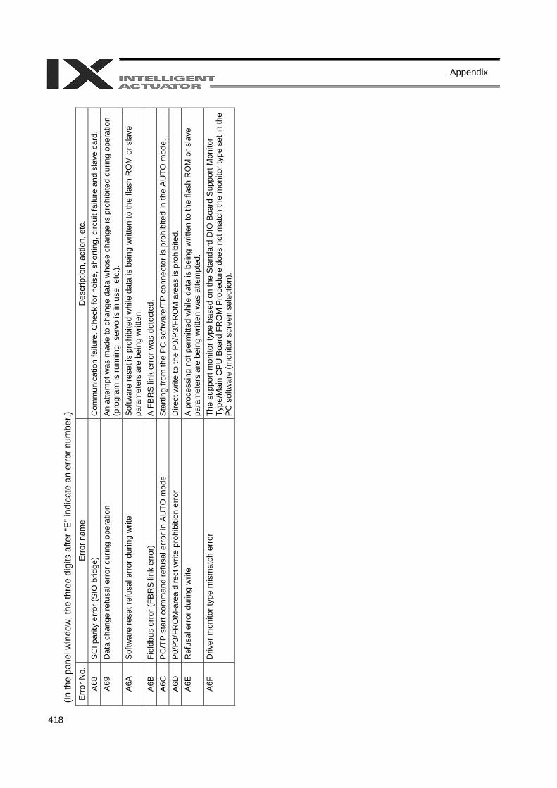
418
Appendix
(In th
e pa
nel w
indo
w, t
he th
ree
digi
ts a
fter “
E” in
dica
te a
n er
ror n
umbe
r.)
Err
or N
o.
Err
or n
ame
Des
crip
tion,
act
ion,
etc
. A
68
SC
I par
ity e
rror (
SIO
brid
ge)
Com
mun
icat
ion
failu
re. C
heck
for n
oise
, sho
rting
, circ
uit f
ailu
re a
nd s
lave
car
d.
A69
D
ata
chan
ge re
fusa
l err
or d
urin
g op
erat
ion
An
atte
mpt
was
mad
e to
cha
nge
data
who
se c
hang
e is
pro
hibi
ted
durin
g op
erat
ion
(pro
gram
is ru
nnin
g, s
ervo
is in
use
, etc
.).
A6A
S
oftw
are
rese
t ref
usal
erro
r dur
ing
writ
e S
oftw
are
rese
t is
proh
ibite
d w
hile
dat
a is
bei
ng w
ritte
n to
the
flash
RO
M o
r sla
ve
para
met
ers
are
bein
g w
ritte
n.
A6B
Fi
eldb
us e
rror (
FBR
S li
nk e
rror)
A F
BR
S li
nk e
rror w
as d
etec
ted.
A
6C
PC
/TP
star
t com
man
d re
fusa
l erro
r in
AU
TO m
ode
Sta
rting
from
the
PC
sof
twar
e/TP
con
nect
or is
pro
hibi
ted
in th
e A
UTO
mod
e.
A6D
P
0/P
3/FR
OM
-are
a di
rect
writ
e pr
ohib
ition
erro
r D
irect
writ
e to
the
P0/
P3/
FRO
M a
reas
is p
rohi
bite
d.
A6E
R
efus
al e
rror d
urin
g w
rite
A p
roce
ssin
g no
t per
mitt
ed w
hile
dat
a is
bei
ng w
ritte
n to
the
flash
RO
M o
r sla
ve
para
met
ers
are
bein
g w
ritte
n w
as a
ttem
pted
. A
6F
Driv
er m
onito
r typ
e m
ism
atch
err
or
The
supp
ort m
onito
r typ
e ba
sed
on th
e S
tand
ard
DIO
Boa
rd S
uppo
rt M
onito
r Ty
pe/M
ain
CP
U B
oard
FR
OM
Pro
cedu
re d
oes
not m
atch
the
mon
itor t
ype
set i
n th
e P
C s
oftw
are
(mon
itor s
cree
n se
lect
ion)
.
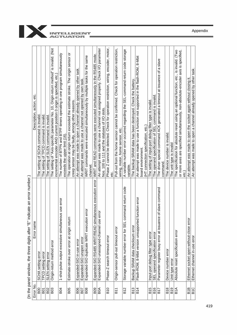
419
Appendix
(In th
e pa
nel w
indo
w, t
he th
ree
digi
ts a
fter “
E” in
dica
te a
n er
ror n
umbe
r.)
Err
or N
o.
Err
or n
ame
Des
crip
tion,
act
ion,
etc
. B
00
SC
HA
set
ting
erro
r Th
e se
tting
of S
CH
A c
omm
and
is in
valid
. B
01
TPC
D s
ettin
g er
ror
The
setti
ng o
f TPC
D c
omm
and
is in
valid
. B
02
SLE
N s
ettin
g er
ror
The
setti
ng o
f SLE
N c
omm
and
is in
valid
. B
03
Orig
in-r
etur
n m
etho
d er
ror
The
setti
ng o
f “A
xis-
spec
ific
para
met
er N
o. 1
0, O
rigin
-retu
rn m
etho
d” is
inva
lid. (
Not
in
crem
enta
l enc
oder
AN
D c
urre
nt p
ositi
on 0
orig
in is
spe
cifie
d, e
tc.)
B04
1-
shot
-pul
se o
utpu
t exc
essi
ve s
imul
tane
ous
use
erro
r Th
e nu
mbe
r of B
TPN
and
BTP
F tim
ers
oper
atin
g in
one
pro
gram
sim
ulta
neou
sly
exce
eds
the
uppe
r lim
it (1
6).
B05
E
stim
ate-
stro
ke o
ver e
rror a
t orig
in re
turn
Th
e op
erat
ion
at o
rigin
retu
rn e
xcee
ded
the
estim
ate
stro
ke. T
he o
rigin
sen
sor o
r cr
eep
sens
or m
ay b
e fa
ulty
, am
ong
othe
r rea
sons
. B
06
Exp
ande
d-S
IO in
-use
err
or
An
atte
mpt
was
mad
e to
ope
n a
chan
nel a
lread
y op
ened
by
othe
r tas
k.
B07
E
xpan
ded-
SIO
uno
pen
erro
r A
n at
tem
pt w
as m
ade
to u
se a
cha
nnel
not
ope
ned
by o
wn
task
. B
08
Exp
ande
d-S
IO d
uplic
ate
WR
IT e
xecu
tion
erro
r W
RIT
com
man
ds w
ere
exec
uted
sim
ulta
neou
sly
by m
ultip
le ta
sks
for t
he s
ame
chan
nel.
B09
E
xpan
ded-
SIO
RS
485
WR
IT/R
EA
D s
imul
tane
ous
exec
utio
n er
ror
WR
IT a
nd R
EA
D c
omm
ands
wer
e ex
ecut
ed s
imul
tane
ousl
y in
the
RS
485
mod
e.
B0A
E
xpan
ded-
SIO
una
ssig
ned-
chan
nel u
se e
rror
A
n at
tem
pt w
as m
ade
to u
se a
cha
nnel
not
ass
igne
d pr
oper
ly. C
heck
I/O
par
amet
er
Nos
. 100
to 1
11 a
nd th
e st
atus
es o
f I/O
slo
ts.
B10
P
hase
-Z s
earc
h tim
eout
err
or
Pha
se Z
can
not b
e de
tect
ed. C
heck
for o
pera
tion
rest
rictio
n, w
iring
, enc
oder
, mot
or,
etc.
B
11
Orig
in-s
enso
r pul
l-out
tim
eout
erro
r P
ull-o
ut fr
om th
e ho
me
sens
or c
anno
t be
conf
irmed
. Che
ck fo
r ope
ratio
n re
stric
tion,
w
iring
, mot
or, h
ome
sens
or, e
tc.
B12
S
tora
ge v
aria
ble
num
ber e
rror
for S
EL
com
man
d re
turn
cod
e A
var
iabl
e nu
mbe
r erro
r occ
urre
d re
gard
ing
the
SE
L-co
mm
and
retu
rn c
ode
stor
age
varia
ble.
B
13
Bac
kup
SR
AM
dat
a ch
ecks
um e
rror
Th
e ba
ckup
SR
AM
dat
a ha
s be
en d
estro
yed.
Che
ck th
e ba
ttery
. B
14
Flas
h-R
OM
, 8-M
bit v
ersi
on u
nsup
porte
d fu
nctio
n er
ror
An
atte
mpt
was
mad
e to
use
a fu
nctio
n no
t sup
porte
d in
the
flash
-RO
M, 8
-Mbi
t bo
ard
envi
ronm
ent.
(HT
conn
ectio
n sp
ecifi
catio
n, e
tc.)
B15
In
put-p
ort d
ebug
filte
r typ
e er
ror
The
setti
ng o
f inp
ut-p
ort d
ebug
filte
r typ
e is
inva
lid.
B16
S
EL o
pera
nd s
peci
ficat
ion
erro
r Th
e op
eran
d sp
ecifi
catio
n of
SE
L co
mm
and
is in
valid
. B
17
Par
amet
er re
gist
er b
usy
erro
r at i
ssua
nce
of s
lave
com
man
d Th
e dr
iver
spe
cial
com
man
d A
CK
gen
erat
ed a
tim
eout
at i
ssua
nce
of a
sla
ve
com
man
d.
B18
D
evic
e nu
mbe
r err
or
The
devi
ce n
umbe
r is
inva
lid.
B19
U
nit t
ype
erro
r Th
e un
it ty
pe is
inva
lid
B1A
A
bsol
ute
rese
t spe
cific
atio
n er
ror
The
spec
ifica
tion
for a
bsol
ute
rese
t usi
ng a
n op
tiona
l fun
ctio
n, e
tc.,
is in
valid
. (Tw
o or
mor
e ax
es a
re s
peci
fied
sim
ulta
neou
sly,
non
-abs
olut
e-en
code
r axi
s is
spe
cifie
d,
etc.
) B
1B
Eth
erne
t soc
ket o
pen-
with
out-c
lose
err
or
An
atte
mpt
was
mad
e to
ope
n th
e so
cket
aga
in w
ithou
t clo
sing
it.
B1C
E
ther
net c
hann
el in
-use
err
or
An
atte
mpt
was
mad
e to
ope
n a
chan
nel a
lread
y op
ened
by
othe
r tas
k.
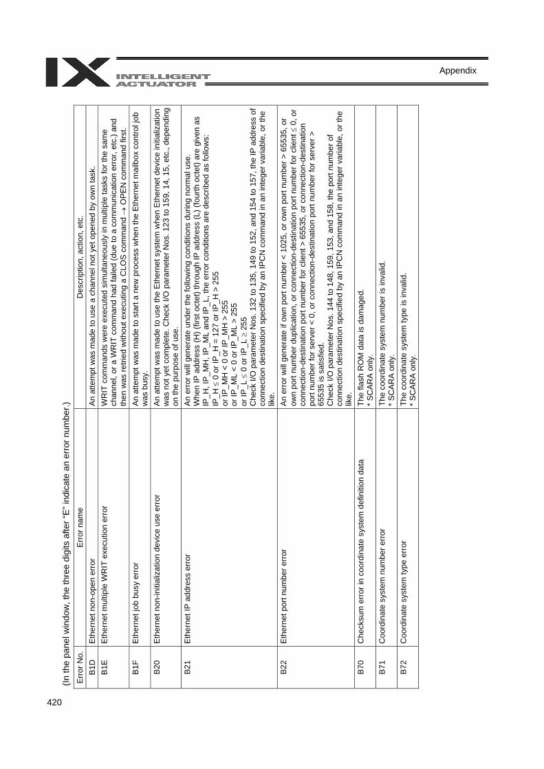
420
Appendix
(In th
e pa
nel w
indo
w, t
he th
ree
digi
ts a
fter “
E” in
dica
te a
n er
ror n
umbe
r.)
Err
or N
o.
Err
or n
ame
Des
crip
tion,
act
ion,
etc
. B
1D
Eth
erne
t non
-ope
n er
ror
An
atte
mpt
was
mad
e to
use
a c
hann
el n
ot y
et o
pene
d by
ow
n ta
sk.
B1E
E
ther
net m
ultip
le W
RIT
exe
cutio
n er
ror
WR
IT c
omm
ands
wer
e ex
ecut
ed s
imul
tane
ousl
y in
mul
tiple
task
s fo
r the
sam
e ch
anne
l, or
a W
RIT
com
man
d ha
d fa
iled
(due
to a
com
mun
icat
ion
erro
r, et
c.) a
nd
then
was
retri
ed w
ithou
t exe
cutin
g a
CLO
S c
omm
and →
OPE
N c
omm
and
first
. B
1F
Eth
erne
t job
bus
y er
ror
An
atte
mpt
was
mad
e to
sta
rt a
new
pro
cess
whe
n th
e E
ther
net m
ailb
ox c
ontro
l job
w
as b
usy.
B
20
Eth
erne
t non
-initi
aliz
atio
n de
vice
use
err
or
An
atte
mpt
was
mad
e to
use
the
Eth
erne
t sys
tem
whe
n E
ther
net d
evic
e in
itial
izat
ion
was
not
yet
com
plet
e. C
heck
I/O
par
amet
er N
os. 1
23 to
159
, 14,
15,
etc
., de
pend
ing
on th
e pu
rpos
e of
use
. B
21
Eth
erne
t IP
add
ress
err
or
An
erro
r will
gen
erat
e un
der t
he fo
llow
ing
cond
ition
s du
ring
norm
al u
se.
Whe
n IP
add
ress
(H) (
first
oct
et) t
hrou
gh IP
add
ress
(L) (
four
th o
ctet
) are
giv
en a
s IP
_H, I
P_M
H, I
P_M
L an
d IP
_L, t
he e
rror
con
ditio
ns a
re d
escr
ibed
as
follo
ws:
IP
_H ≤
0 o
r IP
_H =
127
or I
P_H
> 2
55
or IP
_MH
< 0
or I
P_M
H >
255
or
IP_M
L <
0 or
IP_M
L >
255
or IP
_L ≤
0 o
r IP_
L ≥
255
Che
ck I/
O p
aram
eter
Nos
. 132
to 1
35, 1
49 to
152
, and
154
to 1
57, t
he IP
add
ress
of
conn
ectio
n de
stin
atio
n sp
ecifi
ed b
y an
IPC
N c
omm
and
in a
n in
tege
r var
iabl
e, o
r the
lik
e.
B22
E
ther
net p
ort n
umbe
r err
or
An
erro
r will
gene
rate
if o
wn
port
num
ber <
102
5, o
r ow
n po
rt nu
mbe
r > 6
5535
, or
own
port
num
ber d
uplic
atio
n, o
r con
nect
ion-
dest
inat
ion
port
num
ber f
or c
lient
≤ 0
, or
conn
ectio
n-de
stin
atio
n po
rt nu
mbe
r for
clie
nt >
655
35, o
r con
nect
ion-
dest
inat
ion
port
num
ber f
or s
erve
r < 0
, or c
onne
ctio
n-de
stin
atio
n po
rt nu
mbe
r for
ser
ver >
65
535
is s
atis
fied.
C
heck
I/O
par
amet
er N
os. 1
44 to
148
, 159
, 153
, and
158
, the
por
t num
ber o
f co
nnec
tion
dest
inat
ion
spec
ified
by
an IP
CN
com
man
d in
an
inte
ger v
aria
ble,
or t
he
like.
B
70
Che
cksu
m e
rror
in c
oord
inat
e sy
stem
def
initi
on d
ata
The
flash
RO
M d
ata
is d
amag
ed.
* S
CA
RA
onl
y.
B71
C
oord
inat
e sy
stem
num
ber e
rror
Th
e co
ordi
nate
sys
tem
num
ber i
s in
valid
. *
SC
AR
A o
nly.
B
72
Coo
rdin
ate
syst
em ty
pe e
rror
Th
e co
ordi
nate
sys
tem
type
is in
valid
. *
SC
AR
A o
nly.

421
Appendix
(In th
e pa
nel w
indo
w, t
he th
ree
digi
ts a
fter “
E” in
dica
te a
n er
ror n
umbe
r.)
Err
or N
o.
Err
or n
ame
Des
crip
tion,
act
ion,
etc
. B
73
Erro
r due
to p
rohi
bitio
n of
cha
nge
of c
oord
inat
e sy
stem
dat
a us
ed
by s
ervo
C
hang
ing
of c
oord
inat
e sy
stem
dat
a cu
rren
tly u
sed
by th
e se
rvo
syst
em is
pr
ohib
ited.
*
SC
AR
A o
nly.
B
74
CP
-ope
ratio
n re
stric
tion
zone
ent
ry e
rror
(PTP
/jogg
ing
of e
ach
axis
ena
bled
) E
ntry
into
the
CP
-ope
ratio
n re
stric
tion
zone
was
det
ecte
d. P
TP o
pera
tion
and
jogg
ing
oper
atio
n of
eac
h ax
is a
re e
nabl
ed.
* S
CA
RA
onl
y.
B75
S
ingu
lar-
poin
t cal
cula
tion
erro
r C
P c
alcu
latio
n ca
nnot
be
perfo
rmed
due
to th
e si
ngul
ar p
oint
. Che
ck fo
r inv
alid
co
ordi
nate
cau
sed
by a
n in
appr
opria
te o
rigin
of a
rm 2
, etc
. *
SC
AR
A o
nly.
B
77
Cur
rent
arm
sys
tem
set
ting
erro
r Th
e ta
rget
arm
sys
tem
to b
e se
t doe
s no
t mat
ch th
e ac
tual
ang
le o
f arm
2, o
r co
ordi
nate
s ar
e no
t yet
det
erm
ined
. *
SC
AR
A o
nly.
B
78
Cur
rent
arm
sys
tem
inde
term
inat
ion
erro
r Th
e cu
rren
t arm
sys
tem
is in
dete
rmin
able
. *
SC
AR
A o
nly.
B
79
R-a
xis
serv
o O
FF d
etec
tion
erro
r dur
ing
posi
tion
cont
rol
corre
ctio
n R
-axi
s se
rvo
OFF
was
det
ecte
d du
ring
posi
tion
cont
rol c
orre
ctio
n.
* S
CA
RA
onl
y.
B7A
Z-
axis
ser
vo O
FF d
etec
tion
erro
r dur
ing
RZ
mec
hani
sm
corre
ctio
n Z-
axis
ser
vo O
FF w
as d
etec
ted
durin
g R
Z m
echa
nism
cor
rect
ion.
*
SC
AR
A o
nly.
B
7B
Erro
r due
to ta
rget
locu
s in
side
rear
ent
ry p
rohi
bitio
n ar
ea
The
targ
et p
ositi
on o
r mov
emen
t loc
us is
insi
de th
e re
ar e
ntry
pro
hibi
tion
area
. *
SC
AR
A o
nly.
B
7C
Erro
r due
to ta
rget
locu
s in
side
CP
-ope
ratio
n re
stric
tion
zone
(P
TP/jo
ggin
g of
eac
h ax
is e
nabl
ed)
The
targ
et p
ositi
on o
r mov
emen
t loc
us is
insi
de C
P-o
pera
tion
rest
rictio
n zo
ne. P
TP
oper
atio
n an
d jo
ggin
g op
erat
ion
of e
ach
axis
are
ena
bled
. *
SC
AR
A o
nly.
B
7D
Phy
sica
lly u
nrea
lizab
le ta
rget
err
or
The
spec
ified
targ
et is
unr
ealiz
able
bas
ed o
n th
e ar
m le
ngth
com
posi
tion
of a
xes
1 an
d 2.
Che
ck "A
xis-
spec
ific
para
met
er N
o. 1
38, A
rm le
ngth
" and
the
targ
et v
alue
. *
SC
AR
A o
nly.
B
7F
Ser
vo u
se p
urpo
se e
rror
Th
e us
e pu
rpos
e of
ser
vo is
inva
lid.
* S
CA
RA
onl
y.
B80
S
peci
ficat
ion-
proh
ibite
d ax
is e
rror
Spe
cific
atio
n of
the
axis
is p
rohi
bite
d. S
et a
n ax
is th
at c
an b
e sp
ecifi
ed.
* S
CA
RA
onl
y.
B81
Axi
s-sp
ecifi
c P
TP m
ultip
le-a
xis
spec
ifica
tion
erro
r Ax
is-s
peci
fic P
TP o
pera
tion
was
spe
cifie
d fo
r mul
tiple
axe
s. A
xis-
spec
ific
PTP
op
erat
ion
can
be s
peci
fied
only
for a
sin
gle
axis
. *
SC
AR
A o
nly.
B
82
Jogg
ing
mul
tiple
-axi
s sp
ecifi
catio
n er
ror
Jogg
ing/
inch
ing
was
spe
cifie
d fo
r mul
tiple
axe
s. J
oggi
ng/in
chin
g ca
n be
spe
cifie
d on
ly fo
r a s
ingl
e ax
is.
* S
CA
RA
onl
y.
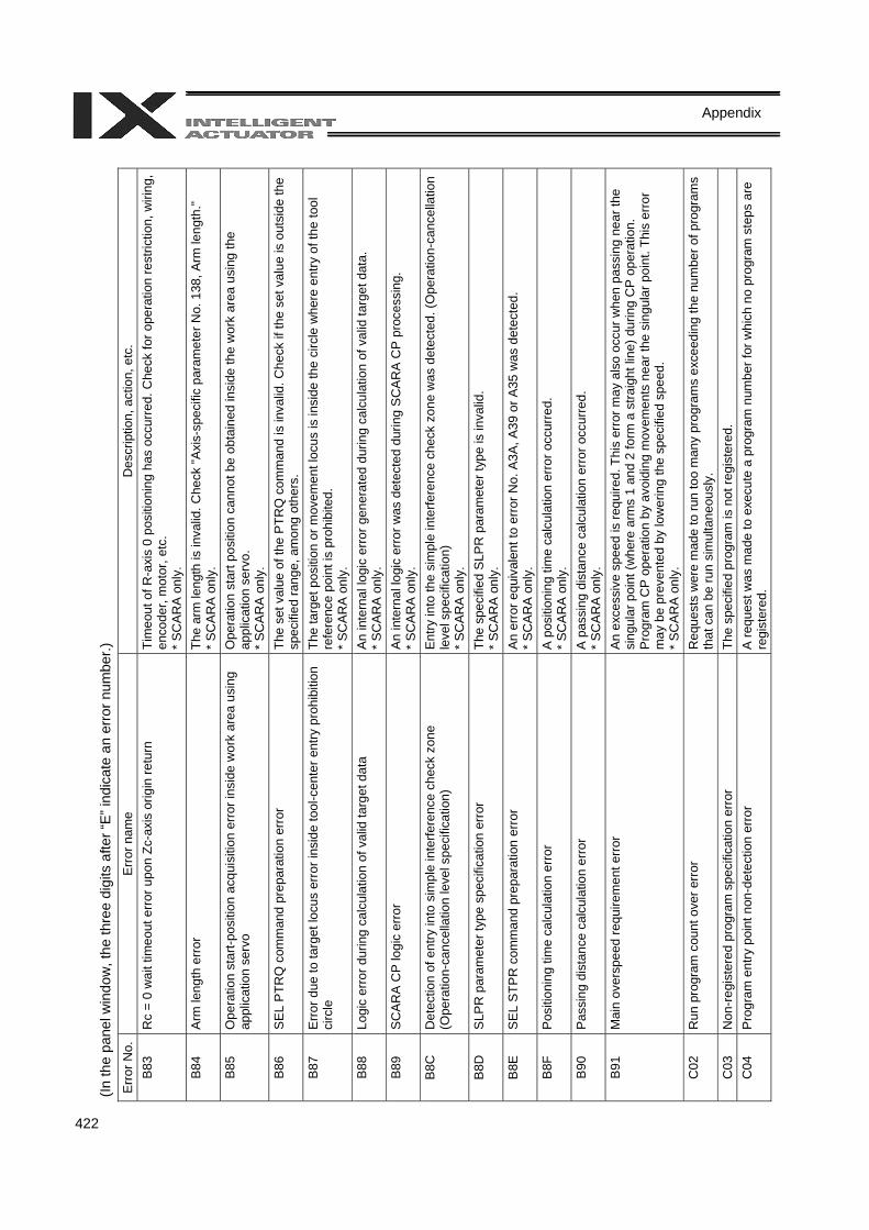
422
Appendix
(In th
e pa
nel w
indo
w, t
he th
ree
digi
ts a
fter “
E” in
dica
te a
n er
ror n
umbe
r.)
Err
or N
o.
Err
or n
ame
Des
crip
tion,
act
ion,
etc
. B
83
Rc
= 0
wai
t tim
eout
err
or u
pon
Zc-a
xis
orig
in re
turn
Ti
meo
ut o
f R-a
xis
0 po
sitio
ning
has
occ
urre
d. C
heck
for o
pera
tion
rest
rictio
n, w
iring
, en
code
r, m
otor
, etc
. *
SC
AR
A o
nly.
B
84
Arm
leng
th e
rror
Th
e ar
m le
ngth
is in
valid
. Che
ck "A
xis-
spec
ific
para
met
er N
o. 1
38, A
rm le
ngth
."
* S
CA
RA
onl
y.
B85
O
pera
tion
star
t-pos
ition
acq
uisi
tion
erro
r ins
ide
wor
k ar
ea u
sing
ap
plic
atio
n se
rvo
Ope
ratio
n st
art p
ositi
on c
anno
t be
obta
ined
insi
de th
e w
ork
area
usi
ng th
e ap
plic
atio
n se
rvo.
*
SC
AR
A o
nly.
B
86
SEL
PTR
Q c
omm
and
prep
arat
ion
erro
r Th
e se
t val
ue o
f the
PTR
Q c
omm
and
is in
valid
. Che
ck if
the
set v
alue
is o
utsi
de th
e sp
ecifi
ed ra
nge,
am
ong
othe
rs.
B87
E
rror d
ue to
targ
et lo
cus
erro
r ins
ide
tool
-cen
ter e
ntry
pro
hibi
tion
circ
le
The
targ
et p
ositi
on o
r mov
emen
t loc
us is
insi
de th
e ci
rcle
whe
re e
ntry
of t
he to
ol
refe
renc
e po
int i
s pr
ohib
ited.
*
SC
AR
A o
nly.
B
88
Logi
c er
ror d
urin
g ca
lcul
atio
n of
val
id ta
rget
dat
a A
n in
tern
al lo
gic
erro
r gen
erat
ed d
urin
g ca
lcul
atio
n of
val
id ta
rget
dat
a.
* S
CA
RA
onl
y.
B89
S
CA
RA
CP
logi
c er
ror
An
inte
rnal
logi
c er
ror w
as d
etec
ted
durin
g S
CA
RA
CP
pro
cess
ing.
*
SC
AR
A o
nly.
B
8C
Det
ectio
n of
ent
ry in
to s
impl
e in
terfe
renc
e ch
eck
zone
(O
pera
tion-
canc
ella
tion
leve
l spe
cific
atio
n)
Ent
ry in
to th
e si
mpl
e in
terfe
renc
e ch
eck
zone
was
det
ecte
d. (O
pera
tion-
canc
ella
tion
leve
l spe
cific
atio
n)
* S
CA
RA
onl
y.
B8D
S
LPR
par
amet
er ty
pe s
peci
ficat
ion
erro
r Th
e sp
ecifi
ed S
LPR
par
amet
er ty
pe is
inva
lid.
* S
CA
RA
onl
y.
B8E
S
EL S
TPR
com
man
d pr
epar
atio
n er
ror
An
erro
r equ
ival
ent t
o er
ror N
o. A
3A, A
39 o
r A35
was
det
ecte
d.
* S
CA
RA
onl
y.
B8F
P
ositi
onin
g tim
e ca
lcul
atio
n er
ror
A p
ositi
onin
g tim
e ca
lcul
atio
n er
ror o
ccur
red.
*
SC
AR
A o
nly.
B
90
Pas
sing
dis
tanc
e ca
lcul
atio
n er
ror
A p
assi
ng d
ista
nce
calc
ulat
ion
erro
r occ
urre
d.
* S
CA
RA
onl
y.
B91
M
ain
over
spee
d re
quire
men
t erro
r A
n ex
cess
ive
spee
d is
requ
ired.
Thi
s er
ror m
ay a
lso
occu
r whe
n pa
ssin
g ne
ar th
e si
ngul
ar p
oint
(whe
re a
rms
1 an
d 2
form
a s
traig
ht li
ne) d
urin
g C
P o
pera
tion.
P
rogr
am C
P o
pera
tion
by a
void
ing
mov
emen
ts n
ear t
he s
ingu
lar p
oint
. Thi
s er
ror
may
be
prev
ente
d by
low
erin
g th
e sp
ecifi
ed s
peed
. *
SC
AR
A o
nly.
C
02
Run
pro
gram
cou
nt o
ver e
rror
R
eque
sts
wer
e m
ade
to ru
n to
o m
any
prog
ram
s ex
ceed
ing
the
num
ber o
f pro
gram
s th
at c
an b
e ru
n si
mul
tane
ousl
y.
C03
N
on-re
gist
ered
pro
gram
spe
cific
atio
n er
ror
The
spec
ified
pro
gram
is n
ot re
gist
ered
. C
04
Pro
gram
ent
ry p
oint
non
-det
ectio
n er
ror
A re
ques
t was
mad
e to
exe
cute
a p
rogr
am n
umbe
r for
whi
ch n
o pr
ogra
m s
teps
are
re
gist
ered
.
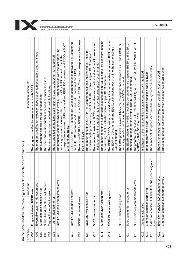
423
Appendix
(In th
e pa
nel w
indo
w, t
he th
ree
digi
ts a
fter “
E” in
dica
te a
n er
ror n
umbe
r.)
Erro
r No.
E
rror
nam
e D
escr
iptio
n, a
ctio
n, e
tc.
C05
P
rogr
am fi
rst-s
tep
BG
SR
err
or
The
prog
ram
spe
cifie
d fo
r exe
cutio
n st
arts
with
BG
SR
. C
06
Exe
cuta
ble
step
non
-det
ectio
n er
ror
The
prog
ram
spe
cifie
d fo
r exe
cutio
n do
es n
ot c
onta
in e
xecu
tabl
e pr
ogra
m s
teps
. C
07
Sub
rout
ine
non-
defin
ition
err
or
The
subr
outin
e sp
ecifi
ed fo
r cal
l is
not d
efin
ed.
C08
S
ubro
utin
e du
plic
ate-
defin
ition
err
or
The
sam
e su
brou
tine
num
ber i
s de
fined
at m
ultip
le lo
catio
ns.
C0A
Ta
g du
plic
ate-
defin
ition
err
or
The
sam
e ta
g nu
mbe
r is
defin
ed a
t mul
tiple
loca
tions
. C
0B
Tag
non-
defin
ition
erro
r Th
e ta
g sp
ecifi
ed a
s th
e ju
mp
dest
inat
ion
of a
GO
TO s
tate
men
t is
not d
efin
ed.
C0C
D
W/IF
/IS/S
L pa
ir-en
d m
ism
atch
erro
r Th
e br
anch
ing
com
man
d sy
ntax
is in
valid
. Cor
resp
onde
nce
with
the
last
app
earin
g br
anch
ing
com
man
d is
inva
lid w
hen
ED
IF, E
DD
O o
r ED
SL
is u
sed.
Che
ck th
e co
rres
pond
ence
bet
wee
n IF
/IS c
omm
and
and
ED
IF, D
O c
omm
and
and
ED
DO
or S
LCT
com
man
d an
d E
DS
L.
C0D
D
W/IF
/IS/S
L no
pai
r-end
erro
r E
DIF
, ED
DO
or E
DS
L is
not
foun
d. C
heck
the
corr
espo
nden
ce b
etw
een
IF/IS
com
man
d an
d E
DIF
, DO
com
man
d an
d E
DD
O o
r SLC
T co
mm
and
and
ED
SL.
C
0E
BG
SR
no
pair-
end
erro
r Th
ere
is n
o E
DS
R fo
r BG
SR
, or n
o B
GS
R fo
r ED
SR
. Che
ck th
e co
rres
pond
ence
bet
wee
n BG
SR a
nd E
DS
R.
C0F
D
O/IF
/IS o
ver-
nest
ing
erro
r Th
e nu
mbe
r of n
ests
in a
DO
or I
F/IS
com
man
d ex
ceed
s th
e lim
it va
lue.
Che
ck fo
r ex
cess
ive
nest
ing
or b
ranc
hing
out
of o
r int
o th
e sy
ntax
usi
ng a
GO
TO c
omm
and.
C
10
SLC
T ov
er-n
estin
g er
ror
The
num
ber o
f nes
ts in
a S
LCT
com
man
d ex
ceed
s th
e lim
it va
lue.
Che
ck fo
r exc
essi
ve
nest
ing
or b
ranc
hing
out
of o
r int
o th
e sy
ntax
usi
ng a
GO
TO c
omm
and.
C
11
Sub
rout
ine
over
-nes
ting
erro
r Th
e nu
mbe
r of n
ests
in a
sub
rout
ine
exce
eds
the
limit
valu
e. C
heck
for e
xces
sive
nes
ting
or b
ranc
hing
out
of o
r int
o th
e sy
ntax
usi
ng a
GO
TO c
omm
and.
C
12
DO
/IF/IS
und
er-n
estin
g er
ror
The
ED
IF o
r ED
DO
pos
ition
is in
valid
. Che
ck th
e co
rres
pond
ence
bet
wee
n IF
/IS c
omm
and
and
ED
IF o
r DO
com
man
d an
d E
DD
O, o
r bra
nchi
ng o
ut o
f or i
nto
the
synt
ax u
sing
a
GO
TO c
omm
and.
C
13
SLC
T un
der-
nest
ing
erro
r Th
e E
DS
L po
sitio
n is
inva
lid. C
heck
the
corr
espo
nden
ce b
etw
een
SLC
T an
d E
DS
R, o
r br
anch
ing
out o
f or i
nto
the
synt
ax u
sing
a G
OTO
com
man
d.
C14
S
ubro
utin
e un
der-n
estin
g er
ror
The
ED
SR
pos
ition
is in
valid
. Che
ck th
e co
rres
pond
ence
bet
wee
n B
GS
R a
nd E
DS
R, o
r br
anch
ing
out o
f or i
nto
the
synt
ax u
sing
a G
OTO
com
man
d.
C15
S
LCT
next
-ste
p co
mm
and
code
err
or
The
prog
ram
ste
p ne
xt to
SLC
T m
ust b
e W
HE
Q, W
HN
E, W
HG
T, W
HG
E, W
HLT
, WH
LE,
WSE
Q, W
SNE
, OTH
E or
ED
SL.
C16
C
reat
e st
ack
faile
d In
itial
izat
ion
of th
e in
put-c
ondi
tion-
stat
us s
tora
ge s
tuck
has
faile
d.
C17
E
xten
sion
-con
ditio
n co
de e
rror
Inpu
t pro
gram
ste
p er
ror.
The
exte
nsio
n co
nditi
on c
ode
is in
valid
. C
18
Ext
ensi
on-c
ondi
tion
LD s
imul
tane
ous
proc
essi
ng o
ver
erro
r Th
e nu
mbe
r of L
Ds
proc
esse
d si
mul
tane
ousl
y ex
ceed
s th
e lim
it va
lue.
C19
E
xten
sion
-con
ditio
n LD
sho
rtage
err
or 1
Th
ere
is n
ot e
noug
h LD
whe
n ex
tens
ion
cond
ition
A o
r O is
use
d.
C1A
E
xten
sion
-con
ditio
n LD
sho
rtage
err
or 2
Th
ere
is n
ot e
noug
h LD
whe
n ex
tens
ion
cond
ition
AB
or O
B is
use
d.

424
Appendix
(In th
e pa
nel w
indo
w, t
he th
ree
digi
ts a
fter “
E” in
dica
te a
n er
ror n
umbe
r.)
Err
or N
o.
Err
or n
ame
Des
crip
tion,
act
ion,
etc
. C
1C
Unu
sed-
LD d
etec
tion
erro
r A
n at
tem
pt w
as m
ade
to e
xecu
te a
com
man
d ba
sed
on m
ultip
le L
D c
ondi
tion
that
ha
s be
en s
aved
, with
out u
sing
it in
ext
ensi
on c
ondi
tion
AB
or O
B.
C1F
In
put-c
ondi
tion
CN
D s
horta
ge e
rror
The
nece
ssar
y in
put c
ondi
tion
is n
ot fo
und
whe
n an
ext
ensi
on c
ondi
tion
is u
sed.
C
21
Inpu
t-con
ditio
n us
e er
ror w
ith in
put-c
ondi
tion
proh
ibite
d co
mm
and
Inpu
t-con
ditio
n pr
ohib
ited
com
man
ds p
rohi
bit t
he u
se o
f inp
ut c
ondi
tions
. C
22
Inva
lid c
omm
and
posi
tion
erro
r with
inpu
t-con
ditio
n pr
ohib
ited
com
man
d A
com
man
d fo
r whi
ch in
put c
ondi
tion
is p
rohi
bite
d ca
nnot
be
incl
uded
in a
n in
put
cond
ition
nes
t. C
23
Inva
lid o
pera
nd e
rror
Pro
gram
ste
p er
ror.
The
nece
ssar
y op
eran
d da
ta is
inva
lid.
C24
O
pera
nd ty
pe e
rror
P
rogr
am s
tep
erro
r. Th
e op
eran
d da
ta ty
pe is
inva
lid.
C25
A
ctua
tor c
ontro
l dec
lara
tion
erro
r Th
e se
tting
of a
ctua
tor c
ontro
l dec
lara
tion
com
man
d is
inva
lid.
C26
Ti
mer
set
ting-
rang
e ov
er e
rror
Th
e tim
er s
ettin
g is
inva
lid.
C27
Ti
meo
ut s
ettin
g-ra
nge
over
erro
r dur
ing
wai
t Th
e tim
eout
set
ting
is in
valid
. C
28
Tick
cou
nt s
ettin
g-ra
nge
erro
r Th
e Ti
ck c
ount
set
ting
is in
valid
. C
29
DIV
com
man
d di
viso
r 0 e
rror
“0” w
as s
peci
fied
as th
e di
viso
r in
the
DIV
com
man
d.
C2A
S
QR
com
man
d ra
nge
erro
r Th
e op
eran
d va
lue
in th
e S
QR
com
man
d is
inva
lid. I
nput
a v
alue
larg
er th
an “0
” as
data
in a
SQ
R c
omm
and.
C
2B
BC
D d
ispl
ay d
igit
rang
e er
ror
The
spec
ified
num
ber o
f BC
D d
ispl
ay d
igits
is in
valid
. Spe
cify
a v
alue
bet
wee
n 1
and
8.
C2C
P
rogr
am n
umbe
r erro
r Th
e pr
ogra
m n
umbe
r is
inva
lid.
C2D
S
tep
num
ber e
rror
Th
e st
ep n
umbe
r is
inva
lid.
C2E
B
lank
ste
p sh
orta
ge e
rror
Th
ere
are
not e
noug
h bl
ank
step
s to
sav
e st
ep d
ata.
Pro
vide
eno
ugh
blan
k st
eps
need
ed to
sav
e st
ep d
ata.
C
2F
Axi
s nu
mbe
r err
or
The
axis
num
ber i
s in
valid
. C
30
Axi
s pa
ttern
err
or
The
axis
pat
tern
is in
valid
. C
32
Ope
ratin
g-ax
is a
dditi
on e
rror
dur
ing
com
man
d ex
ecut
ion
An
oper
atin
g ax
is fo
r poi
nt d
ata
was
add
ed d
urin
g co
ntin
uous
poi
nt m
ovem
ent o
r pu
sh-m
otio
n m
ovem
ent c
alcu
latio
n.
C33
B
ase
axis
num
ber e
rror
Th
e ba
se a
xis
num
ber i
s in
valid
. C
34
Zone
num
ber e
rror
The
zone
num
ber i
s in
valid
. Car
tesi
an a
xis
only
. C
35
Poi
nt n
umbe
r err
or
The
poin
t num
ber i
s in
valid
. C
36
I/O p
ort/f
lag
num
ber e
rror
The
I/O p
ort/f
lag
num
ber i
s in
valid
. C
37
Flag
num
ber e
rror
Th
e fla
g nu
mbe
r is
inva
lid.
C38
Ta
g nu
mbe
r err
or
The
tag
num
ber i
s in
valid
. C
39
Sub
rout
ine
num
ber e
rror
The
subr
outin
e nu
mbe
r is
inva
lid.
C3A
U
ser-o
pen
chan
nel n
umbe
r err
or
The
chan
nel n
umbe
r of t
he c
hann
el o
pene
d to
the
user
is in
valid
. C
3B
Par
amet
er n
umbe
r erro
r Th
e pa
ram
eter
num
ber i
s in
valid
. C
3C
Var
iabl
e nu
mbe
r err
or
The
varia
ble
num
ber i
s in
valid
.
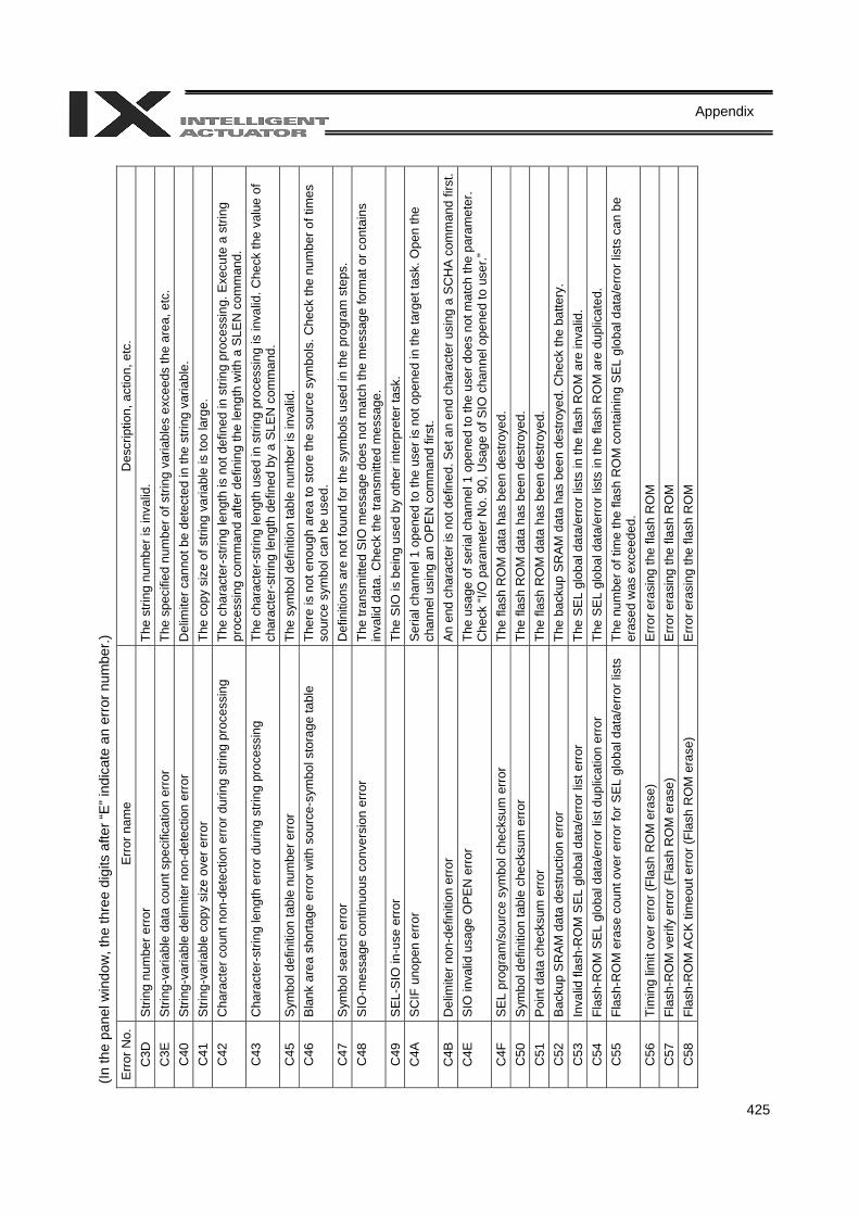
425
Appendix
(In th
e pa
nel w
indo
w, t
he th
ree
digi
ts a
fter “
E” in
dica
te a
n er
ror n
umbe
r.)
Err
or N
o.
Err
or n
ame
Des
crip
tion,
act
ion,
etc
. C
3D
Stri
ng n
umbe
r erro
r Th
e st
ring
num
ber i
s in
valid
. C
3E
Stri
ng-v
aria
ble
data
cou
nt s
peci
ficat
ion
erro
r Th
e sp
ecifi
ed n
umbe
r of s
tring
var
iabl
es e
xcee
ds th
e ar
ea, e
tc.
C40
S
tring
-var
iabl
e de
limite
r non
-det
ectio
n er
ror
Del
imite
r can
not b
e de
tect
ed in
the
strin
g va
riabl
e.
C41
S
tring
-var
iabl
e co
py s
ize
over
erro
r Th
e co
py s
ize
of s
tring
var
iabl
e is
too
larg
e.
C42
C
hara
cter
cou
nt n
on-d
etec
tion
erro
r dur
ing
strin
g pr
oces
sing
Th
e ch
arac
ter-
strin
g le
ngth
is n
ot d
efin
ed in
stri
ng p
roce
ssin
g. E
xecu
te a
stri
ng
proc
essi
ng c
omm
and
afte
r def
inin
g th
e le
ngth
with
a S
LEN
com
man
d.
C43
C
hara
cter
-stri
ng le
ngth
err
or d
urin
g st
ring
proc
essi
ng
The
char
acte
r-st
ring
leng
th u
sed
in s
tring
pro
cess
ing
is in
valid
. Che
ck th
e va
lue
of
char
acte
r-st
ring
leng
th d
efin
ed b
y a
SLE
N c
omm
and.
C
45
Sym
bol d
efin
ition
tabl
e nu
mbe
r err
or
The
sym
bol d
efin
ition
tabl
e nu
mbe
r is
inva
lid.
C46
B
lank
are
a sh
orta
ge e
rror
with
sou
rce-
sym
bol s
tora
ge ta
ble
Ther
e is
not
eno
ugh
area
to s
tore
the
sour
ce s
ymbo
ls. C
heck
the
num
ber o
f tim
es
sour
ce s
ymbo
l can
be
used
. C
47
Sym
bol s
earc
h er
ror
Def
initi
ons
are
not f
ound
for t
he s
ymbo
ls u
sed
in th
e pr
ogra
m s
teps
. C
48
SIO
-mes
sage
con
tinuo
us c
onve
rsio
n er
ror
The
trans
mitt
ed S
IO m
essa
ge d
oes
not m
atch
the
mes
sage
form
at o
r con
tain
s in
valid
dat
a. C
heck
the
trans
mitt
ed m
essa
ge.
C49
S
EL-S
IO in
-use
err
or
The
SIO
is b
eing
use
d by
oth
er in
terp
rete
r tas
k.
C4A
S
CIF
uno
pen
erro
r S
eria
l cha
nnel
1 o
pene
d to
the
user
is n
ot o
pene
d in
the
targ
et ta
sk. O
pen
the
chan
nel u
sing
an
OP
EN
com
man
d fir
st.
C4B
D
elim
iter n
on-d
efin
ition
erro
r A
n en
d ch
arac
ter i
s no
t def
ined
. Set
an
end
char
acte
r usi
ng a
SC
HA
com
man
d fir
st.
C4E
S
IO in
valid
usa
ge O
PE
N e
rror
Th
e us
age
of s
eria
l cha
nnel
1 o
pene
d to
the
user
doe
s no
t mat
ch th
e pa
ram
eter
. C
heck
“I/O
par
amet
er N
o. 9
0, U
sage
of S
IO c
hann
el o
pene
d to
use
r.”
C4F
S
EL p
rogr
am/s
ourc
e sy
mbo
l che
cksu
m e
rror
Th
e fla
sh R
OM
dat
a ha
s be
en d
estro
yed.
C
50
Sym
bol d
efin
ition
tabl
e ch
ecks
um e
rror
The
flash
RO
M d
ata
has
been
des
troye
d.
C51
P
oint
dat
a ch
ecks
um e
rror
Th
e fla
sh R
OM
dat
a ha
s be
en d
estro
yed.
C
52
Bac
kup
SR
AM
dat
a de
stru
ctio
n er
ror
The
back
up S
RA
M d
ata
has
been
des
troye
d. C
heck
the
batte
ry.
C53
In
valid
flas
h-R
OM
SEL
glo
bal d
ata/
erro
r lis
t erro
r Th
e S
EL
glob
al d
ata/
erro
r lis
ts in
the
flash
RO
M a
re in
valid
. C
54
Flas
h-R
OM
SE
L gl
obal
dat
a/er
ror l
ist d
uplic
atio
n er
ror
The
SE
L gl
obal
dat
a/er
ror l
ists
in th
e fla
sh R
OM
are
dup
licat
ed.
C55
Fl
ash-
RO
M e
rase
cou
nt o
ver e
rror
for S
EL g
loba
l dat
a/er
ror l
ists
Th
e nu
mbe
r of t
ime
the
flash
RO
M c
onta
inin
g S
EL g
loba
l dat
a/er
ror l
ists
can
be
eras
ed w
as e
xcee
ded.
C
56
Tim
ing
limit
over
erro
r (Fl
ash
RO
M e
rase
) E
rror e
rasi
ng th
e fla
sh R
OM
C
57
Flas
h-R
OM
ver
ify e
rror (
Flas
h R
OM
era
se)
Err
or e
rasi
ng th
e fla
sh R
OM
C
58
Flas
h-R
OM
AC
K ti
meo
ut e
rror (
Flas
h R
OM
era
se)
Err
or e
rasi
ng th
e fla
sh R
OM
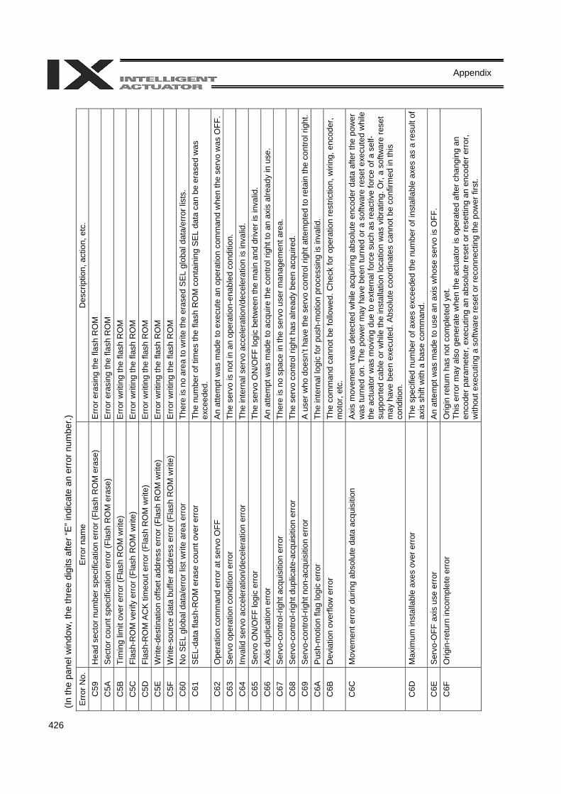
426
Appendix
(In th
e pa
nel w
indo
w, t
he th
ree
digi
ts a
fter “
E” in
dica
te a
n er
ror n
umbe
r.)
Err
or N
o.
Err
or n
ame
Des
crip
tion,
act
ion,
etc
. C
59
Hea
d se
ctor
num
ber s
peci
ficat
ion
erro
r (Fl
ash
RO
M e
rase
) E
rror
era
sing
the
flash
RO
M
C5A
S
ecto
r cou
nt s
peci
ficat
ion
erro
r (Fl
ash
RO
M e
rase
) E
rror
era
sing
the
flash
RO
M
C5B
Ti
min
g lim
it ov
er e
rror (
Flas
h R
OM
writ
e)
Erro
r writ
ing
the
flash
RO
M
C5C
Fl
ash-
RO
M v
erify
err
or (F
lash
RO
M w
rite)
Er
ror w
ritin
g th
e fla
sh R
OM
C
5D
Flas
h-R
OM
AC
K ti
meo
ut e
rror
(Fla
sh R
OM
writ
e)
Erro
r writ
ing
the
flash
RO
M
C5E
W
rite-
dest
inat
ion
offs
et a
ddre
ss e
rror
(Fla
sh R
OM
writ
e)
Erro
r writ
ing
the
flash
RO
M
C5F
W
rite-
sour
ce d
ata
buffe
r add
ress
err
or (F
lash
RO
M w
rite)
E
rror
writ
ing
the
flash
RO
M
C60
N
o S
EL
glob
al d
ata/
erro
r lis
t writ
e ar
ea e
rror
Th
ere
is n
o ar
ea to
writ
e th
e er
ased
SE
L gl
obal
dat
a/er
ror l
ists
. C
61
SEL
-dat
a fla
sh-R
OM
era
se c
ount
ove
r err
or
The
num
ber o
f tim
es th
e fla
sh R
OM
con
tain
ing
SEL
dat
a ca
n be
era
sed
was
ex
ceed
ed.
C62
O
pera
tion
com
man
d er
ror a
t ser
vo O
FF
An
atte
mpt
was
mad
e to
exe
cute
an
oper
atio
n co
mm
and
whe
n th
e se
rvo
was
OFF
. C
63
Ser
vo o
pera
tion
cond
ition
erro
r Th
e se
rvo
is n
ot in
an
oper
atio
n-en
able
d co
nditi
on.
C64
In
valid
ser
vo a
ccel
erat
ion/
dece
lera
tion
erro
r Th
e in
tern
al s
ervo
acc
eler
atio
n/de
cele
ratio
n is
inva
lid.
C65
S
ervo
ON
/OFF
logi
c er
ror
The
serv
o O
N/O
FF lo
gic
betw
een
the
mai
n an
d dr
iver
is in
valid
. C
66
Axi
s du
plic
atio
n er
ror
An a
ttem
pt w
as m
ade
to a
cqui
re th
e co
ntro
l rig
ht to
an
axis
alre
ady
in u
se.
C67
S
ervo
-con
trol-r
ight
acq
uisi
tion
erro
r Th
ere
is n
o sp
ace
in th
e se
rvo
user
man
agem
ent a
rea.
C
68
Ser
vo-c
ontro
l-rig
ht d
uplic
ate-
acqu
isiti
on e
rror
Th
e se
rvo
cont
rol r
ight
has
alre
ady
been
acq
uire
d.
C69
S
ervo
-con
trol-r
ight
non
-acq
uisi
tion
erro
r A
user
who
doe
sn’t
have
the
serv
o co
ntro
l rig
ht a
ttem
pted
to re
tain
the
cont
rol r
ight
. C
6A
Pus
h-m
otio
n fla
g lo
gic
erro
r Th
e in
tern
al lo
gic
for p
ush-
mot
ion
proc
essi
ng is
inva
lid.
C6B
D
evia
tion
over
flow
err
or
The
com
man
d ca
nnot
be
follo
wed
. Che
ck fo
r ope
ratio
n re
stric
tion,
wiri
ng, e
ncod
er,
mot
or, e
tc.
C6C
M
ovem
ent e
rror
dur
ing
abso
lute
dat
a ac
quis
ition
A
xis
mov
emen
t was
det
ecte
d w
hile
acq
uirin
g ab
solu
te e
ncod
er d
ata
afte
r the
pow
er
was
turn
ed o
n. T
he p
ower
may
hav
e be
en tu
rned
or a
sof
twar
e re
set e
xecu
ted
whi
le
the
actu
ator
was
mov
ing
due
to e
xter
nal f
orce
suc
h as
reac
tive
forc
e of
a s
elf-
supp
orte
d ca
ble
or w
hile
the
inst
alla
tion
loca
tion
was
vib
ratin
g. O
r, a
softw
are
rese
t m
ay h
ave
been
exe
cute
d. A
bsol
ute
coor
dina
tes
cann
ot b
e co
nfirm
ed in
this
co
nditi
on.
C6D
M
axim
um in
stal
labl
e ax
es o
ver e
rror
The
spec
ified
num
ber o
f axe
s ex
ceed
ed th
e nu
mbe
r of i
nsta
llabl
e ax
es a
s a
resu
lt of
ax
is s
hift
with
a b
ase
com
man
d.
C6E
S
ervo
-OFF
axi
s us
e er
ror
An
atte
mpt
was
mad
e to
use
an
axis
who
se s
ervo
is O
FF.
C6F
O
rigin
-ret
urn
inco
mpl
ete
erro
r O
rigin
retu
rn h
as n
ot c
ompl
eted
yet
. Th
is e
rror m
ay a
lso
gene
rate
whe
n th
e ac
tuat
or is
ope
rate
d af
ter c
hang
ing
an
enco
der p
aram
eter
, exe
cutin
g an
abs
olut
e re
set o
r res
ettin
g an
enc
oder
err
or,
with
out e
xecu
ting
a so
ftwar
e re
set o
r rec
onne
ctin
g th
e po
wer
firs
t.
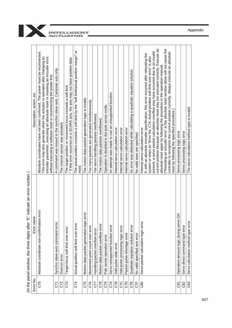
427
Appendix
(In th
e pa
nel w
indo
w, t
he th
ree
digi
ts a
fter “
E” in
dica
te a
n er
ror n
umbe
r.)
Err
or N
o.
Err
or n
ame
Des
crip
tion,
act
ion,
etc
. C
70
Abs
olut
e co
ordi
nate
non
-con
firm
atio
n er
ror
Abs
olut
e co
ordi
nate
s ha
ve n
ot b
een
conf
irmed
. The
pow
er m
ust b
e re
conn
ecte
d.
This
err
or m
ay a
lso
gene
rate
whe
n th
e ac
tuat
or is
ope
rate
d af
ter c
hang
ing
an
enco
der p
aram
eter
, exe
cutin
g an
abs
olut
e re
set o
r res
ettin
g an
enc
oder
err
or,
with
out e
xecu
ting
a so
ftwar
e re
set o
r rec
onne
ctin
g th
e po
wer
firs
t. C
71
Syn
chro
sla
ve-a
xis
com
man
d er
ror
A c
omm
and
was
issu
ed to
the
sync
hro
slav
e ax
is. C
arte
sian
axi
s on
ly.
C72
O
verr
un e
rror
Th
e ov
erru
n se
nsor
was
act
uate
d.
C73
Ta
rget
-locu
s so
ft lim
it ov
er e
rror
The
targ
et p
ositi
on o
r mov
emen
t loc
us e
xcee
ds a
sof
t lim
it.
* If
this
err
or o
ccur
red
on a
SC
AR
A a
xis,
the
axis
may
not
hav
e po
sitio
n da
ta.
C74
A
ctua
l-pos
ition
sof
t lim
it ov
er e
rror
Th
e ac
tual
pos
ition
exc
eeds
a s
oft l
imit
by th
e “s
oft l
imit/
actu
al p
ositi
on m
argi
n” o
r m
ore.
C
75
Mot
ion-
data
-pac
ket g
ener
atio
n lo
gic
erro
r Th
e m
otio
n-da
ta-p
acke
t gen
erat
ion
logi
c is
inva
lid.
C76
M
ovem
ent-p
oint
cou
nt o
ver e
rror
To
o m
any
pack
ets
are
gene
rate
d si
mul
tane
ousl
y.
C77
H
andl
ing-
pack
et o
verfl
ow e
rror
Th
e se
rvo
hand
ling
pack
ets
over
flow
ed.
C78
M
otio
n-da
ta-p
acke
t ove
rflow
err
or
The
mot
ion
data
pac
kets
ove
rflow
ed.
C79
P
ole
sens
e op
erat
ion
erro
r O
pera
tion
is d
isab
led
in th
e po
le s
ense
mod
e.
C7A
S
ervo
uns
uppo
rted
func
tion
erro
r A
n at
tem
pt w
as m
ade
to u
se a
n un
supp
orte
d fu
nctio
n.
C7B
O
dd-p
ulse
slid
e er
ror
Inte
rnal
ser
vo c
alcu
latio
n er
ror
C7C
O
dd-p
ulse
pro
cess
ing
logi
c er
ror
Inte
rnal
ser
vo c
alcu
latio
n er
ror
C7D
P
acke
t pul
se s
horta
ge e
rror
Inte
rnal
ser
vo c
alcu
latio
n er
ror
C7E
Q
uadr
atic
equ
atio
n so
lutio
n er
ror
An
erro
r was
det
ecte
d w
hile
cal
cula
ting
a qu
adra
tic e
quat
ion
solu
tion.
C
7F
No
valid
spe
cifie
d ax
is e
rror
No
valid
axe
s ar
e sp
ecifi
ed.
C80
S
ervo
-pac
ket c
alcu
latio
n lo
gic
erro
r In
tern
al s
ervo
cal
cula
tion
erro
r If,
with
an
abso
lute
enc
oder
spe
cific
atio
n, th
is e
rror
occ
urre
d af
ter r
eloc
atin
g th
e sy
stem
or w
hen
an “E
rror
No.
C74
, Act
ual-p
ositi
on s
oft l
imit
over
err
or” i
s al
so
pres
ent,
a se
rvo
pack
et c
alcu
latio
n ov
erflo
w m
ay h
ave
occu
rred
due
to a
n in
valid
cu
rren
t pos
ition
bec
ause
an
abso
lute
rese
t was
not
exe
cute
d co
rrec
tly. E
xecu
te a
n ab
solu
te re
set a
gain
by
follo
win
g th
e pr
oced
ure
in th
e op
erat
ion
man
ual.
(“R
eset
ting
an e
ncod
er e
rror
” in
the
abso
lute
rese
t win
dow
alo
ne w
ill no
t cau
se th
e co
ntro
ller t
o re
cogn
ize
the
curr
ent p
ositi
on c
orre
ctly
. Alw
ays
exec
ute
an a
bsol
ute
rese
t by
follo
win
g th
e sp
ecifi
ed p
roce
dure
.) C
81
Ope
ratio
n-am
ount
logi
c du
ring
serv
o O
N
Ser
vo p
roce
ssin
g lo
gic
erro
r C
82
Ser
vo d
irect
com
man
d ty
pe e
rror
Ser
vo p
roce
ssin
g lo
gic
erro
r C
83
Ser
vo c
alcu
latio
n m
etho
d ty
pe e
rror
The
serv
o ca
lcul
atio
n m
etho
d ty
pe is
inva
lid.
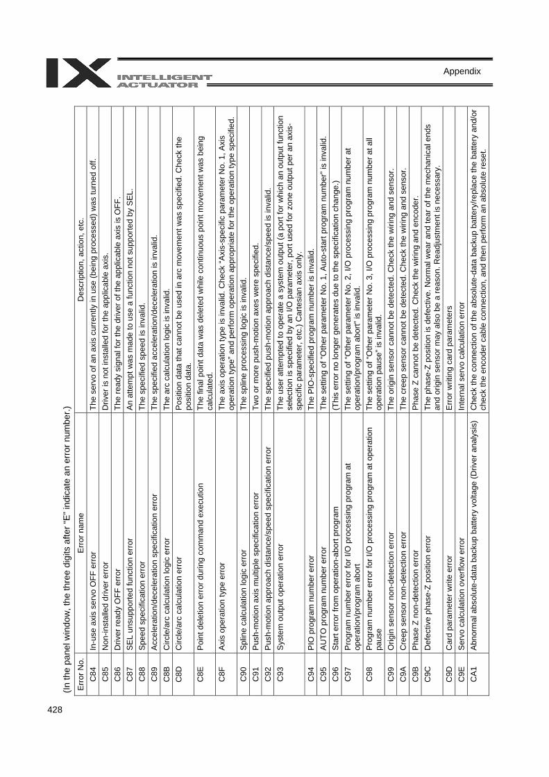
428
Appendix
(In th
e pa
nel w
indo
w, t
he th
ree
digi
ts a
fter “
E” in
dica
te a
n er
ror n
umbe
r.)
Err
or N
o.
Err
or n
ame
Des
crip
tion,
act
ion,
etc
. C
84
In-u
se a
xis
serv
o O
FF e
rror
Th
e se
rvo
of a
n ax
is c
urre
ntly
in u
se (b
eing
pro
cess
ed) w
as tu
rned
off.
C
85
Non
-inst
alle
d dr
iver
err
or
Driv
er is
not
inst
alle
d fo
r the
app
licab
le a
xis.
C
86
Driv
er re
ady
OFF
err
or
The
read
y si
gnal
for t
he d
river
of t
he a
pplic
able
axi
s is
OFF
. C
87
SEL
uns
uppo
rted
func
tion
erro
r A
n at
tem
pt w
as m
ade
to u
se a
func
tion
not s
uppo
rted
by S
EL.
C88
S
peed
spe
cific
atio
n er
ror
The
spec
ified
spe
ed is
inva
lid.
C89
A
ccel
erat
ion/
dece
lera
tion
spec
ifica
tion
erro
r Th
e sp
ecifi
ed a
ccel
erat
ion/
dece
lera
tion
is in
valid
. C
8B
Circ
le/a
rc c
alcu
latio
n lo
gic
erro
r Th
e ar
c ca
lcul
atio
n lo
gic
is in
valid
. C
8D
Circ
le/a
rc c
alcu
latio
n er
ror
Pos
ition
dat
a th
at c
anno
t be
used
in a
rc m
ovem
ent w
as s
peci
fied.
Che
ck th
e po
sitio
n da
ta.
C8E
P
oint
del
etio
n er
ror d
urin
g co
mm
and
exec
utio
n Th
e fin
al p
oint
dat
a w
as d
elet
ed w
hile
con
tinuo
us p
oint
mov
emen
t was
bei
ng
calc
ulat
ed.
C8F
A
xis
oper
atio
n ty
pe e
rror
The
axis
ope
ratio
n ty
pe is
inva
lid. C
heck
“Axi
s-sp
ecifi
c pa
ram
eter
No.
1, A
xis
oper
atio
n ty
pe” a
nd p
erfo
rm o
pera
tion
appr
opria
te fo
r the
ope
ratio
n ty
pe s
peci
fied.
C
90
Spl
ine
calc
ulat
ion
logi
c er
ror
The
splin
e pr
oces
sing
logi
c is
inva
lid.
C91
P
ush-
mot
ion
axis
mul
tiple
spe
cific
atio
n er
ror
Two
or m
ore
push
-mot
ion
axes
wer
e sp
ecifi
ed.
C92
P
ush-
mot
ion
appr
oach
dis
tanc
e/sp
eed
spec
ifica
tion
erro
r Th
e sp
ecifi
ed p
ush-
mot
ion
appr
oach
dis
tanc
e/sp
eed
is in
valid
. C
93
Sys
tem
out
put o
pera
tion
erro
r Th
e us
er a
ttem
pted
to o
pera
te a
sys
tem
out
put (
a po
rt fo
r whi
ch a
n ou
tput
func
tion
sele
ctio
n is
spe
cifie
d by
an
I/O p
aram
eter
, por
t use
d fo
r zon
e ou
tput
per
an
axis
-sp
ecifi
c pa
ram
eter
, etc
.) C
arte
sian
axi
s on
ly.
C94
P
IO p
rogr
am n
umbe
r err
or
The
PIO
-spe
cifie
d pr
ogra
m n
umbe
r is
inva
lid.
C95
A
UTO
pro
gram
num
ber e
rror
Th
e se
tting
of “
Oth
er p
aram
eter
No.
1, A
uto-
star
t pro
gram
num
ber”
is in
valid
. C
96
Sta
rt er
ror f
rom
ope
ratio
n-ab
ort p
rogr
am
(Thi
s er
ror n
o lo
nger
gen
erat
es d
ue to
the
spec
ifica
tion
chan
ge.)
C97
P
rogr
am n
umbe
r err
or fo
r I/O
pro
cess
ing
prog
ram
at
oper
atio
n/pr
ogra
m a
bort
The
setti
ng o
f “O
ther
par
amet
er N
o. 2
, I/O
pro
cess
ing
prog
ram
num
ber a
t op
erat
ion/
prog
ram
abo
rt” is
inva
lid.
C98
P
rogr
am n
umbe
r err
or fo
r I/O
pro
cess
ing
prog
ram
at o
pera
tion
paus
e Th
e se
tting
of “
Oth
er p
aram
eter
No.
3, I
/O p
roce
ssin
g pr
ogra
m n
umbe
r at a
ll op
erat
ion
paus
e” is
inva
lid.
C99
O
rigin
sen
sor n
on-d
etec
tion
erro
r Th
e or
igin
sen
sor c
anno
t be
dete
cted
. Che
ck th
e w
iring
and
sen
sor.
C9A
C
reep
sen
sor n
on-d
etec
tion
erro
r Th
e cr
eep
sens
or c
anno
t be
dete
cted
. Che
ck th
e w
iring
and
sen
sor.
C9B
P
hase
Z n
on-d
etec
tion
erro
r P
hase
Z c
anno
t be
dete
cted
. Che
ck th
e w
iring
and
enc
oder
. C
9C
Def
ectiv
e ph
ase-
Z po
sitio
n er
ror
The
phas
e-Z
posi
tion
is d
efec
tive.
Nor
mal
wea
r and
tear
of t
he m
echa
nica
l end
s an
d or
igin
sen
sor m
ay a
lso
be a
reas
on. R
eadj
ustm
ent i
s ne
cess
ary.
C
9D
Car
d pa
ram
eter
writ
e er
ror
Err
or w
ritin
g ca
rd p
aram
eter
s C
9E
Ser
vo c
alcu
latio
n ov
erflo
w e
rror
In
tern
al s
ervo
cal
cula
tion
erro
r C
A1
Abn
orm
al a
bsol
ute-
data
bac
kup
batte
ry v
olta
ge (D
river
ana
lysi
s)
Che
ck th
e co
nnec
tion
of th
e ab
solu
te-d
ata
back
up b
atte
ry/re
plac
e th
e ba
ttery
and
/or
chec
k th
e en
code
r cab
le c
onne
ctio
n, a
nd th
en p
erfo
rm a
n ab
solu
te re
set.
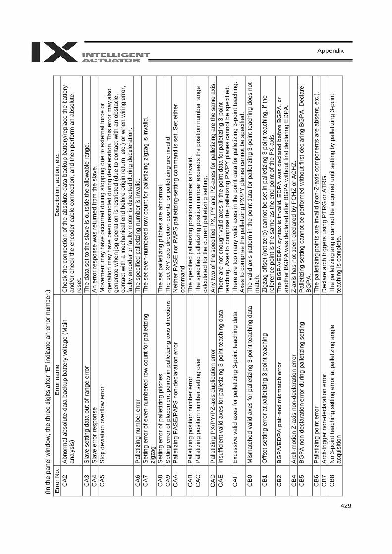
429
Appendix
(In th
e pa
nel w
indo
w, t
he th
ree
digi
ts a
fter “
E” in
dica
te a
n er
ror n
umbe
r.)
Err
or N
o.E
rror
nam
e D
escr
iptio
n, a
ctio
n, e
tc.
CA
2 A
bnor
mal
abs
olut
e-da
ta b
acku
p ba
ttery
vol
tage
(Mai
n an
alys
is)
Che
ck th
e co
nnec
tion
of th
e ab
solu
te-d
ata
back
up b
atte
ry/re
plac
e th
e ba
ttery
an
d/or
che
ck th
e en
code
r cab
le c
onne
ctio
n, a
nd th
en p
erfo
rm a
n ab
solu
te
rese
t. C
A3
Sla
ve s
ettin
g da
ta o
ut-o
f-ran
ge e
rror
The
data
set
to th
e sl
ave
is o
utsi
de th
e al
low
able
rang
e.
CA
4 S
lave
erro
r res
pons
e A
n er
ror r
espo
nse
was
retu
rned
from
the
slav
e.
CA
5 S
top
devi
atio
n ov
erflo
w e
rror
M
ovem
ent m
ay h
ave
occu
rred
dur
ing
stop
ping
due
to e
xter
nal f
orce
or
oper
atio
n m
ay h
ave
been
rest
ricte
d du
ring
dece
lera
tion.
Thi
s er
ror m
ay a
lso
gene
rate
whe
n jo
g op
erat
ion
is re
stric
ted
(due
to c
onta
ct w
ith a
n ob
stac
le,
cont
act w
ith a
mec
hani
cal e
nd b
efor
e or
igin
retu
rn, e
tc.)
or w
hen
wiri
ng e
rror,
faul
ty e
ncod
er o
r fau
lty m
otor
is d
etec
ted
durin
g de
cele
ratio
n.
CA
6 P
alle
tizin
g nu
mbe
r erro
r Th
e sp
ecifi
ed p
alle
tizin
g nu
mbe
r is
inva
lid.
CA
7 S
ettin
g er
ror o
f eve
n-nu
mbe
red
row
cou
nt fo
r pal
letiz
ing
zigz
ag
The
set e
ven-
num
bere
d ro
w c
ount
for p
alle
tizin
g zi
gzag
is in
valid
.
CA
8 S
ettin
g er
ror o
f pal
letiz
ing
pitc
hes
The
set p
alle
tizin
g pi
tche
s ar
e ab
norm
al.
CA
9 S
ettin
g er
ror o
f pla
cem
ent p
oint
s in
pal
letiz
ing-
axis
dire
ctio
ns
The
set X
/Y-a
xis
dire
ctio
n co
unts
for p
alle
tizin
g ar
e in
valid
. C
AA
P
alle
tizin
g P
AS
E/P
AP
S n
on-d
ecla
ratio
n er
ror
Nei
ther
PA
SE
nor
PA
PS
pal
letiz
ing-
setti
ng c
omm
and
is s
et. S
et e
ither
co
mm
and.
C
AB
P
alle
tizin
g po
sitio
n nu
mbe
r erro
r Th
e sp
ecifi
ed p
alle
tizin
g po
sitio
n nu
mbe
r is
inva
lid.
CA
C
Pal
letiz
ing
posi
tion
num
ber s
ettin
g ov
er
The
spec
ified
pal
letiz
ing
posi
tion
num
ber e
xcee
ds th
e po
sitio
n nu
mbe
r ran
ge
calc
ulat
ed fo
r the
cur
rent
pal
letiz
ing
setti
ng.
CA
D
Pal
letiz
ing
PX
/PY
/PZ-
axis
dup
licat
ion
erro
r A
ny tw
o of
the
spec
ified
PX
, PY
and
PZ-
axes
for p
alle
tizin
g ar
e th
e sa
me
axis
. C
AE
In
suffi
cien
t val
id a
xes
for p
alle
tizin
g 3-
poin
t tea
chin
g da
ta
Ther
e ar
e no
t eno
ugh
valid
axe
s in
the
poin
t dat
a fo
r pal
letiz
ing
3-po
int
teac
hing
. Axe
s to
com
pris
e th
e pa
lletiz
ing
PX
/PY
pla
nes
cann
ot b
e sp
ecifi
ed.
CA
F E
xces
sive
val
id a
xes
for p
alle
tizin
g 3-
poin
t tea
chin
g da
ta
Ther
e ar
e to
o m
any
valid
axe
s in
the
poin
t dat
a fo
r pal
letiz
ing
3-po
int t
each
ing.
A
xes
to c
ompr
ise
the
palle
tizin
g P
X/P
Y p
lane
s ca
nnot
be
spec
ified
. C
B0
Mis
mat
ched
val
id a
xes
for p
alle
tizin
g 3-
poin
t tea
chin
g da
ta
The
valid
axi
s pa
ttern
in th
e po
int d
ata
for p
alle
tizin
g 3-
poin
t tea
chin
g do
es n
ot
mat
ch.
CB
1 O
ffset
set
ting
erro
r at p
alle
tizin
g 3-
poin
t tea
chin
g Zi
gzag
offs
et (n
ot z
ero)
can
not b
e se
t in
palle
tizin
g 3-
poin
t tea
chin
g, if
the
refe
renc
e po
int i
s th
e sa
me
as th
e en
d po
int o
f the
PX
-axi
s.
CB
2 B
GP
A/E
DPA
pai
r-end
mis
mat
ch e
rror
Th
e B
GP
A/E
DP
A s
ynta
x is
inva
lid. E
DP
A w
as d
ecla
red
befo
re B
GP
A, o
r an
othe
r BG
PA
was
dec
lare
d af
ter B
GP
A w
ithou
t firs
t dec
larin
g E
DP
A.
CB
4 A
rch-
mot
ion
Z-ax
is n
on-d
ecla
ratio
n er
ror
Z-ax
is h
as n
ot b
een
decl
ared
by
PC
HZ
or A
CH
Z.
CB
5 B
GP
A n
on-d
ecla
ratio
n er
ror d
urin
g pa
lletiz
ing
setti
ng
Pal
letiz
ing
setti
ng c
anno
t be
perfo
rmed
with
out f
irst d
ecla
ring
BG
PA
. Dec
lare
B
GP
A.
CB
6 P
alle
tizin
g po
int e
rror
Th
e pa
lletiz
ing
poin
ts a
re in
valid
(non
-Z-a
xis
com
pone
nts
are
abse
nt, e
tc.).
C
B7
Arc
h-tri
gger
non
-dec
lara
tion
erro
r D
ecla
re a
rch
trigg
ers
usin
g P
TRG
or A
TRG
. C
B8
No
3-po
int t
each
ing
setti
ng e
rror a
t pal
letiz
ing
angl
e ac
quis
ition
Th
e pa
lletiz
ing
angl
e ca
nnot
be
acqu
ired
until
set
ting
by p
alle
tizin
g 3-
poin
t te
achi
ng is
com
plet
e.
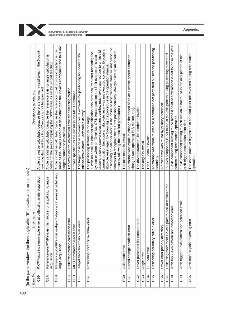
430
Appendix
(In th
e pa
nel w
indo
w, t
he th
ree
digi
ts a
fter “
E” in
dica
te a
n er
ror n
umbe
r.)
Err
or N
o.
Err
or n
ame
Des
crip
tion,
act
ion,
etc
. C
B9
PX/
PY-
axis
inde
term
inab
le e
rror
at p
alle
tizin
g an
gle
acqu
isiti
on
Ang
le c
anno
t be
calc
ulat
ed b
ecau
se th
ere
are
too
man
y va
lid a
xes
in th
e 3-
poin
t te
achi
ng d
ata
and
thus
PX
/PY-
axes
can
not b
e sp
ecifi
ed.
CB
A
Ref
eren
ce-a
xis/
PY/
PY-
axis
mis
mat
ch e
rror
at p
alle
tizin
g an
gle
acqu
isiti
on
Ang
le c
anno
t be
calc
ulat
ed b
ecau
se th
e re
fere
nce
axis
for a
ngle
cal
cula
tion
is
neith
er o
f the
axe
s co
mpr
isin
g th
e P
X/P
Y-a
xes
as s
et b
y 3-
poin
t tea
chin
g.
CB
B
Ref
eren
ce-p
oint
/PX
-axi
s en
d-po
int d
uplic
atio
n er
ror a
t pal
letiz
ing
angl
e ac
quis
ition
A
ngle
can
not b
e ca
lcul
ated
bec
ause
the
refe
renc
e po
int o
f 3-p
oint
teac
hing
is th
e sa
me
as th
e P
X-a
xis
end-
poin
t dat
a ot
her t
han
the
PZ-
axis
com
pone
nt a
nd th
us a
rc
tang
ent c
anno
t be
calc
ulat
ed.
CB
C
Pal
letiz
ing
mot
ion
calc
ulat
ion
erro
r Tr
apez
oid
cont
rol c
alcu
latio
n er
ror f
or p
alle
tizin
g m
otio
n C
BD
M
OD
com
man
d di
viso
r 0 e
rror
“0” w
as s
peci
fied
as th
e di
viso
r in
the
MO
D c
omm
and.
C
BE
Ta
rget
trac
k bo
unda
ry o
ver e
rror
Th
e ta
rget
pos
ition
or m
ovem
ent l
ocus
exc
eeds
the
posi
tioni
ng b
ound
ary
in th
e in
finite
-stro
ke m
ode.
Car
tesi
an a
xis
only
. C
BF
Pos
ition
ing
dist
ance
ove
rflow
erro
r Th
e po
sitio
ning
dis
tanc
e is
too
larg
e.
If, w
ith a
n ab
solu
te e
ncod
er s
peci
ficat
ion,
this
err
or o
ccur
red
afte
r rel
ocat
ing
the
syst
em o
r whe
n an
“Err
or N
o. C
74, A
ctua
l-pos
ition
sof
t lim
it ov
er e
rror
” is
also
pr
esen
t, a
serv
o pa
cket
cal
cula
tion
over
flow
may
hav
e oc
curre
d du
e to
an
inva
lid
curr
ent p
ositi
on b
ecau
se a
n ab
solu
te re
set w
as n
ot e
xecu
ted
corr
ectly
. Exe
cute
an
abso
lute
rese
t aga
in b
y fo
llow
ing
the
proc
edur
e in
the
oper
atio
n m
anua
l. (“
Res
ettin
g an
enc
oder
err
or” i
n th
e ab
solu
te re
set w
indo
w a
lone
will
not c
ause
the
cont
rolle
r to
reco
gniz
e th
e cu
rren
t pos
ition
cor
rect
ly. A
lway
s ex
ecut
e an
abs
olut
e re
set b
y fo
llow
ing
the
spec
ified
pro
cedu
re.)
CC
0 A
xis
mod
e er
ror
The
axis
mod
e is
inva
lid.
CC
1 S
peed
cha
nge
cond
ition
err
or
An
atte
mpt
was
mad
e to
cha
nge
the
spee
d of
an
axis
who
se s
peed
can
not b
e ch
ange
d (a
xis
oper
atin
g in
S-m
otio
n, e
tc.).
C
C2
Driv
er p
aram
eter
list
num
ber e
rror
The
driv
er p
aram
eter
list
num
ber i
s in
valid
. C
C3
Ang
le e
rror
The
angl
e is
inva
lid.
CC
4 S
EL d
ata
erro
r Th
e S
EL
data
is in
valid
. C
C5
Pos
ition
ing
boun
dary
pul
l-out
erro
r A
n at
tem
pt w
as m
ade
to e
xecu
te a
com
man
d no
t per
mitt
ed o
utsi
de th
e po
sitio
ning
bo
unda
ry.
CC
6 D
river
erro
r prim
ary
dete
ctio
n A
driv
er e
rror w
as fo
und
by p
rimar
y de
tect
ion.
C
C7
Pal
letiz
ing
mov
emen
t PZ-
axis
pat
tern
non
-det
ectio
n er
ror
PZ-
axis
com
pone
nt is
not
foun
d in
the
axis
pat
tern
dur
ing
palle
tizin
g m
ovem
ent.
CC
8 A
rch
top
Z-ax
is p
atte
rn n
on-d
etec
tion
erro
r Z-
axis
com
pone
nt re
latin
g to
the
high
est p
oint
of a
rch
mot
ion
is n
ot fo
und
in th
e ax
is
patte
rn d
urin
g ar
ch m
otio
n op
erat
ion.
C
C9
Arc
h tri
gger
Z-a
xis
patte
rn n
on-d
etec
tion
erro
r Z-
axis
com
pone
nt re
latin
g to
arc
h m
otio
n is
not
foun
d in
the
axis
pat
tern
of t
he
arch
-trig
ger d
ecla
ratio
n po
int d
ata.
C
CA
A
rch
top/
end-
poin
t rev
ersi
ng e
rror
Th
e co
ordi
nate
s of
hig
hest
poi
nt a
nd e
nd p
oint
are
reve
rsed
dur
ing
arch
mot
ion
oper
atio
n.
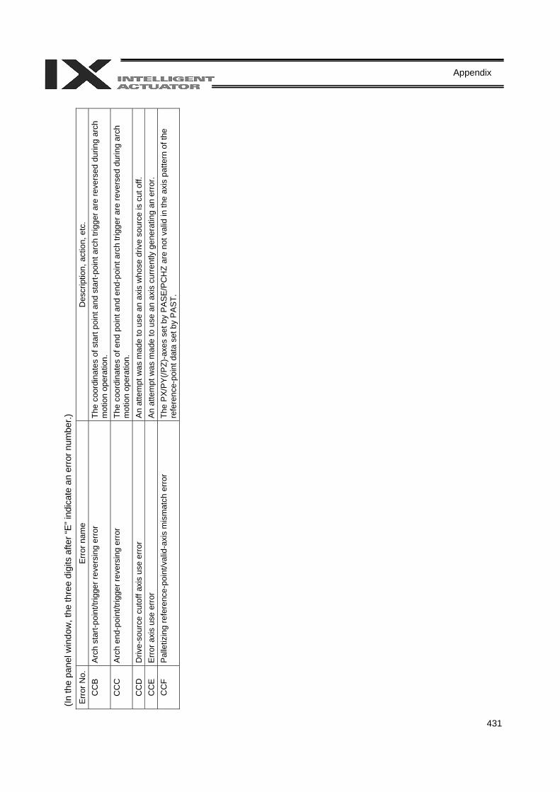
431
Appendix
(In th
e pa
nel w
indo
w, t
he th
ree
digi
ts a
fter “
E” in
dica
te a
n er
ror n
umbe
r.)
Err
or N
o.
Err
or n
ame
Des
crip
tion,
act
ion,
etc
. C
CB
Arc
h st
art-p
oint
/trig
ger r
ever
sing
erro
r Th
e co
ordi
nate
s of
sta
rt po
int a
nd s
tart-
poin
t arc
h tri
gger
are
reve
rsed
dur
ing
arch
m
otio
n op
erat
ion.
C
CC
A
rch
end-
poin
t/trig
ger r
ever
sing
erro
r Th
e co
ordi
nate
s of
end
poi
nt a
nd e
nd-p
oint
arc
h tri
gger
are
reve
rsed
dur
ing
arch
m
otio
n op
erat
ion.
C
CD
D
rive-
sour
ce c
utof
f axi
s us
e er
ror
An
atte
mpt
was
mad
e to
use
an
axis
who
se d
rive
sour
ce is
cut
off.
C
CE
Erro
r axi
s us
e er
ror
An a
ttem
pt w
as m
ade
to u
se a
n ax
is c
urre
ntly
gen
erat
ing
an e
rror
. C
CF
Pal
letiz
ing
refe
renc
e-po
int/v
alid
-axi
s m
ism
atch
err
or
The
PX
/PY(
/PZ)
-axe
s se
t by
PA
SE
/PC
HZ
are
not v
alid
in th
e ax
is p
atte
rn o
f the
re
fere
nce-
poin
t dat
a se
t by
PAST
.
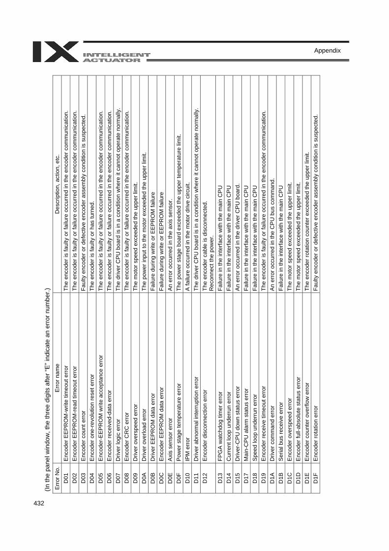
432
Appendix
(In th
e pa
nel w
indo
w, t
he th
ree
digi
ts a
fter “
E” in
dica
te a
n er
ror n
umbe
r.)
Err
or N
o.
Err
or n
ame
Des
crip
tion,
act
ion,
etc
. D
01
Enc
oder
EE
PR
OM
-writ
e tim
eout
erro
r Th
e en
code
r is
faul
ty o
r fai
lure
occ
urre
d in
the
enco
der c
omm
unic
atio
n.
D02
E
ncod
er E
EP
RO
M-r
ead
timeo
ut e
rror
Th
e en
code
r is
faul
ty o
r fai
lure
occ
urre
d in
the
enco
der c
omm
unic
atio
n.
D03
E
ncod
er c
ount
err
or
Faul
ty e
ncod
er o
r def
ectiv
e en
code
r ass
embl
y co
nditi
on is
sus
pect
ed.
D04
E
ncod
er o
ne-re
volu
tion
rese
t erro
r Th
e en
code
r is
faul
ty o
r has
turn
ed.
D05
E
ncod
er-E
EP
RO
M w
rite
acce
ptan
ce e
rror
Th
e en
code
r is
faul
ty o
r fai
lure
occ
urre
d in
the
enco
der c
omm
unic
atio
n.
D06
E
ncod
er re
ceiv
ed-d
ata
erro
r Th
e en
code
r is
faul
ty o
r fai
lure
occ
urre
d in
the
enco
der c
omm
unic
atio
n.
D07
D
river
logi
c er
ror
The
driv
er C
PU
boa
rd is
in a
con
ditio
n w
here
it c
anno
t ope
rate
nor
mal
ly.
D08
E
ncod
er C
RC
err
or
The
enco
der i
s fa
ulty
or f
ailu
re o
ccur
red
in th
e en
code
r com
mun
icat
ion.
D
09
Driv
er o
vers
peed
erro
r Th
e m
otor
spe
ed e
xcee
ded
the
uppe
r lim
it.
D0A
D
river
ove
rload
erro
r Th
e po
wer
inpu
t to
the
mot
or e
xcee
ded
the
uppe
r lim
it.
D0B
D
river
EE
PR
OM
dat
a er
ror
Failu
re d
urin
g w
rite
or E
EP
RO
M fa
ilure
D
0C
Enc
oder
EE
PR
OM
dat
a er
ror
Failu
re d
urin
g w
rite
or E
EP
RO
M fa
ilure
D
0E
Axi
s se
nsor
err
or
An
erro
r occ
urre
d in
the
axis
sen
sor.
D0F
P
ower
sta
ge te
mpe
ratu
re e
rror
The
pow
er s
tage
boa
rd e
xcee
ded
the
uppe
r tem
pera
ture
lim
it.
D10
IP
M e
rror
A fa
ilure
occ
urre
d in
the
mot
or d
rive
circ
uit.
D11
D
river
abn
orm
al in
terr
uptio
n er
ror
The
driv
er C
PU
boa
rd is
in a
con
ditio
n w
here
it c
anno
t ope
rate
nor
mal
ly.
D12
E
ncod
er d
isco
nnec
tion
erro
r Th
e en
code
r cab
le is
dis
conn
ecte
d.
Rec
onne
ct th
e po
wer
. D
13
FPG
A w
atch
dog
timer
erro
r Fa
ilure
in th
e in
terfa
ce w
ith th
e m
ain
CP
U
D14
C
urre
nt lo
op u
nder
run
erro
r Fa
ilure
in th
e in
terfa
ce w
ith th
e m
ain
CP
U
D15
D
river
-CP
U d
own
stat
us e
rror
A
n er
ror o
ccur
red
in th
e dr
iver
CP
U b
oard
. D
17
Mai
n-C
PU
ala
rm s
tatu
s er
ror
Failu
re in
the
inte
rface
with
the
mai
n C
PU
D
18
Spe
ed lo
op u
nder
run
erro
r Fa
ilure
in th
e in
terfa
ce w
ith th
e m
ain
CP
U
D19
E
ncod
er re
ceiv
e tim
eout
err
or
The
enco
der i
s fa
ulty
or f
ailu
re o
ccur
red
in th
e en
code
r com
mun
icat
ion.
D
1A
Driv
er c
omm
and
erro
r A
n er
ror o
ccur
red
in th
e C
PU
bus
com
man
d.
D1B
S
eria
l bus
rece
ive
erro
r Fa
ilure
in th
e in
terfa
ce w
ith th
e m
ain
CP
U
D1C
E
ncod
er o
vers
peed
erro
r Th
e m
otor
spe
ed e
xcee
ded
the
uppe
r lim
it.
D1D
E
ncod
er fu
ll-ab
solu
te s
tatu
s er
ror
The
mot
or s
peed
exc
eede
d th
e up
per l
imit.
D
1E
Enc
oder
cou
nter
ove
rflow
err
or
The
enco
der r
otat
ion
coun
ter e
xcee
ded
the
uppe
r lim
it.
D1F
E
ncod
er ro
tatio
n er
ror
Faul
ty e
ncod
er o
r def
ectiv
e en
code
r ass
embl
y co
nditi
on is
sus
pect
ed.
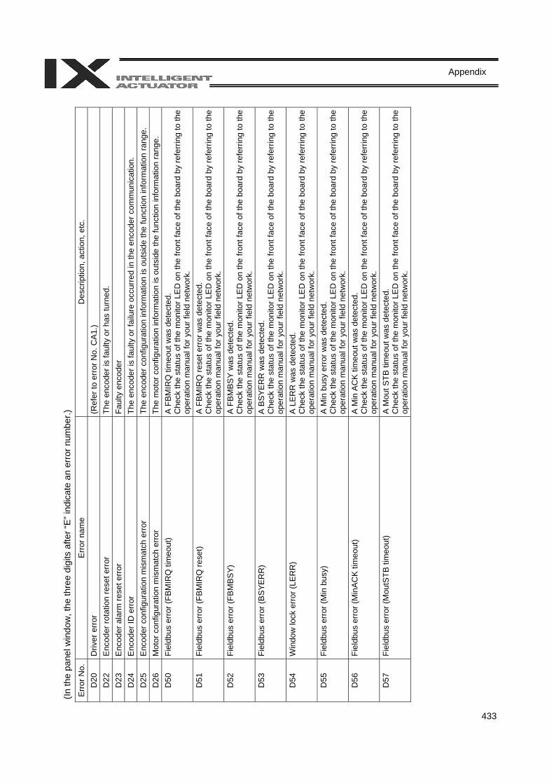
433
Appendix
(In th
e pa
nel w
indo
w, t
he th
ree
digi
ts a
fter “
E” in
dica
te a
n er
ror n
umbe
r.)
Err
or N
o.
Err
or n
ame
Des
crip
tion,
act
ion,
etc
. D
20
Driv
er e
rror
(R
efer
to e
rror
No.
CA
1.)
D22
E
ncod
er ro
tatio
n re
set e
rror
Th
e en
code
r is
faul
ty o
r has
turn
ed.
D23
E
ncod
er a
larm
rese
t err
or
Faul
ty e
ncod
er
D24
E
ncod
er ID
err
or
The
enco
der i
s fa
ulty
or f
ailu
re o
ccur
red
in th
e en
code
r com
mun
icat
ion.
D
25
Enc
oder
con
figur
atio
n m
ism
atch
err
or
The
enco
der c
onfig
urat
ion
info
rmat
ion
is o
utsi
de th
e fu
nctio
n in
form
atio
n ra
nge.
D
26
Mot
or c
onfig
urat
ion
mis
mat
ch e
rror
The
mot
or c
onfig
urat
ion
info
rmat
ion
is o
utsi
de th
e fu
nctio
n in
form
atio
n ra
nge.
D
50
Fiel
dbus
err
or (F
BM
IRQ
tim
eout
) A
FB
MIR
Q ti
meo
ut w
as d
etec
ted.
C
heck
the
stat
us o
f the
mon
itor L
ED
on
the
front
face
of t
he b
oard
by
refe
rrin
g to
the
oper
atio
n m
anua
l for
you
r fie
ld n
etw
ork.
D
51
Fiel
dbus
err
or (F
BM
IRQ
rese
t) A
FB
MIR
Q re
set e
rror
was
det
ecte
d.
Che
ck th
e st
atus
of t
he m
onito
r LE
D o
n th
e fro
nt fa
ce o
f the
boa
rd b
y re
ferr
ing
to th
e op
erat
ion
man
ual f
or y
our f
ield
net
wor
k.
D52
Fi
eldb
us e
rror
(FB
MB
SY)
A
FB
MB
SY
was
det
ecte
d.
Che
ck th
e st
atus
of t
he m
onito
r LE
D o
n th
e fro
nt fa
ce o
f the
boa
rd b
y re
ferr
ing
to th
e op
erat
ion
man
ual f
or y
our f
ield
net
wor
k.
D53
Fi
eldb
us e
rror (
BS
YER
R)
A B
SY
ER
R w
as d
etec
ted.
C
heck
the
stat
us o
f the
mon
itor L
ED
on
the
front
face
of t
he b
oard
by
refe
rrin
g to
the
oper
atio
n m
anua
l for
you
r fie
ld n
etw
ork.
D
54
Win
dow
lock
erro
r (LE
RR
) A
LE
RR
was
det
ecte
d.
Che
ck th
e st
atus
of t
he m
onito
r LE
D o
n th
e fro
nt fa
ce o
f the
boa
rd b
y re
ferr
ing
to th
e op
erat
ion
man
ual f
or y
our f
ield
net
wor
k.
D55
Fi
eldb
us e
rror
(Min
bus
y)
A M
in b
usy
erro
r was
det
ecte
d.
Che
ck th
e st
atus
of t
he m
onito
r LE
D o
n th
e fro
nt fa
ce o
f the
boa
rd b
y re
ferr
ing
to th
e op
erat
ion
man
ual f
or y
our f
ield
net
wor
k.
D56
Fi
eldb
us e
rror
(Min
AC
K ti
meo
ut)
A M
in A
CK
tim
eout
was
det
ecte
d.
Che
ck th
e st
atus
of t
he m
onito
r LE
D o
n th
e fro
nt fa
ce o
f the
boa
rd b
y re
ferr
ing
to th
e op
erat
ion
man
ual f
or y
our f
ield
net
wor
k.
D57
Fi
eldb
us e
rror
(Mou
tSTB
tim
eout
) A
Mou
t STB
tim
eout
was
det
ecte
d.
Che
ck th
e st
atus
of t
he m
onito
r LE
D o
n th
e fro
nt fa
ce o
f the
boa
rd b
y re
ferr
ing
to th
e op
erat
ion
man
ual f
or y
our f
ield
net
wor
k.
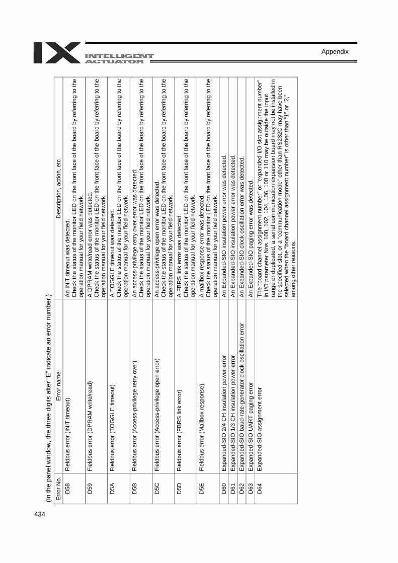
434
Appendix
(In th
e pa
nel w
indo
w, t
he th
ree
digi
ts a
fter “
E” in
dica
te a
n er
ror n
umbe
r.)
Err
or N
o.
Err
or n
ame
Des
crip
tion,
act
ion,
etc
. D
58
Fiel
dbus
err
or (I
NIT
tim
eout
) An
INIT
tim
eout
was
det
ecte
d.
Che
ck th
e st
atus
of t
he m
onito
r LE
D o
n th
e fro
nt fa
ce o
f the
boa
rd b
y re
ferr
ing
to th
e op
erat
ion
man
ual f
or y
our f
ield
net
wor
k.
D59
Fi
eldb
us e
rror
(DP
RA
M w
rite/
read
) A
DP
RA
M w
rite/
read
err
or w
as d
etec
ted.
C
heck
the
stat
us o
f the
mon
itor L
ED
on
the
front
face
of t
he b
oard
by
refe
rrin
g to
the
oper
atio
n m
anua
l for
you
r fie
ld n
etw
ork.
D
5A
Fiel
dbus
err
or (T
OG
GLE
tim
eout
) A
TO
GG
LE ti
meo
ut w
as d
etec
ted.
C
heck
the
stat
us o
f the
mon
itor L
ED
on
the
front
face
of t
he b
oard
by
refe
rrin
g to
the
oper
atio
n m
anua
l for
you
r fie
ld n
etw
ork.
D
5B
Fiel
dbus
err
or (A
cces
s-pr
ivile
ge re
try o
ver)
A
n ac
cess
-priv
ilege
retry
ove
r err
or w
as d
etec
ted.
C
heck
the
stat
us o
f the
mon
itor L
ED
on
the
front
face
of t
he b
oard
by
refe
rrin
g to
the
oper
atio
n m
anua
l for
you
r fie
ld n
etw
ork.
D
5C
Fiel
dbus
err
or (A
cces
s-pr
ivile
ge o
pen
erro
r)
An
acce
ss-p
rivile
ge o
pen
erro
r was
det
ecte
d.
Che
ck th
e st
atus
of t
he m
onito
r LE
D o
n th
e fro
nt fa
ce o
f the
boa
rd b
y re
ferr
ing
to th
e op
erat
ion
man
ual f
or y
our f
ield
net
wor
k.
D5D
Fi
eldb
us e
rror (
FBR
S li
nk e
rror)
A F
BR
S li
nk e
rror w
as d
etec
ted.
C
heck
the
stat
us o
f the
mon
itor L
ED
on
the
front
face
of t
he b
oard
by
refe
rrin
g to
the
oper
atio
n m
anua
l for
you
r fie
ld n
etw
ork.
D
5E
Fiel
dbus
err
or (M
ailb
ox re
spon
se)
A m
ailb
ox re
spon
se e
rror
was
det
ecte
d.
Che
ck th
e st
atus
of t
he m
onito
r LE
D o
n th
e fro
nt fa
ce o
f the
boa
rd b
y re
ferr
ing
to th
e op
erat
ion
man
ual f
or y
our f
ield
net
wor
k.
D60
E
xpan
ded-
SIO
2/4
CH
insu
latio
n po
wer
erro
r A
n E
xpan
ded-
SIO
insu
latio
n po
wer
err
or w
as d
etec
ted.
D
61
Exp
ande
d-S
IO 1
/3 C
H in
sula
tion
pow
er e
rror
A
n E
xpan
ded-
SIO
insu
latio
n po
wer
err
or w
as d
etec
ted.
D
62
Exp
ande
d-S
IO b
aud-
rate
-gen
erat
or c
lock
osc
illat
ion
erro
r A
n E
xpan
ded-
SIO
clo
ck o
scilla
tion
erro
r was
det
ecte
d.
D63
E
xpan
ded-
SIO
UA
RT
pagi
ng e
rror
An
Exp
ande
d-S
IO p
agin
g er
ror w
as d
etec
ted.
D
64
Exp
ande
d-S
IO a
ssig
nmen
t erro
r Th
e “b
oard
cha
nnel
ass
ignm
ent n
umbe
r” o
r “ex
pand
ed-I/
O s
lot a
ssig
nmen
t num
ber”
in
I/O
par
amet
er N
os. 1
00, 1
02, 1
04, 1
06, 1
08 o
r 110
may
be
outs
ide
the
inpu
t ra
nge
or d
uplic
ated
, a s
eria
l com
mun
icat
ion
expa
nsio
n bo
ard
may
not
be
inst
alle
d in
th
e sp
ecifi
ed s
lot,
or a
“com
mun
icat
ion
mod
e” o
ther
than
RS
232C
may
hav
e be
en
sele
cted
whe
n th
e “b
oard
cha
nnel
ass
ignm
ent n
umbe
r” is
oth
er th
an “1
” or “
2,”
amon
g ot
her r
easo
ns.
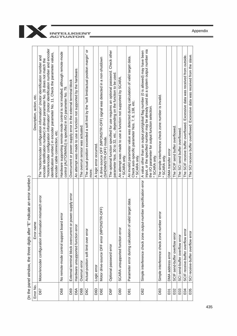
435
Appendix
(In th
e pa
nel w
indo
w, t
he th
ree
digi
ts a
fter “
E” in
dica
te a
n er
ror n
umbe
r.)
Err
or N
o.
Err
or n
ame
Des
crip
tion,
act
ion,
etc
. D
67
Mot
or/e
ncod
er c
onfig
urat
ion
info
rmat
ion
mis
mat
ch e
rror
Th
e “m
otor
/enc
oder
con
figur
atio
n in
form
atio
n” (m
otor
iden
tific
atio
n nu
mbe
r and
en
code
r ide
ntifi
catio
n nu
mbe
r) in
driv
er p
aram
eter
No.
26
does
not
mat
ch th
e “m
otor
/enc
oder
con
figur
atio
n in
form
atio
n” (m
otor
iden
tific
atio
n nu
mbe
r and
enc
oder
id
entif
icat
ion
num
ber)
in e
ncod
er p
aram
eter
No.
11.
Che
ck th
e pa
ram
eter
val
ues,
en
code
r cab
le c
onne
ctio
n, e
tc.
D68
N
o re
mot
e-m
ode
cont
rol s
uppo
rt bo
ard
erro
r H
ardw
are
supp
ortin
g re
mot
e-m
ode
cont
rol i
s no
t ins
talle
d, a
lthou
gh re
mot
e-m
ode
cont
rol (
AUTO
/MAN
U) i
s sp
ecifi
ed in
I/O
par
amet
er N
o. 7
9.
D69
E
xter
nal t
erm
inal
blo
ck o
verc
urre
nt o
r pow
er-s
uppl
y er
ror
Ove
rcur
rent
or p
ower
-sup
ply
erro
r in
the
exte
rnal
term
inal
blo
ck
D6A
H
ardw
are
unsu
ppor
ted
func
tion
erro
r A
n at
tem
pt w
as m
ade
to u
se a
func
tion
not s
uppo
rted
by th
e ha
rdw
are.
D
6B
Ove
rrun
err
or
The
over
run
sens
or w
as a
ctua
ted.
D
6C
Act
ual-p
ositi
on s
oft l
imit
over
err
or
The
actu
al p
ositi
on e
xcee
ded
a so
ft lim
it by
the
“sof
t lim
it/ac
tual
pos
ition
mar
gin”
or
mor
e.
D6D
Lo
gic
erro
r A
logi
c er
ror o
ccur
red.
D
6E
Mot
or d
rive-
sour
ce O
FF e
rror (
MP
ON
STR
-OFF
) A
driv
e-so
urce
OFF
(MPO
NS
TR-O
FF) s
igna
l was
det
ecte
d in
a n
on-s
hutd
own
(SH
DW
NST
R-O
FF) m
ode.
D
6F
Opt
iona
l pas
swor
d er
ror
The
optio
nal f
unct
ion
spec
ified
for u
se re
quire
s an
opt
iona
l pas
swor
d. C
heck
oth
er
para
met
er N
os. 3
0 to
32,
etc
., de
pend
ing
on th
e fu
nctio
n to
be
used
. D
80
SC
AR
A u
nsup
porte
d fu
nctio
n er
ror
An
atte
mpt
was
mad
e to
use
a fu
nctio
n no
t sup
porte
d by
SC
AR
A.
* S
CA
RA
onl
y.
D81
P
aram
eter
err
or d
urin
g ca
lcul
atio
n of
val
id ta
rget
dat
a A
n in
valid
par
amet
er v
alue
was
det
ecte
d du
ring
calc
ulat
ion
of v
alid
targ
et d
ata.
C
heck
axi
s-sp
ecifi
c pa
ram
eter
Nos
. 7, 8
, 138
, etc
. *
SC
AR
A o
nly.
D
82
Sim
ple
inte
rfere
nce
chec
k zo
ne o
utpu
t-num
ber s
peci
ficat
ion
erro
rA
valu
e ot
her t
han
an o
utpu
t por
t/glo
bal f
lag
num
ber (
0 is
allo
wed
) may
hav
e be
en
inpu
t, or
the
spec
ified
num
ber m
ay b
e al
read
y us
ed a
s a
syst
em o
utpu
t num
ber v
ia
the
I/O p
aram
eter
for o
utpu
t fun
ctio
n se
lect
ion.
*
SC
AR
A o
nly.
D
83
Sim
ple
inte
rfere
nce
chec
k zo
ne n
umbe
r err
or
The
sim
ple
inte
rfere
nce
chec
k zo
ne n
umbe
r is
inva
lid.
* S
CA
RA
onl
y.
E01
D
MA
add
ress
erro
r D
MA
tran
sfer
err
or
E02
S
CIF
sen
d-bu
ffer o
verfl
ow e
rror
Th
e S
CIF
sen
d bu
ffer o
verfl
owed
. E
03
SC
I sen
d-bu
ffer o
verfl
ow e
rror
The
SC
I sen
d bu
ffer o
verfl
owed
. E
04
SC
IF re
ceiv
e-bu
ffer o
verfl
ow e
rror
The
SC
IF re
ceiv
e bu
ffer o
verfl
owed
. Exc
essi
ve d
ata
was
rece
ived
from
out
side
. E
05
SC
I rec
eive
-buf
fer o
verfl
ow e
rror
Th
e S
CI r
ecei
ve b
uffe
r ove
rflow
ed. E
xces
sive
dat
a w
as re
ceiv
ed fr
om th
e sl
ave.
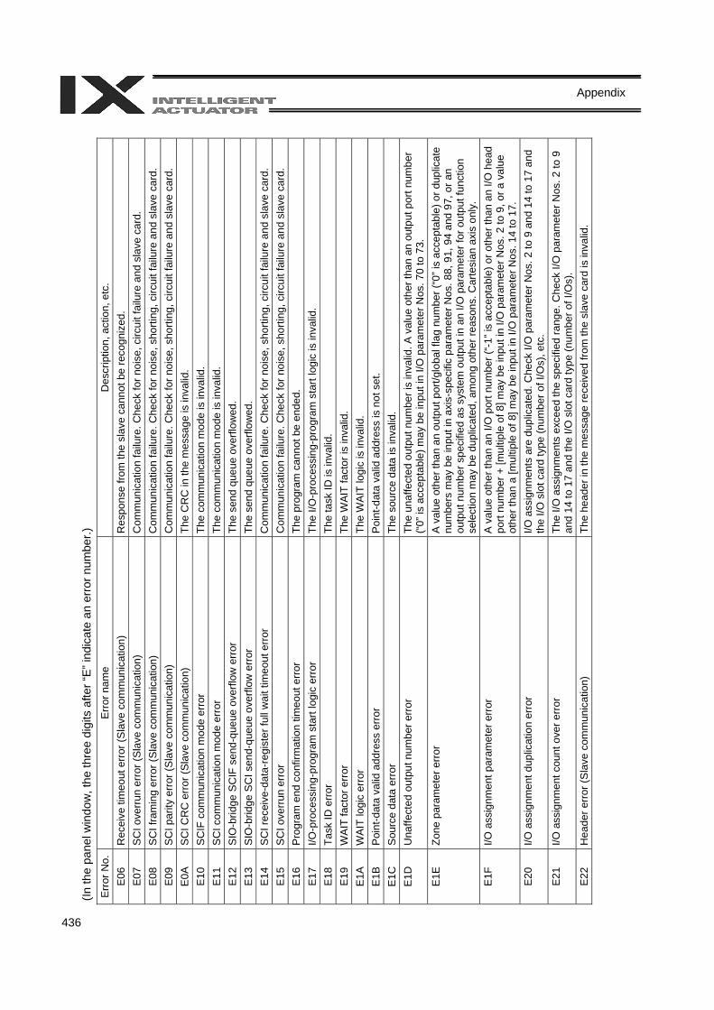
436
Appendix
(In th
e pa
nel w
indo
w, t
he th
ree
digi
ts a
fter “
E” in
dica
te a
n er
ror n
umbe
r.)
Err
or N
o.
Err
or n
ame
Des
crip
tion,
act
ion,
etc
. E
06
Rec
eive
tim
eout
erro
r (S
lave
com
mun
icat
ion)
R
espo
nse
from
the
slav
e ca
nnot
be
reco
gniz
ed.
E07
S
CI o
verru
n er
ror (
Sla
ve c
omm
unic
atio
n)
Com
mun
icat
ion
failu
re. C
heck
for n
oise
, circ
uit f
ailu
re a
nd s
lave
car
d.
E08
S
CI f
ram
ing
erro
r (S
lave
com
mun
icat
ion)
C
omm
unic
atio
n fa
ilure
. Che
ck fo
r noi
se, s
horti
ng, c
ircui
t fai
lure
and
sla
ve c
ard.
E
09
SC
I par
ity e
rror (
Sla
ve c
omm
unic
atio
n)
Com
mun
icat
ion
failu
re. C
heck
for n
oise
, sho
rting
, circ
uit f
ailu
re a
nd s
lave
car
d.
E0A
S
CI C
RC
err
or (S
lave
com
mun
icat
ion)
Th
e C
RC
in th
e m
essa
ge is
inva
lid.
E10
S
CIF
com
mun
icat
ion
mod
e er
ror
The
com
mun
icat
ion
mod
e is
inva
lid.
E11
S
CI c
omm
unic
atio
n m
ode
erro
r Th
e co
mm
unic
atio
n m
ode
is in
valid
. E
12
SIO
-brid
ge S
CIF
sen
d-qu
eue
over
flow
err
or
The
send
que
ue o
verfl
owed
. E
13
SIO
-brid
ge S
CI s
end-
queu
e ov
erflo
w e
rror
The
send
que
ue o
verfl
owed
. E
14
SC
I rec
eive
-dat
a-re
gist
er fu
ll w
ait t
imeo
ut e
rror
C
omm
unic
atio
n fa
ilure
. Che
ck fo
r noi
se, s
horti
ng, c
ircui
t fai
lure
and
sla
ve c
ard.
E
15
SC
I ove
rrun
erro
r C
omm
unic
atio
n fa
ilure
. Che
ck fo
r noi
se, s
horti
ng, c
ircui
t fai
lure
and
sla
ve c
ard.
E
16
Pro
gram
end
con
firm
atio
n tim
eout
erro
r Th
e pr
ogra
m c
anno
t be
ende
d.
E17
I/O
-pro
cess
ing-
prog
ram
sta
rt lo
gic
erro
r Th
e I/O
-pro
cess
ing-
prog
ram
sta
rt lo
gic
is in
valid
. E
18
Task
ID e
rror
The
task
ID is
inva
lid.
E19
W
AIT
fact
or e
rror
Th
e W
AIT
fact
or is
inva
lid.
E1A
W
AIT
logi
c er
ror
The
WAI
T lo
gic
is in
valid
. E
1B
Poi
nt-d
ata
valid
add
ress
err
or
Poi
nt-d
ata
valid
add
ress
is n
ot s
et.
E1C
S
ourc
e da
ta e
rror
Th
e so
urce
dat
a is
inva
lid.
E1D
U
naffe
cted
out
put n
umbe
r err
or
The
unaf
fect
ed o
utpu
t num
ber i
s in
valid
. A v
alue
oth
er th
an a
n ou
tput
por
t num
ber
(“0”
is a
ccep
tabl
e) m
ay b
e in
put i
n I/O
par
amet
er N
os. 7
0 to
73.
E
1E
Zone
par
amet
er e
rror
A
val
ue o
ther
than
an
outp
ut p
ort/g
loba
l fla
g nu
mbe
r (“0
” is
acce
ptab
le) o
r dup
licat
e nu
mbe
rs m
ay b
e in
put i
n ax
is-s
peci
fic p
aram
eter
Nos
. 88,
91,
94
and
97, o
r an
outp
ut n
umbe
r spe
cifie
d as
sys
tem
out
put i
n an
I/O
par
amet
er fo
r out
put f
unct
ion
sele
ctio
n m
ay b
e du
plic
ated
, am
ong
othe
r rea
sons
. Car
tesi
an a
xis
only
. E
1F
I/O a
ssig
nmen
t par
amet
er e
rror
A
val
ue o
ther
than
an
I/O p
ort n
umbe
r (“-
1” is
acc
epta
ble)
or o
ther
than
an
I/O h
ead
port
num
ber +
[mul
tiple
of 8
] may
be
inpu
t in
I/O p
aram
eter
Nos
. 2 to
9, o
r a v
alue
ot
her t
han
a [m
ultip
le o
f 8] m
ay b
e in
put i
n I/O
par
amet
er N
os. 1
4 to
17.
E
20
I/O a
ssig
nmen
t dup
licat
ion
erro
r I/O
ass
ignm
ents
are
dup
licat
ed. C
heck
I/O
par
amet
er N
os. 2
to 9
and
14
to 1
7 an
d th
e I/O
slo
t car
d ty
pe (n
umbe
r of I
/Os)
, etc
. E
21
I/O a
ssig
nmen
t cou
nt o
ver e
rror
Th
e I/O
ass
ignm
ents
exc
eed
the
spec
ified
rang
e. C
heck
I/O
par
amet
er N
os. 2
to 9
an
d 14
to 1
7 an
d th
e I/O
slo
t car
d ty
pe (n
umbe
r of I
/Os)
. E
22
Hea
der e
rror
(Sla
ve c
omm
unic
atio
n)
The
head
er in
the
mes
sage
rece
ived
from
the
slav
e ca
rd is
inva
lid.
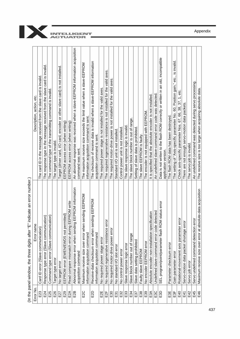
437
Appendix
(In th
e pa
nel w
indo
w, t
he th
ree
digi
ts a
fter “
E” in
dica
te a
n er
ror n
umbe
r.)
Err
or N
o.
Err
or n
ame
Des
crip
tion,
act
ion,
etc
. E
23
Car
d ID
err
or (S
lave
com
mun
icat
ion)
Th
e ca
rd ID
in th
e m
essa
ge re
ceiv
ed fr
om th
e sl
ave
card
is in
valid
. E
24
Res
pons
e ty
pe e
rror (
Sla
ve c
omm
unic
atio
n)
The
resp
onse
type
in th
e m
essa
ge re
ceiv
ed fr
om th
e sl
ave
card
is in
valid
. E
25
Com
man
d ty
pe e
rror (
Sla
ve c
omm
unic
atio
n)
The
com
man
d ty
pe o
f the
tran
smitt
ing
com
man
d is
inva
lid.
E26
Ta
rget
type
err
or
The
targ
et ty
pe is
inva
lid.
E27
N
o ta
rget
err
or
Targ
et (d
river
car
d, I/
O c
ard,
enc
oder
or o
ther
sla
ve c
ard)
is n
ot in
stal
led.
E
29
EE
PR
OM
erro
r (E
WE
N/E
WD
S no
t per
mitt
ed)
EE
PR
OM
acc
ess
erro
r (w
hen
writ
ing)
E
2A
Rea
d co
mpa
re m
ism
atch
erro
r dur
ing
EE
PR
OM
writ
e E
EP
RO
M a
cces
s er
ror (
whe
n w
ritin
g)
E2B
A
bnor
mal
resp
onse
err
or w
hen
send
ing
EE
PR
OM
info
rmat
ion
acqu
isiti
on c
omm
and
An
abno
rmal
resp
onse
was
rece
ived
whe
n a
slav
e-E
EP
RO
M in
form
atio
n ac
quis
ition
co
mm
and
was
sen
t. E
2C
Max
imum
rece
ive
size
ove
r err
or w
hen
send
ing
EE
PR
OM
in
form
atio
n ac
quis
ition
com
man
d Th
e m
axim
um re
ceiv
e si
ze e
xcee
ds th
e lim
it va
lue
whe
n a
slav
e-E
EPR
OM
in
form
atio
n ac
quis
ition
com
man
d is
sen
t. E
2D
Rec
eive
-dat
a ch
ecks
um e
rror w
hen
send
ing
EE
PR
OM
in
form
atio
n ac
quis
ition
com
man
d Th
e ch
ecks
um o
f rec
eive
dat
a is
inva
lid w
hen
a sl
ave-
EE
PR
OM
info
rmat
ion
acqu
isiti
on c
omm
and
is s
ent.
E2E
N
o re
quire
d po
wer
sta
ge e
rror
Th
e re
quire
d po
wer
sta
ge is
not
inst
alle
d fo
r the
val
id a
xes.
E
2F
No
requ
ired
rege
nera
tive
resi
stan
ce e
rror
Th
e re
quire
d re
gene
rativ
e re
sist
ance
is n
ot in
stal
led
for t
he v
alid
axe
s.
E30
N
o re
quire
d m
otor
-driv
e po
wer
erro
r Th
e re
quire
d m
otor
-driv
e po
wer
is n
ot in
stal
led
for t
he v
alid
axe
s.
E31
N
o st
anda
rd I/
O s
lot e
rror
S
tand
ard
I/O u
nit i
s no
t ins
talle
d.
E32
N
o co
ntro
l pow
er e
rror
Con
trol p
ower
uni
t is
not i
nsta
lled.
E
33
Sla
ve re
spon
se lo
gic
erro
r Th
e sl
ave
resp
onse
logi
c is
inva
lid.
E34
S
lave
blo
ck n
umbe
r out
of r
ange
Th
e sl
ave
bloc
k nu
mbe
r is
out o
f ran
ge.
E37
S
lave
dat
a se
tting
pro
hibi
ted
Set
ting
of s
lave
dat
a is
pro
hibi
ted.
E
38
Faul
ty s
lave
EE
PRO
M
The
slav
e E
EP
RO
M is
faul
ty.
E39
N
o en
code
r EE
PR
OM
erro
r Th
e en
code
r is
not e
quip
ped
with
EE
PR
OM
. E
3A
Abs
olut
e en
code
r non
-inst
alla
tion
spec
ifica
tion
It is
spe
cifie
d th
at th
e ab
solu
te e
ncod
er is
not
inst
alle
d.
E3C
U
ndef
ined
sla
ve-c
omm
and
erro
r cod
e de
tect
ed
An
unde
fined
sla
ve-c
omm
and
erro
r cod
e w
as d
etec
ted.
E
3D
SEL
pro
gram
/poi
nt/p
aram
eter
flas
h R
OM
sta
tus
erro
r D
ata
is n
ot w
ritte
n to
the
flash
RO
M c
orre
ctly
or w
ritte
n in
an
old,
inco
mpa
tible
ap
plic
atio
n ve
rsio
n.
E3E
P
aram
eter
che
cksu
m e
rror
Th
e fla
sh R
OM
dat
a ha
s be
en d
estro
yed.
E
3F
Gai
n pa
ram
eter
err
or
The
setti
ng o
f “A
xis-
spec
ific
para
met
er N
o. 6
0, P
ositi
on g
ain,
” etc
., is
inva
lid.
E40
R
otat
iona
l-mov
emen
t axi
s pa
ram
eter
err
or
Che
ck a
xis-
spec
ific
para
met
er N
os. 6
7, 6
6, 3
8, 3
7, 1
, etc
. E
41
Ser
vo-m
otio
n da
ta p
acke
t sho
rtage
erro
r Th
ere
are
not e
noug
h se
rvo-
mot
ion
data
pac
kets
. E
42
Ser
vo jo
b er
ror
The
serv
o jo
b is
inva
lid.
E45
S
ervo
und
efin
ed c
omm
and
dete
ctio
n er
ror
An
unde
fined
com
man
d w
as d
etec
ted
durin
g se
rvo
proc
essi
ng.
E46
M
axim
um re
ceiv
e si
ze o
ver e
rror
at a
bsol
ute-
data
acq
uisi
tion
The
rece
ive
size
is to
o la
rge
whe
n ac
quiri
ng a
bsol
ute
data
.
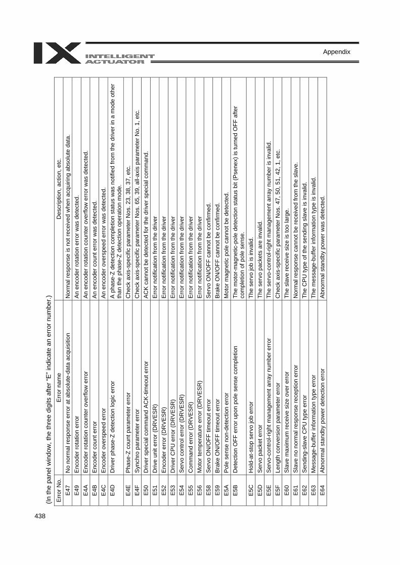
438
Appendix
(In th
e pa
nel w
indo
w, t
he th
ree
digi
ts a
fter “
E” in
dica
te a
n er
ror n
umbe
r.)
Err
or N
o.
Err
or n
ame
Des
crip
tion,
act
ion,
etc
. E
47
No
norm
al re
spon
se e
rror
at a
bsol
ute-
data
acq
uisi
tion
Nor
mal
resp
onse
is n
ot re
ceiv
ed w
hen
acqu
iring
abs
olut
e da
ta.
E49
E
ncod
er ro
tatio
n er
ror
An
enco
der r
otat
ion
erro
r was
det
ecte
d.
E4A
E
ncod
er ro
tatio
n co
unte
r ove
rflow
err
or
An
enco
der r
otat
ion
coun
ter o
verfl
ow e
rror
was
det
ecte
d.
E4B
E
ncod
er c
ount
err
or
An
enco
der c
ount
err
or w
as d
etec
ted.
E
4C
Enc
oder
ove
rspe
ed e
rror
A
n en
code
r ove
rspe
ed e
rror
was
det
ecte
d.
E4D
D
river
pha
se-Z
det
ectio
n lo
gic
erro
r A
pha
se-Z
det
ectio
n co
mpl
etio
n st
atus
was
not
ified
from
the
driv
er in
a m
ode
othe
r th
an th
e ph
ase-
Z de
tect
ion
oper
atio
n m
ode.
E
4E
Pha
se-Z
cou
nt p
aram
eter
erro
r C
heck
axi
s-sp
ecifi
c pa
ram
eter
Nos
. 23,
38,
37,
etc
. E
4F
Syn
chro
par
amet
er e
rror
Che
ck a
xis-
spec
ific
para
met
er N
os. 6
5, 3
9, a
ll-ax
is p
aram
eter
No.
1, e
tc.
E50
D
river
spe
cial
com
man
d A
CK
-tim
eout
erro
r A
CK
can
not b
e de
tect
ed fo
r the
driv
er s
peci
al c
omm
and.
E
51
Driv
e un
it er
ror (
DR
VE
SR
) E
rror n
otifi
catio
n fro
m th
e dr
iver
E
52
Enc
oder
erro
r (D
RV
ES
R)
Erro
r not
ifica
tion
from
the
driv
er
E53
Driv
er C
PU e
rror
(DR
VESR
) Er
ror n
otifi
catio
n fro
m th
e dr
iver
E
54
Ser
vo c
ontro
l erro
r (D
RV
ES
R)
Erro
r not
ifica
tion
from
the
driv
er
E55
C
omm
and
erro
r (D
RV
ES
R)
Erro
r not
ifica
tion
from
the
driv
er
E56
M
otor
tem
pera
ture
err
or (D
RV
ESR
) Er
ror n
otifi
catio
n fro
m th
e dr
iver
E
58
Ser
vo O
N/O
FF ti
meo
ut e
rror
Ser
vo O
N/O
FF c
anno
t be
conf
irmed
. E
59
Bra
ke O
N/O
FF ti
meo
ut e
rror
Bra
ke O
N/O
FF c
anno
t be
conf
irmed
. E
5A
Pol
e se
nse
non-
dete
ctio
n er
ror
Mot
or m
agne
tic p
ole
cann
ot b
e de
tect
ed.
E5B
D
etec
tion
OFF
err
or u
pon
pole
sen
se c
ompl
etio
n Th
e m
otor
-mag
netic
-pol
e de
tect
ion
stat
us b
it (P
sene
x) is
turn
ed O
FF a
fter
com
plet
ion
of p
ole
sens
e.
E5C
H
old-
at-s
top
serv
o jo
b er
ror
The
serv
o jo
b is
inva
lid.
E5D
S
ervo
pac
ket e
rror
Th
e se
rvo
pack
ets
are
inva
lid.
E5E
S
ervo
-con
trol-r
ight
man
agem
ent a
rray
num
ber e
rror
The
serv
o-co
ntro
l-rig
ht m
anag
emen
t arr
ay n
umbe
r is
inva
lid.
E5F
Le
ngth
con
vers
ion
para
met
er e
rror
Che
ck a
xis-
spec
ific
para
met
er N
os. 4
7, 5
0, 5
1, 4
2, 1
, etc
. E
60
Sla
ve m
axim
um re
ceiv
e si
ze o
ver e
rror
Th
e sl
ave
rece
ive
size
is to
o la
rge.
E
61
Sla
ve n
o no
rmal
resp
onse
rece
ptio
n er
ror
Nor
mal
resp
onse
can
not b
e re
ceiv
ed fr
om th
e sl
ave.
E
62
Sen
ding
-sla
ve C
PU
type
erro
r Th
e C
PU
type
of t
he s
endi
ng s
lave
is in
valid
. E
63
Mes
sage
-buf
fer i
nfor
mat
ion
type
erro
r Th
e m
essa
ge-b
uffe
r inf
orm
atio
n ty
pe is
inva
lid.
E64
A
bnor
mal
sta
ndby
pow
er d
etec
tion
erro
r A
bnor
mal
sta
ndby
pow
er w
as d
etec
ted.
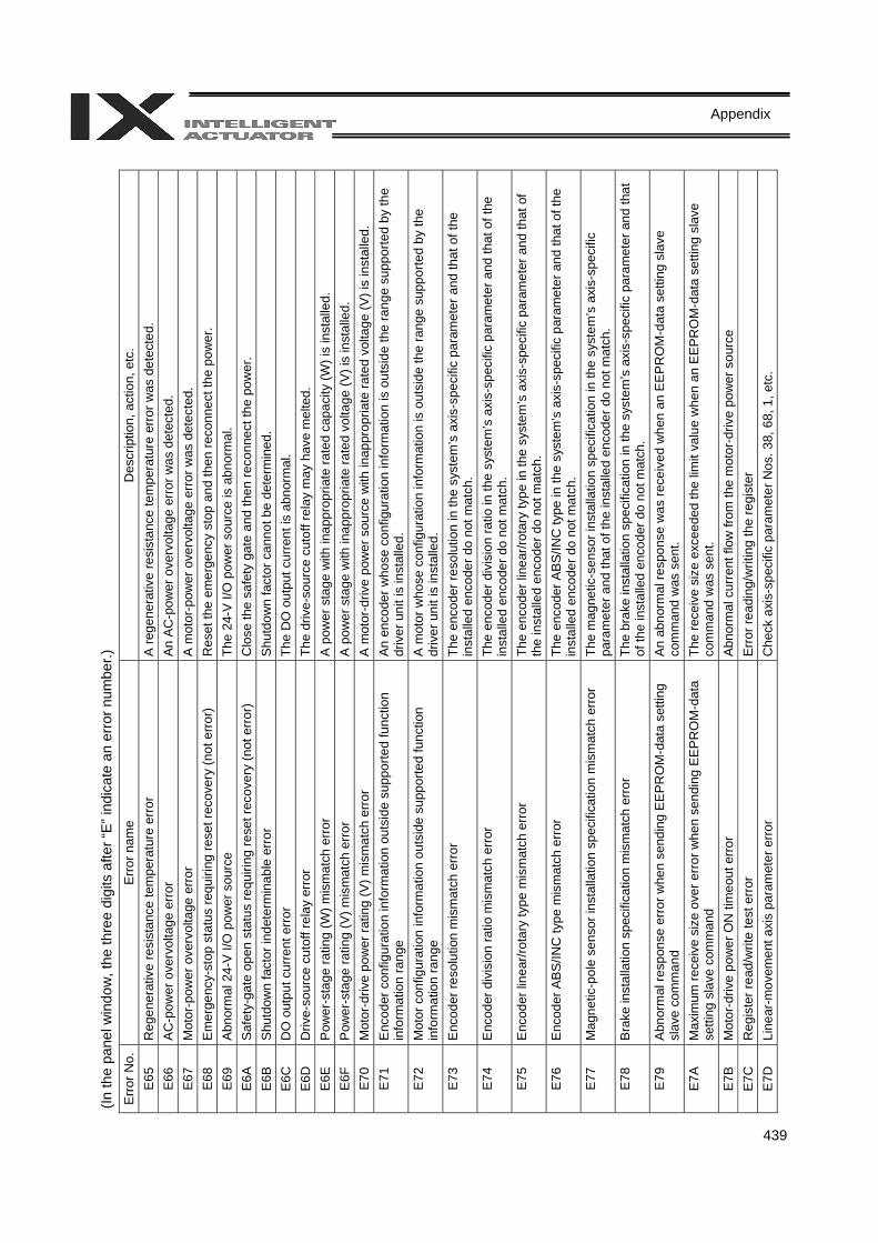
439
Appendix
(In th
e pa
nel w
indo
w, t
he th
ree
digi
ts a
fter “
E” in
dica
te a
n er
ror n
umbe
r.)
Err
or N
o.
Err
or n
ame
Des
crip
tion,
act
ion,
etc
. E
65
Reg
ener
ativ
e re
sist
ance
tem
pera
ture
err
or
A re
gene
rativ
e re
sist
ance
tem
pera
ture
err
or w
as d
etec
ted.
E
66
AC
-pow
er o
verv
olta
ge e
rror
An
AC
-pow
er o
verv
olta
ge e
rror
was
det
ecte
d.
E67
M
otor
-pow
er o
verv
olta
ge e
rror
A
mot
or-p
ower
ove
rvol
tage
err
or w
as d
etec
ted.
E
68
Em
erge
ncy-
stop
sta
tus
requ
iring
rese
t rec
over
y (n
ot e
rror)
R
eset
the
emer
genc
y st
op a
nd th
en re
conn
ect t
he p
ower
. E
69
Abn
orm
al 2
4-V
I/O
pow
er s
ourc
e Th
e 24
-V I/
O p
ower
sou
rce
is a
bnor
mal
. E
6A
Saf
ety-
gate
ope
n st
atus
requ
iring
rese
t rec
over
y (n
ot e
rror
) C
lose
the
safe
ty g
ate
and
then
reco
nnec
t the
pow
er.
E6B
S
hutd
own
fact
or in
dete
rmin
able
erro
r S
hutd
own
fact
or c
anno
t be
dete
rmin
ed.
E6C
D
O o
utpu
t cur
rent
err
or
The
DO
out
put c
urre
nt is
abn
orm
al.
E6D
D
rive-
sour
ce c
utof
f rel
ay e
rror
Th
e dr
ive-
sour
ce c
utof
f rel
ay m
ay h
ave
mel
ted.
E
6E
Pow
er-s
tage
ratin
g (W
) mis
mat
ch e
rror
A p
ower
sta
ge w
ith in
appr
opria
te ra
ted
capa
city
(W) i
s in
stal
led.
E
6F
Pow
er-s
tage
ratin
g (V
) mis
mat
ch e
rror
A p
ower
sta
ge w
ith in
appr
opria
te ra
ted
volta
ge (V
) is
inst
alle
d.
E70
M
otor
-driv
e po
wer
ratin
g (V
) mis
mat
ch e
rror
A m
otor
-driv
e po
wer
sou
rce
with
inap
prop
riate
rate
d vo
ltage
(V) i
s in
stal
led.
E
71
Enc
oder
con
figur
atio
n in
form
atio
n ou
tsid
e su
ppor
ted
func
tion
info
rmat
ion
rang
e A
n en
code
r who
se c
onfig
urat
ion
info
rmat
ion
is o
utsi
de th
e ra
nge
supp
orte
d by
the
driv
er u
nit i
s in
stal
led.
E
72
Mot
or c
onfig
urat
ion
info
rmat
ion
outs
ide
supp
orte
d fu
nctio
n in
form
atio
n ra
nge
A m
otor
who
se c
onfig
urat
ion
info
rmat
ion
is o
utsi
de th
e ra
nge
supp
orte
d by
the
driv
er u
nit i
s in
stal
led.
E
73
Enc
oder
reso
lutio
n m
ism
atch
erro
r Th
e en
code
r res
olut
ion
in th
e sy
stem
’s a
xis-
spec
ific
para
met
er a
nd th
at o
f the
in
stal
led
enco
der d
o no
t mat
ch.
E74
E
ncod
er d
ivis
ion
ratio
mis
mat
ch e
rror
The
enco
der d
ivis
ion
ratio
in th
e sy
stem
’s a
xis-
spec
ific
para
met
er a
nd th
at o
f the
in
stal
led
enco
der d
o no
t mat
ch.
E75
E
ncod
er li
near
/rota
ry ty
pe m
ism
atch
err
or
The
enco
der l
inea
r/rot
ary
type
in th
e sy
stem
’s a
xis-
spec
ific
para
met
er a
nd th
at o
f th
e in
stal
led
enco
der d
o no
t mat
ch.
E76
E
ncod
er A
BS
/INC
type
mis
mat
ch e
rror
Th
e en
code
r AB
S/IN
C ty
pe in
the
syst
em’s
axi
s-sp
ecifi
c pa
ram
eter
and
that
of t
he
inst
alle
d en
code
r do
not m
atch
. E
77
Mag
netic
-pol
e se
nsor
inst
alla
tion
spec
ifica
tion
mis
mat
ch e
rror
Th
e m
agne
tic-s
enso
r ins
talla
tion
spec
ifica
tion
in th
e sy
stem
’s a
xis-
spec
ific
para
met
er a
nd th
at o
f the
inst
alle
d en
code
r do
not m
atch
. E
78
Bra
ke in
stal
latio
n sp
ecifi
catio
n m
ism
atch
erro
r Th
e br
ake
inst
alla
tion
spec
ifica
tion
in th
e sy
stem
’s a
xis-
spec
ific
para
met
er a
nd th
at
of th
e in
stal
led
enco
der d
o no
t mat
ch.
E79
A
bnor
mal
resp
onse
err
or w
hen
send
ing
EE
PR
OM
-dat
a se
tting
sl
ave
com
man
d A
n ab
norm
al re
spon
se w
as re
ceiv
ed w
hen
an E
EP
RO
M-d
ata
setti
ng s
lave
co
mm
and
was
sen
t. E
7A
Max
imum
rece
ive
size
ove
r err
or w
hen
send
ing
EE
PR
OM
-dat
a se
tting
sla
ve c
omm
and
The
rece
ive
size
exc
eede
d th
e lim
it va
lue
whe
n an
EEP
RO
M-d
ata
setti
ng s
lave
co
mm
and
was
sen
t. E
7B
Mot
or-d
rive
pow
er O
N ti
meo
ut e
rror
Abn
orm
al c
urre
nt fl
ow fr
om th
e m
otor
-driv
e po
wer
sou
rce
E7C
R
egis
ter r
ead/
writ
e te
st e
rror
E
rror r
eadi
ng/w
ritin
g th
e re
gist
er
E7D
Li
near
-mov
emen
t axi
s pa
ram
eter
err
or
Che
ck a
xis-
spec
ific
para
met
er N
os. 3
8, 6
8, 1
, etc
.
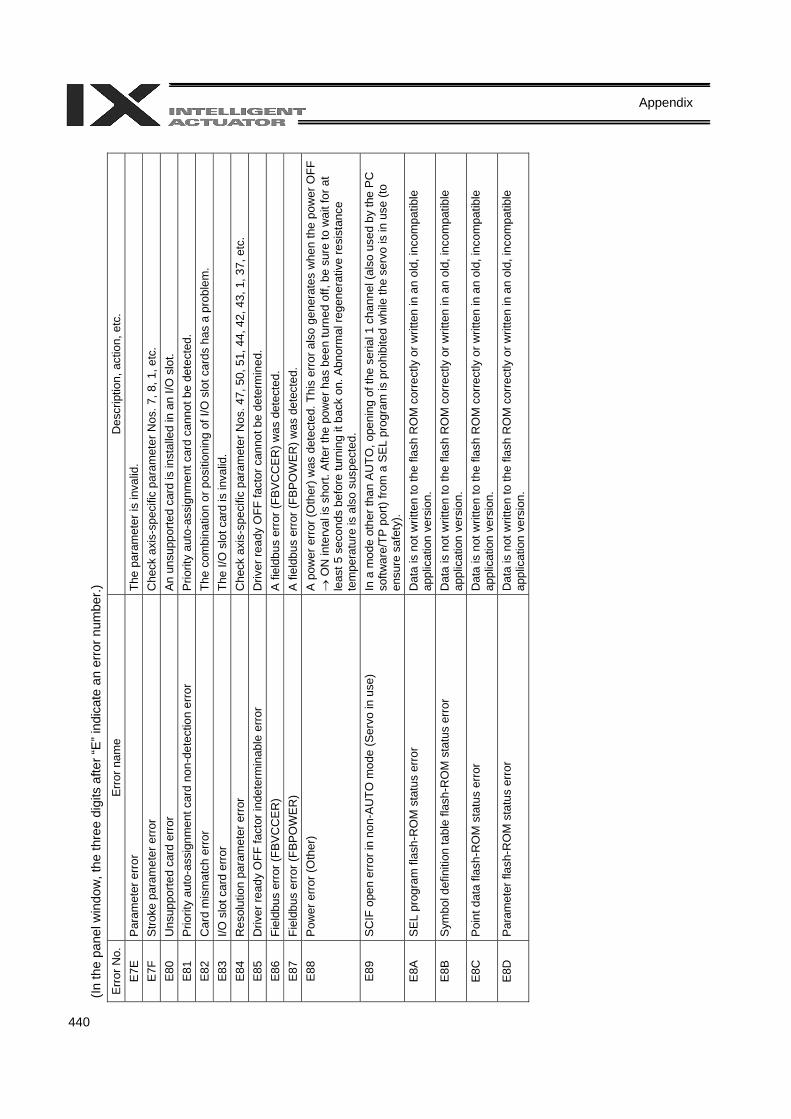
440
Appendix
(In th
e pa
nel w
indo
w, t
he th
ree
digi
ts a
fter “
E” in
dica
te a
n er
ror n
umbe
r.)
Err
or N
o.
Err
or n
ame
Des
crip
tion,
act
ion,
etc
. E
7E
Par
amet
er e
rror
Th
e pa
ram
eter
is in
valid
. E
7F
Stro
ke p
aram
eter
erro
r C
heck
axi
s-sp
ecifi
c pa
ram
eter
Nos
. 7, 8
, 1, e
tc.
E80
U
nsup
porte
d ca
rd e
rror
A
n un
supp
orte
d ca
rd is
inst
alle
d in
an
I/O s
lot.
E81
P
riorit
y au
to-a
ssig
nmen
t car
d no
n-de
tect
ion
erro
r P
riorit
y au
to-a
ssig
nmen
t car
d ca
nnot
be
dete
cted
. E
82
Car
d m
ism
atch
err
or
The
com
bina
tion
or p
ositi
onin
g of
I/O
slo
t car
ds h
as a
pro
blem
. E
83
I/O s
lot c
ard
erro
r Th
e I/O
slo
t car
d is
inva
lid.
E84
R
esol
utio
n pa
ram
eter
err
or
Che
ck a
xis-
spec
ific
para
met
er N
os. 4
7, 5
0, 5
1, 4
4, 4
2, 4
3, 1
, 37,
etc
. E
85
Driv
er re
ady
OFF
fact
or in
dete
rmin
able
err
or
Driv
er re
ady
OFF
fact
or c
anno
t be
dete
rmin
ed.
E86
Fi
eldb
us e
rror (
FBV
CC
ER
) A
fiel
dbus
err
or (F
BVC
CE
R) w
as d
etec
ted.
E
87
Fiel
dbus
err
or (F
BP
OW
ER
) A
fiel
dbus
err
or (F
BP
OW
ER
) was
det
ecte
d.
E88
P
ower
err
or (O
ther
) A
pow
er e
rror
(Oth
er) w
as d
etec
ted.
Thi
s er
ror a
lso
gene
rate
s w
hen
the
pow
er O
FF
→ O
N in
terv
al is
sho
rt. A
fter t
he p
ower
has
bee
n tu
rned
off,
be
sure
to w
ait f
or a
t le
ast 5
sec
onds
bef
ore
turn
ing
it ba
ck o
n. A
bnor
mal
rege
nera
tive
resi
stan
ce
tem
pera
ture
is a
lso
susp
ecte
d.
E89
S
CIF
ope
n er
ror i
n no
n-A
UTO
mod
e (S
ervo
in u
se)
In a
mod
e ot
her t
han
AU
TO, o
peni
ng o
f the
ser
ial 1
cha
nnel
(als
o us
ed b
y th
e PC
so
ftwar
e/TP
por
t) fro
m a
SE
L pr
ogra
m is
pro
hibi
ted
whi
le th
e se
rvo
is in
use
(to
ensu
re s
afet
y).
E8A
S
EL p
rogr
am fl
ash-
RO
M s
tatu
s er
ror
Dat
a is
not
writ
ten
to th
e fla
sh R
OM
cor
rect
ly o
r writ
ten
in a
n ol
d, in
com
patib
le
appl
icat
ion
vers
ion.
E
8B
Sym
bol d
efin
ition
tabl
e fla
sh-R
OM
sta
tus
erro
r D
ata
is n
ot w
ritte
n to
the
flash
RO
M c
orre
ctly
or w
ritte
n in
an
old,
inco
mpa
tible
ap
plic
atio
n ve
rsio
n.
E8C
P
oint
dat
a fla
sh-R
OM
sta
tus
erro
r D
ata
is n
ot w
ritte
n to
the
flash
RO
M c
orre
ctly
or w
ritte
n in
an
old,
inco
mpa
tible
ap
plic
atio
n ve
rsio
n.
E8D
P
aram
eter
flas
h-R
OM
sta
tus
erro
r D
ata
is n
ot w
ritte
n to
the
flash
RO
M c
orre
ctly
or w
ritte
n in
an
old,
inco
mpa
tible
ap
plic
atio
n ve
rsio
n.
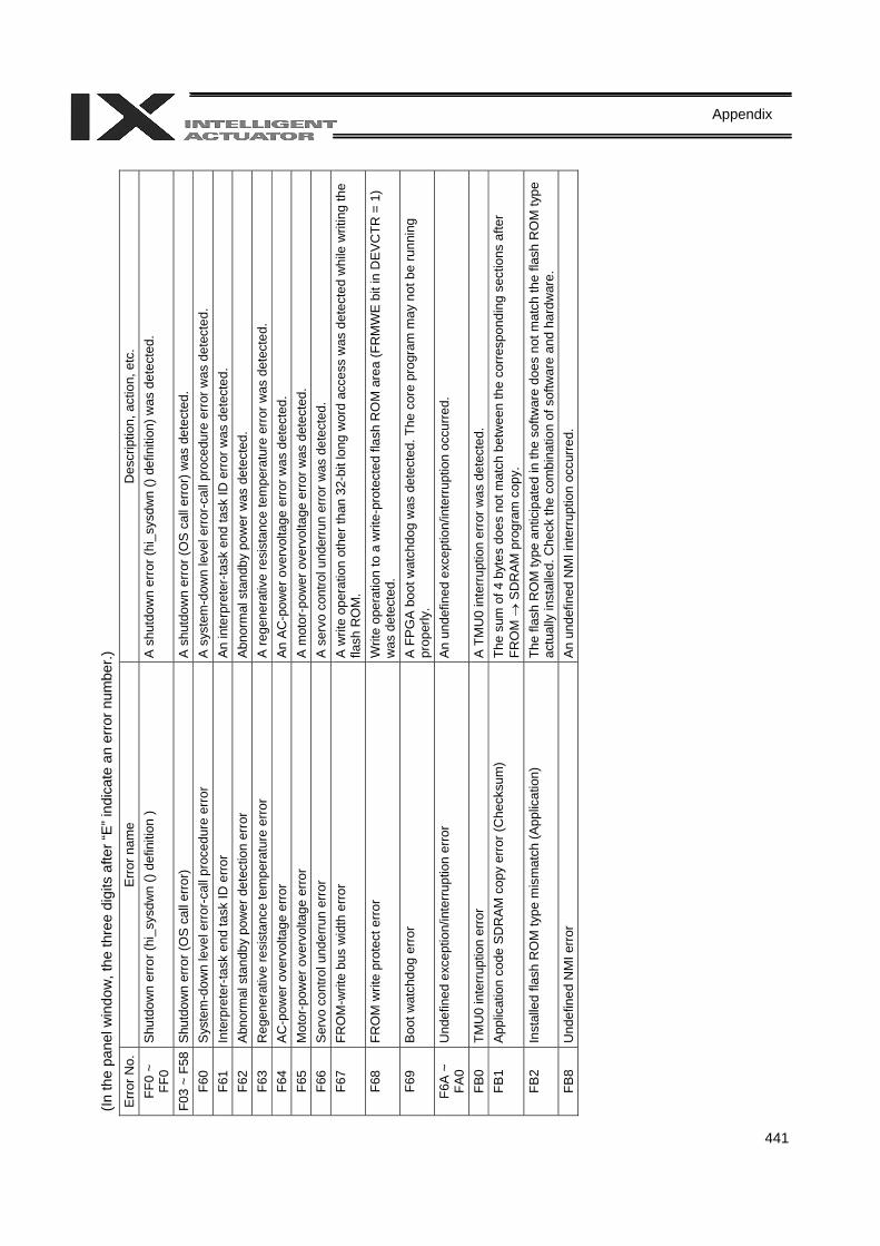
441
Appendix
(In th
e pa
nel w
indo
w, t
he th
ree
digi
ts a
fter “
E” in
dica
te a
n er
ror n
umbe
r.)
Err
or N
o.
Err
or n
ame
Des
crip
tion,
act
ion,
etc
. FF
0 ~
FF0
Shu
tdow
n er
ror (
hi_s
ysdw
n ()
defin
ition
) A
shu
tdow
n er
ror (
hi_s
ysdw
n ()
def
initi
on) w
as d
etec
ted.
F03
~ F5
8S
hutd
own
erro
r (O
S c
all e
rror)
A s
hutd
own
erro
r (O
S c
all e
rror)
was
det
ecte
d.
F60
Sys
tem
-dow
n le
vel e
rror
-cal
l pro
cedu
re e
rror
A
sys
tem
-dow
n le
vel e
rror-c
all p
roce
dure
err
or w
as d
etec
ted.
F6
1 In
terp
rete
r-tas
k en
d ta
sk ID
erro
r An
inte
rpre
ter-
task
end
task
ID e
rror w
as d
etec
ted.
F6
2 A
bnor
mal
sta
ndby
pow
er d
etec
tion
erro
r A
bnor
mal
sta
ndby
pow
er w
as d
etec
ted.
F6
3 R
egen
erat
ive
resi
stan
ce te
mpe
ratu
re e
rror
A
rege
nera
tive
resi
stan
ce te
mpe
ratu
re e
rror
was
det
ecte
d.
F64
AC
-pow
er o
verv
olta
ge e
rror
An
AC
-pow
er o
verv
olta
ge e
rror
was
det
ecte
d.
F65
Mot
or-p
ower
ove
rvol
tage
err
or
A m
otor
-pow
er o
verv
olta
ge e
rror
was
det
ecte
d.
F66
Ser
vo c
ontro
l und
erru
n er
ror
A s
ervo
con
trol u
nder
run
erro
r was
det
ecte
d.
F67
FRO
M-w
rite
bus
wid
th e
rror
A
writ
e op
erat
ion
othe
r tha
n 32
-bit
long
wor
d ac
cess
was
det
ecte
d w
hile
writ
ing
the
flash
RO
M.
F68
FRO
M w
rite
prot
ect e
rror
W
rite
oper
atio
n to
a w
rite-
prot
ecte
d fla
sh R
OM
are
a (F
RM
WE
bit i
n D
EVC
TR =
1)
was
det
ecte
d.
F69
Boo
t wat
chdo
g er
ror
A F
PG
A b
oot w
atch
dog
was
det
ecte
d. T
he c
ore
prog
ram
may
not
be
runn
ing
prop
erly
. F6
A ~
FA
0 U
ndef
ined
exc
eptio
n/in
terru
ptio
n er
ror
An
unde
fined
exc
eptio
n/in
terr
uptio
n oc
curr
ed.
FB0
TMU
0 in
terr
uptio
n er
ror
A T
MU
0 in
terr
uptio
n er
ror w
as d
etec
ted.
FB
1 A
pplic
atio
n co
de S
DR
AM
cop
y er
ror (
Che
cksu
m)
The
sum
of 4
byt
es d
oes
not m
atch
bet
wee
n th
e co
rres
pond
ing
sect
ions
afte
r FR
OM
→ S
DR
AM p
rogr
am c
opy.
FB
2 In
stal
led
flash
RO
M ty
pe m
ism
atch
(App
licat
ion)
Th
e fla
sh R
OM
type
ant
icip
ated
in th
e so
ftwar
e do
es n
ot m
atch
the
flash
RO
M ty
pe
actu
ally
inst
alle
d. C
heck
the
com
bina
tion
of s
oftw
are
and
hard
war
e.
FB8
Und
efin
ed N
MI e
rror
A
n un
defin
ed N
MI i
nter
rupt
ion
occu
rred
.
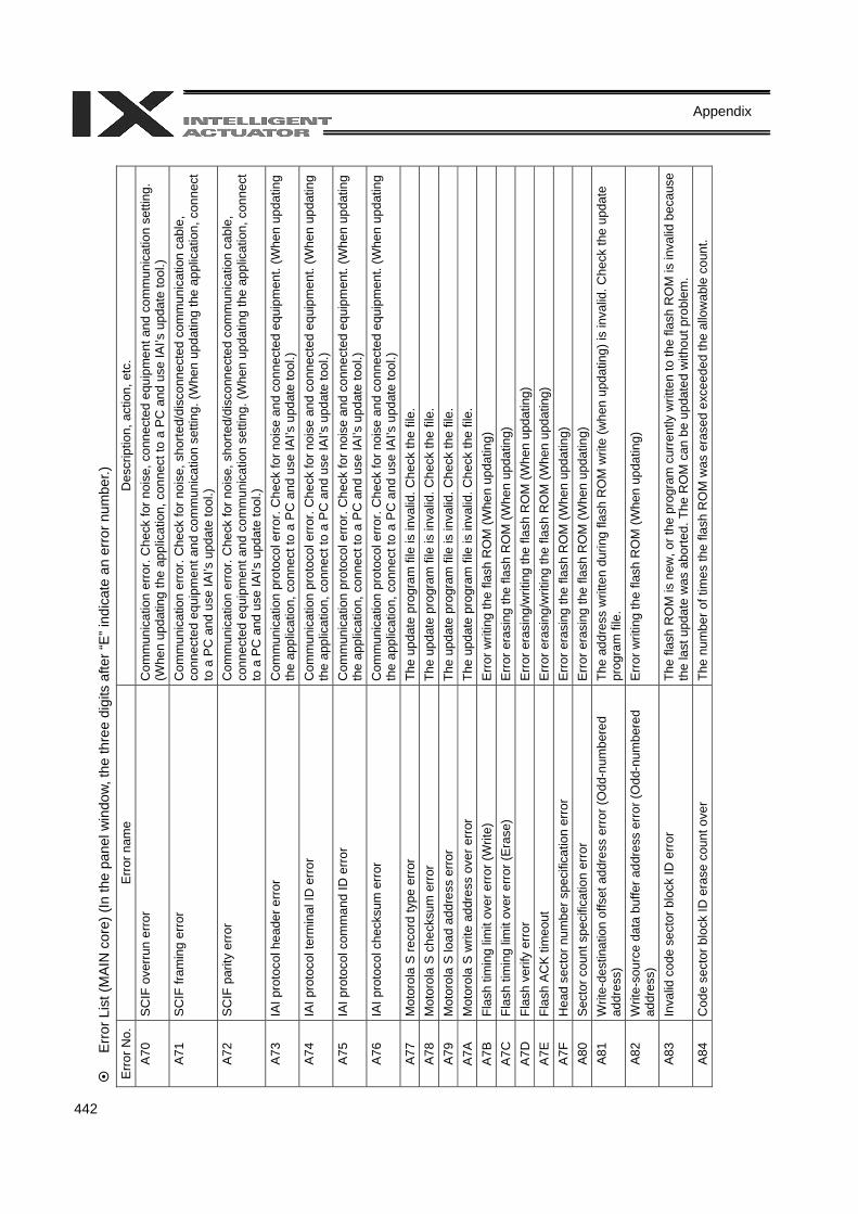
442
Appendix
Erro
r Lis
t (M
AIN
cor
e) (I
n th
e pa
nel w
indo
w, th
e th
ree
digi
ts a
fter “
E” in
dica
te a
n er
ror n
umbe
r.)
Erro
r No.
E
rror n
ame
Des
crip
tion,
act
ion,
etc
. A
70
SC
IF o
verr
un e
rror
Com
mun
icat
ion
erro
r. C
heck
for n
oise
, con
nect
ed e
quip
men
t and
com
mun
icat
ion
setti
ng.
(Whe
n up
datin
g th
e ap
plic
atio
n, c
onne
ct to
a P
C a
nd u
se IA
I’s u
pdat
e to
ol.)
A71
S
CIF
fram
ing
erro
r C
omm
unic
atio
n er
ror.
Che
ck fo
r noi
se, s
horte
d/di
scon
nect
ed c
omm
unic
atio
n ca
ble,
co
nnec
ted
equi
pmen
t and
com
mun
icat
ion
setti
ng. (
Whe
n up
datin
g th
e ap
plic
atio
n, c
onne
ct
to a
PC
and
use
IAI’s
upd
ate
tool
.) A
72
SC
IF p
arity
err
or
Com
mun
icat
ion
erro
r. C
heck
for n
oise
, sho
rted/
disc
onne
cted
com
mun
icat
ion
cabl
e,
conn
ecte
d eq
uipm
ent a
nd c
omm
unic
atio
n se
tting
. (W
hen
upda
ting
the
appl
icat
ion,
con
nect
to
a P
C a
nd u
se IA
I’s u
pdat
e to
ol.)
A73
IA
I pro
toco
l hea
der e
rror
Com
mun
icat
ion
prot
ocol
err
or. C
heck
for n
oise
and
con
nect
ed e
quip
men
t. (W
hen
upda
ting
the
appl
icat
ion,
con
nect
to a
PC
and
use
IAI’s
upd
ate
tool
.) A
74
IAI p
roto
col t
erm
inal
ID e
rror
Com
mun
icat
ion
prot
ocol
err
or. C
heck
for n
oise
and
con
nect
ed e
quip
men
t. (W
hen
upda
ting
the
appl
icat
ion,
con
nect
to a
PC
and
use
IAI’s
upd
ate
tool
.) A
75
IAI p
roto
col c
omm
and
ID e
rror
Com
mun
icat
ion
prot
ocol
err
or. C
heck
for n
oise
and
con
nect
ed e
quip
men
t. (W
hen
upda
ting
the
appl
icat
ion,
con
nect
to a
PC
and
use
IAI’s
upd
ate
tool
.) A
76
IAI p
roto
col c
heck
sum
err
or
Com
mun
icat
ion
prot
ocol
err
or. C
heck
for n
oise
and
con
nect
ed e
quip
men
t. (W
hen
upda
ting
the
appl
icat
ion,
con
nect
to a
PC
and
use
IAI’s
upd
ate
tool
.) A7
7 M
otor
ola
S re
cord
type
err
or
The
upda
te p
rogr
am fi
le is
inva
lid. C
heck
the
file.
A
78
Mot
orol
a S
che
cksu
m e
rror
Th
e up
date
pro
gram
file
is in
valid
. Che
ck th
e fil
e.
A79
M
otor
ola
S lo
ad a
ddre
ss e
rror
Th
e up
date
pro
gram
file
is in
valid
. Che
ck th
e fil
e.
A7A
M
otor
ola
S w
rite
addr
ess
over
err
or
The
upda
te p
rogr
am fi
le is
inva
lid. C
heck
the
file.
A
7B
Flas
h tim
ing
limit
over
err
or (W
rite)
E
rror w
ritin
g th
e fla
sh R
OM
(Whe
n up
datin
g)
A7C
Fl
ash
timin
g lim
it ov
er e
rror
(Era
se)
Err
or e
rasi
ng th
e fla
sh R
OM
(Whe
n up
datin
g)
A7D
Fl
ash
verif
y er
ror
Err
or e
rasi
ng/w
ritin
g th
e fla
sh R
OM
(Whe
n up
datin
g)
A7E
Fl
ash
AC
K ti
meo
ut
Erro
r era
sing
/writ
ing
the
flash
RO
M (W
hen
upda
ting)
A
7F
Hea
d se
ctor
num
ber s
peci
ficat
ion
erro
r E
rror
era
sing
the
flash
RO
M (W
hen
upda
ting)
A
80
Sec
tor c
ount
spe
cific
atio
n er
ror
Err
or e
rasi
ng th
e fla
sh R
OM
(Whe
n up
datin
g)
A81
W
rite-
dest
inat
ion
offs
et a
ddre
ss e
rror
(Odd
-num
bere
d ad
dres
s)
The
addr
ess
writ
ten
durin
g fla
sh R
OM
writ
e (w
hen
upda
ting)
is in
valid
. Che
ck th
e up
date
pr
ogra
m fi
le.
A82
W
rite-
sour
ce d
ata
buffe
r add
ress
err
or (O
dd-n
umbe
red
addr
ess)
E
rror w
ritin
g th
e fla
sh R
OM
(Whe
n up
datin
g)
A83
In
valid
cod
e se
ctor
blo
ck ID
erro
r Th
e fla
sh R
OM
is n
ew, o
r the
pro
gram
cur
rent
ly w
ritte
n to
the
flash
RO
M is
inva
lid b
ecau
se
the
last
upd
ate
was
abo
rted.
The
RO
M c
an b
e up
date
d w
ithou
t pro
blem
. A
84
Cod
e se
ctor
blo
ck ID
era
se c
ount
ove
r Th
e nu
mbe
r of t
imes
the
flash
RO
M w
as e
rase
d ex
ceed
ed th
e al
low
able
cou
nt.
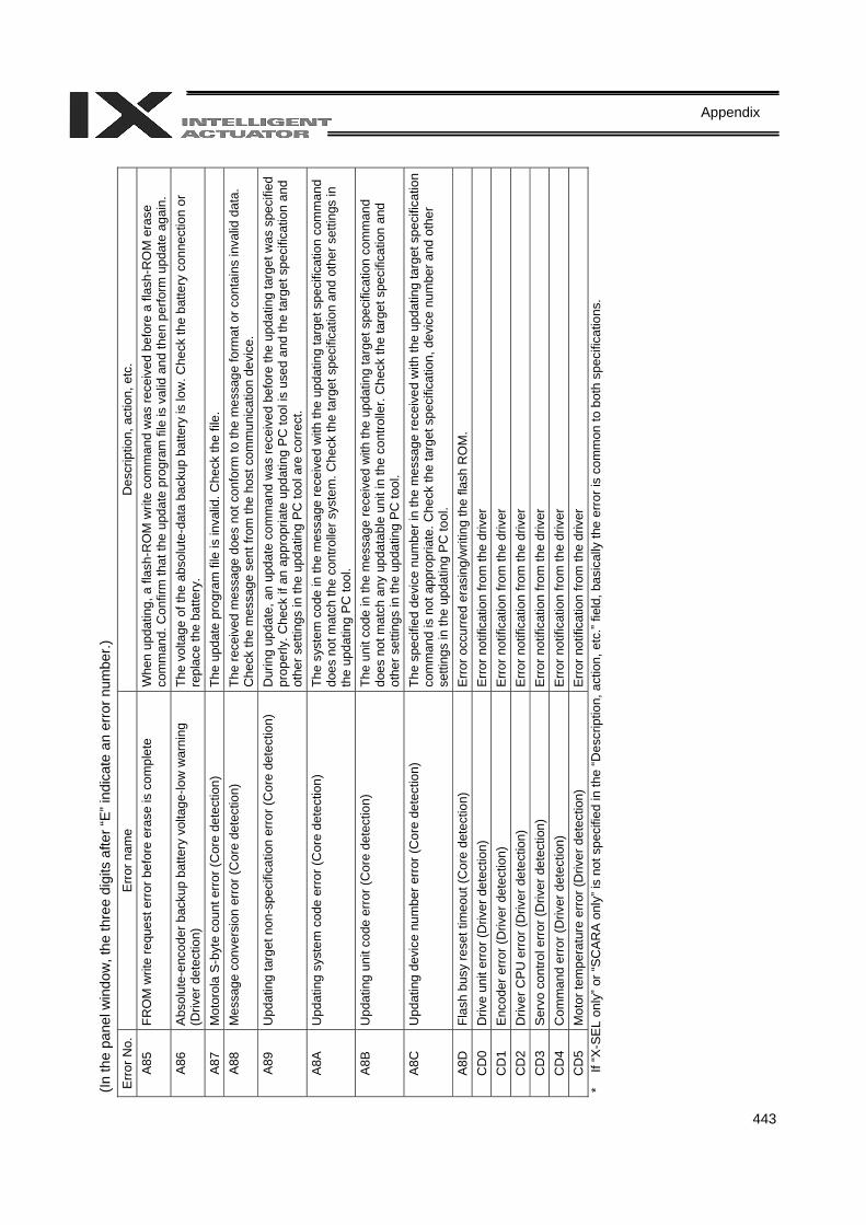
443
Appendix
(In th
e pa
nel w
indo
w, t
he th
ree
digi
ts a
fter “
E” in
dica
te a
n er
ror n
umbe
r.)
Erro
r No.
E
rror n
ame
Des
crip
tion,
act
ion,
etc
. A
85
FRO
M w
rite
requ
est e
rror
bef
ore
eras
e is
com
plet
e W
hen
upda
ting,
a fl
ash-
RO
M w
rite
com
man
d w
as re
ceiv
ed b
efor
e a
flash
-RO
M e
rase
co
mm
and.
Con
firm
that
the
upda
te p
rogr
am fi
le is
val
id a
nd th
en p
erfo
rm u
pdat
e ag
ain.
A
86
Abs
olut
e-en
code
r bac
kup
batte
ry v
olta
ge-lo
w w
arni
ng
(Driv
er d
etec
tion)
Th
e vo
ltage
of t
he a
bsol
ute-
data
bac
kup
batte
ry is
low
. Che
ck th
e ba
ttery
con
nect
ion
or
repl
ace
the
batte
ry.
A87
M
otor
ola
S-b
yte
coun
t err
or (C
ore
dete
ctio
n)
The
upda
te p
rogr
am fi
le is
inva
lid. C
heck
the
file.
A
88
Mes
sage
con
vers
ion
erro
r (C
ore
dete
ctio
n)
The
rece
ived
mes
sage
doe
s no
t con
form
to th
e m
essa
ge fo
rmat
or c
onta
ins
inva
lid d
ata.
C
heck
the
mes
sage
sen
t fro
m th
e ho
st c
omm
unic
atio
n de
vice
. A
89
Upd
atin
g ta
rget
non
-spe
cific
atio
n er
ror (
Cor
e de
tect
ion)
D
urin
g up
date
, an
upda
te c
omm
and
was
rece
ived
bef
ore
the
upda
ting
targ
et w
as s
peci
fied
prop
erly
. Che
ck if
an
appr
opria
te u
pdat
ing
PC
tool
is u
sed
and
the
targ
et s
peci
ficat
ion
and
othe
r set
tings
in th
e up
datin
g PC
tool
are
cor
rect
. A
8A
Upd
atin
g sy
stem
cod
e er
ror (
Cor
e de
tect
ion)
Th
e sy
stem
cod
e in
the
mes
sage
rece
ived
with
the
upda
ting
targ
et s
peci
ficat
ion
com
man
d do
es n
ot m
atch
the
cont
rolle
r sys
tem
. Che
ck th
e ta
rget
spe
cific
atio
n an
d ot
her s
ettin
gs in
th
e up
datin
g PC
tool
. A
8B
Upd
atin
g un
it co
de e
rror
(Cor
e de
tect
ion)
Th
e un
it co
de in
the
mes
sage
rece
ived
with
the
upda
ting
targ
et s
peci
ficat
ion
com
man
d do
es n
ot m
atch
any
upd
atab
le u
nit i
n th
e co
ntro
ller.
Che
ck th
e ta
rget
spe
cific
atio
n an
d ot
her s
ettin
gs in
the
upda
ting
PC to
ol.
A8C
U
pdat
ing
devi
ce n
umbe
r err
or (C
ore
dete
ctio
n)
The
spec
ified
dev
ice
num
ber i
n th
e m
essa
ge re
ceiv
ed w
ith th
e up
datin
g ta
rget
spe
cific
atio
n co
mm
and
is n
ot a
ppro
pria
te. C
heck
the
targ
et s
peci
ficat
ion,
dev
ice
num
ber a
nd o
ther
se
tting
s in
the
upda
ting
PC
tool
. A
8D
Flas
h bu
sy re
set t
imeo
ut (C
ore
dete
ctio
n)
Erro
r occ
urre
d er
asin
g/w
ritin
g th
e fla
sh R
OM
. C
D0
Driv
e un
it er
ror (
Driv
er d
etec
tion)
Er
ror n
otifi
catio
n fro
m th
e dr
iver
C
D1
Enc
oder
erro
r (D
river
det
ectio
n)
Erro
r not
ifica
tion
from
the
driv
er
CD
2 D
river
CP
U e
rror
(Driv
er d
etec
tion)
Er
ror n
otifi
catio
n fro
m th
e dr
iver
C
D3
Ser
vo c
ontro
l erro
r (D
river
det
ectio
n)
Erro
r not
ifica
tion
from
the
driv
er
CD
4 C
omm
and
erro
r (D
river
det
ectio
n)
Erro
r not
ifica
tion
from
the
driv
er
CD
5 M
otor
tem
pera
ture
erro
r (D
river
det
ectio
n)
Erro
r not
ifica
tion
from
the
driv
er
* If
“X-S
EL o
nly”
or “
SC
ARA
only
” is
not s
peci
fied
in th
e “D
escr
iptio
n, a
ctio
n, e
tc.”
field
, bas
ical
ly th
e er
ror i
s co
mm
on to
bot
h sp
ecifi
catio
ns.
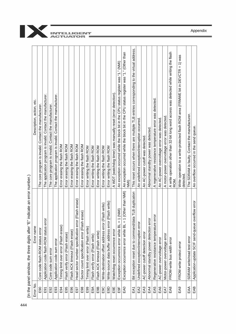
444
Appendix
(In th
e pa
nel w
indo
w, t
he th
ree
digi
ts a
fter “
E” in
dica
te a
n er
ror n
umbe
r.)
Erro
r No.
E
rror n
ame
Des
crip
tion,
act
ion,
etc
. E
90
Cor
e co
de fl
ash-
RO
M s
tatu
s er
ror
The
core
pro
gram
is in
valid
. Con
tact
the
man
ufac
ture
r. E
91
App
licat
ion
code
flas
h-R
OM
sta
tus
erro
r Th
e ap
plic
atio
n pr
ogra
m is
inva
lid. C
onta
ct th
e m
anuf
actu
rer.
E92
C
ore
code
sum
err
or
The
core
pro
gram
is in
valid
. Con
tact
the
man
ufac
ture
r. E
93
App
licat
ion
code
sum
erro
r Th
e ap
plic
atio
n pr
ogra
m is
inva
lid. C
onta
ct th
e m
anuf
actu
rer.
E94
Ti
min
g lim
it ov
er e
rror
(Fla
sh e
rase
) E
rror
era
sing
the
flash
RO
M
E95
Fl
ash
verif
y er
ror (
Flas
h er
ase)
E
rror
era
sing
the
flash
RO
M
E96
Fl
ash
AC
K ti
meo
ut (F
lash
era
se)
Err
or e
rasi
ng th
e fla
sh R
OM
E
97
Hea
d se
ctor
num
ber s
peci
ficat
ion
erro
r (Fl
ash
eras
e)
Err
or e
rasi
ng th
e fla
sh R
OM
E
98
Sec
tor c
ount
spe
cific
atio
n er
ror (
Flas
h er
ase)
E
rror
era
sing
the
flash
RO
M
E99
Ti
min
g lim
it ov
er e
rror
(Fla
sh w
rite)
E
rror w
ritin
g th
e fla
sh R
OM
E
9A
Flas
h ve
rify
erro
r (Fl
ash
writ
e)
Erro
r writ
ing
the
flash
RO
M
E9B
Fl
ash
AC
K ti
meo
ut (F
lash
writ
e)
Erro
r writ
ing
the
flash
RO
M
E9C
W
rite-
dest
inat
ion
offs
et a
ddre
ss e
rror
(Fla
sh w
rite)
Er
ror w
ritin
g th
e fla
sh R
OM
E
9D
Writ
e-so
urce
dat
a bu
ffer a
ddre
ss e
rror (
Flas
h w
rite)
E
rror w
ritin
g th
e fla
sh R
OM
E
9E
Wat
chdo
g re
set o
ccur
renc
e er
ror
A W
DT
(wat
chdo
g tim
er) w
as m
anua
lly re
set (
erro
r det
ectio
n).
E9F
E
xcep
tion
occu
rren
ce e
rror
whi
le B
L =
1 (N
MI)
An
exce
ptio
n oc
curr
ed w
hile
the
bloc
k bi
t in
the
CP
U s
tatu
s re
gist
er w
as “1
.” (N
MI)
EA0
E
xcep
tion
occu
rren
ce e
rror
whi
le B
L =
1 (O
ther
than
NM
I) A
n ex
cept
ion
occu
rred
whi
le th
e bl
ock
bit i
n th
e C
PU
sta
tus
regi
ster
was
“1.”
(Oth
er th
an
NM
I) E
A1
Bit
exce
ptio
n re
set d
ue to
com
man
d/da
ta T
LB d
uplic
atio
n Th
is re
set o
ccur
s w
hen
ther
e ar
e m
ultip
le T
LB e
ntrie
s co
rres
pond
ing
to th
e vi
rtual
add
ress
. E
A2
Und
efin
ed e
xcep
tion/
inte
rrupt
ion
erro
r A
n un
defin
ed e
xcep
tion/
inte
rrup
tion
occu
rred
. E
A3
AC
-pow
er c
utof
f det
ectio
n er
ror
An A
C-p
ower
cut
off w
as d
etec
ted.
E
A4
Abn
orm
al s
tand
by p
ower
det
ectio
n er
ror
Abn
orm
al s
tand
by p
ower
was
det
ecte
d.
EA5
R
egen
erat
ive
resi
stan
ce te
mpe
ratu
re e
rror
A
rege
nera
tive
resi
stan
ce te
mpe
ratu
re e
rror
was
det
ecte
d.
EA6
A
C-p
ower
ove
rvol
tage
err
or
An
AC
-pow
er o
verv
olta
ge e
rror
was
det
ecte
d.
EA7
M
otor
-pow
er o
verv
olta
ge e
rror
A
mot
or-p
ower
ove
rvol
tage
err
or w
as d
etec
ted.
E
A8
FRO
M-w
rite
bus
wid
th e
rror
A
writ
e op
erat
ion
othe
r tha
n 32
-bit
long
wor
d ac
cess
was
det
ecte
d w
hile
writ
ing
the
flash
R
OM
. E
A9
FRO
M w
rite
prot
ect e
rror
W
rite
oper
atio
n to
a w
rite-
prot
ecte
d fla
sh R
OM
are
a (F
RM
WE
bit
in D
EV
CTR
= 1
) was
de
tect
ed.
EA
A
SD
RA
M w
rite/
read
test
erro
r Th
e S
DR
AM
is fa
ulty
. Con
tact
the
man
ufac
ture
r. E
AB
A
pplic
atio
n-up
date
SC
IF s
end-
queu
e ov
erflo
w e
rror
An
over
flow
occ
urre
d in
the
send
que
ue.
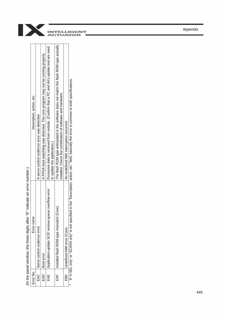
445
Appendix
(In th
e pa
nel w
indo
w, t
he th
ree
digi
ts a
fter “
E” in
dica
te a
n er
ror n
umbe
r.)
Erro
r No.
E
rror n
ame
Des
crip
tion,
act
ion,
etc
. E
AC
S
ervo
con
trol u
nder
run
erro
r A
ser
vo c
ontro
l und
erru
n er
ror w
as d
etec
ted.
E
AD
B
oot e
rror
A F
PG
A b
oot w
atch
dog
was
det
ecte
d. T
he c
ore
prog
ram
may
not
be
runn
ing
prop
erly
. E
AE
A
pplic
atio
n-up
date
SC
IF re
ceiv
e-qu
eue
over
flow
erro
r E
xces
sive
dat
a is
rece
ived
from
out
side
. (C
onfir
m th
at a
PC
and
IAI’s
upd
ate
tool
are
use
d to
upd
ate
the
appl
icat
ion.
) E
AF
Inst
alle
d fla
sh R
OM
type
mis
mat
ch (C
ore)
Th
e fla
sh R
OM
type
ant
icip
ated
in th
e so
ftwar
e do
es n
ot m
atch
the
flash
RO
M ty
pe a
ctua
lly
inst
alle
d. C
heck
the
com
bina
tion
of s
oftw
are
and
hard
war
e.
EB0
U
ndef
ined
NM
I err
or (C
ore)
A
n un
defin
ed N
MI i
nter
rupt
ion
occu
rred
. *
If “X
-SEL
onl
y” o
r “S
CAR
A on
ly” i
s no
t spe
cifie
d in
the
“Des
crip
tion,
act
ion,
etc
.” fie
ld, b
asic
ally
the
erro
r is
com
mon
to b
oth
spec
ifica
tions
.
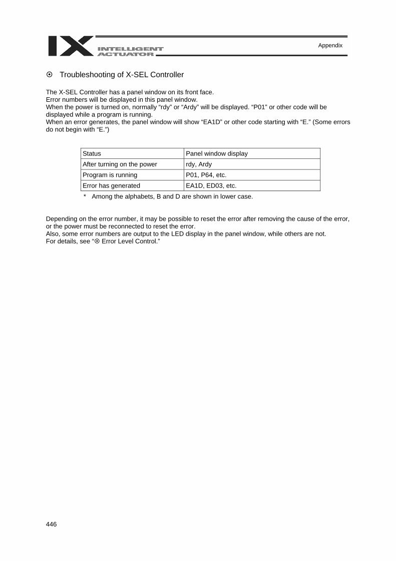
446
Appendix
Troubleshooting of X-SEL Controller
The X-SEL Controller has a panel window on its front face. Error numbers will be displayed in this panel window. When the power is turned on, normally “rdy” or “Ardy” will be displayed. “P01” or other code will be displayed while a program is running. When an error generates, the panel window will show “EA1D” or other code starting with “E.” (Some errors do not begin with “E.”)
Status Panel window display After turning on the power rdy, Ardy Program is running P01, P64, etc. Error has generated EA1D, ED03, etc. * Among the alphabets, B and D are shown in lower case.
Depending on the error number, it may be possible to reset the error after removing the cause of the error, or the power must be reconnected to reset the error. Also, some error numbers are output to the LED display in the panel window, while others are not. For details, see “ Error Level Control.”
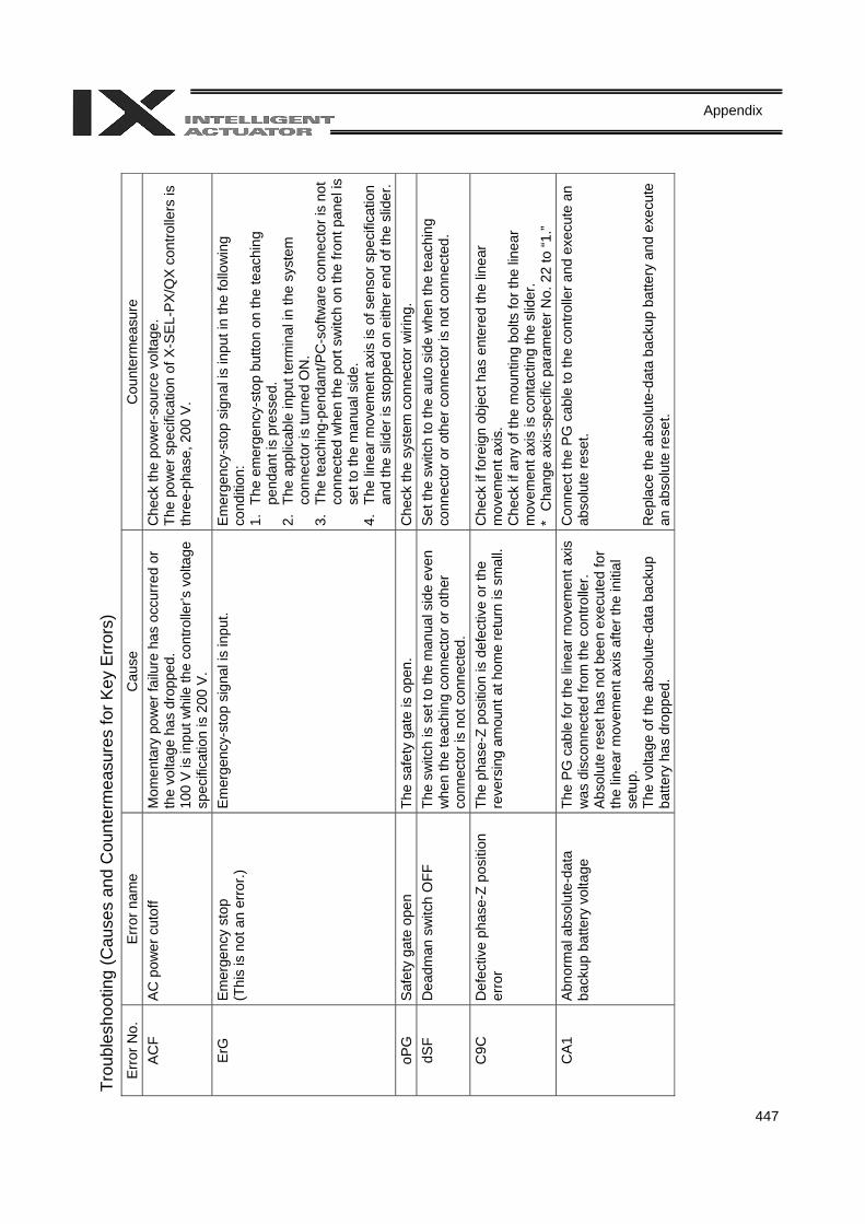
447
Appendix Tr
oubl
esho
otin
g (C
ause
s an
d C
ount
erm
easu
res
for K
ey E
rror
s)
Erro
r No.
Er
ror n
ame
Cau
se
Cou
nter
mea
sure
AC
F AC
pow
er c
utof
f M
omen
tary
pow
er fa
ilure
has
occ
urre
d or
th
e vo
ltage
has
dro
pped
. 10
0 V
is in
put w
hile
the
cont
rolle
r’s v
olta
ge
spec
ifica
tion
is 2
00 V
.
Che
ck th
e po
wer
-sou
rce
volta
ge.
The
pow
er s
peci
ficat
ion
of X
-SE
L-PX
/QX
cont
rolle
rs is
th
ree-
phas
e, 2
00 V
.
ErG
Em
erge
ncy
stop
(T
his
is n
ot a
n er
ror.)
Em
erge
ncy-
stop
sig
nal i
s in
put.
Emer
genc
y-st
op s
igna
l is
inpu
t in
the
follo
win
g co
nditi
on:
1. T
he e
mer
genc
y-st
op b
utto
n on
the
teac
hing
pe
ndan
t is
pres
sed.
2.
The
app
licab
le in
put t
erm
inal
in th
e sy
stem
co
nnec
tor i
s tu
rned
ON
. 3.
The
teac
hing
-pen
dant
/PC
-sof
twar
e co
nnec
tor i
s no
t co
nnec
ted
whe
n th
e po
rt sw
itch
on th
e fro
nt p
anel
is
set t
o th
e m
anua
l sid
e.
4. T
he li
near
mov
emen
t axi
s is
of s
enso
r spe
cific
atio
n an
d th
e sl
ider
is s
topp
ed o
n ei
ther
end
of t
he s
lider
. oP
G
Safe
ty g
ate
open
Th
e sa
fety
gat
e is
ope
n.
Che
ck th
e sy
stem
con
nect
or w
iring
. dS
F D
eadm
an s
witc
h O
FF
The
switc
h is
set
to th
e m
anua
l sid
e ev
en
whe
n th
e te
achi
ng c
onne
ctor
or o
ther
co
nnec
tor i
s no
t con
nect
ed.
Set t
he s
witc
h to
the
auto
sid
e w
hen
the
teac
hing
co
nnec
tor o
r oth
er c
onne
ctor
is n
ot c
onne
cted
.
C9C
D
efec
tive
phas
e-Z
posi
tion
erro
r Th
e ph
ase-
Z po
sitio
n is
def
ectiv
e or
the
reve
rsin
g am
ount
at h
ome
retu
rn is
sm
all.
Che
ck if
fore
ign
obje
ct h
as e
nter
ed th
e lin
ear
mov
emen
t axi
s.
Che
ck if
any
of t
he m
ount
ing
bolts
for t
he li
near
m
ovem
ent a
xis
is c
onta
ctin
g th
e sl
ider
. *
Cha
nge
axis
-spe
cific
par
amet
er N
o. 2
2 to
“1.”
CA1
Ab
norm
al a
bsol
ute-
data
ba
ckup
bat
tery
vol
tage
Th
e PG
cab
le fo
r the
line
ar m
ovem
ent a
xis
was
dis
conn
ecte
d fro
m th
e co
ntro
ller.
Abso
lute
rese
t has
not
bee
n ex
ecut
ed fo
r th
e lin
ear m
ovem
ent a
xis
afte
r the
initi
al
setu
p.
The
volta
ge o
f the
abs
olut
e-da
ta b
acku
p ba
ttery
has
dro
pped
.
Con
nect
the
PG c
able
to th
e co
ntro
ller a
nd e
xecu
te a
n ab
solu
te re
set.
Rep
lace
the
abso
lute
-dat
a ba
ckup
bat
tery
and
exe
cute
an
abs
olut
e re
set.
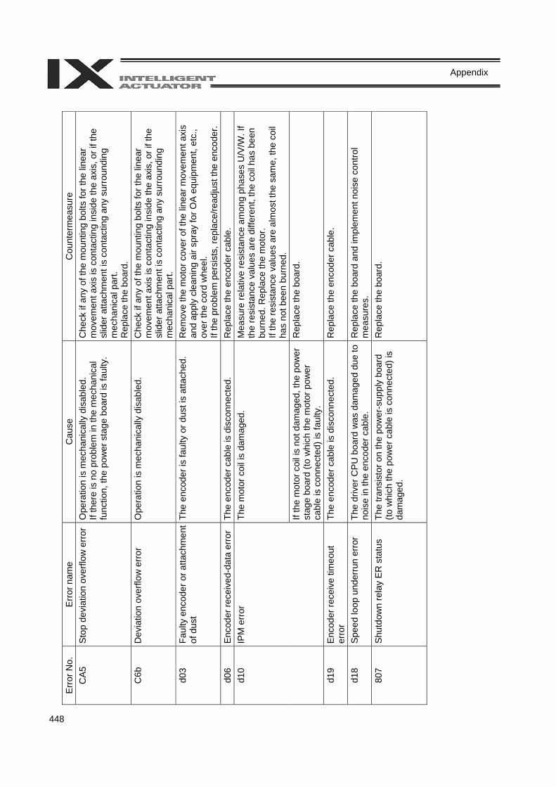
448
Appendix
Er
ror N
o.
Erro
r nam
e C
ause
C
ount
erm
easu
re
CA5
St
op d
evia
tion
over
flow
erro
r O
pera
tion
is m
echa
nica
lly d
isab
led.
If
ther
e is
no
prob
lem
in th
e m
echa
nica
l fu
nctio
n, th
e po
wer
sta
ge b
oard
is fa
ulty
.
Che
ck if
any
of t
he m
ount
ing
bolts
for t
he li
near
m
ovem
ent a
xis
is c
onta
ctin
g in
side
the
axis
, or i
f the
sl
ider
atta
chm
ent i
s co
ntac
ting
any
surro
undi
ng
mec
hani
cal p
art.
Rep
lace
the
boar
d.
C6b
D
evia
tion
over
flow
err
or
Ope
ratio
n is
mec
hani
cally
dis
able
d.
Che
ck if
any
of t
he m
ount
ing
bolts
for t
he li
near
m
ovem
ent a
xis
is c
onta
ctin
g in
side
the
axis
, or i
f the
sl
ider
atta
chm
ent i
s co
ntac
ting
any
surro
undi
ng
mec
hani
cal p
art.
d03
Faul
ty e
ncod
er o
r atta
chm
ent
of d
ust
The
enco
der i
s fa
ulty
or d
ust i
s at
tach
ed.
Rem
ove
the
mot
or c
over
of t
he li
near
mov
emen
t axi
s an
d ap
ply
clea
ning
air
spra
y fo
r OA
equi
pmen
t, et
c.,
over
the
cord
whe
el.
If th
e pr
oble
m p
ersi
sts,
repl
ace/
read
just
the
enco
der.
d06
Enco
der r
ecei
ved-
data
erro
r Th
e en
code
r cab
le is
dis
conn
ecte
d.
Rep
lace
the
enco
der c
able
. Th
e m
otor
coi
l is
dam
aged
. M
easu
re re
lativ
e re
sist
ance
am
ong
phas
es U
/V/W
. If
the
resi
stan
ce v
alue
s ar
e di
ffere
nt, t
he c
oil h
as b
een
burn
ed. R
epla
ce th
e m
otor
. If
the
resi
stan
ce v
alue
s ar
e al
mos
t the
sam
e, th
e co
il ha
s no
t bee
n bu
rned
.
d10
IPM
err
or
If th
e m
otor
coi
l is
not d
amag
ed, t
he p
ower
st
age
boar
d (to
whi
ch th
e m
otor
pow
er
cabl
e is
con
nect
ed) i
s fa
ulty
.
Rep
lace
the
boar
d.
d19
Enco
der r
ecei
ve ti
meo
ut
erro
r Th
e en
code
r cab
le is
dis
conn
ecte
d.
Rep
lace
the
enco
der c
able
.
d18
Spee
d lo
op u
nder
run
erro
r Th
e dr
iver
CPU
boa
rd w
as d
amag
ed d
ue to
no
ise
in th
e en
code
r cab
le.
Rep
lace
the
boar
d an
d im
plem
ent n
oise
con
trol
mea
sure
s.
807
Shut
dow
n re
lay
ER s
tatu
s Th
e tra
nsis
tor o
n th
e po
wer
-sup
ply
boar
d (to
whi
ch th
e po
wer
cab
le is
con
nect
ed) i
s da
mag
ed.
Rep
lace
the
boar
d.

449
Appendix
Trouble Report Sheet
Trouble Report Sheet Date: Company name Department Reported by
TEL (Ext) FAX IAI agent Purchase date
Serial number Manufacture date
[1] Number of axes axis(es)
Type
[2] Type of problem 1. Disabled operation 2. Position deviation 3. Runaway machine 4. Error Error code = 5. Other ( )
[3] Problem frequency and condition Frequency = Condition
[4] When did the problem occur? 1. Right after the system was set up 2. After operating for a while (Operating hours: year(s) and month(s))
[5] Operating direction 1. SCARA only 2. SCARA + Linear movement axis
[6] Load condition 1. Load transfer 2. Push-motion operation 3. Load: Approx. kg 4. Speed: Approx. mm/sec
[7] Special specification (option, etc.)

X-SEL-PX/QX Controller, Manual No. 0107-E, Version MJ0152-1A-E (Dec. 2006)
IAI Industrieroboter GmbHOber der Röth 4, D-65824 Schwalbach am Taunus
GermanyTel.:+49-6196-8895-0Fax: 06196-889524-24
E-Mail: [email protected]: http://www.eu.IAI-GmbH.de
IAI America Inc.2690 W. 237th Street, Torrance, CA 90505, USATel.: +1-310-891-6015 Fax: +1-310-891-0815
IAI CORPORATION645-1 Shimizu Hirose, Shizuoka 424-0102, JapanTel.: +81-543-64-5105 Fax: +81-543-64-5182
The information contained in this document is subject to change without notice for the purpose of product improvement.Copyright © 2005 IAI Corporation. All rights reserved.