X-ray Topography system based on Lang method XRT-100 ...
52
X-ray Topography system based on Lang method XRT-100 Operating Manual Manual No. ME14903B01 Rigaku Corporation
Transcript of X-ray Topography system based on Lang method XRT-100 ...

X-ray Topography system based on Lang method
XRT-100
Operating Manual
Manual No. ME14903B01
Rigaku Corporation

ME14903B - i
Contents
2. Concept of X-ray diffraction topography and possible experimental setup ........................................3 2.1 Lang method ......................................................................................................................................4 2.2 Step scanning section topography......................................................................................................4 2.3 Surface reflection topography............................................................................................................5
3. Specifications..............................................................................................................................................6 3.1 X-ray generator ..................................................................................................................................6 3.2 Four-inch Lang camera......................................................................................................................6 3.3 Controller and software .....................................................................................................................7 3.4 X-ray Vision Camera .........................................................................................................................8 3.5 Mount and radiation enclosure...........................................................................................................8
4. Installation conditions ...............................................................................................................................9 4.1 Ambient environment ........................................................................................................................9 4.2 Power supply .....................................................................................................................................9
5. Structure and Functions .........................................................................................................................10 5.1 Incident optics..................................................................................................................................11 5.2 Topographic goniometer (topogonio) ..............................................................................................12 5.3 Sample holder ..................................................................................................................................14 5.4 Positioning the film cassette bracket and film cassette....................................................................16 5.5 Receiving optics...............................................................................................................................17 5.6 X-ray Vision Camera .......................................................................................................................18 5.7 Controller and motor-driven axes ....................................................................................................19
6. Operation .................................................................................................................................................20 6.1 Starting up and shutting down the system .......................................................................................20 6.2 Lang method ....................................................................................................................................21
6.2.1 Principle of Lang method......................................................................................................21 6.2.2 Principles of forming lattice defect images...........................................................................22 6.2.3 Spatial resolution...................................................................................................................25 6.2.4 Procedures.............................................................................................................................26 6.2.5 Simultaneous reflection image..............................................................................................31 6.2.6 Scattered X-ray shielding plate for transmission topography ...............................................33
6.3 Section topography ..........................................................................................................................34 6.3.1 Principles of section topography...........................................................................................34 6.3.2 Tools for section topography ................................................................................................35 6.3.3 Procedures for section topography........................................................................................35
6.4 Surface reflection topography..........................................................................................................37 6.4.1 Principles of surface reflection topography ..........................................................................37 6.4.2 Procedures for surface reflection topography .......................................................................39 6.4.3 Scattered X-ray shielding plate for reflection topography ....................................................42
6.5 Darkroom equipment .......................................................................................................................43

ME14903B - ii
6.5.1 X-ray film and nuclear plates ................................................................................................43 6.5.2 Developer ..............................................................................................................................43 6.5.3 Darkroom equipment ............................................................................................................43
7. Maintenance.............................................................................................................................................45 7.1 Replacing the mylar films on the sample holder rings ....................................................................45 7.2 Installation .......................................................................................................................................46
Appendix .........................................................................................................................................................47 A Data ............................................................................................................................................47 B Guide for references related to topography ................................................................................49
First Edition: January 6, 2010

- 1 - ME14903B
1. Outline
Technological improvements in the electronics industry have made it possible to produce a variety of large single crystals, and such crystals are now being used in semiconductors and other devices. This unit is an X-ray diffraction topography system that enables you to nondestructively observe lattice defects such as dislocations, impurity segregation/precipitation, and stacking fault in such large crystals.
The basic features of this system are as follows:
(1) It allows large samples (up to 4" wafers) to be studied;
(2) There is no contamination of the sample by virtue of the Mylar-foil sample sandwich method;
(3) There is no fear of X-ray exposure, as crystal alignment can be done with a remote ω-angle and in-plane rotation mechanism;
(4) Alignment is easy with the X-ray Vision Camera and the vertically movable mechanism of the X-ray detector; and
(5) Normal focus is available as an X-ray source.

- 2 - ME14903B
Fig.1(a) Overview of XRT-100 system
Fig.1(b) XRT-100 main body

- 3 - ME14903B
2. Concept of X-ray diffraction topography and possible experimental setup
X-ray topography is a measurement technique whereby lattice defects and strain in a single crystal are observed as an X-ray diffraction image. The acquired X-ray diffraction image is called an X-ray topograph. As is widely known, the sample crystal diffracts the incident X-ray beam when the crystal is positioned so that lattice planes with lattice spacing d satisfy the Bragg condition, 2dsinθB = λ, with respect to wavelength λ of the incident X-rays. If the X-ray radiation field ABCD includes structural defects as shown in Fig. 2.1, the diffracted X-ray intensities differ between beams from areas containing defects and from areas free of defects. The difference is recorded on X-ray film or other media to produce an X-ray image corresponding in point to point fashion with the crystal. This image is the X-ray topograph.
Sample crystal
Lattice spacing d
2d sin θB = λ B
A Diffraction line
Crystal defect
θB D
C
Incident X-ray wave length: λ Photo plate
Fig.2.1 Consept of X-ray topography
The following subsections describe the topography techniques supported by the XRT-100 system.

- 4 - ME14903B
2.1 Lang method
Lang method uses a Mo target and performs topography in transmission geometry. This method is capable of capturing an image of defect distributions throughout the wafer and can be applied for wafer quality inspections. Topography with a fine focus produces high spatial resolution.
Diffraction slit
Nuclear plate / Film /IP Sample crystal
Incident slit X-ray source
X-ray detector
Scan
Fig. 2.2 Lang method
2.2 Step scanning section topography
Step scanning section topography uses a Mo target and performs topography in transmission geometry with a 10-µm slit placed near the sample, the sample, and the nuclear plate fixed for time exposures. This method provides information on defect distributions in the axis of thickness of the sample. The stage can be moved stepwise to make multiple exposures.
Sample crystal 10μm width narrow slit
Nuclear plate
X-ray source
Extended slit holder X-ray detector
Step move
Fig. 2.3 Step scanning section topography

- 5 - ME14903B
2.3 Surface reflection topography
Surface reflection topography uses a Cu target and performs topography in reflection geometry. This method is capable of imaging the entire wafer and can be used for crystal quality inspections. It provides information on surface defects.
Scan
Sample crystal X-ray source
X-ray film / IP
Fig. 2.4 Surface reflection topography

- 6 - ME14903B
3. Specifications
3.1 X-ray generator
(1) Maximum rated output: 3 kW
(2) Rated tube voltage: 20 kV to 60 kV (1-kV step)
(3) Rated tube current: 2 mA to 50 mA (1-mA step)
(4) Stability (tube voltage and tube current): ±0.01% or less (power supply fluctuations should be ±10% or less.)
(5) Tube shield: Horizontal
(6) X-ray window: Equipped with electromagnetic shutter
(7) Target (selected): Mo(for transmission topography) and Cu(for reflection topography) selected
(8) Safety device: Cooling water error (water quantity, water pressure, water temperature)
XG overload fault (overload, line current, filament current)
Tube voltage HIGH/LOW fault
Filament burnout detection
Emergency stop switch
Ground-fault circuit breaker
(9) Water circulation pump: Water circulation pump for 3-kW equipment. Temperature control: ±0.5°C
3.2 Four-inch Lang camera
(1) Distance between X-ray source and sample:1,100 mm
(2) Center height of X-ray beam above mount:490 mm
(3) 2θ rotation plate Set range: 0° to 115°, can be set manually. Read with degree scale
(4) ω rotation plate
Coarse adjustment: 0° to 150° can be set manually. Read with degree scale
Fine adjustment: Pulse motor operable within the range of ±3.5°. Resolution: 0.0001 deg/step
(5) Sample holder: Usable both transmission and reflection topography φ rotation : In-plane rotation of 360° for both transmission and
reflection topography. Pulse motor-driven.
Holder: The sample is inserted between mylar sheets.
Tilting: ±5°, manual setting.
(6) Scanning stage: Scanning range of ±52 mm. Pulse motor-driven.

- 7 - ME14903B
(7) X-ray detector holder: Fixed on the 2θ rotation plate. The vertical positions of the X-ray detectors can be set by manual in a range of ±50 mm from the height of the X-ray beam center.
(8) First slit: 3 mm width. Fixed slit in the cylinder pipe.
(9) Second slit
(i) Width-limiting slit : Straight slits with widths of 0.1 mm, 0.2 mm, 0.5 mm,
1 mm, 1.5 mm, and 2 mm
(ii) Height-limiting slit: 25 mm, 50 mm, and 75 mm
(iii) Slit for section topography: Equipped with an extension slit holder to reduce the
distance between the slit and the sample. Slit widths of
0.01 mm (for topography), 0.2 mm and 1 mm (for
setting). Slit height of 20 mm.
(iv) Slit for zero setting: 0.2 mm
(10) Third slit: Width from 0.5 mm to 16 mm. Pulse motor-driven.
(11) Film cassette: 4.5-inch square film cassette. 1-inch ×1.5-inch nuclear plate cassette. Two sets are supplied.
(12) Connection fitting: Connection fitting between the Lang camera and the X-ray tube shutter.
3.3 Controller and software
(1) Control motor axes: Five axes, including ω fine adjustment, φ, scanning stage, third slit (right and left).
(2) Curve correction: The scanning stage and the ω fine adjustment are moved
together for curve corrections. The minimum curve correction radius is 5 m.
(3) Communication method: RS232C
(4) Topography control software: •Axis setup
•Traverse topography measurement
•Curve correction data measurement
•Section topography measurement
(5) Personal computer section: •HP desktop PC, d530 •Pentium 4 2.8 GHz •512 MB Memory •80 GB HDD •48× CD-RW •OS Windows 2000 •17-inch TFT Monitor •Color printer

- 8 - ME14903B
3.4 X-ray Vision Camera
The X-ray Vision Camera mounted on the counter holder is used for sample axial adjustments and optical adjustments. X-ray images are transferred to the PC through a video capture board and viewed on the PC CRT monitor.
(1) Configuration
• X-ray image intensifier
• CCD video camera
• Video capture board
(2) Sensitive area: Approximate diameter of 40 mm
(3) Luminance gain: 12,000
(4) Resolution limit: 100 µm
(5) CCD: 2/3-inch
3.5 Mount and radiation enclosure
(1) Mount dimensions: 1,000 mm W × 1,000 mm D × 720 mm H
(2) Radiation enclosure dimensions: 1,400 mm W × 1,425 mm D × 2,000 mm
(3) Radiation enclosure system: Iron plate radiation enclosure. Equipped with doors at the front and rear. Equipped with a lead plate measuring 3-mm in thickness (along the axis of the direct beam).
(4) Leakage X-ray: 2.0 µSv or less
(5) Warning lamp: Mounted on the top of the enclosure

- 9 - ME14903B
4. Installation conditions
4.1 Ambient environment
(1) Temperature: Within the range from 15°C to 25°C.
(2) Temperature fluctuation: Within the range of ±0.5°C or less during measurement. To ensure thermal stability of mechanical components, including the goniometer, temperature fluctuations should be kept as low as possible, even when no measurement is taking place.
(3) Vibration: No perceptible vibrations.
4.2 Power supply
(1) X-ray generator: Three-phase 200 VAC, 20 A
(2) Controller and personal computer section:Single-phase 100 VAC, 15 A
(3) X-ray Vision Camera: Branched from the power supply (3)
(4) Air-cooled water circulation pump: Three-phase 200 VAC, 15 A
(5) Grounding: Two series of Class-D grounding (One is used solely for
the computer)
Fig. 4.1 Configuration of XRT-100 system

- 10 - ME14903B
5. Structure and Functions
Fig. 5.1 provides a view of the entire XRT-100CCM system.
The equipment consists of the following five sections:
(1) 3kW X-ray generator
(2) Main unit
(3) Controller and Control PC
(4) X-ray vision camera
The X-ray generator and the main unit are each covered by a radiation enclosure. The main unit consists of the incident optics, topographic goniometer (topogoniometer), and the receiving optics.
The X-ray source is placed on the X-ray generator work table. The X-ray beam emitted from the X-ray source passes through the slit system to form a parallel beam and is directed to the sample attached to the topographic goniometer (topogoniometer). The diffracted X-rays are detected by the receiving optics, including the X-ray vision camera. The system can be controlled from the control PC.
The X-ray vision camera
Control PC
Main unit The controller is stored under the mount table.
X-ray generator,3 kW
Fig. 5.1 View of entire XRT-100CCM system

- 11 - ME14903B
5.1 Incident optics
(1) X-ray pass and first slit Set the Lang camera at a glancing angle of about 6° relative to the target face, then couple the X-ray pass with the X-ray window through the protector (Fig.5.2). The X-ray pass is a shield cylinder. Turn the shield cylinder so that the clamp dial of the protector directs upward. The first slit is fixed in the shield cylinder. The slit width is 3 mm. The purpose of the first slit is to keep excessive X-ray radiation from reaching the camera.
X-ray pass
the protector
Fig. 5.2 X-ray pass and connecting section
(2) Second slit, S2 The second slit is used to restrict the radiation field of the X-ray beam incident on the crystal. Use a width-limiting slit and a height-limiting slit based on the size of the crystal. Insert the slits into the slit box. Besides these slits, slits for section topography and a setting slit are provided.
Width-limiting slit
Height-limiting slit
Slit box
Fig. 5.3 Second slit section
D050214A05The first slit is fixed inthe shield cylinder.

- 12 - ME14903B
Setting slit
D
(a) Straight slits for transmission to
Fig.
Fig. 5.5 Slits
5.2 Topographic goniometer (topogonio
(1) 2θ rotation plate The 2θ rotation plate is a rotation mecrotates around the topogonio center anSet the angle with the scale plate and th
(2) ω rotation plate The ω rotation plate holds the scanntopogonio center. The plate is a rotatiobeam with respect to the sample crysMake coarse settings for the desired anTighten the clamp screw to enable fineof the ω vernier scale corresponds to a
(3) Scanning stage The scanning stage is a precision slidcrystal and the film and slides back anof motion is ±52 mm. If you try to m(limiter) will activate and halt moveme
D050214A06
pography Height-limiting slits
5.4 2nd Slits
for section topography
)
hanism that holds the X-ray detectors and thd sets the detectors and the slit to the diffractie reference line.
ing stage and the sample holder and rotaten mechanism for adjusting the incident angletal. Loosen the clamp screw to rotate the plgular position with the scale plate and the refe adjustment by the tangent bar method. A sin
n angle of 0.01°.
ing stage for acquiring wide-area topographsd forth along an axis parallel to the crystal plove the stage beyond this limit, an over-runnt.
050214A08
D050214A09
e third slit. It on angle (2θ).
s around the of the X-ray
ate manually. rence line. gle increment
. It holds the ane. Its range microswitch

- 13 - ME14903B
Third slit Sample holder
Second slit X-ray Vision camera
Scanning stage
ω rotation plate
Scale plate
Fig. 5.6 Topographic
ω clamp
2θ clamp
2θrotation plate
goniometer (topogoniometer)

- 14 - ME14903B
5.3 Sample holder
Fig. 5.9 is a photograph of the sample holder section. The sample holder is intended to hold a wafer or slab sample measuring less than 1 mm thick. The sample holder employed the Mylar-foil sample sandwich method.
The sample can be held between the Mylar-foil that is extended on a pair of holder rings (Fig.5.7). The holder rings can be used for both transmission and reflection topography.
Fig. 5.7 Sample holder ring
Set the crystal into the holder rings as described below.
(a) Place the crystal wafer in the center of Ring A (Fig. 5.8 (a) ). Crystal thickness must be less than 1 mm.
(b) Place Ring B (Fig. 5.8 (b) ) over Ring A and press. The crystal is held in place by the spring effect.
(c) Insert Rings A and B (Fig. 5.8 (c) )into the sample holder. Insert them until they stop; at this position, the crystal plane will match the rotation axis of the goniometer. The spring effect holds the crystal at an arbitrary in-plane rotational position.
(d) Fig. 5.81 (c) indicates the relationship between the X-ray incidence from the front and rear of the crystal.
The sample holder has a mechanism for adjusting the crystal orientation, permitting both in-plane rotation and tilting.

- 15 - ME14903B
Mylar
Wafer
Ring A
Mylar
Ring B
Ring A
Reflection method
Mylar
Rings A and B Crystal
Transmission method
Fig. 5.8 Sample holder rings
Fig. 5.9 Sample holder with holder rings inserted
- 16 - ME14903B
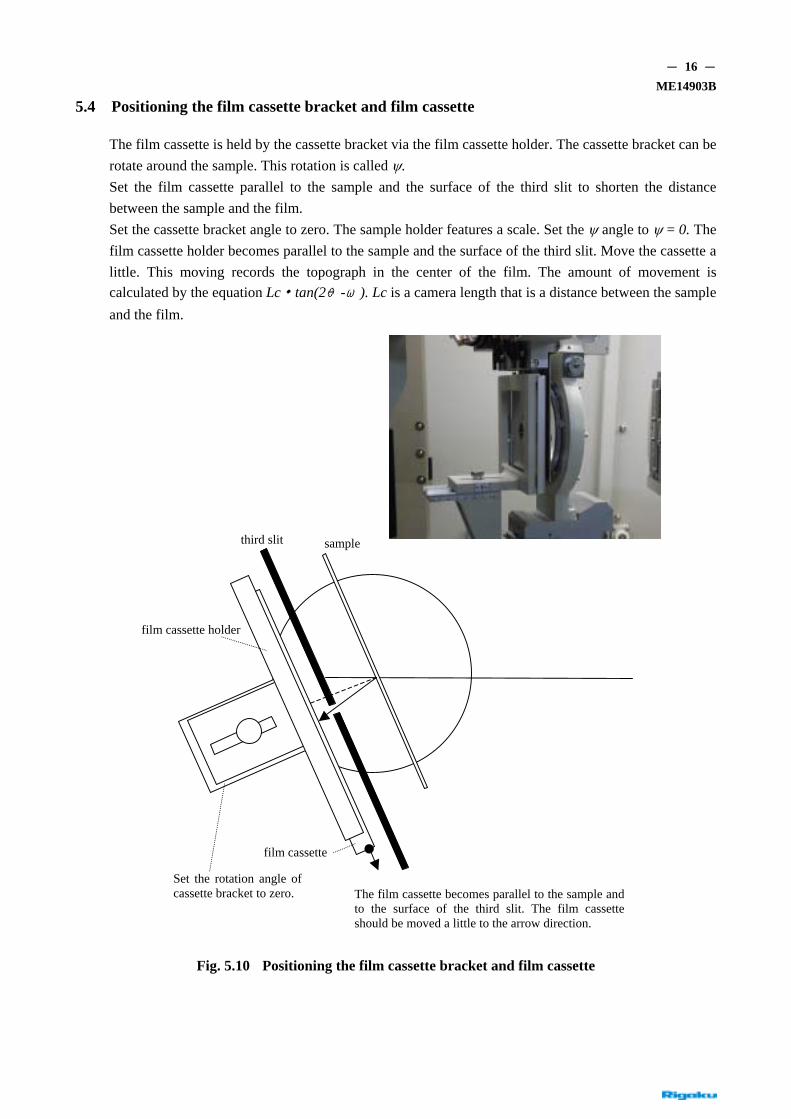
5.4 Positioning the film cassette bracket and film cassette
The film cassette is held by the cassette bracket via the film cassette holder. The cassette bracket can be rotate around the sample. This rotation is called ψ. Set the film cassette parallel to the sample and the surface of the third slit to shorten the distance between the sample and the film. Set the cassette bracket angle to zero. The sample holder features a scale. Set the ψ angle to ψ = 0. The film cassette holder becomes parallel to the sample and the surface of the third slit. Move the cassette a little. This moving records the topograph in the center of the film. The amount of movement is calculated by the equation Lc・tan(2θ-ω). Lc is a camera length that is a distance between the sample and the film.
third slit
film cassette holder
sample
film cassette
Set the rotation angle ofcassette bracket to zero. The film cassette becomes parallel to the sample and
to the surface of the third slit. The film cassetteshould be moved a little to the arrow direction.
Fig. 5.10 Positioning the film cassette bracket and film cassette

- 17 - ME14903B
5.5 Receiving optics
(1) Third slit (variable slit) (Fig. 5.11) The third slit is used to reduce the effects of beam scattering on the film and to provide protection against direct exposure to X-ray beams. The width of the slit is independently variable, driven by a pulse motor. The entire slit can be set rotated from the position perpendicular to the diffracted beam within the range of approximately ±30°. This mechanism makes it possible to set the scanning direction of the scanning stage parallel to the surface of the third slit and to reduce the distance between the sample and the film cassette. The film cassette and width of the third slit will be large when the Lang camera is used with a large sample; this means the resulting distance between the sample and the film is large, frequently resulting in poor resolution. The rotational setting of the third slit may help remedy this shortcoming.
Fig. 5.11 Third slit
(2) X-ray detector and movement mechanism We used the X-ray vision camera as an X-ray detector. You can move the sensitive area of the X-ray vision camera and set vertically to maximize the sensitive area. This is a convenient way to make axial adjustments of the large crystal in topography geometry.
X-ray Vision Camera
Knob for vertical movementof X-ray detector
Fig. 5.12 X-ray detector and movement mechanism

- 18 - ME14903B
5.6 X-ray Vision Camera
The X-ray Vision Camera is a highly sensitive X-ray TV that converts a faint X-ray diffraction image into visible light on a fluorescent screen, amplifies the image with the image intensifier (I.I.), and captures the output image with the lens-coupled CCD. The CCD operates at the TV rate. The output signal can be observed on the video monitor. Operate the topographic goniometer remotely while observing the video monitor and use the camera to search for diffraction lines and to perform axial adjustments of the crystal and other adjustments. Operate the X-ray Vision Camera as follows: Turn on controller power. Set the Gain control to zero. High voltage is supplied to the I.I. only after this step. Turn the Gain control clockwise to increase sensitivity. For standard use, set the Gain to 5 on the scale. Adjust the value according to X-ray intensity.
POWER GAIN
D050214A20 D050214A19
(a) X-ray Vision Camera main unit (b) Controller Fig. 5.13 X-ray Vision Camera
Video capture board Controller
Lens Fluorescent screen
CCD I.I
High voltage power supply
Fig. 5.14 Block diagram of X-ray Vision Camera

- 19 - ME14903B
5.7 Controller and motor-driven axes
The XRT-100 system uses the RCD3, Rigaku’s standard controller. The following five axes are motor-driven: ω, stage, φ, variable slit left and variable slit right. Fig. 5.20 schematically illustrates the arrangement of the motor-driven axes with respect to the incident X-ray direction when the 2θ and ω axes are set to zero. The arrows indicate the positive direction of translation or rotation. Table 5.1 shows the range of movement and resolution of the axes.
φ rotation
Stage
Slit left
ω Slit right
Direction of incident X-ray
Fig. 5.15 Configuration of motor-driven axes and positive direction of translation and rotation (indicated by arrows)
Table 5.1 List of motor-driven axes
Name of axis Range of movement Resolution
ω axis ±3.5° 0.0001°
Stage ±52 mm 0.001 mm
φ axis ±360° 0.005°
Variable slit left -5~+8 mm 0.00005 mm
Variable slit right -5~+8 mm 0.00005 mm

- 20 - ME14903B
6. Operation
This chapter describes the procedures for operating the XRT-100 system, starting with procedures related to daily startup and shutdown. The various topographic imaging techniques are described thereafter.
For discussions of general equipment handling, refer to the Lang Camera for Large Samples XRT-100 software Instruction Manual (ME14902E01).
6.1 Starting up and shutting down the system
Start up the system as follows:
(1) Provide power to the system. Turn on the breakers for the water circulation pump (three-phase, 200 V), X-ray generator (three-phase, 200 V), and the personal computer and controller (single-phase, 100 V).
(2) Turn on power for the TV camera system. Set the Gain of the X-ray Vision Camera controller to zero, then to around 5 on the scale.
(3) Start the PC and PC peripheral devices. (Power on in the following order: printer, monitor, PC.) Launch the topography control software, and begin initialization.
(5) Power on the X-ray generator. The water circulation pump will begin operating, and the system will move to the Ready state. (The doors of the radiation enclosure must be closed for Ready state.)
(7) Turn on X-ray generation. Warm up the equipment for approximately 5 minutes at minimum load.
(8) Gradually increase the X-ray load voltage (kV) and current (mA) manually. Take time to set the load to the value desired for measurement.
(9) For operations, launch the topography control software. Shut down the system as follows (generally speaking, shutdown procedures are simply the startup procedures reversed):
(1) Decrease the X-ray load, starting with current (mA), to the minimum load of 20 kV and 2 mA.
(2) Turn off X-ray generation. Allow the system to stand for approximately 3 minutes until the cooling water has automatically stopped.
(3) Turn off power for the X-ray generator.
(4) Close the topography control software and turn off power for the PC and peripheral devices.
(5) Turn off the power switch for the TV camera system.
(6) Turn off the 100-V power supply, then turn off power for the X-ray generator and the water circulation pump.

- 21 - ME14903B
6.2 Lang method
6.2.1 Principle of Lang method
Lang method, the topography method currently in widest use, was developed by A.R. Lang. Fig. 6.1 illustrates the underlying principles. The X-rays emitted from a point X-ray source are directed and width-limited by a long second slit and allowed to strike the sample, irradiating the sample crystal along a narrow strip. When the in-plane orientation and the incident angle are adjusted to satisfy the diffraction conditions for the lattice plane of the crystal, diffraction occurs across the entire area irradiated.
An X-ray tube with an Ag, Mo, or Cu cathode is generally used as the X-ray source.
Third slit
Sample Second slit
X-ray source Film
Detector
Scan
(a)
X-ray source
K α1
K α2
K β
Intensity
Wavelength
Second slit Sample Third slit Scan
Film
(c) X-ray wavelength distribution (b) Rough sketch of Lang’s method
Fig. 6.1 Principle of Lang’s method
The third slit has a function that reduces the background generated by the scattered X-rays. Narrow the width of the slit so that it shields the direct X-ray beam through the sample and allows only the diffracted X-ray beam to pass.
Scan the sample crystal parallel to the sample surface together with the film in the above configuration to obtain a diffraction image over the entire sample.

- 22 - ME14903B
When capturing a topograph, place the film as close to the sample as possible to produce a high-resolution image. A topograph acquired in this manner is known as a traverse topograph. Since it projects a three-dimensional defect image to a two-dimensional image, it is also called a projection topograph.
6.2.2 Principles of forming lattice defect images
(1) Extinction contrast When the incident X-ray beam is perfectly monochromatic and collimated, the angular width of the diffracted X-ray beam from a perfect crystal will be several seconds or less. The incident X-ray beam used with Lang’s method has an adequately large divergence angle of several minutes. Among incident X-rays, those satisfying the precise diffraction conditions excite the transmission and diffraction waves and are reflected from the lattice planes repeatedly, as shown in Fig. 6.2 (a). The standing wave formed by two waves with the same amplitude propagates parallel to the lattice plane from the incident point O to B. As the waves shift from the diffraction conditions, the transmitted and diffracted waves acquire different amplitudes and spread in the triangle OAC (referred to as the Borrmann fan) formed by the axis of transmission OA and axis of diffraction OC.
Divergent X-rays Several minutes
Intensity Several seconds Perfect crystal O
Lattice planes
X-ray distribution along axis OA
θ C B A θB
Transmitted waves
Diffracted waves
(a) (b)
Crystal containing edge dislocation
Transmitted waves
Diffracted waves (c)
Fig. 6.2 Extinction contrast

- 23 - ME14903B
Only a portion of the incident X-rays propagate between A and C; most X-rays propagate along the axis of transmission OA, as shown in Fig. 6.2 (b). The integrated diffraction intensity from a perfect crystal is weak. However, as shown in Fig. 6.2(c), if the crystal contains a dislocation, the lattice planes are bent by several seconds with a change in the lattice spacing in the region within several 10 µm of the dislocation core. When the crystal is translated and the dislocation crosses the X-rays along the axis OA, the X-rays incident at various axes satisfy the diffraction conditions around the dislocation and are diffracted. The diffracted X-rays diverge, and the integrated intensity becomes extremely large. This is why the Lang topograph contains a strong image of the dislocation over the weak image of the perfect portion of the crystal with weak diffraction intensity. The phenomenon whereby diffraction intensity is weaker for a crystal with few flaws is known as the extinction effect. The image formation principle is called the extinction contrast. The extinction contrast is formed by a thin crystal satisfying the condition µt < 1, where µ is the linear absorption coefficient and t the thickness.
Fig. 6.
(2) AnFocryanpralotopill
1mm
D050214A21 3 Example of extinction contrast (positive) topography of dislocations in Si crystal
omalous transmission contrast r thick samples for which µt >> 1, anomalous transmission contrast is formed. Here, if the stal is perfect, the X-rays that propagate along axis OB, in Fig. 6.2 (a) experience only an
omalously small absorption and pass through and reach the rear side of the crystal. X-rays opagating in other directions are almost entirely absorbed. If the crystal contains a dislocation ng axis OB, the multiple scattering stops, and X-rays do not pass through the crystal. Thus, the ograph exhibits a contrast pattern that is the reverse of the extinction contrast pattern. Fig. 6.4
ustrates this behavior schematically.

- 24 - ME14903B
Incident X-rays
μt ≥ 10
Dislocation t
µ: Linear absorption coefficient of sample for incident X-rays
Transmitted waves
Diffracted waves
Fig. 6.4 Anomalous transmission contrast
Fig. 6.5 is an X-ray topograph of a GaAs (100) 2-inch wafer doped with In, showing images of the dislocation and slip bands formed by anomalous transmission contrast.
D050214A22
Fig. 6.5 Example of anomalous transmission contrast (positive)
Orientation contrast is another contrast type. If the crystal has several domains differing in crystal orientation or contains a lineage (an imperfect structure wherein the orientation of the crystal changes continuously along a linear boundary), the degree of the diffraction condition satisfied changes, changing the resulting intensity.

- 25 - ME14903B
6.2.3 Spatial resolution
The magnification ratio for X-ray topography is basically 1. Resolution depends on the size of the silver halide grains of the X-ray films used. Nuclear emulsion plates are used to record high-resolution topographs. For the Type L4 plates made by Ilford, the size of the silver halide grains is approximately 0.2 µm after development. Topographs made using these plates can be magnified by a factor of around 100.
Fig. 6.6 illustrates geometric spatial resolution. For the sake of simplicity, the diffraction angle (2θ) is assumed to be zero. The resolution in the dimension of height, Rh, is a simple geometric unsharpness and is given by Rh = Fh•m/l. Here, Fh is the height of the X-ray source, l the distance between the X-ray source and the sample, and m the distance between the sample and the film. The resolution in the dimension of width, Rw, is given by Rw = m•∆θ, where the divergence angle from the defect is ∆θ. The divergence angle is dominated by angular spreading due to wavelength dispersion and is given by ∆θ = (∆λ/λ)tanθB. Here, ∆λ is the natural width of the characteristic X-rays and θB the Bragg angle. l•∆θ is generally smaller than width Fw of the X-ray source, and the resolution in the dimension of width is independent of the size of the X-ray source. To optimize the system setting for high resolution, use an X-ray source having a micro focus of 50 µm and take the parameters at approximately l = 500 mm and m = 10 mm. This achieves a resolution of 1 µm to 2 µm along both height and width.
The XRT-100 system is designed for large aperture measurements and uses a strong normal-focus X-ray generator having a normal focus of 0.5 mm for Fh, to balance against exposure time. Here, l = 1,100 mm or greater and approximately m = 20 mm, and the resolution in the dimension of height degrades to approximately 10 µm. In practice, this should not present a problem.
X-ray source Fw
⊿ θ Fh Crystal
l・⊿ θ
Rw =m・⊿ θ= m(⊿ λ/ λ)tanθB
l Rh = Fh・ m/l
Film
m
Fig. 6.6 Geometric resolution
- 26 - ME14903B
6.2.4 Procedures
This section describes the procedures for various steps ranging from attaching the sample to measuring topography. For information on using the personal computer, refer to the Lang camera for Large Samples XRT-100 software Instruction Manual (ME14902E01).
(1) Attaching the sample Determine the orientation of the sample in advance (e.g., by the Laue method). When measuring an industrial silicon wafer, the orientation flat (OF) indicates the in-plane orientation. Hold the sample in the sample holder rings by following the producers described in Section 5.3 Adjust the in-plane orientation so that the intended diffraction plane is nearly vertical. Press the holder ring into the sample holder until it stops. The sample surface will be parallel to the scanning direction and incorporate the axis of the ω rotation plate.
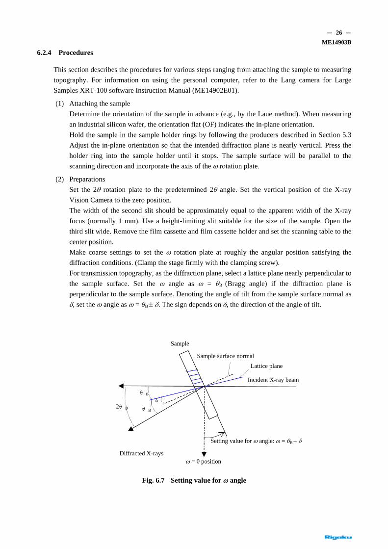
(2) Preparations Set the 2θ rotation plate to the predetermined 2θ angle. Set the vertical position of the X-ray Vision Camera to the zero position. The width of the second slit should be approximately equal to the apparent width of the X-ray focus (normally 1 mm). Use a height-limiting slit suitable for the size of the sample. Open the third slit wide. Remove the film cassette and film cassette holder and set the scanning table to the center position. Make coarse settings to set the ω rotation plate at roughly the angular position satisfying the diffraction conditions. (Clamp the stage firmly with the clamping screw). For transmission topography, as the diffraction plane, select a lattice plane nearly perpendicular to the sample surface. Set the ω angle as ω = θB (Bragg angle) if the diffraction plane is perpendicular to the sample surface. Denoting the angle of tilt from the sample surface normal as δ, set the ω angle as ω = θB ± δ. The sign depends on δ, the direction of the angle of tilt.
Sample
Sample surface normal Lattice plane
Incident X-ray beam
2θB
θB δ
θB
Setting value for ω angle: ω = θB + δ
Diffracted X-rays ω = 0 position
Fig. 6.7 Setting value for ω angle

- 27 - ME14903B
As an example, Table 6.1 lists the calculated results for the possible transmission geometry for a Si wafer of (001) plane orientation. The values are for MoKα1 (λ = 0.070926 nm) X-rays.
Table 6.1 Reflection indices suitable for transmission topography of Si wafer with (001) plane orientation
Unit: Degree
hkl d - (nm) θ 2θ δ ω
111 0.313556 6.49 12.99 35.24 41.76
220 0.19201 10.64 21.29 0 10.65
311 0.16375 12.51 25.02 17.55 30.06
400 0.13577 15.14 30.28 0 15.14
331 0.12459 16.54 33.07 13.26 29.80
422 0.11086 18.66 37.31 24.10 42.75
511 0.10452 19.83 39.67 11.10 30.93
333 0.10452 19.83 39.67 35.26 55.10
531 0.09180 22.72 45.45 9.73 32.46
602 0.08586 24.39 48.78 18.43 42.82
001 040
111
331 422
220 531 602 311 511
Notch or OF position 400
Fig. 6.8 Stereogram for (001) wafer

- 28 - ME14903B
(3) Axial adjustment for sample crystal Generate X-rays and perform axial adjustments for the crystal. To do this, start “Axis set up” (PC operation) and operate the system while observing the X-ray diffraction image with the X-ray Vision Camera. Suppress X-ray output so that the output signal from the X-ray Vision Camera does not saturate. The diffracted X-ray intensity will depend on the sample and the diffraction vector selected. Appropriate X-ray output adjustments will require some operator experience. Open the X-ray shutter, perform the ω scan, and search for a diffracted beam. Fig. 6.9 (a) shows the output image just after the image of the diffracted X-ray beams is captured. Since axial adjustments are incomplete, the diffracted beams in the image for the Kα1 and Kα2 appear as tilted lines. Set the orientation of the crystal by adjusting the in-plane rotation and by finely adjusting the ω angle so that the image is uniform from top to bottom, as shown in Fig. 6.9 (b). The field of view of the X-ray Vision Camera in the dimension of height is approximately 36 mm. If you are measuring a large sample, move the detector vertically while observing the image of the diffracted beam to confirm that the diffraction condition is achieved across the full vertical range of the sample. Make fine orientation adjustments, if necessary.
Kα2
Kα1
D050214A23
(a) Image of diffracted beam captured by ω scan
D050214A24
(b) Image after adjusting orientation
Fig. 6.9 Axial adjustment

- 29 - ME14903B
(4) Determining the position of the third slit Close the X-ray shutter and move the third slit closer to the crystal. Adjust the setting so that the crystal surface and the slit surface are more or less parallel. Position them as close as possible while avoiding collision between the crystal and the slit as the crystal moves back and forth.
(5) Setting the width of the third slit Open the X-ray shutter once again and observe the image of the diffracted X-ray beam. Select the adjustment axis from “slit right” and “slit left,” moving the slits to narrow the slit. After confirming that the slits block the image of the diffracted X-ray beam, set the slits to make the slit width slightly larger than at the position where the image is blocked. Adjust the position of the other slits in a similar manner.
(6) Setting the scanning range Move the scanning stage while observing the image of the diffracted X-ray beam. Continue moving the stage until the image of the diffracted X-ray beam disappears at the crystal edge. Stop the stage here and register the position of the crystal edge. If the stage is in the negative range, use the left edge register button. If the stage is in the positive range, use the right edge register button. When the crystal edge positions are registered, the XRT-100 system will automatically update scanning range settings for traverse topography. If the diffracted X-ray beam shifts from the diffraction condition as the scanning table moves, the sample is warped. In this case, follow the instructions for acquiring the curve correction data given under Item (7).
(7) Setting sample curve correction data If the sample is bent, set the sample curve correction data. By following the procedures indicated in the operation program move the sample position in stepwise increments, acquire ω value for the precise Bragg condition and crystal edge information by ω scan adjustments, and register the information. Use the acquired step data to interpolate the data. Select the interpolation method from the spline function and first-degree to fifth-degree polynomial interpolation based on the least mean squares method. When the first-degree polynomial is selected, the average curvature radius is calculated and displayed. If the sample is warped significantly, ω correction may fail in the exposure step for the traverse topography described in Item (9), and the equipment may generate an error and stop. Curve corrections are possible for samples with a curvature radius of 5 m or greater.
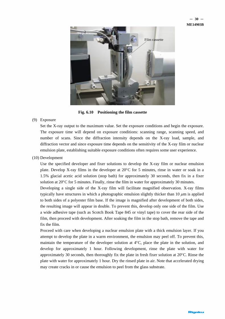
(8) Positioning the film cassette (Fig. 6.10) Insert an X-ray film or nuclear emulsion plate into the film cassette and mount on the camera. Insert the film cassette into the cassette holder, support with the cassette bracket, and fasten in place with the clamp screw. Set the film cassette as close to the sample as possible. For this purpose, set the film cassette as close to perfectly parallel to the surface of the third slit as possible while avoiding collisions with the third slit within the scanning range for the scanning stage. Read the distance between the sample and the film with the reference lines and scale.
- 30 - ME14903B
Film cassette
Fig. 6.10 Positioning the film cassette
(9) Exposure Set the X-ray output to the maximum value. Set the exposure conditions and begin the exposure. The exposure time will depend on exposure conditions: scanning range, scanning speed, and number of scans. Since the diffraction intensity depends on the X-ray load, sample, and diffraction vector and since exposure time depends on the sensitivity of the X-ray film or nuclear emulsion plate, establishing suitable exposure conditions often requires some user experience.
(10) Development Use the specified developer and fixer solutions to develop the X-ray film or nuclear emulsion plate. Develop X-ray films in the developer at 20°C for 5 minutes, rinse in water or soak in a 1.5% glacial acetic acid solution (stop bath) for approximately 30 seconds, then fix in a fixer solution at 20°C for 5 minutes. Finally, rinse the film in water for approximately 30 minutes. Developing a single side of the X-ray film will facilitate magnified observation. X-ray films typically have structures in which a photographic emulsion slightly thicker than 10 µm is applied to both sides of a polyester film base. If the image is magnified after development of both sides, the resulting image will appear in double. To prevent this, develop only one side of the film. Use a wide adhesive tape (such as Scotch Book Tape 845 or vinyl tape) to cover the rear side of the film, then proceed with development. After soaking the film in the stop bath, remove the tape and fix the film. Proceed with care when developing a nuclear emulsion plate with a thick emulsion layer. If you attempt to develop the plate in a warm environment, the emulsion may peel off. To prevent this, maintain the temperature of the developer solution at 4°C, place the plate in the solution, and develop for approximately 1 hour. Following development, rinse the plate with water for approximately 30 seconds, then thoroughly fix the plate in fresh fixer solution at 20°C. Rinse the plate with water for approximately 1 hour. Dry the rinsed plate in air. Note that accelerated drying may create cracks in or cause the emulsion to peel from the glass substrate.

- 31 - ME14903B
6.2.5 Simultaneous reflection image
A Lang topograph will sometimes contain streaks along the dimension of width. This is a diffraction phenomenon known as “simultaneous reflection” which always appears when the sample has a large aperture.
X-ray source Incident slit
Diffraction slit
φ
Film
Lattice plane causing simultaneous reflection
Simultaneous reflection image
χ Major diffraction image
ω Scanning direction
Fig. 6.11 Rough sketch of simultaneous reflection
As shown in Fig. 6.11, X-rays emitted from the X-ray source are shaped by the long incident slit and irradiated onto the sample. The ω angle and φ angle are adjusted to set the orientation of the sample so that the diffraction conditions on the specified lattice plane are satisfied. More specifically, the image of the diffracted X-ray beam is acquired under conditions whereby the lattice plane and longitudinal direction of the incident slit are parallel and the incident angle agrees with the Bragg angle. The image of the diffracted X-ray beam satisfies the diffraction condition across the full vertical range of the sample and is projected onto the film as a reed-shaped image. In addition to this major diffraction image, the incident X-rays (arrow in the Fig.) may satisfy the diffraction condition for part of the sample. The diffracted beam is projected through the diffraction slit as a spot onto the X-ray film. This diffraction image occurs simultaneously with the primary image of the diffracted X-ray beam and is called a simultaneous reflection. A simultaneous reflection occurs because many lattice planes generating diffractions are oriented in several dimensions and directions in the crystal and because the incident beam diverges vertically. Simultaneous reflections are not restricted to characteristic X-rays; they can also occur with the wavelength component (Laue image) selected by the lattice plane causing the diffraction. With Lang’s method, the sample and X-ray film are scanned parallel to the sample surface during exposure. The X-ray image corresponding to the outer shape of the sample is acquired by the primary image of the diffracted beam, and the simultaneous reflection image forms streaks along the dimension of width (scanning direction) that overlaps the primary image. While the simultaneous reflection image overlaps the primary image of the diffracted beam, you will sometimes observe a white image. This is a residue of the simultaneous reflection. Is it possible to prevent simultaneous reflections? Simultaneous reflections are basically a diffraction phenomenon and cannot be removed. However, one can move the position at which they appear via

- 32 - ME14903B
rotation (χ rotation) around the normal of the lattice plane, as shown in Fig. 6.11. Setting strict (narrow) widths for the diffraction slit also helps reduce the number of the simultaneous reflections. The distance between the sample and film is called the camera length. Using a large camera length including the diffraction slit position can remove simultaneous reflections. Simultaneous reflections do not occur along the horizontal dimension; they are emitted downward or upward. Thus, the problem can be solved by increasing the camera length to reach a position at which a simultaneous reflection does not overlap the primary image of the diffracted beam. To optimize resolution, make the camera length as short as possible; long camera lengths are generally undesirable. It should be taken into consideration that simultaneous reflections are inevitable in high-resolution topography using X-ray film. However, since the resolution of topography with imaging plates (IP) is limited due to characteristics of IP, it may in certain cases be advantageous to increase the camera length to eliminate simultaneous reflections.
Simultaneous reflection
The simultaneous reflection isprojected downward from here.
(a) Fixed image of central area (b) Traverse topograph (negative)
Fig. 6.12 Example of simultaneous reflection: (001) sapphire wafer with diffraction vector of 2-10

- 33 - ME14903B
6.2.6 Scattered X-ray shielding plate for transmission topography
For transmission topography, attach the scattered X-ray shielding plate to obtain a clear topograph with low background. This method is useful when long exposure times are required for a thick sample or for crystals characterized by large absorption. As shown in Fig. 6.13, incident X-rays are scattered by air or at the slit edges, generating scattered X-rays. These scattered X-rays pass through the third slit, reach the film, and are recorded as background. Use the scattered X-ray shielding plate to prevent this. The scattered X-ray shielding plate blocks scattered X-rays with its protruding wings and keeps them from reaching the film. Fig. 6.14 illustrates the effectiveness of using the scattered X-ray shielding plate, showing the background of a topograph captured without a scattered X-ray shielding plate.
Third slit
Sample
Second slit
Film cassette Scattered X-rays
Incident X-rays
Diffracted X-rays
Scattered X-ray shielding plate for transmissiontopography
Fig. 6.13 Attaching the scattered X-ray shielding plate for transmission topography
Without scattered X-ray shielding plate (D040318A04) With scattered X-ray shielding plate (D040318A05)
Fig. 6.14 Effectiveness of scattered X-ray shielding plate: GaAs g = 220 (negative)

- 34 - ME14903B
6.3 Section topography
Section topography is a method for investigating the distribution of lattice defects along the dimension of depth by removing simultaneous reflections in a sample crystal. This section discusses section topography principles, tools, and imaging procedures.
6.3.1 Principles of section topography
X-ray diffraction image captures made with a stationary sample and stationary nuclear emulsion plate are referred to as section topography. In this case, the width of the incident X-rays is narrowed to approximately 10 µm by the incident slit, which is placed close to the sample. A diffraction image captured with this method is called a section topograph.
Incident X-rays
C B
A
Image of diffracted beam withstrong intensity correspondingto the defect
Lattice defect
Lattice plane
Sample crystal
Nuclear plate or film
Slit width 10 µm
Fig. 6.15 Configuration of section topography (plan view)
Fig. 6.15 shows the configuration of a section topography in plan view. The X-ray incident beam is narrowed. If the diffraction conditions are met for the characteristic X-rays at the lattice plane of the sample crystal, the X-rays are diffracted. As the diffracted X-rays undergo multiple scattering in the crystal, they spread in the triangular region ABC and appear as an image with widths in the transmission and diffraction axes. If the crystal has relatively few flaws, interference fringes (Pendellösung fringes) will appear, caused by interference between the diffracted and transmitted waves. The visual appearance of the interference fringes is used to evaluate the perfection of the crystal.
When the crystal contains a dislocation in the direction of the direct X-ray beam as shown in the figure 6.15, a diffracted beam is generated nearby with strong intensity corresponding to the defect (defect image). The position of the defect image in the diffracted beam image recorded on the photographic plate provides information on the position of the defect with respect to depth. That is, it provides

- 35 - ME14903B
information on the lattice defect distribution along the cross section of the crystal. Here, the term “section” is used to mean “cross section.”
In contrast to section topography, the ordinary topography measured by scanning is called traverse topography. Since the image is a projection of a three-dimensional image onto two dimensions, traverse topography is sometimes called projection topography.
6.3.2 Tools for section topography
To obtain a clear section topograph, note the following points:
(i) Use a photographic plate with a fine-grain emulsion capable of producing high resolution (e.g., nuclear emulsion plate) (required).
(ii) Use a narrow incident slit with a width of approximately 10 µm.
(iii) Set the sample close to the 10-µm slit.
(If the distance between the sample and the slit is large, the angular divergence of the X-rays will diffuse the irradiated width even if the slit width is small, rendering the resulting section topograph unsharp.)
The XRT-100CCM system provides an extension slit holder for setting the sample close to the slit. The extension slit holder consists of a support attached to the second slit section and a slit holder into which the slit is inserted. The two components are secured by magnetism. The slits (setting slits) provided are 0.2 mm and 1 mm wide. Use these slits to create the Bragg condition and replace the slit into the 10-µm slit to capture the image. Select the 0.2 mm or the 1 mm slit as follows: If the X-ray source provides a normal focus, use the 1-mm slit; if it provides a fine focus, use the 0.2-mm slit.
Insert into the secondslit position extension slit holder
Support
Support
slit pieces
(a) Support (b) Slit holder and slits
Fig. 6.16 Tools for section topography
6.3.3 Procedures for section topography
Before starting measurement, attach the sample, perform axial adjustments, and set the third slit as for ordinary transmission topography. Then, follow the subsequent procedures given below.
(1) Attach the support for the extension slit to the second slit holder. Note that the support slides vertically. After attaching it, slide the support to set the appropriate vertical position.
(2) Attach the setting slit to the slit holder. If the X-ray focus is normal, use the 1-mm slit. If it is fine

- 36 - ME14903B
focus, use the 0.2-mm slit. Attach the slit to the support and move the slit close to the sample (Fig. 6.17).
extension slit holder
Cassette
(a) Attaching extension slit holder (b) Attaching cassette for Nuclear Emulsion Plate
Fig. 6.17 Setting of section topography
(3) Open the X-ray shutter and adjust the ω axis to the exact Bragg condition.
(4) Replace the slits from the setting slit to the 0.01-mm (10-µm) slit for section topography.
(5) Attach the cassette and launch the control software for section topography and perform topography.
(a) Before heat treatment (b) After heat treatment (c) Optical microscopic imageof etching pits in the cross section of the crystal after heat treatment Section topograph
80μm
Fig. 6.18 Examples of section topograph (negative)
Fig. 6.18 (a) and (b) show section topographs of a Si-CZ crystal before and after heat treatment. Before heat treatment, we see X-ray interference fringes (Pendellösung fringes), indicating that the crystal is relatively free of flaws. Heat treatment precipitates SiOx within the crystal, deforming the lattice and creating a granular contrast. As we see in the topograph, a denuded zone (D.Z.) is formed on the surface of the crystal by the out-diffusion of oxygen.

- 37 - ME14903B
6.4 Surface reflection topography
6.4.1 Principles of surface reflection topography
Lang method (previously described in Section 6.2) is topography in the transmission geometry. Also possible is topography in the reflection geometry. Topography in the reflection geometry was first attempted by Berg in 1931 and refined by Barrett. Berg-Barett topography is now virtually synonymous with reflection topography. Fig. 6.19 shows a plan view and rough sketch of reflection topography. The X-rays emitted from a point X-ray source pass through the slit and irradiate the sample. Select a lattice plane that satisfies the diffraction condition with a small angle of incidence on the sample surface and a diffraction angle (2θ) close to 90 degrees. This setting makes adjustments easier. This type of reflection is known as asymmetric reflection. Asymmetric reflections spread the width of the image of the diffracted beams to approximately ten times the width of the X-ray source, enabling topography of a wide area of the crystal surface. Asymmetric reflections make it possible to set the sample close to the film, increasing resolution. It also makes it easier to position the receiving slit between the sample and the film. Scanning the sample in a manner similar to Lang method allows topography of the entire sample surface.
Slit
Sample crystal X-ray source
Slit
Film
(a) Plan view
Sample crystal Slit
X-ray source
Film
(b) Rough sketch
Fig. 6.19 Surface reflection topography
Berg-Barrett topography is free of any constraints on sample thickness and can be applied to examine a thick sample through which X-rays cannot penetrate. As with Lang’s method, the principle of dislocation image formation is extinction contrast. In general, as the state of the crystal approaches perfection, diffraction intensity declines (a phenomenon known as the extinction effect). If such crystals contain lattice distortion due to lattice defects or other factors, the defective area generates intense diffracted X-ray beams, producing the contrast of the defect image and generating images of

- 38 - ME14903B
dislocations on the surface of the crystal. However, the contrast of the dislocation image is weaker than with Lang method performed in transmission geometry. If the crystal contains a region having a different orientation, this region has a different degree of diffraction condition satisfied and causes the intensity to change. This is a principle of image formation known as orientation contrast. It is suitable for observing a lineage, which is an assembly of dislocations, with orientation shifting in subgrains. Fluorite crystals often consist of subgrains with slightly different orientations. With such samples, orientation contrast makes it possible to observe the domain structure. The method is also useful for the topography of heteroepitaxial films (thin film crystals deposited on a substrate crystal, with the same orientation but composition different from that of the substrate). The information acquired by surface reflection topography includes defects in layers within several to 100 µm from the surface. Tables 6.2 to 6.4 show the reflection indices suitable for reflection topography for a Si wafer, a GaAs wafer and a fluorite crystal. The diffraction angle values are for the CuKα1 line. The third slit and the film cassette have a rotation mechanism along the axis of the diffracted X-ray beam and a precession mechanism. Adjusting the rotation and precession reduces distortion in the topography due to the cosine effect.
Table 6.2 Reflection indices suitable for reflection topography of Si wafer
with (001) plane orientation Unit: degree
Reflection index Bragg angle θ Diffraction angle 2θ Lattice plane tilting δ Incident angle α
224 44.01 88.03 35.26 8.75
115 47.48 94.95 15.79 31.68
404 53.35 106.71 45 8.35
Table 6.3 Reflection indices suitable for reflection topography of GaAs wafer
with (001) plane orientation Unit: degree
Reflection index Bragg angle θ Diffraction angle 2θ Lattice plane tilting δ Incident angle α
224 41.87 83.74 35.26 6.6
115 45.07 90.13 15.8 29.27
404 50.42 100.83 45 5.41
Table 6.4 Reflection indices suitable for reflection topography of fluorite crystal with (111) plane orientation
Unit: degree Reflection index Bragg angle θ Diffraction angle 2θ Lattice plane tilting δ Incident angle α
331 37.94 75.87 29.5 8.4
422 43.7 87.39 19.5 24.2
511 47.1 94.24 39.94 8.2
440 52.9 105.8 35.3 17.6
- 39 - ME14903B
6.4.2 Procedures for surface reflection topography
This section describes procedures for reflection topography. Use the holder rings to grasp the sample, as in transmission topography.
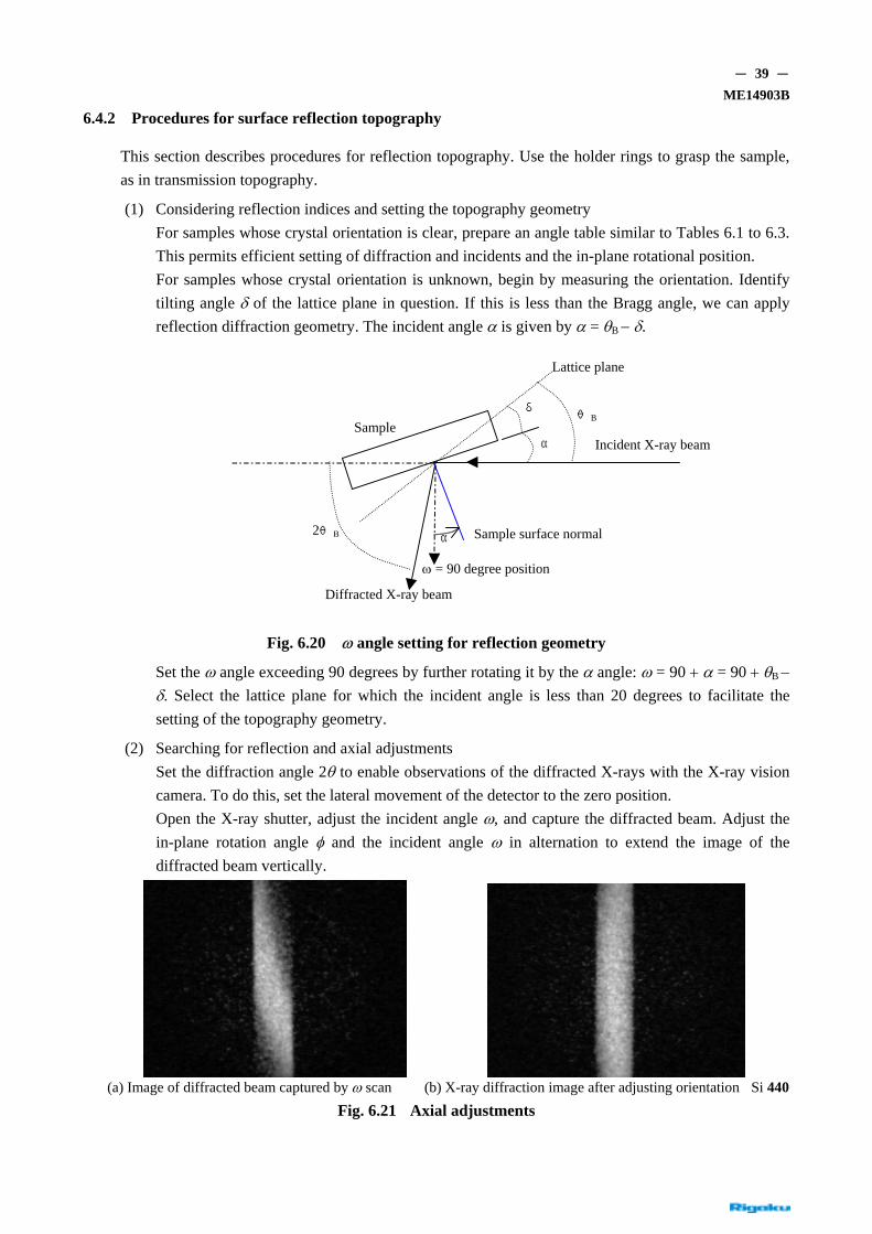
(1) Considering reflection indices and setting the topography geometry For samples whose crystal orientation is clear, prepare an angle table similar to Tables 6.1 to 6.3. This permits efficient setting of diffraction and incidents and the in-plane rotational position. For samples whose crystal orientation is unknown, begin by measuring the orientation. Identify tilting angle δ of the lattice plane in question. If this is less than the Bragg angle, we can apply reflection diffraction geometry. The incident angle α is given by α = θB − δ.
ω = 90 degree position
Lattice plane
δ
α
θB
Incident X-ray beam Sample
2θB Sample surface normal α
Diffracted X-ray beam
Fig. 6.20 ω angle setting for reflection geometry
Set the ω angle exceeding 90 degrees by further rotating it by the α angle: ω = 90 + α = 90 + θB − δ. Select the lattice plane for which the incident angle is less than 20 degrees to facilitate the setting of the topography geometry.
(2) Searching for reflection and axial adjustments Set the diffraction angle 2θ to enable observations of the diffracted X-rays with the X-ray vision camera. To do this, set the lateral movement of the detector to the zero position. Open the X-ray shutter, adjust the incident angle ω, and capture the diffracted beam. Adjust the in-plane rotation angle φ and the incident angle ω in alternation to extend the image of the diffracted beam vertically.
(a) Image of diffracted beam captured by ω scan (b) X-ray diffraction image after adjusting orientation Si 440
Fig. 6.21 Axial adjustments

- 40 - ME14903B
(3) Setting the scanning range for the traverse stage Scan the traverse stage while monitoring the image of the diffracted X-ray beam. The image of the diffracted beam disappears at the crystal edge. Stop scanning at this point. Do this at both ends of the crystal and register the scanning range.
(4) Acquiring curve correction data when the sample is warped If the sample is warped, the beam shifts from the diffraction condition with the scan of the traverse stage, and the X-ray image disappears. In such cases, acquire the step data for the curve correction and perform scanning with the correction. Here, the XRT-100 system supports only simple correction. If the sample is warped significantly at a curvature radius of 5 m or less, the correction cannot track the curvature and will generate an error.
(5) Setting the variable slit Set the precession, proceeding carefully to keep the slit from contacting the sample within the scanning range, and position as close to the sample as possible. Adjust the position of the right and left slits to control the aperture of the slit to avoid blocking the diffracted X-ray beam.
(6) Attaching the film cassette Insert an IP or an X-ray film into the cassette and attach the cassette to the cassette holder with the cassette bracket. Set the ψ angle along the axis of the diffraction angle by visual observation. Set the precession while taking steps to keep the cassette from contacting the third slit (S3) within the scanning range. Position as close as possible to the sample.
(7) Developing exposed film Set the conditions, including the number of scans, and expose the sample, then develop the film.
(8) Devising imaging Shift the ω angle so that it is slightly offset from the exact Bragg angle in imaging to increase the contrast of the topograph. Vary the ω angle and take a series of topographs to acquire a topographical rocking curve containing angle information. Scanning represents a type of averaging operation. Topography without scanning is also possible. Combined with the stepwise movement of the stage, this will produce a striped topograph. Figs. 6.22 and 6.23 show examples of topographs.
D010613A14 D010613A13
(a) (b)
Fig. 6.22 Example of topography: effect of offset topography (negative)

- 41 - ME14903B
Image (a) is taken at the exact Bragg angle, while Image (b) is taken slightly offset from the exact Bragg angle to the smaller angle. Offset imaging is more sensitive to changes in orientation. The diffraction vector is 440.
(a) (b)
D010613A15 D010613A16
Image loss Overlapped image
Film position
X-rays
(c)
Fig. 6.23 Example of topography: striped topography (D010613A15,16) (negative)
Image (a) is a traverse topograph captured by the scanning technique. Image (b) is a topograph measured while the traverse stage is moved stepwise at constant intervals with repeated time exposures. The diffraction vector is 422, and the topograph is captured with asymmetric reflection with an incident angle of approximately 14 degrees. The topographs clearly show the subgrain structure with orientation contrast. Image overlaps and image losses occur at the grain boundary due to changes along the axis of the diffracted beam as well as changes in the degree of diffraction conditions satisfied. Fig. 6.23 (c) schematically illustrates this behavior.

- 42 - ME14903B
6.4.3 Scattered X-ray shielding plate for reflection topography
When measuring a small sample with a straight slit, attach the scattered X-ray shielding plate to prevent fogging caused by scattered X-rays. The plate extends the right piece of the third slit and shields against scattered X-rays.
Second slit
Third slit
Scattered X-rays
Scattered X-ray shielding plate
Sample Film cassette
Fig. 6.24 Scattered X-ray shielding plate for reflection topography

- 43 - ME14903B
6.5 Darkroom equipment
This section describes the darkroom equipment required for X-ray topography.
6.5.1 X-ray film and nuclear plates
(1) X-ray film Fuji industrial X-ray film (manufactured by Fujifilm Corporation) may be used. Five types of films are available with Ix series numbers of #150, #100, #80, #50, and #25. Films with lower numbers use finer grains but have lower sensitivity. The #80 film is recommended as the standard film for X-ray topography. The size of the film is 10 inches by 12 inches (quartered). Twenty-five individual films are provided per box. Other sizes are also available: 3.1/3 inches × 12 inches and 14 inches × 17 inches (halved). Boxes with 50 films and 100 films are also available. Kodak (US) and Agfa (Germany) manufacture equivalent products.
(2) Nuclear emulsion plates
Use nuclear plates manufactured by Ilford for topography. Ilford manufactures various types of emulsion, including L4 and G5. L4 incorporates the finest grains. The emulsion thicknesses best suited to topography are 25 µm and 50 µm. Plate dimensions are 1 inch × 3 inches. A standard box contains a dozen plates. Plates measuring 3 inches × 3 inches are also available.
(3) Using other films
FG film for electron microscope and medical film for mammography (high-resolution film for breast cancer examination) are single emulsion, high-resolution films, although with low sensitivity.
6.5.2 Developer
The specified X-ray film developer and fixer are listed below. Developer: Rendol, 2 liters Fixer: Renfix, 2 liters Both are manufactured by Fujifilm Corporation. Dissolve in separate solutions of warm water to prepare developer and fixer solutions. For the stopper solution, use a 1.5% aqueous solution of acetic acid (use Fuji acetic acid 1l). Other solutions used include the Fuji QW (quick-washing) agent and Fuji Film Driwel Wetting agent. Develop the nuclear emulsion plate with Kodak D-19 developer or ID-19 developer.
6.5.3 Darkroom equipment
Select the darkroom equipment from brochures provided by photo supply manufacturers (for example, Hansa by Hansa Co., Ltd. or King by Asanuma & Co., Ltd.).
Tools for development: Trays, tongs, jars for storing solutions, measuring beaker (2-liter), funnel, stirring rod, photo sponge, and thermometer
Darkroom facility: Ideally, the darkroom should contain a sink. A temporary space screened by blackout curtains or a space with basic darkroom facilities can be used as alternatives.
Darkroom equipment: Darkroom lamp (with various filters, including those for X-rays), darkroom timer, scissors, paper cutter (for cutting films),

- 44 - ME14903B
low-temperature thermostatic bath (for developing nuclear plates)
Printing equipment: Enlarger, easel, focusing scope, monochromatic paper, developer and fixer solution for printing paper
Scanner: The image can be transferred to a PC using a film scanner (e.g., Epson F-3200 film scanner for personal hobby use).
Micrographs: It is also possible to take low-power micrographs. This is particularly useful for topographic observations with nuclear plates.
Also prepare tape for one-sided development (Scotch 845 Book tape or wide vinyl tape) of X-ray films.

- 45 - ME14903B
7. Maintenance
7.1 Replacing the mylar films on the sample holder rings
(1) Remove the broken mylar film. Remove the adherend surface with the blade of a knife and clean the surface with a cleaner (e.g., benzene).
(2) Prepare a cylinder with an inner diameter of 125 mm to 130 mm. (Ideally, use an empty can (i). Open a hole to allow air to pass through.)
(3) Stretch the mylar films (ii) tight at the bottom of the empty can and fasten with several dozen rubber bands (iii). Reinforce with Scotch tape.
(4) Apply a thin coat of the adhesive provided with the system on the adherend mylar surface of the holder ring (iv), then place the mylar atop it. Place a weight (v) of approximately 5 kg to 6 kg on the mylar.
(5) After an hour, the mylar film will have adhered completely. Remove excess mylar film with the blade of a knife.
(6) After the mylar film is attached to each of the two holder rings, make approximately a dozen holes in the mylar film to allow air to pass through.
(i) Empty can
(i) Empty can
(ii) Mylar film
(iii) Rubber bands
(v) Weight
(iv) Holder ring
Reinforced by tape
Fig. 7.1 Attaching mylar films
- 46 - ME14903B
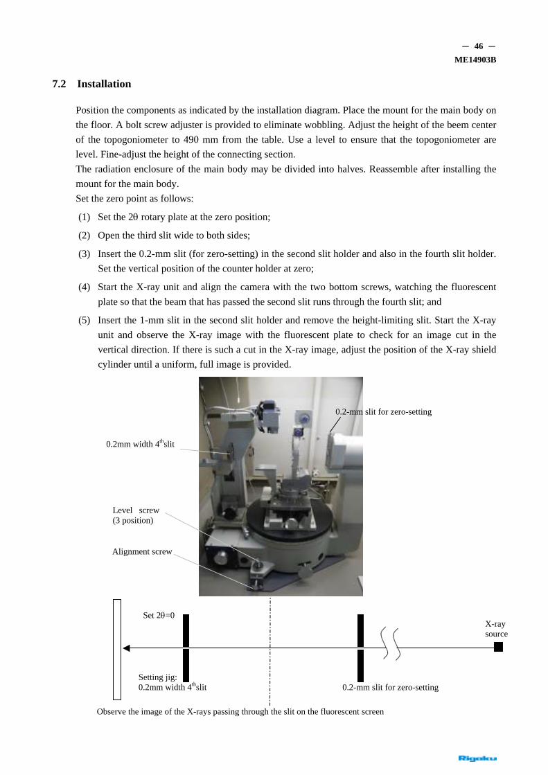
7.2 Installation
Position the components as indicated by the installation diagram. Place the mount for the main body on the floor. A bolt screw adjuster is provided to eliminate wobbling. Adjust the height of the beem center of the topogoniometer to 490 mm from the table. Use a level to ensure that the topogoniometer are level. Fine-adjust the height of the connecting section. The radiation enclosure of the main body may be divided into halves. Reassemble after installing the mount for the main body. Set the zero point as follows:
(1) Set the 2θ rotary plate at the zero position;
(2) Open the third slit wide to both sides;
(3) Insert the 0.2-mm slit (for zero-setting) in the second slit holder and also in the fourth slit holder. Set the vertical position of the counter holder at zero;
(4) Start the X-ray unit and align the camera with the two bottom screws, watching the fluorescent plate so that the beam that has passed the second slit runs through the fourth slit; and
(5) Insert the 1-mm slit in the second slit holder and remove the height-limiting slit. Start the X-ray unit and observe the X-ray image with the fluorescent plate to check for an image cut in the vertical direction. If there is such a cut in the X-ray image, adjust the position of the X-ray shield cylinder until a uniform, full image is provided.
0.2-mm slit for zero-setting
O
0.2mm width 4thslit
Alignment screw
Level screw(3 position)
Set 2θ=0 X-ray source
Setting jig: 0.2mm width 4thslit 0.2-mm slit for zero-setting
bserve the image of the X-rays passing through the slit on the fluorescent screen

- 47 - ME14903B
Fig. 7.2 Zero setting
Appendix
A Data
Table 1 2θB
(1) Si a=0.5430nm
2θB (°) hkl d (nm)
AgKα MoKα CuKα
111 0.3135 10.23 12.99 28.45
220 0.19198 16.75 21.29 47.31
311 0.1637 19.67 25.02 56.13
400 0.13575 23.78 30.29 69.13
331 0.12457 25.95 33.08 76.38
422 0.11084 29.23 37.31 88.04
511
333 0.10450 31.05 39.67 94.96
440 0.09599 33.88 43.36 °106.72
531 0.09178 35.48 45.45 114.11
1/μ(mm) 1.26 0.64 0.07
(2) Ge a=0.5657nm
2θB (°) hkl d (nm)
AgKα MoKα CuKα
111 0.32661 9.82 12.47 27.28
220 0.20000 16.08 20.43 45.30
311 0.17056 18.88 24.00 53.69
400 0.14143 22.81 29.04 66.00
331 0.12978 24.89 31.72 72.81
422 0.11547 28.03 35.77 83.68
511
333 0.10887 29.77 38.02 90.06
440 0.10000 32.48 41.54 100.75
531 0.0956 34.01 43.54 107.32
1/μ(mm) 0.055 0.029 0.025

- 48 - ME14903B
(3) GaAs a=0.56534nm
2θB (°) hkl d (nm)
AgKα MoKα CuKα
111 0.32642 9.83 12.47 27.30
220 0.19989 16.09 20.44 45.33
311 0.17047 18.89 24.01 53.72
400 0.14135 22.82 29.06 66.04
331 0.12971 24.90 31.73 72.86
422 0.11541 28.05 35.79 83.74
511
333 0.10881 29.80 38.04 90.13
440 0.09995 32.50 41.57 100.83
531 0.09557 34.03 43.56 107.41
1/μ(mm) 0.051 0.027 0.023
Table 2 Kα Doublet
Doublet Natural breadth
△λα2-α1
nm △λα2-α1/λα1
△λα1
nm △λα1/λα1
AgKα
MoKα
CuKα
0.000442
0.000428
0.000382
7.9×10⁻³
6.03×10⁻³
2.48×10⁻³
0.000029
0.000029
0.000057
5.1×10⁻⁴
4.1×10⁻⁴
3.8×10⁻⁴

- 49 - ME14903B
B Guide for references related to topography
• A. Authier: “Dynamical Theory of X-ray Diffraction” revised edition, Oxford (2004) chapter 7
• D.K.Bowen & B.K.Tanner:High resolution X-ray Diffractometry and Topography, Taylor&Francis(1998)
• A. R. Lang: “International Tables for Crystalography Volume C” Part2, 2.7 Topography, KULWER ACADEMIC PUBLISHERS (1992)
• B.K.Tanner & D.K.Bowen ed.: “Characterization of Crystal Growth Defects by X- ray Method”, Plenum Press (1980)
• B.K.Tanner: “X-ray Diffraction Topography”, Pergamon Press (1976)