Gamma-Ray Imaging Spectrometry - Lawrence Livermore National
X-RAY OPTICS
Eberhard Spiller
Lawrence Livermore National Laboratory Livermore, Ca 94550
INTRODUCTION
We summarize recent progress in x-ray optics, emphasizing topics not covered elsewhere at the conference. We concentrate on optics for high resolution imaging like zone plates and multilayer mirror optics and the application of these elements to x-ray microscopy, astronomy and lithography.
The advances in x-ray optics during the last 25 years were facilitated by the availability of bright synchrotron radiation sources, the invention of multilayer x-ray mirrors with high reflectance, and the development of high resolution zone plates. The high brightness and good collimation of modern synchrotron radiation sources transformed some of the older schemes, for example x-ray waveguides, focussing capillaries or hollow tubes, and x-ray lenses from laboratory demonstrations to useful tools.
OPTICAL CONSTANTS
The first challenge for x-ray optics was already noticed by Riintgen in the first month after his discovery: the refractive index of all materials is close to 1, and all materials have absorption. The refractive index of a material in the x-ray range is usually expressed as
l-J2 jj =l-~+@-l-p 2n: %(fi -if,>, (1)
where 6 is the deviation of the refractive index from one, p is the absorption index, and f,, f2 are the real and imaginary parts of the atomic scattering factors. N, t is the number of atoms per volume and r0 is the classical electron radius r, = 2.82 . lo-l3 cm. The atomic scattering factors for all elements [l] are available on the Internet (http://www-cxro.lbl.gov/optical-constants/). f, is close to the number of “free” electrons per atom, i.e. electrons with a binding energy less than the photon energy, and Nat fi is the effective number of free electrons per volume. For large photon energies and away from absorption edges we have approximately 6 0~ h2, p m 3L3, We can introduce a quality factor N = g/27$ which represents the maximum absorption limited phase retardation of a material normalized to 27c[2]. N is proportional to l/h and becomes large for short wavelengths or high photon energies. If one accepts the inconvenience caused by the low values of 6 (long focal length of lenses, low reflectivity from a single boundary) it is possible to produce high quality lenses or mirrors for short wavelengths where N is large by using many individual lenses[3] or many reflections.
Copyright(C)JCPDS-International Centre for Diffraction Data 2000, Advances in X-ray Analysis, Vol.42 297Copyright(C)JCPDS-International Centre for Diffraction Data 2000, Advances in X-ray Analysis, Vol.42 297ISSN 1097-0002

This document was presented at the Denver X-ray Conference (DXC) on Applications of X-ray Analysis. Sponsored by the International Centre for Diffraction Data (ICDD). This document is provided by ICDD in cooperation with the authors and presenters of the DXC for the express purpose of educating the scientific community. All copyrights for the document are retained by ICDD. Usage is restricted for the purposes of education and scientific research. DXC Website – www.dxcicdd.com
ICDD Website - www.icdd.com
ISSN 1097-0002
PROMISES AND CHALLENGES
Diffraction limits the resolution of optical elements, and the short wavelengths of x rays should allow drastically higher resolution than is available in the visible region. This high resolution has been achieved in the reconstruction of crystalline structures from x-ray diffraction patterns, while traditional one step imaging methods have surpassed the resolution of visible optics only during the last decade. Challenges are the tighter tolerances on metrology and fabrication and the fact that multi- component elements (multiple lenses, multilayer mirrors, zone plates) are needed to compensate for the small values of the retractive index. Metrology and fabrication capabilities of mirror surfaces have now reached the Angstrom level[4] and should permit normal incidence mirrors for wavelengths as short as 5OA and resolutions around 2OOA. The resolution limit of zoneplates is equal to that of the lithographic tool used to write the pattern with best values also in the same range.
IMAGING SYSTEMS FOR X RAYS
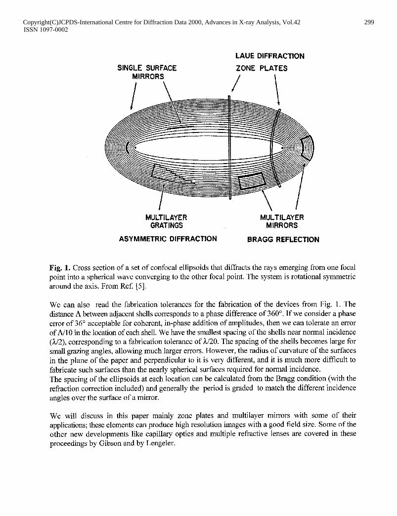
A hologram of a point source images a source point into an image point, and several of the new imaging devices can be visualized as sections of such an hologram. Fig. 1 shows the interferogram (hologram) produced by the superposition of a spherical wave diverging from the source (object) with a spherical wave converging to an image. It consists of sets of confocal ellipsoids. Each of the lines in the figure represents a node of the standing-wave pattern in the interferogram. We can consider each of these nodes as a mirror that produces a perfect image of the source point. The optical path between source and image increases by one wavelength 3L when we move from one node or mirror to the next, which means the contributions from all mirrors add in phase. For a practical application it is not necessary and usually not desirable to fabricate the full set of ellipsoids; only a small section has to be fabricated. Some of the possible sections are indicated in the figure. They are: . Single-surface mirrors. These mirrors usually have very small reflectivities near normal
incidence. Reflectivities are larger at small grazing angles of incidence, however, mirrors can accept only a small aperture for this case and can image only very small fields.
. Multilayer structures have enhanced reflectivities and produce good images with useful field size if used near normal incidence.
. Multilayer gratings are produced for high spectral resolution.
. Circular rings or elliptical rings (zone plates) are obtained in perpendicular or oblique cross sections through the ellipsoids.
The ellipsoids become paraboloids if the source point in Fig. 1 moves toward the left to infinity. If the image moves at the same time to infinity at the right, the system approaches a set of planes. The structures are then analogs to reflecting Bragg crystals, the multilayer grating corresponds to an asymmetrically cut crystal, thin zone plates become transmission gratings, and thick zone plates are represented by the planes of a crystal used in the Laue diffraction geometry.
Copyright(C)JCPDS-International Centre for Diffraction Data 2000, Advances in X-ray Analysis, Vol.42 298Copyright(C)JCPDS-International Centre for Diffraction Data 2000, Advances in X-ray Analysis, Vol.42 298ISSN 1097-0002
SINGLE SURFACE M1RRORS
LAUE DIFFRACTION
ZONE PLATES / \
MULTILAYER MULTlLAYER GRATINGS MIRRORS
ASY MMETRK DIFFRACTION BRAGG REFLECTION
Fig. 1. Cross section of a set of confocal ellipsoids that diffracts the rays emerging from one focal point into a spherical wave converging to the other focal point. The system is rotational symmetric around the axis. From Ref. [Sj.
We can also read the fabrication tolerances for the fabrication of the devices from Fig. 1, The distance A between adjacent shells corresponds to a phase difference of 360”. If we consider a phase error of 36” acceptable for coherent, in-phase addition of amplitudes, then we can tolerate an error of A/10 in the location of each shell. We have the smallest spacing of the shells near normal incidence (A/2), corresponding to a fabrication tolerance of h/20. The spacing of the shells becomes large for small grazing angles, allowing much larger errors. However, the radius of curvature of the surfaces in the plane of the paper and perpendicular to it is very different, and it is much more difficult to fabricate such surfaces than the nearly spherical surfaces required for normal incidence. The spacing of the ellipsoids at each location can be calculated from the Bragg condition (with the refraction correction included) and generally the period is graded to match the different incidence angles over the surface of a mirror.
We will discuss in this paper mainly zone plates and multilayer mirrors with some of their applications; these elements can produce high resolution images with a good field size. Some of the other new developments like capillary optics and multiple refractive lenses are covered in these proceedings by Gibson and by Lengeler.
Copyright(C)JCPDS-International Centre for Diffraction Data 2000, Advances in X-ray Analysis, Vol.42 299Copyright(C)JCPDS-International Centre for Diffraction Data 2000, Advances in X-ray Analysis, Vol.42 299ISSN 1097-0002
ZONE PLATES AND X-RAY MICROSCOPY
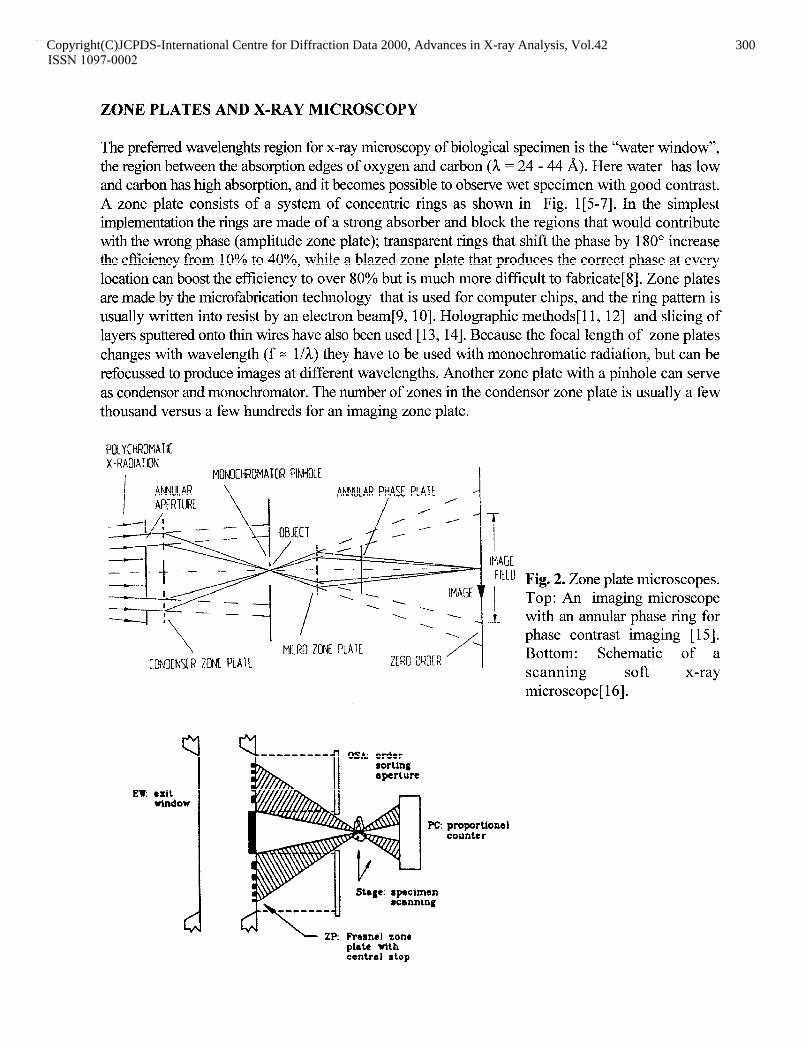
The preferred wavelenghts region for x-ray microscopy of biological specimen is the “water window”, the region between the absorption edges of oxygen and carbon (3L = 24 - 44 A). Here water has low and carbon has high absorption, and it becomes possible to observe wet specimen with good contrast. A zone plate consists of a system of concentric rings as shown in Fig. 1[5-71. In the simplest implementation the rings are made of a strong absorber and block the regions that would contribute with the wrong phase (amplitude zone plate); transparent rings that shift the phase by 180” increase the efficiency from 10% to 40%, while a blazed zone plate that produces the correct phase at every location can boost the efficiency to over 80% but is much more difficult to fabricate[8]. Zone plates are made by the microfabrication technology that is used for computer chips, and the ring pattern is usually written into resist by an electron beam[9, lo]. Holographic methods[ 11, 121 and slicing of layers sputtered onto thin wires have also been used [ 13,141. Because the focal length of zone plates changes with wavelength (f = l/h) they have to be used with monochromatic radiation, but can be refocussed to produce images at different wavelengths. Another zone plate with a pinhole can serve as condenser and monochromator. The number of zones in the condenser zone plate is usually a few thousand versus a few hundreds for an imaging zone plate.
POLYCHROMATIC X-RROIAlION
I
MONOCH2OMATOR PlNHOtt ANNULAR
\ ANNULAR PHASE PLATE
APERTURF I / /' _I
~=!/!i-~ Ib 0B;IECT , 4 : ', y 17
4 :wv 42ii!!
+@==zqyf=y 1 Ik ‘. I -_ .
---Y-- 4 I ’ i -_
\ ' MICRO ZONE PLATE CONDtNSCR ZONL PLATE ZLRO K&R
PC:
Stage: specimen rcnnning
kf4 \ ZP: Fresncl zone
Fig. 2. Zone plate microscopes. Top: An imaging microscope with an annular phase ring for phase contrast imaging [ 1.51. Bottom: Schematic of a scanning soft x-ray microscope[ 161.
proportion41 counter
plate with central stop
Copyright(C)JCPDS-International Centre for Diffraction Data 2000, Advances in X-ray Analysis, Vol.42 300Copyright(C)JCPDS-International Centre for Diffraction Data 2000, Advances in X-ray Analysis, Vol.42 300ISSN 1097-0002
Zone plate microscopes are installed at nearly all synchrotron radiation facilities and are either of the imaging or the scanning type (Fig. 2 see Ref. [6] for a detailed review). The main advantage of the imaging type is the shorter exposure time and the possibility to switch from amplitude contrast to phase contrast by installing an annular phase ring in the rear aperture of the imaging zone plate. In the scanning type the specimen is scanned through a small diffraction limited spot and the rastered image information is stored and displayed on a computer. Many types of images can be recorded, for example transmitted intensity, fluorescence, photoelectrons or any other secondary effect. One can also easily process images taken at different wavelengths near an absorption edge and produce elemental and chemical mapping[ 171. Scanning microscopes require coherent illumination for high resolution, and apertures in the illuminating system are used to filter out a single spatial mode. As a consequence the exposure times are larger than those for an imaging microscope and scanning microscopes are preferably installed at undulator beam lines. Advantages of the scanning system are a reduced radiation damage to the specimen (no lossy imaging element behind the specimen) and the ease of quantitative processing of the data.
Zone plates have also been fabricated for use in reflection, either on top of a Bragg crystal or a multilayer mirror [ 18-201.
MULTILAYER OPTICS
The reflectivity of all mirror materials decreases rapidly with wavelength in the x-ray region, approximately as R 0~ h4 . The important parameter is the momentum transfer q= (4x/k) n sin 8, where 0 is the grazing angle of propagation within a material. For s-polarization the amplitude reflected at the boundary between two materials is simply given by
41 - q2 r =
41 + qz)
where the q values are for the two materials on each side of a boundary. The reflectivity is high for small grazing angles and has its lowest values at normal incidence. Around 3L = 50 A the best single mirrors have normal incidence reflectivities around 10e5. However, one can enhance the reflectivity to values close to one by adding the amplitudes of many boundaries in phase. For R = 10e4 we have a reflected amplitude of 1 Oe2, and the in phase addition of 100 boundaries should add up to a total amplitude close to one. This simple design idea assumes that there is no penetration limit due to absorption, a good assumption for hard x-rays, but often not for soft x-rays. One can minimize absorption if one positions the absorbing material into the nodes of the interference pattern produced by the superposition of the incident and reflected beam of Fig. 1. With an absorption-free spacer material that occupies the antinodes and a sufficient number of layers one could indeed produce a loss-free mirror with 100% reflectivity, even if the refractive index of every material is one[21]. A completely absorption free material for EUV and x-rays does not exist, and for the design of a real multilayer one selects a spacer material with the lowest possible absorption. Light elements just below their absorption edge are usually good choices, and the remaining absorption of the spacer limits the maximum reflectivity. Results of a computer search for the best material combinations have been published[22]. The period A of the multilayer structure that has maximum reflectivity at order m and
Copyright(C)JCPDS-International Centre for Diffraction Data 2000, Advances in X-ray Analysis, Vol.42 301Copyright(C)JCPDS-International Centre for Diffraction Data 2000, Advances in X-ray Analysis, Vol.42 301ISSN 1097-0002
‘grazing angle 8, is obtained from the Bragg equation
\I 26e?7 mh=2Asineo l-- sin*@,
for 6~1, p(t6 . (3)
The square root is the refraction correction ( Snell’s law) which transforms the external angle 6, in vacuum to the internal angle of propagation, and 6,, is a weighted average of the refractive indices of the multilayer materials. The reflectivity of a single boundary and of a multilayer is reduced by deviation from the ideal sharp boundary. The causes can be diffusion, resulting in a gradual transition between the two materials, and boundary roughness; thickness errors in a multilayer also reduce the reflectivity. In a first approximation we can lump all these errors into a parameter o that contains the width of the transition layer, the rms roughness and the rms period error added in quadrature. Assuming Gaussian statistics we can write the reduction of the reflected amplitude of the perfect boundary r0 as[23, 241
r(q) =ro exp( -- q1 TO’) y r. exp(- q**q,
where the Bragg equation has been used to obtain the second part of the equation. For a value of o= A/10 as discussed in Fig. 1 the reflected amplitude is reduced to 82% and the reflected intensity to 67% of its ideal value. Good multilayer systems have o-values in the 3- 5 A range. That means we can expect good reflectivities for multilayers with periods above A = 3OA. Multilayers with periods as low as 1OA have been produced but have low reflectivities. The reduction in the peak reflectivity of a multilayer mirror can be smaller than that given by eq. (4), because the loss in reflectivity of an individual boundary can be compensated for by the contribution from additional deeper boundaries if the quality factor N is large [25]. This condition is fulfilled for hard x-rays and multilayer reflectivities R>70% can easily be obtained for 3L I 1.54 A if the multilayer period is larger than 25 A, and one shifts the Bragg peak to hard x-rays by using the multilayer near grazing incidence. Figure 3 is a plot of the best near normal incidence reflectivities obtained up to now from a database at “www-cxro.lbl.gov/multilayer/survey.htmI”. The highest reflectivities have been obtained near the BeK-edge at A = 114 A [26] and the SiL-edge around 130 A with spacer layers of Be or Si and MO as the high index layer [27, 281. At longer wavelengths the peak reflectivity decreases due to the higher absorption. Y, B, C, and SC are good spacer materials for wavelengths A<100 A. The overall drop in reflectivity with decreasing wavelengths in this range is due to the increased influence of boundary roughness, and reducing boundary roughness is the most difficult challenge for small period multilayers.The database contains also results obtained for hard x-rays and grazing angles of incidence. Multilayer x-ray mirrors have been produced by practically any deposition method. Magnetron sputtering pioneered by Barbee [29] is most widely used: sputtering systems are very stable, and one can obtain the required thickness control simply by timing. Thermal evaporation systems usually use an in-situ soft x-ray reflectometer to control the thickness and an additional ion gun for smoothing of the boundaries [30-321. Many methods have been used to produce the proper grading in the multilayer period, among them shadow masks, substrate tilt, speed control, and computer controlled
Copyright(C)JCPDS-International Centre for Diffraction Data 2000, Advances in X-ray Analysis, Vol.42 302Copyright(C)JCPDS-International Centre for Diffraction Data 2000, Advances in X-ray Analysis, Vol.42 302ISSN 1097-0002

shutters[33-391.
0.6
A
40 100 200 WAVELENGTH (A)
Fig. 3. Achieved peak reflectivity near normal incidence of multilayer structures with spacer layers of C: l 0, B,C: 0 0, Y: T v, Si: A *, SC: 0 0, TiN: A A . From a database at “Www- cxro.lbl.gov/multilayer/survey.ht ml”. The full curves are calculated; the two curves for Co-C are for 70 and 150 periods. The reflectivity 0f10%ath=31.4Aisf0ra370 layer mirror of Cr-Sc with a period A = 16.3 A that was tuned to the region of anomalous dispersion and low absorption of SC by tilting it to 18 o from normal WI-
APPLICATIONS
Multilayer coated mirrors can reflect x-ray beams efficiently at grazing angles up to 10 times larger than the critical angle and at normal incidence for soft x rays with h >3OA in a spectral or angular region around the Bragg angle. These properties make them useful as beam deflectors, spectral filters, collimators or focussing elements [5,41,42]. They are efficient polarizers for incidence angles around 45 O. The imaging performance of mirrors is considerably better at normal incidence than at grazing incidence angles, and optical systems with multilayer mirrors can be used for high resolution imaging. Soft x-ray telescopes for imaging of the solar corona have obtained images with about one order of magnitude better resolution than grazing incidence telescopes; the actual resolution (about 0.5 arcsec) is presently not limited by the quality of the optics but by the detectors, the pointing stability of the spacecraft, and the available photon flux [36,43-451. Pictures from the multilayer mirror telescopes on the SOHO and TRACE spacecraft are available on the Internet at http://umbra.nascom.nasa.gov/eit/ and http://vestige.lmsal.com/TRACE/. A photo from the TRACE satellite is shown in Fig. 4. One pixel of the CCD detector corresponds to 0.5 arcsec and the width of the photo is 3 arcmin. Movies of the coronal activity with the high resolution of Fig. 4 are providing now the experimental data that are required to understand the heating of the corona to more than 106K [45]. With state of the art mirrors one can expect a resolution in the 0.01 arcsec range. However, even for solar astronomy there is concern to have a sufficient photon flux for images with such a high information content. The low intensity horn sources other than the sun will not allow to record high quality x-ray images with a resolution much below 1 arcsec, and grazing incidence telescopes with their larger spectral passband will remain the instruments of choice.
Copyright(C)JCPDS-International Centre for Diffraction Data 2000, Advances in X-ray Analysis, Vol.42 303Copyright(C)JCPDS-International Centre for Diffraction Data 2000, Advances in X-ray Analysis, Vol.42 303ISSN 1097-0002

Figure 4. A portion of the solar corona seen in the Fe IX/X lines at 3L=173A on 7/29/98 from the TRACE spacecraft. Courtesy NASA/TRACE.
Optical systems that use near normal incidence, multilayer coated mirrors are under development for the fabrication of computer chips with linewidth around 0.1 pm (EUV lithography)[46]. A resolution better than 0.1 urn has been demonstrated with spherical mirrors in the Schwarzschild configuration[47]. Cameras with sufficient field for industrial use require large aspheric mirrors with figure errors and finish better than 2 Angstrom. The technology to test and fabricate such mirrors has been developed in the last few years[4,48,49]. The mask that contains the circuit pattern will be used in reflection and be demagnified by the camera, and the multilayer coating of the mask substrate has to be defect free[50]. Progress of the last years indicates that the technical challenges for EUV lithography can be met.
Copyright(C)JCPDS-International Centre for Diffraction Data 2000, Advances in X-ray Analysis, Vol.42 304Copyright(C)JCPDS-International Centre for Diffraction Data 2000, Advances in X-ray Analysis, Vol.42 304ISSN 1097-0002
REFERENCES
VI
PI
PI
PI
PI PI
[71 PI
PI
WI
WI
WI
[ 131
[ 141
v51
WI
u71
WI
B. L. Henke, E. M. Gullikson, and J. C. Davis, “X-ray interactions: photoabsorption, scattering, transmission, and reflection at E = 50-30 000 eV, Z = l-92,” Atom. Data and Nucl. Tables, vol. 54, pp. 18 l-424, 1993. B. X. Yang, “Fresnel and refractive lenses for x rays,” Nucl. Instrum. Methods A, vol. 328, pp. 578-587, 1993. A. Snigirev, V. Kohn, I. Snigireva, and B. Lengeler, “A compound refractive lens for focusing high-energy X-rays,” Nature, vol. 3 84, pp. 49-5 1, 1996. J. S. Taylor, G. E. Sommargren, D. W. Sweeney, and R. M. Hudyma, “The fabrication and testing of optics for EUV projection lithography,” Proc. SPIE, vol. 333 1, pp. 580-590, 1998. E. Spiller, Soft X-Ray Optics. Bellingham, WA: SPIE Optical Engineering Press, 1994. J. Kirz, C. Jacobsen, and M. Howells, “Soft-X-Ray Microscopes and Their Biological Applications,” Quart Rev Biophys, vol. 28, pp. 33-130, 1995. A. G. Michette, Optical Systemsfir Soft X Rays. New York: Plenum Press, 1986. E. Di Fabrizio, M. Gentili, L. Grella, M. Baciocchi, A. Krasnoperova, F. Cerrina, W. Yun, B. Lai, and E. H. Gluskin, “High-performance multilevel blazed X-ray microscopy Fresnel zone plates: fabricated using X-ray lithography,” Journal of Vacuum Science & Technology B (Microelectronics and Nanometer Structures), vol. 12, pp. 3979-3985, 1994. E. H. Anderson, “Fabrication technology and applications of zone plates,” Proc. SPIE, vol. 1160, pp. 2-l 1, 1989. C. David, J. Thieme, P. Gutmann, G. Schneider, D. Rudolph, and G. Schmahl, “Electron- beam generated x-ray optics for high resolution microscopy studies,” Optik, vol. 91, pp. 95- 99, 1992. G. Schmahl, D. Rudolph, Guttmann, and 0. Christ, “Zone plates for x-ray microscopy,” presented at X-Ray Microscopy, Giittingen, 1984. P. Guttmann, “Constuction of a micro zone plate and evaluation of imaging properties,” presented at X-Ray Microscopy, 1984. R. M. Bionta, E. Ables, 0. Clamp, 0. D. Edwards, P. C. Gabriele, D. M. Makowiecki, L. L. Ott, K. M. Skulina, and N. L. Thomas, “8-keV x-ray zone plates,” Opt. Eng., vol. 29,, pp. 576-580, 1990. D. Rudolph, B. Niemann, and G. Schmahl, “Status of the sputtered sliced zone plates for x- ray microscopy,” Proc. SPIE, vol. 3 16, pp. 103- 105, 198 1. G. Schmahl, P. Guttmann, G. Schneider, B. Niemann, C. David, T. Wilhein, J. Thieme, and D. Rudolph, “Phase contrast studies of hydrated specimens with the x-ray microscope at BESSY,” presented at X-Ray Microscopy IV, Chernogolovka, 1994. H. Ade, J. Kirz, S. L. Hulbert, E. D. Johnson, E. Anderson, and D. Kern, “X-ray spectromicroscopy with a zone plate generated microprobe,” Appl. Phys. Lett., vol. 56, pp. 1841-1843, 1990. H. Ade, X. Zhang, S. Cameron, C. Costello, J. Kirz, and S. Williams, “Chemical contrast in x ray microscopy and spatially resolved XANES spectroscopy of organic specimens,” Science, vol. 258, pp. 972-975, 1992. V. V. Aristov, A. I. Erko, and V. V. Martynov, “Principals of Bragg-Fresnel multilayer optics,” Revue de Physique Appl., vol. 23, pp. 1623-1630, 1988.
Copyright(C)JCPDS-International Centre for Diffraction Data 2000, Advances in X-ray Analysis, Vol.42 305Copyright(C)JCPDS-International Centre for Diffraction Data 2000, Advances in X-ray Analysis, Vol.42 305ISSN 1097-0002
[ 191
PO1
PU
WI
[231
PI
~251
P61
P71
WI
~291 [301
[311
[321
P31
[341
[351
[361
[371
[381
A. I. Erko, “Synthesized multilayer Fresnel-Bragg optics,” J. X-Ray Sci. Technol., vol. 2, pp. 297-316, 1990. A. I. Erko, V. V. Aristov, and B. Vidal, Diffraction Xray optics. Bristol: IOP Publishing, 1996. E. Spiller, “Low-loss reflection coatings using absorbing materials,” AppZ. Phys. Lett., vol. 20, pp. 365-367, 1972. A. E. Rosenbluth, “Computer search for layer materials that maximize the reflectivity of x-ray multilayers,” Revue Phys. Appl., vol. 23, pp. 1599-1621, 1988. P. Debye, “Uber die Intensitatsverteilung in den mit Riintgenstrahlen erzeugten Interferenzbildern,” Verh. d. Deutsch. Phys. Ges., vol. 15, pp. 738, 1913. L. Nevot and P. Croce, “Characterisation des surfaces par reflection rasante de rayon X, Application a etude du polissage de quelque verres silicates,” Revue Phys. Appl., vol. 15, pp. 761-779, 1980. E. Spiller and A. E. Rosenbluth, “Determination of thickness errors and boundary roughness from the measured performance of a multilayer coating,” Opt. Eng., vol. 25, pp. 954-963, 1986. K. M. Skulina, C. S. Alford, R. M. Bionta, D. M. Makowiecki, E. M. Gullikson, R. Soufli, J. B. Kortright, and J. H. Underwood, “Molybdenum/beryllium multilayer mirrors for normal incidence in the extreme ultraviolet,” AppZ. Opt., vol. 34, pp. 3727-3730, 1995. T. W. Barbee, Jr., S. Mrowka, and M. C. Hettrick, “Molybdenum-silicon multilayer mirrors for the extreme ultraviolet,” AppZ. Opt., vol. 24, pp. 883-886, 1985. C. Montcalm, S. Bajt, P. Mirkarimi, E. Spiller, F. J. Weber, and J. A. Folta, “Multilayer reflective coatings for extreme-ultraviolet lithography,” Proc. SPIE, vol. 333 1, pp. 42-5 1, 1998. T. W. Barbee, Jr., “Multilayers for x-ray optics,” Opt. Eng., vol. 25, pp. 893-915, 1986. E. Spiller, A. Segmtiller, J. Rife, and R.-P. Haelbich, “Controlled fabrication of multilayer soft x-ray mirrors,” AppZ. Phys. Lett., vol. 37, pp. 1048-1050, 1980. E. Spiller, “Enhancement of the reflectivity of multilayer x-ray mirrors by ion polishing,” Opt. Eng., vol. 29, pp. 609-613, 1990. E. J. Puik, M. J. van der Wiel, H. Zeijlemaker, and J. Verhoeven, “Ion bombardment of x-ray multilayer coatings: comparison of ion etching and ion assisted deposition,” AppZ. Surface Science, vol. 47, pp. 251-260, 1991. D. J. Nagel, J. V. Gilfrich, and J. T. W. Barbee, “Bragg diffractors with graded-thickness multilayers,” Nucl. Instrum. Methods, vol. 195, pp. 63-65, 1982. D. G. Steams, R. S. Rosen, and S. P. Vernon, “Multilayer Mirror Technology for Soft-X-Ray Projection Lithography,” AppZ Opt, vol. 32, pp. 6952-6960, 1993. S. P. Vernon, M. J. Carey, D. P. Gaines, and F. J. Weber, “Multilayer coatings for the EUV lithography test bed,” presented at POS Proceedings on Extreme Ultraviolet Lithography, Monterey, 1994. E. Spiller, J. Wilczynski, L. Golub, and G. Nystrom, “The normal incidence soft x-ray, h.=63.5 A telescope of 1991,” Proc. SPIE, vol. 1546, pp. 168-174, 1991. E. Spiller and L. Golub, “Fabrication and testing of large area multilayer coated x-ray optics,” Appl. Opt., vol. 28, pp. 2969-2974, 1989. D. L. Win& and W. K. Waskiewicz, “Multilayer Facilities Required for Extreme-Ultraviolet Lithography,” J Vat Sci Technol B, vol. 12, pp. 3826-3832, 1994.
Copyright(C)JCPDS-International Centre for Diffraction Data 2000, Advances in X-ray Analysis, Vol.42 306Copyright(C)JCPDS-International Centre for Diffraction Data 2000, Advances in X-ray Analysis, Vol.42 306ISSN 1097-0002

WI
WI
WI
PA [431
[441
[451 [461
[471
[481
[491
[501
M. P. Bruijn, P. Chakraborty, H. W. v. Essen, J. Verhoeven, and M. J. v. d. Wiel, “Automatic electron beam deposition of multilayer soft X-ray coatings with laterally graded d spacing,” Opt. Eng., vol. 25, pp. 916-921, 1986. N. N. Salashchenko and E. A. Shamov, “Short period X ray multilayers based on Cr/Sc,” Opt. Commun., vol. 134, pp. 7-10, 1997. M. Schuster and H. Giibel, “Parallel-beam coupling into channel-cut monochromators using curved graded multilayers,” J. Phys. D: Appl. Phys., vol. 28, pp. A270-275, 1995. OSMIC, “www.osmic.com,” . A. B. C. Walker, J. T. W. Barbee, R. B. Hoover, and J. F. Lindblom, “Soft x-ray images of the solar corona with a normal incidence Cassegrain multilayer telescope,” Science, vol. 24 1, pp. 1781-1787, 1988. L. Golub, M. Herant, K. Kalata, I. Lovas, G. Nystrom, E. Spiller, and J. Wilczynski, “Sub- arcsecond observations of the solar x-ray corona,” Nature, vol. 344, pp. 842-844, 1990, L. Golub and J. M. Pasachoff, The solar corona. New York: Cambridge Univ. Press, 1997. D. W. Sweeney, R. M. Hudyma, H. N. Chapman, and D. R. Shafer, “EUV optical design for a 100~nm CD imaging system,” Proc. SPIE, vol. 3331, pp. 2-10, 1998 and other papers in the same Volume. J. Bjorkholm, J. Bokor, L. Eichner, R. Freeman, J. Gregus, T. Jewell, W. Mansfield, A. MacDowell, E. Raab, W. Silfvast, L. Szeto, D. Tennant, W. Waskiewicz, D. White, D. Windt, 0. Wood, and J. Bruning, “Reduction imaging at 14 nm using multilayer coated optics: printing of features smaller than 0.1 p,” J. Vat. Sci. Technol. B, vol. 8, pp. 1509- 1513,199o. G. E. Sommargren, “Phase shifting diffraction interferometry for measuring extreme ultraviolet optics,” in OSA Trends in Optics and Photonics VoZ.4, Extreme Ultraviolet Lithography, vol. 4, G. Kubiak and D. Kania, Eds. Washington, DC: Optical Sot. of America, 1996. E. Tejnil, K. A. Goldberg, L. Sanghun, H. Medecki, P. Batson, A. A. MacDowell, J. Bokor, and D. Attwood, “At-wavelength interferometry for extreme ultraviolet lithography,” J. Vat. Sci. Technol. B, vol. 15, pp. 2455-2461, 1997. S. P. Vernon, D. R. Kania, P. A. Kearny, R. A. Levesque, A. V. Hayes, B. Druz, E. Osten, H. Hedge, and K. B. Nguyen, “Recticle blanks for EUV lithography: ion beam sputter deposition of low defect density Mo/SI multilayers,” in OSA Trends in Optics and Photonics VoZ.4, Extreme Ultraviolet Lithography, vol. 4, G. Kubiak and D. Kania, Eds. Washington, DC: Optical Sot. of America, 1996.
Copyright(C)JCPDS-International Centre for Diffraction Data 2000, Advances in X-ray Analysis, Vol.42 307Copyright(C)JCPDS-International Centre for Diffraction Data 2000, Advances in X-ray Analysis, Vol.42 307ISSN 1097-0002