X-RACER KL-EX90 INSTALLATION INSTRUCTIONS Model Limited E‐mail:[email protected] X-RACER KL-EX90...
15
FPV Model Limited http://www.fpvmodel.com E‐mail:[email protected] X-RACER KL-EX90 INSTALLATION INSTRUCTIONS FPV MODEL LIMITED
Transcript of X-RACER KL-EX90 INSTALLATION INSTRUCTIONS Model Limited E‐mail:[email protected] X-RACER KL-EX90...
FPV Model Limited
http://www.fpvmodel.com E‐mail:[email protected]
X-RACER KL-EX90 INSTALLATION INSTRUCTIONS
FPV MODEL LIMITED
FPV Model Limited
http://www.fpvmodel.com E‐mail:[email protected]
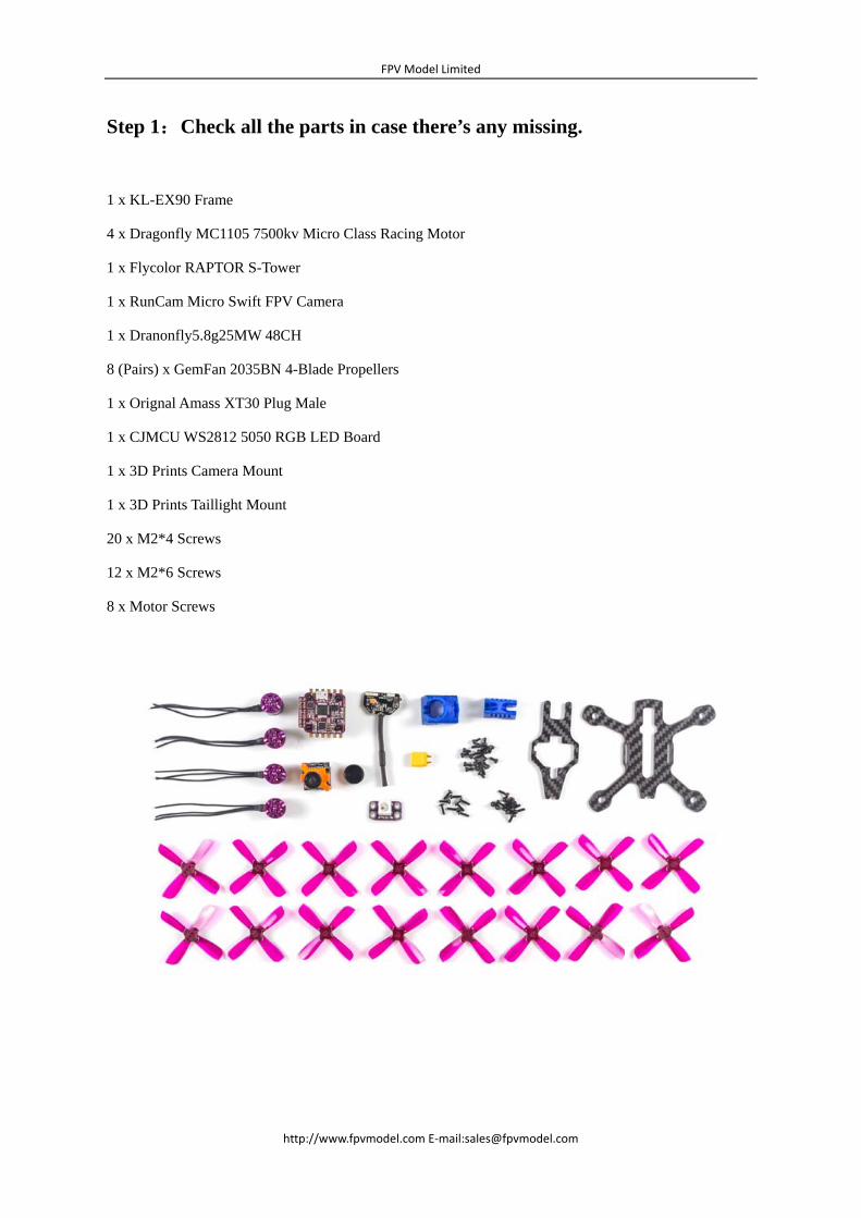
Step 1:Check all the parts in case there’s any missing.
1 x KL-EX90 Frame
4 x Dragonfly MC1105 7500kv Micro Class Racing Motor
1 x Flycolor RAPTOR S-Tower
1 x RunCam Micro Swift FPV Camera
1 x Dranonfly5.8g25MW 48CH
8 (Pairs) x GemFan 2035BN 4-Blade Propellers
1 x Orignal Amass XT30 Plug Male
1 x CJMCU WS2812 5050 RGB LED Board
1 x 3D Prints Camera Mount
1 x 3D Prints Taillight Mount
20 x M2*4 Screws
12 x M2*6 Screws
8 x Motor Screws

FPV Model Limited
http://www.fpvmodel.com E‐mail:[email protected]
Step 2:The wire lengths that you need to keep after cutting.
Please keep 35mm motor wires, including the heat shrinkable tubes, as well as 45mm 3-Pin camera wires, 40mm vTX wires, 35mm LED wires and 60mm power cables. See the pictures below for your reference.
Keep 35mm motor wires, including the heat shrinkable tubes.
FPV Model Limited
http://www.fpvmodel.com E‐mail:[email protected]
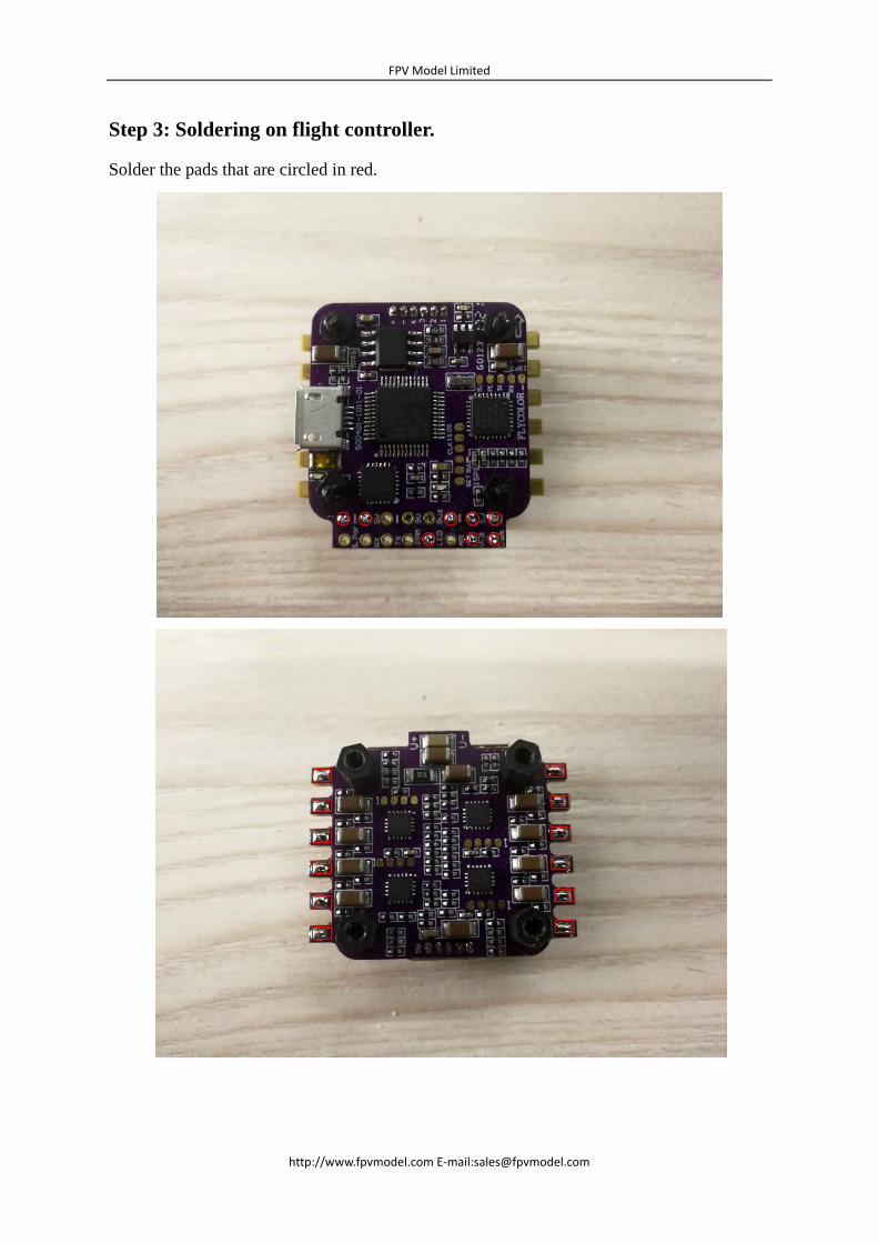
Step 3: Soldering on flight controller.
Solder the pads that are circled in red.

FPV Model Limited
http://www.fpvmodel.com E‐mail:[email protected]
Step 4: Solder the power cables.
Step 5: Solder the 3-Pin camera wires.
Recommend to solder the wires through the flight controller and esc, so as to avoid the
possible short circuit in hard crashes.
After soldering:
FPV Model Limited
http://www.fpvmodel.com E‐mail:[email protected]
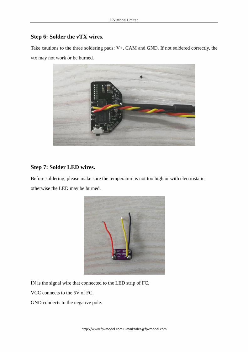
Step 6: Solder the vTX wires.
Take cautions to the three soldering pads: V+, CAM and GND. If not soldered correctly, the
vtx may not work or be burned.
Step 7: Solder LED wires.
Before soldering, please make sure the temperature is not too high or with electrostatic,
otherwise the LED may be burned.
IN is the signal wire that connected to the LED strip of FC.
VCC connects to the 5V of FC,
GND connects to the negative pole.
FPV Model Limited
http://www.fpvmodel.com E‐mail:[email protected]
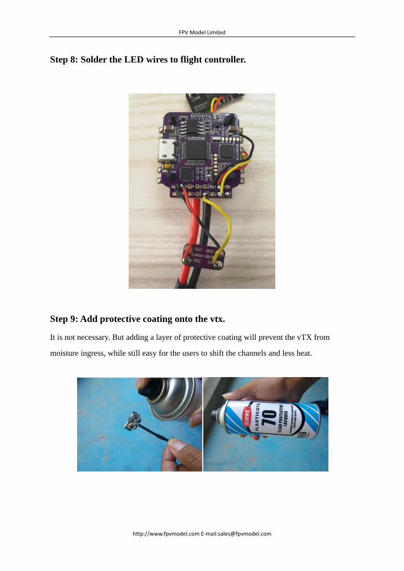
Step 8: Solder the LED wires to flight controller.
Step 9: Add protective coating onto the vtx.
It is not necessary. But adding a layer of protective coating will prevent the vTX from
moisture ingress, while still easy for the users to shift the channels and less heat.

FPV Model Limited
http://www.fpvmodel.com E‐mail:[email protected]
Step 10: Solder the vTX to flight controller
The vTX positive pole and camera use the same 5v pad.
Step 11: Solder the motor wires to ESC’s
You’ll just need to change the position of the three-phase of the first and fourth motors. The
second and third motors are soldered according to the sequence.

FPV Model Limited
http://www.fpvmodel.com E‐mail:[email protected]
Step 12:Install electronics onto the frame
Pay attention to the different types of screws.
M2*10 scres are used to secure 3D printed parts and the top & bottom plate.
M2*4 screws are used to secure the Dragonfly motors. Each motor needs 2 to 3 screws.
M2*6 nylon screws are used to secure the screws of Flycolor S-Tower and bottom plate.
The nylon strap is used to secure the VTX and top plate.
When fastening screws on the motor mount, please make sure the screw glue is added.

FPV Model Limited
http://www.fpvmodel.com E‐mail:[email protected]
Pay attention to the negative and positive of VTX. The side with LED needs to be facing up.
LED taillight is secured inside the slot of 3D printed part, no extra screw glue needed.

FPV Model Limited
http://www.fpvmodel.com E‐mail:[email protected]
Step 13: Installing the frame
Install the LED as below:
Step 1
Downlo
Basic s
Th
por
Ma
Sy
The m
configu
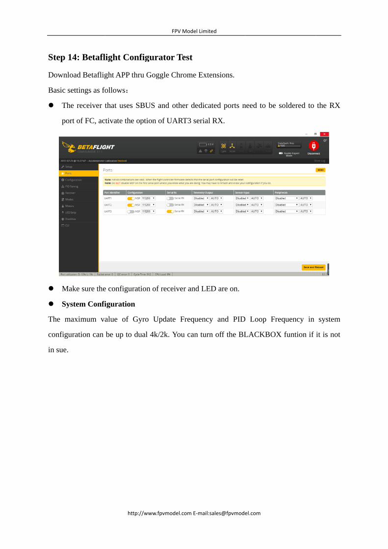
in sue.
14: Betafl
oad Betaflig
settings as fo
he receiver t
rt of FC, ac
ake sure the
stem Confi
maximum va
uration can
http:/
light Conf
ght APP thr
follows:
that uses SB
tivate the op
e configurat
iguration
alue of Gy
be up to du
FP
//www.fpvmod
figurator
ru Goggle C
BUS and o
ption of UA
ion of recei
yro Update
ual 4k/2k. Y
PV Model Limit
el.com E‐mail:s
Test
Chrome Exte
other dedica
ART3 serial
iver and LE
e Frequency
You can turn
ted
sales@fpvmode
ensions.
ated ports n
RX.
ED are on.
y and PID
n off the BL
el.com
need to be s
Loop Fre
LACKBOX
soldered to
equency in
X funtion if
the RX
system
it is not
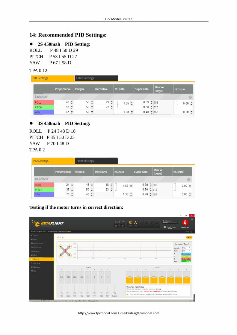
14: Re
2S ROLL PITCHYAW
TPA 0.
3S
ROLL PITCHYAW TPA 0.2
Testing
ecommen
450mah P 48 I 5
H P 53 I 55 P 67 I 5
12
450mah
P 24 I 48H P 35 I 50
P 70 I 48 2
g if the mot
http:/
nded PID
PID Settin50 D 29 5 D 27 8 D
PID Settin
8 D 18 D 23 D
tor turns in
FP
//www.fpvmod
Settings:
ng:
ng:
n correct di
PV Model Limit
el.com E‐mail:s
irection:
ted
FPV Model Limited
http://www.fpvmodel.com E‐mail:[email protected]
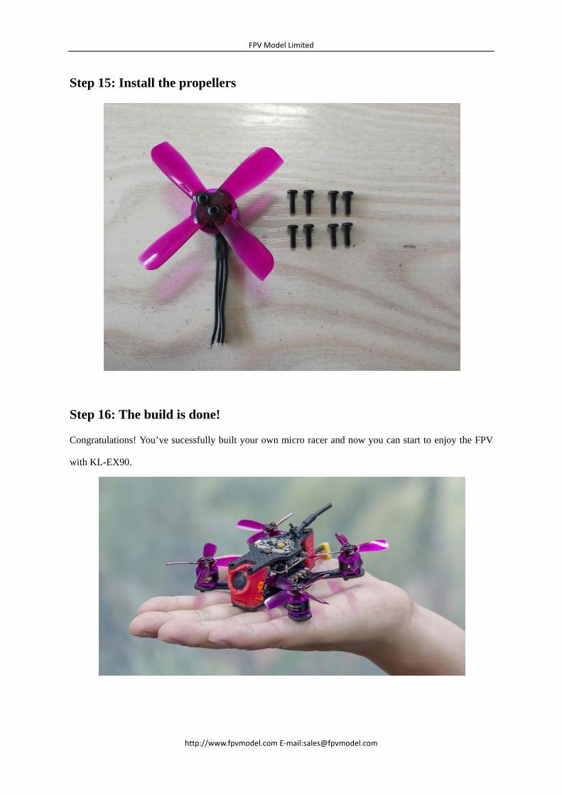
Step 15: Install the propellers
Step 16: The build is done!
Congratulations! You’ve sucessfully built your own micro racer and now you can start to enjoy the FPV
with KL-EX90.