![[2015] CCJ 15 (AJ) IN THE CARIBBEAN COURT OF ...2015] CCJ 15 (AJ) IN THE CARIBBEAN COURT OF JUSTICE Appellate Jurisdiction ON APPEAL FROM THE COURT OF APPEAL OF BELIZE CCJ Appeal No](https://static.fdocuments.in/doc/165x107/5b0a99507f8b9a99488c6d3c/2015-ccj-15-aj-in-the-caribbean-court-of-2015-ccj-15-aj-in-the-caribbean.jpg)
x. - core.ac.uk · Microwave Engineering ... TlONS OF CHARACTCRISTICS x. S. R~rkmizi utzd S. K....
38
Journal of the Indian Institute of Science, Bangalore 560 012, India [Section A: Engineering and Technotogy] Jrmrulry ! 980 CONTENTS ORIGINAL PAPERS Pri~e Microwave Engineering COSINU~OIDAI,LY MODULATELI SURFA.CE WAVE STRU<:T~~ES-NIIMERICAL CAI.C[~LA- TlONS OF CHARACTCRISTICS x. S. R~rkmizi utzd S. K. C/rat/ccj~~r SHORT COMMUNICATION Chcrnica' Engineering AM BQ~JA'PION OF STATE FOR SOME G A S U A{. .N. Clr~~~l,oshchura ~ t d D. N. S~,,shudri BOOK REVIEWS
Transcript of x. - core.ac.uk · Microwave Engineering ... TlONS OF CHARACTCRISTICS x. S. R~rkmizi utzd S. K....
Journal of the Indian Institute of Science, Bangalore 560 012, India
[Section A : Engineering and Technotogy]
Jrmrulry ! 980
CONTENTS
ORIGINAL PAPERS Pri~e
Microwave Engineering
COSINU~OIDAI,LY MODULATELI SURFA.CE WAVE STRU<:T~~ES-NIIMERICAL CAI.C[~LA- TlONS OF CHARACTCRISTICS x. S. R~rkmizi utzd S . K. C/rat/ccj~~r
SHORT COMMUNICATION
Chcrnica' Engineering
AM BQ~JA'PION OF STATE FOR SOME GASU A{. .N. Clr~~~l,oshchura ~ t d D. N. S~,,shudri
BOOK REVIEWS

hlrriusLr~pr, 41r,:~!,l b~ ici tmi;Lrli .iz:J aii::<ti I t , i i,i\ii>i ir.:r i i .P , la,$::: :)j :,.! ~ r : t i , r r a 4
w o copies rin;t~lil rn l~~r i~r to l . 'l'lac v i r 4rrt '~i~f ;u: njr.! ?.,.!-'.i. 'r.ci\i: MZ':I ' cs .1:,!.
, ~ > ~ g j u <,n Jl! t$,"r >i,Itb. '1 I*< ,>.,i:c, !,hWI4 be L, lP ,< , u::\c'> t l . ! i > A !<.>! ,4 ,w., b . t l !i % ~ , f " f i ~ % I .
'1hC Titk l',~gt ~ ! m l d ~ I I I . L ~ I I t h : d ! o ~ i l v . : ( i j (hC ricIf., ~ 1 ~ i ~ I ) ~tj,,t)!~i !v lwei id ',&,t$m ! $ ; ~ l n ~4 ,* , w t : , ~ ! s ~ ~ ~ I ,: ::8;.,u,!q,
($j) the ZI.I~I><S <>i the , u~ twr ( : , ) .d tlw , Iqu?t i i lcv i~[~~ \~i:vsr t!w ui,t i U J S ~ . ~ c t i d w r ~ { j i ; ) .t fd"tn<>t~, \>!El! prCX23r . d ~ l 8 ~ \ ! . U! $!L%' . > t ! t 1 8 k < ; ' ' , t f , , l ! ! * Z ~ : 3 f f!v:>t l!LC It! , (its) on absrrnrt mat crceeding .W noid.;, a.llirii ,.!1<111l.! \ : i : ~ t : i r , , ~ t i i ti?: ~:s~ttc~i. . j <ma:,; ~ r i ihr paper xnd iuclnLIe the sigtifiwc ~ c x h , ; t c ) h q GCYA I W i n 'm.aa .d ~ n I ~ ~ : t n U + d u : d l m . d ; (',i) dle m j o i &cipline to ui.i;irlz the > ~ t ~ i c iritn!g, It .r p ~ ~ ; ~ ~ , s 5 - : a.i.:rri~ 8: : .4id (zji;i a r ~ m ; i ~ ~ ~ uth, rtm cwcedii$$ ?I1 'li.bl.Nl~'r~
,& .l'c>r sllu,liJ Lcgi,] ,,t> I,.,,<C :. !\ !S )%,,.:~:,,l-:? , !:,i .'+> .I:, I? 1 2%. ,.:!l-:"lb:
~cct io j~s \yitll ~~i i t ,~bj<: l>t~.li!>~,v , 1x1, .A%: ! I \ , I U , : A 5 ti, ,.'*, .' ! SPY'$!l5il l % I .
A B ~ ~ , ~ S ( , ~ : ~ ~ I . N T , :. T111,0~(lillc,,il. A S A ~ . ~ ' & I ~ . . . .. t o w i i ..:: . ?. ,>,r h*rmi 1 lrrl ,..! 4 1 -
B~.~~~~~~ rhoi,~,i irUijwcd :la Imi) I ~ I :lac : h i k: A,+! tc :+;.n.ci :.; & :&n: ;tc pl.~cts, 1::. ' ' ihrltm &,d; i d m e , w r ~ d , , ," , A h.1 v! t i t ? w:~utc:~:s A , : l ~ : kw t y ( n ~ in h h l e qucing on a rip.mte rbcut in thi urdci :,I tiair i.ict.rrts e t r i rli; cr?! 2 z . i .ii,i.t: v.1
~r rhc end of rhc piper. 'The tclciemx: d i w l J hr, j i r t r , r i ititit :,;I1 ic : i r i r .i; :!w r..:r.-..i::., cr:impio :
(3) R.m&i,hm ?+.i&~, C;. 8 ~ ~ 1 N&iu, 1'. R. bdW1W a ~ i t . . ; l ~ ~ ~~~~~~y t ikc; x x ! ~ h x i n tltr pernce of toinidbr~~s, I W C . lnd~ln .led. b r r . . 1'1 h. 6iA. b i i I I , . .
( 8 ) Hi&", A,, L & w ~ i r z ~ zbI~&mjL~r~ I%>,, V d . i , i h. 132. ' * I - la!!, !':rwi..c, Hnli, New Jersey.
(9) C;nngJhrrriah, T., Tbo <;barxdmit:ir of Seilr?u.dr,J I:ir:i., l!I:.l, ( f r .". pii. 25-27 Thesir (unpublisheJ), Indian Invritt~cc ut bfivarr.
Tnbics shouiii be incluilcci ori!y xi er$crrii~i. l'lici. h.:il.: it: .::;:th:ri : o i q c i . r ! i - ir wirh Arabic n~tmc.rils and rypcd on rci)arzrc rlmerr. Ilsets t.<!>!c . E t . d i . tm:.i,o A .ic%riy:Lrc title.
Fjgilrcs should be drawn nirh h i i d r i ink on #:in1 rrdruy: !;,pi. I r 2 8 r:s.ali , : i ;p;.rri irc chat the lines and iorrcriny nre sullicienlly h l i ro permi :a io~ tw. r~ r u titu ].,:ilu! : ;P .
Ea.h arigiwal drnwiag should bc ncturnpmirii bg 1x0 umnunii prior+. r,r X c p s rcyics. 1 % ~ 6g.m captions should he typed on n aeprrate p.rgr.
Mathematical Symbols should be iiicntified wnh vcnil! #:n :hc ir::r.iu:.d d r a4tg;ii . Standard mathematicnl notations s h u u l bc adhemi m. Plcrre ,ii>trr:;rl;irli bcr:vrcn %A)" and "kappa", "ell" and "one" and other similsr symbolr likely ro ~iurc .onfurir;rr.
Abbreviations, such as ez., ai 51 snd LC., t i n he used, if rmii+no~lur,l ~ l r b r ~ u t r r i ~ ~ d
or acronyms are used they should be Expleincd whrrc t h q npperr in :Ilc rtxr.
Gallry Prools will be sent to the hbt author tor iclrrcction. ?lie prnols %hehou~j k carefully scrutinized and mrtecrcd and returned whbin ;? ;.ourJ of tcmiri.
Reprints can be bad at a nominal cost, il tbcy ure arilcr?d .;it tile ;ie;i r.l iriiitnlr>i: the corrected ptoofs. Fifw reprirrrs are givcn frce 01 rh2ri;c ii &ere iu *,ni. iri i t l~xrr ail.i tor) reprints if there is more than one author.
The maQUsckXs will be returned bsik if thc zhnvc irirrrt,,ih~:1~ nri {i,i:dsc,'. The manuscripts should be sent to Ihr & h i , loarnai of tb. jr;~ija ~ , ~ ! ; i ~ * ; ~ ~~ i~ .~~ . , ,
C/o L1.s~. I.ibrar~, B~angalorc 560012. All further :orr<spo:idencc rogarjjl,i: ~ 1 , ~ r:,.!r,::rcri;.r. should be addressed to The Editor.

J. Indian Inst. Sci. 6; (A), Jan. 1980, Pjx 1-36 @I Printed in 1nd1.i
Cosinusoidally modulated surface wave structures-numerical calcuIations of cliaaracteristics
T. S. RUKMlNl AND S. K. CHA'r'TEKJEE Departtitcnt of tlcctncal Co~ninun~cation Enginwring, Indian institute of Sci~ncc, Bangalore 560 012, India
Abstract
Results of con~putcr-aided c;lloubtions for Ithc powcr carried by surface waves, atlentation, swface impedance and tho cikcts of nwdulatiotl index on t t c radial lield dccay, spatial bai-monics, otc., arc reported. Stability of surfucc wavc modes confu'tncd by cxperinlcnlis disct~ssod with thc help of stabi- lity charts drawn for thc rno.lulatcd structures.
Key words : Molulated surfuco w~vo st~cturcs, stability of surfacc wave rnodos.
1. Introduction
The paper prescnts a report on the nutnerical computations of the characteristics for cosinusoidally spatially modulated circular cylindrical metallic corrugated structures excited in E, mode based on the theoretical analysis by Chatterjee et u P 3 . It is shown that spatially modulated surface wave strwturcs with low values of modolation index (6 <: I) can support more strongly bowd surface waves than uniformly corrugated surfase wave structures.
2. Equivalent dielectric constant E~
The corrugated region for an uniformly corrugated rod excited in g wave is simalated, as a homogeneous dieleztrio region of cqnivalent dielectric constant eo = f (s, b, a) where s, b and a denote respectively the spacing between any two adjacent discs, radius of d i m and radius of the central supporting rod. Since i t has been proveds that the relative amplitndes (A,) of Floquer harmoniorsatisfy Lhe inequality relation A, ( m f a)/ Ao (m = 0) < 1, therefore, ea for the fmdamentaI mode (m = 0) is calculated by using the relation

where, tilt. p h a ~ e co i~ \u~n t !I,, fur the Sitndante~ii;il mudc i' itctcr~l>inod l'rcriil rhc rolution of tlw following equi~tion'
Figure I ~ h o w s that
(iii) For a groove deplh % ?d,,/?, G" ilpproachch the v:tluc crl ' i r n t r ? which i s the villuc (hr the externnl n~cdiu~n (air). Thiz implies (hat 11 rnodiliad ' Harms-Gowhau ' line approaches ' Sommerl'eltl ' surf;ue w;we line when the gruovc depth for r spatially modulated line app~owhes tho valuo ol' inkryriil rrtutriple (rr - 1,2,3.. .) of half wavelength (1.,,/2).
(iv) It is evident that increase of 2:" i s associatccf witlr inclxasc <11' ji,,. l'l;ereli~re. .2
slr~rciure with highcr values of sat1 supporl nlorc strongly bound w r f a x wave which is in conformity with the case of Harms-Goubat~ line.
(v) co in-rwses w;Lh k,, i.c., with increasing frcq~icncy oS crcitatiun Ibr ; ~ l l o d values o f b and s. Hence, for it surhce wave structure w i t h a n~odilird s u r f m more strongly hot~nd surrace wave can be suivported with inae:iaing frequency. This is also in conformity with the conventional W - 6 . line.
Hence, it may be concluded that the evolvction of tho equivalent Jiciwtric cOnLept f ~ r the corrugated region for the purpose of anrtlysis is justified.
3. Modulation of cu
Since go +f(& b) with the parameter a held constant, spatial or depth moduk~tion is achieved by varying s or b respectively and keeping tho other parameter constant. 111 lhis case, spatial cosinuroidal modulation is studied.
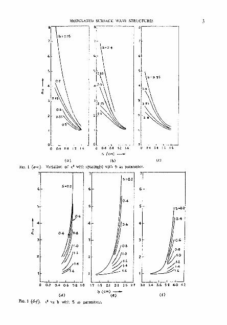
FIG. 1 (40. r " w b with S as panimetcr.

where the modulation index d ir delincd by
4. Radial propagation constants
Using the €allowing mixed boundary condition%

Fro. 2 u. Spacine vs 2dIL and 6, vo 2m:IL far cam 3. rb - 2.914, b = 0.3 cm, S = 2-05 cm, 9 = 0.2 m.


MOWCAPEII SURFACE WAVE STRUCTURES 7
and appropriate field components for the two media the following characteristic equa- tion"~ ohtained
Fro. 3 a. Variation of kt and k, with 6 at z P. 0 with to as parameter.

The solution of (5) will1
kg - kr + k3, [I - t (z) ]
yields thc values of k , and k, asf'(d) for fixed voltres of re (Fig. 3), st : -. 0. Figure4 shows t'le variation of k , and k , at different Iw:~tionc of the .;!ruulure ever a half period. Figure 5 shows a comparison bctwecn k t , and k,, (p: order ol' mode.;) between two successive higher order modes.
The following observations may be made regayding k , nnd k , :
(i) k, > k , for [he slrirctwe with .$ -: 2.0 over I ~ C whole r a n g of (5 hut for struc- tures will1 c0 := 1.062, 1.293 and 1.323, k, :?. k, over only n linlited range of 8.
(ii) k , and I (z) and hense /l are slowly varying functiotln o l '2n~!1~ . i.c.. the locations along the cell length 2.
(iii) The different natnre of variatiolt or k , and k, with Zrrzjl: far the two modes signifies that the two modes behave differently with regard to rndial field decay at different locations of the stntctups,
. . ,

MODULATED SURFACE WAVE STRIJCTURES
I
Plo. 4s. Variation of kt . k, witlt 8 for cu - 1.323 o w lie period InzlL
3.0 " 0 t 1.0 - -- 2.0 - 3.0
ZTTZ/L - PKI. 4 6. Variatlon of k,, k, with S ror - 1,063 over the period I n j L .
(iv) The constants k,,, ke, and /)6 i n the two media forp modes arc related as follows: fl; = k':,, -+ k t (7) First medium (med. 1)
and /3; =- Gkf, -k kt c ( z ) (8) Swond (modula~ed) medium (med. 2).
The equalities k,, = k,,, k,, - k,, at LI i=i 2.35 I~/2f l signify that the two modes beooma indistinguishah10 (8' = P,).

(v) The equality k,, -= k,, signifies that
which means that fit > j, since 6 (2) > I , or in other words. I*,, ..: 11,~. Hence, the higher order mode is more slrongly hound and consequenrly its rare of radial decay is faster than that of the first mode.
(vi) The equality kcT = k , , = k,* signifies not only the indi.;tinguisl~~hiliq of the two modes in medium 1 but also that I*", < v,,.
(vii) The phenolnenon of mode crossing observad in some cases ir psdb ly due to coupling of modes ar'ising due to spatial rnattuistion of cornkptionq.

hfODUl.ATED SURFACE WAVE STRUCTURES 11
5. Phase eonstant (/?)
The problem of the propagitioa or E , wave in spatially modulated surface wave struc- turesisfnrnlulated in thc form of Hill's eqoation, rhe solt!tinn of which yield5 the following relation'
where the dcterlni nanl
zfi sin"
and involves 0, (11 - (),I ,2, . . . ) where
Where the length of a cell L =, f (b , d3) which can he determined from Fig. 2. The variation of 0. (up to IZ -.; 4) with respect to 8 is shown in Fig. 6 . The variation of 9 [O] with 6 i s shown in Fig. 7.
6. Radial field distributions
The field components in tho two media ere given bys
Med 1 : b < p . = ~

Fro. 6 (u). Variation of N,, with S. with r'l as Ro. 6 (1)). Variaticnl of Nt wit11 8. with, en
pnrameter. parameter..
Ep2 = - Aq [ ll (k@) -b. u@) K, (k@)1 (Ill KO (kg4 i
Where x and x1 involve the Fourier gap coeflicients c. (P).
The field distributions (E: and Hg withp) in both the media are shown in Fig. 8 an1 9. The following condusions are of internst.
(i) The radial field de:ay in the outside medium for modulated (6 > 0) strUctU:ei is h t e r than for an unirorm (6 .- 0) slrucure. Hence rho surface wave is man tigitly bound in the case of.modulated stnwtures with low modulation indo compared Lo the case of an uniform stmcture.
(ii) The end-fire property of surface wava modulated atnrctures d e w s not only on a proper choice of 6 but also of L. The fast that better end-fire property m n k atlained by slow rate of variation of s, i.c,., c ( 2 ) is also supported by Billstram',
(iii) The higher modas de:ay faster in med. 1 than the lower order modes, since > 4 , > k,,. The greater consontration of energy towards the interface lead to greater Joulean heat loss for higher or&r modes b n tho &st order mode. Conrequently, the first order mode will be guided to a longer distance along the stm-tnre. Heme for a finita length modlrlated structure, the end-fire radia. lion will consist mainly of the first order mode.

& MODULATED SURI:ACI: WAVE STRUCTURTS
7. Fourier gap coefficients
The Fourier gap cooficicicnts c, Ibr d fo r rn ly corrugated rod is gwen by3
where 1 is the length of a period and n : 0, :+ 1 , 2. & 3 order of forward (-I-) and backward (-) spaee harmonics. F,, (k ,p ) /F , (k&) takes into acco~!nt the natL!re of the geld variation in the radial direction. For a particular valne of c,, -- f (b,,s/2). I t is found that over the region &s/2 -;. 0 to 0.4 c, is a very slowly varying fmstion of J.
Hence, in the ease of the spatially modulated structure, the variation of c, may be consi- dered to be inappreciably small. Hence, c, ( B ) fbr rhe modulated structure may be considered to ha the same as c, in the case of uniform stnr.cti!re withont introducing any appreciable error, provided 8 is small.

l'hc histogram or e,,,,, arc shown in Fig. lo. I[ i a irbacrvetl ih;rt
(i) Tor slructrtres with c" - 1 . 53 1, 1.408 sn3 1. 179. I.+, En 4 O)!c,, ;. I whereas, for slructures with cU = 1.062, 1'293, 1, $23 and I . 144 i. , ' - c,,,.
(ii) All a*, ( i t+ 0) in tho caw ul' struoturcs with GO .. 1.53 I . I .JOX :n~d 1.179 are
f'(cm) - FIG. 8 (a). H+ vs p for 4 = 1.293 in medium 1.

8. Power flow in modulated strucfures
The power Row outside (P;) and inside ( IJ:) the t l~od~!l;wl ~ncdiittn in the z-direction are given by the k)lluwing ralniiotn"

1.0
MED I
t Ez
0 0.1 0.4 "0.6 0.6 1.0 1.2 1.4 1.6 1.8 2

MED I1
where

FIG. 9 (a). H, us p for eQ = 1,ObZ.


MOUULATEU SLIRFNC W A V E STRUCTURES
and
m
- 2 c; iQ) sin ii f I ; , (8) sin 0 ] i - ( 1 -- h c w k) L ,
m-m n--x
m 2 c l y % [ .; Cii,cos u 8 sin i 2 iR (4) sin 0 -l- c n 0 L "-- m n r .OO wl) r.-..WJ 1
- 2 cm (j3j q: \in 0 $ i,,, ( p ) sin 0 , , r o O I, -02 I
Since 8, is a slowly varying rmction or z, it doei not vary signiiicnntly over a period L. Hence, c,(j3) docs not vary significantly over a period L. The order of smallness of variation may be estimated as (WKUJ approximation).
d" 4 c. d"V4 _ c, ,"here -:+ & &* q > L" dp- ' dj3
dc and hence -$ can be replaced by 5' which is equivalent to replaciny $: by 2 L
'he relative intewitie~ of spatial hhnrcnonirs I,,, (nf O)/fe for structures with different valw of @ and 6 shown in Fig. I I in the form of his!ograms lead to the following conclt!sions.
(i) f:. (nZ O)/f, c 1 for all structures. (ii) For all structrrrm with anyvalue of A$.., >,f,,, but f , . (n , I ) sf-, (n s 1) for
the corresponding values of n.
(lii) For a structure with s particular value of 8. S has very little infilrence on f* (n# 0)if. within the rnnge of S - 0.02 to 6 = 0.1,

Frc. 11. Hi;Lo~ams of 1:-c relative iniensiticc of spaiiH1 hamni t s f :i- ( rz f -O)[ fw

The or the I - n t h Or /'" 'I"",; a i l l 1 r c i j r e~~ l to tT and I n -'I, \vllere PI I-- p! .;. pJ, presented i n Fig. I ? ~;lu'ii ili:ir
(i) P:/PzT = I ' ( ') cul l1 C L ! ~ tLi:lWid\ im t l ~ c . i : l~wcd valtreb oi' /?, i.r.. t l ~ c s t a b i l i t y oi' modei.
(ii) P:/PT tcnil.; to iwrc:~v;i: :IS , i -+ 1). 111 ~ l l i ~ i . \\o[.di I I I C Z < I ~ \ C ~ ~ ! L ' I ~ C C of mndulat- ing ~ h c \.r,!cil~ru i.. 10 .~t!hi iain moi-e p m c r io f l o ~ in ihv iiiodr~iatzd mcdirm, thus ensuring a marc ii!:htiy h i ~ t ~ n d s i ! ~ f x c w:i\e.
Fro. 12 (i,) P?/PF v* ?rz/l, for r* ! .??t. 1'1u. I3 (171. klb :old i,.h 1 s l n z ! for co - 1 .5?3. -- I \ t roof. - - - 2nd T L ~ . l ~ t root, .- 2nd root.

where


25 T. S. RCTEhllNL AND S. 1;. OIIATTER.IEE
Fro. 12 (it). X,h vs 2 4 for so - 1.062 (I st root)

MOI>ULATEI) SURFACE WAVE STRWCTLJRES 27
10. Attenuation constant
K: ( I - b) $ L-
1 lk2a) PI (k&l - 1 . kz) KL (@I]
and
(i) As 6 -t 0, i.e., &, + &,, i.e., the modulated structure tends towards a miform structure, a is driermined with the understanding thaL the transverse propagation con- stants kcL and k, and the axial propagation constant have the values corresponding to the values of a structure with uniform spacing but with the same values or h and a.
(ii) As b + u but (b - a) # 0, i ~ . , for small depth ol" corrugation, the terms illvolvins (b - a)lk, in (16) can be neglected and hence a reduces to

28 T. S. RUKMlNl AXD S. K. CIIATTBRIEE
I 0.02j
0 1 2 3 4 5 6 7 8
P ~ / L -- Frc. 1 3 (b). a vs Zm/L for d~ffcient 8s for ra = 1.513.
(I) The variation of a vs 2nzIL (Fig. 13) shows that a,,, - a,,,,, is much less for lower valLles of 8 = 0-02, 0.04 than for higher ~ a l u e s of 6.
(ii) a,,,, for all values of 6 is attained at 2nzlL = n.
(iii) a,,(6+ 0) (Table I) calculated by considering values of a a t 1116th interval over one period is greater than e (6 = 0).
(iv) a,, (6 # 0) > a (6 = 0) is justified since
5 * ( 8 = 0 ) > $ $ % ( 6 > 0 ) , Pz ..- The outside mediem, being air, islo?sless. Hence the loss for the guided wave is contribnted by only the. physical properties of the moduiatec. medium.
(v) For shallow grooved strtrctures a vr 2m/L (Fig. 14) shows that (Table 11) a,, - 0
;s higher compared to that given in Table I,

MODULATEV SURbAC6 WAVE STRUCTURES
Table 11
a,, - a for shallow grooved structures
io = 1 0662 --
6 0.02 0.04 0.06 0-08 0.1
~e = 1,523 -- o,,, - R 0.7931 0.7927 0.7915 0.7901 0,7891
Since the cormgated line approaches Solnmerfeld line as b a, ohntic dissipation giving rise to Jonle heat loss is mainly responsible (radiation loss being l~eglected in both the cases) for supporting surface waves, i t is reasonable to expect that
a(shallow grooved line) > u (b ;. a)
b - a
11. Surfate impedince
The real and iinaginary park of sarface impedance are givcn in Lhe followiilg dimension- l e s form"

0 . 4 1 I
0 1 2 3 4 5 # _d
6 7 8
Z T T Z / L - RG. 14 (b) , a vs ?m/L for diifeccnt 6s for E" 1.523.
and
2nh X, -. , = - [qb arc tan + b,b lo O 89 (a: b' + i; L ? ) ~ I U,b (186)
wherc k, = a, - ib, and 6, = 9 a,
The radial lield de:ay and atlcnuation depend respectively on X: and R, which a.re intllen<ed by 6. Figure 15 provides design data for developing a strwture characte- rised by a rapid radial Reld deay and with minimnm attenuation. It is desirable to have hi.gl.l pos!tive sarface reactance findi~xtive) andlow surra~e res:stance X, = 123 R, - Ke(ZJ are /'(a, 8) and losation (2) along the structure, hcnce ~ h c average values are plotted in Pig. 15. The average values have been calculated bq coneidcring thc value? of the paTanleterS at 1/16 interval over a whole period,

MODULATED SURFACE WAVE STRUCTURES 31
FIG. 15 (a-d) (a) R, (,,,lZo vs 8 for 4 = 1.062 and ao = 1.523. (6) a,, nkm vs 8 for an 5 1.523 and so = 1.062; (c) X,,,,,/Zo vs 6 for 8 = 1.062 and to = 1.523; (d ) Z,(,,,/Z, vs 8 for @ = 1.062.
We conclude from Fig. 15 that
(i) For structure with €0 = 1.062, the design shonld be for 6 = 0.08 or 0 .1 so that high rate of radial field decay with low attenuation can be obtained.
(ii) For strircture with r = 1.062, the design should be for 6 = 0.06 or 0.1.
12. Measurement of radial field decay
Radial field decay for several modulated and a uniform corrugated structmes was measured with a monopole probe (Fig. 16) and the results are compared with theory (Fig. 17). In the second and fourth illustrations of Fig. 17, the experimental (00) and theoretical curve coincide for 6 = 0, whereas, for 6 = 0'04 there is a slight divergence between the two curves.
We conclude, that for modulated structures, the rate of radial field decay is faster than for uniform structure.

32 T. S. RUKMINI AND S. K. C H A ~ E R I E B
FIG. 16. Photogiaph _. - of the structure.
13. Stability of the surface wave mode
The stability charts (Fig. 18) for structures wilh eo = 1,062 for S = 0'08 and 0.25 have been prepared with ,5 as a parameter by irsing the equation (10) with the aid of a 360 IBM computer. (The Flow Chart is not reported).
The stable solutions corresponding to modulated propagating waves are associated with the 8-values bounded axordug to the following inequality relation
The regions (hatched) which do not satisfy (20) correspond to the unstable solutions of (LO). The unstable solutions are asso-iated with the non-propagating or damped waves. The values of j are real within the shaded regions (unshaded), whereas they are complex within the unstable regions. As 8 = f (&,8) and c0 = f (s, b, a) and 6 determines the propagating or non-propagating nature of waves, the stability charts which determine k, can be used for the design of proper modulated structures which support strongly bound surfase waves.
The location of the mode supported by the experimental structure en = 1.062, 8 = 0.08 is shown in Fig. 18 (a). The experimental point @lies within the unshaded regm ,5 = 3 and j = 4, thus indicating that the mode supported by the structure is stable. It is found that the modes snp~orted by other experimental structures with e , = 1.062 and S = 0.06, 0.04 and 0.1 also lie in the stable regions of stability charts which are not reported.
Figure 18 (b) shows stability diagrams for the strmture with so = 1.062 and S = 0.25. Similarly, the stability diagrams have also been drawn for other structnres with b = 0'08 and 0.25 for which no experimental structures were made.

MODULATED SURFACE WAVI? STRUCTURES
The following remarks regarding the stability charts are or interest.
(i) The curves separating the stable and unstable regions in some cases cross over each other, for example, near the points (I, = 440, 480, 580, eic. (Fig. 18 (a)) where
tii) The area of the stable regions increase as the valw for /I increases. There is also a tendency for the separation to inxease between two adjacent cross-over points as p increases. As a consequence of increase in p, the waves become


more strongly bound. Hence, it may be said, that the structure for which the nrm is no st strongly bound will exhibit the largest area of stable region with widely separated cross-over points in the stability chart. Hence, the usefulness 01' the stability chart for desigoing a space modulated structure is obvious.
14. Basic assumptions and their limitations
The iheorotlcal der~vat~on of 11 for space modulated str~tctures 1s based on the follow~ng assumption6.
(i) The nonuniforn~ly corrugated metallic structure is considered as a conductor coaled with a dielectric whose dielectric coostant varies cosinusoidally in the direction of propagation.
(ii) 8 : 1. This helps in truncating Iheseries for 0, (11 =; 1,2, . . .) which k involved in 9 [01 and hence for B.
(ii) For deriving the profile equation for the design of a practical structure, small and large argumenl approximations Tor the Bessel fnnclions have been intro- duced from practical considerations. This may impose some limitations on the accuracy of the resvlts. But considerjng the accuracy which can be attained, in practice, in fabricating the structure it is considered that the argument approximations are valid for all practical purposes.
(iv) The ain~ulated dielectric medium is considered lossless in deriving 8.
(c) I;n deriving the magnitudes of the spatial harmonics, 111 and hence the Fourier gap coefficients emu) is considered to be a slowly vacyu~g function over a period of tho modulatiol~ cycle, which leads to sinlplification of the expression forf, (/I).
(vi) The coating thickness of the equivalent dielectric is considered tke sane as (b - 0).
(vii) In deriving Po, the field outside the slructurc is considered to be pure svrfaie wave iield and the effect of diffraction is ignored. The assumption, however, is justified in view of ihe higher value of /3, and hence a lower value for v,. This is conferred by the experimental measurement of radial field decay.
15. Conclusious
(1) Cosinusoidal lnodulation of spacing belwecu discs of circular cylindrical metallic corrugated structures lead to more strongly bound stable surface waves.
(ii) Corrugated metallic structures may be considered as equivalent to a conductor coated with equivalent dielectric whose dielectric constant is a function of the spacing between discs, radius of ihe discs and radius of the central supporlinp rod.

36 T, S. RUKMINI AND S. K. CHATTERJEE
(iii) Th'e corrugated modulated region provides inductive reactance which helps in snmorting surface waves.
(iv) The at:enuation constant decreases with increase in the value of 6.
(.v) The power flow outside the modulated structure with respect to the total poher flow dexcases with increasing 6. . . . .-
... ...-. . . . . < - .- 15. Acknowledgement
l t 1; a ?:ea; !re LO a-knowledge the invalnable suggestions by Dr. James R. Wait (ESSA~;;'NOAA), 'Monitor PL-480 ~ r o ~ r a m c n e (Contract-E-262-69 (N), i969) and the fi&n(tal &i.is?an-,e at the initial stages of the problem by th;e PL-480 authorities.
. O x grateful thanks are dso to Prof. -(Mrs.). R. Ehatterjee, Chairman, Department of E!e-trkal Communi.cation Engineering, for encouragement and -helpful discussions.
. . . , . . . . References
!. CHATTWEE, S. K., . . Propagation of E, waye in modulated artificial dielectric media, RUKMINI, T. S. AND, . ..-. J. Indian Inst. Sci., 1977, 59 (A), 225-45. CHATTERIEE, R.
2. CHATTLRJEB, S. K. AND Sirnulatioil of cosinusoidally modulated dielectric medium by RUKMINI; T: S. - artificial dielectric at microwave frequelkiks, J: Indian Inst Sci.,
1978, 60 (A), 47-64.
3. CHAT~BWE~, S. K.; Surface waves in a nonunlformly conugated cylindrical metdlic RUK~WI, T. S. AND StNCtUre, J. Indiun Inst. Sci., 1978, 60(A), 119-134. CHATTKRIEE, R.
d;. BILLSTR~M, 0. E.M. Theow and ~nknnas, Editod by E. C. Jordan, Pergarnon Press, London, 1963, p . 875.


![[2013] CCJ 5 (AJ) - United Nations · [2013] CCJ 5 (AJ) IN THE ... CCJ Appeal No CV 7 of 2012 BZ Civil Appeal No 4 of 2011 BETWEEN BCB HOLDINGS LIMITED ... Mr Michael Young QC, ...](https://static.fdocuments.in/doc/165x107/5ac0a0b87f8b9aca388c1f46/2013-ccj-5-aj-united-2013-ccj-5-aj-in-the-ccj-appeal-no-cv-7-of-2012.jpg)
![[2018] CCJ 20 (AJ) IN THE CARIBBEAN COURT OF JUSTICE ... · [2018] CCJ 20 (AJ) Background to the Appeal Against Conviction [4] On Independence Day, 30th November 2009, the deceased,](https://static.fdocuments.in/doc/165x107/5eabeb69ad0ae6720e6f22af/2018-ccj-20-aj-in-the-caribbean-court-of-justice-2018-ccj-20-aj-background.jpg)
