Wyler Technical Document
100
INTRODUCTION INTRODUCTION to INCLINATION MEASUREMENT to INCLINATION MEASUREMENT INCLINATION MEASUREMENT INCLINATION MEASUREMENT Introduction in INCLINATION MEASUREMENT
-
Upload
leonelarias -
Category
Documents
-
view
309 -
download
9
Transcript of Wyler Technical Document

INTRODUCTION INTRODUCTION to
INCLINATION MEASUREMENTto
INCLINATION MEASUREMENTINCLINATION MEASUREMENTINCLINATION MEASUREMENT
Introduction in INCLINATION MEASUREMENT

P ibl li ti ith i li ti i i t tP ibl li ti ith i li ti i i t tPossible applications with inclination measuring instrumentsPossible applications with inclination measuring instruments
STRAIGHTNESSSTRAIGHTNESS INCLINATIONINCLINATION RECTANGULARITYRECTANGULARITYSTRAIGHTNESSGERADHEIT
STRAIGHTNESSGERADHEIT
INCLINATIONNEIGUNG
INCLINATIONNEIGUNG
RECTANGULARITYRECHTWINKLIGKEITRECTANGULARITY
RECHTWINKLIGKEIT
PARALLELISMPARALLELITÄTPARALLELISMPARALLELITÄT
FLATNESSEBENHEITFLATNESSEBENHEIT
MONITORINGÜBERWACHUNG
MONITORINGÜBERWACHUNG
Applications

VialsPrecision Spirit Levels for small angles
VialsPrecision Spirit Levels for small angles
Vi l / CLINOMETERVi l / CLINOMETER0 Vials / CLINOMETERAdjustable Precision Spirit Levels for anglesup to 360 degrees (CLINOMETERS)
Vials / CLINOMETERAdjustable Precision Spirit Levels for anglesup to 360 degrees (CLINOMETERS)
0
180
Capacitive systemsAnalogue systems
MINILEVEL / LEVELTRONIC / LEVELMATIC
Capacitive systemsAnalogue systems
MINILEVEL / LEVELTRONIC / LEVELMATIC/ O C / CDigital systems
ZEROTRONIC / CLINOTRONIC
/ O C / CDigital systems
ZEROTRONIC / CLINOTRONICC1 C2
Inductive systeme with pendulumsAnalogue systems
NIVELTRONIC
Inductive systeme with pendulumsAnalogue systems
NIVELTRONICDigital systems
ZEROMATIC 50Digital systems
ZEROMATIC 50
Grundsysteme

Vial for a standard precision spirit levelVial for a standard precision spirit level
Ground vial for precision spirit levelsGround vial for precision spirit levelsGround vial for precision spirit levelsradius = 5 ... 200 meterGround vial for precision spirit levelsradius = 5 ... 200 meter
Bent vial (low cost version)Bent vial (low cost version)
RR
Bent vial (low cost version)radius = 0.5 ... 1 MeterBent vial (low cost version)radius = 0.5 ... 1 Meter
VIALS
RR

Precision Spirit Levels WYLERPrecision Spirit Levels WYLERPrecision Spirit Levels WYLERPrecision Spirit Levels WYLER
Horizontal Spirit LevelHorizontal Spirit Level
Precision Spirit Levelwith magnetic insertsPrecision Spirit Levelwith magnetic inserts
Precision Frame Spirit LevelPrecision Frame Spirit LevelPrecision Frame Spirit LevelPrecision Frame Spirit LevelClinometer 80
0 ... 360°Clinometer 80
0 ... 360°
Spirit Levels I

NEW!!! Precision Spirit Levels WYLER „SPIRIT“NEW!!! Precision Spirit Levels WYLER „SPIRIT“NEW!!! Precision Spirit Levels WYLER „SPIRITNEW!!! Precision Spirit Levels WYLER „SPIRIT
Most important advantages of the t
Most important advantages of the tnew concept:
1. Simple adjustment system2. Excellent view on the vial3 M d d i
new concept:
1. Simple adjustment system2. Excellent view on the vial3 M d d i3. Modern design4. Fully in compliance to
DIN standards5. Stability of twist to +/- 5 degrees6 C f t bl h dli d t
3. Modern design4. Fully in compliance to
DIN standards5. Stability of twist to +/- 5 degrees6 C f t bl h dli d t6. Comfortable handling due to
the use of natural material6. Comfortable handling due to
the use of natural material
Spirit Levels II „SPIRIT“

Most common units used in inclination measurement/Most common units used in inclination measurement/description of an angle
αHeight H= 1µm1µm
x 10001
x 10001Basis length
1m1m x 1000 = 1kmx 1000 = 1km
= 1mm= 1mm
1. Angle α, e.g. in xx°xx‘xx‘‘ or in mRad
2 Height h refering to a basis length e g mm/m or µm/m2. Height h refering to a basis length, e.g. mm/m or µm/m
Example: 1µm/mExample: 1µm/m = 1mm/km= 1mm/km
mm / m ?

Most common units used in inclination measurementMost common units used in inclination measurementXX° XX' Degrees and ArcminXX' XX'' Arcmin and ArcsecXX , X µm/m 1 µm equivalent to 1/1'000'000 m
XX° XX' Degrees and ArcminXX' XX'' Arcmin and ArcsecXX , X µm/m 1 µm equivalent to 1/1'000'000 mXXX mRad 1 mRad equivalent to 206,26 Arcsec
1 Rad is equivalent to 57,29 °1 R d i i l t t 206 26 A
XXX mRad 1 mRad equivalent to 206,26 Arcsec
1 Rad is equivalent to 57,29 °1 R d i i l t t 206 26 A1 mRad is equivalent to 206,26 Arcsec
1 Degree is equivalent to approx. 17,45 mm/m or 17,45 mRad1 Arcsec is equivalent to approx. 4,85 µm/m
1 mRad is equivalent to 206,26 Arcsec1 Degree is equivalent to approx. 17,45 mm/m or 17,45 mRad
1 Arcsec is equivalent to approx. 4,85 µm/m
Display Minilevel "classic" in digits equivalent to µm/mDisplay Minilevel "NT" in units like mm/m and Arcsec
Display Minilevel "classic" in digits equivalent to µm/mDisplay Minilevel "NT" in units like mm/m and Arcsec
XX° XX'X,XXXX°XX,XX°XX'XX''
Units for +CLINO PLUS+ / CLINO 2000
UNITS
XX,XX mm/m,XXXX mm/mXX,XX mRad

Electronic inclination measurement in generalElectronic inclination measurement in general
Purpose of the instrument:Transformation of a mechanically measured value into an electronic signaly g
Existing SystemsInductive Systems (Niveltronic)y ( )Capacitive Systems (Minilevel, Leveltronic, Zerotronic, Clinotronic)Resistive Systems (e.g. by means of vials based on electrolysis)Laser
Capacitive Sensors:An inclination of 1 μm/m causes a pendulum movement of 10 up to 20 nm
Thickness of a hair
approx. 50 up to 70 μm/m
Thickness of a hair
approx. 50 up to 70 μm/m
(Measuring the thickness of a hair as an excercise)(Measuring the thickness of a hair as an excercise)
Basics

ExerciseExercise"diameter of a hair" ØHair ?
,044 ,430
140mmInstrument: Minilevel 1µm/m
Base length: 150mm
Heigth H = (+430 - +044) x sensitivity
H
Diameter hair ?
Di t f h i D
140mm1000mm
Diameter of a hair DH:
Diameter hair DH =(value 2 - value 1) x sens. instrument x distance “base ... hair”
base length 1000 mm
Diameter hair DH =base length 1000 mm
(+430 - +044) x 1 µm/m x 140 mm= 54 µm
Hair

Electronic Inclinometers WYLERElectronic Inclinometers WYLERElectronic Inclinometers WYLERElectronic Inclinometers WYLER
Summary ofElectronic Inclinometers
Overview el. instruments

Analogue and digital measuring systemsAnalogue and digital measuring systems
Analogue measuring system Digital measuring system
Measuring value:Voltage
Output
Measuring value:Voltage
Output
Measuring value :Frequency
Output
Measuring value :Frequency
OutputOutputin mV / unit (digit)
Outputin mV / unit (digit)
Outputfrequencies f1 and f2
Format RS485
Outputfrequencies f1 and f2
Format RS485
MINILEVEL „classic“LEVELTRONIC „classic“
NIVELTRONIC
CLINOTRONIC 15CLINO 2000
ZEROTRONIC
MINILEVEL „NT“LEVELTRONIC „NT
analogue / digital
NIVELTRONICLEVELMATIC

Sine, tangent and arcusSine, tangent and arcusin accordance with angles
tg α
arc αα
sin αI t tI t tImportant:1 µRad = 1 µm/mis valid for small angles only
Important:1 µRad = 1 µm/mis valid for small angles only
sin α tg α arc α
α = 0 5° 0 0087266 0 0087269 0 0087266α = 0,5 0,0087266 0,0087269 0,0087266
α = 45° 0,70711 1,00 0,78540
Einheitskreis

Linearity SensitivityLinearity
Angle
Sensitivitymechanical
input
10µm/m20µm/m
Measuredcharacteristic
Nominalcharacteristic
1µm/m
5µm/m
characteristicmaximumerror of linearity
Angle OutputAngle
DIN 2276Measured value below half the measuring rangeMaximum error 1% of the measured value
DIN 2276Measured value below half the measuring rangeMaximum error 1% of the measured value
Output(mV, digits, ...)
Maximum error 1% of the measured value,at least 0,05% of the measuring range
For measured values above half the measuring range
Maximum error 1% of the measured value,at least 0,05% of the measuring range
For measured values above half the measuring rangerangeMaximum error f max = 0,01 (2 x I Mv I - 0,5 x Mr)rangeMaximum error f max = 0,01 (2 x I Mv I - 0,5 x Mr)
Linearity

Part 2Part 2Part 2
I li ti i i t t
Part 2
I li ti i i t tInclination measuring instrumentsof
Inclination measuring instrumentsof
analogue (and digital)technique
analogue (and digital)techniquetechniquetechnique
Analogue Systems / TITEL

NIVELTRONIC 50NIVELTRONIC 50
Range II: +/- 0.150 mm/mRange I: +/- 0.750 mm/mRange II: +/- 0.150 mm/mRange I: +/- 0.750 mm/m
Excellent zero point stabilityExcellent zero point stability
induktiver
L1 L2
U1 U2
induktiverMesstaster
Measuring priciple:Pendulum with inductiveprobe system
Niveltronic

Analogue measuring priciple
t6 Vpp 2,9 kHz
Analogue measuring priciple
Amplifier Rectifier IntegratorU outUa Ug
tU1 U2
-2...0...+2 V DC
Pendulum closer to CLUa Ug Uout
Pendulum in neutral positionU U U tUa Ug Uout
Ua Ug UoutPendulum closer to CR
Prinzip I
Ua Ug Uout

Analogue / digital measuring principleAnalogue / digital measuring principle
Amplifier Rectifier IntegratorU outUa Ug4 Vpp 2.9kHz
U2
U1
t
U1 U2
-2...0...+2 V DC
U outA
U2
t
out
RS 485
Pendulum closer to CL
Ua Ug Uout AD
Pendulum closer to CL
Pendulum in neutral position
Ua Ug Uout
Ua Ug UoutPendulum closer to CR
Prinzip II ML/LT NT
Ua Ug

Form of the pendulumForm of the pendulum
Variables depending on the measuring rangeg g
- Thickness of pendulum50 ... 100μm
- Angle of spiral300 ... 630°
Form Pendulum
e.g. Pendulum with 420°

Movement of the pendulum depending on the angleMovement of the pendulum depending on the angle
X = Gravitation of pendulumY = sin α x XZ = movement of pendulum
X = Gravitation of pendulumY = sin α x XZ = movement of pendulum
Sine of angle in a range from 0... 45 degrees
αX
Y
Z
(Z)sin α
(Z)sin α0,0030
0,60,81,0
Y
0,0015
1 2 3 4 5 6 7 8 9 10 20 30 40 50 60 70 80 90
0,20,4
1 2 3 4 5 6 7 8 9Arcmin degrees
10 20 30 40 50 60 70 80 90
Sine of angle in a range from 0...10 Arcmin
Pendelauslenkung

Movement of the pendulum depending on the angleMovement of the pendulum depending on the angle
X = Gravitation of pendulumY = sin α x XZ = movement of pendulum
X = Gravitation of pendulumY = sin α x XZ = movement of pendulum
αX
Y
Z
Movement of the pendulumin direction Y e.g. Minilevel A10:
Movement of the pendulumin direction Y e.g. Minilevel A10:
Y
For an inclination of 1µm/m ... 10 nm
For an inclination of 1µm/m ... 10 nm
Pendelauslenkung II

Reversal Measurement Interpretation of the results:Reversal MeasurementZero Point deviation
of the instrument
N = (A + B) / 2
Inclination of the measuredsurface in direction X
N = (A B) / 2
Interpretation of the results:
Measurement A Measurement B N = (A + B) / 2
The Zero Point deviationis +3 equivalent to ,3 digits
N = (A - B) / 2
The surface is absolutely horizontal
Measurement A Measurement B
is 3 equivalent to ,3 digitsN=[(+3) + (+3)] / 2 = +3
horizontalL = [(+3) - (+3)] / 2 = 0
The instrument has noZero Point deviation
N=[(-12) + (+12)] / 2 = 0
The measured surface is declining by -12 digits
L =[(-12) - (+12)] / 2 = -12
The Zero Point deviation The measured surface isThe Zero Point deviationis -3 equivalent to '3 Digits
N=[(+7) + (-13)] / 2 = -3
The measured surface is rising by +10 Digits
L =[(+7) - (-13)] / 2 = +10
Reversal measurement
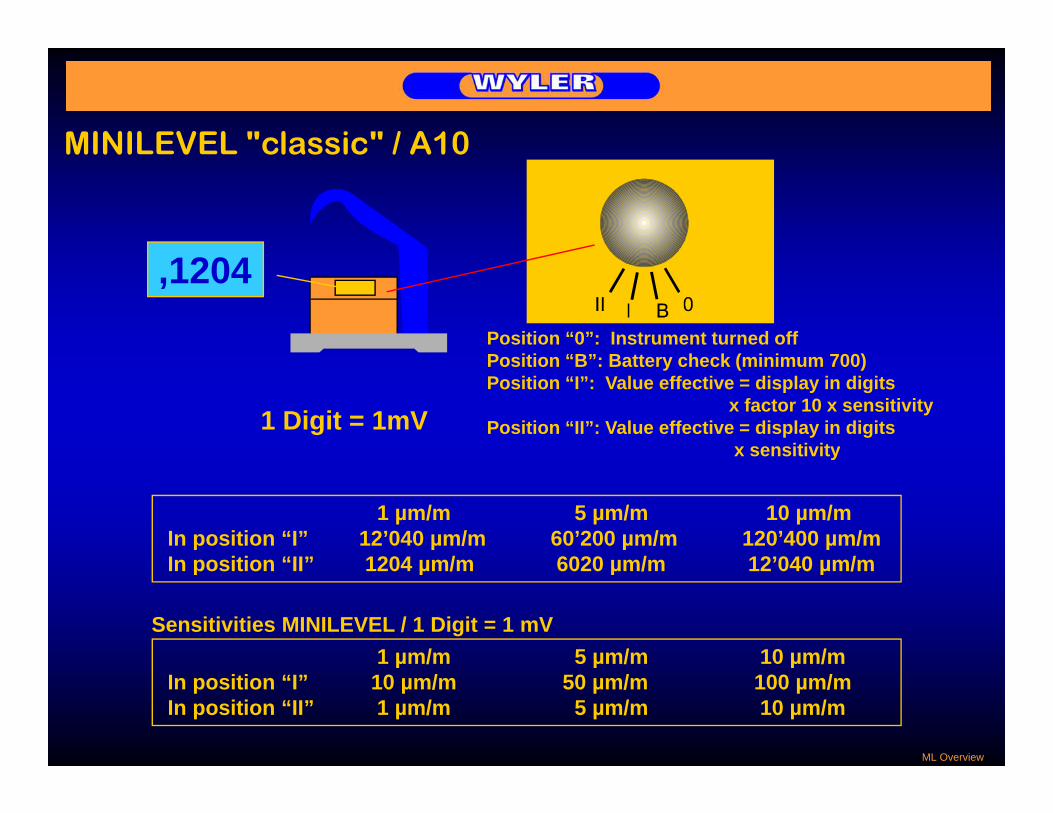
MINILEVEL "classic" / A10MINILEVEL classic / A10
Position “0”: Instrument turned offP iti “B” B tt h k ( i i 700)
,1204
Position “B”: Battery check (minimum 700)Position “I”: Value effective = display in digits
x factor 10 x sensitivityPosition “II”: Value effective = display in digits
x sensitivity1 Digit = 1mV
1 µm/m 5 µm/m 10 µm/mIn position “I” 12’040 µm/m 60’200 µm/m 120’400 µm/mIn position “II” 1204 µm/m 6020 µm/m 12’040 µm/m
y
In position “II” 1204 µm/m 6020 µm/m 12’040 µm/m
1 µm/m 5 µm/m 10 µm/mSensitivities MINILEVEL / 1 Digit = 1 mV
1 µm/m 5 µm/m 10 µm/mIn position “I” 10 µm/m 50 µm/m 100 µm/mIn position “II” 1 µm/m 5 µm/m 10 µm/m
ML Overview

MINILEVEL "classic" / A10MINILEVEL classic / A10
005 means +5 Digits,005 means +5 Digits
Position II: Measured value = + 5 digits x sensitivity
Position I: Measured value = + 5 digits x005 Position I: Measured value = + 5 digits x sensitivity x 10
,005
'125 means -125 Digitsg
Position II: Measured value = - 125 digits x sensitivity
Position I: Measured value = - 125 digits xgsensitivity x 10`125
ML Overview

LEVELTRONIC "classic" / A40LEVELTRONIC classic / A40
'1204LEVELMETER
A B OUT
1 µm/m 5 µm/m 10 µm/mDisplay - 1204 µm/m - 6020 µm/m - 12040 µm/mDisplay 1204 µm/m 6020 µm/m 12040 µm/m
1 µm/m 5 µm/m 10 µm/mSensitivities MINILEVEL / 1 digit = 1 mV
1 µm/m 5 µm/m 10 µm/mDisplay 1 µm/m 5 µm/m 10 µm/m
LT Overview

LEVELTRONIC "classic" with Levelmeter 25,LEVELTRONIC classic with Levelmeter 25,Differential measurement
LevelmeterMeasuring direction Levelmeter
LEVELMETER
Measuring instrument
'1204
A B OUTMeasuring instrument
Redcable
Grey cable
Reference instrument
Grey cable
LT Overview

MINILEVEL “NT" / A11MINILEVEL NT / A111 µm/m: 5 µm/m 10 µm/m
Range 1: +/- 20 mm/m +/- 100 mm/m +/- 200 mm/mRange 2: +/- 2 mm/m +/- 10 mm/m +/- 20 mm/m
Output: 1mV / 1µm/m 1mV / 5µm/m 1mV / 10µm/m
or Angle in µm/m or Arcsec (Format RS485)
M
Messen / Measuring
Aus/OffWYLER AG SWITZERLAND
M+
Einstellung MessbereichChanging Range
Justierung NullpunktAdjustment ZeroRange II mm/m
MINILEVEL NT
M- + / -
+ / -
ML NT Display
Changing RangeMINILEVEL NT / > 5 sec> 60 min

Display / OutputDisplay / Output
MINILEVEL „classic“
Output: +/- 2000 mV
MINILEVEL NT“1 digit =LM C25
LEVELMETER
Display : Display :
MINILEVEL „NTg1 mV Output:
+/- 2000 mV
'1204
A B OUT
Range II: +/- 2000 digitsRange I: +/- 2000 digitsRange II: +/- 2000 digitsRange I: +/- 2000 digits and / or
Display: Range II: Angle in µm/m or ArcsecR I A l i / A
Display: Range II: Angle in µm/m or ArcsecR I A l i / A
Angle in format RS485
Display/Output
Range I: Angle in µm/m or ArcsecRange I: Angle in µm/m or Arcsec LM2000

MINILEVEL “NT" / A11MINILEVEL “NT" / A11MINILEVEL NT / A11MINILEVEL NT / A11
WYLERSEAL-TEC R
LCD-Print
Processor-+/-2V DC
orPrint RS485
ML NT Display
Sensor with pendulum / N2 (nitrogene)

MINILEVEL NT and LEVELTRONIC NTMINILEVEL NT and LEVELTRONIC NT
The new productline MINILEVEL NT / LEVELTRONIC NT is well suited fori i t f ll lprecision measurements of small angles.
- Large LCD digital display, two sensitivities can be selected(MINILEVEL NT only)
- Precise zero point adjustment by using the push buttons
MINILEVEL NT
j y g- Rugged precision aluminium housing for protecting against
external influences - State of the art digital technology combined with the use of
modern electronic components allows signal output i di it l d l fin digital and analogue form
- Possibility of connection to a Levelmeter C25 or Levelmeter 2000, as well as to the Leveladapterset 2000combined with the flatness measurement software “WYLER LEVELSOFT”WYLER LEVELSOFT
- Power supply with common 1,5 V-Batteries- Fulfils the CE requirements (immunity against
electromagnetic smog) - All standard measuring bases are available
LEVELTRONIC NT
g- Available with calibration in Arcsec or µm/m
ML vs LT

Choice of the ideal instrumentChoice of the ideal instrument- Installation and adjustment of machines- Measurement of surface flatness- No interference by magnetic
- Installation and adjustment of machines- Measurement of surface flatness- No interference by magnetic
MINILEVEL " l i "
fields (Electric motors etc.)- Highly shock resistant- Integrated display- 2 ranges of measurement, useful
fields (Electric motors etc.)- Highly shock resistant- Integrated display- 2 ranges of measurement, useful
MINILEVEL "classic" for coarse adjustmentfor coarse adjustment MINILEVEL "NT"
- Installation and adjustment of machines- No interference by magnetic
fields (Electric motors etc.)- Highly shock resistant
- Installation and adjustment of machines- No interference by magnetic
fields (Electric motors etc.)- Highly shock resistantg y- External display (Levelmeter)- More accurately than Minilevel when
differential mode is applied- Measurement of surface flatness
g y- External display (Levelmeter)- More accurately than Minilevel when
differential mode is applied- Measurement of surface flatness LEVELTRONIC "NT"
LEVELTRONIC "classic"
Auswahl ML-LT
LEVELTRONIC NT

WYLER PROGRAM LEVELSOFT / Introduction
Line / StraightnessLine / Straightness
Parallelswith/without twist
Parallelswith/without twist
Flatness WYLER Standardand U-Jack
Flatness WYLER Standardand U-Jack
Introduction SW LEVELSOFT
RectangularityRectangularity

Adjustment of Measuring resultsj g
The following methods of adjustments are used:
Adjustment - End points methodAdjustment - End points methodAdjustment End points method- ISO1101- Linear regression
Adjustment End points method- ISO1101- Linear regression
Example: Measurement of a line
+6Linear
0
-2
+2
+4regression9.5µm
-6
-4 End points10µmISO 1101
9µm
Adjustment ISO1101 Line

Adjustment of Measuring resultsj g
The following methods of adjustments are used:
Adjustment End points method
Example: Measurement of a line
+6
0
-2
+2
+4
-6
-4 End points10µm
Adjustment ISO1101 Line

Adjustment of Measuring resultsj g
The following methods of adjustments are used:
Adjustment ISO1101
Example: Measurement of a line
+6
0
-2
+2
+4
-6
-4ISO 1101
9µm
Adjustment ISO1101 Line

Adjustment of Measuring resultsj g
The following methods of adjustments are used:
Adj t t Li iAdjustment Linear regression
Example: Measurement of a line
+6Linear
0
2
+2
+4
Linearregression
9.5µm
-2
-6
-4
Adjustment ISO1101 Line

Measuring a lineMeasuring a line(as preparation for flatnessmeasurement)SW WYLER according to ISO1101
Moving direction '1204LEVELMETER
A B OUT
Example:Sensitivity of instrument: 1 µm/mBase length: 200 mmStep length: 180 mm
- + + ++16 +2 -4 -2 +7-4
Maximum error:
+16 +2 -42
+7
Maximum error:
13,5 µm x 180 mm1000 mm
= 2,43 µm =13,5µm0
-2
(reduced to the step length of 180 mm)-4
Linienmessung

Measuring a lineMeasuring a line(as preparation for flatness measurement)
Moving direction
- -4 Remark:When using theWYLER-Software for
0.72 µm
WYLER-Software formeasuremnt the effective value will be read in
- 4 µm/m
180 mm
Linienmessung II
1000 mm

Measurement of two guide waysg yExercise
Prosedure:1. Measuring the reference line2 Measuring the parallel guide way2. Measuring the parallel guide way3. Measuring the transversal lines
Remarks:The reliability of the measurement may be judged by the resulting closure error
Parallel guide way
Reference line
Vermessung von Führungsbahnen

Measurement of 90° angles ongmeasuring bases and workpieces
1 2
αα
+ - + -
2 1Referenz
+ -
+ -+ -
+ -2 1
B AD C
Correction = C + D2
A + B2-
α αReferenz
+ - + -
2 1
1 2
Referenz
B A
Vermessung von Messbasen und rechten Winkeln

Measurement of a 90° anglegExercise:
4µm 6µm
Vermessung eines rechten Winkels

Measurement of a 90° anglegwith Software LEVELSOFT
1. Step: Determining the angular error of the instrument using a master square with parallel sides
1. Step: Determining the angular error of the instrument using a master square with parallel sidessquare with parallel sidessquare with parallel sidesA B C D
Angular error = C + D2
A + B2
-
2. Step: Measurement of the 90 deg. angle of the object / 4 different possibilities2. Step: Measurement of the 90 deg. angle of the object / 4 different possibilities
1 21
12
2
Referenz
The Wyler LEVELSOFT is leading the way through the different software menus
Vermessung eines rechten Winkels
1
1
2
2

Measurement of a 90° anglegwith Software LEVELSOFT
3. Step: Alignment of the measuring object and determining the error 3. Step: Alignment of the measuring object and determining the error
a) Alignment of the reference line according to ENDPOINTSa) Alignment of the reference line according to ENDPOINTS
ANGLE / ENDPOINTS
Th f th d li i hTh f th d li i h
ANGLE / ENDPOINTS
0.3 µm
0 2 µm
0.4 µm
0.5 µm
The error of the second line is shown according to the various alignment methods:
- ISO 1101- ENPOINTS
The error of the second line is shown according to the various alignment methods:
- ISO 1101- ENPOINTS
0.2 µm
0.1 µm
0,0 µm
ERROR REFERENCE LINE 0.6 µm ENPOINTS- LINEAR REGRESSION
ENPOINTS- LINEAR REGRESSION
µ
ERROR 2ND LINE BASED ON ISO1101 0.6 µm
END POINTS 0.2 µm
LINEAR REGRESSION 0.1 µm
Vermessung eines rechten Winkels
CORRECTION OF INSTRUMENT -2,58 µm/m

Measurement of a 90° anglegwith Software LEVELSOFT
3. Step: Alignment of the measuring object and determining the error 3. Step: Alignment of the measuring object and determining the error
b) Alignment of the reference line according to ISO 1101b) Alignment of the reference line according to ISO 1101
ANGLE / ISO1101
Th f th d li i hTh f th d li i h
ANGLE / ISO1101
0.3 µm
0 2 µm
0.4 µm
0.5 µm
The error of the second line is shown according to the various alignment methods:
- ISO 1101- ENPOINTS
The error of the second line is shown according to the various alignment methods:
- ISO 1101- ENPOINTSERROR REFERENCE LINE 0.5 µm
0.2 µm
0.1 µm
0,0 µm
ENPOINTS- LINEAR REGRESSION
ENPOINTS- LINEAR REGRESSION
µ
ERROR 2ND LINE BASED ON ISO1101 0.7 µm
END POINTS 0.1 µm
LINEAR REGRESSION 0.2 µm
Vermessung eines rechten Winkels
CORRECTION OF INSTRUMENT -2,58 µm/m

Measurement of a 90° anglegwith Software LEVELSOFT
3. Step: Alignment of the measuring object and determining the error 3. Step: Alignment of the measuring object and determining the error
c) Alignment of the reference line according to LINEAR REGRESSIONc) Alignment of the reference line according to LINEAR REGRESSION
ANGLE / LINEAR REGRESSION
Th f th d li i hTh f th d li i h
ANGLE / LINEAR REGRESSION
0.3 µm
0 2 µm
0.4 µm
0.5 µm
The error of the second line is shown according to the various alignment methods:
- ISO 1101- ENPOINTS
The error of the second line is shown according to the various alignment methods:
- ISO 1101- ENPOINTSERROR REFERENCE LINE 0.5 µm
0.2 µm
0.1 µm
0,0 µm
ENPOINTS- LINEAR REGRESSION
ENPOINTS- LINEAR REGRESSION
µ
ERROR 2ND LINE BASED ON ISO1101 0.6 µm
END POINTS 0.0 µm
LINEAR REGRESSION 0.1 µm
Vermessung eines rechten Winkels
CORRECTION OF INSTRUMENT -2,58 µm/m
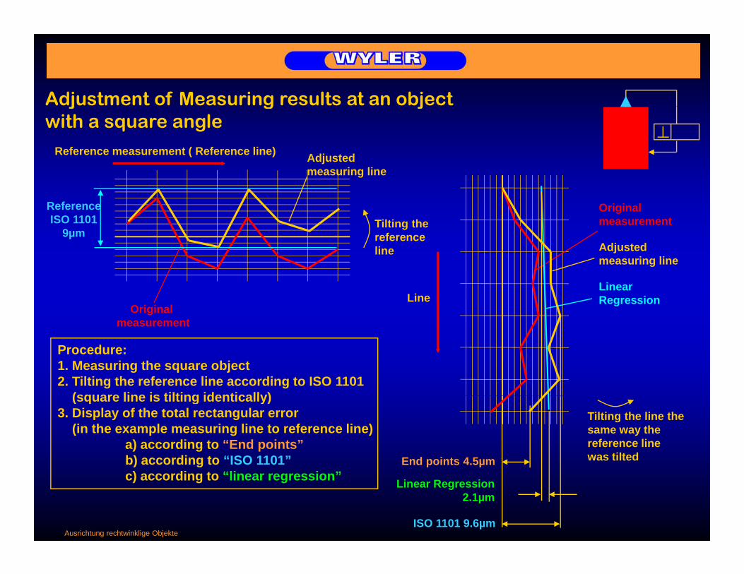
Adjustment of Measuring results at an object j g jwith a square angle
Adjusted measuring line
Reference measurement ( Reference line)
Original measurement
ReferenceISO 1101
9µmTilting the referenceline Adjusted
Original measurement
line
Linear Regression
djustedmeasuring line
Line
measurement
Procedure:1. Measuring the square object2. Tilting the reference line according to ISO 1101
(square line is tilting identically)Tilting the line the same way the reference line was tilted
(square line is tilting identically)3. Display of the total rectangular error
(in the example measuring line to reference line)a) according to “End points”b) according to “ISO 1101” End points 4.5µm
Ausrichtung rechtwinklige Objekte
c) according to “linear regression”
ISO 1101 9.6µm
Linear Regression2.1µm

Flatness Measurement with WYLER InclinometersFlatness Measurement with WYLER InclinometersFlatness Measurement with WYLER Inclinometersand WYLER SoftwareFlatness Measurement with WYLER Inclinometersand WYLER Software
SURFACE GRID WYLER
Length: 1200 mm Witdh: 800 mm
Maximum error: 4,0 μm Closure error: 0,3 μm
Graphic display of profile
As an option the connection to a PC is available:Options:
- Leveladapter - Measurement-Software
Operating Systems:Engineer Set consists of:
- 2 Minilevel "NT"
Ebenheitsmessungen mit WYLER Messgeräten und Mess-Software
Operating Systems:DOS / Win 3.11 / WIN 95 / Win NT 3.5 or higher - Levelmeter 2000
- Cable with „dongle“

Flatness measurement with LEVELTRONIC "classic"Moving direction
Personal Computer
Measuring instrument
'1204LEVELMETER
Leveladapter 2000
A B OUT
Reference instrument
ATTENTION: - Connect the red cable to the measuring instrument- Always measure in the direction of the cable
Flächenmessung mit LEVELTRONIC "classic"

Flatness measurement with MINILEVEL "classic"Moving direction
Personal Computer
Measuring instrument
Leveladapter 2000
Reference instrument
ATTENTION: - Remove batteries (MINILEVEL "classic" only)- Check the correct sensitivity- Connect the red cable to the measuring instrument
Al i th di ti f th bl- Always measure in the direction of the cable
Flächenmessung mit MINILEVEL "classic"
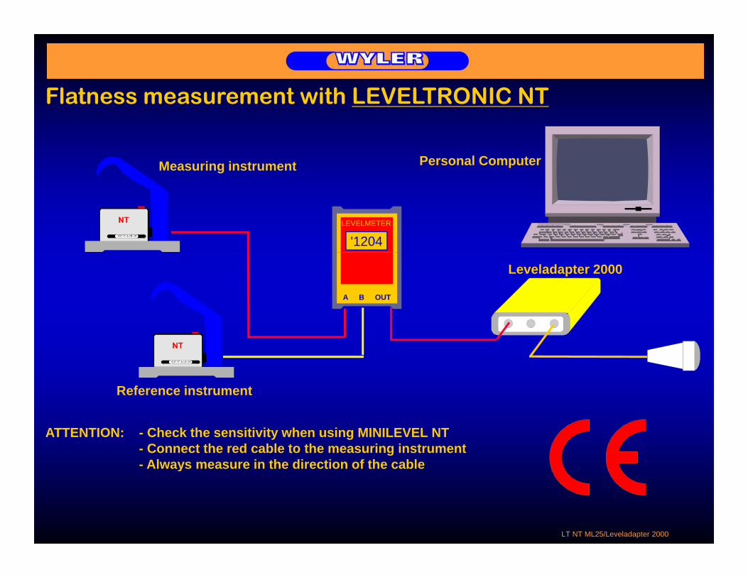
Flatness measurement with LEVELTRONIC NT
Measuring instrument Personal Computer
'1204LEVELMETER
Leveladapter 2000
A B OUT
Reference instrument
ATTENTION: - Check the sensitivity when using MINILEVEL NT- Connect the red cable to the measuring instrument- Always measure in the direction of the cabley
LT NT ML25/Leveladapter 2000

Flatness measurement with MINILEVEL NT
Personal Computer
Measuring instrument
Leveladapter 2000
Reference instrument
ATTENTION: - Check the sensitivity when using MINILEVEL NT- Connect the red cable to the measuring instrument- Always measure in the direction of the cabley
LT NT Leveladapter 2000

Flatness measurement with MINILEVEL NT orLEVELTRONIC NT with Levelmeter 2000
Measuringinstrument
Levelmeter 2000
R f i t t
Using a Levelmeter 2000 instead of a Levelmeter C25dditi l f t il bl lik
Reference instrument
additional features are available like:"ZERO"-Setting, various measuring units, and so on
LT NT Levelmeter 2000

NEW !!!„Remote Display“ for MINILEVEL and LEVELTRONIC „NT“
LT NT with remote display

Preparation for Flatness Measurement
1. Cleaning of the surface plate (on the previous day)2. Place the instruments on the surface plate for acclimatization3. Connecting the instruments (and Levelmeter) to the computer;
remove batteries (Levelmeter Minilevel “classic” only)
1. Cleaning of the surface plate (on the previous day)2. Place the instruments on the surface plate for acclimatization3. Connecting the instruments (and Levelmeter) to the computer;
remove batteries (Levelmeter Minilevel “classic” only)remove batteries (Levelmeter, Minilevel “classic” only)4. Turn on the Leveladapter 20005. Turn on the computer (after connecting the
instruments)6. Adjust surface plate to within +/- 50 µm/m with
remove batteries (Levelmeter, Minilevel “classic” only)4. Turn on the Leveladapter 20005. Turn on the computer (after connecting the
instruments)6. Adjust surface plate to within +/- 50 µm/m with j p µ
Spirit Level or Leveltronic/Minilevel.Attention: Loosen the safety supports first !
7. Prepare the software programme for the measurement with the necessary dataAttention: When measuring with 2 Leveltronics
j p µSpirit Level or Leveltronic/Minilevel.Attention: Loosen the safety supports first !
7. Prepare the software programme for the measurement with the necessary dataAttention: When measuring with 2 LeveltronicsAttention: When measuring with 2 Leveltronics
and Levelmeter, INPUT: "Measurement with one
instrument" Adjust correct sensitivity
Attention: When measuring with 2 Leveltronics and Levelmeter,
INPUT: "Measurement with oneinstrument"
Adjust correct sensitivity8. Calculation of the best fit grid and draw it on the
surface plate, after that cleaning of the plate again. Free space at edge minimum 1/2 base width.
9. Execute test measurement, line with approx. 20 steps without moving the instrument
8. Calculation of the best fit grid and draw it on the surface plate, after that cleaning of the plate again. Free space at edge minimum 1/2 base width.
9. Execute test measurement, line with approx. 20 steps without moving the instrumentapprox. 20 steps without moving the instrument
10. Start with flatness measurement, check correct switch position of MINILEVEL
11. After the measurement apply MICROPOLISH for conditioning the plate
approx. 20 steps without moving the instrument10. Start with flatness measurement, check correct
switch position of MINILEVEL11. After the measurement apply MICROPOLISH for conditioning the plate
Vorbereitungen Ebenheit

Basics on surface flatness measurement
Influence of temperature:A temperature difference of 1 degree Celsius between the upper and the lower side of a plate of 1m length results already in a deformation of the plate of 6 to 7 µm1m length results already in a deformation of the plate of 6 to 7 µm
Surface flatness according to DIN 876 / ISO1101:Flatness of granite surface plates (DIN 876 / ISO1101)Quality Maximum error in µm
SURFACE GRID WYLER
Length: 1200 mm Witdh: 800 mm
00 2 x ( 1 + Länge in [m] )0 4 x ( 1 + Länge in [m] )1 10 x ( 1 + Länge in [m] )2 20 x ( 1 + Länge in [m] )
Choice of measuring base:Ideal measuring base: Flat steel base with dust groves
Measuring step length:Maximum error: 4,0 μm Closure error: 0,3 μm
Length of the base Optimal step length Recommended step length110 mm 90 mm 85 ... 105 mm150 mm 126 mm 120 ... 145 mm200 mm 170 mm 160 ... 190 mm
Schrittlänge

Basics on surface flatness measurement
SURFACE GRID WYLER
Length: 1200 mm Witdh: 800 mm
Prerequisite:• Max. temp. difference top/bottom = 2°C• After cleaning: 2 hours drying time gAfter cleaning: 2 hours drying time
Grade t1 in µm
000
2 (1 + Länge in m)4 (1 + Lä i )
Maximum error: 4,0 μm Closure error: 0,3 μm
012
4 (1 + Länge in m)10 (1 + Länge in m)20 (1 + Länge in m)
Flatness error of a partial areaSize of area Max. tolerance t2 in µm
250 x 250 mm00 0 1 2
3µm 5µm 13µm 25µm250 x 250 mm 3µm 5µm 13µm 25µm
Accepted border zone:2% of width of plate, max. 20mm
Schrittlänge
2% of width of plate, max. 20mm

Preparation of a granite p gsurface plate for flatness measuring
22% of length 22% of length
Supporting points according to “Bessel”
% o
f wid
th
Size of granite plate: 1200 x 800 mmMeasuring system used::1 LEVELTRONIC 1 µm/m, Base length 200 mm1 LEVELTRONIC 1 µm/m, Base length 150 mm
22%
mm
Preparation:1. Preparation according to special
instructions, like e.g. set to level. cleaning, etc.
4 x
190m
cleaning, etc. 2. Defining the edge zone (about ½ of the
width of base, max. 20 to 30 mm)3. Definition of the measuring step length4. Drawing the grid on the plate
edge 30 mm
30 m
m6 x 190mm
For the example :Baselength: 200mm (recommended step length: 160 ... 190 mm)
edge
3
Vorbereitungen einer Mess- und Kontrollplattefür die Ebenheitsmessung
Step length:longitudinal 6 x 190 mm + 2 x 30 mm edgetransversal 4 x 190 mm + 2 x 20 mm edge

Remarks: Determining the maximum error is always according to ISO 1101Remarks: Determining the maximum error is always according to ISO 1101Remarks: Determining the maximum error is always according to ISO 1101Remarks: Determining the maximum error is always according to ISO 1101
Flatness according to ISO1101 withoutcorrection of the closure errorFlatness according to ISO1101 withoutcorrection of the closure error
SURFACE GRID WYLER
L th 1200 Witdh 800 correction of the closure error
The closure error should not exceed 20% to 25% of the max. error
correction of the closure error
The closure error should not exceed 20% to 25% of the max. error
Length: 1200 mm Witdh: 800 mm
Maximum error: 4,0 μm Closure error: 0,3 μm SURFACE GRID WYLER
Length: 1200 mm Witdh: 800 mm
Flatness according to ISO1101 withFlatness according to ISO1101 with
Vermessung von Messbasen und rechten WinkelnVermessung von Messbasen und rechten Winkeln
gcorrection of the closure error
gcorrection of the closure error
Maximum error: 4,0 μm Closure error: 0,3 μm

Geometrical inspection ofGeometrical inspection ofmachine tools
“ROLL” error
“PITCH” error
Roll / Pitch

Geometrical inspection of
I ti f
Geometrical inspection ofmachine tools
RInspection ofmachine tool table
R
R
M
R
M
Geometrical inspection ofan instable structure
RM
Vermessung Maschinen

LEVELMATICLEVELMATICPrecision transducer
Various transducers in different configurations available
e.g. precision transducers are availablealso in two axis configuration with LED bar display
Levelmatic 30 Levelmatic 31 Levelmatic 34
Measuring range +/- 2 mRad ... +/- 2 mRad... +/- 5 ... +/- 45 degrees +/- 30 degrees +/- 60 degrees
Linearity 0.5% FS 0.5% FS 0.5% FSOutput signal Levelmeter B25 +/- 2 V DC und +/- 2 V DC
Levelmeter C25
Levelmatic

Inclination measuring instruments based on
Inclination measuring instruments based onbased on
digital techniquebased on
digital technique
Part 3Part 3Part 3Part 3
Digitaltechnik Titel

ZEROTRONICZEROTRONIC
Objectives for the development of Objectives for the development of the new sensorthe new sensor
•High resolution, high accuracy•Low temperature dependency•Digital technique; use of microprocessors
•High resolution, high accuracy•Low temperature dependency•Digital technique; use of microprocessorsDigital technique; use of microprocessors•Measuring range from +/- 1 up to +/- 60 degrees•Measurement under dynamic conditionsDisplay for graphical analysis and on line monitoring
Digital technique; use of microprocessors•Measuring range from +/- 1 up to +/- 60 degrees•Measurement under dynamic conditionsDisplay for graphical analysis and on line monitoring•Display for graphical analysis and on-line monitoring
•Galvanic disconnection for outdoor applications•Display for graphical analysis and on-line monitoring•Galvanic disconnection for outdoor applications
Ziele ZERO

ZEROTRONIC / Housing gastightZEROTRONIC / Housing gastightDesign of ZEROTRONIC:- Sensor including pendulum held by Archimedes helical springs
Design of ZEROTRONIC:- Sensor including pendulum held by Archimedes helical springs
- RC - Oscillator- Voltage stabilisator with level-shifter- Digital frequency counter with calibration data
memory and asynchronous serial port
- RC - Oscillator- Voltage stabilisator with level-shifter- Digital frequency counter with calibration data
memory and asynchronous serial port- Voltage stabilisator- Housing and mounting bracket- Housing and mounting bracket - Voltage stabilisator- Digital frequency counter- Calibration data memory- Asynchronous serial port
Pendelum
Connectorfor RS 485
Aufbau ZERO
Housinggastight
RC-OscillatorElektrodes
Mounting bracket

ZEROTRONIC / Housing gastight
Design of ZEROTRONIC:- Sensor including pendulum held byArchimedes helical springs
Design of ZEROTRONIC:- Sensor including pendulum held byArchimedes helical springs
ZEROTRONIC / Housing gastight
Archimedes helical springs- RC - Oscillator- Voltage stabilisator with level-shifter- Digital frequency counter with
calibration data
Archimedes helical springs- RC - Oscillator- Voltage stabilisator with level-shifter- Digital frequency counter with
calibration data - Voltage stabilisatorcalibration datamemory and asynchronous serial port
- Housing and mounting bracket
calibration datamemory and asynchronous serial port
- Housing and mounting bracket
Pendelum- Digital frequency counter- Calibration data memory- Asynchronous serial port
Connectorfor RS 485
WYLERWYLERSEAL-TEC R
Housinggastight
RC-OscillatorElektrodes
Mounting bracketQuerschnitt ZERO mit 3 Prints gastight

ZEROTRONIC / OUTPUTZEROTRONIC / OUTPUT
TYPE 2OUT IN
F and F [Hz] Measuring rateTYPE 2 F1 and F2 [Hz] Measuring rateCalibration data
Temp [Hz]RS485
OUT IN
F1 and F2 [Hz] Measuring rateCalibration dataRS485
TYPE 3
Temp [Hz]
Angle in [Rad] Measuring rate(Angle calculatedRS485
in sensor)
0.5 ... 2.5 ... 4.5 [V] / 5.0 [V] VDDAnalogueOutput
ZERO gastight OUTPUT digital analog
4 ... 12 ... 20 [mA] / 12 ... 24 [V] VDDOutput

ZEROTRONICZEROTRONICComparison between ZEROTRONIC type 2 and type 3Comparison between ZEROTRONIC type 2 and type 3
ZEROTRONIC TYPE 2ZEROTRONIC TYPE 2 ZEROTRONIC TYPE 3ZEROTRONIC TYPE 3
Power consumptionPower consumption 50% 100%100%Power consumptionPower consumption
Interface electronicInterface electronic
Interface data formatInterface data format
50%
IdenticalIdentical
100%100%
IdenticalIdentical
IdenticalIdentical IdenticalIdentical
Data volume transmittedData volume transmitted
LARGELARGEWhen starting a measurement theWhen starting a measurement thecalibration data must be transmitted.calibration data must be transmitted.With every measurement theWith every measurement thefrequencies F1 & F2 as well as thefrequencies F1 & F2 as well as thecalibration data must be transmittedcalibration data must be transmitted
SMALLSMALLOnly the angle in RAD is Only the angle in RAD is transmitted from sensor to hosttransmitted from sensor to host
Host computerHost computerperformanceperformance
calibration data must be transmittedcalibration data must be transmitted
HIGHHIGHComputing the angle from frequencies Computing the angle from frequencies and calibration data receivedand calibration data received
LOWLOWAngle is computed in the sensorAngle is computed in the sensor
Internal measuring rateInternal measuring rate
VariousVarious
Depending on the host‘s sampling Depending on the host‘s sampling rate set:rate set:measurements of objects with lowmeasurements of objects with lowfrequency vibration is difficultfrequency vibration is difficult
The sampling rate in the sensor isThe sampling rate in the sensor is100/ sec.; this allows high quality100/ sec.; this allows high qualitymeasurements on objects with lowmeasurements on objects with lowfrequency vibrations.frequency vibrations.
- VI for LabVIEW (National Instr)- VI for LabVIEW (National Instr)
ZERO gastight OUTPUT digital analog
VariousVarious VI for LabVIEW (National Instr)VI for LabVIEW (National Instr)- Easy programming for customer- Easy programming for customer

Digital measuring pricipleg g p p(ZEROTRONIC / CLINO / CLINO 2000)
Voltage-stabilisator
Digital frequency counter
asynchronous serial port
PendelumSelector
Oscillator(EXT)
GND
+5V
RTA
RTB
PWM
RTS
ConnectorC1 C2
R
ConnectorC1 C2
RTS
(AUX)
R const
Frequency = f (C)
SIGNAL
1
2Position “Selector”
C var
Position “Selector”
Frequency
Messproinzip ZERO
Inverter

Digital measuring principleDigital measuring principleprinciple function of a RC-Oscillator / part 1
UAR UA
R
C var UCC var UC
UC
UA
UC
UAUA UA
Charge Discharge
Laden/Entladen Kondensator
t t

Digital measuring principleDigital measuring principleprinciple function of a RC-Oscillator / part 2
Schmitt-
U in U out
Simplified description of“principle function of a Schmittrigger”
Schmitt-trigger
U+U+
U-
t
U-
U+ positive thresholdU - negative threshold
Schmitt-Trigger

Digital measuring principle R constDigital measuring principleRC Oscillator
1 2 Inverter
C left C rigth
Funktion ZERO

Calibration of a digital measuring system
1. Calibration of the system Number of calibration points:
Clinotronic: 21
Calibration of a digital measuring systemF1/F2 (F1,F2)
2 Th lib ti i t
Clinotronic: 21Zerotronic: free to chose
2. The calibration points will be stored
Angle
F1/F2 (F1,F2)
Angle
Kalibrierung I

Calibration of a digital measuring systemCalibration of a digital measuring system
3. Calculation of the individualvalues between the calibrationpoints by means of interpolation
F1/F2 (F1,F2)
Calibration
p y p
Angle
point
T=40°CT=20°CT 0°C
F1/F2 (F1,F2)
T= 0°C
F1 30°F2 30°
Angle
4. Calibration at differenttemperatures
Angle
Setting of calibration devicee.g. -30 degrees
Kalibrierung II

Calibration of a digital measuring systemCalibration of a digital measuring system
T=40°C
F1/F2 (F1,F2)
T 40 CT=20°CT= 0°C
Angle-50° -40° -30° -20° -10° 10° 40°30°20° 50°
Calibration
Measurement
Kalibrierung II

Calibration of a digital measuring systemCalibration of a digital measuring systemTypical curves of the frequencies of +CLINO PLUS+
Frequency F1 Frequency F2Frequency in [Hz]
500‘000
Frequency F1 Frequency F2
480‘000
460‘000
440‘000
50° 20°40° 30° 10° 10° 40°30°20° 50°
420‘000
400‘000
Kalibrierung II
-50° -20°-40° -30° -10°0°
10° 40°30°20° 50°

Elimination of ZERO-OffsetElimination of ZERO OffsetAngle eff
45°45°
Angle nominalZERO-Offset
z.B. 45°
The ZERO-Offset canbe eliminated with areversal measurement
ZERO OffsetZERO Offset

Elimination of ZERO- and GAIN-OffsetElimination of ZERO and GAIN Offset1. ZERO- and Gain-Offset1. ZERO- and Gain-Offset
Angle eff.
G i Off t
2. Eliminating the ZERO-OffsetAngle eff.
Gain-Offset
Angle
45°
ZERO Offset
Gain-Offset
The ZERO-Offset canbe eliminated with areversal measurement(Zerotronic, Clino45
Angle
45°
Angle nominal e.g. 45°
ZERO-Offset and Clino2000) Angle nominal e.g. 45°
3. Eliminating Gain-Offset3. Eliminating Gain-OffsetggAngle eff.
45°
Th GAIN Off t
Angle nominal z.B. 45°
The GAIN-Offset canbe eliminated with a„stick calibration“(Clino2000 and ZEROTRONIC only)
Zero-/Gain-Offset
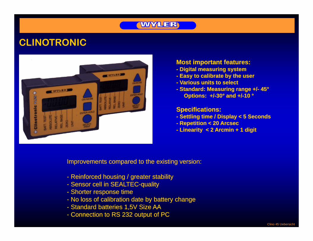
CLINOTRONICCLINOTRONIC
Most important features:- Digital measuring system
Easy to calibrate by the user
Most important features:- Digital measuring system
Easy to calibrate by the user- Easy to calibrate by the user- Various units to select- Standard: Measuring range +/- 45°
Options: +/-30° and +/-10 °
- Easy to calibrate by the user- Various units to select- Standard: Measuring range +/- 45°
Options: +/-30° and +/-10 °
Specifications:- Settling time / Display < 5 Seconds- Repetition < 20 Arcsec- Linearity < 2 Arcmin + 1 digit
Specifications:- Settling time / Display < 5 Seconds- Repetition < 20 Arcsec- Linearity < 2 Arcmin + 1 digit
Improvements compared to the existing version:Improvements compared to the existing version:
- Reinforced housing / greater stability- Sensor cell in SEALTEC-quality- Shorter response time
- Reinforced housing / greater stability- Sensor cell in SEALTEC-quality- Shorter response time
Clino 45 Uebersicht
- No loss of calibration date by battery change- Standard batteries 1,5V Size AA- Connection to RS 232 output of PC
- No loss of calibration date by battery change- Standard batteries 1,5V Size AA- Connection to RS 232 output of PC

CLINOTRONICCLINOTRONIC
Exercise:1. Change and store unit
of measurement2 Eliminating the zero offset
Exercise:1. Change and store unit
of measurement2 Eliminating the zero offset2. Eliminating the zero-offset
by means of a reversal measurement
3 HOLD function
2. Eliminating the zero-offset by means of a reversal measurement
3 HOLD function3. HOLD function4. Calibration
a) Calibration manuallyb) Calibration automatically
3. HOLD function4. Calibration
a) Calibration manuallyb) Calibration automaticallyb) Ca b at o auto at ca yb) Ca b at o auto at ca y
Clino Uebung

CLINO 2000 The new digital inclination measuringThe new digital inclination measuringCLINO 2000 The new digital inclination measuringinstrument for a great variety ofmeasuring tasks, fulfils all requirements
The new digital inclination measuringinstrument for a great variety ofmeasuring tasks, fulfils all requirements
Most important features:Most important features:Most important features:- Highest possible precision over the large measuring range of +/- 45° with integrated temperature compensation
- Effortless zero adjustment by using the integrated software and a reversal measurement
Most important features:- Highest possible precision over the large measuring range of +/- 45° with integrated temperature compensation
- Effortless zero adjustment by using the integrated software and a reversal measurement
- Most modern digital electronic components- Fulfils the strict CE requirements (immunity against electromagnetic smog)
- Easy to calibrate due to the implemented software guidance and the calibration aids
- Most modern digital electronic components- Fulfils the strict CE requirements (immunity against electromagnetic smog)
- Easy to calibrate due to the implemented software guidance and the calibration aidsand the calibration aids
- Most common units available- Standard: Measuring range +/- 45°Options: +/- 60°, +/- 30° und +/- 10 °
S ifi ti
and the calibration aids- Most common units available- Standard: Measuring range +/- 45°Options: +/- 60°, +/- 30° und +/- 10 °
S ifi tiSpecifications:- Settling time < 5 seconds- Resolution 5 Arcsec- Limits of error: < 5 Arcsec + 0.07% R.O.- Data connection: RS485, asynchr., 7 Bit, 2 Stopbits,
Specifications:- Settling time < 5 seconds- Resolution 5 Arcsec- Limits of error: < 5 Arcsec + 0.07% R.O.- Data connection: RS485, asynchr., 7 Bit, 2 Stopbits, , y , , p ,
no parity, 9600 Baud, y , , p ,
no parity, 9600 Baud
Clino 2000

ZEROTRONIC / „ANALOGUE“ OUTPUTZEROTRONIC / „ANALOGUE OUTPUT
Angle = 0Vcc=5V
OutputØ 2.5VAngle 0
Angle = +FS
0VØ 2.5V
Ø 4.5V
Analogue Output
Angle = -FS Ø 0.5V
100%=277.7µS
10%=27.77µSF=3.6kHz
Analogue Output(PWM)
10% 27.77µS
P l 12 24V+5V
GND
PWM
Power supply 12 ... 24V
4 ... 20mA
GNDR UR
Inte
rfac
e
ZERO gastight OUTPUT analog
GND GNDI
„Current loop“

ZEROTRONICZEROTRONIC
Angle 0 degrees
Angle positive;e.g. +10 degreesSensor-Type
xA - xxx 1° - SensorxB - xxx 5° - SensorxC - xxx 10° - Sensor
Angle negative;e.g. -10 degrees
xD - xxx 30° - SensorxE - xxx 60° - Sensor
Zero, Nummern

ZEROTRONICZEROTRONICExternal
power supply Transceiver/Converter
Transceiver/Converter
T
CRS232 C
RS485
ZEROTRONIC-Sensorswith T/C (Transceiver/Converter)connected to a Personal Computer
RS485
Zero mit T/C

ZEROTRONICZEROTRONICTransceiver/Converter
Transceiver/Converter
T
C
Levelmeter 2000
C
RS485
ZEROTRONIC-Sensorswith T/C (Transceiver/Converter)
RS485
connected to a Levelmeter 2000
Zero/TC/LM2000

ZEROTRONICZEROTRONICFrequencies f1 und f2Calibration dataMeasuring rate
RS 485
Angle andmeasuring unit
RS 485
RS 232
DDE /Dynamic RS 485
RS 232 Data Exchange)
F t f d t t f
RS 232
Format of data transfer
Header (4) Trailer (1)Check-sum (2)Address (3) Opcode (1) Data (8)
Transmission data format: asynchron / 7 Bit / 2 Stopbits / no parity
Bit-System
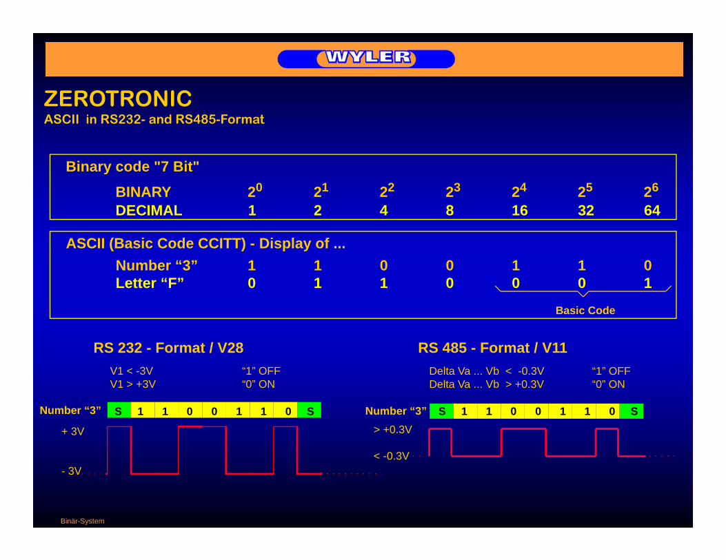
ZEROTRONICZEROTRONICASCII in RS232- and RS485-Format
Binary code "7 Bit"y
BINARY 20 21 22 23 24 25 26
DECIMAL 1 2 4 8 16 32 64
ASCII (Basic Code CCITT) - Display ofASCII (Basic Code CCITT) - Display of ...Number “3” 1 1 0 0 1 1 0Letter “F” 0 1 1 0 0 0 1
Basic Code
RS 232 - Format / V28V1 < -3V “1” OFFV1 > +3V “0” ON
RS 485 - Format / V11Delta Va ... Vb < -0.3V “1” OFFDelta Va Vb > +0 3V “0” ONV1 > +3V 0 ON
Number “3”
+ 3V
S 1 1 0 0 1 1 0 S S 1 1 0 0 1 1 0 SNumber “3”> +0.3V
< -0 3V
Delta Va ... Vb > +0.3V 0 ON
- 3V< -0.3V
Binär-System
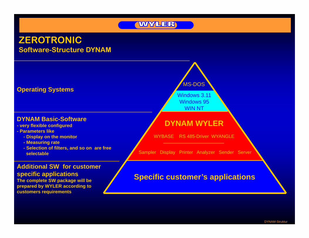
ZEROTRONICSoftware-Structure DYNAM
Operating SystemsMS-DOS
Windows 3.11Windows 95
DYNAM Basic-Software- very flexible configured- Parameters like
WIN NT
DYNAM WYLER- Display on the monitor- Measuring rate- Selection of filters, and so on are free
selectable
S f
WYBASE RS 485-Driver WYANGLE
Sampler Display Printer Analyzer Sender Server
Additional SW for customer specific applicationsThe complete SW package will be prepared by WYLER according tocustomers requirements
Specific customer’s applications
q
DYNAM-Struktur

ZEROTRONIC Display on the monitorSoftware-Structure DYNAM
Display on the monitorof a measurement with 2 ZEROTRONIC-Sensors and continuous monitoring of allpreviously measured values
DISPLAYwith actual values
PANELPANELthe “cockpit”
ANALYZERwhich displays allmeasured measuringvalues
Panel/Display

ZEROTRONICSoftware-Structure DYNAM
ANALYZERTool to analyse allpreviously recorded p ymeasuring values stored in different files
Analyzer

ZEROTRONIC NEW !!!Software-Structure DYNAM NEW !!!
Measurements andAnalyzations withVI‘s from WYLER
forZEROTRONIC Type 3
LabVIEW

ZEROTRONIC Transceiver / Converter
Data transmission from short distancesup to several kilometers / 1
Sensor A
Sensor B
RS 485 BUS
PCRS 485 BUS
2 Sensors without externalLevelmeter 2000
Distance up to approx. 15 meters
2 Sensors without external power supply
With additional T/C´s and externalpower supply more than 2 sensors
b t d
Levelmeter 2000
Levelmeter 2000
can be connected
Distance up to approx. 15 meters
2 Sensors with external power supply
p pp
With additional T/C´s and externalpower supply more than 2 sensorscan be connected
Distance up to approx. 15 meters2 Sensors with external power supply and 1 T/C
Up to 31 T/C´s with 2 sensors eachRS 232 Up to 31 T/C s with 2 sensors eachcan be connected
Zero Konfig I

ZEROTRONIC Transceiver / Converter
Data transmission from short distancesup to several kilometers / 2
Sensor A
Sensor B
RS 485 BUS
PCRS 485 BUS
Up to 31 T/C´s with 2 sensors eachcan be connected
Distance up to 1000 m
Up to 31 T/C´s with Distance up to 1000 m
2 sensors eachcan be connected
Distance up to
Up to 30 OPTO transceivers can be connected
Distance up toseveral 1000 m
OPTO-Transceiver
Zero Konfig II

ZEROTRONICZEROTRONICApplicationsA few typical applications for ZEROTRONIC Sensors:A few typical applications for ZEROTRONIC Sensors:
Precision inclination measurement on unstable objects likeMachine toolsAdjustment of moving platforms on boats and vessels
Precision inclination measurement on unstable objects likeMachine toolsAdjustment of moving platforms on boats and vessels
Long term monitoring with data collection and -transferBuildingsConstruction sitesB id
Long term monitoring with data collection and -transferBuildingsConstruction sitesB idBridgesDamsTunnelsInclination measurement by driving on a road
BridgesDamsTunnelsInclination measurement by driving on a road
Various applicationsAdjustment of printing machinesMeasurement of profiles (aircrafts, racing cars “formula 1”, and so on)
Various applicationsAdjustment of printing machinesMeasurement of profiles (aircrafts, racing cars “formula 1”, and so on)
Anwendungen ZERO

ZEROTRONIC
Measuring range +/- 1 degrees +/- 10 degrees +/- 30 degrees +/- 60 degrees +/- 0.5 degrees
SpecificationsZEROTRONIC ZEROMATIC 50
Resolution1 Measurement/sec
without filter +/- 0.0128 % F.S. +/- 0.00315 % F.S. +/- 0.00454 % F.S. +/- 0.00430 % F.S. +/- 0.00286 % F.S.with filter +/- 0.00429 % F.S. +/- 0.00100 % F.S. +/- 0.00124 % F.S. +/- 0.00122 % F.S. +/- 0.00100 % F.S.
10 Measurements /secwithout filter +/- 0.0358 % F.S. +/- 0.00888 % F.S. +/- 0.01430 % F.S. +/- 0.01310 % F.S. +/- 0.00859 % F.S.with filter +/ 0 0128 % F S +/ 0 00315 % F S +/ 0 00454 % F S +/ 0 00430 % F S +/ 0 00286 % F Swith filter +/- 0.0128 % F.S. +/- 0.00315 % F.S. +/- 0.00454 % F.S. +/- 0.00430 % F.S. +/- 0.00286 % F.S.
Limits of error in Arcsec Null/Gain Null/Gain Null/Gain Null/Gain Null/GainRange incl. drift 0.017 % F.S. 0.0042 % F.S. 0.0046 % F.S. 0.0037 % F.S. 0.015 % F.S.within 24h/20°C + 0.07 % R.O. + 0.02 % R.O. + 0.01 % R.O. + 0.01 % R.O. + 0.04 % R.O.
Limits of error in ArcsecRange incl. drift 0.014 % F.S. 0.055 % F.S. 0.037 % F.S. 0.028 % F.S. 0.15 % F.S.within 6 months/20°C + 0.25 % R.O. + 0.15 % R.O. + 0.1 % R.O. + 0.06 % R.O. + 0.10 % R.O.
Temperatur stabilityin Arcsec/°C
Zero point 0.04 % F.S. 0.008 % F.S. 0.005 % F.S. 0.004 % F.S. 0.04 % F.S.Gain + 0 2 % R O + 0 03 % R O + 0 02 % R O + 0 01 % R O + 0 2 % R OGain + 0.2 % R.O. + 0.03 % R.O. + 0.02 % R.O. + 0.01 % R.O. + 0.2 % R.O.
Remarks: F.S. FullscaleR.O. Readout
Spezifikationen ZERO

ZEROTRONIC
Zerotronic Sensors
Possible concept for data transfer
Office Field
Zerotronic Sensors
PC with WYLER-SW DYNAM
Modem Modem
Transceiver / Converter
Transceiver / Converter
Data report Alarm Transmission to another
station
Uebermittlung Daten

ZEROTRONICAdjustment of platforms on boats with ZEROTRONIC
Reference platform
1 Step:1. Step:“ZERO-Setting” with both sensors
Platform to be adjusted
Reference platform
2. Step:Measuring the difference between the two platforms
Platform to be adjusted
3. Step:Adjustment of the platform according to the measured deviation until the display shows “ZERO”
Schiffs-Plattformen

ZEROTRONIC ZEROTRONIC PROJECT 50Easy finding of the 90 deg DeviationZEROTRONIC PROJECT 50Easy finding of the 90 deg Deviation
1. „Zero setting“ by means of reversal
Easy finding of the 90 deg. Deviationwhen swivelling the spindle from „horizontal“ to „vertical“.Easy finding of the 90 deg. Deviationwhen swivelling the spindle from „horizontal“ to „vertical“.
1. „Zero setting by means of reversalmeasurement on horizontalposition of the spindle.
saving values (manually or PC)
2. Swivelling spindle 90 deg.
3. „Zero setting“ by means of reversalmeasurement on vertical position
Levelmeter 2000
pof the spindle.
saving values (manually or PC)
4. Calculating angular difference between the two positions of the spindle by means of pocket calculator or PC.
Maschinen ZERO

ZEROTRONICReference plate situated at the forward end of the cargo floor
ZEROTRONIC PROJECT 51Adjustment of various platforms inlarge aircrafts during assembly andmaintenance
ZEROTRONIC PROJECT 51Adjustment of various platforms inlarge aircrafts during assembly andmaintenancemaintenancemaintenance
1. Easy simultaneous „zero setting“of 4 sensors
2. Angular difference between thepairs of sensors easily visualizedon the Levelmeter
Aircraft ZERO
Differential measurement easily possible at various positions.

ZEROTRONIC Measurement of a road profilep
Task: Continous measurement of inclination by driving on a road and taking the influence of acceleration into consideration
Z t i
β1 = f (f1 and f2)β1ASIC WYLER
f1, f2 ASIC WYLER
ZerotronicSensor β = β1 - β2 DYNAM
Device for measuring
the distance
s = f (t) a = f (s, t) β2 = f (arcsin a)β
ASIC WYLEREncoder DYNAM DYNAMβ2
the distance
Calculation of the effective inclination ββ = β1 - β2β = f (arcsin a) = f {arcsin [f (s t)]}β2 = f (arcsin a) = f {arcsin [f (s, t)]}
a: Acceleration [m/s2] (=dv/dt = v’ = s’’)s: Distance [m] f1, f2: Frequencies Sensors
EMPA

ZEROTRONIC Measurement of a road profilep
EMPA Analyzer