Www.fairchildsemi.com FSC LCD Display Solution Lighting Product Line Power Conversion.
Upload
patrick-jenningsCategory
view
227download
5
www.fairchildsemi.com
Fairchild Power Switch(FPS)
TV Solution
Power Conversion

2
Features and Advantages of FSCQ-series
Features• Optimized for Quasi-resonant converter (Low EMI and High Efficiency)• Fully avalanche rated and 100% tested SenseFET• Pulse-by-pulse current limiting• Improved reliability through various protection functions
Over voltage, Over load, Over current, Thermal shutdown
• Advanced Burst operation for low power consumption in standby (<1W)• Internal Soft start function (20ms)• Extended Quasi-resonant operation for wide operation range• Reduced startup and operating currents
Advantages• Reduced board space (simple & compact circuit design)• Decreased assembly time and field failure rate Enhanced productivity
3
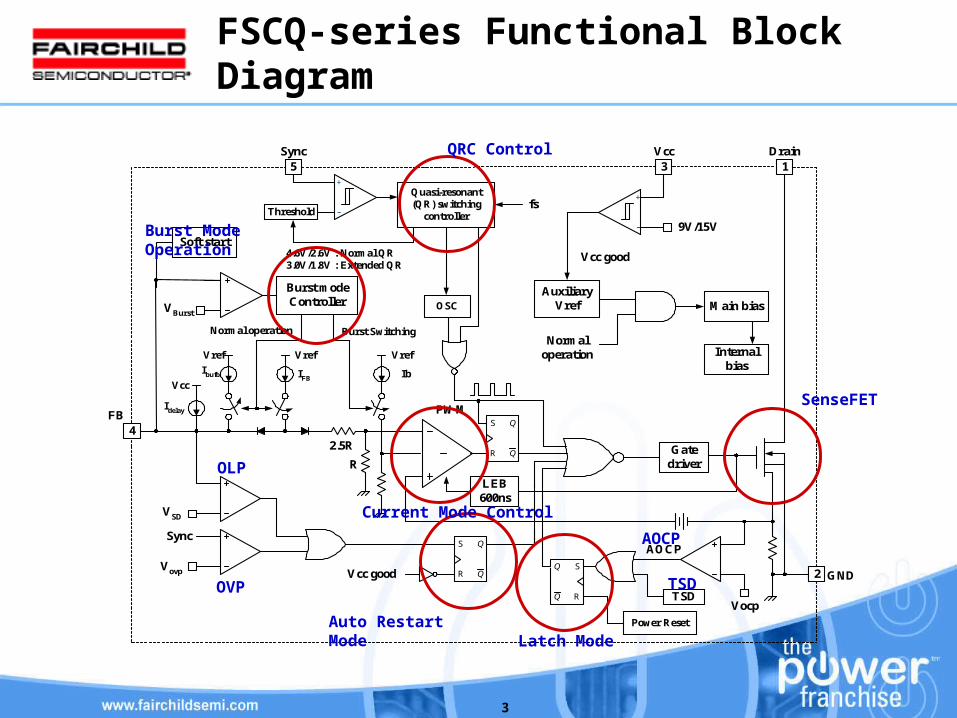
FSCQ-series Functional Block Diagram
9V/15V
3 1
2
4
AuxiliaryVref Main bias
S
Q
Q
R
OSC
Vcc
Vref
Idelay
IFB
VSD
TSD
Vovp
Sync
Vocp
S
Q
Q
R
R
2.5R
Vcc good
Vcc Drain
FB
GND
AOCP
Gatedriver
Vcc good
LEB600ns
PWM
Soft start
Internalbias
Normaloperation
VBurst
Vref
Ib
Vref
Ibufb
Burst modeController
Normal operation Burst Switching
5Sync
Threshold
Quasi-resonant(QR) switching
controller
+
-
+
-
S
Q
Q
R
Power Reset
4.6V/2.6V : Normal QR3.0V/1.8V : Extended QR
fs
QRC Control
Burst Mode Operation
TSD
OLP
OVP
AOCP
Latch Mode
Current Mode Control
Auto Restart Mode
SenseFET
4
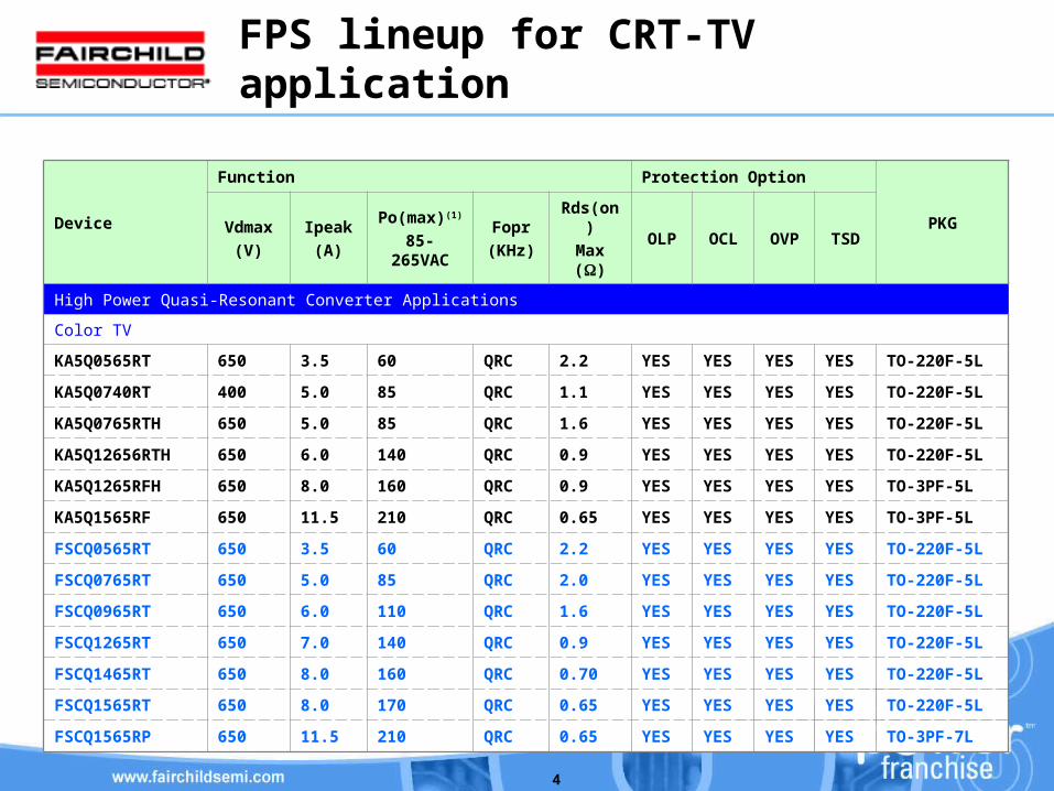
FPS lineup for CRT-TV application
Device
Function Protection Option
PKGVdmax
(V)
Ipeak
(A)
Po(max)(1)
85-265VAC
Fopr
(KHz)
Rds(on)
Max ()OLP OCL OVP TSD
High Power Quasi-Resonant Converter Applications
Color TV
KA5Q0565RT 650 3.5 60 QRC 2.2 YES YES YES YES TO-220F-5L
KA5Q0740RT 400 5.0 85 QRC 1.1 YES YES YES YES TO-220F-5L
KA5Q0765RTH 650 5.0 85 QRC 1.6 YES YES YES YES TO-220F-5L
KA5Q12656RTH 650 6.0 140 QRC 0.9 YES YES YES YES TO-220F-5L
KA5Q1265RFH 650 8.0 160 QRC 0.9 YES YES YES YES TO-3PF-5L
KA5Q1565RF 650 11.5 210 QRC 0.65 YES YES YES YES TO-3PF-5L
FSCQ0565RT 650 3.5 60 QRC 2.2 YES YES YES YES TO-220F-5L
FSCQ0765RT 650 5.0 85 QRC 2.0 YES YES YES YES TO-220F-5L
FSCQ0965RT 650 6.0 110 QRC 1.6 YES YES YES YES TO-220F-5L
FSCQ1265RT 650 7.0 140 QRC 0.9 YES YES YES YES TO-220F-5L
FSCQ1465RT 650 8.0 160 QRC 0.70 YES YES YES YES TO-220F-5L
FSCQ1565RT 650 8.0 170 QRC 0.65 YES YES YES YES TO-220F-5L
FSCQ1565RP 650 11.5 210 QRC 0.65 YES YES YES YES TO-3PF-7L

5
KA5Q series V.S FSCQ-series
Generation KA5Q-Series FSCQ-Series FSCQ Advantages
Control MethodQRC/PSR
High Efficiency/Low EMI
QRC with high frequency limit
High Efficiency/Low EMI
Temp. of device can be lower at high line input
Start-up current
/Operation current
Max. 200uA
/ 18mA(always constant)
Max. 50uA
/ 6mA(reduced in burst mode)
Lower standby power
Output regulation in standby
By Vcc control By Feedback control Just difference of method
Output voltage drop in standby
About half Any levelLower standby power but
MCU reset must be considered
Standby power Under 2W Under 1W
Soft start None 20mSReducing stress on Power
MOSFET & transformer
SenseFET Q-FET S-FET
PKG TO220F-5L/TO3PF-5L TO220F-5L/TO3PF-7LSame PCB pattern can be
used for different PKG

6
Power Consumptions in standby mode

7
Typical Application circuit
C10310uF50V
1
3
4
10
T1EER3540
12V, 1A
C2041000uF
35V
D205EGP20D
11
LF101
C101330nF
275VAC
FUSE250V3.0A
C102220uF400V
RT1015D-9
BD101
D1011N4937
R1035.1Ω
0.25W
6
7
R1041.5kΩ0.25W2 4
5
1
3
GND
DrainSYNC
FB
Vcc
D1031N4148
IC101FSCQ0765RT
C10647nF50V
R105470Ω0.25W
C1053.9nF50V
ZD10118V1W
C1071nF1kV
BEAD101
D1021N4937
C210470pF
1kV
18V, 0.5A
D204EGP20D
C2051000uF
35V
13
C209470pF
1kV12
125V, 0.4A
D202EGP20J
C201100uF160V
14
C207470pF
1kV
L201BEAD
16
C20247uF160V
24V, 0.5A
D203EGP20D
C2031000uF
35V
17
C208470pF
1kV18
OPTO101817A
R2011kΩ
0.25W
C20622nF50V
C3012.2nF
Q201KA431
R20339kΩ0.25W
R2021kΩ
0.25W
R205220kΩ0.25W
R2044.7kΩ0.25W
VR20130kΩ
D201Q202
KSC945 R2065.1kΩ0.25W
R2075.1kΩ0.25W
SW 201
15
R102120kΩ0.25W
R101120kΩ0.25W
R1061kΩ1W
C10410uF50V
ZD2025.1V0.5W
R2081kΩ
0.25W
Normal
Standby
D104UF4007
8
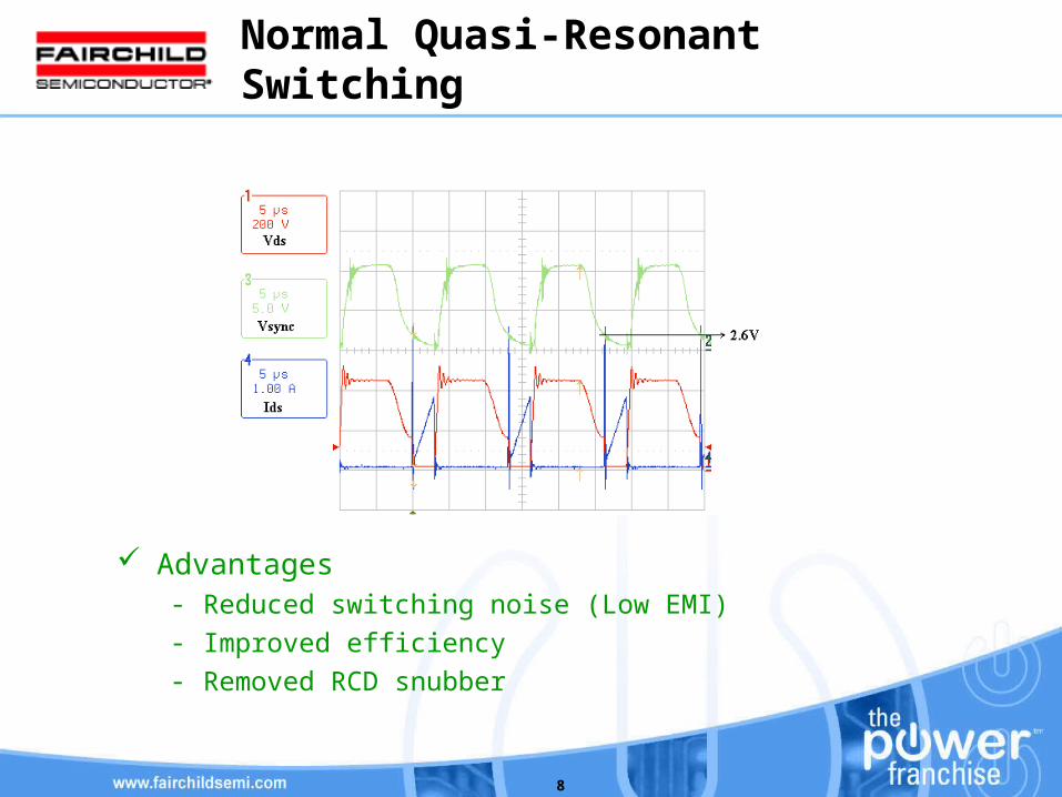
Normal Quasi-Resonant Switching
Advantages- Reduced switching noise (Low EMI)
- Improved efficiency
- Removed RCD snubber

9
Normal Quasi-Resonant Switching
Limitations- Intermittent switching at light load due to a relatively large LEB time- Increased switching loss at light load
Vds
Ids
Vds
Ids
Output power
Switching frequency
Light load
Heavy load

10
Extended Quasi-Resonant Switching
Advantages- Guarantee stable operation over wide load range
- Improve efficiency at light load condition
Output power
Switchingfrequency
Normal QR Switching
Extended QR Switching
90kHz
45kHz
11
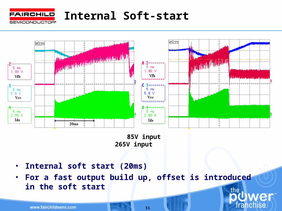
Internal Soft-start
• Internal soft start (20ms)• For a fast output build up, offset is introduced in the soft start
85V input 265V input

12
Over load Protection - Output short
85V input 265V input
13
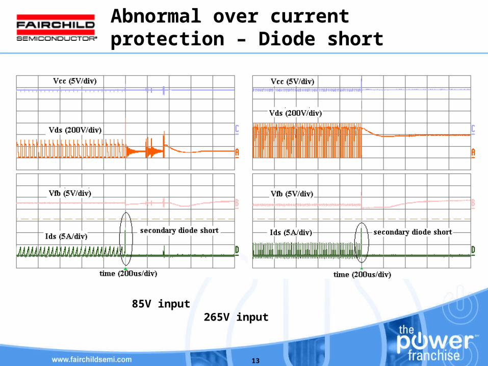
Abnormal over current protection – Diode short
85V input 265V input
14
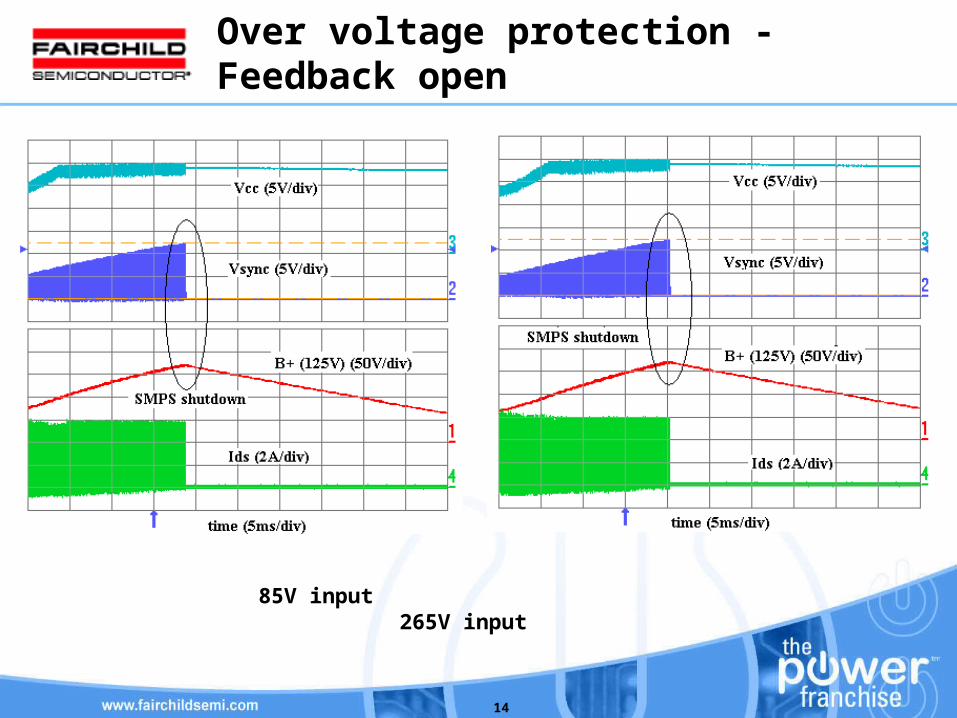
Over voltage protection -Feedback open
85V input 265V input
15
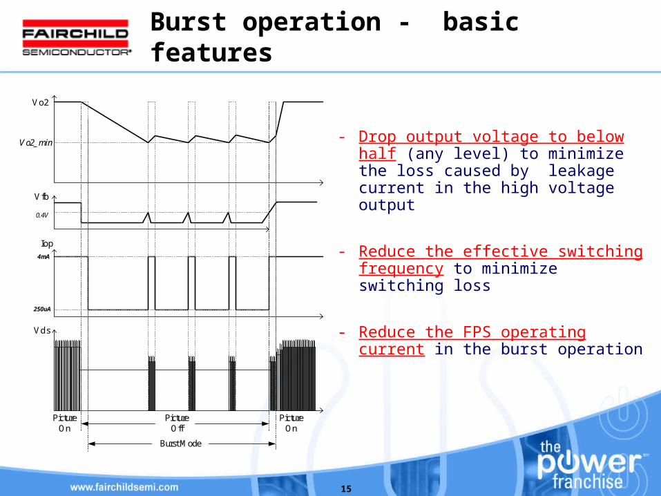
Burst operation - basic features
Vo2
Vfb
Iop
Vds
0.4V
Vo2_min
4mA
PictureOn
PictureOff
PictureOn
Burst Mode
250uA
- Drop output voltage to below half (any level) to minimize the loss caused by leakage current in the high voltage output
- Reduce the effective switching frequency to minimize switching loss
- Reduce the FPS operating current in the burst operation

16
Burst operation - Output drop circuit
Picture ON
MicomLinearRegulator
VO2
VO1 (B+)
KA431R2
R1
R3
Rbias
RD
RFCF D1Q1
A
CR
Dz
- Normal mode : Vo1 (B+) is regulated
- Standby mode : Vo2 is regulated

17
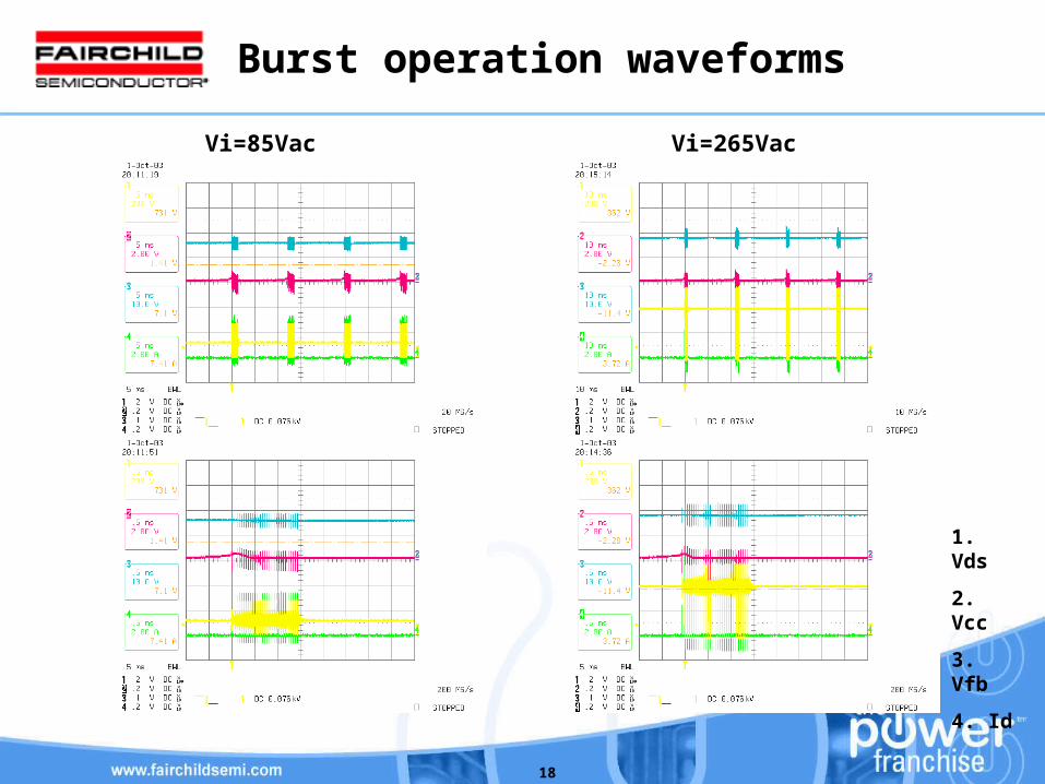
Burst operation waveforms
Normal Standby Standby Normal
18
Burst operation waveforms
Vi=85Vac Vi=265Vac
1. Vds
2. Vcc
3. Vfb
4. Id