www 3 cycle . ElectricalPartManuals Best-Selling Breaker In Its Class Of all the SF6 circuit...
12
SIEMENS Type SP and SPS Puffer Circuit Breaker 15.5 - 72.5 kV 1200,2000 and 3000A 20,31.5 and 40 3 cycle www . ElectricalPartManuals . com
Transcript of www 3 cycle . ElectricalPartManuals Best-Selling Breaker In Its Class Of all the SF6 circuit...

SIEMENS
Type SP and SPS Puffer Circuit Breaker 15.5 - 72.5 kV 1200,2000 and 3000A
20, 31.5 and 40 kA 3 cycle
www . El
ectric
alPar
tMan
uals
. com
The Best-Selling Breaker In Its Class
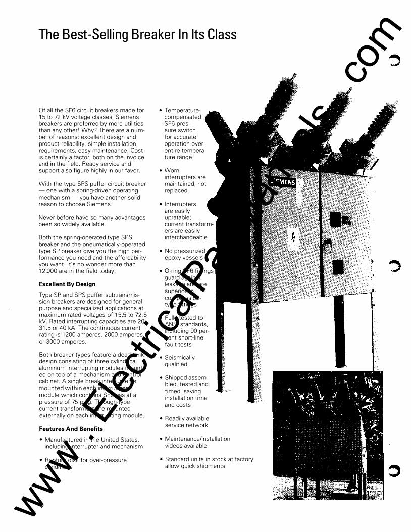
Of all the SF6 circuit breakers made for 1 5 to 72 kV voltage classes, Siemens breakers are preferred by more utilities than any other! Why? There are a number of reasons: excellent design and product reliability, simple installation requirements, easy maintenance. Cost is certainly a factor, both on the invoice and in the field. Ready service and support also figure highly in our favor.
With the type SPS puffer circuit breaker - one with a spring-driven operating mechanism - you have another solid reason to choose Siemens.
Never before have so many advantages been so widely available.
Both the spring-operated type SPS breaker and the pneumatically-operated type SP breaker give you the high performance you need and the affordability you want. It's no wonder more than 12,000 are in the field today.
Excellent By Design
Type SP and SPS puffer subtransmission breakers are designed for generalpurpose and specialized applications at maximum rated voltages of 15.5 to 72.5 kV. Rated interrupting capacities are 20, 31.5 or 40 kA. The continuous current rating is 1200 amperes, 2000 amperes or 3000 amperes.
Both breaker types feature a dead tank design consisting of three cylindrical aluminum interrupting modules mounted on top of a mechanism and control cabinet. A single break interrupter is mounted within each interrupting module which contains SF6 gas at a pressure of 75 psig. Through-type current transformers are mounted externally on each interrupting module.
Features And Benefits
• Manufactured in the United States, including interrupter and mechanism
• Rupture disk for over-pressure conditions
2
• Temperaturecompensated SF6 pressure switch for accurate operation over entire temperature range
• Worn interrupters are maintained, not replaced
• Interrupters are easily upratable; current transformers are easily interchangeable
• No pressurized epoxy vessels
• 0-ring SF6 fittings guard against leakage and are superior to compressiontype fittings
• Fully tested to ANSI standards, including 90 percent short-line fault tests
• Seismically qualified
• Shipped assembled, tested and timed, saving installation time and costs
• Readily available service network
• Maintenance/installation videos available
• Standard units in stock at factory allow quick shipments
www . El
ectric
alPar
tMan
uals
. com

The Interrupting Module
Each interrupting module contains SF6 We designed the A gas at a pressure of 75 psig, along with interrupters to make a single break interrupter housed in a inspections easy, with a glass-epoxy filament-wound tube. bolted cover providing Energy for interrupting fault current is quick access to the provided by an opening spring within the assembly. control cabinet. Through this opening spring pressure, the interrupter momen- And because interrupters tarily increases SF6 gas pressure in the are mechanically inter-space between parting contacts in the changeable, the SP and interrupter, extinguishing the arc. SPS breakers can be I
Arcing Here's how it works: field-uprated through all Contact
(20, 31.5, 40 kA) ratings. Each interrupter unit contains a stationary current-carrying contact, an arcing horn, a moving contact and gas-compressing piston, a Teflon inter-rupting chamber and current-carrying finger contacts. So all three phases operate simultaneously, all moving contacts are mechanically linked. A Interrupter Assembly
Closed In the closed position, current is trans-ferred from the bushing conductor to B Interrupter Assembly c
., the moving contact. From the piston of Partially Open the moving contact, the current travels to stationary main contact fingers and C Interrupter Assembly exits the interrupter assembly through Open the other bushing.
On opening, the moving contact sepa-rates from the stationary contact fingers, transferring the arc to the moving and stationary arcing contacts.
Energy for opening is stored in the tail spring. When tripped, this spring trans-mits its energy to a single horizontal Typical Single Phase Pole Unit
Bushing linkage located in the cabinet. Motion is then transferred to operating rods and moving contacts.
Current
The moving contact piston compresses Transformer
the SF6 gas. When the arcing contacts part. compressed gas flows along the arc and hot gases sweep through the center of the moving and stationary contacts until interruption occurs. Inspection
Cover At the end of this sequence, the SF6 gas reverts back to the steady state pressure of 75 psig, ready for the next operation. Shaft Seal
Assembly
Interrupter
3 www . El
ectric
alPar
tMan
uals
. com

Bushing Current Transformers
Only porcelain weathercases are used on the Siemens SP and SPS models. The reasons are simple: long life, low maintenance, low repair requirements.
Porcelain offers key maintenance benefits because it's highly resistant to all weather conditions. And porcelain has a proven field record for dependability and reliability.
Six standard 50" creepage bushings are provided on SP and SPS type breakers. To accommodate special needs, optional designs may be ordered. For instance, insulators are available for altitudes to 10,000 feet. as are extra creep designs suitable for high contamination zones. SP and SPS bushings are also manufactured to withstand a cantilever mechanical load of up to 150 pounds.
Bushings are mechanically interchangeable. This means that 1200 amp breakers can easily be uprated to 2000 and 3000A.
Bushing Current Transformers External bushing current transformers are mounted in weatherproof housings on both sides of the breaker. Their leads terminate in the control cabinet at short circuiting type terminal blocks. Space is available for mounting two current transformers per bushing.
Ratio CD 600:5 M R
6005 M R
1200:5 MR
1200:5 MR
2000:5 MR
2000:5 MR
3000:5 MR
300:5 S R
600:5 S R
600/1200:5 DR
1200:5 S R
2000:5 S R
CD Ratio
4
MR = Multiple Ratio
SR = Single Ratio
DR = Dual Ratio
Accuracy(?) C-100
C-200
C-200
C-400
C-400
C-800
C-800
0.6B-0.5
0.3B-0.5
0.3B-0.5/0.3B-1.0
0.3B-1. 0
0.3B-2. 0
C?J Accuracy
C = Relay Accuracy
B = Meter Accuracy
Siemens gives you the flexibility of choosing any combination of relaying
type, metering accuracy or linear couplers- multi-ratio, single
ratio, or dual ratio. If you need to change the
combination later, it's no problem; there's minimal time and expense involved.
www . El
ectric
alPar
tMan
uals
. com

Gas Handling System
When you first install it, and later, whenever you inspect it, you'll find there's minimal gas handling associated with the Siemens SF6 puffer breaker. Thanks to a design that features low gas pressure and volume (just 15.0 pounds) , you can forget about the complications of gas carts, vacuum pumps, tank filters and special drying equipment
The breaker is shipped with 5 psig of positive pressure, so there's no need to evacuate the pole unit for installation. Another advantage to this shipping method? It provides a double check for possible leakage.
To transfer gas into the common gas system, you simply connect a bottle of SF6 to the fill valve located in the control cabinet No vacuum pumps or gas carts are required. With the fill valve opened, gas is completely transferred to the interrupters, up to 80 psig at 70'F (20'C), as indicated on the pressure gauge.
While not standard on puffer breakers from some manufacturers, Siemens SP and SPS models have an SF6 rupture disc to automatically relieve any pole unit overpressure condition. This important feature can prevent catastrophic breaker damage in the event of a sustained, internal fault The rupture disc is located on each inspection cover, shielded by a deflector plate to prevent possible injury to personnel.
For easy accessibility, interrupter pole
,, units are at ground potential. And each individual pole unit has a "quick disconnect" coupling so that it can be isolated for easy installation and servicing.
There's no need for special drying equipment either. The low gas volume permits potential moisture problems to be handled with a small desiccant bag inserted in the interrupter housing.
The breaker can be timed externally, without disturbing the SF6 environ
ment. Internal inspections are kept to a minimum- only one fourth the number usually required. That's because Siemens tests and verifies its interrupters for 20 full-rated fault interruptions.
Quick disconnect coupling
5 www . El
ectric
alPar
tMan
uals
. com
Spring Charged Operating Mechanism
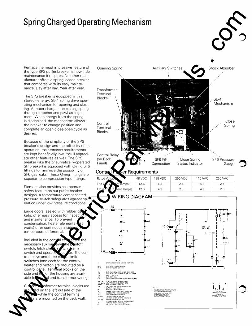
Perhaps the most impressive feature of the type SPS puffer breaker is how little maintenance it requires. No other manufacturer offers a spring loaded breaker that compares with its easy maintenance. Day after day. Year after year.
The SPS breaker is equipped with a stored - energy, SE-4 spring drive operating mechanism for opening and closing. A motor charges the closing spring through a ratchet and pawl arrangement. When energy from the spring is discharged, the mechanism allows the breaker to change position and complete an open-close-open cycle as desired.
Because of the simplicity of the SPS breaker's design and the reliability of its operation, maintenance requirements are kept beneficially low. You'll appreciate other features as well. The SPS breaker (like the pneumatically-operated SP breaker) is equipped with 0-ring SF6 fittings to minimize the possibility of SF6 gas leaks. These 0-ring fittings are superior to compression-type fittings.
Siemens also provides an important safety feature on our puffer breaker designs. A temperature compensated pressure switch safeguards against operation under low pressure conditions.
Large doors, sealed with rubber gaskets, offer easy access for inspection and maintenance. To prevent condensation, heater elements (125 watts) offer continuous inside/outside temperature differential.
Included in the control cabinet are the necessary auxiliary switches, cutoff switch, latch check switch, alarm switch and operation counter. The control relays and three control knife switches (one each for the control, heater and motor) are mounted on a control panel. Terminal blocks on the side and top of the housing are available for control and transformer wiring.
Current transformer terminal blocks are mounted on the left outside of the housing while the control terminal blocks are mounted on the back wall.
6
Opening Spring
Transformer Terminal Blocks
Control Terminal Blocks
Control Relay (on Back Panel)
SF6 Density Switch
Auxiliary Switches
SF6 Fill Connection
Close Spring Status Indicator
Shock Absorber
SE-4 Mechanism
Close Spring
SF6 Pressure �. Gauge �
Control Power Requirements Rated Voltage 48VDC 125 VDC 250 VDC 115VAC 230 VAC
Trip Coil Current lamps) 12.6 4.3 2. 6 4.3 2.6
Close Coil Current lamps) 12. 6 4.3 2.6 4.3 2.6
WIRING DIAGRAM----------------,
BREAKER CONTROL SWITCH IRE MOTEl
08-1 CONTROL POWER SWITCH 08--3 MOTOR POWER SWITCH
52a BKR. AUX. SW -OPEN WHEN BKR OPEN 52b BKR AUX. SW -CLOSED WHEN BKR OPEN 52C BKR CLOSE COIL 52T BKR TRIP COIL 52Y BKR CLOSING CUTOFF RELAY !ANTI-PUMP)
LOW PRESSURE ALARM-{SF61 LOW PRESSURE CUTOUT-ISF61 MOTOR STARTER RELAY
INTERRUPTER SF6 LOW PRESSURE CUTOUT AUX RElAY
88 MOTOR {120 VAc OPTIONAL G GREEN INDICATOR LIGHT {REMOTE) LCC CLOSE LATCH CHECKING SWITCH LCT LATCH CHECKING SWITCH LCS--CC SPRING CHARGE SWITCH
{CLOSED WHEN SPRING CHARGED!
LCS-MS SPRING CHARGE-SWITCH {CLOSED WHEN SPRING DISCHARGED!
PR REMOTE PROTECTIVE RELAY
R RED INDICATOR LIGHT !REMOTE)
J OOG L SW#2 TEO
45 -�46 l:', T 1_f,,'l L--------------------;o
1 ALL EQUIPMENT SHOWN WITH CIRCUIT BREAKER OPEN CONTROL VOLTAGE OFF SF6PRESSURELOW
SPRING DISCHARGED
� LOWSF6
PRESSURE ALARMS
www . El
ectric
alPar
tMan
uals
. com

As shown in Fig. 1, the closing spring is discharged and the breaker is in the open position. Before a closure can be initiated, Spring A must be charged. This is accomplished by a motor (1) with a ratchet arm (2), which imparts motion to a wheel (3) within the mechanism. The wheel turns (CCW) until Spring A is charged.
To Spring B (opening)
Fig. 2 shows the mechanism with 2 Spring A charged and the breaker in the open position. The close latch (4) sup-ports the closing spring's stored energy. To close the breaker, the close release latch (5) is rotated, releasing the close latch and allowing Spring A to discharge.
As illustrated in Fig. 3, when Spring A discharges, the breaker changes to the closed position, and the opening Spring B (not shown) is charged. The mechanism is now ready to open. The spring
""' charging motor now starts and recharges the closing Spring A as shown in Fig. 4.
The opening Spring B pressure is supported by the trip latch (6). To open the mechanism, the open release latch (7) is rotated. This releases the trip latch and allows the opening Spring B (not shown) to discharge.
When the opening Spring B discharges, the breaker opens and is in the position shown in Fig. 2.
Fig.1 Spring discharged breaker open
Fig. 3 Spring discharged breaker closed
To Spring B (opening)
Fig. 2 Spring charged breaker open
Fig. 4 Spring charged breaker closed 7 www .
Elec
tricalP
artM
anua
ls . c
om

Pneumatic Operating Mechanism
The pneumatic operation of the Siemens type SP puffer breakers is field proven and customer acclaimed. With good reason. Even during power outages, when the ac control power to the compressor is lost. the operator can allow five closeopen operations (COs). You can definitely count on its reliability.
The type SA-7 mechanically and electrically trip-free pneumatic mechanism is used on the SP breaker. During a sustained fault. the time that the fault current is on the system during a reclosing operation is minimized. The pneumatic operation assures uniform pressure throughout the complete closing stroke. Breaker operation is smooth.
The SA-7 is ideally suited for high-speed reclosing. Reclosing times of 20 cycles, from the instant of initial tripping impulse until the current is re-established, are common. Some customers report even faster closing times.
Each mechanism is complete with its own storage reservoir, motor-driven
Opening Spring
Control Terminal Blocks
Compressor Motor
Transformer Terminal Blocks
Pressure Switches
Compressor
SF6 Density Switch
SF6 Pressure
Gauge
Shock Absorber
Mechanism
Auxiliary Switch
Drain Valve
Safety Valve
compressor, pressure switches, pres- Control Power Requirements sure gauge and safety valve to prevent excessive pressures. A drain valve is provided to remove condensed moisture from the reservoir. The air tank meets all A.S.M.E. requirements.
Large doors, sealed with rubber gaskets, offer easy access to the weatherproof control cabinet during inspection and maintenance. To prevent condensation, heater elements (825 watts) offer continuous inside/outside temperature differential.
And to keep your parts requirements low, all control cabinet parts are interchangeable in all ratings from 15kV to 72kV, 20kA to 40kA and 1200 amps to 3000 amps.
8
Rated Voltage 24 VDC 48VDC 125 VDC 250 VAC 115VAC 230 VAC
Trip Coil Current (amps) 45.0 24.0 6.6 9.9 6.6 6.6
Close Co1l Current (amps) 2.5 5. 0 1. 1 2.0 1.1 2.0
,.--- WIRING DIAGRAM ----------------,
08 Control Power Sw1tch 52a Bkr. Aux. Sw.-Open When Bkr. Open 52b Bkr Aux Sw.- Closed When Bkr. Open 52AA Mech. Aux. Sw. ·Open When Skr. Open 5288 Mech. Aux. Sw -Closed When Bkr. Open 52X Bkr. Closmg Relay 52Y Bkr. Closing Cutoff Relay 52C Bkr Close Valve Coil 52T Bkr Trip Coil 52 LC Latch CheckSWi!Ch 63G-LPA Low Pressure Alarm-(Gas) 63G-LPC Low Pressure Cutout- (Gas) 63C Low Pressure Cutout -(Air) 63A Low Pressure Alarm -(Air) 63X Interrupter Gas Low Pressure
Cutout Aux Relay 01 Remote Control Sw1tch PR Remote Protective Relays
Auxiliary Switches Shown For Open Bkr Relay Contacts Shown De-Energized A1r Pressure Sw's Shown For Low Pressure Gas Pressure Sw's Shown For Low Pressure
" " " �------------r-"f-r-1 4.-l,rJ 11= 1 1 I I 1 1
63G LPA : I 11
I �A .l.m.l.PR � -� R.l.y•TT PRESSURE ALARMS 1 T 1 Go 1 1 1 ' " r,;-;;-n) i- n " L+J
-- ---.L5 t 11
f63G r: �>4' .� . �: � r I "
I � �5C 58 X
r',' I n
- � '+-! l l l t'� l
www . El
ectric
alPar
tMan
uals
. com

.......
Dimensions
Type
Voltage Cont. A Current SP/SPS-15.5 1200/2000 63.2
SP/SPS-15.5 1200/2000 73.9
SP/SPS-15 5 2500/3000 83.8
SP/SPS-25.8 1200/2000 63.2
SP/SPS-25 8 1200/2500 73.9
SP/SPS-25.8 2500/3000 83.8
SP/SPS-38 1200/2000 63.2
SP/SPS-38 1200/2000 73.9
SP/SPS-38 2500/3000 83.8
SP/SPS-48.3 1200/2000 63.2
SP/SPS-48.3 1200/2000 73.9
SP/SPS-48.3 2500/3000 83.8
SP/SPS-72.5 1200/2000 63.2
SP/SPS-72.5 1200/2000 73.9
SP/SPS-72.5 2500/3000 83.8
SP/SPS-72.5 2500/3000 94.3
Dimensions only for reference,
not for construction purposes .
Between
L1ve Parts
Travel Recorder
Connection
Pos1t1on lnd1cator {SP only)
50
Cover
B c
119.1 123.7
124.9 128.6
119.1 133.0
119.1 123.7
124.9 128.6
119.1 133.0
119.1 123.7
124.9 128.6
119.1 133.0
119.1 123.7
124.9 128.6
119.1 133.0
126.6 131.2
124.9 128.6
126.6 140.5
124.9 137.9
6
Dimensions (inches) Weight (lbs)
D E F G H Creep Breaker SF6
97.00 29.1 136.4 33.5 270 50.0 3185 15
102.0 35.0 142.2 33.5 27.0 73.0 3250 15
107.0 39.7 147.5 33.5 23.5 50.0 3285 15
97.0 29.1 136.4 33.5 27.0 50.0 3185 15
102.0 35.0 142.2 33.5 27.0 73.0 3250 15
107.0 39.7 147.5 33.5 23.5 50.0 3285 15
97.0 29.1 136.4 33.5 27.0 50.0 3185 15
102.0 35.0 142.2 33.5 27.0 73.0 3250 15
107.0 39.7 147.5 33.5 23.5 50.0 3285 15
97.0 29.1 136.4 33.5 27.0 50.0 3185 15
102.0 35.0 142.2 33.5 27.0 73.0 3250 15
107.0 39.7 147.5 33.5 23.5 50.0 3285 15
97.0 29.1 143.9 41.0 27.0 50.0 3185/3455* 15
102.0 35.0 142.2 33.5 27.0 73.0 3250/3520* 15
107.0 39.7 154.9 41.0 23.5 50.0 3285/3555* 15
112.0 46.1 153.3 33.5 23.5 73.0 3350/3620* 15
*Includes capacitor for 40kA
Breaker weights include 6 CTs. Add 120 lbs. for each addit1onal CT.
{4) Lrftrng Lugs
Current Transformer
SF6 Pressure Gauge & Operation
Counter D
14.5
1.500-12 THD
Window Shrp Ht
Air
c
Bush1ng Removal
Live Part
B
Ground Pad on Near & Far Srde Wrth 121
500-13 Tapped Holes
9 www . El
ectric
alPar
tMan
uals
. com
Controls and Relays
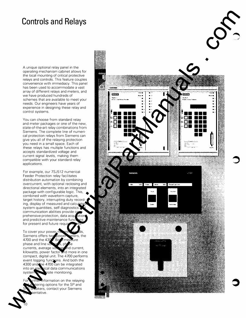
A unique optional relay panel in the operating mechanism cabinet allows for the local mounting of critical protective relays and controls. This feature couples convenience with immediacy. This panel has been used to accommodate a vast array of different relays and meters, and we have produced hundreds of schemes that are available to meet your needs. Our engineers have years of experience in designing these relay and control systems.
You can choose from standard relay and meter packages or one of the new, state-of-the-art relay combinations from Siemens. The complete line of numerical protection relays from Siemens can give you all of the relaying protection you need in a small space. Each of these relays has multiple functions and accepts standardized voltage and current signal levels, making them compatible with your standard relay applications.
For example, our 7SJ512 numerical Feeder Protection relay facilitates distribution automation by combining overcurrent. with optional reclosing and directional elements, into an integrated package with configurable logic. This, combined with waveform capture, target history, interrupting duty recording, display of measured and calculated system quantities, self diagnostics and communication abilities provide comprehensive protection, data acquisition and predictive maintenance functions for present and future requirements.
To cover your power metering needs, Siemens offers two power meters, the 4700 and the 4300. Both measure phase and line voltages, phase currents, average voltage and current. kilowatts, power factor and more in one compact. digital unit. The 4700 performs event logging functions. And both the 4300 and the 4700 can be integrated into an electrical data communications system for remote monitoring.
For further information on the relaying and metering options for the SP and SPS breakers, contact your Siemens representative.
10
•• ••• c• ••• c• ••• c• •••
... �
•• ��- I
���
ii :'<> •• ••• .. c• •••
c• ••• c• •••
••• ••
www . El
ectric
alPar
tMan
uals
. com

Ratings and Specifications
Identification Ratings
Voltage Insulation
Rated Type Nominal Rated Voltage Low
kV Max Range Freq. Impulse Class kV Factor (kV, rmsl (kV, Crestl
SP/SPS-15.5-31.5 14.4 15.5 1.0 50 110 SP/SPS-15.5-40 14.4 15.5 1.0 50 110 SP/SPS-25.8-20 23.0 25.8 1.0 60 150 SP/SPS-25.8-31.5 23.0 25.8 1.0 60 150 SP/SPS-25.8-40 23.0 25.8 1.0 60 150 SP/SPS-38-20 34.5 38.0 1.0 80 200 SP/SPS-38-31.5 34.5 38.0 1.0 80 200 SP/SPS-38-40 34.5 38.0 1.0 80 200 SP/SPS-48.3-20 46.0 48.3 1.0 105 250 SP/SPS-48.3-31.5 46.0 48.3 1.0 105 250 SP/SPS-48.3-40 46.0 48.3 1.0 105 250 SP/SPS-72.5-20 69.0 72.5 1.0 160 350 SP/SPS-72.5-31.5 69.0 72.5 1.0 160 350 SP/SPS-72.5-40 69.0 72.5 1.0 160 350
Supplementary Specifications Voltage
DESCRIPTION UNIT SP/SPS SP/SPS SP/SPS SP/SPS SP/SPS 15.5 25.8 38 48.3 72.5
L(JI.,htning Impulse ithstand Voltage
Chopped Wave 2ps kV 142 194 258 322 452 Chopped Wave 3ps kV 126 172 230 288 402
Rated Normal Current (10'1 A 12/20/30 12/20/30 12/20/30 12/20/30 12/20/30 Normal Frequency Hz 60 60 60 60 60 Optional Frequency Hz 50 50 50 50 50 Rated Permissible Tripping Delay (Y) s 2 2 2 2 2 Auxiliary Voltage Vac 115/230 �erating
echanism - Spring ("OCO")/Pneumatic (5 "CO") Pneumatic Pressure psig 190 INA Spring Mech.) Air Compressor Motor hp 0.75 INA Spring Mech.l Trip Coils Single (standard) - Dual (option all
TriP. and Close Coil Rating Vdc 48/125/250
Breaks Per Phase - 1
Contact Gap in 4.5
Phase Spacing in 30.5
Seismic Withstand Standard g 0.3 Dynamic Optional g 0.5 Dynamic
Rated Voltage Range Factor (k) 1.0
RIV at 1000 kHz pV «500
Related Capabilities
Current- Amperes Current Values -Amperes
Rated Maximum 3-Sec. Rated Short Circuit Interrupting Symmet- Short Time Closing
Continuous Current Time rica I Current and at60 at Rated (Cyclesl Interrupting Carrying Latching
Cycles Max. kV Capability Capability Capability
1200/3000 31,500 3 31,500 31,500 50,000 1200/3000 40,000 3 40,000 40,000 64,000 1200/3000 20,000 3 20,000 20,000 32,000 1200/3000 31,500 3 31,500 31,500 50,000 1200/3000 40,000 3 40,000 40,000 64,000 1200/3000 20,000 3 20,000 20,000 32,000 1200/3000 31,500 3 31,500 31,500 50,000 1200/3000 40,000 3 40,000 40,000 64,000 1200/3000 20,000 3 20,000 20,000 32,000 1200/3000 31,500 3 31,500 31,500 50,000 1200/3000 40,000 3 40,000 40,000 64,000 1200/3000 20,000 3 20,000 20,000 32,000 1200/3000 31,500 3 31,500 31,500 50,000 1200/3000 40,000 3 40,000 40,000 64,000
Current* DESCRIPTION UNIT 20kA 31.5kA 40kA
Rated Short Circuit Current kA 20 31.5 40 Rating Making Current kA 20 31.5 40 Closing and Latching Capability
rms kA 32 50 64 peak kA 54 85 108
Capacitance Switching
General Pu�ose Overhea Line A 100 Isolated Current A 250
Definite Pu�ose Overhea Line A 100 Isolated Current A 630
Asymmetrical Int. Capability Ratio (S) - 1.2 Normal Operating Temperature Range
Standard 'C -30'C to 40'C Special 'C -40'C/-50'C to 40'C
Closing Time (totall ms 100 Rated Reclosing Time Cycles 20 Rated Duty Cycle - OC0-15S-CO (No derating) External Creep
I I Standard in 50.5 50.5 50.5 Special in 73 73 73
External Strike To Ground
I I Standard in 19 19 19 Special in 29 29 29
Oty. SF6 lbs 15 SF6 Pressure psig 75 © 70° F/20° C
11 www . El
ectric
alPar
tMan
uals
. com

Getting The Best Breaker For Your Needs
In considering any circuit breaker, today's utilities must be concerned not only with initial price and installation, but also with the ongoing costs of ownership. The Siemens SP and SPS win in every category. Their relatively low price tag, simple installation, and easy maintenance will continue to pay dividends decades into the future.
In addition, both standard-type breakers can be used for a number of special requirements, such as:
• Switching capacitors, cables and reactors
• Environmentally restricted sites requiring oil sumps
• System stability problems requiring three-cycle interrupting
• Reclosing duty without de-rating interrupting capability
• High contamination zones that require extra creep and low contamination weather sheds
• High altitude application up to 10,000 feet without de-rating
How To Order
When ordering a Type SP or Type SPS breaker, specify the following:
1. Breaker type and rating 2. Trip voltage: refer to pages 6, 8 3. Close voltage: refer to pages 6, 8 4. Motor voltage: 115, 230 Vac (SP)
120 Vac/125 Vdc, 240 Vac/250 Vdc (SPS)
5. Heater voltage: 115, 230 Vac 6. BCTs: type, ratio, number, location 7. Terminals: specify in detail if desired 8. Relays: specify in detail if desired 9.1nclude customer specifications
covering special equipment accessories, tests, etc.
Basic Breaker
The standard basic breaker includes:
1. Three-pole SF6-filled outdoor power circuit breaker with three SF6 interrupters.
2. Set of four structural steel legs. 3. Light gray standard color. 4. Six light gray SF6 filled bushings. 5. Six relaying accuracy bushing
current transformers. 6. Trip-free spring or pneumatic
operating mechanism. ?. Instrumentation to monitor
SF6 gas pressure and provide low pressure alarm.
8. Eleven stage auxiliary switch; eight stages for customer use.
9. Trip coil and close coil. 1 O. Cabinet heater to prevent
condensation. 11. Necessary terminal blocks and
wiring. 12.0perations counter. 13. Fused knife switches (3). 14.Grounding pads (2). 15.Mechanical position indicator. 16. Provision for travel recorder
attachment.
17. Fifteen pounds of SF6 gas. 18.Set of special hand tools required
for installing SP breakers provided for each station.
Optional Modifications
1. Extra BCTs. 2. Metering accuracy BCTs. 3. Extra creepage bushings. 4. Capacitor trip. 5. Relays for reclosing or non
reclosing breaker application. 6. External pull to trip handle. 7. Cabinet light and convenience
outlet. 8. Special heaters and cabinet insulation
for operation down to -50T. 9. One or two additional 11-pole
auxiliary switches. 10. Dual trip coils. 11. 50 Hertz operation.
Siemens Energy & Automation � Technology that serves the customer. .._.;} The information contained herein is general in nature and is not intended for specific construction, installation or application purposes. Siemens Energy & Automation, Inc. reserves the right to make changes in specifications shown herein or add improvements at any time without notice or obligation
Siemens Energy & Automation, Inc. Power Products Division
P 0 Box 6289 Jackson. MS 39288-6289 (601) 939-0550 FAX:(601) 939-3606 ©1993 Siemens Energy & Automation, Inc. All rights reserved. SIEMENS is a registered trademark of Siemens AG.
Bulletin PB 3506-0210M1293GA
Pnnted in U.S.A.
www . El
ectric
alPar
tMan
uals
. com