WTT NOTES
19
Unit I Layout of Open Circuit Wind Tunnels All modern wind tunnels have four important components; the Effuser the Working or Test-section the Diffuser the Driving unit The Effuser This is a converging passage located upstream of the test- section. In this passage fluid gets accelerated from rest (or from very low speed) at the upstream end of it to the required conditions at the test-section. In general, effuser contains honey-comb and wire gauze screens to reduce the turbulence and produce an uniform air stream at the exit. Effuser is usually referred to as contraction cone. Test-section Model to be tested is placed here in the air-stream, leaving the downstream end of the effuser, and the required measurements and observations are made. If the test-section is bounded by rigid walls, the tunnel is called a closed throat tunnel. If it is bounded by air at different velocity (usually at rest), the tunnel is called open jet tunnel. The test-section is also referred to as working-section. Diffuser The diffuser is used to re-convert the kinetic energy of the air- stream leaving the working-section into pressure energy, as efficiently as possible. Essentially it is a passage in which the flow decelerates. Driving Unit If there were no losses, steady flow through the test-section could continue forever, once it is established, without the supply of energy from an external agency. But in practice, losses do occur, and kinetic energy is being dissipated as heat in vorticity, eddying motion and turbulence. Moreover, as the expansion of the diffuser cannot continue to infinity, there is rejection of some amount of kinetic energy at
-
Upload
emmanueljeevanandhan -
Category
Documents
-
view
231 -
download
0
description
Wind Tunnel Techniques..
Transcript of WTT NOTES

Unit I
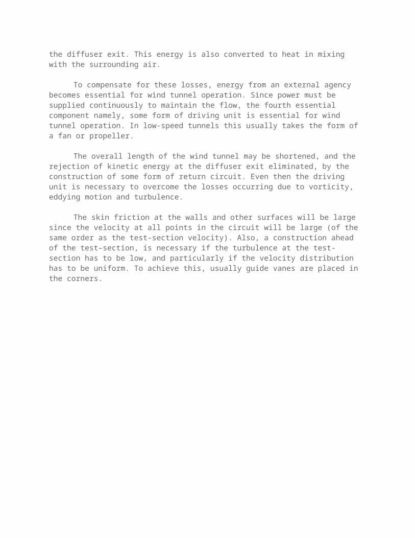
Layout of Open Circuit Wind TunnelsAll modern wind tunnels have four important components;
the Effuser
the Working or Test-section
the Diffuser
the Driving unit
The EffuserThis is a converging passage located upstream of the test-section. In this passage fluid gets
accelerated from rest (or from very low speed) at the upstream end of it to the required conditions at the test-section.In general, effuser contains honey-comb and wire gauze screens to reduce the turbulence and produce an uniform air stream at the exit. Effuser is usually referred to as contraction cone.
Test-sectionModel to be tested is placed here in the air-stream, leaving the downstream end of the effuser, and
the required measurements and observations are made. If the test-section is bounded by rigid walls, the tunnel is called a closed throat tunnel. If it is bounded by air at different velocity (usually at rest), the tunnel is called open jet tunnel. The test-section is also referred to as working-section.
DiffuserThe diffuser is used to re-convert the kinetic energy of the air-stream leaving the working-section
into pressure energy, as efficiently as possible. Essentially it is a passage in which the flow decelerates.
Driving UnitIf there were no losses, steady flow through the test-section could continue forever, once it is
established, without the supply of energy from an external agency. But in practice, losses do occur, and kinetic energyis being dissipated as heat in vorticity, eddying motion and turbulence. Moreover, as the expansion of the diffuser cannot continue to infinity, there is rejection of some amount of kinetic energy at the diffuser exit. This energy is also converted to heat in mixing with the surrounding air.
To compensate for these losses, energy from an external agency becomes essential for wind tunnel operation. Since power must be supplied continuously to maintain the flow, the fourth essential component namely, some form of driving unit is essential for wind tunnel operation. In low-speed tunnels this usually takes the form of a fan or propeller.
The overall length of the wind tunnel may be shortened, and the rejection of kinetic energy at the diffuser exit eliminated, by the construction of some form of return circuit. Even then the driving unit is necessary to overcome the losses occurring due to vorticity, eddying motion and turbulence.
The skin friction at the walls and other surfaces will be large since the velocity at all points in the circuit will be large (of the same order as the test-section velocity). Also, a construction ahead of the test–section, is necessary if the turbulence at the test-section has to be low, and particularly if the velocity distribution has to be uniform. To achieve this, usually guide vanes are placed in the corners.
Similarity ParametersGeometric similarityOne of the most important requirements of models is that there should be geometric similarity between the model and the prototype. By geometric similarity it is meant that ratios of corresponding dimensions in the model and the prototype should be the same.
Dynamic similarityEqually important as the geometric similarity is the requirement of dynamic similarity. In an actual flight, when the body moves through a medium, forces and moments are generated because of the viscosity of the medium and also due to its inertia, elasticity and gravity. The inertia, viscous, gravity and elastic forces generated on the body in flight can be expressed in terms of fundamental units. The important force ratios can be expressed as non dimensional numbers. For example,
Reynolds number (Re) = Inertia force/Viscous force Mach number = Inertia force/Elastic force Froude number = Inertia force/Gravity force Euler's number = Inertia force / Pressure force Weber Number = Inertia force / Surface tension force
The principle of dynamic similarity is that a scale model under same Reynolds number and Mach number will have forces and moments on it that can be scaled directly. The flow patterns on the full scale body and the model will be exactly similar.
It is not necessary and may not be possible that all the aforesaid non dimensional numbers be simulated simultaneously in any experiment. Depending on the flow regime or the type of experiments, certain non-dimensional parameters are important. For example, in a low speed flow regime, simulation of Reynolds number in the experiments is important to depict the conditions of actual flight. In a high speed flow, simulation of Mach number is significant. It may even be necessary and significant that more than one non dimensional parameter are simulated.
Definition / Application of Wind TunnelDefinition of a Wind Tunnel
A wind tunnel is a specially designed and protected space into which air is drawn, or blown, by mechanical means in order to achieve a specified speed and predetermined flow pattern at a given instant. The flow so achieved can be observed from outside the wind tunnel through transparent windows that enclose the test section and flow characteristics are measurable using specialized instruments. An object, such as a model, or some full-scale engineering structure, typically a vehicle, or part of it, can be immersed into the established flow, thereby disturbing it. The objectives of the immersion include being able to simulate,visualize, observe, and/or measure how the flow around the immersed object affects the immersed object.
Application of Wind TunnelThere are many uses of wind tunnels. They vary from ordinary to special: these include uses for
Subsonic, supersonic and hypersonic studies of flight; for propulsion and icing research; for the testing of models and full-scale structures, etc. Some common uses are presented below. Wind tunnels are used for the following:
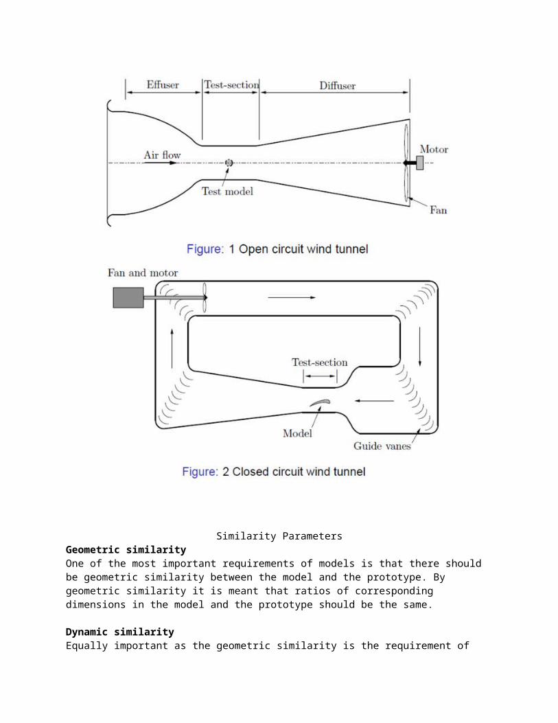
(i) To determine aerodynamic loads

Wind tunnels are used to determine aerodynamic loads on the immersed structure. The loads could be static forces and moments or dynamic forces and moments. Examples are forces and moments on airplane wings, airfoils, and tall buildings.
In our Aerodynamics lab we use load cells to calculate the drag and lift acting on the aerofoil, cylinder, and other models.
(ii) To study how to improve energy consumption by automobilesThey can also be used on automobiles to measure drag forces with a view to reducing the power required to move the vehicle on roads and highways.
(iii) To study flow patternsTo understand and visualize flow patterns near, and around, engineering structures. For example, how the wind affects flow around tall structures such as sky scrapers, factory chimneys, bridges, fences, groups of buildings, etc. How exhaust gases ejected by factories, laboratories, and hospitals get dispersed in their environments.
(iv) Other uses includeTo teach applied fluid mechanics, demonstrate how mathematical models compare to experimental results, demonstrate flow patterns, and learn and practice the use of instruments in measuring flow characteristics such as velocity, pressures, and torques.
Need of experiments
(i)Theory is incomplete and needs to be supplemented.
(ii) Information of fundamental nature needed in many areas.
Experimental information towards solving aerodynamic problems could be obtained in a number of ways. Flight tests, rocket flights, drop tests water tunnels, ballistic ranges and wind tunnels are some of the ways by which aerodynamic data can be generated. With the help of well performed experiments even information of fundamental nature could be derived.
Wind tunnelMajority of experimental data needed in aerodynamics is generated using wind tunnels. Wind Tunnel is a device for producing airflow relative to the body under test. Wind tunnels provide uniform flow conditions in their test section.
Unit I Classification of Wind TunnelsWind tunnels may be classified based on any of the following:(a) Speed, Mach noThey are classified as of low speed or high speed wind tunnels .In wind tunnel parlance, high speed wind tunnels are those operating at speeds where compressibility effects are important. They are also classified based on the Mach number of operation as subsonic, transonic, supersonic or hypersonic wind tunnels.
Range of the Mach number , M Name of flow , or conditionsM<1 SubsonicM=1, or near 1 Transonic1<M<3 Supersonic3<M<5 High supersonicM>5 HypersonicM>> 5 High Hypersonic
(b) Mode of operation (Pressure storage, in-draft or Pressure vacuum type.)(c) Kind of test section (T.S) - Open, Closed or Semi enclosed
Power Losses in a Wind TunnelThe total power loss in a wind tunnel may be split into the following components.
Losses in cylindrical parts.
Losses in guide vanes at the corner (in closed circuit tunnels).
Losses in diffuser.
Losses in contraction cone.
Losses in honey comb, screens etc.
Losses in test-section (jet losses in case of open jet).
Losses in exit in case of open circuit tunnel.
Special Purpose Wind Tunnels These are tunnels with layout totally different from that of low-speed and high-speed tunnels.
Some of the popular special purpose tunnels are: spinning tunnels, free-flight tunnels, stability
tunnels and low-density tunnels.
Define Horizontal Buoyancy ?
It is well known that the static-pressure-coefficient values obtained from tests of axisymmetric bodies in, for example, a large water tunnel indicate the existence of tunnel wall interference. This interference is due to blockage experienced by the body operating within the boundaries of the test section walls and to the skin friction on both the tunnel walls and the surface of the body, which, in turn, causes finite-thickness boundary layers to develop. These factors result in a decrease in static pressure along the test section, which leads to a spurious horizontal buoyancy on the body.
Unit II High Speed Wind TUnnelsHigh-Speed Wind Tunnels
High-speed tunnels are those with test-section speed more than 650 kmph.
The power to drive a low-speed wind tunnel varies as the cube of the test-section velocity. Although this rule is not valid for the highspeed regime, the implication of rapidly increasing power requirement with increasing test-section speed is true for high-speed tunnels also.
Because of the power requirements, high-speed wind tunnels are often of the intermittent type in which energy is stored in the form of pressure or vacuum or both and is allowed to drive the tunnel only a few seconds out of each pumping hour.
Even though the flow in the Mach number range from 0.5 to 5.0 is usually termed high-speed flow, the tunnels with test–section Mach number less than 0.9 are generally grouped and treated under subsonic wind tunnels.
Wind tunnels with Mach numbers from 1.5 to 5.0 are classified as supersonic tunnels
And those with Mach number more than 5 are termed hypersonic tunnels.
The wind tunnels in the Mach number range from 0.9 to 1.5 are called transonic tunnels.
High-speed tunnels are generally grouped into intermittent and continuous operation tunnels, based on the type of operation. The intermittent tunnels are further divided into blow down tunnels and induction tunnels, based on type of the operational procedure.
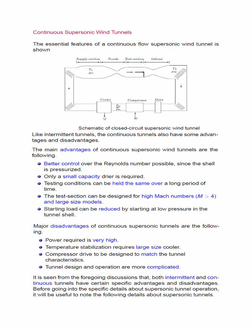
The intermittent blowdown and induction tunnels are normally used for Mach numbers from 0.5 to about 5.0, and the intermittent pressure-vacuum tunnels are normally used for higher Mach numbers. The continuous tunnel is used throughout the speed range. Both intermittent and continuous tunnels have their own advantages and disadvantages.

Hypersonic Wind Tunnel

UNITS and DIMENSIONS for few important terms
S.No QuantityUnit
generally adopted
DIMENSIONSMLT SYSTEM FLT SYSTEM
Geometric1. Length M L L2. Area M2 L2 L2
3. Volume M3 L3 L3
Kinematic5 Time Sec T T6 Velocity
(linear)M/sec LT-1 LT-1
7 Velocity (angular)
Rad / sec2 T-1 T-1
8 Acceleration (linear)
M/sec LT-2 LT-2
9 Acceleration (angular)
Rad /sec2 T2 T2
10 Discharge Cum /sec L3 T-1 L3T-1
12 Kinematic velocity
M/sec2 L2 T-1 L2T-1
Dynamic13 Mass Kg M FL-1 T2
14 Force Newton MLT-2 F15 Weight Newton MLT-2 F16 Mass density Kg /cum ML-3 FL-4T2
17 Specific weight Newton/cum ML-2T2 FL-3
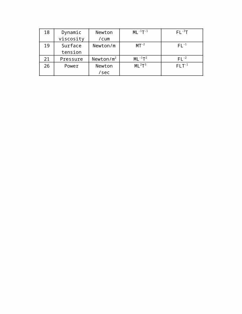
18 Dynamic viscosity
Newton /cum ML-1T-1 FL-3T
19 Surface tension Newton/m MT-2 FL-1
21 Pressure Newton/m2 ML-1T2 FL-2
26 Power Newton /sec ML2T3 FLT-1

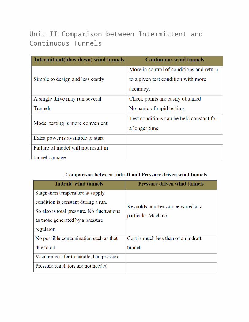
Unit II Comparison between Intermittent and Continuous Tunnels


![WTT NETWORK CONFIGURATION: METRO ROLLING STOCK...Figure 4 – Metro Rolling Stock [Passenger Vehicle] – Siemens Example Document Number: L1-CHE-MAN-016 Document Name: WTT Network](https://static.fdocuments.in/doc/165x107/614638c98f9ff81254202023/wtt-network-configuration-metro-rolling-stock-figure-4-a-metro-rolling-stock.jpg)