WTRP-Wireless Token Ring Protocolofdm.eecs.berkeley.edu/ergen/docs/main.pdf · WTRP-Wireless Token...
127
WTRP-Wireless Token Ring Protocol by Mustafa Ergen B. S. Middle East Technical University A thesis submitted in partial satisfaction of the Master of Science in Electrical Engineering and Computer Science in the GRADUATE DIVISION of the UNIVERSITY OF CALIFORNIA, BERKELEY Committee in charge: Professor Pravin Varaiya Professor Jean Walrand Spring 2002
Transcript of WTRP-Wireless Token Ring Protocolofdm.eecs.berkeley.edu/ergen/docs/main.pdf · WTRP-Wireless Token...

WTRP-Wireless Token Ring Protocolby
Mustafa Ergen
B. S. Middle East Technical University
A thesis submitted in partial satisfaction of the
Master of Science
in
Electrical Engineering and Computer Science
in the
GRADUATE DIVISION
of the
UNIVERSITY OF CALIFORNIA, BERKELEY
Committee in charge:
Professor Pravin Varaiya
Professor Jean Walrand
Spring 2002

Abstract
WTRP (Wireless Token Ring Protocol) is a medium access control (MAC) protocol for wireless
networks. The MAC protocol through which mobile stations can share a common broadcast channel
is essential in wireless networks. In a IEEE 802.11 network, the contention among stations is not
homogeneous due to the existence of hidden terminals, partially connected network topology, and
random access. Consequently, quality of service (QoS) is not provided. WTRP supports guaranteed
QoS in terms of bounded latency and reserved bandwidth which are crucial real time constraints of
the applications. WTRP is efficient in the sense that it reduces the number of retransmissions due
to collisions. It is fair in the sense that each station use the channel for equal amount of time. The
stations take turn to transmit and are forced to give up the right to transmit after transmitting for
a specified amount of time. It is a distributed protocol that supports many topologies since not all
stations need to be connected to each other or to a central station. WTRP is robust against single
node failure. WTRP recovers gracefully from multiple simultaneous faults. WTRP has applications
to inter-access point coordination in ITS DSRC, safety-critical vehicle-to-vehicle networking, home
networking and provides extensions to sensor networks and Mobile IP.
i
Contents
1 Overview 1
1.1 Introduction . . . . . . . . . . . . . . . . . . . . . . . . . . . . . . . . . . . . . . 1
1.2 Applications . . . . . . . . . . . . . . . . . . . . . . . . . . . . . . . . . . . . . . 3
1.2.1 Unmanned Vehicles . . . . . . . . . . . . . . . . . . . . . . . . . . . . . 3
1.2.2 Home Networking . . . . . . . . . . . . . . . . . . . . . . . . . . . . . . 4
1.3 History of WTRP . . . . . . . . . . . . . . . . . . . . . . . . . . . . . . . . . . . 4
1.4 Summary . . . . . . . . . . . . . . . . . . . . . . . . . . . . . . . . . . . . . . . 5
2 Network Architecture 7
2.1 Introduction . . . . . . . . . . . . . . . . . . . . . . . . . . . . . . . . . . . . . . 7
2.2 Overall System Architecture . . . . . . . . . . . . . . . . . . . . . . . . . . . . . 7
2.2.1 Medium Access Control . . . . . . . . . . . . . . . . . . . . . . . . . . . 8
2.2.2 Channel Allocator . . . . . . . . . . . . . . . . . . . . . . . . . . . . . . 9
2.2.3 Mobility Manager . . . . . . . . . . . . . . . . . . . . . . . . . . . . . . 10
2.2.4 Admission Control . . . . . . . . . . . . . . . . . . . . . . . . . . . . . . 10
2.2.5 Policer . . . . . . . . . . . . . . . . . . . . . . . . . . . . . . . . . . . . 11
2.2.6 Management Information Base (MIB) . . . . . . . . . . . . . . . . . . . . 11
2.3 Summary . . . . . . . . . . . . . . . . . . . . . . . . . . . . . . . . . . . . . . . 11
i
3 Protocol Overview 12
3.1 Definitions . . . . . . . . . . . . . . . . . . . . . . . . . . . . . . . . . . . . . . . 12
3.2 Observations . . . . . . . . . . . . . . . . . . . . . . . . . . . . . . . . . . . . . 13
3.3 Description . . . . . . . . . . . . . . . . . . . . . . . . . . . . . . . . . . . . . . 13
3.4 Summary . . . . . . . . . . . . . . . . . . . . . . . . . . . . . . . . . . . . . . . 19
4 Specification 20
4.1 Introduction . . . . . . . . . . . . . . . . . . . . . . . . . . . . . . . . . . . . . . 20
4.2 MIB Parameters . . . . . . . . . . . . . . . . . . . . . . . . . . . . . . . . . . . . 20
4.3 Timers . . . . . . . . . . . . . . . . . . . . . . . . . . . . . . . . . . . . . . . . . 21
4.3.1 Definitions . . . . . . . . . . . . . . . . . . . . . . . . . . . . . . . . . . 21
4.3.2 Timer Types . . . . . . . . . . . . . . . . . . . . . . . . . . . . . . . . . 22
4.3.3 Timer Handlers . . . . . . . . . . . . . . . . . . . . . . . . . . . . . . . . 23
4.4 Frame Formats . . . . . . . . . . . . . . . . . . . . . . . . . . . . . . . . . . . . 24
4.4.1 Frame Control Field . . . . . . . . . . . . . . . . . . . . . . . . . . . . . 24
4.4.2 Sequence Control Fields . . . . . . . . . . . . . . . . . . . . . . . . . . . 25
4.4.3 Address Fields . . . . . . . . . . . . . . . . . . . . . . . . . . . . . . . . 26
4.4.4 Admission Control Field . . . . . . . . . . . . . . . . . . . . . . . . . . . 26
4.4.5 Queues . . . . . . . . . . . . . . . . . . . . . . . . . . . . . . . . . . . . 26
4.4.6 Invalid Frame . . . . . . . . . . . . . . . . . . . . . . . . . . . . . . . . . 26
4.4.7 Frame Types . . . . . . . . . . . . . . . . . . . . . . . . . . . . . . . . . 27
4.5 Summary . . . . . . . . . . . . . . . . . . . . . . . . . . . . . . . . . . . . . . . 29
5 Finite State Machine 30
5.1 Introduction . . . . . . . . . . . . . . . . . . . . . . . . . . . . . . . . . . . . . . 30
ii
5.2 States . . . . . . . . . . . . . . . . . . . . . . . . . . . . . . . . . . . . . . . . . 32
5.2.1 Beginning State. . . . . . . . . . . . . . . . . . . . . . . . . . . . . . . . 32
5.2.2 Floating State. . . . . . . . . . . . . . . . . . . . . . . . . . . . . . . . . 32
5.2.3 Offline State. . . . . . . . . . . . . . . . . . . . . . . . . . . . . . . . . . 33
5.2.4 Joining State . . . . . . . . . . . . . . . . . . . . . . . . . . . . . . . . . 33
5.2.5 Soliciting State . . . . . . . . . . . . . . . . . . . . . . . . . . . . . . . . 34
5.2.6 Idle State . . . . . . . . . . . . . . . . . . . . . . . . . . . . . . . . . . . 35
5.2.7 Monitoring State . . . . . . . . . . . . . . . . . . . . . . . . . . . . . . . 36
5.2.8 Have Token State. . . . . . . . . . . . . . . . . . . . . . . . . . . . . . . 36
5.3 Operating Types . . . . . . . . . . . . . . . . . . . . . . . . . . . . . . . . . . . . 37
5.3.1 Normal Operating Flow . . . . . . . . . . . . . . . . . . . . . . . . . . . 37
5.3.2 Saturation Operating Flow . . . . . . . . . . . . . . . . . . . . . . . . . . 38
5.4 Summary . . . . . . . . . . . . . . . . . . . . . . . . . . . . . . . . . . . . . . . 38
6 Implementation Overview 39
6.1 Introduction . . . . . . . . . . . . . . . . . . . . . . . . . . . . . . . . . . . . . . 39
6.2 State Transitions . . . . . . . . . . . . . . . . . . . . . . . . . . . . . . . . . . . 40
6.3 Data Flow . . . . . . . . . . . . . . . . . . . . . . . . . . . . . . . . . . . . . . . 41
6.4 Data Structures . . . . . . . . . . . . . . . . . . . . . . . . . . . . . . . . . . . . 41
6.4.1 StationStructure . . . . . . . . . . . . . . . . . . . . . . . . . . . . . . . 41
6.4.2 DeviceStructure . . . . . . . . . . . . . . . . . . . . . . . . . . . . . . . 43
6.5 Summary . . . . . . . . . . . . . . . . . . . . . . . . . . . . . . . . . . . . . . . 43
7 Wireless Token Ring Simulator 45
7.1 Introduction . . . . . . . . . . . . . . . . . . . . . . . . . . . . . . . . . . . . . . 45
iii

7.2 Architecture . . . . . . . . . . . . . . . . . . . . . . . . . . . . . . . . . . . . . . 46
7.2.1 Animator . . . . . . . . . . . . . . . . . . . . . . . . . . . . . . . . . . . 47
7.2.2 Visual Tracer & Analyzer . . . . . . . . . . . . . . . . . . . . . . . . . . 49
7.2.3 Simulator Engine . . . . . . . . . . . . . . . . . . . . . . . . . . . . . . . 50
7.2.4 Simulator Run . . . . . . . . . . . . . . . . . . . . . . . . . . . . . . . . 52
7.3 Summary . . . . . . . . . . . . . . . . . . . . . . . . . . . . . . . . . . . . . . . 54
8 User Space Implementation 55
8.1 Introduction . . . . . . . . . . . . . . . . . . . . . . . . . . . . . . . . . . . . . . 55
8.2 Implementation . . . . . . . . . . . . . . . . . . . . . . . . . . . . . . . . . . . . 55
8.2.1 Initialization . . . . . . . . . . . . . . . . . . . . . . . . . . . . . . . . . 55
8.2.2 System Call (IOCTL) . . . . . . . . . . . . . . . . . . . . . . . . . . . . . 57
8.2.3 Application Interface (WoW API) . . . . . . . . . . . . . . . . . . . . . . 57
8.2.4 User Space Engine . . . . . . . . . . . . . . . . . . . . . . . . . . . . . . 58
8.2.5 Transmission . . . . . . . . . . . . . . . . . . . . . . . . . . . . . . . . . 59
8.2.6 Reception . . . . . . . . . . . . . . . . . . . . . . . . . . . . . . . . . . . 59
8.3 Summary . . . . . . . . . . . . . . . . . . . . . . . . . . . . . . . . . . . . . . . 60
9 Kernel Implementation 61
9.1 Introduction . . . . . . . . . . . . . . . . . . . . . . . . . . . . . . . . . . . . . . 61
9.2 Kernel Modules . . . . . . . . . . . . . . . . . . . . . . . . . . . . . . . . . . . . 64
9.3 Real Time Processes in Linux . . . . . . . . . . . . . . . . . . . . . . . . . . . . 64
9.4 Old tale of WaveLAN . . . . . . . . . . . . . . . . . . . . . . . . . . . . . . . . . 64
9.4.1 Initialization . . . . . . . . . . . . . . . . . . . . . . . . . . . . . . . . . 66
9.4.2 Transmission . . . . . . . . . . . . . . . . . . . . . . . . . . . . . . . . . 67
iv
9.4.3 Reception . . . . . . . . . . . . . . . . . . . . . . . . . . . . . . . . . . . 68
9.5 Installing WTRP to Kernel . . . . . . . . . . . . . . . . . . . . . . . . . . . . . . 69
9.5.1 Initialization . . . . . . . . . . . . . . . . . . . . . . . . . . . . . . . . . 69
9.5.2 Loading the Protocol . . . . . . . . . . . . . . . . . . . . . . . . . . . . . 70
9.5.3 Initializing the Protocol . . . . . . . . . . . . . . . . . . . . . . . . . . . 71
9.5.4 Protocol Hooks . . . . . . . . . . . . . . . . . . . . . . . . . . . . . . . . 71
9.5.5 Headers on Data Packets . . . . . . . . . . . . . . . . . . . . . . . . . . . 71
9.5.6 Transmission . . . . . . . . . . . . . . . . . . . . . . . . . . . . . . . . . 72
9.5.7 Reception . . . . . . . . . . . . . . . . . . . . . . . . . . . . . . . . . . . 73
9.5.8 Overhead . . . . . . . . . . . . . . . . . . . . . . . . . . . . . . . . . . . 73
9.5.9 User Interface . . . . . . . . . . . . . . . . . . . . . . . . . . . . . . . . . 74
9.6 Summary . . . . . . . . . . . . . . . . . . . . . . . . . . . . . . . . . . . . . . . 74
10 Analysis 76
10.1 Proof of Stability . . . . . . . . . . . . . . . . . . . . . . . . . . . . . . . . . . . 76
10.1.1 Introduction . . . . . . . . . . . . . . . . . . . . . . . . . . . . . . . . . . 76
10.1.2 Model . . . . . . . . . . . . . . . . . . . . . . . . . . . . . . . . . . . . . 77
10.1.3 Graph . . . . . . . . . . . . . . . . . . . . . . . . . . . . . . . . . . . . . 77
10.1.4 Network . . . . . . . . . . . . . . . . . . . . . . . . . . . . . . . . . . . . 80
10.1.5 Proof . . . . . . . . . . . . . . . . . . . . . . . . . . . . . . . . . . . . . 80
10.1.6 Conclusion . . . . . . . . . . . . . . . . . . . . . . . . . . . . . . . . . . 88
10.2 Saturation Throughput Analysis . . . . . . . . . . . . . . . . . . . . . . . . . . . 89
10.2.1 Introduction . . . . . . . . . . . . . . . . . . . . . . . . . . . . . . . . . . 89
10.2.2 Model . . . . . . . . . . . . . . . . . . . . . . . . . . . . . . . . . . . . . 89
10.2.3 Throughput . . . . . . . . . . . . . . . . . . . . . . . . . . . . . . . . . . 92
v

10.2.4 Conclusion . . . . . . . . . . . . . . . . . . . . . . . . . . . . . . . . . . 97
10.3 Summary . . . . . . . . . . . . . . . . . . . . . . . . . . . . . . . . . . . . . . . 97
11 Performance Analysis 98
11.1 Performance Analysis . . . . . . . . . . . . . . . . . . . . . . . . . . . . . . . . . 98
11.1.1 Scenario . . . . . . . . . . . . . . . . . . . . . . . . . . . . . . . . . . . . 98
11.1.2 Optimum Operating Frequency . . . . . . . . . . . . . . . . . . . . . . . 99
11.1.3 Bound on Latency . . . . . . . . . . . . . . . . . . . . . . . . . . . . . . 102
11.1.4 Robustness and Responsiveness . . . . . . . . . . . . . . . . . . . . . . . 104
11.1.5 Fairness . . . . . . . . . . . . . . . . . . . . . . . . . . . . . . . . . . . . 105
11.1.6 Network Size . . . . . . . . . . . . . . . . . . . . . . . . . . . . . . . . . 106
11.2 Summary . . . . . . . . . . . . . . . . . . . . . . . . . . . . . . . . . . . . . . . 108
12 System Extensions 110
12.1 Introduction . . . . . . . . . . . . . . . . . . . . . . . . . . . . . . . . . . . . . . 110
12.2 Hybrid Schemes . . . . . . . . . . . . . . . . . . . . . . . . . . . . . . . . . . . . 110
12.3 Token Chain . . . . . . . . . . . . . . . . . . . . . . . . . . . . . . . . . . . . . . 111
12.4 Sensor Networks . . . . . . . . . . . . . . . . . . . . . . . . . . . . . . . . . . . 111
12.5 Data Forwarding . . . . . . . . . . . . . . . . . . . . . . . . . . . . . . . . . . . 113
12.6 Extension to Mobile IP . . . . . . . . . . . . . . . . . . . . . . . . . . . . . . . . 113
12.7 Multimedia . . . . . . . . . . . . . . . . . . . . . . . . . . . . . . . . . . . . . . 114
12.8 Summary . . . . . . . . . . . . . . . . . . . . . . . . . . . . . . . . . . . . . . . 114
13 Conclusion 115
vi

Chapter 1
Overview
1.1 Introduction
WTRP (Wireless Token Ring Protocol) is a medium-access-control (MAC) protocol for applications
running on wireless ad-hoc networks that provide quality of service. In ad hoc networks, participat-
ing stations can join or leave at any moment in time. This implies a dynamic topology. The MAC
protocol through which mobile stations can share a common broadcast channel is essential in an
ad-hoc network. Due to the existence of hidden terminals and partially connected network topol-
ogy, contention among stations in an ad-hoc network is not homogeneous. Some stations can suffer
severe throughput degradation in access to the shared channel when load of the channel is high,
which also results in unbounded medium access time for the stations. This challenge is addressed
as quality of service (QoS) in a communication network.
In networks, QoS efforts have focused on network layer queuing and routing techniques [5],[6].
In an unreliable medium such as wireless, providing QoS at the network layer using queuing and
routing techniques is not sufficient. QoS must also be addressed at the data-link layer. The IEEE
802.11 [7] in PCF (Point Coordination Function) mode, the HiperLAN [18], and Bluetooth [19]
1

achieve bounded latency by having a central station poll the slave stations. Most academic research
has focused on this centralized approach [9],[8]. The centralized approach is suitable for networks
where only the last hop is wireless. In the centralized approach, the network is managed centrally
from a central station.
The Wireless Token Ring Protocol (WTRP) discussed in this paper is a distributed medium
access control protocol for ad-hoc networks. Its advantages are robustness against single node
failure, and support for flexible topologies, in which nodes can be partially connected and not all
nodes need to have a connection with a master. Current wireless distributed MAC protocols such
as the IEEE 802.11 (Distributed Coordination Function (DCF) mode) and the ETSI HIPERLAN do
not provide QoS guarantees that are required by some applications. In particular, medium is not
shared fairly among stations and medium-access time can be arbitrarily long [12], [13].
As in the IEEE 802.4 [4] standards, WTRP is designed to recover from multiple simultane-
ous failures. One of the biggest challenges that the WTRP overcomes is partial connectivity. To
overcome the problem of partial connectivity, management, special tokens, additional fields in the
tokens, and new timers are added to WTRP. When a node joins a ring, it is required that the join-
ing node be connected to the prospective predecessor and the successor. The joining node obtains
this information by looking up its connectivity table. When a node leaves a ring, the predecessor
of the leaving node finds the next available node to close the ring by looking up its connectivity
table. Partial connectivity also affects the multiple token resolution protocol (deleting all multiple
tokens but one). In a partially connected network, simply dropping the token whenever a station
hears another transmission is not sufficient. To delete tokens that a station is unable to hear, we
have designed a unique priority assignment scheme for tokens. Stations only accept a token that has
greater priority than the token the station last accepted. The WTRP also has algorithms for keeping
each ring address unique, to enable the operation of multiple rings in proximity.
2

WTRP has other desirable properties. It achieves high medium utilization since the collision
probability is reduced by scheduling the transmission with token reception. WTRP distributes
throughput in a flexible and fair manner among stations because each station in the ring takes a
turn to transmit and forced to give up the right to transmit after a fixed time that results in bounds
on medium-access time.
1.2 Applications
The wireless ad hoc network has many applications: Military, rescue missions, national security,
commercial use, education, sensor networks, in which there is a need for rapid establishment of a
communication infrastructure. Usefulness of the WTRP protocol is applicable in all these areas and
some of applications are described here and in Chapter 12.1.
1.2.1 Unmanned Vehicles
One of the trends in transportation studies is the application of inter-vehicles communication. WTRP
is to be deployed initially for University of California at Berkeley PATH Advanced Vehicle Safety
Systems Program [10], the CALTRANS-PATH Demonstration 2002, and the Berkeley Aerobot
project [15]. These applications impose stringent bandwidth, latency, and speed of failure recovery
requirements on the medium access protocol. The platoon mode of the automated highway project
involves up to 20 nodes in each platoon, and requires that information (approximately 100 bytes per
vehicle for speed, acceleration, and coordination maneuvers) be transmitted periodically. WTRP
meets the application requirements in terms of bounded delay and share of bandwidth to all stations
in the network and fast failure recovery if there is a failure in a station.
3
1.2.2 Home Networking
Home networks link1 many different electronic devices in a household through a connected local
area network (LAN). Home networking allows all users in the household to access the Internet
and applications at the same time. In addition data, audio, and video files can be swapped, and
peripherals such as printers and scanners can be shared. There is no longer the need to have more
than one Internet access point, printer, scanner, or in many cases, software packages.
In the future, the broadband “pipe” coming into a home will carry more than the Internet; it
will also carry new telephone and entertainment services in the form of streaming video and audio
and interactive networked games. Consequently, more devices that have real time constraints are
expected to compete for the frequency band of wireless LAN as both number of users and type of
wireless LAN devices increase in number. One observes that total aggregate throughput diminishes
dramatically in IEEE 802.11 (DCF mode) with increase in number of concurrent transmissions due
to collisions as shown in [2]. Apart from WTRP, other protocols take the centralized approach in
home networking. Distributed property of WTRP provides partial connectivity in which all nodes
need not to be connected with the access point. Partial connectivity, reduce transmission power and
with packet forwarding of WTRP, connection is guaranteed for a node away from the range of the
access point.
1.3 History of WTRP
WTRP was first designed for Automated highway project [10]. The first version was designed by
Duke Lee in 1998. The second version was implemented with Teja software [23], released by Duke
1According to the Yankee group [27], 29 percent of U.S. households have multiple PCs. Many of these householdsalso have high-speed (Broadband) Internet access (either cable modem or DSL). According to a recent report by ARSof La Jolla [28], there are now 5.1 million cable modem subscribers and 3.3 million DSL subscribers today. The totalnumber is expected is grow to 28 million by 2004.
4
Lee, Roberto Attias , Dr.Stavros Tripakis, Dr.Anuj Puri, Dr.Raja Sengupta, and Prof.Pravin Varaiya
in 2000 and reported in [2]. The last version is implemented in Linux Operating System with three
deliverables by Duke Lee, Ruchira Datta, Jeff Ko, Dr.Anuj Puri, Dr.Raja Sengupta, Prof.Pravin
Varaiya and by the author in August 2001 and published online2 as an open source software.
In this version, compared to the second version, we simplified the Finite State Machine of the
protocol. We introduced a distributed admission control procedure. Unlike the second version in
which the module is implemented in application layer and hooked to the kernel, a kernel implemen-
tation is built as a Linux link layer module.
Besides the kernel implementation, we built a user-space implementation that works solely in
the application layer as a platform-independent scheduler and a simulator that enables testing the
protocol in a wireless environment.
1.4 Summary
In wireless medium, network layer modifications are insufficient to provide quality of service (QoS).
QoS must also be addressed in link layer. Wireless Token Ring Protocol is a medium access pro-
tocol that provides QoS in terms of bounded latency and reserved bandwidth. WTRP overcomes
the challenges introduced by ad hoc wireless medium through procedures for joining, leaving and
failure recovery.
Applications of Intelligent Transportation Systems require QoS in terms of delay-bounds or fair
share of the spectrum. This quality of service guarantee is critical in mesh stability of the formation
of the vehicles. The communication of the speed and the velocity of the lead vehicle to all other
vehicles in the formation had been shown to be sufficient for mesh stability of the system. In the
future in a home, more devices are expected to compete for the frequency band of Wireless LAN.
2http://wow.eecs.berkeley.edu/WTRP
5

They require QoS in order to reduce collision and create connectivity.
WTRP has been developed by Berkeley Web over Wireless Group [1] since 1998 and the last
version was distributed in 2001.
6

Chapter 2
Network Architecture
2.1 Introduction
Inspired by the IEEE 802.4 [4] standards, WTRP builds a logical ring that defines a transmission
sequence among the nodes in the ring. It also provides a distributed way to add and delete stations
from the ring. When adapting a MAC protocol designed for wireline networks to the wireless ad hoc
case, additional challenges are encountered in the wireless environment. The stations in the network
are organized into multiple rings that can exists in proximity. Stations may not be fully connected
that means not all nodes in the ring are directly connected. Radio range can be asymmetrical. In
this chapter, we describe the design of WTRP to cope with these issues and outline the functions of
each module, and discuss the context in which these modules are designed.
2.2 Overall System Architecture
To put WTRP into a context in terms its placement in the communication system, we describe
the overall system architecture in Figure 2.1. In addition to the communication stack including
the Datalink Layer where WTRP will be located, we need Mobility Manager, Channel Allocator,
7

Transmission Entity
Physical Medium
MIB
Mobility Manager
Admission Control
Channel Allocator
Physical Layer
Network Layer
MIB
Mobility Manager
Channel Allocator
Admission Control
Network Layer
Physical Layer
Datalink LayerDatalink Layer
Figure 2.1: System Architecture
Management Information Base (MIB), and Admission Control Manager. We assume that multiple
channels are available, and that different rings are on different channels. Different rings are assigned
to different channels by a channel allocator (Section 2.2.2).
2.2.1 Medium Access Control
Medium Access Control (MAC) enables multiple nodes to transmit on the same medium. This is
where WTRP is located. The main function of MAC is to control the timing of the transmissions by
different nodes to increase the chance of successful transmission.
In our architecture, the MAC layer performs ring management and timing of the transmissions.
The ring management involves:
1. Ensuring that each ring has a unique ring address.
2. Ensuring that one and only one token exists in a ring.
3. Ensuring that the rings are proper.
4. Managing the joining and the leaving operations.
We will describe the operations of the MAC layer in Section 3 and Section 4.
8

2.2.2 Channel Allocator
In a general sense, the channel allocator chooses the channel on which the station should trans-
mit. If a large number of token rings exist in proximity, their efficiency can be increased by achiev-
ing spatial reuse through sensible channel allocation. The idea of spatial reuse is a core idea of
wireless cellular telephony. The same channel (or a set of channels) can be reused in region A and
B, if the two regions are separated by sufficient distance measured in terms of the signal to inter-
ference ratio. One way to increase spatial reuse is to reduce the cell size. Reducing the cell size
(by reducing the transmission power) increases the capacity and decrease equipment costs. How-
ever, dividing the nodes into multiple rings will reduce the number of nodes in a ring, and thereby
increase routing overhead between rings.
Finding the globally optimal solution for channel allocation, an allocation that maximizes the
capacity of the network, is a challenging problem in any large deployment of many mobile nodes.
First, collecting and maintaining channel allocation information can be difficult and burdensome.
This is because the collection and maintenance of information may involve frequent packet trans-
missions. Second, the optimal allocation computation is complex. The complexity of the problem
is greater than that of allocating channels to already divided regions, allocating with the restriction
that no adjacent regions can have the same channel. Moreover, in our applications, the network
capacity must be maintained without violating the latency and the bandwidth requirements of each
node.
A much more scalable solution could be a distributed one. And this is the method that is being
considered for our design. In our implementation, the channel allocator is local to each station,
and the channel allocator can access the network topology information through the MIB. Each
node decides on which channel to join in a distributed manner using the information collected from
9
the token structure, which contains the number of nodes (NoN) in the ring. If NoN reaches the
maximum value, this is an indication for the nodes out of the ring to shift to the next channel and
search for another ring.
2.2.3 Mobility Manager
The Mobility Manager decides when a station should join or leave the ring. The problem that the
Mobility Manager has to solve is similar to the mobile hand-off problem. When a mobile node
is drifting away from a ring and into the vicinity of another ring, at some threshold the Mobility
Manager decides to move to the next ring. The level of connection of a node to a ring can be found
from the connectivity table described in Section 3.
2.2.4 Admission Control
The Admission Control Manager limits the number of stations that can transmit on the medium.
This is to ensure that a level of quality of service in terms of bounded latency and reserved band-
width is maintained for stations already granted permission to transmit on the medium. There is
an Admission Control Manager in each ring. The Admission Control Manager may move with
the token but does not have to move every time the token moves. The Admission Control Man-
ager periodically solicits other stations to join if there are “resources” available in the ring. The
“resource” of the token ring can be defined in the following way. The MAXMTRT is the min-
imum of the maximum latency that each station in the ring can tolerate. RESVMTRT is the
sum of token holding time (THT) of each station. MAXNoN is the maximum number of node
(NoN) that is allowed in the ring. The Admission Control Manager has to ensure the inequality:
RESV MTRT < MAX MTRT andNoN < MAX NoN . Only if these inequalities are sat-
isfied, may the Admission Control Manager solicit another station to join. During the solicitation,
10
the Admission Control Manager also advertises the available resources. Only stations that require
less resource than available in the ring may join.
2.2.5 Policer
The policer monitors the traffic generated by the application. It throttles the application when more
traffic than reserved is produced. In the WTRP, because the token holding timer polices the traffic
generated by a station, no special policer module is necessary.
2.2.6 Management Information Base (MIB)
The Management Information Base holds all the information that each management module needs
to manage the MAC module. Majority of this information is collected by the MAC module and
stored there. However, some of the information may need to be communicated. This is gathered
and refreshed by the SNMP agent. Details on this are still being investigated.
2.3 Summary
In order to manage the wireless medium, WTRP operates in conjunction with several modules.
Medium Access Control is where WTRP is located, Channel Allocator deals with channel assign-
ment of rings in order to avoid interference, Mobility Manager performs hand over in case of move-
ment. Admission Control manages the ring size and invites if there is room. Policer monitors the
traffic and perform congestion control, Management Information Base is the place where the ring
parameters is stored.
11

Chapter 3
Protocol Overview
3.1 Definitions
1. WTRP refers to Wireless Token Ring Protocol, the topic of this report.
2. The term “frame” refers to the sequence of bits that is passed to the physical layer for one
packet. A “frame” does not include the preamble, the start delimiter, the CRC check, and the
end delimiter.
3. The terms “station” and “node” are used interchangeably to describe the communication en-
tities on the shared medium.
4. The predecessor and the successor of station X describe the station that X receives the token
from and the station that the X passes the token to, respectively.
5. “Incorrect state” means that a node’s view of the topology is wrong. For example node X
may believe that node Y is its predecessor, but node Y does not.
6. “Stable environment” refers to a state in which the topology of the network is fixed and there
are no transmission errors.
12

7. “Proper ring” refers to a ring where the successor and predecessor fields of a node are correct.
It is more precisely defined in Section 10.1.
8. Capacity of the network refers to the total bandwidth.
9. The Channel Allocator, Mobility Manager, and Admission Control Manager introduced in
Section 2.2 are referred to as “management modules”.
10. THT refers to the Token Holding Time, i.e., the amount of time that a station can hold the
token for transmission of data.
11. NoN refers to the Number of Nodes in the ring.
3.2 Observations
1. Not all stations need to be involved in token passing. Only those stations which desire to
initiate data transmission need to be involved.
2. Any station may detect multiple tokens and lost tokens. There are no special “monitor” station
required to perform token recovery functions.
3. Due to errors, stations may not have a consistent view of the ring.
3.3 Description
In WTRP, the successor and the predecessor fields of each node in the ring define the ring and the
transmission order. A station receives the token from its predecessor, transmits data, and passes the
token to its successor. Here is an illustration of the token frame.
13

F
B
C
A
D
E
Seq=1
Seq=5
Seq=4
Seq=3
Seq=2
G H
Addr=E
Addr=C
Addr=B
Unknown
Unknown
Addr=H
Addr=G
Connectivity Table of D
My Table Other Table
Transmission Range of D
L
Figure 3.1: Connectivity Table
FC RA DA SA NoN GenSeq Seq
1 6 6 6 2 4 4 bytes
FC stands for Frame Control and it identifies the type of packet, such as Token, Solicit Suc-
cessor, Set Predecessor, etc. In addition, the source address (SA), destination addresses (DA), ring
address (RA), sequence number (Seq) and generation sequence (GenSeq) number are included in
the token frame. The ring address refers to the ring to which the token belongs. The sequence
number is initialized to zero and incremented by every station that passes the token. The generation
sequence number is initialized to zero and incremented at every rotation of the token by the creator
of the token. The number of nodes (NoN) in the ring is represented in the token frame and calculated
by taking the difference of sequence numbers in one rotation.
The Connectivity manager resident on each node tracks transmissions from its own ring and
those from other nearby rings. By monitoring the sequence number of the transmitted tokens, the
Connectivity Manager builds an ordered local list of stations in its own ring and an unordered global
list of stations outside its ring (See Figure 3.1). In Figure 3.1, station D monitors the successive
14

token transmission from E to F before the token comes back to D. At time 0, D transmits the token
with sequence number 0, at time 1, E transmits the token with the sequence number 1, and so on. D
will not hear the transmission from F and A, but when it hears transmission from B, D will notice
that the sequence number has been increased by 3 instead of 1. This indicates to E that there were
two stations that it could not hear between E and B.
The Ring Owner is the station that has the same MAC address as the ring address. A station can
claim to be the ring owner by changing the ring address of the token that is being passed around.
Stations rely on implicit acknowledgements to monitor the success of their token transmissions.
An implicit acknowledgement is any packet heard after token transmission that has the same ring
address as the station. Another acceptable implicit acknowledgement is any transmission from a
successive node regardless of the ring address in the transmission. A successive node is a station
that was in the ring during the last token rotation. In other words, the successing stations are those
present in the local connectivity table.
Each station resets itsidle timerwhenever it receives an implicit acknowledgement. If the token
is lost in the ring, then no implicit acknowledgement will be heard in the ring, and theidle timer
will expire. When theidle timer expires, the station generates a new token, thereby becoming the
owner of the ring.
To resolve multiple tokens (to delete all tokens but one), the concept of priority is used. The
generation sequence number and the ring address define the priority of a token. A token with a
higher generation sequence number has higher priority. When the generation sequence numbers of
tokens are the same, ring addresses of each token are used to break the tie. The priority of a station
is the priority of the token that the station accepted or generated. When a station receives a token
with a lower priority than itself, it deletes the token and notifies its predecessor without accepting
the token. With this scheme, it can be shown that the protocol deletes all multiple tokens in a single
15

B
C
A
Br.
S A S B
S B
Station A
Solicit_Successor Set_Predecessor
NS
S C
S A
S B
S B
S C
Station B
Set_Successor Set_Predecessor
Br. S C
NS
S C
Station C
Time
Figure 3.2: Joining
token rotation provided no more tokens are being generated (See Section 10.1).
The ring recovery mechanism is invoked when the monitoring node decides that its successor
is unreachable. In this case, the station tries to recover from the failure by forming the ring again.
The strategy taken by the WTRP is to try to reform the ring by excluding as few as possible. Using
the Connectivity Manager, the monitoring station is able to quickly find the next connected node
in the transmission order. The monitoring station then sends thesetpredecessortoken to the next
connected node to close the ring.
WTRP allows nodes to join a ring dynamically, one at a time, if the token rotation time (sum
of token holding times per node, plus overhead such as token transmission times) would not grow
unacceptably with the addition of the new node. As illustrated in Figure 3.2, suppose station B wants
to join the ring. Let us also say that the admission control manager on station A broadcasts (Br.)
other nodes to join the ring by sending out asolicit successorthat includes successor(C) of A. The
Admission Control Manager waits for the duration of the response window for interested nodes to
respond. The response window represents the window of opportunity for a new node to join the
ring. The response window is divided into slots of the duration of theset successortransmission
time. When a node, such as B that wants to join the ring, hears asolicit successortoken, it picks a
16
B
C
A
S C
Station C
S A
S C Station B
Set_Successor
NS
S A S C
S C Station A
Set_Predecessor
Time
Figure 3.3: Exiting
A
C
D
B
E
F
L
N
O
M
P
F
H
J
K
I
B
G
S
V
Y
T
Z
R
Ring A Channel 2
Ring H Channel 1
Ring N Channel 3
Ring S Channel 1
Figure 3.4: Multiple Rings
random slot and transmits aset successortoken. When the response window passes, the host node,
A can decide among the slot winners. Suppose that B wins the contention, then the host node passes
the setpredecessor token to B, and B sends thesetpredecessorto node C, the successor of the host
node A. The joining process concludes.
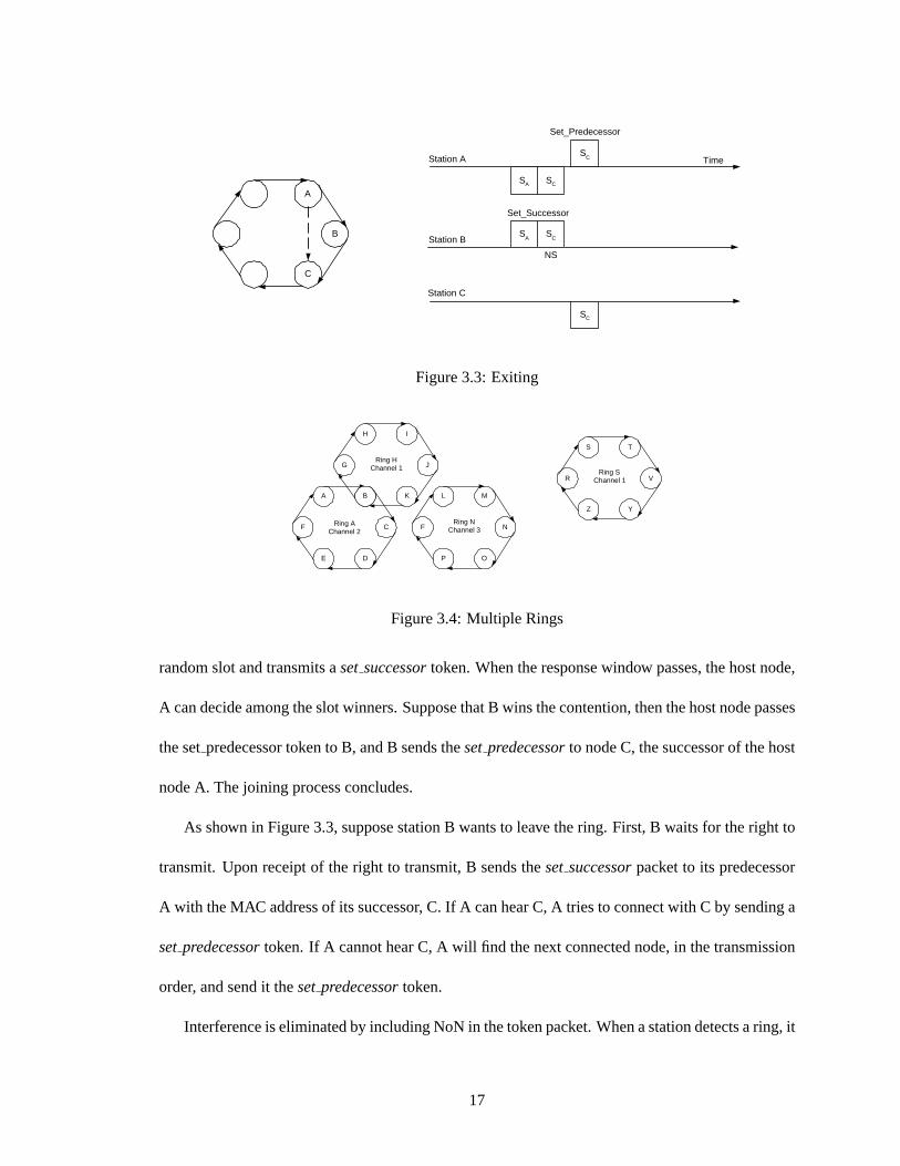
As shown in Figure 3.3, suppose station B wants to leave the ring. First, B waits for the right to
transmit. Upon receipt of the right to transmit, B sends theset successorpacket to its predecessor
A with the MAC address of its successor, C. If A can hear C, A tries to connect with C by sending a
setpredecessortoken. If A cannot hear C, A will find the next connected node, in the transmission
order, and send it thesetpredecessortoken.
Interference is eliminated by including NoN in the token packet. When a station detects a ring, it
17

T 1
S 2
Station 1
Token
T N
S 1
Station N
Token
PROP PROP
PROP PROP
Time
MTRT
o o o
Figure 3.5: Timing diagram for WTRP
examines the NoN value in the token. If NoN is set to maximum, the station changes its channel and
searches for another ring. Otherwise, the station either waits to become a ring member or changes
its channel to search for another ring. If the station waits, it suspends transmission and waits for a
solicit successortoken. As a result, a newcomer station never interferes with the ring.
In Figure 3.4, we can see that the ring address of a ring is the address of one of the stations in
the ring, which is called the owner of the ring. In the example, the owner of ring A is station A. Be-
cause we assume that the MAC address of each station is unique the ring address is also unique. The
uniqueness of the address is important, since it allows the stations to distinguish between messages
coming from different rings. Multiple ring management is left open and cited briefly in Chap-
ter 12.1. There are possible schemes where a station can belong to more than one ring or a station
may listen to more than one ring.
To ensure that the ring owner is present in the ring, when the ring owner leaves the ring, the
successor of the owner claims the ring address and becomes the ring owner. The protocol deals
with the case where the ring owner leaves the ring without notifying the rest of the stations in the
ring as follows. The ring owner updates the generation sequence number of the token every time it
receives a valid token. If a station receives a token without its generation sequence number updated,
it assumes that the ring owner is unreachable and it elects itself to be the ring owner.
The transmission proceeds in one direction along the ring. We use Figure 3.5 to analyze the
protocol. Assume that there are N nodes on a token ring. We defineTn to be the time during which
18

noden transmits when it gets the token, before it releases the token. Thus,Tn can range from 0 to
THT. A station first sends its data duringT and if there is enough time left, the station decides to
sendsolicit successor. PROP stands for propagation time of a signal in the medium.
3.4 Summary
Wireless Token Ring Protocol manages the medium by creating multiple rings. Rings are identified
by an ID that is the MAC address of a node in the ring. Each station has a successor and predecessor.
When a station gets the token from its predecessor, it transmits for a fixed time and passes the token
to its successor. After transmitting, the station looks for an implicit acknowledgement that is a
transition from its successor to the successor of its successor. Stations monitor token transitions and
create a connectivity table, an ordered list of stations in their ring. A token has a priority which
increases each time it is transmitted. If a station gets two different tokens, it chooses the higher
priority one and notifies its predecessor.
Each station monitors the token rotation time and the number of nodes in the ring and send
the invitation to the nodes outside if there is room. The joining process is a handshake mechanism
between the inviting station, joining station and the successor of the inviting station. When a station
leaves the ring willingly, it notifies its successor to its predecessor and predecessor tries to connect
to the successor of the station and if it is unsuccessful, the predecessor closes the ring with the next
station in its connectivity table. If there is a failure in a station, its predecessor detects it when
passing the token and tries to connect with the next station in its connectivity table.
19
Chapter 4
Specification
4.1 Introduction
We will describe in this section the timers and the frame formats of the protocol. The timers are
important in terms of policing the data flow, regenerating a new token in case of lost token, retrans-
mission of tokens, and recovery from failures as described in Section 3. The frame formats are also
defined in detail.
4.2 MIB Parameters
ProcessingTime (PT) This time represents the time it takes for a station to process a token. More
precisely, it is the delay between the end of reception of a token to beginning of data or token
transmission in reaction to the token reception.
Max Token Holding Time (MTHT) This is the maximum amount of time one station can hold the
token before passing it. A station can only transmit data packets when it is holding the token.
After this amount of time has passed, it must yield the token even if it has not transmitted all
its data, so other stations also have a chance to transmit. It must be set appropriately to achieve
20

good bandwidth and latency: each station should be able to transmit a significant amount of
data while it has the token, and no station should have to wait too long before receiving the
token.
Max Token Rotation Time (MTRT) This is the maximum amount of time the token should take
to travel around the ring and return to the station. This determines the latency of the data
transmission. This time is enforced by keeping too many nodes from joining the ring.
Max Num Token PassTry (MTPT) This is the maximum number of times the station should try
to pass the token before concluding that it is badly connected to the rest of the ring and leaving
the ring.
TransmissionRate (TR) This is the data transmission rate of the connection (measured in bytes
per jiffy in kernel implementation (Chapter 9)).
Solicit SuccessorProb (SSP)This is the probability in percent that the station will solicit a succes-
sor (i.e., look for new nodes to join the ring) at any given opportunity. This is only relevant if
there is room in the ring, i.e., neither the maximum number of nodes nor the maximum token
rotation time has been reached.
4.3 Timers
4.3.1 Definitions
1. Each timer value is randomized before it is assigned.R(.) represents the randomize function.
2. TICKS PERSEC represents ticks per second. In the kernel implementation,HZ value is
considered (Chapter 9).
3. BANDWIDTH(BW) defined asTR/TICKS PER SEC.
21
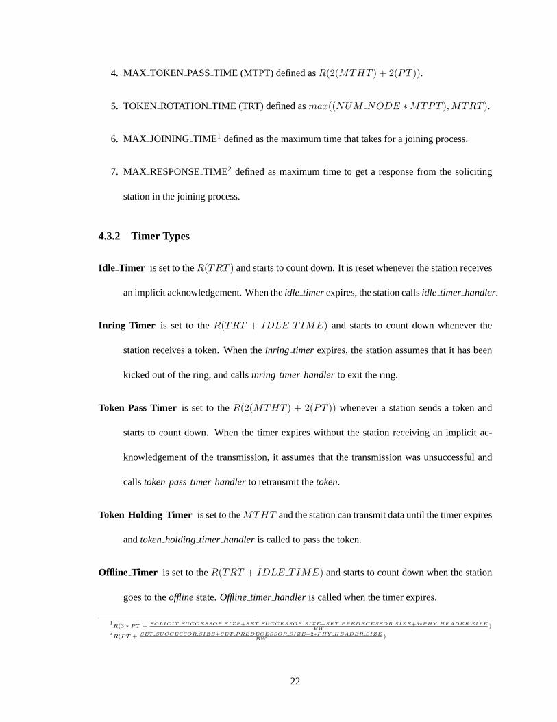
4. MAX TOKEN PASSTIME (MTPT) defined asR(2(MTHT ) + 2(PT )).
5. TOKEN ROTATION TIME (TRT) defined asmax((NUM NODE ∗MTPT ), MTRT ).
6. MAX JOINING TIME1 defined as the maximum time that takes for a joining process.
7. MAX RESPONSETIME2 defined as maximum time to get a response from the soliciting
station in the joining process.
4.3.2 Timer Types
Idle Timer is set to theR(TRT ) and starts to count down. It is reset whenever the station receives
an implicit acknowledgement. When theidle timerexpires, the station callsidle timer handler.
Inring Timer is set to theR(TRT + IDLE TIME) and starts to count down whenever the
station receives a token. When theinring timer expires, the station assumes that it has been
kicked out of the ring, and callsinring timer handlerto exit the ring.
Token PassTimer is set to theR(2(MTHT ) + 2(PT )) whenever a station sends a token and
starts to count down. When the timer expires without the station receiving an implicit ac-
knowledgement of the transmission, it assumes that the transmission was unsuccessful and
callstokenpasstimer handlerto retransmit thetoken.
Token Holding Timer is set to theMTHT and the station can transmit data until the timer expires
andtokenholding timer handleris called to pass the token.
Offline Timer is set to theR(TRT + IDLE TIME) and starts to count down when the station
goes to theofflinestate.Offline timer handleris called when the timer expires.
1R(3 ∗ PT + SOLICIT SUCCESSOR SIZE+SET SUCCESSOR SIZE+SET P REDECESSOR SIZE+3∗P HY HEADER SIZE
BW)
2R(PT + SET SUCCESSOR SIZE+SET P REDECESSOR SIZE+2∗P HY HEADER SIZE
BW)
22

Claim Token Timer is set to theR(TRT + TOKEN PASS TIME) and counts down at the
floatingstate. When expired, the station callsclaim tokentimer handlerto make aself ring.
Solicit SuccessorTimer is set to MAX JOINING TIME and when expired, the station callsso-
licit successorhandlerto sendsolicit successortoken.
Solicit Wait Timer is set toR(TOKEN PASS TIME) and when expired, the station calls
solicit wait handlerto pass thetoken.
Contention Timer is set to the MAXRESPONSETIME. When the invited station does not re-
ceivesetpredecessorfrom the soliciting node for CONTENTIONTIME, it assumes that it
has lost the contention process and callscontentiontimer handlerto go back tofloatingstate.
The timer values are arranged so that following relationship holds:
1. TOKEN HOLDING TIME < IDLE TIME < INRING TIME
2. MTRT3 ≤ IDLE TIME
4.3.3 Timer Handlers
Idle Timer Handler Station sendsclaim tokenandtokenand goes tomonitoringstate.
Inring Timer Handler Station goes tofloatingstate.
Offline Timer Handler Station goes tofloatingstate.
Claim Token Handler Station makesself ring, sendsclaim tokenand goes toidle state.
Solicit SuccessorHandler Station sendssolicit successortokenand goes tosolicitingstate.
3MTRT is the Maximum Token Rotation Time defined more precisely in Section 4.2 & 10.1
23

Token Holding Timer Handler Station passes thetokento its successor and goes tomonitoring
state.
Solicit Wait Handler Station goes to theidle state if it isself ring, otherwise, sendstokenand
goes tomonitoringstate.
Contention Timer Handler Station goes tofloatingstate.
Token PassTimer Handler Station retransmits token fornumtokenpasstry times, if it is unsuc-
cessful, the station sendssetpredecessortokento close the ring and goesofflinestate.
4.4 Frame Formats
4.4.1 Frame Control Field
1. Control Frame
0 0 C C C C C C
C C C C C C Type
0 0 0 0 0 0 TOKEN
0 0 0 0 0 1 CLAIM TOKEN
0 0 0 0 1 0 SOLICITSUCCESSOR
0 0 0 0 1 1 SETPREDECESSOR
0 0 0 1 0 0 SETSUCCESSOR
0 0 0 1 0 1 TOKENDELETED
2. Data Frame
F F M M M P P P
24
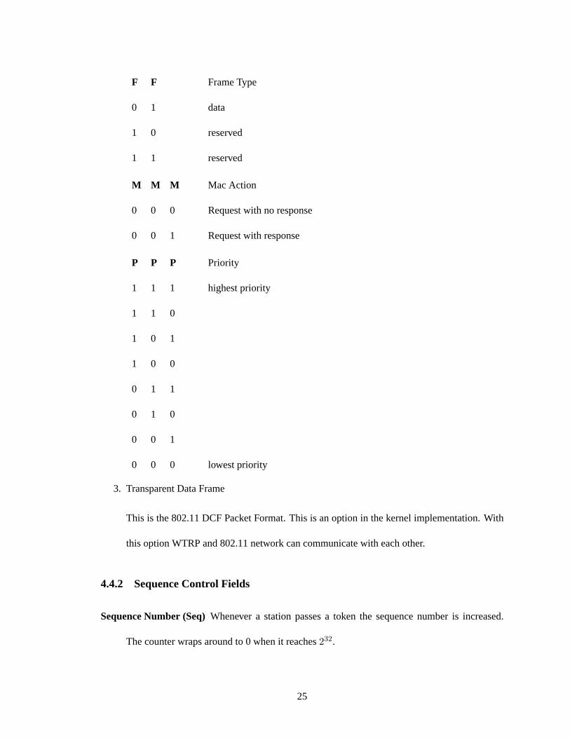
F F Frame Type
0 1 data
1 0 reserved
1 1 reserved
M M M Mac Action
0 0 0 Request with no response
0 0 1 Request with response
P P P Priority
1 1 1 highest priority
1 1 0
1 0 1
1 0 0
0 1 1
0 1 0
0 0 1
0 0 0 lowest priority
3. Transparent Data Frame
This is the 802.11 DCF Packet Format. This is an option in the kernel implementation. With
this option WTRP and 802.11 network can communicate with each other.
4.4.2 Sequence Control Fields
Sequence Number (Seq)Whenever a station passes a token the sequence number is increased.
The counter wraps around to 0 when it reaches232.
25

Generation Sequence Number (GenSeq)Whenever the owner of the token (the station that has
the same MAC address as the ring address of the token) passes the token, it increments the
generation sequence number. The counter wraps around when it reaches232.
Together the sequence number and the generation sequence number defines the priority of the
token. The priority is used for resolving multiple token resolution.
4.4.3 Address Fields
Destination Address Field (DA) The MAC address of the packet destination.
Source Address Field (SA)The MAC address of the packet source.
Ring Address Field (RA) The MAC address of the station that generated the token.
4.4.4 Admission Control Field
Number of Nodes (NoN) When the token rotates the owner calculates the number of nodes in the
ring by taking the difference between theSeqof the token andSeqof the node.
4.4.5 Queues
Data Packet QueueData packets coming from the upper layer are stored and transmitted when the
station gets the token.
Control Packet Queue Control packets if there is a failure in its transmission are stored and re-
transmitted.
4.4.6 Invalid Frame
We have assumed that the physical layer filters out the garbled packets. In addition the following
are invalid frames that the MAC layer can discard.
26

1. The FC field is undefined.
2. DA and SA are the same.
4.4.7 Frame Types
1. Token
0 0 0 0 0 0 0 0 RA DA SA NoN GenSeq Seq
1 6 6 6 2 4 4 bytes
The token is used to transfer the right to transmit.
2. Claim Token
0 0 0 0 0 0 0 1 RA Br. SA
1 6 6 6 bytes
The Claim Token is broadcast(Br.) when a station generates the token in the case where a
station creates a ring. It is also used when a station regains the token in the case of lost token.
3. Solicit Successor Token
0 0 0 0 0 0 1 0 RA Br. SA NoN NS
1 6 6 6 6 6 bytes
Thesolicit successortoken updates the successor field of a station. It is broadcast for inviting
another nodes to join the ring. NS field is to inform the joining node about its prospective
successor.
4. Set Predecessor Token
0 0 0 0 0 0 1 1 RA DA SA NoN GenSeq Seq
1 6 6 6 2 4 4 bytes
27

Thesetpredecessortoken updates the predecessor field of a station. It is used for both joining
the ring and exiting the ring.
5. Set Successor Token
0 0 0 0 0 1 0 0 RA DA SA NS
1 6 6 6 6 bytes
Theset successortoken updates the successor field of a station. It is used for both joining the
ring and exiting the ring.
6. Token Deleted Token
0 0 0 0 0 1 0 1 RA DA SA
1 6 6 6 bytes
The tokendeletedtoken is used to give predecessor notification that the token has been
deleted. This is to prevent the predecessor from invoke the ring recovery mechanism.
7. Data
0 1 M M M P P P RA DA SA Data
1 6 6 6 bytes
8. Transparent Data
FC Duration DA SA BSSID SC N/A Data CRC
2 2 6 6 6 2 6 0-2312 4 bytes
• FC - Frame Control:protocol version and frame type
• Duration - Time reserved for packet transmission
• BSSID - Basic Service Set ID
28
• SC - Sequence Control
• CRC -Cyclic Redundancy Check
4.5 Summary
WTRP is implemented as a Finite State Machine and each state has one or more timers. Timer
values are calculated from the MIB parameters. When it passes to a new state, a station initializes
the timers of the state and the handler function of the timer is called, when a timer expires. Tokens
have a three-dimensional priority; sequence number that is incremented in each passing, generation
sequence number that is incremented in each rotation by the owner, and ring address. In addition
to the token signal, WTRP introduces additional control signals involved in joining, leaving, and
failure recovery processes.
29
Chapter 5
Finite State Machine
5.1 Introduction
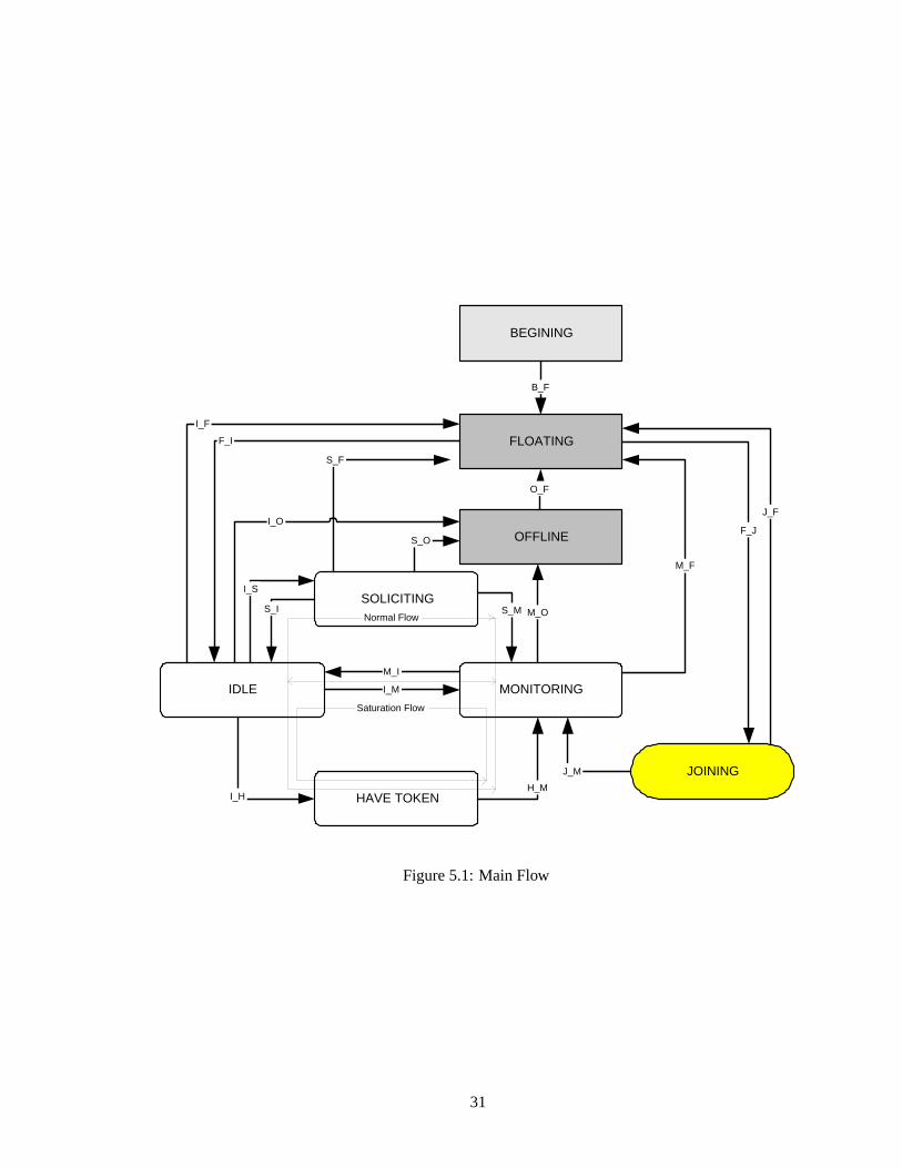
In this chapter, we describe the finite state machine in detail. Figure 8.1 shows the finite state
machine (FSM) of WTRP. The states are{ Beginning, Floating, Offline, Joining, Soliciting, Idle,
Monitoring, Have Token}. To cope with “mobility”, FSM hasjoining andsoliciting state where
inviting and joining processes are handled, “Interference avoidance” to other rings is done by intro-
ducingfloatingandofflinestates, whereby a station suspends transmission in these states and waits
to join a ring. “Collision avoidance” in the same ring is eliminated by theidle state, whereby a
station suspends transmission until it gets thetoken. “Equal bandwidth share” is controlled byhave
tokenstate whereby the station transmits packets as long as it is allowed.Monitoring state is for
“guaranteed transmission”, whereby a station checks its transmission and retransmits in case of a
failure. In the rest of the chapter, we describe the states and states transitions in detail.
30
IDLE MONITORING
SOLICITING
JOINING
HAVE TOKEN
BEGINING
OFFLINE
FLOATING
B_F
F_I
I_F
I_M
M_I
J_F
F_J
I_H H_M
J_M
O_F
S_O
S_F
S_I
I_S
M_O S_M
M_F
I_O
Saturation Flow
Normal Flow
Figure 5.1: Main Flow
31
BEGINNING FLOATING Always
Figure 5.2: Transition From/To Beginning State
5.2 States
5.2.1 Beginning State
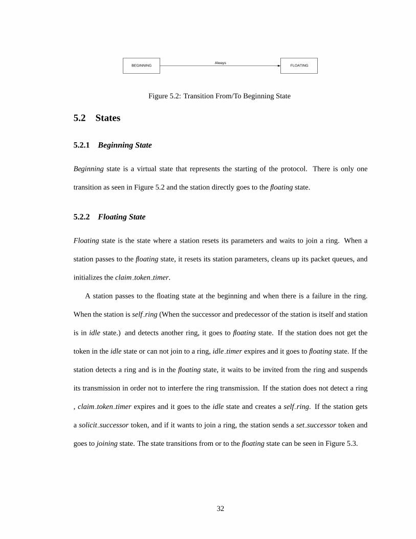
Beginningstate is a virtual state that represents the starting of the protocol. There is only one
transition as seen in Figure 5.2 and the station directly goes to thefloatingstate.
5.2.2 Floating State
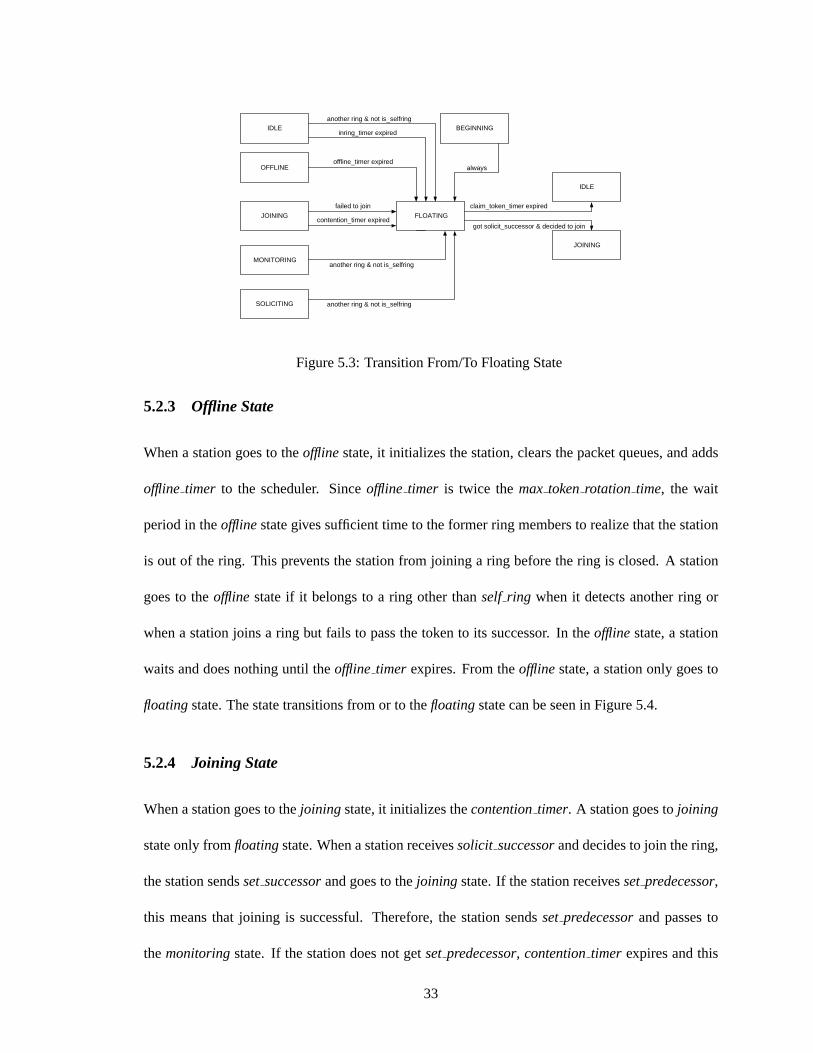
Floating state is the state where a station resets its parameters and waits to join a ring. When a
station passes to thefloatingstate, it resets its station parameters, cleans up its packet queues, and
initializes theclaim tokentimer.
A station passes to the floating state at the beginning and when there is a failure in the ring.
When the station isself ring (When the successor and predecessor of the station is itself and station
is in idle state.) and detects another ring, it goes tofloating state. If the station does not get the
token in theidle state or can not join to a ring,idle timer expires and it goes tofloatingstate. If the
station detects a ring and is in thefloating state, it waits to be invited from the ring and suspends
its transmission in order not to interfere the ring transmission. If the station does not detect a ring
, claim tokentimer expires and it goes to theidle state and creates aself ring. If the station gets
a solicit successortoken, and if it wants to join a ring, the station sends aset successortoken and
goes tojoining state. The state transitions from or to thefloatingstate can be seen in Figure 5.3.
32
JOINING FLOATING
IDLE
contention_timer expired
IDLE
SOLICITING
failed to join
another ring & not is_selfring
another ring & not is_selfring
claim_token_timer expired
OFFLINE
MONITORING
BEGINNING
JOINING
another ring & not is_selfring
offline_timer expired
inring_timer expired
always
got solicit_successor & decided to join
Figure 5.3: Transition From/To Floating State
5.2.3 Offline State
When a station goes to theofflinestate, it initializes the station, clears the packet queues, and adds
offline timer to the scheduler. Sinceoffline timer is twice themax tokenrotation time, the wait
period in theofflinestate gives sufficient time to the former ring members to realize that the station
is out of the ring. This prevents the station from joining a ring before the ring is closed. A station
goes to theoffline state if it belongs to a ring other thanself ring when it detects another ring or
when a station joins a ring but fails to pass the token to its successor. In theofflinestate, a station
waits and does nothing until theoffline timer expires. From theofflinestate, a station only goes to
floatingstate. The state transitions from or to thefloatingstate can be seen in Figure 5.4.
5.2.4 Joining State
When a station goes to thejoining state, it initializes thecontentiontimer. A station goes tojoining
state only fromfloatingstate. When a station receivessolicit successorand decides to join the ring,
the station sendsset successorand goes to thejoining state. If the station receivessetpredecessor,
this means that joining is successful. Therefore, the station sendssetpredecessorand passes to
themonitoringstate. If the station does not getsetpredecessor, contentiontimer expires and this
33

MONITORING OFFLINE FLOATING token_pass_timer expired
IDLE
SOLICITING
joined & failed to transmit
exceeded MAX_TOKEN_PASS_TRY
another ring & not is_selfring
another ring & not is_selfring
another ring & not is_selfring
offline_timer expired
Figure 5.4: Transition From/To Offline State
FLOATING JOINING
FLOATING
got solicit_successor & decided to join
failed to join
contention_timer expired
MONITORING
succeeded in joining
Figure 5.5: Transition From/To Joining State
means a failure in joining and the station goes back to thefloatingstate as seen in Figure 5.5.
5.2.5 Soliciting State
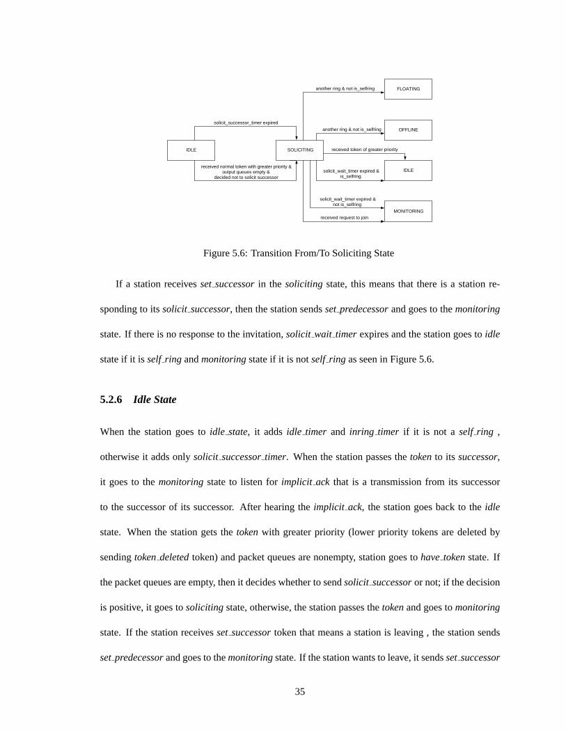
When a station goes to thesoliciting state, the station initializessolicit wait timer and sets the
station->numnode1 to MAX NoN+1 in order to suspend transmission of other stations if it is
not aself ring. When the station is in theidle state and receives thetoken, it checks its queues
and if they are empty, it decides to send solicit successor. If the decision is positive, then it
sendssolicit successortoken and goes to thesoliciting state. If the station isself ring, it addsso-
licit successortimer and when it expires, it sendssolicit successortoken and goes to the soliciting
state.
1stationstructure is defined more precisely in Section 6.4
34
SOLICITING
OFFLINE
MONITORING
solicit_successor_timer expired
another ring & not is_selfring
IDLE
IDLE
received request to join
FLOATING
received normal token with greater priority & output queues empty &
decided not to solicit successor
received token of greater priority
solicit_wait_timer expired & is_selfring
solicit_wait_timer expired & not is_selfring
another ring & not is_selfring
Figure 5.6: Transition From/To Soliciting State
If a station receivesset successorin the soliciting state, this means that there is a station re-
sponding to itssolicit successor, then the station sendssetpredecessorand goes to themonitoring
state. If there is no response to the invitation,solicit wait timer expires and the station goes toidle
state if it isself ring andmonitoringstate if it is notself ring as seen in Figure 5.6.
5.2.6 Idle State
When the station goes toidle state, it adds idle timer and inring timer if it is not a self ring ,
otherwise it adds onlysolicit successortimer. When the station passes thetokento its successor,
it goes to themonitoringstate to listen forimplicit ack that is a transmission from its successor
to the successor of its successor. After hearing theimplicit ack, the station goes back to theidle
state. When the station gets thetokenwith greater priority (lower priority tokens are deleted by
sendingtokendeletedtoken) and packet queues are nonempty, station goes tohavetokenstate. If
the packet queues are empty, then it decides whether to sendsolicit successoror not; if the decision
is positive, it goes tosoliciting state, otherwise, the station passes thetokenand goes tomonitoring
state. If the station receivesset successortoken that means a station is leaving , the station sends
setpredecessorand goes to themonitoringstate. If the station wants to leave, it sendsset successor
35

IDLE HAVE TOKEN
SOLICITING
inring_timer expired
another ring & not is_selfring
FLOATING
MONITORING
idle_timer expired
FLOATING
received normal token with greater priority & output queues is non empty
solicit_successor_timer expired
received implicit_ack
claim_token_timer expired
another ring & not is_selfring
OFFLINE
SOLICITING
MONITORING
received normal token with greater priority & output queues is empty &
decided to solicit successor
received normal token with greater priority & output queues is empty &
decided no to solicit successor & solicit_successor_timer expired.
received set_predecessor with greater priority
received set_successor
solicit_wait_timer expired & is_selfring
got token of greater priority
Figure 5.7: Transition From/To Idle State
and goes toofflinestate. The detailed state transition ofidle state can be seen in Figure 5.7.
5.2.7 Monitoring State
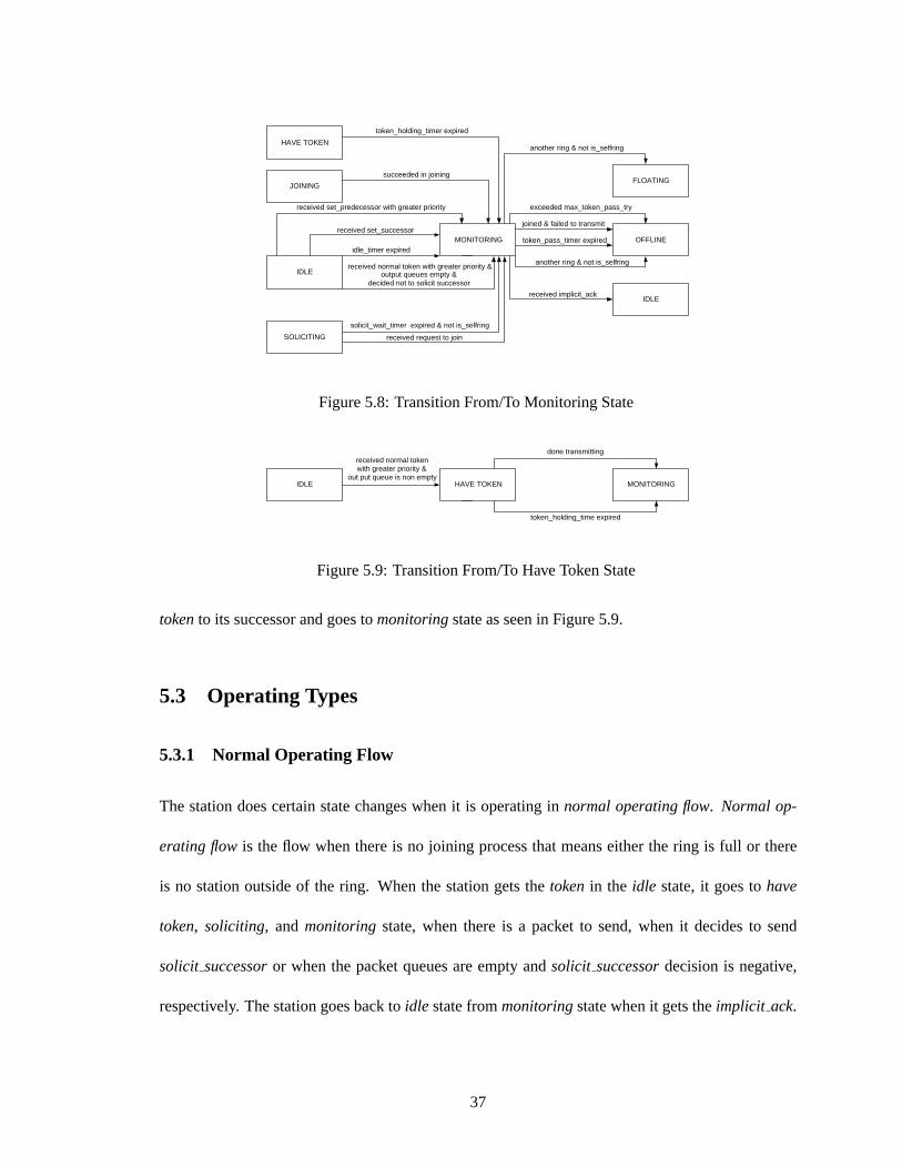
When the station goes to themonitoringstate, it resetsnumtokenpasstry and addstokenpasstimer.
Monitoringstate is to monitor the medium in order to make sure that the transmission is successful.
Implicit ack is used to decide whether a transmission is successful or not. If there is a retransmis-
sion of the same token, the station sendstokendeletedtoken. Figure 5.8 shows the transition to and
from monitoringstate. If the transmission is successful , the station goes toidle state.
5.2.8 Have Token State
When the station goes to thehavetokenstate, it initializestokenholding timer. A station passes
to havetokenstate only from theidle state if it has packet to send. When a packet is transmitted
tx donehandleris called.Tx donehandlerchecks for the packet queues and transmits if those are
nonempty. When the queues are empty or thetokenholding timer is expired, the station passes the
36
MONITORING OFFLINE
HAVE TOKEN
SOLICITING
idle_timer expired
another ring & not is_selfring
received request to join
JOINING
IDLE
IDLE
succeeded in joining
token_holding_timer expired
solicit_wait_timer expired & not is_selfring
FLOATING
received normal token with greater priority & output queues empty &
decided not to solicit successor
received set_successor
received set_predecessor with greater priority
received implicit_ack
exceeded max_token_pass_try
token_pass_timer expired
joined & failed to transmit
another ring & not is_selfring
Figure 5.8: Transition From/To Monitoring State
IDLE HAVE TOKEN MONITORING
received normal token with greater priority &
out put queue is non empty
done transmitting
token_holding_time expired
Figure 5.9: Transition From/To Have Token State
tokento its successor and goes tomonitoringstate as seen in Figure 5.9.
5.3 Operating Types
5.3.1 Normal Operating Flow
The station does certain state changes when it is operating innormal operating flow. Normal op-
erating flowis the flow when there is no joining process that means either the ring is full or there
is no station outside of the ring. When the station gets thetokenin the idle state, it goes tohave
token, soliciting, andmonitoring state, when there is a packet to send, when it decides to send
solicit successoror when the packet queues are empty andsolicit successordecision is negative,
respectively. The station goes back toidle state frommonitoringstate when it gets theimplicit ack.
37

5.3.2 Saturation Operating Flow
The station operates in saturation condition when there are always packets to send. In this case,
the station passes to thehavetokenstate from theidle state and keeps sending packets until theto-
kenholding timer is expired. The station passes to themonitoringstate after passing thetokento its
successor, and goes back toidle state after receivingimplicit ackas seen in Figure 8.1. The differ-
ence betweennormalandsaturationoperating flow is that the latter does not sendsolicit successor
and state transitions always follow theidle, have tokenandmonitoringorder, whereas the former
does not follow an ordered state transition.
5.4 Summary
In WTRP, a station changes its state upon packet reception, packet transmission, or timer expiration.
Floatingandofflinestates are the states where the station only listens to the medium. In these states,
the station does not belong to any ring. When a station belongs to a ring, it waits fortokenin theidle
state and passes tohavetokenstate if it has data to send. If the station has enough time, it may send
solicit successortoken and pass tosoliciting state. When a station wants to join a ring, it responds
to a solicit successortoken and passes tojoining state. The station confirms its transmissions in
monitoringstate. A station traverse aroundidle, have token , solicitingandmonitoringstates when
it operates innormaloperating conditions. If it operates insaturationcondition, the station follows
idle, have token, monitoringstates in order.
38

Chapter 6
Implementation Overview
6.1 Introduction
Wireless Token Ring Protocol is deployed in three modes:{Simulator, User-Space, and Kernel
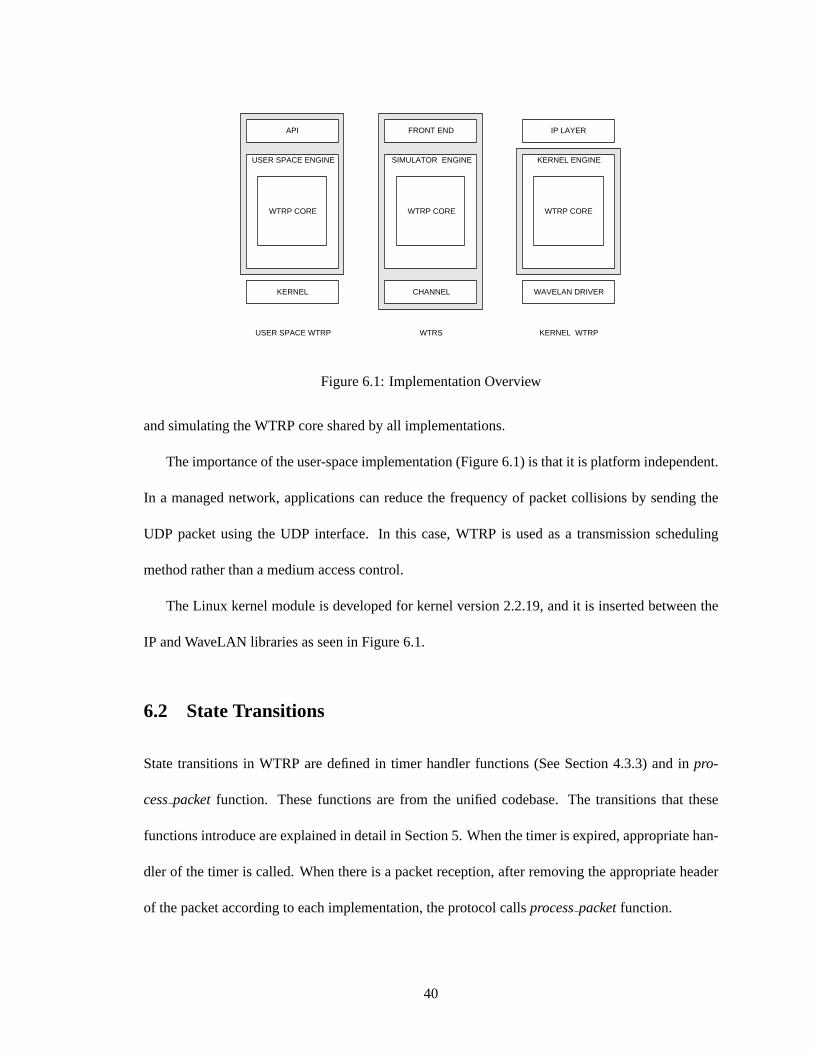
Implementations}. We create a unified codebase that is shared by all the implementations. The main
core of the protocol is the same for all three implementation and each implementation introduces
certain hooks to the main core as seen in Figure 6.1. This unified codebase is made possible by
the implementation of Linux kernel libraries for packet manipulations and event scheduling in user
space.
Ad hoc networks are now being designed that can scale to very large configurations. Design and
development costs for such systems could be significantly reduced if there were efficient techniques
for evaluating design alternatives and predicting their impact on overall system performance metrics.
Simulation is the most common performance evaluation technique for such systems. The simulator
we developed attempts to address design and development cost reduction by providing an easy path
for migration of simulation models to operational software prototypes and support for visual and
hierarchical model design. The Wireless Token Ring Simulator (See Figure 6.1) allows debugging
39
KERNEL
IP LAYER
WAVELAN DRIVER
USER SPACE WTRP WTRS KERNEL WTRP
FRONT END
CHANNEL
WTRP CORE
SIMULATOR ENGINE
API
WTRP CORE
USER SPACE ENGINE
WTRP CORE
KERNEL ENGINE
Figure 6.1: Implementation Overview
and simulating the WTRP core shared by all implementations.
The importance of the user-space implementation (Figure 6.1) is that it is platform independent.
In a managed network, applications can reduce the frequency of packet collisions by sending the
UDP packet using the UDP interface. In this case, WTRP is used as a transmission scheduling
method rather than a medium access control.
The Linux kernel module is developed for kernel version 2.2.19, and it is inserted between the
IP and WaveLAN libraries as seen in Figure 6.1.
6.2 State Transitions
State transitions in WTRP are defined in timer handler functions (See Section 4.3.3) and inpro-
cesspacketfunction. These functions are from the unified codebase. The transitions that these
functions introduce are explained in detail in Section 5. When the timer is expired, appropriate han-
dler of the timer is called. When there is a packet reception, after removing the appropriate header
of the packet according to each implementation, the protocol callsprocesspacketfunction.
40

6.3 Data Flow
Data packets coming from the medium are processed first in theprocesspacketand thenapp rx is
called. Data coming from the upper layer is first queued and then transmitted to the medium when
the station gets thetoken. Successful transmission is notified to the protocol bytx donehandlerthat
re-checks the queues. If the queue is empty, the protocol passes thetoken, otherwise, sends another
packet.
6.4 Data Structures
Stationanddevicestructure are the main structures that preserve the station information and im-
plementation specific information respectively.Stationstructure contains the protocol state and is
encapsulated in thedevicestructure that contains the implementation parameters.
6.4.1 StationStructure
In the stationStructure, protocol parameters of the station are kept which include{Identification,
MIB, Ring Statistic, Joining and Monitoring Parameters, Timers, Packet Queues, Connectivity Ta-
ble}.
Identification Parameters
A node is identified by MAC address of the node (TS), MAC address of the previous node (PS),
MAC address of the next node (NS), MAC address of the ring owner (RA), Sequence Number of
the node (seq), Generation Sequence Number of the node (genseq).
MIB Parameters
User specified parameters (See Section 4.2) are also pointed in thestationstructure.
41
Ring Statistic Parameters
The station calculates the number of nodes in the ring (numnode) by subtracting theseqof the
token from theseqof station since in the rotation,seqnumber of the token is incremented by each
station. Token rotation time (lastaccepted) is calculated by taking the difference of two successive
tokenarrival times.
Joining Parameters
When a station wants to join a ring, the station setswantsto join to true. After getting an in-
vitation from a station, it sets thesoliciting station to the address of inviting station andsolic-
iting stationsuccessoras the successor of the inviting station. This information is sent withso-
licit successortoken(See Section 4.4.7).
Monitoring Parameters
The station tries up tonumtokenpasstry before giving up passing token and exiting.
Timers
Stationstructure contains the timers. A timer is initialized byinit timer function which creates the
timer structure by assigning the appropriate handler to thehandlerpointer,devicestructure to the
datapointer and timer value to theexpirationpointer of the timer structure.
Packet Queues
Stationstructure contains pointers to two queues;out bufferedqueuewhich is the queue for data
packets that are buffered for later transmission andout tx queuewhich is the queue for the packets
that are ready to be transmitted, but blocked due to hardware being busy (packet can be blocked due
42
to carrier sensing).
Connectivity Tables
Pointer to connectivity tables of the station is contained in thestationstructure. The connectivity
table (my ctable) holds information about local transmissions that are from the station‘s ring. The
other connectivity table (other ctable) holds information about all transmissions in the reception
range.
Initialize station
Station is initialized byinitialize station function, When the function is called, all the parameters
are set to default values.
6.4.2 DeviceStructure
Devicestructure contains the protocol information and implementation specific parameters. In the
simulator implementation, position and velocity information, seed of the random variable, move-
ment pattern, application list is contained here. In the user-space implementation, socket informa-
tion is kept here.Stationinformation is casted out from thedevicestructure when it is passed to a
function as an input.
6.5 Summary
In this chapter, we presented the approach that we take when designing the WTRP Implementations.
WTRP has three deliverables; User-Space, Simulator, Kernel implementations. We created a uni-
fied codebase for each implementation. Common structures are presented.Stationstructure keeps
protocol parameters anddevicestructure containsstationstructure and implementation parameters.
43

User-Space implementation is a platform independent scheduler, Simulator is a tool to simulate the
WTRP in wireless environment and do some performance analysis, and Kernel Implementation is a
Linux link layer module.
44
Chapter 7
Wireless Token Ring Simulator
7.1 Introduction
WTRS (Wireless Token Ring Simulator) is a simulation library for Wireless Token Ring protocol.
It is built on top of the WTRP Core that provides the finite state machine of the WTRP. It has
been designed and built with the primary goal of simulating the actual implementation code in
large network models that can scale up to a hundred or thousand nodes. This design of simulator
is advantageous since it eliminates the need to develop separate program for simulation and for
deployment. The separated development is not only expensive in terms of added developmental
costs, but also increases the chance of failure to identify potential problems of the protocol since the
protocols that are tested in simulations and deployed are often different.
As most network systems adopt a layered architecture, WTRS is being designed using a layered
approach similar to the OSI seven-layer network architecture. Simple APIs are defined between
different simulation layers. This allows the rapid integration of models developed at different layers
by different people. Actual implementation code can be easily integrated into WTRS with this
layered design. Now, WTRP was implemented in MAC layer.
45
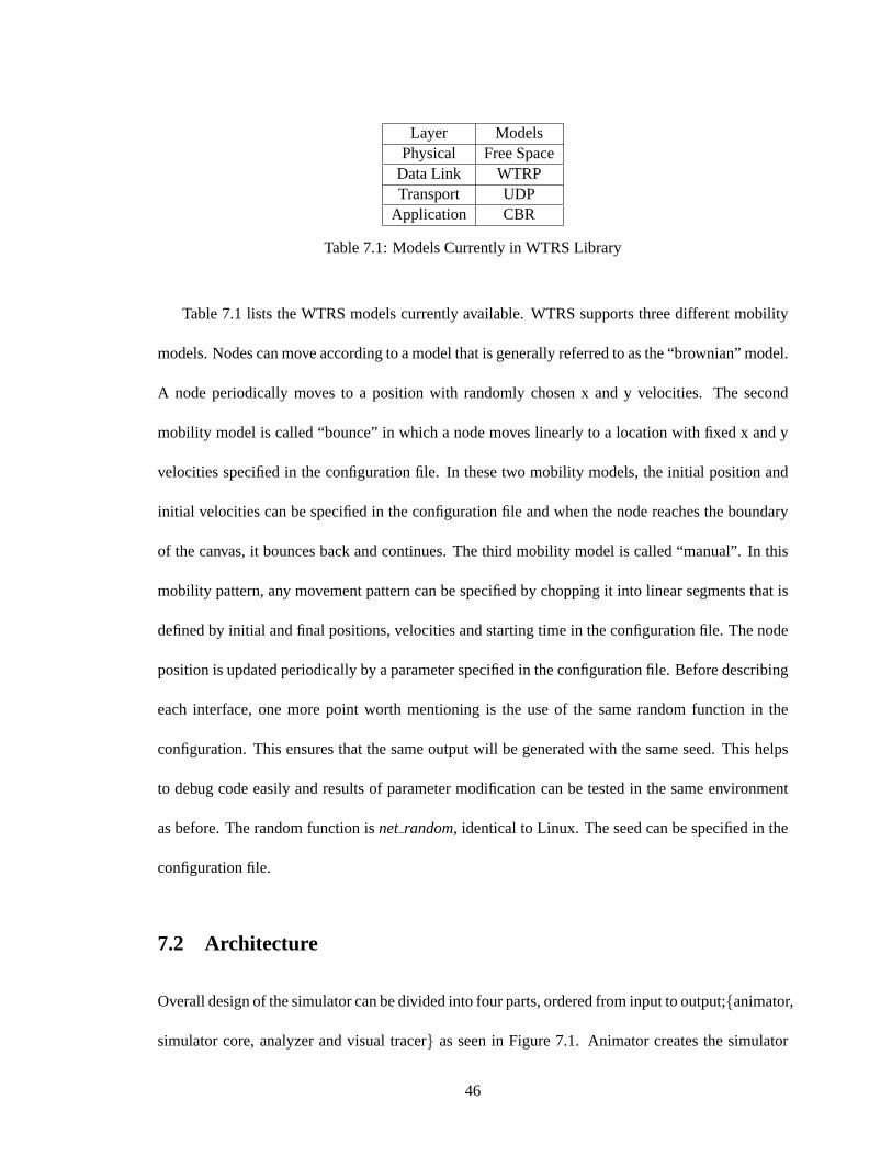
Layer ModelsPhysical Free Space
Data Link WTRPTransport UDP
Application CBR
Table 7.1: Models Currently in WTRS Library
Table 7.1 lists the WTRS models currently available. WTRS supports three different mobility
models. Nodes can move according to a model that is generally referred to as the “brownian” model.
A node periodically moves to a position with randomly chosen x and y velocities. The second
mobility model is called “bounce” in which a node moves linearly to a location with fixed x and y
velocities specified in the configuration file. In these two mobility models, the initial position and
initial velocities can be specified in the configuration file and when the node reaches the boundary
of the canvas, it bounces back and continues. The third mobility model is called “manual”. In this
mobility pattern, any movement pattern can be specified by chopping it into linear segments that is
defined by initial and final positions, velocities and starting time in the configuration file. The node
position is updated periodically by a parameter specified in the configuration file. Before describing
each interface, one more point worth mentioning is the use of the same random function in the
configuration. This ensures that the same output will be generated with the same seed. This helps
to debug code easily and results of parameter modification can be tested in the same environment
as before. The random function isnet random, identical to Linux. The seed can be specified in the
configuration file.
7.2 Architecture
Overall design of the simulator can be divided into four parts, ordered from input to output;{animator,
simulator core, analyzer and visual tracer} as seen in Figure 7.1. Animator creates the simulator
46

ANIMATOR GUI
CHANNEL
NODE 1
NODE 2
WTRP FSM
SCHEDULER
INITIALIZER
VISUAL TRACER GUI
NODE N
CBR
NODE 3 ...
ANALYZER GUI
RECORDER
Figure 7.1: Overall Design
configuration information. The simulator core is the main part where the simulator engine, channel
model, data application and WTRP module are located. Visual Tracer and Analyzer process the
output files generated by the simulator. Currently, NAM [20] is used for visualization and analyzer
file format is the same as that of NS [21] trace file.
7.2.1 Animator
As we mentioned before, simulation parameters are defined in animator. A snapshot of the GUI can
be seen in Figure 7.2. Parameters of the simulation are shown in Table 7.2. These parameters are
used as an input to the Simulator Engine (See Figure 7.1) and used at the initialization.
47

Parameter DefinitionCanvas size Determines the size of the topologyVisual tracer output File Name for NAMAnalyzer output File Name for log infoSimulation time Determines the execution timeRandom Seed Controls the outcome of the simulationRecord Function Frequency Controls the output file sizeNodes & Nodes Address Node Identification ParametersMovement Patterns Defines the movement patterns of the nodesNodes Topology Information Defines the velocity and initial and final position informationConstant Bit Rate (CBR) ApplicationsDefines the application information
Table 7.2: Configuration Parameters
Figure 7.2: Animator GUI
48

Figure 7.3: Visual Tracer
7.2.2 Visual Tracer & Analyzer
For visualization, a topological snapshot of the simulation is taken periodically and recorded in a
trace file. The trace file is in NAM format and is viewed with NAM [20]. A screen shot of the
visualization is shown in Figure 7.3. Movement, transmission, reception and ring address can be
observed from the Visual Tracer.
We created a set of libraries that can be used to record performance-related events for Analyzer.
We have implementedrecord packettransmissionandrecord packetreceptionfunctions that write
detailed information about that packet and station to the analyzer output file.
49
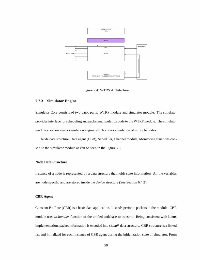
CBR
WTRP
CHANNEL PROPAGATION MODEL/MOBILITY MODEL
SCHEDULER
MONITORING
APPLICATION
MAC
UDP/IP
Figure 7.4: WTRS Architecture
7.2.3 Simulator Engine
Simulator Core consists of two basic parts: WTRP module and simulator module. The simulator
provides interface for scheduling and packet manipulation code to the WTRP module. The simulator
module also contains a simulation engine which allows simulation of multiple nodes.
Node data structure, Data agent (CBR), Scheduler, Channel module, Monitoring functions con-
stitute the simulator module as can be seen in the Figure 7.1.
Node Data Structure
Instance of a node is represented by a data structure that holds state information. All the variables
are node specific and are stored inside thedevicestructure (See Section 6.4.2).
CBR Agent
Constant Bit Rate (CBR) is a basic data application. It sends periodic packets to the module. CBR
module usestx handler function of the unified codebase to transmit. Being consistent with Linux
implementation, packet information is encoded intosk buff data structure. CBR structure is a linked
list and initialized for each instance of CBR agent during the initialization state of simulator. From
50
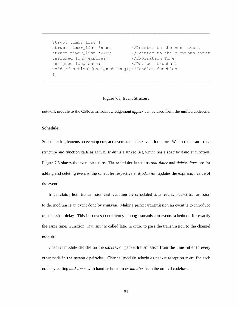
__________________________________________________________________
struct timer_list {struct timer_list *next; //Pointer to the next eventstruct timer_list *prev; //Pointer to the previous eventunsigned long expires; //Expiration Timeunsigned long data; //Device structurevoid(*function)(unsigned long);//Handler function};
__________________________________________________________________
Figure 7.5: Event Structure
network module to the CBR as an acknowledgementapp rx can be used from the unified codebase.
Scheduler
Scheduler implements an event queue, add event and delete event functions. We used the same data
structure and function calls as Linux.Eventis a linked list, which has a specific handler function.
Figure 7.5 shows the event structure. The scheduler functionsadd timer anddeletetimer are for
adding and deleting event to the scheduler respectively.Mod timer updates the expiration value of
the event.
In simulator, both transmission and reception are scheduled as an event. Packet transmission
to the medium is an event done bytransmit. Making packet transmission an event is to introduce
transmission delay. This improves concurrency among transmission events scheduled for exactly
the same time. Functiontransmit is called later in order to pass the transmission to the channel
module.
Channel module decides on the success of packet transmission from the transmitter to every
other node in the network pairwise. Channel module schedules packet reception event for each
node by callingadd timer with handler functionrx handlerfrom the unified codebase.
51
Channel Module
In terms of the channel model, the simulator models a simple Direct Sequence Spread Spectrum
(DSSS) capturing effect based on signal to interference ratio, free space propagation, and underlying
CSMA radio. Multipath or fading affect is not modelled. Packet Loss is modelled based on distance
and power and packet corruption is modelled based on Signal to Interference Ratio.
Monitoring
Topology monitoring functions record NAM position information of the nodes by a periodic event
calledrecord function. Periodicity of the event is set by a parameter in the configuration file. As
a result, we can adjust recording period to reduce the size of output file at the expense of brittle
movements of nodes. Monitoring functions mark the node with different color, shape or character
for the duration of reception. Currentlystart transmissionhighlights transmitting station red and
start receptionmarks the receiving station green and ring address of the node is marked on top of
it. A snap shot of the NAM can be seen in Figure 7.3.
Therecord transmissionandrecord receptionfunctions are used for the analyzer output file in
order to keep a log of the packet events. These functions create a log of information of the packet
header with a time stamp.
After discussing basic hookups of the simulator, We can investigate the simulator run in more
detail.
7.2.4 Simulator Run
Simulator starts with initialization process. The initialization steps are as follows:
1. Initialize simulation
52
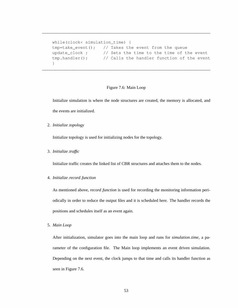
__________________________________________________________________
while(clock< simulation_time) {tmp=take_event(); // Takes the event from the queueupdate_clock ; // Sets the time to the time of the eventtmp.handler(); // Calls the handler function of the event}
__________________________________________________________________
Figure 7.6: Main Loop
Initialize simulation is where the node structures are created, the memory is allocated, and
the events are initialized.
2. Initialize topology
Initialize topology is used for initializing nodes for the topology.
3. Initialize traffic
Initialize traffic creates the linked list of CBR structures and attaches them to the nodes.
4. Initialize record function
As mentioned above,record functionis used for recording the monitoring information peri-
odically in order to reduce the output files and it is scheduled here. The handler records the
positions and schedules itself as an event again.
5. Main Loop
After initialization, simulator goes into the main loop and runs forsimulationtime, a pa-
rameter of the configuration file. The Main loop implements an event driven simulation.
Depending on the next event, the clock jumps to that time and calls its handler function as
seen in Figure 7.6.
53

7.3 Summary
Simulator is designed for the purpose of simulating the actual code in a wireless environment with
multiple nodes. The initial aim of the simulator is to facilitate the implementation code and do
rudimentary performance analysis. An instance of a node is represented by a data structure that
holds state information, and the code base of the WTRP module provides rules for state transitions.
Delay in events and timer functions are implemented as scheduling of events to be executed later.
The scheduler takes the event, runs the code, and then adds the event. This cycle runs the simulation.
54
Chapter 8
User Space Implementation
8.1 Introduction
WTRP manages the medium by scheduling the transmission. Stations start transmitting upon recep-
tion of a token and are forced to stop transmitting after a fixed time. This idea can be considered as
a scheduler and extended to be used by the applications to reduce the frequency of packet collisions
among the application that runs on top of WTRP. User-Space Implementation deploys this sched-
uler idea and is designed for applications using the UDP socket. The implementation is designed in
the application layer in order to be platform independent. Applications use the provided WoW API
[3] (Web Over Wireless Application Program Interface) and WoW API re-routes the UDP packets
to the WTRP module that sits in the application layer and WTRP module does the scheduling.
8.2 Implementation
8.2.1 Initialization
User Space implementation uses IP address instead of MAC address to distinguish a node. An
node reads the IP address from(/etc/hosts)in Linux . In the initialization state,init stationcalls
55
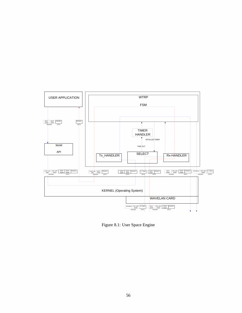
USER APPLICATION
WoW
API
KERNEL (Operating System)
Tx_HANDLER Rx-HANDLER SELECT
WAVELAN CARD
WTRP
FSM
TIMER HANDLER
DEST ADDR
DEST PORT
PACKET
DEST PORT
PACKET
DATA HEADER
DATA
INITIALIZE TIMER
TIME OUT
TOK_DEV PORT
DEST ADDR
DEST PORT
PACKET
DATA HEADER
Local Loop Addr
TOK_APP PORT
DEST ADDR
DEST PORT
PACKET
DATA HEADER
DEST PORT
PACKET Local Loop Addr
DATA HEADER
DEST ADDR
DEST PORT
PACKET
DATA
TOK_DEV PORT
DEST ADDR
DEST PORT
PACKET
DATA HEADER
X_Token Broadcast
DATA HEADER
TOK_DEV PORT
PACKET
DATA
X_Token
DATA
X_Token Broadcast
DATA HEADER
TOK_DEV PORT
Figure 8.1: User Space Engine
56

initialize stationfrom unified codebase to create thestationparameters andinit timer for all WTRP
timers (See Section 4.3). At the end,init stationstarts the station infloating state if theIOCTL
option is not set. WhenIOCTL option is set, station waits to join a ring until it gets “request
medium” system call from an application.
UDP sockets are used for packet transmission and reception. UDP ports are open for appli-
cations and the medium byinitialize socket. Applications useTOK APP PORT to send packet
to WTRP Module or receive packet from WTRP module via local loop. WTRP module uses
TOK DEV PORT when sending packet to the medium or receiving from the medium as seen in
Figure 8.1.
8.2.2 System Call (IOCTL)
System Call (IOCTL) is implemented to control the WTRP module from the application. When
IOCTLoption is set, the station waits for a request from an application. Request is sent through the
local loop to the WTRP module and if the request isREGISTER, the application that is registering
is added to the application list of the station. If the request isJOIN, station goes tofloating state
to join a ring. If the request isLEAVE, station leaves the ring after getting the token. The request
GET INFO sends thestationparameters to the application.
8.2.3 Application Interface (WoW API)
Application Interface (WoW API) is a set of functions that can be used by datagram applications
to use the protocol developed in user space. The idea in the API is that an application uses WOW
socket functions instead of the Linux socket functions. The Linux socket functions{socket, bind,
recvfrom, sendto} are replaced by{my socket, mybind, myrecvfrom, mysendto} respectively.
my ioctl is introduced forIOCTL option similar to theioctl system call in Linux.
57
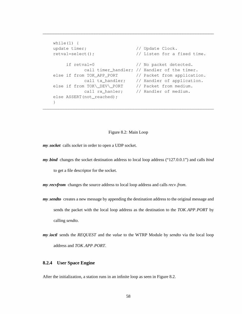
__________________________________________________________________
while(1) {update timer; // Update Clock.retval=select(); // Listen for a fixed time.
if retval=0 // No packet detected.call timer_handler; // Handler of the timer.
else if from TOK_APP_PORT // Packet from application.call tx_handler; // Handler of application.
else if from TOK\_DEV\_PORT // Packet from medium.call rx_hanler; // Handler of medium.
else ASSERT(not_reached);}
__________________________________________________________________
Figure 8.2: Main Loop
my socket callssocketin order to open a UDP socket.
my bind changes the socket destination address to local loop address (“127.0.0.1”) and callsbind
to get a file descriptor for the socket.
my recvfrom changes the source address to local loop address and callsrecv from.
my sendto creates a new message by appending the destination address to the original message and
sends the packet with the local loop address as the destination to theTOK APP PORT by
callingsendto.
my ioctl sends theREQUESTand thevalue to the WTRP Module bysendtovia the local loop
address andTOK APP PORT.
8.2.4 User Space Engine
After the initialization, a station runs in an infinite loop as seen in Figure 8.2.
58
Scheduling function,select, listens to two ports,TOK DEV PORTandTOK APP PORT, for
a certain amount of time that is determined by expiration value of the initialized timer. Function
selectreturns positive if there is a packet in the ports or returns zero if the timer expires. If there
is no packet, the protocol calls thehandler function of the timer. If theselectfunction returns
because of a packet in theTOK APP PORT, the protocol calls thetx handler. If the packet is in
theTOK DEV PORT, the protocol calls therx handler. As can be seen in Figure 8.1, packets from
the application are handled by thetx handler and packets from the medium are handled by the
rx handler.
8.2.5 Transmission
When an application sends a packet to the medium, the packet is modified and directed to the
WTRP module by WOW API (See figure 8.1) and the protocol callstx handler. Functiontx handler
examines the data and the destination, and callsprocesspacket if the destination is local loop;
otherwise, it callstok tx handler. Processpacketis called because if the destination is local loop,
this means that two applications at the same station are communicating, therefore the packet should
be directly forwarded to the destination. Functiontok tx handler puts the packet to the packet
queue to be transmitted after the station gainstoken. When the station gets thetoken, station sends
the packet to its destination through theTOK DEV PORT with destination port appended to the
data as seen in Figure 8.1. Control packets are broadcast through theTOK DEV PORT.
8.2.6 Reception
Similar to the MAC layer, all packets received from the medium are from theTOK DEV PORT
captured by therx handlerthat callstok rx handler. Functiontok rx handlercallsprocesspacket
from the unified codebase.processpacketexamines the packet and if it is a data packet, it calls
59
app rx in order to send it to the application via the local loop. If the packet is control packet,
processpacketprocesses the packet and executes the corresponding state transitions.
8.3 Summary
User-Space implementation is a platform independent implementation running in the application
layer for applications that uses UDP sockets. The implementation uses UDP sockets to communi-
cate with the applications and the medium. A UDP interface is provided for applications in order
to re-direct their packets to the WTRP module. If theIOCTL option is set, an application can send
commands to the ring by theIOCTL calls. A station attempts to join or leave a ring after getting
the corresponding system signal from the application. Linux scheduling function,select, listens to
the application and medium sockets for the corresponding expiration value of the state timer. Three
events drive the implementation. Timer handler is called when there is no packet. Application han-
dler is called when the packet is from an application. Finally, medium handler is called when the
packet is from the medium. Outcomes of these events are inputs to the WTRP module.
60
Chapter 9
Kernel Implementation
9.1 Introduction
In this chapter, we present the detailed description of the Kernel Implementation. Kernel Implemen-
tation is a link-layer module, derived from the unified codebase. Some of the kernel functions and
data structures are used in non-kernel code. These functions are scheduling functions and socket
buffer data structure. The Linux protocol stack does not maintain layering below the network layer.
It performs some rudimentary logical link control functions itself and delegates the rest of these low-
level functions to the device where it is integrated. While this may lead to better performance, for
research and development of link-layer protocols we prefer to retain the full layering in a completely
modular way as in ISO layering model (See Table 9.1).
We first explain the usual path between the network device and the network-layer protocols, and
then the path taken by our implementation. Every computer requires peripheral hardware devices
to operate. Each device plugs into some type of port or socket. This port or socket may be part of
an interface card which plugs into the system bus; or the socket itself may be on the bus, as in the
case of PCMCIA sockets [24]. In any case, to the computer, the peripheral device is an entity at a
61

Layer 7 Application LayerLayer 6 Presentation LayerLayer 5 Session LayerLayer 4 Transport LayerLayer 3 Network LayerLayer 2 Data Link LLC (Logical Link Control) Sublayer
MAC (Medium Access Control) SublayerLayer 1 Physical Layer
Table 9.1: ISO Layering Model
particular address which sends and receives data over the bus. When the device has data to send over
the bus, it must interrupt the computer so that the computer can stop whatever it is doing, receive the
data, and respond appropriately. Thus, each device has a unique IRQ number. When the operating
system, in this case Linux, receives an interrupt, it passes control to the interrupt handler registered
for that IRQ, usually in the device driver which is bound to that device. This interrupt handler does
the necessary processing of the information received from the device, before returning control to the
operating system. It must be fast and efficient, because while it is handling this interrupt, interrupts
are disabled: no other device can interrupt the system.
One function of the device driver is to handle interrupts from the device. Another function is
to send data to the device, perhaps to control it or perhaps to transmit through the device (such
as a networking device). In this way, the kernel does not have to know all the details about the
communication through well-defined interfaces, and it is up to the device driver to interpret between
such an interface and its particular device or class of devices.
In the early days of Linux, all device drivers were built into the kernel image loaded at boot
time. But this quickly became impractical, so now most device drivers are also available as modules
which can be loaded or unloaded as needed, while the operating system is running. In any case,
the device driver must be bound to the particular device for which it is responsible. That is, it must
know the IRQ of the device so it can register to receive interrupts from that device, and it must know
62
the address at which it can communicate to the device. This may happen through parameters passed
to the device driver module when it is loaded, through autoprobing, or through some other means
such as the Card Services daemon.
In the case of network devices, Linux treats each device as an abstraction defined by adevice
data structure (net devicein kernel version 2.4). This structure1 conventionally referenced through
a pointer asstruct device∗ dev, includes several function pointers as well as some data fields. These
define the API through which the kernel interacts with the device. It is the responsibility of the
device driver to allocate this structure, fill in the function pointers and the data fields appropriately,
and register the device with kernel. A network device usually issues interrupts for two reasons: to
notify the system that it has received a packet, or to notify the system that it has finished transmitting
and is ready for more packets. The device driver must register itself to receive these interrupts and
handle them appropriately. Linux handles all networking packets through an abstraction called a
socket buffer, defined by ask buff data structure. This structure2 conventionally referenced through
a pointer asstruct skbuff ∗skb, contains many data fields specially adapted for networking. The
most important of these, of course, is data, which contains the actual data in the packet. However,
this is not as simple as it seems; thesk buff structure is allocated just once and passed up or down
through all layers,skb->datashrinks as each layer interprets its own header and respective header
so it is still accessible. All this is done through pointer manipulations with a minimum of copying or
reallocation of memory. In between some of these stages, theskbmay be placed on various queues
to await processing, so it also includes links for this purpose. When a device receives a packet, it
issues an interrupt which is serviced by the device driver. The interrupt handler in the device driver
allocates astruct skbuff structure and copies the data into this structure. It then reads the link layer
header to determine which protocol (usually, a network layer protocol) should handle the packet
1The structure is defined in/usr/src/linux/include/linux/netdevice.h2The structure is defined in/usr/src/linux/include/skbuff.h
63

next. It assigns this protocol to theskb->protocolfield, and then it callsnetif rx(skb). Finally the
interrupt handler exits, returning control to the operating system.
9.2 Kernel Modules
One of the useful things about Linux is its use of kernel modules. Kernel modules allow for the
expansion of the kernel code at run time. This means that we can compile individual modules
separately and attach them to the kernel when the system is running, instead of recompiling the
entire kernel.
9.3 Real Time Processes in Linux
The Linux kernel runs at 100 Hz by default in x86 compatible hardware and 1024Hz in Sun.
The 100 Hz clock translates into the clock granularity of 10ms. The coarse granularity creates
problems because WTRP runs much faster than 10ms, and the protocol uses many timers. To
combat this problem, one can increase the granularity of the clock by increasing the HZ value in
/usr/src/linux/asm-i386/param.hand then recompiling the kernel. Increasing the granularity results
in a more responsive system, however the price paid is the additional overhead of processing more
clock interrupts. We have increased the granularity of the clock on P3 500Hz and 700Hz laptops to
2048 Hz. This has resulted in reduced joining and fault recovery time and increased stability of the
token ring.
9.4 Old tale of WaveLAN
Old tale of WaveLAN [22] describes the Kernel and WaveLAN interface before the modification.
Below are small portions of the code that illustrate how the WaveLAN device driver works. The
64

NETWORK LAYER ( IP)
SCHEDULER
DEVICE DRIVER
dev Struct
Link Layer
Physical Layer
wavelan2_cs.c
Figure 9.1: Old Tale of WaveLAN
general idea is necessary to understand the implementation. For details on the implementation,
please refer to the WTRP code. At the initialization of the network device driver, all handlers
are attached to the device. Thedev->hard start transmitreceives packets from the IP layer and the
link->irq.Handlerhandles packets from the network card. Thedev->busyflag is used by the logical
link control to control the flow. Thesk buff is the data structure used by the Linux kernel to pass
the packet up and down the communication protocol stack without memcopying. The interfaces
between the IP and data-link layers, and the data-link layer and the device library use a pointer to
theskbuffas an argument. When sending a packet down the stack, the data field of theskbuff is an
Ethernet packet. When receiving a packet from the network card, the Ethernet header is stripped
off.
65

9.4.1 Initialization
Insertion
When WaveLAN card is inserted,PCMCIA Card Servicedetects the type.Card Servicesloads the
device driver modulewavelan2cs.oand callsadapterattach.
Attachment
Functionadapterattachis needed to attach PCMCIA driver. The function createsstruct devlink t
*link andstruct device *dev, sets function pointers, registerslink with Card Services. Function
adapterattachregisters card event handler(adapterevent)with Card Services.
Hooks
These are the hooks that bind WaveLAN card with the OS.
Interrupt Service Requestlink->irq.handler =wvlan2isr
Transmission dev->hard start xmit=wvlan2tx
Control dev->do ioctl = wvlan2 ioctl
Via call toethersetup
Transmission Headerdev->hard header = ethheader
Ditto,After Address Resolutiondev->rebuild header=ethrebuild header
Insertion Redux
Card Servicesnotifies adapter of card insertion event. Functionadaptereventdispatches event
to wvlan insert andwvlan insert sets device IRQ and IO port address, marks device as ready to
transmit, registersdevwith kernel and configures WaveLAN card.
66

9.4.2 Transmission
This part describes the packet transmission from network layer to the wireless medium as seen in
Figure 9.1. Packet from the upper layer is sent to the scheduler and then to the device when the
device is ready to transmit.
Network Layer
Network layer creates or modifies packet and callsdev->hard headerto push link layer header
on the packet. Network layer resolves address and callsdev->rebuild headerto correct address.
Network layer callsdevqueuexmit.
Kernel Scheduler
Functiondevqueuexmit puts packet on device queue and callsqdiscwakeupto start queue. Func-
tionqdiscwakeupchecks if device is ready to transmit and callsqdisc restart. Functionqdisc restart
callsdev->hard start xmit that passes the packet to the device driver.
Device Driver
Device Driver controls thedevicestructure, link layer and physical layer. Functionwvlan2 tx does
the following:
1. checks if device is ready to transmit
2. notifies if device is busy transmitting
3. disables interrupts
4. gives packet to card for transmission
5. notifies if device is ready to transmit
67

6. enables again the interrupts
The card interrupts in order to notify done transmitting. Functionwvlan2 isr notifies that device is
ready to transmit, marksNET BH and restores interrupts.
9.4.3 Reception
Packet is detected from the card and forwarded to the upper layers. Device Driver gets the packet
from card and cast the packet intoskbstructure and decodes the ethernet header. Kernel scheduler
pulls the packet from the device driver and sends it to the upper layer.
Device Driver
Card interrupts to notify that packet is received. Functionwvlan2 isr calls wvlan2 rx. Function
wvlan2 rx gets packet from card, puts packet into (structsk buff∗skb) and decodes and “pulls” Eth-
ernet header. Functionwvlan2 rx callsnetif rx andnetif rx marksNET BH. After these,wvlan2 isr
restores interrupts.
Bottom Half
Kernel scheduler runs task queues and runs networking task queue (net bh). Functionnet bh runs
pending transmissions, pulls packet off received queue and checks protocol type. Functionnet bh
sends packet to functions registered to handle this protocol type on all devices. Handlers that are
bound to packet socket receive the packet.
Packet distribution to functions registered to handle this type on this device is done bynet bh.
Network layer handlers such asip rcv or arp rcv receive packet.
68

NETWORK LAYER ( IP)
SCHEDULER
BWOW GLUE LAYER
dev Struct
Link Layer
WTRP wtrp.o
Device Driver
Physical Layer
Link Layer
802.11
bwow-proto-eth bwow-proto-wtrp bwow
Modified wavelan2_cs.c
Figure 9.2: WTRP Kernel Architecture
9.5 Installing WTRP to Kernel
In the implementation,devstructure is put intoBWOW3 Glue Layer. This layer directs the packets
to the loaded link layer module. In the kernel implementation, both WTRP module and 802.11
module exist. Modular structure allows user to select the preferred MAC layer.
9.5.1 Initialization
Delegation
We modified thewavelan2cs.omodule in the sense that at initialization, it requestsBWOW Glue
Manager Module(bwow.o) and registersBWOWwavelan2setupwith BWOW. adapterattachnow
does not createstruct device∗devand does not set hooks indevsincedevis encapsulated inBWOW
Layer (See Figure 9.2). Instead of these,adapterattachcallsbwowattachdevthat manages the
attachment.
3BWOW stands for Berkeley Web Over Wireless Group
69
Attachment
Functionbwowattachdevcreatesstruct device∗devand registersdev->init = bwow init dev. In
the kernel implementation, functionwvlan2 insert does not registerdevstructure with kernel but
bwowattachdevregistersdevwith kernel. After these, kernel callsbwow init dev.
Other thandevstructure,bwowattachdevcreatesstruct bwowchannel∗chand/procfilesystem
entries that enable the user to change the WTRP parameters at run time and observe some statistics.
After these,bwowattachdevcallsBWOWwavelan2setupthat set up the WaveLAN interface.
Hooks
Hooks are set inBWOW Glue Layer. Functionbwow init devcalls bwowresetdevand function
pointers are set as below bybwowresetdev.
Transmission dev->hard start xmit = bwowxmit
Control dev->do ioctl = bwow ioctl
Transmission Headerdev->hard header = bwowheader
Ditto,After Address Resolutiondev->rebuild header= bwowrebuild header
BWOWwavelan2setupsets function pointers as
Transmission ch->HW sendpacket= wvlan2 tx
Control ch->HW ioctl= wvlan2 ioctl
9.5.2 Loading the Protocol
User takes some action in order to load the WTRP. User loads WTRP main protocol modulewtrp.o.
wtrp.omodule initialization registerswtrp rcv with kernel to handle packets of typeETH P WTRP.
70
User loads protocol glue modulebwowproto wtrp.o and bwowproto wtrp.o module initializa-
tion registersbwowwtrp init with BWOW. User writeswtrp to /proc/bwow/wavelan0/protocol.
bwowwrite procsetsch->protocoland callsbwowwtrp init.
9.5.3 Initializing the Protocol
Functionbwowwtrp init registersdev, bwowwtrp up to network, andbwowwtrp data transmit
with WTRP. Functionwtrp registercreatesstruct stationstruct *stationand callsinit station, asso-
ciating withdev. bwowwtrp init sets function pointers and creates/proc filesystem entries; State,
Ring Address, Number of Nodes, Max Token Holding Time, Contention Time, Last Token Rotation
Time, Generation Sequence Number, Sequence Number.
9.5.4 Protocol Hooks
The hooks about transmission, reception, and queues are described below.
Reception-ch-LINK rx=bwow wtrp rx
Transmission- ch->LINK xmit=bwowwtrp xmit
Protocol Busy- ch->LINK stopqueue = bwowwtrp stopqueuenotifies that protocol is busy.
Protocol Available- ch->LINK wakequeue = bwowwtrp wakequeuenotifies availability of the
protocol.
9.5.5 Headers on Data Packets
WTRP may push just a standard Ethernet header onto data packets whendev->hard headerpoints
eth headerand after address resolutiondev->rebuild headerpoints eth rebuild header. This is
calledtransparentdata
71
WTRP may push its own header onto data packets whench->LINK headerpoints wtrpheader
and after address resolution whench->LINK rebuild headerpointswtrp rebuild header.
9.5.6 Transmission
Into WTRP
Packets coming from upper layer are directed from the BWOW layer to WTRP module. If WTRP
pushes its own data header network layer callsdev->hard headerwhich points tobwowheader
andbwowheadercallsch->LINK headerwhich points towtrp header.
Kernel scheduler callsdev->hard start xmit which points tobwowxmit andbwowxmit calls
ch->LINK xmit which points tobwowwtrp xmit. bwowwtrp xmit calls wtrp data requestand
wtrp data requestcalls tok tx handler. tok tx handler is one of the function from the common
codebase.
Out of WTRP
The created packet inside the WTRP module goes to the hooktransmit. Functiontransmitchecks
whether the device is ready or not. If it is,transmitcallsbwowwtrp data transmit, registered pre-
viously. bwowwtrp data transmitcalls ch->HW sendpacket, which points towvlan2 tx. When
wvlan2 tx starts transmitting, it callsbwownotify hw busy and ch->LINK stopqueueis called
by bwownotify hw busyand it points tobwowwtrp stopqueueandbwowwtrp stopqueuecalls
wtrp notify hw busy.
Completion
When transmission is done,bwownotify hw availableis called and it callsch->LINK wakequeue,
which points tobwowwtrp wakequeue. bwowwtrp wakequeuecalls wtrp notify hw available.
72
wtrp notify hw available queueswtrp bh on the immediate queue and marksIMMEDIATE BH.
Kernel scheduler runs task queues and runs immediate task queue:immediatebh that runswtrp bh
andwtrp bhcallstx donehandler, part of the common codebase.
9.5.7 Reception
When the packet is detected at the card.BWOWlayer gets the packet from the physical layer and
directs it into WTRP module. The packet is processed in the WTRP module and sent back toBWOW
layer. TheBWOWlayer sends it to the upper layers ( See Figure 9.2).
Into WTRP
Functionwvlan2 rx does not decode or pull the Ethernet header, setskb->protocol, or callnetif rx.
Functionwvlan2 rx calls ch->LINK rx, which points tobwowwtrp rx. Ethernet header is de-
coded and pulled bybwowwtrp rx. If the protocol isETH P WTRP, then bwowwtrp rx calls
wtrp data received, otherwise it setsskb->protocoland callsnetif rx andwtrp data receivedcalls
processpacket, part of the common codebase.
Out of WTRP
The packet goes to the hookapp rx from the common codebase andbwowwtrp up to network
registered previously is called byapp rx. bwowwtrp up to networksetsskb->protocol and calls
netif rx function.
9.5.8 Overhead
We used 802.11 WaveLAN Silver card in our implementation. Although the control packets are
broadcast, the data packets are unicast. In the card, when operated in the broadcast mode, RTS/CTS
73
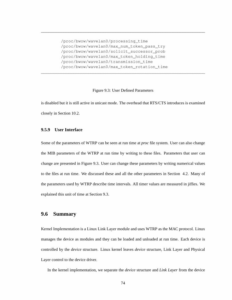
__________________________________________________________________
/proc/bwow/wavelan0/processing_time/proc/bwow/wavelan0/max_num_token_pass_try/proc/bwow/wavelan0/solicit_successor_prob/proc/bwow/wavelan0/max_token_holding_time/proc/bwow/wavelan0/transmission_time/proc/bwow/wavelan0/max_token_rotation_time
__________________________________________________________________
Figure 9.3: User Defined Parameters
is disabled but it is still active in unicast mode. The overhead that RTS/CTS introduces is examined
closely in Section 10.2.
9.5.9 User Interface
Some of the parameters of WTRP can be seen at run time atprocfile system. User can also change
the MIB parameters of the WTRP at run time by writing to these files. Parameters that user can
change are presented in Figure 9.3. User can change these parameters by writing numerical values
to the files at run time. We discussed these and all the other parameters in Section 4.2. Many of
the parameters used by WTRP describe time intervals. All timer values are measured in jiffies. We
explained this unit of time at Section 9.3.
9.6 Summary
Kernel Implementation is a Linux Link Layer module and uses WTRP as the MAC protocol. Linux
manages the device as modules and they can be loaded and unloaded at run time. Each device is
controlled by thedevicestructure. Linux kernel leavesdevicestructure, Link Layer and Physical
Layer control to the device driver.
In the kernel implementation, we separate thedevicestructure andLink Layerfrom the device
74

driver and WTRP module is implemented into Link Layer as the MAC protocol. ABWOW Glue
Layeris introduced that encapsulates thedevicestructure. Data coming from and going to the device
driver first comes to the BWOW Glue layer and is directed to the WTRP module. WTRP module
then controls the usage of medium by the station.
Kernel implementation creates logs for the station parameters in theproc file system. Each
parameter is represented by a file and MIB parameters can be changed at run time by writing into
them.
75
Chapter 10
Analysis
10.1 Proof of Stability
10.1.1 Introduction
We will prove that when transmission losses and topological changes of the graph stop at timet,
and stations do not go into theofflinestate voluntarily, then the algorithm will come to a stable state
where all stations cluster into rings at sometimes > t. The following is a brief outline of the proof.
We first prove that interference is cancelled; after the creation of the first ring only that ring is
allowed to transmit and all equivalent tokens are deleted by multiple token resolution protocol in
finite time. Then, we show that the ring becomes stable in a finite time and finally, we prove that
in one ring the bijection that represents correct relationship between predecessor and successor (see
definitions under Section 10.1.3 for the exact definition) increases monotonically to the maximum
number of nodes in the graph in finite time. When all bijections converge, we say that all rings,
operating in different channels, are correct.
76
10.1.2 Model
Constants
1. MTRT: Maximum Token Rotation Time. (Defined more precisely in lemma 10.1.6)
2. M: set of all MAC addresses
3. IDLE TIME: the amount of time that a station waits for token in a ring. IDLETIME≥MTRT
4. CLAIM TOKEN TIME: the amount of time that a station waits before regenerating a token
when the medium is quiescent. CLAIMTOKEN TIME≥IDLE TIME
5. INRING TIME: the amount of time that a station waits when the station is not receiving any
acceptable token, before going into theofflinestate. INRINGTIME≥IDLE TIME≥MTRT,
INRING TIME < 2 IDLE TIME
6. MAX NoN: maximum number of nodes that is allowed in a ring.
10.1.3 Graph
1. Definitions
(a) The adjacency graph,G(t), is defined by a set of undirected edges,E(t), and a set of
stations,V (t), at timet.
(b) A station represents a data-link layer of a communication station.
(c) The set of edges,E(t), corresponds to the set of transmission links between stations.
e(x, y)∈E(t), if and only if x is in the transmission range ofy, x is in the reception
range ofy, y is in the transmission range ofx, andy is in the reception range ofx; we
sayx andy are connected.
(d) |E(t)| - the number of the edges in the graph at timet.
77
(e) |V (t)| - the number of the stations in the graph at timet.
2. Assumptions
(a) If stationx is in transmission range of stationy, theny is also in the transmission range
of x.
(b) If stationx is in reception range of stationy, theny is also in the reception range ofx.
(c) No station hears corrupted messages (The physical layer filters out all corrupted mes-
sages.)
Token
1. Attributes
p.type ∈ {setpredecessor,setsuccessor,token,solicitsuccessor}
p.ra ∈ M //ring address of the token
p.sa ∈ M //source address of the token
p.da ∈ M //destination address of the token
p.seq ∈ Z //sequence number of the token
p.genseq ∈ Z //generation sequence number of the token
p.non ∈ Z //number of nodes in the ring of token
2. Definitions
(a) ri(t) = a set of nodes in ringi.
(b) ti(t) = a set of tokens inri(t).
(c) Tokenx and tokeny are said to be equivalent when their ring addresses are the same.
78

(d) The priority of the token is as follows: Tokenx is said to have higher priority thany if
its generation sequence number is higher thany. Given thatx has the same generation
sequence number asy, x has higher priority if it has the higher ring address.
(e) In this proof, we often refer to the same token in the future. This is not a cause for con-
fusion since a token does not split into multiple tokens as suggested by our assumption
of no transmission error.
Station
1. Attributes
x.genseq(t)∈Z // the generation sequence number of the last token thatx accepted.
x.ra(t) ∈M// ring address ofx
x.TS ∈M// the MAC address ofx
x.NS(t) ∈M// the MAC address of the station to whichx forwards tokens.
x.PS(t) ∈M// the MAC address of the station from whichx accepts tokens.
x.non ∈Z // the number of nodes in the ring of station.
2. Definitions
(a) x is said to be the owner of tokenp if x.TS =p.RA.
(b) The priority of a station is the priority of the token that the station last accepted.
3. Assumptions
(a) The MAC address is unique to each station.x.TS6=y.TS if x 6=y
79
10.1.4 Network
1. Definitions
(a) NetworkN(t) is defined by a set of directed edgesL(t) and a set of verticesV (t), at
time t.
(b) For stationx andy, an edgeps(x, y) exists if and only ifx.PS =y, and an edgens(x.y)
exists if and only ifx.NS =y.
(c) Set L(t) corresponds to the set ofPS and NS mapping between stations.L(t) =
{ps(x, y), ns(x, y) | for all x in V (t)}
(d) For stations x and y, if x.NS = y, y.PS = x, and if y can receive and accepts NORMAL
tokens from x then, we say that x has the bijection with y.
(e) S = {< x.y > | x has the bijection withy}
(f) A set of stations,ri(t), is called a ring if for all x∈ri(t), x has the bijection with its
successor,y.
10.1.5 Proof
Assumptions
1. No transmission error occurs aftert. (All transmissions are successful.)
2. GraphG(t) remains constant aftert.
3. Stations do not voluntarily go into theofflinestate.
Out-Ring Interference Cancellation
Lemma 10.1.1 When a station hears a transmission from another ring, it suspends its transmission.
80
If a station hears a transmission from another ring, it goes tofloatingor offlinestate when it is in a
self-ring or normal ring respectively by the implementation.
Lemma 10.1.2 At timek ≤ CLAIM TOKENTIME, a station detects a ring.
For a station, it takes maximum one MTRT to hear a transmission, if there is a ring in the medium.
If there is no ring, it takes maximum one CLAIMTOKEN TIME to hear a transmission since one
of the stations needs to create a self-ring and transmit the token.
Lemma 10.1.3 If there exists a ring operating in a channel, interference at that channel from the
stations out of the ring is eliminated within a CLAIMTOKENTIME.
From lemma 10.1.1 and 10.1.2, we know that a station detects a ring in a finite time and we know
that when a station detects a ring, it suspends its transmission. As a result, only the ring operating it
that channel is allowed to transmit.
In-Ring Interference Cancellation
Lemma 10.1.4 While a station is not in theoffline state, the priority of the station increases with
time.
A station does not accept a token from another station with a equal or lower priority than that
of itself, by the implementation. Also, when a station generates a token upon expiration of the
IDLE TIMER, the station increases its priority by increasing the generation sequence number by 2.
Lemma 10.1.5 Choose any tokenp at timet = t0, and build an ordered list of paths taken byp,
say< (x0, t0), (x1, t1), (x2, t2), ..., (xm, tm) >, wheretn is the time that tokenp visits the station
xn, and ti + 1 > ti. If there exists a stationxi = xj in the pair list such that 0≤i < j≤m and
tj − ti < MTRT , then there must be ak such that i≤k≤j, andxk ownsp.
81

Assume by contradiction that we findxi = xj such that 0≤i,j≤m andtj − ti < MTRT, but we
cannot find the owner of tokenp, xk, such that i≤k≤j. This means that the generation sequence
numbers of the token when it arrives atxi and the generation sequence number when it arrives atxj
is the same, because no station other than the owner of the token modifies the generation sequence
number.
Also, xj could not have been in theofflinestate at any time afterti, becausexi could not have
been able to rejoin another ring after exiting a ring for one MTRT (or more precisely, exiting of
theofflinestate for one MTRT), by the implementation. Because a station is not allowed to receive
a token when it is in theoffline state, it could not have receivedp before timeti + MTRT. Thus,
xi could not have been in theofflinestate since timeti. Because of lemma 10.1.4, the priority of
a station can only increase while it is not in theofflinestate and thus, it does not make sense that
tokenp could have survived stationxj .
Lemma 10.1.6 Tokenp must have visited a station twice if it survives until timet + MTRT.
We define MTRT to be the maximum time it takes for a token to visit a station twice if it survives,
under our assumption of no transmission errors and no topological change. This cannot be longer
than the amount of time for all stations to transmit, because the token must run out of stations that
it can visit and choose among one of the stations that it has already visited to visit.
Lemma 10.1.7 If no multiple equivalent tokens exist at timet, then no multiple equivalent tokens
exist at times > t.
Suppose that there exist multiple equivalent tokens at times when there were no multiple equivalent
tokens at timet, such thats > t. Because of our assumption, it is impossible for a station to generate
multiple equivalent tokens from transmission errors. Then a station must have generated a token
when a token that it has previously generated is still in the graph. But the IDLETIME is greater
82

than MTRT. And we know that a token dies when it doesn’t see its owner for MTRT. Thus the station
could not have generated the equivalent token when the token that it has previously generated is still
in the graph.
Lemma 10.1.8 No multiple equivalent tokens exist at timet + 2MTRT.
All surviving equivalent tokens will go though the owner of the token in one MTRT as shown in
10.1.6. After one MTRT, the owner will remember the highest priority token among them. Within
the next MTRT, all or all but one equivalent token will be deleted, because the owner will not pass
any token that has a lower priority than the highest priority token that it received.
If the owner of the token leaves the ring at any time, all tokens will be deleted since the owner
is not able to come back to a ring in less than one MTRT.
Lemma 10.1.9 There exist a times, such thats < t + MTRT and no multiple equivalent tokens
exist any timeu > s.
This directly follows from 10.1.7 and 10.1.8. From 10.1.8, we know that no multiple equivalent
tokens exist at timet + MTRT. This means all multiple equivalent tokens must have been removed
at times beforet + MTRT. From 10.1.7, no multiple equivalent tokens exist atu > s.
Lemma 10.1.10At times > t, then withins + IDLE TIME + 3MTRT, there exists one and only
one token in any ring.
There could be multiple tokens in a ring at times. Either one and only one of these tokens will
survive or none will survive by times + 2MTRT. Stationy in a ring will only accept a token if it
has higher priority than the last token that it accepted. This means that after one revolution, the
priority of all existing tokens must be increasing in terms of its order of visits to stationy. All of
these tokens must visit stationy within another MTRT, and will be deleted but one token.
83
Even if all tokens get deleted at timeu > s, within u + IDLE TIME, there exists at least one
token in the ring. From the bijection, we know that ifx has the bijection withy, y must accept
tokens fromx. This means that the station that holds the token has the higher priority than its
successor. The only station that is an exception to this rule is the owner of the token, because
the owner increments the generation sequence number by one when it passes the token. The only
generation sequence number assignment that will satisfy these constraints is the following. The
generation sequence number of the stations from the successor of the owner to the station with the
token has the same generation sequence number as the token. The generation sequence number
from the successor of the station with the token to the owner is one less than that of the token. This
means that when one or more stations regenerate token during [u, u + IDLE TIME], the generation
sequence number of these tokens will be higher than that of any stations at times. Because these
tokens will be passed around as a NORMAL token, only the highest priority token will survive
within one MTRT, and lower priority tokens will be deleted.
Stability
Lemma 10.1.11A ring will not break after timet + 2MTRT+INRINGTIME, and the number of
stations in the ring will not decrease.
A station updates itsNS pointer when it is unable to pass the token to its successor, leaves the
ring, or receivesset successor. Because each station in a ring has the bijections with its successor,
it does not make sense that it is unable to pass the token to its successor. Thus, no station will
be kicked out of the ring. Also, according to our assumption, a station will not leave the ring
voluntarily. When a station receives theset successor, theNSpointer of the station will change.
However, the ring will still not break since all contending stations must have a connection with the
successor of the soliciting station, according to our assumption.
84
A station updates itsPSpointer when it accepts a token from a station different from its pre-
decessor. A station may accept thesetpredecessortoken from another station, if the station has
the same ring address, causing the ring to break. This situation cannot possibly arise. A station
in the ring could not possibly have received a token from a station in the same ring that is not its
predecessor since each station in the ring has a bijection with its successor and could not have failed
to pass a token to its successor. Moreover, from our assumption, a station is not allowed to leave the
ring voluntarily and induce its predecessor to generatesetpredecessor.
Now we will show aftert + MTRT+ INRING TIME, a station outside a ring cannot possibly
send asetpredecessortoken to a station inside the ring with the same ring address. Let us suppose
that stationy, with the ring addressB, receives a token from stationw, outside of the ring. Let us
label the predecessor of stationy asx. From timet + MTRT on, no more multiple equivalent tokens
exist according to lemma 10.1.9. A station cannot possibly remember a token that did not exist
at timet + MTRT, and at timet + MTRT + INRING TIME, because a station must have accepted
a token during [t + MTRT, t + MTRT + INRING TIME] or have formed aself-ring. Thus, byt
+ MTRT + INRING TIME, if a station remembers anything about the token with a particular ring
address,B, it is remembering the same token. If a station receives a token from a station outside the
ring, then the token must have made a loop from stationy to w and back toy. This means that there
was a breach in the ring thatx andy belongs to, because when a token travels it makes bijection
between the sender and the acceptor of the token. For stationx andy to be in the same ring at time
t + MTRT + INRING TIME, a new token must have been regenerated by a station in the loop after
the token with ring addressB has passed them by. But this does not make sense becausey must
have received the token with the ring addressB within MTRT since the last time it saw it, and all
stations in the loop have seen the token after stationy accepted it.
85
Ring Enlargement
Lemma 10.1.12 If stationx has the bijection with its successory, then the INRINGTIMER ofx
goes off beforey.
The fact thatx has the bijection withy shows that the last tokeny accepted was fromx. Thenx
must have reset its INRINGTIMER beforey had. Thus, INRINGTIMER of y cannot go off before
x.
Lemma 10.1.13When a station goes out of ring (into theoffline state), |S|, the number of the
bijections, remains positive.
Let us say the predecessor ofy is x, and the successor ofy is z. When stationy goes into theoffline
state, it waits for a invitation without changing its channel and changes when it detects a token
p.non=MAX NoN.
We distinguish the two cases where a station can be kicked out. The first case is when the
INRING TIMER expires (Section 4.3). In this case, from the lemma 10.1.8,x could not have the
bijection withy, because if it did, the INRINGTIMER of x would have gone off beforey. In this
case, regardless of whethery had bijection withz or not,|S| will not decrease, because in the worst
cases|S| stays the same ify had the bijection withz. The second case is wheny is kicked out
because it is not successful in finding a successor. Again regardless of whetherx had the bijection
with y or not,|S| will remain positive, because in the worst case we lose the bijection fromx to y,
butx creates a bijection with another node or a self-bijection.
Lemma 10.1.14When the number of bijections is positive, after a station accepts a token some
time after t,|S|, the number of the bijections, monotonic increases.
After accepting a token, stationy either goes into theofflinestate, or attempts to pass the token to
its successor, or sends thesolicit successortoken. |S| is non-decreasing in the first case since the
86
station does not go voluntarily into theofflinestate according to our assumption. So we are left to
prove that|S| is non-decreasing in the last two cases where stationy attempts to pass the token to
its successor, or sends thesolicit successortoken.
Let us see what happens ify decides to pass the token to its successor,z. If y has the bijection
with z, then it will pass the token successfully and there will be no change in the network. In the
case thaty does not have the bijection withz, y will try to find a station to form the bijection with.
If y is not successful within a certain window of time, it will go into theoffline state. And we
have already shown in the lemma 10.1.13, that|S| remains positive. Now Let us consider the case
wherey successfully finds a station to form the bijection with.U is the station thaty finally forms
the bijection with. W is the predecessor ofu, beforey became its predecessor. Suppose w had
the bijection with u, beforey came along. Then|S| is the same as before because we gained one
bijection fromx to u, but lost one fromw andu. If there was no bijection fromw to u to begin
with, then, we would have gained on|S| by one.
Now Let us see what happens ify decides to sends asolicit successortoken. If no station wins
the contention, theny will proceed to pass the token to its successor. And we have already shown in
the previous paragraph that|S| does not decrease. If stationz wins the contention and successfully
sends theset successortoken, theny now has the bijection withz. Stationz inherits the generation
sequence number, the ring address, and thePS pointer fromy, allowing successful establishment
of the bijection withw the successor ofy. If y did not have the bijection withw, then |S| will
likely stay the same. With any luck,|S| will actually increase by one ifw andz has the same ring
address andw does not have a higher priority thanz. Otherwise, the result will be the same as the
case where a station tries to pass a token to a successor that it does not have the bijection with, as
discussed in the previous paragraph.
Lemma 10.1.15 |S| monotonically increases and will converge to|V | in a finite time.
87

From lemma 10.1.13 and lemma 10.1.14, we have proven that|S| is non-decreasing. We have
also shown in lemma 10.1.11 that a ring will not break nor decrease in size after timet + MTRT
+ INRING TIME. In addition a station will not solicit another station to join unless it sees two
successful token rotations. If there is no topological change, a station will not join a node unless it
is part of a ring. This means that the number of stations in a ring does not decrease.
If |S| 6= |V | at some time s such thats > t + 2MTRT + INRING TIME, there exists a stationy
that is waiting to join at timet. Stationy waits to join until it hears a token thatp.non=MAX NoN,
then it changes the channel. In this case, we gained a full ring in one channel and start to create
another ring in another channel. From lemma 10.1.3, the stations operating in the other channel de-
tects a ring in one CLAIMTOKEN TIME. If the stationy accepts a token, allowing another station
to form the bijection withy, then we gain in the size of|S|. Since within every INRINGTIME, the
number of bijection that belongs to a ring, or the number of bijections increase,|S| will converge
to |V | in finite time. When|S| finally converges to|V | at timeu > s, using the multiple token
resolution lemma 10.1.14, we know that there exists one and only one token in all rings.
10.1.6 Conclusion
For this proof to be applicable, the assumptions must be reasonable. The assumption of this proof
was that after a certain timet, transmission errors and the topological changes stop. One of the
things that we can hope for when using this kind of assumption is that the algorithm reaches the
correct state fast enough when the assumption holds. However, we found that the protocol, in the
worst case, can take time in the order of magnitude of MTRT. One can argue for the first assumption
of fixed topology by supposing that the rate topology changes will probably be slow compared to
the rate of transmission. The assumption that there will be no transmission errors for the duration
in magnitude of MTRT may be valid when considering the fact that wireless link is a type of trans-
88
mission error-free. This is especially true when there are multiple tokens in the ring, or when there
are multiple rings that run on the different channels.
According to this proof, the IDLETIME can be very large if we are unable to effectively put a
bound on MTRT, because we have a constraint — IDLETIME > MTRT. A large IDLE TIME can
significantly degrade the performance of the network because there will be a long duration before
the network regenerates the token in case of loss of token. One way to get around this is to put an
upper bound on the number of stations that can be in the graph. One solution we adopted based on
this idea is maximum number of nodes and ordered list of channel assignments with the distributed
channel assignment protocol where a station shift to next channel when it detects a full ring.
10.2 Saturation Throughput Analysis
10.2.1 Introduction
In this section, we concentrate on the analytical evaluation of the WTRP with the assumption of
ideal channel conditions and finite number of non-mobile terminals, and all terminals belonging to
a single ring. We propose an extremely simple Markov chain model that allows to compute the
saturation throughput performance of WTRP. The key approximation that enables our model is the
assumption of formed-ring, which means that every node in the medium belongs to a single ring
and WTRP works in saturation operating conditions. We followed the approach that is presented in
[11], [14] for saturation throughput analysis for IEEE 802.11.
10.2.2 Model
We present the analytical evaluation of the “Saturation Throughput”. This performance figure is
defined as the limit reached by the system throughput as the offered load increases, and represents
the maximum load that the system can carry in stable conditions [11]. In the analysis, we operate in
89
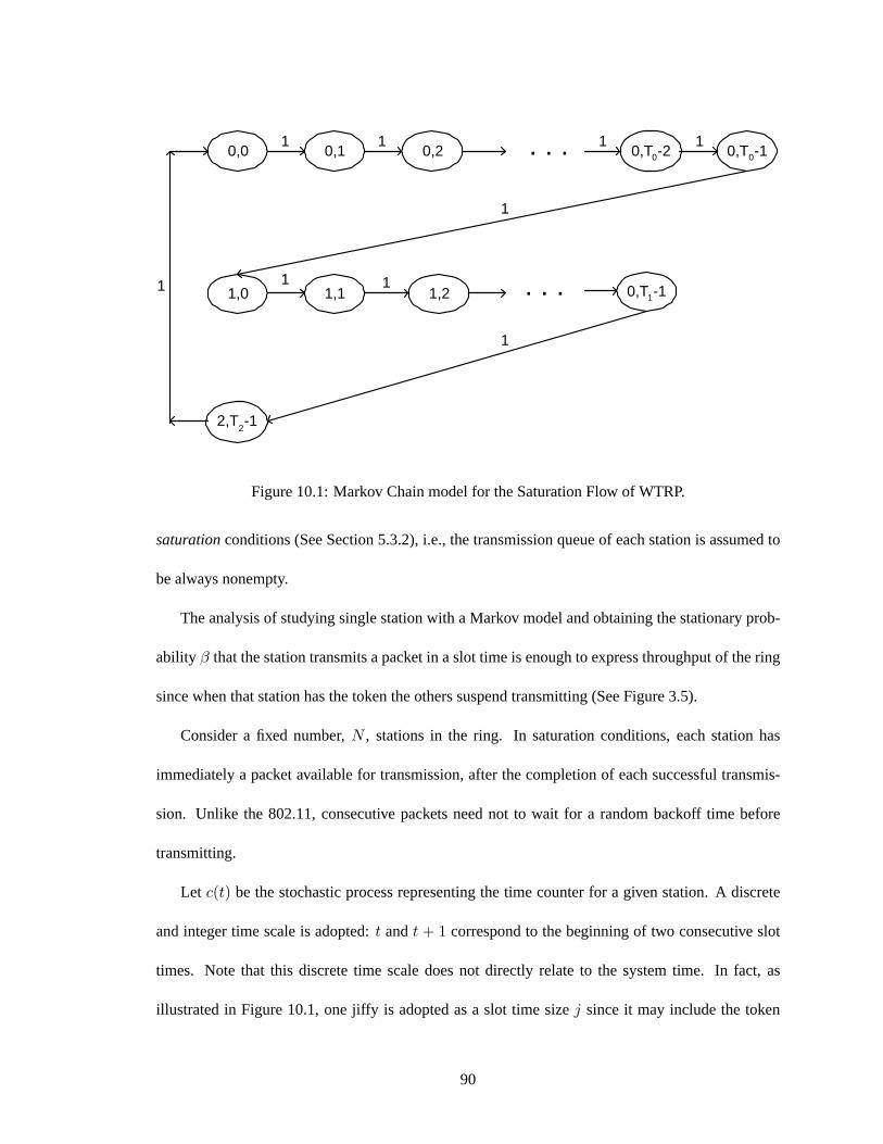
0,0
1,0
0,T 0 -1 0,T 0 -2 0,2 0,1
2,T 2 -1
0,T 1 -1 1,2 1,1
. . .
. . .
1
1
1
1 1
1 1
1
1
Figure 10.1: Markov Chain model for the Saturation Flow of WTRP.
saturationconditions (See Section 5.3.2), i.e., the transmission queue of each station is assumed to
be always nonempty.
The analysis of studying single station with a Markov model and obtaining the stationary prob-
ability β that the station transmits a packet in a slot time is enough to express throughput of the ring
since when that station has the token the others suspend transmitting (See Figure 3.5).
Consider a fixed number,N , stations in the ring. In saturation conditions, each station has
immediately a packet available for transmission, after the completion of each successful transmis-
sion. Unlike the 802.11, consecutive packets need not to wait for a random backoff time before
transmitting.
Let c(t) be the stochastic process representing the time counter for a given station. A discrete
and integer time scale is adopted:t andt + 1 correspond to the beginning of two consecutive slot
times. Note that this discrete time scale does not directly relate to the system time. In fact, as
illustrated in Figure 10.1, one jiffy is adopted as a slot time sizej since it may include the token
90

transmission. Since the value of the token rotation time of the ring depends also on token holding
time and token passing time, for convenience letI, R, H be “Idle Time”, “Maximum Token Rotation
Time”, “Token Holding Time” respectively such thatT0 = I = R − H − 1, T1 = H, T2 = 1.
Token passing time is taken as one slot time. We adopt the notation wherei ∈ (0, 2) is called “state”
asidle state ,havetokenstate andmonitoringstate respectively. Lets(t) be the stochastic process
representing the state(0, 1, 2) of the station at timet.
The key approximation in our model is that there is no station outside the ring and only one
ring. It is intuitive that this assumption results in more accurate results as long as there is no station
waiting to join or leave the ring and as a result, the possible interference from a station is eliminated.
It is possible to model the two-dimensional processs(t), c(t) with the discrete-time Markov
chain depicted in Figure 10.1. In this Markov chain, the only non-null one-step transition probabil-
ities are
P{i, k|i, k − 1} = 1, k ∈ (0, Ti)
P{i, 0|i− 1, k} = 1, k = Ti
P{0, 0|2, 0} = 1
(10.1)
The first equation in (10.1) accounts for the fact that, at the beginning of each slot time, the time
counter is incremented. In particular, as considered in the second and third equation of (10.1), when
timer expires, the protocol changes its state.
Let bi,k = limt→∞P{s(t) = i, c(t) = k}, i ∈ (0, 2), k ∈ (0, Ti) be the stationary distribution
of the chain. We now show that it is easy to obtain the closed form solution for this Markov chain.
First note that at
bi−1,0 = bi,0 = b0,0 i ∈ (0, 2) (10.2)
91

Owing to the chain regularities, for eachk ∈ (0, Ti),it is
bi,k =1
(I + H + 1)i ∈ (0, 2), k ∈ (0, Ti − 1) (10.3)
Thus, by relation (10.2), all the valuesbi,k are expressed as functions of the valueb0,0 which is
b0,0 =1M
(10.4)
We can now express the probabilityβ that a station transmits data in a randomly chosen slot
time. As any transmission occurs when thes(t) = 1, regardless of the counter.
β =H∑
k=1
b1,k = H × b0,0 =H
M(10.5)
However, in general,β depends on the packet size which sometimes affects unused slots in its
have token state because the remaining time is not enough to send a new packet. The assumption
we adopt is that packet transmission time is a multiple of the token holding time,H. And β prob-
ability only involved in fraction of time that the station is transmitting data bits. The packet firing
probability is the probability that the station is in state(1, k) k ∈ (0,K) whereK is the number of
packets that can be transmitted in one token holding time.
10.2.3 Throughput
Let S be the normalized system throughput, defined as the fraction of time the channel is used to
the number of successfully transmitted payload bits. To computeS, let us analyze what can happen
in a randomly chosen slot time. LetPtr be the probability that there is at least one transmission in
the considered slot time. SinceN stations are in the ring, and only one station has right to transmit,
the station transmits data with probability
92
Ptr =β
β + 1M
(10.6)
Let Pf is the probability that station starts firing a packet in the chosen slot time.
Pf =KM
β + 1M
(10.7)
The probabilityPs that a transmission occurring on the channel is successful is given by the
probability that exactly one station transmits on the channel, conditioned on the fact that at least one
station transmits, i.e.,
Ps = 1 (10.8)
We are now able to expressS as the ratio
S =E[payload information transmitted when holding the token]
E[length of time](10.9)
SinceE[P ] is the average packet payload size, the average amount of payload information
successfully transmitted in a slot time isPfPsE[P ], since a successful transmission occurs in a slot
time with probabilityPfPs. The average length of a slot time is readily obtained considering that,
with probability1− Ptr, the slot time is for token transmission; with probabilityPfPs it contains a
successful transmission, and with probabilityPf (1−Ps) it contains a collision. Hence, (8) becomes
S =PsPfE[P ]
(1− Ptr)j + PfPsTs + Pf (1− Ps)Tc(10.10)
Here,Ts is the average time the channel is sensed busy because of a successful transmission,
andTc is the average time the channel is sensed busy by each station during a collision.j is the
93

PHY hdr
MAC hdr
PHY hdr
MAC hdr
PAYLOAD
PAYLOAD
ACK
T success (implementation)
T success (general)
SIFS DIFS RTS CTS
SIFS SIFS
Figure 10.2:Ts for implementation and general
duration of an empty slot time andK is the number of packets a station can transmit during a token
holding time.
Let us first consider a system completely that is managed via the basic access mechanism.
Let H = PHYadr + MAChdr be the packet header, andδ be the propagation delay. As shown
in Figure 10.2, in the implementation (since we implemented on top of 802.11 card and when
broadcasted WaveLAN card operates in basic access mode by disabling RTS/CTS mechanism) and
general WTRP case we obtain
T imps = RTS + SIFS + δ + CTS + δ + H + E[P ] + SIFS + δ + ACK + DIFS + δ
T gens = H + E[P ]
T impc = 0 = T gen
c
(10.11)
The values of the parameters used to obtain numerical results are summarized in Table I. The
system values are those specified for the frequency hopping spread spectrum (FHSS) PHY layer
[26]. The channel bit rate is assumed to be equal to 1 Mbits. This rate is lower than that of wireless
card we used for simulation. This is to compare our result with that of 802.11 presented in [11].
Packet payload size of 8184 bits is considered, which takes one token holding time and that means
94
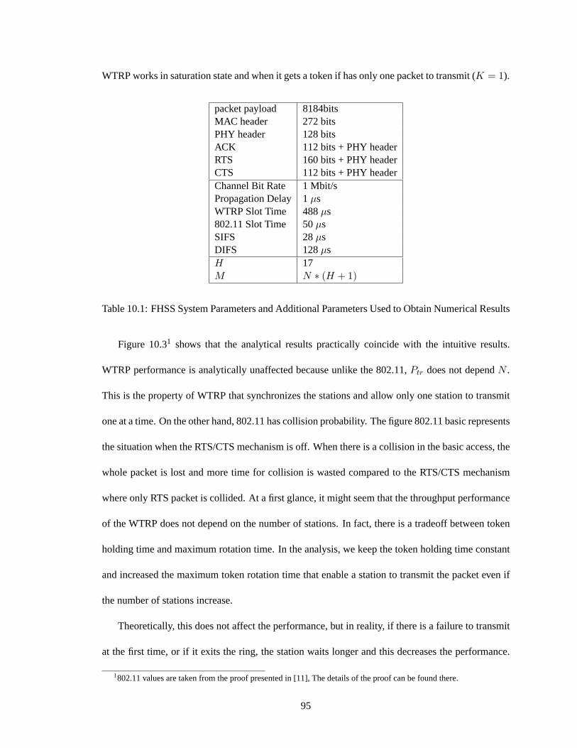
WTRP works in saturation state and when it gets a token if has only one packet to transmit (K = 1).
packet payload 8184bitsMAC header 272 bitsPHY header 128 bitsACK 112 bits + PHY headerRTS 160 bits + PHY headerCTS 112 bits + PHY headerChannel Bit Rate 1 Mbit/sPropagation Delay 1 µsWTRP Slot Time 488µs802.11 Slot Time 50µsSIFS 28µsDIFS 128µsH 17M N ∗ (H + 1)
Table 10.1: FHSS System Parameters and Additional Parameters Used to Obtain Numerical Results
Figure 10.31 shows that the analytical results practically coincide with the intuitive results.
WTRP performance is analytically unaffected because unlike the 802.11,Ptr does not dependN .
This is the property of WTRP that synchronizes the stations and allow only one station to transmit
one at a time. On the other hand, 802.11 has collision probability. The figure 802.11 basic represents
the situation when the RTS/CTS mechanism is off. When there is a collision in the basic access, the
whole packet is lost and more time for collision is wasted compared to the RTS/CTS mechanism
where only RTS packet is collided. At a first glance, it might seem that the throughput performance
of the WTRP does not depend on the number of stations. In fact, there is a tradeoff between token
holding time and maximum rotation time. In the analysis, we keep the token holding time constant
and increased the maximum token rotation time that enable a station to transmit the packet even if
the number of stations increase.
Theoretically, this does not affect the performance, but in reality, if there is a failure to transmit
at the first time, or if it exits the ring, the station waits longer and this decreases the performance.
1802.11 values are taken from the proof presented in [11], The details of the proof can be found there.
95

0 5 10 15 20 25 30 35 40 45 500.5
0.55
0.6
0.65
0.7
0.75
0.8
0.85
0.9
0.95
1
Number of Stations
Sat
urat
ion
Thr
ough
put
WTRP gen.WTRP imp.802.11 rts/cts802.11 basic
Figure 10.3: Saturation Throughput
96

On the other hand, if we keep the maximum token rotation time constant and decrease the token
holding time, the ring will be as responsive as before while number of stations increases but the
station capacity decreases because ratio of payload bits over transmitted bits will decrease.
10.2.4 Conclusion
We presented a simple analytical model to compute the saturation throughput performance of the
WTRP. Our model assumes a constant Token Holding Time even if the number of stations increases.
This results in a constant throughput for WTRP even as the number of stations increases in the
medium. The better performance is achieved because WTRP eliminates the collision probability by
sharing the slots among the stations and collision probability increases in IEEE 802.11 when the
number of active stations increases.
10.3 Summary
We proved that when transmission losses and topological changes of the graph stop at time t, and
stations do not go into theOFFLINE state voluntarily, then the algorithm will come to a stable state
in which all stations will belong to a ring at times > t. We also proved using a simple Markov
model that in a stable environment, when the station operates in thesaturationconditions, increase
in the network size does not degrade WTRP performance since spectrum usage is fixed and collision
probability is zero.
97
Chapter 11
Performance Analysis
11.1 Performance Analysis
We aim to show the effectiveness of WTRP in terms of “bound on latency”, where each station gets
right to transmit in a fixed time, “fairness”, where each station consumes equal amount of band-
width, “robustness”, where ring recovers from node failures without collapsing, “responsiveness”,
where ring responses fast enough to medium changes and “medium utilization” where ring utilize
the capacity of the channel at maximum. Performance of WTRP is analyzed for Constant Bit Rate
(CBR) and FTP traffic.
11.1.1 Scenario
The testbed is constructed by the laptop computers ( 2 Dell Inspiron 5000, 1 Dell Inspiron 8000,
6 Dell Latitude C600). Network structure is shown in Figure 11.1.Si , i ∈ (0, 7) use Lucent
WaveLAN Silver Cards (2Mbit/s), andL1, L2 have Lucent Orinoco Gold Cards(11 Mbit/s). In the
scenario,Si andLi are called “Sender” and “Listener” respectively. Listeners always use 802.11 as
the MAC protocol and senders use WTRP or 802.11. LetterN represent senders and one listener
98

S 1
S 3 S 7
S 5
S 6
S 8 S 2
S 4
L 1
L 2
Figure 11.1: Simulation Scenario
is assigned for each 3 sender. We choose this scenario in order to eliminate the overhead that is
introduced because of 802.11 protocol embedded to the WaveLAN card (See Section 9.5.8).
11.1.2 Optimum Operating Frequency
WTRP performs better in certain situations because of its deterministic property. We analyzed the
performance of WTRP under variable packet rate and packet size. For Figures 11.2 and 11.3, under
a constant packet size (100bytes) and we changed the packet generation rate. One can see from
Figures 11.2 and 11.3 that WTRP performs better than the 802.11 when the packet inter arrival time
is around MTRT. In the high loaded region where packet generating rate is less than MTRT, WTRP
shows fluctuations because of its fixed THT and packet queue size. In the scenario, THT only allows
a node to transmit one or two packets. This fills the buffer and consequently, stops the upper layer
99

101
102
104
105
Packet Inter Arrival Time (ms)
Thr
ough
put (
bps)
WTRP N=3 MTRT=30msWTRP N=3 MTRT=50ms802.11 N=3
WTRP/802.11 Ratio
30 500.5
1
1.5
Figure 11.2: Variable Packet Generating Rate - 3 Senders
101
102
105
Packet Inter Arrival Time (ms)
Thr
ough
put (
bps)
WTRP N=4 MTRT=50ms802.11 N=4
50
0.5
0.6
0.7
0.8
0.9
1
1.1
WTRP/802.11 Ratio
Figure 11.3: Variable Packet Generating Rate - 4 Senders
100
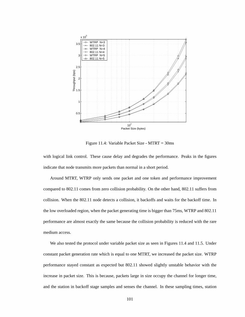
102
0.5
1
1.5
2
2.5
3
3.5
x 105
Packet Size (bytes)
Thr
ough
put (
bps)
WTRP N=3 802.11 N=3 WTRP N=4802.11 N=4WTRP N=5802.11 N=5
Figure 11.4: Variable Packet Size - MTRT = 30ms
with logical link control. These cause delay and degrades the performance. Peaks in the figures
indicate that node transmits more packets than normal in a short period.
Around MTRT, WTRP only sends one packet and one token and performance improvement
compared to 802.11 comes from zero collision probability. On the other hand, 802.11 suffers from
collision. When the 802.11 node detects a collision, it backoffs and waits for the backoff time. In
the low overloaded region, when the packet generating time is bigger than 75ms, WTRP and 802.11
performance are almost exactly the same because the collision probability is reduced with the rare
medium access.
We also tested the protocol under variable packet size as seen in Figures 11.4 and 11.5. Under
constant packet generation rate which is equal to one MTRT, we increased the packet size. WTRP
performance stayed constant as expected but 802.11 showed slightly unstable behavior with the
increase in packet size. This is because, packets large in size occupy the channel for longer time,
and the station in backoff stage samples and senses the channel. In these sampling times, station
101

102
0.5
1
1.5
2
2.5
x 105
Packet Size (bytes)
Thr
ough
put (
bps)
WTRP N=2 802.11 N=2 WTRP N=3802.11 N=3WTRP N=4802.11 N=4
Figure 11.5: Variable Packet Size - MTRT = 50ms
may have chance to detect empty channel even if the channel is not empty since packet inter arrival
time is longer than the sensing time.
11.1.3 Bound on Latency
From Figures 11.6 and 11.7, one can see that token rotation time distribution shows almost zero
variance when THT is set to 1.5ms. This means that every station gets chance to transmit in a
specific bounden time. Token rotation time increases less than one token holding time when a new
node is added and variance still remains close to zero that means that increase in network size does
not cause instability to WTRP.
Latency measurement can also be observed by examining the jitter of packet arrivals. Fig-
ure 11.8 shows the distribution of packet inter-arrivals of the listener when there are 3 senders. Each
sender sends 100bytes in every 50ms and MTRT is set to 50ms. Distribution shows that distribution
is dense at 50ms even if there is overhead of 802.11 Card in terms of introducing backoff interval.
102
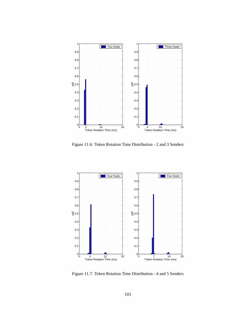
0 3 10 200
0.1
0.2
0.3
0.4
0.5
0.6
0.7
0.8
0.9
1
Token Rotation Time (ms)
Two Node
0 4 10 200
0.1
0.2
0.3
0.4
0.5
0.6
0.7
0.8
0.9
1
Token Rotation Time (ms)pd
f
Three Node
Figure 11.6: Token Rotation Time Distribution - 2 and 3 Senders
0 5 12 200
0.1
0.2
0.3
0.4
0.5
0.6
0.7
0.8
0.9
1
Token Rotation Time (ms)
Four Node
0 7 14 200
0.1
0.2
0.3
0.4
0.5
0.6
0.7
0.8
0.9
1
Token Rotation Time (ms)
Five Node
Figure 11.7: Token Rotation Time Distribution - 4 and 5 Senders
103
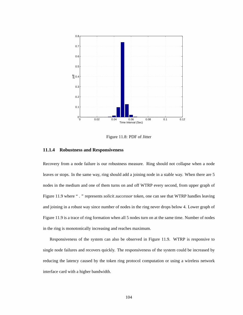
0 0.02 0.04 0.06 0.08 0.1 0.120
0.1
0.2
0.3
0.4
0.5
0.6
0.7
0.8
Time Interval (Sec)
Figure 11.8: PDF of Jitter
11.1.4 Robustness and Responsiveness
Recovery from a node failure is our robustness measure. Ring should not collapse when a node
leaves or stops. In the same way, ring should add a joining node in a stable way. When there are 5
nodes in the medium and one of them turns on and off WTRP every second, from upper graph of
Figure 11.9 where “ . ” representssolicit successortoken, one can see that WTRP handles leaving
and joining in a robust way since number of nodes in the ring never drops below 4. Lower graph of
Figure 11.9 is a trace of ring formation when all 5 nodes turn on at the same time. Number of nodes
in the ring is monotonically increasing and reaches maximum.
Responsiveness of the system can also be observed in Figure 11.9. WTRP is responsive to
single node failures and recovers quickly. The responsiveness of the system could be increased by
reducing the latency caused by the token ring protocol computation or using a wireless network
interface card with a higher bandwidth.
104
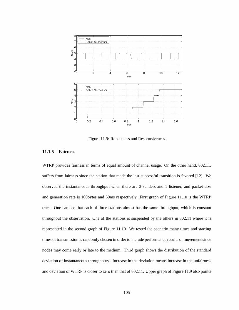
0 2 4 6 8 10 122
3
4
5
6
7
8
sec
NoN
NoNSolicit Successor
0 0.2 0.4 0.6 0.8 1 1.2 1.4 1.60
1
2
3
4
5
6
sec
NoN
NoNSolicit Successor
Figure 11.9: Robustness and Responsiveness
11.1.5 Fairness
WTRP provides fairness in terms of equal amount of channel usage. On the other hand, 802.11,
suffers from fairness since the station that made the last successful transition is favored [12]. We
observed the instantaneous throughput when there are 3 senders and 1 listener, and packet size
and generation rate is 100bytes and 50ms respectively. First graph of Figure 11.10 is the WTRP
trace. One can see that each of three stations almost has the same throughput, which is constant
throughout the observation. One of the stations is suspended by the others in 802.11 where it is
represented in the second graph of Figure 11.10. We tested the scenario many times and starting
times of transmission is randomly chosen in order to include performance results of movement since
nodes may come early or late to the medium. Third graph shows the distribution of the standard
deviation of instantaneous throughputs . Increase in the deviation means increase in the unfairness
and deviation of WTRP is closer to zero than that of 802.11. Upper graph of Figure 11.9 also points
105

200 400 600 800 1000 1200 14001.3
1.35
1.4
1.45
1.5
1.55
1.6x 10
4
Packet Number
Inst
anta
neou
s T
hrou
ghpu
t (bp
s)
WTRP
Node aNode bNode c
200 400 600 800 1000 1200 14001.3
1.35
1.4
1.45
1.5
1.55
1.6x 10
4
Packet Number
Inst
anta
neou
s T
hrou
ghpu
t (bp
s)802.11
Node aNode bNode c
0 50 100 150 200 250 300 350 400 450 5000
0.1
0.2
0.3
0.4
0.5
(bps)
Pdf of Standard Deviation of Instantaneous Throughputs
WTRP802.11
Figure 11.10: Instantaneous Throughput
to the fairness behavior of WTRP since even if a station comes late, station gets immediate right to
transmit when it belongs to the ring.
11.1.6 Network Size
In a wireless network without proper organization, each node causes an increase in collision proba-
bility. As a result, network size matters to protocols that suffer from collision such as 802.11. We
increase the number of nodes in the network and each node sends 100bytes with 50ms packet gen-
eration rate. As it can be inferred from the Figure 11.11, WTRP performs better than 802.11 and the
performance difference increases as the network grows in size. We expect higher difference, when
the WTRP is implemented on top of a card that does not use 802.11 protocol. Test is also performed
with Poisson packet generation rate when the parameter is 50ms. Results show that throughput is
higher in WTRP than 802.11 but difference of their performance varies. Since Poisson behavior
106
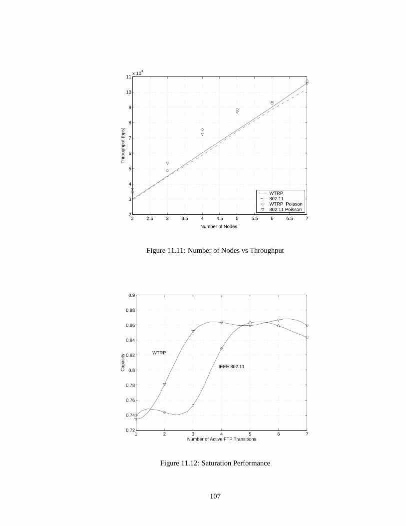
2 2.5 3 3.5 4 4.5 5 5.5 6 6.5 72
3
4
5
6
7
8
9
10
11x 10
4
Number of Nodes
Thr
ough
put (
bps)
WTRP802.11WTRP Poisson802.11 Poisson
Figure 11.11: Number of Nodes vs Throughput
1 2 3 4 5 6 70.72
0.74
0.76
0.78
0.8
0.82
0.84
0.86
0.88
0.9
Number of Active FTP Transitions
Cap
acity
WTRP
IEEE 802.11
Figure 11.12: Saturation Performance
107
does not affect WTRP but affects 802.11 positively or negatively.
Under heavy load, the token ring implementation performs better than IEEE 802.11. This is
shown in Figure 11.12. In the figure, the aggregate FTP bandwidth is plotted against the number of
simultaneous FTP transfers. Both cases involved number of nodes equal to the number of simulta-
neous FTP transfers. The FTP was done as follows. For the case of two simultaneous transfers, one
transfer goes from station 1 to station 2 and the other from station 2 to station 1. For the case of
three simultaneous transfers, the transfers are from 1 to 2, from 2 to 3, and from 3 to 1.
In Figure 11.8, we observed a decrease following a increase in IEEE802.11. The decrease in the
throughput is expected since the number of collisions increases in a CSMA medium access control
and after the saturation point, performance of IEEE802.11 degrades [14].
The performance intuitively should be constant in Wireless Token Ring case but improves in
the simulation when going from 1 to 3 simultaneous transfers. This can be explained as follows.
Since for all trials in Figure 11.8, theMaximum Token Rotation Timevaries, the nodes can not
operate at saturation point with few nodes in the network. As a result, the nodes can not use all of
the capacity. The need for retransmission of the data due to collisions is eliminated since WTRP
reduces collisions.
11.2 Summary
WTRP in its current implementation is disadvantaged relative to the original 802.11 driver because
WTRP is implemented on top of 802.11 in DCF mode, incurring all the overhead that is associated
with 802.11 plus the overhead from the WTRP. The overhead is the increased computation time and
packet header size.
We observe that WTRP has optimum operating condition when the packet generation rate is
equal to the token rotation time and as long as token holding time is enough , increase in packet size
108

does not affect its performance. WTRP responses in a quick and robust way to the possible results
of mobility. We find that WTRP achieves bounded delay and distributes bandwidth fairly among the
stations compared to 802.11. Finally, since collision is affectively reduced, WTRP is not affected
from the network size as long as each station use their THT at maximum.
109

Chapter 12
System Extensions
12.1 Introduction
WTRP is a new research topic and can be extended in various ways. In this chapter, we introduce
possible extensions to the WTRP and cite design issues left open.
12.2 Hybrid Schemes
Hybrid Schemes (See Figure 12.1) are the schemes where the centralized approach that uses the star
topology and the distributed approach that uses the ring topology are hierarchically mixed together.
All slave nodes need to have a connection with the master and master nodes are connected to each
other via WTRP. Packets are routed one-hop to the master with centralized protocol, multi-hop
with WTRP to the master of the destination and finally, one-hop to the destination with centralized
protocol.
110
12.3 Token Chain
Token chain (See Figure 12.1) creates the ring by bi-directional token passing. Token coming from
the predecessor is passed to the successor and token coming from the successor is passed to the
predecessor. The nodes at the edges have the same station as the predecessor and the successor.
A station gets right to transmit twice in one token rotation and consumes fixed amount of time in
total. In these structure, it is advantageous to communicate with only one node for the joining node
to become a ring member. However this is disadvantageous for the ring since permission to send
invitation belongs to the edge nodes now. The joining advantage leads to a ring that can be formed
in a wide area. These kind of network structures is suitable where the node distribution among the
area is rare.
12.4 Sensor Networks
Sensor networks is a special kind of network where the destination of all packets is the access
point to the backbone network. We can use token ring or token chain in sensor networks where low
performance is enough. All the nodes will belong to one ring and only one node will be transmitting
at a time. The energy consumption at the nodes can be decreased by putting nodes into sleep while
they do not have the token since the nodes predict their possible token reception time by considering
the number of nodes in the ring and token holding time of each node. Each node stores the data
packets coming from its predecessor and transmits all the packet to its successor. Access point may
also involve in multiple rings and may schedule giving right to transmit each ring by transmitting
the token in order.
111

Hybrid Scheme Token Chain
WTRP in Mobile IP Data Forwarding
Access Point
Figure 12.1: System Extensions
112

12.5 Data Forwarding
WTRP clusters stations into multiple rings. Different channels are assigned to different rings in
order to avoid interference. There are several possibilities for the routing scheme. We will introduce
one of them in which connected network can be created by “gateway” nodes that belong to two rings,
one of them is its own ring and the other is the ring that “gateway” nodes create, named “backbone
ring”. Routing is divided into intra-ring routing, routing between nodes that belong to the same ring
and inter-ring routing, routing between gateway nodes. Gateway node keeps the information of the
nodes. If the destination nodes belongs to another ring, packets are forwarded to the gateway node
and gateway node forwards it to its successor in the backbone ring (See Figure 12.1). When the
gateway node of the destination gets the packet, it sends them to the destination. Backbone ring can
also be formed with token chain.
12.6 Extension to Mobile IP
Mobile IP has been designed within the IETF to serve the needs of the increasing population of mo-
bile computer users who wish to connect to the Internet and maintain communications as they move
from place to place. WTRP provides efficient bandwidth share to the users and provides solutions
to the early detection of attachment points and movement detection of mobile node problems. Both
problems brings concerns in Mobile IP research in order to decrease hand-off time.
In the Mobile IP design with WTRP (See Figure 12.1), resource information can be injected to
the token signal. This token may also contain thecare of addressof the attachment point, which
enables the mobile node to detect the attachment point early without waiting for beacon signals. As
a result, the time that takes for a node to communicate with the base station is equal to the time to get
into the ring. When the mobile node lost the connectivity to the attachment point, attachment point
113

can easily detect the movement by checking its connectivity table and execute a smooth hand-off
algorithm. Papers show that hand-off time in Mobile IP is dominated by the beacon period of the
attachment points [17]. Designing Mobile IP with WTRP may eliminate the beacon necessity and
inject beacon information to the periodic token signal.
12.7 Multimedia
Nodes in a ring may access different kind of resources. Resources can range from printer to an
internet access. The resource information can be conveyed by injecting to the token. If a mobile
node requires a resource, it searches for a ring that has the appropriate resource. As an analogy,
WTRP and IEEE 802.11 can be thought as ”Guest enters the appropriate house by checking the
name tag on the door and finds the right house” and ”Guest enters the appropriate house by entering
each house and asking the person to the households” respectively.
12.8 Summary
We presented the possible extensions to the WTRP. WTRP idea is suitable for many wireless net-
works. Networks can leverage token passing identity to use as an information carrier and WTRP is
compatible to work in a hierarchy with other MAC layer protocols.
114
Chapter 13
Conclusion
WTRP is inspired from IEEE802.4 token bus protocol. The development of IEEE802.4 was initiated
by people from General Motors and other companies interested in factory automation [16][25].
Features such as bounded latency and robustness against multiple node failures are some of the
reasons for this choice. In addition to bringing the same bounded latency and robustness features to
the wireless medium, WTRP also manages ad hoc topologies.
We deployed the WTRP idea in three implementations: Simulator, User-Space and Kernel Im-
plementations. We created a sharable library and functions that enable the implementations use
the library. Simulator implementation is a simulation tool for WTRP and extendable to any other
network module. It provides interfaces to simulate the implementation code in large wireless net-
works. User-Space implementation is a platform independent implementation in application layer.
This implementation is useful under a controlled application environment when utilized on top of
an arbitrary network interface card. Kernel implementation is a Linux link layer module built on
top of the IEEE802.11 in DCF mode. It incurs all the overhead that is associated with IEEE802.11.
Despite the overhead, we have found that WTRP performs well or even better under heavy load.
We have designed a protocol that is fast in terms of recovery and efficient with zero collision
115

probability. The consistency of the token rotation time, regardless of the number of simultaneous
transmissions, is key to bounding the medium access latency. This perhaps is a valuable support for
real time applications, emergency management, and automated highway systems.
116
Bibliography
[1] Berkeley Web Over Wireless Group,http://wow.eecs.berkeley.edu.
[2] D. Lee,Wireless Token Ring Protocol, Master’s Thesus at Berkeley, 2001.
[3] D. Lee, B. Dundar, M. Ergen, A. Puri,Socket Interface for User Applications in WOW Project,
http://wow.eecs.berkeley.edu.
[4] International Standard ISO IEC8802-4:1990— ANSI/IEEE Std. 802.4-1990.
[5] K. Nichols, S. Blake, F. Baker, D. Black,RFC2474 Definition of the Differentiated Services
Field (DS Field) in the IPv4 and IPv6 Headers, December 1998.
[6] S. Herzog,RFC2750 RSVP Extensions for Policy Control, January 2000.
[7] Draft International Standard ISO IEC 8802-11— IEEE P802.11/D10, 14 January 1999.
[8] M. Hannikainen, J. Knuutila, A. Letonsaari, T. Hamalainen, J. Jokela, J. Ala-Laurila, J. Saari-
nen,TUTMAC: a medium access control protocol for a new multimedia wireless local area
network, Ninth IEEE International Symposium on Personal, Indoor and Mobile Radio Com-
munications, New York, NY, USA: IEEE, 1998. p.592-6 vol.2. 3 vol. 1574 pp.
117
[9] I. F. Akyildiz, J. McNair, C. L. Martorell, R. Puigjaner, Y. Yesha,Medium access control
protocols for multimedia traffic in wireless networks, IEEE Network, vol.13, (no.4), IEEE,
July-Aug. 1999. p.39-47.
[10] P. Varaiya,Smart Cars on Smart Roads: Problems of Control, IEEE Transactions on Automatic
Control, 38(2):195-207, February 1993.
[11] G. Bianchi, Performance Analysis of the IEEE 802.11 Distributed Coordination Function,
IEEE Journal on Selected Areas in Communications, Vol.18, No. 3, MARCH 2000.
[12] Y. Wang, Achieving Fairness in IEEE 802.11 DFWMAC with Variable Packet Size, Global
Telecommunications Conference, 2001.
[13] T. Pagtzis, P. Kirstein, S. Hailes,Operational and Fairness Issues with Connection-less Traffic
over IEEE802.11b, ICC 2001.
[14] G. Bianchi, IEEE 802.11-Saturation throughput analysis, IEEE Commun. Lett., vol. 2, pp.
318-320, Dec. 1998.
[15] H. Shim, T. J. Koo, F. Hoffman, S. Sastry,A Comprehensive Study on Control Design of
Autonomous Helicopter, In Proceedings of IEEE Conference on Decision and Control, Florida,
December 1998.
[16] A. Tanenbaum,Computer Networks, Prentice Hall, New Jersey, 1988.
[17] M. Ergen, S. Coleri, B. Dundar, A. Puri, P. Varaiya,Fast Handoff with GPS Routing in Mobile
IP, IPCN Paris April, 2002.
[18] High Performance Radio Local Area Network (HIPERLAN), Type 1; Functional specification,
ETS 300 652, Radio Equipment and systems (RES) October 1996.
118
[19] Bluetooth,http://www.bluetooth.com.
[20] Network Animator,http://www.isi.edu/nsnam/nam.
[21] Network Simulator,http://www.isi.edu/nsnam/ns.
[22] WaveLAN,http://www.wavelan.com.
[23] The Teja Technical Reference,http://www.teja.com.
[24] WaveLAN/IEEE PCMCIA device driver for Linux (WVLAN49), Lucent Technologies Inc,
1998-1999.
[25] W. McCoy,RFC1008: Implementation Guide for the ISO Transport Protocol, 1987.
[26] IEEE Standard for Wireless LAN Medium Access Control (MAC) and Physical Layer (PHY)
Specifications, Nov.1997. P802.11.
[27] Yankee Group,http://www.yankeegroup.com.
[28] ARS,http://www.ars1.com.
119


![[Pronto] Token Ring](https://static.fdocuments.in/doc/165x107/557212ca497959fc0b90f103/pronto-token-ring.jpg)