
WSM_0000407_2
76
© Scania CV AB 2005, Sweden 1 585 749 03:02-03 Issue 3 en EDC MS5 for injection pump Troubleshooting 118 669 EDC
-
Upload
truchon415 -
Category
Documents
-
view
43 -
download
5
Transcript of WSM_0000407_2

© Scania CV AB 2005, Sweden
1 585 74903:02-03
Issue 3 enEDC MS5 for injection pump
Troubleshooting
118
669
EDC
2
Contents
ContentsGeneral .................................................................................. 3
Faults that do not generate fault codes .................................................................................. 4
Fault codes Working procedure ................................................... 7How to read fault codes from the diagnostic lamp .......................................................................... 8How to erase fault codes......................................... 10List of fault codes ................................................... 11
Operational test Vehicles with control for cruise control.................. 47Vehicles without control for cruise control ............ 47
Component locations and wiring diagrams General ................................................................... 49
9-litre engine, bus ................................................... 509-litre engine, truck ................................................ 5612 litre engine ......................................................... 6214 litre engine ......................................................... 68
© Scania CV AB 2005, Sweden 03:02-03
General
Fuel system with injection pump and EDC MS5
GeneralThis booklet contains the following descriptions:
• Faults that do not generate fault codes.
• Fault codes how to present and erase them.
There is also a complete list of fault codes. The reason why fault codes are generated and how to rectify the fault is also described there. It is the same fault code list that is found in Scania Diagnos.
• An operational test. Perform the operational test after each repair.
At the end of the booklet you will find wiring diagrams and component location diagrams.
You will also find a table showing which component may be faulty when a specific fault code is recorded. The table also shows the current paths in the wiring diagrams on which you will find the respective components.
03:02-03 © Scania CV AB 2
005, Sweden 3
4
Faults that do not generate fault codes
Faults that do not generate fault codesThe table below contains descriptions of faults that can occur without generating fault codes.
Note: Remember that the fuel system is just like an ordinary mechanical fuel system supplemented with electronic control. The faults which can occur in a fuel system without EDC — e.g. defective injectors — can also occur in vehicles with EDC.
Symptom Cause/Action
Poor engine pulling power, output and torque.
Charge air pressure sensor is blocked. It will then react slower to changes in the charge air pressure or the charge air pressure sensor is stuck and giving a constant low charge air pressure. This will make the engine feel sluggish when the accelerator pedal is depressed. A fault code is not generated, as the signal from the sensor always remains within permitted limits.
Reversed cables on the charge air pressure sensor can give a constant pressure signal within permitted limits.
Air leak on the suction side of the feed pump. Try renewing the pipe and seals, as it is difficult to detect any leaks.
Leaking overflow valve. See work description 03:01-02.
Low supply pressure from the feed pump.
Incorrect injection timing set on flywheel.
© Scania CV AB 2005, Sweden 03:02-03
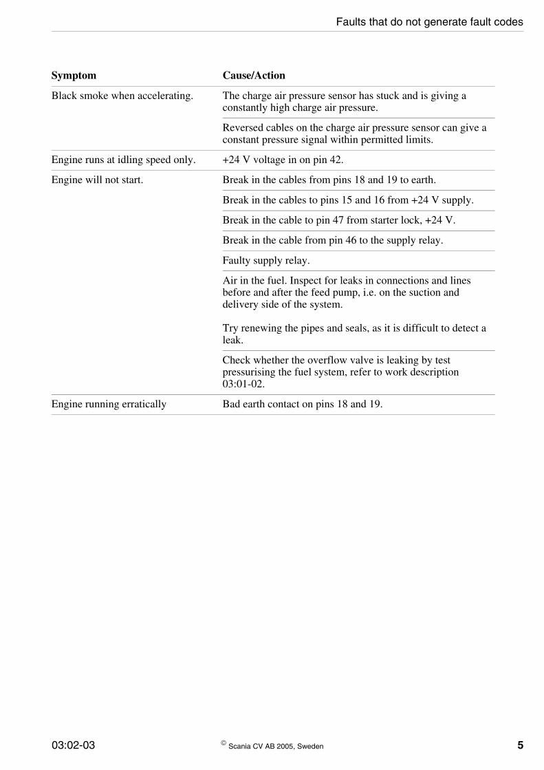
Faults that do not generate fault codes
Symptom Cause/Action
Black smoke when accelerating. The charge air pressure sensor has stuck and is giving a constantly high charge air pressure.
Reversed cables on the charge air pressure sensor can give a constant pressure signal within permitted limits.
Engine runs at idling speed only. +24 V voltage in on pin 42.
Engine will not start. Break in the cables from pins 18 and 19 to earth.
Break in the cables to pins 15 and 16 from +24 V supply.
Break in the cable to pin 47 from starter lock, +24 V.
Break in the cable from pin 46 to the supply relay.
Faulty supply relay.
Air in the fuel. Inspect for leaks in connections and lines before and after the feed pump, i.e. on the suction and delivery side of the system.
Try renewing the pipes and seals, as it is difficult to detect a leak.
Check whether the overflow valve is leaking by test pressurising the fuel system, refer to work description 03:01-02.
Engine running erratically Bad earth contact on pins 18 and 19.
03:02-03 © Scania CV AB 2005, Sweden 5

6
Faults that do not generate fault codes
Symptom Cause/Action
Engine surges slightly when cruise control is disengaged using the brake or clutch pedal.
Brake or clutch pedal switch opens too late.
Cruise control not working. Clutch pedal switch malfunction, which earths pin 26.
+24 V voltage in on pin 40.
Cruise control cannot be disengaged using the clutch pedal.
Clutch pedal switch malfunction, which causes pin 26 not to earth when the pedal is depressed.
The vehicle runs erratically when cruise control is engaged.
Tachograph malfunctioning. The control unit thinks that the road speed is 0 km/h and is attempting to retain a fixed engine speed instead; it is running on the hand throttle function.
Speed limiter not working. Tachograph malfunctioning.
The indicator lamp is on but the diagnostics lamp does not flash any fault codes.
The fault code memory which can be accessed only using Scania Diagnos is full.
Temporary twitches from the engine which can be perceived as misfires.
The control unit miscalculates engine speed and shuts off the fuel supply for a short time. The engine never stops when this occurs, and no fault code is generated on account of the short fuel shutoff time. This fault has been rectified in control units manufactured from May 1997.
© Scania CV AB 2005, Sweden 03:02-03
Fault codes — Working procedure
Fault codes
Working procedure
Try to form a comprehensive view of the problem. Start by asking the driver the following:
• Fault symptoms
• Conditions in which the fault occurs
• How often the fault occurs
• If the warning lamp came on when the fault occurred
• If the warning lamp went out by itself when the fault ceased
• If the driver has erased the fault codes
Then, present all the stored fault codes. Present them either as flashing codes on the EDC diagnostic switch or via Scania Diagnos.
Compare them and try to conclude the probable cause of the fault before taking any other measures. The fault codes are stored in the order they were registered.
03:02-03 © Scania CV AB 2
005, Sweden 7
8
Fault codes — how to read them
How to read fault codes from the diagnostic lamp
© Scania CV AB 2005, S
Two variants of diagnostic switch and diagnostic lamps fitted on trucks.
Diagnostic switch and diagnostic lamp on buses.
EDC
ETC
116
532
EDC
116
533
How to read the fault codes from the diagnostic lamp is described below.
You can see how to interpret the flashing codes on the next page.
1 Switch on the power using the starter key.
2 Press the diagnostic switch and note the number of short and long flashes. You have now presented one of the fault codes.
3 Repeat point 2 until you have presented all the fault codes. If the same fault code is flashed several times, there may only be one fault in the system.
weden 03:02-03

03:02-03 © Scania CV AB 20
Fault codes — how to read them
The long flashes (1 s) that come first represent units of ten. The shorter flashes (0.3 s) that follow represent units of one.
The example on the right symbolises fault code 25.
106
158
A single, very long flash (4 s) means that thereare no fault codes stored in the memory.
05, Sweden 9
10
Fault codes — how to delete them
How to erase fault codes
The EDC control unit memory is able to store 10 fault codes.
The fault codes are stored in two different places in the control unit. Erasing with the diagnostic switch erases the fault codes that are flashed on the diagnostic lamp.
However, the fault codes will remain stored in another memory that can only be accessed using Scania Diagnos.
Scania Diagnos is used to erase both fault code memories at the same time.
How to erase fault codes during delivery inspection
Fault codes are to be erased using Scania Diagnos during delivery inspection so that both memories are empty when the vehicle is delivered to the customer.
© Scania CV AB 2005, Swe
How to erase fault codes that are flashed on the diagnostic switch
How to erase fault codes that are flashed on the diagnostic lamp is described below. These fault codes will still be stored elsewhere in the control unit — these fault codes can be deleted using Scania Diagnos.
1 Start and switch off the engine once so that a shutdown test is carried out. Wait until the EDC warning lamp has gone out.
2 Press the diagnostic switch while turning the starter key to drive position for 3 seconds. Resetting is then complete.
3 Start the engine and check that the warning lamp goes out.
4 Press the diagnostic switch. The fault code memory should be empty; only one long flash should be seen.
den 03:02-03

List of fault codes
List of fault codes
The fault codes are described on the following pages. You will be told why the fault codes have been generated and how the faults can be rectified. The fault codes are described in the same manner in Scania Diagnos.
03:02-03 © Scania CV AB 2
005, Sweden 11
12
List of fault codes
Fault code 11
Fault
At least one of the engine speed signals has shown over 3000 rpm.
Cause
The EDC control unit has detected that the frequency has been too high on at least one of the signals applied to pins 21 and 22.
Remarks
The signal from the main engine speed sensor or auxiliary engine speed sensor has displayed more than 3,000 rpm. The setting solenoid loses power (engine shut down) until both engine speed signals indicate engine speed below 3,000 rpm. Subsequently, the engine will function normally.
This fault code is generated during incorrect downshifting. The fault may also arise if there is interference in the engine speed signal.
Action
Check and compare the signals from the main engine speed sensor and the auxiliary engine speed sensor.
Check any visible faults on the engine speed sensors, connectors and wiring.
Then, erase the fault code memory and check whether the fault code is generated again.
© Scania CV AB 2005, Swe
den 03:02-03
List of fault codes
Fault code 12
Fault
This fault code can be generated for any of four reasons:
1. When the engine is started, the signal from the main engine speed sensor shows a lower engine speed than the signal from the auxiliary engine speed sensor. The main engine speed sensor displays less than 50 rpm while the auxiliary engine speed sensor displays more than 100 rpm.
2. The signal from the main engine speed sensor shows implausible variation in engine speed from pulse to pulse.
3. The signal from the main engine speed sensor indicates a lower engine speed than the signal from the auxiliary engine speed sensor. The auxiliary engine speed sensor indicates above 700 rpm. At the same time, the main engine speed sensor indicates a speed which is below 90% of the speed indicated by the auxiliary engine speed sensor.
4. The signal from the main engine speed sensor shows a persistent recurring fault for each revolution of the engine.
Cause
1. When starting the engine, the frequency of the signal to pin 21 was too low compared with the frequency of the signal to pin 22.
2. The frequency of the signal applied to pin 21 has been too irregular.
3. The frequency of the signal to pin 21 was too low compared with the frequency of the signal to pin 22.
4. The signal to pin 21 had a persistent recurring fault for each revolution of the engine.
Remarks
Engine torque is limited as long as the fault is active. The engine operates as normal if the fault disappears.
03:02-03 © Scania CV AB 2
For safety reasons, the control unit always uses the sensor giving the highest value if the sensors show different speeds. Therefore it is possible that a fault code may sometimes be generated for the sensor that is actually giving the correct value.
The fault code is generated if sensor wiring is incorrectly connected. If the cables are reversed, the signal will be inverted.
The fault can be caused by incorrect clearance between the sensor and the rotating wheel (flywheel or pulse wheel, depending on the engine type).
If fault code 13 is generated at the same time (i.e. both the engine speed sensors are faulty), the engine is switched off (the setting solenoid is not supplied with power).
Action
Check and compare the signals from the main engine speed sensor and the auxiliary engine speed sensor.
Measure the resistance of the main engine speed sensor.
Check any visible faults on the main engine speed sensor, connectors and wiring.
Check for a fault in the timing gear, e.g. excessive play.
Then, erase the fault code memory and check whether the fault code is generated again.
005, Sweden 13

14
List of fault codes
© Scania CV AB 2005, Swe
den 03:02-03
List of fault codes
Fault code 13
Fault
The fault code may be generated for two reasons:
1. The signal from the auxiliary engine speed sensor shows implausible variation in engine speed from pulse to pulse.
2. The signal from the auxiliary engine speed sensor gives a lower engine speed than the signal from the main engine speed sensor. The main engine speed sensor indicates above 700 rpm. At the same time, the auxiliary engine speed sensor indicates a speed which is below 90% of the speed indicated by the main engine speed sensor.
Cause
1. The frequency of the signal applied to pin 22 has been too irregular.
2. The frequency of the signal to pin 22 was too low compared with the frequency of the signal to pin 21.
Remarks
Engine torque is limited as long as the fault is active. The engine operates as normal if the fault disappears.
For safety reasons, the control unit always uses the sensor giving the highest value if the sensors indicate different speeds. Therefore it is possible that a fault code may sometimes be generated for the sensor that is actually giving the correct value.
The fault may be due to incorrect clearance between the sensor and ring gear.
If fault code 12 is generated at the same time (i.e. both the engine speed sensors are faulty), the engine is switched off (the setting solenoid is not supplied with power).
Action
Check and compare the signals from the main
03:02-03 © Scania CV AB 2
engine speed sensor and the auxiliary engine speed sensor.
Measure the resistance of the auxiliary engine speed sensor.
Check any visible faults on the auxiliary engine speed sensor, connectors and wiring.
Check for a fault in the timing gear, e.g. excessive play.
Then, erase the fault code memory and check whether the fault code is generated again.
005, Sweden 15

16
List of fault codes
Fault code 14
Fault
The signal from the coolant temperature sensor has been implausible.
Cause
The voltage between the EDC control unit pins 53 and 13 has been too low or too high.
Remarks
The voltage was lower than 0,44 V (above 130°C) or higher than 4,94 V (below -40°C).
If the voltage is outside the permitted range, the control unit uses a pre-programmed temperature value (40 or 60°C).
If the voltage is outside the permitted range, the control unit uses a pre-programmed temperature value (40 or 60°C, depending on engine type).
As long as the fault is present, the cold starting capacity of the engine is reduced and idle speed cannot be adjusted. If the pre-programmed temperature value is 40°C, the idle speed is raised to 600 rpm. If the pre-programmed temperature value is 60°C, the engine idling speed is not raised; the engine is running at normal idle speed even when cold.
Action
Check the signal from the coolant temperature sensor.
Check that the coolant and charge air are about the same temperature when the engine is cold.
Measure the resistance of the coolant temperature sensor.
Check any visible faults on the coolant temperature sensor, connectors and wiring.
Then, erase the fault code memory and check whether the fault code is generated again.
© Scania CV AB 2005, Swe
den 03:02-03
List of fault codes
Fault code 15
Fault
The signal from the charge air temperature sensor has been implausible.
Cause
The voltage between the EDC control unit pins 55 and 13 has been too low or too high.
Remarks
The voltage was lower than 0,44 V (above 130°C) or higher than 4.94 V (below -40°C).
If the voltage is outside the permitted range, the control unit uses a pre-programmed temperature value (40°C).
As long as the fault is present, the engine responds more slowly than normal to throttle actuation in cold conditions. This is because the smoke limiter is not operating correctly.
Action
Check the signal from the charge air temperature sensor.
Check that the coolant and charge air are about the same temperature when the engine is cold.
Measure the resistance of the charge air temperature sensor.
Check any visible faults on the charge air temperature sensor, connectors and wiring.
Then, erase the fault code memory and check whether the fault code is generated again.
03:02-03 © Scania CV AB 2
005, Sweden 17
18
List of fault codes
Fault code 16
Fault
The signal from the charge air pressure sensor has been implausible.
Cause
The voltage applied to the EDC control unit pin 36 has been too low or too high.
Remarks
The voltage was below 0.33 V (0.5 bar) or above 4.66 V (4.0 bar).
If the voltage is outside the permitted range, the control unit uses a pre-programmed pressure value (approximately 1.7 bar).
The charge air pressure sensor detects the absolute pressure in the intake manifold (the barometric pressure plus the positive pressure provided by the turbocharger).
Engine torque is limited as long as the fault is active.
Action
Check the signal from the charge air pressure sensor.
Check that the charge air and the atmosphere are about the same pressure when the engine is off.
Check any visible faults on the charge air pressure sensor, connectors and wiring.
Then, erase the fault code memory and check whether the fault code is generated again.
© Scania CV AB 2005, Swe
den 03:02-03
List of fault codes
Fault code 21
Fault
The signal from the control for cruise control was implausible.
Cause
Voltage too low or too high between pins 44 and 13. May also be an impermissible voltage level between the different functions: ACC, RES, RET, ON and OFF.
Remarks
The cruise control, hand throttle and engine idling speed adjustment will not function as long as the fault is present.
The control unit interprets voltage level as follows:
0.67-1.03 V, ACC
1.50-1.89 V, RES
2.37-2.82 V, RET
3.20-3.57 V, ON
3.57-4.40 V, OFF
The fault code is generated in the event of voltage levels outside these ranges.
Certain vehicles are not fitted with a control for cruise control. On these vehicles, a resistor is installed between pins 13 and 44 instead of the control for the cruise control. The control unit interprets the voltage level as control for cruise control position ON.
Action
Check the control, connectors and wiring.
03:02-03 © Scania CV AB 2
005, Sweden 19
20
List of fault codes
Fault code 22
Fault
The brake pedal switches have supplied conflicting signals on the position of the pedal. One switch has indicated that the pedal was released while the other switch has indicated that it was depressed.
Cause
Pins 24 and 43 have both been earthed at the same time or they have both been without an earth connection at the same time.
Remarks
Both brake pedal switches have been closed or been open at the same time for more than five minutes.
The cruise control, hand throttle and engine idling speed adjustment will not function as long as the fault is present.
This fault may be due to incorrect adjustment of the switches or because the nut has been over-tightened, causing the switch to stick.
Action
Check the switches, the connectors and wiring.
© Scania CV AB 2005, Swe
den 03:02-03
List of fault codes
Fault code 24
Fault
Signals indicating that the accelerator pedal and the brake pedal have both been depressed at the same time.
Cause
Input voltage on pin 27 too high at the same time as pin 24 has been earthed or pin 43 has not been earthed.
Remarks
The accelerator pedal and brake pedal must have been depressed at the same time for more than 20 consecutive brake applications for the fault code to be generated. The purpose of the fault code is to detect whether the accelerator pedal fails to return as it should, because of a faulty return spring, for example.
The input voltage on pin 27 has been above 0.45 V at the same time as the brake pedal has been depressed.
A fault in the brake pedal switches generates fault code 22. Fault code 25, 41 or 42 is generated if there is a fault in the accelerator pedal sensor's throttle actuation switch or potentiometer.
Action
Check the movement of the accelerator pedal.
03:02-03 © Scania CV AB 2
005, Sweden 21
22
List of fault codes
Fault code 25
Fault
The fault code may be generated for two reasons:
Implausible signal from the accelerator pedal sensor potentiometer.
Implausible deviation between the accelerator pedal sensor potentiometer and the throttle actuation switch.
Cause
Input voltage on pin 27 too low or too high.
Input voltage on pin 27 too low at the same time as pin 39 is earthed. Alternatively, input voltage on pin 27 too high at the same time as pin 39 is not earthed.
Remarks
If the fault is due to an implausible voltage from the potentiometer, the following will apply:
The voltage from the potentiometer was below 0.25 V or in excess of 4.00 V.
The vehicle can be driven to the nearest workshop in limp home mode using the throttle actuation switch. In limp home mode, releasing the accelerator pedal gives engine idling speed and depressing it (throttle actuation switch closed) gives half full throttle.
The cruise control can be used when the road speed exceeds 35 km/h.
Throttle actuation is reduced to engine idling speed when this fault arises. The engine torque is limited.
If the fault is due to an implausible difference between the potentiometer and the throttle actuation switch, the following applies:
The voltage from the potentiometer was lower than 0.49 V while the throttle actuation switch was closed. Alternatively, the voltage was in excess of 0.90 V while the throttle actuation
© Scania CV AB 2005, Swe
switch was open.
The engine runs at a slightly higher than normal idling speed (750 rpm). The engine does not respond to the accelerator pedal. The cruise control can be used when the road speed exceeds 35 km/h.
Action
Check the potentiometer. Compare the potentiometer and throttle actuation switch. Check the connectors and wiring.
den 03:02-03
List of fault codes
Fault code 26
Fault
No road speed signal or it is implausible.
Cause
Input signal to pin 51 is absent, showing implausibly high road speed, has too high a frequency or has too low or too high a voltage level.
Remarks
The signal from the tachograph indicated a road speed in excess of 150 km/h. Cruise control, hand throttle and engine idling speed adjustment do not function.
When this fault is present, the control unit uses a pre-programmed road speed value (15 km/h).
This fault code is also generated in the event of an open circuit or short circuit in the cable between the tachograph and the control unit.
The road speed signal voltage is an internal voltage level in the control unit. It cannot be measured with a multimeter.
Action
Check the function of the tachograph on the disc or during a test drive. If the tachograph is functioning correctly, check the wiring between the tachograph and the control unit.
03:02-03 © Scania CV AB 2
005, Sweden 23
24
List of fault codes
Fault code 27
Fault
No vehicle speed signal or implausibly high speed.
Cause
The signal to pin 51 is not present or the vehicle speed calculated by the control unit is implausibly high.
Remarks
The fault code is generated if there is an open-circuit in the lead between the tachograph and control unit.
Control units manufactured from February 1998 only generate the fault code when the engine is running.
When this fault is present, the control unit uses a pre-programmed road speed value (15 km/h).
The signal from the tachograph indicated a road speed in excess of 150 km/h.
Cruise control, hand throttle and engine idling speed adjustment do not function.
Action
Check the function of the tachograph on the disc or during a test drive. If the tachograph is functioning correctly, check the wiring between the tachograph and the control unit.
© Scania CV AB 2005, Swe
den 03:02-03
List of fault codes
Fault code 28
Fault
Implausible vehicle speed signal.
Cause
The frequency of the signal to pin 51 is too high or the voltage level is too high or too low.
Remarks
Cruise control, hand throttle and engine idling speed adjustment do not function.
When this fault is present, the control unit uses a pre-programmed road speed value (15 km/h).
The fault code may also be generated by external electrical interference.
The fault code is generated if there is a short-circuit to +24 V or chassis earth in the cable between the tachograph and control unit.
Control units manufactured from February 1998 only generate the fault code when the engine is running.
The road speed signal voltage is an internal voltage level in the control unit. It cannot be measured with a multimeter.
Action
Check the function of the tachograph on the disc or during a test drive. If the tachograph is functioning correctly, check the wiring between the tachograph and the control unit.
03:02-03 © Scania CV AB 2
005, Sweden 25
26
List of fault codes
Fault code 31
Fault
The injection timing cannot be correctly set.
Cause
The deviation in time between the signal to pin 32 (needle movement sensor) and the signal to pin 21 (main engine speed sensor) is outside its permitted range.
Remarks
The fault may be due to:
1. Low fuel pressure or incorrectly filled injection pump (air in fuel).
2. Seizing injection pump (prestroke sleeve, prestroke shaft or setting solenoid).
3. Too low opening pressure on the injector with needle movement sensor (during exhaust braking).
4. Incorrect pump basic setting or fault in the pump transmission.
5. The control unit driver stage has stopped functioning.
Engine torque is limited as long as the fault is active.
The fault code can only occur in engines with variable injection timing. The fault may arise in conjunction with fault codes 33, 44 and 45.
Action
Search for air leaks into the fuel system on both the suction and pressure sides.
Check the function of the overflow valve.
Check the fuel valve for loose connection.
Check the injection timing setting solenoid, connectors and wiring.
Check the basic setting of the pump and the mechanical components.
© Scania CV AB 2005, Swe
den 03:02-03
List of fault codes
Fault code 32
Fault
The control rack cannot be correctly set. The reading (actual value) from the control rack position sensor does not correspond with the position the control unit is attempting to set (nominal value).
Cause
The signal from pins 1 and 2 (setting solenoid, fuel volume) does not correspond to the signal to pins 9, 10 and 11 (control rack position sensor).
Remarks
The fault can be caused by the control rack seizing or a defective setting solenoid.
In vehicles manufactured up to and including March 1997, the most common cause of the fault is a short-circuit in the wiring between the engine and the cab. Improved wiring was introduced in March 1997.
The setting solenoid is not supplied with power (the engine is switched off). If the fault disappears by itself, the power supply must be switched off and on (shutdown test) before the control unit can interpret the function as normal.
Control units manufactured from April 1996 are improved and thus not as quick to generate fault code 32.
Action
Check the setting solenoid, the connectors and wiring. Check the control rack movement.
In the event of problems with fault code 32 and sudden engine stoppage in vehicles manufactured up to and including March 1997, it is necessary first to switch to the improved wiring.
03:02-03 © Scania CV AB 2
005, Sweden 27
28
List of fault codes
Fault code 33
Fault
The control unit has interpreted battery voltage as below 9 V.
Cause
Voltage too low to pins 15 and 16.
Remarks
The fault may arise during cold starting if the battery is in poor condition.
Action
Check the battery and alternator. Check the connectors and wiring.
© Scania CV AB 2005, Swe
den 03:02-03
List of fault codes
Fault code 34
Fault
The fault code may be generated for two reasons:
1. Implausible resistance in the circuit for the needle movement sensor.
2. Implausible deviation in the needle movement sensor signal compared with the engine speed.
Cause
1. The control unit has detected that the resistance in the circuit between pins 32 and 17 was too low or too high.
2. The frequency of the signal to pin 32 has deviated from the engine speed to pin 21.
Remarks
Engine torque is limited as long as the fault is active.
The fault code can only occur on engines with variable injection timing. The fault may arise in conjunction with fault code 31.
Air in the fuel system may cause the nozzle needle to open incorrectly, for example, after renewing the fuel filter.
The fault may be due to the nozzle needle seizing.
If the indicator lamp lights during exhaust braking, the opening pressure of the injector with the needle movement sensor has probably been too low.
Action
Check the needle movement sensor, the connectors and wiring.
Search for air leaks in the fuel system. On both the suction side and the pressure side 31.
03:02-03 © Scania CV AB 2
005, Sweden 29
30
List of fault codes
Fault code 35
Fault
Poor contact with the control rack travel sensor signal.
Cause
The control unit has detected that the signal at pins 9, 10 or 11 was too irregular.
Remarks
This fault code is generated if there have been at least 3 occurances of loose connections within 10 seconds. If the fault disappears by itself, the power supply must be switched off and on before the indicator lamp will go out. The fault code should provide a reminder that the vehicle should be taken to the workshop for repair.
The fault may arise in conjunction with fault code 36.
Action
Check the control rack position sensor, connectors and wiring.
Search for open circuits in the wiring. Switch on the power supply. Clear the fault code memory. Shake the connectors and check to see if the fault code is regenerated.
© Scania CV AB 2005, Swe
den 03:02-03
List of fault codes
Fault code 36
Fault
Implausible signal from the control rack position sensor.
Cause
Voltage level too low or too high at pin 9, 10 or 11.
Remarks
On vehicles built up to April 1996 inclusive, the setting solenoid is not supplied with power (the engine is switched off).
On control units manufactured from April 1996 inclusive, the engine speed falls to a speed slightly higher than normal idle speed. The vehicle can be driven to the nearest workshop in limp home mode. The engine does not respond to the accelerator pedal.
The fault may arise in conjunction with fault code 35.
The control rack position sensor voltage is an internal voltage level in the control unit. It cannot be measured with a multimeter.
Action
Check the control rack position sensor, connectors and wiring.
Search for open circuits in the wiring. Switch on the power supply. Clear the fault code memory. Shake the connectors and check to see if the fault code is regenerated.
Check that there is not a short circuit to chassis earth.
03:02-03 © Scania CV AB 2
005, Sweden 31
32
List of fault codes
Fault code 37
Fault
Signal from the emergency shutdown switch.
Cause
Pin 25 on the control unit was earthed.
Remarks
If the vehicle is stationary, the engine is switched off. When the vehicle is being driven, the engine speed drops to idling speed. This allows the use of power steering etc.
The fault code is generated every time the emergency shutdown switch is used. Therefore the system is usually fault free. However, this fault code may be useful if there is a wiring fault between the control unit and the emergency shutdown switch.
This fault code is used only on control units manufactured up to and including April 1996. Newer control units do not generate a fault code when the emergency stop switch is used.
Action
Check the switch, the connectors and wiring.
© Scania CV AB 2005, Swe
den 03:02-03
List of fault codes
Fault code 41
Fault
Implausible signal from the accelerator pedal sensor potentiometer.
Cause
Input voltage on pin 27 too low or too high.
Remarks
The voltage from the potentiometer was below 0.25 V or in excess of 4.00 V.
Throttle actuation is reduced to engine idling speed when this fault arises. The engine torque is limited.
The vehicle can be driven to the nearest workshop in limp home mode using the throttle actuation switch. In limp home mode, if the accelerator pedal is released the engine runs at 750 rpm. If the accelerator pedal is depressed (throttle actuation switch closed) the engine operates at 50% of full throttle. The cruise control can be used when the road speed exceeds 35 km/h.
Action
Check the potentiometer, the connectors and wiring.
03:02-03 © Scania CV AB 2
005, Sweden 33
34
List of fault codes
Fault code 42
Fault
Implausible deviation between the accelerator pedal sensor potentiometer and the throttle actuation switch.
Cause
Input voltage on pin 27 too low at the same time as pin is earthed. The voltage to pin 27 is too high while pin 39 is not earthed.
Remarks
The voltage was below 0.49 V while the throttle actuation switch was closed. Alternatively, the voltage was in excess of 0.90 V while the throttle actuation switch was open.
The vehicle can be driven to the nearest workshop in limp home mode using the throttle actuation switch. In limp home mode, if the accelerator pedal is released the engine operates at the set idle speed. If the throttle pedal is depressed (throttle actuation switch closed) the engine operates at 750 rpm. The cruise control can be used when the road speed exceeds 35 km/h.
Action
Check the potentiometer. Compare the potentiometer and throttle actuation switch. Check the connectors and wiring.
Search for air leaks in the fuel system. On both the suction side and the pressure side.
© Scania CV AB 2005, Swe
den 03:02-03
List of fault codes
Fault code 43
Fault
Fault in the CAN communication circuit.
Cause
Internal fault in the EDC control unit
Remarks
The fault does not affect the function of the engine. However the other control units receive no engine information. Other systems (such as ABS/TC, EBS and Opticruise) cannot take control of engine operation.
If the CAN circuit starts to function properly again, the EDC control unit will first have to carry out a shutdown test before it can regard the fault as inactive.
Action
Erase the fault code memory and check whether the fault code is generated again. Renew the EDC control unit if the fault code is generated again.
03:02-03 © Scania CV AB 2
005, Sweden 35
36
List of fault codes
Fault code 44
Fault
The number of pulses from the needle movement sensor was more than expected compared with engine speed.
Cause
The frequency of the signal to pin 32 has deviated from the engine speed to pin 21.
Remarks
Engine torque is limited as long as the fault is active.
The fault code can only occur in engines with variable injection timing. The fault may arise in conjunction with fault code 31.
If the indicator lamp lights during exhaust braking, the opening pressure of the injector with the needle movement sensor has probably been too low.
Action
Check the needle movement sensor, the connectors and wiring.
Search for air leaks inside the fuel injection system on both the suction and pressure sides.
© Scania CV AB 2005, Swe
den 03:02-03
List of fault codes
Fault code 45
Fault
The number of pulses from the needle movement sensor was less than expected compared with engine speed.
Cause
The frequency of the signal to pin 32 has deviated from the engine speed signal to pin 21.
Remarks
Engine torque is limited as long as the fault is active.
The fault code can only occur on engines with variable injection timing. The fault may arise in conjunction with fault code 31.
Air in the fuel system may cause the nozzle needle to open incorrectly, for example, after renewing the fuel filter.
The fault may be due to the nozzle needle seizing.
Action
Check the needle movement sensor, the connectors and wiring.
Check the injectors.
03:02-03 © Scania CV AB 2
005, Sweden 37
38
List of fault codes
Fault code 46
Fault
Implausible resistance in the circuit for the needle movement sensor.
Cause
The control unit has detected that the resistance in the circuit between pins 32 and 17 was too low or too high.
Remarks
Engine torque is limited as long as the fault is active.
The fault code can only occur on engines with variable injection timing.
Action
Check the needle movement sensor, the connectors and wiring.
© Scania CV AB 2005, Swe
den 03:02-03
List of fault codes
Fault code 61
Fault
The EDC control unit has been interrupted before the shutdown test was finished.
Cause
The input voltage on pins 15 and 16 has disappeared too early.
Remarks
During the shutdown test, the EDC control unit carries out a operational test after the power is switched off using the key.
The engine torque is limited if the shutdown test is interrupted 10 consecutive times. The fault is assumed to have been rectified as soon as the EDC control unit is able to perform a shutdown test without interruption.
The engine must always be switched off using the key. If a battery master switch is fitted, it must not be switched off before the warning lamp goes out.
Action
Check that the warning lamp is on for a short period after the power is switched off using the key.
Check connectors and wiring to the EDC control unit pins 15, 16 and 46. The voltage supply may be interrupted if extra equipment has been connected.
Then, erase the fault code memory and check whether the fault code is generated again.
03:02-03 © Scania CV AB 2
005, Sweden 39
40
List of fault codes
Fault code 62
Fault
Engine speed does not fall quickly enough when the engine is switched off.
Cause
The frequency of the engine speed signals to pins 21 and 22 is not reduced quickly enough when there is no longer any voltage on pin 47.
Remarks
Engine speed must decrease by at least 150 rpm in 4 seconds.
The setting solenoid is not supplied with power (the engine is switched off). Torque is limited the next time the engine is started. Normal torque is resumed if engine speed falls at the correct rate once when the engine is switched off.
The probable cause of fault is air in the fuel system or internal leakage in the fuel valve.
The fault may arise in conjunction with fault code 63.
Action
Check that there is no voltage supply to the fuel valve as soon as the power supply is switched off using the key.
The fuel valve is supplied with voltage again when engine speed has dropped to 350 rpm. The valve is then supplied with voltage until the shutdown test is complete (i.e. the indicator lamp goes out).
Search for air leakage in the fuel system on the line between the fuel valve and feed pump. Check the overflow valve.
© Scania CV AB 2005, Swe
den 03:02-03
List of fault codes
Fault code 63
Fault
Open or short circuit in the circuit controlled by the control unit driver stage.
Cause
Open or short circuit to earth in the lead to pin 14.
Remarks
The fuel valve closes and the engine stops. The engine runs unevenly if there are loose connections.
If the fault disappears by itself, the power supply must be switched off and on (shutdown test) before the control unit can interpret the function as normal.
The fault may arise in conjunction with fault code 62.
Action
Check the connectors, wiring and fuel valve.
03:02-03 © Scania CV AB 2
005, Sweden 41
42
List of fault codes
Fault code 64
Fault
The EDC control unit receives voltage even though the voltage is switched off with the ignition key.
Cause
Input voltage applied to pins 15 and 16 although no input voltage on pin 47.
Remarks
There is still power to the supply relay after the shutdown test is complete.
The warning lamp is on continuously despite the power being switched off. The function of the engine is not affected, i.e. the engine can be restarted.
If the warning lamp is on, the supply relay must be removed before the EDC control unit connector can be disconnected.
Action
Remove the supply relay.
If the warning lamp is still on, the wiring to pins 15 and 16 is probably short-circuited to +24 V.
If the warning lamp goes out, you can measure the resistance in the wire to pin 46 to see if it is short-circuited to earth. If it is not short-circuited, the relay is probably defective. In which case, renew the relay.
Then, erase the fault code memory and check whether the fault code is generated again.
© Scania CV AB 2005, Swe
den 03:02-03
List of fault codes
Fault code 81
Fault
Internal fault in the EDC control unit.
Cause
The two microprocessors of the control unit have lost contact with each other.
Remarks
The setting solenoid is not supplied with power (the engine is switched off).
Action
Renew the EDC control unit.
03:02-03 © Scania CV AB 2
005, Sweden 43
44
List of fault codes
Fault code 82
Fault
The EDC control unit has detected a fault during the shutdown test.
The position of the control rack deviates from the pre-programmed position.
Cause
The signal from pins 1 and 2 (setting solenoid, fuel volume) does not correspond to the signal to pins 9, 10 and 11 (control rack position sensor).
Remarks
During the shutdown test, the control unit sets the control rack to a pre-programmed position. The position sensor is able to read this position. The current to the setting solenoid is then shut off.
Engine torque is limited the next time the engine is started if the control unit detects any faults during this test.
The fault is probably outside the control unit if fault code 82 is generated in conjunction with fault codes 32, 35 or 36.
However, if fault code 82 is generated on its own, this indicates an internal fault in the control unit.
Action
Check whether there are any other fault codes, e.g. 32, 35 and 36. If so, rectify these faults first. The control unit must be renewed if fault code 82 is generated on its own.
© Scania CV AB 2005, Swe
den 03:02-03
List of fault codes
Fault code 83
Fault
Internal fault in the EDC control unit
Cause
The control unit has detected that the fault code memory is not functioning correctly.
Remarks
The fault does not affect engine function.
Action
Erase the fault code memory and check whether the fault code is generated again. Renew the EDC control unit if the fault code is generated again.
03:02-03 © Scania CV AB 2
005, Sweden 45
46
© Scania CV AB 2005, Swe den 03:02-03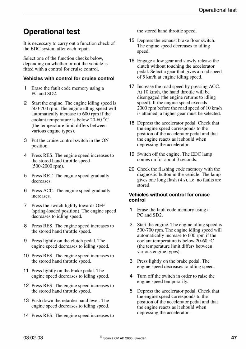
Operational test
Operational testIt is necessary to carry out a function check of the EDC system after each repair.
Select one of the function checks below, depending on whether or not the vehicle is fitted with a control for cruise control.
Vehicles with control for cruise control
1 Erase the fault code memory using a PC and SD2.
2 Start the engine. The engine idling speed is 500-700 rpm. The engine idling speed will automatically increase to 600 rpm if the coolant temperature is below 20-60 °C (the temperature limit differs between various engine types).
3 Put the cruise control switch in the ON position.
4 Press RES. The engine speed increases to the stored hand throttle speed (500-2000 rpm).
5 Press RET. The engine speed gradually decreases.
6 Press ACC. The engine speed gradually increases.
7 Press the switch lightly towards OFF (spring-loaded position). The engine speed decreases to idling speed.
8 Press RES. The engine speed increases to the stored hand throttle speed.
9 Press lightly on the clutch pedal. The engine speed decreases to idling speed.
10 Press RES. The engine speed increases to the stored hand throttle speed.
11 Press lightly on the brake pedal. The engine speed decreases to idling speed.
12 Press RES. The engine speed increases to the stored hand throttle speed.
13 Push down the retarder hand lever. The engine speed decreases to idling speed.
14 Press RES. The engine speed increases to
03:02-03 © Scania CV AB 2
the stored hand throttle speed.
15 Depress the exhaust brake floor switch. The engine speed decreases to idling speed.
16 Engage a low gear and slowly release the clutch without touching the accelerator pedal. Select a gear that gives a road speed of 5 km/h at engine idling speed.
17 Increase the road speed by pressing ACC. At 10 km/h, the hand throttle will be disengaged (the engine returns to idling speed). If the engine speed exceeds 2000 rpm before the road speed of 10 km/h is attained, a higher gear must be selected.
18 Depress the accelerator pedal. Check that the engine speed corresponds to the position of the accelerator pedal and that the engine reacts as it should when depressing the accelerator.
19 Switch off the engine. The EDC lamp comes on for about 3 seconds.
20 Check the flashing code memory with the diagnostic button in the vehicle. The lamp gives one long flash (4 s), i.e. no faults are stored.
Vehicles without control for cruise control
1 Erase the fault code memory using a PC and SD2.
2 Start the engine. The engine idling speed is 500-700 rpm. The engine idling speed will automatically increase to 600 rpm if the coolant temperature is below 20-60 °C (the temperature limit differs between various engine types).
3 Press lightly on the brake pedal. The engine speed decreases to idling speed.
4 Turn off the switch in order to raise the engine speed temporarily.
5 Depress the accelerator pedal. Check that the engine speed corresponds to the position of the accelerator pedal and that the engine reacts as it should when depressing the accelerator.
005, Sweden 47
48
Operational test
6 Switch off the engine. The EDC lamp comes on for about 3 seconds.
7 Check the flashing code memory with the diagnostic button in the vehicle. The lamp gives one long flash (4 s), i.e. no faults are stored.
© Scania CV AB 2005, Swe
den 03:02-03
Component locations and wiring diagrams
Component locations and wiring diagrams
General
On the following pages you will find component locations and wiring diagrams for the following engines:
• 9 litre engine, bus
• 9 litre engine, truck
• 12 litre engine
• 14 litre engine
Further details on how the EDC system is connected to the other vehicle electric systems can be found in the connection and circuit diagrams in Workshop Manual Group 16. Information on the various electrical components in the EDC system can be found in Scania Diagnos and in the section Electrical Components under Group 16. There is also a brief description of checking and renewing the respective component.
03:02-03 © Scania CV AB 2
005, Sweden 49
5
9-litre engine, bus — components
9 litre engine, bus
Fault code links to components and the wiring diagram current paths
Fault code Current path Components affected11 40, 44 Engine speed sensors T74, T75
12 40 Main engine speed sensor T74
13 44 Auxiliary engine speed sensor T75
14 29 Coolant temperature sensor T33
15, 16 32 Charge air sensor T47
21 178, 196 Resistor D532 or control for cruise control S51
22 117 Brake pedal switches B1
24 85, 117 Accelerator pedal sensor D35 and brake pedal switches B1
27, 28 126 Tachograph O4
31 9 Governor E15
32 9 Governor E15
33 68 Supply relay R34
35, 36 9 Governor E15
41 85 Accelerator pedal sensor D35
42 83, 85 Throttle actuation switch B25 and accelerator pedal sensor D35
43 - Control unit E12
44, 45, 46 49 Needle movement sensor T76
61 - Control unit E12
62 5 Fuel valve V45
63 5 Fuel valve V45
64 68 Supply relay R34
81 - Control unit E12
82 9 Governor E15
83 - Control unit E12
0 © Scania CV AB 2005, Sweden 03:02-03
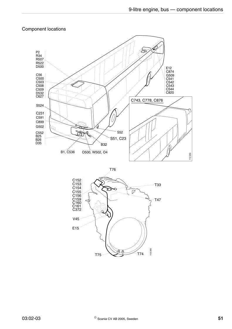
9-litre engine, bus — component locations
Component locations
C743, C778, C876
C231
B32
P2R34R507R522D500
C56C500C503C508C509D532C627
S524
C591C899G502
C552B25B26D35
B1, C536 O500, W502, O4
S52
E12C874G509C541C542C543C544C820
112
204
S51, C23
C152C153C154C155C156C159C160C161C372
V45
E15
T75 T74
T76
T33
T47
112
205
03:02-03 © Scania CV AB 2005, Sweden 51

52
9-litre engine, bus — wiring diagrams
Wiring diagrams
112
162
112
163
© Scania CV AB 2005, Sweden 03:02-03
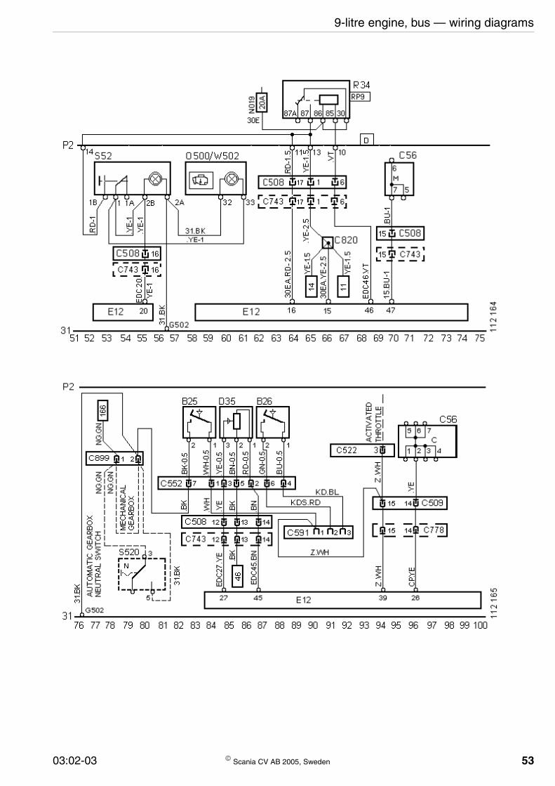
9-litre engine, bus — wiring diagrams
03:02-03 © Scania CV AB 2005, Sweden 53
54
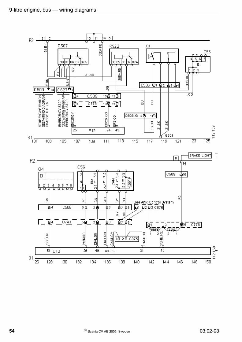
9-litre engine, bus — wiring diagrams
© Scania CV AB 2005, Sweden 03:02-03

9-litre engine, bus — wiring diagrams
03:02-03 © Scania CV AB 2005, Sweden 55

5
9-litre engine, truck — components
9-litre engine in truck
Fault code links to components and the wiring diagram current paths
Fault code Current path Components affected11 8, 59 Engine speed sensors T74, T75
12 8 Main engine speed sensor T74
13 59 Auxiliary engine speed sensor T75
14 12 Coolant temperature sensor T33
15, 16 22 Charge air sensor T47
21 1 Control for cruise control S51
22 115 Brake pedal switches B1
24 71, 115 Accelerator pedal sensor D35 and brake pedal switches B1
27, 28 88 Tachograph O4
31 40 Governor E15
32 40 Governor E15
33 36 Supply relay R34
35, 36 40 Governor E15
41 71 Accelerator pedal sensor D35
42 109, 71 Throttle actuation switch B25 and accelerator pedal sensor D35
43 - Control unit E12
44, 45, 46 63 Needle movement sensor T76
61 - Control unit E12
62 55 Fuel valve V45
63 55 Fuel valve V45
64 36 Supply relay R34
81 - Control unit E12
82 40 Governor E15
83 - Control unit E12
6 © Scania CV AB 2005, Sweden 03:02-03

9-litre engine, truck — component locations
Component locations
B32B25
D35B26
B1B34C56
E12G13
C2C188
C107
D18, P2, R34
W27 S52
G4
O4
S51
G2
118
258
C23C47
C48C61C189C190C191
T74
T75
T76T33
T47C152C153C154C155C156C159C160C161C269
V45
E15
118
524
03:02-03 © Scania CV AB 2005, Sweden 57

58
9-litre engine, truck — wiring diagrams
Wiring diagrams
© Scania CV AB 2005, Sweden 03:02-03
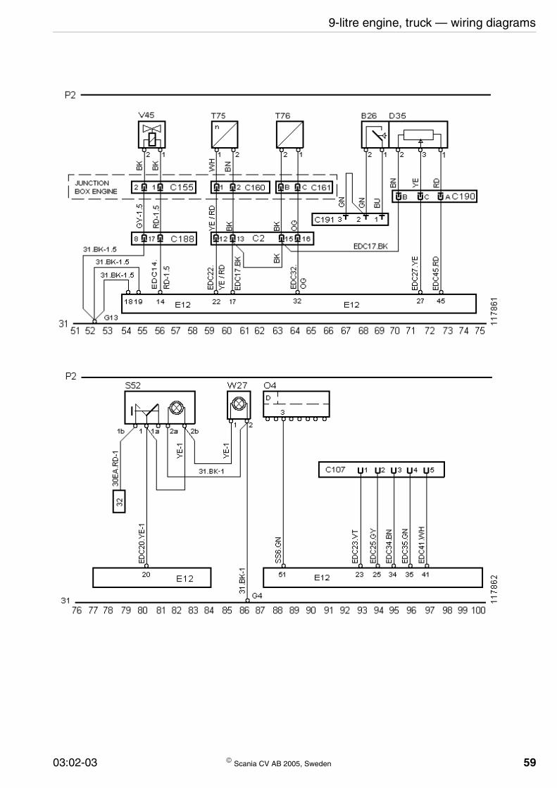
9-litre engine, truck — wiring diagrams
03:02-03 © Scania CV AB 2005, Sweden 59

60
9-litre engine, truck — wiring diagrams
© Scania CV AB 2005, Sweden 03:02-03

03:02-03 © Scania CV AB 2005, Sweden 61
62
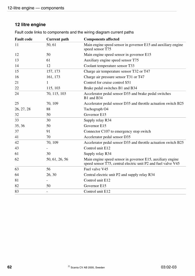
12-litre engine — components
12 litre engine
Fault code links to components and the wiring diagram current paths
Fault code Current path Components affected11 50, 61 Main engine speed sensor in governor E15 and auxiliary engine
speed sensor T75
12 50 Main engine speed sensor in governor E15
13 61 Auxiliary engine speed sensor T75
14 12 Coolant temperature sensor T33
15 157, 173 Charge air temperature sensor T32 or T47
16 161, 173 Charge air pressure sensor T31 or T47
21 1 Control for cruise control S51
22 115, 103 Brake pedal switches B1 and B34
24 70, 115, 103 Accelerator pedal sensor D35 and brake pedal switches B1 and B34
25 70, 109 Accelerator pedal sensor D35 and throttle actuation switch B25
26, 27, 28 88 Tachograph O4
32 50 Governor E15
33 30 Supply relay R34
35, 36 50 Governor E15
37 91 Connector C107 to emergency stop switch
41 70 Accelerator pedal sensor D35
42 70, 109 Accelerator pedal sensor D35 and throttle actuation switch B25
43 - Control unit E12
61 30 Supply relay R34
62 50, 61, 26, 56 Main engine speed sensor in governor E15, auxiliary engine speed sensor T75, central electric unit P2 and fuel valve V45
63 56 Fuel valve V45
64 26, 30 Central electric unit P2 and supply relay R34
81 - Control unit E12
82 50 Governor E15
83 - Control unit E12
© Scania CV AB 2005, Sweden 03:02-03

12-litre engine — component locations
Component locations
118
201
G2C152, C153, C155C156, C157, C158C159, C160
T31T75
B25D35
B31B34
B32T32
T33E15
V45
D18P2R34
E12
C2C188G13
C107
C56
D18P2R34
W27 S52 G4
C23, C47
O4 S51
03:02-03 © Scania CV AB 2005, Sweden 63
64
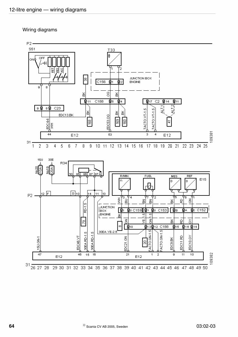
12-litre engine — wiring diagrams
Wiring diagrams
© Scania CV AB 2005, Sweden 03:02-03
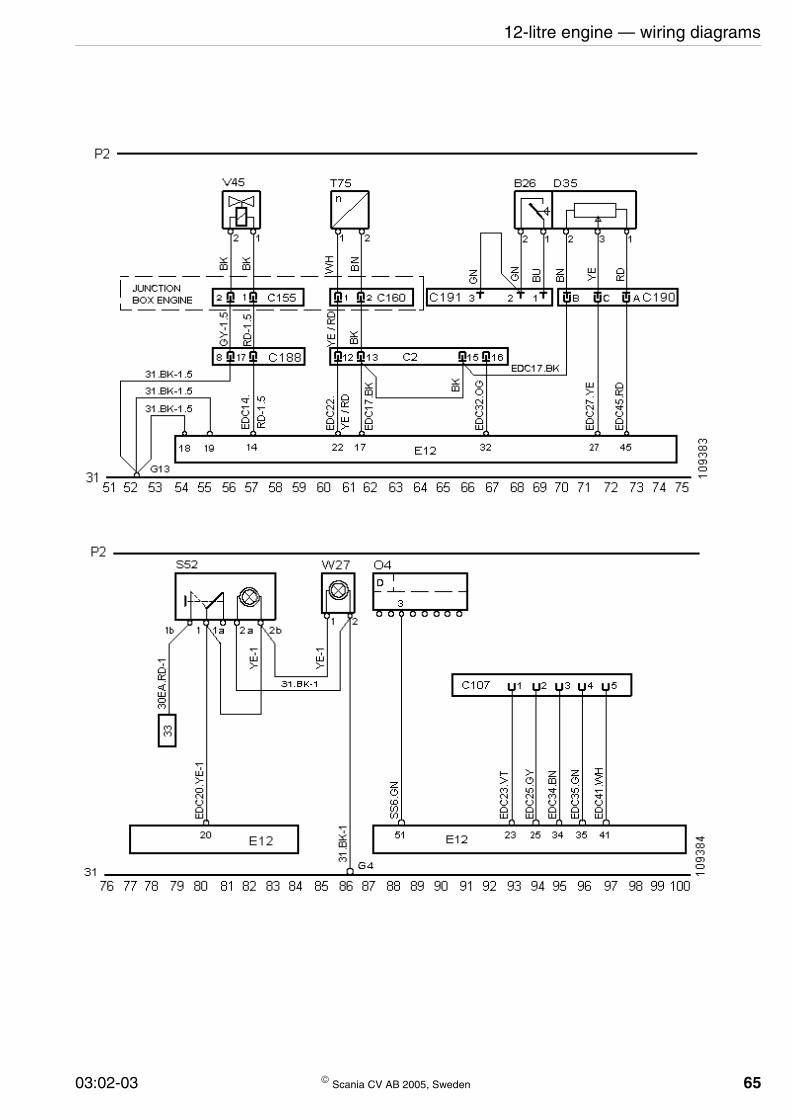
12-litre engine — wiring diagrams
03:02-03 © Scania CV AB 2005, Sweden 65

66
12-litre engine — wiring diagrams
© Scania CV AB 2005, Sweden 03:02-03
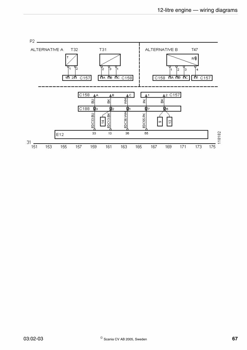
12-litre engine — wiring diagrams
03:02-03 © Scania CV AB 2005, Sweden 67
14-litre engine — components
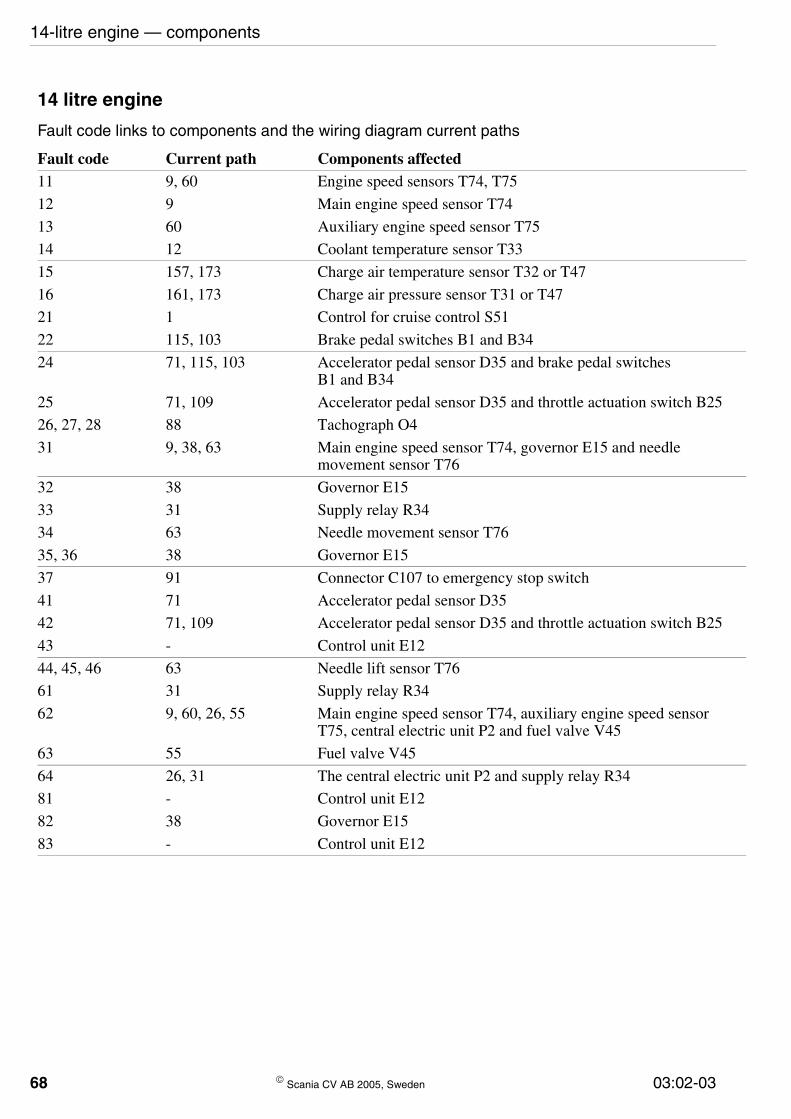
14 litre engine
Fault code links to components and the wiring diagram current paths
Fault code Current path Components affected11 9, 60 Engine speed sensors T74, T75
12 9 Main engine speed sensor T74
13 60 Auxiliary engine speed sensor T75
14 12 Coolant temperature sensor T33
15 157, 173 Charge air temperature sensor T32 or T47
16 161, 173 Charge air pressure sensor T31 or T47
21 1 Control for cruise control S51
22 115, 103 Brake pedal switches B1 and B34
24 71, 115, 103 Accelerator pedal sensor D35 and brake pedal switches B1 and B34
25 71, 109 Accelerator pedal sensor D35 and throttle actuation switch B25
26, 27, 28 88 Tachograph O4
31 9, 38, 63 Main engine speed sensor T74, governor E15 and needle movement sensor T76
32 38 Governor E15
33 31 Supply relay R34
34 63 Needle movement sensor T76
35, 36 38 Governor E15
37 91 Connector C107 to emergency stop switch
41 71 Accelerator pedal sensor D35
42 71, 109 Accelerator pedal sensor D35 and throttle actuation switch B25
43 - Control unit E12
44, 45, 46 63 Needle lift sensor T76
61 31 Supply relay R34
62 9, 60, 26, 55 Main engine speed sensor T74, auxiliary engine speed sensor T75, central electric unit P2 and fuel valve V45
63 55 Fuel valve V45
64 26, 31 The central electric unit P2 and supply relay R34
81 - Control unit E12
82 38 Governor E15
83 - Control unit E12
68 © Scania CV AB 2005, Sweden 03:02-03

14-litre engine — component locations
Component locations
T74 T75 E15 V45
D18, P2, R34
W27 S52 G4
T47 T31T32
118
199
O4
S51
G2
B25D35
E12G13T33T76
B32
B1B34
118
258
03:02-03 © Scania CV AB 2005, Sweden 69
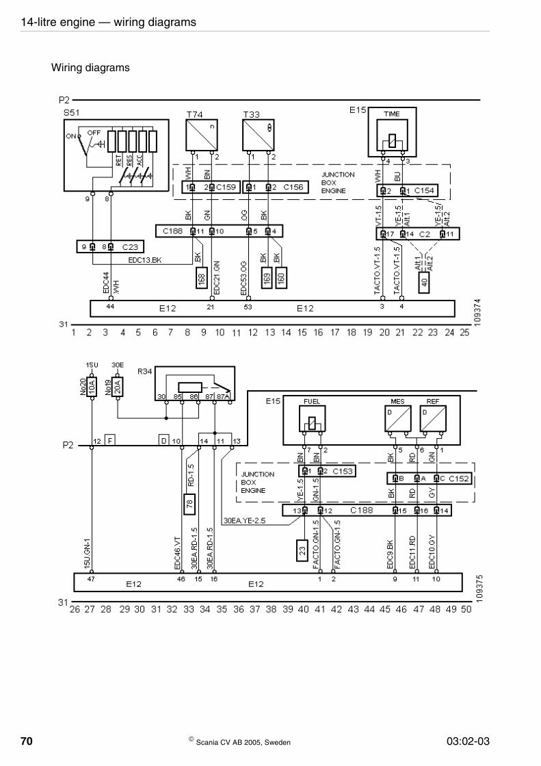
70
14-litre engine — wiring diagrams
Wiring diagrams
© Scania CV AB 2005, Sweden 03:02-03

14-litre engine — wiring diagrams
03:02-03 © Scania CV AB 2005, Sweden 71

72
14-litre engine — wiring diagrams
© Scania CV AB 2005, Sweden 03:02-03

14-litre engine — wiring diagrams
03:02-03 © Scania CV AB 2005, Sweden 73


