WS9TCHW Ver 1.0 Touchscreen Installation - fccid.io · PDF fileThis booklet is available from...
4
Introduction Refer to the iotega Reference Manual for information regarding the limitations of product use and function and manufacturer's liability. Use these instructions with the iotega Reference Manual. The WS9TCHW touchscreen is compatible and intended for use with the iotega Wireless Security System. Mounting the hardware Step 1 Step 2 Step 3 Step 4 Install the wire through the wall for mounting. Attach the mounting plate to the wall with the mounting hardware. If mounting on drywall, mark the four installation points, remove the mounting plate, and install the drywall inserts. Connect the USB cable. Insert the left side of the touch- screen into the mounting bracket at a slight angle. Step 5 Step 6 Step 7 Push the right side of the touch- screen into the mounting bracket. Remove the breakable tab and place the flush wire wall mount through the channel. To remove the touchscreen insert a flat head screwdriver into one of the rear slots at a downward angle and push up to release the touchscreen. Enrolling the touchscreen Step 1 Step 2 Step 3 Step 4 Power up the touchscreen. During power up the following events occur: l The touchscreen keypad flashes. l The Power and Link Speed LEDs illuminate. l The Link Activity LED flashes. l The Remote Connection LED stays on when ready. If it is not enrolled, the serial number and enroll button appears. On the Install App go to Enroll devices. Enter the touchscreen serial number and tap Enroll. WS9TCHW Ver 1.0 Touchscreen Installation
Transcript of WS9TCHW Ver 1.0 Touchscreen Installation - fccid.io · PDF fileThis booklet is available from...

Introduction
Refer to the iotega Reference Manual for information regarding the limitations of product use and function and manufacturer'sliability. Use these instructions with the iotega Reference Manual. The WS9TCHW touchscreen is compatible and intended for usewith the iotega Wireless Security System.
Mounting the hardware
Step 1 Step 2 Step 3 Step 4
Install the wire through the wall formounting.
Attach the mounting plate to the wall with themounting hardware. If mounting on drywall, markthe four installation points, remove the mounting
plate, and install the drywall inserts.
Connect the USB cable. Insert the left side of the touch-screen into the mounting bracket at
a slight angle.
Step 5 Step 6 Step 7
Push the right side of the touch-screen into the mounting bracket.
Remove the breakable tab and place the flushwire wall mount through the channel.
To remove the touchscreen insert a flathead screwdriver into one of the rearslots at a downward angle and push up
to release the touchscreen.
Enrolling the touchscreen
Step 1 Step 2 Step 3 Step 4Power up the touchscreen.
During power up the following eventsoccur:
l The touchscreen keypadflashes.
l The Power and Link SpeedLEDs illuminate.
l The Link Activity LEDflashes.
l The Remote Connection LEDstays on when ready.
If it is not enrolled, the serial number and enrollbutton appears.
On the Install App go to Enroll devices. Enter the touchscreen serial numberand tap Enroll.
WS9TCHW Ver 1.0 Touchscreen Installation

Intended use
Lighting Control Locks Thermostat Garage Door
Each light has an On/Off control iconand a dimmer slider, if supported.
When you enroll multiple lights, youcan turn them on or off
simultaneously.
Each lock has a Lock/unlock controlicon. When you enroll multiple locks,
you can lock or unlock them sim-ultaneously.
View or change the temperature andactivate predefined schedules or
scenes.
Each garage door has an Open/Close control icon.When you enroll multiple garage doors, you can
open or close them simultaneously.
Video Weather Banner Messages
The video menu shows the camerason the system. You can view videos
from a particular camera and use thecamera options to rotate or angle
the image.
Tap the weather icon to bring up aweekly weather forecast menu andthe high and low temperatures for
each day.
When the system receives a highpriority message, a banner appearsand overrides the screensaver. For
low priority messages, an iconappears. Tap the icon to see a list of
available messages.
Environmental requirements
Operating Temperature Humidity Installation Type RoHSThe unit operates normally in a tem-perature range of -10 °C to 55 °C.
The unit operates with a 5% to 93%
RH non-condensing.Indoor, non-hazardous locations. Thismodule is to be installed by service
persons only.
This product is RoHS compliant.
Tablet Specifications
Screen
Type : Capacitive Touch
Size: 7" diagonal
Screen dimensions: 155 x 85 mm(approx)
Resolution (min): 800 x 480 pixels(min)
Dot (Pixel) Shape : Square
Response Time (Tr/Tf): 10/15 ms(Typ.)
Viewing Angle: Right: 60, Left: 60,Up: 60, Down: 60 degrees
Brightness: 400 Nit (Typ.) at 25 C
Backlight Colour: White Colour
Contrast Ratio: 400:1
Colours: 256/65 k
Multi-touch: N/A
Ambient Light Sensor: N/A
Sunlight readable: N/A
Electrical specifications
Primary power source Ratings: Standby Battery Intended applicationPlug in adapter M/N: SEI0502000VHelms-Man Transformers Company limited
Energy Efficiency level 6
4 hour (min) standby, rechargeable 100% up time expected
External power control
OS
N/A (power cycle button)
Android V4.4 or greater
Input: 100 - 240 V~ 50 - 60 Hz 500 mA
Output : 5 V - 2000 mA
Note: USB port only for power supply and battery charging, it cannot connect to PC for communication.
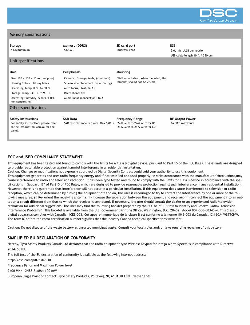
Memory specifications
Storage Memory (DDR3) SD card port USB4 GB minimum 512 MB microSD card 2.0, microUSB connection
USB cable length 10 ft / 350 cm
Unit specifications
Unit Peripherals Mounting
Size: 190 x 110 x 11 mm (approx)
Housing Colour : Glossy black
Operating Temp: 0 °C to 50 °C
Storage Temp: -30 °C to 90 °C
Operating Humidity: 5 to 93% RH,non-condensing
Camera : 3 megapixels; (minimum)
Screen side placement (front facing)
Auto focus, Flash (N/A)
Microphone: Yes
Audio input (connection): N/A
Wall mountable : When mounted, thebracket should not be visible
Other specifications
Safety Instructions SAR Data Frequency Range RF Output PowerFor safety instructions please referto the Installation Manual for thepanel.
SAR test distance is 5 mm. Max SAR is 2412 MHz to 2462 MHz for US 16 dBm maximum
FCC and ISED COMPLIANCE STATEMENTThis equipment has been tested and found to comply with the limits for a Class B digital device, pursuant to Part 15 of the FCC Rules. These limits are designedto provide reasonable protection against harmful interference in a residential installation.Caution: Changes or modifications not expressly approved by Digital Security Controls could void your authority to use this equipment.This equipment generates and uses radio frequency energy and if not installed and used properly, in strict accordance with the manufacturer’sinstructions,maycause interference to radio and television reception. It has been type tested and found to comply with the limits for Class B device in accordance with the spe-cifications in Subpart“ B” of Part15 of FCC Rules, which are designed to provide reasonable protection against such interference in any residential installation.However, there is no guarantee that interference will not occur in a particular installation. If this equipment does cause interference to television or radioreception, which can be determined by turning the equipment off and on, the user is encouraged to try to correct the interference by one or more of the fol-lowing measures: (i) Re- orient the receiving antenna;(ii) increase the separation between the equipment and receiver;(iii) connect the equipment into an out-let on a circuit different from that to which the receiver is connected. If necessary, the user should consult the dealer or an experienced radio/televisiontechnician for additional suggestions. The user may find the following booklet prepared by the FCC helpful:“How to Identify and Resolve Radio/ TelevisionInterference Problems”. This booklet is available from the U.S. Government Printing Office, Washington, D.C. 20402, Stock# 004-000-00345-4. This Class Bdigital apparatus complies with Canadian ICES-003. Cet appareil numérique de la classe B est conforme à la norme NMB-003 du Canada. IC:160A- WS9TCHW.The term IC before the radio certification number signifies that the Industry Canada technical specifications were met.
Caution: Do not dispose of the waste battery as unsorted municipal waste. Consult your local rules and/or laws regarding recycling of this battery.
SIMPLIFIED EU DECLARATION OF CONFORMITYHereby, Tyco Safety Products Canada Ltd declares that the radio equipment type Wireless Keypad for Iotega Alarm System is in compliance with Directive
2014/53/EU.
The full text of the EU declaration of conformity is available at the following Internet address:
http://dsc.com/pdf/1707010
Frequency Bands and Maximum Power level
2400 MHz - 2483.5 MHz: 100 mW
European Single Point of Contact: Tyco Safety Products, Voltaweg 20, 6101 XK Echt, Netherlands
2412 MHz to 2472 MHz for EU

Industry Canada Statement
The device complies with Industry Canada RSS standard(s). Operation is subject to the following two conditions: (1) this device may not cause interference,and (2) this device must accept any interference that may cause undesired operation of the device.
2. Changes or modifications not expressly approved by the party responsible for compliance could void the user's authority to operate the equipment.
Leprésent appareil est conforme aux CNR d'Industrie Canada applicable aux appareils radio.
Exempts de licence. L'exploitation est autorisée aux deux conditions suivantes :
(1) l'appareil ne doit pas produire de brouillage, et (2) l'utilisateur de l'appareil doit accepter tout brouillage radioélectrique subi, meme si le brouillage estsusceptible d'en compromettre le fonctionnement."
Caution
Risk of explosion if battery is replaced
by an incorrect type.
Dispose of used batteries according
to the instructions.
The device is designed and manufactured not to excede the emission
limits for exposure to radio frequency (RF) energy set by the Federal
Communications Commission of the United States.
During SAR testing, the device is set to transmit at its highest certi-
fied power level in all tested frequency bands. Although the SAR is
determined at the highest certified power level, the actual SAR level
of the device while operating can be well below the maximum value.
This is because the device is designed to operate at multiple power
levels so as to use only the power required to reach the network. In
general, the closer you are to a wireless base station antenna, the
lower the power output.
The exposure standard for wireless employs a unit of measurement
known as the Specific Absorption Rate, or SAR. The SAR limit set by
the FCC is 1.6 W/kg.
Tests for SAR are conducted using standard operating positions ac-
cepted by the FCC with the device transmitting at its highest power
level in all tested frequency bands.
The FCC has granted an Equipment Authorization for this model
device with all reported SAR levels evaluated as in compliance with
the FCC RF exposure guidelines. SAR information on this model device
is on file with the FCC and can be found under the Display Grant sec-
tion of www.fcc.goc/oet/ea/fccid, after searching on FCC ID:
F5317WS9TCHW.
For this device, the highest reported SAR value for near the body is
/kg RF exposure in simulated usage near the body with 5 mm
separation.
© 2017 Tyco Security Products. All Rights Reserved. www.dsc.com
29009968R001
0.52W