Ws+ Pum p NEMA - Williams Carverwilliamscarver.com/.../uploads/2014/09/APV-Ws-NEMA-Pump.pdf ·...
39
Instruction Manual Ws+ Pump NEMA Read and understand this manual prior to operating or servicing this product. 341897 ISS Q 06.2008
Transcript of Ws+ Pum p NEMA - Williams Carverwilliamscarver.com/.../uploads/2014/09/APV-Ws-NEMA-Pump.pdf ·...

Instruction Manual
Ws+ Pump NEMA
Read and understand this manual prior to operating or servicing this product.
341897 ISS Q 06.2008
Steve
New Stamp
Steve
New Stamp

Steve
New Stamp
Steve
New Stamp

341897 ISS Q 06.08
Contents: USA
Section Page Description - 1 Introduction- 3 Warnings- 6 Important Cautions
- 8 Sectional Drawing
1 10 Introduction to the Ws+ program1.1 - Ws+ range1.2 - Selection of the standard or simplified pump1.3 - The Ws+ pump, options and extras1.4 - Identifying the pump model
2 11 Installation of the pump2.1 - Reminder2.2 - Installation of pump2.3 12 Installation of pump without recirculation2.4 - Lining up the pipe system2.5 - Power supply2.6 - Water supply for water-flushed shaft seal 3 13 Before start-up3.1 - Checking the pump body for foreign material3.2 - Testing the pump
4 14 Putting the pump into service4.1 - Flushing water
5 14 Maintenance5.1 - Checking the shaft seal5.2 - Replacing the shaft seal5.3 16 Replacement of motor5.4 17 Recommended stocks of spare parts
6 18 Technical data6.1 - Maximum permissible outlet pressure 6.2 - Tightening torque for shaft and air screw
7 20 Pump dimensions
7 22 Spare parts list- - Pump complete- 24 Impeller- 25 Shaft seal- 27 Complete seal kit, single- 28 Complete seal kit, double- 29 O-rings kit- 30 Shaft- 31 Extension frame - Shaft guard- 32 Frame


1
341897 ISS Q 06.08
Congratulations, you are the owner of a quality built item from APV Fluid Handling. This machine was manufactured by the skilled personnel of a company which has served the needs of the dairy, food and process industries for more than 100 years.
The purpose of this manual is to provide instructions for the safe installation, operation and maintenance of your APV Fluid Handling equipment.
Read and understand the entire manual before removing from the crate and installing the equipment.
APV Fluid Handling is committed to provide quality equipment and customer satisfaction. We have a unique network of sales and service support throughout the world, which are listed in this manual. Please note the office located nearest to you. Should you have any questions concerning any information contained in this manual, contact the nearest office or our Lake Mills, Wisconsin office at (920) 648-8311 for assistance.
Standard Warranty
Obligations of Seller During the warranty period, the Seller shall repair, or at Seller's option, replace parts determined by the seller to be defective in material or workmanship. The warranty period is one (1) year from the date of delivery to Buyer F.O.B. point of manufacture. The foregoing shall be the sole obligation of the seller under this warranty with respect to the equipment and the other property included in this agreement. With respect to the equipment, materials, parts and accessories manufactured by others, seller's sole obligation shall be to use reasonable efforts to obtain for the Buyer the full benefit of the manufacturer's warranties
Warranty Exclusions Repair or replacement of parts required because of misuse, improper care or storage, negligence, alterations, accident, use of incompatible supplies or lack of specified maintenance are excluded from the Seller's warranty obligations.
Disclaimer of Warranties The foregoing warranty expressions are in lieu of all other warranties, expressed or implied, including implied warranties of merchantability and fitness for a particular purpose, and existence of any such other warranty is hereby denied.
Limitation of Liability and Remedies The liability of the Seller for breach of any warranty obligation hereunder is limited to:
1. The repair or replacement of the equipment on which the liability is based or,
2. At the Seller's option, the refund to the Buyer of the amount paid by the Buyer to the Seller for said equipment.
Introduction

2
341897 ISS Q 06.08
All other liability of the Seller with respect to this agreement, or from the manufacture, installation, maintenance, repair or use of any equipment covered by or furnished under this agreement, whether in contract or in tort, or otherwise, is limited to the amount paid by the Buyer to the Seller pursuant to the terms herein:
Seller shaft not be liable for incidental or consequential damages of any kind whatsoever. The remedies set forth herein are exclusive.
Breach Any breach by the Seller with respect to any items or unit of equipment shall be deemed a breach with respect to that item or unit only.
Infringement The Seller will not be liable for the infringement of any patent by the Buyer's use of any equipment or materials delivered hereunder.
A word about APV Fluid Handling Service Parts We want to raise your awareness to the problem associated with the purchase of parts not manufactured to the high quality specifications of APV Fluid Handling.
In addition to our high quality, APV Fluid Handling parts are manufactured to meet regulatory agency authorization, approvals and certification (3A Sanitary standards, USDA, ASME, BISSC, and OSHA). Where applicable, materials used in construction of APV parts conform to FDA regulations.
Types of equipment include, but are not limited to, rotary pumps, centrifugal pumps, homogenizers, ice cream freezers, scrape surface heat exchangers, plate heat exchangers, ingredient feeders, process tanks and contact plate freezers.
We bring this potentially serious problem to your attention in order to safeguard your best interest and those of your employees.
If you have any questions, please feel free to call 1-800-358-4100 or your local APV Fluid Handling contact.
Introduction

3
341897 ISS Q 06.08
Parts not manufactured to our specifications may cause damages to your APV Fluid Handling equipment and void all warranties. Use of parts that do not meet APV Fluid Handling specifications may cause property damages and serious bodily injury
Policy regarding availability of service parts APV Fluid Handling will attempt to remain in a position to supply replaceable parts during the normal life of any item of APV Fluid Handling equipment. This contingent upon availability of tools, material, and facilities of our own as well as of our suppliers.
After the expiration of this period, the supply of service parts will be limited to available stock of completed parts. If unable to supply the service part, drawings will be furnished when available to permit local manufacturing, if desired.
APV Fluid Handling reserves the right to improve, change or modify the construction of its equipment or any parts thereof without incurring any obligation to provide like changes to equipment previously sold.
Safety Information
Electrical Hazard A pump is normally powered by an electric motor. This creates a hazard of electrical shock which could cause severe injury or even loss of life.
To minimize the risk of this hazard: All electric/electronic installation, maintenance, and service must be performed by trained and authorized electricians only.
All electric/electronic installation must comply with all applicable codes and standards including those established by OSHA.
Do Not perform any maintenance or service on the motor or any other electrical devices unless the electric power source has been turned off and Locked Out using a locking device for which only the person involved in the maintenance procedure has possession of the key.
Make installation suitable for a wet environment, including: 1. A power disconnect which can be locked in a power Off position and
the key removed. This will allow maintenance or service to be performed without possibility of power being accidentally turned on.
2. Protection of all electric connections within a sealed junction box.
3. Proper grounding of the motor.
4. Protection from flooding. Do not install in an area which could fill with water to a level which contacts the motor.
Warnings

4
341897 ISS Q 06.08
Rotating Parts Hazard Routine cleaning and maintenance procedures require pump disassembly. The pump contains close fitting parts which rotate during operation. Should the pump start unexpectedly while disassembled, severe injury could result.
To minimize the risk of this hazard: 1. Do Not assemble or disassemble the pump
2. Do Not remove the guard from the adapter
3. Do Not perform any maintenance or service on the motor or pump unless the power source has been turned off and locked out, where only the person involved in the maintenance procedure has possession of the key.
High Temperature Hazard Some pump applications may require processing of high temperature fluids and/or the use of high temperature cleaning/ sanitizing solutions. Pumping high temperature fluids creates a hazard of burns to personnel working in the area from contact with the equipment or with leaking fluid
To minimize the risk of this hazard: 1. All installation, maintenance, and service of piping, valves, and other
controls must be performed by trained and authorized plumbers only. This applies to process piping and cleaning/sanitizing piping.
2. All plumbing installation must comply with all applicable codes and standards including those established by OSHA.
3. Do Not perform any maintenance or service on the motor or pump unless the power source has been turned off and locked out, where only the person involved in the maintenance procedure has possession of the key..
4. Never disconnect any lines or fittings (whether process or cleaning/sanitizing) or disassemble the pump until the line is not under pressure and the fluid inside is not hot or harmful.
5. Operating personnel must be authorized and trained.
Warnings

5
341897 ISS Q 06.08
High Pressure Hazard Fluids processed by a pump are under pressure. This creates a hazard to personnel working in the area should a leak occur. Leaking high pressure fluid may cause injury by startling personnel or from actual contact with the leaking fluid.
To minimize the risk of this hazard: 1. All installation, maintenance, and service of piping, valves and other
controls must be performed by trained and authorized plumbers only. This applies to process piping and cleaning/sanitizing piping.
2. All plumbing installation must comply with all applicable codes and standards including those established by OSHA.
3. Never disconnect any lines or fittings (whether process or cleaning/sanitizing) or disassemble the pump when lines are under pressure.
4. Should a leak occur, immediately find the cause and stop the leak.
Never operate the pump when both the inlet valve and the outlet valve are in closed positions. If the pump runs with liquid in it, while the valves controlling the suction and discharge lines are both closed, the liquid in the pump will heat up and turn into vapor, causing a risk of explosion.
To eliminate the risk of explosion, it is strongly recommended that the system into which the pump is installed, include either a pressure relief device which relieves pressure and contains any discharge, or a thermal/pressure overload device to isolate the pump motor in the event of excess temperature/pressure.
Leaking Fluid Hazard Fluid leaks or spills may occur in any pumping system. This creates a hazard to personnel due to slippery floor conditions or contact with possibly hazardous fluids.
To minimize the risk of this hazard: 1. Always clean up leaks and spills immediately.
2. Find and correct the cause of the leak immediately.
Warnings
6
341897 ISS Q 06.08
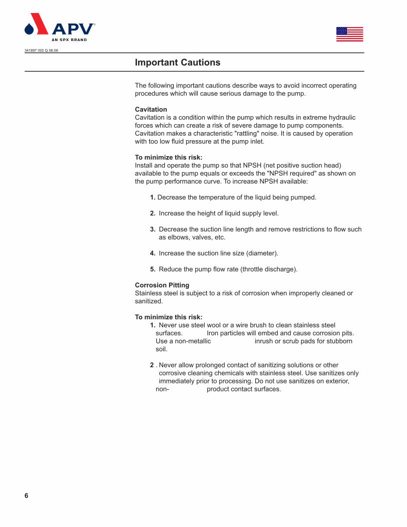
The following important cautions describe ways to avoid incorrect operating procedures which will cause serious damage to the pump.
Cavitation Cavitation is a condition within the pump which results in extreme hydraulic forces which can create a risk of severe damage to pump components. Cavitation makes a characteristic "rattling" noise. It is caused by operation with too low fluid pressure at the pump inlet.
To minimize this risk: Install and operate the pump so that NPSH (net positive suction head) available to the pump equals or exceeds the "NPSH required" as shown on the pump performance curve. To increase NPSH available:
1. Decrease the temperature of the liquid being pumped.
2. Increase the height of liquid supply level.
3. Decrease the suction line length and remove restrictions to flow such as elbows, valves, etc.
4. Increase the suction line size (diameter).
5. Reduce the pump flow rate (throttle discharge).
Corrosion Pitting Stainless steel is subject to a risk of corrosion when improperly cleaned or sanitized.
To minimize this risk: 1. Never use steel wool or a wire brush to clean stainless steel
surfaces. Iron particles will embed and cause corrosion pits. Use a non-metallic inrush or scrub pads for stubborn soil.
2 . Never allow prolonged contact of sanitizing solutions or other corrosive cleaning chemicals with stainless steel. Use sanitizes only immediately prior to processing. Do not use sanitizes on exterior, non- product contact surfaces.
Important Cautions

7
341897 ISS Q 06.08
Motor Overload Depending on the impeller diameter and motor horsepower; there is a risk the pump motor will overload if operated with a fully opened, unrestricted discharge.
To minimize this risk: 1. Before operating the pump, review performance curve and application
giving consideration to motor horsepower and impeller diameter versus expected discharge flow rate and pressure. If the pump is operated with less than expected discharge pressure, the flow rate will increase and the load on the motor will increase.
2. Install a throttling type valve in the discharge piping to allow control of pump discharge flow rate during initial operation. The valve may be removed later when the system is proven to supply adequate discharge pressure to prevent overload.
Impeller Shaft Location The location of the impeller shaft on the motor shaft is critical for correct pump operation and to obtain maxi- mum operating efficiency.
APV Centrifugal Pumps are designed to achieve excellent operating efficiency. This efficiency is possible, in part, because: of precision manufacturing of the pump components. The impeller must be precisely located between the casing and backplate to take full advantage of the pump's operating efficiency.
Incorrect location of the impeller shaft may cause the impeller to contact the casing or the backplate during operation and cause extensive damage to the pump.
The procedures for correctly locating the impeller shaft are described in the Maintenance section. This should be referred to whenever.
1. A new pump is installed onto a motor or pedestal.
2. The impeller shaft is loosened or removed from the motor or pedestal shaft.
3. A replacement casing or backplate is installed.
Important Cautions

341897 ISS Q 06.08
8
NEMASectional Drawing
Section 1
Shaft size ø25 and ø35
Section 2
Shaft size ø25 and ø35
453198 ISS S 03.05

341897 ISS Q 06.08
9
NEMASectional Drawing
1: Pump housing 2: Air screw 3: O-ring 4: Impeller 6: O-ring 7: Back plate 8: Locating pin 9: Clamp ring
11: Shaft 12: Screw 13: Shaft guard 14: Extension frame 15: Bracket (screw) 16: Screw 17: Spacer flange
25: Clamp ring 26: O-ring 27: Front cover 28: Clamp ring 29: Gasket 30: Recirculationpipe
Section 1: Single seal for shaft size ø25 and ø35 Section 2: Double seal with liquid flushing for shaft size ø25 and ø35
5.1: Seal housing 5.3: Pressure ring 5.4: Drain pipe 5.5: O-rings 5.6: Stationary seal face 5.7: Rotary seal face 5.8: Pin 5.9: Seal housing 5.10: O-ring 5.11: Pressure ring
341897 ISS Q 06.08
10
1.1 The Ws+ rangeThis manual covers the standard version of the Ws+ pump, which is supplied pre-fitted with recirculation connection, and a simplified version, which has no recirculation.
Units are designed and constructed to meet the requirements of 3A sanitary standards for cleanability of processing equipment.
1.2 Selection of the standard or simplified pump1. The standard Ws+ pump should be installed as a normal liquid
ring pump, i.e. with a "swan neck" (two x 90° bends) on the inlet and a length of vertical pipe on the outlet. (See length H on the next page)
2. However, in many CIP pump applications it is possible with the Ws+ pump to simplify the pipe layout and bring the inlet pipe direct (horizontally) to the pump inlet and (by selecting the simplified pump) eliminate the recirculation connection. For the pump to function in this manner there is one condition for the inlet pipework which must be met, see Section 2.2. If in doubt, the standard Ws+ with swan neck and recirculation connection must be used.
1.3 The Ws+ pump, options and extras
The following standard options are available in the Ws+range:- with frame and feet- with shaft seal in carbon/SiC or SiC/SiC- with O-rings in EPDM or FPM (Viton)- with single mechanical shaft seal or double mechanical shaft seal
prepared for water-flushed shaft seal. Extras:- drain valve- pump trolley- Ws+pumps can be supplied with all standard welded ferrules (Tri-clamp, bevel seat, ISO etc.).
1.4 Identifying the pump modelA nameplate as is fitted on the extension frame.
Example:Type: Indicates pump model, such as Ws+20/15, Ws+30/30, etc.Serial No.: The “unique” serial number of the pump. Use the serial number whenever requesting information on service parts. Order No.: APV's order number.Year: Indicates the year of manufacture.
1. Introduction to the Ws+ program772476 ISS E
341897 ISS Q 06.08
11
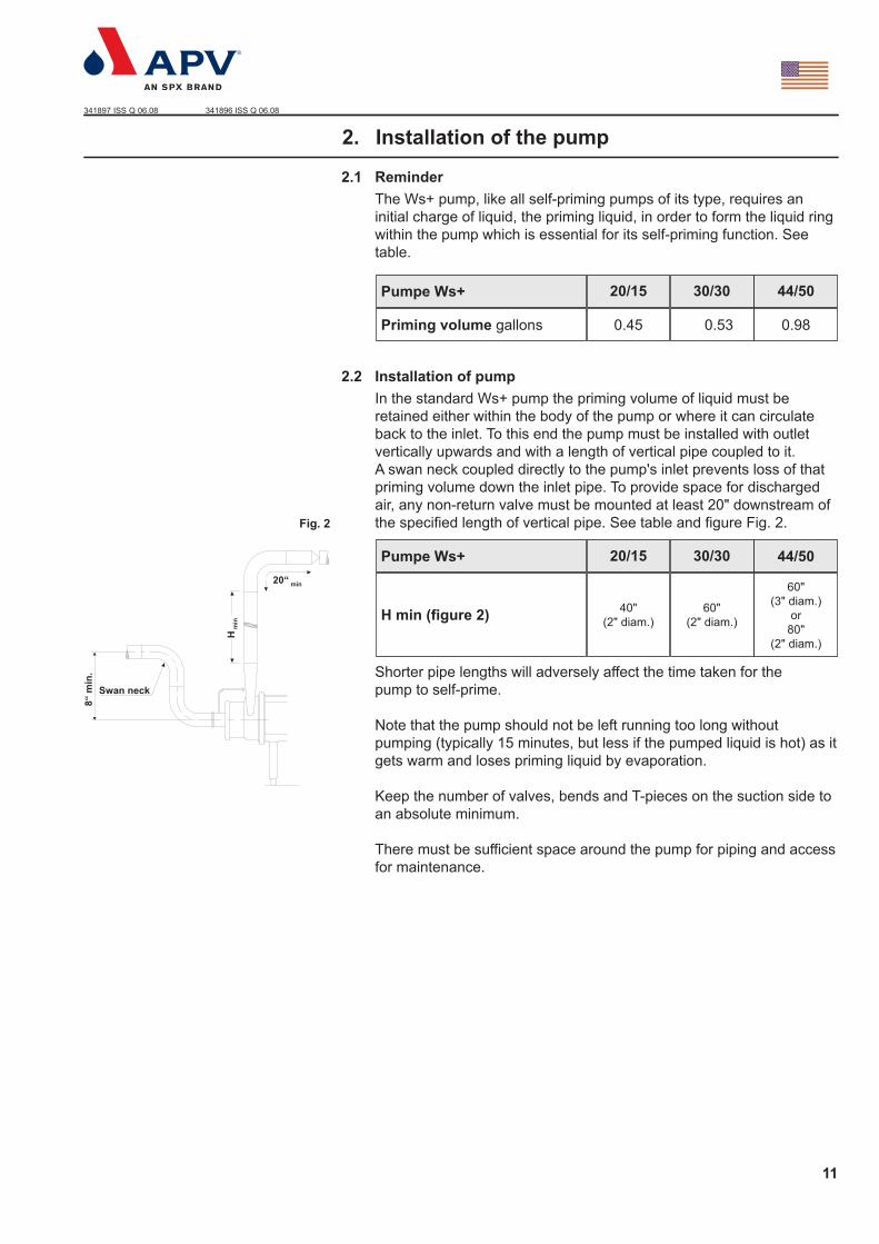
2.1 Reminder The Ws+ pump, like all self-priming pumps of its type, requires an initial charge of liquid, the priming liquid, in order to form the liquid ring within the pump which is essential for its self-priming function. See table.
2.2 Installation of pumpIn the standard Ws+ pump the priming volume of liquid must be retained either within the body of the pump or where it can circulate back to the inlet. To this end the pump must be installed with outlet vertically upwards and with a length of vertical pipe coupled to it. A swan neck coupled directly to the pump's inlet prevents loss of that priming volume down the inlet pipe. To provide space for discharged air, any non-return valve must be mounted at least 20" downstream of the specified length of vertical pipe. See table and figure Fig. 2.
Shorter pipe lengths will adversely affect the time taken for the pump to self-prime.
Note that the pump should not be left running too long without pumping (typically 15 minutes, but less if the pumped liquid is hot) as it gets warm and loses priming liquid by evaporation.
Keep the number of valves, bends and T-pieces on the suction side to an absolute minimum.
There must be sufficient space around the pump for piping and access for maintenance.
2. Installation of the pump
20/15 30/30 44/50Pumpe Ws+
0.45 0.53 0.98Priming volume gallons
20/15 30/30Pumpe Ws+
40" (2" diam.)
60" (2" diam.)
60" (3" diam.)
or 80"
(2" diam.)
H min (figure 2)
44/50
Fig. 2
341896 ISS Q 06.08

341897 ISS Q 06.08
12
2.3 Installation of pump without recirculation. In this case, where the simplified pipe layout is to be used, one important requirement must be met: as the suction tank starts to refill, some liquid will be able to run from the tank into the pump to replenish any priming liquid lost when the tank was previously pumped dry. Typical applications can be seen in figure Fig.3.
As with the ZMS pump, the pump body must always be mounted with outlet vertically upwards and all the other conditions apply.
Note ! Any eccentric reducer should be mounted such that the pump centre line is lower than the inlet pipe's centre line.
2.4 Lining up the pipe systemLine up the pipes carefully to the pump suction and discharge nozzles. Make sure that the pipe system is adequately supported by pipe supports, so that the pump body is not subject to strains and weight from the pipe system.
Note ! During priming the pump may tend to vibrate. A pipe support should be placed close to the pump suction to prevent pipework vibration creating excessive noise.
2.5 Power supplyAll electrical installation must comply with all applicable codes and standards including those established by the Occupational Safety and Health Administration (OSHA).
Install a main power disconnect on-off switch that can be locked in the power off position and have the key removed when service is performed.
Thoroughly read the motor manufacturer’s instructions before making installation.
The motor should be connected such that the rotating direction of the motor (and thus of the impeller) is counterclockwise when viewed from the front towards the suction nozzle of the pump body (Fig. 4).
2.6 Water supply for water-flushed shaft sealPumps with a water-flushed shaft seal have two hose connectors on the seal flange (Fig. 5). The hose connectors are 1/8 inch NPT and fit a 1/4 inch plastic tubing. A flush flow of 4-8 gallons/h is required.Maximum pressure is 100 PSIG.
The hose connection in the seal flange should always be positioned vertically with the fluid inlet underneath and the outlet on top.
Water consumption can be limited by installing a solenoid valve for the flushing water on the supply side. The open/close function of the solenoid valve can be controlled by the pump's start/stop sequence.
2. Installation of the pump
Fig.3
Fig.5
Fig.4
341898 ISS Q 06.08 381326 ISS Q 381325 ISS Q

341897 ISS Q 06.08
13
Before starting the pump, dismantle and clean the suction pipe. Any foreign material in the pump should be removed.
3.1 Checking the pump for foreign materialRemove the front cover, air screw and its housing as described below. The assembly drawing is to be used for reference (page 8).
1. Disconnect the power supply.
2. Remove the front cover by unscrewing the clamp ring (item 25), after disconnecting the re-circulation connection (item 30, if fitted)
3. Unscrew the air screw (item 2) (use a pipe C-spanner or a round bar in the balance hole in the shaft muff to secure the shaft)
4. Remove similarly the housing clamp ring (item 9) and carefully pull off the pump/screw housing
5. Turn the impeller (item 4) to ensure that there is no foreign material behind it.
6. If there is any foreign material in the pump, remove it.
7. When the pump is clean and free of foreign material, reassemble the pump. 8. When mounting the pump/screw housing check that the location pin (item 8, where fitted) in the top of the back plate (item 7), mates with the half hole in the pump body and press the pump/screw housing in over the O-ring (item 6). Re-fit the clamp ring.
9. Screw the air screw on to the shaft. Remember the correct tightening torque - see section 5.2.18.
10. Press the front cover into place and fit the clamp ring. Re-assemble the re-circulation connection (if fitted).
11. Install suction and discharge pipes. Check that the pipe unions have been tightened properly and that pipe supports have been fitted.
To make the front cover and the pump/screw housing easier to fit, we recommend that you give the O-ring a thin layer of food-approved, acid-free grease or soap.
3.2 Testing the pumpTo check that the pump is working properly, pour water into the pump and start it for a moment. Check the direction of rotation (Fig. 4). Listen for any unusual noises.In pumps with water-flushed shaft seals, the seal chamber must be filled with water.
Never allow the pump to run without liquid, as this will ruin the shaft seal.
3. Before start-up
Fig.4
381326 ISS Q

341897 ISS Q 06.08
14
Check the following before starting the pump:- that the shaft guard has been fitted properly- that there is free access for liquid and the pump is primed- that the valve on the discharge side (if fitted) is closedThe valve on the discharge side is closed during start-up to prevent the motor from overloading, but should be opened again as soon as the pump has been started.
Note ! The Ws+ pump should not be left running too long without pumping (typically 15 minutes, if the pumped liquid is not hot), as it gets warm and loses priming liquid by evaporation.
4.1 Flushing water.In pumps with a flushed shaft seal, check that the supply of flushing medium is open and that the flow of the medium is adequate (approx. 4-8 gallons/hour).
5.1 Checking the shaft sealCheck the pump's shaft seal for leaks on a regular basis. If the shaft seal is leaking, replace it as described below.
5.2 Replacing the shaft sealThe sectional drawing shows the pump and position and construction of the shaft seal - both ordinary seals and seals with water flushing.
To replace the shaft seal, it is necessary to dismantle the pump as described below. The sectional drawing is to be used for reference.
1. Disconnect the power supply in the motor isolator by removing the fuses and disconnecting the cables.
2. Turn off the flushing water supply.
3. Close the inlet and discharge of the pump, and drain the pump/screw housing, and make sure that there is no liquid in the pump body.
If the pump is used for hot and/or aggressive liquids, special precautions must be taken. In such cases, observe the local regulations for personal protection when working with these products.
4. Once the inlet and outlet pipes have been properly isolated and the re-circulation connection (if fitted) removed, remove the clamp ring (item 25) and front cover (item 27).
5. Unscrew the air screw (item 2) (use a pipe C-spanner or a round bar in the balance hole in the shaft muff to secure the shaft). Then open the clamp ring (item 9), take off the pump/screw housing (item 1) and remove the impeller (item 4).
Dismantling the pump
4. Putting the pump into service
5. Maintenance

341897 ISS Q 06.08
15
6. Remove the stationary seal face (item 5.6), mounted in the back plate (item 7) with your fingers.
7. Remove the O-ring (item 5.5) from the stationary seal face.
8. Use your fingers to remove the rotary seal face (item 5.7) mounted in the impeller (item 4).
9. Remove the O-ring (item 5.5) from the rotary seal face.
10. Clean the stator and rotary seal face locations, if necessary with air or water.
10a. In the case of water-flushed shaft seals, the back plate must be removed to dismantle the rear shaft seal. The rear stationary seal face (item 5.6) is mounted in the pressure ring (item 5.11) and the rotary seal face (item 5.7) is mounted on the shaft (item 11). These are removed in the same way as the front seal components.
11. Check O-rings (item 5.5) for signs of cracks, lack of elasticity, brittleness and/or chemical attack. Replace worn or defective parts.
12. Check the stationary and rotary seal faces for signs of wear too. The wearing surfaces must be completely free of scratches/cracks. If not, the rings must both be replaced.
12a. In the case of water-flushed shaft seals, check the rear seal rings (item 5.6, 5.7) for wear too, and replace if necessary.
13. Fit new O-rings on the stationary seal face and rotary seal face. NB! Remember to moisten these with water.
14. Fit the rotary seal face (item 5.7) on the impeller without using tools.
NB! The notch in the rotary seal face must be fitted so that it mates with the driving pin (item 5.8) in the impeller hub.
14a. In the case of water-flushed seals, also fit a rotary seal face (item 5.7) with its O-ring (item 5.5) in the location on the shaft - again without using tools.
15. Fit the stationary seal face (item 5.6) in the back plate without using tools.
NB! The notches in the stationary seal face must mate with the driving dogs on the carrier in the back plate. Check that the stationary seal face is positioned so that it slides backwards and forwards easily within the back plate.
15a. When fitting new water-flushed seals, remove the drain pipe (item 5.4) from the stationary seal faces for both the front and rear seal before fitting them in the pressure ring (item 5.11) and back plate respectively.
Checking wearing parts
5. Maintenance
Fitting
Dismantling the shaft seal

341897 ISS Q 06.08
16
16. After fitting, clean the wearing surfaces.
16a. For liquid-flushed, re-mount the back plate.
17. Fit the impeller. Check that the location pin (item 8, where fitted) in the top of the back plate, mates with the half hole in the pump body and carefully, to avoid damaging the O-ring, press the pump/screw housing (item 1) in over the O-ring (item 6). Fasten with the clamp ring (item 9).
18. Re-mount the air screw. Remember to use the proper tightening
torque: M14: 52 lbf ft (70 Nm) M20: 148 lbf ft (200 Nm)
19. Press the front cover into place and fit the clamp ring. Re-assemble the re-circulation connection (if fitted)
5.3 Replacement of motorThe standard motor for the Ws+ pump has a locked front bearing. If the motor is replaced, the new motor must also have a locked front bearing. The motor bearing is enclosed and permanently lubricated.
Follow the instructions below when replacing the motor. For replacement of bearings, see the motor supplier's service instructions.
1. Disconnect the pump from the power supply.
2. Removal of the front cover, air screw, pump/screw housing and impeller (items 27, 2, 1 and 4) is begun as in para. 5.2, points1-5.
3. If possible stand the pump on end. See Fig. 6.
4. Undo the four motor flange bolts and remove them. See Fig. 6.
5. Lift the backplate (item 7) and extension frame (item 14), which are still bolted together, up and off the shaft. See Fig. 6.
Remove the washer (item 17), where fitted.
6. See Fig. 7. Loosen the screws in the shaft muff, pull the shaft off and replace the motor.
7. See Fig. 8. Before re-mounting the pump shaft, remove any dirt and grease from the motor shaft and the muff's internal clamping surfaces. Mount the pump shaft loosely. Position the balance hole over the keyway.
8. Fit the back plate and extension frame over the shaft.
9. Tighten the bolts.
10. Stand the pump back on its legs/bracket.
11. Fit the impeller and secure it temporarily with the nut (M14 or M20) which is supplied as a tool with the pump.
5. Maintenance
Back plate
Screw
Extension frame
Motor
Fig. 6
Fig. 7Shaft Screw
Fig. 8Motor
Keyway
Motor shaft
Balance hole
Pump shaft
N381328 ISS Q N381329 ISS Q N381331 ISS S
341897 ISS Q 06.08
17
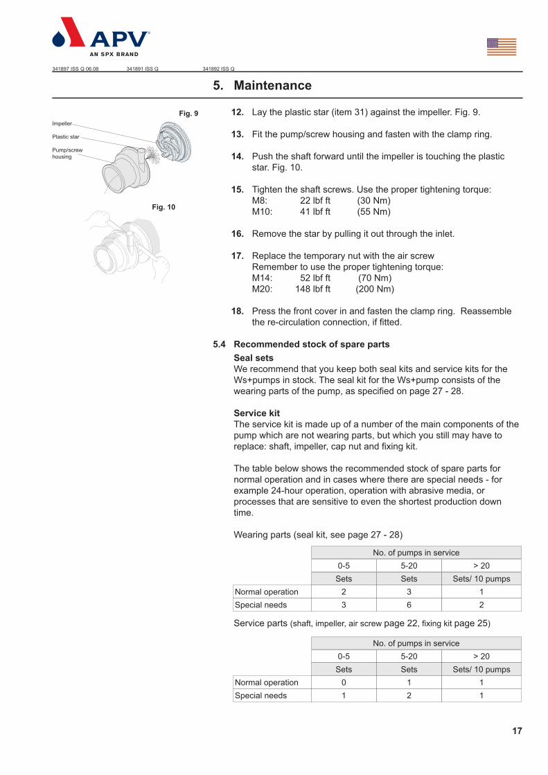
12. Lay the plastic star (item 31) against the impeller. Fig. 9.
13. Fit the pump/screw housing and fasten with the clamp ring.
14. Push the shaft forward until the impeller is touching the plastic star. Fig. 10.
15. Tighten the shaft screws. Use the proper tightening torque: M8: 22 lbf ft (30 Nm) M10: 41 lbf ft (55 Nm)
16. Remove the star by pulling it out through the inlet.
17. Replace the temporary nut with the air screw Remember to use the proper tightening torque: M14: 52 lbf ft (70 Nm) M20: 148 lbf ft (200 Nm)
18. Press the front cover in and fasten the clamp ring. Reassemble the re-circulation connection, if fitted.
5.4 Recommended stock of spare partsSeal setsWe recommend that you keep both seal kits and service kits for the Ws+pumps in stock. The seal kit for the Ws+pump consists of the wearing parts of the pump, as specified on page 27 - 28.
Service kitThe service kit is made up of a number of the main components of the pump which are not wearing parts, but which you still may have to replace: shaft, impeller, cap nut and fixing kit.
The table below shows the recommended stock of spare parts for normal operation and in cases where there are special needs - for example 24-hour operation, operation with abrasive media, or processes that are sensitive to even the shortest production down time.
Wearing parts (seal kit, see page 27 - 28)
Service parts (shaft, impeller, air screw page 22, fixing kit page 25)
5. Maintenance
Normal operationSpecial needs
0-5 5-20 > 20No. of pumps in service
2 3 13 6 2
Sets Sets Sets/ 10 pumps
Normal operationSpecial needs
0-5 5-20 > 20No. of pumps in service
0 1 11 2 1
Sets Sets Sets/ 10 pumps
Impeller
Plastic star
Pump/screwhousing
Fig. 9
Fig. 10
341891 ISS Q 341892 ISS Q

341897 ISS Q 06.08
18
6.1 Maximum permissible outlet pressure for Ws+pumpsThe maximum pump outlet pressures specified below must not be
exceeded (applies to water at 68°F/20°C).
6.2 Tightening torque for shaft and air screwTightening torque required for the screws in the shaft:M8: 22 lbf ft (30 Nm )M10: 41 lbf ft (55 Nm)
Tightening torque required for the air screwM14: 52 lbf ft (70 Nm)M20: 148 lbf ft (200 Nm)
Subject to changes.
Ws+20/15 Ws+30/30 Ws+44/50Pump
189 psig(13 bar)
Maximum permissible pressure
87 psig(6 bar)
116 psig(8 bar)
6. Technical data


Instruction Manual
Ws+ Pump NEMASparepart
Read and understand this manual prior to operating or servicing this product.
341897 ISS Q 06.2008
Steve
New Stamp
NEMA
20
341897 ISS Q 06.08
NEMA7. Pump dimensions
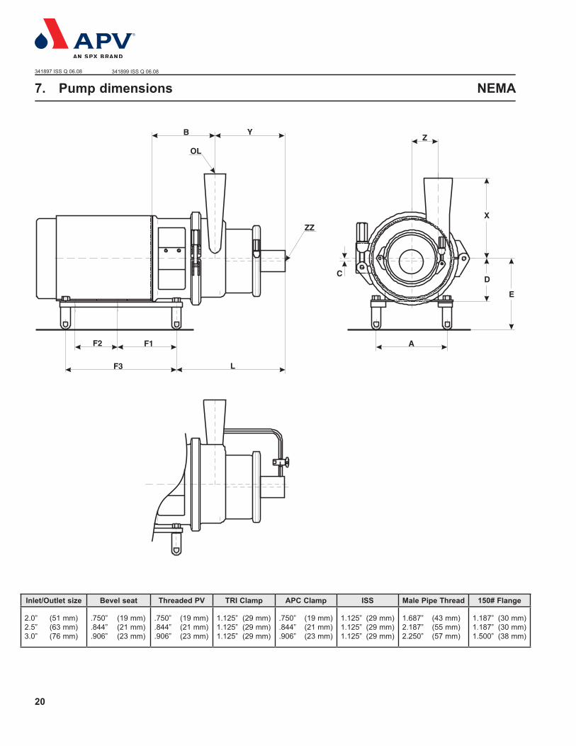
Inlet/Outlet size Bevel seat Threaded PV TRI Clamp APC Clamp ISS Male Pipe Thread 150# Flange
2.0” (51 mm)2.5” (63 mm)3.0” (76 mm)
.750” (19 mm)
.844” (21 mm)
.906” (23 mm)
.750” (19 mm)
.844” (21 mm)
.906” (23 mm)
1.125” (29 mm)1.125” (29 mm)1.125” (29 mm)
.750” (19 mm)
.844” (21 mm)
.906” (23 mm)
1.125” (29 mm)1.125” (29 mm)1.125” (29 mm)
1.687” (43 mm)2.187” (55 mm)2.250” (57 mm)
1.187” (30 mm)1.187” (30 mm)1.500” (38 mm)
341899 ISS Q 06.08
NEMA
21
341897 ISS Q 06.08
NEMA7. Pump dimensions
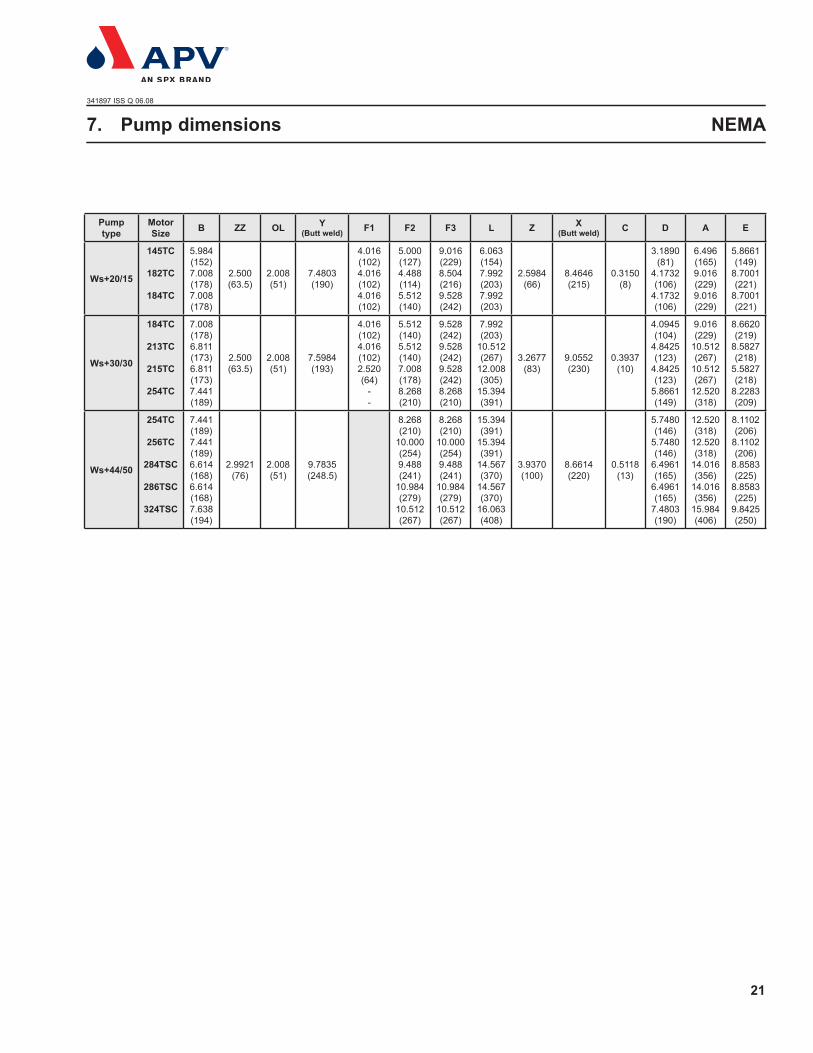
Pump type
Motor Size B ZZ OL Y
(Butt weld) F1 F2 F3 L Z X(Butt weld) C D A E
Ws+20/15
145TC
182TC
184TC
5.984(152)7.008(178)7.008(178)
2.500(63.5)
2.008(51)
7.4803(190)
4.016(102)4.016(102)4.016(102)
5.000(127)4.488(114)5.512(140)
9.016(229)8.504(216)9.528(242)
6.063(154)7.992(203)7.992(203)
2.5984(66)
8.4646(215)
0.3150(8)
3.1890(81)
4.1732(106)
4.1732(106)
6.496(165)9.016(229)9.016(229)
5.8661(149)
8.7001(221)
8.7001(221)
Ws+30/30
184TC
213TC
215TC
254TC
7.008(178)6.811(173)6.811(173)7.441(189)
2.500(63.5)
2.008(51)
7.5984(193)
4.016(102)4.016(102)2.520(64)
--
5.512(140)5.512(140)7.008(178)8.268(210)
9.528(242)9.528(242)9.528(242)8.268(210)
7.992(203)
10.512(267)
12.008(305)
15.394(391)
3.2677(83)
9.0552(230)
0.3937(10)
4.0945(104)
4.8425(123)
4.8425(123)
5.8661(149)
9.016(229)
10.512(267)
10.512(267)
12.520(318)
8.6620(219)
8.5827(218)
5.5827(218)
8.2283(209)
Ws+44/50
254TC
256TC
284TSC
286TSC
324TSC
7.441(189)7.441(189)6.614(168)6.614(168)7.638(194)
2.9921(76)
2.008(51)
9.7835(248.5)
8.268(210)
10.000(254)9.488(241)
10.984(279)
10.512(267)
8.268(210)
10.000(254)9.488(241)
10.984(279)
10.512(267)
15.394(391)
15.394(391)
14.567(370)
14.567(370)
16.063(408)
3.9370(100)
8.6614(220)
0.5118(13)
5.7480(146)
5.7480(146)
6.4961(165)
6.4961(165)
7.4803(190)
12.520(318)
12.520(318)
14.016(356)
14.016(356)
15.984(406)
8.1102(206)
8.1102(206)
8.8583(225)
8.8583(225)
9.8425(250)

NEMA
22
341897 ISS Q 06.08
7. Pump complete 341900 ISS Q 06.08

NEMA
23
341897 ISS Q 06.08
7. Pump complete
** Integrated with extension frame item 14s/pxx = see page
NB! ¤ Part No. mentioned above, do not cover pumps sold with 3.1 certificate. For 3.1 spare parts, contact APV.
Pump typeWs+20/15 Ws+30/30 Ws+44/50
Item Qty. Description Part no.1a 1 Pump housing L804669 L804670 L804671
1b 1 Pump housing L182857 L182858 L182859
2 1 Air screw L804675 L804676 L804677
3 1 O-ring s/p 29 s/p 29 s/p 29
4 1 Impeller s/p 24 s/p 24 s/p 24
5 1 Shaft seal s/p 25 s/p 25 s/p 25
6 1 O-ring s/p 29 s/p 29 s/p 29
7 1 Back plate L260948** L260950 L260954
8 1 Pin -- -- -- L772493 L772493
9 1 Clamp ring L188430 L188436 L188432
11 1 Shaft s/p 30 s/p 30 s/p 30
12 2 Screw s/p 30 s/p 30 s/p 30
13 2 Shaft guard s/p 31 s/p 31 s/p 31
14 1 Extension frame s/p 31 s/p 31 s/p 31
15 2 Bracket (Screw) -- -- -- L268499 L268499
16 2 Screw -- -- -- L701942 L701942
17 1 Spacer flange s/p 31 s/p 31 s/p 31
18 1 Motor -- -- -- -- -- -- -- -- --
25 1 Clamp ring L169050 L188430 L804665
26 1 O-ring s/p 27 s/p 27 s/p 27
27a 1 Front cover L804672 L804673 L804674
27b 1 Front cover L808296 L808297 L808298
28 2 Clamp ring L771837 L771837 L771837
29 2 Gasket s/p 27 s/p 27 s/p 27
30 1 Recirculation pipe L808288 L808289 L808290
31 1 Spacer/Plastic star L259776 L259776 L260406
-- -- -- -- Frame s/p 33 s/p 33 s/p 33
¤¤¤
¤
¤
¤¤
¤

NEMA
24
341897 ISS Q 06.08
7. Impeller
ImpellerDIA
Pump typeWs+20/15 Ws+30/30 Ws+44/50
Part no.8.7" / Ø220 L253777
8.5" / Ø215 L253778
8.3" / Ø210 L253779
8.1" / Ø205 L253780
7.9" / Ø200 L253781
7.7" / Ø195 L253782
7.5" / Ø190 L253783
7.3" / Ø185 L253784
7.1" / Ø180 L253785
6.9" / Ø175 L267000 L253786
6.7" / Ø170 L267001 L253787
6.5" / Ø165 L267002 L253788
6.3" / Ø160 L267003 L253789
6.1" / Ø155 L267004
5.9" / Ø150 L267005
5.7" / Ø145 L267006
5.5" / Ø140 L253767* L267007
5.3" / Ø135 L253768 L267008
5.1" / Ø130 L253769 L267009
4.9" / Ø125 L253770 L267010
4.7" / Ø120 L253771 L267011
4.5" / Ø115 L253772
4.3" / Ø110 L253773
4.1" / Ø105 L253774
3.9" / Ø100 L253775
3.7" / Ø95 L253776
Ws+20/15Ws+30/30
Ws+44/50
* 5.6" / Ø142
381416 ISS T 10.01 381417 ISS T 10.01
NB! Part No. mentioned above, do not cover pumps sold with 3.1 certificate. For 3.1 spare parts, contact APV.

NEMA
25
341897 ISS Q 06.08
7. Shaft seal 381352 ISS U 11.04 381353 ISS T 11.04

NEMA
26
341897 ISS Q 06.08
Single shaft seal complete: 1xFixing kit (enkelt / single) + 1xFace kit + 1xPos. 5.12 Double seal complete *: 1xFixing kit (dobbelt / double) + 2xFace kit + 1xPos. 5.10 + 1xPos. 5.12Wear parts single shaft seal: 1xFace kitWear parts double shaft seal *: 2xFace kitRebuild from single to double seal *: 1xFixing kit (dobbelt / double) + 1xFace kit + 1xPos. 5.10Rebuild from double to single seal: 1xFixing kit (enkelt / single)
* APV recommend the use of SiC/Carbon as secondary seal
** Pump type see page 30 for shaft
Shaft SizeØ25** Ø35**
Item Description Material Part no.Face kit complete:SiC/Carbon seal rings EPDM O-ring L772461 L772466
SiC/Carbon seal rings FPM(Viton) O-ring L772462 L772467
SiC/SiC seal rings EPDM O-ring L772463 L772468
SiC/SiC seal rings FPM(Viton) O-ring L772464 L772469
Containing:5.5 2 off O-rings EPDM or FPM(Viton)
5.6 Stationary seal face Carbon or SiC
5.7 Rotary seal face SIC
5.8 Pin AISI 316
Shaft SizeØ25** Ø35**
Item Description Material Part no.Fixing kit single seal: L772460 L772465
5.1 Seal housing AISI 316
5.2 Spring AISI 316
5.3 Pressure ring AISI 316
5.4 Drain pipe PTFE (L773100) (L773101)
5.12 4 screws (M6x10) AISI 316 L770496 L770496
Fixing kit double seal: L194448 L194449
5.2 Spring AISI 316
5.3 Pressure ring AISI 316
5.9 Seal housing AISI 316
5.11 Pressure ring AISI 316
- Union elbow -
5.10 1 off O-ring EPDM L772470 L771362
5.12 4 screws (M6x10) AISI 316 L770496 L770496
7. Shaft seal

NEMA
27
341897 ISS Q 06.08
7. Complete seal kit, single
Pump TypeWs+20/15 Ws+30/30 Ws+44/50
Item Material Part no.3, 6, 10, 26, 29 x 2,5.4, 5.5 x 2, 5.6, 5.7, 5.8
EPDM - SiC/SiC L808325 L808326 L808327
3, 6, 10, 26, 29 x 2,5.4, 5.5 x 2, 5.6, 5.7, 5.8
EPDM - SiC/Carbon L808328 L808329 L808330
3, 6, 10, 26, 29 x 2,5.4, 5.5 x 2, 5.6, 5.7, 5.8
FPM(Viton) - SiC/SiC L808331 L808332 L808333
3, 6, 10, 26, 29 x 2,5.4, 5.5 x 2, 5.6, 5.7, 5.8
FPM(Viton) - SiC/Carbon L808334 L808335 L808336
453265 ISS T 01.06

NEMA
28
341897 ISS Q 06.08
7. Complete seal kit, double
Pump TypeWs+20/15 Ws+30/30 Ws+44/50
Item Material Part no.3, 6, 10, 26, 29 x 2, 5.5 x 2, 5.6 x 2, 5.7 x 2, 5.8, 5.10
EPDM - SiC/SiC - SiC/Carbon
L808551 L808555 L808559
3, 6, 10, 26, 29 x 2, 5.5 x 2, 5.6 x 2, 5.7 x 2, 5.8, 5.10
EPDM - SiC/Carbon -SiC/Carbon
L808552 L808556 L808534
3, 6, 10, 26, 29 x 2, 5.5 x 2, 5.6 x 2, 5.7 x 2, 5.8, 5.10
FPM(Viton) - SiC/SiC -SiC/Carbon
L808553 L808557 L808535
3, 6, 10, 26, 29 x 2, 5.5 x 2, 5.6 x 2, 5.7 x 2, 5.8, 5.10
FPM(Viton) - SiC/Carbon -SiC/Carbon
L808554 L808558 L808536
453265_1 ISS A

NEMA
29
341897 ISS Q 06.08
7. O-rings kit
Pump TypeWs+20/15 Ws+30/30 Ws+44/50
Item Material Part no.3, 6, 10, 26 & 29 x 2 EPDM L808619 L808620 L808621
3, 6, 10, 26 & 29 x 2 FPM(Viton) L808622 L808623 L808624
381654 ISS S

NEMA
30
341897 ISS Q 06.08
Pump typeMotor
145TC 182-184TC 213-215TC 254TC 254-256TC 284-286TSC 324TSCShaft Ø25 Item 11 Shaft Ø35 Item 11
Ws+20/15 L267333 L267334
Ws+30/30 L267333 L267334 L267335 L267336
Ws+44/50 L267341 L267342 L267343
Item 12Qty. 2 2 2 2 2 2 2
Screw L771199 L771199 L771199 L771199 L771199 L771199 L701700
7. Shaft453351 ISS S 06.06

NEMA
31
341897 ISS Q 06.08
7. Extension frame - Shaft guard
Item 14 Extension Frame
******
L267344L267345L267346
Item 17 Flange Adapter
Pump TypeMotor
145TC 182TC 184TC 213TC 215TC 254TC** 256TC** 284TSC 286TSC 324TSC***Part no. Item 13
Ws+20/15 L260973# L260973#* L260973#*Ws+30/30 L260975 L260975 L260975 L260975
Ws+44/50 L260977 L260977 L260978 L260978 L260978
453352 ISS S 06.06
Pump Type Qty.Motor
145TC 182TC 184TC 213TC 215TC 254TC 256TC 284TSC 286TSC 324TSCPart no. Item 13
Ws+20/15 2 R/L L188334 L188334 L188334
Ws+30/30 2 R/L L188653 L188653 L188653 L188653
Ws+44/50 2 R/L L188653 L188653 L188811 L188811 L188811
R = RightL = Left
Item 13 Shaft Guard
# Integrated with back blate item 7

NEMA
32
341897 ISS Q 06.08
7. Frame341901 ISS Q 06.08

NEMA
33
341897 ISS Q 06.08
7. Frame
A B
Item Description Qty. Part no. Qty. Part no.1 Plate 2 L273992 - -- -- --
2 Ball type foot 4 L800868 4 L268468
3 Leg - -- -- -- - -- -- --
4 Screw 6 L700234 4 L772459
4.1 Screw - -- -- -- - -- -- --
5 Washer 6 L771174 4 L772450
6 nut 2 L700241 - -- -- --
Pump typeMotor Ws+20/15 Ws+30/30 Ws+44/50145TC A
182TC A
184TC A A
213TC A
215TC A
254TC B B
256TC B
284TSC B
286TSC B
324TSC B

Your local contact:
APV A/S Platinvej 8 6000 Kolding Phone: +45 70 278 444 Fax: +45 70 278 445
For more information about our worldwide locations, approvals, certifications, and local representatives, please visit www.apv.com.
Copyright © 2008 SPX Corporation
The information contained in this document, including any specifications and other product details, are subject to change without notice. While we have taken care to ensure the information is accurate at the time of going to press, we assume no responsibility for errors or omissions nor for any damages resulting from the use of the information contained herein.
Steve
New Stamp
Steve
New Stamp